data transfer concepts for electronic charting - amos...
TRANSCRIPT

Data Transfer Concepts for Electronic ChartingR. Alfredo C. Siochi, PhD
University of Iowa Hospitals and Clinics

Outline1. IT Infrastructure
a) Networks – physical structureb) Transport Protocolsc) DICOM, HL7
2. Data Repositoriesa) File Systemsb) Databases
3. Models of Data Flowa) Distributedb) Centralizedc) Examples

Outline-II4. Data Transfer Matrix
a) Subsystems in Rad Oncb) Example Matrixc) Testing
5. Quality Assurance and Control Basicsa) Principal concepts: Physical Integrity and Logical
Consistencyb) ATP and Commissioningc) Annuald) Patient QC

Networks• Link computers together
– Including computers that drive treatments!
– Can be across continents• Various architectures possible• Rad Onc should be behind a firewall• Connections: cables, optical fiber,
routers, “wireless”…

Network Diagrams
Is Your Rad Onc Network Here ?

Mailman analogy
• Houses = computers• House Address = ip Address• Residents = ports• Post office = finds appropriate routes• Roads = cables / wireless• The analogy breaks down with the lower
layers…

OSI 7 layers• Physical through Logical• package up the information for
sending• Analyze the package for receiving• Transport information
– Computer: ip address– Software Application: port
• DICOM layer: AE title

Open Systems Interconnect
Translate, Encrypt, Compress
Establish, Maintain, Synchronize interactions
Decompress, Decrypt, Translate
Entire message reassembled, origin to destination
Packets from origin to destination, logical-physical address mapping
Node to node transmission of data frames
Split message into smaller parts

TCP/IP - OSI
Ethernet, etc
IP
TCP
SMTP (mail), HTTP (web), FTP, Telnet
Entire data stream
Packets framed with header (addresses, error checking)
Determine routing and add IP header
IP frame transmission

DICOM, HL7
• Primary protocols in a hospital setting• TCP/IP • DICOM-RT: RT treatment data• HL7: Admissions, Discharge,
Transfer, labs, billing….

Information vs Data• Data are associated with attributes• There should be enough attributes to be
unambiguous
99
Value attribute
?information
age A very old person
Code number Maxwell Smart’s sidekick?
?
Weight May be light or heavy. Lbs or Kg?

Attributes determined from:
• DICOM: Information Object Definition (IOD)
• HL7 – message headers and expected record position within the message

DICOM Applications
• Picture Archiving and Communications System (PACS)
• DICOM-RT capable treatment planning systems, for export to R&V and IGRT systems
• DICOM from imaging systems to treatment planning systems

Making the Connection
A DICOM network uses the underlying TCP/IP infrastructure.
http://worldrec.info/2006/10/26/the-worlds-messiest-network-cable-arrangements
I hope your DICOM “physical layer” looks better than this!

Application Entities (AEs)• Software application residing on a
computer with a static IP address• Default port 104 • or any unused port as long as receivers
and senders use the same one• Other configurations possible but more
complex

The quad core AE knows about the Coherence workstation ONC05PHYSICS

Coherence knows about the quad core AE and its supported Dicom Services

ASSOCIATIONS
• A handshake, a dialogue to make a contract
• Check that AEs are compatible– Able to perform requested service
• Ensure AEs agree on data transfer– Have at least one common transfer syntax

Services• An AE can be a
– Service Class Provider (SCP)– Service Class User (SCU)
• SCP responds to request of SCU to provide a service:– Service Object Pair (SOP = command + IOD)
• CT image Storage = C-Store (push) + CT image• Commands (DICOM Message Service Elements,
DIMSE): C-Find, C-Echo (ping), C-Move or C-Get (pull)

What gets transferred?
From “Informatics in Radiation Oncology”, eds. Siochi and Starkschall, – Ch. 11, Information Resources for Radiation Oncology by R.A.C. Siochi- In Press.
Optional for Implicit VR transfer syntax
Information about data elements are found in the data dictionary by using the tag
Data set broken into PData TF PDUs for communication only
Data set logically comprised of data elements
Protocol data unit = PDU

What happens after the transfer ? Depends on your AE:
• Bytes stored in proprietary format in a proprietary database known only to the AE
• Bytes stored in DICOM part 10 format as a dicomfile in a proprietary database.– Essentially a “transcript” of the dicom transfer– Includes a metafile to handle transfer syntax
• Part 10 format file stored in a folder• DICOM file service is used to store part 10 format
files (becomes abstract to media storage)• *.dcm, *.ima – let’s take a closer look…

Excerpt from a Data Dictionary
Tag:Hexadecimal,2 bytes each for group and element-unique identifier for the attribute
Value Multiplicity –The number of items in this data element, separated by “\” for character strings
Value Representation(unsigned short)
A stream of words or bytes
From “Informatics in Radiation Oncology”, eds. Starkschall and Siochi, – Ch. 11, Information Resources for Radiation Oncology by R.A.C. Siochi- In Press.

Using the Data Dictionary• IF your application can’t read a Dicom file, it
might have encountered a data element whose tag is not listed in the application’s dictionary
• Implicit VR: VR must be determined from a Dictionary
• Converting the data into human readable form requires getting the Item name from the Dictionary (to serve as a label)

DICOM-RT• Uses the same paradigm for data
elements, file structure and communication
• Several Modules– RT Series– RT Image (conical imaging geometry)– RT Dose– RT DVH– Structure Set– ROI Contour– RT Dose ROI– RT General Plan*– RT Prescription*– RT Tolerance Tables*– RT Patient Setup*– RT Fraction Scheme*– RT Beams*– RT Brachy Application Setups– Approval– RT General Treatment Record– RT Treatment Machine Record– Measured Dose Reference Record– Calculated Dose Reference Record– RT Beams Session Record– RT Brachy Session Record– RT Treatment Summary record
RT-Plan Modules for external beam treatments
RT-Record Modules

DICOM-RT Modules
• Designed to completely describe– Treatment Plan– Delivered Treatments
• References associated Images• Some images may be the planning images (CT,
MR) that were used for contouring• Others may be RT Images (DRRs, portal
images, CBCT).

RT-Plan• Probably most important DICOM RT IOD to
know• Used by some systems for export/import to/from
Record & Verify• Not easy to read even when put in “human-
readable” form– Too many references– Doesn’t easily fit our pre-conceived treatment beam
model– IEC 61217 coordinate conventions
• Need applications to convert it into something that we are used to seeing (e.g. MUs belong with the field, native coordinates)

Clinical Issues in RT
• DICOM is used to transfer plan information from the TPS to the R&V and IGRT systems
• If there is a problem with the transfer, how do you troubleshoot it?
• If you need to extract other information, what do you do?
• Need DICOM aware applications• DICOM readers, viewers, editors• DICOM servers

DICOM software• Do a Google search• DICOM +
– Viewer– Reader– Server– Anonymizer– Editor
• They may not do all that you want nor how you want it done
• Shop around, test drive them• Also, see what your TPS or RT-PACS can do

Example: Connectivity• Archive A was retired and Data was
transferred to Archive B.• Archive B would not accept a particular
study with CT Images from Archive A• Archive A sent the study to
CONQUESTSRV1• CONQUESTSRV1 sent the study to other
stations where it was needed (could not be pushed to or pulled by Archive B, however.)

HL7
• Primarily for Hospital Information Systems• Main issue for Rad Onc: demographics,
scheduling, billing.• Synchronize hospital data with Rad Onc
Information System / EMR/TMS (e.g. Mosaiq, Aria)

Example HL7 message
MSH|^~\&|CLOVERLEAF|UIHC|LANTIS|UIHC|201301081413||BAR^P01|62830_33_RE|P|2.3||||||ASCIIEVN|P01|201301081413|||JEG475PID|1||05979249^^^IDX||DOE^JANE||19800302|F|||123 45TH ST^^MARION^IA^52302-1234^USPV1|001
4 Segments in this message:MSH = Message HeaderEVN = Event typePID = Patient DemographicsPV1 = Patient Visit Information
PID segment made of several fields| separates fieldsSequence of fields determines the meaninge.g. 5th field is the patient’s name

HL7 transmission
• TCP/IP• Minimal Lower Layer Protocol• Add a message header and footer to delimit
messages• Use ACK(nowledgment) and NAK messages• HL7 TCP/IP listener/router application• Sender sends to Listener’s IP/port

HL7 Issues• Messaging System• Needs a log of transactions• Needs a mechanism to verify uptime• Mechanism is on sender and listener end• Example Error: System down, lab results
not sent, physician assumed labs OK, and a patient died as a result.

HL7 and Rad Onc
• Primarily demographics• Name and Birthday are critical identifiers• How do you know if you have the right
patient?• Verify patient registration in RO EMR with
patient

Data Repositories• Once Data has been generated or
transported, where do they go?• Folders / Files – directories on the hard drive
– Example: Pinnacle plan.trial file holds all the treatment plan information
• Databases– Example: EPIC, MOSAIQ, ARIA

File System

Databases

38
Database basics
• DB consists of Tables• Table: consists of rows (aka records)• Row: contains column elements (aka fields)• Queries
– E.g. how many patients had IMRT this month?– SQL (Structured Query Language)

DB Tables
T_ID First Last MI SSN MRN License
45 Alpha Omega 123456789 123 abc
72 Primero Ultimo M 987654321 456 def
73 Alias Omega 123456789 123 abc
Primary Key must be unique
Record (row)Field (column)
Field or Column Names define the table
40
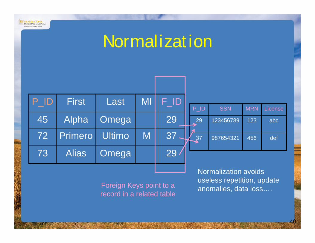
Normalization
P_ID First Last MI F_ID
45 Alpha Omega 29
72 Primero Ultimo M 37
73 Alias Omega 29
Foreign Keys point to a record in a related table
P_ID SSN MRN License
29 123456789 123 abc
37 987654321 456 def
Normalization avoids useless repetition, update anomalies, data loss….

41
Typical Tables in an RT DBIn order to “incorporate” tables into other tables, foreign keys are used to point back to the related tables.
Here, each record in the Tx_Fieldstable consists of parameters that describe Linac settings. One of the parameters, control points, is a set of records in another table, with a “foreign key” that points back to the Tx_Field record to which it belongs.
DATA DICTIONARY – provides the definitions of the tables and the relationships among them.

42
Data Flow in RO
*Fig. 11.1 from Siochi, Information resources for radiation oncology,Ch. 11 of a forthcoming book:Informatics in Radiation Oncology, G. Starkschall, R. Siochi, editors.

43
Distributed system data flow
Redundant data living in many places: INFORMATION should match.(Data might be stored in different forms but mean the same thing.)
44
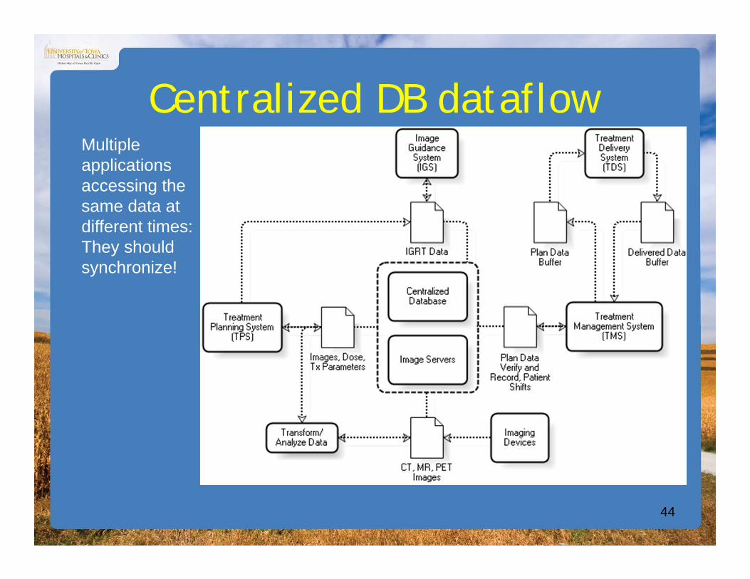
Centralized DB dataflowMultiple applications accessing the same data at different times: They should synchronize!

Examples
• Distributed– Pinnacle transfers RT plan to MOSAIQ– MOSAIQ transfers RT plan to Linac Console
• “Centralized”– Eclipse RT plan is created, using Aria to hold
the RT plan database elements– …hybrid… still have to transfer to 4D ITC.

Why should it matter what I have?
• Affects testing because of data state• Centralized DB has to deal with
concurrency issues and caching.• Distributed DB has to deal with data
transfer errors and updates to all systems for changed data

Data Transfer Matrix
• Table with 1st column containing source• 1st row containing destination• The cell at an intersection is the data to be
transferred
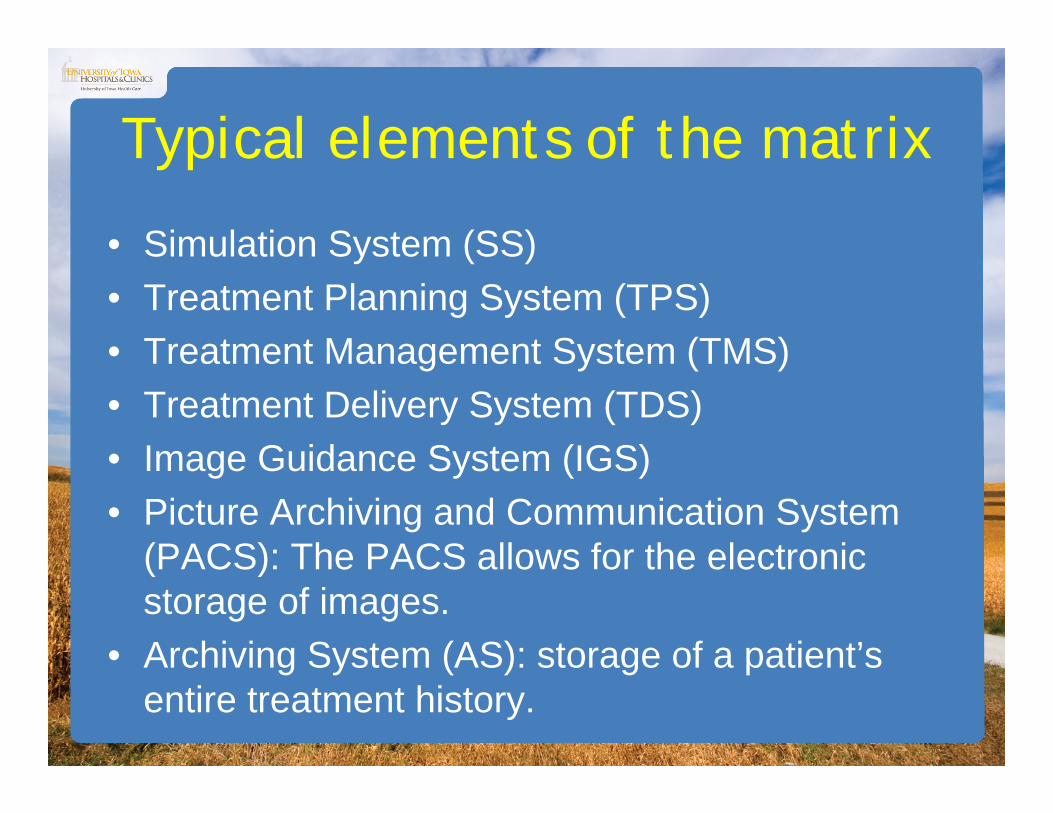
Typical elements of the matrix
• Simulation System (SS)• Treatment Planning System (TPS)• Treatment Management System (TMS)• Treatment Delivery System (TDS)• Image Guidance System (IGS)• Picture Archiving and Communication System
(PACS): The PACS allows for the electronic storage of images.
• Archiving System (AS): storage of a patient’s entire treatment history.

Example Matrix
Table I: An example data transfer matrix. The row and column headers provide the source and destination
subsystems, respectively. The matrix element at a row and column intersection contains the data to be
transferred.
Destination
Source SS TPS TMS TDS AS
SS Images Images
TPS Plan, Images Plan, Images
TMS RT Plan-fields Database backup
TDS Recorded treatment
AS Images Plan, Images Database backup

Testing
• Every cell in the data transfer matrix needs to be tested
• Some parts of tests could be used to test many cells (e.g. cells in the same row)
• Design efficient tests to exploit common features

Quality Assurance and Control Basics
• Principal concepts: – Physical Integrity– Logical Consistency
• ATP and Commissioning• Annual• Patient QC

Principal Concepts• Data Integrity
– Are the bits and bytes intact?– Typically checked with a CRC– Were the transferred bits interpreted as
the correct information?• Logical Consistency
– Are related pieces of information consistent with each other?

ATP and Commissioning
• ATP – typically done with the vendor– Might be limited to subsystem– Make sure to specify data transfer testing as
part of the ATP at time of purchase• Commissioning
– Where data becomes information– Typically enter coordinate systems,
preferences– Test data transfer matrix row for the
subsystem

Annual
• Somewhat of a misnomer• Should really be done anytime a system is
changed• If none of your systems change after a
year, just test hardware for functionality/efficiency
• Might be a good idea to hold off on software updates until several can be combined

Testing: Quality Assurance
• System Tests• equipment meets specs• Given input produces expected
output

Can you really dial 999?

Quality Control
• Inspects each service• Or intermediate product• Or items on an assembly line• What we generally refer to mistakenly as
QA in “patient-specific QA”
Testing: Quality ControlCaffeinated Jelly Bean
Inspector

Data Transfer QC
• Done for every patient• Done for every transfer of data• Check for Logical Consistency and
Data/Information Integrity.

Information Integrity
• Generally a manual check• Some places have automated
systems

Manual vs Automated Check
TPSTMS
Manual Comparison of Printouts or Screens
Software Compares Data Sources
TMS TPS

Logical Consistency
• Mostly manual process• Can be automated to some extent• Example: a prescription calls for a
treatment using 6x, but there is a 10x treatment beam within the prescription

63
Clinical Interactions,
paperless checks
Adapted from Fig 5. Siochi, et al. Radiation therapy plan checks in a paperless clinic, J. App. Clin. Med. Phys., 10(1):43-62.
PhysicistsDosimetrists/Physicians
Therapists
In-House Software

Thank you!