cricket 8-vsb users guide - hug-ct8vsb-001
DESCRIPTION
IneoQuest Cricket 8 Users GuideTRANSCRIPT

HUG-CT8VSB-001October 7, 2009
Cricket™ 8-VSB
User’s Guide

Notice
The information in this guide is subject to change without notice.
INEOQUEST TECHNOLOGIES, INCORPORATED shall not be liable for technical or editorial errors or omissions contained herein; nor for incidental or consequential damages resulting from the furnishing, performance, or use of this material.
ALL STATEMENTS, INFORMATION, AND RECOMMENDATIONS IN THIS DOCUMENT ARE BELIEVED TO BE ACCURATE BUT ARE PRESENTED WITHOUT WARRANTY OF ANY KIND, EXPRESS OR IMPLIED. USERS MUST TAKE FULL RESPONSIBILITY FOR THEIR APPLICATION OF ANY PRODUCTS.
This guide contains information protected by copyright. No part of this guide may be photocopied or reproduced in any form without prior written consent from IneoQuest Technologies, Inc.
The software described in this guide is furnished under a license agreement or nondisclosure agreement. The software may be used or copied only in accordance with the terms of the agreement.
Product names mentioned herein may be trademarks and/or registered trademarks of their respective companies.
© 2009 IneoQuest Technologies, Incorporated. All Rights Reserved.
IneoQuest Technologies, Inc., 170 Forbes Boulevard, Mansfield, Massachusetts 02048 USA
Patent No.: US 7,321,565, B2 and other patents pending
The following are trademarks of IneoQuest Technologies, Inc.:
IneoQuest Technologies, Singulus, iVMS, IQDVx, IQMediaStim, IQTsxPro, IQMediaAnalyzer Pro, Cricket, 8-VSB, Cricket QAM DT, iCMS, IQDialogue, IQPinPoint, IQWatch, RVL, IQtv, IQMediaMonitor, Geminus, Get the Picture, Multi-Dimensional Video Quality Monitoring, Revenue Assurance, IQVisionProbe, IQRouterTest, SmartVIEW, IQMediaMonitor100 and IQMediaSentry
Microsoft and Windows are registered trademarks of Microsoft Corporation.

Contents
1 Technical Support Information1.1 Address and Telephone Numbers.................................................................................................. 1-11.2 Internet Addresses .......................................................................................................................... 1-11.3 About this Document ...................................................................................................................... 1-1
2 General Safety Information2.1 Safety Terms .................................................................................................................................... 2-12.2 General Precautions to Avoid Injury.............................................................................................. 2-12.3 General Precautions to Avoid Property Damage.......................................................................... 2-2
3 Introduction3.1 Overview of the Cricket™ 8-VSB ................................................................................................... 3-1
3.1.1 Features .................................................................................................................................................... 3-13.2 Scope of this Document ................................................................................................................. 3-23.3 Hardware and Software Requirements.......................................................................................... 3-2
4 Technical Specifications4.1 Power and Cooling .......................................................................................................................... 4-14.2 Reference Clock and Calibration ................................................................................................... 4-14.3 Environmental.................................................................................................................................. 4-24.4 Regulatory Information ................................................................................................................... 4-24.5 Relevant Standards Compliance.................................................................................................... 4-34.6 Dimensions and Weight .................................................................................................................. 4-44.7 IneoQuest Part Numbers ................................................................................................................ 4-44.8 Cleaning the Cricket 8-VSB ............................................................................................................ 4-5
5 Installation of the Cricket 8-VSB5.1 Installation of the USB Driver ......................................................................................................... 5-15.2 Cricket 8-VSB Hardware Installation.............................................................................................. 5-1
5.2.1 Cricket 8-VSB Hardware Installation Instructions .................................................................................. 5-35.3 Connecting to the HTML Interface via the USB Port .................................................................... 5-55.4 Configuring the Management Port (TCP/IP) through Port Config............................................... 5-7
5.4.1 Configuring the Management Port with Static IP Addressing................................................................. 5-95.4.2 Configuring the Management Port to use Dynamic Host Configuration Protocol (DHCP) ................... 5-9
6 Configuration of the Cricket 8-VSB and System Status6.1 Connecting and Logging into the Cricket with a Web Browser .................................................. 6-16.2 System Status .................................................................................................................................. 6-3
7 Network Statistics7.1 RF Flow Census............................................................................................................................... 7-17.2 RF Flow Status................................................................................................................................. 7-37.3 RF Flow Program View.................................................................................................................... 7-37.4 RF Tuner Status ............................................................................................................................... 7-57.5 Program Guide................................................................................................................................. 7-57.6 Alarm Log......................................................................................................................................... 7-6
Cricket 8-VSB User’s Guide — HUG-CT8VSB-001 i

8 System Configuration8.1 RF Tuner Config ............................................................................................................................... 8-18.2 RF Tuner Parameters....................................................................................................................... 8-48.3 RF Tuner Channels .......................................................................................................................... 8-68.4 RF Tuner Map ................................................................................................................................... 8-7
8.4.1 Download: From Host to the Cricket ....................................................................................................... 8-88.4.2 Download: From Host to the Cricket ..................................................................................................... 8-10
8.5 Port Config ..................................................................................................................................... 8-108.6 System Management Config......................................................................................................... 8-138.7 User Accounts................................................................................................................................ 8-178.8 Network Ports................................................................................................................................. 8-198.9 Date & Time .................................................................................................................................... 8-218.10 RVL Config ..................................................................................................................................... 8-248.11 Remote Control Config.................................................................................................................. 8-25
9 Monitor Configuration9.1 Global Alarms .................................................................................................................................. 9-19.2 Global Parameters ........................................................................................................................... 9-49.3 Capture ............................................................................................................................................. 9-6
10 Aliases & Templates10.1 Channel Alias ................................................................................................................................. 10-110.2 Video Program Alias...................................................................................................................... 10-310.3 Video/Program Alarm Template.................................................................................................... 10-510.4 Video Transport Alarm Template................................................................................................ 10-11
10.4.1 Transport Stream .................................................................................................................................. 10-1310.4.2 ETSI TR 101 290.................................................................................................................................. 10-18
11 Configuration Management11.1 Download/Upload Configuration.................................................................................................. 11-1
11.1.1 Download Configuration: From Host to the Cricket 8-VSB.................................................................. 11-211.1.1.1 Send this file: ........................................................................................................................... 11-2
11.1.2 Upload Configuration to the Host from the Cricket 8-VSB................................................................... 11-311.1.2.1 Upload System Config File...................................................................................................... 11-311.1.2.2 Upload AliasConfig Text File .................................................................................................. 11-611.1.2.3 Upload Syslog File................................................................................................................... 11-811.1.2.4 Upload Syslog And Clear Log ............................................................................................... 11-1011.1.2.5 Upload Flow Statistics ........................................................................................................... 11-12
11.2 Download Firmware..................................................................................................................... 11-1411.2.0.1 Download Firmware .............................................................................................................. 11-15
11.3 Saving the Configuration ............................................................................................................ 11-1811.3.1 Save Configuration............................................................................................................................... 11-1911.3.2 Save Configuration and Reset System ................................................................................................. 11-1911.3.3 Reset System ........................................................................................................................................ 11-1911.3.4 Switch to Maintenance Mode............................................................................................................... 11-2011.3.5 Reset to Factory Defaults ..................................................................................................................... 11-20
12 Diagnostic Information12.1 Manufacturing Information ........................................................................................................... 12-112.2 System Debug Statistics ............................................................................................................... 12-1
12.2.1 Upload the Error Log.............................................................................................................................. 12-212.2.2 Reset Statistics........................................................................................................................................ 12-5
12.3 RMON Statistics ............................................................................................................................. 12-512.4 Round Trip Time............................................................................................................................. 12-6
ii Cricket 8-VSB User’s Guide — HUG-CT8VSB-001

12.5 Trace Route .................................................................................................................................... 12-8
Appendix A Supported and Unsupported ASCII CharactersA.1 Unsupported Characters ................................................................................................................A-1A.2 Supported Characters .....................................................................................................................A-1
Glossary of Terms ........................................................................................................................................ GL-1
Index .......................................................................................................................................................... Index-1
Cricket 8-VSB User’s Guide — HUG-CT8VSB-001 iii

iv Cricket 8-VSB User’s Guide — HUG-CT8VSB-001

List of Figures
Figure 5-1: Cricket 8-VSB Front Panel ......................................................................................... 5-2Figure 5-2: Cricket 8-VSB Rear Panel .......................................................................................... 5-3Figure 5-3: Secure the Power Cable .............................................................................................. 5-4Figure 5-4: Enter the Default IP Address “10.0.0.2”..................................................................... 5-5Figure 5-5: Cricket Login Page ..................................................................................................... 5-6Figure 5-6: Cricket 8-VSB Home Page ......................................................................................... 5-7Figure 5-7: Select “System Configuration” ................................................................................... 5-8Figure 5-8: Select “Port Config” ................................................................................................... 5-8Figure 5-9: Static IP Addressing Example .................................................................................... 5-9Figure 5-10: Example System Configuration Page ..................................................................... 5-10Figure 6-1: Enter the Configured IP Address ................................................................................ 6-1Figure 6-2: Cricket Login Page ..................................................................................................... 6-2Figure 6-3: Cricket 8-VSB Home Page ......................................................................................... 6-2Figure 6-4: Example System Status Page ...................................................................................... 6-9Figure 7-1: RF Flow Census Example Page.................................................................................. 7-2Figure 7-2: RF Flow Status Example Page.................................................................................... 7-3Figure 7-3: RF Flow Program View Example Page ...................................................................... 7-4Figure 7-4: RF Tuner Status Example Page .................................................................................. 7-5Figure 7-5: Program Guide Example Page .................................................................................... 7-6Figure 7-6: Alarm Log Example Page ........................................................................................... 7-7Figure 8-1: Example Tuner Configuration Page............................................................................ 8-4Figure 8-2: Example Tuner Parameters Page ................................................................................ 8-6Figure 8-3: Example Tuner RF Channels Page ............................................................................. 8-7Figure 8-4: Example Tuner Map Upload/Download Page ............................................................ 8-8Figure 8-5: “File Download” window ........................................................................................... 8-8Figure 8-6: Host location to save map file..................................................................................... 8-9Figure 8-7: “Download Complete” window.................................................................................. 8-9Figure 8-8: Locate the file on the host ......................................................................................... 8-10Figure 8-9: Example Port Configuration Page ............................................................................ 8-12Figure 8-10: Example System Management Configuration Page ............................................... 8-17Figure 8-11: Example User Account Configuration Page ........................................................... 8-19Figure 8-12: Example Network Ports Configuration Page .......................................................... 8-21Figure 8-13: Example Date & Time Configuration Page ............................................................ 8-23Figure 8-14: Example RVL Configuration Page ......................................................................... 8-25Figure 8-15: Example Remote Control Configuration Page ....................................................... 8-27Figure 9-1: Example Global Alarm Configuration Page ............................................................... 9-3Figure 9-2: Example Global Parameters Configuration Page ....................................................... 9-6Figure 9-3: Example Capture Configuration Page ...................................................................... 9-12Figure 10-1: Example RF Channel Alias Page ............................................................................ 10-3Figure 10-2: Example Video Program Alias Names Page .......................................................... 10-5
Cricket 8-VSB User’s Guide — HUG-CT8VSB-001 v

Figure 10-3: Example Video/Program Alarm Template Page................................................... 10-11Figure 10-4: Example Video/Program Transport Flow Alarm Template Page......................... 10-13Figure 10-5: Example Video/Program Transport Stream Alarm Template Page...................... 10-18Figure 10-6: Example Video Transport ETSI Alarm Template Page........................................ 10-20Figure 11-1: Example Download/Upload Configuration Page.................................................... 11-2Figure 11-2: Locate the File on the Host ..................................................................................... 11-3Figure 11-3: “File Download” Window ...................................................................................... 11-4Figure 11-4: Host Location to Save Config File.......................................................................... 11-5Figure 11-5: “Download Complete” Window ............................................................................. 11-6Figure 11-6: Save the AliasConfig File ....................................................................................... 11-6Figure 11-7: Locate the Area to Save the AliasConfig File ........................................................ 11-7Figure 11-8: “Download Complete” Window ............................................................................. 11-8Figure 11-9: Save the Syslog File................................................................................................ 11-8Figure 11-10: “Save As” Window ............................................................................................... 11-9Figure 11-11: “Download Complete” Window ......................................................................... 11-10Figure 11-12: “File Download” Window .................................................................................. 11-10Figure 11-13: “Save As” Window ............................................................................................. 11-11Figure 11-14: “Download Complete” Window ......................................................................... 11-12Figure 11-15: “File Download” Window .................................................................................. 11-13Figure 11-16: “Save As” Window ............................................................................................. 11-13Figure 11-17: “Download Complete” Window ......................................................................... 11-14Figure 11-18: “Firmware Download” Page ............................................................................... 11-15Figure 11-19: Locate the Firmware File to Download .............................................................. 11-16Figure 11-20: “Firmware Update” Page .................................................................................... 11-17Figure 11-21: “Firmware Update” Page Displays Update Progress.......................................... 11-18Figure 11-22: Save Configuration Menu ................................................................................... 11-19Figure 12-1: Manufacturing Information Page ............................................................................ 12-1Figure 12-2: Example System Debug Statistics Page.................................................................. 12-2Figure 12-3: “File Download” Window ...................................................................................... 12-3Figure 12-4: “Save As” Window ................................................................................................. 12-4Figure 12-5: “Download Complete” Window ............................................................................. 12-5Figure 12-6: Example RMON Statistics Page ............................................................................. 12-6Figure 12-7: Example Round Trip Time Page............................................................................. 12-7Figure 12-8: Round Trip Time Page Results ............................................................................... 12-8Figure 12-9: Example Trace Route Page ..................................................................................... 12-9Figure 12-10: Trace Route Page Results ..................................................................................... 12-9
vi Cricket 8-VSB User’s Guide — HUG-CT8VSB-001

List of Tables
Table 4-1: Power and Cooling ....................................................................................................... 4-1Table 4-2: Reference Clock and Calibration ................................................................................. 4-1Table 4-3: Environmental .............................................................................................................. 4-2Table 4-4: Regulatory Information ................................................................................................ 4-2Table 4-5: Relevant Standards Compliance................................................................................... 4-3Table 4-6: Physical ........................................................................................................................ 4-4Table 4-7: IneoQuest Part Numbers .............................................................................................. 4-4Table 6-1: System Status Fields..................................................................................................... 6-3Table 6-2: SNMP Configuration Fields......................................................................................... 6-4Table 6-3: iVMS Configuration Fields .......................................................................................... 6-4Table 6-4: iVMS Firewall Communications Fields....................................................................... 6-5Table 6-5: Syslog Configuration Fields......................................................................................... 6-5Table 6-6: Port Configuration Fields ............................................................................................. 6-6Table 6-7: Global Parameters Fields ............................................................................................. 6-7Table 6-8: Tuner Configuration Fields .......................................................................................... 6-8Table 8-1: Tuner Configuration Fields and Ranges....................................................................... 8-2Table 8-2: Map Fields and Descriptions........................................................................................ 8-5Table 8-3: Management Port Fields and Ranges ......................................................................... 8-11Table 8-4: System Identification Fields and Ranges ................................................................... 8-13Table 8-5: System Memo Field and Range ................................................................................. 8-13Table 8-6: System Location Fields and Valid Ranges................................................................. 8-14Table 8-7: SNMP Configuration Fields and Ranges ................................................................... 8-14Table 8-8: SYSLOG Configuration Fields and Ranges............................................................... 8-15Table 8-9: iVMS Configuration Fields and Ranges .................................................................... 8-15Table 8-10: Defined Users Fields and Ranges............................................................................. 8-18Table 8-11: New Account Fields and Ranges ............................................................................. 8-18Table 8-12: HTTP Fields and Ranges.......................................................................................... 8-20Table 8-13: Telnet Fields and Ranges ......................................................................................... 8-20Table 8-14: ICMP Field and Range ............................................................................................. 8-20Table 8-15: IQ Tools Field and Valid Range .............................................................................. 8-21Table 8-16: Current Field and Range .......................................................................................... 8-22Table 8-17: Time Source Fields and Ranges ............................................................................... 8-22Table 8-18: Adjustments Fields and Ranges ............................................................................... 8-23Table 8-19: RVL Configuration Field and Range ....................................................................... 8-24Table 8-20: Remote Codes .......................................................................................................... 8-26Table 8-21: Remote Control Mode .............................................................................................. 8-27Table 8-22: AUX Function Setup Code ...................................................................................... 8-27Table 9-1: General Field and Range .............................................................................................. 9-2Table 9-2: Alarms Field and Range ............................................................................................... 9-2Table 9-3: Flow Census Fields and Ranges................................................................................... 9-4
Cricket 8-VSB User’s Guide — HUG-CT8VSB-001 vii

Table 9-4: Transport Streams Fields and Ranges .......................................................................... 9-5Table 9-5: Triggers Fields and Ranges .......................................................................................... 9-7Table 9-6: Port Filters Fields and Ranges...................................................................................... 9-8Table 9-7: Program Filters Fields and Ranges............................................................................... 9-9Table 9-8: PID Filters Fields and Ranges ...................................................................................... 9-9Table 9-9: Status Fields and Ranges.............................................................................................. 9-9Table 9-10: Control Fields and Ranges ....................................................................................... 9-10Table 9-11: Upload Field and Range ........................................................................................... 9-11Table 9-12: Auto Upload Fields and Ranges............................................................................... 9-11Table 10-1: RF Flow Alias Template Fields and Ranges ............................................................ 10-2Table 10-2: Characteristics Fields and Ranges............................................................................ 10-2Table 10-3: Program Alias Name Field and Range ..................................................................... 10-4Table 10-4: Video Program Alias Names Fields and Ranges ..................................................... 10-4Table 10-5: Program Monitoring Template Fields and Ranges .................................................. 10-5Table 10-6: Video/Program Alarm Template Fields and Ranges................................................ 10-6Table 10-7: Program Media Loss (CC) Alarms Fields and Ranges ............................................ 10-7Table 10-8: Program Monitoring Alarms Fields and Ranges...................................................... 10-8Table 10-9: Video/Program Alarm Template Fields and Ranges................................................ 10-9Table 10-10: Program PID Bitrate Monitoring Alarms Fields and Ranges .............................. 10-10Table 10-11: Video Transport Alarm Template Fields and Ranges .......................................... 10-12Table 10-12: Video Transport Flow Alarm Template Fields and Ranges................................. 10-12Table 10-13: Video Transport Stream Alarm Template Fields and Ranges.............................. 10-14Table 10-14: Video Transport ETSI TR 101 290 Alarm Template Fields and Ranges ............ 10-18Table 12-1: RMON Statistics ...................................................................................................... 12-5Table 12-2: Round Trip Time...................................................................................................... 12-7Table A-1: Unsupported ASCII Characters.................................................................................. A-1Table A-2: Supported ASCII Characters ...................................................................................... A-2
viii Cricket 8-VSB User’s Guide — HUG-CT8VSB-001

Technical Support Information
1 Technical Support Information
Updated documentation, software and information for this and other products are available on the IneoQuest Web site.
1.1 Address and Telephone Numbers
Address, USA:IneoQuest Technologies Inc.170 Forbes Blvd.Mansfield, MA02048
Telephone, USA:+1 508 339 2497
FAX Telephone Number, USA+1 508 339 4727
Toll-Free Technical Support Telephone, USA:+1 866 464 4636
1.2 Internet Addresses
E-Mail:[email protected]
URL:http://www.ineoquest.com
FTP Server:ftp3.ineoquest.com
1.3 About this Document
This document is intended as a User’s Guide for the Cricket™ 8-VSB. For information regarding any other of IneoQuest’s products, please consult the appropriate document.
Cricket 8-VSB User’s Guide — HUG-CT8VSB-001 1-1

Technical Support InformationTechnical Support Information
1-2 Cricket 8-VSB User’s Guide — HUG-CT8VSB-001

General Safety Information
2 General Safety Information
Observe all safety precautions listed within this document to avoid injury and prevent damage to this product or any product connected to it. To avoid any hazardous conditions, use this product only as specified.
2.1 Safety Terms
Safety statements throughout this document are identified as follows:
WARNINGWarning statements indicate conditions that could result in injury or loss of life and describe how to avoid them.
CAUTIONCaution statements indicate conditions that could result in damage to this product or other property and describe how to avoid these problems.
2.2 General Precautions to Avoid Injury
WARNINGDo not operate in wet or damp environments or outside recommended operating conditions. This product is intended for indoor use.
WARNINGUse only the power supply specified for this product with a properly grounded power outlet.
WARNINGDo not operate this product in an explosive atmosphere.
WARNINGDo not operate this product if it is damaged. Have a qualified service person inspect damaged equipment before use.
WARNINGThis test system is designed to be used for test, monitoring and analysis of network equipment and systems. It is not intended to be used as a part of any life support system, safety system or critical communications link.
Cricket 8-VSB User’s Guide — HUG-CT8VSB-001 2-1

General Safety InformationGeneral Safety Information
2.3 General Precautions to Avoid Property Damage
CAUTIONExcessive electrostatic discharge may damage some components. Take precautions against electrostatic discharge.
CAUTIONUse care in handling. Delicate connectors can be easily damaged.
CAUTIONProvide proper ventilation to prevent the product from overheating.
CAUTIONThis test system is designed to be used for test, monitoring and analysis of network equipment and systems. It is not intended to be used as a part of any life support system, safety system or critical communications link.
2-2 Cricket 8-VSB User’s Guide — HUG-CT8VSB-001

Introduction
3 Introduction
3.1 Overview of the Cricket™ 8-VSB
Cricket™ 8-VSB is a powerful and cost-effective video quality and service assurance tool for broadcasters needing to audit, monitor, analyze and troubleshoot their 8-VSB digital terrestrial service. The Cricket 8-VSB has a unique ability to monitor and report on the physical layer characteristics, such as Reed-Solomon errors, while simultaneously reporting on the MPEG-2 transport stream layer. This allows the Broadcasters to easily isolate any transmission problems from encoder or multiplexer. The Cricket 8-VSB can be deployed at the transmission site and at the corresponding receiver sites to perform service auditing, monitoring and analysis.
The Cricket 8-VSB contains a single RF Tuner which can be configured to continuously scan a sequence of RF channels or tune to a specific frequency to monitor and report on any customer affecting problems, such as loss events, outage, bit-rate variation, PCR clock variation, and TR 101 290 errors. The Cricket also provides physical layer monitoring for errors such as Reed-Solomon corrected and uncorrected errors. By default, it scans the North American standard terrestrial frequency range of 53 MHz to 857MHz. Custom configured frequency maps are also supported within the Cricket 8-VSB.
3.1.1 Features• Reports signal-to-noise ratio and Reed-Solomon errors, corrected and uncorrected
• Real-time monitoring and measurements of video programs
• Auto scan and discovery of VSB RF frequencies
• Tunes to any UHF/VHF channel
• Monitoring and analysis to the PID level
• Remote video verification with IQtv
• Supports SD and HD video content over SPTS and MPTS
• Video trigger / capture
• Seamless integration into iVMS
• Customizable RF Frequency maps and alarm thresholds
• USB connector for local management with PC
• 10/100 MB Fast Ethernet management interface
• Field upgradeable
Cricket 8-VSB User’s Guide — HUG-CT8VSB-001 3-1

IntroductionIntroduction
3.2 Scope of this Document
This document is intended to be a user’s guide for the operation of the Cricket 8-VSB. It includes some hardware information, basic setup, and troubleshooting digital video quality issues. For more comprehensive information on features and troubleshooting with the Cricket 8-VSB please see the IneoQuest Web site www.ineoquest.com or contact IneoQuest Technical Operations at 1-866-464-4636.
3.3 Hardware and Software Requirements
To operate the Cricket 8-VSB, a PC is required with a Web browser such as Windows Internet Explorer or Mozilla Firefox installed.
3-2 Cricket 8-VSB User’s Guide — HUG-CT8VSB-001

Technical Specifications
4 Technical Specifications
4.1 Power and Cooling
4.2 Reference Clock and Calibration
Table 4-1: Power and Cooling
Description Specification
Power Requirements - External Power Supply
Mains Supply:
100 to 240VAC, 0.6A, 50 to 60Hz, voltage fluctuations up to +/- 10% of the nominal voltage.
The power supply contains no user serviceable parts and must not be disassembled.
Power Requirements – Cricket 8-VSB 5 volts DC, 1.9 A via external power adapter or Rack Mount Kit
Power Output to USB Host Port (type A connector)
5 volts DC, 0.5A MAX.
Cooling The Cricket enclosure and power supply are cooled by natural convection. Do not cover or stack units.
Table 4-2: Reference Clock and Calibration
Description Specification
Internal Reference Clock 25 MHz +/- 50ppm accuracy
Calibration The Cricket requires no periodic calibration adjustments during its lifetime.
Cricket 8-VSB User’s Guide — HUG-CT8VSB-001 4-1
Technical SpecificationsTechnical Specifications
4.3 Environmental
4.4 Regulatory Information
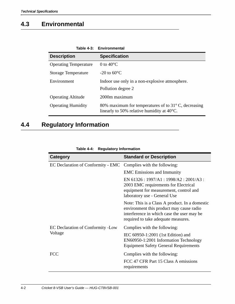
Table 4-3: Environmental
Description Specification
Operating Temperature 0 to 40°C
Storage Temperature -20 to 60°C
Environment Indoor use only in a non-explosive atmosphere.
Pollution degree 2
Operating Altitude 2000m maximum
Operating Humidity 80% maximum for temperatures of to 31° C, decreasing linearly to 50% relative humidity at 40°C.
Table 4-4: Regulatory Information
Category Standard or Description
EC Declaration of Conformity - EMC Complies with the following:
EMC Emissions and Immunity
EN 61326 : 1997/A1 : 1998/A2 : 2001/A3 : 2003 EMC requirements for Electrical equipment for measurement, control and laboratory use - General Use
Note: This is a Class A product. In a domestic environment this product may cause radio interference in which case the user may be required to take adequate measures.
EC Declaration of Conformity -Low Voltage
Complies with the following:
IEC 60950-1:2001 (1st Edition) and EN60950-1:2001 Information Technology Equipment Safety General Requirements
FCC Complies with the following:
FCC 47 CFR Part 15 Class A emissions requirements
4-2 Cricket 8-VSB User’s Guide — HUG-CT8VSB-001

Technical Specifications
4.5 Relevant Standards Compliance
The Cricket 8-VSB is compliant to the relevant sections of the following standards.
Product Safety CSA Listed file # 230516
Complies with the following:
UL 60950-1, 1st edition – Information Technology Equipment - Safety - Part 1: General Requirements
CAN/CSA C22.2 No. 60950-1-03 – Information Technology Equipment - Safety - Part 1: General Requirements.
Table 4-5: Relevant Standards Compliance
IEEE 802.3-2002, IEEE Standard for Information technology--Telecommunications and information exchange between systems--Local and metropolitan area networks--Specific requirements--Part 3: Carrier Sense Multiple Access with Collision Detection (CSMA/CD) Access Method and Physical Layer Specifications.
A/53: ATSC Digital Television Standard, Parts 1 - 6, 2007 as published by the Advanced Television Systems Committee, 1750 K Street, N.W., Suite 1200, Washington, D.C. 20006
Table 4-4: Regulatory Information
Category Standard or Description
Cricket 8-VSB User’s Guide — HUG-CT8VSB-001 4-3

Technical SpecificationsTechnical Specifications
4.6 Dimensions and Weight
4.7 IneoQuest Part Numbers
Table 4-6: Physical
Description Specification
Cricket 8-VSB Dimensions Width: 5.3” (134.6mm)
Height: 2.12” (53.9mm)
Depth: 7” (178mm)
Power Supply Dimensions Width: 1.96” (50mm)
Height: 1.23” (31.2mm)
Depth: 4.33” (110mm)
Weight 0.75 kg (1.65 lbs)
1.27 kg (2.80 lbs) - with external power supply and power cord
Table 4-7: IneoQuest Part Numbers
IneoQuest Part Number Description
950-00012-002 Power Supply, 5V 20W
870-00016-001 Power Cord, North America
870-00016-002 Power Cord, UK
870-00016-003 Power Cord, Europe
870-00016-004 Power Cord, Israel
870-00016-005 Power Cord, Japan
870-00016-006 Power Cord, Swiss
870-00045-001 USB Cable, A - MiniB
870-00083-001 Serial Cable, DB9-RJ12
4-4 Cricket 8-VSB User’s Guide — HUG-CT8VSB-001
Technical Specifications
4.8 Cleaning the Cricket 8-VSB
External surfaces may be cleaned using a clean cloth dampened with water or 70% isopropyl alcohol.
Cricket 8-VSB User’s Guide — HUG-CT8VSB-001 4-5

Technical SpecificationsTechnical Specifications
4-6 Cricket 8-VSB User’s Guide — HUG-CT8VSB-001

Installation of the Cricket 8-VSB
5 Installation of the Cricket 8-VSB
Before attempting to set up the hardware, ensure that you received the following items with your shipment:
• Cricket Chassis
• 1, 5V Power Supply
• 1, Power Cord (Regional Specific)
• 1, CD-ROM containing USB driver, and documentation
• 1, USB cable
In order to configure and use the Cricket it must be correctly connected. The network connection (blinking Link LED prior to connecting) or the Mini B type USB port can be used as the management port. Use the following figures and explanations to help you connect your system correctly.
Figure 5-1 shows the front panel of the Cricket 8-VSB. Figure 5-2 shows the rear panel. The figures include reference numbers that correspond with the descriptions that follow.
5.1 Installation of the USB Driver
These are the basic instructions for installing the USB driver software on the host computer.
NOTE: The USB Driver must be installed before you connect the Cricket to the PC via the USB cable. If the Cricket is connected to the PC via the USB cable and powered up, it could corrupt the installation. Disconnect the USB cable and Cricket from the PC before installing the USB driver.
1. On the installation CD, locate the file, “IneoQuest-USB-install.exe”. Typically, it is located in a “Utilities” folder.
2. Initiate the executable file and install the driver on the host computer.
5.2 Cricket 8-VSB Hardware Installation
In order to properly install the Cricket 8-VSB, familiarize yourself with the location of the connectors identified here then follow the installation steps in this chapter.
Cricket 8-VSB User’s Guide — HUG-CT8VSB-001 5-1

Installation of the Cricket 8-VSBInstallation of the Cricket 8-VSB
Figure 5-1: Cricket 8-VSB Front Panel
The following list describes each of the numbered items on the front and rear panels of the Cricket unit. Refer to the numbered items in Figure 5-1 and Figure 5-2.
(1) Front panel status LEDs:
– Power (Power Indicator) – A green LED means power is on.
– Alarm (Alarm Indicator) – A green LED indicates that no thresholds have been exceeded. A red LED means that thresholds have been exceeded.
– Media (Media Stream Indicator) – This green LED blinks indicating that a frame has been captured into a JPEG image.
– Media Loss (Media Loss Indicator) – This green LED blinks indicating an MDI error has occurred.
(2) Front Panel Viewer Feedback button is used to manually indicate problems with the media stream.
5-2 Cricket 8-VSB User’s Guide — HUG-CT8VSB-001

Installation of the Cricket 8-VSB
Figure 5-2: Cricket 8-VSB Rear Panel
(3) + 5V: DC Power Input connection. Connect the IneoQuest 5V power supply to this port on the back of the Cricket unit.
(4) USB: Chassis System USB (MiniB type) Management Port. Use this port to connect the Cricket unit to your PC for configuration communication with the IQMediaAnalyzer Pro application.
(5) USB: Chassis System host USB (A type) Port.
(6) Primary IP Port: Used to connect Cricket to the DUT. A copper CAT5 cable to the 10/100 RJ45 connector can be used. The default configuration of this port is ARP disabled.
(7) Secondary IP Port: Used when the Cricket is connected in line and passes through the Tx and Rx data. Use a copper CAT5 cable to the 10/100 RJ45 connector.
(8) Cable In: 8-VSB coax connector.
(9) Reset: Used to cause a hardware reset.
5.2.1 Cricket 8-VSB Hardware Installation Instructions
Follow these steps to install the Cricket 8-VSB hardware. Refer to Figure 5-1 and Figure 5-2 if necessary for the identified connection locations.
1. On the rear panel of the Cricket 8-VSB, insert the male end of a coax video cable connector into the “Cable In” jack.
2. Attach an Ethernet cable between the management “Primary Port” of the Cricket to an Ethernet port of the management network.
Cricket 8-VSB User’s Guide — HUG-CT8VSB-001 5-3

Installation of the Cricket 8-VSBInstallation of the Cricket 8-VSB
3. Attach the included +5 Volt power supply to the Cricket. Plug the power supply into a properly grounded power outlet. The Cricket will automatically power up. There are no switches to apply power.
NOTE: When inserting the power supply connector, be sure that the connector is fully inserted. Verify that the power indicator on the front panel is lit after the power supply is connected to a grounded power outlet. If the power indicator is not lit, verify that you have fully seated the power supply connector.
Install a cable tie on the real panel of the Cricket 8-VSB to secure the power cable. Be sure to install the cable tie as shown in Figure 5-3. This method will provide slight inward pressure on the power cable during operation and allow the power jack to be removed without cutting the wire tie.
Figure 5-3: Secure the Power Cable
NOTE: If the Cricket 8-VSB is to be installed in a Cricket Rack Mount, the Cricket will receive power from the Rack Mount. Please refer to the Cricket Rack Mount Kit Installation Guide for the appropriate power connection instructions.
In addition, verify that the Cricket Rack Mount Kit you have is Revision D or higher. The revision number is located on a label with the part number and revision number in the lower left-hand corner on the front of the Rack Mount. Earlier revision numbers may require adjustment in order for the Cricket 8-VSB to fit properly. The power jack on the Cricket 8-VSB will not fit properly if the Rack Mount’s internal distribution board is not adjusted correctly.
If the Rack Mount Kit is not labeled Revision D or higher, carefully check
5-4 Cricket 8-VSB User’s Guide — HUG-CT8VSB-001

Installation of the Cricket 8-VSB
alignment of the power connector when installing the Cricket 8-VSB. The connector should mate without force. If the connector does not line up properly, contact IneoQuest for assistance.
Cricket Rack Mount part numbers are:
IQK-CRKTRCK-001, Cricket Rack Mount Kit, AC
IQK-CRKTRCK-002, Cricket Rack Mount Kit, DC
4. After approximately 60 seconds ensure that the Ethernet “Link” light is lit on the Cricket management port (“Primary Port”).
5.3 Connecting to the HTML Interface via the USB Port
The Cricket 8-VSB uses the rear panel mini USB port for management via a local host computer. The USB 2.0 connection can be used to verify and or change the IP configuration of the System Management Port.
Be sure to verify that the current IP configuration of the System Management Port will work on your network without conflict before continuing. Factory test and burn in settings were shipped with your system. Network configuration methods require the Cricket to be in the operational mode for use with iVMS™.
Follow these instructions to connect to the HTML interface via the USB port.
1. Connect power cabling to the Cricket 8-VSB, and the USB connection to the Cricket 8-VSB and your host computer.
NOTE: Refer to power cabling installation instructions in Section 5.2.1 for the proper power cabling procedure.
2. Use a Web browser application such as Windows Internet Explorer or Mozilla Firefox on a host computer and enter the default IP address “10.0.0.2” (see Figure 5-4).
Figure 5-4: Enter the Default IP Address “10.0.0.2”
Cricket 8-VSB User’s Guide — HUG-CT8VSB-001 5-5

Installation of the Cricket 8-VSBInstallation of the Cricket 8-VSB
3. The Cricket Login Screen will appear (See Figure 5-5). Input username and password. For initial setup the default username is “Admin” and default password is “Su”. The usernames and passwords are case sensitive. After you have entered the username and password, click the “Log On” ( ) button.
Figure 5-5: Cricket Login Page
4. The page will display the Cricket’s “Home” Web page (see Figure 5-6). Now that you are connected to the Cricket via the USB and Web browser, proceed to Section 5.4 for configuring the System Management Port.
5-6 Cricket 8-VSB User’s Guide — HUG-CT8VSB-001

Installation of the Cricket 8-VSB
Figure 5-6: Cricket 8-VSB Home Page
5.4 Configuring the Management Port (TCP/IP) through Port Config
These are the steps to follow when setting up the Port Config. If necessary, please refer to Section 8.5 for setting descriptions and valid ranges.
1. Select “System Configuration” in the left-hand menu section of the HTML interface. See Figure 5-7.
Cricket 8-VSB User’s Guide — HUG-CT8VSB-001 5-7

Installation of the Cricket 8-VSBInstallation of the Cricket 8-VSB
Figure 5-7: Select “System Configuration”
2. Select the “Port Config” menu option in the expanded menu. See Figure 5-8.
Figure 5-8: Select “Port Config”
The Cricket 8-VSB supports either Dynamic Host Configuration Protocol (DHCP) (see Section 5.4.2) or Static IP addressing (see Section 5.4.1).
The Cricket supports the following interface connections: HTML Web browser based direct connection interface or a connection via iVMS™. Instructions on the use of the iVMS are outside the scope of this document. Please refer to the iVMS™ User’s Guide.
5-8 Cricket 8-VSB User’s Guide — HUG-CT8VSB-001
Installation of the Cricket 8-VSB
The system management port of the Cricket allows remote access to the Cricket and faster communication speeds over the USB.
5.4.1 Configuring the Management Port with Static IP Addressing
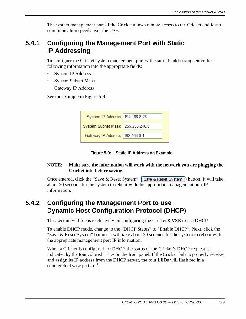
To configure the Cricket system management port with static IP addressing, enter the following information into the appropriate fields:
• System IP Address
• System Subnet Mask
• Gateway IP Address
See the example in Figure 5-9.
Figure 5-9: Static IP Addressing Example
NOTE: Make sure the information will work with the network you are plugging the Cricket into before saving.
Once entered, click the “Save & Reset System” ( ) button. It will take about 30 seconds for the system to reboot with the appropriate management port IP information.
5.4.2 Configuring the Management Port to use Dynamic Host Configuration Protocol (DHCP)
This section will focus exclusively on configuring the Cricket 8-VSB to use DHCP.
To enable DHCP mode, change to the “DHCP Status” to “Enable DHCP”. Next, click the “Save & Reset System” button. It will take about 30 seconds for the system to reboot with the appropriate management port IP information.
When a Cricket is configured for DHCP, the status of the Cricket’s DHCP request is indicated by the four colored LEDs on the front panel. If the Cricket fails to properly receive and assign its IP address from the DHCP server, the four LEDs will flash red in a counterclockwise pattern.1
Cricket 8-VSB User’s Guide — HUG-CT8VSB-001 5-9

Installation of the Cricket 8-VSBInstallation of the Cricket 8-VSB
Once the Cricket has rebooted and obtained an IP address from the DHCP server, you can get the IP address by connecting the USB cable, typing “10.0.0.2” IP address in a browser window, and selecting the “Port Config” menu option in the “System Configuration” section of the HTML interface. The new IP address will be displayed there. See Figure 5-10 for an example.
Figure 5-10: Example System Configuration Page
1. If the Cricket fails to obtain an IP address from DHCP, it can still be accessed locally via the mini-USB 2.0 connector. This requires a PC with a special driver (IneoQuest USB LAN Link) that layers TCP/IP over USB. The local IP address of the Cricket in this scenario is 10.0.0.2.
5-10 Cricket 8-VSB User’s Guide — HUG-CT8VSB-001

Configuration of the Cricket 8-VSB and System Status
6 Configuration of the Cricket 8-VSB and System Status
Configuration of the Cricket hardware is accomplished mainly through the HTML interface. Some of the configuration can also be performed by the iVMS, but this document only describes the HTML interface.
6.1 Connecting and Logging into the Cricket with a Web Browser
After the Cricket system management port has been successfully configured (see Section 5.4), a Web browser such as Windows Internet Explorer (IE) or Mozilla Firefox (Firefox) may be used to access it directly through an Ethernet connection rather than the USB. Ethernet is a faster communication path.
To directly connect to the Cricket follow these steps:
1. Connect power and Ethernet cabling.
2. Use a Web browser application on a host computer and enter the configured IP address, for example: “192.168.8.28” (see Figure 6-1).
Figure 6-1: Enter the Configured IP Address
3. The Cricket Login Page will appear (See Figure 6-2). Input username and password. For initial setup the default username is “Admin” and default password is “Su”. The usernames and passwords are case sensitive. After you have entered the username and password, click the “Log On” ( ) button.
Cricket 8-VSB User’s Guide — HUG-CT8VSB-001 6-1

Configuration of the Cricket 8-VSB and System StatusConfiguration of the Cricket 8-VSB and System Status
Figure 6-2: Cricket Login Page
4. Now, you should be connected to the Cricket via Ethernet and Web Browser. The browser will then open to the Cricket “Home” Web page (see Figure 6-3). Password change (user account management) is available under the “System Configuration” section of the HTML interface (see Section 8 for more information regarding this).
Figure 6-3: Cricket 8-VSB Home Page
6-2 Cricket 8-VSB User’s Guide — HUG-CT8VSB-001

Configuration of the Cricket 8-VSB and System Status
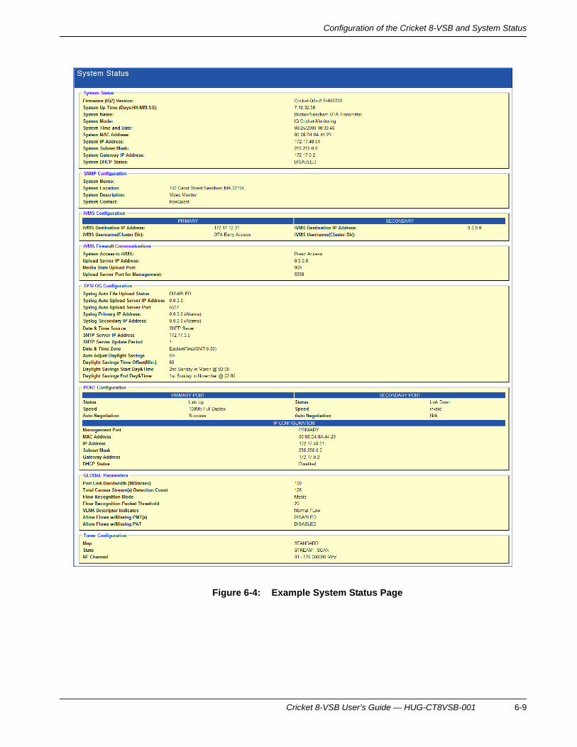
6.2 System Status
The System Status page lists the current configuration settings and port status of the monitoring system. This page includes multiple sections. See Figure 6-4 for an example page.
System Status
See Section 8.5 for information on setting the values in this part of the report, except where noted.
Table 6-1: System Status Fields
Field Description
FIRMWARE (IQZ) VERSION Version of the firmware currently installed and running on the system. See Section 11.2 for information about updating the firmware.
SYSTEM UP TIME (DAYS:HH:MM:SS)
Duration since the last system restart.
SYSTEM NAME Configured name of the system.
SYSTEM MODE Operating mode of the unit.
SYSTEM TIME AND DATE Time and date of the system clock. Used to time stamp state changes and alarms.
Cricket 8-VSB User’s Guide — HUG-CT8VSB-001 6-3

Configuration of the Cricket 8-VSB and System StatusConfiguration of the Cricket 8-VSB and System Status
SNMP Configuration
See Section 8.5 for information on setting the values in this part of the report.
iVMS Configuration
See Section 8.6 for information on setting the values in this part of the report.
SYSTEM MAC ADDRESS Layer 2 address of the system. This value is not configurable.
SYSTEM IP ADDRESS Layer 3 address of the system.
SYSTEM SUBNET MASK Layer 3 subnet mask of the system.
SYSTEM GATEWAY IP ADDRESS Gateway layer 3 address of the system.
SYSTEM DHCP STATUS Setting for Dynamic Host Control Protocol (enabled/disabled).
Table 6-2: SNMP Configuration Fields
Field Description
SYSTEM MEMO This field displays a note or a brief text message.
SYSTEM LOCATION Physical location of the unit.
SYSTEM DESCRIPTION Description of the system.
SYSTEM CONTACT Contact for the system.
Table 6-3: iVMS Configuration Fields
Field Description
IVMS DESTINATION IP ADDRESS Layer 3 address of the iVMS server.
IVMS USERNAME (CLUSTER DIR) Directory for consolidating iVMS data.
Table 6-1: System Status Fields (Continued)
Field Description
6-4 Cricket 8-VSB User’s Guide — HUG-CT8VSB-001

Configuration of the Cricket 8-VSB and System Status
iVMS Firewall Communications
See Section 8.6 for information on setting the values in this part of the report.
SYSLOG Configuration
See Sections 8.5 and 8.9 for information on setting the values in this part of the report.
Table 6-4: iVMS Firewall Communications Fields
Field Description
SYSTEM ACCESS TO IVMS The method used to connect to iVMS.
UPLOAD SERVER IP ADDRESS Layer 3 address of the iVMS upload server.
MEDIA STATS UPLOAD PORT Port address for media stats.
UPLOAD SERVER PORT FOR MANAGEMENT
Port address for upload server management.
Table 6-5: Syslog Configuration Fields
Field Description
SYSLOG AUTO FILE UPLOAD STATUS Enabled or Disabled.
SYSLOG AUTO UPLOAD SERVER IP ADDRESS
Layer 3 address of the Syslog Auto Upload Server.
SYSLOG AUTO UPLOAD SERVER PORT Port Address of the Syslog Auto Upload Server.
SYSLOG PRIMARY IP ADDRESS Layer 3 address for the syslog daemon.
SYSLOG SECONDARY IP ADDRESS Secondary Layer 3 address for the syslog daemon.
DATE & TIME SOURCE Source for the system clock.
SNTP SERVER IP ADDRESS Layer 3 address of the SNTP server.
SNTP SERVER UPDATE PERIOD Duration of wait between requesting time from the SNTP server.
Cricket 8-VSB User’s Guide — HUG-CT8VSB-001 6-5

Configuration of the Cricket 8-VSB and System StatusConfiguration of the Cricket 8-VSB and System Status
Port Configuration
See Section 5.4 for information on setting the values in this part of the report.
DATE & TIME ZONE Time zone where the system is located.
AUTO ADJUST DAYLIGHT SAVINGS Setting of the auto adjust for Daylight Saving Time.
DAYLIGHT SAVINGS TIME OFFSET (MIN.)
Number of minutes to offset the clock during Daylight Saving Time.
DAYLIGHT SAVINGS START DAY & TIME
Date and time that Daylight Saving Time starts.
DAYLIGHT SAVINGS END DAY & TIME Date and time that Daylight Saving Time ends.
Table 6-6: Port Configuration Fields
Field Description
Primary and Secondary Ports
STATUS Status of the link (up/down).
SPEED Speed of the link.
AUTO-NEGOTIATION Success or Failure.
IP Configuration
MANAGEMENT PORT Primary or Secondary.
MAC ADDRESS Layer 2 address for the port. This value is not configurable.
IP ADDRESS Layer 3 address of port 1.
Table 6-5: Syslog Configuration Fields (Continued)
Field Description
6-6 Cricket 8-VSB User’s Guide — HUG-CT8VSB-001

Configuration of the Cricket 8-VSB and System Status
Global Parameters
See Section 9.2 for information on setting the values in this part of the report.
SUBNET MASK Layer 3 subnet mask of port 1.
GATEWAY ADDRESS Layer 3 gateway address for port 1.
DHCP STATUS Enabled or Disabled.
Table 6-7: Global Parameters Fields
Field Description
PORT LINK BANDWIDTH (MBITS/SEC) Display of the Port link bandwidth limit
TOTAL CENSUS STREAM(S) DETECTION COUNT
The maximum number of flow/streams allowed in the census.
FLOW RECOGNITION MODE Mode used for detecting flows
Alias: Only flows with an alias defined are displayed in the census
Media: Only flows detected as a valid media type are displayed in the census
Alias & Media: Only flows that meet both the Alias and Media criteria are displayed in the census.
All: All detected flows are displayed in the census
FLOW RECOGNITION PACKET THRESHOLD
Minimum number of packets in a flow that must be detected for the flow to be displayed in the census
Used only when Recognition Mode is set to All
Table 6-6: Port Configuration Fields (Continued)
Field Description
Cricket 8-VSB User’s Guide — HUG-CT8VSB-001 6-7

Configuration of the Cricket 8-VSB and System StatusConfiguration of the Cricket 8-VSB and System Status
Tuner Configuration
See Section <> for information on setting the values in this part of the report.
VLNK DESCRIPTION INDICATES Determines how flows that contain one or more VLNK descriptors are handled
Normal Flow: Ignores the descriptor
Menu Mode: Causes these flows to be considered menu flows
ALLOWS FLOWS W/MISSING PMT(S) Include flows without a program map table to be displayed in the census
ALLOWS FLOWS W/MISSING PAT Include flows without a program association table to be displayed in the census
Table 6-8: Tuner Configuration Fields
Field Description
MAP Name of the RF tuner map in use
STATE Stream: Tuned to the specified RF channel for analysis
Scan: Currently scanning through the RF channels, tuning to each for analysis
RF CHANNEL For Scan mode: RF channel to start streaming
For Stream/Lock mode: RF channel to lock
Table 6-7: Global Parameters Fields (Continued)
Field Description
6-8 Cricket 8-VSB User’s Guide — HUG-CT8VSB-001
Configuration of the Cricket 8-VSB and System Status
Figure 6-4: Example System Status Page
Cricket 8-VSB User’s Guide — HUG-CT8VSB-001 6-9

Configuration of the Cricket 8-VSB and System StatusConfiguration of the Cricket 8-VSB and System Status
6-10 Cricket 8-VSB User’s Guide — HUG-CT8VSB-001

Network Statistics
7 Network Statistics
Use the Network Statistics pages to monitor the status of flows, programs and alarms.
7.1 RF Flow Census
Flow Census displays program and MDI information for the detected flows. See Figure 7-1 for an example page.
Cricket 8-VSB User’s Guide — HUG-CT8VSB-001 7-1

Network StatisticsNetwork Statistics
The colored columns represent the metrics with a Video Program or Transport alarm threshold set. See Section 10 for information on configuring alarm templates.
The colored LEDs in the Alias Name column reflect the most severe condition in the corresponding row. The first LED represents RF Transport (Flow) alarms and the second LED represents the Program alarm status.
In the census information:
Use the refresh slider in the upper right-hand corner of the page to change the update rate. Full left is off. Full right is roughly once a second. Click the handle of the refresh slider to get an immediate update.
Use the “Clear History” button ( ) in the upper right-hand corner of the page to reset the MDI counters. Use the “Clear Flows” button ( ) to clear all detected flows and re-scan to detect flows.
Figure 7-1: RF Flow Census Example Page
Green cells or LEDs indicate a good state.
Red cells or LEDs indicate the stream is currently in an alarmed state.
Yellow cells or LEDs indicate the stream experienced an alarm in the past 15 minutes.
Black cells or LEDs indicate an outage.
Gray cells or LEDs indicate the stream is not monitored.
7-2 Cricket 8-VSB User’s Guide — HUG-CT8VSB-001

Network Statistics
7.2 RF Flow Status
RF Flow Status displays program and alias information for detected flows, along with error and duration information. See Figure 7-2 for an example page.
See Section 10 for information on configuring alarm templates.
Figure 7-2: RF Flow Status Example Page
Click on any flow to display current detailed statistics in the blue section at the bottom of the page. Use the refresh slider in the upper right corner of the page to change the update rate. Full left is off, and full right is the fastest setting. Click the handle of the slider to get an immediate update. Use the “Reset Stats” button ( ) to clear the statistics.
7.3 RF Flow Program View
RF Flow Program view displays program alarms. See Figure 7-3 for an example page.
Use the “Flow Filter” field to select one or all flows and the “Program” field to select a program.
Cricket 8-VSB User’s Guide — HUG-CT8VSB-001 7-3

Network StatisticsNetwork Statistics
Figure 7-3: RF Flow Program View Example Page
You can select a particular flow by clicking the drop-down indicator on the “Flow Filter” selection field in the upper right corner of the page. This can be used to limit the program list display to programs in a single flow.
Underneath the “Flow Filter” selection field is the Program box which can be used to quickly find an entry in the program list. The Program box can be used either as a simple drop-down list or as a text-input field. This type of input box is referred to as a combobox. Typing in the box will limit the items displayed in the drop-down list to those which match what has been typed. In addition, clicking any item in the program list or in the Program box will cause the program details area to display the details of the selected program.
Program Specific Information (PSI) programs are shown in the program list with a symbol. Every flow has a PSI program which is a collection of transport stream level PIDs, such as Program Association Table (PAT), Network Information Table (NIT), Conditional Access Table (CAT), which do not belong to any one program.
Non-media programs (NMP) are shown in the program list with a symbol. A non-media program is a program containing no audio or video PIDs. A program can also be marked as non-media by selecting the “Non-Media Control Program” checkbox in the video program alias (See Section 10.2).
7-4 Cricket 8-VSB User’s Guide — HUG-CT8VSB-001

Network Statistics
7.4 RF Tuner Status
RF Tuner Status displays the channel/frequency mapping, program information and Reed-Solomon error information. See Figure 7-4 for an example page.
Use the refresh slider in the upper right-hand corner of the page to change the update rate. Full left is off. Full right is roughly once a second. Click the handle of the refresh slider to get an immediate update.
Selectingthe “Clear Counters” button ( ) in the upper right of the page resets Reed-Solomon counts and percentages
NOTE: Reed-Solomon interval counters maintained in a stream census are not reset.
NOTE: Signal status is only displayed if the signal quality is less than nominal.
Figure 7-4: RF Tuner Status Example Page
7.5 Program Guide
Program Guide displays the program/channel. See Figure 7-5 for an example page.
Cricket 8-VSB User’s Guide — HUG-CT8VSB-001 7-5

Network StatisticsNetwork Statistics
Use the refresh slider in the upper right-hand corner of the page to change the update rate. Full left is off. Full right is roughly once a second. Click the handle of the refresh slider to get an immediate update.
You can select the program information to view by using the buttons on the remote control display or clicking a program in the list on the right of the page.
Figure 7-5: Program Guide Example Page
The program list indicates scrambled status using the following color code:
• Blue – Scrambled
• Green – Unscrambled
• Black – Unknown
7.6 Alarm Log
The Alarm Log shows the history of alarms that have been triggered. See Section 10 for information on configuring alarm templates. See Figure 7-6 for an example page.
Use the refresh slider in the upper right-hand corner of the page to change the update rate. Full left is off. Full right is roughly once a second. Click the handle of the refresh slider to get an immediate update.
7-6 Cricket 8-VSB User’s Guide — HUG-CT8VSB-001

Network Statistics
Use the “Clear log” button ( ) to clear the log.
Figure 7-6: Alarm Log Example Page
Cricket 8-VSB User’s Guide — HUG-CT8VSB-001 7-7

Network StatisticsNetwork Statistics
7-8 Cricket 8-VSB User’s Guide — HUG-CT8VSB-001

System Configuration
8 System Configuration
Use the System Configuration pages to set and update the IP configuration of the system management port, manage user accounts, the network ports, and the system date and time. When changing the management port, use the “Save & Reset System” button ( ) in the upper right-hand corner of the page to save changes and reset the test system.
NOTE:If the system IP address is changed you must change the IP address in your browser to reconnect. DO NOT power cycle the system until the system completes the reset process.
8.1 RF Tuner Config
Use the Tuner Configuration page to specify a channel to analyze, or the starting channel to analyze when scanning.
Use the refresh slider in the upper right-hand corner of the page to change the update rate. Full left is off. Full right is roughly once a second. Click the handle of the refresh slider to get an immediate update. See Figure 8-1 for an example page.
Cricket 8-VSB User’s Guide — HUG-CT8VSB-001 8-1

System ConfigurationSystem Configuration
Mode Control
Mode Controls controls RF channel tuning, streaming, scanning, and default mode.Table 8-1: Tuner Configuration Fields and Ranges
Field Description Valid Range
Mode Control
RF Channel Stream/lock mode: RF channel to lock onto
Scan mode: RF channel at which to begin scanning
Use the start and stop buttons ( ) to begin and end streaming and analysis.
Valid channel in the map
STB channel Stream/lock mode: STB channel to lock onto
Scan mode: STB channel at which to begin scanning
Use the start and stop buttons ( ) to begin and end streaming and analysis.
A valid program alias must be defined with the matching STB channel number. The RF channel that contains the STB channel is tuned and streamed.
Scan duration Number of seconds spent streaming each channel. Changes to this parameter only affect the scan once it is started, not while it is currently running, scan time must be greater than or equal to 15 seconds.
Use the scan and quit buttons ( ) to begin and end scanning.
Greater than or equal to 15 seconds
8-2 Cricket 8-VSB User’s Guide — HUG-CT8VSB-001
System Configuration
Detection Control
“Detection Control” controls RF channel discovery. Clicking the “learn” button ( ) initiates a complete scan for QAM digital channels and attempts to discover programs on those channels. All channels are checked regardless of the configuration. The scan may take several minutes to complete.
Alias Configuration
“Alias Configuration” updates the RF alias table with the current detected configuration. Clicking the “save” button ( ) updates the RF alias table with the current detected configuration. Alias updates can performed for “RF channels only” or “RF channels and programs”.
NOTE: After a default mode change or an alias configuration save, a save configuration must be performed from the “Save Config” menu option in “Configuration Management” to ensure changes persist over a reset or power cycle (see Section 11.3).
RF Channel Status Table
The RF Channel Status Table displays the channels detected and the channels with RF aliases defined. Frequency values are the center frequency of the channel's band. A complete list of supported RF channels and frequencies is available at the RF Tuner Channels page (see Section 8.3).
Default mode Scan: Continuously cycle through the channels defined in the RF alias table. Each channel is tuned and streamed for analysis for the number of seconds specified in the Scan duration field.
Stream/lock: Tune, stream and analyze the RF channel specified in the RF channel field.
Set ( ) updates the default mode, duration, and channel parameters. A set must be performed prior to a save configuration. A save configuration must be performed from the “Save Config” page (see Section 11.3) to ensure changes persist over a reset or power cycle.
scan, stream/lock
Table 8-1: Tuner Configuration Fields and Ranges (Continued)
Field Description Valid Range
Cricket 8-VSB User’s Guide — HUG-CT8VSB-001 8-3

System ConfigurationSystem Configuration
The “Programs” column indicates the total number of programs detected in the transport stream and the number of those programs that are scrambled. The number of programs will not be indicated until the transport stream is discovered in census. The “Reed-Solomon %” column displays the percentage of uncorrected/corrected Reed-Solomon errors to the total number of payload bits received.
Figure 8-1: Example Tuner Configuration Page
8.2 RF Tuner Parameters
Use the Tuner Parameters page to specify the frequencies to be used for the channels. Changes applied with the Update button ( ) are lost after a reset or power cycle. See Figure 8-2 for an example page.
NOTE: A device must be reset for changes to take effect. A save configuration must be performed from the “Save Config” menu option in “Configuration Management” to ensure changes persist over a reset or power cycle (see Section 11.3).
Map
“Map” allows you to set the tuner frequency map.
8-4 Cricket 8-VSB User’s Guide — HUG-CT8VSB-001

System Configuration
Automatic Gain Control (AGC)
In this field you can disable or enable AGC. For most installations, the AGC should be disabled.
Table 8-2: Map Fields and Descriptions
Field Description
Standard Uses the channel and frequency allocations defined in the CEA-542-B Cable Television Identification Plan
Custom Enabled when a Tuner Map is downloaded to the Cricket. See “RF Tuner Map” on page -7
Include Custom Map in Config File Upload/Download
Select to save/load a custom map when downloading/downloading configuration files.
If the probe contains a custom frequency map, then the map can optionally be included in the system config file uploaded from the Download/Upload Configuration page (See Section 11.1).
If a system config file contains a custom frequency map, then the map can optionally be saved during a configuration download from the config file uploaded from the Download/Upload Configuration page.
Note that this selection itself is volatile and not included in any saved probe configuration.
Cricket 8-VSB User’s Guide — HUG-CT8VSB-001 8-5

System ConfigurationSystem Configuration
Figure 8-2: Example Tuner Parameters Page
8.3 RF Tuner Channels
Use the Tuner RF Channels page to view a read-only report of the channel map. See Figure 8-3 for an example page.
8-6 Cricket 8-VSB User’s Guide — HUG-CT8VSB-001

System Configuration
Figure 8-3: Example Tuner RF Channels Page
8.4 RF Tuner Map
Use the Tuner Map Upload/Download page (see Figure 7 5) to manage custom channel mappings. See Figure 8-4 for an example page.
To create a custom tuner map file, upload the current map to view the file format. The file contains a single map entry per line in ASCII format. Each map entry contains a channel number and frequency pair tab delimited. The channel number must be between 1 and 255 inclusive with and optional single character prefix. The frequency parameter must be specified in Hertz (Hz).
Cricket 8-VSB User’s Guide — HUG-CT8VSB-001 8-7

System ConfigurationSystem Configuration
Figure 8-4: Example Tuner Map Upload/Download Page
8.4.1 Download: From Host to the Cricket
1. Click the up arrow ( ).
2. A “File Download” window similar to the one in Figure 8-5 will appear.
Figure 8-5: “File Download” window
8-8 Cricket 8-VSB User’s Guide — HUG-CT8VSB-001

System Configuration
3. Click the “Save” button. Locate the area on the host where you want to save the configuration file. See Figure 8-6 for an example.
Figure 8-6: Host location to save map file
4. Click the “Save” button.
5. Depending on your host's settings, a “Download Complete“ window similar to the one in Figure 8-7 will appear.
Figure 8-7: “Download Complete” window
6. Click the “Close” button.
Cricket 8-VSB User’s Guide — HUG-CT8VSB-001 8-9

System ConfigurationSystem Configuration
8.4.2 Download: From Host to the Cricket
1. Click the “Browse” button to locate the host file to download.
2. Identify the tuner map file on the host that will be downloaded to the Cricket. (See Figure 8-8 for an example.)
Figure 8-8: Locate the file on the host
3. Click the file name and then click “Open”. The file name will appear in the “Send this file:” field on the Cricket’s “Download” Web page.
4. Click the “Download” button on the Cricket Web page to initiate the download.
8.5 Port Config
The Cricket 8-VSB has:
• User defined settings for system IP configuration for the management port, including port assignment and optional DHCP configuration.
NOTE: If the system IP address is changed you must change the IP address in your browser to reconnect. DO NOT Power cycle the system until the system completes the reset process.
• User defined settings for media/logical port. The media/logical port provides an alternative IP port configuration. This alternative IP port configuration can be used in ICMP request messages sent from the probe or as an endpoint for sinking test traffic to the probe. The port will respond to IGMP requests and/or ARP requests if enabled. The physical primary port is always used for media/logical port traffic. The management port is used for all control and configuration.
8-10 Cricket 8-VSB User’s Guide — HUG-CT8VSB-001

System Configuration
NOTE: Normally, the link speed/duplex setting should be left in auto-negotiation. A specific setting should only be selected if the link partner is configured for the same settings. Incorrect settings may result in loss of Ethernet connection to the unit.
After changing or updating settings, click the “Save & Reset System” button in the upper right-hand corner of the page. See Figure 8-9 for an example page.
The Cricket 8-VSB supports either Dynamic Host Configuration Protocol (DHCP) or Static IP addressing.
The Cricket supports the following interface connections: HTML Web browser based direct connection interface, IneoQuest IQMediaAnalyzer Pro software application, or a connection via the IneoQuest’s iVMS video management system. Instructions on the use of the iVMS are outside the scope of this document. Please refer to the iVMS User’s Guide.
The system management port of the Cricket allows remote access to the Cricket and faster communication speeds over the USB.
Management Port
Table 8-3: Management Port Fields and Ranges
Field Description Valid Range
Link Speed/Duplex Ethernet link speed and duplex setting to the unit
• Auto-Negotiate
• 100 Mbps/Full Duplex
• 100 Mbps/Half Duplex
• 10 Mbps/Full Duplex
• 10 Mbps/Half Duplex
MAC Address Read-only Not Applicable
System IP Address Layer 3 address of the system Valid IP address
System Subnet Mask Layer 3 subnet mask of the system. Valid subnet mask
Gateway IP Address Gateway layer 3 address of the system Valid IP address
Port Assignment
Cricket 8-VSB User’s Guide — HUG-CT8VSB-001 8-11

System ConfigurationSystem Configuration
Figure 8-9: Example Port Configuration Page
Primary Port
In-Band
This selection causes the Cricket to use the Ethernet port marked “Primary” as the management interface/port.
Not Applicable
Secondary Port
Out-of-Band
This selection causes the Cricket to use the Ethernet port marked “Secondary” as the management interface/port.
Not Applicable
DHCP
DHCP Status Dynamic Host Configuration Protocol enabled or disabled
Disable DHCP, Enable DHCP
DHCP Vendor Class ID (Option 60)
This option is used by DHCP clients to optionally identify the vendor type and configuration of a DHCP client.
1 – 16 byte character parameter
Table 8-3: Management Port Fields and Ranges (Continued)
Field Description Valid Range
8-12 Cricket 8-VSB User’s Guide — HUG-CT8VSB-001
System Configuration
8.6 System Management Config
Use the System Management Configuration page (see Figure 8-10 for an example) to configure system-wide parameters in several categories. “System Memo”(optional) may be used to save Notes (255 characters) about the system. SNMP Community Names, System Identifiers, Trap Address, and SYSLOG Daemon Address(es) provide access to Remote Monitoring/Analysis Hosts. GPS Coordinates (if known) must be a number between the range of -180.00000 and +180.00000 . System Location is used to place the system Icon in iVMS Map(s). “SYSLOG Auto Upload” Options support SYSLOG Alarm(s) Upload from the Target or Configuration/Firmware File(s) Download to the target system depending on selection.
If the “Allow Secondary iVMS fallover” option is enabled, the system will dynamically switch to the secondary IP Address when the Primary goes offline. The system continuously monitors primary iVMS and switches to Primary iVMS when it becomes online.
Changes are applied with the “Update Config” button but must be saved to FLASH using the Save Config page for the settings to stay valid after a reset or power cycle. See Section 11.3 for information on how to save the configuration to flash memory.
System Identification
System Memo
Table 8-4: System Identification Fields and Ranges
Field Description Valid Range
System Name User-defined system name 1 – 32 byte string
System Description User-defined system description 1 – 32 byte string
System Contact User-defined system contact name 1 – 32 byte string
Table 8-5: System Memo Field and Range
Field Description Valid Range
System Memo The “System Memo” field may be used to save notes (up to 255 characters) about the system.
1 – 255 byte string
Cricket 8-VSB User’s Guide — HUG-CT8VSB-001 8-13

System ConfigurationSystem Configuration
System Location
System Location is used to place the system icon in iVMS maps.
SNMP Configuration
Table 8-6: System Location Fields and Valid Ranges
Field Description Valid Range
Street Address, City, State, Postal Code, Country.
Address of system location Address 1 – 80,
City 1 – 64,
State 1 – 64, Postal Code 1 – 32, Country 1 – 64
Latitude Latitude of system in decimal notation (if known)
-90 – +90
Longitude Longitude of system in decimal notation (if known)
-180 – +180
Table 8-7: SNMP Configuration Fields and Ranges
Field Description Valid Range
Get Community Name SNMP read-only community string 1 – 32 byte string
Set Community Name SNMP read-write community string 1 – 32 byte string
Primary Trap Address Layer 3 address of the primary iVMS server
Select one of the following:
• “iVMS Monitored Traps Only”
• “ALL Traps”
Valid IP address
8-14 Cricket 8-VSB User’s Guide — HUG-CT8VSB-001

System Configuration
SYSLOG Configuration
iVMS Configuration
Secondary Trap Address
Layer 3 address of the secondary iVMS server
Select one of the following:
• “iVMS Monitored Traps Only”
• “ALL Traps”
Valid IP address
Table 8-8: SYSLOG Configuration Fields and Ranges
Field Description Valid Range
Primary Daemon Address Layer 3 address of the primary syslog daemon
Select one of the following:
• “ALL”
• “Performance Messages Only”
• “Alarms Only”
Valid IP address
Secondary Daemon Address
Layer 3 address of the secondary syslog daemon
Select one of the following:
• “ALL”
• “Performance Messages Only”
• “Alarms Only”
Valid IP address
Table 8-9: iVMS Configuration Fields and Ranges
Field Description Valid Range
System Access to iVMS
The method used to connect to iVMS. • Direct Access
• Behind Firewall
Table 8-7: SNMP Configuration Fields and Ranges (Continued)
Cricket 8-VSB User’s Guide — HUG-CT8VSB-001 8-15

System ConfigurationSystem Configuration
Allow Secondary iVMS failover
If the “Allow Secondary iVMS fallover” option is enabled, the system will dynamically switch to the secondary IP Address when the Primary goes offline. The system continuously monitors the primary iVMS and switches to the Primary iVMS when it becomes online.
Not Applicable
Primary iVMS (Trap) Destination IP Address
Layer 3 address of the primary iVMS server
Valid IP address
Primary iVMS Cluster Name (Directory)
Primary directory for iVMS stats for this unit
1 – 64 byte string
Secondary iVMS (Trap) Destination IP Address
Layer 3 address of the secondary iVMS server
Valid IP address
Secondary iVMS Cluster Name (Directory)
Secondary directory for iVMS stats for this unit
1 – 64 byte string
Media Stats Upload Port to Active iVMS
Layer 4 port of the DataCube Valid TCP port
iVMS Auto Upload Configuration
Auto Upload Trigger Captures
Select to automatically upload trigger captures to the host
Not Applicable
Capture Upload Port Layer 4 port of the host Valid TCP port
iVMS Firewall Communications
Upload Server IP Address
Layer 3 address of iVMS server Valid IP address
Upload Server Port for Management
Layer 4 management port Valid TCP port
Table 8-9: iVMS Configuration Fields and Ranges (Continued)
Field Description Valid Range
8-16 Cricket 8-VSB User’s Guide — HUG-CT8VSB-001

System Configuration
Figure 8-10: Example System Management Configuration Page
8.7 User Accounts
Use the User Accounts Configuration page (see Figure 8-11) to add and delete users. Up to 12 users (four of each access level) can be added. Changes are lost after a reset or power cycle. User Accounts get saved to the flash memory when the Admin user saves accounts from “Save Config” page after creating Accounts. See Section 11.3 for information on how to save the configuration to flash memory.
Each Account (username/password) is assigned an Access Level. There are three Access Levels: PUBLIC, PRIVATE and ADMINISTRATOR. Each Access Level can have four accounts.
• PUBLIC: Users under this group can view the HTML Links (pages) under “Network Stats”. These users cannot change the configuration of the box.
Cricket 8-VSB User’s Guide — HUG-CT8VSB-001 8-17

System ConfigurationSystem Configuration
• PRIVATE: Users under this group can view all the HTML Links except “Account Management” hence Private users can not create/modify accounts.
• ADMIN: Users under this group can access to all the Links (pages) of the system.
NOTE: All passwords are encrypted during transmission to the Target from the browser.
To modify the password and access level for a user, delete and recreate the user name.
Defined Users
New Account
Table 8-10: Defined Users Fields and Ranges
Field Description Valid Range
Defined user name and access level
List of users and assigned access levels:
Public: View only Network Stats screens
Private: View all screens except Account Management
Admin: Access all screens
Not Applicable
Delete User Click to delete the user highlighted in the list
Not Applicable
Table 8-11: New Account Fields and Ranges
Field Description Valid Range
Name Enter the user name Up to 15 characters
Password Enter the password to be used by the user name
Up to 15 characters
Access Level Public: View only Network Stats screens
Private: View all screens except Account Management
Admin: Access all screens
Public, Private, Admin
8-18 Cricket 8-VSB User’s Guide — HUG-CT8VSB-001

System Configuration
Figure 8-11: Example User Account Configuration Page
8.8 Network Ports
Use the Network Ports Configuration page (see Figure 8-12) to set and enable the Telnet Port configuration. This page provides the capability to enable/disable various network port interfaces, and change the default port numbers.
Port numbers should only be changed when necessary. Port numbers can only be changed to non-default values if the non-default value is greater than 1023 to prevent conflicts with well known ports.
A save configuration and reset is required for the changes to take effect.
Add User Click to add the new user to the list Not Applicable
Table 8-11: New Account Fields and Ranges (Continued)
Field Description Valid Range
Cricket 8-VSB User’s Guide — HUG-CT8VSB-001 8-19

System ConfigurationSystem Configuration
HTTP
Telnet
ICMP
Table 8-12: HTTP Fields and Ranges
Field Description Valid Rangea
a. Numbers in ranges greater than 999 contain commas for readability. Do not type the commas whentyping a number into a field.
HTTP Port Enter the HTTP port designation 1,024 – 65534
enable Select the check box to enable HTTP port.
Not Applicable
HTTPS Port Enter the HTTPS port designation 1,024 – 65534
Inactivity Timeout Enter duration in minutes 1 – 71,582,788
Table 8-13: Telnet Fields and Ranges
Field Description Valid Range
Telnet Port Enter the telnet port designation Not Applicable
enable Select the check box to enable Telnet port.
Not Applicable
Telnet/SSH Port Enter the telnet/SSH port Not Applicable
Table 8-14: ICMP Field and Range
Field Description Valid Range
ICMP Response Messages
Select the check box to enable. Not Applicable
8-20 Cricket 8-VSB User’s Guide — HUG-CT8VSB-001
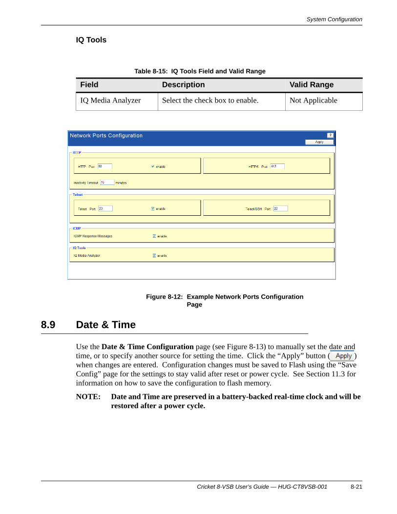
System Configuration
IQ Tools
Figure 8-12: Example Network Ports Configuration Page
8.9 Date & Time
Use the Date & Time Configuration page (see Figure 8-13) to manually set the date and time, or to specify another source for setting the time. Click the “Apply” button ( ) when changes are entered. Configuration changes must be saved to Flash using the “Save Config” page for the settings to stay valid after reset or power cycle. See Section 11.3 for information on how to save the configuration to flash memory.
NOTE: Date and Time are preserved in a battery-backed real-time clock and will be restored after a power cycle.
Table 8-15: IQ Tools Field and Valid Range
Field Description Valid Range
IQ Media Analyzer Select the check box to enable. Not Applicable
Cricket 8-VSB User’s Guide — HUG-CT8VSB-001 8-21

System ConfigurationSystem Configuration
Current
Time Source
Table 8-16: Current Field and Range
Field Description Valid Range
Current Time source Actual time source. May be different than the configured time source, such as if the connection to the SNTP server fails.
Read only
Table 8-17: Time Source Fields and Ranges
Field Description Valid Range
Time Source Source of date and time information.
SNTP Server, Manual/RTC Time, iVMS Server
SNTP Server IP Address Layer 3 address of the SNTP server
Available when Time Source is set to SNTP
Valid IP address
SNTP Update Period Duration between time updates in minutes
Available when Time Source is set to SNTP
1 – 60
Manual Time Configuration
Set the month, year, hours, minutes and seconds.
Available when Time Source is set to Manual/RTC Time.
Not Applicable
8-22 Cricket 8-VSB User’s Guide — HUG-CT8VSB-001

System Configuration
Adjustments
Figure 8-13: Example Date & Time Configuration Page
Table 8-18: Adjustments Fields and Ranges
Field Description Valid Range
Time Zone Universal time zone of the location of the system
Not Applicable
Auto Adjust Clock for Daylight Savings (DST) Changes
Select if the location is subject to DST
Not Applicable
Daylight Savings Time Change Offset
Number of minutes to add to the time during summer
0 – 240
Start of Summer Date and time DST starts Not Applicable
End of Summer Date and time DST ends Not Applicable
Cricket 8-VSB User’s Guide — HUG-CT8VSB-001 8-23

System ConfigurationSystem Configuration
8.10 RVL Config
Use the RVL Configuration page to set values specific to port 2. (See Figure 8-14.) The following values are configurable for the source and the destination modifier. When you have entered settings, press the “Update RVL Port” button ( ). RVL data is always streamed on the primary port.
NOTE: If RVL is active in manual mode and the configuration is saved, after a reset or power-on, the probe will attempt to automatically restart RVL. In order to prevent this condition, a save configuration should be performed with RVL stopped. See Section 11.3 for information on how to save the configuration to flash memory.
Table 8-19: RVL Configuration Field and Range
Field Description Valid Rangea
RVL AUTO Media data is encapsulated with the host/target Ethernet/IP packet parameters and the specified UDP port.
Source – Ethernet/IP source parameters are set to the probe's (target) management port settings
Destination – Ethernet/IP destination parameters are set to the host's network settings
Not Applicable
UDP Port Number Layer 4 port number for RVL Auto mode
1 – 65,535
RVL MANUAL MODE Media data is encapsulated with the specified Ethernet/IP/UDP packet parameters.
Not Applicable
Source/Destination MAC Address
Layer 2 address to insert the source/destination address
Valid MAC address
Source/Destination IP Address
Layer 3 address toinsert the source/destination address
Valid IP address
8-24 Cricket 8-VSB User’s Guide — HUG-CT8VSB-001

System Configuration
Manual Control: Use the “Start RVL” and “Stop RVL” buttons ( ) to start and stop modification of the packet before forwarding.
Figure 8-14: Example RVL Configuration Page
8.11 Remote Control Config
Use the Remote Control Configuration page to configure the Cricket to respond to a programmable remote control. (See Figure 8-15.) Four function codes are provided to work with a wide range of remotes. The Radio Shack 5-in-1 Family Favorites remote control has been verified to work with the Cricket. Other remotes and corresponding codes are show in Figure 8-20.
Source/Destination Port Layer 4 port to insert the source/destination port
0 – 65,535
a. Numbers in ranges greater than 999 contain commas for readability. Do not type the commas whentyping a number into a field.
Table 8-19: RVL Configuration Field and Range (Continued)
Field Description Valid Rangea
Cricket 8-VSB User’s Guide — HUG-CT8VSB-001 8-25

System ConfigurationSystem Configuration
To configure the Cricket, select Enable and the appropriate function setup code. Click the “Apply” button ( ) when changes are complete. Changes are lost after reset or a power cycle. See Section 10.1 for information on how to save the configuration to flash memory.
Refer to the remote user manual for instructions on programming the remote.
A universal remote control not in the table may work with the Cricket. Trial and error testing can determine if a specific remote will work. Here are the steps to follow:
1. Configure the Cricket for an AUX function setup code.
2. Save the configuration and reset the Cricket.
3. Configure the remote control to the same function setup code.
4. Point the remote directly at the front of the Cricket and press the “Enter” button or a numeric button on the remote. The census LED on the Cricket will flash red if the Cricket detects the press.
Note that not all buttons on the remote will cause the Cricket to respond. Typically the “Enter” button, “OK” button, and numeric buttons will work. If the Cricket does not respond to a button, try another button. If it does not respond to any buttons, try the process with a different function setup code.
Table 8-20: Remote Codes
Code Remote
3001 Admiral VCR, Montgomery Ward VCR, Motorola VCR, Radio Shack VCR, Realistic VCR, Sanky VCR, Sharp VCR, Signature VCR
3007 Bell & Howell VCR, Emerson VCR, Fisher VCR, Headquarter VCR, JVC VCR, Kenwood VCR, Marantz, Memorex VCR, NEC VCR, Quarter VCR, Quartz VCR, Radio Shack/Realistic VCR, Realistic VCR, Sanyo VCR, Sears VCR, Tandy VCR
3014 Candle VCR, Citizen VCR, Curtis Mathes VCR, Goldstar VCR, JVC VCR, Kenwood VCR, Marantz VCR, Memorex VCR, NEC VCR, Pentex Research VCR, Zenith VCR
3021 Adventura VCR, Aiwa VCR, Dynatech VCR, Emerson VCR, Gradiente VCR, Harley Davidson VCR, Lloyd's VCR, Memorex VCR, Radio Shack/Realistic VCR, Symphonic VCR, Wards VCR, XR-1000 VCR
8-26 Cricket 8-VSB User’s Guide — HUG-CT8VSB-001

System Configuration
Figure 8-15: Example Remote Control Configuration Page
Table 8-21: Remote Control Mode
Field Description Valid Range
Enable Enable remote control mode Not Applicable
Disable Disable remote control mode Not Applicable
Table 8-22: AUX Function Setup Code
Field Description Valid Range
3001 or 3007 or 3014 or 3021
Select a setup code to be used for remote control AUX function. The remote control must be configured for AUX function with the same setup code and channel selection for independent mode. See the remote control manual for more information.
Not Applicable
Cricket 8-VSB User’s Guide — HUG-CT8VSB-001 8-27

System ConfigurationSystem Configuration
8-28 Cricket 8-VSB User’s Guide — HUG-CT8VSB-001

Monitor Configuration
9 Monitor Configuration
Use the Monitor Configuration pages to configure global parameters and alarms and remote control. Global parameters are IQMediaAnalyzer-mode specific and affect overall IP flow acquisition. Global alarms parameters affect the unit level alarms.
9.1 Global Alarms
Use the Global Alarm Configuration page (see Figure 9-1) to activate and define thresholds of global alarms. Global alarms are System and Stream alarms that are not configurable by templates. These alarms apply to all identified network traffic. Click the “Apply” button ( ) after changes are made. Changes are lost after a reset or power cycle. See Section 11.3 for information on how to save the configuration to flash memory.
Cricket 8-VSB User’s Guide — HUG-CT8VSB-001 9-1

Monitor ConfigurationMonitor Configuration
General
Alarms
Table 9-1: General Field and Range
Field Description Valid Range
Alarm Generation Rate to Remote Hosts
Display the alarm when the traffic exceeds the specified percentage of available bandwidth.
Alarm Generation Rate defines Rate at which system generates SYSLOG and SNMP Traps to Remote Network Management Stations.
1 – 150
Continuous Alarm Clear Period to Clear a SET Alarm
Clear an alarm (red to yellow) after this duration of alarm-free seconds.
Continuous Alarm Clear Period is how long an alarm condition(s) must be in clear condition to clear the alarm.
1 – 120
Message Types to be Logged in the Alarm Log
Specify the message types to logged in the Alarm Log
All Messages, Alarms Only
Table 9-2: Alarms Field and Range
Field Description Valid Range
System Alarm Type
LINK-LOS: Link Status Select to display link loss LOS alarms when link loss is detected on the management ports
Not Applicable
SYS-MCHG: System Mode Change
This will change modes from monitoring mode to analysis mode when an IP Flow is being analyzed (recorded).
Not Applicable
9-2 Cricket 8-VSB User’s Guide — HUG-CT8VSB-001

Monitor Configuration
Figure 9-1: Example Global Alarm Configuration Page
LNK-MCHG: System Monitor Ports Tx/Rx Mode change
Select to send a message when the fronts ports link speed changes
Not Applicable
SYS_IVM: User Media Quality Feedback Notification
Indication that the Cricket “Viewer Feedback” front panel push button has been pressed.
Not Applicable
Video Alarm Type
VIDO-NEW: New Video Stream Detection
Select to trigger an alarm when a new video stream is detected
Not Applicable
VIDO-LOS: Video Stream Outage
Select to trigger an alarm when a previously detected video stream is no longer detected
Not Applicable
Stream Utilization Alarms
RVL Port 1 Stream Utilization Threshold
Display the alarm when the traffic exceeds the specified percentage of available bandwidth
1 – 100
Table 9-2: Alarms Field and Range (Continued)
Field Description Valid Range
Cricket 8-VSB User’s Guide — HUG-CT8VSB-001 9-3

Monitor ConfigurationMonitor Configuration
9.2 Global Parameters
Use the Global Parameters page to configure Cricket global settings. (See Figure 9-2.) Click the “Apply” button ( ) after changes are made. Changes are lost after a reset or power cycle. See Section 11.3 for information on how to save the configuration to flash memory.
Flow Census
Table 9-3: Flow Census Fields and Ranges
Field Description Valid Rangea
Recognition Mode Mode used for detecting flows
Alias: Only flows with an alias defined are displayed in the census
Media: Only flows detected as a valid media type are displayed in the census
Alias & Media: Only flows that meet both the Alias and Media criteria are displayed the census.
All: All detected flows are displayed in the census
Alias, Media, All, Alias & Media
Recognition Packet Threshold
Number of received packets to trigger recognition of a flow
Recognition Packet Threshold sets the minimum number of packets in a flow that must be detected in a limited amount of time for the flow to be placed into the census. This value is used only when Recognition Mode is set to “All”.
1 – 65,535
9-4 Cricket 8-VSB User’s Guide — HUG-CT8VSB-001

Monitor Configuration
Transport Streams
Enable Census During Capture/Record
Select to support flow census while doing capture
“Enable Census During Capture/Record” allows the user to specify whether census is enabled or disabled during any capture or record functions. If census is enabled, then the capture/record buffer may be less than the full 80 Mbytes due to census memory requirements.
Not Applicable
a. Numbers in ranges greater than 999 contain commas for readability. Do not type the commas whentyping a number into a field.
Table 9-4: Transport Streams Fields and Ranges
Field Description Valid Range
VLNK Descriptor Indicates Select the function of the VLNK descriptor
“VLNK Descriptor Indicates” determines how flows which contain one or more VLNK descriptors are handled. “Normal Flow” ignores the descriptor. “Menu Mode” causes these flows to be considered menu flows.
Normal Flow, Menu Flow
Allow Flows w/Missing PMT(s)
Select to allow detection of flows that do not have a PMT
“Allow Flows w/missing PMT(s)” allows flows with one or more absent PMTs to be added to the census.
Not Applicable
Table 9-3: Flow Census Fields and Ranges (Continued)
Field Description Valid Rangea
Cricket 8-VSB User’s Guide — HUG-CT8VSB-001 9-5

Monitor ConfigurationMonitor Configuration
Figure 9-2: Example Global Parameters Configuration Page
9.3 Capture
Use the Capture page to configure capture settings. (See Figure 9-3).
• init/exit – initializes/exits capture function
– initialize must be run once prior to starting capture
– exit should be run when capture function is no longer in use to release system resources
• start/stop – starts/stops capture run
– captured data is not available for upload until capture is stopped
• trigger – manually triggers capture
• “Auto Upload” parameters must be set when the initialize is run
Allow Flows w/Missing PAT Select to allow detection of flows that do not have a PAT
“Allow Flows w/missing PAT” allows flows without a PAT to be added to the census.
Not Applicable
Table 9-4: Transport Streams Fields and Ranges (Continued)
Field Description Valid Range
9-6 Cricket 8-VSB User’s Guide — HUG-CT8VSB-001

Monitor Configuration
The media loss trigger will fire if the MPEG transport stream packets (MTSP) loss exceeds the specified value within the specified period of time in seconds. The maximum time period is 60 seconds. The capture auto upload server IP address and port number are set from the System Managment Config page. Program/PID filtering is available for QAM port captures only. With program/PID filter captures, the capture overhead is higher relative to full flow capture since media data is stored on an individual MTSP basis rather than groups of MTSPs in flow capture, the additional overhead results in the actual amount of media data captured to be less than what is captured in flow mode. Program and PID filtering are mutually exclusive. If restart on RF channel change is enabled, then the active capture will be stopped and restarted, discarding all data contained in the capture buffer.
NOTE: The capture buffer may be less than 80 Mbytes if census is enabled during capture, to obtain the full 80 Mbytes, then census should be disabled during capture from the Global Parameters page.
If auto restart is selected, then the capture/upload will automatically begin after a reset or power cycle.
Click the “Apply” button ( ) after changes are made. A save configuration must be perfromed from the Save Config page to ensure trigger, filter, and port selections persist over a reset or power cycle. See Section 11.3 for information on how to save the configuration to flash memory.
NOTE: Program and PID filter selections do not persist over a reset or power cycle, even if the configuration is saved.
Triggers
Table 9-5: Triggers Fields and Ranges
Field Description Valid Rangea
Flow/Payload Alarm
Trigger on any flow or payload alarm enabled in the alarm templates.
Not Applicable
User Feedback Trigger on a push of the “Viewer Feedback” button on the front panel.
Not Applicable
Reed-Solomon Corrected
Trigger when a corrected Reed-Solomon error is detected.
This setting provides an early warning of potential Reed-Solomon uncorrected errors.
Not Applicable
Cricket 8-VSB User’s Guide — HUG-CT8VSB-001 9-7

Monitor ConfigurationMonitor Configuration
Filters
Program and PID filtering is available for QAM port captures only. With program and PID filter captures, the capture overhead is higher relative to full flow capture since media data is stored on an individual MTSP basis rather than groups of MTSPs in flow capture. The additional overhead results in the actual amount of media data captured to be less than what is captured in flow mode. Program and PID filtering are mutually exclusive.
Reed-Solomon Uncorrected
Trigger when an uncorrected Reed-Solomon error is detected
Not Applicable
Media Loss Trigger on media loss exceeding the specified number of MPEG transport stream packets (MTSP) over the specific time. Media loss trigger will fire if the MTSP loss exceeds the specified value within the specified period of time in seconds, the maximum time period is 60 seconds.
MTSP range 1 – 4,294,967,295
Seconds range 1 – 60
MTSP Trigger on media loss exceeding the specified number of MTSP over the specific time.
MTSP range 1 – 4,294,967,295
Seconds range 1 – 4,294,967,295
Errored Seconds
Trigger on the specified number of errored seconds.
1 – 4,294,967,295
Position Set the trigger position within the capture buffer.
0 – 100%
a. Numbers in ranges greater than 999 contain commas for readability. Do not type the commas whentyping a number into a field.
Table 9-6: Port Filters Fields and Ranges
Field Description Valid Range
QAM Only Select “QAM Only” to capture traffic on the RF port.
Not Applicable
Restart on RF channel change
Select to restart the capture when the channel changes in Scan mode.
Not Applicable
Table 9-5: Triggers Fields and Ranges (Continued)
Field Description Valid Rangea
9-8 Cricket 8-VSB User’s Guide — HUG-CT8VSB-001

Monitor Configuration
Status
The Status box shows the status of the capture, either Uninitialized or Ready.
Ethernet Only Select Ethernet only to capture traffic on the Ethernet input port only.
Not Applicable
Table 9-7: Program Filters Fields and Ranges
Field Description Valid Range
Enable Enables capture of a selected program only
Not Applicable
Program The program to capture MPEG programs as detected for flow
Update Apply program selection Not Applicable
Table 9-8: PID Filters Fields and Ranges
Field Description Valid Range
Enable Enables capture of a selected PID only Not Applicable
PID PID to capture MPEG PIDs as detected for flow
Update Apply PID selection Not Applicable
Table 9-9: Status Fields and Ranges
Field Description Valid Range
Uninitialized This box indicates the current capture status.
Not Applicable
Ready This box indicates the current capture status.
Not Applicable
Table 9-6: Port Filters Fields and Ranges (Continued)
Field Description Valid Range
Cricket 8-VSB User’s Guide — HUG-CT8VSB-001 9-9

Monitor ConfigurationMonitor Configuration
Control
The Control box displays a button to control the capture. The function varies based on the capture state, either Init, Start or Exit.
Table 9-10: Control Fields and Ranges
Field Description Valid Range
Init Initializes capture function
Auto Upload parameters must be set when the initialize is run. Initialize must be run once prior to starting a capture.
Not Applicable
Start Starts a capture run Not Applicable
Stop Stops a capture run
Captured data is not available for upload until the capture is stopped.
Not Aplicable
Exit Exits capture function
Exit should be run when capture function is no longer in use to release system resources.
Not Applicable
9-10 Cricket 8-VSB User’s Guide — HUG-CT8VSB-001

Monitor Configuration
Upload
Auto Upload
The capture auto upload server IP address and port number are set from the System Management Config page (see Section 8.6). This is only used if you are performing auto upload from iVMS.
Table 9-11: Upload Field and Range
Field Description Valid Range
Data available or No data available
This box shows the amount of data and packets available for upload after a capture has been performed. “No data available” indicates that there has been no data available in the capture for upload. When data is available, an arrow icon appears that can be clicked to upload the data.
Not Applicable
Table 9-12: Auto Upload Fields and Ranges
Field Description Valid Rangea
Count The maximum number of trigger/capture cycles to perform after a reset/power-on if Auto Restart mode is enabled.
1 – 65,535
Buffer Size The maximum trigger/capture buffer size when Auto Restart mode is enabled. This field is also used to configure the default buffer size when trigger/capture is controlled from the iVMS.
1 Mbyte-80 Mbyte (Note that Census must be disabled from the Global Parameters page [see Section 9.2] in order to allocate the full 80 Mbytes of buffer).
Cricket 8-VSB User’s Guide — HUG-CT8VSB-001 9-11

Monitor ConfigurationMonitor Configuration
Figure 9-3: Example Capture Configuration Page
Auto Restart Used to configure the Cricket to automatically re-arm trigger/capture after a reset/power-on. (Note that use of this feature is not supported and may be deprecated in future releases).
Not Applicable
a. Numbers in ranges greater than 999 contain commas for readability. Do not type the commas whentyping a number into a field.
Table 9-12: Auto Upload Fields and Ranges (Continued)
Field Description Valid Rangea
9-12 Cricket 8-VSB User’s Guide — HUG-CT8VSB-001
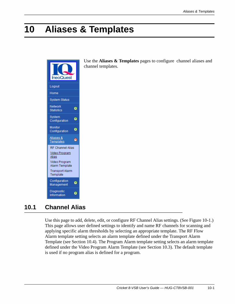
Aliases & Templates
10 Aliases & Templates
Use the Aliases & Templates pages to configure channel aliases and channel templates.
10.1 Channel Alias
Use this page to add, delete, edit, or configure RF Channel Alias settings. (See Figure 10-1.) This page allows user defined settings to identify and name RF channels for scanning and applying specific alarm thresholds by selecting an appropriate template. The RF Flow Alarm template setting selects an alarm template defined under the Transport Alarm Template (see Section 10.4). The Program Alarm template setting selects an alarm template defined under the Video Program Alarm Template (see Section 10.3). The default template is used if no program alias is defined for a program.
Cricket 8-VSB User’s Guide — HUG-CT8VSB-001 10-1

Aliases & TemplatesAliases & Templates
You can also download an alias file to the probe from iVMS or the Web page of the probe. If you perform a “learn” ( ) from the RF Tuner Config Web Page (see Section 8.1), it will scan the frequency map and create aliases of the RF and program combinations it finds.
The numbers associated with each field name indicate the column number in the alias file download and upload and must be in parentheses for new file download. The maximum limit of unique Flow Aliases for the system is 256.
Click the “Add/Update” button ( ) after changes are made. Changes are lost after a reset or power cycle. See Section 11.3 for information on how to save the configuration to flash memory.
RF Flow Alias Template
Characteristics
Table 10-1: RF Flow Alias Template Fields and Ranges
Field Description Valid Range
Template List of existing templates
Not Applicable
Alias Name User-specified template name
1 – 32 byte string
(See Appendix A for a list of supported characters.)
Table 10-2: Characteristics Fields and Ranges
Field Description Valid Range
RF Channel The RF channel Valid channel
RF Flow Alarm Template
The RF Flow Alarm Template selection
Not Applicable
Program Alarm Template
The Program Alarm Template selection
Not Applicable
Video Program Alias(es)
The Video Program Alias(es) selection Not Applicable
10-2 Cricket 8-VSB User’s Guide — HUG-CT8VSB-001

Aliases & Templates
The “Delete All” button ( ) will delete all Channel Aliases. The “Delete” button ( ) will delete selected the Channel Alias.
Figure 10-1: Example RF Channel Alias Page
10.2 Video Program Alias
Use the Video Program Alias Names page to assign names to video programs. See Figure 10-2 for an example page. If PID Monitoring is enabled without specifying Bitrate thresholds, then PID Bitrate thresholds specified in the Media Payload Alarm Template will take effect.
The numbers by each field name indicate the column number in an Alias file. These numbers in upload file header and must be in parentheses for new file download.
Click the “Add/Update” button ( ) after changes are made. Changes are lost after a reset or power cycle. See Section 11.3 for information on how to save the configuration to flash memory.
Cricket 8-VSB User’s Guide — HUG-CT8VSB-001 10-3
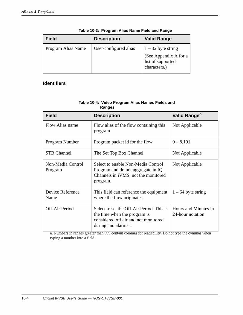
Aliases & TemplatesAliases & Templates
Identifiers
Table 10-3: Program Alias Name Field and Range
Field Description Valid Range
Program Alias Name User-configured alias 1 – 32 byte string
(See Appendix A for a list of supported characters.)
Table 10-4: Video Program Alias Names Fields and Ranges
Field Description Valid Rangea
a. Numbers in ranges greater than 999 contain commas for readability. Do not type the commas whentyping a number into a field.
Flow Alias name Flow alias of the flow containing this program
Not Applicable
Program Number Program packet id for the flow 0 – 8,191
STB Channel The Set Top Box Channel Not Applicable
Non-Media Control Program
Select to enable Non-Media Control Program and do not aggregate in IQ Channels in iVMS, not the monitored program.
Not Applicable
Device Reference Name
This field can reference the equipment where the flow originates.
1 – 64 byte string
Off-Air Period Select to set the Off-Air Period. This is the time when the program is considered off air and not monitored during “no alarms”.
Hours and Minutes in 24-hour notation
10-4 Cricket 8-VSB User’s Guide — HUG-CT8VSB-001

Aliases & Templates
Program Monitoring Template
Figure 10-2: Example Video Program Alias Names Page
10.3 Video/Program Alarm Template
Table 10-5: Program Monitoring Template Fields and Ranges
Field Description Valid Range
Program Template The Program Monitoring Template selection to be used during the on-air period.
Not Applicable
Program Off-Air Template
The Program Off-Air Template is the template to be used during the off-air period.
Not Applicable
Cricket 8-VSB User’s Guide — HUG-CT8VSB-001 10-5

Aliases & TemplatesAliases & Templates
IneoQuest uses the Media Delivery Index (MDI) standard proposed in RFC4445 to indicate Media Loss Rate (MLR). MLR is calculated by tracking the Continuity Counter numbers associated with each PID in the MPEG Transport Stream and reporting loss at the Program Level. Under the “Video/Program Channel Alarm Template”, the maximum allowed values may be set. These are thresholds that when exceeded will trigger an alarm.
IneoQuest uses MLR (per second) to trigger an Media Loss Seconds-Loss Period (MLS-LP) alarm. MLS-LP is the number of consecutive MLR seconds exceeding the MLR threshold. Media Loss Seconds-Loss Distance (MLS-LD) is the distance between two MLS-LP events.
For initial troubleshooting at the headend, it is recommended that all fields in the “Video/Program Alarm Template” are selected with the default threshold values. To enable these fields, select the checkbox next to the field and type in in the appropriate threshold.
Changes are applied with “Add/Update” and “Delete” buttons but must be saved to FLASH using the “Save Config” page for the settings to stay valid after reset or power cycle. Program Template entry thresholds are applied to all programs of a single Flow or multiple IP Flow(s) from the “Video/IP Flow Alias Name” page. Program Template Thresholds can also be applied “Video Program Alias” Page. The Program Template applied from the “Video Program Alias” page supercedes the Flow Alias Program Template.
All the values entered in this page including PID Numbers and PID Type(s) must be in decimal. “User Specified PID Rules” take precedence. CC Loss and Bitrate computation will be disabled if any PIDs or PID Types are “Ignored”. The “PID Outage Trigger Period” and the “PID Bitrate Trigger Period” indicates the number of consecutive seconds the alarm condition should persist before generating the alarm.
A zero for any threshold for an enabled alarm causes the system to use a default value for the corresponding threshold. When a Program Template entry is deleted the thresholds for the corresponding Programs will be reset to the “ProgramDefault” Template values.
The Transport Video Stream “Off-Air Period” is based on Target System Time expressed in “Hours:Minutes” based on a 24 Hour Clock (for example: 23:30 to 04:00).
Click the “Add/Update” button ( ) after changes are made. Changes are lost after a reset or power cycle. See Section 11.3 for information on how to save the configuration to flash memory.
See Figure 10-3 for an example of the Video/Program Alarm Template.
Video/Program Alarm Template
Table 10-6: Video/Program Alarm Template Fields and Ranges
Field Description Valid Range
Template List of existing templates Not Applicable
10-6 Cricket 8-VSB User’s Guide — HUG-CT8VSB-001

Aliases & Templates
Program Media Loss (CC) Alarms
Template Name User-specified template name 1 – 32 byte string
(See Appendix A for a list of supported characters.)
Table 10-7: Program Media Loss (CC) Alarms Fields and Ranges
Field Description Valid Rangea
MDI-MLR: Media Loss Min value to count MLS (Media Pkts/sec)
The threshold to trigger an MLS-LP alarm
1 – 512
MLS-LP: Number of Contiguous Loss Seconds
Select to enable the alarm and set the value of the number of contiguous seconds of loss exceeding the MDI-MLR threshold.
1 – 65,535
MLS-LD: Min. Distance between MLS-LP events (secs)
Select to enable the alarm and set the value for the minimum distance between loss seconds. You need at least two MLS-LP events before you can get this.
1 – 65,535
MLT-15: Total Media Loss in 15-Min. Max. Value
Generate the alarm if the total media transport stream packets lost in the current 15 minutes exceeds a value you specify in packets
1 – 1,147,483,647
MLT-24: Total Media Loss in 24-Hr Max value
Generate the alarm if the total media transport stream packets lost in the current 24 hours exceeds a value you specify in packets
1 – 1,147,483,647
Table 10-6: Video/Program Alarm Template Fields and Ranges (Continued)
Field Description Valid Range
Cricket 8-VSB User’s Guide — HUG-CT8VSB-001 10-7

Aliases & TemplatesAliases & Templates
Program Monitoring Alarms
MLS-24: Total Loss Seconds in 24-Hr Max Value (secs)
Generate the alarm if the total number of seconds experiencing media transport stream packet loss in the current 24 hours exceeds a value you specify in seconds. This clears at midnight and is not a rolling 24 hours.
1– 3,600
MLS-15: Loss Seconds in 15-Min. Max Value (secs)
Generate the alarm if the total number of seconds experiencing media transport stream packet loss in the current 15 minutes exceeds a value you specify in seconds
1 – 900
a. Numbers in ranges greater than 999 contain commas for readability. Do not type the commas whentyping a number into a field.
Table 10-8: Program Monitoring Alarms Fields and Ranges
Field Description Valid Rangea
Program Scrambling State mismatch Trap
Generate an alarm if one program scrambled state does not match what is set
“Should Not be Scrambled” or “Should be Scrambled”
PID Outage Trigger Period (secs)
The number of continous seconds of a condition to generate an alarm
1 – 128
Ad-Insertion PID(SCTE-35) event detection
Generate an alarm for ad-insertion packet identifier detection when a bitrate occurs on the SCTE-35 PID. The alarm clears when it goes away.
“Monitor SCTE Type” or “Monitor User PID”
(Set Type in field below)
Dial Norm Change Trap for Audio AC-3 PID(s)
Generate a trap if the Dialogue Normalization valuechanges for Audio AC-3 PID(s)
Not Applicable
Table 10-7: Program Media Loss (CC) Alarms Fields and Ranges (Continued)
Field Description Valid Rangea
10-8 Cricket 8-VSB User’s Guide — HUG-CT8VSB-001

Aliases & Templates
User PID Monitoring Rules
Program Control PID(s) Monitoring Status
Set the status type for Program Control PID(s) Monitoring. This is for control PIDs only, such as SCTE-35, ECM, etc.
“Monitor Loss Only”, “Monitor Loss & Outage”, or “Ignore All PIDs”
PID Bitrate Trigger Period (secs)
The number of continous seconds of a condition to generate an alarm
1 – 255
Ignore Secondary Audio PIDs
Select to ignore the secondary audio packet identifiers. The first audio PID listed in the Program Map Table (PMT) is considered the primary audio PID. All others will be ignored for bitrate and outage.
Not Applicable
a. Numbers in ranges greater than 999 contain commas for readability. Do not type the commas whentyping a number into a field
Table 10-9: Video/Program Alarm Template Fields and Ranges
Field Description Valid Range
User Specified PID Rules
Set the User Specified PID Rules for up to three PIDs including the “Value” or a range by setting the “Min. Value” and “Max. Value”
You can set bitrate alarms on these PIDs and force detection.
“Monitor By Number”, “Monitor By Type”, “Monitor From List”, “Ignore By Number”, “Ignore By Type”, or “Ignore from List”
Table 10-8: Program Monitoring Alarms Fields and Ranges (Continued)
Field Description Valid Rangea
Cricket 8-VSB User’s Guide — HUG-CT8VSB-001 10-9

Aliases & TemplatesAliases & Templates
Program PID Bitrate Monitoring Alarms
Table 10-10: Program PID Bitrate Monitoring Alarms Fields and Ranges
Field Description Valid Rangea
a. Numbers in ranges greater than 999 contain commas for readability. Do not type the commas whentyping a number into a field
Video PID Bit Rate Threshold
Set for an “Outage” and/or a minimum and/or maximum value bitrate. Use this setting to generate an alarm.
1 – 1,147,483,647
Audio PID Bit Rate Threshold
Set for an “Outage” and/or a minimum and/or maximum value to generate an alarm. Use the PID Outage and PID Bitrate trigger period alarms with this.
1 – 1,147,483,647
PMT PID Outage Enable to monitor PMT for outage Not Applicable
PCR PID Outage Enable to monitor PCR PID for outage Not Applicable
10-10 Cricket 8-VSB User’s Guide — HUG-CT8VSB-001

Aliases & Templates
Figure 10-3: Example Video/Program Alarm Template Page
10.4 Video Transport Alarm Template
Use the Video Program Alias Names page to assign names to video programs. (See Figure 10-4.)
IneoQuest not only tracks health at the program level but the transport level as well. The same MDI standard proposed in RFC4445 to indicate Media Loss Rate (MLR) is used. Under the Video Transport Alarm Template, maximum allowed values may be set. Thresholds here pertain to elements of the Transport Stream and not the Programs as well as TR 101 290 level 1 and 2 thresholds. These are thresholds that, when exceeded, will trigger an alarm.
For initial troubleshooting at the headend, it is recommended that all fields in the Video Transport Alarm Template be selected with the default threshold values. To enable these fields, check the checkbox next to the field and enter in the appropriate threshold.
Click the “Add/Update” button ( ) after changes are made. Changes are lost after a reset or power cycle. See Section 11.3 for information on how to save the configuration to flash memory.
Cricket 8-VSB User’s Guide — HUG-CT8VSB-001 10-11

Aliases & TemplatesAliases & Templates
Video Transport Alarm Template
Table 10-11: Video Transport Alarm Template Fields and Ranges
Field Description Valid Range
Template List of existing templates Not Applicable
Template Name User-specified template name 1 – 32 byte string
(See Appendix A for a list of supported characters.)
Table 10-12: Video Transport Flow Alarm Template Fields and Ranges
Field Description Valid Rangea
TUN-SNR: RF Signal to Noise ratio below threshold (dB)
Select to set the value for the minimum SNR threshold
0 – 60
RS-UC: Uncorrected Errors Rate Max value (Errors/sec)
Select to generate an alarm if the specified threshold is exceeded
0 – 65,535
RS-UC15: Uncorrected Errors 15-Min. Max. value
Select to set the value for maximum uncorrected errors in a 15-minute period
0 – 65,535
RS-CO15: Corrected Errors 15-Min. Max. value
Select to set the value for maximum corrected errors in a 15-minute period
0 – 65,535
VIDO-LOS: Enable RF Channel Outage Alarm
Select to enable an alarm when there is an RF channel outage (no packets received on flow for one second)
1 – 120
TUN-SIG: Tuner RF Signal Loss
Select to generate an alarm when there is a tuner RF signal loss
Not Applicable
10-12 Cricket 8-VSB User’s Guide — HUG-CT8VSB-001

Aliases & Templates
Figure 10-4: Example Video/Program Transport Flow Alarm Template Page
10.4.1 Transport Stream
See Figure 10-5 for an example of the Transport Stream page of the Video Transport Alarm Template.
RS-CO: Corrected Errors Rate Max. value (Errors/sec)
Select to generate an alarm based on the threshold set
0 – 65,535
RS-UC24: Uncorrected Errors 24-Hr. Max. Value
Select to generate an alarm based on the threshold set
0 – 2,147,483,647
RS-CO24: Corrected Errors 24-HR. Max. Value
Select to set the value for maximum corrected errors in a 24-hour period
0 – 2,147,483,647
a. Numbers in ranges greater than 999 contain commas for readability. Do not type the commas whentyping a number into a field.
Table 10-12: Video Transport Flow Alarm Template Fields and Ranges (Continued)
Field Description Valid Rangea
Cricket 8-VSB User’s Guide — HUG-CT8VSB-001 10-13

Aliases & TemplatesAliases & Templates
Table 10-13: Video Transport Stream Alarm Template Fields and Ranges
Field Description Valid Rangea
General
TS Video Service Name Detection
Set the value for the Transport Stream Video Service Name Detection
You can use IQMediaAnalyzer Pro™ to create aliases for flows and programs with names detected.
Disable, May Be Present, Must Be Present
(Flows will not be discovered if this does not match.)
Stream End Timeout (secs)
Set the value for Stream End Timeout in seconds after the flow is not on the census for VOD flows
1 – 300
Bit Rate Type Set the display of the Bit Rate Type
Use to declare a flow as variable or constant. This is used to determine the algorithm for MDI-DF calculations. Generally flows with a stuffing PID or stuffing within a video PID are variable bit rate (VBR). “Auto-Detect” assumes VBR first.
Auto-Detect, Constant, Variable
Stream Bit Rate Select and set the Stream Bit Rate
Stream Bit Rate is used to calculate MDI-DF. Only use this to force a bit rate when none would otherwise be detected based on PCR.
1 – 1,147,483,647
V-TSB: Video-TS PCR Bitrate deviation (%)
Select to generate an alarm based on a percent deviation in the value for the Video Transport Bit Rate
1 – 100
UNREF-PID: UnReferenced/Ghost PID
Select to alarm on detection of an UnReferenced/Ghost PID in the PAT Table (any PID not in PAT or PMT). PMTs not in PAT but in flow will be detected as PMT, but will not generate an UnReferenced PID.
Not Applicable
10-14 Cricket 8-VSB User’s Guide — HUG-CT8VSB-001

Aliases & Templates
PAT PID Outage Select to alarm if there is a Program Association Table PID outage
Not Applicable
Program Changes
Trap On Program Add/Remove From Census
Enableto generate a trap to iVMS if the probe detects a program or PID change based on a PAT or PMT revision
Not Applicable
Remove Program from Census if Removed from PAT
Select to remove a program from census if it is removed from the Program Association Table
Not Applicable
Leave Program in Census if Removed from PAT
Select to leave a program in census if it is removed from the Program Association Table
Not Applicable
Stuffing PID Threshold
Minimum (bps) Enable to generate an alarm if the Stuffing PID Bit Rate goes below the value entered for the PID contiguous alarm period (Global Alarm Parameter)
1 – 1147483647
Maximum (bps) Enable to generate an alarm if the Stuffing PID Bit Rate goes above the value entered for the PID contiguous alarm period (Global Alarm Parameter)
1 – 1147483647
Non-Program PID Monitoring
Monitoring Level Monitor PIDs for Loss only.
Monitor PIDS for Loss And Outage.
DO NOT MONITOR PIDS.
Loss Only, Loss & Outage, None
MDI-MLR: Media Loss Rate Max value (Media Pkts/sec)
The threshold to trigger an MLS-LP alarm
1 – 512
Table 10-13: Video Transport Stream Alarm Template Fields and Ranges (Continued)
Field Description Valid Rangea
Cricket 8-VSB User’s Guide — HUG-CT8VSB-001 10-15

Aliases & TemplatesAliases & Templates
MLS-LP: Number of Contiguous Loss Seconds
Select to enable the alarm and set the value of the number of contiguous seconds of loss exceeding the MDI-MLR threshold.
1 – 65,535
MLS-LD: Min. Distance between Loss Seconds
Select to enable the alarm and set the value for the minimum distance between loss seconds. You need at least two MLS-LP events before you can get this.
1 – 65,535
MLT-15: Total Media Loss in 15-Min. Max. value
Generate the alarm if the total media transport stream packets lost in the current 15 minutes exceeds a value you specify in packets
1 – 1,147,483,647
MLT-24: Total Media Loss in 24-Hr Max. value
Generate the alarm if the total media transport stream packets lost in the current 24 hours exceeds a value you specify in packets
1 – 1,147,483,647
MLS-15: Loss Seconds in 15-Min. Max. Value (secs)
Generate the alarm if the total number of seconds experiencing media transport stream packet loss in the current 15 minutes exceeds a value you specify in seconds
1 – 900
MLS-24: Total Loss Seconds in 24-Hr Max. Value (secs)
Generate the alarm if the total number of seconds experiencing media transport stream packet loss in the current 24 hours exceeds a value you specify in seconds. This clears at midnight and is not a rolling 24 hours.
1 – 3,600
Transport Stream User PIDs
Table 10-13: Video Transport Stream Alarm Template Fields and Ranges (Continued)
Field Description Valid Rangea
10-16 Cricket 8-VSB User’s Guide — HUG-CT8VSB-001

Aliases & Templates
User PID #1 through #4
Select to:
• “Monitor By Number” (the number is the PID number),
• “Monitor By Type” (the type is MPEG PID type, if applicable),
• “Monitor From List”(the list is for PIDs that do not have a PID type),
• “Ignore By Number”,
• “Ignore By Type”,
• “Ignore From List”
0 – 8,191
Mask Errors During FF/Rewind
Mask Errors During FF/Rewind
Select to enable masking bitrate, loss, or outage errors during fast forward or rewind and set either the value “for Seconds” or set the value “During Audio Blanking”.
If the discontinuity bit is set, this will mask bitrate, loss, outage.
Not Applicable
for Seconds Select to set the value in seconds after the fast forward or rewind bit goes away.
1 – 300
During Audio Blanking
Select to mask errors during fast forward or rewind during audio blanking and set the number of seconds after audio blanking stops.
1 – 300
a. Numbers in ranges greater than 999 contain commas for readability. Do not type the commas whentyping a number into a field.
Table 10-13: Video Transport Stream Alarm Template Fields and Ranges (Continued)
Field Description Valid Rangea
Cricket 8-VSB User’s Guide — HUG-CT8VSB-001 10-17

Aliases & TemplatesAliases & Templates
Figure 10-5: Example Video/Program Transport Stream Alarm Template Page
10.4.2 ETSI TR 101 290
Click the “ETSI TR 101 290” tab to enter settings to monitor flows for ETSI TR 101 290. See Figure 10-6 for an example of the “ETSI TR 101 290” page. The lowest (left-most) setting of each slider represents the ETSI TR 101 290 recommended interval. Priority 1 and 2 alarms are supported. Priority 3 alarms are not supported at this time.
Table 10-14: Video Transport ETSI TR 101 290 Alarm Template Fields and Ranges
Field Description Valid Rangea
First Priority
1.3 PAT Error Display an alarm if a PAT error is detected for a duration exceeding the specified duration in milliseconds
500 – 2,500
10-18 Cricket 8-VSB User’s Guide — HUG-CT8VSB-001

Aliases & Templates
1.4 Continuity Count Error
Display an alarm if a continuity count error is detected. This is analogous to media loss.
Not Applicable
1.5 PMT Error Display an alarm if a PMT error is detected for a duration exceeding the specified duration in milliseconds
500 – 2,500
1.6 PID Error Display an alarm if a PID error is detected for the specified PID for a duration exceeding the specified duration in milliseconds. PID numbers need to be entered in decimal.
PID: 0 – 8,191
Duration: 100 – 5,000
Second Priority
2.1 Transport Error Display an alarm if a transport error is detected
Not Applicable
2.2 CRC Error Display an alarm if a CRC error is detected
Not Applicable
2.3a PCR Repetition Error
Display an alarm if a PCR repetition error is detected for a duration exceeding the specified duration in milliseconds
40 – 1,000
2.3b PCR Discontinuity Error
Display an alarm if a PCR discontinuity error is detected for a duration exceeding the specified duration in milliseconds
100 – 2,500
2.4 PCR Accuracy Error
Display an alarm if a PCR accuracy error is detected for a duration exceeding the specified duration in nanoseconds
500 – 2,500
2.5 PTS Repetition Error
Display an alarm if a PTS repetition error is detected for a duration exceeding the specified duration in milliseconds
700 – 2,500
Table 10-14: Video Transport ETSI TR 101 290 Alarm Template Fields and Ranges (Continued)
Field Description Valid Rangea
Cricket 8-VSB User’s Guide — HUG-CT8VSB-001 10-19

Aliases & TemplatesAliases & Templates
Figure 10-6: Example Video Transport ETSI Alarm Template Page
2.6 CAT Error Display an alarm if a CAT error is detected
Not Applicable
a. Numbers in ranges greater than 999 contain commas for readability. Do not type the commas whentyping a number into a field.
Table 10-14: Video Transport ETSI TR 101 290 Alarm Template Fields and Ranges (Continued)
Field Description Valid Rangea
10-20 Cricket 8-VSB User’s Guide — HUG-CT8VSB-001

Configuration Management
11 Configuration Management
Use the Configuration Management pages to download new firmware releases into the unit, download and upload configuration files, save the running configuration to flash and reset the unit.
11.1 Download/Upload Configuration
Use the Download/Upload Configuration page to transfer configuration settings between the host and the Cricket 8-VSB. Selections allow the user to download a Configuration file from the host to the system and upload a Configuration File from the monitoring/analysis system to the host.
Configuration files include all configuration and alarm settings except for System IP Configuration and Port Configuration settings. The user must click the “Save Config & Reset System” button ( ) in order for all the downloaded changes to take effect.
Cricket 8-VSB User’s Guide — HUG-CT8VSB-001 11-1

Configuration ManagementConfiguration Management
All the Aliases can be uploaded to the host for editing the fields and then downloaded into the system. Refer to Figure 11-1 for a view of the Download/Upload Configuration page.
Figure 11-1: Example Download/Upload Configuration Page
11.1.1 Download Configuration: From Host to the Cricket 8-VSB
11.1.1.1 Send this file:
1. On the “Download Configuration” page, click the “Browse” button to locate the host file to download.
2. Identify the configuration file, alias text file, or SSL Certificate file on the host that will be downloaded to the Cricket 8-VSB (See Figure 11-2 for an example.).
11-2 Cricket 8-VSB User’s Guide — HUG-CT8VSB-001

Configuration Management
Figure 11-2: Locate the File on the Host
3. Click the file name and then click “Open”. The file name will appear in the “Send this file:” field on the “Download Configuration” Web page of the Cricket 8-VSB.
4. Click the appropriate button on the Cricket 8-VSB Web page to initiate the type of operation that you want to perform.
– SAVE CONFIG & RESET SYSTEM. ( ) Transfer a configuration file to the Cricket 8-VSB. The system will reset. Press F5 to refresh the browser after the reset.
– DOWNLOAD ALIAS. ( ) Transfer an alias file to the Cricket 8-VSB.
– DOWNLOAD CERTIFICATE. ( ) Secure Sockets Layer (SSL) Certificate File Download to the Cricket 8-VSB from the Host.
11.1.2 Upload Configuration to the Host from the Cricket 8-VSB
11.1.2.1 Upload System Config File
Transfer the system configuration file from the Cricket 8-VSB to the host. The system configuration file is a binary file and cannot be edited. The default file name is: IQConfig_system (probe) name.ini
1. Click the “Upload System Config File” button.
Cricket 8-VSB User’s Guide — HUG-CT8VSB-001 11-3

Configuration ManagementConfiguration Management
2. A “File Download” window similar to the one in Figure 11-3 will appear.
Figure 11-3: “File Download” Window
3. Click the “Save” button. Locate the area on the host where you want to save the configuration file (See Figure 11-4 for an example.).
11-4 Cricket 8-VSB User’s Guide — HUG-CT8VSB-001

Configuration Management
Figure 11-4: Host Location to Save Config File
4. Click the “Save” button.
5. Depending on your host’s settings, a “Download Complete” window similar to the one in Figure 11-5 will appear.
Cricket 8-VSB User’s Guide — HUG-CT8VSB-001 11-5

Configuration ManagementConfiguration Management
Figure 11-5: “Download Complete” Window
6. Click the “Close” button.
11.1.2.2 Upload AliasConfig Text File
Transfer the alias configuration file from the Cricket 8-VSB to the host.
1. Click the “Upload AliasConfig Text File” button. A “File Download” window similar to the one in Figure 11-6 will open.
Figure 11-6: Save the AliasConfig File
11-6 Cricket 8-VSB User’s Guide — HUG-CT8VSB-001

Configuration Management
2. Click the “Save” button.
3. A “Save As” window will open similar to the one in Figure 11-7. Locate the area on the host where you want to save the AliasConfig file.
Figure 11-7: Locate the Area to Save the AliasConfig File
4. Click the “Save” button.
5. Depending on your host’s settings, a “Download Complete” window similar to the one in Figure 11-8 will appear.
Cricket 8-VSB User’s Guide — HUG-CT8VSB-001 11-7

Configuration ManagementConfiguration Management
Figure 11-8: “Download Complete” Window
6. Click the “Close” button.
11.1.2.3 Upload Syslog File
Transfer the Syslog file from the Cricket 8-VSB to the host.
1. On the “Download Configuration” page, click the “Upload Syslog File”.
2. A “File Download” window similar to the one in Figure 11-9 will open.
Figure 11-9: Save the Syslog File
11-8 Cricket 8-VSB User’s Guide — HUG-CT8VSB-001

Configuration Management
3. Click the “Save” button and a “Save As” window will open similar to Figure 11-10.
Figure 11-10: “Save As” Window
4. Locate the area on the host where you want to save the Syslog file and click the “Save” key.
5. Depending on your host’s settings, a “Download Complete” window similar to the one in Figure 11-11 will appear.
Cricket 8-VSB User’s Guide — HUG-CT8VSB-001 11-9

Configuration ManagementConfiguration Management
Figure 11-11: “Download Complete” Window
6. Click the “Close” button.
11.1.2.4 Upload Syslog And Clear Log
Transfer the Syslog file from the Cricket 8-VSB to the host and then erase the entries in the Syslog on the Cricket 8-VSB.
1. On the “Download Configuration” page, click the “Upload Syslog And Clear LOG” button. A window similar to Figure 11-12 will open.
Figure 11-12: “File Download” Window
11-10 Cricket 8-VSB User’s Guide — HUG-CT8VSB-001

Configuration Management
2. Click the “Save” button and a “Save As” window similar to the one in Figure 11-13 will open.
Figure 11-13: “Save As” Window
3. Locate the area on the host where you want to save the file and click the “Save” button.
4. Depending on your host’s settings, a “Download Complete” window similar to the one in Figure 11-14 will appear.
Cricket 8-VSB User’s Guide — HUG-CT8VSB-001 11-11

Configuration ManagementConfiguration Management
Figure 11-14: “Download Complete” Window
5. Click the “Close” button.
11.1.2.5 Upload Flow Statistics
“Upload Flow Statistics” transfers the history of flows since the probe was last reset from the Cricket QAM Plus to the HOST. (For information on flow statistics, refer to Section 7.2.)
1. On the “Download Configuration” page, click the “Upload Flow Statistics” button, and a “File Download” window similar to the one in Figure 11-15 will appear.
11-12 Cricket 8-VSB User’s Guide — HUG-CT8VSB-001

Configuration Management
Figure 11-15: “File Download” Window
2. Click the “Save” and a “Save As” window similar to Figure 11-16 will open.
Figure 11-16: “Save As” Window
Cricket 8-VSB User’s Guide — HUG-CT8VSB-001 11-13

Configuration ManagementConfiguration Management
3. Locate the area on the host where you want to save the Flow History file.
4. Click the “Save” button.
5. Depending on your host’s settings, a “Download Complete” window similar to the one in Figure 11-17 will appear.
Figure 11-17: “Download Complete” Window
6. Click the “Close” button.
11.2 Download Firmware
Use the Download Firmware page to update the firmware on the Cricket 8-VSB. Selections allow you to download Firmware file (*.IQZ) from the host to the Monitoring/Analysis system. The Monitoring, Capture and Stimulus capabilities will be disabled after software download is initiated. You must Save the downloaded Firmware to activate the software. Refer to Figure 11-18 for a view of the “Firmware Download” page.
11-14 Cricket 8-VSB User’s Guide — HUG-CT8VSB-001

Configuration Management
Figure 11-18: “Firmware Download” Page
11.2.0.1 Download Firmware
7. Click the “Browse” button to locate the host file to download and a window similar to Figure 11-19 will open.
Cricket 8-VSB User’s Guide — HUG-CT8VSB-001 11-15

Configuration ManagementConfiguration Management
Figure 11-19: Locate the Firmware File to Download
8. Click the file name and then click “Open”. The file name will appear in the “Send this file:” field on the “Download Configuration” Web page of the Cricket 8-VSB.
9. Click the “Download Firmware” button.
NOTE: The firmware download will Abort if the “Download Firmware” button is pressed again after the download is initiated. Please wait for two minutes or until the “System Update” screen appears to indicate the status of the Firmware download.
10. The “Firmware Update” screen will appear and download the new firmware. Wait until the “Download Status” on the screen indicates that it is complete and validated. The IQZ Version of the downloaded Firmware is displayed in the Status column. See Figure 11-20 for an example screen.
NOTE: During the update, Stream Monitoring, Packet Capture, and Packet Stimulus functionality are disabled.
11-16 Cricket 8-VSB User’s Guide — HUG-CT8VSB-001

Configuration Management
Figure 11-20:“Firmware Update” Page
11. Press the “Update Firmware” button ( ) to Save the downloaded Firmware to Flash and activate the new software. The system will automatically Reset after extracting all the files to the FLASH Memory (See Figure 11-21). You may download another version of an IQZ before saving the current image to FLASH Memory.
NOTE: The “Abort Update” selection allows you to ignore the downloaded software and reset the system with old Firmware.
Cricket 8-VSB User’s Guide — HUG-CT8VSB-001 11-17

Configuration ManagementConfiguration Management
Figure 11-21:“Firmware Update” Page Displays Update Progress
12. Press the “F5” key on your keyboard thirty seconds after the firmware is saved and the window stops refreshing.
11.3 Saving the Configuration
After changing any parameters in the Cricket, a “Save Configuration” must be performed so that the current operating mode and configuration is saved into FLASH memory. This will allow the Cricket 8-VSB to automatically start monitoring in the same fashion prior to a power shutdown. See Figure 11-22 for an example of the “Save Configuration” Web page.
11-18 Cricket 8-VSB User’s Guide — HUG-CT8VSB-001

Configuration Management
Figure 11-22:Save Configuration Menu
NOTE: Any operation that requires a system reset will also cause the HTTP connection to be broken. You can press the browser's reset button to regain the connection once the probe has come out of reset (usually about 30 seconds).
To perform any of the “Save Configuration” options listed, select the option in the list and click the “Apply” button.
11.3.1 Save Configuration
A “Save Configuration” will save all configuration changes to the probe's long term storage. If this is not performed, then your changes will be lost with the next system reset.
11.3.2 Save Configuration and Reset System
A “Save Configuration and Reset System” will save all configuration changes to the probe's long term storage and reset the system.
11.3.3 Reset System
A “Reset System” will reset the system.
Cricket 8-VSB User’s Guide — HUG-CT8VSB-001 11-19
Configuration ManagementConfiguration Management
11.3.4 Switch to Maintenance Mode
Performing a “Switch to Maintenance Mode” reboots the probe into a “safe” mode. Normally you would only do this if directed to so by IneoQuest support personnel.
11.3.5 Reset to Factory Defaults
Performing a “Reset to Factory Defaults” will erase all of the configuration data stored in the probe's long term storage.
11-20 Cricket 8-VSB User’s Guide — HUG-CT8VSB-001

Diagnostic Information
12 Diagnostic Information
Use the Diagnostic Information pages to view hardware information, such as serial numbers, and error logs.
12.1 Manufacturing Information
Use the Manufacturing Info page to see the firmware version, manufacturing date, and system and board serial numbers. A list of the files in flash memory is also displayed. This data can be uploaded to the host by pressing the “Upload Data To Host” button. Refer to Figure 12-1 for an example of this page,
Figure 12-1: Manufacturing Information Page
12.2 System Debug Statistics
Use the System Debug Stats page to transfer the error log from the Cricket to the host, and to view and reset system statistics. (See Figure 12-2.)
Cricket 8-VSB User’s Guide — HUG-CT8VSB-001 12-1

Diagnostic InformationDiagnostic Information
Figure 12-2: Example System Debug Statistics Page
12.2.1 Upload the Error Log
1. Click the “Upload Error Log” button and a “File Download” window similar to Figure 12-3 will open.
12-2 Cricket 8-VSB User’s Guide — HUG-CT8VSB-001

Diagnostic Information
Figure 12-3: “File Download” Window
2. Click the “Save” button and a “Save As” window similar to Figure 12-4 will open.
Cricket 8-VSB User’s Guide — HUG-CT8VSB-001 12-3

Diagnostic InformationDiagnostic Information
Figure 12-4: “Save As” Window
3. Locate the area on the host where you want to save the Error Log file.
4. Click the “Save” button.
Depending on your host's settings, a “Download Complete” window similar to the one in Figure 12-5 will appear.
12-4 Cricket 8-VSB User’s Guide — HUG-CT8VSB-001

Diagnostic Information
Figure 12-5: “Download Complete” Window
5. Click the “Close” button.
12.2.2 Reset Statistics
To reset the statistics, press the “Reset Stats” button.( )
12.3 RMON Statistics
Use the RMON Stats page to view Remote Network Monitoring statistics. (See Figure 12-9.)
Use the refresh slider in the upper left-hand corner of the page to change the update rate. Full left is off. Full right is roughly once a second. Click the handle of the refresh slider to get an immediate update.
Table 12-1: RMON Statistics
Metric Description
Octets Count of good, bad, and total octets.
Cricket 8-VSB User’s Guide — HUG-CT8VSB-001 12-5

Diagnostic InformationDiagnostic Information
Figure 12-6: Example RMON Statistics Page
12.4 Round Trip Time
Use the Round Trip Time page to ping a network destination IP address from the primary port. This operation reports the minimum, maximum and average round trip times in milliseconds along with the number of successful and lost packets. Specify a number of pings in the Count field or select Continuous to ping continuously. See Figure 12-7 for an example of the Round Trip Time page.
Frames Count of unicast, broadcast, multicast, tagged, pause, and total frames. In addition, the count of frames in seven frame size ranges.
Errors Count of FCS errors and total errors.
Network Utilization Percentage of bandwidth.
Table 12-1: RMON Statistics (Continued)
Metric Description
12-6 Cricket 8-VSB User’s Guide — HUG-CT8VSB-001

Diagnostic Information
Figure 12-7: Example Round Trip Time Page
All times are in milliseconds
Figure 12-8 shows an example of a Round Trip Time Page with results
Table 12-2: Round Trip Time
Metric Description
Configure Loads new settings
Start Starts round trip time test
Stop Stops round trip time test
Clear Resets statistics
Cricket 8-VSB User’s Guide — HUG-CT8VSB-001 12-7

Diagnostic InformationDiagnostic Information
Figure 12-8: Round Trip Time Page Results
When the management port is set for primary, the destination must be reachable from the primary port.
When the management port is set for secondary, the destination may be reachable from either the primary port or the secondary port network. You must select the proper port to direct the test. The ICMP messages sent on the primary port use the parameters for PORT 1 as configured under the Port Config page. The ICMP messages sent on the secondary port use the parameters for the management port.
12.5 Trace Route
Use Trace Route to trace the route to an IP address. (See Figure 12-9.)
12-8 Cricket 8-VSB User’s Guide — HUG-CT8VSB-001

Diagnostic Information
Figure 12-9: Example Trace Route Page
To trace the route of an IP address, enter an IP address in the “IP Address” field and click the “Trace” button. Successful results will display the number of Hops, the IP Address, and the time in milliseconds as shown in Figure 12-10.
Figure 12-10:Trace Route Page Results
Cricket 8-VSB User’s Guide — HUG-CT8VSB-001 12-9

Diagnostic InformationDiagnostic Information
12-10 Cricket 8-VSB User’s Guide — HUG-CT8VSB-001
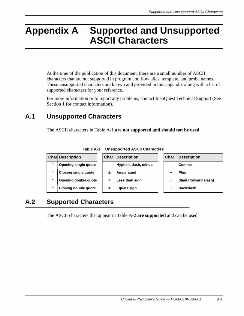
Supported and Unsupported ASCII Characters
Appendix A Supported and Unsupported ASCII Characters
At the time of the publication of this document, there are a small number of ASCII characters that are not supported in program and flow alias, template, and probe names. These unsupported characters are known and provided in this appendix along with a list of supported characters for your reference.
For more information or to report any problems, contact IneoQuest Technical Support (See Section 1 for contact information).
A.1 Unsupported Characters
The ASCII characters in Table A-1 are not supported and should not be used.
A.2 Supported Characters
The ASCII characters that appear in Table A-2 are supported and can be used.
Table A-1: Unsupported ASCII Characters
Char Description Char Description Char Description
` Opening single quote - Hyphen, dash, minus , Comma
´ Closing single quote & Ampersand + Plus
“ Opening double quote < Less than sign / Slant (forward slash)
” Closing double quote = Equals sign \ Backslash
Cricket 8-VSB User’s Guide — HUG-CT8VSB-001 A-1

Supported and Unsupported ASCII CharactersSupported and Unsupported ASCII Characters
Table A-2: Supported ASCII Characters
Char Description Char Description Char Description
(sp) Space @ At-sign a Lowercase a
! Exclamation mark A Uppercase A b Lowercase b
# Cross hatch (number sign) B Uppercase B c Lowercase c
$ Dollar sign C Uppercase C d Lowercase d
% Percent sign D Uppercase D e Lowercase e
( Opening parentheses E Uppercase E f Lowercase f
) Closing parentheses F Uppercase F g Lowercase g
* Asterisk G Uppercase G h Lowercase h
. Period H Uppercase H i Lowercase i
0 Zero I Uppercase I j Lowercase j
1 One J Uppercase J k Lowercase k
2 Two K Uppercase K l Lowercase l
3 Three L Uppercase L m Lowercase m
4 Four M Uppercase M n Lowercase n
5 Five N Uppercase N o Lowercase o
6 Six O Uppercase O p Lowercase p
7 Seven P Uppercase P q Lowercase q
8 Eight Q Uppercase Q r Lowercase r
9 Nine R Uppercase R s Lowercase s
: Colon S Uppercase S t Lowercase t
; Semicolon T Uppercase T u Lowercase u
> Greater than sign U Uppercase U v Lowercase v
? Question mark V Uppercase V w Lowercase w
[ Opening Sqr. bracket W Uppercase W x Lowercase x
] Closing Sqr. bracket X Uppercase X y Lowercase y
{ Opening curly brace Y Uppercase Y z Lowercase z
} Closing curly brace Z Uppercase Z ~ Tilde (approximate)
| Vertical line ^ Caret (Circumflex)
A-2 Cricket 8-VSB User’s Guide — HUG-CT8VSB-001

Glossary of Terms
Glossary of Terms
AARP: Address Resolution Protocol The
standard method for finding a host's hardware addresswhen only its network layer address is known.
ASI or DVB-ASI: Asynchronous Serial Interface The physical interface that is designed totransport video transport streams serially over coaxcable at up to 270Mb/s. DVB is a family of Europeandigital video standards.
BER Bit Error Rate is the number of erroneous bitsreceived divided by the total number of bitstransmitted.
CCRC Error Cyclic redundancy check error is the
receipt of data which does not match the cyclicredundancy check validation process.
DdBmV Decibels relative to one millivolt
FFEC Forward Error Correction is a communications
technique that is used to correct errored data on thereceiving end. Before transmission, the outgoing datais processed through an algorithm that adds extra bitsthat are used for error correction. If the transmittedmessage is received in error, the correction bits areused to repair it.
IIP Multicast: Internet Protocol Multicast IP
Multicast delivers source traffic to a group of receiverswithout adding any additional burden on the source orthe receivers while using the least network bandwidthof any competing technology. Multicast packets arereplicated in the network resulting in the most efficientdelivery of data to multiple receivers possible. Allalternatives require the source to send more than onecopy of the data.
IGMP: Internet Group Management Protocol (ver 1,2) (as per RFCs 1112/2236) IGMP is used todynamically register individual hosts in a multicastgroup on a particular LAN. Hosts identify groupmemberships by sending IGMP messages to their localmulticast router. Under IGMP, routers listen to IGMPmessages and periodically send out queries to discoverwhich groups are active or inactive on a particularsubnet.
IP-SBR: IP Stream Bitrate The IP Stream Bitrateis the measured data (payload) per second of a givenmedia over IP stream. The type of the payload is notconsidered, just the amount of payload in bytes ismeasured.
MMDI-DF: Delay Factor Delay Factor is a metric
which characterizes IP Packet cumulative jitter anddelay. The DF is the amount of buffer, in milliseconds,that would be required to subtract IP packet arrivaldeviations from the rate determined by the mediapayload.
MDI-MLR: Media Loss Rate Media Loss Rate isthe number of media packets lost per second.
MDI-MLT: Media Loss Total Media Loss Total isthe total number of media packets lost for a giveninspection period.
MDI-MLT-15: Media Loss Total-15 Media LossTotal is the total number of media packets lost for thecurrent 15-minute inspection period.
MDI-MLT-24: Media Loss Total-24 Media LossTotal is the total number of media packets lost for theprevious 24 hour inspection period. It provides ahistory of the last 96 15-minute inspection periods.
MDI-VB: Virtual Buffer Virtual Buffer is the sameas DF expressed in bytes for a given media stream rate.The VB is the amount of buffer, in bytes, that would berequired to subtract IP packet arrival deviations fromthe rate determined by the media payload.
MER Modulation Error Ratio is the ratio, in decibels, ofaverage symbol power to average error power.
MLS: Media Loss Seconds Media Loss Secondsis the total number seconds that saw a loss of mediapackets from the time the stream was recognized.
Cricket 8-VSB User’s Guide — HUG-CT8VSB-001 GL-1
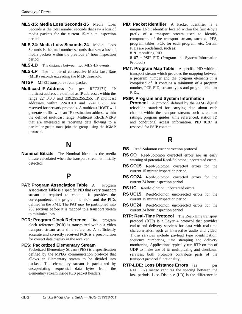
Glossary of Terms
MLS-15: Media Loss Seconds-15 Media LossSeconds is the total number seconds that saw a loss ofmedia packets for the current 15-minute inspectionperiod.
MLS-24: Media Loss Seconds-24 Media LossSeconds is the total number seconds that saw a loss ofmedia packets within the previous 24 hour inspectionperiod.
MLS-LD The distance between two MLS-LP events.
MLS-LP The number of consecutive Media Loss Rate(MLR) seconds exceeding the MLR threshold.
MTSP MPEG transport stream packet
Multicast IP Address (as per RFC3171) IPmulticast address are defined as IP addresses within therange 224.0.0.0 and 239.255.255.255. IP multicastaddresses within 224.0.0.0 and 224.0.0.255 arereserved for network protocols. A multicast HOST willgenerate traffic with an IP destination address withinthe defined multicast range. Multicast RECEIVERSthat are interested in receiving data flowing to aparticular group must join the group using the IGMPprotocol.
NNominal Bitrate The Nominal bitrate is the media
bitrate calculated when the transport stream is initiallydetected.
PPAT: Program Association Table A Program
Association Table is a specific PID that every transportstream is required to contain. It provides thecorrespondence the program numbers and the PIDsdefined in the PMT. The PAT may be partitioned into255 sections before it is mapped to a transport streamto minimize loss.
PCR: Program Clock Reference The programclock reference (PCR) is transmitted within a videotransport stream as a time reference. A sufficientlyaccurate and correctly received PCR is a preconditionfor correct data display in the receiver.
PES: Packetized Elementary StreamPacketized Elementary Stream (PES) is a specificationdefined by the MPEG communication protocol thatallows an Elementary stream to be divided intopackets. The elementary stream is packetized byencapsulating sequential data bytes from theelementary stream inside PES packet headers.
PID: Packet Identifier A Packet Identifier is aunique 13-bit identifier located within the first 4-byteprefix of a transport stream used to identifycomponents of the transport stream, such as PES,program tables, PCR for each program, etc. CertainPIDs are predefined, such as:8191 = stuffing PID8187 = PSIP PID (Program and System InformationProtocol)
PMT: Program Map Table A specific PID within atransport stream which provides the mapping betweena program number and the program elements it iscomprised of. It contains a minimum of a programnumber, PCR PID, stream types and program elementPIDs.
PSIP: Program and System Information Protocol A protocol defined by the ATSC digitaltelevision standard for carrying data about eachchannel within the transport stream; such as contentratings, program guides, time referenced, station IDand conditional access information. PID 8187 isreserved for PSIP content.
RRS Reed-Solomon error correction protocol
RS CO Reed-Solomon corrected errors are an earlywarning of potential Reed-Solomon uncorrected errors.
RS CO15 Reed-Solomon corrected errors for thecurrent 15 minute inspection period
RS CO24 Reed-Solomon corrected errors for thecurrent 24 hour inspection period
RS UC Reed-Solomon uncorrected errors
RS UC15 Reed-Solomon uncorrected errors for thecurrent 15 minute inspection period
RS UC24 Reed-Solomon uncorrected errors for thecurrent 24 hour inspection period
RTP: Real-Time Protocol The Real-Time transportprotocol (RTP) is a Layer 4 protocol that providesend-to-end delivery services for data with real-timecharacteristics, such as interactive audio and video.Those services include payload type identification,sequence numbering, time stamping and deliverymonitoring. Applications typically run RTP on top ofUDP to make use of its multiplexing and checksumservices; both protocols contribute parts of thetransport protocol functionality.
RTP-LDE: Loss Distance Errors (as perRFC3357) metric captures the spacing between theloss periods. Loss Distance (LD) is the difference in
GL-2 Cricket 8-VSB User’s Guide — HUG-CT8VSB-001
Glossary of Terms
sequence numbers of two successively lost packets,which may or may not be separated by successfullyreceived packets. LDE is the total number of LDerrors.
RTP-LPE: Loss Period Errors (as per RFC3357)metric captures the frequency and length of RTPpacket loss once it starts. LPE is the total number ofLoss Period errors.
RTP-SE: Sequence Errors (as per RFC3357)metric captures the total lost packets given thedifference in sequence numbers of two successivepackets of a RTP stream.
RVL: Remote Video Link A 10/100/1000 Ethernetport on select IneoQuest equipment that allows anyvideo IP stream traffic entering the unit to beforwarded out this port for other uses. The RVL portcan also modify the IP header of the selected IP stream,at line rate, not changing the IP stream behavior.
SSNTP Simple Network Time Protocol is a less complex
form of Network Time Protocol that does not requirestoring information about previous communications.
TTAP Test Access Port
Total CC Errors: Total Continuity Count Errors The Total Continuity Count Errors is thetotal number of errors in the MPEG transport streamfor the given inspection period, based on the 4-bitcontinuity counter in the MPEG transport stream.
Total PID/Mon/Err: Total number of Transport Stream PIDs/Monitored/Errored Totalnumber of PIDs within the MPEG transport stream, asdetected in the Program Table/ Total number of PIDswithin the transport stream currently being monitoredby system resources/ Total number of PIDs beingmonitored that are currently seeing errors.
VV-TSB: Video Transport Stream Bitrate The
Video Transport Stream Bitrate is the measured bitrateof the encapsulated video transport stream within an IPstream. The arrival data rate of the IP packets is notconsidered. This measurement looks at the videotransport stream payload bitrate by inspecting thePCRs within the transport stream being carried by theIP packets.
ZZAP: ZAP Time Time which it takes for a Multicast
group stream to appear at a destination after an IGMPjoin is issued from the destination. For certain Videoover IP applications, that use multicast groups totransport video, this can be referred to as channelchange time.
Cricket 8-VSB User’s Guide — HUG-CT8VSB-001 GL-3

Glossary of Terms
GL-4 Cricket 8-VSB User’s Guide — HUG-CT8VSB-001

Index
AAuto Upload 9-11
BBlack Cells 7-2
CCharacteristics, Channel Alias 10-2Configure system-wide parameters 8-13
DDate and Time Adjustments 8-23Defined Users 8-18
FFilters 9-8Firmware version 6-3Flow Census 9-4
GGlobal Parameters, Description 6-7Gray Cells 7-2Green Cells 7-2
HHTTP 8-20
IICMP 8-20Identifiers 10-4IQ Tools 8-21iVMS Configuration 8-15iVMS Configuration, Description 6-4, 6-5
MManagement Port 8-11
NNew Account 8-18
Ppassword 6-1Port Configuration, Description 6-6Program Media Loss (CC) Alarms 10-7Program Monitoring Alarms 10-8Program Monitoring Template 10-5Program PID Bitrate Monitoring Alarms 10-10
RRed Cells 7-2RF Flow Alias Template 10-2RMON Statistics 12-5Round Trip Time 12-6
SSNMP Configuration 8-14SNMP Configuration, Description 6-4SYSLOG Configuration, Description 6-5System Identification 8-13System Location 8-14System Memo 8-13System Status, Description 6-3System Uptime 6-3
TTelnet 8-20Time Source 8-22Trace Route 12-8Transport Streams 9-5Triggers 9-7Tuner Configuration 6-8, 8-1Tuner Map Upload/Download 8-7Tuner Parameters 8-4Tuner RF Channels 8-6
UUSB Driver, Installation 5-1User PID Monitoring Rules 10-9username 6-1
VVideo Transport Alarm Template 10-12Video/Program Alarm Template 10-6
YYellow Cells 7-2
Cricket 8-VSB User’s Guide — HUG-CT8VSB-001 Index-1

Index-2 Cricket 8-VSB User’s Guide — HUG-CT8VSB-001