cp40ii instruction manual complete - ict international
TRANSCRIPT

InstructionInstruction ManualManual
Cone PenetrometerCone Penetrometer
Manufactured by:Manufactured by:

Manufactured by:
Rimik
1079 Ruthven St
Toowoomba QLD 4350
Australia
Ph. +61 438 135 215
Http://www.rimik.com

2
1. Warranty Term Subject to the conditions set out below, Rimik warrants to the original purchaser that: 1.1 The Product will be free from defects in workmanship and materials under normal use
for a period of 1 year from the date of purchase. 2. Warranty Conditions 2.1 This warranty covers all parts found to be defective in workmanship and/or materials
during the warranty period and will be repaired or replaced at the discretion of the manufacturer. Parts replaced will not be returned.
2.2 Rimik will not be responsible for any costs in connection with freight or postage of replacement products or parts.
2.3 This warranty will be void and accordingly no claim of any nature whatsoever will be enforceable against the manufacturer if the product is not installed and operated ac- cording to the printed instructions supplied with the product or if the product is sub- jected to abuse, neglect, misuse or an accident.
2.4 The manufacturer and/or distributor will not be liable for any incidental or consequen- tial loss or damage arising from any cause whatsoever including but not limited to loss or damage arising from the installation or operation of the product and/or the
failure of any part for any reason whatsoever. 2.5 There are no warranties expressed or implied except those stipulated above.

3
Contents
Introduction 4 Controls - front panel 4 - rear panel 5 Features 6 Understanding Parameter Settings 7 Setting Up 8 Power on, power off 8 Date 8 Time 8 Parameters 9 Inserts/file 9 Speed abort 9 Max depth 9 Interval 9 Max speed 9 Cone size 9 GPS 10 Installing the Software (Windows 95 on) 10 Setting up for an Insertion 10 Cone wear 10 Using the Penetrometer Recording Insertions 11 Site name 11 Performing the Insertion 11 Reviewing Data 12 Downloading Data to PC 12 Viewing Data on PC 12 Clearing the Memory 12 Troubleshooting 13 Appendix A 15 Load Calibration 15 Distance Calibration 16 Checking the Load 16 Checking the Distance 16 Appendix B 17 Optional GPS Receiver 17 GPS Receiver 17 GPS Receiver Configuration & Connection 17 Battery 19 Load Cell Connection 19 Download Cable Connection 19 Specifications 20
4
Introduction
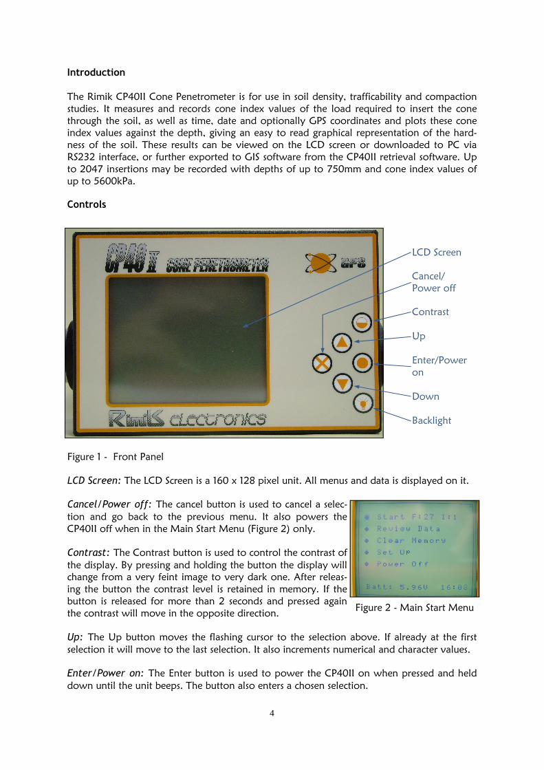
The Rimik CP40II Cone Penetrometer is for use in soil density, trafficability and compaction studies. It measures and records cone index values of the load required to insert the cone through the soil, as well as time, date and optionally GPS coordinates and plots these cone index values against the depth, giving an easy to read graphical representation of the hard-ness of the soil. These results can be viewed on the LCD screen or downloaded to PC via RS232 interface, or further exported to GIS software from the CP40II retrieval software. Up to 2047 insertions may be recorded with depths of up to 750mm and cone index values of up to 5600kPa. Controls
LCD Screen
Cancel/ Power off
Contrast Up Enter/Power on Down Backlight
Figure 1 - Front Panel LCD Screen: The LCD Screen is a 160 x 128 pixel unit. All menus and data is displayed on it.
Cancel/Power off: The cancel button is used to cancel a selec-tion and go back to the previous menu. It also powers the CP40II off when in the Main Start Menu (Figure 2) only. Contrast: The Contrast button is used to control the contrast of the display. By pressing and holding the button the display will change from a very feint image to very dark one. After releas-ing the button the contrast level is retained in memory. If the button is released for more than 2 seconds and pressed again the contrast will move in the opposite direction. Up: The Up button moves the flashing cursor to the selection above. If already at the first selection it will move to the last selection. It also increments numerical and character values. Enter/Power on: The Enter button is used to power the CP40II on when pressed and held down until the unit beeps. The button also enters a chosen selection.
Figure 2 - Main Start Menu

5
Down: The Down button moves the flashing cursor to the selection below. If already at the last selection it will move to the first selection. It also decrements numerical and character values.
Backlight: The backlight button is used to turn the backlight on and off each time the button is pressed. It will only work in the menus and not in the page that displays the model and serial number on start up. The backlight on, decreases battery life and is indicated by a small ‘x’ in the top right hand corner (Figure 3) of the display. Figure 3
DC Power Socket PC Connector Transducer GPS Connector Reset Switch Load Cell Load Cell Connector
Figure 4 - Rear Panel DC Power Socket: This DC Power Socket is used to connect the CP40II to an external 6V bat-tery charger to recharge the internal 6V battery. PC Connector (RS232): This DB9 socket is used to connect the CP40II to a PC to download insertion data and upload settings from the supplied Retrieval Software. Transducer: The Ultrasonic Transducer is used to measure the distance to the target by send-ing and receiving ultrasonic waves. GPS Connector: The GPS Connector is used to connect and power the optional external GPS receiver to the CP40II, enabling GPS coordinates to be attached to each insertion file. Reset Switch: The Reset Switch is used to force the CP40II into the power off state. Nor-mally, it is powered off by the Cancel/Power off button on the front panel. However be-cause it is kept in the power on state by the CPU and not simply a physical switch, there is a remote possibility that in the event of some malfunction occurring, the unit can still be forced into the power off state. Load Cell: The Load Cell responds to the force required to insert the cone into the soil and sends a corresponding result back for the CP40II to record.

6
Load Cell Connector: The Load Cell Connector is used to connect the load cell to the unit to record the force exerted by the shaft. It should never need to be disconnected by the user.
Features Included Items & Accessories
1 x Pelican Case with Foam Insert 1 x CP40II 1 x Shaft (2 pieces) 1 x Small Cone 1 x Large Cone 1 x Target with Bush 2 x Handles 2 x Knobs for Handles 2 x Knobs for GPS Bracket 2 x 8mm Spanner 1 x 13mm Spanner 1 x ASAE Cone Wear Gauge 1 x Serial Cable 1 x Test Stand Bolt 1 x Serial Number Sticker, on CP40II 1 x Users Manual 1 x CD (retrieval software & manual) 1 x Warranty Card
Accessories included without GPS
1 x GPS Connector 1 x GPS Mounting Bracket 2 x Grub Screws, already fitted 1 x 2.5mm Allen Key Accessories included with GPS
1 x Garmin GPS Receiver, connector fitted 1 x GPS Mounting Bracket, GPS fitted Other included Accessories
1 x 240V SLA Battery Charger 1 x European Mains Pin Adaptor, (Europe only) 1 x Battery Charger Connector, (110-130V)
Cone Wear Gauge Small Cone Large Cone
Target
Test Stand Bolt
Knobs for
GPS Bracket
8mm
Spanners
13mm Spanner
Shaft Pieces Serial Download Cable Handles Knobs for Handles
Figure 5 - Included Accessories

7
GPS Mounting
Bracket
Grub Screws
Allen Key
European Mains Pin
Adaptor
GPS Battery Charger Connector 240V SLA Battery Charger GPS Connector
Figure 6 - Other Optional Accessories
Understanding Parameter Settings Inserts/File
The CP40II is capable of recording up to 2047 insertions. An insertion is the act of using the CP40II to insert the cone into the soil to obtain a profile of soil cone index values. These in-sertions can be grouped into files of 1 to 9 insertions, for the purpose of, for example, taking a set number of insertions per block of land. This set of insertions, now being a file, can be averaged by the retrieval software to achieve one profile of the soil cone index values per block of land. Interval
While performing an insertion, the CP40II is taking readings from both the load cell and the ultrasonic transducer at the rate of 40 readings per second. The CP40II then averages those results and stores the average as the data for that interval. If the interval was set 20mm, then the CP40II would take readings from 0 to 20mm depth and average them for the first inter-val, 20 to 40mm for the second interval and so on until the last interval is recorded at the end of the insertion. The reason it does this is because the soil can have small pockets of air, stones, sticks or roots etc, which will cause the cone index value to jitter around the true reading for the soil. Max Speed
Because the standards associated with the method of measuring the soil density that the CP40II uses, recommends a minimum speed of 0.2 metres per minute and a maximum speed of 2 metres per minute, the CP40II has been included with this setting, which once set, will emit an audible beep if the maximum speed of insertion is exceeded. This lets the user know that the cone index values may not be an accurate representation of the actual soil density profile. Max Depth
The Max Depth is the depth at which the CP40II will complete an insertion. It can be set to a maximum of 750mm.

8
Speed Abort
This setting, if turned on, uses the maximum speed set, as the limit to abort an insertion, in-stead of giving the audible warning. This ensures that the cone index values are correct, if the maximum speed is set to the correct value. Cone Size
The CP40II uses both ASAE cone sizes, (130mm² & 323mm²) areas. The larger cone is used for softer soils and allows the CP40II to measure up to 2200kPa pressure. The smaller cone is used for harder soils and allows the CP40II to measure up to 5600kPa pressure. The larger cone will give better accuracy in softer soils that don’t exceed 2200kPa. Both of these pres-sure ratings correspond to 75kg of mass pushing the cone into the soil, if this 75kg is ex-ceeded the CP40II will abort the insertion and ask you if you would like to keep the data. Setting Up Power on
To turn the CP40II on, simply press and hold the ‘Enter’ button until the unit beeps. The first thing it will display on the LCD Screen is the model, version and serial number, before chang-ing to the main start menu. Power off To turn the CP40II off, simply press the ‘Cancel’ button while the main start menu is dis-played. The ‘Cancel’ button will not turn the unit off in any other menu, but rather it will go back to the preceding menu. Date (Set Up -> Date) Each time an insertion is made, the date is attached to the insertion data. This enables the user to determine when each insertion was made. The user can select to display the date for-mat as either D/M/Y or M/D/Y. To set the date, move the flashing cursor over ‘• Date’ and press ‘Enter’, the cursor will now be flashing on the date format, next use the ‘Up’ or ‘Down’ buttons to change which format, and press ‘Enter’. The cursor will now be flashing on either the day of the month or the month of the year, depending on which format was selected. Use the ‘Up’ or ‘Down’ but-tons to change this value, then press ‘Enter’. In the same way, use the ‘Up’, ‘Down’ and ‘Enter’ buttons to select the remaining values. The date is updated by an internal clock, which will keep running for several days after the unit is powered off. However if the unit is turned off for an extended time it will lose the date and will have to be reset. The time can also be synced with the PC clock, (see the re-trieval software manual supplied on CD). Time (Set Up -> Time) Each time an insertion is made the time is attached to the insertion data. This enables the user to determine when each insertion was made. The CP40II uses a 24hour clock only, this means that, for example 3.00pm is displayed as 15.00 hours. To set the time move the flashing cursor over ‘• Time’ and press ‘Enter’. The cursor will now be flashing over the hours, next use the ‘Up’ or ‘Down’ buttons to change the hour and press ‘Enter’ to select. In the same way, use the ‘Up’, ‘Down’ and ‘Enter’ buttons to select the re-maining values. The time is updated by an internal clock, which will keep running for several days after the unit is powered off. However if the unit is turned off for an extended time it will lose the time and will have to be reset. The time can also be synced with the PC clock, (see the re-trieval software manual supplied on CD).

9
Parameters (Set Up -> Parameters) The parameter menu allows the user to change and select the following settings associated with the actual insertion, explanations of these parameters is found above on page 8. To set the chosen parameter, move the flashing cursor over it and press ‘Enter’. The cursor will now be flashing over the value, use the ‘Up’ or ‘Down’ buttons to change the value and press ‘Enter’ to select. When all the desired parameters have been set, press ‘Cancel’ to return to the previous menu. The Parameters can also be set via the PC, (see the retrieval software manual supplied on CD). Inserts/File (Set Up -> Parameters -> Inserts/File) The Inserts/File may be set from a minimum of 1 to a maximum of 9 insertions per file. The unit will not allow this setting to be changed unless the unit is ready to start a new file num-ber, i.e. the current insertion number in the main start menu must be 1. This is to preserve the averaging facility in the retrieval software. To determine if the unit is at the beginning of a file, the main start menu displays the file and insertion numbers of the next insertion to be taken, next to the ’• Start’. ‘I’ must equal 1. Interval (Set Up -> Parameters -> Interval) The Interval can be set to either 10,15,20 or 25mm. The unit will not allow this setting to be changed unless the unit is ready to start a new file number, i.e. the current insertion number in the main start menu must be 1. Max Depth (Set Up -> Parameters -> Max Depth) The Maximum Depth may be set from a minimum depth of one interval to a maximum depth of 750mm in whole increments of intervals. Therefore depending on what the interval is set at, will determine the choice of maximum depth. The unit will not allow this setting to be changed unless the unit is ready to start a new file number, i.e. the current insertion num-ber in the main start menu must be 1. Max Speed (Set Up -> Parameters -> Max Speed) The Max Speed may be set in whole numbers, from 1 to 8 metres per minute. This then de-termines at what speed the audible beep is heard, letting the user know when they have ex-ceeded the maximum speed set, or alternatively abort the insertion if the speed abort is turned on. While performing the insertion, the unit displays the current speed to give the user a real time guide to keep a constant speed of insertion. Speed Abort (Set Up -> Parameters -> Speed Abort) If this feature is turned on, instead of the CP40II giving an audible warning, it will instead abort the insertion and not record the data.
Cone Size (Set Up -> Parameters -> Cone) The user may select the small ASAE 130mm² cone or the large ASAE 323mm² cone, to suit the hardness of the soil.

10
GPS (Set Up -> GPS) The CP40II can be optionally fitted with a GPS receiver, to record position information with every insertion. The GPS setting can be set on or off, if set on, the CP40II looks for the GPS information before allowing the insertion to take place. On cold start up this may take a cou-ple minutes, but once the GPS is navigating the GPS information should update in less than 30 seconds. To set GPS on or off, move the flashing cursor over ‘• GPS’ and press ‘Enter’, the cursor will now be flashing over ‘GPS navigating’ or ‘GPS not navigating,’ depending on which is cur-rently selected, next use the ‘Up’ or ‘Down’ buttons to change the setting and press ‘Enter’. Specifications on the GPS supplied can be found in Appendix B in the back of this manual. Installing the Software, (windows 95 on)
Insert the CP40II CD into the CD drive and provided you have auto run turned on, on your PC, it will automatically run the setup procedure. All the user will have to do then is follow the prompts. If you don’t specify where you would like the software installed, it will save it in C:\Programs\CP40II. If auto run is not turned on, click on the ‘Start’ button, click on ‘Run’ and type in D:\CP40IIinstall.exe, where ’D’ is your CD rom drive, and click ‘OK’. Then simply follow the prompts. If you don’t specify where you would like the software installed, it will save it in C:\Programs\CP40II. Setting Up for an Insertion
After setting the Parameters, check that the cone about to be used isn’t worn out, (see Cone Wear below). Attach the handles and tighten the knobs finger tight. Assemble the 2 piece shaft onto the load cell, just hand tight, they will only go on one way. Then before attaching the desired cone, push the target onto the shaft. Once the shaft, cone and target are assem-bled, gently tighten the shafts to the load cell and the cone to the shaft. They do not need to be really tight, this will just wear out the spanners and the flats on the shafts and cone. Just a nudge is all that is required to stop them coming loose. Reverse this procedure to disassemble the shaft assembly. A demonstration video on shaft assembly procedure can be found on the CD supplied. Please Note: it is recommended that the user regularly check that the cone and shaft assem-bly hasn’t come loose in any of the assembly points, when doing multiple insertions. There is always a chance the shaft assembly could come loose, if this happens, there is a much greater chance of the shaft breaking and severe injury resulting to the user. If the GPS is required, attach the GPS unit, tightening the knobs finger tight and connecting the plug to the GPS connector socket, (line up the plug, push it on and turn the locking piece clockwise, reverse procedure for disassembly). Cone Wear
Excessive wear to the cone will cause incorrect readings of the soil density profile. A Cone Wear Guide has been supplied for the user to check that cone wear hasn’t exceeded the limit for accuracy. If the small cone slips through the small hole, see Figure 7, the cone must be discarded, likewise, if the large cone slips through the large hole it must be discarded. The cone is outside the 5% tolerance specified by the ASAE standard. The cone wear guide also has cutouts for the user to check that the sides of the cones have not deformed excessively, as this can also give incorrect readings of the soil. The cone should also be discarded if this check shows the sides are exces-sively deformed.
Figure 7 - Cone Wear Guide

11
Using the CP40II Penetrometer Recording Insertions
Site Name (Set Up -> Site Name) Whenever the user does an insertion, the CP40II will record the currently set Site Name with each insertion. If the site name is to be different for the next insertion, it must be changed prior to doing the insertion. To set the site name, move the flashing cursor over ‘• Site Name’ using the ‘Up’ or ‘Down’ buttons and press ‘Enter,’ the CP40II will display the current site name with the cursor flash-ing over the first character. To change the character, use the ‘Up’ or ‘Down’ buttons to select the chosen character and press ‘Enter,’ the cursor will move onto the next character. Repeat this process until the desired site name is entered, then press ‘Cancel’ to return to the previ-ous menu with the new site name set for the next insertion. Performing the Insertion (Start) Once the CP40II has been assembled ready for an insertion, (see previous page on Setting up for an Insertion and Cone Wear), the insertion can be performed by a single user. Place the target over the selected spot, making sure the target sits reasonably level. Remove any foliage from around the shaft and target, this ensures the ultrasonic transducer will not pick up any incorrect depth fluctuations due to the foliage reflecting the ultrasonic waves. Keeping the target on the ground, hold the weight of the CP40II to stop the cone from sink-ing into the soil, the cone needs to be above the ground to start the insertion, otherwise the CP40II will show the error message ‘Too Close, Data not Recorded!’ Once the insertion is started, push the cone through the soil vertically, putting no sideways/lateral force against the shaft following the hole made by the cone, smoothly and at a constant speed, aiming for 2 metres per minute or less, (the speed is displayed on the LCD screen during the insertion), until the insertion is finished at the maximum depth selected. For a demonstration video, see the supplied CD. To record an insertion, use the ‘Up’ or ‘Down’ button to move the flashing cursor over ‘• Start’ in the main start menu and press the ‘Enter’ button, The F:X beside ‘• Start’ denotes the next file number and I:X denotes the next insertion number within the file. The CP40II will now execute one of several options depending on the GPS setting and the response of the GPS receiver: If GPS is selected, the CP40II will now obtain navigational data from the GPS receiver, if it has a navigational fix the CP40II will display ‘Navigating GPS’ on the top line, next below will be displayed the absolute latitude and longitude in degrees, minutes and seconds. Next below that, will be displayed the local latitude and longitude in metres. On the bottom of the screen is ‘Enter to start insertion.’ ‘Enter’ may need to be held down for up to 1 second to give the CP40II time to record the navigational data to the insertion file. ‘Navigating DGPS’ may be displayed instead of ‘Navigating GPS’, this simply means the GPS has found extra Satellite information to obtain a more accurate ‘fix’ to within 3-5 metres, using the optional GPS supplied. Standard ‘GPS’ is to within 15 metre accuracy. If GPS is selected and the GPS receiver is unable to get a navigational fix, the CP40II will dis-play ’Not Navigating’ and ’Enter to start insertion.’ if the ‘Enter’ button and is pressed, (it may need to be held down for up to 1 second) the CP40II will go ahead with the insertion, but since there is no navigational data, the latitude and longitude will be recorded as 0. If GPS is selected and the GPS receiver is not sending any valid navigational data, or there is no GPS receiver plugged in, the CP40II will display ’No Valid Data’ and ’Enter to start inser-tion.’ if the ‘Enter’ button and is pressed, (it may need to be held down for up to 1 second)

12
the CP40II will go ahead with the insertion, but since there is no valid navigational data, the latitude and longitude will be recorded as 0. If GPS is not selected, the CP40II will start the insertion immediately. Since there is no valid navigational data, the latitude and longitude will be recorded as 0. Once the insertion has initiated, the ultrasonic transducer will emit a clicking sound as it pro-duces the ultrasonic waves. The LCD screen will display the depth of the cone below ground (as a positive number), and before the cone is inserted this number will be negative. Also dis-played during the insertion is the current cone index in kPa, the insertion speed in metres per minute and which interval is currently being recorded. The user can abort an insertion by pressing the ‘Cancel’ button and the LCD screen will display ‘Insertion Aborted, Data not Re-corded!’ When the insertion has completed, the CP40II will automatically enter the review data menu selection to show the insertion just recorded in graphical form. Pressing ‘Enter’ or ‘Cancel’ will take the user to the main start menu ready for the next insertion. Reviewing Data (Review Data) The CP40II provides the user with the ability to review the insertions stored in memory. To review insertions stored, move the flashing cursor over ‘• Review Data’ using the ‘Up’ or ‘Down’ buttons and press ‘Enter,’ the cursor will now be flashing over the last file number, use the ‘Up’ or ‘Down’ buttons to choose which file to review and press ‘Enter.’ The chosen file will be displayed in graphical form, with depth being the X axis and each graticule indi-cating one interval. The Y axis displays the cone index reading with each graticule indicating 250kPa. The CP40II dynamically adjusts the X axis to suit the maximum depth and the Y axis to suit the maximum cone index reading possible for the cone used. While reviewing the file the CP40II allows the ‘Up’ and ‘Down’ buttons to increment and decrement the insertions on display. Press ‘Cancel’ to return to the main menu. Downloading Data to PC
To download the insertion data from the CP40II, connect the data cable between your PC and the CP40II, open the installed retrieval software on PC, click on download, then on start, select which files to download and the retrieval software will temporarily take control of the CP40II to download the insertion data. Alternatively, see the CP40II retrieval software help file. Viewing Data on PC
Once the insertion data has been downloaded, the user can select which file to display. Once the file is selected, the individual insertions within the file can be selectively displayed with depth in millimeters on the X axis and force in kPa on the Y axis. The file number, insertion number, site name, depth, interval size, cone used, navigational data, time and date is dis-played in the bottom left of the screen. The user also has the ability to zoom in and out using the ‘A’ and ‘Z’ keys; move the graph up, down, left and right using the arrow keys and ro-tate the graph. Clear Memory (Clear Memory) The Clear Memory option clears every insertion file stored in the CP40II, it does not delete the site name or insertion parameters. To clear the memory, move the flashing cursor over ‘• Clear Memory’ using the ‘Up’ or ‘Down’ buttons and press ‘Enter.’ ‘Clear Data?’ will be displayed, then if ‘Cancel’ is pressed it will return to the main start menu without clearing the data, if ‘Enter’ is pressed the data will be erased and the CP40II will return to the main start menu.

13
Troubleshooting
Error/ Error Message Cause Remedy
Beeps while performing an insertion.
Maximum speed has been exceeded.
Keep a slower constant speed of insertion. Increase the max speed set-ting.
Displays very large local ori-gin numbers.
Local origin has not been set. Set Local origin. CP40II loses local origin if powered off.
Insert aborted, keep data? Maximum Load exceeded. Maximum Speed exceeded. Minimum Speed exceeded. Too Close. Cancel button pressed.
See Max Load exceeded. See Too fast. See Too slow. See Too Close.
Insertion doesn’t complete. Distance not correctly cali-brated.
Calibrate distance. See Ap-pendix A.
Low battery, CP40 power off.
Battery voltage has fallen be-low 5.5V.
Recharge battery.
Max Load exceeded. Maximum load of 75kg has been exceeded.
Keep a slower constant speed of insertion. Use a smaller cone.
Memory full. In built memory of 2047 in-sertions has been used.
Download data to PC and clear memory.
No data available. No insertions recorded in memory.
Record insertion.
No load recorded. Incorrect load calibration. Calibrate load. See Appendix A.
Not navigating. The GPS has not yet gained a navigational fix. Weather too overcast.
Wait for GPS to get naviga-tional fix. Try again on a clearer day.
No valid data. GPS selected but not plugged in. GPS not sending correct mes-sage to CP40II.
Check that GPS is plugged in correctly. GPS must be configured and connected properly. See Ap-pendix B.
Too close, data not recorded. Cone below ground at start of insertion. Dirt or mud built up around cone. Target not sitting on ground. Foliage around shaft reflect-ing ultrasonic waves. Incorrect distance calibration.
Keep cone raised slightly to start insertion. Clear clumps of grass or dirt from under target or around cone. Clear foliage from around shaft. Calibrate distance. See Ap-pendix A.

14
Too fast. Maximum set speed of inser-tion exceeded, speed abort is turned on. Incorrect distance calibration.
Keep a slower constant speed of insertion. Increase maximum speed set-ting. Turn speed abort off. Calibrate distance. See Ap-pendix A.
Too slow. Minimum speed of 0.2 metres per minute exceeded. Incorrect distance calibration.
Keep a faster constant speed of insertion. Calibrate distance. See Ap-pendix A.
Under PC control/ buttons don’t control CP40II.
PC has control of CP40II while communicating with it.
It is normal operation.
15
Appendix A
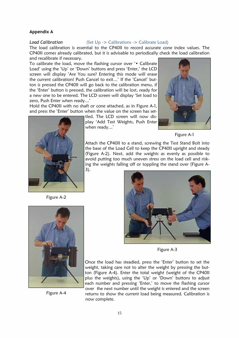
Load Calibration (Set Up -> Calibrations -> Calibrate Load) The load calibration is essential to the CP40II to record accurate cone index values. The CP40II comes already calibrated, but it is advisable to periodically check the load calibration and recalibrate if necessary. To calibrate the load, move the flashing cursor over ‘• Calibrate Load’ using the ‘Up’ or ‘Down’ buttons and press ‘Enter,’ the LCD screen will display ’Are You sure? Entering this mode will erase the current calibration! Push Cancel to exit…’ If the ’Cancel’ but-ton is pressed the CP40II will go back to the calibration menu, if the ‘Enter’ button is pressed, the calibration will be lost, ready for a new one to be entered. The LCD screen will display ‘Set load to zero, Push Enter when ready…’ Hold the CP40II with no shaft or cone attached, as in Figure A-1, and press the ‘Enter’ button when the value on the screen has set-
tled. The LCD screen will now dis-play ‘Add Test Weights, Push Enter when ready…’ Attach the CP40II to a stand, screwing the Test Stand Bolt into the base of the Load Cell to keep the CP40II upright and steady (Figure A-2). Next, add the weights as evenly as possible to avoid putting too much uneven stress on the load cell and risk-ing the weights falling off or toppling the stand over (Figure A-3).
Once the load has steadied, press the ‘Enter’ button to set the weight, taking care not to alter the weight by pressing the but-ton (Figure A-4). Enter the total weight (weight of the CP40II plus the weights), using the ‘Up’ or ‘Down’ buttons to adjust each number and pressing ‘Enter,’ to move the flashing cursor over the next number until the weight is entered and the screen returns to show the current load being measured. Calibration is
now complete.
Figure A-1
Figure A-3
Figure A-2
Figure A-4

16
Distance Calibration ( Set Up -> Calibrations -> Cal Distance) The distance calibration is essential to the CP40II to record accurate depth measurements. The CP40II comes already calibrated, but it is advisable to periodically check the distance calibration and recalibrate if necessary. To calibrate the distance, first assemble the CP40II, then move the flash-ing cursor over ‘• Cal Distance’ using the ‘Up’ or ‘Down’ buttons and press ‘Enter,’ the LCD screen will display ’Are You sure? Entering this mode will erase the current calibration! Push Cancel to exit…’ If the ’Cancel’ button is pressed the CP40II will go back to the calibration menu, if the ‘Enter’ button is pressed, the calibration will be lost and the cursor will be flashing over the value for the target height. Use the ‘Up’ or ‘Down’ buttons to select the target height and press ‘Enter,’ if using the standard target this value should be set to 35mm. The cursor will now be flashing over the value of the distance from the base of the cone to the ultrasonic transducer. Use the ‘Up’ or ‘Down’ buttons to select the distance and press ‘Enter,’ if using the standard shaft this value should be set to 963mm. Next you will hear the ultrasonic transducer operating, emitting a clicking sound, hold the assembled CP40II off the ground so that the target rests on the base of the cone, as shown in fig-ure A-5. The LCD screen will display ‘Steady CP40, press Enter when ready.’ Press ‘Enter’ once the CP40II is steady. Enter the distance using the ‘Up’ or ‘Down’ buttons to select the desired value and press ‘Enter,’ if using the standard shaft and target this value should be set to 957mm. The LCD screen will now display the current time, distance and depth being measured. Calibration is now complete.
Checking the Load (Set Up -> Calibrations -> Check Load) This function allows the user to check the load applied to the load cell. To check the load, move the flashing cursor over ‘• Check Load’ using the ‘Up’ or ‘Down’ buttons and press ‘Enter.’ The load will be displayed in kilograms. Checking the Distance (Set Up -> Calibrations -> Check Distance) This function allows the user to check the distance measured by the ultrasonic transducer. To check the distance, move the flashing cursor over ‘• Check Distance’ using the ‘Up’ or ‘Down’ buttons and press ‘Enter.’ The time (of flight of the ultrasonic wave), distance meas-ured and the depth calculated will be displayed in microseconds and millimeters respectively.
Figure A-5

17
Appendix B
Optional GPS Receiver Specifications (Garmin GPS16)
The optional GPS receiver is supplied configured, to automatically select between normal GPS and the more accurate DGPS, this is indicated as ’Navigating GPS’ or ’Navigating DGPS’ when the navigational information is displayed. This GPS receiver has an accuracy to within a 15 metre radius in normal GPS. If it as able to pick up additional information from extra sat-ellites it will automatically switch to DGPS and obtain a greater accuracy to within a 3-5 me-tre radius.
FCC Compliance: meets Part 15 of the FCC interference limits for Class B digital devices for home or office use. GPS Receiver Configuration & Connection
The CP40II is able to use any GPS receiver, provided it is configured and connected properly. The CP40II is set to read an NMEA 0183 output $GPGGA sentence at 1 second intervals with a baud rate of 4800bps, from the GPS connector. Any other message type, baud rate or in-terval greater than 1 second, will not work. If a GPS receiver other than the standard optional GPS receiver is to be used, it should be configured (as above) and connected by a competent professional to ensure it will work and no damage occur to either the CP40II or the GPS receiver. The typical connection used by the optional GPS receiver is shown in Figure B-1 below, where the enable is set high. For other GPS units which may need the enable set low, see Fig-ure B-2 below. If a GPS unit to be fitted uses a supply voltage other than +5V or a current draw of more than 150mA, the user will have to make provision for the GPS receiver to be powered external to the CP40II, see Figure B-3 below. For the purpose of configuring a GPS unit via a PC, see Figure B-4 below for connection.
GPS Accuracy Position: <15 metres, 95% (typical) Velocity: 0.1 knot RMS steady state DGPS (USCG/RTCM) Accuracy Position: 3-5 metres, 95% (typical) Velocity: 0.1 knot RMS steady state
DGPS (WAAS) Accuracy Position: <3 metres, 95% (typical) Velocity: 0.1 knot RMS steady state Acquisition Times Reacquisition: <2 seconds Warm: approximately 15 seconds Cold: approximately 45 seconds
Figure B-1

18
Figure B-2
Figure B-3
Figure B-4
19
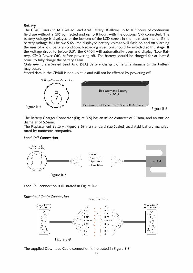
Figure B-5 Figure B-6
Figure B-7
Figure B-8
The Battery Charger Connector (Figure B-5) has an inside diameter of 2.1mm, and an outside diameter of 5.5mm. The Replacement Battery (Figure B-6) is a standard size Sealed Lead Acid battery manufac-tured by numerous companies.
Load Cell connection is illustrated in Figure B-7.
The supplied Download Cable connection is illustrated in Figure B-8.
Load Cell Connection
Download Cable Connection
Battery
The CP40II uses 6V 3AH Sealed Lead Acid Battery. It allows up to 11.5 hours of continuous field use without a GPS connected and up to 8 hours with the optional GPS connected. The battery voltage is displayed at the bottom of the LCD screen in the main start menu. If the battery voltage falls below 5.6V, the displayed battery voltage will flash on and off warning the user of a low battery condition. Recording insertions should be avoided at this stage. If the voltage drops to below 5.5V the CP40II will automatically beep and display ‘Low Bat-tery, CP40 Power Off’, before powering off. The battery should be charged for at least 8 hours to fully charge the battery again. Only ever use a Sealed Lead Acid (SLA) Battery charger, otherwise damage to the battery may occur. Stored data in the CP40II is non-volatile and will not be effected by powering off.

20
Specifications
Weight (assembled without GPS) (kg) Weight (in case) (kg) Dimensions (assembled without GPS) (mm) Case Dimensions (mm) Maximum Small Cone Index (kPa,kg) Maximum Large Cone Index (kPa,kg) Resolution (kg) Maximum Insertion Depth (mm) Interval Spacing (mm) Memory Capacity (no. of insertions) Operating Temperature (°C) Baud Rate/Download speed (bps) Screen Resolution (pixels) Battery Life (mAh) Conforms to Standard ASAE S313.3 feb99
Small Cone Size (dia.mm, area,mm²) Large Cone Size (dia.mm, area,mm²) Shaft Size (dia.mm)
3.9
9 560x1073x130
470 x 358 x 175 5600, 75 2200, 75
0.03 750
10,15,20,25 2047
-10-75 9600
160 x 128 3000
12.83, 130 20.27, 323
9.53

21