course material - miet · ee6603 power system operation and control l t p c 3 0 0 3 unit i...
TRANSCRIPT

1
M.I.E.T. ENGINEERING COLLEGE
(Approved by AICTE and Affiliated to Anna University Chennai)
TRICHY – PUDUKKOTTAI ROAD, TIRUCHIRAPPALLI – 620 007
DEPARTMENT OF ELECTRICAL AND
ELECTRONICS ENGINEERING
COURSE MATERIAL
EE6603 - POWER SYSTEM OPERATION AND CONTROL
III YEAR – VI SEMESTER

2
M.I.E.T. ENGINEERING COLLEGE
(Approved by AICTE and Affiliated to Anna University Chennai)
TRICHY – PUDUKKOTTAI ROAD, TIRUCHIRAPPALLI – 620 007
DEPARTMENT OF ELECTRICAL AND ELECTRONICS ENGINEERING (SYLLABUS)
Sub. Code : EE6603 Branch/Year/Sem : EEE/III/V
Sub Name : POWER SYSTEM OPERATION AND CONTROL Batch : 2016-2020
Staff Name : E.MUTHUKUMARAN Academic Year : 2019-2020
EE6603 POWER SYSTEM OPERATION AND CONTROL L T P C
3 0 0 3 UNIT I INTRODUCTION 9
An overview of power system operation and control - system load variation - load characteristics -load curves and load-duration curve - load factor - diversity factor - Importance of load forecasting and quadratic and exponential curve fitting techniques of forecasting – plant level and system level controls . UNIT II REAL POWER - FREQUENCY CONTROL 9
Basics of speed governing mechanism and modeling - speed-load characteristics – load sharing between two synchronous machines in parallel - control area concept - LFC control of a single-area system - static and dynamic analysis of uncontrolled and controlled cases - two-area system – modeling - static analysis of uncontrolled case - tie line with frequency bias control - state variable model - integration of economic dispatch control with LFC. UNIT III REACTIVE POWER–VOLTAGE CONTROL 9
Generation and absorption of reactive power - basics of reactive power control - excitation systems – modeling - static and dynamic analysis - stability compensation - methods of voltage control: tap changing transformer, SVC (TCR + TSC) and STATCOM – secondary voltage control. UNIT IV UNIT COMMITMENT AND ECONOMIC DISPATCH 9 Formulation of economic dispatch problem – I/O cost characterization – incremental cost curve – coordination equations without and with loss (No derivation of loss coefficients) - solution by
direct method and λ-iteration method - statement of unit commitment problem – priority-list
method – forward dynamic programming. UNIT V COMPUTER CONTROL OF POWER SYSTEMS 9
Need for computer control of power systems - concept of energy control centre - functions – system monitoring - data acquisition and control - system hardware configuration – SCADA and EMS functions - network topology - state estimation – WLSE - Contingency Analysis - state transition diagram showing various state transitions and control strategies. TOTAL : 45 PERIODS

3
TEXT BOOKS:
1. Olle.I.Elgerd, „Electric Energy Systems theory - An introduction‟, Tata McGraw Hill Education Pvt.Ltd., New Delhi, 34th reprint, 2010. 2. Allen. J. Wood and Bruce F. Wollenberg, „Power Generation, Operation and Control‟, John Wiley & Sons, Inc., 2003. 3. Abhijit Chakrabarti, Sunita Halder, „Power System Analysis Operation and Control‟, PHI learning Pvt. Ltd., New Delhi, Third Edition, 2010. REFERENCES:
1. Nagrath I.J. and Kothari D.P., „Modern Power System Analysis‟, Tata McGraw-Hill, Fourth Edition, 2011. 2. Kundur P., „Power System Stability and Control, Tata McGraw Hill Education Pvt. Ltd., New Delhi, 10th reprint, 2010. 3. Hadi Saadat, „Power System Analysis‟, Tata McGraw Hill Education Pvt. Ltd., New Delhi, 21st reprint, 2010. 4. N.V.Ramana, “Power System Operation and Control,” Pearson, 2011. 5. C.A.Gross, “Power System Analysis,” Wiley India, 2011.

4
POWER SYSTEM OPERATION AND CONTROL
UNIT 1 – INTRODUCTION
-----------------------------------------------------------------------------------------------------------------
1.1 SHORT TERMS
Connected load
The term connected load means the sum of continuous ratings of all the
equipments connected to supply systems.
Load curve
Load on the power system is seldom constant. It varies from time to time. The
curve showing the variation of load on the power station with respect to time is known as
a load curve. It can be plotted on a graph taking load on Y-axis and time on X-axis. There
are three types, Daily load curve, Monthly load curve, Yearly load curve.
Load duration curve
When the load elements of a load curve are arranged in the order of descending
magnitudes the curve then obtained is called load duration curve. This type of curve
which indicates the variation of load, but with the loads arranged in descending order of
magnitude, i.e, the greatest load on the left and lesser loads towards right.
Load factor

5
The load factor defined as the ratio between the average demand to the maximum
demand. The load factor can be written as
𝐿𝑜𝑎𝑑 𝐹𝑎𝑐𝑡𝑜𝑟 =𝐴𝑣𝑒𝑟𝑎𝑔𝑒 𝐷𝑒𝑚𝑎𝑛𝑑
𝑀𝑎𝑥𝑖𝑚𝑢𝑚 𝐷𝑒𝑚𝑎𝑛𝑑
Diversity factor
The ratio of the sum of individual maximum demand on power station is known as
diversity factor.
𝐷𝑖𝑣𝑒𝑟𝑠𝑖𝑡𝑦 𝑓𝑎𝑐𝑡𝑜𝑟 =𝑆𝑢𝑚 𝑜𝑓 𝑖𝑛𝑑𝑖𝑣𝑖𝑑𝑢𝑎𝑙 𝑚𝑎𝑥𝑖𝑚𝑢𝑚 𝑑𝑒𝑚𝑎𝑛𝑑
𝑀𝑎𝑥𝑖𝑚𝑢𝑚 𝐷𝑒𝑚𝑎𝑛𝑑 𝑜𝑓 𝑡𝑒 𝑝𝑜𝑤𝑒𝑟 𝑠𝑡𝑎𝑡𝑖𝑜𝑛
Average demand
The average of loads occurring on the power station in a given period (day or
month or year) is known as average demand.
Daily average demand =no of units generated per day
24 hours
Monthly average demand =no of units generated in month
no of hours in a month
Yearly average demand =no of units generated in a year
no of hours in a year
Plant use factor
It is the ratio of kWh generated to the product of plant capacity and the number of
hours for which the plant was in operation.
Plant use factor =Station output in kWh
Plant capacity x Hours of use
Maximum demand
It is the greatest demand of load on the power station during a given period.
Spinning Reserve

6
Spinning reserve is that generating capacity which is connected to the bus and is
ready to take load
Hot Reserve
Hot reserve is that reserve generating capacity which is in operation bus is not in
service.
Cold Reserve
Cold reserve is that reserve generating capacity which is available for service but is
not in operation.
Economic Dispatch Control (EDC)
When the economical load distribution between a number of generator units
is considered, it is found that the optimum generating schedule is affected when an
incremental increased at one of the units replaces a compensating decrease at every other
unit, in term of some incremental cost. Optimum operation of generators at each
generating station at various station load levels is known as unit commitment.
1.2 OVERVIEW OF POWER SYSTEM CONTROL
Speed regulation of the governor
Controls the boiler pressure, temperature & flows
Speed regulation concerned with steam input to turbine
Load is inversely proportional to speed
Governor senses the speed & gives command signal
Steam input changed relative to the load requirement.
Governor Control
Governor is a device used to control the speed of a prime mover. A governor
protects the prime mover from over speed and keeps the prime mover speed at or
near the desired revolutions per minute.

7
When a prime mover drives an alternator supplying electrical power at a given
frequency, a governor must be used to hold the prime mover at a speed that will
yield this frequency. An unloaded diesel engine will fly to pieces unless it is under
governor control.
Load frequency control
Sense the bus bar frequency & compare with the tie line power frequency
Difference fed to the integrator & to speed changer
Tie line frequency maintained constant
Economic dispatch control
When load distribution between a numbers of generator units considered optimum
schedule affected when increase at one replaces a decreases at other.
Optimum use of generators at each station at various loads is known as economic
dispatch control.
Automatic voltage regulator
Regulate generator voltage and output power
Terminal voltage & reactive power is also met
System voltage control
Static VAR compensator
Synchronous condenser
Tap changing transformer
Switches
Capacitor
Reactor
Security control
Monitoring & decision
Control

8
Monitoring & decision
Condition of the system continuously observed in the control centers by relays.
If any continuous severe problem occurs system is in abnormal condition.
Control
Proper commands are generated for correcting the abnormality in protecting the
system.
If no abnormality is observed, then the normal operation proceeds for next
interval.
Central controls are used to monitor the interconnected areas
Inter connected areas can be tolerate larger load changes with smaller frequency
deviations
Central control centre monitors information about frequency, generating unit
outputs and tie line power flows to interconnected areas.
This information is used by automation load frequency control in order to maintain
area frequency at its scheduled value.
1.3 NEED FOR VOLTAGE REGULATION IN POWER SYSTEM
Knowledge of voltage regulation helps in maintaining the voltage at the load
terminals within prescribed limits under fluctuating load conditions, by employing
suitable voltage control equipment. The following points are to be considered.
The transmission lines and the distribution lines need voltage control at various
stages to maintain the voltage at the last consumer‘s premises within permissible
limits.
Variations in supply voltage are detrimental in various aspects.
Below normal voltage substantially reduces the light output from incandescent
lamps.
Above normal voltage reduces the life of the lamps.
Motors operated at below normal voltage draw abnormally high currents and may
overheat, even when carrying no more than the rated horse power load.

9
If the voltage of the system deviates from the nominal value, the performance of
the devices suffers and its life expectancy drops.
The real line losses depend as much upon the reactive line as upon the real time
power flow. The reactive line flow depends upon line end voltages.
By adjusting the excitation of the generator at the sending end below a certain
limit may result in instability of the system and excitation above certain level will
result in overheating of the rotor.
Service voltages are usually specified by a nominal value and the voltage
maintained is ± 5 % of the nominal value.
1.4 NEED FOR FREQUENCY REGULATION IN POWER SYSTEM
Knowledge of frequency regulation helps in maintaining the system frequency that is
speed of the alternator within prescribed limits under fluctuating load conditions, by
using speed governor and integral controller. In a network, considerable drop in
frequency occurs due to high magnetizing currents in induction motors and transformers.
The following points to be considered.
In any power system if the frequency changes there won‘t be required receiving
end voltage. If we connected two systems in parallel, it will spoil the system.
The generator turbines, particularly steam driven ones are designed to operate at a
very precise speed.
Most of AC motors rub at speeds that are directly related to the frequency.
The overall operation of a power system can be much better controlled if the
frequency error is kept within strict limits.
A large number of electrically operated clocks are used. They are all driven be
synchronous motors and the accuracy of these clocks is a function not only of a
frequency error, but actually of the integral of this error.

10
Constant turbine speed is an important requirement. The velocity of the expanding
steam is beyond our control and the turbine efficiency requires perfect speed
match.
Unusual deviations in the frequency can be detected earlier.
When two systems working at different frequencies are to be tied together to make
same frequency, frequency converting stations or links are required
1.5 LOAD FORECASTING
The load on their systems should be estimated in advance. This estimation in
advance is known as load forecasting. Load forecasting based on the previous experience
without any historical data.
1.5.1 Classification of load forecasting
Forecasting Lead Time Application
Very short time Few minutes to half an hour Real time control, real time
Security evaluation.
Short term Half an hour to a few hours
Allocation of spinning
reserve, unit commitment,
Maintenance scheduling.
Medium term Few days to a few weeks Planning or seasonal peak
winter, summer.
Long term Few months to a few years To plan the growth of the
generation capacity
1.6 BASIC P-F AND Q-V CONTROL LOOPS
Static changes in ∆Pi the real bus power affect the bus phase angle and not the bus
voltage magnitudes. This change affects the real line flows and not the reactive
line flows.
Static changes in ∆Qi in the reactive power affect the bus voltage magnitudes and
the phase angle. This change affects the reactive line flows and not the real line

11
flows. A static change in the reactive bus power affects the bus voltage at the
particular bus and has little effect on the magnitude of voltage.
1.6.1 Q-V Control Loop
The automatic voltage regulator circuit or QV control loop as shown in figure.
This loop is used for voltage control. This bus bar voltage is stepped down using a
potential transformer to a small value of voltage.
This is sent to the rectifier circuit which converts the AC voltage into DC voltage
and a filter circuit used in this removes the harmonics. The voltage Vi, thus
rectified is compared with a reference voltage Vref in the comparator and a voltage
error signal is generated.
The amplified form of this voltage gives a condition for the exciter to increase the
field current based on its polarity. The output of the generator is stepped up using
a transformer and fed to the n-bus bar. Thus the voltage is regulated and controlled
in this control circuit.
1.6.2 PF Control Loop
Primary ALFC
The circuit primarily controls the steam valve leading to the turbine. A speed
sensor senses the speed of the turbine.

12
This is compared with a reference speed, governor whose main activity is to
control the speed of the steam by closing and opening of the control valve.
That is, if the differential speed is low, then the control valve is opened to let out
the steam at high speed thereby increasing turbine‘s speed and vice versa. The
control of speed in turn controls the frequency
Secondary ALFC
This circuit involves a frequency sensor that senses the frequency of the bus bar
and compares it with Tie line power frequencies in the signal mixer.
The output of this is an Area Control Error (ACE) which is sent to the speed
changer through integrator.
The speed changer gives the reference speed to the governor. Integral controller is
used to reduce the steady state frequency change to zero.
After this part of the circuit, is the introduction of the Primary ALFC loop whose
function has already been described. Thus, the two loops together help in
controlling the speed which in turn controls the Frequency since N α f.
Using the relation, Speed N =120 f/P
where, f is frequency in Hz and P is number of poles.
1.7 SYSTEM VOLTAGE CONTROL
This involves the process of controlling the system voltage within tolerable limits.
This includes the devices such as static VAR compensators, synchronous
condenser, tap changing transformer, switches, capacitor and reactor.
The controls described above contribute to the satisfactory operation of the power
system by maintaining system voltages, frequency and other system variables
within their acceptable limits.
They also have a profound effect on the dynamic performance of power system
and on its ability to cope with disturbances.
Security control

13
The main objective of real time power system operation requires a process guided by
control and decisions based on constant monitoring of the system condition. The power
system operation is split into two levels.
Level 1: Monitoring and Decision
The condition of the system is continuously observed by the control centres by
protective relays for faults or contingencies caused by equipment trouble and
failure.
If any of these monitoring devices identifies a sufficiently severe problem at the
sample time, then the system is in an abnormal condition. If no such abnormality
is observed, then the system is in a normal condition.
Level 2: Control
At each sample, the proper commands are generated for correcting the abnormality
on protecting the system from its consequences. If on abnormality is observed,
then the normal operation proceeds for the next sample interval.
Central controls also play an important role in modern power systems. Today
systems are composed of interconnected areas, where each area has its own
control centre. There are power to handle anticipated load peaks and unanticipated
generator outages. Interconnected areas can also tolerated large load changes with
smaller frequency deviations at spinning reserve and standby provides a reserve
margin.
The central control centre information including area frequency, generating unit
outputs and tie line power floes to interconnected areas. This information is used
by automatic load frequency control in order to maintain area frequency at its
scheduled values.
1.8 PLANT LEVEL CONTROL
(i) Governor control or Prime mover control

14
Governor control or Prime mover controls are concerned with speed regulation of
the governor and the control of energy supply system variables such as boiler pressure,
temperature and flows. Speed regulation is concerned with steam input to turbine. With
variation in load, speed of governor varies as the load is inversely proportional to speed.
The speed of the generator varies and the governor senses the speed and gives a
command signal, so that, the steam input of the turbine is changed relative to the load
requirement.
(ii) Automatic Voltage Regulator (AVR) or Excitation control
The function of Automatic Voltage Regulator (AVR) or Excitation control is to
regulate generator voltage and relative power output. As the terminal voltage varies the
excitation control, it maintains the terminal voltage to the required standard and the
demand of the reactive power is also met by the excitation control unit.
System level control
(i) Load Frequency Control (LFC)
This involves the sensing of the bus bar frequency and compares with the tie line
power frequency. The difference of the signal is fed to the integrator and it is given to
speed changer which generates the reference speed for the governor. Thus, the frequency
of the tie line is maintained as constant.

15
(ii) Economic Dispatch Control (EDC)
When the economical load distribution between a number of generator units is
considered, it is found that the optimum generating schedule is affected when an
incremental increased at one of the units replaces a compensating decrease at every other
unit, in term of some incremental cost. Optimum operation of generators at each
generating station at various station load levels is known as unit commitment.
(iii) System Voltage Control.
This involves the process of controlling the system voltage within tolerable limits.
This includes the devices such as static VAR compensators, synchronous condenser, tap
changing transformer, switches, capacitor and reactor. The controls described above

16
contribute to the satisfactory operation of the power system by maintaining system
voltages, frequency and other system variables within their acceptable limits. They also
have a profound effect on the dynamic performance of power system and on its ability to
cope with disturbances.
(iv) Security control
The main objective of real time power system operation requires a process guided
by control and decisions based on constant monitoring of the system condition. The
power system operation is split into two levels.
UNIT 3 – REACTIVE POWER VOLTAGE CONTROL
-----------------------------------------------------------------------------------------------------------------
3.1 GENERATION AND ABSORPTION OF REACTIVE POWER.
Synchronous Generators
Synchronous machines can be made to generate or absorb reactive power
depending upon the excitation (a form of generator control) applied. The ability to supply
reactive power is determined by the short circuit ratio.
𝑆𝐶𝑅 =1
𝑋𝑆
Where XS = Synchronous reactance

17
An over excited synchronous machine operating on no load generates reactive
power. Under excited synchronous machine absorbs reactive power.
Synchronous Compensators
Certain smaller generators, once run up to speed and synchronized to the system,
can be declutched from their turbine and provide reactive power without producing real
power.
Capacitive and Inductive Compensators (Series capacitors and shunt reactors)
These are devices that can be connected to the system to adjust voltage levels .A
capacitive compensator produces an electric field thereby generating reactive power and
an inductive compensator produces a magnetic field to absorb reactive power.
Compensation devices are available as either capacitive or inductive alone or as a hybrid
to provide both generation and absorption of reactive power.
Over head lines
Overhead lines and underground cables, when operating at the normal system voltage,
both produce strong electric fields and so generate reactive power. When current flows
through a line or cable it produces a magnetic field which absorbs reactive power. A
lightly loaded overhead line is a net generator of reactive power while a heavily loaded
line is a net absorber of reactive power.
Cables
In the case of cables designed for use at 275 or 400kV the reactive power generated by
the electric field is always greater than the reactive power absorbed by the magnetic field
and so cables are always net generators of reactive power.
Transformers

18
Transformers always absorb reactive power regardless of their loading. At no load shunt
magnetizing effect is predominant and at full load series leakage inductance effect is
predominant. The reactive power absorbed by transformer is given by
𝑄𝑇 = 3|𝐼|2𝑋 𝑉𝐴𝑅 𝑜𝑟 3𝐾𝑉𝐴 . 𝑋𝑇 𝐾𝑉𝐴𝑅
where
I = Current in Amps flowing through transformer
X = Transformer reactance per phase
3.2 ROLE OF TAP CHANGING TRANSFORMER IN VOLTAGE
CONTROL
All power transformers on transmission lines are provided with taps for control
of secondary voltage. The tap changing transformers do not control voltage by regulating
the flow of reactive VARs but by changing transformation ratio. There are two types of
tap changing transformers
Off-load tap changing transformers.
On-load (under load) tap changing transformers.
Off -load Tap Changing Transformer:
The off-load tap changing transformer which requires the disconnection of the
transformer when the tap setting is to be changed. Off- load tap changers are used when it
is to be operated in frequently due to growth or some seasonal change.
On-load tap changing transformer:

19
On –load tap changing transformer is used when changes in transformer ratio to
be needed frequently, & no need to switch off the transformer to change the tap of
transformer. it is used on power transformers, auto transformers & bulk distribution
transformer & at other points of load service.
The modern practice is to use on-load tap changing transformer. In the position shown
the voltage is maximum and since the currents divide equally & flow in opposition
through the coil b/w Q1& Q2 the resultant flux is zero & hence minimum impedance.
To reduce the voltage the following operations are required in sequence:
i. Open Q1.
ii. Move selector switch S1 to the next contact.
iii. Close Q1.
iv. Open Q2.
v. Move selector switch S2 to the next contact.
vi. Close Q2.
Thus six operations are required for one change in tap position. The voltage change b/w
taps is often 1.25 percent of the nominal voltage.
Applications:

20
Autotransformers used to change from one subsystem to another are often
furnished with under load or on load tap changing facilities (ULTC). They may be
controlled either automatically or manually. These are usually present throughout
the network interconnecting transmission of system different levels.
The taps on this transformer provide a convenient means of controlling reactive
power flow b/w subsystems. This in turn can be used to control line voltage
profiles & reactive power losses.
The control of single transformer will cause changes in voltages at its terminals. In
addition, it influences the reactive power flow through the transformer.
During high system load conditions, the network voltages are kept at the highest
practical level to maximize reactive power requirements & increase the
effectiveness of shunt capacitors & line charging.
3.3 STATIC VAR COMPENSATOR
The term static var compensator is applied to a number of static var compensation
devices for use in shunt reactive control.
These devices consist of shunt connected, static reactive element (linear or non
linear reactors and capacitors) configured into a var compensating system.
Static var compensators (SVCs) constitute a mature technology that is finding
widespread usage in modern power systems for load compensation as well as
transmission-line applications.
Static var compensators (SVCs) are used primarily in power systems for voltage
control as either an end in itself or a means of achieving other objectives, such as
system stabilization SVCs are used because SVC at suitable points of a
transmission system can maintain specific voltage profile and can limit the voltage
and frequency deviations under disturbances

21
Static VAR compensators are located in receiving substations and distribution
systems for smooth and steeples variation of compensation of reactive power
injected into line by shunt capacitors and shunt reactors.
Further the transient stability can be improved and the system transmission
capacity can be increased both under operating and fault conditions.
The performance of SVC voltage control is critically dependent on several factors,
including the influence of network resonances, transformer saturation,
geomagnetic effects, and voltage distortion.
When SVCs are applied in series-compensated networks, a different kind of
resonance between series capacitors and shunt inductors becomes decisive in the
selection of control parameters and filters used in measurement circuits.
Let QC be the reactive power charging by capacitor
Let QL be the reactive power absorbed by inductor
Net reactive power injected to the bus Q = QC – QL
For light load condition QL > QC
For heavy load condition QL< QC
3.3.1 V-I Characteristics of the SVC
The steady-state and dynamic characteristics of SVCs describe the variation of
SVC bus voltage with SVC current or reactive power.

22
Two alternative representations of these characteristics such as
Part (a) illustrates the terminal voltage–SVC current characteristic and
Part (b) depicts the terminal voltage– SVC reactive-power relationship.
3.3.2 Advantages/ Merits of SVC
Bus voltage can be controlled
Improves system stability, voltage stability
Reduces power oscillations
Minimize transmission losses
Increase in steady-state power-transfer capacity
Enhancement of transient stability

23
3.3.3 Types of SVC
Variable impedance type
Current source type
Voltage source type
The followings are the basic types of reactive power control elements which makes all or
parts of SVC
Saturated reactor
Thyristor controlled Reactor
Thyristor switched capacitor
Thyristor Switched Reactor
Thyristor controlled Transformer

24
3.4 WAYS OF IMPROVING VOLTAGE STABILITY AND REAL
POWER LOSS MINIMIZATION
Reactive power compensation is often most effective way to improve both power
transfer capability and voltage stability.
The control of voltage levels is accomplished by controlling the production,
absorption and flow of reactive power.
To control voltage throughout the system we have to use addition devices to
compensate reactive power.
Reactive compensation can be divided into series and shunt compensation. It can
be also divided into active and passive compensation.
But mostly consideration will be focused on shunt capacitor banks; the leading
current drawn by the shunt capacitors compensates the lagging current drawn by
the load.
The selection of shunt capacitors depends on many factors, the most important of
which is the amount of lagging reactive power taken by the load.
Variable VAR compensation is achieved using switched capacitors. Depending on
the total VAR requirement, capacitor banks are switched into or switched out of
the system.
The smoothness of control is solely dependent on the number of capacitors
switching units used. The switching is usually accomplished using relays and
circuit breakers.
Series Switched capacitors are connected in series with the line to control power
flow and minimizing transmission losses.
Shunt Switched capacitors are connected in parallel with the load bus to ground to
enhance the voltage stability.

25
3.5 THE THYRISTOR-SWITCHED CAPACITOR (TSC)
The circuit shown in Fig. 1 consists of a capacitor in series with a bidirectional
thyristor switch.
It is supplied from an ideal ac voltage source with neither resistance nor reactance
present in the circuit. The analysis of the current transients after closing the switch
brings forth two cases:
Fig. 1 . Switching of a capacitor at a voltage source: (a) a circuit diagram and (b) the current and
voltage
Case 1: The capacitor voltage is not equal to the supply voltage when the thyristors are
fired. Immediately after closing the switch, a current of infinite magnitude flows and
charges the capacitor to the supply voltage in an infinitely short time. The switch realized
by thyristors cannot withstand this stress and would fail.
Case 2: The capacitor voltage is equal to the supply voltage when the thyristors are fired,
as illustrated in Fig. The analysis shows that the current will jump immediately to the
value of the steady-state current. The steady state condition is reached in an infinitely
short time.

26
To overcome the problems discussed above, a small damping reactor is added in
series with the capacitor, as depicted in Fig. 2.
A basic single-phase TSC consists of an anti-parallel–connected thyristor-valve
pair that acts as a bidirectional switch in series with a capacitor and a current
limiting small reactor, as shown in Fig.
Figure 2. Voltages after turn-off to the TSC: (a) a circuit diagram and (b) the voltage–
current waveforms.
The thyristor switch allows the conduction for integral number of half-cycles. The
capacitor is not phase controlled, as is a TCR.

27
The thyristor valves are turned on at an instant when minimum voltage is sensed
across the valves to minimize the switching transients.
Barring these initial transients, the TSC current is sinusoidal and free from
harmonics, thus obviating the need for any filters.
The small-series inductor is installed to limit current transients during overvoltage
conditions and planned switching operations, as well as when switching at
incorrect instants or at the inappropriate voltage polarity.
The inductor magnitude is chosen to give a natural resonant frequency of four to
five times the system nominal frequency, which ensures that the inductance
neither creates a harmonic-resonant circuit with the network nor hampers the TSC
control system.
Another function of this series inductor is to act in combination with the capacitor
as a filter for harmonics generated by the associated TCR. In some cases,
discharge circuits are provided with the capacitors to rapidly dissipate the remnant
charge on the capacitor after a switch-off.
A 3-phase TSC unit comprises three single-phase TSCs connected in a delta,
which are usually supplied by the delta secondary winding of a step-down
transformer
A practical TSC compensator involves n 3-phase TSC banks of equal rating
connected in shunt.
The overall TSC susceptance at any given instant is the sum of conducting TSC.
In some cases, the ratings of different constituent TSC steps may be chosen based
on a binary system.
In this scheme, n −1 capacitors are rated for susceptance B and one capacitor is
rated for susceptance B2. Thus the total numbers of possible TSC steps get
extended to 2n. An example of such a TSC is shown in Fig. 3
The TSC provides a fast response—typically between one-half to one cycle.

28
However, this response time may be extended because of any delays in the
measurement and control systems.
Operating Characteristics
The TSC has a discrete voltage–current operating characteristic as shown in Fig. 4
The shape of this characteristic is a function of the number of TSC units, their individual
ratings, and a hysteresis voltage DV, which is built in to avoid undesirable frequent
switching of capacitors.

29
3.6 VOLTAGE CONTROL IN A TRANSMISSION SYSTEM BY
BOOSTER TRANSFORMER
The booster transformer performs the function of boosting the voltage. It can be
installed at a substation or at any intermediate point of line.
In the circuit shown in figure P and Q are the two relays. The secondary of the
booster transformer is connected in series with the line whose voltage is to be
controlled and the primary of the booster transformer is supplied from a regulating
transfoemer with on load tap changer gear.
The booster can be brought in to the circuit by the closure of relay Q and the
opening of the relay P, and vice versa as shown in figure.
The secondary of the booster transformer injects a voltage in phase with the line
voltages.
Advantages
It can be installed at any intermediate point in the system
Rating of booster transformer is about 10% of that of the main transformer
(product of current and injected voltage)
Disadvantages
When used in conjunction with main transformer
More expensive than a transformer with on load tap changings
Less efficient due to losses in booster
Requires more space

30
3.7 REACTIVE POWER REQUIREMENT FOR CONTROL OF
VOLTAGE IN LONG RADIAL LINES
Long radial lines - The efficacy factor
Long radial transmission lines present a problem of unequal voltage along the
length. Once energized shunt capacitance of the line becomes a source of reactive
power (var).
Under low load conditions the var generation exceeds the var consumption.
Without compensation, under light load conditions the endpoint voltage may
exceed the upper permissible voltage limit.
Under heavy load conditions the voltage may dip below the lower permissible
limit. The voltage profile of the line becomes flat at surge impedance load (SIL).
In practice, on account of the transient stability considerations the permissible
loading of long lines are kept below surge impedance load & therefore problem is
to restrict overvoltage along the length of the line. This is solved by connection of
shunt reactors.
Controlled shunt compensation of long lines improve the voltage profile. It also
enhances the power transfer capability of a long line by giving voltage support.

31
Fig.1 Voltage profiles of an uncompensated line
Shunt Compensation
Figure 2 shows the principles and theoretical effects of shunt reactive power
compensation in a basic ac system, which comprises a source V1, a power line and
a typical inductive load.
Figure 2(a) shows the system without compensation, and its associated phasor
diagram. In the phasor diagram, the phase angle of the current has been related to
the load side, which means that the active current IP is in phase with the load
voltage V2. Since the load is assumed inductive, it requires reactive power for
proper operation and hence, the source must supply it, increasing the current from
the generator and through power lines.
If reactive power is supplied near the load, the line current can be reduced or
minimized, reducing power losses and improving voltage regulation at the load
terminals. This can be done in three ways: a) with a capacitor, b) with a voltage
source, or c) with a current source.
In Fig. 2(b), a current source device is being used to compensate the reactive
component of the load current (IQ). As a result, the system voltage regulation is

32
improved and the reactive current component from the source is reduced or almost
eliminated.
If the load needs leading compensation, then an inductor would be required. Also
a current source or a voltage source can be used for inductive shunt compensation.
The main advantages of using voltage or current source VAR generators (instead
of inductors or capacitors) is that the reactive power generated is independent of
the voltage at the point of connection.
Fig. 2: Principles of shunt compensation in a radial ac system.
a) Without reactive compensation.
b) Shunt compensation with a current source.

33
Series Compensation
VAR compensation can also be of the series type. Typical series compensation
systems use capacitors to decrease the equivalent reactance of a power line at rated
frequency
Fig. 3: Principles of series compensation.
a) The same system of fig. 2(a) without compensation.
b) Series compensation with a voltage source.
The connection of a series capacitor generates reactive power that, in a self-
regulated manner, balances a fraction of the line's transfer reactance. The result is
improved functionality of the power transmission system through:
i. increased angular stability of the power corridor,
ii. improved voltage stability of the corridor,
iii. Optimized power sharing between parallel circuits.

34
Like shunt compensation, series compensation may also be implemented with
current or voltage source power system of figure 3(a), also with the reference
angle in V2, and Fig. 2(b) the results obtained with the series compensation
through a voltage source, which has been adjusted again to have unity power
factor operation at V2.
However, the compensation strategy is different when compared with shunt
compensation.
In this case, voltage VCOMP has been added between the line and the load to change
the angle of V2 which is now the voltage at the load side.
With the appropriate magnitude adjustment of VCOMP, unity power factor can
again be reached at V2. As can be seen from the phasor diagram of Fig. 3(b),
VCOMP generates a voltage with opposite direction to the voltage drop in the line
inductance because it lags the current IP.
Series Capacitor are installed in series with a transmission line as shown in Fig.3,
which means that all the equipment must be installed on a platform that is fully
insulated for the system voltage (both the terminals are at the line voltage). On this
platform, the main capacitor is located together with overvoltage protection
circuits. The overvoltage protection
3.8 METHODS OF VOLTAGE CONTROL
The following are the methods of voltage control
By excitation control
By static shunt capacitors
By static series capacitors
By static shunt reactors
By synchronous condensers
The remaining methods of voltage control are
Tap changing transformer

35
Booster transformer
Regulating transformer
Static var compensators
3.8.1 by excitation control
Excitation system, where the exciting current is fed from a controlled rectifier that
gets its power either directly from the generator terminals or from the power
plant‘s auxiliary power system, normally containing batteries.
The terminal voltage of the alternator is sampled, rectified and compared with a
reference voltage; the difference is amplified and fed back to the exciter field
winding to change the excitation current.
In the static excitation system, the generator field is fed from a thyristor network
shown in Fig. It is just sufficient to adjust the thyristor firing angle to vary the
excitation level.
A major advantage of such a system is that, when required the field voltage can be
varied through a full range of positive to negative values very rapidly with the
ultimate benefit of generator Voltage regulation during transient disturbances.

36
3.8.2 by Static Shunt Capacitors
Capacitors produce var and may be connected in series or shunt in the system.
Series capacitors compensate the line reactance in long overhead lines and thus
improve the stability limit.
However, they give rise to additional problems like high voltage transients, sub
synchronous resonance, etc. Shunt capacitors are used for reactive compensation.
Simplicity and low cost are the chief considerations for using shunt capacitor.
Further, for expanding systems additions can be made.
3.8.3 by static Series capacitors
Schematic diagram of a series capacitor installation

37
It is connected in series to compensate the inductive reactance of line. It reduces
the transfer reactance between the buses to which line is connected.
It increases maximum power that can be transmitted and reduces reactive power
loss. The reactive power produced by the series capacitor increases with increase
in power transfer. Series capacitor is self regulating in this regard.
Under fault conditions, the voltage across the capacitor rises and unlike a shunt
capacitor experiences many times its rated voltage due to fault currents.
A zinc oxide varistor in parallel with the capacitor may be adequate to limit this
voltage. For locations with high fault currents a parallel fast acting triggered gap is
introduced which operates for more severs faults.
When the spark gap trigger it is followed by closure of the bypass breaker. The
drainage reactor limits the frequency and magnitude of the current through the
capacitor when the gap sparks.
Advantages
To improve voltage regulation of distribution & industrial feeders.
To reduce light flicker problems.
To improve system stability
Applications
Voltage rise due to reactive current.
By passing the capacitor during faults & reinsertion after fault clearing.
3.8.4 by static Shunt Reactors
The shunt reactor is used to reduce or limit voltage rise due to open circuit or light
load.
Shunt reactor absorbs reactive power are usually used for EHV lines longer than &
when the far end line is opened , the receiving current flowing through the large
source inductive reactance will cause a rise in voltage at the receiving end of the
line.

38
Ferranti effect will cause a further rise in receiving end voltage during heavy loads
some of the reactors may have to be disconnected.
Advantages
Shunt reactors of sufficient size is permanently connected to the line to limit
fundamental frequency temporary over voltages.
To limit switching transients.
To maintain normal voltage under light load conditions.

39
During heavy load conditions, some of the reactors are disconnected by using
switching reactors & circuit breakers.
3.8.5 by Synchronous Condenser
Synchronous condenser is a synchronous machine running without a prime mover
or a mechanical load. By controlling the field excitation, it can be made generate
or absorb reactive power.
It can automatically adjust reactive power output to maintain constant terminal
voltage by using voltage regulator.
The advantage of using synchronous condenser is its flexibility for use in all load
conditions because it supplies VARs when over excited during peak load
conditions and it consumes VARs when under excited during load conditions.
The smooth variation of reactance VARs is possible as compared to step variation
in static capacitors.
Synchronous condensers can be over loaded for short duration; where as static
capacitors cannot withstand mechanical over loads. Synchronous condensers are
otherwise called active compensators.

40
Synchronous condensers connected in parallel are used to provide constant voltage
at that particular point. The synchronous compensator is connected to the tertiary
winding of the main transformer for voltage and reactive power control at both
transmission and sub transmission levels.
Advantages
Reactive power production is not affected by system voltage.
Flexibility of operation at all load conditions.
Smooth variation of reactive VARs as compared to step-by-step variation in
static capacitors.
It is used in HVDC converter stations.
Disadvantages
Installation cost is high.
It can fall out of step which may result in a large sudden change in voltage.
The machine adds to the short circuit capacity of the system during fault
condition.
Synchronous compensators cannot be designed to work at more than about
20kv.

41
UNIT 4 – COMMITMENT AND ECONOMIC LOAD DISPATCH
-----------------------------------------------------------------------------------------------------------------
4.1 UNIT COMMITMENT PROBLEM
4.1.1 UC Statement:
To select the generating units that will supply the forecasted (estimated load in
advance) load of the system over a required period of time at minimum cost as well as
provide a specified margin of the operating reserve, known as spinning reserve. This
procedure is known as Unit Commitment.
4.1.2 Constraints in unit commitment
1. Spinning reserve.
2. Thermal constraints.
Minimum uptime.
Minimum down time.
Crew Constraints.
3. Other constraints.
Hydro constraints.
Must run constraints.
Fuel constraints.
Spinning Reserve
Spinning reserve is total amount of generation available from all units
synchronized on the system minus the present load and losses being supplied.
Spinning reserve = Total amount of generation - [present load + losses]
Spinning reserve must be established, so that the loss of one or more units does not cause
drop in system frequency (i.e., If one unit is lost, the spinning reserve unit has to make p

42
for the loss in a specified time period. Spinning reserve is the reserve generating capacity
running at zero load or no load.
Thermal constraints
A thermal unit can withstand only gradual temperature changes and is required to
take some hours to bring the unit on-line. For thermal plants, one hour is the smallest
time period that should be considered for unit commitment solutions as the start-up and
shut-down time for many units is of this order. The thermal unit constraints are minimum
up time, minimum down time and crew constraints.
Minimum up time
Once the unit is running, it should not be turned off immediately.
Minimum down time
Once the unit is decommited, there is a minimum time before it can be recommitted.
Crew constraints
If a plant consists of two or more units, they cannot both be turned on at the same time.
Since there are not enough crew members to attend both units while starting up.
Other Constraints
Hydro-constraints
Unit commitment problem involves only thermal units. In Hydro-thermal
scheduling allocate maximum hydro units during rainy seasons and to allocate thermal
units during remaining periods. We are not considering hydro units for unit commitment
because start-up and shunt down time, operating costs are negligible. So we couldn‘t get
the optimal solution.
Must Run Constraints
Some units like nuclear units are given a must run status during certain times of the year
to maintain the voltage in the transmission system.

43
Fuel constraints
If thermal and hydro sources are available, a combined operation is economic and
advantageous. A system in which some units have limited fuel, or else have constraints
that require them to burn a specified amount of fuel in a given time, presents a most
challenging unit commitment problem.
4.2 UNIT COMMITMENT PROBLEM USING PRIORITY LIST
METHOD
Priority List Method (using Full Load Average Production Cost FLAPC)
Priority list method is the simplest unit commitment solution method which
consists of creating a priority list of units.
The priority list can be obtained by noting the full-load average production cost of
each unit.
Full load average production cost = {Net heat rate at full load} × Fuel cost
𝑭𝑳𝑨𝑷𝑪 =𝑪𝒊(𝑷𝑮𝒊)
𝑷𝑮𝒊
=𝑲𝒊 × 𝑯𝒊(𝑷𝑮𝒊)
𝑷𝑮𝒊
Assumptions:
No load costs are zero.
Unit input-output characteristics are linear between zero output and full load.
Start-up costs are fixed amount.
Ignore minimum up time and minimum down time.
Steps to be followed or Method of solving:
Determine the full load average production cost for each unit.
FLAPC = 𝐊×𝐇𝐢(𝐏𝐆𝐢)
𝑷𝑮𝒊
Form priority order based on average production cost,(Ascending Order)
Commit number of units corresponding to the priority order.
Calculate PG1, PG2…PGN from economic dispatch problem for the feasible
combinations only.

44
Assume load is dropping or decreasing determines whether dropping the next unit
will supply generation and spinning reserve.
If not, continue as it is.
If yes, go to next step.
Determine the number of hours H, before the unit will be needed again.
Check H< Minimum shut down time.
o If yes, go to last step.
o If not, go to next step.
Calculate two costs
Sum of hourly production costs for the next H hours with the unit up.
Recalculate the same for the unit down + start up cost for either cooling or
banking. If the second case is less expensive, the unit should be on.
Repeat this procedure until the priority list.
Merits:
No need to go for ‗N‘ combinations.
Take only one constraint.
Ignore the minimum up time and minimum down time.
Complication reduced.
Demerits:
Start up cost are fixed amount.
No load cost is not considered
4.3 UNIT COMMITMENT PROBLEM USING FORWARD DYNAMIC
PROGRAMMING METHOD
Algorithm to run forward in time from the initial hour to the final hour.
Forward Dynamic programming is suitable if the start-up cost of a unit is a
function of the time it has been off-line (i.e., fixed amount).
Previous history of the unit can be computed at each stage.
Initial conditions are easily specified.

45
Algorithm
For a Load cycle, at each load level, the algorithm is to run units or both units
with a certain load sharing. Determine the most economical cost curve of a single
equivalent unit. Then add the third unit and repeat the steps. The process is repeated until
all the units are added.

46
Determine the possible number of combinations and determine the economic
dispatch and total cost.
Compute the minimum cost in hour K with combination I is
Fcost(K,I) = min(L) { Pcost(K,I) + Scost(K-1,L;k,I) + Fcost(K-1,L)}
Where,Fcost(K,I) = Least total cost to arrive at state (K,I)
Pcost(K,I) = Production cost for state (K,I)
Scost(K-1,L;k,I) = Transition cost from state (K-1,L) to state (K,I)
State (K,I) = Ith
combination in hour K
L = ―N‖ feasible states in interval K-1.
Let X be the number of states to search each period.
Let N be the number of strategies or paths, to save at each step.
With a priority list ordering, reducing the number N by discharging the highest cost
schedules at each time interval and saving only the lowest N paths. The flow chart for
dynamic method is as shown Figure.

47
UNIT 5 – COMPUTER CONTROL OF POWER SYSTEMS
-----------------------------------------------------------------------------------------------------------------
5.1 STATE TRANSITION DIAGRAM OF A POWER SYSTEM
A power system may be operated in a several different states. These are classified into
five operating states. They are
1. Normal state (Secure state)
2. Alert state
3. Emergency state
4. Extremis state
5. Restorative state
The five operating states and their transitions are shown in fig.
Normal state
A system is said to be normal state if both load and operating constraints are
satisfied. It is one in which the total demand on the system is met by satisfying all the
operating constraints (i.e., equality (E) and inequality (I) constraints).
Secure state

48
The normal of the system is said to be secure state if all postulated contingency
states are found to be normal. A normal state of the system is said to be insecure if one or
more of the postulated contingency state consists of the constraint limits violated. In this
state, frequency and the bus voltage magnitude are within the normal operating range.
Current flows on all transition lines are within the given ratings. Transformers and
generators are operated within their ratings and there is no load shedding anywhere in the
system. Reserve margin is sufficiently high to make the system well secure.
Alert state
A normal state of the system is said to be in alert state if one or more of the
postulated contingency states, consists of the constraint limits violated. When the system
security level falls below a certain level or the probability of disturbance increases, the
system may be in alert state. All equalities (E) and inequalities (I) are satisfied, but on the
event of a disturbance occurs, the system will push into emergency state. To bring back
the system to secure state, preventive control action is carried out.
Emergency state
The system is said to be in emergency state if one or more operating constraints
are violated, but the load constraint is satisfied. In this state, the equality constraints are
unchanged. The system will return to the normal (secure) or alert state by means of
corrective actions, i.e., disconnection of faulted section or load shedding. The generator
still traces the load and the system is still synchronized. But one or several components
are overloaded. As the components eventually fail, the system will start disintegrate.
Extremis state
When the system is in emergency state, if no proper corrective action is taken in
time, then it goes to either serious emergency state or extremis state. In this, neither the
load nor the operating constraint is satisfied; this results in islanding. Also the generating
units are strained beyond their capacity. Emergency control action is done to bring back
the system state in to emergency state or normal state.

49
Restorative state
From this state, the system may be brought back either to alert state or secure
state. The latter is a slow process. Hence, in certain cases, first the system is brought back
to alert state and then to the secure state. This is done using restorative control action.
Control Strategies
Characterization of the system conditions into time states as described above
provides a framework in which control strategies can be developed and operator
actions identified to deal effectively with each state.
For a system that has been disturbed ant that has entered a degraded operating
state, power system control assists the operator in returning the system to a normal
state.
If the disturbance is small, power system controls by themselves may be able to
achieve this task. However, if the disturbance is large it is possible that operator
actions such as generation rescheduling or element switching may be required for
a return to the normal state.

50
To achieve high power system security, the control room should have data
collection system and computerized power system analysis program software,
called Energy Management Systems (EMS).
An EMS generally has a centralized digital computer system connected to Remote
Terminal Units (RTUs) via communication channels. The control room operator
may take various actions to maintain adequate power system security.
The philosophy that has evolved to cope with the diverse requirements of a system
control comprises a hierarchical structure as shown in fig. In this structure, there
are controllers operating directly on individual system such as excitation systems,
prime movers, boilers, transformers tap changers and DC converters.
There is usually some form of overall plant controller are in turn supervised by
system controllers at the operating centres.
The system controller actions are coordinated by poor-level master controllers.
The overall control system is thus highly distributed relies on many different types
of telemetry and control signals.
Supervisory Control and Data Acquisition (SCADA) systems provide information
to indicate the system status. State estimation programs filter the mentioned data
and provide an accurate picture of the system‘s condition.
The human operator is an important link at various levels in this control hierarchy
and at key locations on the system.
The primary function of the operator is top monitor system performance and
manages resources so as to ensure economic operation while maintaining the
required quality and reliability of power supply.
During system emergencies, the operator plays a key role by coordinating related
information from diverse sources and developing corrective strategies to restore
the system to a more secure state of operation.
Action by operator Variables to be adjusted

51
5.2 SCADA SYSTEM
It consists of a master station and RTUs linked by communication channel. The
hardware components can be classified into:
1. Process computer and associated hardware at the Energy Control Centre.
2. RTUs and the associated hardware at the remote stations.
3. Communication equipment that the links the RTUs and process computers at
the master station.
5.2.1 System Hardware Configuration
The supervisory control and the data acquisition system allow a few operators to
monitor the generation and HV transmission system. Consistent with principles of
high reliability and fail safe failures, electric utilities have almost universally
applied a redundant set of dual digital computers for the function of remote date
acquisition control, energy management and system security.
Both computers have their own core memory and drive an extensive number of
input-output devices such as printers, teletypes, and magnetic tape drive, disks.
Usually one computer, the on-line units, is monitoring and controlling the power
Unit commitment
Economic dispatch
Generator bus voltage
Network configuration
Load scheduling
On-load tap changing transformer
Phase shifting transformer
Tie-line system interchange
Generation on/ off status
Generation MW output schedule
Unit exciter setting
Substation CB open / close
Distribution feeder CB
Tap position
Tap position
Interchange schedule

52
system. The backup computer may be executing off-line batch programs such as
load forecasting or hydro-thermal allocation.
The on-line computer periodically updates a disk memory shared between the two
computers. Upon a fail over or switch-in status command, the stored information
of the common disk is inserted in the memory of the on-line computer.
The information used by the on-line computer has a maximum age of update
cycle. All of the peripheral equipment is interfaced with the computer through
input-output microprocessors that have been programmed to communicate, as well
as preprocess the analog information, check for limits, convert to another system
of units and so on.
The microprocessors can transfer data in and out of computer memory without
interrupting the central processing unit. As a result of these precautions, for all
critical hardware functions, there is often a guaranteed 99.8% or more availability.

53
Software also allows for multilevel hardware failures and initialization of
application programs, if failures occur. Critical operation and functions are
maintained during either preventive or corrective maintenance.
Besides hardware, new digital code to control the system may be compiled and
tested in the backup computer, then switched to on-line status. The digital
computers are usually employed in a fixed cycle operating mode, with priority
interrupts wherein computer periodically performs a list of operations. The most
critical functions have the fastest scan cycle. Typically, the following categories
are scanned every 2 seconds.
All status points such as switchgear position, substation loads and voltages,
transformer tap positions and capacitor banks.
Tie-line flow and interchanges schedules.
Generator loads, voltage, operating limits and boiler capacity.
Telemetry verification to detect failures and error in the remote bilateral
communication links between the digital computer and remote equipment.
The turbine-generators are often commanded to new power levels every 4 seconds,
sharing the load adjustment based on each unit‘s response capability in MW/min.
The absolute power output of each unit‘s response capability is typically adjusted
every 5 min by the computer executing an economic dispatch program to
determine the base power settings.
5.2.2 Types of SCADA System and Area of Applications
Type 1: Small distribution system (substation control center), small hydro
stations, HVDC links.
Type 2: Medium size power system (plant control centre) and power station HVDC
Links distribution systems.

54
Type 3: Regional control centre, distribution system in large urban area several
hydro power stations with cascade control.
Type 4: National & Regional control centers distributed systems in large urban
area and several hydro power station with cascade control.
Master Station
Master unit is provided with a digital computer with associated interfacing devices
and hardware to receive information from RTU (Remote Terminal Unit), process data
and display salient information to operator as shown. The hardware at the master station
includes the following:
1. Process computer.
2. CRT display.
3. Printer.
4. Data Logger.
5. Computer graphics.
6. Control console.
7. Keyboard.
8. Alarm panel

55
9. Instrument panel.
10. Modem.
11. Multiplexer.
Remote Terminal Units
The RTUs are installed at selected power stations and substations. The hardware
components of RTU may include the following:
1. Transducers.
2. A/D and D/A converter.
3. Serial interface.
4. Modems.
5. Multiplexers.
6. Front end computer.
7. Control relays.
The analog quantities like voltage, MW, MVAR and frequency measured at
stations are converted into DC voltage or current signals, through transducers and
fed to the A/D convert the analog signals into digital from suitable for
transmission.
The digital signal is fed to the end computer and modems through the serial
interface MODEM sends the information to the control the stations equipments

56
through the control relays. In addition to measure quantities, status of various
devices is informed to master station.
The master station scans the RTU sequentially and gathers information on the
system operating condition i.e., voltage, current, line flows, generation, output,
etc., as well as equipment status. Computer, using real time data can check
operating limits of various quantities and gives an alarm to operator if loading or
any other abnormal condition is detected.
The system real time information is presented to operator through CRT (Cathode
Ray Tube), Computer graphics terminals, alarm printer, etc.
5.2.3 Functions of SCADA
The supervisory control and data acquisition system allow a few operators to monitors
the generator. The following are the following of SCADA.
1. Data Acquisition: It provides telemeter measurements and status information to
operators.
2. Information display (limit violations unplanned events).
3. Supervisory control (CBs (Circuit Breakers): On/Off ; Generator : stop/start,
raise/lower command)
(a) Electrical breaker control
(b) Voltage regulators
(c) Tap changer control
(d) Capacitor control
(e) Loss reduction
(f) Miscellaneous device control
(g) Load management
(h) Fault isolation
(i) Service restoration

57
4. Information storage and results display (Reports such as energy accounting,
reserve calculation, interchanged evaluation.)
5. Sequence of events acquisition.
6. Remote terminal unit processing
7. General maintenance.
8. Runtime status verification.
9. Economic modeling
10. Remote start / stop.
11. Load matching based on economics.
12. Load shedding: Provides both automatic and operator-initiated tripping of load
in response to system emergencies.
5.3 NEED OF COMPUTER CONTROL OF POWER SYSTEM
Computer Configuration Trend
The computer system used at power system has been undergoing continuous
development over the years. Formerly, all the functions such as data acquisition,
logging display, and control and performance calculations were performer by
computer processing unit (CPU).
In such system failure of any of the elegant leads to the total system breakdown.
Thus, the need for a dual computer configuration arose which is quite costly.
The further advancement in communication technology and powerful
microprocessors has resulted in the cheap and reliable microprocessor based
Distributed Processing System (DPS).
It is based on the principle of LAN. Today, in all process industries including
power plant, this system is employed for data acquisition and control.
DPS consists of a number of microprocessors connected through data highway,
which is passive in nature. Each processor is assigned a specific task

58
independently. So, the failure of one of the processors does not disturb the
function of the other processors.
Functions and Facilities
The function of the data acquisition and control system is to provide the operator
with current plant information through graphic displays, group displays, alarms
annunciations and so on, for the safe operation of plant.
The DPS further provides detailed historical information for diagnostic / review
purposes in case of outage and plant performance.
The data acquisition and control system performs the following general functions.
Data acquisition and validation
Real time variable computations
Alarm monitoring and display.
Performance and deviation calculation.
Trends, events, reports and logs.
Sequential control
Modulating control
5.4 MAJOR FUNCTIONS OF ENERGY CONTROL CENTRE
When the power system increases in size-the number of substations, transformers,
switchgear and so on-their operation and interaction become more complex. So it
becomes essential to monitor this information simultaneously for the total system
which is called as energy control centre.
A fundamental design feature of energy centre is that, it increases system
reliability and economic feasibility. In other words, Energy Management (EM) is
performed at control centre called system control centre.
Fig. shows the schematic diagram showing the information flow between various
functions to be performed in an operations control centre computer system. The
system gets information about the power system from remote terminal units

59
(RTU) that encode measurement transducer outputs and operand/closed status
information into digital signals that are transmitted to the operations centre over
communication circuits.
The control centre can transmit control information such as raise/lower commands
to the speed changer and in turn to the generators and open/close commands to
circuit breakers (CBs). The information coming into the control centre is breaker
/switch status indications and analog measurements.
The analog measurements of generator outputs must be used directly by the
Automatic Generation Control (AGC) program, whereas, all other data will be
processed by the state estimator before being used by the other programs. Real
time operations are in two aspects.

60
(a) Three level control
1. Turbine-governor to adjust generation to balance changing load-instantaneous
control.
2. ACG (called Load Frequency Control (LFC)) maintains frequency and net
power interchange –action repeated at 2-6 sec. interval.
3. Economic Dispatch Control (EDC) distributes the load among the units such
that fuel cost is minimum-executed at 5-10 minutes intervals.
(b) Primary voltage control
1. Excitation controls regulate generator bus voltage.
2. Transmission voltage control device includes SVC (Static VAR Controllers),
shunt capacitors, transformer taps, etc.
5.4.1 Energy control Centre Functions
The practice of all communication links between equipment and the control
centre could be interrupted and still, electric service is being maintained.
The generating in the system remains synchronized to the transmission
network and maintains its existing power output level even without signals
received from control centre.
Monitoring
An energy control centre fulfills the function of coordinating their response
of the system elements in both normal operation and emergency conditions.
The burden of repetitious control in normal situations is delegated to the
digital computer and selective monitoring is performed by human
operators.
The digital computer is used to process the incoming stream of data to
detect abnormalities and the human operator via lights, buzzers and CRT
presentations. Many lower level or less serious cases of exceeding normal

61
limits are routinely handled by digital computer. A more serious
abnormality detected by the digital computer may cause suspension of
normal control functions
In emergencies such as loss of a major generator or excess power demands
by a neighboring utility on the tie lines, many alarms could be detected and
the system could enter an emergency state.
Data Acquisition and Control
Data acquisition provides operators and computer control systems with
status and measurement information needed to supervise overall operations.
Security control analyses the consequences of faults to establish operating
conditions.
A SCADA system consists of a master station and remote terminal unit
(RTU). Master station communicates information to the RTU for observing
and controlling plants.
RTUs are installed at generating station or transmission substation or
distribution substation. RTUs transmitting status of the device and
measurements to master station and receive control commands from the
master station.
In a computer aided data acquisition scheme, the steady state reading can be
acquired simultaneously from various instrument locations and can be
saved for future analysis.
The transient may result in the form of voltage or current fluctuations. In a
real power system, the transient may result in the failure of components and
it is sometimes difficult to trace the origin of disturbance. Using a Data
Acquisition system, the transients can be reduced and analyzed.

62
5.5 ENERGY MANAGEMENT SYSTEM AND ITS FUNCTIONS
Energy management is the process of monitoring, coordinating and
controlling the generation, transmission and distribution of electrical energy.
It is performed at centres called system control centres by a computer
system called Energy Management System (EMS), which forms the front
end of EMS. The EMS communicates with generating, transmission and
distribution systems through SCADA systems.
Automatic generation control and economic dispatch minimize the
production cost and transmission cost. Commit the number of units to be
operated to minimize the cost and schedule hydro-thermal plants properly
have come under energy management.
Energy management system consists of energy management, AGC security
control, SCADA, load management, as shown in fig.
Functions of energy management systems
1. System load forecasting –Hourly energy, 1 to 7 days.
2. Unit commitment -1 to 7 days.

63
3. Fuel scheduling to plants.
4. Hydro-thermal scheduling-up to 7days.
5. MW interchanges evaluation-with neighboring system.
6. Transmission loss minimization.
7. Security constrained dispatch.
8. Maintenance scheduling.
9. Production cost calculation.
5.6 SECURITY MONITORING USING STATE ESTIMATION
State Estimation
Introduction
State estimation plays an important role in monitoring and control of modern
power system. State estimation is the process of assigning a value to an unknown system
state variable based on measurements from that system according to some criteria i.e.,
minimizing the sum of the squares of the differences between the estimated and true
values of a function.
Aim of state estimation
To obtain the best possible values i.e., ―best estimate‖ of the bus voltage
magnitudes and angles by processing the available network data. The complex bus
voltage (V<δ) serve as the state variables of the power system. State estimation is the
process to clean up the erroneous data.
Need of state estimation
To ―smooth out‖ small random errors in meter readings, detect and identify gross
measurement errors and ―fill in‖ meter readings that have failed due to communication
failures.
64
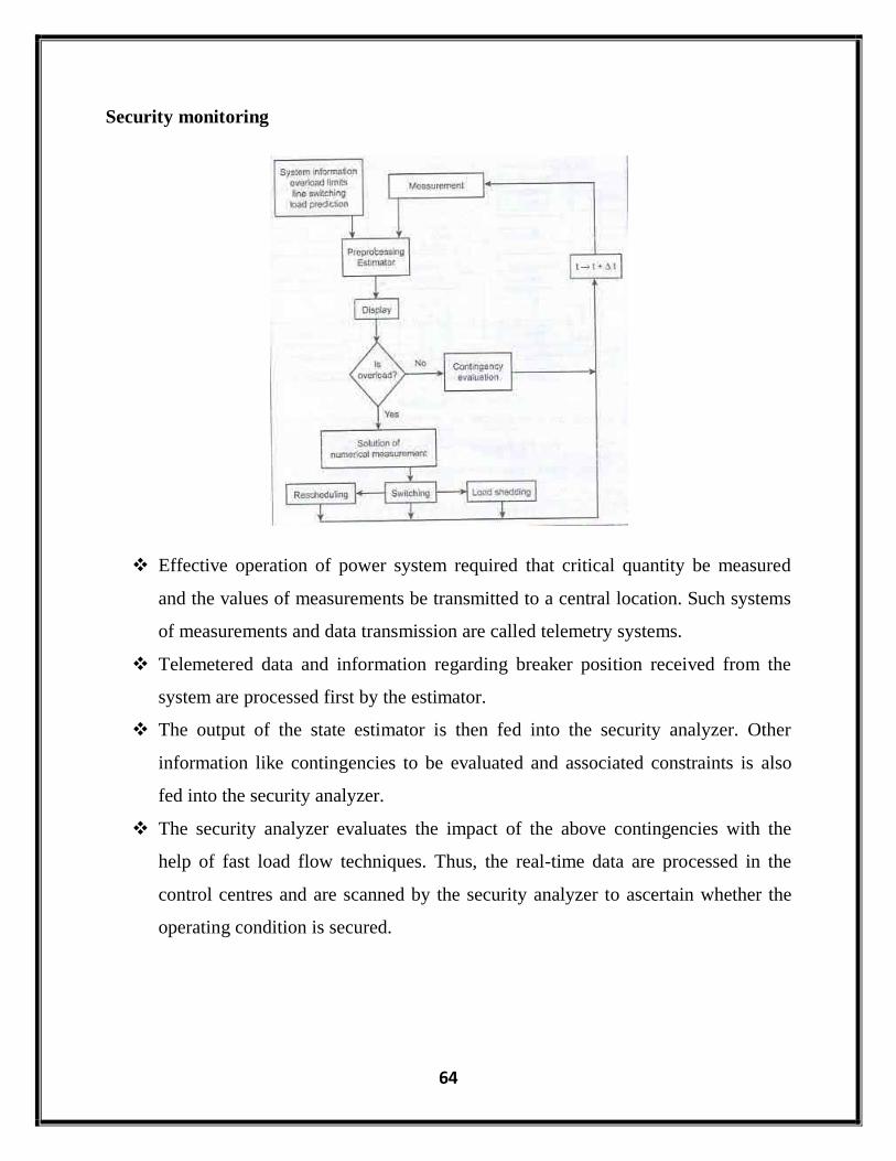
Security monitoring
Effective operation of power system required that critical quantity be measured
and the values of measurements be transmitted to a central location. Such systems
of measurements and data transmission are called telemetry systems.
Telemetered data and information regarding breaker position received from the
system are processed first by the estimator.
The output of the state estimator is then fed into the security analyzer. Other
information like contingencies to be evaluated and associated constraints is also
fed into the security analyzer.
The security analyzer evaluates the impact of the above contingencies with the
help of fast load flow techniques. Thus, the real-time data are processed in the
control centres and are scanned by the security analyzer to ascertain whether the
operating condition is secured.

65
The security monitoring functions are given below:
Function Function performed
Data acquisition
To process message from RTUs.
To check analog measurements against limits.
To check status values against normal value.
To send alarm conditions to alarm processor.
Alarm processor To send alarm messages.
To transmit messages according to priority.
Status processor To determine status of each substation for proper
connection
Reserve monitor To check generator MW output on all units against unit
limit.
State estimator
To determine system state variables.
To detect the presence of bad measured values.
To identify the location of bad measurements.
To initialize the network model for other programs.\
State estimator receives information from SCADA system and the network
topology and stores the status of the system (V and δ) in a central location called
database.

66
Power system application like power flow, optimal power flow, contingency
analysis and short circuit analysis are executed using the state of the system were
computed by state estimation
5.7 VARIOUS CONTROLS FOR SECURE OPERATION.
System Security for secure operation
System security involves practices designed to keep the system operating when
components fail. Systems security can be broken down into three major functions that are
carried out in an energy control centre:
System monitoring
Contingency analysis
Security-constrained optimal power flow
System monitoring
It provides the operators of the power system with pertinent up to data information
on the conditions of the power system. Effective operation of the system is required that
critical quantities are measured and the values of measurements are transmitted to a
central location. Such system of measurements and data transmission called telemetry
systems, have evolved to schemes that can monitor voltages, currents, power flows and
status of circuit breakers and switches in every substation in a power system transmission
network.
Contingency analysis
The results of this type of analysis allow system to be operated defensively. Many
of the problems that occur on a power system can cause serious trouble which is often the
case with cascading failures. In this analysis, certain programs are used that model
possible system and are used to study outage events and alarm the operators about any
potential overloads or out-of-time voltages.

67
Security-constrained optimal power flow
In this function, a contingency analysis is combined with an optimal power flow
which seeks to make changes to the optimal dispatch of generation, as well as other
adjustments, so that when a security analysis is run, no contingencies result in violations.
Other control for secure operation
State estimator:
To determine the best estimate of the state of the system using real time status and
measurements.
Power flow:
To calculate V, δ, power flows for the steady state condition.
Contingency analysis:
To determine the events which are harmful to the system by determining the states.
Optimal power flow:
Optimize a specified objective function by using controller action.
Security enhancement:
To alleviate an existing overload in the system by using corrective control actions.
Preventive action:
Before the occurrence of contingency event, preventive action has to be taken.
Bus load forecasting:
Forecast the load using real time measurements.
Transmission loss factors:
Calculate the impact of the transmission losses using incremental transmission loss (ITL).
Short circuit analysis:
Determine the fault current for different types of faults.

68
Factors affecting power system security
As a consequence of many widespread black-outs in interconnected power
systems, the priorities for operation of the modern power systems have evolved to the
following:
Operate the system in such a way that power is delivered reliably.
Within the constraints placed on the system operation by reliability
considerations, the system will be operated most economically.
Characteristics of the physical system (generation, transmission and
distribution systems and protection systems).
Any piece of equipment in the system can fail either due to internal causes or due to
external causes such as lightning stroke, object hitting transmission towers, or human
errors in setting relays. Thus, most power systems are designed to have sufficient
redundancy to withstand all major failure events.
Business structures of owning and operating entities.
The regulatory frame work.
Method of enhancing security
Impractical to achieve complete immunity to black-out.
Need to strike a balance between economy and security.
Good design and operating practices could significantly minimize the
occurrence and impact of widespread outages.
Reliability criteria.
Online security assessment.
Robust stability controls.
Real-time system monitoring and control.
Coordinated emergency controls.
Wide spread use of distributed generation.