syllabus ee6603 power system operation and control … fileee6603 power system operation and control...
TRANSCRIPT

REGULATION:2013 ACADEMIC YEAR:2018-2019
JIT-JEPPIAAR /EEE/Mrs.S.SARUMATHI/ IIIrdYr /SEM 06/EE6603/Power system Operation & Control/UNIT1-5/QB+ KEYS /VER 1.0
4.1
SYLLABUS
EE6603 POWER SYSTEM OPERATION AND CONTROL
L T P C
3 0 0 3
OBJECTIVES:
• To have an overview of power system operation and control. • To model power-frequency dynamics and to design power-frequency controller.
• To model reactive power-voltage interaction and the control actions to be
implemented for maintaining the voltage profile against varying system load.
• To study the economic operation of power system.
• To teach about SCADA and its application for real time operation and control of power
systems. UNIT I INTRODUCTION 9 An overview of power system operation and control - system load variation - load
characteristics - load curves and load-duration curve - load factor - diversity factor -
Importance of load forecasting and quadratic and exponential curve fitting techniques of
forecasting – plant level and system level controls . UNIT II REAL POWER - FREQUENCY CONTROL 9 Basics of speed governing mechanism and modeling - speed-load characteristics – load
sharing between two synchronous machines in parallel - control area concept - LFC control
of a single-area system - static and dynamic analysis of uncontrolled and controlled cases -
two-area system – modeling - static analysis of uncontrolled case - tie line with frequency
bias control - state variable model - integration of economic dispatch control with LFC. UNIT III REACTIVE POWER–VOLTAGE CONTROL 9 Generation and absorption of reactive power - basics of reactive power control - excitation
systems – modeling - static and dynamic analysis - stability compensation - methods of
voltage control: tap-changing transformer, SVC (TCR + TSC) and STATCOM – secondary
voltage control. UNIT IV UNIT COMMITMENT AND ECONOMIC DISPATCH 9 Formulation of economic dispatch problem – I/O cost characterization – incremental cost
curve - co-ordination equations without and with loss (No derivation of loss coefficients) -
solution by direct method and λ-iteration method - statement of unit commitment problem –
priority-list method - forward dynamic programming. UNIT V COMPUTER CONTROL OF POWER SYSTEMS 9 Need for computer control of power systems - concept of energy control centre - functions -
system monitoring - data acquisition and control - system hardware configuration – SCADA
and EMS functions - network topology - state estimation – WLSE - Contingency Analysis -
state transition diagram showing various state transitions and control strategies. TOTAL : 45 PERIODS
OUTCOMES:
Ability to understand and analyze power system operation, stability, control and protection.
TEXT BOOKS: 1. Olle.I.Elgerd, ‘Electric Energy Systems theory - An introduction’, Tata McGraw Hill
Education Pvt. Ltd., New Delhi, 34th reprint, 2010.

REGULATION:2013 ACADEMIC YEAR:2018-2019
JIT-JEPPIAAR /EEE/Mrs.S.SARUMATHI/ IIIrdYr /SEM 06/EE6603/Power system Operation & Control/UNIT1-5/QB+ KEYS /VER 1.0
4.2
2. Allen. J. Wood and Bruce F. Wollenberg, ‘Power Generation, Operation and Control’, John Wiley & Sons, Inc., 2003.
3. Abhijit Chakrabarti, Sunita Halder, ‘Power System Analysis Operation and Control’, PHI learning Pvt. Ltd., New Delhi, Third Edition, 2010.
REFERENCES:
1. 1. Nagrath I.J. and Kothari D.P., ‘Modern Power System Analysis’, Tata McGraw-Hill,
Fourth Edition, 2011. 2. Kundur P., ‘Power System Stability and Control, Tata McGraw Hill Education Pvt. Ltd.,
New Delhi, 10th reprint, 2010. 3. Hadi Saadat, ‘Power System Analysis’, Tata McGraw Hill Education Pvt. Ltd., New
Delhi, 21st reprint, 2010. 4. N.V.Ramana, “Power System Operation and Control,” Pearson, 2011. 5. C.A.Gross, “Power System Analysis,” Wiley India, 2011.

REGULATION:2013 ACADEMIC YEAR:2018-2019
JIT-JEPPIAAR /EEE/Mrs.S.SARUMATHI/ IIIrdYr /SEM 06/EE6603/Power system Operation & Control/UNIT1-5/QB+ KEYS /VER 1.0
4.3
Subject Code: EE6603 Year/Sem: III/06
Subject Name: Power System operation and control Subject Handler: Ms. S.Sarumathi
UNIT I – INTRODUCTION
An overview of power system operation and control - system load variation - load characteristics -
load curves and load-duration curve - load factor - diversity factor - Importance of load
forecasting and quadratic and exponential curve fitting techniques of forecasting – plant level and
system level controls .
PART *A
Q.No. Questions
1.
State the objective of power system control. BTL2
To maintain a continuous balance between electrical generation and varying load demand while
system frequency and voltage levels are maintained constant.
2.
State the effect of variable load in power system.(Nov/Dec 2012) BTL1
Due to variation in load there will be some effects on the power station. Some important effects
are
Need of additional equipment
Increase in production cost
3.
What is a load curve? (Nov 11,12)
The curve drawn between the variations of load on the power station with respect to time is
known as load curve.
4.
Define the term base load.
Base load is the load that has been drawn constantly throughout the time.
5.
Define load factor. (May 2012) BTL1
The ratio of average load to the maximum demand during a given period is known as load
factor.
=
6.
Differentiate load curve and load duration curve. (Nov 2014) BTL4
Load curve Load duration curve
Load curve is curve plotted between load and
time
When the load elements of the load curve are
arranged in the order of descending
magnitude.
This curve shows the variation of load on the
power station with respect to time
The curve obtained is a load duration curve.
7.
Classify different types of loads. BTL4
Lightning and heat loads
Induction motors
Electronic devices

REGULATION:2013 ACADEMIC YEAR:2018-2019
JIT-JEPPIAAR /EEE/Mrs.S.SARUMATHI/ IIIrdYr /SEM 06/EE6603/Power system Operation & Control/UNIT1-5/QB+ KEYS /VER 1.0
4.4
8.
Define diversity factor. (Nov 11,13,14) BTL1
The ratio of sum of individual maximum demand on the power station is known as diversity
factor.
=
9. What is spinning reserve? (Nov/Dec 2018)BTL1
The units that can be started within a short duration of time to meet the change in load when a
particular unit fails in the power system is called spinning reserve.
10.
Define the term average load or average demand. BTL1
The average of load occurring on the power station in a given period (day or month or year) is
known as average demand.
=
11.
What is the need for load forecasting? (Nov/Dec 2015,2018) BTL2
To meet out the future demand
Long term forecasting is required for preparing maintenance schedule of the generating
units, planning future expansion of the system
For day to day operation, short term load forecasting demand and for maintaining the
required spinning reserve.
Very short term load forecasting is used for generation and distribution That is economic
generation scheduling and load dispatching
Medium term load forecasting is needed for predicted monsoon acting and hydro
availability scheduling.
12. Define connected load. (Nov 2011) BTL1
The sum of continuous rating of all the equipment connected to supply system is known as
connected load.
13.
Define capacity factor. (Nov 2013) BTL1
=
Plant capacity factor is defined as the ratio of actual energy produced to the maximum possible
energy that could have been produced during a given period.
14.
Define plant use factor. (Nov 11,13)(May 14) BTL1
The ratio of units generated to the product of plant capacity and the number of hours for which
the plant was in operation.
15.
Define system level control. BTL1
System level control consists of
Secondary automatic load frequency control
Economic dispatch control
Unit commitment
Transmission system voltage control
System security control

REGULATION:2013 ACADEMIC YEAR:2018-2019
JIT-JEPPIAAR /EEE/Mrs.S.SARUMATHI/ IIIrdYr /SEM 06/EE6603/Power system Operation & Control/UNIT1-5/QB+ KEYS /VER 1.0
4.5
16. Define maximum demand. (Nov 2012) (May 2014) BTL1
It is the greatest demand of load on the power station during a given period is known as
maximum demand.
17.
Define demand factor. (Nov 2015) BTL1
Demand factor is defined as the ratio of maximum demand to connected load.
=
18.
What is the effect of load factor on the cost of generation? (May 2013) BTL4
Load factor is always less than 1 because average load is smaller than the maximum demand.
The load factor plays a vital role in determining the overall cost per unit generated. Higher the
load factor of the power station, lesser will be the cost per unit generated
It is because higher load factor means lesser maximum demand.
19.
State the plant level controls. BTL1
Prime mover control
Excitation control
20.
Define utilization factor. BTL1
It is the measure of the utility of the power plant capacity and is the ratio of maximum demand
to the rated capacity of the power plant. It is less than unity
=
21.
What are the advantages of computer control in power system? What are the types of
comcomputer control?
Optimal operation and control
Low maintenance and operating cost
High speed of operation
Fast network monitoring
Types of computer control
Supervisory control
Direct control
22.
What are brownouts? (May 2017) BTL1
A brownout is an intentional or unintentional drop in voltage in an electric power supply
system. International brownouts are used for load reduction in an emergency. The reduction
lasts for minutes or hours, as opposed to short term voltage sag or dip.
PART * B
1.
Explain the overview of power system operation and control and the role of computer in
the implementation with the help of block diagram. (Nov 2012,2014,2018) (13M) BTL4
Answer: Page 1.33- M.Jeraldin Ahila
Definition: (2M)
Function of an electric power system to convert energy from one of naturally-available form –
electric form-transport point of consumption.
Power system operation: (3M)
Power system have the responsibility to ensure supply of good quality power when
customer demands.
Power system should able to supply ever changing load demand.
Power System Control: (3M)
Problems of dynamic and transient stability, steady state stability, voltage and frequency

REGULATION:2013 ACADEMIC YEAR:2018-2019
JIT-JEPPIAAR /EEE/Mrs.S.SARUMATHI/ IIIrdYr /SEM 06/EE6603/Power system Operation & Control/UNIT1-5/QB+ KEYS /VER 1.0
4.6
regulation, power optimization need to properly analyze.
Block diagram: (3M)
Role of computer: (2M)
Digital control by computers-enables-processing of large number of different data and
constraints involved in power system operation.
2.
Describe briefly about plant level and system level controls. (May 2013) (13M) BTL4
Answer: Page 1.34- M.Jeraldin Ahila
Diagram: (4M)
Factors: (2M)
Quality of power determined by system frequency-magnitudes of bus voltages
Plant level control: (4M)
Governor control-prime mover control-speed regulation –control of energy supply system –
boiler pressure –temperature
Automatic voltage regulator-regulate generator voltage and relative power output-terminal
voltage varies-excitation control-maintains the terminal voltage.
System level control: (3M)
Load frequency control
Economic dispatch control
System voltage control
3.
Compare various stochastical methods of load forecasting. (May 2015) (13M) BTL4
Answer: Page 14-Notes
Time series approach: (4M)
Auto-Regressive model
Auto-Regressive Moving Average
Kalman Filtering approach: (4M)
Short term load forecasting using periodic load model
Innovation model approach: (5M)
Estimating model order
Estimating gain vector
4.
Consider an inductive load of type Z =R+jX. By how much percentage the real load drop,
if the voltage is reduced by 5%.How would 2% drop in frequency affect the real load, if
the load power factor is 0.8. Derive the relations used.(May 2016) (13M) BTL4
Answer: Page 1.11- M.Jeraldin Ahila
Real load drop: (7M)
Admittance Y =
S = P+jQ
P =
Q=
Drop in frequency: (6M)
2% frequency drop results in 1.44% load increase

REGULATION:2013 ACADEMIC YEAR:2018-2019
JIT-JEPPIAAR /EEE/Mrs.S.SARUMATHI/ IIIrdYr /SEM 06/EE6603/Power system Operation & Control/UNIT1-5/QB+ KEYS /VER 1.0
4.7
5.
A power station has to meet the following demand:
Group A: 200 KW between 8 A.M and 6 P.M
Group B: 100 KW between 6 A.M and 10 A.M.
Group C: 50 KW between 6 A.M and 10 A.M
Group D:100 KW between 10 A.M and 6 P.M and then between 6 P.M and 6 A.M. plot the
daily load curve and determine
i. Diversity factor
ii. Units generated per day
iii. Load factor (Nov 2014)(13M) BTL3
Answer: Page 1.24- M.Jeraldin Ahila
Load curve: (3M)
Maximum demand = 350 KW (2M)
Diversity factor: (2M)
=
=
Units generated: (3M)
Units generated per day = 4600 Kwhr
Load factor: (3M)
Load factor = 54.76%
6.
(i)Briefly describe the importance of load forecasting and explain the method of least
square fit forecasting the base load. (May 2012) (8M) BTL4
Answer: Page 14-Notes
Importance: (3M)
Deregulated economy
Generation
Load switching
Contract evaluation
Infrastructure development
Least Square fit: (5M)
(ii) Explain the information obtained from load curves and load duration curves.
(May 2012) (5M) BTL4
Answer: Page 1.16- M.Jeraldin Ahila
Load curves: (2M)
Variation of load on power station
Maximum and minimum values of daily load.
Annual maximum and minimum value of load
Average annual load on the station
Load duration curve: (3M)
Maximum demand and minimum demand can be observed.
Units generated on that period can be obtained.
REGULATION:2013 ACADEMIC YEAR:2018-2019
JIT-JEPPIAAR /EEE/Mrs.S.SARUMATHI/ IIIrdYr /SEM 06/EE6603/Power system Operation & Control/UNIT1-5/QB+ KEYS /VER 1.0
4.8
7.
Explain the important objectives of power system and various control strategies during its
operation. (Nov 2012) (13M) BTL2
Answer: Page 1.2 and 1.33- M.Jeraldin Ahila
Objective of power system: (4M)
To maintain continuous balance between electrical generation and varying load demand.
System frequency and voltage levels are maintained constant.
Control strategies: (5M)
Plant level control-Governor control and automatic voltage regulator control.
System level control-Load frequency control-Economic dispatch control-System voltage control
Diagram: (4M)
8.
(i)What is meant by chronological load curve? Give the information obtained from load
curves. (May 2013) (8M) BTL4 Answer: Page 1.16- M.Jeraldin Ahila
Chronological load curve: (4M)
The curve drawn between the variations of load on the power station with respect to time is
known as load curve.
Information from Load curves: (4M)
Variation of load on power station
Maximum and minimum values of daily load.
Annual maximum and minimum value of load
Average annual load on the station (ii) A power plant supplies the following loads with maximum demand as below:
Type of load Individual maximum demand
Industries 100
Domestic 15
Commercial 12
Agriculture 20
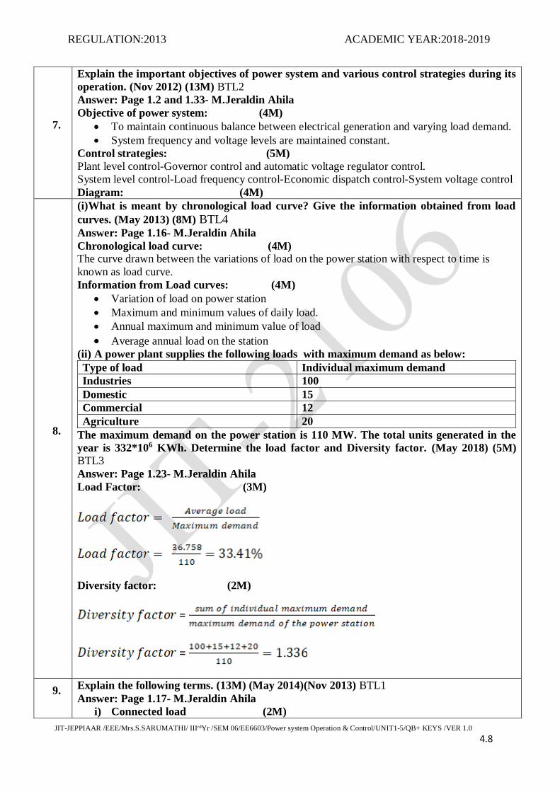
The maximum demand on the power station is 110 MW. The total units generated in the
year is 332*106 KWh. Determine the load factor and Diversity factor. (May 2018) (5M)
BTL3
Answer: Page 1.23- M.Jeraldin Ahila
Load Factor: (3M)
Diversity factor: (2M)
=
=
9. Explain the following terms. (13M) (May 2014)(Nov 2013) BTL1
Answer: Page 1.17- M.Jeraldin Ahila
i) Connected load (2M)

REGULATION:2013 ACADEMIC YEAR:2018-2019
JIT-JEPPIAAR /EEE/Mrs.S.SARUMATHI/ IIIrdYr /SEM 06/EE6603/Power system Operation & Control/UNIT1-5/QB+ KEYS /VER 1.0
4.9
The sum of continuous rating of all the equipment connected to supply system is known as
connected load.
ii) Load factor (2M)
The ratio of average load to the maximum demand during a given period is known as load
factor.
=
iii) Diversity factor (3M)
=
iv) Average demand (2M)
=
v) Hot reserve (2M)
Hot reserve-reserve generating capacity which not in operation-but not in service.
vi) Cold reserve (2M)
Cold reserve –reserve generating capacity-available for service-but not in operation
10.
A power supply is having the following loads:
Type of load Maximum demand
(KW)
Diversity factor Demand factor
Domestic 10,000 1.2 0.8
Commercial 30,000 1.3 0.9
Industrial 50,000 1.35 0.95
If overall system diversity factor is 1.5, determine
Maximum demand and Connected load of each type (May 2014) (13M) BTL3
Answer: Page 1.25- M.Jeraldin Ahila
Total Maximum Demand: (3M)
Total maximum demand of load = 10000+30000+50000 = 90000 Kw
Maximum demand: (3M)
=
Connected load of each type: (7M)
PART*C
1.
A generating station has a maximum demand of 50,000 KW. Calculate the cost per unit
generated from the following data. (Nov 2011) (15M) BTL3
Capital cost = Rs 95*106
Annual load factor = 40%
Annual cost of fuel and oil = Rs 9*106

REGULATION:2013 ACADEMIC YEAR:2018-2019
JIT-JEPPIAAR /EEE/Mrs.S.SARUMATHI/ IIIrdYr /SEM 06/EE6603/Power system Operation & Control/UNIT1-5/QB+ KEYS /VER 1.0
4.10
Taxes wages and salaries etc., = Rs 7.5*106
Interest and depreciation = 12 %
Answer: Page S.53- M.Jeraldin Ahila
Cost per unit generated: (4M)
Total annual running charges = (9*106)+(7.5*106) = 16.5*106
Fixed charge: (3M)
Annual fixed charges = 12% of capital cost = Rs 11.4*106
Units generated per annum: (4M)
Maximum demand*Annual load factor*Hours in a year
50,000*0.4*8760 = 17.52*107 Kwh
Cost per unit generated: (4M)
Cost per unit generated =
2.
A generating station has a maximum demand of 20 MW, a load factor of 60%, plant
capacity factor of 48% and a plant use factor of 80%
Find the
(i)Daily energy produced
(ii)Reserve capacity of the plant
(iii)Maximum energy that could be produced daily if the plant were running all the time
(iv)Maximum energy that could be produced if the plant when running (according to
operating schedule) were fully loaded. (Nov 2011) (15M) BTL3
Answer: Page 1.26- M.Jeraldin Ahila
Load factor: (3M)
Plant capacity factor =
Average load: (4M)
Average load = 15 KW
Installed capacity: (3M)
Installed capacity =
Reserve capacity: (5M)
Energy produced per day = 15*24 = 360 Kw/day
Reserve capacity = plant capacity-maximum demand=5 Kw
3.
A generating station has the following daily load cycle.
Time (hrs) 0-6 6-10 10-12 12-16 16-20 20-24
Load (MW) 20 25 30 25 35 20
Draw the load curves and calculate,
Maximum demand
Units generated per day
Average load

REGULATION:2013 ACADEMIC YEAR:2018-2019
JIT-JEPPIAAR /EEE/Mrs.S.SARUMATHI/ IIIrdYr /SEM 06/EE6603/Power system Operation & Control/UNIT1-5/QB+ KEYS /VER 1.0
4.11
Load factor. (Nov 2013) (Nov 2015,2018) (15M) BTL3
Answer: Page 1.22- M.Jeraldin Ahila
Load curve: (4M)
Maximum demand: (3M)
Maximum demand = 35 MW
Units generated per day: (3M)
Units generated per day = Area under the load curve in Kwhr
Area under the load curve in Kwhr = (6*20+4*25+2*30+4*25+4*35+4*20) = 600*103 kwhr
Average load: (2M)
Load factor: (3M)

REGULATION:2013 ACADEMIC YEAR:2018-2019
JIT-JEPPIAAR /EEE/Mrs.S.SARUMATHI/ IIIrdYr /SEM 06/EE6603/Power System Operation & Control/UNIT1-5/QB+ KEYS /VER 1.0 4.12
UNIT II – REAL POWER - FREQUENCY CONTROL
Basics of speed governing mechanism and modeling - speed-load characteristics – load sharing
between two synchronous machines in parallel - control area concept - LFC control of a single-
area system - static and dynamic analysis of uncontrolled and controlled cases - two-area system –
modeling - static analysis of uncontrolled case - tie line with frequency bias control - state variable
model - integration of economic dispatch control with LFC.
PART *A
Q.No. Questions
1.
State the function of load frequency control. (May 2013) (Nov 2013) BTL1
The function of load frequency control is to change the control valve or gate opening of the
prime movers as a function of load variation in order to hold system frequency constant.
2.
How is the real power in power system controlled? (May 2012) BTL4
The real power in a power system is controlled by controlling the driving torques of individual
turbine of the system.
3.
What is meant by load frequency control? (Nov/Dec 2007) (May 2012) BTL1
In inter connected system with two or more independently controlled areas, in addition to
control of frequency, generation within each area has to be controlled to maintain scheduled
power interchange.
4.
State any two necessities to put alternators in parallel. (May 2014) BTL2
Alternators may be put in parallel become of the following reason
Local or regional power use may exceeds the power of a single available generation
Parallel alternators allow one or more units to be shut down for scheduled or emergency
maintenance while the load is being supplied with power.
5.
Give two conditions for proper synchronizing of alternators. (Nov 2011) BTL1
The condition for proper synchronization are
The terminal voltage of the incoming machine must be exactly equal to that of the others
or the bus bars connecting them.
The speed of the incoming machine must be such that its frequency equals to the bus bar
frequency.
6.
Differentiate static &dynamic response of an ALFC loop. (Nov 2016) BTL4
Static response of an ALFC loop will inform response of ALFC loop will inform about
frequency accuracy. Whereas the dynamic response of ALFC loop will inform about the stability
of the loop.
7.
What is meant by control area? (Nov 14,15,16,18) BTL1
It is possible to divide an extended power system (say, national grid) into sub areas in which the
generators are tightly coupled together so as to form a coherent group, all the generators respond
in union to changes in load or speed changer settings. Such a coherent area is called a control
area in which the frequency is assumed to be the same throughout in static as well as dynamic
conditions.

REGULATION:2013 ACADEMIC YEAR:2018-2019
JIT-JEPPIAAR /EEE/Mrs.S.SARUMATHI/ IIIrdYr /SEM 06/EE6603/Power System Operation & Control/UNIT1-5/QB+ KEYS /VER 1.0 4.13
8.
State the assumptions made in dynamic response of uncontrolled case. (May 2014) BTL1
Neglect the turbine dynamics
The speed changer action is instantaneous.
9.
State the principle of tie line bias control. (April/June 2016) BTL1
The control strategy is termed as tie line bias control and is biased upon the principle that all
operating pool members must contribute their share to the frequency control in addition to
taking care of their own net incharge.
10.
Define area control error. (May/June 2016) BTL1
Area control error is the change in frequency which when used in integral control loop forced
the steady state frequency error to zero.
=
=
b = area frequency bias
= change in tie line power
= change in frequency
11.
Compare the function of Speed Governor and Speed changer in a speed governing system
of a turbine-generator set. (April/May 08) BTL4
Speed Governor Speed changer
Purely mechanical speed sensitive device
coupled directly to the hydraulic amplifier the
control valve operating via the linkage
mechanism.
The speed changer makes it possible to
restore the frequency to the initial value after
operation of the speed governors having the
steady state characteristics
12.
Define inertia constant. BTL1
Inertia constant H is defined as the ratio of kinetic energy stored in the rotor to the MVA rating
of the generator
13.
State the purpose of a speed changer. BTL4
The speed changer makes it possible to restore the frequency to the initial value after operation
of the speed governors having steady state characteristics.
14.
State the purpose of fly ball speed governor. BTL4
Fly ball speed governor is purely mechanical speed sensitive device coupled directly to the
hydraulic amplifier which adjusts the control valve opening via the linkage mechanism.
15.
How can the flow of high pressure steam controlled? BTL2
By controlled the position of the control valve or gate control can be exerted over the flow of
high pressure steam through the turbine.
16.
Write the tie line power deviation equation in terms of frequency. BTL4
= 2π [s

REGULATION:2013 ACADEMIC YEAR:2018-2019
JIT-JEPPIAAR /EEE/Mrs.S.SARUMATHI/ IIIrdYr /SEM 06/EE6603/Power System Operation & Control/UNIT1-5/QB+ KEYS /VER 1.0 4.14
17.
Define AFRC. BTL1
The system performance in terms of how the change in power effects the change in frequency is
evaluated through AFRC.
18. State the basic role of ALFC. BTL2
The basic role of ALFC is to maintain desired megawatt output of the generator unit and assist
in controlling the frequency of the larger inter-connection.
19.
State the need for integral controller in ALFC. (April/May 2017) BTL4
Speed changer setting can be adjusted automatically by monitoring the dynamic
frequency changes with changes in load and the synchronous clock run on time, but not
without error during transient period.
For this purpose a signal from is fed through an integrator to the speed changer
The integral controller actuates the load reference point until the frequency deviation
becomes zero.
20.
Define stiffness of the interconnected system. BTL1
= synchronizing power coefficient or electric stiffness
Synchronizing power coefficient or electric stiffness is defined as the differential power
increase obtained per differential power angle increase.
21.
Define per unit droop. BTL1
The per unit droop or speed regulation R of the generating unit is defined as the magnitude of
change in steady state speed, expressed in p.u of rated speed, when the output of unit gradullay
reduced from 1.0 p.u rated power to zero.
= p.u.
= Frequency at no load,Hz.
Frequency at rated megawatt output,
22.
State the control objective of two area load frequency control. (Nov 2014) BTL2
During normal operating condition, each control area should have the capacity to meet its own
load demand with its spinning generator.
During emergency condition, the energy can be drawn from the spinning reserve of the
neighboring area immediately due to the outage of generating unit.
To regulate the frequency of each area and to simultaneously regulate the tie line power as per
the inter area power contracts.
23. Brief the application of secondary ALFC loop in power system networks. (May 2015)
(Nov 2018)BTL2
A frequency sensor senses bus bar frequency and compares with the tie line power frequency.

REGULATION:2013 ACADEMIC YEAR:2018-2019
JIT-JEPPIAAR /EEE/Mrs.S.SARUMATHI/ IIIrdYr /SEM 06/EE6603/Power System Operation & Control/UNIT1-5/QB+ KEYS /VER 1.0 4.15
The speed changer gives the response speed to the governor and to maintain the rated speed.
The integral controller is used to reduce the steady state frequency error.
24.
Find the open loop gain of an automatic voltage regulator loop if the static error does not
exceed 2%. (May 2015) BTL4
K>((100/
K>((100/
K>49
Thus the open loop gain of the AVR loop is greater than 49, then the static error will be within
2%.
25.
What is the advantage of AVR loop over ALFC? (Nov 2015) BTL2
AVR loop is much faster than ALFC loop and therefore there is a tendency, for the VR
dynamics to settle down before they can make themselves felt in the slower load frequency
control channel.
26.
Distinguish between primary and secondary feedback loops in load frequency control.
(May 2018) BTL2
Primary ALFC Secondary ALFC
The circuit primarily controls the steam valve
leading to the turbine.
The circuit involves a frequency sensor that
senses the frequency of the bus bar and
compares it with tie line power frequencies in
the signal mixer
The speed signal is compared with reference
speed, governor whose main activity is to
control the speed of the steam by closing and
opening of the control valve.
The output is an Area control Error which
sent to speed changer through integrator.
The speed changer gives the reference speed
to the governor.
PART*B
1.
Draw the block diagram of uncontrolled two area load frequency control system and
explain the salient features under static conditions. (Nov 2011)(May 2013) (13M) BTL4
Answer: Page 2.61- M.Jeraldin Ahila
Block diagram: (6M)
Static analysis: (7M)
, stat =
, stat =
2.
How is speed governor mechanism modeled? Explain its operation with the speed-load
characteristics. (Nov 2011) (13M) BTL4
What are the components of speed governor system of an alternator? Derive the
mathematical model of speed governor system with the aid of block diagram.
(May 2012) (Nov 2013)

REGULATION:2013 ACADEMIC YEAR:2018-2019
JIT-JEPPIAAR /EEE/Mrs.S.SARUMATHI/ IIIrdYr /SEM 06/EE6603/Power System Operation & Control/UNIT1-5/QB+ KEYS /VER 1.0 4.16
Derive the modeling of fundamental speed governing system.(Nov 2015)
With the block diagram of speed governing system, explain the Automatic load
frequency control. Also derive necessary equations. (May 2015)
Answer: Page 2.3- M.Jeraldin Ahila
Diagram: (4M)
Explanation: (5M)
Flyball speed governor
Speed changer
Hydraulic amplifier
Linkage mechanism
Speed load characteristics: (4M)
Per unit droop or speed regulation of the generating unit defined as the magnitude of change
in steady state speed expressed in p.u of rated speed when the output of the unit is gradually
reduced from 1.0 p.u rated power to zero.
3.
Explain the dynamic response of single area load frequency control. Also discuss the effect
of P-I controller on single area load frequency control. (May 2012) (13M) BTL4
Answer: Page 2.47- M.Jeraldin Ahila
Definition: (2M)
Dynamic response of loop will inform about tracking ability and stability of the loop
Diagram: (4M)
Load frequency: (4M)
Integral value: (3M)
=
=
4.
With a neat block diagram, explain the single area load frequency control system.
(Nov 2012,2014) (13M) BTL4
Answer: Page 2.27- M.Jeraldin Ahila
Block diagram: (4M)
Frequency function: (4M)
Final value theorem: (2M)
Steady state response: (3M)

REGULATION:2013 ACADEMIC YEAR:2018-2019
JIT-JEPPIAAR /EEE/Mrs.S.SARUMATHI/ IIIrdYr /SEM 06/EE6603/Power System Operation & Control/UNIT1-5/QB+ KEYS /VER 1.0 4.17
=
β= area frequency response coefficient
5.
(i)Discuss the integration of economic dispatch control with automatic generation control.
(Nov 2012) (8M) BTL4
Answer: Page 6.11- M.Jeraldin Ahila
Cost function: (2M)
Set of real generation variables must be selected that minimize the cost function.
Equality constraints: (2M)
H( ,
Inequality constraints: (4M)
(ii) List the advantages of Multiarea operation. (5M) BTL1
Answer: Page 2.56- M.Jeraldin Ahila
Under normal operating condition each control area should have the capacity to meet its
own lead from its own spinning generator.
Under emergency condition, the energy can drawn from the spinning reserves of all
neighboring areas immediately due to sudden loss of generating unit.
6.
(i)Derive an expression for load sharing between two alternators. What are the effects of
fuel supply and change of excitation? (Nov 2012) (8M) BTL4
Answer: Page 2.12- M.Jeraldin Ahila
Speed load characteristics: (2M)
Per unit droop or speed regulation of the generating unit defined as the magnitude of change in
steady state speed expressed in p.u of rated speed when the output of the unit is gradually
reduced from 1.0 p.u rated power to zero.
= p.u.
Slope: (2M)
Regulation (slope) =
Change in output: (2M)
Parallel operation: (2M)
(ii) The two system connected by a tie line describe the following characteristics

REGULATION:2013 ACADEMIC YEAR:2018-2019
JIT-JEPPIAAR /EEE/Mrs.S.SARUMATHI/ IIIrdYr /SEM 06/EE6603/Power System Operation & Control/UNIT1-5/QB+ KEYS /VER 1.0 4.18
Area 1 Area 2
R = 0.01 pu R = 0.02 pu
D =0.8 pu D =1.0 pu
Base MVA =500 Base MVA = 500
A load change of 100 MW (0.2 pu) occurs in area 1. What is the new steady state frequency
what is the change in tie flow? Assume both area were at nominal frequency?
(April/May 2018)(5M) BTL3
Answer: Page 2.66- M.Jeraldin Ahila
Static frequency: (2M)
Change in tie flow: (3M)
7.
(i)Develop a schematic of speed governing system and explain its operation.
(May 2013,2018) (8M) BTL6
Answer: Page 2.2- M.Jeraldin Ahila
Schematic diagram: (2M)
Explanation: (2M)
Flyball speed governor
Speed changer
Hydraulic amplifier
Linkage mechanism
Operation: (4M)
As load increases the speed of the turbine decreases.
Speed changer gives raise command and flyball moves outwards and point B moves
downwards.
D moves upwards and high pressure oil enters to the pilot valve and press the main piston
downwards and maintains constant frequency.
(ii)Analyze the governor-Speed drop characteristics, the basics of load sharing between
two synchronous machines in parallel. (May 2018) (5M) BTL3
Answer: Page 2.12- M.Jeraldin Ahila
Power output-Speed characteristics: (2M)
Per unit droop: (1M)
Per unit droop or speed regulation defined as magnitude of change in steady state speed when
output of unit gradually reduced from 1.0 p.u rated power to zero.
Change in output: (2M)
8.
Develop the state variable model of a two area system and state the advantages of the
model. (May 2014) (13M) BTL4
Answer: Page 2.75- M.Jeraldin Ahila
Definition: (2M)
Optimum Linear Regulator design results in a controller that minimizes both transient variable
oscillations and control effects.
REGULATION:2013 ACADEMIC YEAR:2018-2019
JIT-JEPPIAAR /EEE/Mrs.S.SARUMATHI/ IIIrdYr /SEM 06/EE6603/Power System Operation & Control/UNIT1-5/QB+ KEYS /VER 1.0 4.19
Block Diagram: (3M)
State variable: (3M)
X = =
Static variable form: (2M)
= + G + P
Linear state model: (1M)
Advantages: (2M)
9.
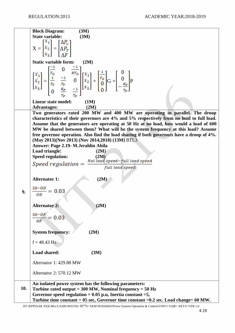
Two generators rated 200 MW and 400 MW are operating in parallel. The droop
characteristics of their governors are 4% and 5% respectively from no load to full load.
Assume that the generators are operating at 50 Hz at no load, how would a load of 600
MW be shared between them? What will be the system frequency at this load? Assume
free governor operation. Also find the load sharing if both governors have a droop of 4%.
(May 2013)(Nov 2013) (Nov 2014,2018) (13M) BTL3
Answer: Page 2.19- M.Jeraldin Ahila
Load triangle: (2M)
Speed regulation: (2M)
Alternator 1: (2M)
Alternator 2: (2M)
System frequency: (2M)
f = 48.43 Hz
Load shared: (3M)
Alternator 1: 429.88 MW
Alternator 2: 570.12 MW
10. An isolated power system has the following parameters:
Turbine rated output = 300 MW, Nominal frequency = 50 Hz
Governor speed regulation = 0.05 p.u, Inertia constant =5,
Turbine time constant = 05 sec, Governor time constant =0.2 sec. Load change= 60 MW.

REGULATION:2013 ACADEMIC YEAR:2018-2019
JIT-JEPPIAAR /EEE/Mrs.S.SARUMATHI/ IIIrdYr /SEM 06/EE6603/Power System Operation & Control/UNIT1-5/QB+ KEYS /VER 1.0 4.20
The load varies by 0.8% for a 1% change in frequency. Determine the steady state
frequency deviation in Hz. (May 2014) (13M) BTL3
Answer: Page 2.54- M.Jeraldin Ahila
Change in power demand: (3M)
Change in frequency: (3M)
(-
Block diagram: (3M)
Step Response: (1M)
Steady state frequency deviation: (3M)
PART*C
1.
A sub grid has total rated capacity 2500 MW. It encounters a load increase of 50 MW if
the normal operating load is 1000 MW. Assume inertia constant (H) to be 5 sec and
regulation of generator in the system as 2 Hz/p.u MW. Find
ALFC loop parameters
Static frequency drop
Transient response of ALFC loop
Assume load frequency to be linear. (May 2015) (15M) BTL3
Answer: Page 2.64- M.Jeraldin Ahila
ALFC loop parameters : (5M)
d =
= = 50 Hz/ p.u MW
= = 10 sec
Static frequency drop: (5M)

REGULATION:2013 ACADEMIC YEAR:2018-2019
JIT-JEPPIAAR /EEE/Mrs.S.SARUMATHI/ IIIrdYr /SEM 06/EE6603/Power System Operation & Control/UNIT1-5/QB+ KEYS /VER 1.0 4.21
=
Transient response: (5M)
= -α [1-ϵ Hz
= -0.03846 (1-
2.
A two area power system has two identical areas with parameters and operating conditions
Rated capacity of the area =1500 MW
Nominal operating load = 750 MW
Nominal frequency = 50 HZ
Inertia constant of the area = 5s
Speed regulation = 3%
Damping coefficient = 1%
Governor time constant = 0.06s
Turbine time constant = 0.25s
A load increase M1 = 30 MW occurs in area 1.
Determine change in frequency and compare the change in frequency obtained in single
area and comment on the support. (Nov 2015) (15M) BTL3
Answer: Page 2.63- M.Jeraldin Ahila
Change in frequency: (5M)
R = 1.5 Hz/p.u MW
β Value: (5M)
B+
β=0.6766 p.u Mw/Hz
: (5M)
3.
Draw the transfer function block diagram for a single area system provided with static
analysis of uncontrolled and controlled case. (Nov 2018) (15M) BTL3
Answer: Page 2.28- M.Jeraldin Ahila
Block Diagram: (5M)
Static Analysis: (5M)

REGULATION:2013 ACADEMIC YEAR:2018-2019
JIT-JEPPIAAR /EEE/Mrs.S.SARUMATHI/ IIIrdYr /SEM 06/EE6603/Power System Operation & Control/UNIT1-5/QB+ KEYS /VER 1.0 4.22
Step change
Final value theorem
Static Analysis (Controlled Case): (5M)
Step change
Final value theorem

REGULATION:2013 ACADEMIC YEAR:2018-2019
JIT-JEPPIAAR /EEE/Mrs.S.SARUMATHI/ IIIrdYr /SEM 06/EE6603/Power System Operation & Control/UNIT1-5/QB+ KEYS /VER 1.0 4.23
UNIT III – REACTIVE POWER–VOLTAGE CONTROL
Generation and absorption of reactive power - basics of reactive power control - excitation systems
– modeling - static and dynamic analysis - stability compensation - methods of voltage control: tap-
changing transformer, SVC (TCR + TSC) and STATCOM – secondary voltage control.
PART *A
Q.No. Questions
1.
State the function of AVR. (May 2013) BTL1
The function of AVR (Automatic Voltage Regulator is to regulate the output of generator
voltage and thereby regulate the reactive power flow.
2.
List the various functions of excitation systems. (Nov 2013) BTL2
The various functions of excitation systems are
The DC excitation system utilizes DC generator as a source of excitation power and provides
current to the rotor of the alternator through slip rings.
The main function of excitation system is to provide dc current to the field of the field of the
generator. The AC signal is rectified using the controlled or uncontrolled rectifier and supplied
to the field of generator
3.
State the difference between P-F and Q-V control. (May 2012) BTL4
Static changes in reactive power affects essentially only the magnitude of bus voltage, leaving
the phase of bus voltage unaffected. Therefore reactive power is directly proportional to bus
voltage V (Q α V)
Static change in real power will affect only the phase angle of the bus voltage leaving the
magnitude of the bus voltage unaffected. Therefore real power is proportional to the phase angle
of bus voltage. (P α δ )
4.
State the relation between voltage, power and reactive power at a node. (Nov 2014) BTL3
The system Voltage V at a node is a function of real and reactive power.
V = f(P,Q)
(E-2V)/R
(E-2V)/X
5.
List the functional elements of excitation system. BTL1
Exciter
Regulator
Terminal voltage transducer
Load compensator
Power system stabilizer
Limiters and protective circuits
6.
Define exciter. BTL1
Exciter is a device or combination of devices which supplies the magnetizing current to generate
the working flux.
The purpose of exciter is to supply the excitation DC voltages to the fixed poles of generator.

REGULATION:2013 ACADEMIC YEAR:2018-2019
JIT-JEPPIAAR /EEE/Mrs.S.SARUMATHI/ IIIrdYr /SEM 06/EE6603/Power System Operation & Control/UNIT1-5/QB+ KEYS /VER 1.0 4.24
Rotary exciter is an additional small generator mounted on the shaft.
7.
Define stability compensation. (Nov 2015 ) BTL1
In order to get static accuracy, high loop gain is needed. But this high loop gain causes
undesirable dynamic response, possibly instability. The stability compensation improves the
dynamic characteristics without offering the static loop gain. The stability compensation will
damp out the oscillations in the system.
8.
State the advantages of switching capacitors in voltage control. (Nov 2014,2018) BTL2
Transient free switching is ensured
Damping of energizing transients
Harmonics reduction
The system voltage can be maintained with the desired range.
9.
Distinguish between rotor angle stability and voltage stability. (May 2015) BTL2
Rotor angle stability voltage stability
Steady increase in generator rotor angle
creates lack of synchronizing torque in turn
rotor angle instability.
The system enters into state of voltage
instability when an increased demand in load
or a change in the system condition causes
progressive decrease in voltage.
10.
List the merits of synchronous compensator. BTL4
The system can operate at all load conditions
Smooth variation of reactive as compared to step by step variation in static
compensators.
Production of reactive power is not affected by system voltage
11.
State the different types of reactive power compensation. (Nov 2012) BTL4
Different types of reactive power compensation are
Variable Impedance-Inductor and capacitor
Switching converters-SVC,STATCOM and TCSC
12.
Define Booster transformer. (Nov 2012) BTL1
Booster transformer is a compensation device which is installed to increase the voltage in the
electric circuit. The booster transformer can be brought into the electric circuit by means of relay
operation.
13.
Comment on the use of series capacitors in transmission lines. (April/May 2017) BTL4
It is connected in series to compensate the inductive reactance of the line.
This reduces the transfer reactance between the buses to which the line is connected.
It increases the maximum power that can be transmitted and reduces reactive power loss.
The reactive power produced by the series capacitor increases with increase in power
transfer.
14.
Define exciter ceiling voltage. (April/May 2017) BTL1
Exciter ceiling voltage is the maximum voltage that may be attained by an exciter under specific
conditions.
15.
What is SVC? (May/June 2016) BTL1
Static VAR compensators are located in receiving substations and distribution system for
smooth and stepless variation of compensation of reactive power injected into line by shunt
capacitor and shunt reactors.
16.
How are voltage and reactive power interrelated? (May/June 2016) BTL4
=

REGULATION:2013 ACADEMIC YEAR:2018-2019
JIT-JEPPIAAR /EEE/Mrs.S.SARUMATHI/ IIIrdYr /SEM 06/EE6603/Power System Operation & Control/UNIT1-5/QB+ KEYS /VER 1.0 4.25
R-Resistance of line is neglected
=
The flow of reactive power is determined by the difference between sending end and receiving
end voltage.
17.
List the various components in AVR loop. BTL1
Exciter
Comparator
Amplifier
Rectifier
Synchronous generator
18.
State whether changes in AVR loop will be reflected in ALFC loop. BTL4
Control actions in the AVR loop affect the magnitude of the generator emf E
As the internal emf determines the magnitude of the real power, changes in the AVR
loop must be felt in the ALFC loop.
19.
State the main objective of Reactive power and voltage control in power systems.
(May 2018) BTL1
The terminal voltage of all equipment in the power system are within acceptable limits,
both utility equipment and customer equipment are designed to operate at certain voltage
rating
The system reactive power flow is maintained so as to reduce losses to minimum in
practice.
20.
State the effects of AVR loop. BTL3
AVR must regulate the terminal voltage V within required static accuracy limit.
It must have sufficient speed response.
It must be stable.
21.
Outline the role of synchronous generators adopted for generation and absorption of
reactive power. (May 2018)BTL4
The tendency of synchronous generators can generate or absorb reactive power depending on the
excitation. When over excited the generators they supply reactive power and when under excited
they absorb reactive power.
22.
What are the different types of static VAR compensator? (Nov 2018) BTL1
Saturated reactors
Thyristor controlled reactors
Thyristor switched capacitors
Thyristor switched reactors
Thyristor controlled transformers
Fixedd capacitor and thyristor controlled reactors
PART*B
1.
Develop the block diagram of AVR and obtain its transfer function and explain its static
and dynamic response. (May 2017) (Nov 2018) (13M) BTL4
Explain with neat block diagram the excitation system and its modeling with relevant
transfer functions. (May 2018)
Answer: Page 3.4- M.Jeraldin Ahila

REGULATION:2013 ACADEMIC YEAR:2018-2019
JIT-JEPPIAAR /EEE/Mrs.S.SARUMATHI/ IIIrdYr /SEM 06/EE6603/Power System Operation & Control/UNIT1-5/QB+ KEYS /VER 1.0 4.26
Potential transformer and rectifier: (2M)
Terminal voltage of the generator stepped down to value required for control signal.
Comparator: (2M)
Compares the measured signal against the reference DC signal.
Block diagram: (4M)
Amplifier: (2M)
Amplifies the input error signal depending on the amplification factor.
Exciter: (2M)
Purpose of exciter to supply field current to the rotor field of the synchronous generator.
Synchronous generator: (1M)
Generates 3 phase power (A.c) at its terminals.
2.
Describe in detail various reactive power compensation technique used in system level
voltage control. (May 2017) (13M) BTL4
Answer: Page 4.20- M.Jeraldin Ahila
Static shunt capacitors: (3M)
Shunt capacitor banks –supply reactive power at both transmission and distribution
levels.
Capacitors supply reactive power-line have lagging power factor
Series capacitors: (4M)
Series capacitor connected in lines with series to compensate the inductive reactance
of the line.
Reduces the transfer reactance the buses to which line is connected.
Shunt reactors: (3M)
Shunt reactor used to reduce or limit voltage rise due to open circuit or light load
Absorbs reactive power are usually used for EHV lines.
Synchronous condenser: (3M)
Synchronous machine running without a prime mover or a mechanical load.
By controlling field excitation it can be made to generate or absorb reactive power.
3. Explain different types of static Var compensators with a phasor diagram. (Nov 2015)
(13M) BTL4
Answer: Page 4.44- M.Jeraldin Ahila
Diagram: (3M)

REGULATION:2013 ACADEMIC YEAR:2018-2019
JIT-JEPPIAAR /EEE/Mrs.S.SARUMATHI/ IIIrdYr /SEM 06/EE6603/Power System Operation & Control/UNIT1-5/QB+ KEYS /VER 1.0 4.27
The term static var compensator is applied to a number of static var compensation devices for
use in shunt reactive control.
These devices consist of shunt connected, static reactive element (linear or non linear reactors
and capacitors) configured into a var compensating system.
Explanation: (10M)
Saturated reactor
Thyristor Controlled Reactors
Thyristor Switched Capacitors
Thyristor Controlled Transformers
Fixed Capacitor and Thyristor controlled reactors
4.
Explain the different methods of voltage control. (Nov 2014) (16M) BTL4
Describe the various methods of voltage control and explain any three in detail. (Nov 2013)
(13M) BTL4
Answer: Page 4.19- M.Jeraldin Ahila
Tap changing transformers: (2M)
On load tap changing
Off load tap changing
Static shunt capacitors: (3M)
Shunt capacitor banks –supply reactive power at both transmission and distribution
levels.
Capacitors supply reactive power-line have lagging power factor
Series capacitors: (3M)
Series capacitor connected in lines with series to compensate the inductive reactance
of the line.
Reduces the transfer reactance the buses to which line is connected.
Shunt reactors: (3M)
Shunt reactor used to reduce or limit voltage rise due to open circuit or light load
Absorbs reactive power are usually used for EHV lines.
Synchronous condenser: (2M)
Synchronous machine running without a prime mover or a mechanical load.
By controlling field excitation it can be made to generate or absorb reactive power.
5. (i)Discuss the relation between voltage and reactive power at a node. (Nov 2012) (9M)
BTL5
Answer: Page 4.5- M.Jeraldin Ahila
Definition: (2M)

REGULATION:2013 ACADEMIC YEAR:2018-2019
JIT-JEPPIAAR /EEE/Mrs.S.SARUMATHI/ IIIrdYr /SEM 06/EE6603/Power System Operation & Control/UNIT1-5/QB+ KEYS /VER 1.0 4.28
Phase voltage at a node is function of real and reactive power at node.
Diagram: (2M)
Real Power: (2M)
(E-V)V = PR+QX
Reactive power: (3M)
(E-V)V = PR+QX
Q =
(ii) Explain the tap changing transformer method of voltage control. (May 2013) (4M)
BTL4
Answer: Page 4.34- M.Jeraldin Ahila
On load tap changing: (2M)
Voltage maximum value and current are divided equally and flow in opposition through
coils
Resultant flux zero
Minimum impedance
Off load tap changing: (2M)
Offloading tap changing transformer requires the disconnection of transformer-tap setting to
changed
6.
Derive the relation between voltage and real & reactive power in a transmission line.
Explain the voltage profile variation along the line as reactive power varies. (May 2014)
(13M) BTL3
Answer: Page 4.5- M.Jeraldin Ahila
Definition: (1M)
Phase voltage at a node is function of real and reactive power at node.
Diagram: (3M)
Real Power: (3M) (E-V)V = PR+QX
Reactive power: (3M)
(E-V)V = PR+QX

REGULATION:2013 ACADEMIC YEAR:2018-2019
JIT-JEPPIAAR /EEE/Mrs.S.SARUMATHI/ IIIrdYr /SEM 06/EE6603/Power System Operation & Control/UNIT1-5/QB+ KEYS /VER 1.0 4.29
Q =
Voltage: (3M)
7.
What are static Var systems? State the advantages of SVC. (May 2013) (13M) BTL4
Answer: Page 4.43- M.Jeraldin Ahila
static Var systems: (6M)
The term static var compensator is applied to a number of static var compensation
devices for use in shunt reactive control.
These devices consist of shunt connected, static reactive element (linear or nonlinear
reactors and capacitors) configured into a var compensating system.
Even though the capacitors and reactors in are shown in figure connected to the low
voltage side of a down transformer, the capacitor banks may be distributed between high
and low voltage buses.
The capacitor bank often includes, in part, harmonic filters which prevent the harmonic
currents from flowing in the transformer and the high voltage system.
Filters for the 5th and 7th harmonics are generally provided.
The thyristor controlled reactor (TCR) is operated on the low voltage value.
Advantages of SVC: (7M)
Bus voltages can be controlled
Improves system stability, voltage stability
Reduces power oscillations
Minimize transmission loss
8. Explain the steady state and dynamic response of AVR loop.(13M) BTL4 Answer: Page 3.9- M.Jeraldin Ahila Block diagram: (2M)

REGULATION:2013 ACADEMIC YEAR:2018-2019
JIT-JEPPIAAR /EEE/Mrs.S.SARUMATHI/ IIIrdYr /SEM 06/EE6603/Power System Operation & Control/UNIT1-5/QB+ KEYS /VER 1.0 4.30
Steady state response AVR loop: (2M)
Position error constant: (1M)
Steady state response AVR closed loop: (4M)
Dynamic response AVR loop: (4M)
G(s) =
9.
(i) Name the generators and consumers of reactive power in a power system.
(May 2013)(8M) BTL2
Answer: Page 4.6- M.Jeraldin Ahila
Synchronous generators: (3M)
Generate or absorb reactive power
Short circuit ratio: (2M)
Reactive power supplied by synchronous generator depending upon SCR.
Explanation: (3M)
Overexcited synchronous machine operating on no load condition-synchronous
condenser-generates reactive power.
Underexcited synchronous machine absorbs reactive power.
(ii) Explain briefly the reactive power requirement for control of voltage in radial lines.
(Nov 2012)(5M) BTL4
Answer: Page 4.1- M.Jeraldin Ahila
Explanation: (5M)
All machines and equipment are designed to operate at certain voltage
Operation above or below voltage could damage the system components
System stability is increased to maximize utilization of the transmission system.
Reactive power minimized-to reduce- and -losses
10.
Explain the following methods of voltage control. (May 2013) (13M) BTL4
i. Shunt reactors
Answer: Page 4.25- M.Jeraldin Ahila
Explanation: (3M)
Shunt reactor used to reduce or limit voltage rise due to open circuit or light load
Absorbs reactive power are usually used for EHV lines.

REGULATION:2013 ACADEMIC YEAR:2018-2019
JIT-JEPPIAAR /EEE/Mrs.S.SARUMATHI/ IIIrdYr /SEM 06/EE6603/Power System Operation & Control/UNIT1-5/QB+ KEYS /VER 1.0 4.31
ii. Synchronous phase modifiers
Answer: Page 4.43- M.Jeraldin Ahila
Explanation: (3M)
Located in receiving substation and distribution system
Smooth and stepless variation of compensation.
Reactive power injected into line. iii. Shunt capacitors
Answer: Page 4.20- M.Jeraldin Ahila
Explanation: (3M) Shunt capacitor banks –supply reactive power at both transmission and distribution
levels.
Capacitors supply reactive power-line have lagging power factor. iv. Series capacitors
Answer: Page 4.22- M.Jeraldin Ahila
Explanation: (3M)
Series capacitor connected in lines with series to compensate the inductive reactance
of the line.
Reduces the transfer reactance the buses to which line is connected.
PART*C
1.
The load at receiving end of a 3 phase overhead transmission line is 25 MW, 0.8 p.f lags at
the line voltage of 33 KV. A synchronous compensator is situated at receiving end and
voltage at both ends of the line is maintained at 3 KV. Calculate the MVAR of the
compensator. The line has resistance and reactance of 5 ohm/phase and 20 ohm/phase.
(May 2014) (15M) BTL3
Answer: Page 4.33- M.Jeraldin Ahila
P2 and Q2: (4M)
Phase Voltage: (3M)
= 19.05 V
Change in voltage: (3M)
: (3M)
Total reactive power: (2M)
Total reactive power = 3*11.024 = 33.072 MVAR
REGULATION:2013 ACADEMIC YEAR:2018-2019
JIT-JEPPIAAR /EEE/Mrs.S.SARUMATHI/ IIIrdYr /SEM 06/EE6603/Power System Operation & Control/UNIT1-5/QB+ KEYS /VER 1.0 4.32
2.
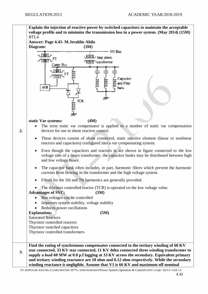
Explain the injection of reactive power by switched capacitors to maintain the acceptable
voltage profile and to minimize the transmission loss in a power system. (May 2014) (15M)
BTL4
Answer: Page 4.43- M.Jeraldin Ahila
Diagram: (3M)
static Var systems: (4M)
The term static var compensator is applied to a number of static var compensation
devices for use in shunt reactive control.
These devices consist of shunt connected, static reactive element (linear or nonlinear
reactors and capacitors) configured into a var compensating system.
Even though the capacitors and reactors in are shown in figure connected to the low
voltage side of a down transformer, the capacitor banks may be distributed between high
and low voltage buses.
The capacitor bank often includes, in part, harmonic filters which prevent the harmonic
currents from flowing in the transformer and the high voltage system.
Filters for the 5th and 7th harmonics are generally provided.
The thyristor controlled reactor (TCR) is operated on the low voltage value.
Advantages of SVC: (3M)
Bus voltages can be controlled
Improves system stability, voltage stability
Reduces power oscillations
Explanation: (5M)
Saturated Reactors
Thyristor controlled reactors
Thyristor switched capacitors
Thyristor controlled transformers
3.
Find the rating of synchronous compensator connected to the tertiary winding of 60 KV
star connected, 33 KV star connected, 11 KV delta connected three winding transformer to
supply a load 60 MW at 0.8 p.f lagging at 33 KV across the secondary. Equivalent primary
and tertiary winding reactance are 18 ohm and 0.12 ohm respectively. While the secondary
winding reactance is negligible. Assume that V1 is 66 KV and maximum off nominal

REGULATION:2013 ACADEMIC YEAR:2018-2019
JIT-JEPPIAAR /EEE/Mrs.S.SARUMATHI/ IIIrdYr /SEM 06/EE6603/Power System Operation & Control/UNIT1-5/QB+ KEYS /VER 1.0 4.33
setting between transformer primary and secondary is 1:1.1. (Nov 2018) (15M) BTL4
Answer: Page 4.43- M.Jeraldin Ahila
Voltage value: (5M)
t=1.1
P and Q Value: (5M)
: (5M)
11 MVAR/ph
Total reactive power required for synchronous compensation 3 = 3*11=33 MVAR
4.
Explain with neat diagrams and V-I characteristics, the basic operation of TCR and TSC.
(April/May 2018) (15M)
Answer: Page 4.46- M.Jeraldin Ahila
Explanation: (3M)
Discrete leading VARs from the capacitors and continuous lagging VAR from thyristor
controlled reactors.
Diagram: (6M)
V-I Characteristics: (6M)

REGULATION:2013 ACADEMIC YEAR:2018-2019
JIT-JEPPIAAR /EEE/Mrs.S.SARUMATHI/ IIIrdYr /SEM 06/EE6603/Power System Operation & Control/UNIT1-5/QB+ KEYS /VER 1.0 4.34

REGULATION:2013 ACADEMIC YEAR:2018-2019
JIT-JEPPIAAR /EEE/Mrs.S.SARUMATHI/ IIIrdYr /SEM 05/EE6603/Power System Operation & Control/UNIT1-5/QB+ KEYS /VER 1.0 4.35
UNIT IV-UNIT COMMITMENT AND ECONOMIC DISPATCH
Formulation of economic dispatch problem – I/O cost characterization – incremental cost curve -
co-ordination equations without and with loss (No derivation of loss coefficients) - solution by
direct method and λ-iteration method - statement of unit commitment problem – priority-list
method - forward dynamic programming.
PART *A
Q.No. Questions
1.
What is meant by priority list method? (May/June 2016) BTL1
Priority list method is the simplest unit commitment solution method which consists of creating
a priority list of units
The priority list can be obtained by nothing the full load average production cost of each unit.
2.
Compare unit commitment and economic load dispatch problems. (May 2018)
(Nov 2018)BTL4
Unit Commitment Economic dispatch
Optimum allocation of number of units to be
operated (to determine the units of a plant
that should operate for a given load is the
problem of unit commitment)
Optimum allocation of generation to each
station. (At each generating station at various
station load levels)
There are number of subsets of the complete
set of n units that would satisfy the expected
demand.
The problem assumes that there are n units
already connected to the system.
3.
State the need for unit commitment. BTL4
Enough units will be committed to supply the system load
To reduce the loss or fuel cost
By running the most economic unit, the load can be supplied by that unit operating closer
to its efficiency
4.
Define spinning reserve constraint in unit commitment problem. (Nov 2012) BTL1
Spinning reserve is one of the most important constraint in unit commitment problem. It is
defined as the total amount of generation available from all units which is synchronized on the
system subtracted with the present load and losses being supplied.
5.
What is the significance of unit commitment? (May 2012) BTL2
It minimizes the loss and the fuel cost
It commits the enough units to supply the system load.
It chooses the most economic unit for running to meet out the load so that the unit will
operate closer to its best efficiency.
6.
What is incremental cost criterion? (Nov 2012) BTL1
For the unit commitment table, fuel cost curve of the plant can be determined in the form of least
square fit. If transmission losses are neglected, the total system load can be optimally divided
among the various generating plants using the incremental cost criteria
= λ

REGULATION:2013 ACADEMIC YEAR:2018-2019
JIT-JEPPIAAR /EEE/Mrs.S.SARUMATHI/ IIIrdYr /SEM 05/EE6603/Power System Operation & Control/UNIT1-5/QB+ KEYS /VER 1.0 4.36
7.
Write the equality and inequality constraints considered in the economic dispatch
problem. (Nov 2011) BTL1
Equality constraints are the basic load flow equation is given by
Inequality constraints:
Generator constraints
Voltage constraints
Transformer tap setting
Transmission line constraints
8.
What is meant by FLAPC? (Nov/Dec 2017) BTL1
FLAPC-Full load average production cost.
FLAPC = {Net heat rate at full load}*Fuel cost
= = K.
9.
Write the condition for optimal power dispatch in a lossless system. (Nov/Dec 2017) BTL4
The necessary condition for the existence of a minimum cost operating condition is that the
incremental cost rates of all the units to be equal to some undetermined value of Lagrangian
multiplier (λ).
=
10.
What are the constraints in unit commitment? (April/May 2017) BTL2
Spinning reserve
Thermal constraints
Minimum uptime
Minimum down time
Crew constraint
Other constraints
Hydro constraint
Must run constraint
Fuel constraint
11.
Define incremental cost in power dispatch. (April/May 2017) BTL1
The incremental fuel cost of all the generating units must be the same. The common value of
incremental fuel cost (λ) is called the system incremental cost.
C = cost function
Power generation
12. State the unit commitment problem. BTL1
To select the generating units that will supply the forecasted (estimated load in advance) load of

REGULATION:2013 ACADEMIC YEAR:2018-2019
JIT-JEPPIAAR /EEE/Mrs.S.SARUMATHI/ IIIrdYr /SEM 05/EE6603/Power System Operation & Control/UNIT1-5/QB+ KEYS /VER 1.0 4.37
the system over a required period of time at minimum cost as well as provide a specified margin
of the operating reserve, known as the spinning reserve. This procedure is known as unit
commitment.
13.
Define merit order scheduling. BTL1
Merit order scheduling ensures that the incremental cost of all the generators is constant over the
full range (or) over successive discrete portions within the range. This method of scheduling is
known as merit order scheduling.
14.
Name the methods of finding economic dispatch. BTL1
The two methods to find economic dispatch are
Load scheduling
Unit commitment
15.
Write about the term incremental operating cost of the power system.
(Nov/Dec 2016)BTL4
The incremental fuel cost of all the generating units must be the same. The common value of
incremental fuel cost λ is called the system incremental cost.
16.
What is exact coordination equation? BTL1
= λ
IC = Incremental cost
ITL = Incremental transmission loss
17.
Define the term penalty factor. BTL1
= =
=
is called penalty factor
18.
State the difference between load frequency controller and economic dispatch controller.
BTL4
The load frequency controller is a fast acting controller and the economic dispatch controller in a
slow acting control.LFC adjusts the speed changes setting every minute in accordance with a
command signal generated by the central economic dispatch controller.
19.
Define Lagrangian multiplier. BTL1
The necessary condition for the existence of a minimum cost operating condition is that the
incremental cost rates of all the units be equal to some undetermined value (λ) called lagrangian
multiplier.
=
20.
State the advantages of using participation factor. BTL4
Computed implementation of economic dispatch is straight forward
Execution time for economic dispatch is short.
It will always give consistent answers when unit reach limits.
It gives linear incremental cost functions or have non convex cost curves.

REGULATION:2013 ACADEMIC YEAR:2018-2019
JIT-JEPPIAAR /EEE/Mrs.S.SARUMATHI/ IIIrdYr /SEM 05/EE6603/Power System Operation & Control/UNIT1-5/QB+ KEYS /VER 1.0 4.38
21.
What are all the point to be noted for an economic load dispatch including transmission
losses? BTL4
The incremental cost of production of a plant is always positive, the incremental
transmission losses can be both positive and negative.
The individual generators will operate at different incremental cost of production
The generation with highest positive incremental transmission loss will operate at lowest
incremental cost of production.
22.
Relate the necessary condition for the existence of minimum cost operating for the thermal
power system. (May 2018) BTL4
The minimum condition is that the incremental cost rates of all units be equal to understand (λ).
In addition to this condition, adding the constraint equation that the sum of power outputs must
be equal to the power demanded by the load.
= N equation
2N equation
23. Define crew constraints. (Nov 2018) BTL1
If a plant consists of two or more units, they cannot both be turned on at the same time. Since
there are not enough crew members to attend both units while starting up.
PART*B
1.
Explain various constraints in UC and indicate the steps involved in solving unit
commitment by Dynamic programming method. (May 2012) (13M) BTL4
Answer: Page 5.1 and 5.13- M.Jeraldin Ahila
Unit commitment problem: (2M)
The expected system demand levels for -24 hrs of tomorrow and the operating cost, startup cost
and shut down cost of the available N units.
If N generating units, (2N -1) number of combination obtained.
Constraints: (2M)
Spinning reserve
Thermal constraints-Minimum up time and down time-crew constraint
Other constraints-Hydro constraint-Must run constraint-Fuel constraints
Forward dynamic programming: (4M)
Unit commitment table is arrived for the complete load cycle.
Algorithm-run forward from initial hour to final hour.
Previous history of unit computed at each stage.
Initial conditions are easily specified.
Flowchart: (5M)
2.
Formulate the co-ordination equations with losses neglected and also explain the
algorithmic steps of iterative method to find the solution of coordination equations. (May 2012) (13M) BTL4
Draw the flowchart for obtaining the optimum dispatch strategy of N bus system
neglecting the system transmission loss. (Nov 2015) (13M) BTL4
Answer: Page 6.13- M.Jeraldin Ahila
Cost function: (3M)
Minimize C =
C = operating cost
Lagrangian multiplier: (2M)

REGULATION:2013 ACADEMIC YEAR:2018-2019
JIT-JEPPIAAR /EEE/Mrs.S.SARUMATHI/ IIIrdYr /SEM 05/EE6603/Power System Operation & Control/UNIT1-5/QB+ KEYS /VER 1.0 4.39
Minimum objective function: (2M)
Calculate λ : (1M)
Flowchart: (5M)
3.
Explain the λ-iteration method for finding the solution of economic dispatch including
transmission losses with a flowchart. (Nov 2012) (13M) BTL5
Answer: Page 6.46- M.Jeraldin Ahila
Compute λ : (3M)
Transmission loss: (4M)
Flowchart: (6M)
4.
(i)With the help of flowchart explain economic dispatch by λ-iteration method without
loss. (May 2013) (8M) BTL4
Answer: Page 6.16- M.Jeraldin Ahila
Calculate λ : (2M)
Compute : (2M)
Power balance equation: (2M)
Optimum solution: (2M)
(ii) Define the following. (Nov 2012) (5M) BTL2

REGULATION:2013 ACADEMIC YEAR:2018-2019
JIT-JEPPIAAR /EEE/Mrs.S.SARUMATHI/ IIIrdYr /SEM 05/EE6603/Power System Operation & Control/UNIT1-5/QB+ KEYS /VER 1.0 4.40
Answer: Page 5.3- M.Jeraldin Ahila
Minimum up time: (1M)
Once the unit-running-should not turned off immediately.
Minimum down time: (2M)
Once the unit-decommited-minimum time-before recommitted.
Spinning reserve: (2M)
Spinning reserve is one of the most important constraint in unit commitment problem.
It is defined as the total amount of generation available from all units which is
synchronized on the system subtracted with the present load and losses being supplied.
5.
Derive the coordination equation for economic dispatch with and without loss. (Nov 2014)
(13M) BTL3
Answer: Page 6.13 and 6.43- M.Jeraldin Ahila
Economic dispatch with loss: (6M)
Minimize C =
C = operating cost
=
= =
=
is called penalty factor
Economic dispatch without loss: (7M)
6.
Explain the priority list method for unit commitment problem with an example.
(Nov 2012) (13M) BTL4
Answer: Page 5.2- M.Jeraldin Ahila
Priority list method: (3M)
Creates priority list of unit.
FLAPC-Full load average production cost.
FLAPC = {Net heat rate at full load}*Fuel cost
= = K.
Assumption: (3M)
No load costs are zero.
Startup cost are fixed amount.
Ignore minimum up and down time.
Unit commitment example: (7M)
FLAPC
= = 9.79

REGULATION:2013 ACADEMIC YEAR:2018-2019
JIT-JEPPIAAR /EEE/Mrs.S.SARUMATHI/ IIIrdYr /SEM 05/EE6603/Power System Operation & Control/UNIT1-5/QB+ KEYS /VER 1.0 4.41
= = 9.4
= = 11.188
Priority order
Unit FLAPC Min (MW) Max (MW)
2 9.4 100 400
1 9.79 150 600
3 11.188 50 200
Unit commitment
Combination Minimum MW from
combination
Maximum MW
from combination
2+1+3 300 1200
2+1 250 1000
2 100 400
7.
State the unit commitment problem. With the help of a flowchart, explain forward
dynamic programming solution method of unit commitment problem.
(Nov 2013,2014,2018) (13M) BTL5
Answer: Page 5.2 and 5.15- M.Jeraldin Ahila
Unit commitment problem: (3M)
The expected system demand levels for -24 hrs of tomorrow and the operating cost, startup cost
and shut down cost of the available N units.
If N generating units, (2N -1) number of combination obtained.
Forward dynamic programming: (4M)
Unit commitment table is arrived for the complete load cycle.
Algorithm-run forward from initial hour to final hour.
Previous history of unit computed at each stage.
Initial conditions are easily specified.
Flowchart: (6M)
8.
(i)What is the significance of equality and inequality constraints in the formulation of
optimal dispatch problem? (May 2013) (4M) BTL2
Answer: Page 6.12- M.Jeraldin Ahila
Significance: (4M)
Total generation = Total demand
Particular generator reaches the limit, its loading from now on is held fixed at this value
Balanced load shared between the remaining generators on equal incremental cost basis.
(ii) The fuel cost function for the three thermal plants in Rs/h are given by

REGULATION:2013 ACADEMIC YEAR:2018-2019
JIT-JEPPIAAR /EEE/Mrs.S.SARUMATHI/ IIIrdYr /SEM 05/EE6603/Power System Operation & Control/UNIT1-5/QB+ KEYS /VER 1.0 4.42
0.004
0.006
0.009
Where P1 ,P2, P3 are in MW. The total load is 925 MW. Find the optimal dispatch and the
total cost in Rs/h. (May 2017) (Nov 2018) (9M) BTL3
100 MW
100 MW
100 MW
Compute λ: (1M)
= 8.9737
Compute : (3M)
Incremental cost rule: (1M)
Optimum schedule: (4M)
390.524 MW
350MW
184.476MW
9.
(i) The fuel cost of two units are given by
0.1
1.9+ 0.1
If the total demand on the generator is 200 MW. Find the economic load scheduling of the
two units. (May 2013) (4M) BTL3
Answer: Page 6.20- M.Jeraldin Ahila Economic dispatch: (1M)
Condition: (1M)
=

REGULATION:2013 ACADEMIC YEAR:2018-2019
JIT-JEPPIAAR /EEE/Mrs.S.SARUMATHI/ IIIrdYr /SEM 05/EE6603/Power System Operation & Control/UNIT1-5/QB+ KEYS /VER 1.0 4.43
Generation value: (1M)
= 150 MW
= 50 MW
(ii) Create a unit commitment using the priority list method for the following three units.
The fuel cost equation are as follows: PD = 800 MW. (May 2018) (9M) BTL3
; 150
; 100
; 50
Answer: Page 5.6- M.Jeraldin Ahila FLAPC: (3M)
= = 9.79
= = 9.4
= = 11.188
Priority order: (3M)
Unit FLAPC Min (MW) Max (MW)
2 9.4 100 400
1 9.79 150 600
3 11.188 50 200
Unit commitment: (3M)
Combination Minimum MW from
combination
Maximum MW
from combination
2+1+3 300 1200
2+1 250 1000
2 100 400
10.
Obtain the priority list of unit commitment using full load average production cost for the
given data:
0.00142
310+ 0.00194

REGULATION:2013 ACADEMIC YEAR:2018-2019
JIT-JEPPIAAR /EEE/Mrs.S.SARUMATHI/ IIIrdYr /SEM 05/EE6603/Power System Operation & Control/UNIT1-5/QB+ KEYS /VER 1.0 4.44
78+ 0.00483
Unit Min (MW) Max (MW) Fuel cost (k)
1 150 600 1.1
2 100 400 1.0
3 50 200 1.2
PD = 500 MW. (May 2013) (10M) BTL3
Answer: Page 5.12- M.Jeraldin Ahila
FLAPC: (4M)
= = 9.79
= = 9.4
= = 11.188
Priority order: (3M)
Unit FLAPC Min (MW) Max (MW)
2 9.4 100 400
1 9.79 150 600
3 11.188 50 200
Unit commitment: (3M)
Combination Minimum MW from
combination
Maximum MW
from combination
2+1+3 300 1200
2+1 250 1000
2 100 400
11.
The incremental cost of three units in a plant are
Where are power output in MW. Determine the optimum load allocation
when the total is 242.5 MW. Using participating factors, determine the optimum
scheduling when the load increased to 250 MW. (May 2018) (13M) BTL3
Answer: Page 6.68- M.Jeraldin Ahila
Incremental cost rule: (3M)

REGULATION:2013 ACADEMIC YEAR:2018-2019
JIT-JEPPIAAR /EEE/Mrs.S.SARUMATHI/ IIIrdYr /SEM 05/EE6603/Power System Operation & Control/UNIT1-5/QB+ KEYS /VER 1.0 4.45
= =λ
λ = 210 Rs/Mwh
Optimum load allocation: (3M)
Change in Generation: (4M)
Optimum Schedule: (3M)
= 65.4655 MW
PART*C
1.
The fuel inputs per hour of plants 1 and 2 are given as
0.2
0.25
Determine the economic operating schedule and the corresponding cost of generation if the
maximum and minimum loading on each unit is 100 MW and 25 MW.Assume the
transmission losses are ignored and the total demand is 180 MW. Also determine the
saving obtained if the load is equally shared by both the units. (Nov 2011,13) (15M) BTL3
Answer: Page S.55- M.Jeraldin Ahila
Compute λ : (3M)
= 0.4
= 0.5
= 75.56
and (4M)

REGULATION:2013 ACADEMIC YEAR:2018-2019
JIT-JEPPIAAR /EEE/Mrs.S.SARUMATHI/ IIIrdYr /SEM 05/EE6603/Power System Operation & Control/UNIT1-5/QB+ KEYS /VER 1.0 4.46
Check for limit: (1M)
Cost of generation: (5M)
5256.64 Rs/hr
4957.80 Rs/hr
Total Cost = 10214.44 Rs/hr
Net Saving: (2M)
Net Saving = 0.56 Rs/hr
2.
Determine the priority list using full load average production cost for the data given below.
Loading units Fuel cost parameter
Unit no Minimum Maximum ai bi ci Fuel cost
1 100 400 0.006 7 600 1.1
2 50 300 0.01 8 400 1.2
3 150 500 0.008 6 500 1.0
Also obtain unit commitment solution for the power demand of 800 MW. (May 2014)
(15M) BTL3
Answer: Page 5.10- M.Jeraldin Ahila
0.006
400+ 0.01
500+ 0.008
FLAPC: (5M)
= = 11.99
= = 14.8
= = 11
Priority order: (3M)
Unit FLAPC Min (MW) Max (MW)
3 11 150 500
1 11.99 100 400

REGULATION:2013 ACADEMIC YEAR:2018-2019
JIT-JEPPIAAR /EEE/Mrs.S.SARUMATHI/ IIIrdYr /SEM 05/EE6603/Power System Operation & Control/UNIT1-5/QB+ KEYS /VER 1.0 4.47
2 14.8 50 300
Unit commitment: (3M)
Combination Minimum MW from
combination
Maximum MW
from combination
3+1+2 300 1200
2+1 250 900
2 150 500
3.
A heat rate of 100 MW fuel fired generator is
10 MKcal\MWhr at 25% rating
9 MKcal\MWhr at 40% rating
8 MKcal\MWhr at 100% rating
Find fuel cost at 25,40,100%loading Incremental cost and Fuel input rate using quadratic
approximation to deliver 101 MW. (May 2014) (15M) BTL3
Answer: Page 6.27- M.Jeraldin Ahila
Heat rate: (4M)
+
+ *25 =10
+ *40 =9
+ *100 =8
Fuel cost: (4M)
)* = 66.66+ 7.33
Fuel input rate: (4M)
At 25% rating:
F(25) = 66.66+7.33*25 = 250MK cal/hr
C(25) = K*F(25) = 2*250 = 500 Rs/hr
At 40% rating:
F(40) = 66.66+7.33*40 = 360MK cal/hr
C(40) = K*F(40) = 2*360 = 720 Rs/hr
At 100% rating:
F(100) = 66.66+7.33*100 = 800MK cal/hr
C(100) = K*F(100) = 2*360 = 1600 Rs/hr
Quadratic approximation: (3M)
C(101) = 2*66.66+2*7.33*101 = 1614 Rs/hr

REGULATION:2013 ACADEMIC YEAR:2018-2019
JIT-JEPPIAAR /EEE/Mrs.S.SARUMATHI/ IIIrdYr /SEM 06/EE6603/Power System Operation & Control/UNIT1-5/QB+ KEYS /VER 1.0 4.48
UNIT V-COMPUTER CONTROL OF POWER SYSTEMS
Need for computer control of power systems - concept of energy control centre - functions - system
monitoring - data acquisition and control - system hardware configuration – SCADA and EMS
functions - network topology - state estimation – WLSE - Contingency Analysis - state transition
diagram showing various state transitions and control strategies.
PART *A
Q.No. Questions
1.
Define Energy control centre. BTL1
The operation and interaction become more complex in power system, when its size increases.
So its necessary to monitor the information for every second for the total system is called energy
control centre.
2.
What are the major functions that are carried out in an operations of control centre?
(Nov 2016) BTL4
System monitoring
Contingency analysis
Security constrained optimal power flow
Unit commitment
Maintenance scheduling
State estimation
Load frequency control
3.
What is SCADA? (May 2012) (Nov 2012) BTL1
SCADA is Supervisory Control and Data Acquisition system that allows operators to monitor
the generation and HV transmission system.
4.
What are the functions of SCADA? (May 2013) (Nov 13,16) BTL1
Monitoring
Data acquisition
Alarm
Data logging
ON/OFF control
Control and indication of AGC
5.
Define EMS system. (Nov 2011) BTL1 Energy management system is the process of monitoring, coordinating and controlling the
generation, transmission and distribution of electrical energy. It is performed at centre called
system control centres by a computer system called Energy Management system.
6.
What are the objectives of Automatic Generation Control? (May 2014) BTL4
To maintain each unit generation at the most economic value.
To hold frequency at very close to a specified nominal value.
To maintain the correct value of interchange power between control areas.

REGULATION:2013 ACADEMIC YEAR:2018-2019
JIT-JEPPIAAR /EEE/Mrs.S.SARUMATHI/ IIIrdYr /SEM 06/EE6603/Power System Operation & Control/UNIT1-5/QB+ KEYS /VER 1.0 4.49
7.
Define state estimation. (May 2013) (Nov 2013) BTL1
State estimation is the process of assigning a value to an unknown system states variable based
on measurements from that system according to minimizing the sum of the squares of the
differences between estimated and true value of the function.
8.
Define restorative state. (May 2014) BTL1
In restorative state, the control action is being taken to reconnect all the facilities and to restore
the system load to the normal state.
9.
What is the function of load dispatch centre? (Nov 2011, May 2012) BTL1
Loading of generating stations.
Control of system voltage and reactive power flow.
Loading of units within the generating station.
10.
How is load forecasting classified? BTL2
Long term forecasting
Medium term forecasting
Short term forecasting
Very short forecasting
11.
What are the states of power system? (Nov/Dec 2015) BTL1
Normal state
Alert state
Emergency state
In-Extremis state
Restorative state
12.
What are the functions of control center? (Nov/Dec 2015) BTL4
System monitoring
Contingency analysis
Security constrained optimal power flow
Unit commitment
Maintenance scheduling
State estimation
Load frequency control
13.
What are responsibilities of regional load dispatch centres? (April/May 2015) BTL2
Regional load dispatch centre decides generation allocation to various generating station within
the region on basic of equal incremental cost, line losses and frequency control.
14.
List the applications of SCADA. (Nov/Dec 2014) BTL1
Used to manage a physical process in many industries.
Used to make sure that productivity targets are met and all systems run smoothly in
manufacturing
Used in food production industries
Used to control the movement of power and gas throughout the distribution chain.
15.
State the weight least square criterion. (April/May 2018) BTL2
The weighted least square criterion, where the objective is to minimize the sum of the square of
the weighted deviations of the estimated measurements from actual measurements.

REGULATION:2013 ACADEMIC YEAR:2018-2019
JIT-JEPPIAAR /EEE/Mrs.S.SARUMATHI/ IIIrdYr /SEM 06/EE6603/Power System Operation & Control/UNIT1-5/QB+ KEYS /VER 1.0 4.50
16.
List out the condition for normal operation of a power system. (April/May 2017) BTL1
A system is said to be in normal state if both load and operating constraints are satisfied. It is
one in which the total demand on the system is met by satisfying all the operating constraints.
(equality and inequality constraints)
17.
Define Network Topology in a power system. BTL1
In order to run the state estimation, we must know how the transmission lines are connected to
the load and generation buses. This information is called network topology
18.
What is contingency analysis program? BTL1
The problems occur on a power system and cause serious trouble and the time –period to rectify
it is insufficient and hence causes cascading failures. Due to this, the modern operation
computers are equipped with contingency analysis programme.
19.
State the typical sensors used in power system applications. BTL2
Signal conditioners
Multiplexers
A/D converters
20.
Distinguish between reliability and security of a power system.
Reliability is a probabilistic index defined as the long term average number of days on
which daily peak loads exceeds the available generating capacity.
Security depends upon the reserve capacity available in a given situation and the
contingency probability of distribution.
21. State the weight least square criterion. (May 2018) (Nov 2018) BTL1
The weighted least square criterion, where the objective is to minimize the sum of the square of
the weighted derivations of the estimated measurements from the actual measurements.
22.
What are the priorities for operation of modern power system? (Nov 2018) BTL2
Normal state
Alert state
Emergency state
Extremis state
Restorative state
are the priorities for operation of modern power system.
PART*B
1.
Briefly explain various functions of SCADA with a neat diagram. (Nov 2011,2012)
(May 2012) (13M) BTL4
Explain the hardware configuration and function of SCADA. (Nov 2015,2018) (13M) BTL4
Answer: Page 7.12- M.Jeraldin Ahila
Diagram: (4M)

REGULATION:2013 ACADEMIC YEAR:2018-2019
JIT-JEPPIAAR /EEE/Mrs.S.SARUMATHI/ IIIrdYr /SEM 06/EE6603/Power System Operation & Control/UNIT1-5/QB+ KEYS /VER 1.0 4.51
SCADA: (3M)
There are two parts to the term SCADA Supervisory control indicates that the operator,
residing in the energy control center (ECC), has the ability to control remote equipment.
Data acquisition indicates that information is gathered characterizing the state of the
remote equipment and sent to the ECC for monitoring purposes.
The monitoring equipment is normally located in the substations and is consolidated is
known as the RTU
Function: (4M)
Data acquisition
Information display.
Supervisory Control
Information storage and result display.
Sequence of events acquisition
Control Function: (2M)
Dynamic Bus bar coloring according to their actual operational status.
Automatic switching sequences.
2. Explain various state transition and controls strategies using state transition diagram.
(Nov 2011) (13M) BTL4
Answer: Page 7.47- M.Jeraldin Ahila
Diagram: (6M)

REGULATION:2013 ACADEMIC YEAR:2018-2019
JIT-JEPPIAAR /EEE/Mrs.S.SARUMATHI/ IIIrdYr /SEM 06/EE6603/Power System Operation & Control/UNIT1-5/QB+ KEYS /VER 1.0 4.52
Explanation: (7M)
Normal state
Alert state
Emergency
Extremis
Restorative
3.
Discuss the various functions, system monitoring and control of load dispatch center.
(May 2012) (13M) BTL4
Answer: Page 7.5- M.Jeraldin Ahila
Functions: (4M)
Coordinate the response of the system in both normal and emergency condition.
Digital computer-process the income stream data to detect abnormalities.
System monitoring: (4M)
Loss of many generators or excess power demand by neighboring utility on tie lines
Many Alarm could be detected
System could enter an emergency state.
Control: (5M)
4.
Enumerate the operating states and the control strategies of a power system. (Nov 2012)
(13M) BTL5
Explain the different operating states in the security perspective with an example.
(Nov 2015) (13M) BTL5
Explain the various operating stages of power system. Also discuss the state transition
and control strategies. (Nov 2014) (13M) BTL5
What is normal operating state of a power system? Describe in detail the various state
that a power system takes, with their operating conditions.(May 2015) (13M) BTL5
Answer: Page 7.47- M.Jeraldin Ahila
Diagram: (6M)

REGULATION:2013 ACADEMIC YEAR:2018-2019
JIT-JEPPIAAR /EEE/Mrs.S.SARUMATHI/ IIIrdYr /SEM 06/EE6603/Power System Operation & Control/UNIT1-5/QB+ KEYS /VER 1.0 4.53
Normal state: (1M)
A system is said to be in normal if both load and operating constraints are satisfied .It is one in
which the total demand on the system is met by satisfying all the operating constraints.
Alert state: (2M)
A normal state of the system said to be in alert state if one or more of the postulated contingency
states, consists of the constraint limits violated.
When the system security level falls below a certain level or the probability of disturbance
increases, the system may be in alert state.
Emergency state: (2M)
The system is said to be in emergency state if one or more operating constraints are violated, but
the load constraint is satisfied.
In this state, the equality constraints are unchanged.
Extremis state: (1M) When the system is in emergency, if no proper corrective action is taken in time, then it goes to
either emergency state or extremis state.
In this regard neither the load or nor the operating constraint is satisfied, this result is islanding.
Restorative state: (1M) From this state, the system may be brought back either to alert state or secure state .The latter is
a slow process.
Hence, in certain cases, first the system is brought back to alert state and then to the secure state
This is done using restorative control action.
5. (i)Explain the major functions of security control. (May 2013) (10M) BTL5
Answer: Page 7.17- M.Jeraldin Ahila
Security monitoring system: (5M)
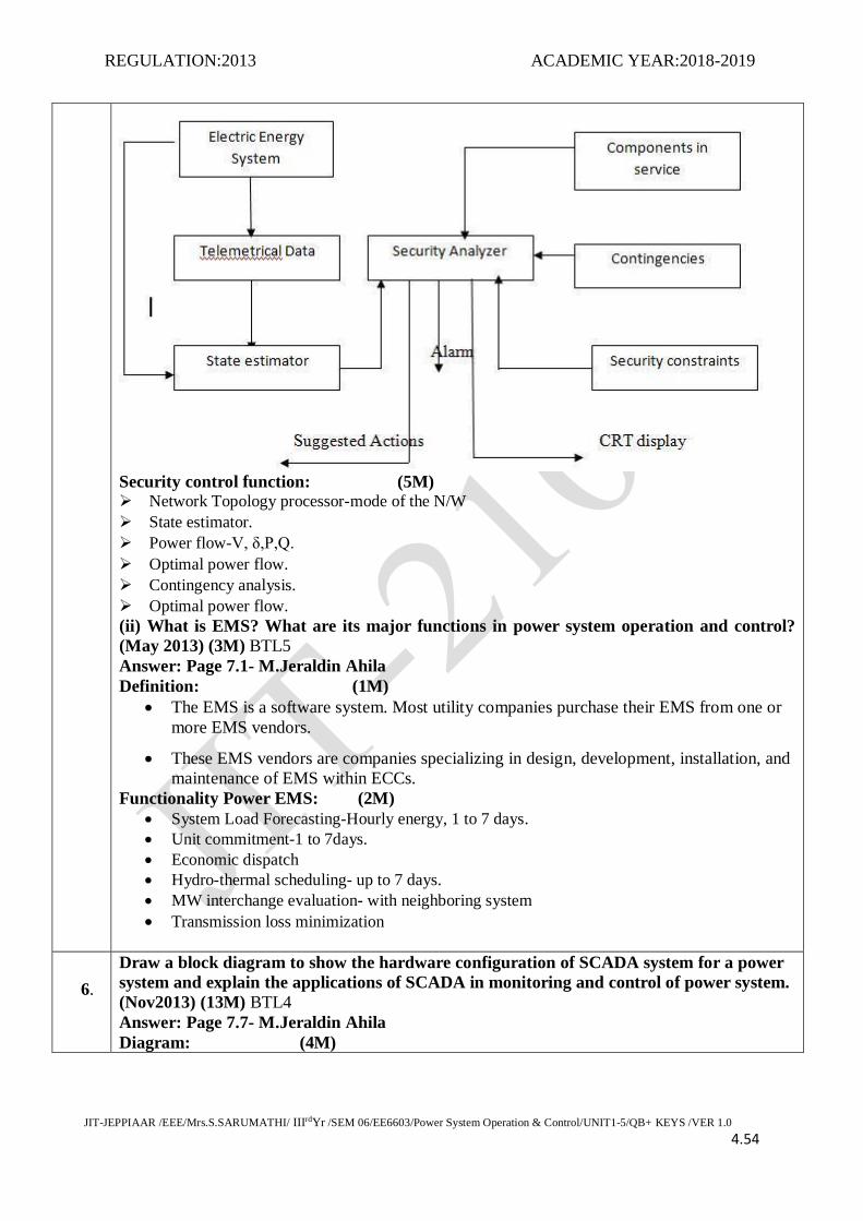
REGULATION:2013 ACADEMIC YEAR:2018-2019
JIT-JEPPIAAR /EEE/Mrs.S.SARUMATHI/ IIIrdYr /SEM 06/EE6603/Power System Operation & Control/UNIT1-5/QB+ KEYS /VER 1.0 4.54
Security control function: (5M) Network Topology processor-mode of the N/W
State estimator.
Power flow-V, δ,P,Q.
Optimal power flow.
Contingency analysis.
Optimal power flow.
(ii) What is EMS? What are its major functions in power system operation and control?
(May 2013) (3M) BTL5
Answer: Page 7.1- M.Jeraldin Ahila
Definition: (1M)
The EMS is a software system. Most utility companies purchase their EMS from one or
more EMS vendors.
These EMS vendors are companies specializing in design, development, installation, and
maintenance of EMS within ECCs.
Functionality Power EMS: (2M)
System Load Forecasting-Hourly energy, 1 to 7 days.
Unit commitment-1 to 7days.
Economic dispatch
Hydro-thermal scheduling- up to 7 days.
MW interchange evaluation- with neighboring system
Transmission loss minimization
6.
Draw a block diagram to show the hardware configuration of SCADA system for a power
system and explain the applications of SCADA in monitoring and control of power system.
(Nov2013) (13M) BTL4
Answer: Page 7.7- M.Jeraldin Ahila
Diagram: (4M)

REGULATION:2013 ACADEMIC YEAR:2018-2019
JIT-JEPPIAAR /EEE/Mrs.S.SARUMATHI/ IIIrdYr /SEM 06/EE6603/Power System Operation & Control/UNIT1-5/QB+ KEYS /VER 1.0 4.55
SCADA: (3M)
There are two parts to the term SCADA Supervisory control indicates that the operator,
residing in the energy control center (ECC), has the ability to control remote equipment.
Data acquisition indicates that information is gathered characterizing the state of the
remote equipment and sent to the ECC for monitoring purposes.
The monitoring equipment is normally located in the substations and is consolidated is
known as the RTU
Function: (4M)
Data acquisition
Information display.
Supervisory Control
Information storage and result display.
Sequence of events acquisition
Control Function: (2M)
Dynamic Bus bar coloring according to their actual operational status.
Automatic switching sequences.
PART*C
1.
Explain the concept of energy control centre or load dispatch centre. Also discuss its
functions. (Nov 2014,2018) (15M) BTL4
Answer: Page 7.3- M.Jeraldin Ahila
Energy control centre: (5M)
Energy Control Center (ECC) is designed and built for system operation. In order to have an
efficient power system operation and control, various control centers have to be operated in the
hierarchical level. The following Table shows the level decomposition of control centers in
the power system.
Classification: (5M)
i) Local Control Centre
ii) Area Load Dispatch Centre
iii) State Load Dispatch Centre

REGULATION:2013 ACADEMIC YEAR:2018-2019
JIT-JEPPIAAR /EEE/Mrs.S.SARUMATHI/ IIIrdYr /SEM 06/EE6603/Power System Operation & Control/UNIT1-5/QB+ KEYS /VER 1.0 4.56
iv) Regional Control Centre
Explanation: (5M)
Level System Monitoring and control
First Generating stations,
substations
Local control centre
Second Sub transmission and
transmission network
Area load dispatch centre
Third Transmission system State load dispatch centre
Fourth Interconnected power system Regional control centre
2.
What is state estimation with respect to power system? Explain briefly the method of
maximum likelihood weighted least squares estimation. (15M) (May 2015)BTL4
Answer: Page 7.28- M.Jeraldin Ahila
Definition: (2M)
State estimation Uses real-time status and analog measurements to determine the best estimate
of the state of the power system. It uses a redundant set of measurements; calculates voltages,
phase angles, and power flows for all components in the system; and reports overload
conditions.
Diagram: (5M)
Weighted least: (3M)
The weighted least square criterion, where the objective is to minimize the sum of the square of
the weighted derivations of the estimated measurements from the actual measurements.
Criterion: (5M)
Objective to minimize [J] the sum of the squares of the weighted deviations of the estimated
measurements.

REGULATION:2013 ACADEMIC YEAR:2018-2019
JIT-JEPPIAAR /EEE/Mrs.S.SARUMATHI/ IIIrdYr /SEM 06/EE6603/Power System Operation & Control/UNIT1-5/QB+ KEYS /VER 1.0 4.57
3.
Write short notes on state estimation? Explain the help of flow chart the weighted least
squares estimation. (15M) (May 2015) (Nov 2018)BTL4
Answer: Page 7.28- M.Jeraldin Ahila
Definition: (2M)
State estimation Uses real-time status and analog measurements to determine the best estimate
of the state of the power system. It uses a redundant set of measurements; calculates voltages,
phase angles, and power flows for all components in the system; and reports overload
conditions.
Flowchart: (5M)
Weighted least: (3M)
The weighted least square criterion, where the objective is to minimize the sum of the square of
the weighted derivations of the estimated measurements from the actual measurements.
Criterion: (5M)
Objective to minimize [J] the sum of the squares of the weighted deviations of the estimated
measurements.