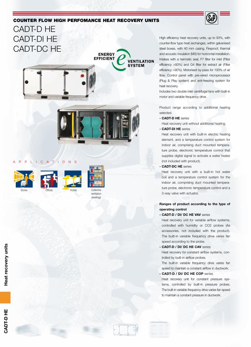
counter flow high perfomance heat recovery units … · high efficiency heat recovery units, up to...
TRANSCRIPT
Hea
t re
cove
ry u
nits
CA
DT-
D H
E
High efficiency heat recovery units, up to 93%, with
counter-flow type heat exchanges, within galvanised
steel boxes, with 40 mm casing. Fireproof, thermal
and acoustic insulation (M0) for horizontal installation.
Intakes with a hermetic seal, F7 filter for inlet (Filter
efficiency >93%) and G4 filter for extract air (Filter
efficiency >90%). Motorised by-pass for 100% of air
flow. Control panel with pre-wired microprocessor
(Plug & Play system) and anti-freezing system for
heat recovery.
Includes two double inlet centrifugal fans with built-in
motor and variable frequency drive.
Product range according to additional heating
selected.
- CADT-D HE series
Heat recovery unit without additional heating.
- CADT-DI HE series
Heat recovery unit with built-in electric heating
element, and a temperature control system for
indoor air, comprising duct mounted tempera-
ture probe, electronic temperature control that
supplies digital signal to activate a water heater
(not included with product).
- CADT-DC HE series
Heat recovery unit with a built-in hot water
coil and a temperature control system for the
indoor air, comprising duct mounted tempera-
ture probe, electronic temperature control and a
3-way valve with actuator.
Ranges of product according to the type of
operating control
- CADT-D / DI/ DC HE VAV series
Heat recovery unit for variable airflow systems,
controlled with humidity or CO2 probes (As
accessories, not included with the product).
The built-in variable frequency drive varies fan
speed according to the probe.
- CADT-D / DI/ DC HE CAV series
Heat recovery for constant airflow systems, con-
trolled by built-in airflow probes.
The built-in variable frequency drive varies fan
speed to maintain a constant airflow in ductwork.
- CADT-D / DI/ DC HE COP series
Heat recovery unit for constant pressure sys-
tems, controlled by built-in pressure probes.
The built-in variable frequency drive varies fan speed
to maintain a constant pressure in ductwork.
COUNTER FLOW HIGH PERFOMANCE HEAT RECOVERY UNITS
CADT-D HECADT-DI HECADT-DC HE
A P P L I C A T I O N S
Stores Offices Hotels Collectiveventilationdwellings

Hea
t re
cove
ry u
nits
CA
DT-
D H
E
2 high-efficiency filters
F7 filter for inlet air (Filtration
efficiency: >93%). G4 filter for
extracted air (Efficiency:>90%).
Robust construction
High quality finishing with
aluminium profile structure,
providing a robust assembly.
On-off switch
Built-in exterior on-off switch.
Pressure switch
Enables the degree of dirtiness of
the filters to be known.
Secure installation
Integrated hanging supports
to install the heat recovery unit.
By-Pass
By-pass damper enables 100%
of air to by-pass the heat
exchanger.
Reference
C A D T D
1 2 3 4 5 6 7
- C H E 1 0 0 0 D P D O M O V A V
1 - CADT: Series
2 - D: Standard range DI: Range with resistance incorporated DC: Range with water battery incorporated
3 - HE: High efficiency
4 - Size
5 - DP: Range with double wall insulation
6 - Control: PROGRAM, ADVANZ, DOMO
7 - VAV: Variable airflow CAV: Constant airfflow COP: Constant pressure

Hea
t re
cove
ry u
nits
CA
DT-
D H
E
Versions with an electronic microprocesor: Models and functions
PROGRAM ADVANZ DOMO
Manual fan speed selection: OFF + 3 speed
Manual fan speed selection: OFF + control of speed range [MIN-MAX] (alternative to 1 )
Imbalance between impulsion and extraction flow only for VAV versions with double inverter (does not apply to 3 speed versions)
Automatic control of fan speed: CO2, CO2/VOC and HR sensors with programmable PPM or HR range (by the installer); available for 3 speed versions and variable speed versions
Remote function of the fan speed signal is 0-10V (alternative to 4 )
Booster via remote NC contact at a pre-set time. Time can be altered by software
Remote "Boost" management by NC contact or proximity sensor (alternative to 6 and 8 )
Unit can be switched ON/OFF via remote switch (alternative to 6 or 7 )
Weekly programs
Prevention of icing of the heat exchanger (simple strategy): blower fan moves to low/off; Setting the extractor fan to maximum speed.
Prevention of build-up of frost in the heat exchanger: proportional mode management with pre-heating coils (alternative to 10 or 12 )
Exchanger frost prevention: Personalized funcions (through a switch NO-NC (alternative to 10 and 11 )
Management of electric post-heating (simple or double stage) in ON/OFF mode. The objective is to attain the average internal temperature value (Tr)
Management of electric post-heating in proportional mode. The objective is to attain the average internal temperature value (Tr) and to keep the impelled air within a set range (Ti)
Management of water coil post-heating in ON/OFF mode. The objective is to attain the average internal temperature value (Tr)
Management of water coil post-heating. The objective is to attain the average internal temperature value (Tr) and to keep the impelled air within a set range (Ti)
Management of post-cooling in proportional mode. The objective is to attain the average internal tem-perature value (Tr) and to keep the impelled air within a set range (Ti)
Remote signalling of the status of the unit via a volt free contact: closed contact=the unit is operating; open contact=the unit is stopped (alternative to 12 )
Monitoring of the state of the filters via period of operation of the equipment or via differential pressure sensors
Monitoring of the state of the fans via a tachometric signal (if supported by the fan) or via differential pressure sensors
1
2
3
4
5
6
7
8
9
10
11
12
13
14
15
16
17
18
19
20
3 3 3
3 3 3
3 3 3
3 3 3
3 3
3 3
3 3
3 3
3 3 3
3 3 3
3 3
3 3
3
3 3
3
3 3
3 3
3 3
3 3 3
3 3 3

Hea
t re
cove
ry u
nits
CA
DT-
D H
E
PROGRAM CONTROL CADT-DPRINCIPAL FEATURES Terminal cabinet includes:
Proximity sensor • Integrated circuit card and terminal box•
Remote control unit (100 m max.) Ready-mounted, ready-wired temperature sensors:
Discharge temperature sensor (Tx)• New air intake temperature sensor (Te)• Ambient air return temperature sensor (Tr)•
Vacuum regulator valve, ready-mounted and wired:Filter clogging• Security (operation of fans)•
Frequency regulator on three phase models OPTIONAL FEATURESCO2 sensor:
SCO2-010A ambient sensor with display / SCO2-010G in-duct measurement• ¥Self-regulating antifreeze battery:
ABE-SCT circular battery• ¥Differential pressure switch• ¥Timer• ¥TG-K310 duct-mountable temperature sensor -20 to + 10ºC• ¥TI-10 potentiometer -20 to + 10ºC for panel mounting• ¥
FUNCTIONSFlow rate adjustment:
Manual fan speed selection (single phase models) or variable (three phase models). •Timer boost function
Automatic modulation via built-in clock: daily and weekly programs •
Automatic speed settings (single phase models) or automatic speed variation •(Three phase models) based on air quality sensor readings (sensor optional)
Operates at constant pressure• *Free cooling function on models equipped with by-pass
Safety functions:Heat exchanger antifreeze protection (blower fan moves to low/off)• Filter clogging / vacuum regulator valve failure alarm • Temperature sensor fault alarm (wire severed, connection fault,...)• Console-control cabinet connection fault alarm• Included, ¥ Unmounted option
* Optional and on request
Electronic microprocessors - PROGRAM model - Features and functions
Schematic diagram
T return(ambient)
T new air intake T discharge
+
By-pass
CO2 Sensor
0/VL/VM/VR
Programmable timerBoost HS/ O� HS/LSSetpoint adjustmentAlarms
PROGRAM
Self-regulatingantifreeze battery
T supply air
T return(ambient)
T new air intake T discharge
+
By-pass
CO2 Sensor
0/VL/VM/VR
Programmable timerBoost HS/ O� HS/LSSetpoint adjustmentAlarms
PROGRAM
Self-regulatingantifreeze battery
T supply air
PROGRAM CONTROL CADT-DI CADT-DCPRINCIPAL FEATURES Terminal cabinet includes:
Proximity sensor•
Integrated circuit card and terminal box• Remote control unit (100 m max.)
Ready-mounted, ready-wired temperature sensors:Discharge temperature sensor (Tx)•
New air intake temperature sensor (Te)•
Ambient air return temperature sensor (Tr)•
Supply air temperature sensor (Ti)•
Vacuum regulator valve, ready-mounted and wired: Filter clogging•
Security (operation of fans)•
Frequency regulator on three phase models
OPTIONAL FEATURESMotorized 3-way control valve + 230V/24V transformer for hot water coil
- ¥
CO2 sensor:SCO2-010A ambient sensor with display / SCO2-010G in-duct •measurement ¥ ¥
Self-regulating antifreeze battery:ABE-SCT circular battery• ¥ ¥Differential pressure switch• ¥ ¥Timer• ¥ ¥TG-K310 duct-mountable temperature sensor -20 to + 10ºC• ¥ ¥TI-10 potentiometer -20 to + 10ºC for panel mounting• ¥ ¥
FUNCTIONSFlow rate adjustment:
Manual fan speed selection (single phase models) or variable •(three phase models). Timer boost function
Automatic modulation via built-in clock: daily and weekly •programs
Automatic speed settings (single phase models) or automatic •speed variation (Three phase models) based on air quality sensor readings (sensor optional)
Operates at constant pressure • * *Post heating battery regulation
Battery power regulation as per temperature setting and blower •sensor reading
Free cooling function on models equipped with by-pass
Safety functions:Heat exchanger antifreeze protection (blower fan moves to low/off)•
Fan shutdown timer setting for cooling electric battery •(postventilation)
-
Water coil antifreeze protection antigel de la batterie eau in each •sensor (opens 3-way control valve then stops power unit)
-
Filter clogging / vacuum regulator valve failure alarm •
Temperature sensor fault alarm (wire severed, connection fault,...)•
Ventilation fault alarm• Console-control cabinet connection fault alarm•
Included, - Not included, ¥ Unmounted option
* Optional and on request
CADT-DI HE with PROGRAM controlThe battery is regulated independently. The PROGRAM can not control it.HS: High speed LS: Low speed
CADT-DC HE with PROGRAM controlThe battery is regulated independently. The PROGRAM can not control it.HS: High speed LS: Low speed

Hea
t re
cove
ry u
nits
CA
DT-
D H
E
Electronic microprocessors - ADVANZ and DOMO models - Features and functions
ADVANZ AND DOMO CONTROLS CADT-DPRINCIPAL FEATURESTerminal cabinet includes:• Proximity sensor l
• Integrated circuit card and terminal box l
Remote control unit (100 m max.) (Only ADVANZ) l
Ready-mounted, ready-wired temperature sensors:• Discharge temperature sensor (Tx) l
• New air intake temperature sensor (Te) l
• Ambient air return temperature sensor (Tr) l
Vacuum regulator valve, ready-mounted and wired:• Filter clogging l
• Security (operation of fans) l
Frequency regulator on three phase models l
OPTIONAL FEATURESCO2 sensor:• SCO2-010A ambient sensor with display / SCO2-010G in-duct measurement ¥
Self-regulating antifreeze battery:• ABE-SCT circular battery ¥
• Differential pressure switch ¥
• Timer ¥
• TG-K310 duct-mountable temperature sensor -20 to + 10ºC ¥
• TI-10 potentiometer -20 to + 10ºC for panel mounting ¥
FUNCTIONSFlow rate adjustment:• Manual fan speed selection (single phase models) or variable (three phase models).
Timer boost functionl
• Automatic modulation via built-in clock: daily and weekly programs l
• Automatic speed settings (single phase models) or automatic speed variation(Three phase models) based on air quality sensor readings (sensor optional)
l
• Remote function of the fan speed signal is 0-10V l
• Operates at constant pressure *Free cooling function on models equipped with by-pass l
Remote "Boost" management by NC contact or proximity sensor l
Remote indication of unit status l
Exchanger frost prevention:• Heat exchanger antifreeze protection (blower fan moves to low/off) l
• Proportional management using an antifreeze battery (pre-heating)) l
• Personalized funcions (through a switch NO-NC) l
Remote signaling of unit status l
Panel language configuration (ES/EN/DE/IT/FR) l
Safety functions:• Filter clogging / vacuum regulator valve failure alarm l
• Temperature sensor fault alarm (wire severed, connection fault,...) l
• Console-control cabinet connection fault alarm l
• Communicator regulation [adjustment] (Only DOMO) l
l Included, ¥ Unmounted option
* Optional and on request
Schematic diagram
T new air intake T discharge Self-regulatingantifreeze battery
T return(ambient)
CO2 Sensor
0/VL/VM/VR
Programable timer Boost HS / O� HS/LSSetpoint adjustmentAlarms
ADVANZDOMO
Register
Network(DOMO)
Boost HR
Supply air
T new air intake T discharge Self-regulatingantifreeze battery
T return(ambient)
CO2 Sensor
0/VL/VM/VR
Programmable timerBoost HR / O� HS/LSSetpoint adjustmentAlarms
Network(DOMO)
Register
Boost HS
T supply air
ADVANZDOMO
ADVANZ AND DOMO CONTROLS CADT-DI CADT-DCPRINCIPAL FEATURESTerminal cabinet includes:• Proximity sensor l l• Integrated circuit card and terminal box l lRemote control unit (100 m max.) (Only ADVANZ) l lReady-mounted, ready-wired temperature sensors:• Discharge temperature sensor (Tx) l l• New air intake temperature sensor (Te) l l• Ambient air return temperature sensor (Tr) l l• Supply air temperature sensor (Ti) l lVacuum regulator valve, ready-mounted and wired:• Filter clogging l l• Security (operation of fans) l lSolid-state relay on electrical battery l -No-frost safety sensor on hot water battery - lFrequency regulator on three phase models l lOPTIONAL FEATURESMotorized 3-way control valve + 230V/24V transformer for hot water coil - ¥CO2 sensor:• SCO2-010A ambient sensor with display / SCO2-010G in-duct measurement ¥ ¥Self-regulating antifreeze battery:• ABE-SCT circular battery ¥ ¥• Differential pressure switch ¥ ¥• Timer ¥ ¥• TG-K310 duct-mountable temperature sensor -20 to + 10ºC ¥ ¥• TI-10 potentiometer -20 to + 10ºC for panel mounting ¥ ¥FUNCTIONSFlow rate adjustment:• Manual fan speed selection (single phase models) or variable
(three phase models). Timer boost functionl l
• Automatic modulation via built-in clock: daily and weekly programs l l
• Automatic speed settings (single phase models) or automatic speed variation (Three phase models) based on air quality sensor readings (sensor optional)
l l
• Remote function of the fan speed signal is 0-10V l l• Operates at constant pressure * *Post heating battery regulation• Battery power regulation as per temperature setting and blower sensor
readingl l
Free cooling function on models equipped with by-pass l lRemote "Boost" management by NC contact or proximity sensor l -Remote indication of unit status l lExchanger frost prevention:• Heat exchanger antifreeze protection (blower fan moves to low/off) l l• Proportional management using an antifreeze battery (pre-heating) l l• Personalized funcions (through a switch NO-NC) l lProportional function of post-heating or post-cooling l lRemote signaling of unit status l lPanel language configuration (ES/EN/DE/IT/FR) l lSafety functions:• Fan shutdown timer setting for cooling electric battery (postventilation) l l
• Water coil antifreeze protection antigel de la batterie eau in each sensor (opens 3-way control valve then stops power unit) - l
• Filter clogging / vacuum regulator valve failure alarm l l• Temperature sensor fault alarm (wire severed, connection fault,...) l l• Console-control cabinet connection fault alarm l l• Communicator regulation [adjustment] (Only DOMO) l l* Optional and on request
CADT-DI HE with ADVANZ / DOMO controlHS: High speed LS: Low speed
CADT-DC HE with ADVANZ / DOMO controlHS: High speed LS: Low speed

Hea
t re
cove
ry u
nits
CA
DT-
D H
E
Technical Characteristics
VAV, CAV and COP models without additional heatingModel Dimensions
(mm)
Volume
(m3)
Weight
(Kg)
Fan type
Speed
(r.p.m.)
Electrical supply
V (III)
Motor power
(kW)
Maximum absorbed current
(A)
Maximum volume
(m3/h)
Protection
(IP)
Efficiency *
(%)
CADT-D HE 1000 DP 1680X600X1080 1,089 165 9/7 1400 230 2x300 5 1200 20 93
CADT-D HE 2000 DP 1680X800X1205 1,620 220 10/8 1400 230 2x550 9 2400 20 93
CADT-D HE 3000 DP 1680X1080X1205 2,186 280 10/10 1400 400 2x750 7 3200 20 93
CADT-D HE 4500 DP 1850X1080X1580 3,157 355 12/9 1400 400 2x1500 11 4700 20 93
CADT-D HE 6000 DP 1850X1310X1580 3,829 415 12/9 1400 400 2x1500 11 6200 20 93
* Values referring to the following conditions: T ext = -5ºC, T exh = 20ºC, RH exhaust air = 50% / Maximum airflow.
VAV, CAV and COP models with integrated electric heaterModel Dimensions
(mm)
Volume
(m3)
Weight
(Kg)
Fan type
Fan type.
(r.p.m.)
Elec. supply.
V (III)
Motor power
Max. abs. current to 230V
(A)
Max. volume
(m3/h)
Prot.
(IP)
Effic.*
(%)
Resist. power
(kW)
Resist. voltage.
(V)
Resist.current
abs. (A)
Total maximum
current(A)
CADT-DI HE 1000 DP 1680X600X1080 1,089 165 9/7 1400 230 2x300 5 1200 20 93 4 230 17,50 22,50
CADT-DI HE 2000 DP 1680X800X1205 1,620 220 10/8 1400 230 2x550 9 2400 20 93 6 230 26,00 35,00
CADT-DI HE 3000 DP 1680X1080X1205 2,186 280 10/10 1400 400 2x750 7 3200 20 93 8 400 12,17 19,17
CADT-DI HE 4500 DP 1850X1080X1580 3,157 355 12/9 1400 400 2x1500 11 4700 20 93 12 400 31,60 42,60
CADT-DI HE 6000 DP 1850X1310X1580 3,829 415 12/9 1400 400 2x1500 11 6200 20 93 16 400 36,06 47,06
* Values referring to the following conditions: T ext = -5ºC, T exh = 20ºC, RH exhaust air = 50% / Maximum airflow.
VAV, CAV and COP models with integrated water coil
Model Dimensions
(mm)
Fan type
(m3)
Weight
(Kg)
Fan type
Speed
(r.p.m.)
Elec. supply
V (III)
Motor power
(kW)
Max. abs. current to
230V(A)
Max.volume
(m3/h)
Protection
(IP)
Efficiency*
(%)
Resist. power
(kW)
CADT-DC HE 1000 DP 1680X600X1080 1,089 165 9/7 1400 230 2x300 5 1200 20 93 6
CADT-DC HE 2000 DP 1680X800X1205 1,620 220 10/8 1400 230 2x550 9 2400 20 93 10
CADT-DC HE 3000 DP 1680X1080X1205 2,186 280 10/10 1400 400 2x750 7 3200 20 93 15
CADT-DC HE 4500 DP 1850X1080X1580 3,157 355 12/9 1400 400 2x1500 11 4700 20 93 24
CADT-DC HE 6000 DP 1850X1310X1580 3,829 415 12/9 1400 400 2x1500 11 6200 20 93 31
* Values referring to the following conditions: T ext = -5ºC, T exh = 20ºC, RH exhaust air = 50% / Maximum airflow.

Hea
t re
cove
ry u
nits
CA
DT-
D H
E
Dimensions (mm)
Evolution of the efficiency of recovery according to the flow
Configuration CADT-D/DI/DC HE
CADT-D-DI-DC HE:
EFF
ICIE
NC
Y (%
)
AIRFLOW (m3/h)
Model A B C D E L P S ØWeight
(Kg)
CADT-D/DI/DC HE 1000 1680 1080 500 280 410 400 980 1/2” 250 165
CADT-D/DI/DC HE 2000 1680 1205 700 310 480 400 1105 1/2” 315 220
CADT-D/DI/DC HE 3000 1680 1205 980 310 590 400 1105 1/2” 400 280
CADT-D/DI/DC HE 4500 1850 1580 980 405 590 500 1480 1/2” 450 355
CADT-D/DI/DC HE 6000 1850 1580 1210 405 705 500 1480 1/2” 500 415
Values with the following
conditions:
External air (T ext) = -5ºC,
exhaust air (T exh) = +20ºC
with interior RH of 50%.
Access to filter and heat recovery exchanger this side
FIlTRO
DESAGÜE
VENTIlADORCENTRÍFUGO
AIRE NUEVO
AIRE EXTRAIDO
BATERÍAElÉCTRICA
BATERÍADE AGUA
INlET FRESH AIR
EXTRACTED AIR
Hea
t re
cove
ry u
nits
CA
DT-
D H
E
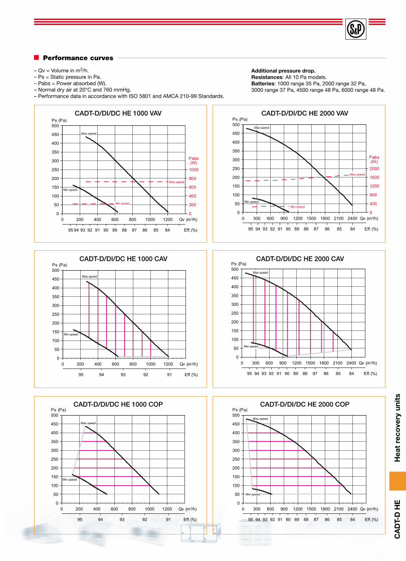
Performance curves
– Qv = Volume in m3/h.– Ps = Static pressure in Pa.– Pabs = Power absorbed (W).– Normal dry air at 20°C and 760 mmHg.– Performance data in accordance with ISO 5801 and AMCA 210-99 Standards.
Additional pressure drop.Resistances: All 10 Pa models.Batteries: 1000 range 35 Pa, 2000 range 32 Pa, 3000 range 37 Pa, 4500 range 48 Pa, 6000 range 48 Pa.
0 300 600 900 1200 1500 1800 2100 2400 Qv (m3/h)0
50
100
150
200
250
300
350
400
450
500Ps (Pa)
0
400
800
1200
1600
2000
Pabs(W)
848586878889909192939495 Eff. (%)
Max.speed
Max.speed
Min.speed
Min.speed
0 200 400 600 800 1000 1200 Qv (m3/h)0
50
100
150
200
250
300
350
400
450
500Ps (Pa)
0
200
400
600
800
1000
Pabs(W)
848586878889909192939495 Eff. (%)
Max.speed
Min.speed
Max.speed
Min.speed
CADT-D/DI/DC HE 1000 VAV CADT-D/DI/DC HE 2000 VAV
0 200 400 600 800 1000 1200 Qv (m3/h)0
50
100
150
200
250
300
350
400
450
500Ps (Pa)
9192939495 Eff. (%)
Max.speed
Min.speed
0 300 600 900 1200 1500 1800 2100 2400 Qv (m3/h)0
50
100
150
200
250
300
350
400
450
500P s (Pa)
848586878889909192939495 Eff. (%)
Max.speed
Min.speed
0 200 400 600 800 1000 1200 Qv (m3/h)0
50
100
150
200
250
300
350
400
450
500Ps (Pa)
9192939495 Eff. (%)
Max.speed
Min.speed
0 300 600 900 1200 1500 1800 2100 2400 Qv (m3/h)0
50
100
150
200
250
300
350
400
450
500Ps (Pa)
848586878889909192939495 Eff. (%)
Max.speed
Min.speed
CADT-D/DI/DC HE 1000 CAV CADT-D/DI/DC HE 2000 CAV
CADT-D/DI/DC HE 1000 COP CADT-D/DI/DC HE 2000 COP

Hea
t re
cove
ry u
nits
CA
DT-
D H
E
0 500 1000 1500 2000 2500 3000 3500 Qv (m3/h)0
50
100
150
200
250
300
350
400
450
500Ps (Pa)
0
500
1000
1500
2000
2500
Pabs(W)
848586878889909192939495 Eff. (%)
Max.speed
Min.speed
Max.speed
Min.speed
0 500 1000 1500 2000 2500 3000 3500 4000 4500 Qv (m3/h)0
100
200
300
400
500
600
700
800
900Ps (Pa)
0
800
1600
2400
3200
Pabs(W)
86878889909192939495 Eff. (%)
Max.speed
Min.speed
Min.speed
Max.speed
0 500 1000 1500 2000 2500 3000 3500 Qv (m3/h)0
50
100
150
200
250
300
350
400
450
500Ps (Pa)
848586878889909192939495 Eff. (%)
Max.speed
Min.speed
0 500 1000 1500 2000 2500 3000 3500 4000 4500 Qv (m3/h)0
100
200
300
400
500
600
700
800
900Ps (Pa)
86878889909192939495 Eff. (%)
Max.speed
Min.speed
0 500 1000 1500 2000 2500 3000 3500 Qv (m3/h)0
50
100
150
200
250
300
350
400
450
500Ps (Pa)
848586878889909192939495 Eff. (%)
Max.speed
Min.speed
0 500 1000 1500 2000 2500 3000 3500 4000 4500 Qv (m3/h)0
100
200
300
400
500
600
700
800
900Ps (Pa)
86878889909192939495 Eff. (%)
Max.speed
Min.speed
CADT-D/DI/DC HE 3000 VAV
CADT-D/DI/DC HE 3000 CAV
CADT-D/DI/DC HE 3000 COP
CADT-D/DI/DC HE 4500 VAV
CADT-D/DI/DC HE 4500 CAV
CADT-D/DI/DC HE 4500 COP
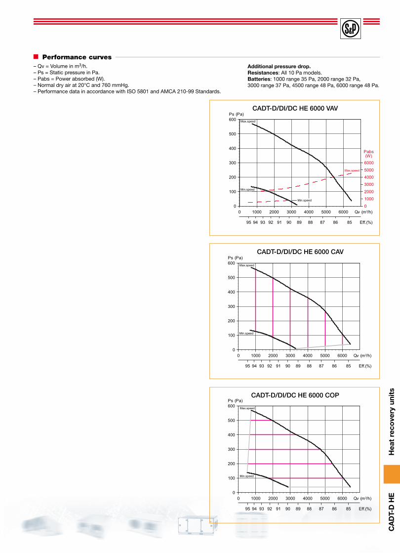
Performance curves
– Qv = Volume in m3/h.– Ps = Static pressure in Pa.– Pabs = Power absorbed (W).– Normal dry air at 20°C and 760 mmHg.– Performance data in accordance with ISO 5801 and AMCA 210-99 Standards.
Additional pressure drop.Resistances: All 10 Pa models.Batteries: 1000 range 35 Pa, 2000 range 32 Pa, 3000 range 37 Pa, 4500 range 48 Pa, 6000 range 48 Pa.
Hea
t re
cove
ry u
nits
CA
DT-
D H
E
0 1000 2000 3000 4000 5000 6000 Qv (m3/h)0
100
200
300
400
500
600Ps (Pa)
0
1000
2000
3000
4000
5000
6000
Pabs(W)
8586878889909192939495 Eff.(%)
Max.speed
Min.speed
Min.speed
Max.speed
0 1000 2000 3000 4000 5000 6000 Qv (m3/h)0
100
200
300
400
500
600Ps (Pa)
8586878889909192939495 Eff. (%)
Max.speed
Min.speed
0 1000 2000 3000 4000 5000 6000 Qv (m3/h)0
100
200
300
400
500
600Ps (Pa)
8586878889909192939495 Eff.(%)
Max.speed
Min.speed
CADT-D/DI/DC HE 6000 VAV
CADT-D/DI/DC HE 6000 CAV
CADT-D/DI/DC HE 6000 COP
Performance curves– Qv = Volume in m3/h.– Ps = Static pressure in Pa.– Pabs = Power absorbed (W).– Normal dry air at 20°C and 760 mmHg.– Performance data in accordance with ISO 5801 and AMCA 210-99 Standards.
Additional pressure drop.Resistances: All 10 Pa models.Batteries: 1000 range 35 Pa, 2000 range 32 Pa, 3000 range 37 Pa, 4500 range 48 Pa, 6000 range 48 Pa.

Hea
t re
cove
ry u
nits
CA
DT-
D H
E
Acoustic characteristics
lw, levels of sound transmitted in the "inlet" and "outlet" sound levels in accordance with regulation EN ISO 3747 regulation.
Sound transmitted
CADT-D/DI/DC HE 1000 125 250 500 1000 2000 4000 8000 dB(A)
LW VMAX 77 66 60 60 54 53 45 66
LW VMIN 62 52 49 47 39 35 26 52
Sound radiated
CADT-D/DI/DC HE 1000 125 250 500 1000 2000 4000 8000 dB(A)
LW VMAX 74 62 60 57 50 44 32 63
LW VMIN 60 50 43 42 34 26 17 48
Sound transmitted
CADT-D/DI/DC HE 2000 125 250 500 1000 2000 4000 8000 dB(A)
LW VMAX 70 63 62 63 58 54 44 66
LW VMIN 53 45 46 40 33 33 34 47
Sound radiated
CADT-D/DI/DC HE 2000 125 250 500 1000 2000 4000 8000 dB(A)
LW VMAX 66 59 58 58 52 46 32 62
LW VMIN 51 42 43 37 29 28 25 44
Sound transmitted
CADT-D/DI/DC HE 3000 125 250 500 1000 2000 4000 8000 dB(A)
LW VMAX 87 76 70 67 61 61 54 75
LW VMIN 72 61 57 55 49 46 39 61
Sound radiated
CADT-D/DI/DC HE 3000 125 250 500 1000 2000 4000 8000 dB(A)
LW VMAX 82 71 63 62 55 52 40 69
LW VMIN 68 57 51 49 42 37 24 56
Sound transmitted
CADT-D/DI/DC HE 4500 125 250 500 1000 2000 4000 8000 dB(A)
LW VMAX 82 76 70 69 63 64 55 75
LW VMIN 67 59 57 51 47 45 50 59
Sound radiated
CADT-D/DI/DC HE 4500 125 250 500 1000 2000 4000 8000 dB(A)
LW VMAX 78 70 64 63 57 56 42 69
LW VMIN 63 53 49 46 41 37 38 53
Sound transmitted
CADT-D/DI/DC HE 6000 125 250 500 1000 2000 4000 8000 dB(A)
LW VMAX 82 76 72 72 68 68 60 77
LW VMIN 67 61 59 53 50 47 45 60
Sound radiated
CADT-D/DI/DC HE 6000 125 250 500 1000 2000 4000 8000 dB(A)
LW VMAX 78 72 66 66 60 57 45 71
LW VMIN 62 54 50 47 44 37 33 54
Mounting accessories
TPP-D HE
External rain protection canopyModel External rain protection canopy
CADT-D/DI/DC HE 1000 TPP-D HE 1000
CADT-D/DI/DC HE 2000 TPP-D HE 2000
CADT-D/DI/DC HE 3000 TPP-D HE 3000
CADT-D/DI/DC HE 4500 TPP-D HE 4500
CADT-D/DI/DC HE 6000 TPP-D HE 6000
Model L P H
CADT-D/DI/DC HE 1000 2170 1170 95
CADT-D/DI/DC HE 2000 2170 1370 95
CADT-D/DI/DC HE 3000 2280 1680 110
CADT-D/DI/DC HE 4500 2530 1830 115
CADT-D/DI/DC HE 6000 2680 1980 125

Hea
t re
cove
ry u
nits
CA
DT-
D H
E
Model Electricalsupply
Power(W)
Voltage
(V)
IP CO2range(pm)
HR
(%)
DimensionsLxAxH(mm)
SCO2-G 0/10V 24VDC-24VAC
5 0-10Box IP65
Sensor IP200-2000
–80x238x80
SHT-G 0-100
Electrical accessoriesSCO2-A 0/10VAmbient CO2 and temperature sensorEnable control of the ventilation in ductworkaccording to the temperature and relativehumidity of the air circulating through it or to the temperature.
SCHT-ADAmbient CO2 sensor, temperature and relative humidity with displayEnable control of the ventilation ductworkaccording to the temperature and relativehumidity of the air circulating through it or to thetemperature.
SCO2-G 0/10VCO2 sensor probe for duct mountingEnable control of the ventilation in ductworkaccording to the CO2 concentration of the air circulating through it.
SHT-GTemperature and relative humidity sen-sor for duct mountingEnable control of the ventilation in ductworkaccording to the temperature and relativehumidity of the air circulating through it.
Model Electricalsupply
Power
(W)
Voltage Heightinst.
(m)
IP CO2range
(pm)
Tempe-raturerange(ºC)
HR
(%)
DimensionsLxAxH
(mm)
SCO2-A 0/10V 24VDC-24VAC
5 0-10 1,5-3,5 IP20 0-2000 0-50–
85x26x100SCHT-AD 0-100
Mounting accessories
AFRSpare filter.
ModelSpare filter
Spare filter G4 Spare filter F7 Spare filter F9
CADT-D/DI/DC HE 1000 AFR CADT HE 1000 G4 AFR CADT HE 1000 F7 AFR CADT HE 1000 F9
CADT-D/DI/DC HE 2000 AFR CADT HE 2000 G4 AFR CADT HE 2000 F7 AFR CADT HE 2000 F9
CADT-D/DI/DC HE 3000 AFR CADT HE 3000 G4 AFR CADT HE 3000 F7 AFR CADT HE 3000 F9
CADT-D/DI/DC HE 4500 AFR CADT HE 4500 G4 AFR CADT HE 4500 F7 AFR CADT HE 4500 F9
CADT-D/DI/DC HE 6000 AFR CADT HE 6000 G4 AFR CADT HE 6000 F7 AFR CADT HE 6000 F9
MSOFlexible coupling.
Model Flexible coupling
CADT-D/DI/DC HE 1000 MSO-250
CADT-D/DI/DC HE 2000 MSO-315
CADT-D/DI/DC HE 3000 MSO-400
CADT-D/DI/DC HE 4500 MSO-450
CADT-D/DI/DC HE 6000 MSO-450
SILSound attenuators to mount at the inlet and/or discharge of the heat recovery units.
Model Sound attenuator
CADT-D/DI/DC HE 1000 SIl-250
CADT-D/DI/DC HE 2000 SIl-315
CADT-D/DI/DC HE 3000 SIl-400
CADT-D/DI/DC HE 4500 SIl-450
CADT-D/DI/DC HE 6000 SIl-450
APCInlet/discharge protection guards.
Model Inlet/discharge protection guards
CADT-D/DI/DC HE 1000 APC-250
CADT-D/DI/DC HE 2000 APC-315
CADT-D/DI/DC HE 3000 APC-400
CADT-D/DI/DC HE 4500 APC-450
CADT-D/DI/DC HE 6000 APC-450

Hea
t re
cove
ry u
nits
CA
DT-
D H
E
Accessories for air treatment
BA-AF*External coil module for cold water.
* See complete information on the HEAT RECOVERY ACCESSORIES.
Model External coil module
CADT-D/DI/DC HE 1000 BA-AF 08
CADT-D/DI/DC HE 2000 BA-AF 18
CADT-D/DI/DC HE 3000 BA-AF 30*
CADT-D/DI/DC HE 4500 BA-AF 45
CADT-D/DI/DC HE 6000 BA-AF 56*
BA-AC*External coil module for hot water.
Model External coil module
CADT-D/DI/DC HE 1000 BA-AC 08
CADT-D/DI/DC HE 2000 BA-AC 18
CADT-D/DI/DC HE 3000 BA-AC 30*
CADT-D/DI/DC HE 4500 BA-AC 45
CADT-D/DI/DC HE 6000 BA-AC 56*
* The diameters do not match, you will need to apply a reduction in the duct.
* The diameters do not match, you will need to apply a reduction in the duct.