coules, h. e. (2013). contemporary approaches to …...4 figure 3: comparison of longitudinal...
TRANSCRIPT
Coules, H. E. (2013). Contemporary approaches to reducing weld inducedresidual stress. Materials Science and Technology, 29(1), 4-18.https://doi.org/10.1179/1743284712Y.0000000106
Peer reviewed version
Link to published version (if available):10.1179/1743284712Y.0000000106
Link to publication record in Explore Bristol ResearchPDF-document
This is the author accepted manuscript (AAM). The final published version (version of record) is available onlinevia Taylor and Francis at http://www.tandfonline.com/doi/abs/10.1179/1743284712Y.0000000106. Please referto any applicable terms of use of the publisher.
University of Bristol - Explore Bristol ResearchGeneral rights
This document is made available in accordance with publisher policies. Please cite only the publishedversion using the reference above. Full terms of use are available:http://www.bristol.ac.uk/pure/about/ebr-terms

1
Contemporary approaches to reducing weld-induced residual stress H. E. Coules1 1 Welding Engineering Research Centre, Cranfield University, Cranfield, Bedfordshire, MK43 0AL,
United Kingdom
Abstract Self-equilibrating residual stresses may occur in materials in the absence of external loading due to
internal strain inhomogeneity. While favourable distributions of residual stress can bestow an object
with the appearance of superior material properties, most welding processes leave behind residual
stresses in particularly unfavourable patterns, causing a greater susceptibility to fracture-based
failure mechanisms and unintended deformation. Currently, heat treatment is the primary means of
removing these stresses, but since the formation of residual stress is dependent upon many material
and process factors, there are several other viable mechanisms (using thermal, mechanical or phase
transformation effects) by which it may be modified. It is only now, using relevant advances in
numerical and experimental methods, that these techniques are being fully explored. This article
gives a brief introduction to weld-induced residual stresses and reviews the current state-of-the-art
with regard to their reduction. Emphasis is placed on the recent development of unconventional
techniques, and the mechanisms by which they act.
Keywords: Welding, residual stress, residual distortion, stress relief.
Introduction Macro-scale residual stresses, which equilibrate internally over a component or assembly, are
ubiquitous in everyday life. They allow tempered glass to resist fracture by inhibiting the
propagation of cracks at the material’s surface. They keep common fasteners such as nails and
screws from slipping free by exerting a contact force at the interface of the different components.
They even act within our own bodies to brace our arteries against the pressure of our blood1.
However, adverse distributions of residual stress in engineering components (specifically, high
tensile stresses in areas prone to fracture or fatigue), can lead to unexpected or premature failure
[1]. The formation and relaxation of residual stresses during manufacturing processes also causes
unwanted and problematic deformation which can be costly to correct. The large amount of non-
uniform heat input inherent in most forms of welding generates characteristic distributions of
residual stress which tend to have particularly adverse mechanical effects. This makes welding a
frequent cause of residual stress problems in engineering practice.
Broadly, residual stresses can be categorised into three groups based on scale [2]. Type I stresses,
which exist in the macro- scale, are most frequently of concern to engineers [3]. In polycrystalline
materials, inter-granular scale Type II stresses are generated by mechanical incompatibility between
adjacent crystallites [4]. Type III stresses, on the inter-atomic scale, result from crystallographic
defects [3, 5, 6]. With the greatest immediate implications for engineering design, only Type I
stresses resulting from welding process will be discussed here.
1 Mammalian arteries have been shown to contain circumferential residual stresses which are compressive at the inner arterial wall, and tensile at the outer wall. This is believed to make the total distribution of stress in the artery more uniform when the vessel is internally pressurised in vivo [163].

2
Formation of residual stresses during welding
Due to their widespread occurrence and notorious effects, weld-induced stresses are the
prototypical example of detrimental residual stress in structural materials. The formation of residual
stresses during welding is a consequence of the fact that different parts of a welded object
experience different cycles of thermal expansion and contraction. The resulting thermal stress
causes a non-uniform distribution of irreversible material deformation, and some of this
deformation remains after the material has cooled, resulting in an internal and completely self-
equilibrating stress field.
Residual stress formation during welding is illustrated schematically in Figure 1. Most forms of
welding require a large amount of localised heat input at the joint interface to achieve material
bonding, which occurs by mixing in a liquid or partially-melted state, or by solid-phase diffusion2 [7].
Inevitably this elevated temperature causes thermal dilation of material, accompanied by a gradual
decrease in yield strength and eventually, in the case in fusion welding, melting. By contrast,
material remote from the weld seam remains at a relatively low temperature throughout (see
Section B-B in Figure 1). The heated material at the interface then begins to cool, and any liquid
metal solidifies. The material then cools and contracts as a solid, but is mechanically constrained by
the surrounding cold material (Section C-C). This results in a characteristic distribution of residual
stress, with very large tensile stresses in the region of the joint (where material is prevented from
contracting as much as it otherwise would) which are balanced by compressive stresses elsewhere
[5, 8, 9].
Figure 1: The process of residual stress formation in a weld [10].
The exact magnitude and orientation of the resultant residual stresses depends on the direction of
the greatest thermal gradients encountered as the material cools, and on the mechanical constraint
2 Welding processes which involve complete melting of some part of the material are known under the umbrella term of ‘fusion welding’. This encompasses most common welding methods, but excludes solid-state processes such as linear friction welding and diffusion bonding.
3
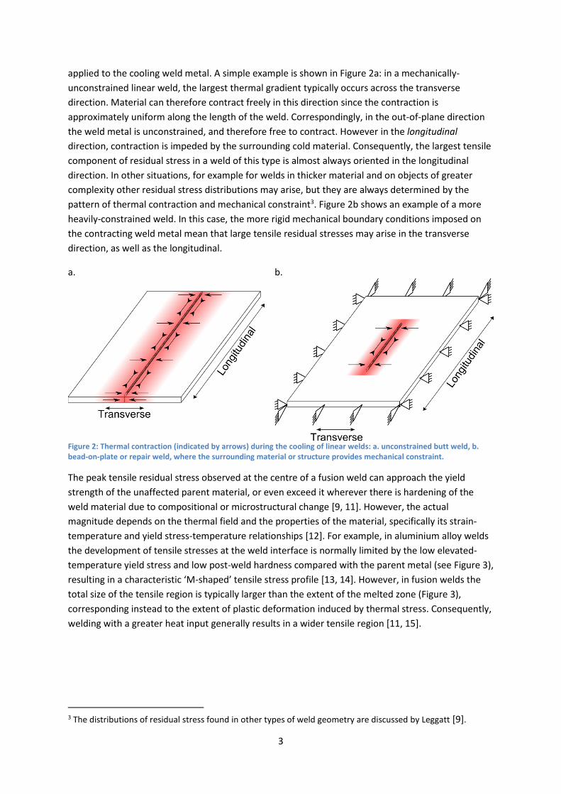
applied to the cooling weld metal. A simple example is shown in Figure 2a: in a mechanically-
unconstrained linear weld, the largest thermal gradient typically occurs across the transverse
direction. Material can therefore contract freely in this direction since the contraction is
approximately uniform along the length of the weld. Correspondingly, in the out-of-plane direction
the weld metal is unconstrained, and therefore free to contract. However in the longitudinal
direction, contraction is impeded by the surrounding cold material. Consequently, the largest tensile
component of residual stress in a weld of this type is almost always oriented in the longitudinal
direction. In other situations, for example for welds in thicker material and on objects of greater
complexity other residual stress distributions may arise, but they are always determined by the
pattern of thermal contraction and mechanical constraint3. Figure 2b shows an example of a more
heavily-constrained weld. In this case, the more rigid mechanical boundary conditions imposed on
the contracting weld metal mean that large tensile residual stresses may arise in the transverse
direction, as well as the longitudinal.
a.
b.
Figure 2: Thermal contraction (indicated by arrows) during the cooling of linear welds: a. unconstrained butt weld, b. bead-on-plate or repair weld, where the surrounding material or structure provides mechanical constraint.
The peak tensile residual stress observed at the centre of a fusion weld can approach the yield
strength of the unaffected parent material, or even exceed it wherever there is hardening of the
weld material due to compositional or microstructural change [9, 11]. However, the actual
magnitude depends on the thermal field and the properties of the material, specifically its strain-
temperature and yield stress-temperature relationships [12]. For example, in aluminium alloy welds
the development of tensile stresses at the weld interface is normally limited by the low elevated-
temperature yield stress and low post-weld hardness compared with the parent metal (see Figure 3),
resulting in a characteristic ‘M-shaped’ tensile stress profile [13, 14]. However, in fusion welds the
total size of the tensile region is typically larger than the extent of the melted zone (Figure 3),
corresponding instead to the extent of plastic deformation induced by thermal stress. Consequently,
welding with a greater heat input generally results in a wider tensile region [11, 15].
3 The distributions of residual stress found in other types of weld geometry are discussed by Leggatt [9].

4
Figure 3: Comparison of longitudinal residual stress (measured using neutron diffraction) and hardness in a gas metal arc weld in 2024 aluminium alloy. Widths of the weld fusion zone (FZ), near heat-affected zone (NHAZ), far heat-affected zone (FHAZ) are indicated. The magnitude of the residual stress in the weld is limited by the variation in yield strength brought about by the thermal effects of welding [16].
While simple in concept, residual stress formation in welds is quite difficult to predict quantitatively.
The main problem is that since the process includes coupled thermal and mechanical components,
the number of input variables involved is large [17]. A list of factors affecting residual stress would
include: the geometry of the welded object, its thermal history, its (temperature-dependent)
material properties, its phase transformations and metallurgical phenomena, and its mechanical
boundary conditions. Over the last forty years, researchers have used numerical models of
increasing complexity to study the process. Today, the use of the finite element method is dominant
and modelling of welding residual stresses can be considered a relatively mature field, which finds
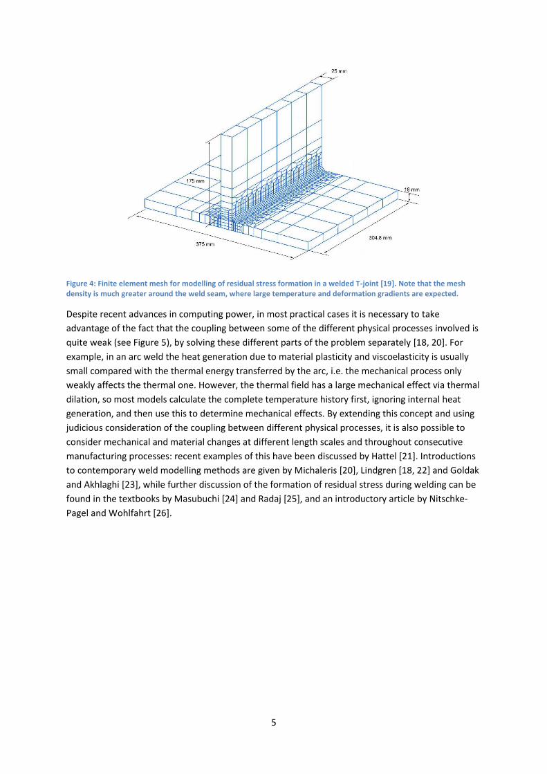
substantial industrial application [18]. An example finite element mesh for a welded object is shown
in Figure 4.
5
Figure 4: Finite element mesh for modelling of residual stress formation in a welded T-joint [19]. Note that the mesh density is much greater around the weld seam, where large temperature and deformation gradients are expected.
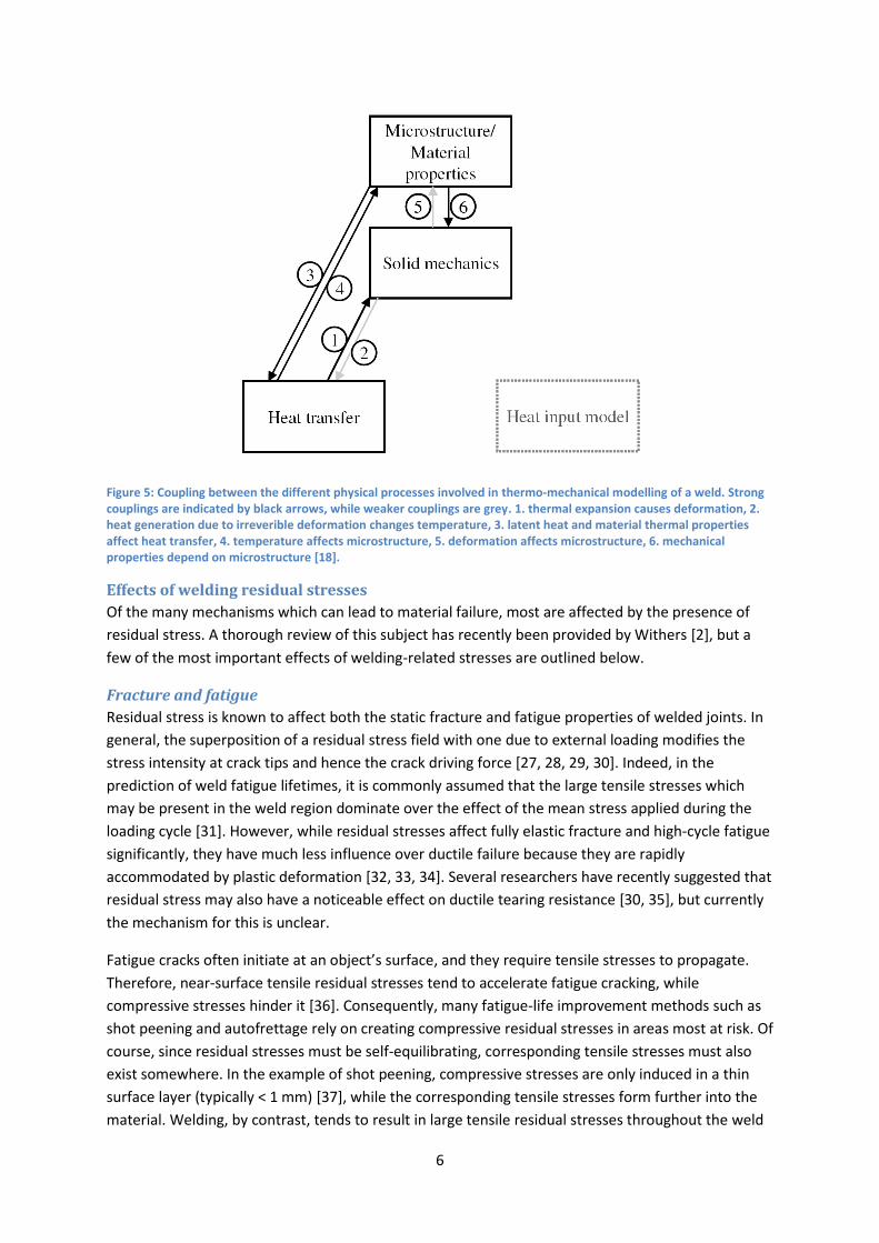
Despite recent advances in computing power, in most practical cases it is necessary to take
advantage of the fact that the coupling between some of the different physical processes involved is
quite weak (see Figure 5), by solving these different parts of the problem separately [18, 20]. For
example, in an arc weld the heat generation due to material plasticity and viscoelasticity is usually
small compared with the thermal energy transferred by the arc, i.e. the mechanical process only
weakly affects the thermal one. However, the thermal field has a large mechanical effect via thermal
dilation, so most models calculate the complete temperature history first, ignoring internal heat
generation, and then use this to determine mechanical effects. By extending this concept and using
judicious consideration of the coupling between different physical processes, it is also possible to
consider mechanical and material changes at different length scales and throughout consecutive
manufacturing processes: recent examples of this have been discussed by Hattel [21]. Introductions
to contemporary weld modelling methods are given by Michaleris [20], Lindgren [18, 22] and Goldak
and Akhlaghi [23], while further discussion of the formation of residual stress during welding can be
found in the textbooks by Masubuchi [24] and Radaj [25], and an introductory article by Nitschke-
Pagel and Wohlfahrt [26].
6
Figure 5: Coupling between the different physical processes involved in thermo-mechanical modelling of a weld. Strong couplings are indicated by black arrows, while weaker couplings are grey. 1. thermal expansion causes deformation, 2. heat generation due to irreverible deformation changes temperature, 3. latent heat and material thermal properties affect heat transfer, 4. temperature affects microstructure, 5. deformation affects microstructure, 6. mechanical properties depend on microstructure [18].
Effects of welding residual stresses
Of the many mechanisms which can lead to material failure, most are affected by the presence of
residual stress. A thorough review of this subject has recently been provided by Withers [2], but a
few of the most important effects of welding-related stresses are outlined below.
Fracture and fatigue
Residual stress is known to affect both the static fracture and fatigue properties of welded joints. In
general, the superposition of a residual stress field with one due to external loading modifies the
stress intensity at crack tips and hence the crack driving force [27, 28, 29, 30]. Indeed, in the
prediction of weld fatigue lifetimes, it is commonly assumed that the large tensile stresses which
may be present in the weld region dominate over the effect of the mean stress applied during the
loading cycle [31]. However, while residual stresses affect fully elastic fracture and high-cycle fatigue
significantly, they have much less influence over ductile failure because they are rapidly
accommodated by plastic deformation [32, 33, 34]. Several researchers have recently suggested that
residual stress may also have a noticeable effect on ductile tearing resistance [30, 35], but currently
the mechanism for this is unclear.
Fatigue cracks often initiate at an object’s surface, and they require tensile stresses to propagate.
Therefore, near-surface tensile residual stresses tend to accelerate fatigue cracking, while
compressive stresses hinder it [36]. Consequently, many fatigue-life improvement methods such as
shot peening and autofrettage rely on creating compressive residual stresses in areas most at risk. Of
course, since residual stresses must be self-equilibrating, corresponding tensile stresses must also
exist somewhere. In the example of shot peening, compressive stresses are only induced in a thin
surface layer (typically < 1 mm) [37], while the corresponding tensile stresses form further into the
material. Welding, by contrast, tends to result in large tensile residual stresses throughout the weld

7
thickness, which equilibrate with opposing stresses situated further away from the joint [38]. As a
result of this, both methods which induce compressive surface stresses and methods which reduce
stresses through the entire weld thickness may be used to improve fatigue life of welds.
As well as causing residual stresses, welding also causes microstructural change and geometric stress
concentrations [39, 40, 41]. Both of these factors can also affect fatigue, which complicates the
study of welding residual stresses with respect to fatigue life [42, 43]. Furthermore, residual stress
distributions can themselves be changed by in-service loading conditions, generally by yielding
during the first loading cycle [36, 44].
Stress corrosion cracking
Stress-corrosion cracking (SCC) is a form of environmentally-assisted material failure which occurs
when the combined effect of chemical and mechanical driving forces causes gradual crack
propagation throughout the affected material [45]. Since both chemical and mechanical factors are
involved, only materials exposed to particular corrosive environments while under mechanical stress
are susceptible to SCC. The residual stresses left behind by welding are often sufficient to initiate
SCC in areas where it would not otherwise occur due to the lack of a sufficient mechanical driving
force [46]. Furthermore, welding can also cause geometric stress concentrations and increased
metallurgical susceptibility to corrosion [47], so SCC frequently initiates at welded joints. This causes
serious problems in applications (such as gas pipelines and nuclear reactor components) where
welded parts are used in a corrosive environment [48, 49], often necessitating costly inspection
programmes to prevent this ‘insidious’ form of failure.
Distortion
By definition, the residual stress field within an object is internally self-equilibrating. For a stress
distribution to exist in the absence of any externally-applied force or temperature differential, there
must be an internal incompatibility in strain4 [50, 51]. Therefore, when residual stress is added or
relaxed during any manufacturing process, there must also be a corresponding inhomogeneous
deformation. Residual stresses due to welding, for example, are associated with strains which when
accumulated along the length of a weld seam, can often cause visible warping of a welded object.
This distortion is by far the most evident and frequently the most problematic effect of residual
stress. Small residual strains due to plastic deformation at the weld seam cause different modes of
distortion, originally categorised by Masubuchi [24], depending on the weld and object geometry. In
addition to shrinkage and bending-type distortion modes, welds in thin-walled structures often
produce residual stresses large enough to cause buckling, which can complicate distortion analysis
and prediction [52].
The implications of welding distortion for manufacturing (aside from those related to other effects of
residual stress) are of great practical concern [53, 54], and have led to the development of a host of
techniques specifically to prevent distortion, without aiming to remediate the underlying residual
stress. These include bending-back of distorted weldments, presetting [55], control of mechanical
constraint [56, 57, 58], control of weld sequencing [53, 59, 60], and flame straightening. An example
of the effects of varying mechanical constraint is shown in Figure 6, and such methods of distortion
control are discussed further by Conrardy and Dull [61] and Masubuchi [24].
4 This incompatibility is variously referred to by researchers as ‘eigenstrain’, ‘inherent strain’ and ‘misfit strain’.

8
a. b. Figure 6: Predicted distortion of a dual-phase steel overlap weld with clamping released a. immediately after welding, b. once the weld has cooled to room temperature. Out-of-plane displacements magnified 50x [62].
Measurement
Techniques for measuring residual stress have been recently discussed by Rossini et al. [63] and
Withers et al. [64], but briefly, three fundamental strategies exist:
1. Measuring the change in strain as residual stresses are relaxed by removal or cutting of
material.
2. Measuring the inter-atomic spacing and comparing this to the spacing in an unstressed
reference specimen.
3. Measuring the change in another physical phenomenon with which stress interacts.
Practical implementations of the first option include the hole-drilling method, in which stresses are
back-calculated from strain measurements made near a small hole as it is drilled [65, 66], and the
contour method [67], where accurate measurement of the profile of a cut face is used to reconstruct
a map of the residual stresses before cutting. Of course, all such ‘relaxation’ methods are at least
partially destructive to the sample; such techniques are the subject of a recent review by Schajer
[68]. The second option is possible because the inter-atomic spacing in a crystalline material changes
in response to applied stress – a fact which is reflected in the elastic strain response of the bulk
material. Therefore, by using x-ray or neutron diffraction to measure the crystal lattice-spacing,
strain can be measured non-destructively in (polycrystalline) metals and ceramics, and from this the
stress state can be calculated. For the final method, it is possible to use changes in the sonic and
magnetic properties of some materials to measure stress. For example, the configuration of
magnetic domains in ferromagnetic materials is sensitive to stress, and so residual stresses can be
inferred from (calibrated) measurements of magnetic Barkhausen noise [69]. However, the effect of
residual stress on these properties is not well understood and is often relatively weak in comparison
to the effect of other factors (eg. microstructure), so these techniques are normally used only for
comparative measurements [1].
To measure residual stresses produced by welding, diffraction using neutrons or high-energy
synchrotron x-rays is currently favoured by researchers. These methods have been developed to a
point of practical and quantifiable accuracy, and can be used at a range of spatial resolutions
conducive to the study of engineering structures. Furthermore, usable quantities of neutron or
synchrotron radiation can penetrate deeply (in the order of tens of mm) into most common metals,
and can therefore be used for measurement at locations which cannot be probed by other means
(see Figure 7). Unfortunately, these methods can only be performed at a small number of neutron

9
and synchrotron facilities, and are therefore not suitable for common use in industry. Neutron
techniques are discussed by Krawitz [70] and Withers [2], and synchrotron diffraction by Reimers et
al. [71]. Diffraction of lower-energy x-rays (produced using conventional x-ray tubes [72]) is more
widely used due to its accessibility and relative accuracy. However, a major drawback is that the
penetration depth of this radiation is low, and so only stresses close to the surface of the material
(conventionally, within a few tens of microns) may be measured.
Figure 7: Approximate capabilities, in terms of spatial resolution and penetration depth, of different residual measurement techniques [64].
Reduction of welding residual stresses
Overview
A wide variety of techniques are available for the reduction or modification of residual stress
distributions in bulk materials. Some of these, such as annealing and peening processes have been
adapted or optimised for use on welded joints. However, there also exist welding-specific methods
such as in-process cooling and Global Mechanical Tensioning (GMT), which are designed to work
against the particular thermal strain mechanism of residual stress formation which exists in welding,
or against the particular distributions of residual stress which welding produces. These methods
have received increased attention over the past two decades, as researchers seek cheaper and more
effective alternatives to long-standing techniques.
To cause a change in the residual stress state in an object, a permanent plastic deformation must be
introduced, or the occurrence during welding of such a deformation must be influenced. This can be
done by using an externally-applied mechanical force, by the application or modification of a
thermal field, or by inducing a solid-state phase transformation. It is therefore possible to categorise
residual stress modification strategies into three broad groups based on these three mechanisms of
action. Here, welding residual stress mitigation methods have been further categorised into
‘conventional’ techniques, which currently see widespread application, and ‘advanced’ techniques
which are mainly at the experimental stage of development and not commonly encountered outside
of research. Additional reviews of the application of stress engineering techniques to welding can be

10
found in works by Radaj [25], Feng et al. [73], Withers [1], Williams and Steuwer [74], and Altenkirch
[75], while a helpful guide to early work on the topic from the USSR is provided by Pavlovsky and
Masubuchi [76].
Conventional thermal techniques
Post-weld heat treatment
Stress-relief annealing involves heating an object uniformly, normally to several hundred degrees
above ambient temperature, to allow residual stresses to relax automatically. Application of this
procedure to welded joints, which is known as Post-Weld Heat Treatment (PWHT), is a very
commonly accepted method of residual stress relief and has been shown to be effective for this
purpose under a wide range of circumstances [77, 78, 79, 80, 81]. Primarily, the reduction in yield
strength at high temperature causes the material to yield locally under its own internal stresses,
however it is also believed that in many cases additional deformation can be caused by creep and
recrystallisation [82, 83, 84]. After the stress has been relaxed, gradual and uniform cooling is used
to prevent subsequent stress formation. Depending on the material, sufficient stress-relief may take
place at below the temperature required for any change in microstructure, but typically diffusional
processes or even gross recrystallisation will also occur [1, 25]. Often this is a welcome side-effect; in
carbon-manganese steel weld zones containing brittle phases (particularly martensite) generated
during rapid cooling of the weld metal, tempering which occurs during PWHT can act to restore
fracture toughness.
Though it is effective at reducing residual stress in most bulk metals, PWHT is not universally
applicable. For example, PWHT is not normally applied to precipitation-hardening alloys due to the
risk of over-aging the parent metal5: temperature-controlled diffusion acts to coarsen the precipitate
distribution, reducing the precipitate’s effectiveness at impeding dislocation movement. Likewise, in
dissimilar-material welds, mismatch between different thermal expansion coefficients can cause
PWHT to be ineffective, or even detrimental [85, 21]. The application of PWHT can also cause a form
of brittle failure known as stress-relief cracking or reheat cracking, in which thermally-induced
embrittlement leads to cracking as high-temperature yielding or inter-granular creep occurs [86].
Finally, the process becomes both expensive and time-consuming when large components are
involved.
Control of heat input during welding
The energy input per unit length of weld made obviously has a pronounced effect on the distribution
of temperature in the material [87]. This can in turn affect both the weld microstructure and the
formation of residual stresses. Unfortunately, the need for a sufficient temperature at the joint
interface to allow material bonding puts a practical limit on the amount by which heat input can be
reduced. The heat input is further constrained by factors relating to the welding process itself: in
laser welding for example, reducing the heat input will eventually cause transition of the process
from keyhole to conduction mode6. Therefore, control of welding heat input can never completely
5 The weld itself and the surrounding heat-affected zone will typically be over-aged anyway after the welding thermal cycle. 6 There are normally considered to be two distinct modes of laser welding. In keyhole mode, continual vaporisation opens a ‘keyhole’ in the material, which allows a very deep and thin weld cross-section. In conduction mode, material vaporisation is insufficient to sustain a keyhole, resulting in a wide and shallow weld [164].
11
prevent residual stresses from forming, but it can reduce the width over which plastic strain (and
hence tensile residual stress) occurs [11, 15].
Uniform preheating of the weld region is widely employed to reduce the large thermal gradient
necessary to enable fusion at the weld interface, which is the cause of three common problems: ‘hot
cracking’ (thermal fracture which can occur during the welding of brittle materials), the formation of
brittle martensite due to rapid cooling of the weld material, and residual stress. Preheating the weld
region may also be used to dry the surface of the material, which is sometimes necessary to prevent
hydrogen embrittlement - a common symptom of excessive hydrogen absorption in high-strength
steel welds [88]. However, due to the decreased yield strength of the parent material at elevated
temperature, preheating can also allow increased plastic deformation, having a detrimental effect
on residual stress [89]. Therefore, though it may reduce residual stresses in some material/thermal
cycle combinations, preheat cannot be considered a universally effective method of residual stress
control.
Conventional mechanical techniques
Peening
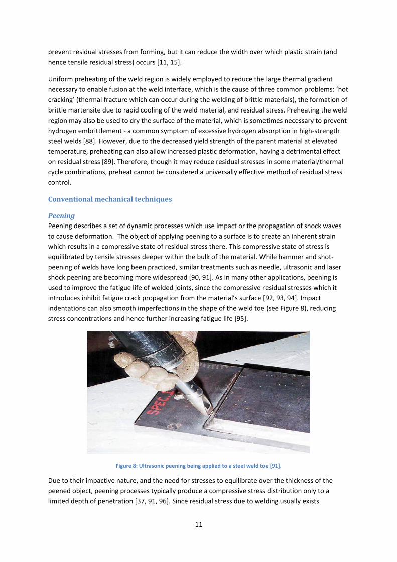
Peening describes a set of dynamic processes which use impact or the propagation of shock waves
to cause deformation. The object of applying peening to a surface is to create an inherent strain
which results in a compressive state of residual stress there. This compressive state of stress is
equilibrated by tensile stresses deeper within the bulk of the material. While hammer and shot-
peening of welds have long been practiced, similar treatments such as needle, ultrasonic and laser
shock peening are becoming more widespread [90, 91]. As in many other applications, peening is
used to improve the fatigue life of welded joints, since the compressive residual stresses which it
introduces inhibit fatigue crack propagation from the material’s surface [92, 93, 94]. Impact
indentations can also smooth imperfections in the shape of the weld toe (see Figure 8), reducing
stress concentrations and hence further increasing fatigue life [95].
Figure 8: Ultrasonic peening being applied to a steel weld toe [91].
Due to their impactive nature, and the need for stresses to equilibrate over the thickness of the
peened object, peening processes typically produce a compressive stress distribution only to a
limited depth of penetration [37, 91, 96]. Since residual stress due to welding usually exists

12
throughout the thickness of the joined material, peening cannot normally be said to remove welding
residual stresses but rather to superimpose an additional, protective residual stress distribution.
Consequently, peening does not protect against crack propagation from internal defects, and
residual stress which exists deeper in the material may still cause distortion of the welded object.
Vibratory stress relief
The difficulty and cost involved in applying PWHT, especially to large assemblies and castings, led to
the development of Vibratory Stress Relief (VSR) during the Second World War [97]. In this method,
the welded object is simply vibrated strongly using motorised or electromagnetic equipment.
Despite many years of research, there is still disagreement over the fundamental mechanism by
which this acts to reduce stresses, or indeed whether it has any significant effect at all [98, 99]. It has
been proposed that VSR provides a driving force for dislocation movement at the intra-granular level
[100], or even that it initiates a martensitic transformation in steels [101]. However currently the
most widespread view is that under some conditions, VSR is able to cause local plastic deformation
in the regions of material which, due to the presence of residual stress, are already close to their
yield point. This theory explains both the gradual nature (i.e. occurring over many vibration cycles)
of observed strain changes, and the apparent presence of a critical vibration amplitude, under which
no stress relief will occur [102, 103, 104]. One implication of this idea is that cyclic plasticity occurs
during the process, which might negatively impact the subsequent fatigue lifetime of any treated
component. Despite recent advances in residual stress measurement techniques there is still a lack
of published data on the topic of VSR, and so although VSR has many industrial users its efficacy and
theoretical basis remain controversial.
Advanced thermal techniques
Localised cooling
By manipulating the distribution of temperature in a component as it is welded, localised cooling
aims to modify or generally reduce the final pattern of residual stress. The earliest experiments were
carried out in the 1960s in support of NASA’s Saturn programme [105]. Although several cooling
arrangements have been suggested, most modern experimenters have used an intense heat sink
trailing the welding heat source to create a characteristic valley-shaped temperature distribution7
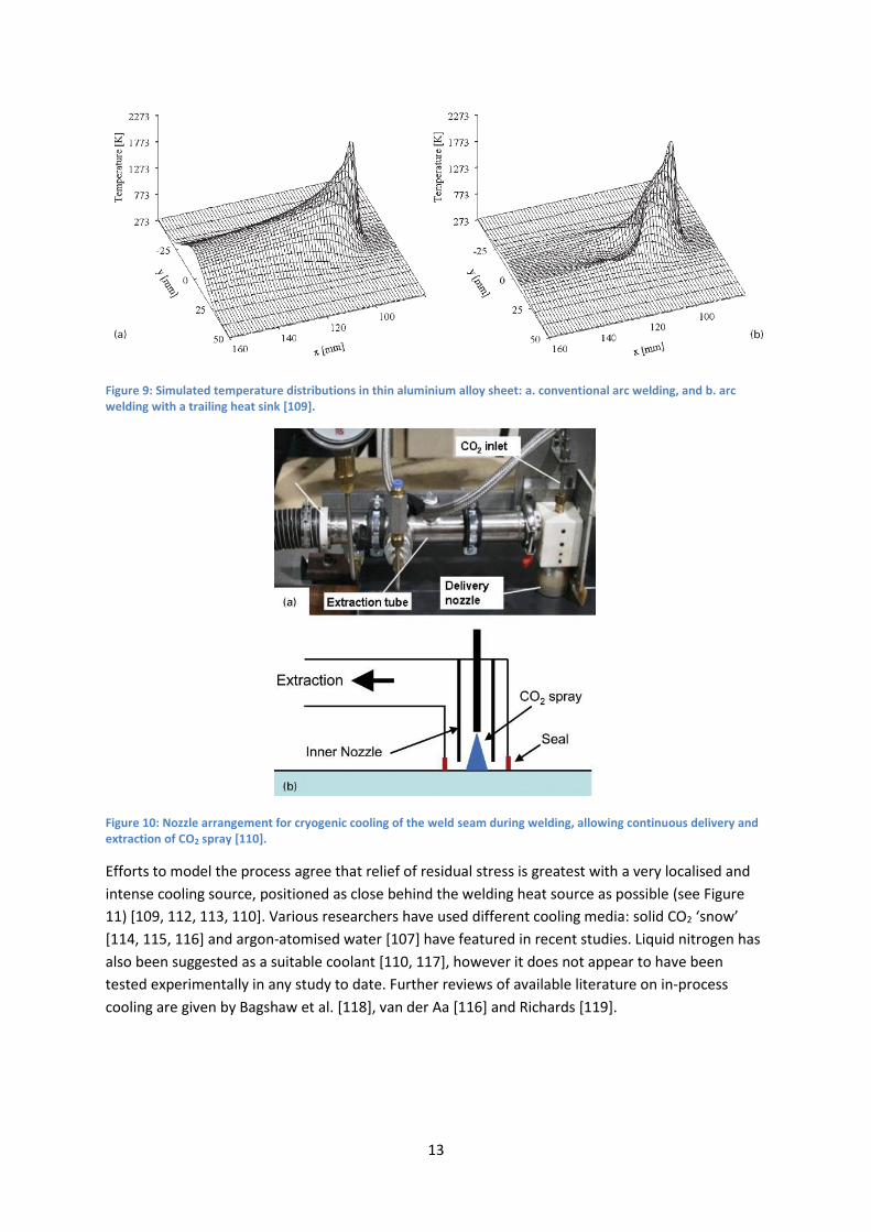
[106, 107, 108, 109, 110], shown in Figure 9. An example of a cooling device designed to achieve this
is shown in Figure 10. Guan et al. [111] originally proposed that this can prevent the formation of a
single wide region of tensile residual stress at the weld line, instead creating a more complex
distribution of stress consisting of several local maxima and minima. The mechanism of thermal
strain by which this comes about was subsequently explained by van der Aa et al. [109] and Richards
et al. [110], using numerical modelling.
7 Following the convention of Guan et al. [165], this process is alternatively referred to as Low Stress No Distortion (LSND) welding.
13
Figure 9: Simulated temperature distributions in thin aluminium alloy sheet: a. conventional arc welding, and b. arc welding with a trailing heat sink [109].
Figure 10: Nozzle arrangement for cryogenic cooling of the weld seam during welding, allowing continuous delivery and extraction of CO2 spray [110].
Efforts to model the process agree that relief of residual stress is greatest with a very localised and
intense cooling source, positioned as close behind the welding heat source as possible (see Figure
11) [109, 112, 113, 110]. Various researchers have used different cooling media: solid CO2 ‘snow’
[114, 115, 116] and argon-atomised water [107] have featured in recent studies. Liquid nitrogen has
also been suggested as a suitable coolant [110, 117], however it does not appear to have been
tested experimentally in any study to date. Further reviews of available literature on in-process
cooling are given by Bagshaw et al. [118], van der Aa [116] and Richards [119].

14
a.
b.
c. Figure 11: Effect of cooling source position on stress development during friction stir welding of aluminium alloy with localised cooling: a. no cooling, b. trailing the welding tool by 40 mm, c. trailing by 20 mm. The black line with squares represents the longitudinal component of stress, the solid red line is the transverse component, and the dashed blue line is the von Mises stress [110].
Localised heating
As with localised cooling, a number of schemes of in-process heating have been investigated, with
the intention of modifying the stress distribution in the vicinity of the welding heat source [120,
121]. Most researchers describe how the process creates a tensile stress in the longitudinal direction
during welding8 [122, 123, 124]. The presence of a tensile stress during welding, and its subsequent
removal due to temperature equilibration, has a similar effect to GMT (see section on GMT below);
reducing the longitudinal strain misfit between the weld material and the parent metal. An
alternative mechanism was first investigated by Greene and Holzbaur, who pioneered this form of
stress-relieving during the latter part of the Second World War [125]. They used localised heating
adjacent to the weld after it had been completed to overstress the weld material - yielding it, and
removing the tensile residual stress (Figure 12c).
8 For this reason, localised heating methods are often alternatively described as ‘thermal tensioning’ by some authors.
15
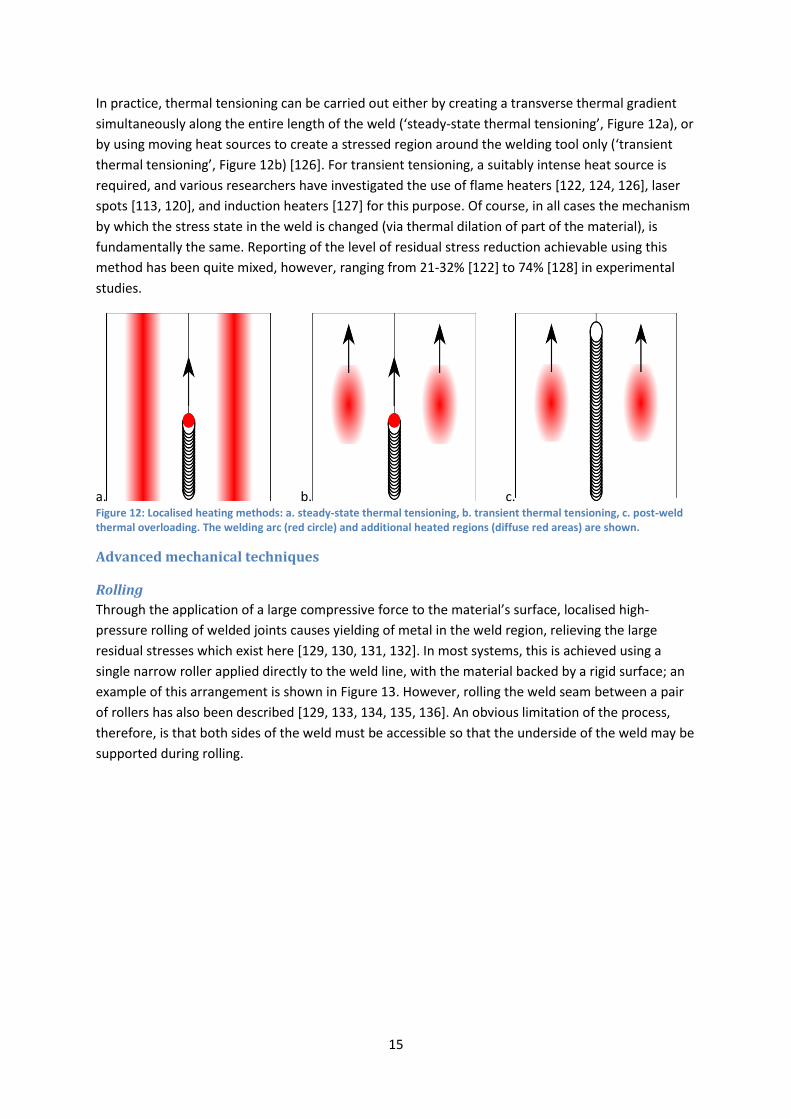
In practice, thermal tensioning can be carried out either by creating a transverse thermal gradient
simultaneously along the entire length of the weld (‘steady-state thermal tensioning’, Figure 12a), or
by using moving heat sources to create a stressed region around the welding tool only (‘transient
thermal tensioning’, Figure 12b) [126]. For transient tensioning, a suitably intense heat source is
required, and various researchers have investigated the use of flame heaters [122, 124, 126], laser
spots [113, 120], and induction heaters [127] for this purpose. Of course, in all cases the mechanism
by which the stress state in the weld is changed (via thermal dilation of part of the material), is
fundamentally the same. Reporting of the level of residual stress reduction achievable using this
method has been quite mixed, however, ranging from 21-32% [122] to 74% [128] in experimental
studies.
a. b. c. Figure 12: Localised heating methods: a. steady-state thermal tensioning, b. transient thermal tensioning, c. post-weld thermal overloading. The welding arc (red circle) and additional heated regions (diffuse red areas) are shown.
Advanced mechanical techniques
Rolling
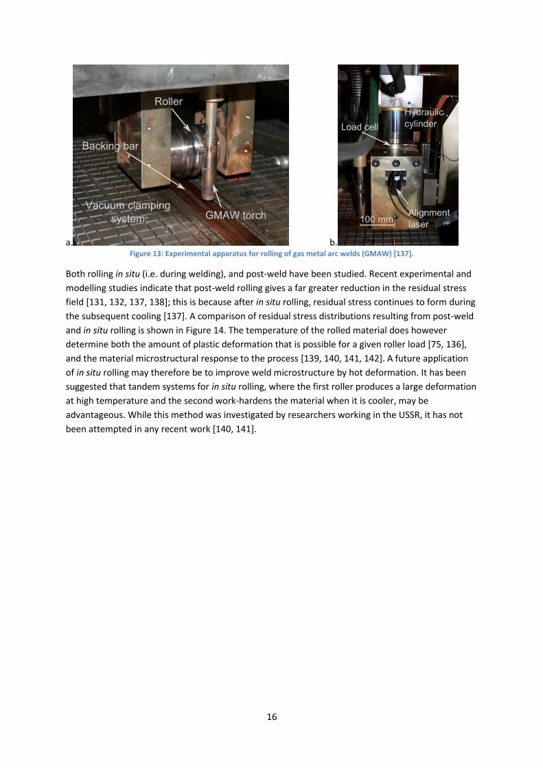
Through the application of a large compressive force to the material’s surface, localised high-
pressure rolling of welded joints causes yielding of metal in the weld region, relieving the large
residual stresses which exist here [129, 130, 131, 132]. In most systems, this is achieved using a
single narrow roller applied directly to the weld line, with the material backed by a rigid surface; an
example of this arrangement is shown in Figure 13. However, rolling the weld seam between a pair
of rollers has also been described [129, 133, 134, 135, 136]. An obvious limitation of the process,
therefore, is that both sides of the weld must be accessible so that the underside of the weld may be
supported during rolling.
16
a. b. Figure 13: Experimental apparatus for rolling of gas metal arc welds (GMAW) [137].
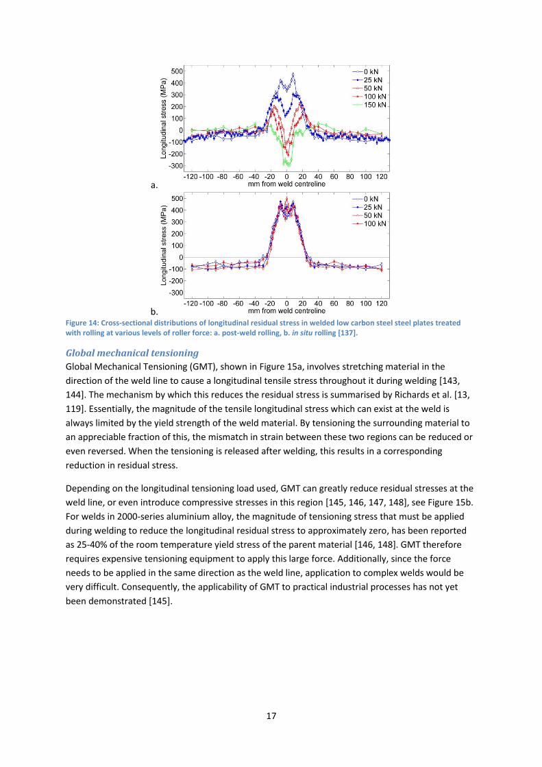
Both rolling in situ (i.e. during welding), and post-weld have been studied. Recent experimental and
modelling studies indicate that post-weld rolling gives a far greater reduction in the residual stress
field [131, 132, 137, 138]; this is because after in situ rolling, residual stress continues to form during
the subsequent cooling [137]. A comparison of residual stress distributions resulting from post-weld
and in situ rolling is shown in Figure 14. The temperature of the rolled material does however
determine both the amount of plastic deformation that is possible for a given roller load [75, 136],
and the material microstructural response to the process [139, 140, 141, 142]. A future application
of in situ rolling may therefore be to improve weld microstructure by hot deformation. It has been
suggested that tandem systems for in situ rolling, where the first roller produces a large deformation
at high temperature and the second work-hardens the material when it is cooler, may be
advantageous. While this method was investigated by researchers working in the USSR, it has not
been attempted in any recent work [140, 141].
17
a.
b. Figure 14: Cross-sectional distributions of longitudinal residual stress in welded low carbon steel steel plates treated with rolling at various levels of roller force: a. post-weld rolling, b. in situ rolling [137].
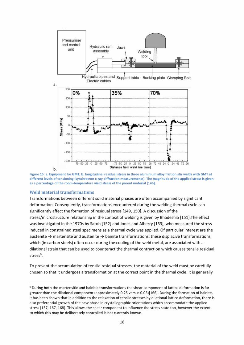
Global mechanical tensioning
Global Mechanical Tensioning (GMT), shown in Figure 15a, involves stretching material in the
direction of the weld line to cause a longitudinal tensile stress throughout it during welding [143,
144]. The mechanism by which this reduces the residual stress is summarised by Richards et al. [13,
119]. Essentially, the magnitude of the tensile longitudinal stress which can exist at the weld is
always limited by the yield strength of the weld material. By tensioning the surrounding material to
an appreciable fraction of this, the mismatch in strain between these two regions can be reduced or
even reversed. When the tensioning is released after welding, this results in a corresponding
reduction in residual stress.
Depending on the longitudinal tensioning load used, GMT can greatly reduce residual stresses at the
weld line, or even introduce compressive stresses in this region [145, 146, 147, 148], see Figure 15b.
For welds in 2000-series aluminium alloy, the magnitude of tensioning stress that must be applied
during welding to reduce the longitudinal residual stress to approximately zero, has been reported
as 25-40% of the room temperature yield stress of the parent material [146, 148]. GMT therefore
requires expensive tensioning equipment to apply this large force. Additionally, since the force
needs to be applied in the same direction as the weld line, application to complex welds would be
very difficult. Consequently, the applicability of GMT to practical industrial processes has not yet
been demonstrated [145].
18
a.
b. Figure 15: a. Equipment for GMT, b. longitudinal residual stress in three aluminium alloy friction stir welds with GMT at different levels of tensioning (synchrotron x-ray diffraction measurements). The magnitude of the applied stress is given as a percentage of the room-temperature yield stress of the parent material [146].
Weld material transformations
Transformations between different solid material phases are often accompanied by significant
deformation. Consequently, transformations encountered during the welding thermal cycle can
significantly affect the formation of residual stress [149, 150]. A discussion of the
stress/microstructure relationship in the context of welding is given by Bhadeshia [151].The effect
was investigated in the 1970s by Satoh [152] and Jones and Alberry [153], who measured the stress
induced in constrained steel specimens as a thermal cycle was applied. Of particular interest are the
austenite → martensite and austenite → bainite transformations; these displacive transformations,
which (in carbon steels) often occur during the cooling of the weld metal, are associated with a
dilational strain that can be used to counteract the thermal contraction which causes tensile residual
stress9.
To prevent the accumulation of tensile residual stresses, the material of the weld must be carefully
chosen so that it undergoes a transformation at the correct point in the thermal cycle. It is generally
9 During both the martensitic and bainitic transformations the shear component of lattice deformation is far greater than the dilational component (approximately 0.25 versus 0.03)[166]. During the formation of bainite, it has been shown that in addition to the relaxation of tensile stresses by dilational lattice deformation, there is also preferential growth of the new phase in crystallographic orientations which accommodate the applied stress [157, 167, 168]. This allows the shear component to influence the stress state too, however the extent to which this may be deliberately controlled is not currently known.

19
taken that the transformation should occur at a temperature low enough to preclude subsequent
build-up of stress, but should be complete by the time the metal cools to room temperature10 [154,
155]. Figure 16 shows schematically the effect of different phase transformations on the build-up of
stress in uniaxially-constrained steel specimens as they are cooled from 1000°C. The austenite →
ferrite transformation (a) takes place a too high a temperature to have a great effect on the residual
stress: thermal contraction continues after the transformation, and the tensile stress resulting from
this saturates at the yield strength of the material. On the other hand, lines (b) and (c) show the
effect of bainitic or martensitic transformations taking place at a lower temperature. In both cases,
while the transformation is complete by the time the material has cooled to room temperature,
varying the transformation temperature affects how much thermal contraction can occur
subsequent to transformation.
Figure 16: Thermal stress development during the cooling of axially-constrained specimens of different steels: a. is ferritic-pearlitic, whereas b. and c. exhibit bainitic or martensitic transformations (from Francis et al. 2007 [46], after Nitschke-Pagel and Wohlfahrt 2002 [26]).
Since the majority of common welding processes involve the addition of filler material at the joint
interface, there is an opportunity to take advantage of transformation effects at the interface only,
without changing the material used for the rest of the welded structure. Recently, there has been a
concerted effort to design weld filler metals which reduce residual stress while maintaining
acceptable mechanical properties. Most researchers have concentrated on the martensitic
transformation, using additional carbon and/or a combination of nickel and chromium (in quantities
up to about 15 wt% each) to reduce the temperature at which martensite begins to form [156, 157,
10 Although an incomplete martensitic transformation is not necessarily detrimental to the residual stress state, large amounts of untransformed austenite could seriously reduce the material’s mechanical properties [169].

20
158]. Unfortunately, the increased carbon content and presence of brittle martensite can give low-
transformation-temperature weld material reduced impact toughness [155]. Therefore, while the
effectiveness of this approach for reducing residual stresses has been demonstrated in several
studies [155, 157], further research is needed to simultaneously achieve excellent mechanical
properties. A final important limitation of low transformation temperature materials is that they can
undergo significant transformation strain when reheated, the effects of which would have to be
carefully considered if such materials were ever to be used in elevated-temperature service.
Discussion
Mechanisms of stress reduction
The fundamental physical phenomena (such as thermal transport, solid mechanics and phase
transformation) which underpin the formation of welding residual stress are individually well-
understood. The complex interaction of these processes during welding is difficult to observe and
predict, but at the same time means that there are number of possibilities available for residual
stress reduction. Consequently, it has been seen here that thermal, mechanical and phase
transformation mechanisms can be used to affect the residual stress state in a welded joint.
However, in the case of most materials none of these mechanisms are fully independent of the
mechanical properties: thermal methods can change the proportion of metastable phases present,
cold deformation causes strain hardening [131], and methods based on filler metal transformations
normally require a change in both the phase fraction and material composition away from their
‘ideal’ values (see Table 1). It is therefore likely that as research into residual stress reduction
progresses, there will be continued specialisation of these different methods towards different
material applications. For example, mechanical deformation is well-suited for use on low carbon
steels since these do not strain-harden excessively. Localised cooling methods, by contrast, could
cause unwanted formation of brittle martensite in some steels, and are therefore more suited to
materials where this problem does not occur, such as Al-Cu alloy [116].
Table 1: Simplified overview of the metallurgical side-effects of welding residual stress reduction processes.
Class of process Material parameters changed Physical strengthening
mechanisms most affected
Thermal Phase fraction
Microstructure
Precipitation hardening
Transformation hardening
Mechanical Dislocation density Strain hardening
Phase transformation Chemical composition
Phase fraction
Microstructure
Transformation hardening
Current state of the art
Ideally, designers of welded assemblies would have techniques at their disposal which could reduce
the residual stress field effectively to zero, or induce any state of stress deemed beneficial (for
example, to impart increased fatigue resistance), while being both cost-effective and versatile. Much
of the progress which has been made towards this in recent years can be attributed, at least in part,
21
to advances in both numerical and experimental methods - especially the use of neutron and
synchrotron diffraction for residual stress measurement [31]. However, accurate quantitative
analysis of residual stress in welded objects remains a non-trivial problem. This means that
generating ‘feedback’ for the design process of any stress-reduction technique is time-consuming
and costly.
There is also no perfect way of introducing the inherent strain required to change the residual stress
state. It is evident that some of the methods discussed above, especially those based on
manipulation of the thermal field, are difficult to control finely. Most are also difficult to bring to
bear on stresses deep inside material, and can also have potentially detrimental effects on material
properties. To compound this issue, stress is not a simple scalar quantity, but a tensor with six
independent components varying over three spatial dimensions [159]. Therefore, imposing a desired
residual stress in a particular direction or location may result in an undesirable one elsewhere.
Industrial awareness of welding residual stress has always been high. This can be attributed to the
very visible nature of the distortion caused, and the occasional spectacular failures which occur
when residual stress issues go unresolved. Residual stress relief is allowed for, and sometimes
required, by most relevant national and international standards. However, this is almost universally
in the form of PWHT, which remains by far the most accepted method. Other methods such as flame
and induction heating are often used where PWHT is impractical [54], however all of the ‘advanced’
methods discussed here are still mainly at the experimental stage of development.
Prospect for future research
Arguably, the most successful fundamental studies into residual stress reduction mechanisms take a
reductionist approach, using the simplest geometric cases so that the underlying processes can be
more easily revealed. This is especially important when one considers that for even relatively simple
cases the distribution of material properties, and the thermal and residual stress fields, may be quite
complex. However in the practical application of these concepts, even more complex situations are
common. For example, in multi-pass welds and additive-layer manufacture, further thermal cycling
during the subsequent deposition of additional weld metal causes secondary metallurgical
transformations, and affects the residual stress in previous layers [25, 79, 160]. Driven by the
practical need for stress-reduction techniques in industry, it is likely that a great deal of prospective
research will focus on applying stress-reduction methods to these more complex cases.
Several of the techniques mentioned above are relatively new, and therefore the limits of their
application are not well mapped. For example, the limit of material ductility at which post-weld
rolling may be successfully applied is not currently known, and the effects of rapid weld metal
quenching during localised cooling (which, of course, vary greatly depending on the material used
[116]) have not been fully explored. For these processes to be applied practically, there is a need for
such limitations to be more fully understood.
Until relatively recently, experimental studies of welding residual stress and stress reduction
methods have been confined to ‘post-mortem’ stress analysis, ie. determining the residual stress
state after a process has finished. Consequently, modelling has been the main source of information
on the evolution of strain during the process itself. However, as neutron and synchrotron diffraction
instruments continue to develop, there has been increasing interest in the use of diffraction
techniques to study welding residual stress formation in situ. So far, the focus has been on observing
22
the phase transformations which occur during weld metal cooling [157, 161, 162]. However, it is
likely that in the near future, simultaneous in situ measurements of phase fraction and strain/stress
will be important in understanding the interplay between microstructural evolution and residual
stress.
Concluding remarks Residual stress due to welding is an ongoing problem in engineering which affects multiple material
and structural failure mechanisms. The current development of residual stress reduction
technologies is driven by the high cost and inherent limitations of conventional processes such as
post-weld heat treatment, and has been aided by continual advances in measurement methods and
computer modelling capability. Since stress formation during welding is affected by thermal,
mechanical and material factors, there has been a proliferation of different approaches to the
problem based on these different physical mechanisms. Some techniques (notably the mechanical
methods – rolling and global mechanical tensioning) have been proven capable of comprehensively
changing the distribution of stress in a weld, but all come with their own practical limitations.
Consequently, it is likely that a greater degree of specialisation will occur as these processes
develop, since each is more suited to particular materials and applications.
Using the processes described above, some very encouraging results in terms of the residual stress
distribution have been achieved in recent years. It is now necessary to consolidate such results with
research into the accompanying material properties and microstructure, to show that these new
stress reduction techniques can be safely applied to structural welds outside of the laboratory.
Acknowledgements The author is grateful for the guidance of Dr P. Colegrove and Dr S. W. Wen. Funding from Tata Steel
Europe and from the EPSRC (under grant no. EP/G014132/1) is also acknowledged. Permission for
reprinting of figures was granted by ASME International, Elsevier B. V. and Maney Publishing.
References [1] Withers, P. J. Reports on Progress in Physics 70(12), 2211–2264 (2007).
[2] Withers, P. J. Comptes Rendus Physique 8(7-8), 806–820 (2007).
[3] Bouchard, P. J. and Withers, P. J. Journal of Neutron Research 12(1-3), 81–91 (2004).
[4] Oliver, E. C., Daymond, M. R., and Withers, P. J. Acta Materialia 52(7), 1937–1951 (2004).
[5] Withers, P. J. and Bhadeshia, H. Materials Science and Technology 17(4), 355–365 (2001).
[6] Kudryavtsev, Y. F. In Springer Handbook of Experimental Solid Mechanics, Sharpe, W. N.,
editor, 371–387. Springer (2008).
[7] Messler, R. W. Joining of Advanced Materials. Butterworth Heinemann, (1993).
[8] Kou, S. Welding Metallurgy, 122–141. Wiley (2003).
[9] Leggatt, R. H. International Journal of Pressure Vessels and Piping 85(3), 144–151 (2008).
23
[10] Masubuchi, K. In Encyclopedia of Materials: Science and Technology, Buschow, K. H. J., Cahn,
R. W., Flemings, M. C., and Ilschner, B., editors, 8121–8126. Elsevier (2001).
[11] Colegrove, P., Ikeagu, C., Thistlethwaite, A., Williams, S. W., Nagy, T., Suder, W., Steuwer, A.,
and Pirling, T. Science and Technology of Welding and Joining 14(8), 717–725 (2009).
[12] Bhadeshia, H. In Handbook of Residual Stress and Deformation of Steel, Totten, G., Howes,
M., and Inoue, T., editors, 3–10. ASM International (2002).
[13] Richards, D. G., Prangnell, P. B., Williams, S. W., and Withers, P. J. Materials Science and
Engineering A 489(1-2), 351–362 (2008).
[14] Radaj, D. Welding Residual Stress and Distortion: Calculation and Measurement. DVS Verlag,
(2003).
[15] Lombard, H., Hattingh, D. G., Steuwer, A., and James, M. N. Materials Science and
Engineering A 501(1-2), 119–124 (2009).
[16] Ganguly, S., Stelmukh, V., Edwards, L., and Fitzpatrick, M. E. Materials Science and
Engineering A 491(1-2), 248–257 (2008).
[17] Lindgren, L.-E. Journal of Thermal Stresses 24(2), 141–192 (2001).
[18] Lindgren, L.-E. Computer Methods in Applied Mechanics and Engineering 195(48-49), 6710–
6736 (2006).
[19] Zhang, L., Michaleris, P., and Marugabandhu, P. Journal of Manufacturing Science and
Engineering 129(6), 1000 – 1010 (2007).
[20] Michaleris, P. Science and Technology of Welding and Joining 16(4), 363–368 (2011).
[21] Hattel, J. H. Materials Science and Technology 24(2), 137–148 (2008).
[22] Lindgren, L.-E. Computational Welding Mechanics. Woodhead Publishing, (2007).
[23] Goldak, J. A. and Akhlaghi, M. Computational Welding Mechanics. Springer, (2005).
[24] Masubuchi, K. Analysis of Welded Structures. Pergamon Press, Oxford, (1980).
[25] Radaj, D. Heat Effects of Welding. Springer-Verlag, (1992).
[26] Nitschke-Pagel, T. and Wohlfahrt, H. Materials Science Forum 404-407, 215–226 (2002).
[27] Hellan, K. Introduction to Fracture Mechanics. McGraw-Hill, (1985).
[28] Finch, D. M. and Burdekin, F. M. Engineering Fracture Mechanics 41(5), 721–735 (1992).
[29] Chang, K. H. and Lee, C. H. Engineering Fracture Mechanics 74(6), 980–994 (2007).
[30] Mahmoudi, A. H., Truman, C. E., and Smith, D. J. Engineering Fracture Mechanics 75(13),
1516–1534 (2008).

24
[31] James, M. N., Hughes, D. J., Chen, Z., Lombard, H., Hattingh, D. G., Asquith, D., Yates, J. R.,
and Webster, P. J. Engineering Failure Analysis 14(2), 384–395 (2007).
[32] Ainsworth, R. A., Sharples, J. K., and Smith, S. D. Journal of Strain Analysis for Engineering
Design 35(4), 307–316 (2000).
[33] Anderson, T. L. Fracture Mechanics: Fundamentals and Applications. CRC Press, (2005).
[34] Zerbst, U., Heinimann, M., Donne, C. D., and Steglich, D. Engineering Fracture Mechanics
76(1), 5–43 (2009).
[35] Ren, X. B., Zhang, Z. L., and Nyhus, B. Engineering Fracture Mechanics 77(8), 1325–1337
(2010).
[36] McClung, R. C. Fatigue and Fracture of Engineering Materials and Structures 30(3), 173–205
(2007).
[37] Wang, S., Li, Y., Yao, M., and Wang, R. Journal of Materials Processing Technology 73(1-3),
64–73 (1998).
[38] Dong, P. International Journal of Pressure Vessels and Piping 85(3), 128–143 (2008).
[39] Radaj, D. International Journal of Fatigue 18(3), 153–170 (1996).
[40] Webster, G. A. and Ezeilo, A. N. International Journal of Fatigue 23(SUPPL. 1), S375–S383
(2001).
[41] Maddox, S. J. Fatigue Strength of Welded Structures. Abington Publishing, Cambridge, UK,
2nd edition, (1991).
[42] Jata, K. V., Sankaran, K. K., and Ruschau, J. J. Metallurgical and Materials Transactions A:
Physical Metallurgy and Materials Science 31(9), 2181–2192 (2000).
[43] Nguyen, N. T. and Wahab, M. A. Engineering Fracture Mechanics 55(3), 453–469 (1996).
[44] Farajian, M., Nitschke-Pagel, T., and Dilger, K. Materials Science Forum 681, 55–60 (2011).
[45] Jones, R. H. In Stress-Corrosion Cracking, Jones, R. H. and Ricker, R. E., editors. ASM
International (1992).
[46] Francis, J. A., Bhadeshia, H. K. D. H., and Withers, P. J. Materials Science and Technology
23(9), 1009–1020 (2007).
[47] Fricke, S., Keim, E., and Schmidt, J. Nuclear Engineering and Design 206(2-3), 139–150
(2001).
[48] Horn, R. M., Gordon, G. M., Ford, F. P., and Cowan, R. L. Nuclear Engineering and Design
174(3), 313–325 (1997).
[49] Leis, B. N. and Parkins, R. N. Fatigue and Fracture of Engineering Materials and Structures
21(5), 583–601 (1998).
25
[50] Mura, T. Micromechanics of Defects in Solids. Springer, (1987).
[51] Korsunsky, A. M., Regino, G. M., and Nowell, D. A. International Journal of Solids and
Structures 44(13), 4574–4591 (2007).
[52] Dong, P. Science and Technology of Welding and Joining 10, 389–398(10) (2005).
[53] Huang, T. D., Dong, P., DeCan, L., Harwig, D., and Kumar, R. Journal of Ship Production 20(1),
43–59 (2004).
[54] McPherson, N. A. Welding Journal 89(1), 30–34 (2010).
[55] Rasmussen, K. J. R. and Hancock, G. J. Journal of Constructional Steel Research 11(3), 175–
204 (1988).
[56] Masubuchi, K. Welding Research Abroad 43(6-7), 2–16 (1996).
[57] Schenk, T., Richardson, I. M., Kraska, M., and Ohnimus, S. Science and Technology of Welding
and Joining 14(4), 369–375 (2009).
[58] Dhingra, A. K. and Murphy, C. L. Science and Technology of Welding and Joining 10(5), 528–
536 (2005).
[59] Teng, T.-L., Chang, P.-H., and Tseng, W.-C. Computers and Structures 81(5), 273–286 (2003).
[60] Deng, D., Serizawa, H., and Murakawa, H. Transactions of the JWRI 30(2), 89–96 (2001).
[61] Conrardy, C. and Dull, R. Journal of Ship Production 13(2), 83–92 (1997).
[62] Schenk, T., Richardson, I., Kraska, M., and Ohnimus, S. Computational Materials Science
45(4), 999 – 1005 (2009).
[63] Rossini, N. S., Dassisti, M., Benyounis, K. Y., and Olabi, A. G. Materials and Design 35(1), 572–
588 (2012).
[64] Withers, P. J., Turski, M., Edwards, L., Bouchard, P. J., and Buttle, D. J. International Journal
of Pressure Vessels and Piping 85(3), 118–127 (2008).
[65] Schajer, G. S. Experimental Mechanics 50, 245–253 (2010).
[66] Schajer, G. S. Experimental Mechanics 50, 59–168 (2010).
[67] Prime, M. B. Journal of Engineering Materials and Technology, Transactions of the ASME
123(2), 162–168 (2001).
[68] Schajer, G. S. Experimental Mechanics 50, 1117–1127 (2010).
[69] Gauthier, J., Krause, T. W., and Atherton, D. L. NDT and E International 31(1), 23–31 (1998).
[70] Krawitz, A. D. Materials Science and Technology 27(3), 589–603 (2011).

26
[71] Reimers, W., Broda, M., Brusch, G., Dantz, D., Liss, K. D., Pyzalla, A., Schmackers, T., and
Tschentscher, T. Journal of Nondestructive Evaluation 17(3), 129–140 (1998).
[72] Almer, J. D. and Winholtz, R. A. In Springer Handbook of Experimental Solid Mechanics,
Sharpe, W. N., editor, 801–820. Springer (2008).
[73] Feng, Z. Processes and Mechanisms of Welding Residual Stress and Distortion. Woodhead
Publishing, (2005).
[74] Williams, S. W. and Steuwer, A. In Friction Stir Welding: from Basics to Applications,
Lohwasser, D. and Chen, Z., editors. Woodhead Publishing (2010).
[75] Altenkirch, J. Stress Engineering of Friction Stir Welding: Measurement and Control of
Welding Residual Stresses. PhD thesis, School of Materials, University of Manchester, (2009).
[76] Pavlovsky, V. I. and Masubuchi, K. Bulletin 388, Welding Research Council, (1994).
[77] Joseph, A., Palanichamy, P., Rai, S. K., Jayakumar, T., and Raj, B. Science and Technology of
Welding and Joining 3(6), 267–271 (1998).
[78] Jang, J.-I., Son, D., Lee, Y.-H., Choi, Y., and Kwon, D. Scripta Materialia 48(6), 743–748 (2003).
[79] Cho, J. R., Lee, B. Y., Moon, Y. H., and Tyne, C. J. V. Journal of Materials Processing
Technology 155-156(1-3), 1690–1695 (2004).
[80] Zhang, J. X., Xue, Y., and Gong, S. L. Science and Technology of Welding and Joining 10(6),
643–646 (2005).
[81] Paradowska, A., Price, J., Kerezsi, B., Dayawansa, P., and Zhao, X.-L. Engineering Failure
Analysis 17(1), 320 – 327 (2010).
[82] Croft, D. N. Heat Treatment of Welded Steel Structures. Abington Publishing, (1996).
[83] Bleck, W. Material Science of Steel, Textbook for RWTH Students. Verlag Mainz, (2007).
[84] Hrivnák, I. International Journal of Pressure Vessels and Piping 20(3), 223 – 237 (1985).
[85] Sedek, P., Brozda, J., Wang, L., and Withers, P. J. International Journal of Pressure Vessels
and Piping 80(10), 705–713 (2003).
[86] Dhooge, A. and Vinckier, A. International Journal of Pressure Vessels and Piping 27(4), 239–
269 (1987).
[87] Gery, D., Long, H., and Maropoulos, P. Journal of Materials Processing Technology 167(2-3),
393–401 (2005).
[88] Yurioka, N. and Suzuki, H. International Materials Reviews 35(33), 217–249 (1990).
[89] Lin, Y. C. and Lee, K. H. Journal of Materials Processing Technology 63(1-3), 797–801 (1997).
[90] Montross, C. S., Wei, T., Ye, L., Clark, G., and Mai, Y.-W. International Journal of Fatigue 24,
1021–1036 (2002).

27
[91] Cheng, X., Fisher, J. W., Prask, H. J., Gnäupel-Herold, T., Yen, B. T., and Roy, S. International
Journal of Fatigue 25(9-11), 1259–1269 (2003).
[92] Ochi, Y., Masaki, K., Matsumura, T., and Sekino, T. International Journal of Fatigue 23(5),
441–448 (2001).
[93] Bertini, L., Fontanari, V., and Straffelini, G. International Journal of Fatigue 20(10), 749–755
(1998).
[94] de los Rios, E. R., Walley, A., Milan, M. T., and Hammersley, G. International Journal of
Fatigue 17(7), 493–499 (1995).
[95] Kirkhope, K. J., Bell, R., Caron, L., Basu, R. I., and Ma, K.-T. Marine Structures 12(6), 447–474
(1999).
[96] Nitschke-Pagel, T. and Dilger, K. In 20th International Offshore and Polar Engineering
Conference, ISOPE-2010, 269–274, (2010).
[97] McGoldrick, R. T. and Saunders, H. E. Journal of the American Society of Naval Engineers
55(4), 589–609 (1943).
[98] Gnirss, G. Welding in the World 26(11-12), 284–291 (1988).
[99] Sonsino, C. M., Müller, F., Back, J. D., and Gresnigt, A. M. Fatigue and Fracture of Engineering
Materials and Structures 19(6), 703–708 (1996).
[100] Walker, C. A., Waddell, A. J., and Johnston, D. J. Proceedings of the Institution of Mechanical
Engineers, Part E: Journal of Process Mechanical Engineering 209(E1), 51–58 (1995).
[101] Walker, C. Proceedings of the Institution of Mechanical Engineers, Part L: Journal of
Materials: Design and Applications 225(3), 195–204 (2011).
[102] Dawson, R. and D. G. Moffat, D. Journal of Engineering Materials and Technology,
Transactions of the ASME 102(1), 169–176 (1980).
[103] Kwofie, S. Materials Science and Engineering: A 516(1-2), 154–161 (2009).
[104] Yang, Y. P. Journal of Materials Engineering and Performance 18(7), 856–862 (2009).
[105] Cole, D. Q. Technical Report CR-61235, NASA, (1968).
[106] Yang, Y. P., Dong, P., Zhang, J., and Tian, X. Welding Journal 79(1) (2000).
[107] Li, J., Guan, Q., Shi, Y. W., and Guo, D. L. Science and Technology of Welding and Joining 9(5),
451–458 (2004).
[108] Soul, F. A. and Zhang, Y.-H. Science and Technology of Welding and Joining 11(6), 688–693
(2006).
[109] van der Aa, E. M., Hermans, M. J. M., and Richardson, I. M. Science and Technology of
Welding and Joining 11(4), 488–495 (2006).
28
[110] Richards, D. G., Prangnell, P. B., Withers, P. J., Williams, S. W., Nagy, T., and Morgan, S.
Science and Technology of Welding and Joining 15(2), 156–165 (2010).
[111] Guan, Q., Guo, D. L., Li, C. Q., and Leggatt, R. H. Welding in the World 33(4), 160–167 (1994).
[112] Saraswat, R. Technical Report 902/2008, TWI, Abington, UK, (2008).
[113] Soul, F., Ateeg, M., Beshay, S., and Senfier, M. Advanced Materials Research 83-86, 1254–
1261 (2010).
[114] Staron, P., Kocak, M., and Williams, S. W. Applied Physics A: Materials Science and Processing
74(SUPPL.II), S1161–S1162 (2002).
[115] Bagshaw, N. Technical Report 813/2004, TWI, Abington, UK, (2004).
[116] van der Aa, E. M. Local Cooling During Welding: Prediction and Control of Residual Stresses
and Distortion. PhD thesis, Delft University of Technology, (2007).
[117] Li, J. Welding in the World 49(11-12), 4–14 (2005).
[118] Bagshaw, N., Olden, E., and Bertaso, D. Technical Report 780/2003, TWI, Abington, UK,
(2003).
[119] Richards, D. Control of Residual Stresses in Welding Al Aerospace Alloys by Mechanical/
Thermal Tensioning. PhD thesis, University of Manchester, (2009).
[120] Preston, R. V., Shercliff, H. R., Withers, P. J., and Smith, S. D. Science and Technology of
Welding and Joining 8(1), 10–18 (2003).
[121] Deo, M. V. and Michaleris, P. Journal of Ship Production 19(2), 76–83 (2003).
[122] Lin, Y. C. and Chou, C. P. Journal of Materials Processing Technology 48(1-4), 693–698
(1995).
[123] Michaleris, P. and Sun, X. Welding Journal 76(12), 451s–457s (1997).
[124] Michaleris, P., Dantzig, J., and Tortorelli, D. Welding Journal 78(11), 361s–366s (1999).
[125] Greene, T. W. and Holzbaur, A. A. Welding Journal 25(11), 171s–185s (1946).
[126] Deo, M. V. and Michaleris, P. Science and Technology of Welding and Joining 8(1), 49–54
(2003).
[127] Park, J. U., Park, S. C., and Lee, C. H. Welding Journal 88(2), 29s–34s (2009).
[128] Deo, M. V., Michaleris, P., and Sun, J. Science and Technology of Welding and Joining 8(1),
55–61 (2003).
[129] Kurkin, S. A. and Tsyao, G. Welding Production 10, 1–5 (1962).
[130] Vinokurov, V. A. Welding Stresses and Distortion: Determination and Elimination. Wetherby,
(1977).

29
[131] Altenkirch, J., Steuwer, A., Withers, P. J., Williams, S. W., Poad, M., and Wen, S. W. Science
and Technology of Welding and Joining 14(2), 185–192 (2009).
[132] Wen, S. W., Colegrove, P., Williams, S. W., Morgan, S. A., Wescott, A., and Poad, M. Science
and Technology of Welding and Joining 15(6), 440–447 (2010).
[133] Yang, Y. P., Dong, P., Tian, X., and Zhang, Z. In Proceedings of the 5th International
Conference on Trends in Welding Research, 700–705, (1998).
[134] Guan, Q. Welding in the World 43(1), 64–74 (1999).
[135] Sun, Y., Zang, Y., and Shi, Y.-Q. In Proceedings of the 2nd International Conference on
Modelling and Simulation, ICMS2009, volume 7, 312–318, (2009).
[136] Yang, Y. P. and Dong, P. Journal of Materials Engineering and Performance 21(2), 153–160
(2011).
[137] Coules, H. E., Colegrove, P., Cozzolino, L. D., Wen, S. W., Ganguly, S., and Pirling, T. Science
and Technology of Welding and Joining 17(5), 394–401 (2012).
[138] Sun, Y.-J., Zang, Y., and Shi, Q.-Y. Key Engineering Materials 419-420, 433–436 (2010).
[139] Kurkin, S. A., Anufriev, V. I., and Milekhin, E. S. Welding Production 27(3), 20–24 (1980).
[140] Kurkin, S. A. and Anufriev, V. I. Welding Production 31(10), 52–55 (1984).
[141] Kondakov, G. F. and Martynov, A. N. Welding Production 30(5), 28–30 (1986).
[142] Kondakov, G. F. Welding International 2(2), 172–175 (1988).
[143] Anderson, J. W. and Holt, R. E. Welding Journal 53(7), 430–437 (1974).
[144] Chakravarti, A. P., Malik, L. M., and Goldak, J. A. Marine Structures 3(1), 3–24 (1990).
[145] Staron, P., Koçak, M., Williams, S. W., and Wescott, A. Physica B: Condensed Matter 350(1-3
SUPPL. 1), e491–e493 (2004).
[146] Price, D. A., Williams, S. W., Wescott, A., Harrison, C. J. C., Rezai, A., Steuwer, A., Peel, M.,
Staron, P., and Kocak, M. Science and Technology of Welding and Joining 12(7), 620–633 (2007).
[147] Altenkirch, J., Steuwer, A., Peel, M. J., Richards, D. G., and Withers, P. J. Materials Science
and Engineering A 488(1-2), 16–24 (2007).
[148] Altenkirch, J., Steuwer, A., Peel, M., Withers, P. J., Williams, S. W., and Poad, M.
Metallurgical and Materials Transactions: A Physical Metallurgy and Materials Science 39(13), 3246–
3259 (2008).
[149] Taljat, B., Radhakrishnan, B., and Zacharia, T. Materials Science and Engineering A 246(1-2),
45–54 (1998).
[150] Cho, S.-H. and Kim, J.-W. Science and Technology of Welding and Joining 7(4), 212–216
(2002).

30
[151] Bhadeshia, H. K. D. H. In Mathematical Modelling of Weld Phenomena, Cerjak, H. and
Bhadeshia, H. K. D. H., editors, 71–118, (1995).
[152] Satoh, K. Kovove Materialy 8(6), 569–587 (1970).
[153] Jones, W. K. C. and Alberry, P. J. In Residual Stresses in Welded Construction and Their
Effects, Nichols, R. W., editor, 15–26 (The Welding Institute, Abington, UK, 1977).
[154] Shirzadi, A. A., Bhadeshia, H. K. D. H., Karlsson, L., and Withers, P. J. Science and Technology
of Welding and Joining 14(6), 559–565 (2009).
[155] Moat, R. J., Stone, H. J., Shirzadi, A. A., Francis, J. A., Kundu, S., Mark, A. F., Bhadeshia, H. K.
D. H., Karlsson, L., and Withers, P. J. Science and Technology of Welding and Joining 16(3), 279–284
(2011).
[156] Wang, W., Huo, L., Zhang, Y., Wang, D., and Jing, H. Journal of Materials Science and
Technology 18(6), 527–531 (2002).
[157] Dai, H., Francis, J. A., Stone, H. J., Bhadeshia, H. K. D. H., and Withers, P. J. Metallurgical and
Materials Transactions A: Physical Metallurgy and Materials Science 39(13), 3070–3078 (2008).
[158] Altenkirch, J., Gibmeier, J., Kromm, A., Kannengiesser, T., Nitschke-Pagel, T., and Hofmann,
M. Materials Science and Engineering A 528(16-17), 5566–5575 (2011).
[159] Korsunsky, A. M. Journal of Strain Analysis for Engineering Design 44(1), 29–43 (2009).
[160] Ding, J., Colegrove, P., Mehnen, J., Ganguly, S., Almeida, P. S., Wang, F., and Williams, S. W.
Computational Materials Science 50(12), 3315–3322 (2011).
[161] Elmer, J. W. and Palmer, T. A. Metallurgical and Materials Transactions A: Physical
Metallurgy and Materials Science 37(7), 2171–2182 (2006).
[162] Altenkirch, J., Gibmeier, J., Kostov, V., Kromm, A., Kannengiesser, T., Doyle, S., and Wanner,
A. Journal of Strain Analysis for Engineering Design 46(7), 563–579 (2011).
[163] Fung, Y. C. In Biomechanics in China, Japan, and USA: Proceedings of an International
Conference held in Wuhan, China in May 1983, Y. C. Fung, E. F. and Wang, J. J., editors, 1–13. Science
Press, Beijing, China, (1983).
[164] Assuncao, E., Williams, S., and Yapp, D. Optics and Lasers in Engineering 50(6), 823–828
(2012).
[165] Guan, Q., Leggatt, R. H., and Brown, K. W. Technical Report 374/1988, TWI, Abington, UK,
(1988).
[166] Bhadeshia, H. K. D. H. Materials Science and Engineering A 378(1-2 SPEC. ISS.), 34–39 (2004).
[167] Matsuzaki, A., Bhadeshia, H. K. D. H., and Harada, H. Acta Metallurgica Et Materialia 42(4),
1081–1090 (1994).
31
[168] Shipway, P. H. and Bhadeshia, H. K. D. H. Materials Science and Engineering A 201(1-2), 143–
149 (1995).
[169] Shiga, C., Yasuda, H. Y., Hiraoka, K., and Suzuki, H. Welding in the World 54(3-4), R71–R79
(2010).