cook county structured wiring system - … cook county... · cook county structured wiring system...
TRANSCRIPT

Bureau of Technology Revised November, 2010 Department of Telecommunication Operations Vyto Bernotas
1
COOK COUNTY STRUCTURED WIRING SYSTEM SPECIFICATION AND
PLANNING GUIDE 1.0 CODES AND STANDARDS
Materials and installation shall comply with codes, laws and ordinances of Federal, State, and local governing bodies having jurisdiction, also with the Cook County Structured Wiring System Specification and Planning Guide, hereinafter referred to as the Wiring Guide.
1.0.1 In case of differences between building codes, State and Federal laws, local ordinances and the Wiring Guide, the most stringent shall govern.
2.0 REFERENCE STANDARDS
National Electrical Code (NFPA 70) Chicago Electrical Code The most recent revision to the listed Electronic Industries Association/Telecommunications Industry Association (EIA/TIA) and addendums or Technical Systems Bulletin (TSB) for the following standards: EIA/TIA 568 Commercial Building Telecommunications Standard EIA/TIA 569 Commercial Building Standard for Telecommunications Wiring Standard TIA/EIA 606 The Administration Standard for the Telecommunications Infrastructure TIA/EIA 607A Commercial Building Grounding/Bonding Requirements
3.0 STATION CABLES (UTP) Every station shall be wired with Cook County’s standard configuration which consists of two
category 5e cables and one category 3 cable. See attachments #2 & #3 for specifications on outlet layout and pin assignments.
The contractor must perform all installations per manufacturer’s specifications in order to satisfy
any requirements to keep all warranties in effect, which shall include training for certification if required.
3.0.1 Enhanced Category 5e Cable is used for Cook County’s data communications 3.0.1.2 Cable shall be non-plenum riser rated, 4 pair, 24 AWG, listed per NEC Article 800-179, tested to
350 MHz and verified to exceed Category 5e, 100 OHM, power sum type cable and shall conform to EIA/TIA-568B.2. Other standards supported include: IEEE 802-3, IBASE-5, 10 Base-T; IEEE 802-5, 4MBPS, 15 MBPS token ring (100M, 104WS); 100 MBPS TP-PMD, 155 MBPS ATM.
3.0.1.3 Manufacturer: CommScope
Part No: 55N4R (Specify blue 1st data, white 2nd data).

Bureau of Technology Revised November, 2010 Department of Telecommunication Operations Vyto Bernotas
2
3.0.1.4 Exceptions to the data cable standard must be approved by the Department of
Telecommunication Operations. A copy of the written approval shall be kept on file by the Department of Telecommunication Operations.
3.0.2 Category 3 Cable is used for Cook County’s voice communications. 3.0.2.1 Cable shall be non plenum riser rated, 4 pair, 24 AWG, listed per NEC Article 800-179, gray in
color and capable of supporting TIA/EIA 568B.2 Category 3, NEMA 24 AWG premise wire, IEEE 802.3 10 Base T Ethernet, IEEE 802.5 UTP Token Ring 4/16, ISDN voice grade and IBM Type 3 Media.
3.0.2.2 Manufacturer: Systimax
Part No: 106 062 524 3.0.2.3 Exceptions to the voice cable standard must be approved by Telecommunication Operations. A
copy of the written approval shall be kept on file by the Department of Telecommunication Operations.
3.1 WIRELESS ACCESS POINTS & VIDEO CAMERAS 3.1.1 Each wireless access points shall be wired with a single CAT 5E cable (yellow) which will be
terminated onto a CAT 5E jack (yellow) on each end. In the IDF/MDF closet the CAT 5E jack will be snapped into a separate 24 port blank patch panel which is clearly marked as “Wireless Access Points”. See section 4.0.0.4 for patch cord requirements.
3.1.1a Each video camera shall be wired with a single CAT 5E cable (yellow) which will be terminated
onto a CAT 5E jack (yellow) on each end. In the IDF/MDF closet the CAT 5E jack will be snapped into a separate 24 port blank patch panel which is clearly marked as “Video Cameras”. See section 4.0.0.4 for patch cord requirements.
3.1.1.1 Cable Manufacturer: Commscope Part No: 55N4R (yellow) 3.1.1.2 Jack Manufacturer: Panduit Part No: CJ5E88TGYL 3.1.1.3 Blank Patch Panel - 24 port snap in w/labels Manufacturer: Panduit Part No: CPPL24WBLY 24 3.2 CABLING ROUTING 3.2.1 Cable rings and/or J-hooks utilized for cable routing shall not have a diameter larger than 3”. All
routing rings and hooks shall not exceed 75% of their capacity.

Bureau of Technology Revised November, 2010 Department of Telecommunication Operations Vyto Bernotas
3
3.2.2 All cabling is to be routed parallel to structural walls. Where UTP Category-5e cable is being
installed, the UTP data cable lengths are to be kept at two hundred ninety (290) feet or less. The Cabling Contractor shall give the Project Manager a written notice if a UTP data cable will exceed the two hundred ninety (290) feet length prior to installing the cable. Rerouting the cable will be reviewed.
3.2.3 Exposed cabling within the termination closet shall be neatly routed utilizing a cable tray.
Smaller installations could use D-rings with approval of Telecommunication Operations. 3.2.4 Cable routing shall be such that the cable is not closer than six (6) inches from light fixture
ballasts, motors, transformers and/or any other device capable of emitting electromagnetic interference.
3.2.5 Cables are not to be spliced or extended by any means without approval of Telecommunication
Operations. 3.3 CABLE TERMINATIONS (UTP) 3.3.1 Minimal cable jacket shall be removed for termination per the manufacturer’s specifications. 3.3.2 The twist of each pair shall remain natural to final termination. Person terminating is not to add
twist to pairs after the jacket has been removed. 3.3.3 Cabling Contractor shall refer to the manufacturer’s recommended procedure for terminating to
the connector.
3.4 CABLE TESTING (UTP) 3.4.1 Cables are to be tested after the installation is complete. If for any reason the jack and/or patch
panel termination are removed for additional work of any nature, the drop location is to be retested if previously tested. All cables associated with the drop location are to be retested.
3.4.2 Each data cable shall be end-to-end tested as outlined in TIA/EIA 568B-B.1 Section 11, for
acceptance by the Project Manager. The test reports will be provided in either hard copy or electronic format. If provided in electronic format, the software necessary to view, evaluate, manipulate and print the data will be provided.
3.4.3 The test shall be performed after the final cable and device termination has been completed and
the faceplate installed. The test shall be of the “Permanent Link” from completed end to completed end.
3.4.4 The test shall be conducted utilizing testers per TIA/EIA-568-B.1 chapter 11 and will be tested to
a minimum of 100 megahertz.
Each Permanent Link will be tested for:

Bureau of Technology Revised November, 2010 Department of Telecommunication Operations Vyto Bernotas
4
a) Wire map b) Length c) Insertion loss d) Near-end crosstalk (NEXT) loss e) Power sum near-end crosstalk (PSNEXT) loss f) Equal-level far-end crosstalk (ELFEXT) g) Power sum equal-level far-end crosstalk (PSELFEXT) h) Return loss i) Propagation delay j) Delay skew
3.5
4.0
LABELING 3.5.1 Both ends of each cable shall bear a secure label, which clearly identifies its cable
number. The numbering format must be approved by Telecommunication Operations prior to the installation.
See attachment #1 for typical station numbering format. 3.5.2 Cabling Contractor shall furnish and install printed labels (except for the allowance in section
3.4.5), handwritten labels are not acceptable. Lettering is to be 3/8” high, bold type. 3.5.3 Labels are to be placed on each end of all the cable and fiber jackets, on the workstation faceplates,
and the patch panel faceplates. 3.5.4 Labels are to be made from self-adhesive backed labels, be smear resistant and not easily removed.
Quality of labels and workmanship shall minimize the possibility of a label becoming loose or detached once affixed
3.5.5 When 66 type terminations are used in telecommunications rooms, designations on the 66MI-50
blocks shall be neatly handwritten using a permanent “Sharpie” marker. 3.5.6 The Contractor shall provide cable records or jumper sheets, in a format acceptable to
Telecommunication Operations, showing the pair assignments used for stations.
4.0.0
DATA HARDWARE
Patch Cords
4.0.0.1 Category 5e Patch Cords shall be factory terminated with enhanced performance modular plugs featuring a one-piece, tangle-free latch design eliminating the need for strain-relief boots to provide easy moves, adds and changes. They shall be constructed with enhanced 24 AWG stranded UTP cable, and shall have an average reduction of greater than 3.5dB in near end cross talk when compared to industry standard Category 5e patch cords tested in a worst-case, 100-meter channel to the TIA/EIA Category 5e standard. Each patch cord shall be 100% verified for wiring sequence and continuity at the factory.
4.0.0.2 The contractor shall supply two Category 5e patch cables (one 7 foot and one 10 foot) for each
station that is wired. Unless otherwise specified the cable color shall be white.

Bureau of Technology Revised November, 2010 Department of Telecommunication Operations Vyto Bernotas
5
4.0.0.3 Manufacturer: Panduit Part No: UTPCH7Y UTPCH10Y 4.0.0.4 The contractor shall supply three Category 5e patch cables (one 5 foot and two 7 foot) cables for
each wireless access point that is wired. Unless otherwise specified the cable color shall be yellow.
4.0.0.5 Manufacturer: Panduit Part No: UTPCH7YLY UTPCH5YLY
4.0.1
4.0.1.2 Horizontal wire management should be used above and below each patch panel.
Patch Panels
4.0.1.1 Patch panels are 19” rack mountable, category 5e high density modular to 110 type connections wired T568B and utilized for the termination of data cables.
4.0.1.3 Manufacturer: Panduit
Part No: DP245E88 TGY (24 Ports) DP485E88 TGY (48 Ports) CPPL48WBL ( 48 Port modular snap-in panel for wall mounted racks) UICMPP24BLY ( 24 Port blank patch panel for wireless access points)
4.0.1.4 Wireless access points shall be terminated onto yellow Category 6 jacks (see section 3.1.1.2) and
snapped into a separate 24 port snap in patch panel. 4.0.1.5 Manufacturer: Panduit 24 port, 1U, Blank Patch Panel
Part No: UICMPP24BLY
4.0.2 4.0.2.1 Racks shall be kept at less than 50% fill with wiring equipment (LIU, patch panels, wire
management, etc.). The remainder of the rack is reserved for network equipment. 4.0.2.2 The contractor shall supply a rack mounted UPS for each rack designated to have data
equipment. 4.0.2.3 Specific UPS is to be determined by Telecommunication Operations based on equipment to be
installed. Typical UPS is a Tripp Lite model # SU2200RTXL2UA for IDFs and model # SU10KRT3U for
core equipment in MDFs. 4.0.2.4 The contractor shall supply an 8 port Midspan Power injector and mounting shelf for each IDF
or MDF closet which has wireless access point wiring.
Equipment in Racks
Bureau of Technology Revised November, 2010 Department of Telecommunication Operations Vyto Bernotas
6
4.0.2.4.1 Compact 8 port midspan kit (includes unit, power supply, and cord) Manufacturer: Panduit Part:– DPOE8KIT 4.0.2.4.2 Shelf for midspan – 1 RU Manufacturer: Panduit Part No: DPOESHELF 4.0.2.5 The contractor shall supply 1 power strip with mounting bracket for each rack that is designated
to have equipment mounted in it. 4.0.2.5.1 Power Strip – 6’0” (12) Nema 5-20R outlet plug mold with single circuit (outlets on 6” center) -
ivory. Manufacturer: WireMold Part No: 7712ULDC20R 4.0.2.5.2 Mounting Bracket – “Z” bracket for plug strip mounting – black. Manufacturer: B-Line Part No: SK-888-650 4.0.3 Equipment Rack: Standard 4.0.3.1 Seven foot high “19 inch”, EIA-TIA conforming, aluminum with two top angles and self- supporting base.
4.0.3.2 Manufacturer: CPI
Part No: 55053-703 (Black) 55053-103 (Gray)
4.0.4 Equipment Rack: Wall Mounted 4.0.4.1 Wall mounted rack shall be 38.5” high, 19” wide, black in color, and capable of supporting 200
lbs. with universal 5/8”-5/8”-1/2” alternating hole pattern.
4.0.4.2 Manufacturer: CPI Part No: CPI 11961-518
4.0.4.3 For larger wall mount installations rack shall be 73.5” high and 19” wide. 4.0.4.4 Manufacturer: CPI Part No: CPI 11962-518 4.0.4.5 Mini-Com modular patch panels supplied with 12 CFFPL type snap-in faceplates with labels
(CPPL48WBL) shall be used on wall mounted racks.

Bureau of Technology Revised November, 2010 Department of Telecommunication Operations Vyto Bernotas
7
4.0.4.6 Swing gate wall mounted racks are allowed with prior permission from Telecommunication Operations. 4.0.5
Equipment Rack: Four Post
4.0.5.1 Four post racks will be used where necessary to support heavy equipment. 4.0.5.2 Manufacturer: CPI
Part No: CPI 50120-503 4.0.6 Cable Management 4.0.6.1 Ladder rack shall be installed from the top of the 19” rack to the wall. 4.0.6.2 Installations with multiple 19” racks shall have ladder rack installed to the top of all racks. 4.0.7
4.0.7.5 Vertical
Horizontal and Vertical Cable Management 4.0.7.1 A two-rack space panel manages front and rear cables, it includes a 3”x 3” duct on front and a
2”x 2” duct on rear. Black in color, 19”W and conforms to EIA rack standards. 4.0.7.2 Multiple 19” racks installed in the same row shall have horizontal wire management installed at
the same height. 4.0.7.3 Multiple 19” racks installed in the same row shall have a vertical wire management installed
between each rack.
4.0.7.4 Horizontal Manufacturer: Panduit Part No: WMPH2E
Manufacturer: Panduit Part No: WMPV22E – Side PART No: WMPV45E – 2 Sided
4.0.7.6 Center Bracket Kit Manufacturer: Panduit
Part No: WMPVCBE - Center Bracket Kit
4.0.8 Grounding 4.0.8.1 All installations must follow specifications set by the joint standard ANSI/EIA/TIA–J–STD–607-
A for grounding and bonding. 5.0 STATION TERMINATION

Bureau of Technology Revised November, 2010 Department of Telecommunication Operations Vyto Bernotas
8
5.0.0 Every station shall be wired with Cook County’s standard configuration which consists of two category 5e cables and one category 3 cable. See attachments #2 & #3 for specifications on outlet layout and pin assignments.
5.0.1 Single Gang (4 module) Faceplate 5.0.1.1 Mini-Com faceplates accommodate up to 4 ports using Mini-Com snap in modules. 5.0.1.2 Manufacturer: Panduit
Part No: CFPE4EI – Ivory flush mount CBXC4EI-A – Ivory surface mount 5.0.2
5.0.3
Data 5.0.2.1 Category 5e modular jack with lead frame, IDC contacts, 8 position-8 wire universal jack.
Manufacturer: Panduit Part No: CJ5E88TGOR (Cat 5e, Data 1, Orange) CJ5E88TGRD (Cat 5e, Data 2, Red)
5.0.3.1 One category 3 cable split between two jacks. Category 5 modular jacks with lead frame, IDC
contacts, 8 position-8 wire universal jacks. See Attachment #3 for pin assignments.
5.0.3.2 Manufacturer: Panduit Part No: CJ5E88TGEI (Cat 5 Voice Ivory) CJ5E88TGIG (Cat 5 Voice Light Gray)
5.0.4
Voice
Blanks 5.0.4.1 Snap into unused openings on faceplate.
5.0.4.2 Manufacturer: Panduit
Part No: CMBEI-X 5.0.5
5.0.5.1 City of Chicago approved floor penetration method used to provide a flush mounted floor outlet
Flush Poke Through
for data outlets, with brass finish ring.
5.0.5.2 Manufacturer: Walker Part No: RC3 or RC4 series
5.0.6
Poke Through Adapter
5.0.6.1 Manufacturer: Panduit

Bureau of Technology Revised November, 2010 Department of Telecommunication Operations Vyto Bernotas
9
Part No: CHI2M * * - X (* * denotes color)
Unless otherwise specified the standard color shall be black (BL). 5.0.7 5.0.7.1 66 type wiring blocks will be the primary choice for terminations. 5.0.7.2 The secondary choice for terminations shall be 110 type wiring blocks. Use of 110 wiring
blocks must be reviewed and approved by Telecommunication Operations prior to installation. 5.0.8
MDF/IDF Terminations
Wiring Block 5.0.8.1 Manufacturer: Siemon Part No: S66MI-50 5.0.8.2 Manufacturer: Systimax
Part No: 110AW2-100 (100 pr. With legs) Com Code: 107 059 891
5.0.9 110 Wiring Block Biscuits 5.0.9.1 Manufacturer: Systimax
Part No: 110C-4 (4 pair for station terminations) Com Code 103 801 247 Part No: 110C-5 (5 pair for riser terminations)
Com Code 103 801 254 5.0.10 Stand Off Bracket 5.0.10.1 Manufacturer: Siemon Part No: S89B 5.0.11 Backboard 5.0.11.1 The contractor shall mount plywood on the entire surface of any wall that will have equipment
mounted on it. 5.0.11.2 On “New Construction” of Telephone/Data rooms the contractor shall mount plywood on all
four walls. 5.0.11.3 Plywood shall be ¾” (with proper fire rating) mounted smooth surface facing out. If Plywood is
painted the fire rating stamp must be left exposed. 5.0.12 Distribution Rings

Bureau of Technology Revised November, 2010 Department of Telecommunication Operations Vyto Bernotas
10
5.0.12.1 Manufacturer: Senior Industries Part No: SI – 4753 small SI – 4754 medium SI – 4755 large 6.0 6.0.1
OPTICAL FIBER CABLE
Fiber Optic Cables
6.0.1.8 Single Mode:
6.0.1.1 Non Plenum Riser Rated Factory-fabricated, low-loss, glass-type fiber-optic cable shall be used. 6.0.1.2 The type of multi mode fiber (62.5 or 50 micron) will be determined by Telecommunication
Operations based on job criteria: new installation vs. installed base, bandwidth requirements, special circumstances and/or needs.
6.0.1.3 Single mode fiber shall be installed alongside the multi mode fiber. 6.0.1.4 Fibers (50 micron, 62.5 micron, or single mode) shall not be mixed at a patch panel. Each type
shall have its own panel and be clearly marked. 6.0.1.5 Number of fibers: TBD by Telecommunication Operations. Typical IDF shall have 24 strands of MM and 6 strands of SM. Typical MDF in a campus environment shall have 48 strands of MM and 24 strands of SM. 6.0.1.6 Multi Mode 50 micron: Manufacturer: CommScope Designation: 5M (150/800 meter) 5L (300/1020 meter) 5K (500/1100 meter) 6.0.1.7 Multi Mode 62.5 micron: Manufacturer: CommScope Designation: 6F Optical Fiber
Manufacturer: CommScope Designation: 8W (LightScope ZWP) 6.0.2 Fiber Jumpers 6.0.2.1 Fiber jumpers shall match the fiber installed (single mode, 50 or 62.5 micron multi mode). 6.0.2.2 Fiber jumper colors: MM 62.5 micron – Orange MM 50 micron – Aqua SM - Yellow
Bureau of Technology Revised November, 2010 Department of Telecommunication Operations Vyto Bernotas
11
6.0.2.3 Type of connector ends (ST-ST, ST-MTRJ, ST-SC, ST-LC, etc.) and length will be dictated by application and should be confirmed with Telecommunication Operations.
6.0.3
6.0.3.3 Fiber optic panel shall be factory assembled with adapters:
Fiber Optic Patch Panels 6.0.3.1 Fiber optic panel shall be rack mountable with bend limiting management for maintaining bend radius
. 6.0.3.2 The Fiber optic panel shall be mounted at the top of the 19” rack.
ST adapters with phosphor bronze sleeves for 62.5 MM fiber. SC duplex adapters with ceramic split sleeve for 50 micron MM fiber. SC duplex adapters with ceramic split sleeve for SM fiber.
6.0.3.4 Fiber Rack Mount Enclosure. Manufacturer: Panduit Part Number: Number: FRME *
(* denotes number of rack spaces)
6.0.3.5 Fiber Adapter Panels (62.5 MM). Manufacturer: Panduit Part Number: FAP8WST
6.0.3.6 Fiber Adapter Panels (50 micron MM). Manufacturer: Panduit Part Number: FAP6WBLDSC
6.0.3.7 Fiber Adapter Panels (SM) Manufacturer: Panduit Part Number: FAP6WBUDSCZ 6.0.3.8 Notify Telecommunication Operations for alternative solutions if space is an issue. 6.0.4
6.0.4.1 Multimode ST pull proof fiber optic connectors for 62.5 MM.
Fiber Optic End Connector
Multimode duplex SC pull proof fiber optic connectors for 50 micron MM. Singlemode SC pull proof fiber optic connector. 6.0.5 Innerduct 6.0.5.1 Required for all fiber optic installations: 6.0.5.2 Meets the requirements of UL standard test method No. 2024 (version of UL1666 for riser raceways). Use with riser rated cables only.

Bureau of Technology Revised November, 2010 Department of Telecommunication Operations Vyto Bernotas
12
6.0.5.3 Manufacturer: Thomas & Betts Part No: DF4X1C – 1 inch orange with pull tape.
6.0.6 Plenum Innerduct Adapter: 6.0.6.1 Aluminum adapters used to join sections of corrugated innerduct.
6.0.6.2 Manufacturer: Thomas & Betts Part No: A340F Plenum Coupler 6.0.7 Metallic Terminal Adapter: 6.0.7.1 Connects innerduct to pullboxes.
6.0.7.2 Manufacturer: Thomas & Betts
Part No: E-147F (1 inch)
6.1
6.1.3 Test the cable installation with an optical time domain reflectometer (OTDR) with strip chart recording or trace saving capability and anomaly resolution to within one foot in runs up to 1,000 feet in length. OTDR traces for each link will be provided with the final certification documentation. IF the OTDR traces are provided in electronic format, the software necessary to view and evaluate the traces will also be provided. Test all cable segments for faulty connectors, splices, and terminations and for the integrity of the cable and its component parts. Replace malfunctioning or damaged items with new materials, then retest until satisfactory performance is achieved.
FIBER OPTIC CABLE TESTING 6.1.1 Cables are to be tested after the installation is complete. 6.1.2 Prior to usage, all test equipment and components must be calibrated in accordance with
manufacturers published procedures.
6.1.4 The test shall be performed after the final cable termination has been completed and each strand has
been installed in the fiber termination panel coupler. The test shall be of the “Link Segment” from termination panel to termination panel or faceplate to drop location. Patch cables utilized for test equipment connections are not to be a figured as part the “db” loss. Testing shall be done according to ANSI/TIA/EIA-568.1 Chapter 11.3 “Optical Fiber transmission performance and test requirements.”
6.1.5 Test shall be conducted utilizing a light loss fiber optic tester. The test shall indicate at a
minimum: a. Cable length b. “db” loss.

Bureau of Technology Revised November, 2010 Department of Telecommunication Operations Vyto Bernotas
13
6.1.6 Cable loss acceptance shall be figured to the cable manufacturer’s calculated “db” loss per km plus an average 0.75 per connector set and 0.3 db loss per splice. Reference ANSI/TIA/EIA-568-B.1 – 11.3.3.4.
7.0 VERTICAL RISER 7.0.1 Vertical conduits shall be supported by heavy wrought iron clamps or collars anchored to
construction at each floor. 7.0.2 Provide sleeves and wireways where they pass through walls or floors. 7.0.3 Sleeves shall not be less than 1” larger than outside dimension of raceways. 7.0.4 Floor sleeves shall be galvanized steel pipe and stubbed 3” above floor. Unused sleeves
Shall be capped. 7.0.5 Provide 3” high concrete curbs around openings through floors where slots are used. 7.0.6 Sleeves through equipment room walls and floors, sound rooms, private offices,
classrooms and similar quiet areas shall have the net openings packed with glass fiber insulation and both ends of sleeve caulked with waterproof mastic to prevent noise, dirt, air and water transmission.
7.0.7 Where conduits pass through floor, caulk sleeves with oakum and lead wool at both ends to ensure waterproofing around pipe.
7.0.8 Pack or fill sleeves and openings to prevent leakage of liquid and the spread of fire and smoke. 7.0.9 Fire rated walls/floors shall be fire stopped to match rating of original construction.
Materials and methods shall comply with Underwriters Laboratories Directory “Fire Resistance – Vol. 1 and Vol. 11.”
7.0.10 Protect conduct and wire way openings against the entrance of foreign matter by means of plugs or caps. Cover fixtures, materials, equipment, and devices furnished or installed under this section or otherwise protect against damage, both before and after installation. Fixtures, materials, equipment, or devices damaged prior to final acceptance of the work shall be restored to their original condition or replaced.
7.1 METALLIC CONDUIT AND FITTINGS 7.1.1 Conduits shall be ¾” minimum size, unless indicated otherwise. 7.1.2 Electrical metallic tubing (EMT) “thinwall” conduit shall be 2” and smaller. EMT shall be hot-
dipped galvanized or electro-galvanized steel.

Bureau of Technology Revised November, 2010 Department of Telecommunication Operations Vyto Bernotas
14
7.1.3 Intermediate grade conduit (IMC) and heavy-wall conduit (HWC) shall be hot-dipped galvanized or electro-galvanized steel.
7.1.4 IMC and HWG conduit runs shall be made up with threaded joints and fittings.
7.1.5 Conduit and EMT fittings shall be made of steel or malleable iron. 7.1.6 Die-cast fittings of pot metal shall not be accepted. 7.1.7 Conduits shall be run concealed. Where exposed conduit runs are shown or required, they shall
run parallel to building construction and shall be suitably supported at required intervals. 7.1.8 Ends of conduits shall be equipped with insulating bushings for 1” and smaller and
insulated metallic bushings for 1-1/4” and larger. Ends of conduit shall be temporarily capped prior to installation and during construction to exclude foreign material.
7.1.9 Conduits run to and from cabinets shall be run neatly, in accurate manner, and shall
emerge from the floors and ceilings at right angles thereto. 7.1.10 Conduit risers shall be supported on the building structure, using appropriate supports only. 7.1.11 Conduit stub-ups and stub-downs shall be arranged in a neat and orderly manner and shall emerge
at right angles to floors or ceilings. 7.1.12 Conduits shall be separated by at least 12” from parallel runs of steam or hot water piping. 7.1.13 Conduits and other electrical items shall not be fastened or supported from ventilating ducts, but
shall be separately supported. The Engineer shall review the method of supporting and details of the supporting members. In no case shall screws penetrate the sheet metals of the ducts.
7.1.14 Exposed conduit run on surface shall be supported according to code and within 3’-0” of
each outlet, junction box, or cabinet, by galvanized malleable conduit clamps and clamp backs. Suspended conduits shall be supported every 5’-0” by conduit hangers and round rods or, where 2 or more conduits are run parallel, by trapeze hangers suitably braced to prevent swaying.
7.1.15 All conduit and raceway shall be bonded to the telecommunications ground. 7.1.16 All bends or turns shall have a minimum radius of 10 times the diameter of the conduit. 7.1.17 Provide an insulating bushing at the termination of each conduit. 7.1.18 Install a pull string or wire in each empty conduit. Leave one pull string in each
filled conduit. 7.1.19 Total length of conduit run from workstation outlet to closet shall not exceed
two hundred ninety (290) feet.

Bureau of Technology Revised November, 2010 Department of Telecommunication Operations Vyto Bernotas
15
7.1.20 All pullboxes shall be placed in a straight section of conduit. Do not use pullboxes in lieu
of a bend. 7.1.21 A pull box is required every 100 feet. 7.1.22 Provide hinged access panel in the ceiling below all pullboxes. Coordinate exact
location with Engineer. 7.2
7.2.1 Bushings for 1” conduit and smaller shall be self-extinguishing thermoplastic type –
BUSHINGS
150 degrees C temperature rating. 7.2.2 Bushings for 1-1/4” conduit and larger shall be malleable iron body with 150 degrees C
insulating ring. Insulating material shall be locked in place and non-removable. 8.0 OUTLET BOXES (FOR RECESSED OUTLETS) 8.0.1 Outlet boxes shall be galvanized pressed steel, knockout type with suitable plaster rings and covers or plates. 8.0.2 Unused knockout holes shall remain closed and those opened by error shall be closed with snap-in
blanks. 8.0.3 Outlet boxes shall not be smaller than required by code for the number and size of wires to be
installed. Outlet boxes shall be 2 ½” deep minimum, 4” square. 8.0.4 Outlet boxes for exposed interior work and all exterior work shall be cast metal or alloy
with screw-fastened, covers, gaskets and with threaded conduit connections. Fasteners shall be stainless steel or brass. Manufacturers: Adalet, Appleton, Crouse-Hinds, and Pyle National.
9.0 FIRE RATED FLOOR FITTINGS 9.0.1 Where floor fittings require penetration of the floor slab, they shall be a standard device listed by
UL for the purpose and have a UL fire rating of 4 hours. 9.0.2 The service fittings above the floor shall be finished to match existing hardware and be
suitable for specified communications devices. 9.0.3 The junction box in the ceiling space below shall be suitable to accommodate power and
communications in separated sections.

Bureau of Technology Revised November, 2010 Department of Telecommunication Operations Vyto Bernotas
16
10.0
10.0.1 Install junction and pull boxes to be accessible.
INSTALLATION OF JUNCTION AND PULL BOXES
10.0.2 A pull box ie required every 100 feet. 10.0.3 Boxes in plenum ceilings shall comply with code requirements. 10.0.4 On new construction “As Built” drawings must be supplied showing cable runs and pull boxes. 11.0 INSTALLATION OF OUTLET BOXES 11.0.1 Outlet boxes shall be installed true and plumb, so that the covers or plates will be level and at
uniform elevations for the types of outlets contained. 11.0.2 Outlet box locations as indicated shall be considered to be approximate only. Determine
exact locations from field instructions. 11.0.3 Outlet boxes in plenum ceilings shall comply with code requirement. 11.0.4 The outlet boxes shall be staggered for wiring devices located at both sides of a common
partition to prevent sound transmission. 11.0.5 Outlet boxes for recessed telecommunication outlets shall be 4” square x 2 ½”deep with single gang trim rings, placed in a horizontal position. 12.0
12.0.2 The conduit sleeve is to extend a minimum of 3” from the wall surface and to be firmly supported to prevent movement.
FLOOR CORES AND WALL OPENINGS 12.0.1 All cores and openings are to be sleeved when utilizing a metal conduit properly sealed between
the outer conduit surface and the hole.
12.0.3 Each end of the conduit sleeve is to have a standard bushing for the protection of the cables routed
within 13.0 HOUSEKEEPING 13.0.1 The Cabling Contractor shall take all necessary precautions and provide all necessary
protection and enclosures to insure that dust and debris created as a result of the installation does not get out of the work area and into other parts of the building(s).

Bureau of Technology Revised November, 2010 Department of Telecommunication Operations Vyto Bernotas
17
13.0.2 The Cabling Contractor shall have on site a portable shop vacuum cleaner capable of cleaning up all debris and dust caused by the installation. All finished surfaces are to be kept clean of any installation debris and dust.
13.0.3 The Cabling Contractor shall, at all times, keep the premises free from the accumulation
of waste material and/or rubbish caused by their installation work. The Cabling Contractor, at their expense, off the building site shall suitably and legally dispose of all
waste material and/or rubbish. 13.0.4 The areas of work are to be cleaned of any all installation dust and debris at the end of the
day’s work. Drop cloths are to be used to protect all furniture from damage, and surfaces are to be cleaned to their existing conditions.
13.0.5 The Cabling Contractor shall provide and maintain suitable barriers to regulate
access to assure public safety and to protect the work in progress. 13.0.6 At the completion of the project, the Cabling Contractor shall: a) remove all their
waste materials and rubbish from and about the installation site; b) remove all their tools, installation equipment and surplus materials and c) leave finished areas free of installation dust and non-finished areas broom clean.
14.0 INVENTORY 14.0.1 Provide written list of all system components, and approved shop drawings (3 sets) and record
“As-Built” drawings (3 sets) of complete installed system. One set of as-built drawings to be provided in electronic (CADD) format.
15.0 WARRANTY 15.0.1 All work shall be warranted to be free from defects. Any defective materials or
workmanship, as well as damage to the work of all trades resulting from same, shall be replaced or repaired as directed for the duration of stipulated warrantee periods.
15.0.2 The Contractor must be certified by the manufacturer of the installed product and will provide proof of all certifications with response.
15.0.3 The duration of warrantee periods following the date of acceptance of the work shall be, for work
not otherwise specified, fifteen (15) years for both parts and labor. 15.0.4 The date of acceptance shall be the date of final payment for the work or the date of a formal
notice of acceptance, whichever is earlier. 16.0 PROHIBITED SURFACES

Bureau of Technology Revised November, 2010 Department of Telecommunication Operations Vyto Bernotas
18
16.0.1 Any materials that are considered to be unsafe to life or the environment, such as asbestos, are not to be used or installed.
17.0
UNION LABOR
17.0.1 All cable and equipment installation work is to be performed by IBEW Local 134 union members.
HVAC Supply/Return
10'-0"
8'-0
"
240v
240v
240v
Line Walls with 3/4" fireproof plywood
Sleeves or conduits with bushing &
firestop
TGBBussbar
240v110v 20A
240v110v 20A
(8.5 ft) AFF
(8.5 ft) AFF
240v
240v
240v
240v
Sleeves or conduits with bushing & firestop
Typical IDF Telecommunications RoomAdjust room size for site capacity. Final design subject to approval

Bureau of Technology Revised November, 2010 Department of Telecommunication Operations Vyto Bernotas
19
STATION NUMBERING FORMAT
X - X - XXX
NOTES • IDENTIFICATION FORMAT SHALL BE APPROVED BY CENTRAL SERVICES
BEFORE INSTALLATION. • Example: CABLE NUMBER 12 IN EAST IDF ON 1st FLOOR: 1 – E – 12 CABLE NUMBER 33 IN WEST IDF ON 4th FLOOR: 4 – W -33 • PROVIDE IDENTIFICATION FOR EACH STATION AT BOTH THE OUTLET AND
THE HORIZONTAL TERMINATION POINT (PATCH PANEL OR 66 BLOCK). • PROVIDE IDENTIFICATION TAG ON THE FRONT AND THE TOP OF EACH
OUTLET FACEPLATE.
FLOOR #
RISER DESIGNATION
(E) – EAST, (W) - WEST
CABLE NUMBER PER IDF
ATTACHMENT #1

Bureau of Technology Revised November, 2010 Department of Telecommunication Operations Vyto Bernotas
20
ATTACHMENT #2
STATION OUTLET CONFIGURATION
X-X-XXX
WALL PHONE JACK, DATA WIRES SPARE BEHIND JACK.
X-X-XXX
3
4
1
2
IF MOUNTED HORIZONTALLY
X-X-XXX
3 4
1 2
IDENTIFICATION TAG TOP EDGE AND FRONT
4 PORT FACEPLATE (TYPICAL)
PORT NUMBER (SEE CHART ABOVE)
X-X-XXX
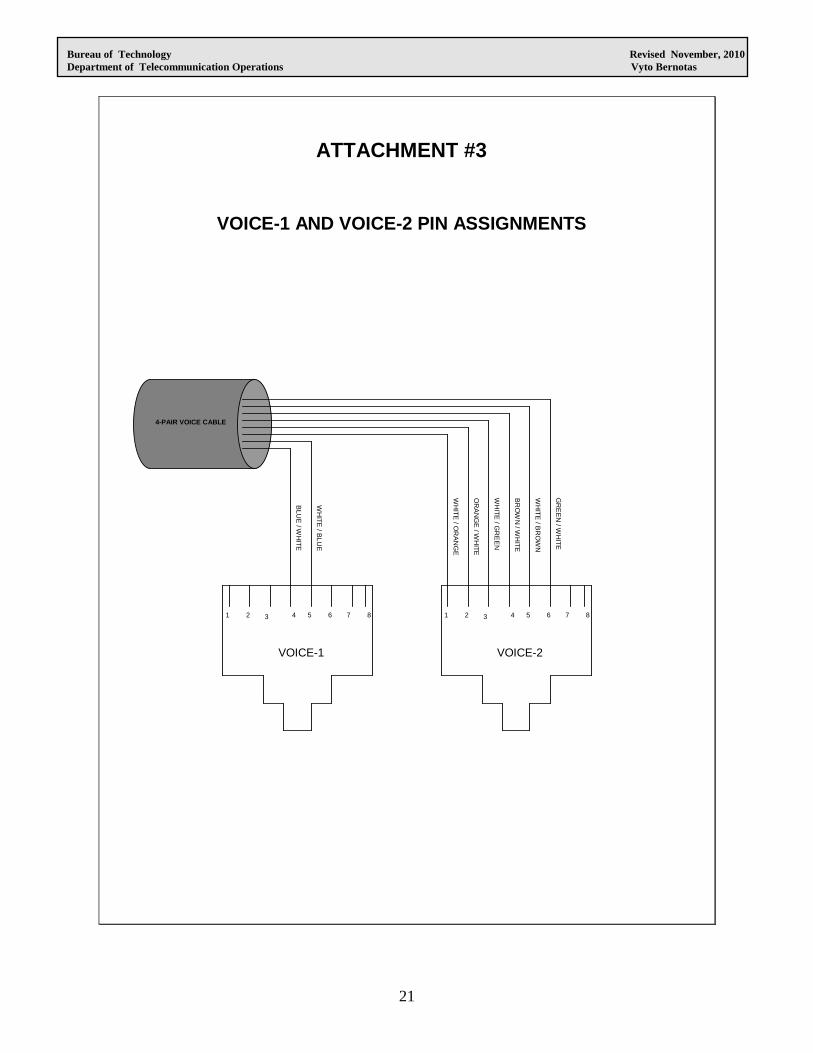
NOTES: 1. PORTS V1 AND V2 ARE WIRED FROM ONE SPLIT CAT-3 CABLE. REFER TO ATTACHMENT #3 FOR PIN CONFIGURATION.
VOICE-2 (V2) NOTE 1 NOTE 1 LIGHT GREY RJ 45 4 VOICE-1 (V1) GREY 4-PAIR CAT-3 IVORY RJ 45 3 DATA-2 (D2) WHITE 4-PAIR CAT-5E RED RJ 45 2 DATA-1 (D1) BLUE 4-PAIR CAT-5E ORANGE RJ 45 1 APPLICATION JACKET COLOR TYPE JACK COLOR TYPE PORT CABLE JACK
OUTLET CONFIGURATION
Bureau of Technology Revised November, 2010 Department of Telecommunication Operations Vyto Bernotas
21
ATTACHMENT #3
VOICE-1 AND VOICE-2 PIN ASSIGNMENTS
1 3 4 5 62 7 8 1 3 4 5 62 7 8
VOICE-1 VOICE-2
BLU
E / W
HITE
WH
ITE / B
LUE
WH
ITE / O
RA
NG
E
OR
AN
GE
/ WH
ITE
WH
ITE / G
RE
EN
BR
OW
N / W
HITE
WH
ITE / B
RO
WN
GR
EE
N / W
HITE
4-PAIR VOICE CABLE