control of a loaded induction machine using a feedforward neural network
TRANSCRIPT

This article was downloaded by: [UQ Library]On: 06 November 2014, At: 20:49Publisher: Taylor & FrancisInforma Ltd Registered in England and Wales Registered Number: 1072954 Registered office: Mortimer House,37-41 Mortimer Street, London W1T 3JH, UK
International Journal of Systems SciencePublication details, including instructions for authors and subscription information:http://www.tandfonline.com/loi/tsys20
Control of a loaded induction machine using afeedforward neural networkMOHAMED CHTOUROU a , NABIL DERBEL a & MOHAMED BEN ALI KAMOUN aa Department de Génie Electrique, Ecole Nationale d'Ingenieurs de Sfax , Laboratoired'Elcctrotechnique et d'Automatique (LETAU) , Route de Soukra Km 3.5, Sfax, 3038, TunisiaPublished online: 16 May 2007.
To cite this article: MOHAMED CHTOUROU , NABIL DERBEL & MOHAMED BEN ALI KAMOUN (1996) Control of a loadedinduction machine using a feedforward neural network, International Journal of Systems Science, 27:12, 1287-1295, DOI:10.1080/00207729608929335
To link to this article: http://dx.doi.org/10.1080/00207729608929335
PLEASE SCROLL DOWN FOR ARTICLE
Taylor & Francis makes every effort to ensure the accuracy of all the information (the “Content”) contained in thepublications on our platform. However, Taylor & Francis, our agents, and our licensors make no representationsor warranties whatsoever as to the accuracy, completeness, or suitability for any purpose of the Content. Anyopinions and views expressed in this publication are the opinions and views of the authors, and are not theviews of or endorsed by Taylor & Francis. The accuracy of the Content should not be relied upon and should beindependently verified with primary sources of information. Taylor and Francis shall not be liable for any losses,actions, claims, proceedings, demands, costs, expenses, damages, and other liabilities whatsoever or howsoevercaused arising directly or indirectly in connection with, in relation to or arising out of the use of the Content.
This article may be used for research, teaching, and private study purposes. Any substantial or systematicreproduction, redistribution, reselling, loan, sub-licensing, systematic supply, or distribution in anyform to anyone is expressly forbidden. Terms & Conditions of access and use can be found at http://www.tandfonline.com/page/terms-and-conditions

lnternational Journal of Systems Science, 1996, volume 27, number 12, pages 1287-1295
Control of a loaded induction machine using a feedforward neuralnetwork
MOHAMED CHTOUROUt, NABIL DERBELt and MOHAMED BEN Au KAMOUNt
Neural networks have been the subject of great interest in the control field. They seemto offer good ability to solve complex tasks. In this paper, some results ofusing a neuralnetwork for the nonlinear control of an induction machine's speed are presented. Theneural controller is a feedforward neural network identified off-line. The backpropaqationlearning alqorithm has been used for the off-line identification of the plant inverse neuralmodel which provides the comrol action. Simulations under measurement noise andenvironmemal condition variations have been investigated and comparison of performance has been made with an adaptive neural controller. The obtained results showthe efficiency and the implementation simplicity of the presented strategy.
I. Introduction
Induction machines are the machines of choice in manyindustrial applications due to their reliability, ruggednessand relatively low cost. They are often used to ensurethe variation in speed of industrial processes. Theinduction machine is (appropriately) named after the factthat the currents in the stator are electromagneticallyinduced by a rotating magnetic field set up by the stator.The control of induction machines is difficult since it isachieved through the only accessed terminals, which arethe stator winding ones. The induction machine presentsan extremely challenging control problem. This is dueprimarily to three issues; (I) the dynamic model of thesystem is nonlinear; (2) two of the state variables (rotorfluxes) are not usually measurable; and (3) due to ohmicheating, the rotor resistance varies considerably with acorresponding significant effect on the system dynamics(Chiasson 1993). The first issue just enumerated isconsidered in this work.
Conventional induction machine dynamic controlmethods, such as field oriented control, feedbacklinearization and direct self-control attempt to reduce thecomplex nonlinear dynamics structure into a linearstructure, in order to enable the application of linear
Received I December 1995.Revised 17April 1996.Accepted 24 April1996.
t Laboratoire d'Electrotechnique et d'Automatique (LETAU),Departcrnent de Genic Electrique, Ecole Nationale d'Ingenieurs deSfax, Route de Soukra Km 3.5, 3038 Sfax, Tunisia.
design techniques (Wishart and Harley 1995). The fieldoriented control has proved to be one of the mostsignificant methods to achieve high performance inadjustable speed induction motor drives. The basic taskof this scheme is the decoupling of the rotor flux terms,which permits torque attributes similar to those of directcurrent machines. Decoupling is accomplished by theapplication of a slip command signal dependent on theestimate of the rotor time constant (Theocharis andPetridis 1994). The realization of the field control schemerequires exact knowledge of the rotor flux terms.However, the rotor flux cannot be directly measured insquirrel cage induction motors. Furthermore, the majordisadvantage of the field control is its sensitivity to rotortime constant variations. Inaccurate estimates of thisparameter result in the deterioration of the performanceof the ind uction motor drive (Theocharis and Petridis1994, Taylor 1994).
In this work, the learning control of an inductionmachine is considered. It is shown that a well trainedfeedforward neural network is able to learn the inversedynamics of an induction machine and so accomplishes,as a consequence, the neural control of the machine speed.
Neural networks have been applied more and morefor various problems. They represent an attempt to modelthe human brain and have the potential for verycomplicated behaviour. As parallel information processing machines they are able to attack a large class ofproblems involving complexity, nonlinearity and uncertainties of a high order. Neural net models are specifiedby the net topology, node characteristics and training or
0020.7721/96 $12.00 © 1996 Taylor & Francis Ltd.
Dow
nloa
ded
by [
UQ
Lib
rary
] at
20:
49 0
6 N
ovem
ber
2014

1288 M. Chtourou et al.
2. Feedforward neural networks for dynamic systems
2.1. Definition
The feedforward neural networks adopted in thisinvestigation arc the most popular architecture used inthe control field. They consist of several layers ofprocessing units (the artificial neurons) where neuronconnections occur only between adjacent layers as shownin Fig. I. The former presents a three-layered networkwhere input layer neurons introduce each input to theneurons of the hidden layer. Hidden neurons make aweighted sum of all their inputs, and then apply a transfer(or activation or squashing) function to this sum. Sucha function can be linear or nonlinear (a threshold,sigmoid, sine or hyperbolic tangent function). The mostcommonly used function is the sigmoidal one. A constantinput equals I, which is considered to add a constant to
(2)
(I)
(4)
(3)
(7)
(6)
(5)
(8)
1f(x) = x
l+e
N+l
ej = L Xi Hliji=l
N+ I
ek = L SjWjk'j= 1
Yk = f(ek), k = I, ... , L.
the weighted sum. The output of a neuron is finallydistributed to the neurons of the next layer. The inputsand the outputs of units j and k are given respectivelyby the following equations
1 ~ d 2e = - L.. (Yk - Yk) ,2 k= I
where Y. and y~ are the neural network and the desiredoutputs, respectively (k = 1,2, ... , L, see Fig. I). Then,e is used to adapt each weight between layers III and n,with
f is the sigmoidal function which is defined by thefollowing expression
Furthermore, E is the learning rate and I is the counteriteration.
The second term of (7) represents the fraction of theerror gradient that is propagated through the network.It is given by:
(1) hidden layer-output layer
ae, d-- = f (ek)(Y. - Yk)SjaWjk
This function is useful between 0·05 and 0'95, so thatdata must be normalized.
A three-layered neural network (see Fig. I), is able toapproximate all continuous multivariable functions(Cybenko 1989). The quality of the model relies stronglyon how well the learning algorithm is able to extract theessence of the data in order to get a representation ofthe dynamic behaviour of the process. The fittingparameters of the neuron models are the connectionweights, which are obtained from a learning or trainingprocess. Backpropagation is a modified version of thegradient descent method used to minimize the sum ofthe squared output error. This commonly used learningalgorithm is briefly outlined (Rumelhart et al. 1986). Thetraining inputs are presented to the network, the outputsare computed and the error is obtained
Yl
Yk
YL
Figure I. Feedforward neural network.
1
Xi
learning rules. These rules specify an initial set of weightsand indicate how weights should be adapted during useto improve performances (Lippmann 1987).
Recent applications of neural networks on electricmachines include: the estimation of feedback signals fora vector controlled induction motor drive (Godoy andBimal 1995), the identification of the mechanical andcurrent-fed system dynamics of an induction machine forcontrol purposes (Wishart and Harley 1995), the designof a neural-network based adaptive observer forinduction motor control (Theocharis and Petridis \994),the modelling of the non-linear saturation characteristicsof a synchronous generator (Tsai et al. 1995) and theidentification of saturated synchronous machine parameters under diverse operating conditions of a turbogenerator (Chaudhry et al. 1995).
This paper focuses on the issue of the induetionmachine controlled speed by a plant inverse neural model;~ 2 deals with (he characteristics of neural networks andsome concepts used for neural control. In § 3, simulationresults concerning this investigation are presented anddiscussed.
Dow
nloa
ded
by [
UQ
Lib
rary
] at
20:
49 0
6 N
ovem
ber
2014
Control of a loaded induction machine 1289
Yt+d
Yt
Yt-l
ut-l
ut-2
1
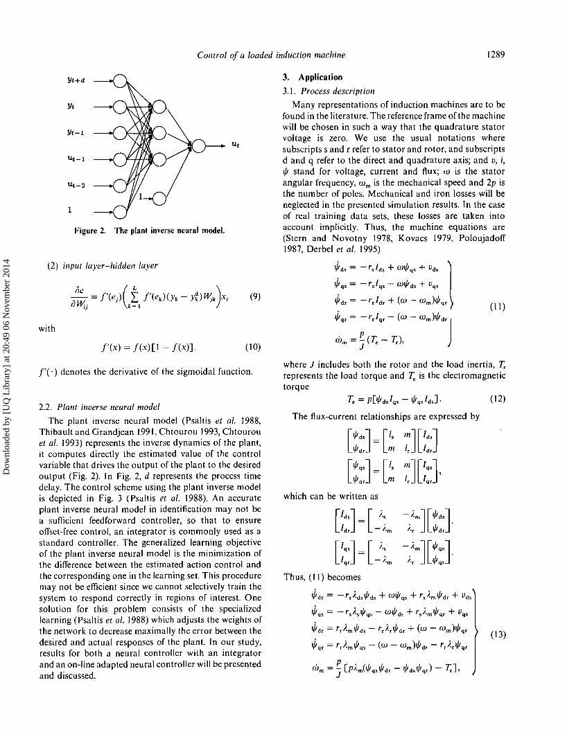
Figure 2. The plant inverse neural model.
3. Application
3.1. Process description
Many representations of induction machines are to befound in the literature. The reference frame of the machinewill be chosen in such a way that the quadrature statorvoltage is zero. We use the usual notations wheresubscripts sand r refer to stator and rotor, and subscriptsd and q refer to the direct and quadrature axis; and v, i,t/! stand for voltage, current and flux; w is the statorangular frequency, W m is the mechanical speed and 2p isthe number of poles. Mechanical and iron losses will beneglected in the presented simulation results. In the caseof real training data sets, these losses are taken intoaccount implicitly. Thus, the machine equations are(Stern and Novotny 1978, Kovacs 1979, Poloujadoff1987, Derbel et al. 1995)
(2) input layer-hidden layer
with
f'(x) = f(x)[1 -- f(x)].
(9)
(10)
~d' = -r,lds + wt/!q, + Vds
~qS = -r,lqs - Wt/!ds + Vqs
~d' = -r,Id' + (w - wm)t/!q,
~q, = -r,lq, - (W - Wm)t/!d,(II)
1'(') denotes the derivative of the sigmoidal function.where J includes both the rotor and the load inertia, T,represents the load torque and 1; is the electromagnetictorque
2.2. Plant inverse neural model
The plant inverse neural model (Psaltis et al. 1988,Thibault and Grandjean 1991, Chtourou 1993, Chtourouet al. 1993) represents the inverse dynamics of the plant,it computes directly the estimated value of the controlvariable that drives the output of the plant to the desiredoutput (Fig. 2). In Fig. 2, d represents the process timedelay. The control scheme using the plant inverse modelis depicted in Fig. 3 (Psaltis et al. 1988). An accurateplant inverse neural model in identification may not bea sufficient feedforward controller, so that to ensureoffset-free control, an integrator is commonly used as astandard controller. The generalized learning objectiveof the plant inverse neural model is the minimization ofthe difference between the estimated action control andthe corresponding one in the learning set. This proceduremay not be efficient since we cannot selectively train thesystem to respond correctly in regions of interest. Onesolution for this problem consists of the specializedlearning (Psaltis et al. 1988) which adjusts the weights ofthe network to decrease maximally the error between thedesired and actual responses of the plant. In our study,results for both a neural controller with an integratorand an on-line adapted neural controller will be presentedand discussed.
1; = P[t/!d,lqs - t/!q,lds].
The flux-current relationships are expressed by
which can be written as
Th us, (II) becomes
~dS = -rJdst/!ds + wt/!qS + rS)'mt/!d' + Vds
~qS = -r,Ast/!qs - Wt/!ds + r,).mt/!q, + Vqs
~d' = r,).mt/!ds - r,)·,t/!d' + (W - Wm)t/!q,
~q, = rJmt/!qs - (W - Wm)t/!d, - r,).,t/!q,
( 12)
(13)
Dow
nloa
ded
by [
UQ
Lib
rary
] at
20:
49 0
6 N
ovem
ber
2014

1290 M. Chtourou et al.
withk = 0'1070.
which can be expressed in the condensed form as:'. TX = ~(X, U), with X = [!/Jd' !/Jq, !/Jd' !/Jq, wm ] repre-scnting thc state vector of the machine and U =[Vd, Vq , w]T. The output is the mechanical speed W m . Theinput of thc machine is vd, (vq , = 0 and W is constant).
The machine parameters are:
of neurons in the hidden layer is problem-dependent andis empirically determined. The influence of the hiddenneuron number on the control performance will betreated in the next paragraph. Plant inverse neuralmodels were identified and tested for various networkarchitectures. The retained one was composed of six inputneurons, \3 hidden neurons and one output. The inputsof the neural controller were: y*(t), yet), u(t - I), u(t - 2),u(e - 3) and the constant input; where yet) and ute) denoterespectively the induction machine speed and the statorvoltage at the sampling period t. The first input (denotedby y*(t)) is either the output of the plant (at the samplingperiod t + \ in the learning phase) or the desired outputin the control operation. The training samples werecollected by varying the stator voltage between theminimum value 0, to the maximum value \·5 Vdsn, andby integrating the state model described above (equation(13)) from 0 to 8 s with a sampling rate equal to 10- 3 s.The neural controller has been identified off-line using thebackpropagation algorithm. Weights have been randomlyinitialized and the learning algorithm was specifiedinitially with: € = 0·4.
Once an accurate plant inverse neural model has beenidentified, it can be used as a feedforward controller. Thecontrol algorithm runs as follows: having the plant outputvalue yet) and the desired response, the control variableis evaluated by the feedforward controller (described byFig.3) and applied to the machine model (equations (13))to compute the next simulated output at (t + I). It is tobe noted that a noise was added to the plant output inorder to simulate experimental conditions. The desired
(14)
Vd,n = 220J3 V
J = 0·5 kg m 2
r, = 0·38 Q
1,=50x 10-3H.
w = lOOn rad S-I
3.2. Simulation results
This section presents the simulation results obtainedfor thc control of the induction machine described in § 2.Two phases should be considered: training and operatingphases. In the first, the training set and the netarchitect urc should be chosen to identify the plant inverseneural model. The second step uses the identified net asthe controller, The controller performance is stronglydependent on the neural net architecture. The number
p=4
r, = 0·29 Q
m = 47·3 x 10- 3 H
1,=50x 1O- 3H
This machine works in its nominal operation. The loadwas specified by a mechanical torque which is proportional to thc machine speed
y'(t)y(t)
(a)
y' (t)
: Delay :
IPlant Inverse Neural Model~
++,.." I
Integrator i +,<?\- -1 Process i'<.;>' I ,<y
-y[t)
(b)
Figure 3. The control scheme,
Dow
nloa
ded
by [
UQ
Lib
rary
] at
20:
49 0
6 N
ovem
ber
2014

Control of a loaded induction machine 1291
600,---,----.---
t(s)
4 53254321
(a) (b)
Figure 4. The stator voltage (V) (a) and the machine speed evolutions (rad S-I) (bj, for the six-hidden-neuron controller, without theintegrator. The broken line corresponds to the desired output.
output is presented in the figures by the broken curves.
3.2.1. The controllerarchitectureeffect. In this paragraph,we are interested in the study of the hidden neuron numbereffect on the quality of the control. As an illustration,two examples of control by two accurately identifiedplant inverse neural models (with six and 13 hiddenneurons) were presented. Figure 4 shows, respectively,the stator voltage and the machine speed evolutionswithout using the integrator. These results were obtainedfor the six-hidden-neuron controller. The set point forthe induction machine speed was changed as shown inFig. 4. The identified plant inverse neural model is notan efficient controller. In Fig. 5, the same evolutions
accomplished by the l3-hidden-neuron controller werepresented. Although this controller gave better results(Figs 5(c) and 5(d», it presented oscillations about thesetpoint as shown in Figs 5(a) and 5(h). It was a goodcontroller for y* = 75 rad S-1 (Figs 5(c) and 5(d»,but it was not for y* = 65 rad S-1 (Figs 5(a) and 5(h».Thus, the identified plant inverse neural model has notbeen a performing controller for some operating points.
3.2.2. The specialized learning effect. The followingresults present the effect of the use of a neural controlleradapted on-line with specialized learning. This type oflearning uses the difference between actual and desiredoutputs of the plant to modify the weights of the
321
300 1\0
200
100
00' t(s)
1 2 3 4 5 1 2 3 5
(a) (b)
400
(e) (d)
Figure 5. The stator voltage (V)«a) and (el)and the machine speed evolutions (rad s -I) «b) and (eI)), for the l3-hidden-neuron controller,without the integrator. The broken lines correspond to the desired output (Figs (a), (b) and (e), (eI) for two different desired trajectories).
Dow
nloa
ded
by [
UQ
Lib
rary
] at
20:
49 0
6 N
ovem
ber
2014
1292 M. Chtourou et al.
400,--..,.--------.----r--..,.--------,
1 2 3
(a) (d)
500 r---,-----,----,------.------, 80 r---,-----,----,------r-----,
t(s)
4 532
(e)
"."'..- --_. r -
1
(b)
-0.812,----r--~-_____,_-~r__ -0.808 ,----r----,----,----r_-----,
432
(f)
-0.81 . - ..·--,·----·,......·..,·;·------"'1'--
-0.812t'-"'ii- -:. --,---, -- , .. ,-~-0.814 .... -- ":";'-"'"0---0-'---
t(s)-0.816
0-..Li--.L---~---'--~5
5t(s)
43
(e)
21-0.818
0
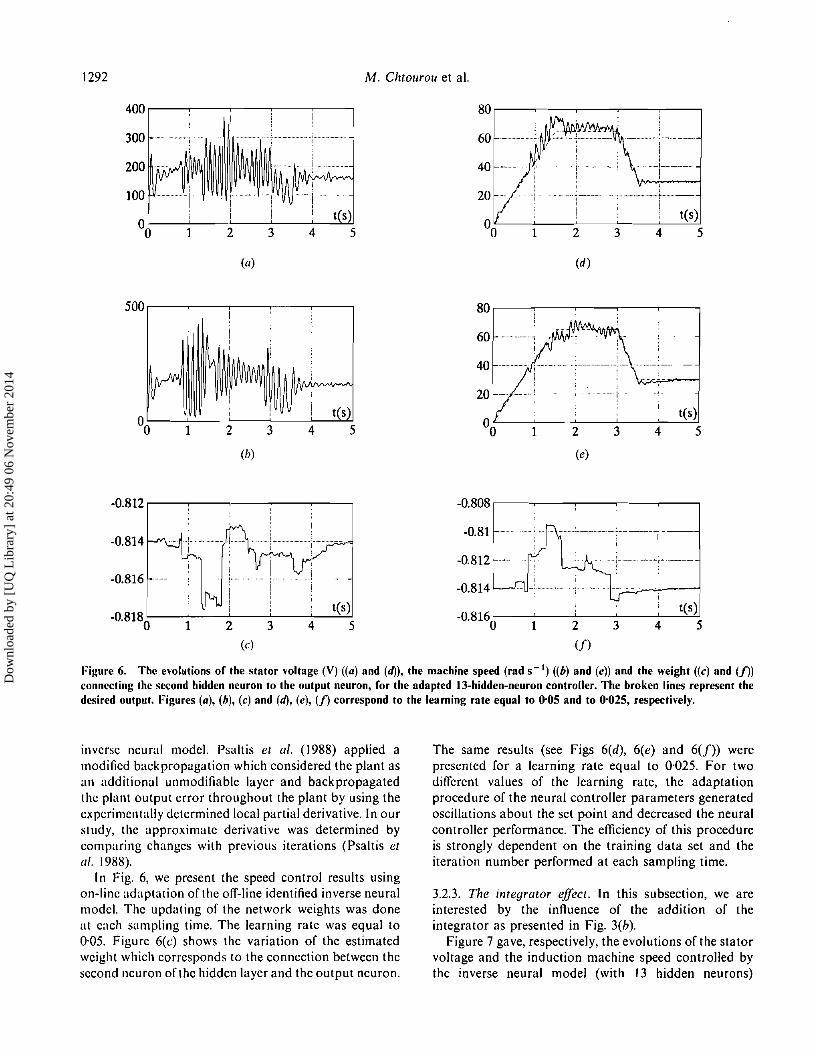
Figure 6. The evolutions of the stator voltage (V) «a) and (d)), the machine speed (rad S-I) «b) and (e)) and the weight ((e) and (f))
connecting the second hidden neuron to the output neuron, for the adapted l3-hidden-neuron controller. The broken lines represent thedesired output. Figures (a), (b), (e) and (d), (e), (f) correspond to the learning rate equal to 0'05 and to 0'025, respectively.
inverse neural model. Psaltis et al. (1988) applied amodified back propagation which considered the plant asan additional unmodifiable layer and back propagatedthe plant output error throughout the plant by using theexperimentally determined local partial derivative. In ourstudy, the approximate derivative was determined bycomparing changes with previous iterations (Psaltis etal. 1988).
In Fig. 6, we present the speed control results usingon-line adaptation of the off-line identified inverse neuralmodel. The updating of the network weights was doneat each sampling time. The learning rate was equal to0·05. Figure 6(c) shows the variation of the estimatedweight which corresponds to the connection between thesecond neuron ofthc hidden layer and the output neuron.
The same results (see Figs 6(d), 6(e) and 6(f)) werepresented for a learning rate equal to 0·025. For twodifferent values of the learning rate, the adaptationprocedure of the neural controller parameters generatedoscillations about the set point and decreased the neuralcontroller performance. The efficiency of this procedureis strongly dependent on the training data set and theiteration number performed at each sampling time.
3.2.3. The integrator effect. In this subsection, we areinterested by the influence of the addition of theintegrator as presented in Fig. 3(b).
Figure 7 gave, respectively, the evolutions of the statorvoltage and the ind uction machine speed controlled bythe inverse neural model (with 13 hidden neurons)
Dow
nloa
ded
by [
UQ
Lib
rary
] at
20:
49 0
6 N
ovem
ber
2014

Control of a loaded induction machine 1293
300 ,---~-~--T--'--------' 80 '---~-~--'-----r-----,
200
100
1 2
(a)
3t(s)
4 5
80 ,---~-~--~--,--------,
t(s)
1 2
(e)
3 4 5
Figure 7. The evolutions of the stator voltage (a), the machine speed (b) and the direct (e) and the quadrature (tf) stator currents forthe 13 hidden neuron controller using the integrator. The broken line represents the desired output.
in parallel with an integrator. Compared with the resultspresented in Figs 5(a) and 5(b), or those presented inFigs 6(a)-6(e) the oscillatory behaviour of the controland the controlled variables became more damped (Figs7(a) and 7(b)). The current evolutions can be observed inFigs 7(c) and 7(d). As observed in these figures, theintroduction of the integrator leads to better results.
3.2.4. The environmental condition effects. To test theperformance of the neural controller (the 13-hiddenneuron plant inverse model with the integrator), twoexternal perturbations have been introduced.
(I) The first perturbation consists of the variation of therotor resistance. All the results presented in previoussubsections were obtained for the rotor resistancevalue measured after a loaded test. In the followingresults, the rotor resistance value was initially set to0·19 n then, after 2'5 seconds, its value suddenlyvaries to 0·38 n, due to the ohmic heating effect.Results of this simulation were presented in Fig. 8,corresponding respectively to the stator voltage, themachine speed, the direct stator current and thequadrature stator current evolutions. Referring tothese figures, the neural controller achieved anefficient control and rejected this external perturbation, which introduced transient small machine speedvariations. However, significant changes in the
voltage and the direct current of the stator windingswere observed.
(2) The second perturbation consists of adding a noiseto the value of the weight connecting the fourthhidden neuron to the output of the plant inverseneural model (see Fig. 9(a». Figure 9 gives respectively,the evolutions of the stator voltage and the machinespeed. Observing these figures, it is clear that theneural controller keeps the same performances.
Thus, the considered controller is relatively insensitiveto environmental conditions, particularly to the variationsof the machine parameters and to any precision errorsdue to the network weights identification.
4. Conclusion
This paper is concerned with the implementation of aneural controller for induction machine drives, andseveral comparisons are presented.
It is shown that the off-line identified neural controllerwith an integrator presents an efficient control and iseasier to implement. The adaptation of the neuralcontroller does not lead to good performances. This isessentially due to the use of one measure as learning data,and performing one iteration.
Some perturbations have been introduced to test thesensitivity of the considered controller. In particular,
Dow
nloa
ded
by [
UQ
Lib
rary
] at
20:
49 0
6 N
ovem
ber
2014

1294
400 r--~-~----'---"--_____,
(a)
80r---~-~-~-~----'
M. Chtourou et al.
(b)
or--'--~---,,---~---,
-50
-100
-150
1 2 3
(c)
t(s)
4 5 1 2
(d)
3t(s)
4 5
Figure II. Effects of rotor resistance variation on the evolutions of the stator voltage (a), the machine speed (b) and the direct (e) andthe quadrature (II) stator currents for the 13-hidden-neuron controller using the integrator. The rotor resistance was initially equal to()'19 fl, and it was twice multiplied between 2'5 and 5 s, The broken line represents the desired output.
·1.05 r--~--,--'-~-~r-_____, 400 r--.,------,--~--,.--_____,
-1.1
-1.15
1 2
(a)
t(s)4 5
(c)
Figure 9. Effects of the variation (a) of one controller parameter (the weight connecting the fourth hidden neuron to the outputneuron-Fig. 9(a) on the evolutions of the stator voltage (b) and the machine speed (e) for the 13-hidden-neuron controller usingthe integrator. The broken line represents the desired output.
Dow
nloa
ded
by [
UQ
Lib
rary
] at
20:
49 0
6 N
ovem
ber
2014

Control of a loaded induction machine 1295
the variations of the machine parameters and the networkweights do have not significant effects on the performancesof the plant inverse neural controller.
RefereneesCHAUDHRY. S. R., AHMED-ZAID, S., and DEMERDASH, N. A., 1995, An
artificial neural network method for the identification of saturatedlurbogenerator parameters based on a coupled finite-element/stalespace computational algorithm. IEEE Transaction on EnergyConversion. 10, 625-633.
CHIASSON, J., 1993, Dynamic feedback linearisation of the inductionmotor. IEEE Trallsactioll 011 Automatic Colltrol, 38, 1588-1594.
CHTOUROU, M., 1993, La Modelisation et la Commande des Precedespar les Reseaux Neuromirnetiques. Doctoral thesis, INP-Toulouse,September.
CHTOUROU, M., NAJlM, K., Roux, G., and DAHHOU, B., 1993, Controlof bioreactor using a neural network. Bioprocess Engineering, 8,251-254.
CYIlENCO, G., 1989. Approximation by superpositions of a sigmoidalfunction. Mathematics and Control Siqnals Systems, 2, 303-314.
DERIlEL, N., KAMOUN, M. B. A., and POLOUJADOFF, M.• 1995, On theorder reduction of induction machines during start-up. IEEETransactions on Energy Conversion, 10,4.
GODOY, S. M., and BIMAL, K. B., 1995, Neural network basedestimation of feedback signals for a vector controlled inductionmotor drive. IEEE Transactions 0/1 Industry Applications, 31,620-629.
KOVACS, P., 1979, Transient Operation ofElectrical Machines (Budapest,Hungary: Akademia Kiado).
LIpPMANN, R. P., 1987, An introduction 10computing with neural nets.IEEE ASSP Magazine, April, 4-22.
NARENDRA, K. S., and PARTHASARATHY, K., 1990, Dynamical systemsusing neural networks. IEEE Transactions on Neural Networks, 1,4-26.
POLOUJADOFF, M., 1987, The theory of three phase inductionsquirrel cage motors. Electric Machines and Power Systems, 13,245-264.
PSALTlS, D., SIDERIS, A., and YAMAMURA, M., 1988,A multilayer neuralnetwork controller. IEEE Control System Magazine, 8, 17-21.
RUMELHART, D. E., HINTON, G. E., and WILLIAMS, R. J., 1986, Learninginternal representation by error propagation. Parallel DistributedProcessing Explorations in the Microstructures of Cognition, I,318-362.
STERN, R., and NOVOTNY, D. W., 1978, A simplified approach to thedetermination of induction machine dynamic response. IEEETrallsactions on Power Apparatus and Systems, 97, 1430-1439.
TAYLOR, D. G., 1994, Nonlinear control of electric machines: anoverview. IEEE Control Systems, 14,41-51.
THEOCHARIS, J., and PETRIDIS, V., 1994, Neural network observer forinduction motor control. IEEE Control Systems, 14, 26-37.
THIBAULT, J., GRANDJEAN, B. P. A., 1991, Neural networks in processcontrol-a survey. IFAC Symposium 011 Advanced Control ofChemical Processes, 14-J6 October, Toulouse, France.
TSAI, H., KEYHANI, A., DEMCKO, J. A., and SELIN, D. A., 1995,Development of a neural network based saturation model forsynchronous generator analysis. IEEE Transaction on EnergyConversion. 10, 617-624.
WERIlOS, P. J., 1989, Neural networks for control and systemidentification. Proceedings of the 28th IEEE Conference 011 Decisionand Control, December, Tempa, Florida, U.S.A.
WISHART, M. T., and HARLEY, R. G., 1995, Identification and controlof induction machines using artificial neural networks. IEEETransaction on Industry Applications. 31, 612-619.
Dow
nloa
ded
by [
UQ
Lib
rary
] at
20:
49 0
6 N
ovem
ber
2014