control hvac - grundfosnet.grundfos.com/appl/ccmsservices/public/literature/filedata/gr... ·...
TRANSCRIPT

GRUNDFOS DATA BOOKLET
Control HVACFor variable-primary-flow systems

Ta
ble
of c
on
ten
ts
2
Control HVAC
1. Product description 3Introduction . . . . . . . . . . . . . . . . . . . . . . . . . . . . . . . . . . . . . . . . . . . . . . . . . . . . . . . . . . . . . . . . . . . . . . . . . . . . . . . . . . 3Applications . . . . . . . . . . . . . . . . . . . . . . . . . . . . . . . . . . . . . . . . . . . . . . . . . . . . . . . . . . . . . . . . . . . . . . . . . . . . . . . . . . 3Benefits . . . . . . . . . . . . . . . . . . . . . . . . . . . . . . . . . . . . . . . . . . . . . . . . . . . . . . . . . . . . . . . . . . . . . . . . . . . . . . . . . . . . . 4Features. . . . . . . . . . . . . . . . . . . . . . . . . . . . . . . . . . . . . . . . . . . . . . . . . . . . . . . . . . . . . . . . . . . . . . . . . . . . . . . . . . . . . 4Energy-optimised control . . . . . . . . . . . . . . . . . . . . . . . . . . . . . . . . . . . . . . . . . . . . . . . . . . . . . . . . . . . . . . . . . . . . . . . . 5
2. Construction 6Main cabinet. . . . . . . . . . . . . . . . . . . . . . . . . . . . . . . . . . . . . . . . . . . . . . . . . . . . . . . . . . . . . . . . . . . . . . . . . . . . . . . . . . 6Subcabinets . . . . . . . . . . . . . . . . . . . . . . . . . . . . . . . . . . . . . . . . . . . . . . . . . . . . . . . . . . . . . . . . . . . . . . . . . . . . . . . . . . 6
3. System configuration 7Pumps . . . . . . . . . . . . . . . . . . . . . . . . . . . . . . . . . . . . . . . . . . . . . . . . . . . . . . . . . . . . . . . . . . . . . . . . . . . . . . . . . . . . . . 7Bypass valve . . . . . . . . . . . . . . . . . . . . . . . . . . . . . . . . . . . . . . . . . . . . . . . . . . . . . . . . . . . . . . . . . . . . . . . . . . . . . . . . . 7Sensors . . . . . . . . . . . . . . . . . . . . . . . . . . . . . . . . . . . . . . . . . . . . . . . . . . . . . . . . . . . . . . . . . . . . . . . . . . . . . . . . . . . . . 7
4. Installation 8Location . . . . . . . . . . . . . . . . . . . . . . . . . . . . . . . . . . . . . . . . . . . . . . . . . . . . . . . . . . . . . . . . . . . . . . . . . . . . . . . . . . . . . 8Mechanical installation. . . . . . . . . . . . . . . . . . . . . . . . . . . . . . . . . . . . . . . . . . . . . . . . . . . . . . . . . . . . . . . . . . . . . . . . . . 8Electrical installation . . . . . . . . . . . . . . . . . . . . . . . . . . . . . . . . . . . . . . . . . . . . . . . . . . . . . . . . . . . . . . . . . . . . . . . . . . . 8
5. Control functions 9Operating modes . . . . . . . . . . . . . . . . . . . . . . . . . . . . . . . . . . . . . . . . . . . . . . . . . . . . . . . . . . . . . . . . . . . . . . . . . . . . . . 9System monitoring . . . . . . . . . . . . . . . . . . . . . . . . . . . . . . . . . . . . . . . . . . . . . . . . . . . . . . . . . . . . . . . . . . . . . . . . . . . . . 9
6. Product range 10Type key . . . . . . . . . . . . . . . . . . . . . . . . . . . . . . . . . . . . . . . . . . . . . . . . . . . . . . . . . . . . . . . . . . . . . . . . . . . . . . . . . . . 10Options. . . . . . . . . . . . . . . . . . . . . . . . . . . . . . . . . . . . . . . . . . . . . . . . . . . . . . . . . . . . . . . . . . . . . . . . . . . . . . . . . . . . . 10
7. Technical data 11Inputs and outputs . . . . . . . . . . . . . . . . . . . . . . . . . . . . . . . . . . . . . . . . . . . . . . . . . . . . . . . . . . . . . . . . . . . . . . . . . . . . 11Dimensions . . . . . . . . . . . . . . . . . . . . . . . . . . . . . . . . . . . . . . . . . . . . . . . . . . . . . . . . . . . . . . . . . . . . . . . . . . . . . . . . . 11Materials . . . . . . . . . . . . . . . . . . . . . . . . . . . . . . . . . . . . . . . . . . . . . . . . . . . . . . . . . . . . . . . . . . . . . . . . . . . . . . . . . . . 11
8. Accessories 12DPI V.2 differential-pressure sensor . . . . . . . . . . . . . . . . . . . . . . . . . . . . . . . . . . . . . . . . . . . . . . . . . . . . . . . . . . . . . . 12M12 cable . . . . . . . . . . . . . . . . . . . . . . . . . . . . . . . . . . . . . . . . . . . . . . . . . . . . . . . . . . . . . . . . . . . . . . . . . . . . . . . . . . 12Capillary tube . . . . . . . . . . . . . . . . . . . . . . . . . . . . . . . . . . . . . . . . . . . . . . . . . . . . . . . . . . . . . . . . . . . . . . . . . . . . . . . . 12VFI vortex flow sensor . . . . . . . . . . . . . . . . . . . . . . . . . . . . . . . . . . . . . . . . . . . . . . . . . . . . . . . . . . . . . . . . . . . . . . . . . 13TTA temperature sensor . . . . . . . . . . . . . . . . . . . . . . . . . . . . . . . . . . . . . . . . . . . . . . . . . . . . . . . . . . . . . . . . . . . . . . . 13
Pro
du
ct
de
sc
rip
tio
n
Control HVAC 1
1. Product description
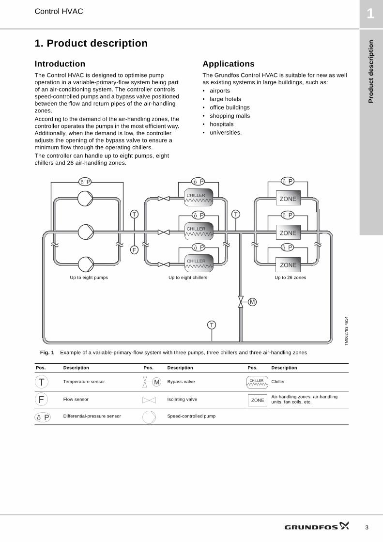
IntroductionThe Control HVAC is designed to optimise pump operation in a variable-primary-flow system being part of an air-conditioning system. The controller controls speed-controlled pumps and a bypass valve positioned between the flow and return pipes of the air-handling zones.
According to the demand of the air-handling zones, the controller operates the pumps in the most efficient way. Additionally, when the demand is low, the controller adjusts the opening of the bypass valve to ensure a minimum flow through the operating chillers.
The controller can handle up to eight pumps, eight chillers and 26 air-handling zones.
ApplicationsThe Grundfos Control HVAC is suitable for new as well as existing systems in large buildings, such as:
• airports
• large hotels
• office buildings
• shopping malls
• hospitals
• universities.
Fig. 1 Example of a variable-primary-flow system with three pumps, three chillers and three air-handling zonesT
M0
62
78
3 4
61
4
Pos. Description Pos. Description Pos. Description
Temperature sensor Bypass valve Chiller
Flow sensor Isolating valveAir-handling zones: air-handling units, fan coils, etc.
Differential-pressure sensor Speed-controlled pump
T
△P
M
△P
CHILLER
△P △P
CHILLERZONE
CHILLER
△P
CHILLER
CHILLER
△P
CHILLER
△P
T
F
ZONE
ZONE
T
Up to eight pumps Up to eight chillers Up to 26 zones
T M CHILLER
F ZONE
△P
3
Pro
du
ct d
es
crip
tion
4
Control HVAC1
Benefits
Energy-optimised control
• Supply-to-demand philosophy.
• Reduced energy consumption without compromising comfort.
• Pumps are connected in parallel and operate in the most efficient way.
• Can handle up to eight pumps, eight chillers and 26 air-handling zones, e.g. the most critical zones.
• Bypass valve ensures minimum flow through chillers.
High quality
• High system stability
• durability.
Simplicity
• Intuitive user interface
• easy commissioning
• easy system configuration
• easy integration into any building management system (BMS)
• standard-packaged system.
Features
Control
• Designed for variable-primary-flow systems
• speed and cascade control of pumps
• two operating modes for the system:
– Auto/Remote
– Manual/Local.
• three operating modes for pumps:
– Auto
– Manual
– Off.
• two operating modes for the bypass valve:
– Auto
– Manual.
Hardware
• Main cabinet with user interface
• subcabinets for additional air-handling zones
• inputs for flow, differential-pressure and temperature sensors
• alarm outputs.
User interface
• 7" colour touchscreen
• selector switches for system and pumps.
Remote management (optional)
• Possible integration into building management and SCADA systems via standard protocols BACnet IP and Modbus TCP
• possible integration with Grundfos Remote Management (GRM).

Pro
du
ct
de
sc
rip
tio
n
Control HVAC 1
Energy-optimised controlGrundfos Control HVAC is designed to optimise pump operation, regardless of the demand of the air-handling zones.
Chillers can only operate correctly within a specific flow range. Using the bypass valve, the controller ensures that this requirement is met at all times.
System requirements
In order for the Control HVAC to operate correctly, the following requirements must be met:
• Pumps, chillers and air-handling zones must be connected in parallel.
• The pump system must have a differential-pressure sensor.
• Each chiller must have a differential-pressure sensor.
• At least one differential-pressure sensor must be placed between the inlet and outlet of all the zones. Up to 26 differential-pressure sensors can be placed in critical zones in the system.
• Isolating valves with an electric contact must be placed at the outlet of every chiller.
• A bypass valve must be placed between the flow and the return pipes of the zones.
System control
The air-handling zones, chillers and isolating valves must be controlled by an external building management system. The Control HVAC controls the pumps and the bypass valve based on the feedback from the sensors and chiller isolating valves.
The cooling load of the air-handling zones determines the number of chillers in operation. According to the number of chillers in operation, the controller adjust the pump operation to maintain a differential pressure or flow rate across the chillers within the permissible range.
The controller then adjusts the pump operation further in order to meet the demand of the air-handling zone with the highest differential pressure, or in other words, with the highest flow rate.
If the flow rate is lower than the minimum flow rate required through the chillers, the controller opens the bypass valve and thus maintains a minimum flow rate across the chillers.
Pump cascade control
The Control HVAC is designed to control Grundfos E-pumps and CUE frequency converters, as well as other types of pumps with variable frequency drives (VFD).
• The performance is adjusted to the demand through cutting pumps in or out and through parallel control of the pumps in operation.
• The Control HVAC maintains a constant differential pressure through continuous adjustment of the speed of the pumps.
• Pump changeover is automatic and depends on load, operating hours and fault.
• All pumps in operation run at the same speed.
• The number of pumps in operation also depends on the energy consumption of the pumps. If only one pump is required, two pumps will run at a lower speed if this results in a lower energy consumption.
Examples of operation with one and with three E-pumps:
Fig. 2 One E-pump in operation
Fig. 3 Three E-pumps in operation
Bypass valve control
The Control HVAC takes the characteristics of the bypass valves into account when controlling the valve position. This ensure smooth and accurate adjustment of the valve at all times.
TM
00
79
95
22
96
TM
00
79
96
22
96
Q
H
Hset
Q
H
Hset
5
Co
ns
truc
tion
6
Control HVAC2
2. Construction
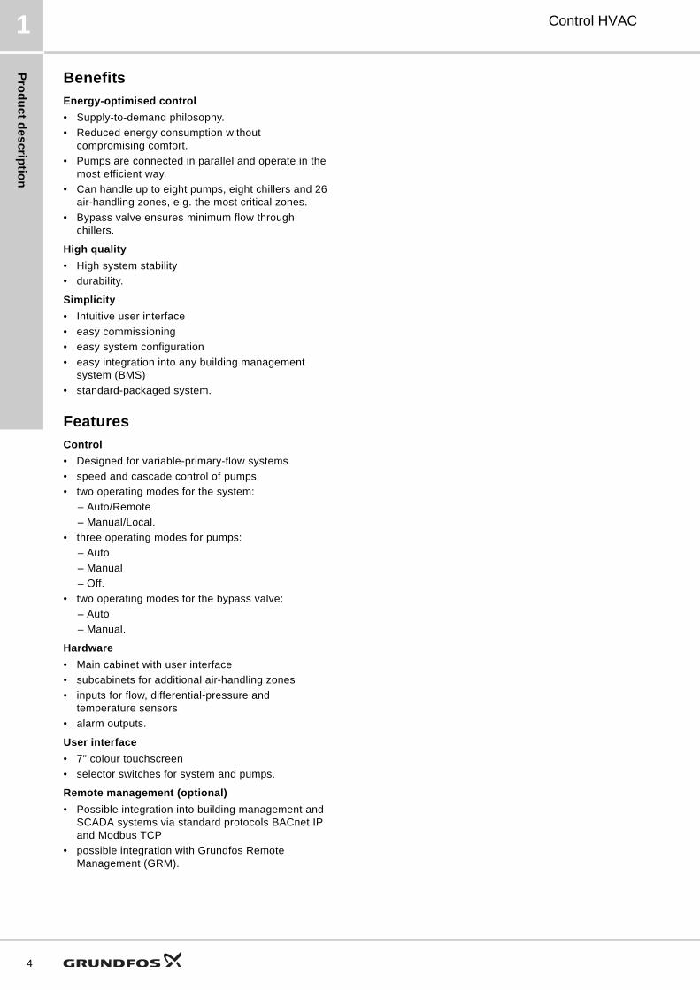
Main cabinetThe main cabinet hosts the controller, the user interface and the input and output terminals for the pumps, bypass valve, sensors, etc.
Fig. 4 Front panel of the main cabinet
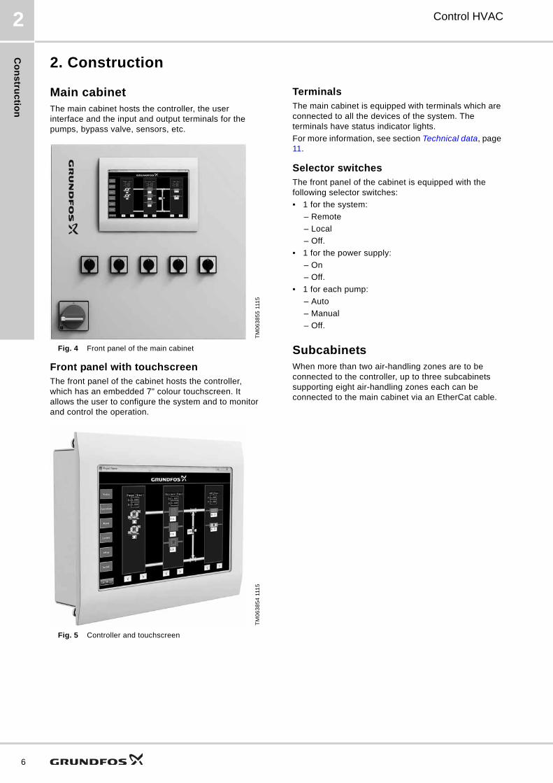
Front panel with touchscreenThe front panel of the cabinet hosts the controller, which has an embedded 7" colour touchscreen. It allows the user to configure the system and to monitor and control the operation.
Fig. 5 Controller and touchscreen
TerminalsThe main cabinet is equipped with terminals which are connected to all the devices of the system. The terminals have status indicator lights.
For more information, see section Technical data, page 11.
Selector switchesThe front panel of the cabinet is equipped with the following selector switches:
• 1 for the system:
– Remote
– Local
– Off.
• 1 for the power supply:
– On
– Off.
• 1 for each pump:
– Auto
– Manual
– Off.
SubcabinetsWhen more than two air-handling zones are to be connected to the controller, up to three subcabinets supporting eight air-handling zones each can be connected to the main cabinet via an EtherCat cable.
TM
06
38
55
111
5T
M0
63
85
4 1
115
Sy
ste
m c
on
fig
ura
tio
n
Control HVAC 3
3. System configuration
PumpsThe Control HVAC is designed for Grundfos E-pumps, Grundfos pumps with a CUE frequency converter and other pumps with a 0-10 V variable frequency drive.
The following Grundfos pumps are compatible with the Control HVAC:
• end-suction pumps: NK, NKE, NB, NBE
• vertical in-line volute pumps: TP, TPE
• horizontal split case pump: HS, KP, LS.
Bypass valveAs standard, the Control HVAC requires a bypass valve with a control signal of 4-20 mA. On request, the Control HVAC can be adapted for a bypass valve with a control signal of 0-10 V.
The Control HVAC has an input for feedback of the bypass valve position.
Sensors
Pump sensor
The pump system requires a differential-pressure sensor with a signal of 4-20 mA.
We recommend the Grundfos differential-pressure sensor, type DPI V.2.
Chiller sensors
The chillers require a differential-pressure sensor with a signal of 4-20 mA.
We recommend differential-pressure sensors with a short response time such as the Grundfos differential-pressure sensor, type DPI V.2.
Sensors for air-handling zones
The zones require differential-pressure sensors with a signal of 4-20 mA.
We recommend the Grundfos differential-pressure sensor, type DPI V.2.
Flow sensor
An additional flow sensor with a signal of 4-20 mA can be placed in the system and monitored via the controller screen.
The calculation of the specific energy requires a flow sensor.
We recommend the Grundfos vortex flow sensor, type VFI.
Temperature sensors
Two temperature sensors with a signal of 4-20 mA can be placed in the system and monitored via the controller screen.
We recommend the Grundfos TTA sensor.
For more information about Grundfos sensors, see section Product range, page 10 or product-selection.grundfos.com.
7

Ins
talla
tion
8
Control HVAC4
4. Installation
Location
Main cabinetThe main cabinet must be installed in a well-ventilated room to ensure sufficient cooling of its components.
Note: The main cabinet is not designed for outdoor installation and must not be exposed to direct sunlight.
SubcabinetsThe subcabinets must be installed in a well-ventilated room to ensure sufficient cooling of the system.
They must be installed at maximum 100 metres (328 feet) from the main cabinet.
Note: The subcabinets are not designed for outdoor installation and must not be exposed to direct sunlight.
Mechanical installationThe main cabinet and subcabinets can be mounted on a wall.
Electrical installationThe electrical installation must be carried out by authorised staff in accordance with local regulations and the wiring diagram supplied with the product. The electrical installation must be according to enclosure class IP54 (UL type 1).
The voltage and frequency of the power supply for the Control HVAC must correspond to the model delivered.
The devices of the system connect fast and easily to the terminals in the cabinets.

Co
ntr
ol
fun
cti
on
s
Control HVAC 5
5. Control functions
Operating modesIn automatic mode, the system operates according to the signals from the sensors, chillers, pumps and the bypass valve.
For maintenance or fault-finding purposes, it is, however, possible to control the system, pumps and valve manually from the controller, or to disconnect them individually from the controller.
Pumps
The operating mode of each pump can be set to "Manual", "Auto" or "Off" by means of selector switches on the main cabinet.
System
The operating mode of the system can be set to "Remote", "Local" or "Off" by means of a selector switch on the main cabinet.
Bypass valve
The control of the bypass valve can be set to "Auto", "Manual" or "Off" on the touchscreen.
Fault indications
The Control HVAC can show the following fault indications:
• sensor fault
• valve fault
• pump fault
• controller fault
• communication fault (between main cabinet and subcabinets).
System monitoringTo facilitate monitoring and testing of the system, the touchscreen shows information about each device connected to the controller.
Pumps
• Status: on, off or fault
• speed as percentage of maximum speed
• reference pressure of the pump system
• specific energy.
Chillers
• Status: on or off
• minimum differential pressure required across the chiller in focus, i.e. the one with the greatest deviation between the minimum differential pressure required and the actual differential pressure.
• differential pressure measured across the chiller in focus.
Air-handling zones
• Differential pressure of each zone
• reference differential pressure of the zone in focus, i.e. the one with the highest differential pressure
• differential pressure measured across the zone in focus.
Bypass valve
• Position as percentage of maximum opening angle.
Temperature
• Temperature at the pump system outlet
• temperature at the chiller outlet
• temperature at the zone outlet.
Flow rate
• Flow rate at the pump system outlet.
Note: Monitoring of temperature and flow rate requires sensors in the system.
Mode Description
AutoThe pump is controlled by the internal pump controller and runs as part of the pump cascade system.
Manual
The pump runs according to the settings made on the touchscreen. It can either start at a selected speed or stop. The pump is not controlled by the internal pump controller and therefore runs independently of the pump cascade system.
OffThe pump is switched off.The pump cannot be started via the touchscreen nor by a building management system.
Mode Description
Auto/Remote
The system operates according to the data collected by the controller. It can be controlled and monitored via the Grundfos Remote Management or a building management system.
Manual/Local
The communication to the Grundfos Remote Management or a building management system is deactivated. The controller operates according to the setting made on the touchscreen. The user can set a manual setpoint for the pump system and can stop the pump system.
Off
The controller is switched off. It cannot be activated via the touchscreen nor by a building management system.Note: The touchscreen is still on, and settings can be changed.
Mode Description
Auto The valve is controlled by the controller.
ManualThe valve is not controlled by the controller, and its position can be changed manually via the touchscreen.
Off The valve cannot be controlled by the controller.
9

Pro
du
ct ra
ng
e
10
Control HVAC6
6. Product range
Type key
Options
0-10 V control and feedback of bypass valve position All standard models are equipped with a 4-20 mA terminal for the control and feedback of the bypass valve position.
Optionally, it can be ordered with a 0-10 V terminal. See section Subcabinets, page 6.
Data communicationThe Control HVAC can be monitored and controlled by Grundfos Remote Management using GENIbus communication. It can also support other types of building management systems using BACnet IP and Modbus TCP.
This option must be ordered with the Control HVAC as it is configured during production.
Grundfos Remote Management requires a separate contract with Grundfos which hosts the Grundfos Remote Management database and servers.
Selector switches for pumpsAll standard models are equipped with selector switches for pumps on the front panel. See section Selector switches, page 6.
On request, it can be ordered without pump selector switches. In this case, the default pump operating mode is "Auto".
Subcabinet
DesignationProduct number
Description
Kit, HVAC, VPF 4, GENI 98899279
Controller for 1-4 Grundfos E-pumps or pumps with a Grundfos CUE frequency converter
Kit, HVAC, VPF 4, VFD 98899391Controller for 1-4 pumps with a variable frequency drive
Kit, HVAC, VPF 8, GENI 98899395
Controller for 5-8 Grundfos E-pumps or pumps with a Grundfos CUE frequency converter
Kit, HVAC, VPF 8, VFD 98899396Controller for 5-8 pumps with a variable frequency drive
Example: Control HVAC 3x 0-13 3x380 Type 3R OPT
Type range
Number of pumps (2x - 8x)
Current range of pumps in Ampere [A]
Supply voltage
Panel type: 3R (UL) or IP54 (IEC)
OPT: Optional equipment. See the nameplate for details.
Product name Product number
Kit set extension, IO 98913800
Te
ch
nic
al
da
ta
Control HVAC 7
7. Technical data
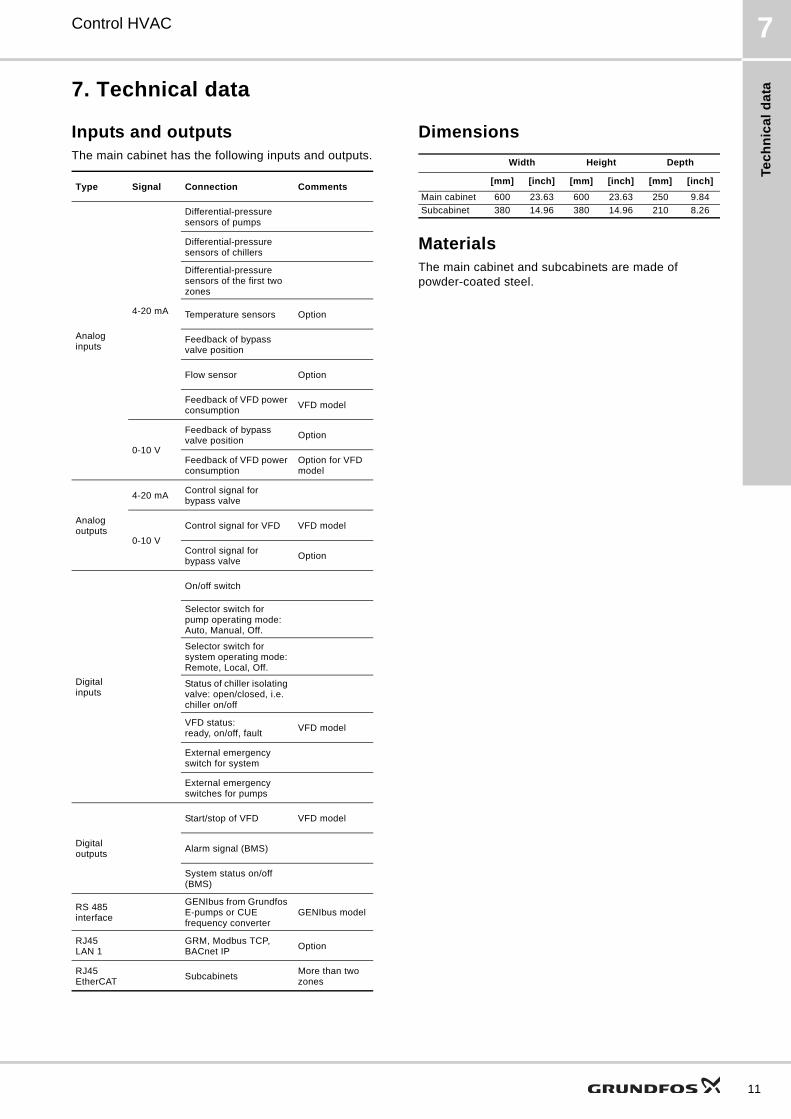
Inputs and outputs The main cabinet has the following inputs and outputs.
Dimensions
MaterialsThe main cabinet and subcabinets are made of powder-coated steel.
Type Signal Connection Comments
Analog inputs
4-20 mA
Differential-pressure sensors of pumps
Differential-pressure sensors of chillers
Differential-pressure sensors of the first two zones
Temperature sensors Option
Feedback of bypass valve position
Flow sensor Option
Feedback of VFD power consumption
VFD model
0-10 V
Feedback of bypass valve position
Option
Feedback of VFD power consumption
Option for VFD model
Analog outputs
4-20 mAControl signal for bypass valve
0-10 V
Control signal for VFD VFD model
Control signal for bypass valve
Option
Digital inputs
On/off switch
Selector switch for pump operating mode:Auto, Manual, Off.
Selector switch for system operating mode: Remote, Local, Off.
Status of chiller isolating valve: open/closed, i.e. chiller on/off
VFD status: ready, on/off, fault
VFD model
External emergency switch for system
External emergency switches for pumps
Digital outputs
Start/stop of VFD VFD model
Alarm signal (BMS)
System status on/off (BMS)
RS 485 interface
GENIbus from Grundfos E-pumps or CUE frequency converter
GENIbus model
RJ45LAN 1
GRM, Modbus TCP, BACnet IP
Option
RJ45 EtherCAT
SubcabinetsMore than two zones
Width Height Depth
[mm] [inch] [mm] [inch] [mm] [inch]
Main cabinet 600 23.63 600 23.63 250 9.84
Subcabinet 380 14.96 380 14.96 210 8.26
11
Ac
ce
ss
orie
s
12
Control HVAC8
8. Accessories
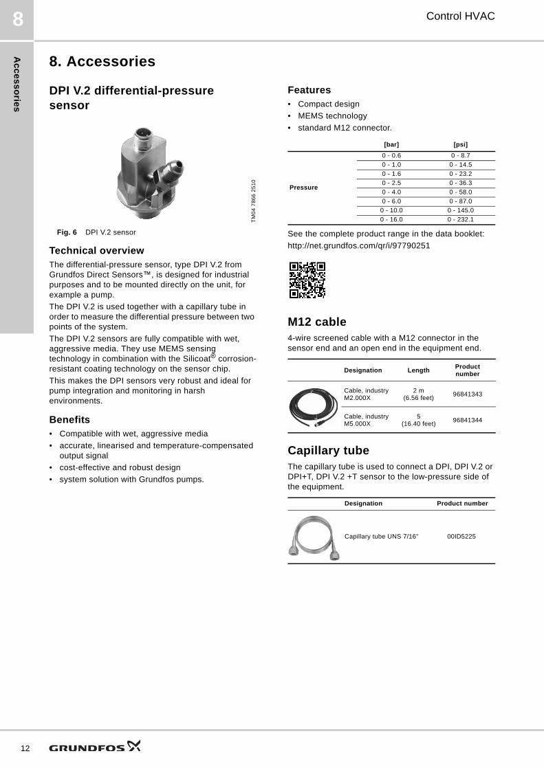
DPI V.2 differential-pressure sensor
Fig. 6 DPI V.2 sensor
Technical overview The differential-pressure sensor, type DPI V.2 from Grundfos Direct Sensors™, is designed for industrial purposes and to be mounted directly on the unit, for example a pump.
The DPI V.2 is used together with a capillary tube in order to measure the differential pressure between two points of the system.
The DPI V.2 sensors are fully compatible with wet, aggressive media. They use MEMS sensing technology in combination with the Silicoat® corrosion-resistant coating technology on the sensor chip.
This makes the DPI sensors very robust and ideal for pump integration and monitoring in harsh environments.
Benefits • Compatible with wet, aggressive media
• accurate, linearised and temperature-compensated output signal
• cost-effective and robust design
• system solution with Grundfos pumps.
Features• Compact design
• MEMS technology
• standard M12 connector.
See the complete product range in the data booklet:
http://net.grundfos.com/qr/i/97790251
M12 cable4-wire screened cable with a M12 connector in the sensor end and an open end in the equipment end.
Capillary tubeThe capillary tube is used to connect a DPI, DPI V.2 or DPI+T, DPI V.2 +T sensor to the low-pressure side of the equipment.
TM
04
78
66
25
10
[bar] [psi]
Pressure
0 - 0.6 0 - 8.7
0 - 1.0 0 - 14.5
0 - 1.6 0 - 23.2
0 - 2.5 0 - 36.3
0 - 4.0 0 - 58.0
0 - 6.0 0 - 87.0
0 - 10.0 0 - 145.0
0 - 16.0 0 - 232.1
Designation LengthProduct number
Cable, industryM2.000X
2 m(6.56 feet)
96841343
Cable, industry M5.000X
5(16.40 feet)
96841344
Designation Product number
Capillary tube UNS 7/16" 00ID5225

Ac
ce
ss
ori
es
Control HVAC 8
VFI vortex flow sensor
Fig. 7 VFI sensor
Technical overviewThe VFI sensor from Grundfos Direct Sensors™ is a flow sensor designed for industrial purposes. It is based on the principle of vortex shedding behind a bluff body. The VFI sensors are fully compatible with wet, aggressive media. They use MEMS sensing technology in combination with the Silicoat® corrosion-resistant coating technology on the sensor chip.
This makes the VFI sensors very robust and ideal for pump integration and monitoring in harsh environments.
The sensor is supplied with a stainless-steel flow pipe and has flanged or threaded ends for use with union nuts.
Benefits• No moving parts
• compatible with wet, aggressive media
• accurate, linearised and temperature-compensated output signal
• quick temperature response (direct contact with medium)
• cost-effective and robust design
• system solution with Grundfos pumps.
Features• Wide operating temperature range:
-30 - +120 °C (-22 - +248 °F)
• compact design
• MEMS technology.
See the complete product range in the data booklet:
http://net.grundfos.com/qr/i/97790189
For flow rates greater than 240 m3/h (1057 gpm), contact your local Grundfos sales company.
TTA temperature sensorThe sensor is a Pt100 temperature sensor fitted into a measuring tube.
The sensor is built into the system either by means of a cutting ring bush or by means of a protecting tube.
Features• 4-20 mA output
• measuring tube made of stainless steel DIN 1.4571
• sensor built into a type B connection head (DIN 43729) made of painted pressure-diecast aluminium with a Pg 16 screwed connection
• optional protective tube with G 1/2 connection.
Contact your local Grundfos company for product range.
TM
04
73
62
22
10
[m3/h] [gpm]
Flow rate
0.3 - 6 1.32 - 26.42
0.6 - 12 2.64 - 52.83
1.3 - 25 5.72 - 110.07
2.0 - 40 8.81 - 176.11
3.2 - 64 14.09 - 281.78
5.2 - 104 22.89 - 457.89
8-160 35.22 - 704.46
12-240 52.83 - 1056.69
13

GRUNDFOS A/S DK-8850 Bjerringbro . DenmarkTelephone: +45 87 50 14 00www.grundfos.com
98800761 0915
ECM: 1167474 Th
e n
am
e G
run
dfo
s, t
he
Gru
nd
fos
log
o,
an
d b
e t
hin
k i
nn
ov
ate
are
re
gis
tere
d t
rad
em
ark
s o
wn
ed
by
Gru
nd
fos
Ho
ldin
g A
/S o
r G
run
dfo
s A
/S,
De
nm
ark
. A
ll ri
gh
ts r
ese
rve
d w
orl
dw
ide
.©
Co
pyr
igh
t G
run
dfo
s H
old
ing
A/S