contol theory handbook
DESCRIPTION
Control Theory Handbook (nasa author: Doyle Garner)TRANSCRIPT
NASA TECHNICAL MEMORANDUM
i IACCfSSION NUMBER) ITHRUI
E e k (PAGE91 i
2 tNASA CR OR TUX OR AD NUMBER)
igl (CATEGO RYI
CONTROL THEORY HAND BOOK
by DOYLE G A R N E R .4ero-Astrodynamics L,aboratory
Microfiche (MF) /db NASA
George C. Murshdll Spuce Flzght Center,
Huntsville, Alubuma
4 1
GEORGE C. MARSHALL SPACE F L I G H T CENTER
TECHNICAL MEMORANDUM X-53036
CONTROL THEORY HANDBOOK
BY
Doyle Garner
CONTROL S T U D I E S BRAN CT DYNAMICS AND F L I G H T MECHANICS D I V I S I O N
AERO-ASTRODYNAMICS LABORATORY RESEARCH AND DEVELOPMENT OPERATIONS
TABLE OF CONTENTS
Page
I . INTRODUCTION . . . . . . . . . . . . . . . . . . . . . . . . . . . . . . . . . . . . . . . . . . . . . . . . . . . . . . . . . . . . . . . . . . . . . I1 DISCUSSION OF BASIC CONTROL PROBLEMS
. . . . . . . . . . . . . . . . . . . . . . . . A D r i f t f rom R e f e r e n c e T r a j e c t o r y B . S t r u c t u r a l Loads . . . . . . . . . . . . . . . . . . . . . . . . . . . . . . . . . . . . . .
. . . . . . . . . . . . . . . . . . . . . . . . . . . . C S t r u c t u r a l Bending Feedback ............................................ . D Fue l S l o s h
. . . . . . . . . . . . . . . . . . . . . E . Adequa t e Response t o D i s t u r b a n c e s
. . . . . . . . . . . . . . . . . . . . . . . . . . . . . . . . 111 . FLIGHT SYSTEM COORDINATES
...................................... . I V RIGID BODY EQUATIONS . . . . . . . . . . . . . . . . . . . . . . . . . . . . . . . . A D e r i v a t i o n of E q u a t i o n s . . . . . . . . . . . . . . . . . . . . . . . . . . . . . . . . B D r i f t Minimum C o n d i t i o n
.................................. C . Load Minimum C o n t r o l ........................................ . D Ga in S e l e c t i o n
................................... v . FLEXIBLE BODY EQUATIONS . . . . . . . . . . . . . . . . . . . . . . . . . . A Bending Modes and F r e q u e n c i e s 1 . Homogeneous Body . . . . . . . . . . . . . . . . . . . . . . . . . . . . . . . . . .
. . . . . . . . . . . . . . . . . . . . . . . . . . . . . . . 2 . Nonhomogeneous Body
........................ . B D e r i v a t i o n of Bending E q u a t i o n
V I . SLOSH EQUATION ............................................ .. . . . . . . . . . . . . . . . . . . . . . . . . . . . . . . . . . . . . . V I I . W I N D REPRESENTATION
. . . . . . . . . . . . . . . . . . . . . . V I I I TRANSFER FUNCTIONS AND BLOCK DIAGRAMS
. ............................. I X METHODS OF STABILITY ANALYSIS . ........................... A ~ o u t h ' s S t a b i l i t y C r i t e r i o n
. . . . . . . . . . . . . . . . . . . . . . . . . . B ~ u r w i t z ' s S t a b i l i t y C r i t e r i o n . ............................................ C Root Locus ............................. . D Frequency-Response Method . . . . . . . . . . . . . . . . . . . . . . . . E The N y q u i s t S t a b i l i t y C r i t e r i o n
. . . . . . . . . . . . . . . . . . . . . . . . . . . . . . . . . . . . . . . . . . x . ADAPTIVE CONTROL ......................................... . A Model Concept . . . . . . . . . . . . . . . . . . . . . . . . . . . . . . . . . . B A d a p t i v e Ga in C o n t r o l
.......................................... . C Gyro B l e n d e r
TABLE OF CONTENTS (Con t inued )
Page
APPENDICES
. A A c c e l e r o m e t e r E q u a t i o n ............................... 151
. . B R a t e Gyro ......................................... 155
................................. . C R a t e I n t e g r a t i n g Gyro 157
.......................... . D Aerodynamic Vane Type S e n s o r 1 6 1
................... . . E A c t u a t o r Engine T r a n s f e r F u n c t i o n 165
F . Summary o f V e h i c l e Dynamics I n c l u d i n g Bending and ................................................. S l o s h 169
. ....................................... G Bending Moment 179

Symbol
v 0
DEFINITION OF SYMBOLS AND UNITS
D e f i n i t i o n
a t t i t u d e a n g l e
a n g l e between r e f e r e n c e and i n e r t i a l v e l o c i t y v e c t o r
a n g l e of a t t a c k
c o n t r o l d e f l e c t i o n a n g l e
v e l o c i t y of v e h i c l e r e l a t i v e t o a i r
v e l o c i t y o f v e h i c l e
wind v e l o c i t y
d i r e c t i o n normal t o r e f e r e n c e
d i r e c t i o n normal t o v e h i c l e c e n t e r l i n e
v e h i c l e l o n g i t u d i n a l a x i s
t o t a l t h r u s t of t h e v e h i c l e b o o s t e r
t o t a l mass of t h e v e h i c l e
v e h i c l e moment of i n e r t i a abou t t h e CG
eng ine moment of i n e r t i a a b o u t h inge p o i n t
d r a g f o r c e
eng ine f i r s t moment of i n e r t i a a b o u t h inge p o i n t
dynamic p r e s s u r e
t h r u s t normal s l o p e of c o n t r o l e n g i n e s
aerodynamic normal f o r c e s l o p e
aerodynamic moment c o e f f i c i e n t
aerodynamic bending moment c o e f f i c i e n t
c o n t r o l f o r c e c o e f f i c i e n t
U n i t s
r a d
r a d
r a d
r a d
m / s
m/sec
m
m
kg
kg-sec2/m
kg-m-sec 2
kg-m-sec 2
kp-m/rad
kp -m/ rad

DEFINITION OF SYMBOLS AND UNITS (Cont 'd )
Symbol
c2
a 0
a 1
"0
g 2
&a = Xcg - Xa
D e f i n i t i o n U n i t s
c o n t r o l moment c o e f f i c i e n t l / s e c 2
d i sp lacement g a i n - -
r a t e g a i n s e c
a n g l e of a t t a c k g a i n - -
a c c e l e r o m e t e r g a i n sec2/m
d i s t a n c e from v e h i c l e CG t o a c c e l - m erome t e r
d i s t a n c e from v e h i c l e CG t o the CP m
d i s t a n c e from engine gimbal t o vch i.cle m CG
d i s t a n c e from engine gimbal t o eng ine m mass CG
s los l l mass ~ : ~ - s e c ~ / r n l
s l o s h mass d i s p l a c e m e n t , normal t o r e f e r e n c e
s l o s h damping - -
s l o s h f requency r a d / s e c
d i s t a n c e Erom eng ine gimbal t o s l o s h mass CG
d i s t a n c e from v e h i c l e CG t o s l o s h mass m CG
c r o s s s e c t i o n a l r e f e r e n c e a r e a m2
g e n e r a l i z e d d i sp lacement of the i t I 1 m mode ( u s u a l l y denoted a s "normal c o o r d i n a t e s " )
g e n e r a l i zed mass ~:~-sec ' /rn
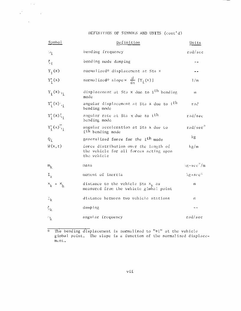
D E F I N I T I O N OF SYMBOLS AND U N I T S ( c o n t ' d )
Drf i n i t i o n U n i t s
W i bend ing I r e q u e n c y r a d / s e c
bend ing mode damp i n g - -
y i (x) normalized: ' d i s p l a c e m e n t a t S t a x - -
Y! ( x ) d no rma l i zed ' ; s l o p e = - [Yi ( x ) ]
1 dx 1 / m
y i ( x ) d i s p l a c e m e n t a t S t a x due t o it1' bend ing m mode
Y'. ( x ) r l i a n g u l a r t l i sp l acemen t a t S tn x due t o it[' r a cl 1
bend ing mode
Y k (x) a n g u l a r r a t e a t S t a x due t o it11 bcnd ing mode
Y ; ( x ) . ~ ~ a n g u l a r a c c e l e r a t i o n a t S t a x due t o r a d / s e c 2 i t h bend ing mode
I< g Q i g e n e r a l i z e d f o r c e f o r t h e ith mode
M(x, t ) f o r c e d i s t r i b u t i o n o v e r t h e l e n g t l l o f I<g/m t h e v e l l i c l e f o r a 1 1 Forces a c t i n g upon t h e v e l l i c l e
I k moment o f i n e r t i a kg-sec '
X - X k
d i s t a n c e t o t h e v e h i c l e S t a a s h
m measured from t h e v e h i c l e gimba L p o i n t
I
"k d i s t a n c e be tween two v e h i c l e s t a t i o n s m
r damping - - >k
L.'k a n g u l a r f r e q u e n c y r a d / s e c
' The bend ing d i s p l a c e m e n t i s n o r m a l i z e d t o "+1" a t t h e v e h i c l e g imba l p o i n t . The s l o p e i s a f u n c t i o n o f t h e n o r m a l i z e d d i s p l n c e - men t .
TECHNICAL MEMORANDUM X-53036
CONTROL THEORY HANDBOOK
SUMMARY
This r e p o r t p r e s e n t s under one cover , t h e e q u a t i o n s of mot ion and t h e b a s i c c o n t r o l theory a p p l i c a b l e t o s t a b i l i t y and response a n a l y s e s f o r a f l e x i b l e launch v e h i c l e , u s i n g a u n i f i e d c o o r d i n a t e sys tem and n o t a t i o n . To p r o v i d e some background and i n s i g h t i n t h e c o n t r o l of l a r g e f l e x i b l e b o o s t e r s moving through t h e ea . r th l s a tmosphere , f i v e o f t h e b a s i c c o n t r o l problems a r e d i s c u s s e d .
The f l i g h t s y s tem c o o r d i n a t e s and n o t a t i o n s a r e shown and t h e r i g i d body e q u a t i o n s a r e d e r i v e d f o r b o t h the p i t c h and yaw p lanes . A con- v e n t i o n a l c o n t r o l s y s tem is in t roduced which c o n t a i n s a p o s i t i o n g y r o , r a t e g y r o , a c c e l e r o m e t e r and a n g l e of a t t a c k meter . The g a i n s o f the c o n t r o l mechanism and t h e v e h i c l e pa ramete rs a r e r e l a t e d t o t h e f requency and damping of t h e r i g i d body. Both t h e " D r i f t Minimum" and "Load Mini- mum" c o n t r o l p r i n c i p l e s a r e developed.
The bending end s l o s h e q u a t i o n s a r e d e r i v e d by w r i t i n g t h e energy e x p r e s s i o n s and then a p p l y i n g ~ a g r a n ~ e ' s equa t ion . The method of com- put.ing bending modes and f r e q u e n c i e s f o r a f l e x i b l e body is shown f o r b o t h a s i m p l i f i e d cont inuous mass model and a lumped mass model.
The c o n s t r u c t i o n of a s y n t h e t i c wind p r o f i l e f o r c o n t r o l sys tem s t u d i e s u s i n g t h e 95 o r 99 p e r c e n t p r o b a b i l i t y of occur rence wind speed p r o f i l e and t h e 99 p e r c e n t p r o b a b i l i t y of occur rence wind s h e a r envelope is d i s c u s s e d and i l l u s t r a t e d , and t h e method f o r super imposing a g u s t on t h e s y n t h e t i c wind p r o f i l e is shown.
Block diagrams and t h e Laplace t r a n s f o r m a r e in t roduced t o r e l a t e t h e sys tem e q u a t i o n s i n a form which can be s t u d i e d i n terms of g e n e r a l feedback theory .
~ o u t h ' s s t a b i l i t y c r i t e r i o n , ~ u r w i t z ' s s t a b i l i t y c r i t e r i o n , r o o t l o c u s , f requency response methods, and Nyquis t c r i t e r i o n a r e d i s c u s s e d and a r e a p p l i e d t o a v e h i c l e c o n t a i n i n g one bending mode, a c o n t r o l f i l t e r and a n a c t u a t o r . The corresponding r o o t locus p l o t , Bode p l o t , Nyquis t p l o t and Nichols p l o t a r e drawn.
The b a s i c e lements of an example a d a p t i v e c o n t r o l s y s tem a r e d i s - cussed and i t s corresponding b lock diagram shown.
The appendices c o n t a i n t h e b lock diagram and t r a n s f e r f u n c t i o n s f o r s e v e r a l s e n s o r s and eng ine a c t u a t o r . A summary of the f l e x i b l e body e q u a t i o n s , i n c l u d i n g t h e e f f e c t s ,of engine i n e r t i a , bending motion and s l o s h mot ion, and a d e r i v a t i o n of t h e bending moment a t any s t a t i o n a long t h e v e h i c l e l o n g i t u d i n a l a x i s a r e a l s o g iven i n t h e appendix.
I. INTRODUCTION
During i n i t i a l d e s i g n phases of a v e h i c l e , numerous t r a j e c t o r i e s a r e computed u s i n g v a r i o u s degrees of s o p h i s t i c a t i o n . Almost i n v a r i a b l y i t is assumed t h a t t h e v e h i c l e is c o n t r o l l e d p e r f e c t l y and does n o t d e v i a t e from the d e s i r e d t r a j e c t o r y . Once the t r a j e c t o r y has been d e f i n e d , i t is then t h e job of t h e guidance and c o n t r o l groups t o s p e c i f y a means of c o n t r o l l i n g t h e v e h i c l e response i n o r d e r t o mini- mize e r r o r s i n p o s i t i o n and v e l o c i t y .
The o v e r a l l guidance f u n c t i o n is t o determine the p o s i t i o n and v e l o c i t y of t h e v e h i c l e and reduce t h e s e v a r i a b l e s t o a p i t c h and yaw command. These p i t c h and yaw commands a r e then t he r e f e r e n c e i n p u t s t o t h e c o n t r o l system.
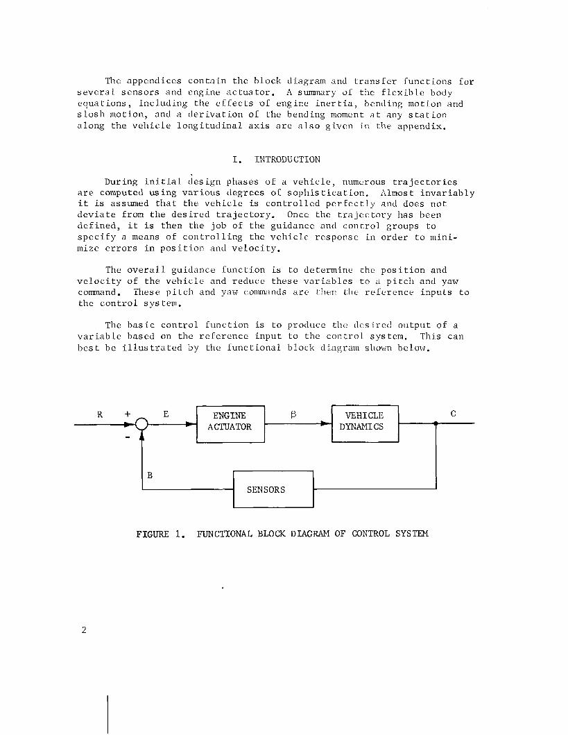
The b a s i c c o n t r o l [unc t ion is t o produce t h e d e s i r e d o u t p u t of a v a r i a b l e based on t h e r e f e r e n c e i n p u t t o the c o n t r o l system. This can b e s t be i l l u s t r a t e d by t h e f u n c t i o n a l b lock diagram shown below.
FIGURE 1. FUNCTIONAL BLOCK DIAGRAM O F CONTROL SYSTEM
@ VEHICLE C DYNAMICS T
R + E *
B
ENGINE ACTUATOR
SENSORS
Here t h e r e f e r e n c e i n p u t t o t h e c o n t r o l sys tem is R , and t h e d e s i r e d o u t p u t i s C. The sys tem c o n t a i n s t h e n e c e s s a r y s e n s o r s t o d e t e c t t h e d e s i r e d o u t p u t and may be i n t h e form of a t t i t u d e , a t t i t u d e r a t e s , e t c . The comparison between R and t h e feedback s i g n a l B r e s u l t s i n a n a c t u a t i n g s i g n a l E t h a t is t h e d i f f e r e n c e between t h e s e two q u a n t i t i e s . The a c t u a t i n g s i g n a l produces a n eng ine d e f l e c t i o n I ' ,
which c o r r e s p o n d i n g l y produces t h e d e s i r e d o u t p u t . This sys tem i s c a l l e d a c losed- loop c o n t r o l s y s tem s i n c e i t compares t h e o u t p u t and i n p u t q u a n t i t i e s t o m a i n t a i n t h e o u t p u t a t a d e s i r e d v a l u e .
The c o n t r o l s y s tem must c o n t a i n t h e n e c e s s a r y s e n s o r s t o d e t e c t t h e t r a n s l a t i o n a l , r o t a t i o n a l and v i b r a , t i o n a l mot ion of the v e h i c l e . The commonly employed s e n s o r s a r e t h e r a t e g y r o , p o s i t i o n g y r o , a c c e l e r - ometer and a n g l e - o f - a t t a c k mete r .
The t r a n s l a t i o n a l and r o t a t i o n a l mot ion a r e c o n v e n i e n t l y c o n t r o l l e d by d e f l e c t i n g the t h r u s t v e c t o r o r by use of movable s u r f a c e s on a e r o - dynamic f i n s . When aerodynamic c o n t r o l s u r f a c e s a r e u s e d , j e t vanes must be i n c l u d e d i n the r o c k e t eng ine e x h a u s t t o produce t h e c o n t r o l f o r c e u n t i l t h e dynamic p r e s s u r e b u i l d s up enough f o r the aerodynamic c o n t r o l s u r f a c e s t o become e f f e c t i v e . T h r u s t v e c t o r c o n t r o l i s more d e s i r a b l e than f i n s due t o a w e i g h t advantage. The v i b r a t i o n a l mot ion c o n s i s t s p r i m a r i l y of f u e l s l o s h and s t r u c t u r a l bending. Th i s mot ion can be e a s i l y s e n s e d , b u t is d i f f i c u l t t o c o n t r o l . The v i b r a t i o n a l n a t u r e of t h e v e h i c l e is s p e c i f i e d i n the e a r l y d e s i g n phases . The s t r u c t u r a l bending c h a r a c t e r i s t i c s a r c determined by t h e s t r u c t u r a l s t i f f n e s s and we igh t d i s t r i b u t i o n and canno t be s imply a 1 t e r e d once t h e v e h i c l e is manufactured. I;he f u e l s l o s h c h a r a c t e r is t i c s a r e l a r g e l y con- t r o l l e d by the t ank geometry , i n t e r n a l t ank b a f f l e s , and l o c a t i o n of p r o p e l l a n t t ank r e l a t i v e t o the c e n t e r of g r a v i t y of t h e v e h i c l e .
I n d e s i g n i n g a c o n t r o l sys tem f o r a f l e x i b l e b o o s t e r moving through t h e e a r t h ' s a tmosphere , t h e r e a r e g e n e r a l l y f i v e major problem a r e a s t h a t must be cons ide red .
1. D r i f t from r e f e r e n c e t r a j e c t o r y .
2. Aerodynamic loads .
3. S t r u c t u r a l bending feedback.
4. Fuel s l o s h .
5. Adequate r esponse t o d i s t u r b a n c e s .
The a u t h o r acknowledges Mrs. Joyce Harmon f o r h e r c o n t r i b u t i o n s t o t h e s e c t i o n on Methods of S t a b i l i t y Ana lys i s and M r . John L iv ings ton f o r h i s c o n t r i b u t i o n of the S e c t i o n on Wind R e p r e s e n t a t i o n .
11. DISCUSSION OF BASIC CONTROT, PiZOEI,I::IS
A. D r i f t From Reference T r a j e c t o r y
Tlle d r i f t of a v e h i c l e from a d e s i r c d t r a j c c t o r y can be d e t r i - menta l t o t h e o v e r a l l s u c c e s s of the miss ion . :lost miss ions depend on the accuracy w i t h which a v e h i c l e can p l a c e the payload i n t o a g i v e n volume of s p a c e w i t h a predetermined v e l o c i t y and d i r e c t i o n . S ince d r i f t d u r i n g t h e b o o s t l aunch phase r e s u l t s i n l a r g c p o s i t i o n e r r o r s a t l a t e r s t a g e s of f l i g h t , i t must be held t o an a b s o l u t e minimum.
The pr imary d i s t u r b a n c e a f i e c t ing d r i f t i s duc t o riinds a l o f t . Other i tems which cause d r i f t a r e t h r u s t m i s a l ignments , gyro d r i f t , c e n t e r of g r a v i t y v a r i a t i o n s , e t c . , b u t t h c s t a r c o r s icont lary impor- t a n c e compared t o wind d i s tu rbances .
Wind speeds can be of s l o ~ r l y va ry ing n a t u r t , sudden g u s t o r a combinat ion of bo th . For a p a r t i c u l a r lLiuncll s i t c , \rind speed d e s i g n p ro f i l c s a r e determined based on numerous rrind spcetl v c r s u s a 1 t i tude measurements. G e n e r a l l y , 95 o r 99 p e r c e n t ~ ~ i n d p r o i i l e s a r e used i n c o n t r o l sys tem d e s i g n and s p e c i f y the maximum wind spced v e r s u s a l t i - tude f o r a 95 o r 99 p e r c e n t p r o b a b i l i t y of occur rence . Also embedded g u s t s of v a r y i n g wave l e n g t h s , peak- to-peak amp1 i t u d e s and number of s u c c e s s i v e g u s t s can be superimposed on the wind speed p r o f i l e t o s t u d y the response of t h e c o n t r o l sys tem. The wind speed p r o f i l e s a r e con- s t r u c t e d by b u i l d i n g up t o the 95 p e r c e n t o r 99 p e r c e n t maximum v a l u e u s i n g t h e 99 p e r c e n t p r o b a b i l i t y of occur rence tlind s h e a r s a s s h o ~ m i n S e c t i o n V I I .
B. S t r u c t u r a l Loads
The aerodynamic f o r c e s imposed on a v e h i c l c dur ing i ts launch t r a j e c t o r y a f i e c t the dynamic response of the v e h i c l e t o c o n t r o l sys tern connnands. These f o r c e s may be s i g n i L i c a n t from time of l i f t o f f u n t i l the v e h i c l e s t a g e s o r emerges from the e f f e c t i v e atmospllere. The magni- tude of t h e s e f o r c e s a r e dependent on the a n g l e of a t t a c k , dynamic p r c s - s u r e , Mach number and t h e aerodynamic c h a r a c t e r i s t i c s of the v e h i c l e .
Although the dynamic p r e s s u r e ( q ) i s n o t l a r g e d u r i n g the i n i t i a l phase of f l i g h t , the p i t c h program i s u s u a l l y i n i t i a t e d d u r i n g t h i s phase r e s u l t i n g i n r e l a t i v e l y l a r g e a n g l e s of a t t a c k ( ) , and , hence a p p r e c i a b l e v a l u e s aq. These l o a d s caused by p i t c l ~ over command can be c r i t i c a l when a s t e p change i n commanded a t t i t u d e i s programmed. The loads can be g r e a t l y reduced by changing the progranuneci command t o a ramp f u n c t i o n . The aerodynamic load ing i s t y p i c a l l y most s e v e r e i n the

h i g h dynamic p r e s s u r e r e g i o n and occurs i n t h e range of a l t i t u d e s where winds and g u s t s a r e a t maximum i n t e n s i t y . It is o f t e n n e c e s s a r y i n the h i g h dynamic p r e s s u r e r e g i o n t o c o n s t r a i n t h e a n g l e of a t t a c k t o s m a l l v a l u e s s o t h a t s t r u c t u r a l d e s i g n l i m i t s a r e n o t exceeded.
The magni tude of the aerodynamic f o r c e is o b t a i n e d by i n t e g r a t - ing t h e d i s t r i b u t e d loads due t o p r e s s u r e and v i s c o s i t y a long t h e l e n g t h of t h e v e h i c l e . The r e s u l t a n t aerodynamic f o r c e i s then r e s o l v e d i n t o a normal f o r c e component p e r p e n d i c u l a r t o t h e l o n g i t u d i n a l a x i s and a d r a g component a l o n g t h i s a x i s . The normal f o r c e component a c t s a t t h e c e n t e r of p r e s s u r e and is one o f t h e pr imary i n f l u e n c e s a f f e c t i n g t h e t r a n s l a t i o n a l and r o t a t i o n a l mot ion of the v e h i c l e .
The l o c a t i o n of the c e n t e r of p r e s s u r e (c .p . ) r e l a t i v e t o t h e v e h i c l e c e n t e r of g r a v i t y (c .g . ) is a n impor tan t c o n s i d e r a t i o n a s i t p l a c e s a r equ i rement on t h e amount of c o n t r o l to rque n e c e s s a r y t o main- t a i n s t a b i l i t y and c o n t r o l of the v e h i c l e . The l o c a t i o n of the c ,p . i s p r i m a r i l y a f u n c t i o n of (1) t h e p o s i t i o n of the cones , f l a r e s and f i n s which make up t h e v e h i c l e c o n f i g u r a t i o n and ( 2 ) the Mach number.
Veh ic les hav ing the c.p. forward of the c.g. a r e ae rodynamica l ly u n s t a b l e and tend t o d e v i a t e from the d i r e c t i o n of t h e r e l a t i v e v e l o c i t y v e c t o r . I n t h e c a s e where l i m i t e d c o n t r o l to rque i s a v a i l a b l e , i t may b e n e c e s s a r y t o i n t r o d u c e f i n s a t the base of t h e v e h i c l e t o s h i r t the c.p. a f t . The v e h i c l e is ae rodynamica l ly s t a b l e when the c.p. is a f t o f t h e c.g. and tends t o a l i g n i t s l o n g i t u d i n a l a x i s a l o n g the r e l a t i v e v e l o c i t y v e c t o r . G e n e r a l l y , f i n s a r e n o t r e q u i r e d f o r t h i s c a s e .
I n t h e c a s e where loads become a problem, i t may be n e c e s s a r y t o i n c l u d e a load r e l i e f f e a t u r e i n t h e c o n t r o l s y s tem. Some load r e l i e f sys tems a r e des igned t o o p e r a t e on ly i n the r e g i o n where the l a t e r a l a c c e l e r a t i o n o r t h e p roduc t of a n g l e of a t t a c k and dynamic p r e s s u r e , L Z ~ , exceeds some p r e s e t l i m i t . The p r e s e t l i m i t i s dependent on t h e s t r u c t u r a l l i m i t ' a t i o n s of the v e h i c l e . Once t h e p r e s e t l i m i t i s exceeded, g a i n s a r e produced which a r e p r o p o r t i o n a l t o t h e l a t e r a l a c c e l e r a t i o n o r a n g l e of a t t a c k depending on the type of s e n s o r s u t i l i z e d . Th i s g a i n then becomes a dominant p a r t of t h e eng ine command s i g n a l .
The e f f e c t of t h i s added eng ine command s i g n a l is t o t u r n the v e h i c l e i n t o the wind, the reby reduc ing t h e a n g l e of a t t a c k and u l t i - ma te ly t h e eng ine d e f l e c t i o n i t s e l f . The d e c r e a s e of b o t h of t h e s e v a r i a b l e s r educes the bending moments which a r e d i r e c t l y p r o p o r t i o n a l t o t h e a n g l e of a t t a c k and t h e eng ine d e f l e c t i o n .
The most common load r e l i e f sys tem cons ide red i n the p a s t i s des igned t o b lend load minimum c o n t r o l g a i n s i n and o u t a s a f u n c t i o n of t ime. The t ime i n t e r v a l chosen g e n e r a l l y corresponds t o t h e maximum dynamic p r e s s u r e r e g i o n where aerodynamic l o a d i n g i s the most s e v e r e .
S i n c e load r e l i e 1 type c o n t r o l sys tems a t t e m p t t o a l i g n the v e h i c l e a t t i t u d e a l o n g t h e r e l a t i v e v e l o c i t y v e c t o r , t h e r e is no p re - dominant c o n t r o l of t h e v e h i c l e a t t i t u d e - . T h e r e f o r e , j. can assume l a r g e v a l u e s , and t h e v e h i c l e w i l l d r i f t away from the d e s i r e d t r a j e c t o r y . A p p l i c a t i o n of load r e l i e f type c o n t r o l is a c c e p t a b l e f o r s h o r t d u r a t i o n s provided a d e v i a t i o n from the d e s i r e d t r a j e c t o r y is p e r m i s s i b l e .
The bending loads imposed on the v e h i c l e s t r u c t u r e a r e depen- d e n t on the type of c o n t r o l law used s i n c e f o r each type of c o n t r o l law a d i f f e r e n t r e sponse i n eng ine gimbal a n g l e >, and hence ,,,, r e s u l t s . Appendix G shows t h a t t h c bending moment l o r a r i g i d v e h i c l e can be expressed a s
bending momcnt = (PI,:)(/ + (PI ' ,) / , .
The Form O F tlic r e sponse i s dependent on the type of feed- back inc luded i n t h e c o n t r o l law. For a n a t t i t u d e c o n t r o l law, the eng ine response c o n t a i n s s i g n a l s from botl i a p o s i t i o n gyro (>) and r a t e g y r o (.) and is of the Form ' = a,; + al$ w l ~ e r e a, i s t h e a t t i t u d e g a i n and a1 is t h e r a t e g a i n . I f a n g l e of a t t a c k ( J ) i s inc luded i n t h e con- t r o l law, t h e $ response i s a l i n e a r combination of ,,, $, and < i s of t h e form
where bo is t h e g a i n on a n g l e of a t t a c k . The method f o r de te rmin ing t h e g a i n s is d i s c u s s e d i n S e c t i o n IVD.
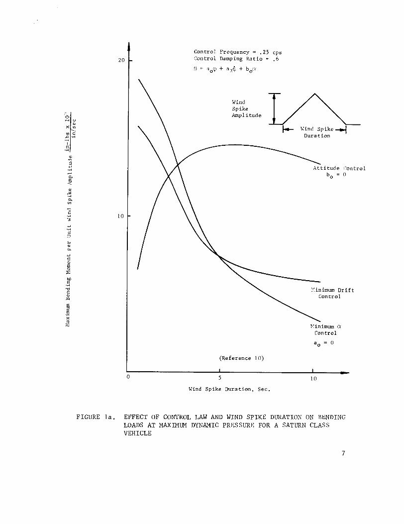
F i g u r e l a [ l o ] shows a comparison of t h e e r f e c t of t h r e e c o n t r o l laws on bending moments due t o a t r i a n g u l a r - s h a p c d wind p r o f i l e of u n i t ampl i tude . The maximum bending moment is p l o t t e d i n each c a s e v e r s u s the wind s p i k e d u r a t i o n f o r a t y p i c a l l y l a r g e v e l ~ i c l c a t the t ime of maximum dynamic p r e s s u r e . The wind s p i k e s of s h o r t d u r a t i o n i n t h i s f i g u r e correspond t o a h i g h s h e a r , h i g h fundamental f r equency wind. The longer d u r a t i o n wind s p i k e s correspond t o a low s l i ea r , low funda- menta l f r equency wind.
Cont ro l Frequency = .25 cps Cont ro l Damping R a t i o = .5
zi::e v\ Amplitude
Vind Spike 4 Dura t ion
\ A t t i t u d e : 'ontrol
bo = 0
Yinimum D r i f t + \ Cont ro l
Yinimum CY
Cont ro l
a, = 0
(Reference 10)
Wind Spike Dura t ion , Sec.
F I G U R E l a . E F F E C T O F CONTROL LAW AND WIND S P I K E DURATION ON B E N D I N G LOADS A T MAXIMUM DYNAMIC P R E S S U R E F O R A SATURN C L A S S V E H I C L E
I t is s e e n t h a t a t t i t u d e c o n t r o l produces 1 ower bending moments f o r s h o r t d u r a t i o n wind s p i k e s w h i l e bo th types of c o n t r o l employing ~i feedback a r e most e f f e c t i v e i n r educ ing Loads due t o long g r a d u a l wind s p i k e s .
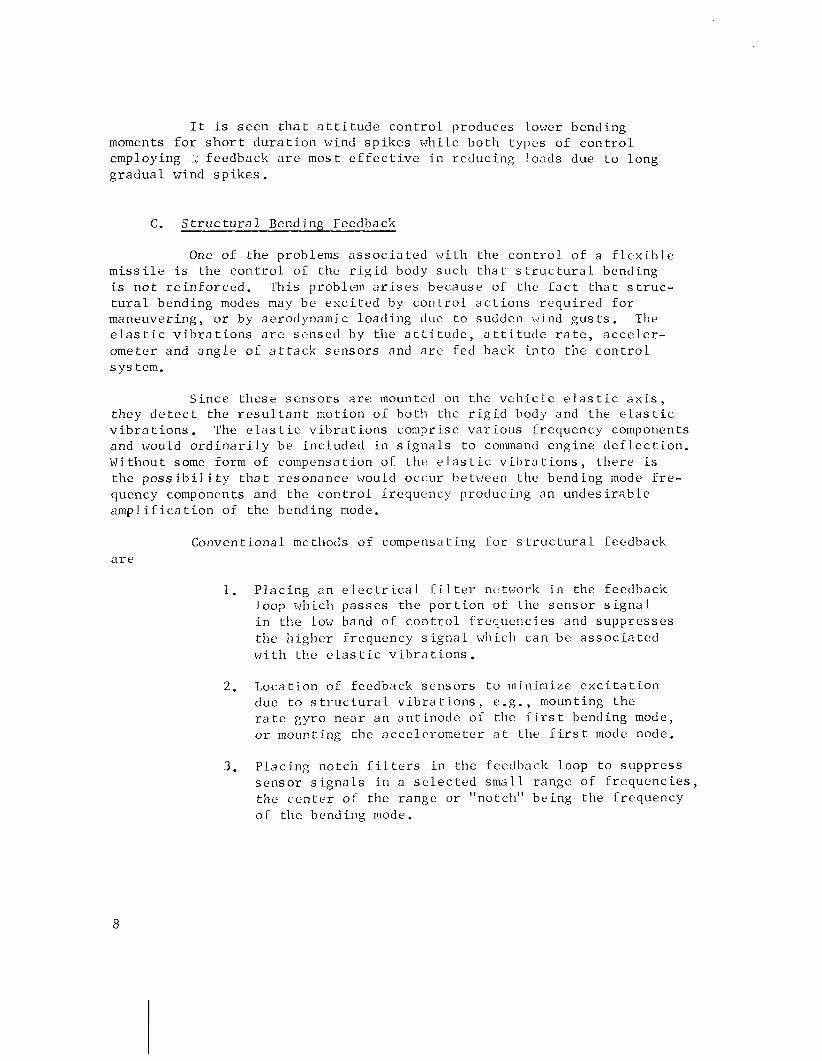
C. S t r u c t u r a 1 Bending Feedback
One o i the problems a s s o c i a t e d w i t h the c o n t r o l of a f l e x i b l e m i s s i l e is the c o n t r o l 01 the r i g i d body such t h a t s t r u c t u r a l bending is n o t r e i n f o r c e d . Th i s problem a r i s e s because of the f a c t t h a t s t r u c - t u r a l bending modes may be e x c i t e d by c o n t r o l a c t i o n s r e q u i r e d f o r maneuvering, o r by aerodynamic l o a d i n g due t o sudden wind g u s t s . The e l a s t i c v i b r a t i o n s a r e sensed by t h e a t t i t u d e , a t t i t u d e r a t e , a c c e l e r - ometer and a n g l e of a t t a c k s e n s o r s and a r e fed back i n t o the c o n t r o l s y s tem.
S i n c e t h e s e s e n s o r s a r e mounted on t h e v e h i c l e e l a s t i c a x i s , they d e t e c t the r e s u l t a n t mot ion of bo th the r i g i d body and t h e e l a s t i c v i b r a t i o n s . The e l a s t i c v i b r a t i o n s comprise v a r i o u s f requency components and would o r d i n a r i l y be inc luded i n s i g n a l s t o command eng ine d e f l e c t i o n . Without some form of compensation of t h e e l a s t i c v i b r a t i o n s , t h e r e is t h e p o s s i b i l i t y t h a t r e sonance would occur between the bending mode f r e - quency components and the c o n t r o l f requency producing a n u n d e s i r a b l e a m p l i f i c a t i o n of the bending mode.
Conventional methods of compensating f o r s t r u c t u r a l feedback a r e
1. P l a c i n g a n e l e c t r i c a l f i l t e r network i n the feedback loop which p a s s e s t h e p o r t i o n of the s e n s o r s i g n a l i n the low band of c o n t r o l f r e q u e n c i e s and s u p p r e s s e s t h e h i g h e r f requency s igna 1 x~llicll can be a s s o c i a t e d w i t h the e l a s t i c v i b r a t i o n s .
2. Loca t ion of feedback s e n s o r s t o minimize e x c i t a t i o n duc t o s t r u c t u r a l v i b r a t i o n s , e . g . , mounting t h e r a t e gyro nea r an a n t i n o d e of the f i r s t bending mode, o r mounting t h e a c c e l e r o m e t e r a t the First mode node.
3 . P l a c i n g notch f i l t e r s i n the feedback loop t o s u p p r e s s s e n s o r s i g n a l s i n a s e l e c t e d s m a l l range of f r e q u e n c i e s , t h e c e n t e r of the range o r "notch" be ing the f requency of t h e bending mode.
Anothe r i t e m of i m p o r t a n c e i n cons i t l e r i n g t h e s t r u c t u r a l bend- i n g of a v e h i c l e is o b t a i n i n g a c c u r a t e mode s h a p e s and s l o p e s o f t h e bend ing modes. Tile complex s t r u c t u r e (mu1 t i p l e t anks and e n g i n e c l us t e r s ) and l a r g e s i z e o f some b o o s t e r s make i t e x t r e m e l y d i f f i c u l t t o o b t a i n a c c u r a t e t h e o r e t i c a l and cxpe r imen ta 1 da t a t i e s c r i b i n g t h e v e l i i c l e ' s e l a s t i c p r o p e r t i e s . The modes s h a p e s a r e t k i c~ rc fo re i n a c c u r a t e l y k n o ~ i n and v a r y c o n s i d e r a b l y d u r i n g f l i g h t b e c a u s e o f rluss d i s t r i b u t i o n changes f rom p r o p e l l a n t d e p l e t i o n .
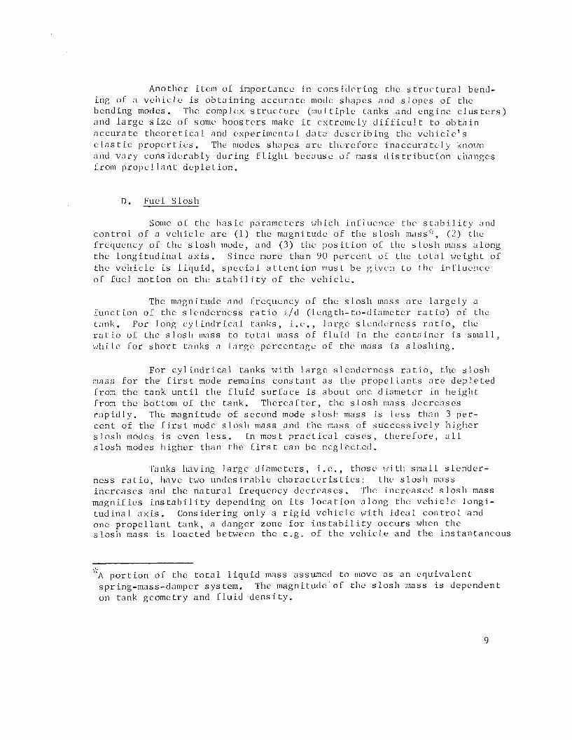
D. Fue l S l o s h
Some o f t h e b a s i c p a r a m e t e r s \ ~ h i c l i i n f l u c n c e tlie s t ' l b i l i t y and c o n t r o l o f a v e h i c l e a r e ( 1 ) t l ie magn i tude o f tl te s l o s h mass'::, ( 2 ) t h e f r e q u e n c y o f t h e s l o s h mode, and ( 3 ) t l ie p o s i t i o n oL tlic s l o s h mass a l o n g t h e l o n g i t u d i n a l a x i s . S i n c e more t h a n 90 p e r c e n t o f t h e t o t , ) 1 weigl l t o f t h e v e h i c l e is l i q u i d , s p e c i a 1 a t t e n t i o n mus t b e g i v e n t o t h e i n f l u e n c e o f f u e l mo t ion on t h c s t a b i l i t y o f t h e v e h i c l e .
The magn i tude and f r e q u e ~ i c y o f t h e s l o s l l mass a r e l a r g e l y a f u n c t i o n 01 t h e s 1 e n d e r n c . s ~ r a t i o ,,/d ( l c n g tlt- to-d i;lme t e r r a t i o ) of t h e t a n k . Fo r long c y l i n d r i c a l t a n k s , i . e . , l a r g e s l e n d e r n e s s r n t i o , tlte r a t i o o f t h e s l o s h mass t o t o t a l 111as.s O F f l u i d i n t l ~ e c o n t a i n e r is s a i a l l , ~ . r h i l e f o r s h o r t t a n k s a l a r g e p e r c c n t a g c o f t h e mass is s l o s l ~ i n g .
Fo r c y l i n d r i c a l t a n k s w i t h l a r g e s l e n d e r n e s s r a t i o , t h e s l o s h mass f o r t h e f i r s t mode r ema ins c o n s t a n t a s t h e p rope l l a n t s a r e d e p l e t e d f rom t h e t a n k u n t i l t h e f l u i d s u r f a c e i s a b o u t one d i a m e t e r i n h e i g l i t f rom t h e bo t tom o f t h e t ank . T h e r e a f t e r , t h e s l o s l ~ mass d e c r e : ~ s e s r a p i d l y . The magn i tude of s econd mode s l o s l l mass is l e s s t h a n 3 p e r - c e n t of t h e f i r s t mode s l o s h mass and t h e mass of s u c c e s s i v e l y h i g h e r s l o s h modes i s even l e s s . I n most p r a c t i c a l c a s e s , t h e r e f o r e , a11 s l o s h modes h i g h e r t h a n t h e f i r s t c an be n e g l e c t e d .
Tanks hav ing l a r g e diamc t e r s , i . c . , thosc. wit11 s m a l l s l e n d e r - n e s s r a t i o , have two u n d e s i r a b l e c h a r a c t e r i s t i c s : t h e s l o s h mass i n c r e a s e s and t h e n a t u r a l f r e q u e n c y d e c r e a s e s . 'I'he i n c r e a s e d s l o s h mass magni f i e s i n s t a b i l i t y depend ing on i ts l o c a t i o n a l ong t h e v c h i c l e l o n g i - t u d i n a l a x i s . C o n s i d e r i n g o n l y a r i g i d v e h i c l e w i t h i d e a l c o n t r o l and one p r o p e l l a n t t a n k , a d a n g e r zone f o r i n s t a b i l i t y o c c u r s when t h e s l o s h mass i s l o a c t e d be tween t h e c . g . o f t h e v e h i c l e and t h e i n s t a n t a n e o u s
-1-
"A p o r t i o n o f t h e t o t a l l i q u i d mass assumed t o move a s a n c q u i v a l e n t spr ing-mass-damper s y s tem. The magn i tude o f tlic s l o s h niass i s d e p e n d e n t on t a n k geome t ry and f l u i d d e n s i t y .
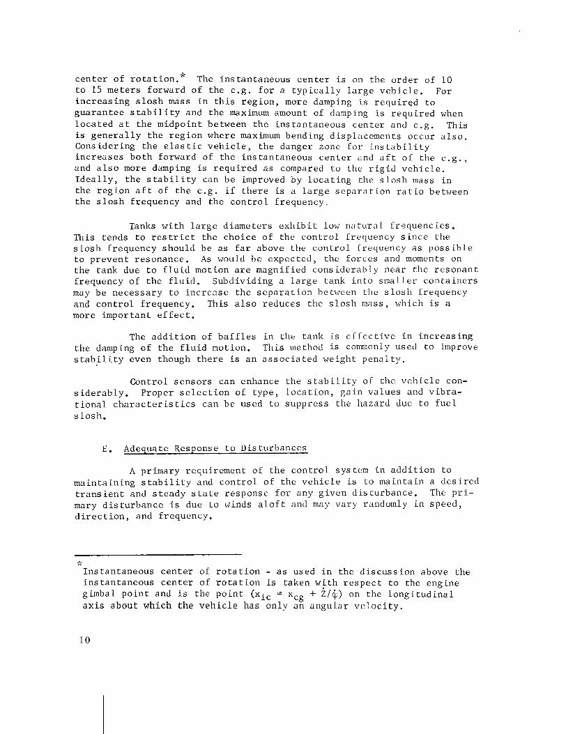
9; c e n t e r o f r o t a t i o n . The i n s t a n t a n e o u s c e n t e r i s on t h e o r d e r of 10 t o 15 m e t e r s forward of the c .g . f o r a t y p i c a l l y l a r g e v e h i c l e . For i n c r e a s i n g s l o s h mass i n t h i s r e g i o n , more damping i s r e q u i r e d t o g u a r a n t e e s t a b i l i t y and the maximum amount of damping i s r e q u i r e d when l o c a t e d a t t h e midpo in t between t h e i n s t a n t a n e o u s c e n t e r and c .g . This i s g e n e r a l l y t h e r e g i o n where maximum bending d i sp lacements occur a l s o . Cons i d e r ing t h e e l a s t i c v e h i c l e , t h e danger zone f o r i n s t a b i l i t y i n c r e a s e s b o t h forward of t h e i n s t a n t a n e o u s c e n t e r and a f t o f t h e c . g . , and a l s o more damping i s r e q u i r e d a s compared t o the r i g i d v e h i c l e . I d e a l l y , t h e s t a b i l i t y can be improved by l o c a t i n g the s l o s h mass i n t h e r e g i o n a f t of t h e c . g . i f t h e r e i s a l a r g e s e p a r a t i o n r a t i o between t h e s l o s h f requency and t h e c o n t r o l f r e q u e n c y .
Tanks w i t h l a r g e d i a m e t e r s e x h i b i t low nn t u r a l f r e q u e n c i e s . This t ends t o r e s t r i c t the c h o i c e of the c o n t r o l f requency s i n c e t h e s l o s h f requency shou ld be a s f a r above t h e c o n t r o l f r equency a s p o s s i b l e t o p r e v e n t r e sonance . As would be expec ted , the I o r c e s and moments on t h e t ank due t o f l u i d mot ion a r e magni f i ed c o n s i d e r a b l y n e a r the r e s o n a n t f r equency of t h e f l u i d . Subd iv id ing a l a r g e tank i n t o s m a l l e r c o n t a i n e r s may be n e c e s s a r y t o i n c r e a s e t h e s e p a r a t i o n between t l ~ e s l o s h f requency and c o n t r o l f requency. This a l s o reduces t h e s l o s h mass, which i s a more impor tan t e f f e c t .
The a d d i t i o n of b a f f l e s i n the t a n k i s e f L e c t i v e i n i n c r e a s i n g t h e damping of t h e f l u i d motion. Th i s method i s comn~only used t o improve s t a b i l i t y even though t h e r e is a n a s s o c i a t e d we igh t p e n a l t y .
Con t ro l s e n s o r s can enhance t h e s t a b i l i t y of t h e v e h i c l e con- s i d e r a b l y . P roper s e l e c t i o n of type , l o c a t i o n , g a i n v a l u e s and v i b r a - t i o n a l c h a r a c t e r i s t i c s can be used t o s u p p r e s s the haza rd due t o f u e l s l o s h .
E. Adequate Response t o Dis tu rbances
A pr imary requ i rement of t h e c o n t r o l sys tem i n a d d i t i o n t o m a i n t a i n i n g s t a b i l i t y and c o n t r o l o f t h e v e h i c l e is t o m a i n t a i n a d e s i r e d t r a n s i e n t and s t e a d y s t a t e r e sponse f o r any g i v e n d i s t u r b a n c e . The p r i - mary d i s t u r b a n c e i s due t o winds a l o f t and may v a r y randomly i n speed , d i r e c t i o n , and f requency.
-3-
I n s t a n t a n e o u s c e n t e r of r o t a t i o n - a s used i n t h e d i s c u s s i o n above t h e i n s t a n t a n e o u s c e n t e r of r o t a t i o n is taken w i t h r e s p e c t t o the eng ine gimbal p o i n t and i s t h e p o i n t (xi, = x + i/@) on the l o n g i t u d i n a l c g a x i s a b o u t which t h e v e h i c l e has on ly a n a n g u l a r v e l o c i t y .
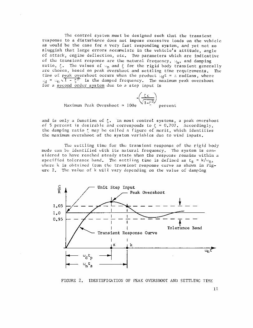
The c o n t r o l sys tem must be des igned s u c h t h a t t h e t r a n s i e n t r e sponse t o a d i s t u r b a n c e does n o t impose e x c e s s i v e l o a d s on the v e h i c l e a s would b e t h e c a s e f o r a v e r y f a s t r e spond ing sys tem, and y e t n o t s o s l u g g i s h t h a t l a r g e e r r o r s accumulate i n t h e v e h i c l e ' s a t t i t u d e , a n g l e o f a t t a c k , eng ine d e f l e c t i o n , e t c . Two paramete r s which a r e i n d i c a t i v e of the t r a n s i e n t r e sponse a r e t h e n a , t u r a l f r equency , wn, and damping r a t i o , 5 . The v a l u e s of ::, and i; f o r t h e r i g i d body t r a n s i e n t g e n e r a l l y a r e chosen, based on peak o v e r s h o o t and s e t t l i n g t ime r e q u i r e m e n t s . The t ime of peak o v e r s h o o t occurs when t h e p r o d u c t ~ ~ d t = n r a d i a n s , where
- ~d - ~~1 - c2' is the damped f requency. The maximum peak o v e r s h o o t f o r a second o r d e r s y s tem due t o a s t e p i n p u t is
Maximum Peak Overshoot = lOOe p e r c e n t
and is o n l y a f u n c t i o n of 5 . l n most c o n t r o l s y s tems, a peak o v e r s h o o t of 5 p e r c e n t i s d e s i r a b l e and cor responds t o ( = 0.707. Accord ing ly , t h e damping r a t i o 5 may be c a l l e d a f i g u r e of m e r i t , which i d e n t i f i e s t h e maximum o v e r s h o o t of t h e sys tem v a r i a b l e s due t o wind i n p u t s .
The s e t t l i n g t ime f o r t h e t r a n s i e n t r e sponse of t h e r i g i d body mode can be i d e n t i f i e d w i t h i ts n a t u r a l f requency. The sys tem is con- s i d e r e d t o have reached s t e a d y s t a t e when t h e response remains w i t h i n a s p e c i f i e d t o l e r a n c e band. The s e t t l i n g t ime is d e f i n e d a s ts = k/i8in, where k i s o b t a i n e d from t h e t r a n s i e n t r e sponse curve a s s h o ~ m i n Fig- u r e 2. The v a l u e of k w i l l v a r y depending on t h e v a l u e of damping
Unit S t e p I n p u t
- -
FIGURE 2. IDENTIFICATION OF PEAK OVERSHOOT AND SETTLING TIME
r a t i o (0 o r n a t u r a l f requency ( ~ 1 ~ ) chosen. For a g i v e n [I,,, t he s e t t l i n g t ime becomes l o n g e r a s f' is d e c r e a s e d due t o t h e l a r g e r o v e r s h o o t s i n t h e response . The e f f e c t of wn on s e t t l i n g t ime can b e s t be s e e n by comparing two d i f f e r e n t s y s tems hav ing t h e same <. Tf the response shown i n F igure 2 , which is p l o t t e d i n nondimens i o n a l c o o r d i n a t e s , a p p l i e s t o two d i f f e r e n t sys tems having the same 5 , then t h e sys tem having t h e l a r g e s t n a t u r a l f r equency w i l l l ~ a v e the s h o r t e s t s e t t l i n g t ime .
The n a t u r a l f requency of t h e r i g i d body mode s t ~ o u l d be k e p t s u f f i c i e n t l y low s o t h a t t h e r e is a wide s e p a r a t i o n w i t h f r e q u e n c i e s of o t h e r degrees of freedom. G e n e r a l l y , t h e f i r s t s l o s h mode f requency e s t a b l i s h e s t h e upper l i m i t on t h e c o n t r o l f requency of the r i g i d body mode s i n c e t h e f i r s t s l o s h mode c o n t a i n s t h e lowes t f r equency component a s compared t o t h e o t h e r degrees of freedom. The c o n t r o l f r equency f o r t h e r i g i d body mode shou ld be s e l e c t e d such t h a t i t is s u f f i c i e n t l y below the f i r s t s losl l mode Crequency s o t h a t s t r o n g coup l ing does n o t e x i s t and y e t n o t s o low t h a t long s e t t l i n g t imes r e s u l t .
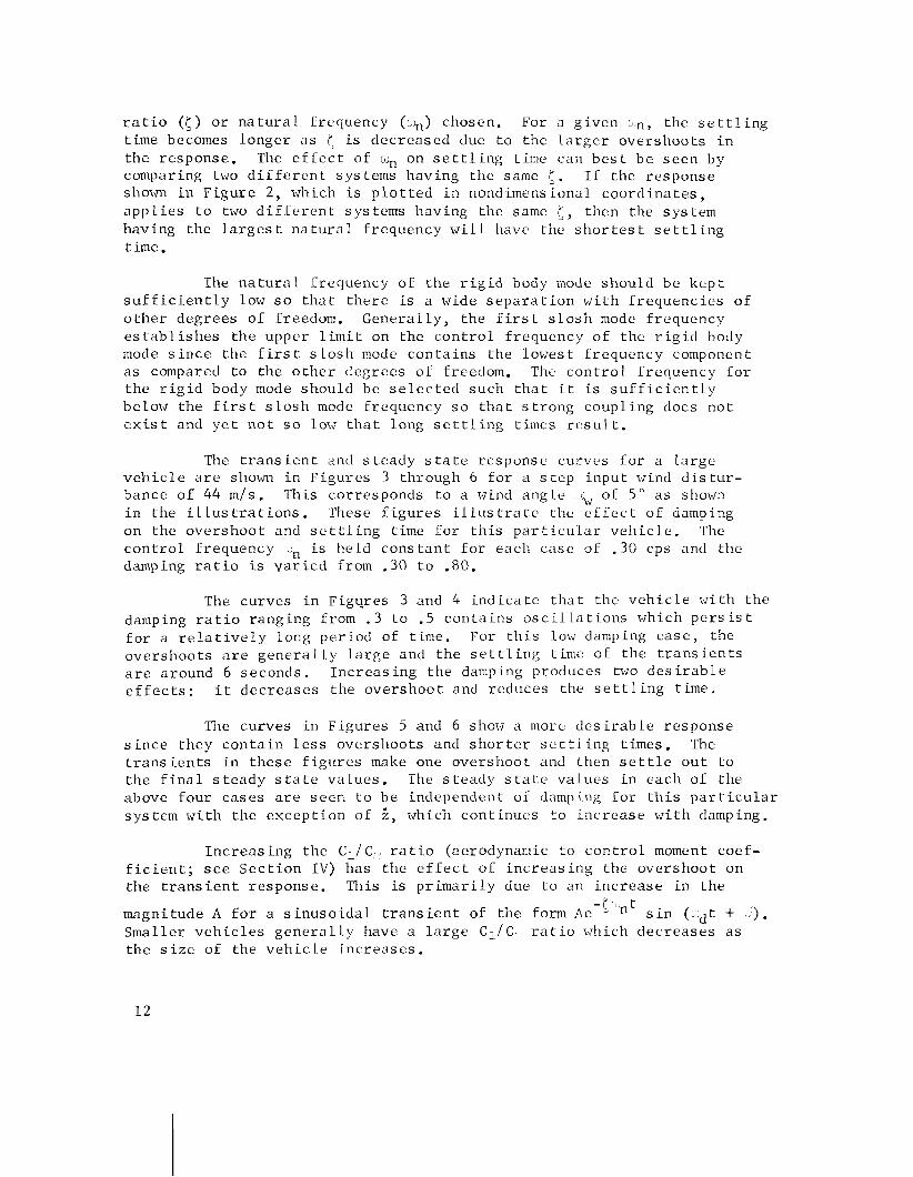
The t r a n s i e n t and s teady s t a t e r e sponse curves f o r a l a r g e v e h i c l e a r e shown i n F i g u r e s 3 through 6 f o r a s t e p i n p u t wind d i s t u r - bance o f 44 m/s. This co r responds t o a wind a n g l e ~t, of 5 " a s shown i n t h e i l l u s t r a t i o n s . These I i g u r e s i l l u s t r a t e the e f f e c t of damping on t h e o v e r s h o o t and s e t t l i n g time f o r t h i s p a r t i c u l a r v e h i c l e . The c o n t r o l f r equency ,n is held c o n s t a n t f o r each c a s c of .30 cps and t h e damping r a t i o is v a r i e d from .30 t o .80.
The curves i n F i g u r e s 3 and 4 i n d i c a t e t h a t t h e v e h i c l e w i t h t h e damping r a t i o r ang ing from . 3 t o .5 c o n t a i n s o s c i l l a t i o n s which p e r s i s t f o r a r e l a t i v e l y long pe r iod of t ime. For t h i s low damping c a s e , the o v e r s h o o t s a r e g e n e r a l l y l a r g e and the s e t t l i n g time of t h e t r a n s i e n t s a r e around 6 seconds . I n c r e a s i n g t h e damping produces two d e s i r a b l e e f f e c t s : i t d e c r e a s e s the overshoo t and reduces the s e t t l i n g t ime.
The curves i n F igures 5 and 6 show a morc d e s i r a b l e r esponse s i n c e t h e y c o n t a i n l e s s o v e r s l ~ o o t s and s h o r t e r s c t t l ing t imes . The t r a n s i e n t s i n t h e s e f i g u r e s make one overshoo t and then s e t t l e o u t t o t h e f i n a l s t e a d y s c a t e v a l u e s . The s t e a d y s t a t e v a l u e s i n each of the above f o u r c a s e s a r e s e e n t o be independent oT clamping f o r t h i s p a r t i c u l a r s y s tem w i t h t h e e x c e p t i o n of 5 , which c o n t inucs t o i n c r e a s e w i t h damping.
I n c r e a s i n g t h e C1/ C, , r a t i o (aerodynamic t o c o n t r o l moment coef - f i c i e n t ; s e e S e c t i o n I V ) has t h e e f f e c t of i n c r e a s i n g the overshoo t on the t r a n s i e n t r e sponse . This i s p r i m a r i l y due t o a n i n c r e a s e i n the
magni tude A f o r a s i n u s o i d a l t r a n s i e n t of' t h e form Ae -' h t s i n ( r d t + ). Smal le r v e h i c l e s g e n e r a l l y have a l a r g e C, /C r a t i o which d e c r e a s e s a s t h e s i z e of t h e v e h i c l e i n c r e a s e s .

F I G U R E 3. T R A N S I E N T R E S P O N S E CURVES F O R A R I G I D BODY DAMPING O F . 3 AND FREQUENCY O F . 3 C P S
11 2 4 h R t o 1 2
1 I , 1 ,
F I G U R E 4 . T R A N S I E N T R E S P O N S E CURVES F O R A K I G I D BODY DAMPING O F .5 AND FREQUENCY O F . 3 C P S
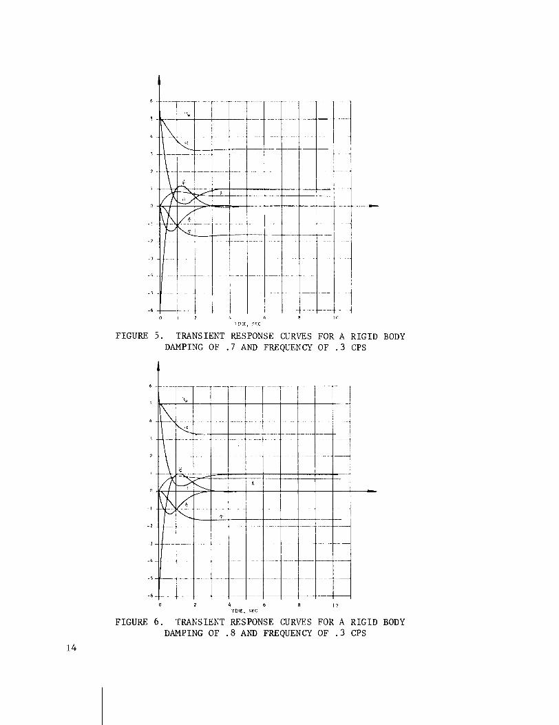
FIGURE BODY
0 2 4 b 8 10 r m E , CFC
FIGURE 6 . TRANSIENT RESPONSE CURVES FOR A R I G I D BODY DAMPING OF . 8 AND FREQUENCY O F . 3 CPS
The n a t u r a l f r equency of t h e r i g i d body mode shou ld b e wide ly s e p a r a t e d w i t h f r e q u e n c i e s of o t h e r degrees of freedom. The gu idance mode e s t a b l i s h e s the lowes t f r equency e x i s t i n g i n t h e sys tem. The p e r i o d of t h i s mode i s s e v e r a l o r d e r s of magnitude longer t h a n t h e con- t r o l and e l a s t i c modes. The c o n t r o l mode i n t h i s c a s e can be c o n s i d e r e d a s uncoupled from t h e gu idance mode. The upper bound on c o n t r o l f r e - quency is e s t a b l i s h e d by t h e f i r s t s l o s h mode f requency o r t h e f i r s t bending mode f requency whichever is l e s s . The c o n t r o l f r equency f o r t h e r i g i d body shou ld b e chosen s o t h a t i t is s u f f i c i e n t l y below t h e upper bound f requency t o reduce mode coup l ing e i f e c t s , and y e t n o t s o low t h a t long s e t t l i n g t imes r e s u l t .
111. FLIGHT SYSTEM COORDINATES
The o r i e n t a t i o n of the m i s s i l e axes i n i n e r t i a l space is shown i n F i g u r e 7 .
FIGURE 7 . VEHICLE COORDINATE SYSTEM
The XYZ-coordinate sys tem is d e f i n e d r e l a t i v e t o the r e f e r e n c e t r a - j e c t o r y a s f o l l o w s : The X a x i s i s d i r e c t e d a long t h e d e s i r e d v e l o c i t y v e c t o r V, the Z a x i s is normal t o t h e p l a n e of the d e s i r e d t r a j e c t o r y , and t h e Y a x i s is i n r igh t -hand r e l a t i o n t o X and Z . The v e h i c l e o r i e n - t a t i o n is d e f i n e d by t h e xyz-coord ina tes where t h e x a x i s is d i r e c t e d
a l o n g t h e v e h i c l e l o n g i t u d i n a l a x i s , t h e y a x i s is d i r e c t e d a long the v e h i c l e yaw a x i s , and t h e z a x i s is d i r e c t e d a l o n g the v e h i c l e p i t c h a x i s . The o r i g i n of the xyz-coord ina te s y s tem is Located a t the v e h i c l e c.g.
The p i t c h a t t i t u d e ip and yaw a t t i t u d e : d e f i n e the d i r e c t i o n of Y
the m i s s i l e l o n g i t u d i n a l a x i s i n the XYZ-coordinates . rhese a n g l e s a r e assumed s m a l l s o t h a t t h e e q u a t i o n s of motion may be 1 i n e a r i z e d .
The d e g r e e of freedom a long t h e X a x i s is e l i m i n a t e d by a l l o w i n g the c o o r d i n a t e sys tem t o a c c e l e r a t e w i t h t h a t of t h e v e h i c l e c.g. i n t h e X d i r e c t i o n . The e q u a t i o n s of mot ion, t h e r e f o r e , wi l l a l l o w o n l y a c c e l e r a t i o n s r e l a t i v e t o t h e XYZ-coordinate sys tem i n t h e Y and Z d i r e c - t i o n s . The o r i e n t a t i o n of t h e c o o r d i n a t e s y s tern is chosen i n t h i s man- n e r s i n c e we a r e on ly i n t e r e s t e d i n t h e a t t i t u d e d e v i a t i o n s and p o s i t i o n and v e l o c i t y d e v i a t i o n s from the r e f e r e n c e t r a j c c t o r y .
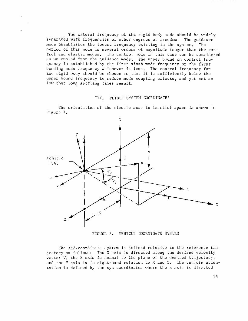
F i g u r e 8 below shows t h e o r i e n t a t i o n of the v e h i c l e r e l a t i v e t o t h e r e f e r e n c e t r a j e c t o r y and t h e i n e r t i a l c o o r d i n a t e s XY. This is t h e geometry used i n making a f i x e d t ime p o i n t s t u d y f o r a c o n t r o l sys tem i n t h e p i t c h p l a n e . I n t h i s c a s e , i t is penn i s s i b l e t o r educe t h e
R P ~ . n i r e c t ion
Reference D i r e c t i o n a t Launch
Veh ic le C.G.
l'a1:gent t o Reference T r a j e c t o r y
-- Reference T r a j e c t o r y
/ / / / / / / / / / / I / / / / / / / / / / / / / / / / I / ' / /I//// //
FIGURI', 8. PITCH PLANE GEOMETRY

problem t o two climens ions s i n c e t h e c r o s s coupl ing be tween t h e yaw p lane and p i t c h p lane i s assumed s m a l l . 12lso shown i n t h i s f i g u r e a r e the a n g l e s ,! and Xc , where kc is the a t t i t u d c conmiandcd by t l ~ c p i t c h program and X i s the a c t u a l a t t i t u d c of tlie v e l ~ i c l e . The a n g l e i s o b t a i n e d from tlie r e f e r e n c e t r a j e c t o r y and is i n p u t t o t l ~ e v e h i c l e a u t o p i l o t . ,\s can be s e e n from F i g u r e 8 , t h e p i tch , a t t i t u d e - = . y p i ~ - . The v a r i a b l e - is used i n the c o n t r o l s y s tcm e q u a t i o n s r'ltlicr than <, and s i n c e i t
P r e p r e s e n t s a s m a l l a n g u l a r d e v i a t i o n from t11c d e s i r e d d i r c c t i o n s X.
F i g u r e 9 below shows the o r i e n t a t i o n of tlic v e l i i c l c r e l a t i v e t o the yaw p l a n e of thc r c f c r e n c c t r a j e c t o r y .
FIGURE 9. YAiJ PLANE GEOMETKY
P lane of j Reference T r a j e c t o r y
Again the problem i s reduced t o two-dimensional motion i n the yaw p l a n e by assuming the c r o s s coupl ing betwcen t h e p i t c h p l a n e and yaw p lane is s m a l l .
i L - b x
I V . R I G I D BODY EQUATIONS
A . D e r i v a t i o n of Equat ions
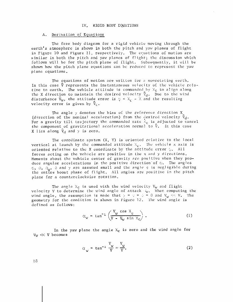
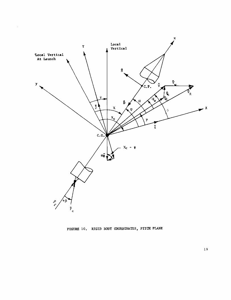
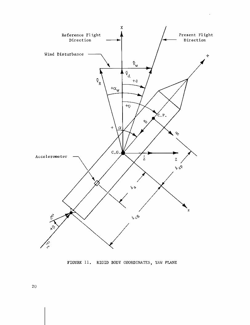
The f r e e body diagram f o r a r i g i d v e h i c l e moving through the e a r t h ' s a tmosphere is shown i n b o t h the p i t c h and yaw p l a n e s of f l i g h t i n F i g u r e 1 0 and F i g u r e 11, r e s p e c t i v e l y . The e q u a t i o n s of mot ion a r e s i m i l a r i n b o t h t h e p i t c h and yaw p l a n e s of f l i g h t ; t h e d i s c u s s i o n which f o l l o w s w i l l be f o r t h e p i t c h p lane of f l i g h t . Subsequen t ly , i t w i l l be shown how t h e p i t c h p lane e q u a t i o n s can be reduced t o r e p r e s e n t t h e yaw p lane e q u a t i o n s .
The e q u a t i o n s of mot ion a r e w r i t t e n f o r a nonro ta t i n g e a r t h . I n t h i s c a s e r e p r e s e n t s t h e i n s t a n t a n e o u s v e l o c i t y of t h e v e h i c l e r e l a - t i v e t o e a r t h . The v e h i c l e a t t i t u d e i s commanded by Xc t o a l i g n a l o n g t h e X d i r e c t i o n t o m a i n t a i n t h e d e s i r e d v e l o c i t y V d . Due t o the wind d i s t u r b a n c e fw, t h e a t t i t u d e e r r o r is (i = Xc - X and the r e s u l t i n g v e l o c i t y e r r o r is g i v e n by ic.
The a n g l e y deno tes t h e b i a s of t h e r e f e r e n c e d i r e c t i o n X ( d i r e c t i o n of the nominal a c c e l e r a t i o n ) from t h c $ e s i r e d v e l o c i t y id. For a g r a v i t y t i l t t r a j e c t o r y t h e commanded r a t e LC i s a d j u s t e d t o c a n c e l t h e component of g r a v i t a t i o n a l a c c e l e r a t i o n normal t o V. I n t h i s c a s e X l i e s a l o n g td and y is z e r o .
The c o o r d i n a t e sys tem (X, Y ) is o r i e n t e d r e l a t i v e t o t h e l o c a l v e r t i c a l a t l aunch by t h e commanded a t t i t u d e L C . The v e h i c l e x a x i s is o r i e n t e d r e l a t i v e t o the X c o o r d i n a t e by t h e a t t i t u d e e r r o r b. A l l f o r c e s a c t i n g on t h e v e h i c l e a r e p o s i t i v e i n t h e x and y d i r e c t i o n s . Moments a b o u t t h e v e h i c l e c e n t e r of g r a v i t y a r e p o s i t i v e when they pro- duce a n g u l a r a c c e l e r a t i o n s i n t h e pos i t i v e d i r e c t i o n ' of $. The a n g l e s
v, a, %, j and y a r e assumed s m a l l and t h e a n g l e is n e g l i g i b l e d u r i n g t h e e n t i r e b o o s t phase of f l i g h t . A l l a n g l e s a r e p o s i t i v e i n the p i t c h p l a n e f o r a coun te rc lockwise r o t a t i o n .
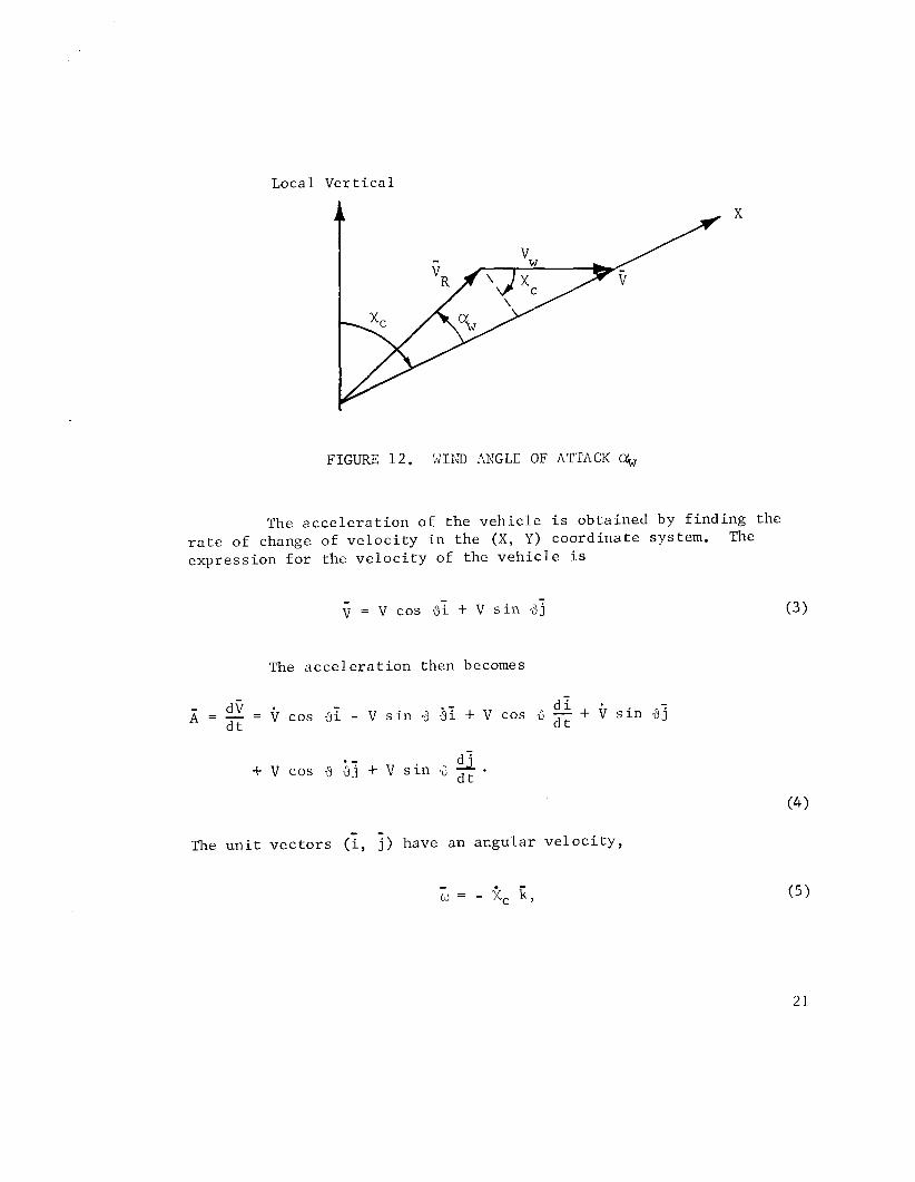
The a n g l e Xc i s used w i t h t h e wind v e l o c i t y V, and f l i g h t v e l o c i t y V t o de te rmine the wind a n g l e of a t t a c k When computing the wind a n g l e , t h e assumpt ion i s made t h a t 7 = 1 = . = 0 and Vw <.- V. The geometry f o r t h e c o n d i t i o n is shown i n F i g u r e 1 2 . The wind a n g l e i s d e f i n e d a s f o l l o w s :
v cos Xc ah, = tan-' (v - vw s i n Xc >
I n t h e yaw p l a n e t h e a n g l e Xc i s z e r o and t h e wind a n g l e f o r Vw << V becomes
X
Zoca 1 Ver t ice 1 At Launch
Y
X
B P 1 Fc
FIGURE 10. RIGZD BODY COORDINATES, PITCH PLANE
Reference Flight Present Flight Direction
Wind Disturbance h
Accelerometer
FIGURE 11. RIGID BODY COORDINATES, YAW PLANE
Local Ver t i ca l
FIGURE 1 2 . W I N D ANGLE OF ATTACK CY,
The a c c e l e r a t i o n of the v e h i c l e i s obtained by f ind ing the r a t e of change of v e l o c i t y i n the ( X , Y ) coord ina te system. The
expression f o r the v e l o c i t y of the v e h i c l e i s
= v cos 8; + v s i n 33
The a c c e l e r a t i o n then becomes
- d ? d i A = - = cos 3 1 - V s i n 9 4; + V cos 3 + $ s i n d j
d t
Q . + v cos -3 i j + v s i n 4 d t
- - The u n i t v e c t o r s ( i , j ) have an acgular v e l o c i t y ,
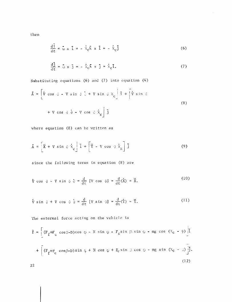
S u b s t i t u t i n g e q u a t i o n s (6) and ( 7 ) i n t o e q u a t i o n (4)
r J, = cos 4 - v s i n 3 1 + V s i n ; x, i + riJ s i n 3 L I - i
where e q u a t i o n (8) can be w r i t t e n a s
s i n c e t h e fo l lowing terms i n e q u a t i o n (8) a r e
d d . .. cos J - V s i n 4 -3 = - [ V cos 01 = dt(X) = X.
d t
d d . . . s i n -3 + V cos -2 4 = - [ V s i n 01 = -(Y) = Y .
d t d t
The e x t e r n a l f o r c e a c t i n g on t h e v e h i c l e i s
- r I - f = (F +F cos p-D)cos y, - N s i n - Fcs i n 3 . s i n - mg cos (Xc - Ij) ii I f c i
r 1 -
+ (F +F c o s p - ~ ) s i n q, + N cos v + F, s i n 13 cos q - mg s i n (Xc - 4) lj. I f c i
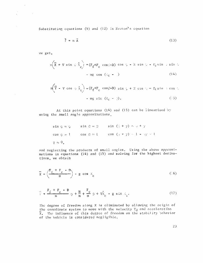
S u b s t i t u t i n g e q u a t i o n s (9 ) and ( 1 2 ) i n s ewton ' s e q u a t i o n
we g e t ,
. \ + v s i n x 1 = ( F +F cost!-^) cos ; - S s i n ; - resin S i n 1
C/ f c
- mg c o s (/.c - ) ( 1 4 )
c< - v 2 ') =(Ff+F cosp-D) s i n ; + r; cos -> + Fc s i n , c o s *2 T \ C/
C
- mg s i n (;Cc - !I. ( 1 5 )
A t t h i s p o i n t e q u a t i o n s (14) and (15) can b e l i n e a r i z e d b y u s i n g t h e s m a l l a n g l e a p p r o x i m a t i o n s ,
s i n cy % q s i n 13 = s i n ( ? + 7 ) - LI + ;
c o s q, = 1 c o s r) =- 1 c o s (, + 7 ) -- 1 - -7 . 1
and n e g l e c t i n g t h e p r o d u c t s o f s m a l l a n g l e s . Using t h e above a p p r o x i - m a t i o n s i n e q u a t i o n s (14) and (15) and s o l v i n g f o r t h e h i g h e s t d e r i v a - t ives , we ob t a i n
. F f + F c - D N c , - I - ( r + - + - p + V X c - g s i n ,.:.
m m m C
The d e g r e e o f f reedom a l o n g X is e l i m i n a t e d by a l l o w i n g the o r i g i n o f t h e c o o r d i n a t e s y s t e m t o move w i t h t h e v e l o c i t y Vd and a c c e l e r a t i b n . . X. The i n £ l u e n c e o f t h i s d e g r e e of freedom on t h e s t a b i l i t y b e h a v i o r o f t h e v e h i c l e i s c o n s i d e r e d n e g l i g i b l e .
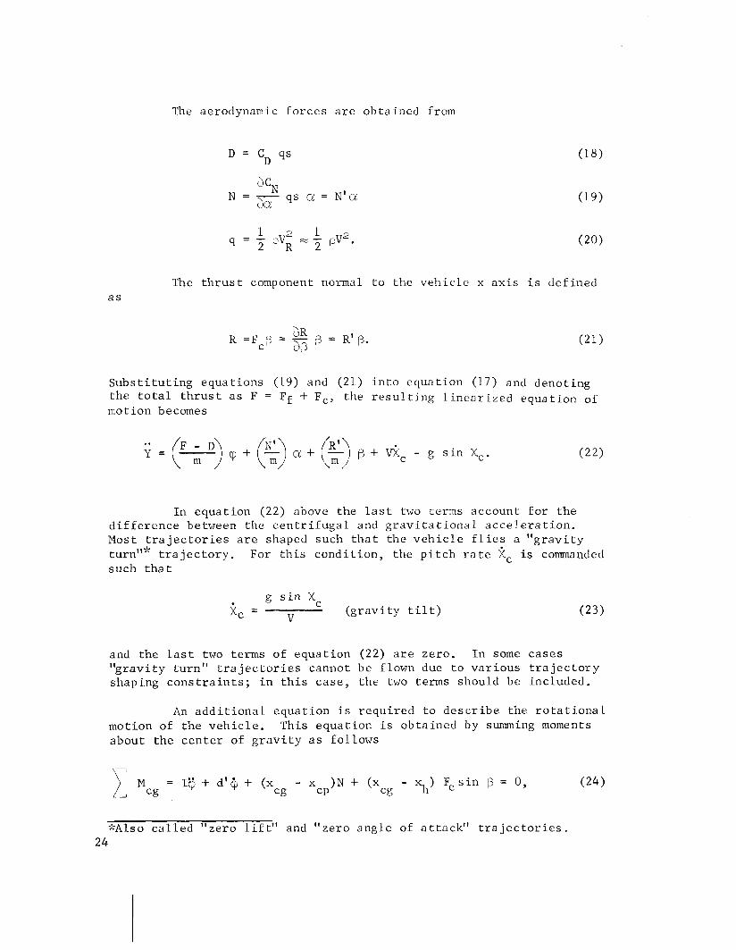
The aerodynamic f o r c e s a r e ob ta ined from
The t h r u s t component normal t o t h e v e h i c l e s a x i s i s clef ined
S u b s t i t u t i n g equa t ions (19) and (21) i n t o e q u a t i o n ( 1 7 ) and deno t ing t h e t o t a l t h r u s t a s F = Ff + Fc, the r e s u l t i n g l i n e a r i z e d equa t ion of motion becomes
( ' - D ) ~ + ( % ) a+($) p + c.;c - g s i n ic. Y=jm
I n e q u a t i o n (22) above t h e l a s t two terms account f o r t h e d i f f e r e n c e between t h e c e n t r i f u g a l and g r a v i t a t i o n a l a c c e l e r a t i o n . Most t r a j e c t o r i e s a r e shaped such t h a t t h e v e h i c l e f 1 i e s a " g r a v i t y
t r a j e c t o r y . For t h i s c o n d i t i o n , t h e p i t c h r a t e kc i s commanded such tha t
g s i n X C
Xc = v ( g r a v i t y t i l t )
and t h e l a s t two terms of e q u a t i o n (22) a r e ze ro . I n some c a s e s 11 g r a v i t y t u r n " t r a j e c t o r i e s cannot be flown due t o v a r i o u s t r a j e c t o r y shaping c o n s t r a i n t s ; i n t h i s c a s e , t h e two terms should be included.
An a d d i t i o n a l e q u a t i o n i s r e q u i r e d t o d e s c r i b e the r o t a t i o n a l mot ion of t h e v e h i c l e . This e q u a t i o n i s ob ta ined by summing moments abou t t h e c e n t e r of g r a v i t y a s fo l lows
;\Also c a l l e d " z e r o l i f t " and "ze ro ang le of a t t a c k " t r a j e c t o r i e s . 2 4
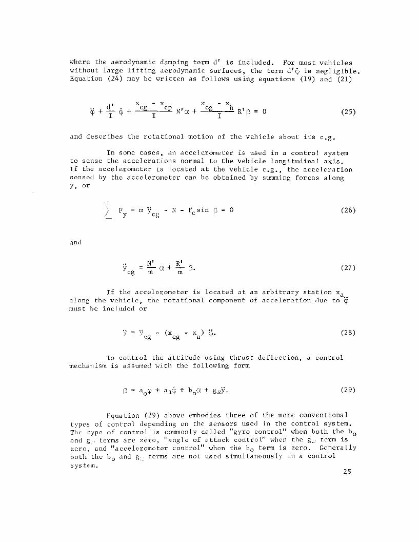
where t h e aerodynamic damping term d' i s inc luded . For most v e h i c l e s w i t h o u t l a r g e l i f t i n g aerodynamic s u r f a c e s , t h e term d l @ i s n e g l i g i b l e . Equat ion (24) may be w r i t t e n a s f o l l o w s u s i n g e q u a t i o n s (19) and (21)
and d e s c r i b e s t h e r o t a t i o n a l motion of t h e v e h i c l e abou t i t s c.g.
I n some c a s e s , an a c c e l e r o m e t e r i s used i n a c o n t r o l sys tem t o s e n s e t h e a c c e l e r a t i o n s normal t o t h e v e h i c l e l o n g i t u d i n a l a x i s . I f the a c c e l e r o m e t e r is l o c a t e d a t the v e h i c l e c.g. , the a c c e l e r a t i o n sensed by t h e a c c e l e r o m e t e r can be o b t a i n e d by summing f o r c e s a long
Y, o r
and
I f t h e a c c e l e r o m e t e r is l o c a t e d a t an a r b i t r a r y s t a t i o n x, a long t h e v e h i c l e , t h e r o t a t i o n a l component of a c c e l e r a t i o n due t o @ must be inc luded o r
To c o n t r o l t h e a t t i t u d e u s i n g t h r u s t d e f l e c t i o n , a c o n t r o l mechanism i s assumed w i t h t h e fo l lowing form
Equat ion ( 2 9 ) above embodies t h r e e of t h e more conven t iona l types of c o n t r o l depending on the s e n s o r s used i n t h e c o n t r o l system. The type of c o n t r o l i s commonly c a l l e d "gyro c o n t r o l " when b o t h t h e bo and g terms a r e z e r o , "ang le of a t t a c k c o n t r o l " when the g ~ term is z e r o , and "acce le romete r c o n t r o l " when t h e bo term is zero . G e n e r a l l y b o t h t h e bo and g L terms a r e n o t used s i m u l t a n e o u s l y i n a c o n t r o l s ys tem.
2 5
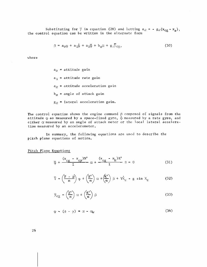
Subs t i t u t ing f o r i n equat ion (28) and l e t t i n g a 2 = - g2(xCg- xa), the con t ro l equat ion can be w r i t t e n in the a l t e r n a t e form
e.
B = aocp + slip + a,@ + boa + gzycg, (30)
where
a, = a t t i t u d e ga in
a l = a t t i t u d e r a t e ga in
a2 = a t t i t u d e a c c e l e r a t i o n gain
bo = angle of a t t a c k ga in
g2 = l a t e r a l a c c e l e r a t i o n ga in .
The con t ro l equat ion shows the engine command ? composed of s i g n a l s from the a t t i t u d e a s measured by a space-f ixed gyro, c) measured by a r a t e gyro, and e i t h e r a measured by an angle of a t t a c k meter o r the l o c a l l a t e r a l acce l e ra - t i o n measured by an accelerometer .
I n summary, the following equat ions a r e used t o desc r ibe the p i t c h plane equat ions of motion.
P i t c h Plane Equations
Y = ( ~ ) c p + ( $ ) c ! + ~ ) @ + ic - g s i n Xc

v cos Xc W . 4 = t an- I
V - V s i n X W C
The yaw plane equat ions of motion a r e obtained from the p i t c h plane equat ions by equat ing X = X c = y = 0, y = z and Y = Z.
Yaw Plane Equations
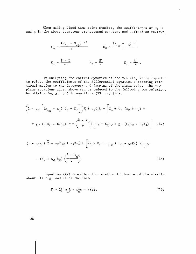
When making f i x e d t ime p o i n t s t u d i e s , t h e c o e f f i c i e n t s of a, and i n t h e above e q u a t i o n s a r e assumed c o n s t a n t and d e f i n e d a s f o l l o w s :
F - D K1 = - m
I n a n a l y z i n g t h e c o n t r o l dynamics of t h e v e h i c l e , i t i s impor tan t t o r e l a t e t h e c o e f f i c i e n t s of t h e d i f f e r e n t i a l e q u a t i o n e x p r e s s i n g r o t a - t i o n a l mot ion t o t h e f requency and damping of t h e r i g i d body. The yaw p l a n e e q u a t i o n s g i v e n above can be reduced t o t h e f o l l o w i n g two r e l a t i o n s by e l i m i n a t i n g a and i n e q u a t i o n s (39) and ( 4 0 ) .
Equa t ion ( 4 7 ) d e s c r i b e s t h e r o t a t i o n a l b e h a v i o r of t h e m i s s i l e a b o u t i t s c.g. and i s of t h e form

Comparing e q u a t i o n s (47) and ( 4 9 ) , t h e n a t u r a l f requency i s g iven
and t h e r a t i o of dampifig t o c r i t i c a l damping is
Equa t ions (50) and (513 e s t a b l i s h t h e d e s i r e d r e l a t i o n s between t h e f requency, damping and g a i n s of t h e c o n t r o l system.
To o b t a i n an e x p r e s s i o n of t h e p a t h r e a c t i o n t o t h e r o t a r y motion t h e term
from e q u a t i o n (47) is s u b s t i t u t e d i n t o e q u a t i o n (48). The r e s u l t i n g e x p r e s s i o n is ob ta ined :
- - Z = Boq3 + B1@ + B_*,
where

B. D r i f t Minimum Condi t ion [ 4 ]
It i s d e s i r a b l e t h a t the g a i n s i n t h e c o n t r o l sys tem be s e l e c t e d i n such a manner t h a t t h e l a t e r a l d r i f t a c c e l e r a t i . o n e q u a l s ze ro . Th is c o n d i t i o n is c a l l e d t h e " D r i f t Minimum P r i n c i p l e " and i s determined f o r .. . . t h e s t e a d y s t a t e c a s e ( i . e . , = @ = Z = 0 ) . R e f e r r i n g t o e q u a t i o n ( 5 2 ) , then f o r t h i s c o n d i t i o n t h e e q u a t i o n reduces t o
a, = c2 + bo + g, (K, - 2 K,).
Equat ion (55) above e s t a b l i s h e s a r e l a t i o n s h i p between the g a i n s ao , bo and g, f o r t h e d r i f t minimum c o n d i t i o n . The d r i f t minimum c o n d i t i o n can be main ta ined by us ing a n g l e of a t t a c k c o n t r o l f o r which g2 = 0 o r a c c e l e r o m e t e r c o n t r o l f o r which bo = 0. Equat ions (50) and (51) then p rov ide .two a d d i t i o n a l e q u a t i o n s f o r o b t a i n i n g the g a i n s f o r a n g l e of a t t a c k c o n t r o l o r acce le romete r c o n t r o l where t h e f requency c b and damping 5 must be s p e c i f i e d f o r t h e r i g i d body. The f requency and damping a r e s e l e c t e d based on t h e d e s i r e d t r a n s i e n t r esponse .
The d r i f t minimum c o n t r o l case d e f i n e s a c o n t r o l mode such t h a t t h e sum of t h e f o r c e components normal t o t h e nominal f l i g h t p lane i s z e r o f o r t h e s t e a d y s t a t e c o n d i t i o n only . A c l a i m f o r z e r o d r i f t can- n o t be made s i n c e i n t r a n s i e n t motion &, @ and have f i n i t e v a l u e s .
During t h e q u a s i - s t e a d y - s t a t e c o n d i t i o n t h e f i r s t and second d e r i v a t i v e s o f t h e v a r i a b l e s approach z e r o and t h e a t t i t u d e , a n g l e of a t t a c k , and eng ine d e f l e c t i o n approach l i m i t i n g v a l u e s . The q . s . s . a t t i t u d e can be found from e q u a t i o n (47) f o r 9 = tj = 0.
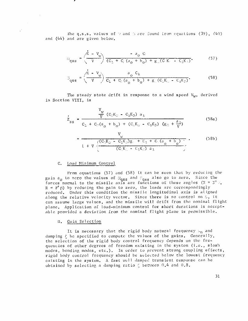
The q.s .s. v a l u e s of ( / and , a r e found from e q u a t i o n s ( 3 9 ) , (40) and (44) and a r e g iven below.
The s t e a d y s t a t e d r i f t i n r e sponse t o a wind speed V,, d e r i v e d i n S e c t i o n V I I I , is
C. Load Minimum Control
From e q u a t i o n s (57) and (58) i t can be s e e n t h a t by r e d u c i n g the g a i n a, t o z e r o the v a l u e s of ~ / q ~ ~ and 3 a l s o go t o z e r o . S ince the
q s s f o r c e s normal t o the m i s s i l e a x l s a r e f u n c t i o n s of t h e s e a n g l e s (N = N' - 1 ,
R = F I B ) by reduc ing t h e g a i n t o z e r o , t h e l o a d s a r e c o r r e s p o n d i n g l y reduced. Under t h i s c o n d i t i o n t h e m i s s i l e l o n g i t u d i n a l a x i s is a l i g n e d a l o n g t h e r e l a t i v e v e l o c i t y v e c t o r . S i n c e t h e r e is no c o n t r o l on ;, i t can assume l a r g e v a l u e s , and t h e m i s s i l e w i l l d r i f t from t h e nominal f l i g h t p lane . A p p l i c a t i o n of load-minimum c o n t r o l f o r s h o r t d u r a t i o n s is a c c e p t - a b l e provided a d e v i a t i o n from the nominal f l i g h t p lane i s p e r m i s s i b l e .
D. Gain S e l e c t i o n
I t is n e c e s s a r y t h a t the r i g i d body n a t u r a l f r equency and damping ( be s p e c i f i e d t o compute t h e v a l u e s of t h e g a i n s . G e n e r a l l y , t h e s e l e c t i o n of t h e r i g i d body c o n t r o l f requency depends on t h e f r e - quenc ies of o t h e r degrees of freedom e x i s t i n g i n the sys tem ( i . e . , s l o s h modes, bending modes, e t c . ) . I n o r d e r t o p r e v e n t s t r o n g coup l ing e f f e c t s , r i g i d body c o n t r o l f r equency should be s e l e c t e d below the lowes t f r equency e x i s t i n g i n t h e sys tem. A f a s t w e l l damped t r a n s i e n t r e sponse can be o b t a i n e d by s e l e c t i n g a damping r a t i o between 0.4 and 0 .8 .
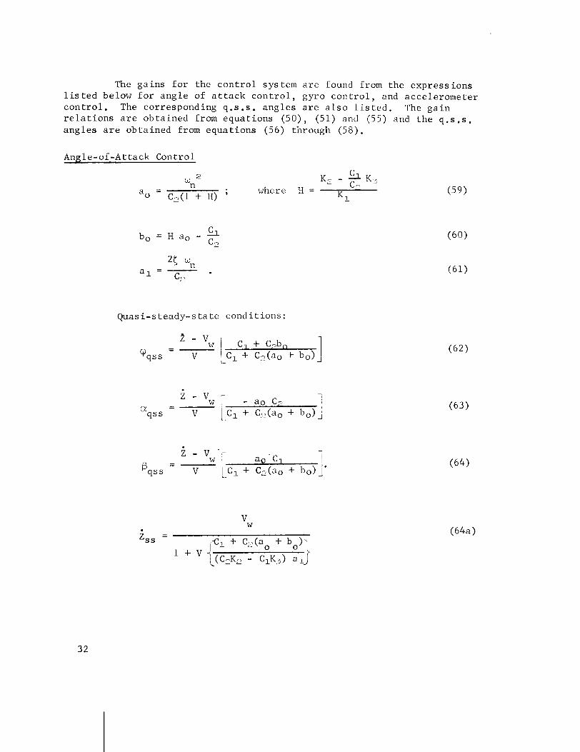
The g a i n s f o r t h e c o n t r o l sys tem a r e found from the e x p r e s s i o n s l i s t e d below f o r a n g l e of a t t a c k c o n t r o l , gyro c o n t r o l , and a c c e l e r o m e t e r c o n t r o l . The corresponding q .s .s . a n g l e s a r e a l s o l i s t e d . The g a i n r e l a t i o n s a r e o b t a i n e d from e q u a t i o n s (50) , (51) and (55) and t h e q.s . s . a n g l e s a r e o b t a i n e d from e q u a t i o n s (56) through (58) .
A n ~ l e - o f - A t t a c k Control
Quas i - s teady-s t a t e c o n d i t i o n s :
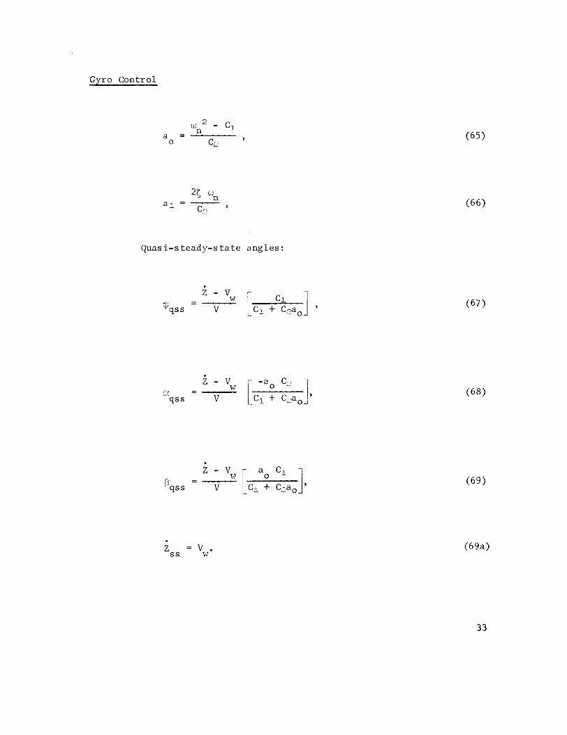
Gyro Cont ro l
Quas i-s teady-s t a t e a n g l e s :
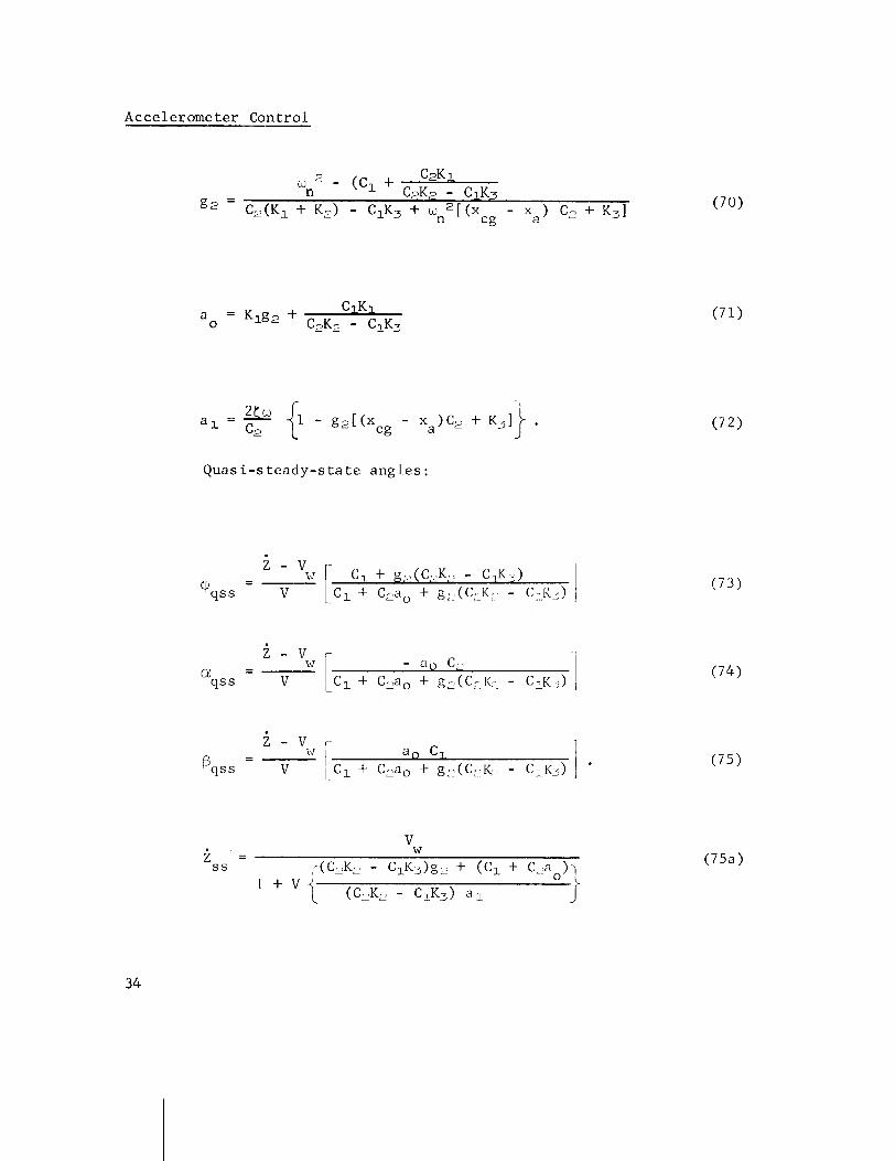
Accelerometer Cont ro l
Q u a s i - s t e a d y - s t a t e a n g l e s :
z - v i - - I a, C,
Bqs s V L C ~ + C2ao + g,?(CL'KL - CI .~3) 1
V. FLEXIBLE BODY EQUATIONS
A . Bendin2 Modes and F r e a u e n c i e s
1. Homogeneous Body
Free V i b r a t i o n s of Veh ic le
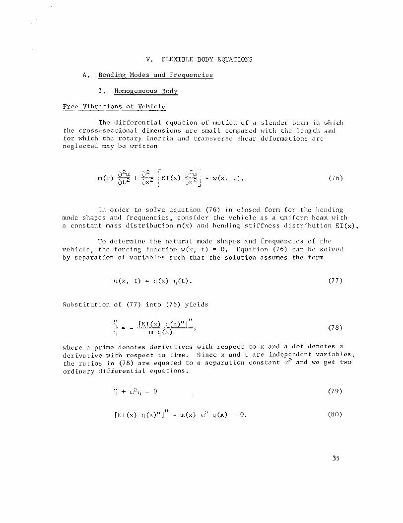
The d i f f e r e n t i a l e q u a t i o n oT mot ion of a s l e n d e r beam i n 1~~11ich t h e c r o s s - s e c t i o n a l d imensions a r e smal l compared w i t 1 1 t h e l e n g t h and f o r which t h e r o t a r y i n e r t i a and t r a n s v e r s e s h e a r de fo rmat ions a r e n e g l e c t e d may be w r i t t e n
i d2u J2 3 r U i m(x) + p 1 ) = W ( X , t ) .
L -
I n o r d e r t o s o l v e e q u a t i o n (76) i n c l o s e d form f o r the bending mode shapes and f r e q u e n c i e s , c o n s i d e r the v e h i c l e a s a uniform beam w i t h a c o n s t a n t mass d i s t r i b u t i o n m(x) and l ~ c n d i n g s t i T f n e s s d i s t r i b u t i o n EI(x) .
To de te rmine t h e n a t u r a l mode shapes and I r e q u e n c i c s of the v e h i c l e , t h e f o r c i n g f u n c t i o n w(x, t ) = 0. Equa t ion (76) can b e so lved by s e p a r a t i o n o f v a r i a b l e s such t h a t t h e s o l u t i o n assumes t h e form
S u b s t i t u t i o r i of (77) i n t o (76) y i e l d s
where a prime deno tes d e r i v a t i v e s w i t h r e s p e c t t o x and a d o t deno tes a d e r i v a t i v e w i t h r e s p e c t t o t ime. S i n c e x and t a r e independent v a r i a b l e s , t h e r a t i o s i n (78) a r e equated t o a s e p a r a t i o n c o n s t a n t w2 and we g e t two o r d i n a r y d i f f e r e n t i a 1 e q u a t i o n s .

For a c o n s t a n t s t i f f n e s s d i s t r i b u t i o n E I ( x ) and c o n s t a n t mass d i s t r i b u t i o n m(x) e q u a t i o n (80) reduces t o
where a 2 = EI/m.
The s o l u t i o n s t o e q u a t i o n s (79) and (80a) a r e , r e s p e c t i v e l y ,
TI = A s i n w t + B cos w t (81)
q (x) = C s i n h a x + D cosh x (82)
+ E s i n q m x + F cos ~76' x .
The c o n s t a n t s A and B i n (81) must be found from i n i t i a l c o n d i t i o n s i n d i sp lacement and v e l o c i t y a t t = 0 , and t h e c o n s t a n t s C , D , E , and F a r e o b t a i n e d by s p e c i f y i n g f o u r boundary c o n d i t i o n s on t h e ends of t h e beam.
The f o u r boundary c o n d i t i o n s f o r a v e h i c l e u n r e s t r a i n e d a t each end a r e o b t a i n e d from t h e c o n d i t i o n t h a t t h e s h e a r f o r c e s and bend- ing moments a t t h e nose and h inge p o i n t a r e equa l t o zero . The expres- s i o n s f o r t h e bending moment and s h e a r a t any s t a t i o n x a long t h e v e h i c l e a x i s a r e , r e s p e c t i v e l y ,
and
a p p l y i n g e q u a t i o n s (83) and (84) f o r t h e c o n d i t i o n s M = V = 0 a t t h e eng ine h i n g e p o i n t , x = 0, and nose , x = Q , t h e f o u r boundary c o n d i t i o n s become
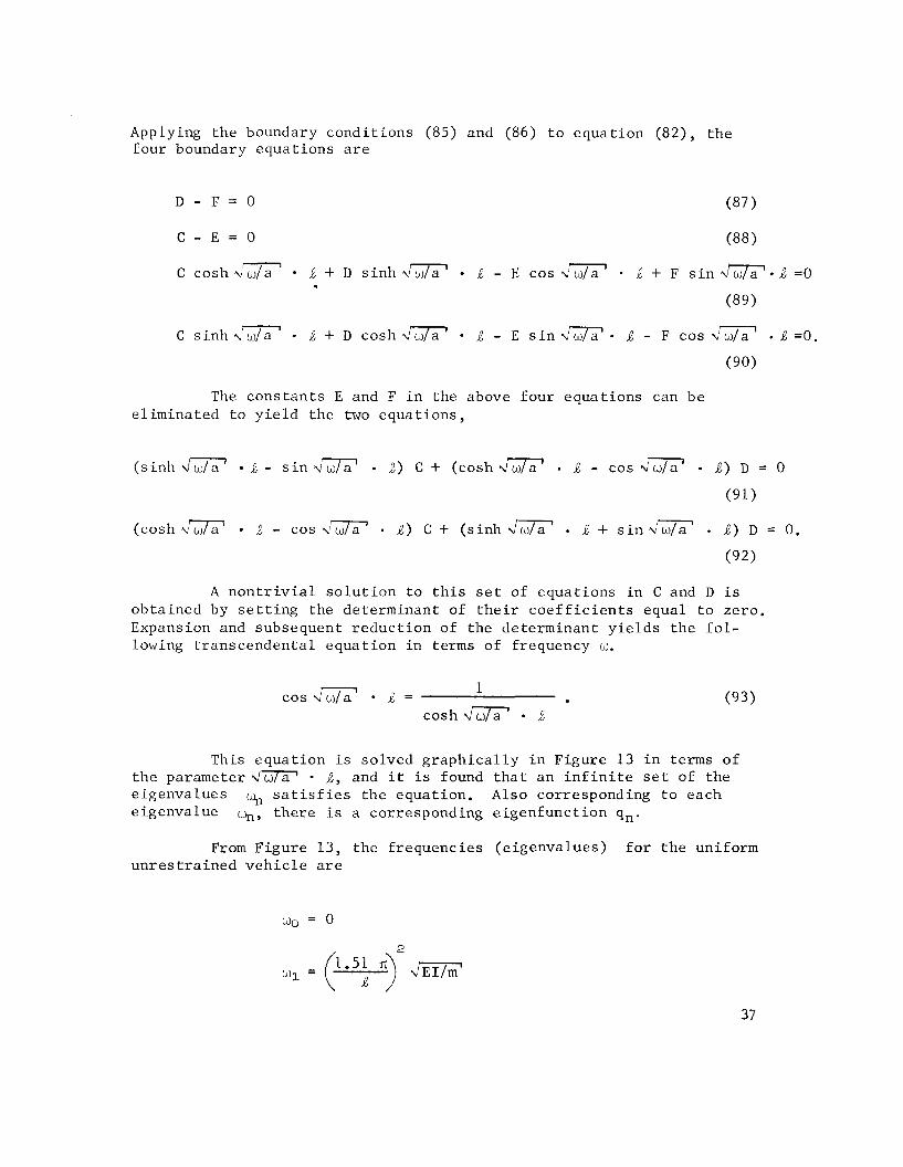
Applying the boundary condi t ions (85) and (86) t o equat ion (82), the four boundary equat ions a r e
C c o s h J m R + D s i n h J - E cos 4 w / a 1 6 + F s i n = O
(89)
C s i n h 21- + D C O S ~ w i w / a ' R - E s i n J - F cos a1 R =O.
The cons tan ts E and F i n the above four equat ions can be e l imina ted t o y i e l d the two equat ions ,
( s inh - s i n &&? Q,) C + (cosh &&? .Q - cos R) D = 0
(cosh&&? j - cos v ' m . R ) C + ( s inh &&? R + s in- J ) D = 0 .
A n o n t r i v i a l s o l u t i o n t o t h i s s e t of equat ions i n C and D i s obtained by s e t t i n g the determinant of t h e i r c o e f f i c i e n t s equal t o zero. Expansion and subsequent r educ t ion of the determinant y i e l d s the f o l - lowing t ranscendenta l equat ion in terms of frequency w.
cos rn ' .t = 1
cosh d x R
This equat ion i s solved g r a p h i c a l l y i n Figure 13 i n terms of the parameter j, and i t i s found t h a t an i n f i n i t e s e t of the eigenvalues % s a t i s f i e s the equat ion. Also corresponding t o each eigenvalue yl, t he re i s a corresponding e igenfunct ion qn.
From Figure 13, the frequencies (e igenvalues) f o r t he uniform unres t r a ined v e h i c l e a r e

FIGURE 13. GRAPHICAL SOLUTION OF TRANSCENDENTAL EQUATION FOR A UNIFORM UNRESTRATNED VEHICLE
2 2
i = ( n + i ) ($) d E 1 / m l . (n s u f f i c i e n t l y l a r g e )
The f requency oo = 0 cor responds t o t h e r i g i d body mode shape. Th i s can b e shown by s u b s t i t u t i n g wo = 0 i n e q u a t i o n (Boa), which w i l l r e d u c e i t t o
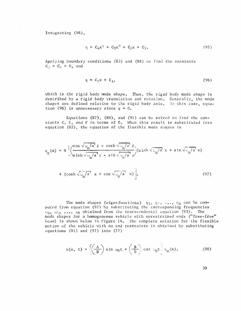
I n t e g r a t i n g (94) ,
Applying boundary c o n d i t i o n s (85) and (86) \;re f i n d t h e c o n s t a n t s C3 = Cj- = 0, and
which i s t h e r i g i d body mode shape. Thus, t h e r i g i d body mode shape i s d e s c r i b e d by a r i g i d body t r a n s l a t i o n and r o t a t i o n . G e n e r a l l y , t h e mode shapes a r e d e f i n e d r e l a t i v e t o t h e r i g i d body a x i s . In t h i s c a s e , equa- t i o n (96) is unnecessa ry s i n c e q = 0.
Equa t ions ( 8 7 ) , ( 8 8 ) , and (91) can be so lved t o f i n d t h e con- s t a n t s C, E , and F i n terms of D . When t h i s r e s u l t i s s u b s t i t u t e d i n t o e q u a t i o n ( 8 2 ) , t h e e q u a t i o n of the f l e x i b l e mode shapes i s
cos j w n / a i I - cosh /a ' k, 'I -7 ( s i n h L ~ L J / a x + s i n V'L, / a x )
n n i n h zii,, / a ' J - s i n
n n
p u t e (JJl? mode
The d from e iJ2, ...,
shapes
mode shapes ( e i g e n f u n c t i o n s ) q l , qz, . .. , qn can be com- q u a t i o n (97) by s u b s t i t u t i n g the cor respond ing f r e q u e n c i e s
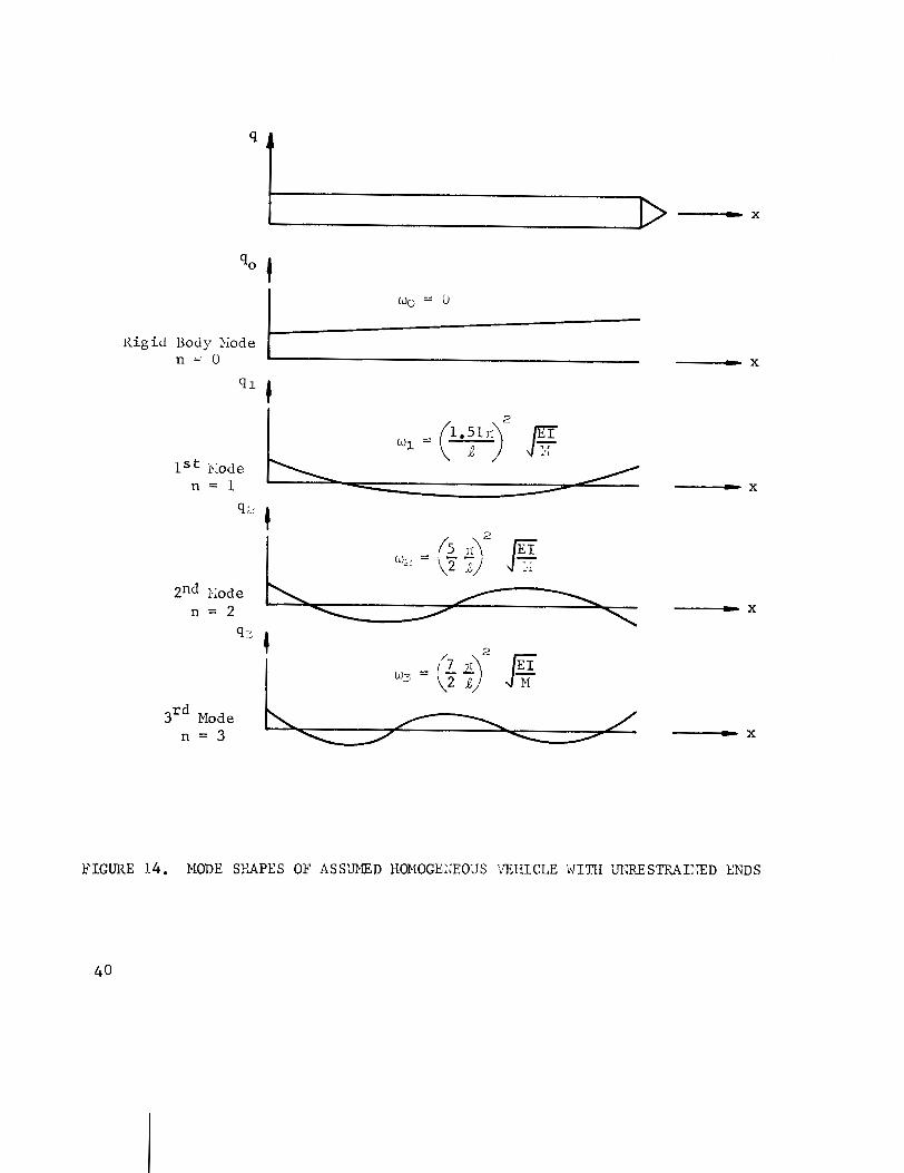
o b t a i n e d from t h e transcendental e q u a t i o n (93) . The for a homogeneous v e h i c l e w i t h u n r e s t r a i n e d ends ( " f r e e - f r e e "
beam) i s shown below i n F i g u r e 14. The complete s o l u t i o n f o r t h e f l e x i b l e mot ion of t h e v e h i c l e w i t h no end r e s t r a i n t s i s o b t a i n e d by s u b s t i t u t i n g e q u a t i o n s (81) and (97) i n t o (77)
B ( x , t ) = [(+I s i n q,t + j-'I cos .+,tI q n ( x ) .
\ D , 1
3rd Mode n = 3
K i g i d Body Piode
FIGURE 14. NODE SFAPES OF AS S'JMED H0MOGE:;EUdS 'bTIIICLE WITH 'fi?RE S ~ ~ I I ~ D ENDS
wo = 0
n = O X
Since equat ion (98) i s a s o l u t i o n f o r any va lue n, the sum of the s o l u t i o n s i s a l s o a so lu t ion .
u(x , t ) = ) A : s i n w t + B' cos L. I n n n= 1
Forced Motion of F l e x i b l e Vehicle
I n t he previous s e c t i o n , t he motion of the s imp l i f i ed v e h i c l e has been found f o r the case of f r e e v i b r a t i o n s i n which no e x t e r n a l forc ing func t ion w(x, t ) was a c t i n g on the veh ic l e . For t he case of forced motion, the mode shapes obtained previous ly f o r t he f r e e v ib ra - t i o n case a r e normalized by the d e f l e c t i o n qn taken g e n e r a l l y a t the engine hinge point . I n t h i s case the mode shapes de f ine only the r e l a t i v e displacements and w i l l be denoted by y i ( x ) .
The displacement due t o the load w(x, t ) can be expanded i n a s e r i e s of e igenfunct ions such t h a t
where yi(x) a r e the normalized n a t u r a l mode shapes and .rli(t) a r e the normal displacement coord ina tes . Subs t i t u t ing equat ion (100) i n t o the beam equat ion given by equat ion (76) y i e l d s
The func t ion w(x, t ) denotes the forc ing func t ion a c t i n g normal t o the r i g i d body center l i n e and a r i s e s from engine fo rces , aerodynamic f o r c e s , p rope l l an t s losh ing fo rces , e t c .
Equa t ion 101 can be reduced t o a s imple form by u s i n g t h e con- d i t i o n s of o r t h o g o n a l i t y between t h e e i g e n f u n c t i o n s o r mode shapes . The c o n d i t i o n of o r t h o g o n a l i t y is g i v e n by
where t h e e i g e n f u n c t i o n s yi(x) and y j ( x ) a r e o r thogona l t o each o t h e r w i t h r e s p e c t t o t h e we igh t ing f u n c t i o n m(x).
M u l t i p l y i n g e q u a t i o n (80) and (101) through by y . and i n t e g r a t - J
ing b o t h s i d e s w i t h r e s p e c t t o x g i v e s t h e fo l lowing two e q u a t i o n s ,
CO 1
R
) :i 1 yi y j m dx + 7 T i f ( E I Y;)" y. dx = w(x, t ) yj dx .-I 1-. J 3 ci
n= 1 o n= 1 o o (104)
J f m yi y. dx. r (EI y'!)" y . dx = wi
L J
Replacing t h e second term of e q u a t i o n (104) by e q u a t i o n (105) g i v e s
which reduces t o the f o l l o w i n g , us ing e q u a t i o n (102)
The q u a n t i t i e s on the r i g h t hand s i d e of (107) a r e
M . = my? dx (genera l ized mass) J
0
I Q j = J W(X, t ) Y j dx. (genera l ized fo rce )
Equation (107) g ives the response of the j t h mode t o the forc ing func t ion Qj. I f w(x, t ) i s independent of the motion of the beam, the modes a r e uncoupled and can be solved sepa ra t e ly . I n the a c t u a l case the aerodynamic fo rces , t h r u s t forces and s losh ing fo rces a r e coupled wi th the f l e x i b l e motion of the veh ic l e .
I n p r a c t i c a l a p p l i c a t i o n s each of the bending modes possess some d i s s i p a t i v e forces which provide damping. This d i s s i p a t i v e energy i s small i n comparison t o the e l a s t i c and k i n e t i c energ ies and i t s e f f e c t can be approximated by including a viscous damping term i n equat ion (107).
The damping r a t i o may vary between .0002 I ( i .025.
To i l l u s t r a t e the response of the f l e x i b l e mode t o a fo rc ing func t ion assume t h a t the forc ing func t ion i s aerodynamic loading and i s uniformly d i s t r i b u t e d over the length of the veh ic l e . The aerodynamic loading w i l l be given by w(x, t ) = w(x) s i n a, where a i s the angle of a t t a c k . I f we l e t the angle of a t t a c k vary wi th the con t ro l frequency w, such t h a t a = w c t , the genera l ized force w i l l be
Qi = s i n o,,t W(X) yi(x) dx.
0
Then,
- - 0 " 71 + 2Ci ui ;li + w: 1 1 ~ s i n c t .
El
The t r a n s i e n t s o l u t i o n o f e q u a t i o n ( 1 1 2 ) i s 011tciinc.d b y s e t t i n g Q ~ / M ~ = 0 and i s
- ( W i t
i l i = Aie s i n (L d t - 1 L . )
where w d i s t h e damped n a t u r a l f r e q u e n c y ,
The p a r t i c u l a r o r s t e a d y - s t a t e s o l u t i o n of e q u a t i o n (112) i s
' l i = B . s i n (w t - 1, 1 C
where t h e a m p l i t u d e i s
and t h e phase l a g i s
The complete s o l u t i o n o f e q u a t i o n (112) c o n s i s t s of t h e sum of t h e t r a n s i e n t and s t e a d y - s t a t e s o l u t i o n s g i v e n by e q u a t i o n s (113) and (115) , r e s p e c t i v e l y .
Trio i n i t i a l c o n d i t i o n s a r e r e q u i r e d t o de te rmine t h e c o n s t a n t s Ai and I$ i n e q u a t i o n (118) , and can be found by s p e c i f y i n g t h a t t h e i n i t i a l d i sp lacement and v e l o c i t y a r e z e r o ; u ( x , 0 ) = G(x, 0) = 0 a t t = 0. The cor respond ing normal d i s p l a c e m e n t and v e l o c i t y ~ l ( 0 ) and i ( 0 ) must a l s o be z e r o a s can be v e r i f i e d by s u b s t i t u t i n g t h e s e i n i t i a l condi- t i o n s i n e q u a t i o n (100) . The c o n s t a n t s i n e q u a t i o n (113) s u b j e c t t o t h e i n i t i a l c o n d i t i o n s ~ ( 0 ) = ?,(0) = 0 become
and
The r e s u l t i n g mot ion of t h e e l a s t i c d i sp lacement r e l a t i v e t o t h e l o n g i - t u d i n a l r i g i d body a x i s due t o t h e d i s t r i b u t e d aerodynamic l o a d i n g i s then
00 - t w i t
U(X, t ) = 1 y i ( x ) (A? 1 s i n (w d t . - qi ) + Bi s i n (w c t - Q)) . (121)
n= l
The t r a n s i e n t term i n e q u a t i o n (121) becomes n e g l i g i b l y smal l a s t ime becomes l a r g e due t o t h e e x p o n e n t i a l te rm e-cut . The second term remains s i n u s o i d a l w i t h i t s ampl i tude and phase a n g l e dependent on c i and wc/wi . The f a m i l i a r r e sonance c o n d i t i o n o c c u r s a s t h e con- t r o l f r equency wc approaches one o f t h e bending mode f r e q u e n c i e s wi.
2. Nonhomogeneous Body
Space veh ic le . conf igura r i o n s a r e s u f f i c i e n t l y complex i n t h e i r s t r u c t u r a l makeup t h a t a lumped parameter i d e a l i z a t i o n of t h e sys tem i s o f t e n used i n computing t h e mode shapes of t h e v e h i c l e . The b a s i c d a t a r e q u i r e d f o r t h e c a l c u l a t i o n of t h e n a t u r a l mode c o n s i s t of (1) t h e d i s t r i b u t e d mass m(x) and r o t a r y i n e r t i a p.(x), and (2) t h e bending s t i f f n e s s E I ( x ) and s h e a r s t i f f n e s s KG(x) d i s t r i b u t i o n .
For a t y p i c a l s p a c e v e h i c l e , a s e t of cu rves r e p r e s e n t i n g t h e s t r u c t u r a l and i n e r t i a l p r o p e r t i e s a r e shown i n F igure 15. Here t h e curves of y (x ) and KG(x) a r e n o t shown, b u t a r e of t h e same g e n e r a l form. I n t h e d i s c u s s i o n t h a t f o l l o w s , t h e r o t a r y i n e r t i a p(x) and KG(x) w i l l b e n e g l e c t e d . It h a s been shown [ I ] t h a t t h e r o t a r y i n e r t i a can b e n e g l e c t e d w i t h o u t a p p r e c i a b l e e r r o r i n mode shapes b u t t h e e f f e c t s of s h e a r f l e x i b i l i t y KG(x) should be inc luded .
I n beam t h e o r y , t h e t o t a l l i n e a r o r a n g u l a r d e f l e c t i o n of any p o i n t can be r e p r e s e n t e d a s the sum of t h e d e f l e c t i o n s a t t h a t p o i n t pro- duced by i n d i v i d u a l f o r c e s and moments. This i s a s t a t e m e n t of t h e p r i n c i p l e of s u p e r p o s i t i o n f o r l i n e a r systems and i s expressed rnathe- m a t i c a l l y a s
where F j i s a n a r b i t r a r y f o r c e o r moment c a l l e d a " g e n e r a l i z e d fo rce" and q i r e p r e s e n t s t h e l i n e a r o r a n g u l a r d i sp lacement and i s c a l l e d a " g e n e r a l i z e d c o o r d i n a t e . I 1 The c o n s t a n t s C i j a r e c a l l e d the f l e x i b i l i t y i n f luence c o e f f i c i e n t s .
I f we l e t F. r e p r e s e n t f o r c e s and qi r e p r e s e n t l i n e a r d i s p l a c e - 3
ment, then Ci j r e p r e s e n t s the d e f l e c t i o n a t s t a t i o n i due t o a u n i t l o a d a t s t a t i o n j. Using DIAlember t ' s p r i n c i p l e , l e t t h e f o r c e s F j r e p r e s e n t t h e a p p r o p r i a t e i n e r t i a f o r c e s ; t h e n ,

V e h i c l e S t a t i o n
(b
BENDING STIFFNESS
FIGURE 15 . TYPICAL MASS AND B E N D I K G STIFFNESS DISTRIBUTION
I f we c o n s i d e r harmonic o s c i l l a t i o n s of t h e system, t h e p a r t i c u - l a r s o l u t i o n s of t h e sys tem a r e of t h e form
- i u t q j - q j e
i w t P j = i~ q . e J
.. - - - i w t
j u2 q j e
j u t F = m b j 2 q j e . j j
Now s u b s t i t u t i n g e q u a t i o n s (127) and (124) i n t o (1 22) and d i v i d i n g through by w2ei"t, we g e t
When w r i t t e n i n m a t r i x form, e q u a t i o n s (128) become
S ince t h e r e l a t i v e magnitudes of t h e d i sp lacements ql, q;i . . . qn a r e s u f f i c i e n t t o d e f i n e t h e shape o f t h e mode o f v i b r a t i o n , i t i s con- v e n i e n t t o normal ize e q u a t i o n (129) by t h e d e f l e c t i o n qn taken g e n e r a l l y a t t h e eng ine h inge p o i n t . The r e s u l t i n g q u a n t i t i e s w i l l b e r e f e r r e d t o a s components of normalized e i g e n v e c t o r , d e f i n e d by t h e e x p r e s s i o n s
A f t e r n o r m a l i z i n g then w i t h r e s p e c t t o qn, e q u a t i o n s (129) become
W r i t t e n i n t h i s m a t r i x form, e q u a t i o n (131) r e p r e s e n t s a s e t of n s imul taneous e q u a t i o n s of motion and can b e s o l v e d by m a t r i x i t e r a t i o n f o r t h e n a t u r a l f r equency L, of the f i r s t mode of v i b r a t i o n and t h e cor - r e spond ing normal ized ampl i tudes y l , y,, . . . , yn = 1, which d e f i n e t h e shape of t h e e l a s t i c d e f l e c t i o n curve .
The s q u a r e m a t r i x on the r i g h t s i d e of e q u a t i o n (131) i s t h e dynamic m a t r i x and is s e e n t o c o n s i s t of t h e p roduc t of t h e e l a s t i c m a t r i x and i n e r t i a m a t r i x , o r
To compute t h e shapes and f r e q u e n c i e s of h i g h e r modes than t h e f i r s t mode, i t i s n e c e s s a r y t o s u p p r e s s the dominant tendency of t h e e q u a t i o n s of mot ion t o converge t o t h e shape and f requency of the f i r s t mode d u r i n g t h e i t e r a t i o n p r o c e s s . Th i s can be e f f e c t i v e l y accomplished by i n t r o d u c i n g t h e o r t h o g o n a l i t y r e l a t i o n s h i p between p r i n c i p a l modes of v i b r a t i o n , i. e . ,
where yj and y j S a r e t h e normal ized ampl i tude of t h e r and s mode, r e s p e c t i v e l y , r # s. The o r t h o g o n a l i t y c o n d i t i o n , e q u a t i o n (133) , can b e w r i t t e n i n a s l i g h t l y modi f i ed form by m u l t i p l y i n g i t by the r a t i o cinIYnr shown below t o e l i m i n a t e , s a X t h e n t h degree of freedom and y i e l d s t h e n e q u a t i o n s ,
The above e x p r e s s i o n can be w r i t t e n a s fo l lows and r e p r e s e n t s the modif ied form of t h e o r t h o g o n a l i t y c o n d i t i o n .
Wr i t ing t h e expanded form of e q u a t i o n (131) t o d e f i n e the shape and f requency of t h e s f l e x u r a l mode, we have
By s u b t r a c t i n g t h e f i r s t e q u a t i o n of (135) from t h e f i r s t e q u a t i o n o f (136) t h e second e q u a t i o n of (135) from the second equa- t i o n of (136) e t c . , ynS can be e l i m i n a t e d from a11 b u t t h e n t h e q u a t i o n and the o r t h o g o n a l i t y r e l a t i o n s h i p in t roduced . Per iorming t h e s e o p e r a t i o n s ,
where k = n - 1.
Excluding t h e n t h e q u a t i o n of (137) , t h e r e a r e (n-1) e q u a t i o n s i n t h e (n-1) parameters ylS, y2S, . . . , yn-lS. A s o l u t i o n t o t h i s s e t o f e q u a t i o n s i s a l s o a s o l u t i o n t o t h e o r i g i n a l n e q u a t i o n s .
P u t t i n g e q u a t i o n (137) i n m a t r i x form y i e l d s
where k = n - 1 and ykS = 1.
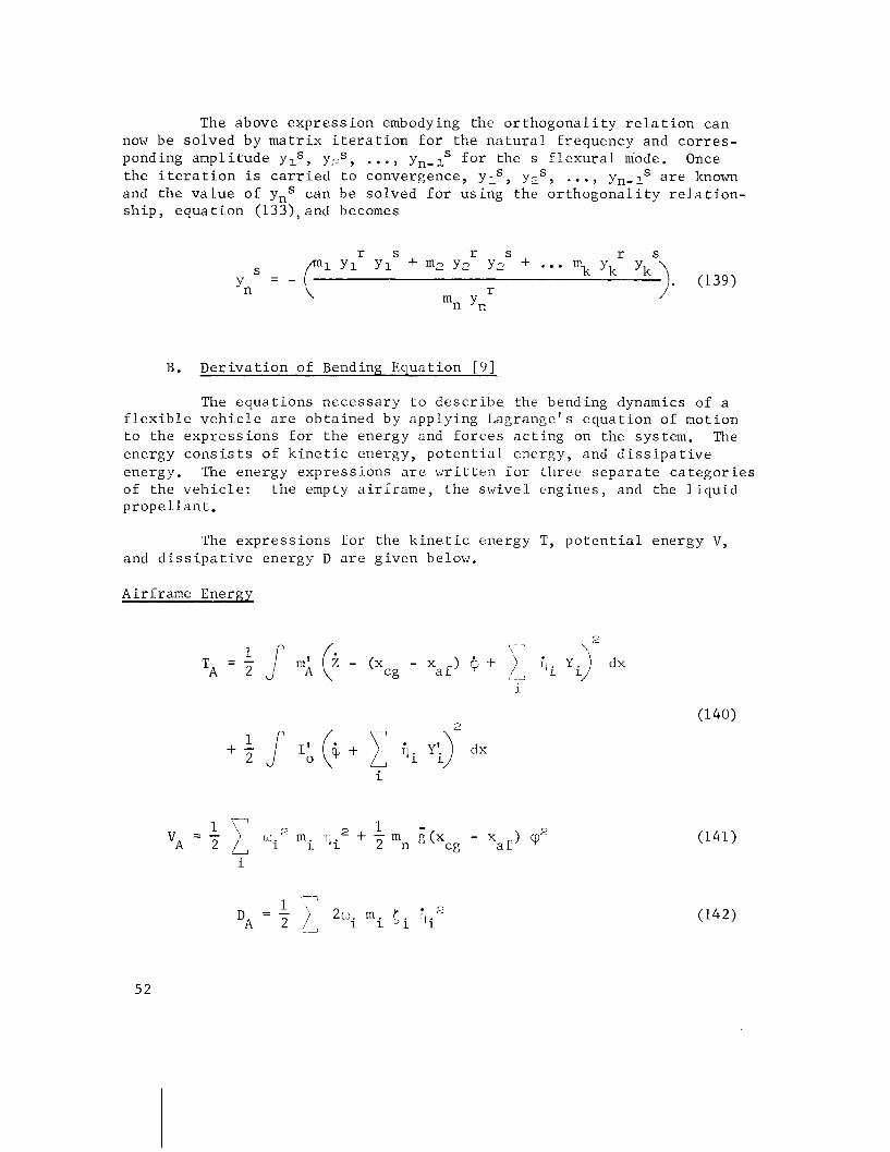
The above e x p r e s s i o n embodying the o r t h o g o n a l i t y r e l a t i o n can now be s o l v e d by m a t r i x i t e r a t i o n f o r t h e n a t u r a l f requency and c o r r e s - ponding amp1 i t u d e yls, yZs, . . . , yn- lS f o r the s f l e x u r a l mode. Once t h e i t e r a t i o n i s c a r r i e d t o convergence, ylS, yZS, ..., yn-lS a r e known and t h e v a l u e o f ynS can be s o l v e d f o r u s i n g the o r t h o g o n a l i t y r e l a t i o n - s h i p , e q u a t i o n (133), and becomes
B. D e r i v a t i o n of Bending Equa t ion [ 9 ]
The e q u a t i o n s n e c e s s a r y t o d e s c r i b e t h e bending dynamics of a f l e x i b l e v e h i c l e a r e o b t a i n e d b y app ly ing Lagrange 's e q u a t i o n of mot ion t o t h e e x p r e s s i o n s f o r t h e energy and f o r c e s a c t i n g on the system. The energy c o n s i s t s of k i n e t i c energy, p o t e n t i a l energy, and d i s s i p a t i v e energy. The energy e x p r e s s ions a r e w r i t t e n f o r t h r e e s e p a r a t e c a t e g o r i e s of t h e v e h i c l e : t h e empty a i r f r a m e , t h e s w i v e l e n g i n e s , and t h e l i q u i d p r o p e l l a n t .
The e x p r e s s i o n s f o r t h e k i n e t i c energy T, p o t e n t i a l ene rgy V , and d i s s i p a t i v e energy D a r e g i v e n below.
Airf rame Energy
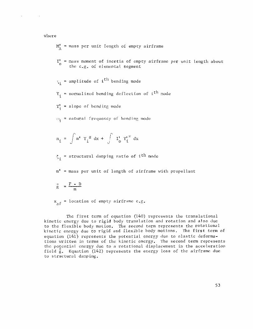
M;i = mass p e r u n i t l e n g t h of empty a i r f r a m e
I' = mass moment of i n e r t i a of empty a i r f r a m e p e r u n i t l e n g t h a b o u t 0
t h e c.g. of e l e m e n t a l segment
r i i = a m p l i t u d e of it" bending mode
'i = normal ized bending d e f l e c t i o n of ith mode
Y i = s l o p e of bending mode
w = n a t u r a l f r equency o i bending mode i
( . = s t r u c t u r a l damping r a t i o of ith mode 1
m' = mass p e r u n i t of l e n g t h of a i r f r a m e w i t h p r o p e l l a n t
- F - D g = - m
x = l o c a t i o n of empty a i r f r a m e c.g. a f
The f i r s t term of e q u a t i o n (140) r e p r e s e n t s t h e t r a n s l a t i o n a l k i n e t i c ene rgy due t o r i g i d body t r a n s l a t i o n and r o t a t i o n and a l s o due t o t h e f l e x i b l e body motion. The second term r e p r e s e n t s t h e r o t a t i o n a l k i n e t i c energy due t o r i g i d and f l e x i b l e body mot ions . The f i r s t term of e q u a t i o n (141) r e p r e s e n t s t h e p o t e n t i a l energy due t o e l a s t i c deforma- t i o n s m i t t e n i n terms of t h e k i n e t i c energy. The second term r e p r e s e n t s t h e p o t e n t i a l energy due t o a r o t a t i o n a l d i sp lacement i n t h e a c c e l e r a t i o n f i e l d g. Equa t ion (142) r e p r e s e n t s t h e energy l o s s of t h e a i r f r a m e due t o s t r u c t u r a l damping.
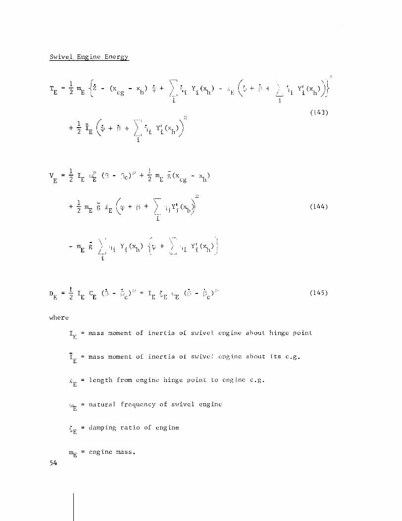
Swivel Engine Energy
where
IE = mass moment of i n e r t i a of swive l eng ine abou t h inge p o i n t
IE - = mass moment of i n e r t i a of swive l eng ine abou t i t s c .g .
6~ = l e n g t h from eng ine h inge p o i n t t o engine c .g .
b b = n a t u r a l f requency of swive l eng ine
CE = damping r a t i o of eng ine
mE = eng ine mass.
54
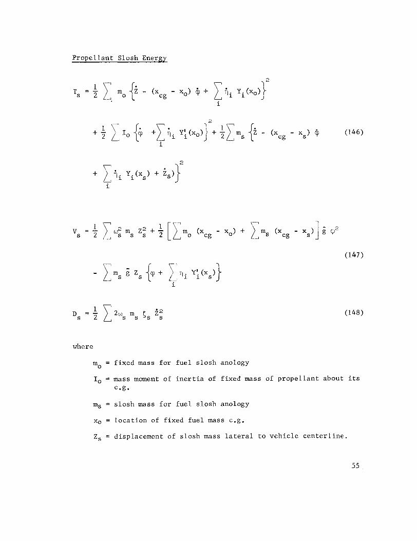
Propellant Slosh Energy
where
mo = fixed mass for fuel slosh anology
I, = mass moment of inertia of fixed mass of propellant about its c . g .
ms = slosh mass for fuel slosh anology
xo = location of fixed fuel mass c.g.
Zs = displacement of slosh mass lateral to vehicle centerline.
Xs = l o c a t i o n of s lo sh ing mass c.g.
as = n a t u r a l frequency of o s c i l l a t i n g p rope l l an t
C s = damping r a t i o of p rope l l an t .
I n order t o use Lagrange' s equa t ion , t he fol lowing d e r i v a t i v e s a r e necessary.
3DE - = 0 a t i
where SE = mE RE.
Using t h e above d e r i v a t i v e s and t h e Lagrange e q u a t i o n , t h e bending e q u a t i o n becomes
E q u ~ t i o n (161) can be s i m p l i f i e d by n o t i n g t h a t t h e coef - f i c i e n t s of Z and $ r e p r e s e n t mass and i n e r t i a terms t a k e n abou t t h e v e h i c l e c.g. S i n c e t h e l i n e a r and a n g u l a r momentum i s conserved f o r t h e normal modes of v i b r a t i o n , then
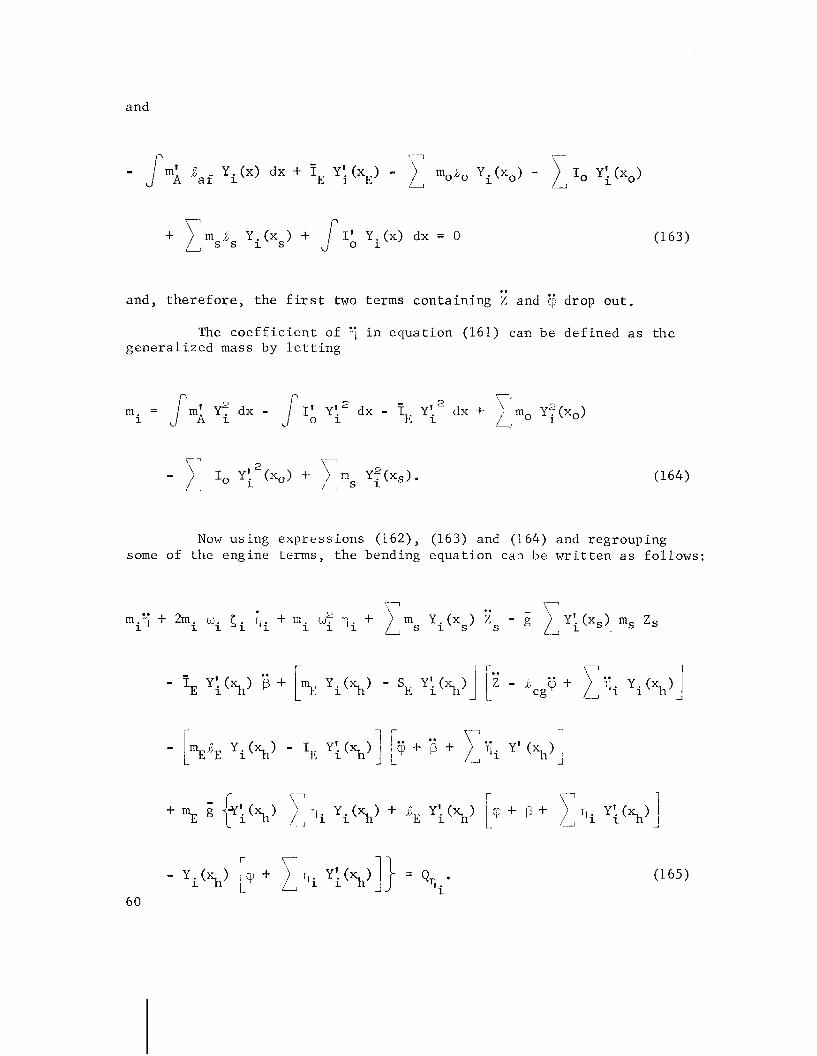
. . and, t h e r e f o r e , t h e f i r s t two terms c o n t a i n i n g Z and @ drop out .
The c o e f f i c i e n t of ij i n equat i -on (161) can be d e f i n e d a s t h e g e n e r a l i z e d mass by l e t t i n g
Now u s i n g e x p r e s s i o n s (162), (163) and (164) and regroup ing some of t h e engine terms, t h e bending e q u a t i o n can be w r i t t e n a s fo l lows :
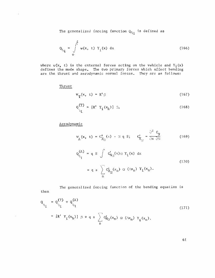
The g e n e r a l i z e d f o r c i n g f u n c t i o n QTli i s d e f i n e d a s
where w ( x , t ) i s t h e e x t e r n a l f o r c e s a c t i n g on t h e v e h i c l e and Yi(x) d e f i n e s t h e mode shape. The two pr imary f o r c e s which a f f e c t bending a r e t h e t h r u s t and aerodynamic normal f o r c e s . They a r e a s fo l lows :
T h r u s t
Aerodynamic
The g e n e r a l i z e d f o r c i n g f u n c t i o n of t h e bending e q u a t i o n i s then

The bending e q u a t i o n can now be w r i t t e n a s
where
Equat ion (172) above d e s c r i b e s the bending dynamics of the f l e x i b l e v e h i c l e f o r each i t h mode of v i b r a t i o n . Equat ion (173) r e p r e s e n t s t h e
6 2
f o r c i n g f u n c t i o n due t o k p r o p e l l a n t s l o s h modes, engine dynamics and .. aer.odynamic f o r c e s . F r e q u e n t l y , t h e q j , T . , Z , @ and rp terms a r e s m a l l i n comparison t o the o t h e r terms i n e q u a t i d n (173) and a r e n e g l e c t e d .
The open- loop coup1 ing be tween each o r thogona l bending mode (T, t o .) can occur through t h e fo l lowing f o r c e s : (1) aerodynamic damping, (2) eng ine t h r u s t and eng ine i n e r t i a , and (3) eng ine girnba 1 b e a r i n g f r i c t i o n . Some of t h e s e e f f e c t s have been n e g l e c t e d i n t h e f o r c i n g f u n c t i o n of e q u a t i o n (17 3) .
The open-loop coupl ings between t h e nonor thogonal modes i n equa- t i o n (173) a r e
(1) q i t o mode Z s , coupled i n e r t i a l l y and e l a s t i c a l l y ,
(2) v i t o mode p, coupled i n e r t i a l l y and through t h r u s t f o r c e s ,
(3 ) rli t o mode a, coupled through aerodynamic f o r c e s .
The c losed loop coup l ing of 7 t o mode 7. depends on t h e t r a n s - m i t t a n c e from mode t o c o n t r o l s y s tem, f . e . , t h e way i n which t h e mode is sensed by t h e c o n t r o l system.
V I . SLOSH EQUATIONS [ 9 ]
The motion of l i q u i d p r o p e l l a n t s i n c y l i n d r i c a l t anks can be d e s c r i b e d by t h e w e l l known spring-mass model. This method g i v e s t h e e n g i n e e r an i n s i g h t i n t o t h e problem and lends i t s e l f t o a d e s c r i p t i o n of t h e l i q u i d motion which is r e a d i l y adap ted f o r d i g i t a l and ana log s i m u l a t i o n .
This mechanical ana log d u p l i c a t e s t h e hydrodynamic f o r c e s and moments a c t i n g on t h e t a n k which a r e s imula ted by r e p l a c i n g t h e s l o s h mass by a n e q u i v a l e n t r i g i d mass f o r each fundamental s l o s h mode. Reference 2 con- t a i n s t h e necessa ry g raphs t o determine t h e s l o s h mass, s l o s h mass l o c a - t i o n , a s s o c i a t e d s p r i n g c o n s t a n t and damping c o n s t a n t , and o t h e r s l o s h v a r i a b l e s v e r s u s t h e l i q u i d column he igh t - to - tank-d iamete r r a t i o f o r t anks w i t h c i r c u l a r and a n n u l a r c r o s s s e c t i o n s .
The b a l a n c e of t h e p r o p e l l a n t e x c l u s i v e of t h e s l o s h mass is assumed r i g i d and is included i n the t o t a l mass and mass moment of i n e r t i a of t h e v e h i c l e .
The pendulum ana logy used t o d u p l i c a t e t h e mot ion o f t h e s l o s h i n g p r o p e l l a n t s is s i m i l a r t o t h e spr ing-mass model. I n t h i s c a s e , t h e s l o s h mass is rep laced w i t h a r i g i d mass suspended by a m a s s l e s s l i n k i n l e n g t h ,l a s shown below.
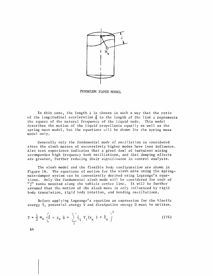
PENDULUM SLOSH MODEL
I n t h i s c a s e , t h e l e n g t h .J? i s chosen i n such a way t h a t t h e r a t i o of t h e l o n g i t u d i n a l a c c e l e r a t i o n g t o t h e l e n g t h of t h e l i n k J r e p r e s e n t s t h e s q u a r e of t h e n a t u r a l f requency of t h e l i q u i d mode. Th is model d e s c r i b e s t h e motion of t h e l i q u i d p r o p e l l a n t s e q u a l l y a s w e l l a s t h e s p r i n g mass model, b u t t h e e q u a t i o n s w i l l be shown f o r t h e s p r i n g mass model on ly .
G e n e r a l l y on ly t h e fundamental mode o f o s c i l l a t i o n is cons idered s i n c e t h e s l o s h masses of s u c c e s s i v e l y h i g h e r modes have l e s s i n f l u e n c e . Also t e s t exper ience i n d i c a t e s t h a t a g r e a t d e a l of t u r b u l e n t mixing accompanies h i g h f requency tank o s c i l l a t i o n s , and t h a t damping e f f e c t s a r e g r e a t e r , f u r t h e r reduc ing t h e i r s i g n i f i c a n c e i n c o n t r o l a n a l y s i s .
The s l o s h model and t h e f l e x i b l e body c o n f i g u r a t i o n a r e shown i n F i g u r e 16. The e q u a t i o n s of motion f o r t h e s l o s h mass u s i n g t h e s p r i n g - mass-damper sys tem can be c o n v e n i e n t l y d e r i v e d u s i n g Lagrange 's equa- t i o n s . Only t h e fundamental s l o s h mode w i l l b e cons idered f o r each of "j" tanks mounted a long t h e v e h i c l e c e n t e r l i n e . It w i l l be f u r t h e r assumed t h a t t h e motion of t h e s l o s h mass i s on ly i n f l u e n c e d by r i g i d body t r a n s l a t i o n , r i g i d body r o t a t i o n , and bending o s c i l l a t i o n s .
Before a p p l y i n g Lagrange 's e q u a t i o n an e x p r e s s i o n f o r t h e k i n e t i c energy T, p o t e n t i a l energy V and d i s s i p a t i v e energy D must be w r i t t e n .

FIGURE 16. SPRING MASS DAMPER SLOSH MODEL
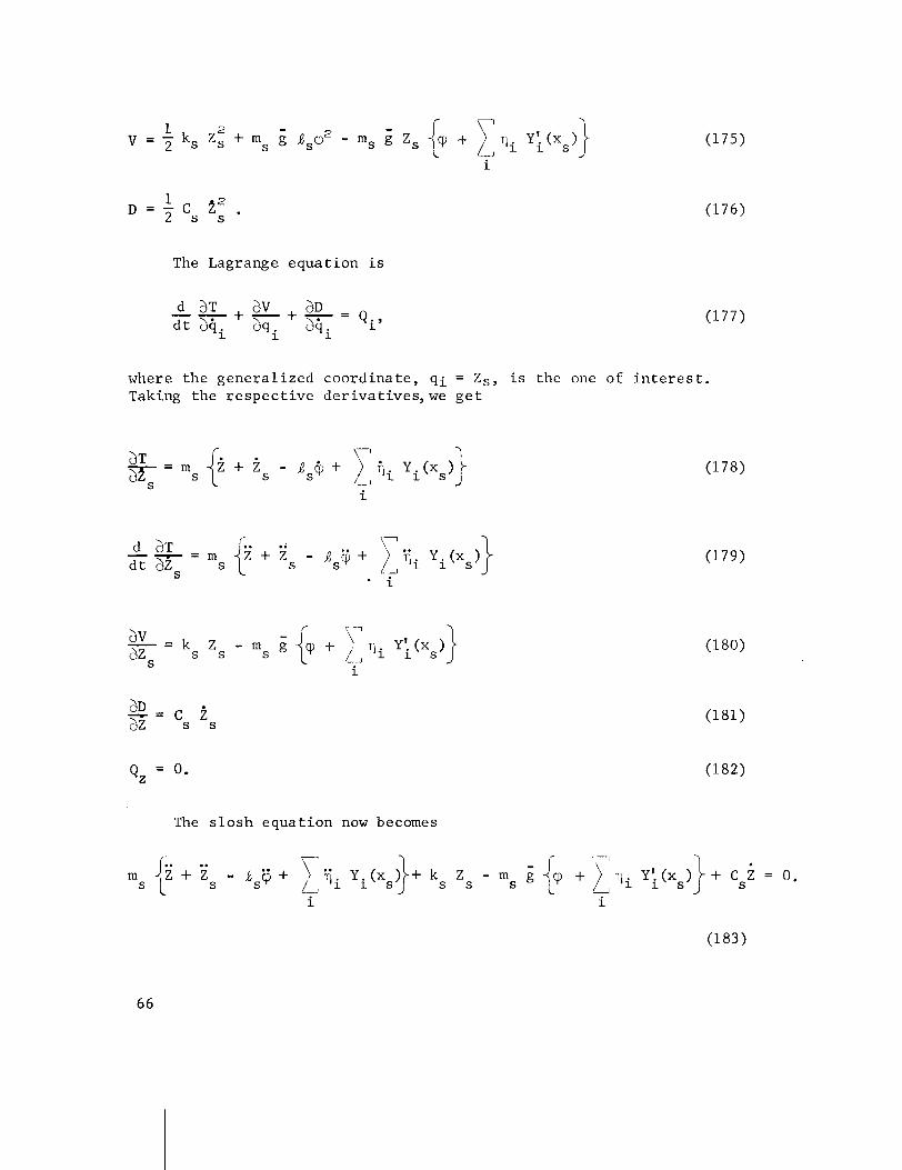
The Lagrange equat ion is
where the genera l ized coord ina te , q i = Zs , i s the one of i n t e r e s t . Taking the r e spec t ive der iva t ives , we g e t
The s l o s h equat ion now becomes
Since 25, us = cS/ms and wg = ks/ms, the ' s losh equat ion becomes
The r ight-hand s i d e of equat ion (184) r e p r e s e n t s the forc ing func t ion of the s lo sh ing mode. The p rope l l an t s losh ing modes a r e forced only by i n e r t i a l coupling wi th t h e v e h i c l e r i g i d and e l a s t i c body modes. The coupling of the s losh ing modes back i n t o t h e v e h i c l e i s a combination of both i n e r t i a l and e l a s t i c coupling.
I f t he f l i g h t con t ro l system d i r e c t l y senses p rope l l an t motions, then i t responds t o these s i g n a l s and r e a c t s on the body modes; these i n t u rn a f f e c t the p rope l l an t modes. I f the f l i g h t con t ro l system does n o t sense p rope l l an t motion d i r e c t l y ( t h e more common case ) , then i t sees these motions only a s the body modes (which i s the case with con- ven t iona l sensors ) . In e i t h e r case, t he s l o s h modes must have t h e i r loops " f i l t e r e d " by the body modes. It fol lows then t h a t these pro- p e l l a n t modes w i l l only couple s i g n i f i c a n t l y wi th modes in t h e i r immediate frequency range o r w i th modes having a l a r g e enough pass band t o encompass t he s l o s h frequencies .
V I I . WIND REPRESENTATION
The fol lowing i s a b r i e f o u t l i n e of t he method t o be used i n applying the MSFC " s y n t h e t i c wind p r o f i l e " t o con t ro l system s t u d i e s .
The quasi-s teady s t a t e nondi rec t iona l wind condi t ion used w i l l not be exceeded more than 5 percent of the time f o r the worst monthly period. This corresponds t o a 95 percent wind speed p r o f i l e envelope a s shown i n F igure 17. For example, from t h i s p r o f i l e t he va lue of the wind speed i s 75 meters/seconds i n the 10 t o 14 km reg ion , commonly r e f e r r e d t o a s the " j e t stream" region. The aerodynamic loading i s t y p i c a l l y most severe i n t h i s reg ion s i n c e t h i s i s a l s o i n the range of a l t i t u d e s where the maximum dynamic pressure occurs during the boost phase of f l i g h t .
F igure 18 g ives the 99 percent probabi l i ty -of -occurrence v e r t i c a l wind speed change spectrum envelopes a s a func t ion of a l t i t u d e (y) and sca le -of -d is tance ( ~ y ) . These curves d e f i n e the wind bui ldup r a t e s ( shears ) which f o r the given s c a l e of d i s t a n c e w i l l n o t be exceeded

more than one p e r c e n t of t h e time f o r the w o r s t wind month. The s h e a r d a t a a recompi led f o r a l t i t u d e l a y e r s t o 5 km i n dep th . By s t a r t i n g w i t h t h e wind speed g i v e n by t h e p r o f i l e envelope f o r the a l t i t u d e of i n t e r e s t and s u b t r a c t i n g s h e a r f o r each a l t i t u d e l a y e r , t h e wind bu i ldup may be determined over a 5 km l a y e r . The procedure f o r o b t a i n i n g t h e wind bu i ldup i s shown i n Table I where t h e s e l e c t e d a l t i t u d e was 13 km. The 95 p e r c e n t wind speed cor responding t o t h i s a l t i t u d e i s o b t a i n e d from F i g u r e 17 and found t o be 75 m / s . The v a l u e s of AY and AVw shown i n Table I a r e then o b t a i n e d from F i g u r e 18. These t a b u l a r d a t a a r e then p l o t t e d a s shown i n F i g u r e 19.
The a n g l e of a t t a c k due t o wind, &, may now be c o n s t r u c t e d by u s i n g t h e r e l a t i o n
v cos X - - W C
V - v sin^ ( p i t c h p lane)
TJ C
(yaw p l a n e )
where V is t h e v e h i c l e v e l o c i t y i n (m/s) and Xc i s t h e t i l t a n g l e measured from v e r t i c a l a t launch. The & curve can be computed f o r a f r o z e n t ime-point s t u d y ( c o n s t a n t c o e f f i c i e n t s tudy) o r f o r a t ime-varying s t u d y .
For a c o n s t a n t s tudy , t h e V and Xc a t t = t [ (VIJmax) ] could be used o r t h e v e l o c i t y , and t i l t a n g l e could be used corresponding t o t h e t r a j e c t o r y t ime from t l = t [ h (Vm,,) - 5km] t o t;? = t [ h (V-,,)I. The wind curve Vw(t) a p p e a r s i n F igure 20. A l i n e can be f a i r e d i n t o t h e curve a t t l from Vw(t) = 0 , w i t h o u t a f f e c t i n g peak t r a n s i e n t v a l u e s . The wind s t a r t i n g p o i n t shou ld be 2 seconds b e f o r e tl. The wind max p l a t e a u (P) may ho ld f o r a s h o r t t ime o r s imply be a peak. There a r e no p u b l i s h e d d a t a which s t a t e s t a t i s t i c a l l y how long t h e wind maximum c o n d i t i o n s may e x i s t . From p a s t o b s e r v a t i o n s , the a l t i t u d e l a y e r over which t h e maximum wind peak may be h e l d a t t h e 95 p e r c e n t maximum wind speeds w i l l n o t exceed t h r e e k i l o m e t e r s . A f t e r t h e p l a t e a u , wind s h e a r s 5 99 p e r c e n t s h e a r s may be used t o f a i r t h e curve i n t o t h e quas i - s t eady- s t a t e wind speed envelope curve.
The r e l a t i o n s h i p between e s t a b l i s h e d g u s t a n d / o r embedded j e t c h a r a c t e r i s t i c s and t h e i d e a l i z e d wind speed p r o f i l e envelope i s shown i n F igure 21. The embedded j e t i s found i n t h e 4 t o 15 km r e g i o n , and i s s t a t i s t i c a l l y independent of t h e wind s h e a r s . The g u s t i n F igure 21 i s a t y p i c a l olie. The g u s t may be superimposed on t h e top of t h e
q u a s i - s t e a d y - s t a t e wind c u r v e i n F i g u r e 20. When t h e g u s t and 99 p e r c e n t s h e a r s a r e combined i n t h i s f a s h i o n , they shou ld be reduced by 15 p e r c e n t t o m a i n t a i n a more l i k e l y p r o b a b i l i t y l e v e l . Th i s method i s a p p l i e d i n Tab le 11.
F i g u r e s 22 and 23 i l l u s t r a t e t h e t y p i c a l r e sponse f o r a l a r g e v e h i c l e f o r two types of wind d i s t u r b a n c e s . I n t h e f i r s t example, t h e a+, curve c o n t a i n s t h e 99 p e r c e n t s h e a r b u i l d u p i n t o t h e 95 p e r c e n t pro- f i l e . I n t h e second c a s e , a q u a s i - s q u a r e wave g u s t i s added.
The p reced ing f i g u r e s a r e used p r i m a r i l y f o r a r i g i d v e h i c l e . For n o n r i g i d s t u d i e s , s i n u s o i - d a l g u s t s a r e of major i n t e r e s t . For s imula - t i o n of t h e s i n u s o i d a l g u s t s , wind speed changes f o r Ay s c a l e d i s t a n c e s < 1000 m e t e r s should n o t b e used t o c o n s t r u c t wind b u i l d u p r a t e p o r t i o n of p r o f i l e . The g u s t wave l e n g t h , t h e peak- to-peak a m p l i t u d e , and number o f s u c c e s s i v e g u s t s a r e g i v e n i n Table 111 f o r u s e w i t h t h e q u a s i - s t e a d y - s t a t e winds. The s i n u s o i d a l g u s t c u r v e w i l l appear a s shown i n F i g u r e 24.
For a t ime-varying wind response s t u d y s t a r t i n g a t l i f t o f f , t h e s y n t h e t i c wind p r o f i l e c o n s t r u c t e d i n F i g u r e 19 i s used e x c e p t t h a t the curve w i l l o r i g i n a t e from a n a l t i t u d e of z e r o and connect r ~ i t h t h e c u r v e r e p r e s e n t i n g t h e s t a t i s t i c a l l y des igned wind s h e a r (wind b u i l d u p r a t e ) cu rve a t 8 k i l o m e t e r s a l t i t u d e a s shown i n F igure 25. To o b t a i n t h e wind r e l a t i o n s h i p above t h i s a l t i t u d e (13 km), one may back o f f from t h e peak u s i n g t h e same wind speed change r a t e s a s f o r t h e b u i l d u p , and then f a i r i n t o t h e q u a s i - s t e a d y - s t a t e wind speed enve lope curve . A l s o one could f a i r t h e curve t o t h e wind speed envelope curve w i t h l e s s (AVw) wind speed change r a t e s than f o r t h e b u i l d u p curve . The wind c u r v e s shou ld be c o n s t r u c t e d f o r any a l t i t u d e i n t h e same f a s h i o n .
The wind t a b l e s and graphs inc luded i n t h i s s e c t i o n a r e shown. fo r i l l u s t r a t i v e purposes on ly . S i n c e wind d a t a i s cons t a n t l y be ing r e v i s e d and upda ted , i t is sugges ted t h a t t h e l a t e s t wind d a t a be o b t a i n e d from t h e Aerospace Environment Off i c e , Aero-As trodynamics Labora to ry , be£ o r e a t t e m p t i n g t o a p p l y t h e methods f o r wind c o n s t r u c t i o n d i s c u s s e d i n t h i s s e c t i o n .
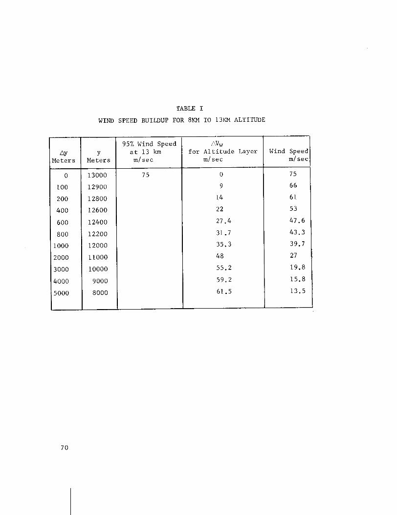
TABLE I
WIND SPEED BUILDUP FOR 8KM TO 13KM ALTITUDE
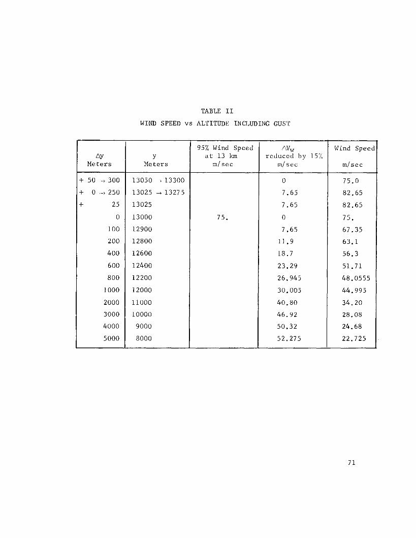
TABLE I1
W I N D SPEED vs ALTITUDE INCLUDING GUST
&' M e t e r s
+ 50 -t 300
+ 0 t 250
+ 25
0
100
200
400
600
800
1000
2000
3000
4000
5000
Wind S p e e d
m / s e c
75.0
82.65
82.65
75.
67.35
63.1
56.3
51.71
48.0555
44.995
34.20
28.08
24.68
22.725
Avw r e d u c e d by 15%
m / s e c
0
7 .65
7.65
0
7.65
11.9
18.7
23.29
26.945
30.005
40.80
46.92
50.32
52.275
Y M e t e r s
13050 - t 13300
13025 -+ 13275
13025
13000
12900
12800
12600
12400
12200
12000
11000
10000
9000
8000
95% Wind S p e e d a t 13 km
m l s e c
75.
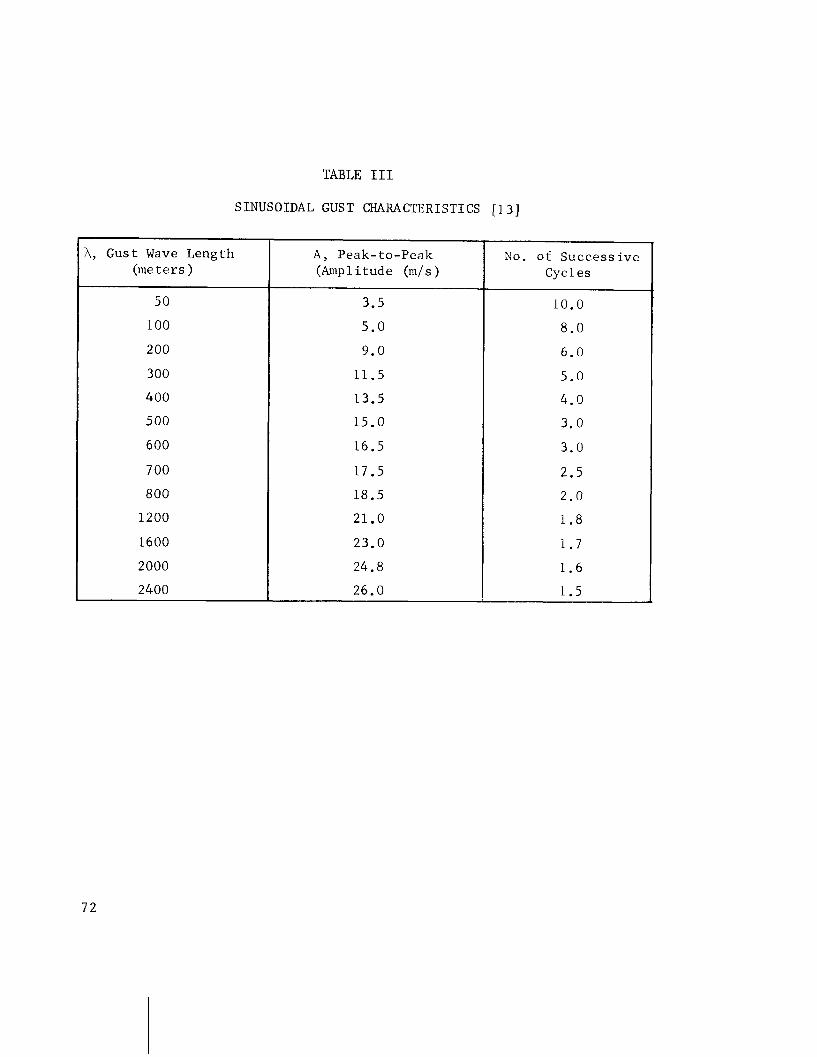
TABLE I11
SINUSOIDAL GUST CHARACTERISTICS [13]
A, Gust Wave Length (meters )
5 0
100
200
300
400
5 00
600
7 00
800
1200
1600
2000
2400
A , Peak- to-Peak (Amplitude (m/s)
3.5
5 .0
9.0
11.5
13.5
15.0
16.5
17.5
18.5
21.0
23.0
24.8
26.0
No. of Success ive Cycles
10.0
8 .0
6.0
5 . 0
4.0
3.0
3.0
2.5
2.0
1 .8
1 . 7
1 .6
1 .5 A
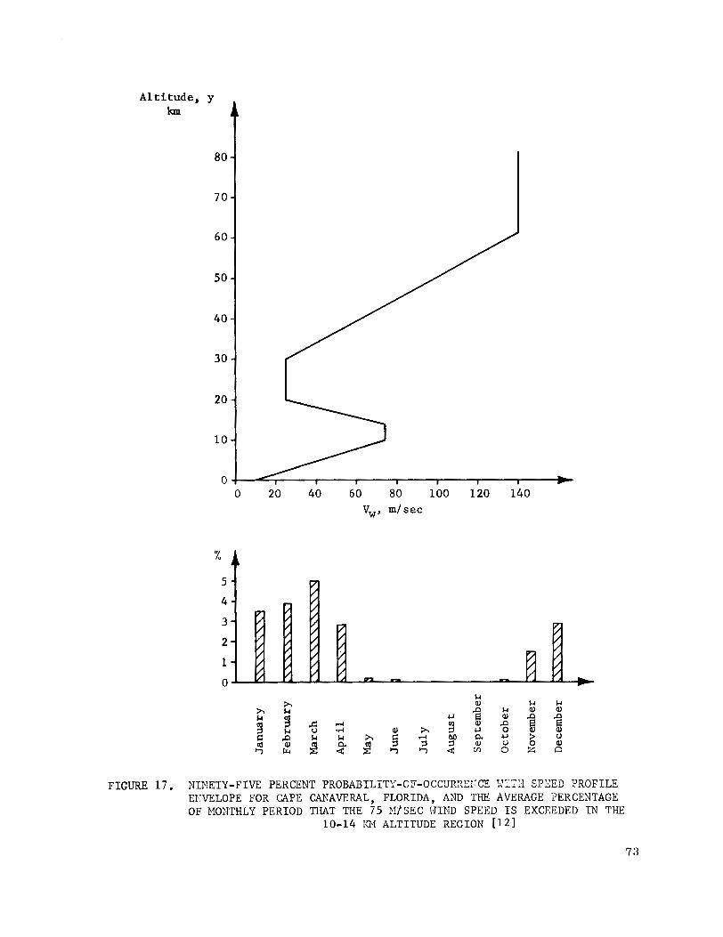
Altitude, km
FIGURE 1 7 . N I ~ ~ E T Y - F I V E PERCENT PROBABILITY-OF-OCCURXEI?CE 1Z'F:l SFBEB PROFILE EKVELOPE FOR CAPE CANAVERAL, FLORIDA, AND THE AVERAGE PERCENTAGE O F MONTHLY PERIOD THAT THE 75 PI /SEC WIND SPEED I S EXCEEDED I N THE
10-14 l3f ALTITUDE REGION [ I21
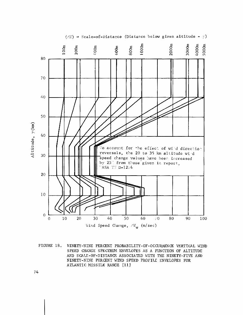
(,/&') = Sca le -o f - l l i s t a~ce (Distar.ce below g iven a l t i t u d e - y )
FIGURE 18. NINETY-NINE PERCENT PROBABILITY-OF-OCCURRENCE VERTICAL WIND SPEED CHANGE SPECTRUM ENVELOPES AS A FUNCTION OF ALTITUDE AND SCALE-OF-DISTANCE ASSOCIATED WITH THE NINETY-FIVE AND NINETY-NINE PERCENT WIND SPEED PROFILE ENVELOPES FOR ATLANTIC M I S S I L E RANGE [ l l ]
::ind Speed (m/sec)
F I G I R E 19. '.vI:D SPEED 3iJ?Z3:JP $OR 8 KM TC 13 -?: ALTITIID?
Time (T U n i t s )
FIGURE PO. lJIND SPEED vs TIME
nd Buildup Envelope
I F F P'- - d e a l i z e d i- d
Speed ~ ' r o f i l e
FIGURE 21. RELATIONSHIP BETWEEN ESTABLISHED GUSTS AND/OR EMBEDDED J E T CHARACTERISTICS (QUASI-SQUARE WAVE SHAPE) AND THE IDEALIZED WIND SPEED PROFILE ENVELOPE
A = 50 to 3 0 h I
.-lvelope 1-7s 9 m/sec
J d e a l i z e d . , i -d peed 'nvelope
FIGURE 22. TYPICAL VEHICLE RESPONSE TO A WIND BUILDUP WITH MAXIMUM PLATEAU
FIGURE 2 3 . TYPICAL VEHICLE RESPONSE TO WIND BUILDUP WITH GUST
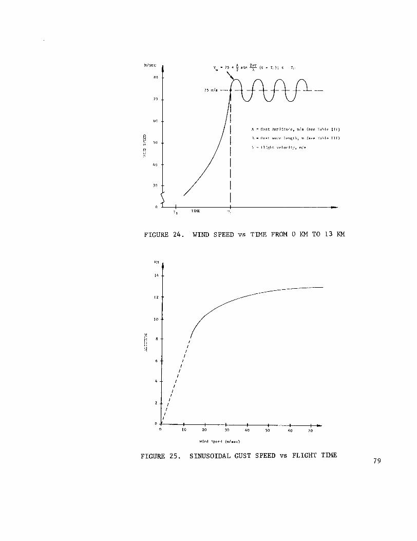
A - Curt h p l t l u , l ~ , m l n (see l a h l p 111)
h - c t l s t wnvc I rnpt l l , m (see T a h l r T I T )
L' - I l l f i l n L v r l o c i t j . , m / a
FIGURE 24. WIND SPEED vs TlME FROM 0 KM TO 13 KM
FIGURE 25. SINUSOIDAL GUST SPEED vs FLIGHT TlME

V I I I . TRANSFER FUNCTIONS AND BLOCK DIAGRAMS
The t r a n s f e r f u n c t i o n s con ta ined i n t h e b lock diagrams a r e most g e n e r a l l y shown i n t h e Laplace v a r i a b l e S .
The Laplace t r a n s f o r m of a t ime f u n c t i o n f ( t ) is d e f i n e d a s
where S i s a complex v a r i a b l e . For F ( s ) t o be mean ingfu l , t h e i n t e g r a l must converge and f ( t ) must be d e f i n e d f o r t > 0 and equa l t o z e r o f o r t 5 0. There a r e l i m i t a t i o n s on t h e f u n c t i o n s f ( t ) t h a t a r e Laplace t r a n s f o r m a b l e . To a s s u r e convergence of the Laplace i n t e g r a l r e q u i r e s t h a t (1) f ( t ) be p iecewise cont inuous over every f i n i t e i n t e r v a l and ( 2 ) t h a t f ( t ) be of e x p o n e n t i a l o r d e r .
Consider f o r example, t h e Laplace t r a n s f o r m of t h e d e r i v a t i v e of x ( t ) . I t i s
which g i v e s t h e r e s u l t
where x(oS) i s the i n i t i a l c o n d i t i o n .
S i m i l a r l y , the Laplace t r a n s f o r m of t h e second d e r i v a t i v e of x ( t ) i s

where
and
a r e i n i t i a l c o n d i t i o n s . The Laplace t r a n s f o r m of o t h e r f u n c t i o n s commonly used i n c o n t r o l t h e o r y can be found i n Refe rences 7 and 8. The o u t s t a n d - ing f e a t u r e s of t h e Laplace t r a n s f o r m a r e i t s a b i l i t y t o c o n v e r t a d i f - f e r e n t i a l e q u a t i o n i n t o a n a l g e b r a i c e q u a t i o n , i t s a b i l i t y t o hand le i n i t i a l c o n d i t i o n s d i r e c t l y , and i t s wide range of a p p l i c a t i o n .
A t r a n s f e r f u n c t i o n e x p r e s s e s the dynamic r e l a t i o n s h i p between o u t - p u t and i n p u t . I n g e n e r a l , the o u t p u t q u a n t i t y of any l i n e a r component of a sys tem i s r e l a t e d t o t h e i n p u t by a g a i n f a c t o r and combinat ions of d e r i v a t i v e s and i n t e g r a l s w i t h r e s p e c t t o t ime.
For example, c o n s i d e r t h e second o r d e r d i f f e r e n t i a l e q u a t i o n
X + a k + bx = K(9 + c y ) .
The r igh t -hand s i d e r e p r e s e n t s the i n p u t o r f o r c i n g f u n c t i o n of t h e sys tem, K r e p r e s e n t s a g a i n f a c t o r , and x r e p r e s e n t s t h e o u t p u t o r r e s p o n s e of t h e s ys tem.
The Laplace t r a n s f o r m of t h i s e q u a t i o n i s
and
The f i r s t term on t h e r igh t -hand s i d e of t h i s e q u a t i o n r e p r e s e n t s t h e t r a n s f e r f u n c t i o n and the second term r e p r e s e n t s the i n i t i a l c o n d i t i o n o p e r a t o r . F r e q u e n t l y i n c o n t r o l s y s tem s t u d i e s , t h e i n i t i a l c o n d i t i o n s a r e made z e r o f o r s i m p l i c i t y . I n t h i s c a s e f o r z e r o i n i t i a l c o n d i t i o n s , t h e r a t i o of o u t p u t t o i n p u t becomes
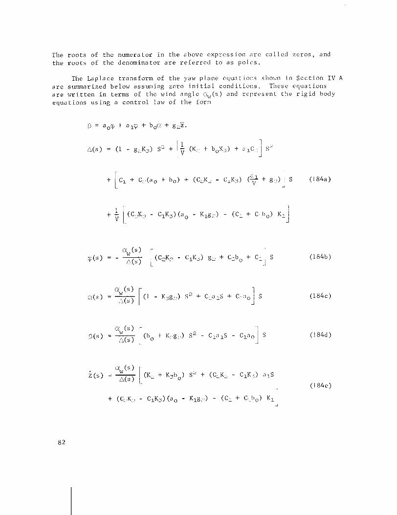
The r o o t s o f t h e numera to r i n t h e above e x p r e s s i o n a r e c a l l e d z e r o s , and t h e r o o t s o f t h e d e n o m i n a t o r a r e r e f e r r e d t o a s po1c.s.
The L a p l a c e t r a n s f o r m o f t h e yaw p l a n e cquo t i o u s shown i n S e c t i o n I V A a r e summarized be low a s suming z e r o i n i t i a l c o n d i t i o n s . These e q u a t i o n s a r e w r i t t e n i n t e rms of t h e wind a n g l e c%,(s) and r e p r t l s e n t t h e r i g i d body e q u a t i o n s u s i n g a c o n t r o l law o f t h e form

Equa t ion (184a) above i s c a l l e d t h e c h a r a c t e r i s t i c e q u a t i o n of t h e s y s tem. Equa t ions (184b) through (184f) a r e t r a n s f e r f u n c t i o n s of t h e r e s p e c t i v e v a r i a b l e s w i t h r e s p e c t t o t h e wind a n g l e ~ & ( s ) . When d r i f t minimum g a i n s (ao, bo, g2) a r e used , the c o n s t a n t term i n e q u a t i o n (184a) and t h e d r i f t e q u a t i o n (184e) a r e z e r o , o r
I n t h i s c a s e , a n S can be f a c t o r e d o u t of t h e A(s) e q u a t i o n and the numerator of t h e t ( s ) e q u a t i o n a s f o l l o w s :
where t h e s u b s c r i p t DM d e n o t e s " d r i f t minimum."
N o t i c e t h a t s u b s t i t u t i n g A(s)DM i n e q u a t i o n s (184b) , (184c) , (184d) , (184f) and ( 1 8 4 i ) , t h e S f a c t o r i n b o t h the numerator and denominator c a n c e l a s a r e s u l t of t h e d r i f t minimum g a i n r e l a t i o n (184g) . So lv ing f o r t h e t h r e e r o o t s of n(s)DM = 0 i n e q u a t i o n (184h) r e v e a l s t h a t one r o o t i s l o c a t e d a t S = 0. S i n c e t h i s r o o t i s l o c a t e d a t . t h e o r i g i n of t h e S p l a n e , i t is commonly r e f e r r e d t o a s t h e " d r i f t r o o t po le . "
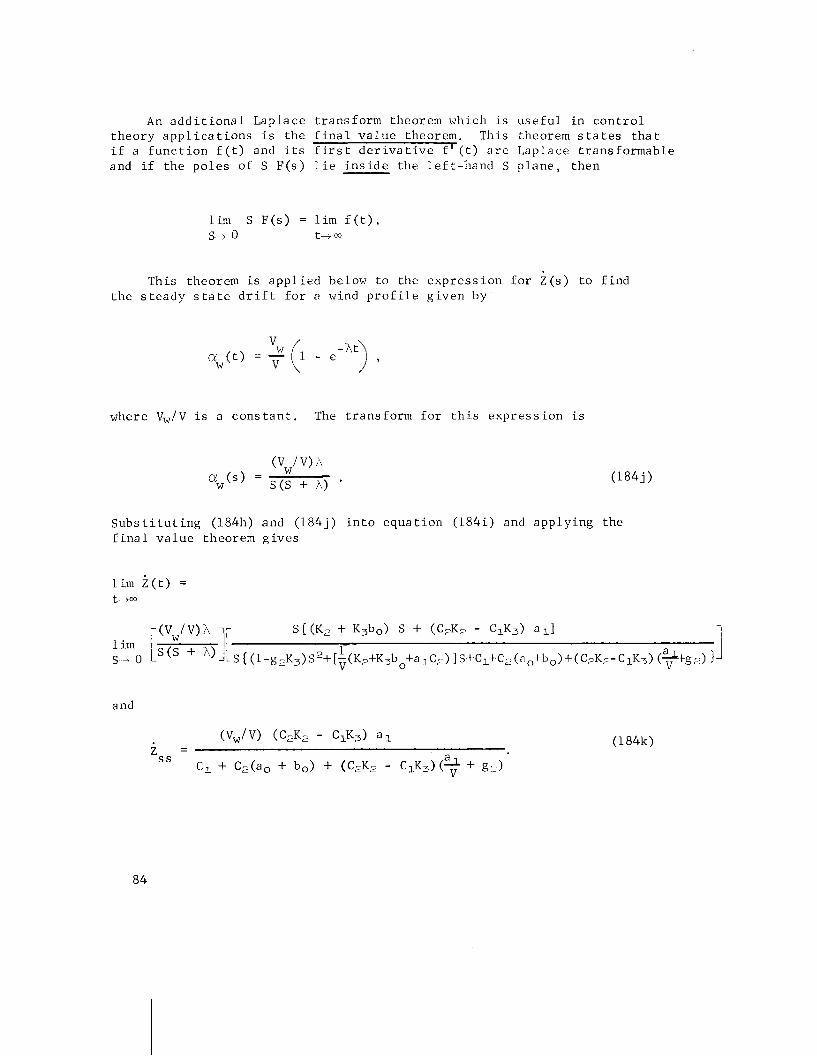
An a d d i t i o n a l Laplace t r ans fo rm theorem which is u s e f u l i n c o n t r o l t heo ry a p p l i c a t i o n s i s t he f i n a l v a l u e theorem. This theorem s t a t e s t h a t i f a f u n c t i o n f ( t ) and i t s f i r s t d e r i v a t i v e f ' ( t ) a r e Laplace t r ans fo rmab le and i f t he p o l e s of S F ( s ) l i e i n s i d e t he l e f t - h a n d S p l a n e , then
l i m S F ( s ) = l i m f ( t ) . S 4 0 t-t 03
This theorern is a p p l i e d below t o t he e x p r e s s i o n f o r Z ( s ) t o f i n d t h e s t e a d y s t a t e d r i f t f o r a wind p r o f i l e g i v e n by
where v,/V i s a c o n s t a n t . The t r ans fo rm f o r t h i s e x p r e s s i o n i s
S u b s t i t u t i n g (184h) and (184j ) i n t o e q u a t i o n (184 i ) and a p p l y i n g t he f i n a l v a l u e theorem g i v e s
and

The same r e s u l t cou ld have been o b t a i n e d f o r iss by u s i n g a s t e p wind % ( t ) = (V,,/V) o r any o t h e r wind p r o f i l e whi.ch conve rges t o a f i n a l v a l u e (v,/V) a s t + m. Hence, t h e . f i n a 1 s t e a d y s t a t e d r i f t i s i n d e p e n d e n t of t h e wind p r o f i l e % ( t ) a s l ong a s i t conve rges t o a f i n a l c o n s t a n t v a l u e .
To i l l u s t r a t e a p p l i c a t i o n o f L a p l a c e t r a n s f o r m t h e o r y t o o b t a i n t r a n s f e r f u n c t i o n s and t h e s u b s e q u e n t c o n s t r u c t i o n of t h e b l o c k d i ag ram, c o n s i d e r t h e f o l l o w i n g s i m p l i f i e d r i g i d body e q u a t i o n s w i t h a t t i t u d e ( q ~ ) and a t t i t u d e r a t e (6) - c o n t r o l . The d r i f t (2) and wind a n g l e (uw) a r e ignored i n t h e s e e q u a t i o n s .
I n t h i s s y s tern of e q u a t i o n s , vc i s t h e commanded a t t i t u d e o f t h e v e h i c l e and a c t s a s t h e f o r c i n g f u n c t i o n . The o u t p u t o f t h e s y s t e m o r t h e con- t r o l l e d v a r i a b l e i s Q.
Taking t h e L a p l a c e t r a n s f o r m f o r z e r o i n i t i a l cond i t i o n s , s o l v i n g f o r t h e t r a n s f e r f u n c t i o n Q t o B and u s i n g t h e f i r s t two e q u a t i o n s r e s u l t s i n t h e f o l l o w i n g r i g i d body t r a n s f e r f u n c t i o n
Th i s can be r e p r e s e n t e d by t h e f o l l o w i n g b l o c k d i a g r a m and i s r e f e r r e d t o a s open l o o p c o n t r o l .

The t h i r d e q u a t i o n i n the above system of e q u a t i o n s r e p r e s e n t s t h e eng ine d e f l e c t i o n B i n r e sponse t o the commanded a t t i t u d e vC and feed- back from t h e a t t i t u d e g y r o cp and r a t e gyro &. This e q u a t i o n is r e p r e - s e n t e d by t h e fo l lowing b locks and summing j u n c t i o n .
Combining the above two b lock diagrams r e s u l t s i n t h e fo l lowing c losed loop a t t i t u d e c o n t r o l s y s tem.
Most p r a c t i c a l c o n t r o l systems a r e much more compl icated than t h e s i m p l i f i e d i l l u s t r a t i v e example g iven above and of t e n c o n t a i n m u l t i p l e feedback loops and s e v e r a l i n p u t s .
By means of b l o c k diagram r e d u c t i o n theorems (References 7 and 8 ) , e v e r y b l o c k diagram can be reduced t o i s o l a t e parameters i n a t r a n s f e r f u n c t i o n ( i f n e c e s s a r y t o s t u d y i t s e f f e c t s ) o r can be reduced t o t h e b a s i c b l o c k diagram a s shown i n F i g u r e 26. The b lock diagram r e d u c t i o n p rov ides a t echn ique t o r educe the s y s tem t o a form which can be s t u d i e d i n terms of g e n e r a l feedback t h e o r y .
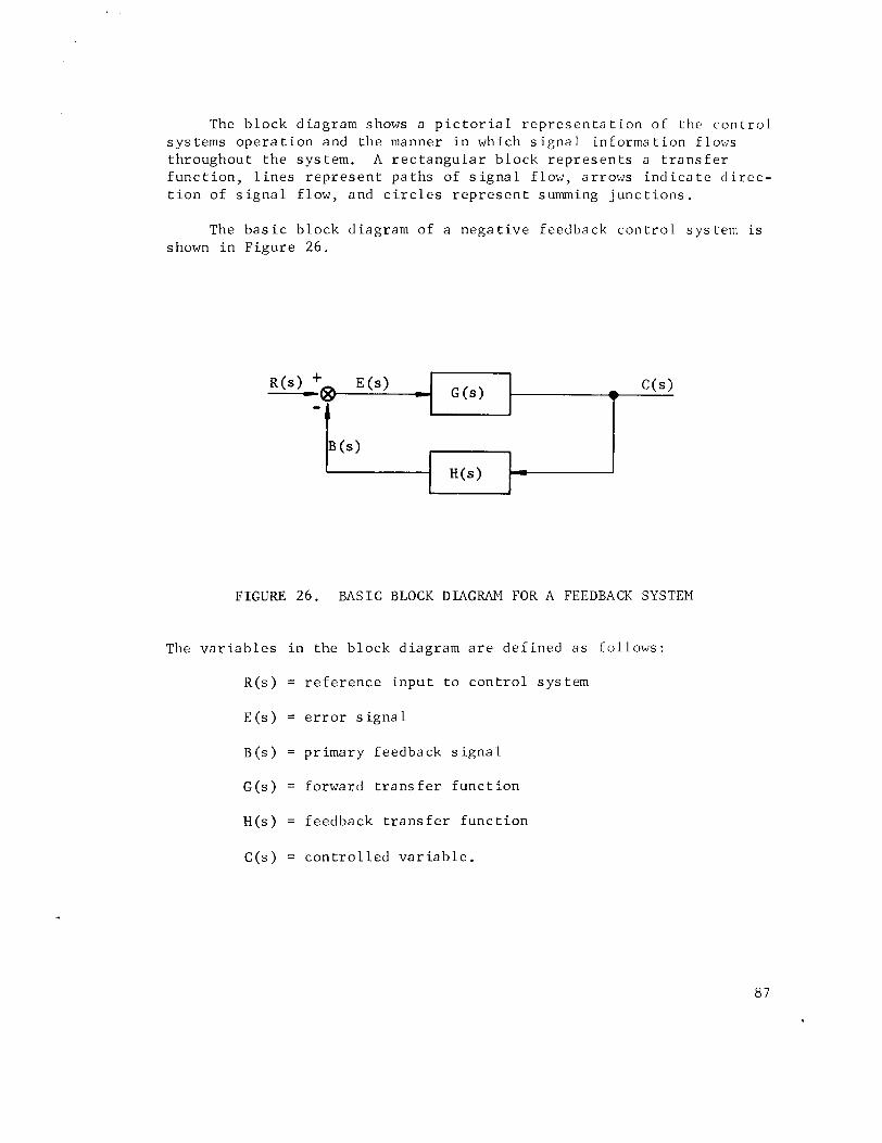
The b l o c k d i a g r a m shows a p i c t o r i a l r e p r e s e n t a t i o n o f t h e c o n t r o l s y s tems ope ra t i o n and t h e manner i n which s i g n a l in forma t i o n f 1ot:s t h r o u g h o u t t h e s y s tem. A r e c t a n g u l a r b l o c k r e p r e s e n t s a t r a n s f e r f u n c t i o n , l i n e s r e p r e s e n t p a t h s o f s i g n a l f l o w , a r r o w s i n d i c a t e d i r e c - t i o n of s i g n a l f l o w , and c i r c l e s r e p r e s e n t summing j u n c t i o n s .
The b a s i c b l o c k d i a g r a m o f a n e g a t i v e f e e d b a c k c o n t r o l s y s tern i s shown i n F i g u r e 26.
FIGURE 26. BASIC BLOCK DIAGRAM FOR A FEEDBACK SYSTEM
The v a r i a b l e s i n t h e b l o c k d i a g r a m a r e d e f i n e d a s f o l l o w s :
R ( s ) = r e f e r e n c e i n p u t t o c o n t r o l s y s t e m
E ( s ) = e r r o r s i g n a l
B ( s ) = p r i m a r y f e e d b a c k s i g n a l
G ( s ) = fo rward t r a n s f e r f u n c t i o n
H ( s ) = f e e d b a c k t r a n s f e r f u n c t i o n
C ( s ) = c o n t r o l l e d v a r i a b l e .
From t h e block diagram shown above, t h e fo l lowing r e l a t i o n s can b e w r i t t e n r e l a t i n g t h e v a r i a b l e s of t h e system.
Solving e q u a t i o n s (185), (186) and (187) f o r t h e c o n t r o l r a t i o c ( s ) /R(s ) , we o b t a i n t h e c losed- loop t r a n s f e r f u n c t i o n
Solving e q u a t i o n s (186) and (187) f o r B(s ) /E ( s ) , we o b t a i n the open-loop t r a n s f e r f u n c t i o n
The c h a r a c t e r i s t i c e q u a t i o n of t h e system i s t h e denominator of t h e c losed- loop t r a n s f e r f u n c t i o n o r
The fo rego ing e q u a t i o n s a r e w r i t t e n assuming b o t h G(s) and H(s) a r e p o s i t i v e . Obviously, G(s) and H(s) may occur w i t h o t h e r s i g n combina- t i o n s . Negat ive feedback w i l l always occur , though, when t h e feedback s i g n a l B(s ) and i n p u t s i g h a l R(s ) d i f f e r i n s i g n , and p o s i t i v e feedback w i l l occur when they b o t h a g r e e i'n s i g n . P o s i t i v e feedback systems a r e o f t e n u n s t a b l e s i n c e t h i s s i g n a l h a s t h e c o r r e c t phase f o r r e g e n e r a t i o n t o t a k e p l a c e around t h e feedback loop; and, i f t h e ampl i tude of t h e feedback i s s u f f i c i e n t , s u s t a i n e d o s c i l l a t i o n s w i l l r e s u l t .
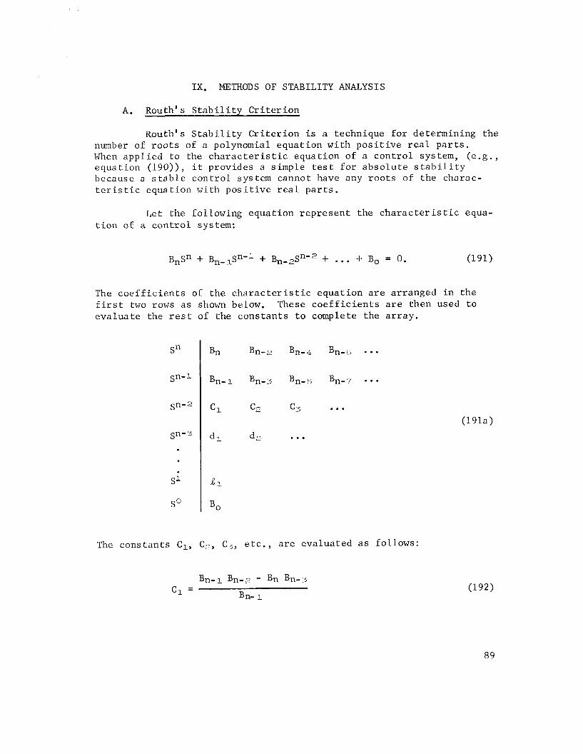
IX . METHODS OF STABILITY ANALYSIS
A. ~ o u t h ' s S t a b i l i t y C r i t e r i o n
~ o u t h ' s S t a b i l i t y C r i t e r i o n i s a technique f o r determining the number of r o o t s of a polynomial equat ion wi th p o s i t i v e r e a l p a r t s . When appl ied t o the c h a r a c t e r i s t i c equat ion of a con t ro l system, ( e .g . , equat ion (190)) , i t provides a simple t e s t f o r abso lu t e s t a b i l i t y because a s t a b l e con t ro l system cannot have any roo t s of the charac- t e r i s t i c equat ion wi th p o s i t i v e r e a l p a r t s .
Let the following equat ion r ep re sen t the c h a r a c t e r i s t i c equa- t i o n of a con t ro l system:
The c o e f f i c i e n t s of the c h a r a c t e r i s t i c equat ion a r e arranged i n t he f i r s t two rows a s shown below. These c o e f f i c i e n t s a r e then used t o eva lua t e the r e s t of the cons tan ts t o complete the a r r ay .
The cons tan ts C,, C,, C3, e t c . , a r e evaluated a s follows:
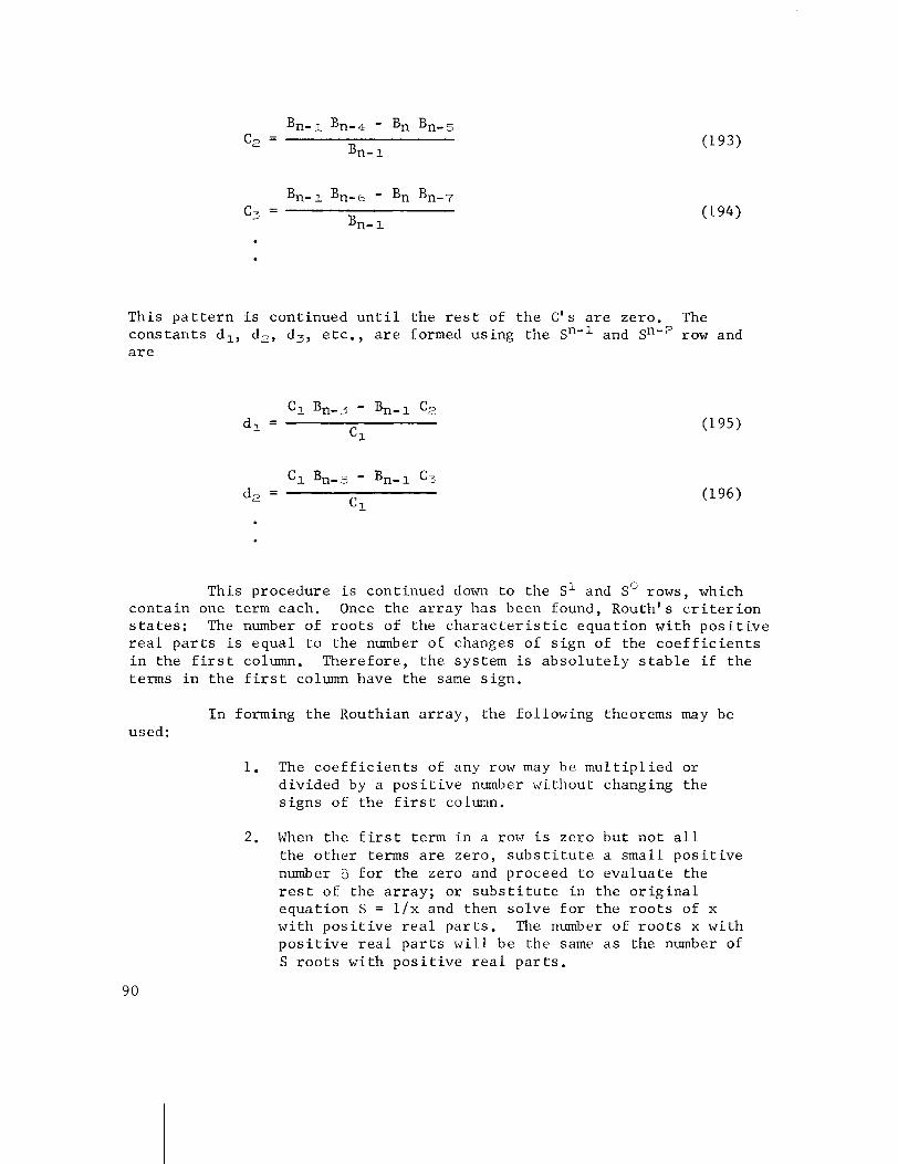
This p a t t e r n i s continued u n t i l the r e s t of t he C's a r e zero. The cons tan ts dl, d2, d3, e t c . , a r e formed using the snel and sn-' row and a r e
This procedure i s continued down t o the s1 and S" rows, which .on ta in one term each. Once the a r r a y has been found, Routh's c r i t e r i o n t a t e s : The number of r o o t s of the c h a r a c t e r i s t i c equat ion wi th p o s i t i v e
r e a l p a r t s i s equal t o the number of changes of s i g n of the c o e f f i c i e n t s i n t he f i r s t column. Therefore, t he system i s abso lu t e ly s t a b l e i f the terms i n t h e f i r s t column have the same sign.
I n forming the Routhian a r r a y , the following theorems may be used:
1. The c o e f f i c i e n t s of any row may be mu l t ip l i ed or divided by a p o s i t i v e number without changing the s igns of the f i r s t column.
2. When the f i r s t term i n a row i s zero but no t a l l the o the r terms a r e zero, s u b s t i t u t e a small p o s i t i v e number 5 f o r the zero and proceed t o eva lua te the r e s t of the a r r a y ; o r s u b s t i t u t e i n the o r i g i n a l equat ion S = l / x and then so lve f o r the r o o t s of x wi th p o s i t i v e r e a l pa r t s . The number of r o o t s x with p o s i t i v e r e a l p a r t s w i l l be the same a s the number of S r o o t s wi th p o s i t i v e r e a l p a r t s .
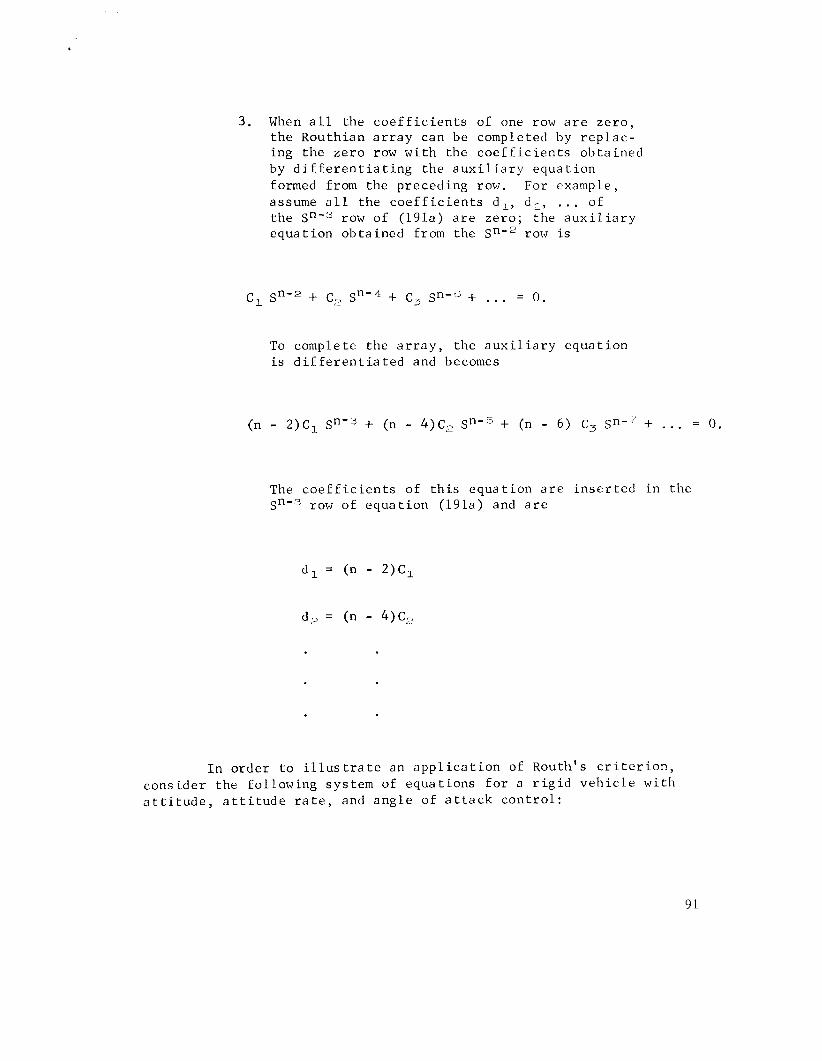
3 . When a l l t h e c o e f f i c i e n t s of one row a r e z e r o , t h e Routhian a r r a y can be completed by r e p l a c - ing t h e z e r o row w i t h the c o e f f i c i e n t s o b t a i n e d by d i f f e r e n t i a t i n g t h e a u x i l i a r y e q u a t i o n formed from the p reced ing row. For example, assume a l l the c o e f f i c i e n t s d l , d,, . . . of t h e Sn'3 row of (191a) a r e z e r o ; t h e a u x i l i a r y e q u a t i o n o b t a i n e d from the sn--' row i s
To complete the a r r a y , the a u x i l i a r y e q u a t i o n i s d i f f e r e n t i a t e d and becomes
The c o e f f i c i e n t s of t h i s e q u a t i o n a r e i n s e r t e d i n the row of e q u a t i o n (191a) and a r e
I n o r d e r t o i l l u s t r a t e an a p p l i c a t i o n of ~ o u t h ' s c r i t e r i o n , c o n s i d e r the fo l lowing sys tem of e q u a t i o n s f o r a r i g i d v e h i c l e w i t h a t t i t u d e , a t t i t u d e r a t e , and a n g l e of a t t a c k c o n t r o l :

T h i s system of e q u a t i o n s can be reduced t o t h r e e e q u a t i o n s i n t h r e e unknowns by e l i m i n a t i n g the Z v a r i a b l e between e q u a t i o n s (198) and (199). Then talcing t h e Laplace t r ans form of the system f o r z e r o i n i t i a l c o n d i t i o n s of t h e v a r i a b l e s cp, a, /3 and Z, we g e t
o r , w r i t t e n i n m a t r i x form,
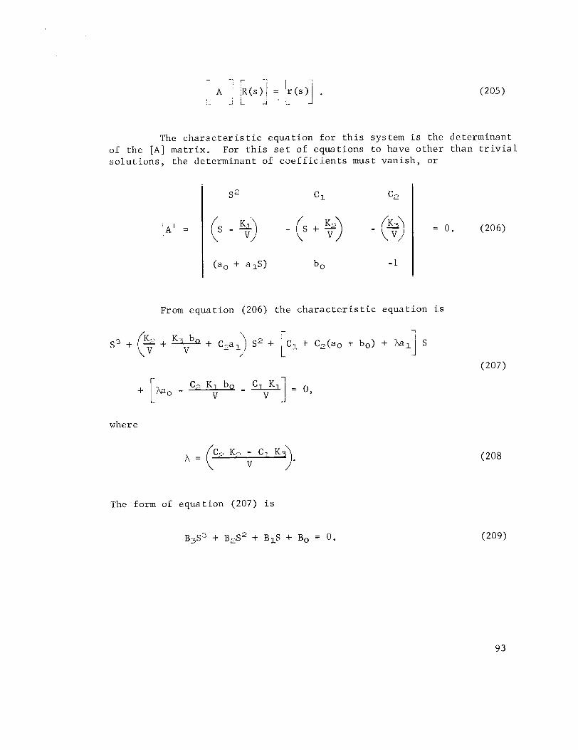
The c h a r a c t e r i s t i c equa t ion f o r t h i s sy s tern i s the determinant of the [A] matr ix . For t h i s s e t of equat ions t o have o the r than t r i v i a l s o l u t i o n s , the determinant of c o e f f i c i e n t s must van i sh , o r
From equat ion (206) the c h a r a c t e r i s t i c equa t ion i s
where
The form of equa t ion (207) i s
B ~ S ' + ~ $ 3 ~ + BIS + Bo = 0.
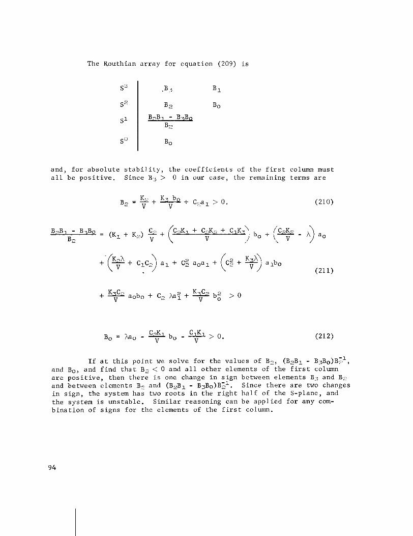
The Routhian a r r a y f o r e q u a t i o n (209) i s
and , f o r a b s o l u t e s t a b i l i t y , t h e c o e f f i c i e n t s of t h e f i r s t column must a l l be p o s i t i v e . S ince B3 > 0 i n our c a s e , t h e remaining terms a r e
B7Bl - B3Bo = C (K, + K,) -2 +
V V ,) bo + (T - A) a. B 2 (CpK1 + C7K7 + CIK:\
I f a t t h i s p o i n t we s o l v e f o r t h e v a l u e s of B?, (B2B1 - B ~ B ~ ) B > ~ , and B o y and f i n d t h a t B2 < 0 and a l l o t h e r e lements of t h e f i r s t column a r e p o s i t i v e , then t h e r e i s one change i n s i g n between e lements B3 and B; and between e lements B2 and (B2B1 - B ~ B ~ ) B ; ~ . Since t h e r e a r e two changes i n s i g n , t h e sys tem h a s two r o o t s i n t h e r i g h t h a l f of t h e S-plane, and t h e sys tem is u n s t a b l e . S i m i l a r r eason ing can be a p p l i e d f o r any com- b i n a t i o n of s i g n s f o r t h e e lements of t h e f i r s t column.

I n t h e above c a s e , we were a b l e t o de te rmine the s t a b i l i t y of t h e sys tem f o r a p a r t i c u l a r v a l u e of g a i n s a o , a , and bo and sys tem c o n s t a n t s C i , K i and V. A b e t t e r p i c t u r e of t h e sys tem s t a b i l i t y can be shown by p l o t t i n g t h e s t a b i l i t y boundar ies i n t h e g a i n p lane ( a o , b o ) , (ao, a l ) o r ( a l , bo) . The s t a b i l i t y boundar ies co r respond t o t h e r o o t s of S f o r which t h e r e a l p a r t i s z e r o . I n t h i s c a s e , e q u a t i o n s (210) , (211) and (212) a r e equa ted t o z e r o and t h e e q u a t i o n s of the s t a b i l i t y boundar ies a r e
Equa t ions (213) and (214) r e p r e s e n t t h e dynamic s t a b i l i t y boundary and correspond t o t h e e lements o f t h e f i r s t column of t h e Routhian a r r a y e x c l u s i v e of t h e Bo e lement . Equa t ion (215) r e p r e s e n t s a s t a b i l i t y boundary which can be recogn ized a s t h e " d r i f t minimum" con- t r o l g a i n r e l a t i o n . Th i s r e l a t i o n i s r e f e r r e d t o a s the " s t a t i c " s t a b i l i t y boundary, o r s imply the t r i m c o n d i t i o n f o r s t a b i l i t y .
I n o r d e r t o p l o t t h e s t a b i l i t y boundar ies i n t h e (ao , bo) p l a n e , e q u a t i o n s (213) through (215) a r e w r i t t e n i n t h e fo l lowing form:
bo = k,; (B, = 0) (216)

Typica l v a l u e s of t h e c o n s t a n t s f o r a l a r g e b o o s t e r a t t h e time of maximum dynamic p r e s s u r e a r e
and t h e r e f o r e ,
The s t a b i l i t y boundar ies , us ing t h e above c o n s t a n t s and equa- t i o n s (216) through (218) f o r a c o n s t a n t g a i n of a l = l , a r e shown i n F i g u r e 27. We s e e t h a t t h e B2 = 0 s t a b i l i t y boundary i s a s t r a i g h t l i n e w i t h a s l o p e m = 0 and bo i n t e r c e p t

For a l = 1.0
F I G U R E 27. S T A B I L I T Y BOUNDARIES I N THE (ao, bo) G A I N PLANE U S I N G ROUTH'S S T A B I L I T Y C R I T E R I O N
97
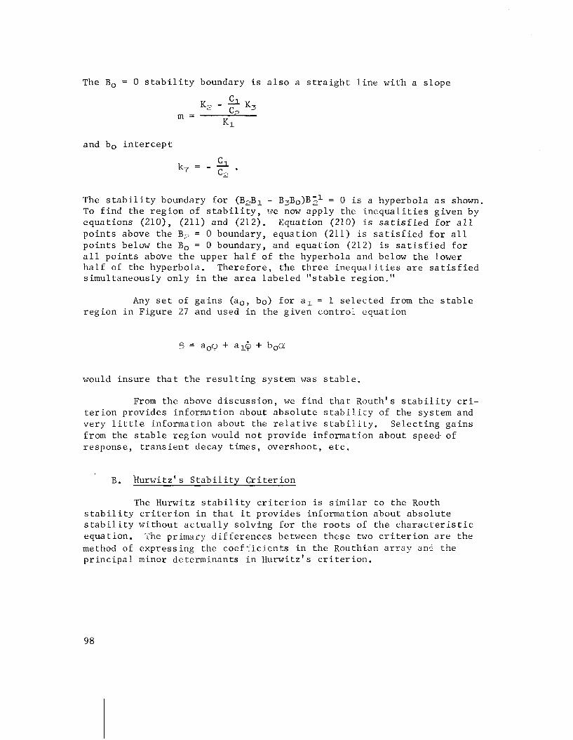
The Bo = 0 s t a b i l i t y boundary i s a l s o a s t r a i g h t l i n e w i t h a s l o p e
and bo i n t e r c e p t
The s t a b i l i t y boundary f o r (B2B1 - B ~ B ~ ) B ~ ~ = 0 i s a hyperbo la a s shown. To f i n d t h e r e g i o n of s t a b i l i t y , we now a p p l y the i n e q u a l i t i e s g i v e n by e q u a t i o n s (210) , (211) and (212). Equat ion (210) i s s a t i s f i e d f o r a l l p o i n t s above t h e B, = 0 boundary, e q u a t i o n (211) i s s a t i s f i e d f o r a l l p o i n t s below t h e Bo = 0 boundary, and e q u a t i o n (212) is s a t i s f i e d f o r a l l p o i n t s above t h e upper h a l f of t h e hyperbo la and below t h e lower h a l f of t h e hyperbo la . T h e r e f o r e , t h e t h r e e i n e q u a l i t i e s a r e s a t i s f i e d s i m u l t a n e o u s l y o n l y i n t h e a r e a l a b e l e d " s t a b l e r eg ion . "
Any s e t of g a i n s ( ao , bo) f o r a l = 1 s e l e c t e d from the s t a b l e r e g i o n i n F i g u r e 27 and used i n t h e g i v e n c o n t r o l e q u a t i o n
would i n s u r e t h a t t h e r e s u l t i n g sys tem was s t a b l e .
From t h e above d i s c u s s i o n , we f i n d t h a t Rou th ' s s t a b i l i t y c r i - t e r i o n p r o v i d e s inforrna t i o n abou t a b s o l u t e s t a b i l i t y of the sys tem and v e r y l i t t l e i n f o r m a t i o n abou t t h e r e l a t i v e s t a b i l i t y . S e l e c t i n g g a i n s from t h e s t a b l e r e g i o n would n o t p rov ide i n f o r m a t i o n abou t s p e e d of r e s p o n s e , t r a n s i e n t decay t imes , o v e r s h o o t , e t c .
B. ~ u r w i t z ' s S t a b i l i t y C r i t e r i o n
The Hurwitz s t a b i l i t y c r i t e r i o n is s i m i l a r t o t h e Routh s t a b i l i t y c r i t e r i o n i n t h a t i t p r o v i d e s i n f o r m a t i o n abou t a b s o l u t e s t a b i l i t y w i t h o u t a c t u a l l y s o l v i n g f o r t h e r o o t s of t h e c h a r a c t e r i s t i c e q u a t i o n . The pr imary d i f f e r e n c e s between t h e s e two c r i t e r i o n a r e t h e method of e x p r e s s i n g the c o e f f i c i e n t s i n t h e Routhian a r r a y a n < t h e p r i n c i p a l minor de te rminan t s i n ~ u r w i t z ' s c r i t e r i o n .
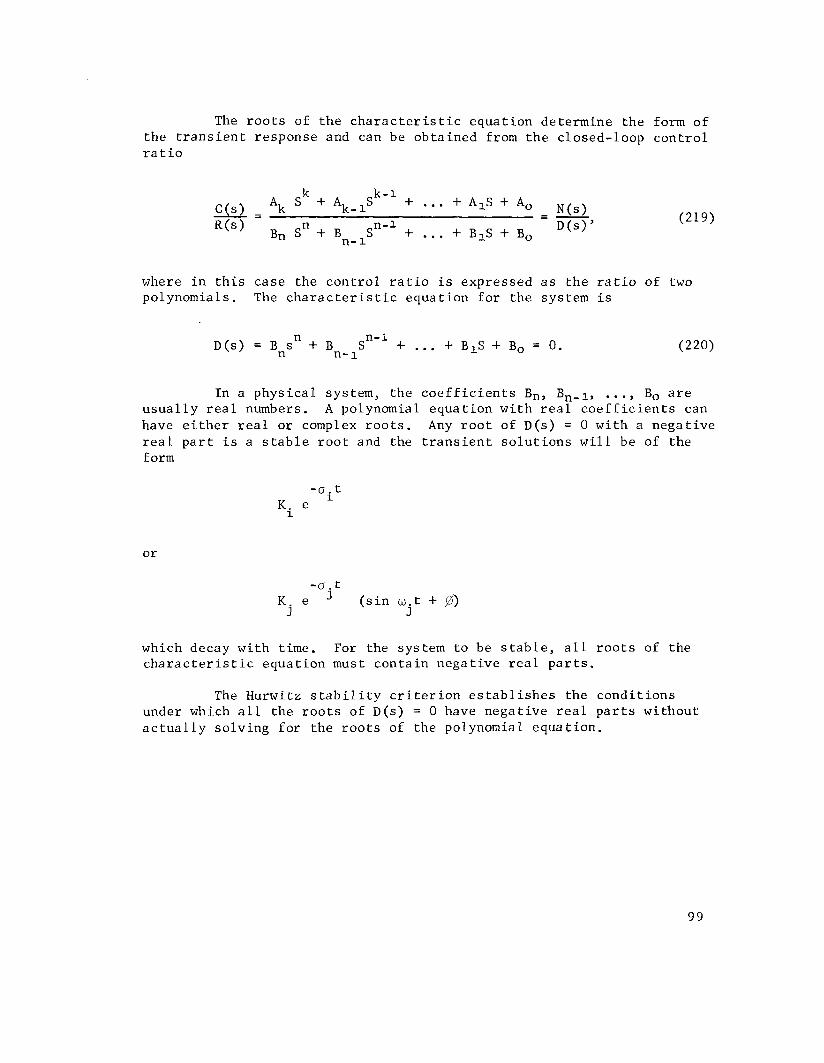
The r o o t s of t h e c h a r a c t e r i s t i c e q u a t i o n d e t e r m i n e t h e form o f t h e t r a n s i e n t r e sponse and can be o b t a i n e d from t h e c losed- loop c o n t r o l r a t i o
where i n t h i s c a s e t h e c o n t r o l r a t i o i s e x p r e s s e d a s t h e r a t i o o f two polynomials . The c h a r a c t e r i s t i c e q u a t i o n f o r t h e sys tem i s
I n a p h y s i c a l sys tem, t h e c o e f f i c i e n t s Bn, B,-l, ..., Bo a r e u s u a l l y r e a l numbers. A polynomial e q u a t i o n w i t h r e a l c o e f f i c i e n t s can have e i t h e r r e a l o r complex r o o t s . Any r o o t o f D(s) = 0 w i t h a n e g a t i v e r e a l p a r t i s a s t a b l e r o o t and the t r a n s i e n t s o l u t i o n s w i l l be of t h e form
- 0 . t
K . e ( s i n w . t + @) J J
which decay w i t h t ime. For the sys tem t o be s t a b l e , a l l r o o t s of t h e c h a r a c t e r i s t i c e q u a t i o n must c o n t a i n n e g a t i v e r e a l p a r t s .
The Hurwitz s t a b i l i t y c r i t e r i o n e s t ab1 i s h e s t h e c o n d i t i o n s under which a l l t h e r o o t s of D(s) = 0 have n e g a t i v e r e a l p a r t s w i t h o u t a c t u a l l y s o l v i n g f o r t h e r o o t s of t h e polynomial e q u a t i o n .

The nth o r d e r Hurwitz de te rminan t i s c o n s t r u c t e d from t h e c o e f f i c i e n t s of e q u a t i o n (220) a s fo l lows :
The p r i n c i p a l minor d e t e r m i n a n t s .Ai oT the Hurwitz d e t e r m i n a n t An a r e d e f i n e d a s
The Hurwitz c r i t e r i o n then can be s t a t e d a s f o l l o w s : The n e c e s s a r y and s u f f i c i e n t c o n d i t i o n s t h a t a l l r o o t s of the polynomial D(s) = 0 have n e g a t i v e r e a l p a r t s a r e t h a t Bn > 0, > 0, fiL > 0, .. • 9
n, > o .
C . Root Locus
The r o o t l o c u s method was I i r s t dev i sed by W . R. Evans i n 1948. Since t h a t t ime, i t h a s become a v e r y usci-ul method of a n a l y s i s and s y n t h e s i s of c o n t r o l sys tems.
The r o o t l o c u s i s a p l o t of the r o o t s of t h e c h a r a c t e r i s t i c e q u a t i o n a s a f u n c t i o n o f g a i n i n t h e complex S-plane. The p o l e s of the t r a n s i e n t r e sponse mode C(S) /R(S) a r e r e l a t e d t o the ze ros and p o l e s of t h e open-loop t r a n s f e r f u n c t i o n B ( s ) / E ( s ) and t h e g a i n K. The r e l a - t i o n s h i p is shown below, where G(s) and H(s) a r e expressed a s the r a t i o of two polynomia 1 e q u a t i o n s .
100

C(s) - G ( s ) - - N I / D , N N ' R(s) 1 + G(s) H(s) 1 + 1 2
Dl D 2
The r o o t s of M 1 N 2 = 0 i n e q u a t i o n (227) a r e c a l l e d t h e z e r o s of t h e open-loop t r a n s f e r f u n c t i o n G(s) H(s) and t h e r o o t s of DID, = 0 a r e c a l l e d t h e p o l e s of the open-loop t r a n s f e r f u n c t i o n G(s ) H(s) . S i m i l a r l y , t h e r o o t s of 1 + N1N2/~1D2 = 0 a r e c a l l e d t h e p o l e s of the c l o s e d - l o o e t r a n s f e r f u n c t i o n c ( s ) / R ( s ) and de te rmine t h e o p e r a t i n g r o o t l o c a t i o n s cor respond ing t o the s y s tem time c o n s t a n t s . The numerator N ~ / D ~ of t h e c o n t r o l r a t i o C ( s ) / R ( s ) merely m o d i f i e s the c o e f f i c i e n t s o f t h e t r a n s i e n t components.
The c h a r a c t e r i s t i c e q u a t i o n of t h e s y s tern is from e q u a t i o n (228)
The l o c a t i o n of t h e r o o t s of the c h a r a c t e r i s t i c e q u a t i o n v a r y a s t h e g a i n K i s v a r i e d . The p l o t of t h e s e r o o t s a s a f u n c t i o n of the g a i n K, where K v a r i e s from z e r o t o i n f i n i t y , i s c a l l e d t h e r o o t l o c u s . --
To e s t a b l i s h two impor tan t c r i t e r i a t h a t a r e u s e f u l i n p l o t t i n g t h e r o o t l o c u s , i t is conven ien t t o e x p r e s s t h e t r a n s f e r f u n c t i o n G ( s ) H(s) a s t h e p roduc t of l i n e a r f a c t o r s .in t h e f o l l o w i n g form:
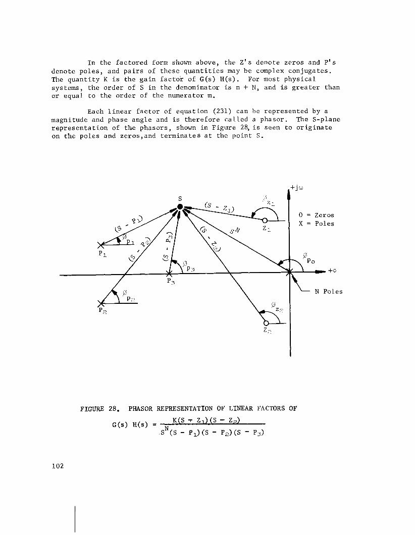
In the f ac to red form shown above, the Z ' s denote zeros and P ' s denote poles , and p a i r s of these q u a n t i t i e s may be complex conjugates . The quan t i t y K i s the ga in f a c t o r of G(s) H(s). For most physical systems, t he order of S i n the denominator i s n + N , and i s g r e a t e r than o r equal t o the order of the numerator m.
Each l i n e a r f a c t o r of equat ion (231) can be represented by a magnitude and phase angle and i s t he re fo re c a l l e d a phasor. The S-plane r e p r e s e n t a t i o n of the phasors, shown i n Figure 28, i s seen t o o r i g i n a t e on the poles and zeros,and te rmina tes a t the poin t S .
FIGURE 28. PHASOR REPRESENTATION OF LINEAR FACTORS OF

The magnitude of a p a r t i c u l a r phasor , s a y (S - P1) where S =-a + j w and P1 =-upl + jwp,, w i l l be
and t h e corresponding phase a n g l e w i l l be
The l i n e a r f a c t o r s i n r e c t a n g u l a r form can then be r e l a t e d t o t h e p o l a r form a s fo l lows :
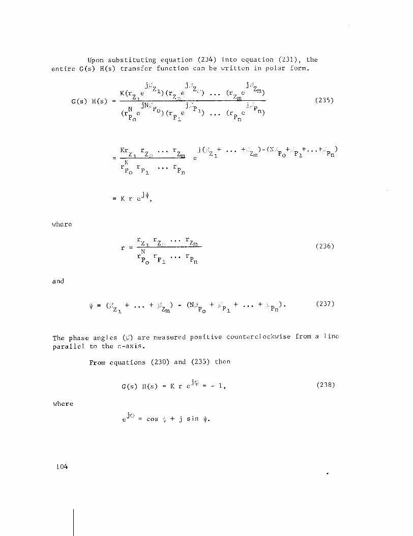
Upon s u b s t i t u t i n g e q u a t i o n (234) i n t o e q u a t i o n (231) , the e n t i r e G(s) H(s) t r a n s f e r f u n c t i o n can be w r i t t e n i n p o l a r form.
where
and
The phase a n g l e s (IJ;) a r e measured p o s i t i v e coun te rc lockwise from a l i n e p a r a l l e l t o t h e a - a x i s .
From e q u a t i o n s (230) and (235) then
where
e J o = cos $ + j s i n 11.

The magnitude of G(s) H(s) i s
IG(s) H ( s ) / = I K r (cos + j s i n I/r)I = I K rl = 1.
The g a i n f a c t o r K may be p o s i t i v e o r negat ive. For K > 0,
G(s) H(s) = K r (cos I) + j s i n $) = -1
= C O S $ = -1,
s i n c e K r = 1 and j = 0 f o r G(s) H(s) t o be a r e a l number. From equa- t i o n (240) the phase angle of G(s) H(s) becomes odd mul t ip l e s of n,
= (2k + 1)n , k = 0 + 1, ? 2, ... For K < 0,
G(s) H(s) = - K r (cos $ + j s i n $) = -1
- - - cos $ = -1,
and the phase angle becomes even m u l t i p l e s of n,
In summary, the two c r i t e r i a t h a t a r e r equ i r ed i n p l o t t i n g t h e r o o t l o c i of a system a r e the phase c r i t e r i o n and magnitude c r i t e r i o n .
Phase C r i t e r i o n
where

Magnitude C r i t e r i o n
where II denotes t h e p r o d u c t of t h e r ' s .
The r o o t l o c u s i s p l o t t e d by f i n d i n g a l l p o i n t s i n t h e S-plane which s a t i s f y t h e phase c r i t e r i o n . A f t e r t h e l o c u s i s complete ly p l o t t e d , t h e magnitude c r i t e r i o n i s used t o s c a l e i t i n terms of t h e v a l u e s of g a i n K . t h a t correspond t o p a r t i c u l a r r o o t s a long t h e locus . The fol low- ing procedure i s h e l p f u l i n c o n s t r u c t i n g t h e r o o t locus :
1. Obtain t h e open-loop t r a n s f e r f u n c t i o n and p u t i t i n t h e form
K ( S - Z1) (S- Z2) ... (S - Zm) G(s) H(s ) = N
s ( S - P1)(S - P,) ... (S - Pn)
and p l o t t h e ze rosZi and p o l e s Pi i n t h e S-plane u s i n g t h e same s c a l e f o r b o t h t h e r e a l a x i s and imaginary a x i s . Continuous curves s t a r t a t each p o l e of G(s) H(s) f o r K = 0 and t e r m i n a t e on t h e z e r o s of G(s) H(s) f o r K = m.
Draw t h e l o c i a long those s e c t i o n s of t h e r e a l a x i s which a r e t o t h e l e f t of an odd number of r e a l p o l e s and ze ros when K i s p o s i t i v e . When K is n e g a t i v e , t h e l o c u s l i e s t o t h e l e f t of a n even number of r e a l p o l e s and z e r o s . This r u l e is a r e s u l t of a p p l y i n g t h e phase a n g l e c r i t e r i o n t o a p o i n t S a s i t is moved a long t h e o -ax i s . The n e t phase a n g l e c o n t r i b u t i o n of phasors o r i g i n a t i n g from ccmplex con juga te p o l e s and z e r o s t o t h e p o i n t S on t h e o - a x i s i s z e r o and may be n e g l e c t e d . For the p a r t i c u l a r po le z e r o c o n f i g u r a t i o n shown below, t h e r e a l a x i s p o r t i o n of the r o o t l o c u s i s shown by a p p l i c a t i o n of t h i s r u l e .
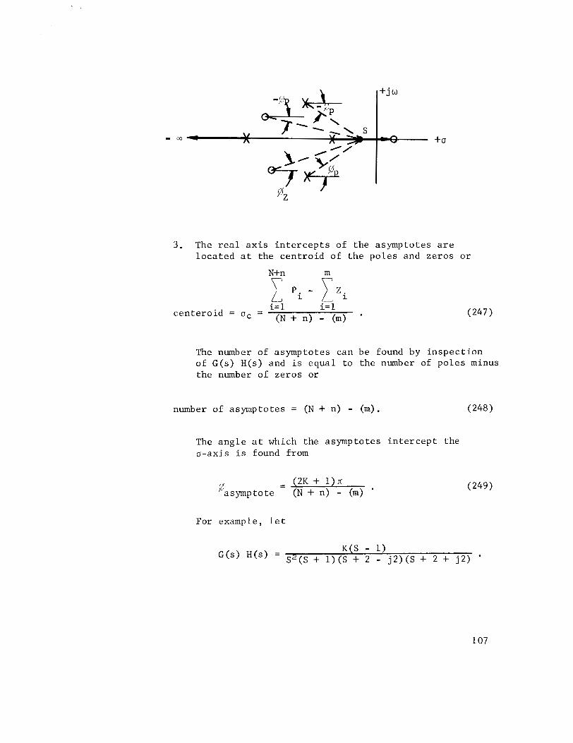
3 . The r e a l a x i s i n t e r c e p t s of the asymptotes a r e loca ted a t the cen t ro id of the poles and zeros o r
\ \
i, 'i - j_lzi i= 1 i= 1
centero id = a, = (N + n) - (m) '
The number of asymptotes can be found by in spec t ion of G(s) H(s) and i s equal to the number of po les minus the number of zeros or
number of asymptotes = (N + n) - (m). (248
The angle a t which the asymptotes i n t e r c e p t the u-axis i s found from
For example, l e t
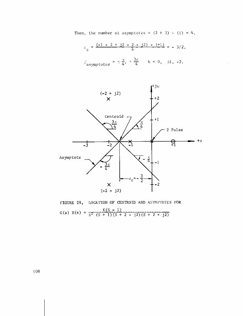
Then , the number of asymptotes = (2 + 3 ) - (1) = 4 .
- n. . 3n ,J -Pi, :- 4 k = 0, 21, - 2 . asymptotes
+ j w
(-2 + j 2 ) X -- +2
2 Po les
/ s fi - - - 1 Yl
t o t e
3
X - 2 (-2 - j2)
FIGURE 29. LOCATION O F CENTROID AND ASYMPTOTES FOR
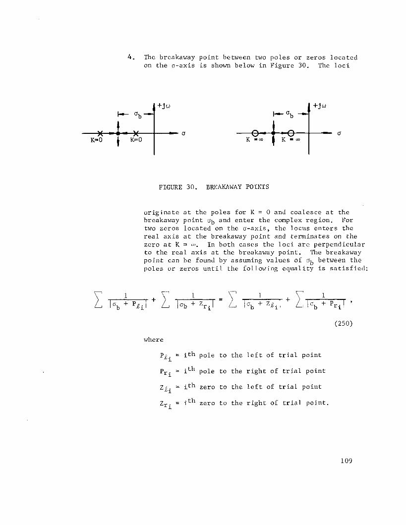
4 . The breakaway po in t between two poles or zeros loca ted on the a -ax is i s shown below i n F igure 30. The l o c i
FIGURE 30. BREAKAWAY POINTS
o r i g i n a t e a t the poles f o r K = 0 and coa lesce a t the breakaway po in t ab and e n t e r the complex reg ion . For two zeros loca ted on the a -ax is , the locus e n t e r s the r e a l a x i s a t the breakaway po in t and te rmina tes on the zero a t K = m. I n both cases the l o c i a r e perpendicular t o t he r e a l a x i s a t the breakaway poin t . The breakaway poin t can be found by assuming va lues of ab between the poles o r zeros u n t i l the following e q u a l i t y i s s a t i s f i e d :
where
P j i = i t h pole t o the l e f t of t r i a l po in t
Pri = ith pole t o the r i g h t of t r i a l po in t
Z j i = i t h zero t o t he l e f t of t r i a l po in t
zr = ith zero t o the r i g h t of t r i a l po in t .

5. The angle of depar ture i n which the locus leaves a complex pole o r e n t e r s a complex zero can be d e t e r - mined by adding up a l l the phase angle con t r ibu t ions t o t h e pole o r zero i n quest ion. Subt rac t ing t h i s sum from 180' g ives the requi red direc. t ion. For example, the angle of depar ture f o r the locus leaving pole P2 i n Figure 31 i s found from
FIGURE 31. ANGLE OF DEPARTURE
6. The preceding f i v e s t e p s provide enough information t o cons t ruc t only a po r t ion of the r o o t locus and t o determine the manner i n which the roo t locus w i l l behave. The remaining branches of the r o o t locus loca ted o f f the r e a l a x i s can be found by s t a r t i n g a t a breakaway po in t and success ive ly s e l e c t i n g t r i a l po in t s immediately above the breakaway po in t u n t i l the phase angle c r i t e r i o n i s s a t i s f i e d o r s t a r t i n g a t a pole loca ted of f the r e a l a x i s and s e l e c t i n g t r i a l po in ts along the tangent def ined by the angle of depar ture u n t i l the phase angle c r i t e r i o n i s s a t i s f i ed .
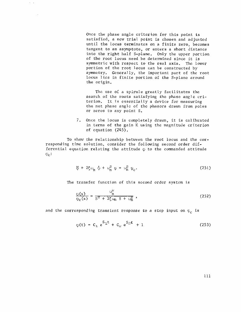
Once the phase angle c r i t e r i o n f o r t h i s po in t i s s a t i s f i e d , a new t r i a l po in t is chosen and ad jus t ed u n t i l t h e locus terminates on a f i n i t e zero , becomes tangent t o an asymptote, o r e n t e r s a s h o r t d i s t a n c e i n t o the r i g h t h a l f S-plane. Only the upper po r t ion of t he r o o t locus need be determined s ince i t i s symmetric wi th r e s p e c t t o the r e a l a x i s . The lower po r t ion of t he r o o t locus can be cons t ruc ted by symmetry. General ly , the important p a r t of the r o o t locus l i e s i n f i n i t e po r t ion of t he S-plane around the o r i g i n .
The use of a s p i r u l e g r e a t l y f a c i l i t a t e s the search of the r o o t s s a t i s f y i n g the phase ang le c r i - t e r i o n . It i s e s s e n t i a l l y a device f o r measuring the n e t phase angle of the phasors drawn from poles or zeros t o any po in t S.
7 . Once the locus i s completely drawn, it i s c a l i b r a t e d i n terms of the g a i n K using the magnitude c r i t e r i o n of equat ion ( 2 4 5 ) .
To show the r e l a t i o n s h i p between the r o o t locus and the cor- responding time s o l u t i o n , consider the following second order d i f - f e r e n t i a l equat ion r e l a t i n g the a t t i t u d e q t o the commanded a t t i t u d e
'PC:
The t r a n s f e r func t ion of t h i s second order system i s
and the corresponding t r a n s i e n t response t o a s t e p input on rqc i s
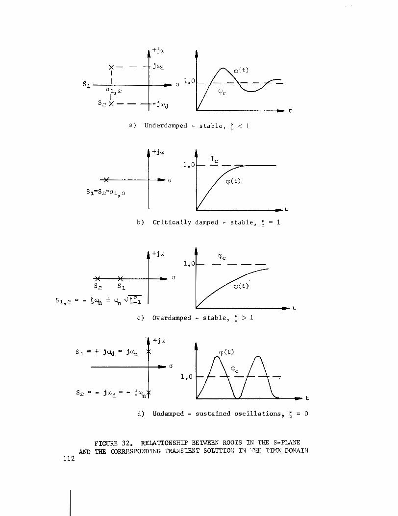
a ) Underdamped - stable, 5 <: 1
b) Critically damped - stable, 5 = 1
c) Overdamped - stable, 5 > 1
d) Undamped - sustained oscillations, 5 = 0
F I W 32. RELATIONSHIP BETWEEN ROOTS IN THE S-PLA2JE AND THE CORRESPOXDIXG W - S I E N T SOLUTIOR IN VIE TIME DOiviAIIJ
11 2
where the r o o t s obtained from the c h a r a c t e r i s t i c equat ion a r e ,
A p l o t of the r o o t s S l y S2 i n the S-plane and the corresponding t r a n s i e n t s o l u t i o n of cp f o r a s t e p input of cpc is shown i n Figure 32.
When the r o o t s S1, S2 a r e loca ted t o the l e f t of the jw-axis, the system i s s t a b l e , and the t r a n s i e n t p a r t of the response decays t o zero . When the r o o t s a r e l oca t ed on the jw-axis, the system conta ins no damp- ing , and sus t a ined o s c i l l a t i o n s r e s u l t . As the r o o t s move t o the r i g h t of t he jw-axis, the amplitude of the o s c i l l a t i o n s increases wi th time, and the system i s uns tab le . The above s ta tements a r e t r u e r ega rd l e s s of the order of the system. In the complex S-plane, ho r i zon ta l l i n e s repre- s e n t cons tan t damped frequency, wd; v e r t i c a l l i n e s r e p r e s e n t a cons tan t r a t e of decay, a; r a d i a l l i n e s through the o r i g i n r e p r e s e n t cons tan t damping r a t i o , 5 ; and c i r c l e s concent r ic about the o r i g i n r ep re sen t cons tan t n a t u r a l frequency, e.
D. Frequency-Response Method
The frequency-response metnod f o r the a n a l y s i s of feedback con- t r o l systems may be descr ibed a s the s tudy of system behavior w i th pure s inuso ida l inputs . It i s always assumed t h a t t h e s inuso ida l input has been appl ied f o r a long time so t h a t the t r a n s i e n t response has decayed and the s t e a d y - s t a t e condi t ion has been reached. I f the input t o a l i n e a r system i s s inuso ida l , then the dr iven response throughout the system must be s inuso ida l a l s o and of the same frequency, d i f f e r i n g only i n amplitude and phas'e. The frequency-response approach i s t he s tudy of the amplitude and phase angle of the response of a component o r a system a s a func t ion of the s inuso ida l frequency.
Using the frequency-response approach, the frequency and damping of the system cannot be obtained, bu t enough information can be obtained t o i n d i c a t e whether compensating networks a r e needed.
To o b t a i n t h e s t e a d y - s t a t e f r equency response l e t S assume v a l u e s equa l t o j w . The c o n t r o l r a t i o a s a f u n c t i o n of f r equency i s
For each v a l u e of f r equency , e q u a t i o n (253) y i e l d s a phasor q u a n t i t y whose magnitude is I C ( j o ) / ~ ( j w ) 1 and whose phase a n g l e i s t h e a n g l e between C(jw) and R(jw).
The p l o t s i n t h e f requency domain t h a t a r e used i n t h e a n a l y s i s of feedback c o n t r o l sys tems a r e of two c a t e g o r i e s . I n t h e f i r s t c a t e g o r y a r e t h e p l o t s of t h e magnitude of t h e o u t p u t - t o - i n p u t r a t i o and t h e cor- r e spond ing phase a n g l e v e r s u s f requency. These p l o t s may be made i n t h e r e c t a n g u l a r o r l o g a r i t h m i c c o o r d i n a t e s . The s t a n d a r d p rocedure i s t o p l o t 20 l o g [ ~ ( j w ) ~ ( j w ) 1 (magnitude i n d e c i b e l s ) and t h e phase a n g l e v e r s u s l o g w. T h i s p l o t i s o f t e n c a l l e d t h e Bode p l o t . The p l o t s i n t h i s f i r s t c a t e g o r y a r e p a r t i c u l a r l y u s e f u l i n r e p r e s e n t i n g t h e t r a n s f e r f u n c t i o n s o f i n d i v i d u a l components. I n t h e second c a t e g o r y a r e p o l a r p l o t s of t h e o u t p u t - i n p u t r a t i o , c a l l e d Nyquis t p l o t s , and p l o t s of 20 log I ~ ( j w ) H(jw) 1 v e r s u s phase , c a l l e d ~ i c h o l ' s p l o t s . The Nyquis t p l o t and N i c h o l ' s p l o t have f requency a s a runn ing parameter . These p l o t s a r e g e n e r a l l y used f o r t h e open-loop response . The p o l a r p l o t s when used f o r N y q u i s t ' s s t a b i l i t y c r i t e r i o n must b e drawn f o r f r e q u e n c i e s from -m t o +w
( cor respond ing t o t h e j w a x i s o f the S-p lane) .
I n a p p l y i n g t h e Nyquis t s t a b i l i t y t e s t , i t i s r e q u i r e d t h a t :
1. t h e sys tem be r e p r e s e n t e d by a s e t of l i n e a r d i f f e r e n t i a l e q u a t i o n s w i t h c o n s t a n t c o e f f i c i e n t s .
2. t h e o r d e r o f t h e denominator be equa l t o o r g r e a t e r than t h e o r d e r of t h e numerator of t h e open-loop t r a n s f e r f u n c t i o n G(s) H(s ) ; t h a t i s , t h e l i m G(s) H(s) -3 0
s o r a c o n s t a n t .
E . The Nyquis t S t a b i l i t y C r i t e r i o n
The Nyquis t s t a b i l i t y c r i t e r i o n r e l a t e s t h e number of z e r o s and p o l e s of t h e c h a r a c t e r i s t i c e q u a t i o n t h a t l i e i n t h e r i g h t - h a l f S-plane t o t h e p o l a r p l o t of t h e open-loop t r a n s f e r f u n c t i o n G(s) H(s ) . It can b e s t a t e d a s fo l lows :
Given any open-loop t r a n s f e r f u n c t i o n G(s ) H ( s ) , which i s the r a t i o of two polynomials i n t h e v a r i a b l e S, l e t S = jw.
The ampl i tude and phase p o l a r p l o t of G(jw) H(jw), a s t h e f requency is v a r i e d from -m t o +my e n c i r c l e s t h e ( -1 + jO) p o i n t N t imes . With coun te rc lockwise p o s i t i v e and c lock- wise n e g a t i v e ,
where PR e q u a l s t h e number o f p o l e s of G(s) H(s) i n t h e r i g h t - h a l f S-plane and ZR e q u a l s t h e number o f z e r o s of t h e c h a r a c t e r i s t i c e q u a t i o n i n t h e r i g h t - h a l f S-plane.
S i n c e a s t a b l e sys tem can have no z e r o s of t h e c h a r a c t e r i s t i c e q u a t i o n i n t h e r i g h t - h a l f S-plane, t h e n e t number of r o t a t i o n s N of G(s) H ( s ) abou t t h e (-1 + jO) p o i n t must be coun te rc lockwise and equa l t o t h e number of p o l e s t h a t l i e i n t h e r i g h t - h a l f S-plane.
I f G(s) H(s) e x p e r i e n c e s a n e t c lockwise r o t a t i o n a b o u t t h e (-1 + j O ) p o i n t , ZR > PR and t h e sys tem i s u n s t a b l e . I f t h e r e a r e z e r o n e t r o t a t i o n s , t h e n ZR = PR and t h e sys tem may o r may n o t be s t a b l e , depending on whether PR = 0 o r PR > 0, r e s p e c t i v e l y . I f PR > 0 , t h e number of p o l e s i n t h e r i g h t - h a l f S-plane can be determined by a p p l y i n g Routh 's c r i t e r i o n t o DID2 (denominator of open-loop t r a n s f e r f u n c t i o n i n e q u a t i o n (227).
I f Nyquis t p l o t r e p r e s e n t i n g a system is complicated, i t is sometimes d i f f i c u l t t o determine i f t h e curve e n c i r c l e s t h e (-1 + jO) p o i n t , and , i f i t does , how many e n c i r c l e m e n t s i t makes. To de te rmine i f a sys tem i s s t a b l e o r u n s t a b l e , t r a c e t h e curve i n t h e d i r e c t i o n of i n c r e a s i n g f requency. I f t h e (-1 + jO) p o i n t is always t o t h e l e f t of t h e curve , t h e sys tem i s s t a b l e .
I f t h e open-loop t r a n s f e r f u n c t i o n were t o pass through t h e (-1 + jO) p o i n t , a c o n d i t i o n of s u s t a i n e d o s c i l l a t i o n s would e x i s t , r e p r e s e n t i n g a m a r g i n a l l y s t a b l e system. The c l o s e r the open-loop f requency response c h a r a c t e r i s t i c curve comes t o p a s s i n g through t h e ( -1 + jO) p o i n t t h e c l o s e r t h e c losed- loop system i s t o being u n s t a b l e . The degree of s t a b i l i t y of the system i s measured by two f a c t o r s - g a i n margin and phase margin.
Gain margin i s t h e measure o f t h e f a c t o r by which t h e g a i n of a sys tem would have t o be i n c r e a s e d t o make i t m a r g i n a l l y s t a b l e . Phase margin , em, i s a measure of how much a d d i t i o n a l phase l a g is r e q u i r e d t o make a sys tem m a r g i n a l l y s t a b l e i f t h e g a i n i s unchanged. A minimum of 6 db g a i n margin and 30 degrees phase margin i s cons idered t o be a c c e p t a b l e margins f o r sys tem s t a b i l i t y i n c o n t r o l sys tem d e s i g n . A minimum of 6 db g a i n margin and 30 degrees phase margin is cons idered t o be a c c e p t a b l e margins f o r sys tem s t a b i l i t y i n c o n t r o l sys tem d e s i g n .
On t h e Nyquis t p l o t , t h e g a i n margin i s t h e r e c i p r o c a l of t h e v a l u e of G(jw) H(jw) a t phase c r o s s o v e r ( t h e p o i n t a t which t h e f requency response curve c r o s s e s t h e -180" a x i s ) . The phase margin i s 180" p l u s t h e phase a n g l e a t g a i n c r o s s o v e r ( t h e p o i n t on t h e p l o t a t which t h e magni tude i s u n i t y ) .
Using t h e ~ i c l l o l ' s p l o t ( l o g magnitude v e r s u s phase a n g l e ) , a sys tem i s s t a b l e i f t h e Gdb, -180" p o i n t i s always t o t h e r i g h t when t r a c i n g t h e curve i n the d i r e c t i o n of i n c r e a s i n g f requcncy. Gain margin and phase margin can be determined q u i t e r e a d i l y from t h e N i c h o l ' s p l o t . The g a i n margin ( i n d e c i b e l s ) i s measured where t h e curve c r o s s e s t h e -180" a x i s . The phase margin i s 180" p l u s t h e phase a n g l e a t t h e p o i n t where the curve c r o s s e s the 0-db a x i s . Q u i t e o f t e n t h e magnitude of t h e response ( i n d e c i b e l s ) i s p l o t t e d v e r s u s phase a n g l e p l u s 180". For t h i s p l o t t h e o r i g i n i s t h e 0-db, 0 phase margin p o i n t i n s t e a d of t h e 0-db, -180" p o i n t . This p l o t e n a b l e s one t o r e a d phase margins a t a g l a n c e .
On t h e Bode p l o t t h e g a i n margin i s measured i n d e c i b e l s on t h e l o g magnitude curve where t h e p h a s e - s h i f t cu rve c r o s s e s the -180" l i n e . Phase margin i s measured on t h e p h a s e - s h i f t cu rve a t t h e f r e - quency where t h e log-magnitude curve c r o s s e s t h e 0-db l i n e .
The e a s i e s t s t e p i n a d j u s t i n g f o r a s a t i s f a c t o r y sys tem response i s t o a d j u s t t h e g a i n . I f s a t i s f a c t o r y response cannot be ach ieved by g a i n ad jus tment a l o n e , then compensating t echn iques must be used.
A r o o t l o c u s p l o t , Bode p l o t s , Nyquist p l o t s , and N i c h o l l s p l o t s have been drawn f o r a sys tem of e q u a t i o n s t o i l l u s t r a t e many of t h e t h i n g s t h a t have been d i s c u s s e d . The fo l lowing s e t of e q u a t i o n s , c o n s i d e r i n g o n l y one bending mode, was used:
By s u b s t i t u t i n g e q u a t i o n s (255) , (256) , and (257) i n t h e o t h e r e q u a t i o n s , t h e system e q u a t i o n s a r e reduced t o s i x e q u a t i o n s i n s i x unknowns.
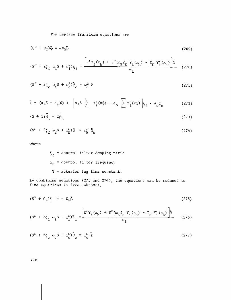
The Laplace transform equat ions a r e
where
S c = con t ro l f i l t e r damping r a t i o
wC = con t ro l f i l t e r frequency
T = a c t u a t o r lag time cons tan t .
By combining equat ions (273 and 2 7 4 ) , the equations can be reduced t o f i v e equat ions i n f i v e unknowns.
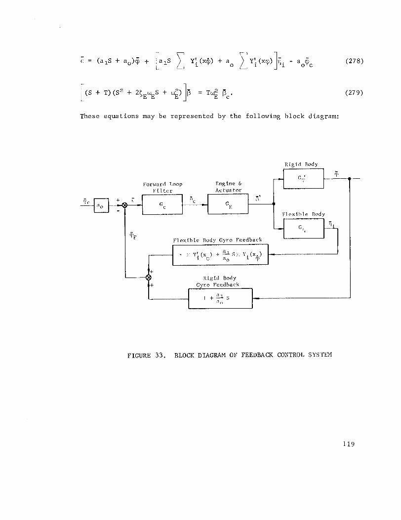
These equat ions may be represented by the following block diagram:
R i g i d Rody
Forward T,oop 1:i l t c r
Engine & A c t u a t o r
F l e x i b l e Rody Gyro Feedback
R i g i d Body Gyro Feedback
1
P 1 t 3 s " 0
FIGURE 33. BLOCK DIAGRAM OF FEEDBACK CONTROL SYSTEM
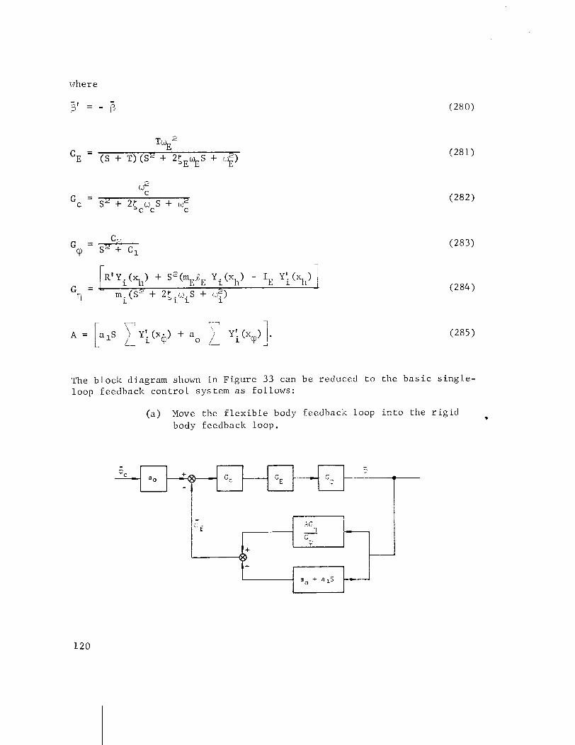
where
- P I = - @
The b l o c k diagram shown i n F i g u r e 33 can be reduced t o t h e b a s i c s i n g l e - loop feedback c o n t r o l sys tem a s fo l lows :
( a ) Move the f l e x i b l e body feedback loop i n t o t h e r i g i d body feedback loop.
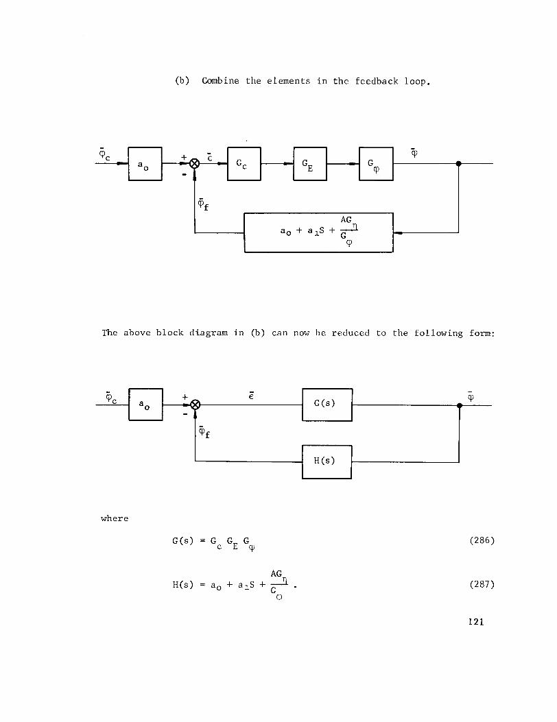
(b) Combine t h e e lements i n t h e feedback loop .
The above b lock diagram i n (b) can now be reduced t o t h e fo l lowing form:
where
- 'PC -
a,
- + E
-
@ £
- -
c
AG a, + alS + 3
G cP
-
GE - G
'P
- 'P
w

Open-Loop Transfer Function
where
Closed-Loop Transfer Function
- cP
- = G (s) 0 1 + G(s) H(s)
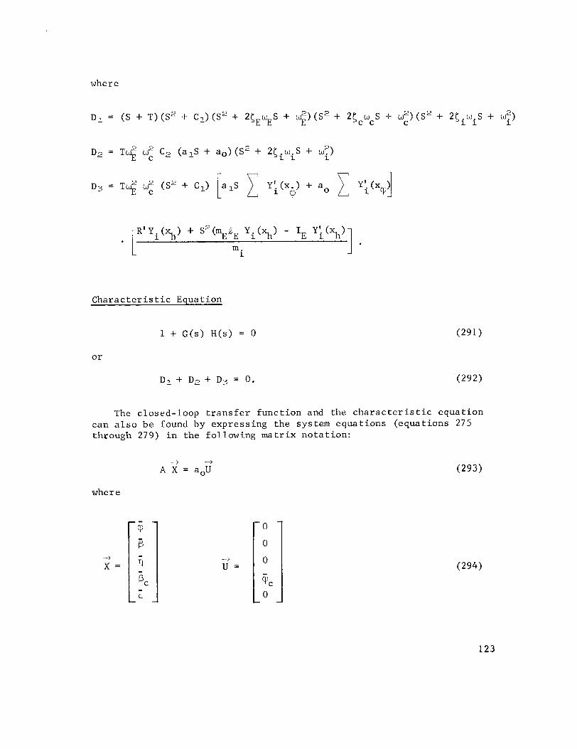
C h a r a c t e r i s t i c Equat ion
The c losed- loop t r a n s f e r f u n c t i o n and the c h a r a c t e r i s t i c e q u a t i o n can a l s o be found by e x p r e s s i n g t h e sys tem e q u a t i o n s ( e q u a t i o n s 275 through 279) i n t h e fo l lowing m a t r i x n o t a t i o n :
where

The closed-loop t r a n s f e r func t ion (P/V may be obtained b y s e t t i n g C
-3
where A: i s the mat r ix wi th aoU rep lac ing the f i r s t column ( the column desc r ib ing t h e con t r ibu t ion of (P t o the homogeneous equa t ion) .
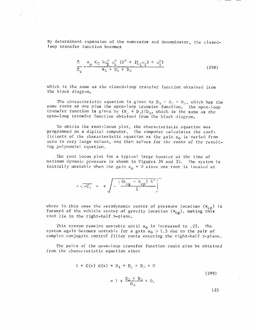
By d e t e r m i n a n t expans ion of t h e numerator and denominator , the c l o s e d - loop t r a n s f e r f u n c t i o n becomes
which i s t h e same a s t h e c l o s e d - l o o p t r a n s f e r f u n c t i o n o b t a i n e d from t h e b l o c k diagram.
The c h a r a c t e r i s t i c e q u a t i o n is g i v e n by Dl -l- DL + D;, which has t h e same r o o t s a s one p l u s the open-loop t r a n s f e r f u n c t i o n . The open-loop t r a n s f e r f u n c t i o n is g i v e n by (D, + D ~ ) / D ~ , which is t h e same a s t h e open-loop t r a n s f e r f u n c t i o n o b t a i n e d from the b lock diagram.
To o b t a i n t h e r o o t - l o c u s p l o t , t h e c h a r a c t e r i s t i c e q u a t i o n was programmed on a d i g i t a l computer. The computer c a l c u l a t e s t h e c o e f - f i c i e n t s of t h e c h a r a c t e r i s t i c e q u a t i o n a s the g a i n a, i s v a r i e d from z e r o t o v e r y l a r g e v a l u e s , and then s o l v e s f o r the r o o t s o f t h e r e s u l t - ing polynomial e q u a t i o n .
The r o o t l o c u s p l o t f o r a t y p i c a l l a r g e b o o s t e r a t the t ime of maximum dynamic p r e s s u r e is shown i n F i g u r e s 34 and 35. The sys tem i s i n i t i a l l y u n s t a b l e when the g a i n a. = 0 s i n c e one r o o t i s l o c a t e d a t
where i n t h i s c a s e t h e aerodynamic c e n t e r o f p r e s s u r e l o c a t i o n (x,.?) is forward of t h e v e h i c l e c e n t e r of g r a v i t y l o c a t i o n ( x c g ) , making t h ~ s r o o t l i e i n t h e r i g h t - h a l f S-plane.
Th i s sys tem remains u n s t a b l e u n t i l a. i s i n c r e a s e d t o . 25 . The sys tem a g a i n becomes u n s t a b l e f o r a g a i n a. > 1 . 5 due t o t h e p a i r of complex c o n j u g a t e c o n t r o l f i l t e r r o o t s e n t e r i n g t h e r i g h t - h a l f S-plane.
The p o l e s of t h e open-loop t r a n s f e r f u n c t i o n could a l s o be o b t a i n e d from t h e c h a r a c t e r i s t i c e q u a t i o n s i n c e
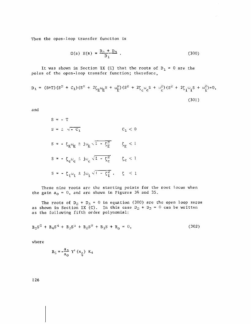
Then the open-loop t r a n s f e r func t ion i s
It was shown i n Sect ion I X (C) t h a t the roo t s of Dl = 0 a r e the poles of the open-loop t r a n s f e r func t ion; t he re fo re ,
oI = (S+T) (s2 + C1) ( s2 + 2CE%s + $) ( s2 + 2cCwcs + w2) (s2 + 2Ciwis + w:)=o, C
(301)
and
These nine r o o t s a r e the s t a r t i n g poin ts f o r the r o o t locus when the ga in a. = 0, and a r e shown i n Figures 34 and 35.
The r o o t s of D, + D3 = 0 i n equat ion (300) a r e the open loop zeros a s shown i n Sec t ion I X ( C ) . I n t h i s case D2 + D3 = 0 can be w r i t t e n a s the following f i f t h order polynomial:
where

For t y p i c a l va lues of the cons tan ts i n the Bi c o e f f i c i e n t s , equat ion (302) becomes
and the f i v e r o o t s a r e
These a r e the po in t s on which the r o o t locus te rmina tes a s the ga in approaches i n f i n i t y . They a r e shown a s small c i r c l e s i n F igures 34 and 35. Since t h e r e a r e n ine open-loop poles and f i v e open-loop zeros, four of the l o c i must te rmina te on zeros loca ted a t S = a.
To i l l u s t r a t e Routh's c r i t e r i o n , the c h a r a c t e r i s t i c equat ions f o r an a. of 1.4 and 1.5 were s e t up i n the Routhian a r r a y (Table 4) . For an a, of 1.4, a l l s i g n s i n t h e f i r s t column a r e p o s i t i v e , i n d i c a t i n g a s t a b l e system; f o r an a. of 1.5, t he re a r e two s i g n changes i n the f i r s t column, i n d i c a t i n g two r o o t s i n t he r i g h t - h a l f S-plane and hence, an uns t ab le system.
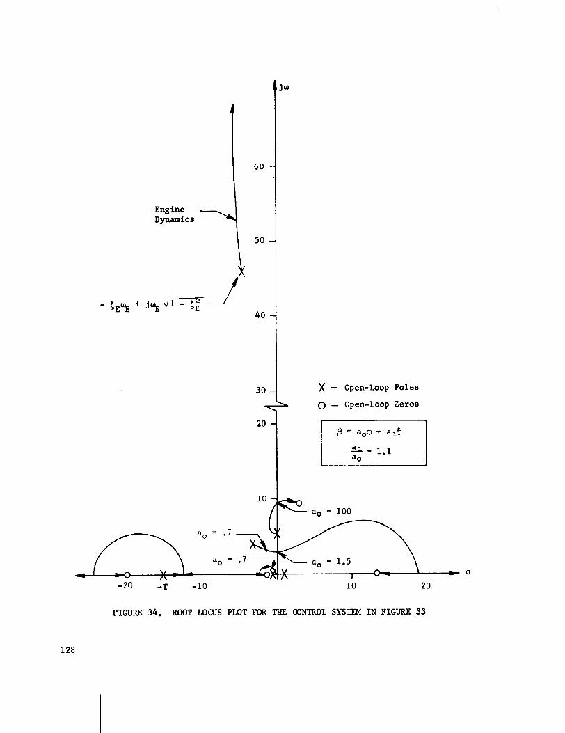
)( - Open-Loop Poles 0 - Open-Loop Zeroe
FIGURE 34. ROOT LOCUS PLOT FOR THE CONTROL SYSTEM IN FIGURE 33
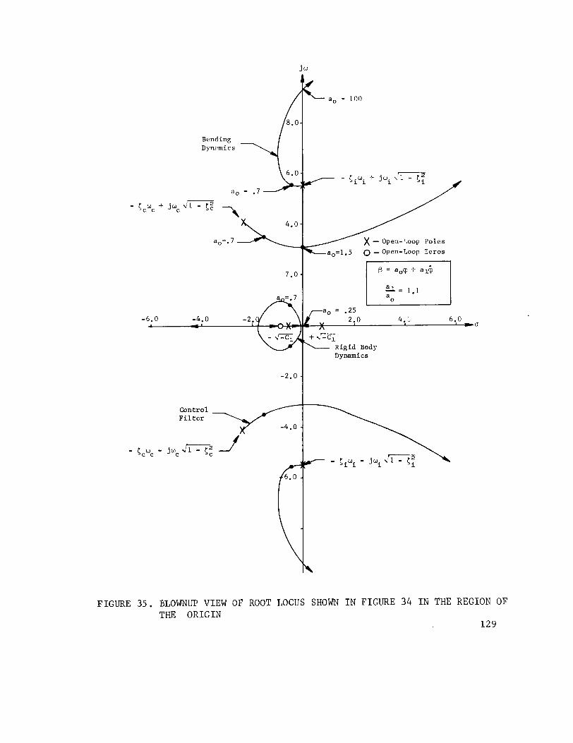
a, = 100
Bending Dynomics
% l - c: 3
ao=l. 5 0 - Open-Loop Zeros
-6.0 -4.0 -2 . 4 . - 1 -
Dynamics
FIGURE 35. ELOWNUP VIEW O F ROOT LOCUS SHOWN I N F I G U R E 34 I N THE R E G I O N OF THE O R I G I N
1 2 9
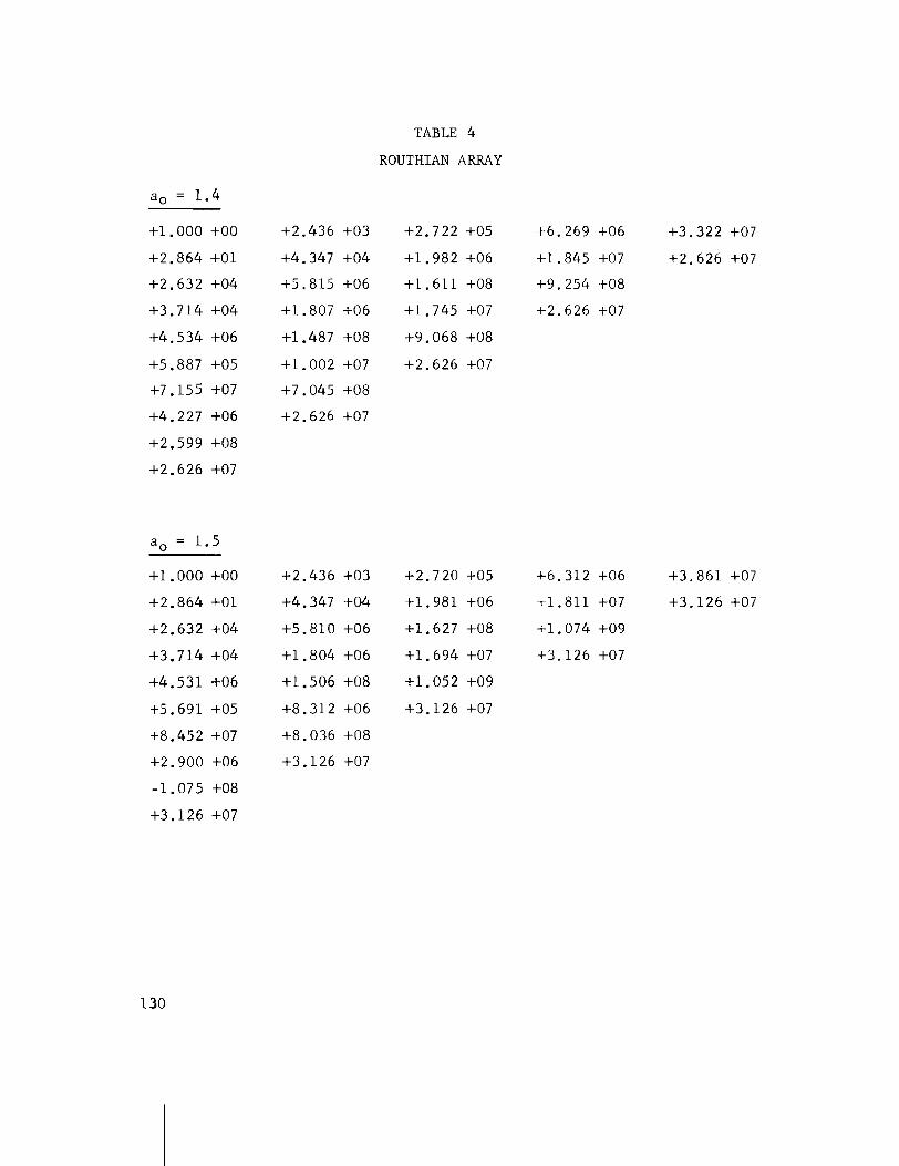
TABLE 4
ROUTHIAN ARRAY

For the Nyquist p l o t s (Figures 36 A-C), ~ i c h o l ' s p l o t s (Fig- u re s 37 A-C), and Bode p l o t s (Figures 38 A - C ) , t h r ee d i f f e r e n t ga ins were used: .2, .7, and 1.5. Gains of . 2 and 1 . 5 r ep re sen t uns tab le systems; ga ins of .7 r ep re sen t a s t a b l e system. Gain and phase margins a r e shown on t h e Bode p l o t s , Nyquist p l o t s , and Nichol 's p l o t s where i t i s poss ib l e t o i n d i c a t e these . The system considered i s a con- d i t i o n a l l y s t a b l e system; t h a t i s , i t can be made uns tab le by increas ing o r decreasing the ga in . Since t h i s i s t r u e , t h e r e a r e two ga in margins t o ,consider - a f a c t o r by which the g a i n i s increased and a f a c t o r by which the ga in i s de&eased. On the Bode p l o t s and Nichol ' s p l o t s , a p o s i t i v e o r nega t ive s ign has been used t o i n d i c a t e whether the ga in should be increased o r decreased.
FIGURE 36A. NYQUIST PLOT, f3 = .2c$ + .22@
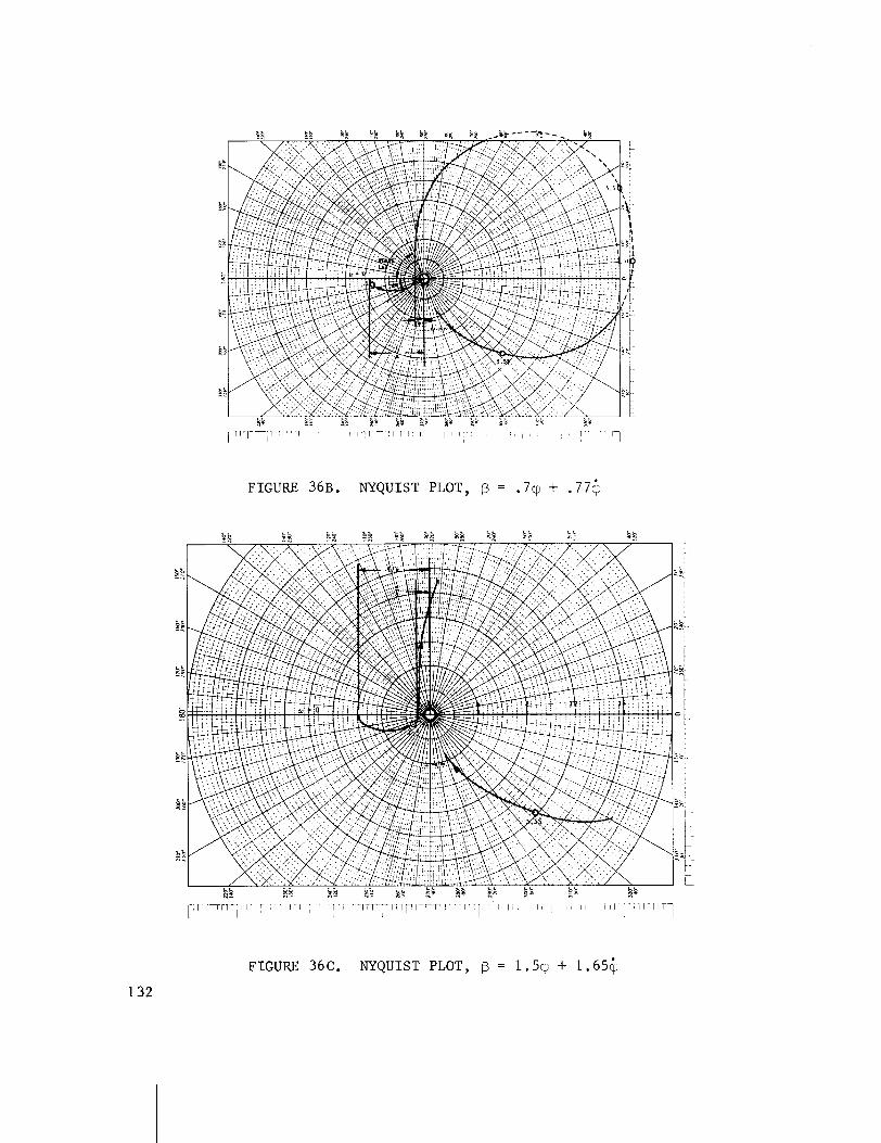
I
FIGURE 36B. NYQUIST PLOT, P = .79 + . 7 7 6
1 l l T n l T I I 1 I I l rl-I I r l r ' l T I TI 1 1 1 1 ' I
FIGURE 36C. NYQUIST PLOT, B = 1.59 + 1.654
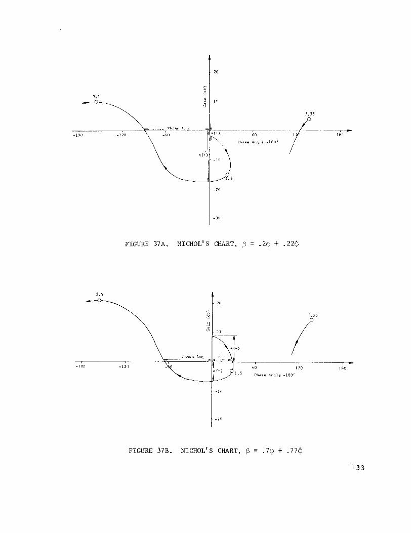
FIGURE 37A. NICHOL'S CHART, 13 = .2q + .22c
FIGURE 37B. NICHOL' s CHART, f3 = .7cp + .77$

F I G U R E 3 7 C . N I C H O L ' S CHART, !3 = 1 . 5 ~ + 1.65@
F I G U R E 3 8 A . BODE PLOT, f3 = . 2 q + .22@
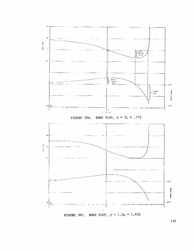
FIGURE 38B. BODE PLOT, f3 = 7cp + .77+
, I '
FIGURE 38C. BODE PLOT, @ = 1 . 5 ~ + 1.654
X. ADAPTIVE CONTROL
As a b o o s t e r v e h i c l e moves on i ts t r a j e c t o r y from the dense atmosphere a t low a l t i t u d e s t o the r a r e atmosphere a t h i g h a l t i t u d e s , extreme changes occur i n t h e aerodynamic parameters and mass d i s t r i b u t i o n . A f i x e d s e t o f g a i n s and compensation t ime c o n s t a n t s may be i n c a p a b l e of p r o v i d i n g s a t i s - f a c t o r y performance th roughout t h e t r a j e c t o r y . I n s t e a d , a g a i n s c h e d u l i n g p rocedure i s r e q u i r e d i n the c o n t r o l e lements a s the su r round ing condi- t i o n s change. Th i s procedure i s n o t p a r t i c u l a r l y a t t r a c t i v e f o r s e v e r a l r e a s o n s .
F i r s t , a c c u r a t e informa t i o n i s r e q u i r e d abou t t h e aerodynamic and s t r u c t u r a l c h a r a c t e r i s t i c s of t h e v e h i c l e and i t s environment. Second, t h e r e is t h e need t o measure a i r d a t a . Th i rd , t h e e s t a b l i s h m e n t of t h e g a i n s c h e d u l i n g i s a long d i f f i c u l t p r o c e s s .
The a t t r a c t i v e f e a t u r e s of a s e l f - a d a p t i v e c o n t r o l s y s tem a r e t h a t i t e l i m i n a t e s t h e need f o r a c c u r a t e i n f o r m a t i o n abou t t h e c o n t r o l l e d sys tem and i t a d j u s t s t h e c o n t r o l parameters on the b a s i s of t h e amount of d e v i a t i o n e x i s t i n g between t h e a c t u a l and d e s i r e d o u t p u t r e sponse .
Var ious types of s e l f - a d a p t i v e c o n t r o l systems have been developed i n r e c e n t y e a r s . N o a t t e m p t is made t o d i s c u s s t h e v a r i o u s types of s e l f - a d a p t i v e c o n t r o l sys tems , b u t on ly a d e s c r i p t i o n of one of t h e most prominent sys tems which is a p p l i c a b l e t o the c o n t r o l of ae rospace v e h i c l e s i s p r e s e n t e d .
The fo l lowing a d a p t i v e c o n t r o l sys tem was developed by Minneapol is - Honeywell [ 3 ] f o r a l a r g e , h i g h l y e l a s t i c b o o s t e r v e h i c l e . The two ou t - s t a n d i n g v i r t u e s of t h i s sys tem a r e i t s i n h e r e n t a b i l i t y t o s e l f - a d j u s t i t s c o n t r o l g a i n t o compensate f o r changes i n c o n t r o l moment and i t s t o l e r a n c e t o v a r i a t i o n s i n aerodynamic c h a r a c t e r i s t i c s and s t r u c t u r a 1 mode shapes and f r e q u e n c i e s .

Model Concept - - - - - - - - I I
Model
Adaptive Gain Changer I- - - - - - - - - - - - -
1 I - -1
Dual-Rate-Gyro Blender - - - - - - - - - - - - - - -1
I
I I I
- Blender I
I ( I
I I A£ t
Rate I
I -
I Gyro 7
I 1 I - - - - - - - - - - - - - - - - - -
Forward Loop
Compensation
Attitude Gyro
I I Ga in
FIGURE 39. COMPLETE ADAPTIVE SYSTEM CONCEPT
- I + - 1 -
I I
Vehicle E I
I Servo
% I Changer
_B+f,
- I I I
I
i
I I L , - - - - - - - - - - - -
A. Model Concept
The model concept u t i l i z e s a s imple l a g f i l t e r ( t h e model) t o shape t h e a t t i t u d e e r r o r s i g n a l which s e r v e s a s a command t o a r e l a t i v e l y f a s t a t t i t u d e r a t e i n n e r loop. By making t h e band wid th of t h e a t t i t u d e r a t e loop a t l e a s t t h r e e t imes l a r g e r than the bandwidth o f the model, t h e o v e r - a l l r e sponse between a t t i t u d e e r r o r ( a t t i t u d e r a t e command) and v e h i c l e a t t i t u d e r a t e is e s s e n t i a l l y e s t a b l i s h e d by t h e model.
The b lock diagram shown i n F igure 40 can be reduced t o t h e s i m p l i f i e d b lock diagram a s shown i n F igure 41.
The c losed- loop t r a n s f e r f u n c t i o n i s ob ta incd by s o l v i n g the fo l lowing system of e q u a t i o n s o b t a i n e d from the block diagram i n F ig - u r e 41 f o r t h e r a t i o @/@,.
The c losed- loop t r a n s f e r f u n c t i o n then i s
I f t h e c o n t r o l g a i n Kc i n e q u a t i o n (308) i s i n c r e a s e d t o l a r g e v a l u e s t h e t r a n s f e r f u n c t i o n between a n a t t i t u d e change and an a t t i t u d e command approaches a f i x e d second o r d e r c h a r a c t e r i s t i c :

FIGURE 40. NORMAL SYSTEM CONFIGURATION
FIGURE 41. SIMPLIFIED BLOCK DIAGRAM OF ATTITUDE CONTROL SYSTEM
1 c2s ls+cy(c$ ,c ,K, ) I
s3+ + s4c1s- * - CPc 8
-
F i x e d M o d e l And A t t i t u d e G a i n
K Q
T$+l
J
1 - S
V a r i a b l e * R i g i d Body C o n t r o l Transfer
G a i n Function
- 0
.
+ E -@- - Kc
-B
Here i t can be seen t h a t t h e d e s i r e d f requency
and damping
a r e c o n t r o l l e d e x c l u s i v e l y by t h e model time l a g T,,, and a t t i t u d e g a i n % i f t h e c o n t r o l g a i n Kc is main ta ined a t a s u f f i c i e n t l y h igh v a l u e .
The a c t i o n of t h e c o n t r o l sys tem i n f o r c i n g t h e v e h i c l e toward t h e d e s i r e d f requency and damping i s i l l u s t r a t e d by c o n s i d e r i n g t h e l o c u s of t h e c losed- loop p o l e s of the sys tem a s a f u n c t i o n of changes i n g a i n Kc a s shown i n F i g u r e 42. It i s e v i d e n t from t h i s p l o t t h a t i n c r e a s i n g c o n t r o l g a i n f o r c e s t h e u n s t a b l e v e h i c l e p o l e s toward t h e p a i r o f ze ros e s t a b l i s h e d by t h e combination of r a t e feedback p l u s t h e f i x e d model t ime c o n s t a n t and f i x e d a t t i t u d e g a i n . These z e r o s a r e e s t a b l i s h e d a t t h e d e s i r e d n a t u r a l f requency and damping r a t i o by choosing a p p r o p r i a t e v a l u e s of Tm and $ f o r Kc + m . For t h i s case t h e f requency and damping was chosen t o be
Frequency: 1 .87 =
Damp ing : 1
.68 = - & 2 TmKp
then ,
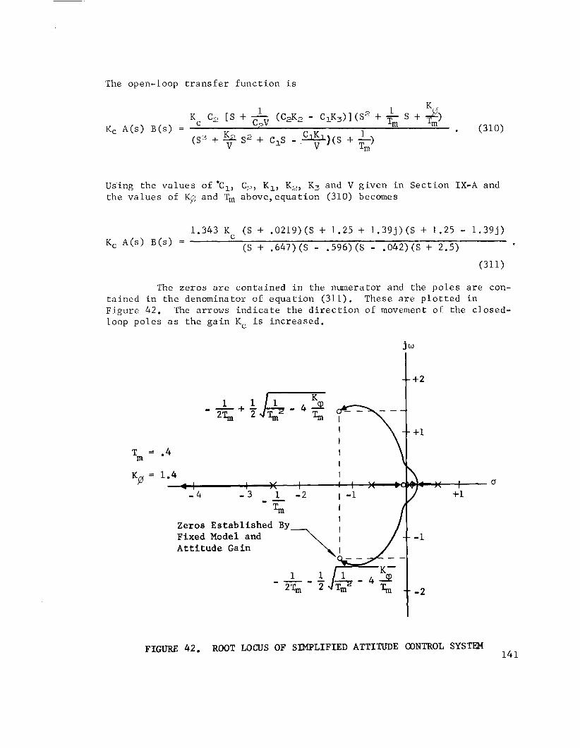
The open-loop t r a n s f e r f u n c t i o n i s
Using t h e v a l u e s of ' c ~ , C2, K1, K2, Kj and V g i v e n i n S e c t i o n IX-A and t h e v a l u e s of KG and Tm a b o v e , e q u a t i o n (310) becomes
The z e r o s a r e con ta ined i n t h e numerator and the p o l e s a r e con- t a i n e d i n t h e denominator of e q u a t i o n (311). These a r e p l o t t e d i n F igure 42. The arrows i n d i c a t e t h e d i r e c t i o n of movement o f t h e c losed- loop p o l e s a s t h e g a i n Kc i s i n c r e a s e d .
Tm = '4
Kg = 1.4
- 1 I I 0 - I \ - 4 - 3 1 - 2 +1
Zeros Established By Fixed Model and Attitude Gain
FIGURE 42. ROOT LOCUS OF SIMPLIFIED ATTITUTJE CONTROL SYSTEM 141

I f the con t ro l ga in Kc can be made s u f f i c i e n t l y l a r g e , the b a s i c system i s h igh ly t o l e r a n t t o changes i n veh ic l e c h a r a c t e r i s t i c s a s can be seen from equat ion (309) where the r i g i d body t r a n s f e r func t ion com- p l e t e l y drops ou t . It becomes inc reas ing ly d i f f i c u l t though t o achieve the necessary h igh inner loop ga in a s a d d i t i o n a l con t ro l l ags (low f r e - quency s t r u c t u r a l bending modes) a r e introduced i n the con t ro l loop, un less some means of c o n t r o l l i n g the loop ga in i s employed.
B. Adaptive Gain Control
I f the v e h i c l e aerodynamic and s t r u c t u r a l da ta a r e known accu ra t e ly and i f t h e r e i s adequate ~ e p a r a t i o n between the des i r ed r i g i d body frequency and the lowest s t r u c t u r a l mode, adequate con t ro l can be achieved by scheduling con t ro l ga in i n an open loop manner, e .g changing g a i n a s a func t ion of time. Basic t o t h i s approach i s the requirement f o r adequate rigid-body and s t r u c t u r a l mode ga in ntargins. Current t rends i n the design of boos ter conf igura t ions make t h i s i nc reas ing ly d i f f i c u l t t o accomplish.
With adapt ive ga in con t ro l , s p e c i f i e d ga in margins a r e unnecessary because the g a i n l e v e l e s t ab l i shed in the system i s based on measured i n f l i g h t cha rac t e r i s t i c s r a t h e r than predic ted va lues . The adap t ive g a i n changer opera tes t o maintain the inner loop ga in e i t h e r a t i t s maximum s t a b l e value o r a t some f ixed percentage depend- ing on the mechanization employed.
The r a t e loop s t a b i l i t y i s discussed f i r s t t o e s t a b l i s h the b a s i c premise on which tfie ga in changer concepts a r e founded. For s i m p l i c i t y , only the r i g i d body w i l l be considered and the r e s u l t s a r e app l i cab le i n p r i n c i p l e even when a l l system dynamics a r e included.
The s imp l i f i ed r a t e loop block diagram wi th un i ty feedback i s shown below.
FIGURE 4 3 . SIMPLIFIED BLOCK DIAGRAM OF RATE LOOP
- @-
Var i ab 1 e Propor t iona l Rigid Vehicle Forward and I n t e g r a l Transfer Function Loop Gain Gains
CpS S" + ds + C1
K S + K i
S
T
Kc
- -
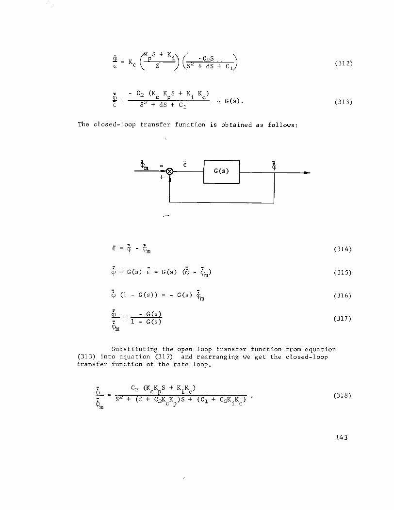
The c losed- loop t r a n s f e r f u n c t i o n is o b t a i n e d a s fo l lows :
S u b s t i t u t i n g t h e open loop t r a n s f e r f u n c t i o n from e q u a t i o n (313) i n t o e q u a t i o n (317) and r e a r r a n g i n g we g e t t h e c losed- loop t r a n s f e r f u n c t i o n of t h e r a t e loop.
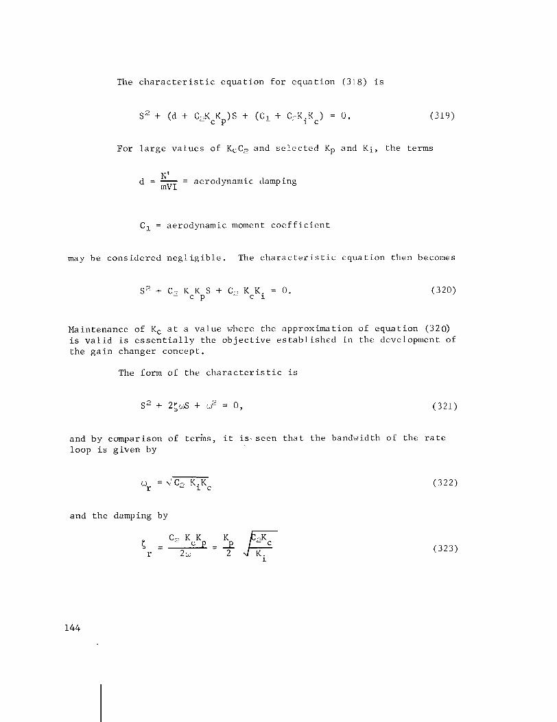
The c h a r a c t e r i s t i c e q u a t i o n f o r e q u a t i o n (318) i s
For l a r g e v a l u e s of KcC2 and s e l e c t e d Kp and K i , t h e terms
d = - = N' aerodynamic damping m V I
C1 = aerodynamic moment c o e f f i c i e n t
may be c o n s i d e r e d n e g l i g i b l e . The c h a r a c t e r i s t i c e q u a t i o n then becomes
Maintenance of Kc a t a v a l u e where t h e approx imat ion of e q u a t i o n (320) i s v a l i d i s e s s e n t i a l l y t h e o b j e c t i v e e s t a b l i s h e d i n t h e development of t h e g a i n changer concept .
The form o f t h e c h a r a c t e r i s t i c i s
and by comparison of terms, i t i s - seen t h a t t h e bandwidth of t h e r a t e loop i s g i v e n by
and t h e damping by

where
C, = c o n t r o l moment c o e f f i c i e n t
Kc = forward loop g a i n
Kp = forward p r o p o r t i o n a l g a i n
Ki = forward i n t e g r a l g a i n .
Except f o r t h e term C,, t h e r a t e loop dynamics dominate a l l i n h e r e n t c h a r a c t e r i s t i c s of t h e v e h i c l e . By r e f e r r i n g t o e q u a t i o n (320), i t is e v i d e n t t h a t comple te ly uniform c h a r a c t e r i s t i c s a r e main ta ined by an i n v e r s e v a r i a t i o n of loop g a i n Kc w i t h C,.
Loop Gain Kc Opera t ing a t C r i t i c a l Value
Opera t ing t h e loop g a i n Kc a t i t s c r i t i c a l v a l u e f o r c e s t h e s y s tem i n t o o s c i l l a t o r y mot ion ( i . e . , t h e o p e r a t i n g p o l e s move t o the j ~ a x i s ) . The o s c i l l a t i o n deve lops i n t o a l i m i t c y c l e hav ing a con- s t a n t s m a l l ampl i tude a t a l l f l i g h t c o n d i t i o n s . From e q u a t i o n (322) i t i s s e e n t h a t m a i n t a i n i n g Kc a t a maximum v a l u e p r o v i d e s t h e maximum r a t e loop bandwidth and maximum r i g i d body s t a b i l i t y margin . The l i m i t c y c l e f r equency i s determined by t h e f requency of t h e l e a s t s t a b l e r o o t l o c u s c r o s s i n g i n t o t h e r i g h t h a l f p l a n e . On most l a r g e v e h i c l e s the f i r s t bending mode w i l l e s t a b l i s h t h e p r a c t i c a l l i m i t t o t h e bandwidth of t h e a t t i t u d e r a t e loop . The l i m i t c y c l e t o o p e r a t e t h e g a i n changer w i l l t hen be c l o s e t o t h e f i r s t bending mode f requency.
For a g i v e n s e n s o r l o c a t i o n and c o n t r o l dynamics, a g a i n cor - r i d o r w i l l be a v a i l a b l e s i m i l a r t o t h a t shown i n F i g u r e 44. The w i d t h of t h i s c o r r i d o r w i l l depend on the compensating networks and t h e loca - t i o n of s e n s o r s . The upper g a i n l i m i t , which r e p r e s e n t s t h e h i g h ' f r e - quency s t a b i l i t y boundary, w i l l be p r i m a r i l y determined by t h e a t t i t u d e r a t e loop dynamics. The lower g a i n l i m i t , which r e p r e s e n t s the low f requency s t a b i l i t y boundary, w i l l be determined by b o t h t h e i n n e r loop ( a t t i t u d e r a t e ) and o u t e r loop ( a t t i t u d e and l a t e r a l a c c e l e r a t i o n ) dynamics.
As t h e bending mode f r e q u e n c i e s d e c r e a s e , t h e upper g a i n l i m i t moves down; a s the degree of s t a t i c i n s t a b i l i t y i n c r e a s e s , t h e lower g a i n l i m i t moves up. The use of t h e a u t o m a t i c g a i n changer w i l l keep t h e s y s - tem o p e r a t i n g a l o n g the upper g a i n boundary and w i l l p rov ide maximum r i g i d body s t a b i l i t y margin. The opera t i o n of the g a i n changer is d e s c r i b e d below w i t h r e f e r e n c e t o t h e b l o c k diagram i n F i g u r e 45 and r o o t l o c u s i n F igure 46.
I n p u t t o t h e u n i t i s a p p l i e d t o two f i l t e r s from t h e s i g n a l r e p r e s e n t i n g engine d e f l e c t i o n . The down l o g i c f i l t e r is a band pass which p a s s e s f r e q u e n c i e s n e a r the chosen l i m i t c y c l e f r equency . The up l o g i c f i l t e r p a s s e s f r e q u e n c i e s n e a r t h e r i g i d body f requency .
145
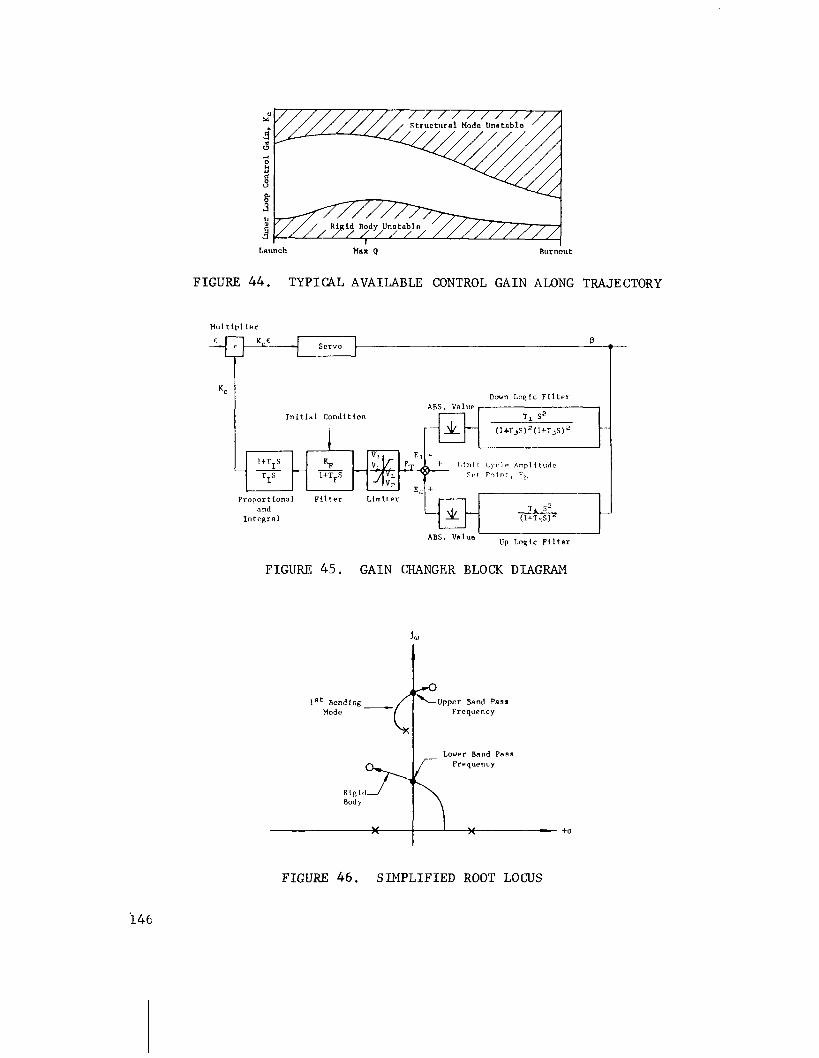
sU
4" 3 4
I 8. 3 t,
8 H
Lnunch Max Q Burnout
FIGURE 44. TYPICAL AVAILABLE CONTROL GAIN ALONG TRAJECTORY
Mul tlpl ier
Servo B
T
Down Loglc Filter ABS. V ~ l u e
Initlal Condition 1 T 7 s2 1
Proportional Filter Limiter -' I - 7 and
Integral
ABS. value I Up Logic Filter
FIGURE 45. GAIN CHANGER BLOCK DIAGRAM
lRt Bending- \upper Band Pass Mode Frequency
I Lower Band Pass
"rl! Frequency
FIGURE 4 6 . S I M P L I F I E D ROOT L O W S
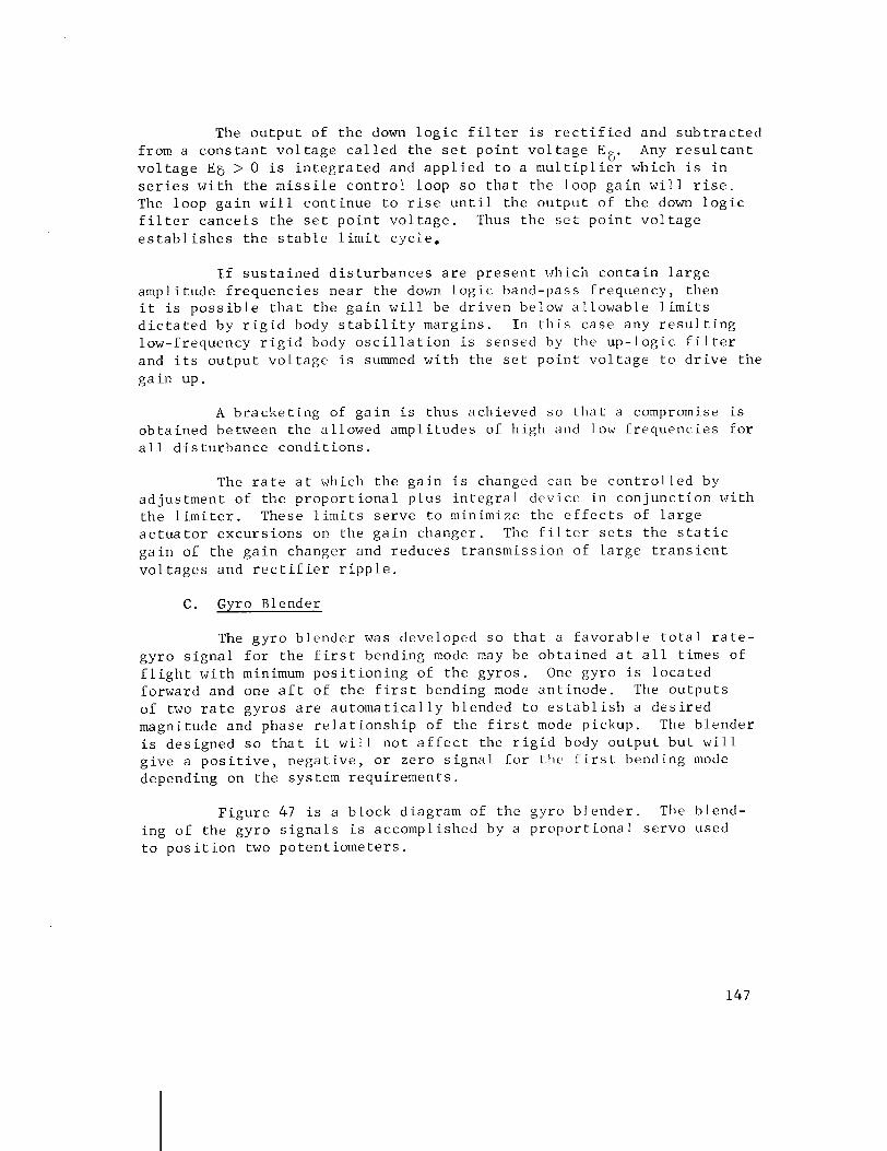
The o u t p u t of t h e down l o g i c f i l t e r i s r e c t i f i e d and s u b t r a c t e d from a c o n s t a n t v o l t a g e c a l l e d t h e s e t p o i n t v o l t a g e E8. Any r e s u l t a n t v o l t a g e E E > 0 is i n t e g r a t e d and a p p l i e d t o a m u l t i p l i e r which is i n s e r i e s w i t h the m i s s i l e c o n t r o l loop s o t h a t t h e loop g a i n w i l l r i s e . The loop g a i n w i l l c o n t i n u e t o r i s e u n t i l t h e o u t p u t of t h e down l o g i c f i l t e r c a n c e l s the s e t p o i n t v o l t a g e . Thus t h e s e t p o i n t v o l t a g e e s t a b l i s h e s t h e s t a b l e l i m i t c y c l e ,
I f s u s t a i ~ l e d d i s t u r b a n c e s a r e p r e s e n t which c o n t a i n l a r g e ampl i tude f r e q u e n c i e s nea r the down l o g i c band-pass f requency , then i t i s p o s s i b l e t h a t t h e g a i n w i l l be d r i v e n below a l l o w a b l e l i m i t s d i c t a t e d by r i g i d body s t a b i l i t y marg ins . I n t h i s c a s e any r e s u l t i n g low-frequency r i g i d body o s c i l l a t i o n i s sensed by the u p - l o g i c f i l t e r and i t s o u t p u t v o l t a g e i s summed w i t h the s e t p o i n t v o l t a g e t o d r i v e the g a i n up.
A b r a c k e t i n g of g a i n i s thus ach ieved s o t h a t a compromise i s o b t a i n e d between the a l lowed ampl i tudes of h i g h and low f r e q u e n c i e s f o r a l l d i s t u r b a n c e c o n d i t i o n s .
The r a t e a t which t h e g a i n i s changed can be c o n t r o l l e d by ad jus tment of t h e p r o p o r t i o n a l p l u s i n t e g r a l dev ice i n c o n j u n c t i o n w i t h t h e l i m i t e r . These l i m i t s s e r v e t o minimize the e f f e c t s of l a r g e a c t u a t o r e x c u r s i o n s on t h e g a i n changer . The i i l t c r s e t s t h e s t a t i c g a i n of t h e g a i n changer and reduces t r a n s m i s s i o n of l a r g e t r a n s i e n t v o l t a g e s and r e c t i f i e r r i p p l e .
C . Gyro Blender
The g y r o b l e n d e r was developed s o t h a t a f a v o r a b l e t o t a l r a t e - g y r o s i g n a l f o r the f i r s t bending mode may be o b t a i n e d a t a l l t imes of f l i g h t w i t h minimum p o s i t i o n i n g of t h e gyros . One gyro i s l o c a t e d forward and one a f t of t h e f i r s t bending mode a n t i n o d e . The o u t p u t s of two r a t e gyros a r e a u t o m a t i c a l l y b lended t o e s t a b l i s h a d e s i r e d magnitude and phase r e l a t i o n s h i p of the f i r s t mode pickup. The b l e n d e r i s des igned s o t h a t i t w i l l n o t a f f e c t the r i g i d body o u t p u t b u t w i l l g i v e a p o s i t i v e , n e g a t i v e , o r ze ro s i g n a l f o r t h e f i r s t bending mode depending on t h e system r e q u i r e m e n t s .
F i g u r e 47 i s a b lock diagram of t h e gyro b l e n d e r . The b lend- ing of t h e g y r o s i g n a l s is accomplished by a p r o p o r t i o n a l s e r v o used t o p o s i t i o n two p o t e n t i o m e t e r s .
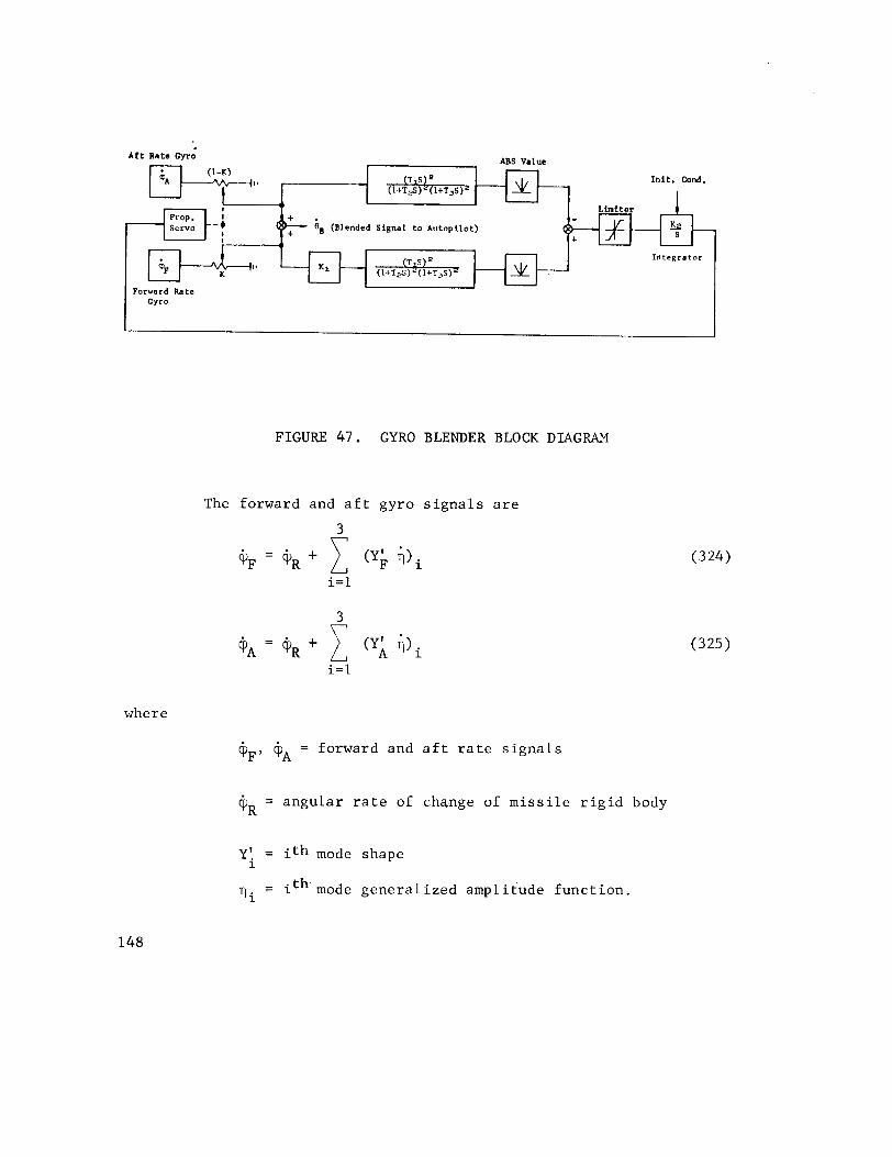
Aft Rate Gyro ABS Value ( 1 - K ) p+.+++,, -
Inlt. Cond.
41
eg (Blended Signal to Autopilot)
( T I S ) ~ Integrator
(I+T~s)'(~+T,~
Forward Rate
FIGURE 47. GYRO BLENDER BLOCK DIAGRAM
The forward and a f t g y r o s i g n a l s a r e
where
eE, = forward and a f t r a t e s i g n a l s
+R = a n g u l a r r a t e of cha,nge of m i s s i l e r i g i d body
Y! = i t h mode shape 1
T i = ith mode g e n e r a l i z e d amp1 i t u d e f u n c t i o n .
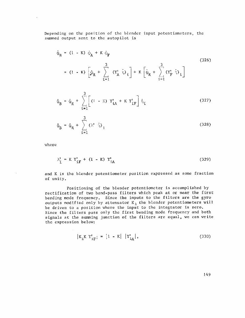
Depending on the p o s i t i o n of the blender input po ten t iometers , the summed output s e n t t o the a u t o p i l o t i s
where
and K i s the blender potent iometer p o s i t i o n expressed a s some f r a c t i o n of un i ty .
Pos i t i on ing of the blender potent iometer i s accomplished by r e c t i f i c a t i o n of two band-pass f i l t e r s which peak a t or near the f i r s t bending mode frequency. Since the inputs t o the f i l t e r s a r e t he gyro outputs modified only by a t t e n u a t o r K1 the blender potent iometers w i l l be dr iven t o a p o s i t i o n where the input t o the i n t e g r a t o r i s zero. Since the f i l t e r s pass only the f i r s t bending mode frequency and both s i g n a l s a t the summing junct ion of the f i l t e r s a r e equal , we can w r i t e t he express ion below:
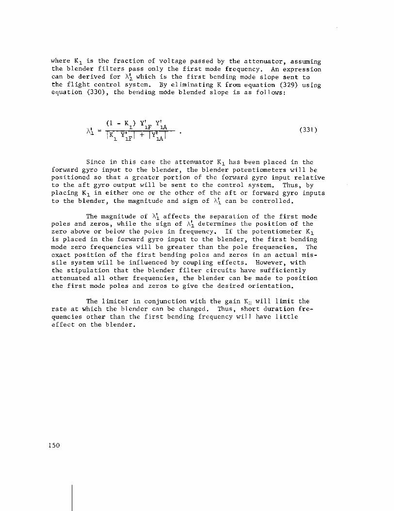
where K1 i s the f r a c t i o n of vo l t age passed by the a t t e n u a t o r , assuming the blender f i l t e r s pass only the f i r s t mode frequency. An expression can be der ived f o r A\ which i s the f i r s t bending mode s lope s e n t t o the f l i g h t con t ro l system. By e l imina t ing K from equat ion (329) using equat ion (330), the bending mode blended s lope i s a s follows:
Since i n t h i s case the a t t e n u a t o r K1 has been placed i n the forward gyro input t o the blender , the blender potent iometers w i l l be pos i t ioned s o t h a t a g r e a t e r por t ion of the forward gyro input r e l a t i v e t o t h e a f t gyro output w i l l be s e n t t o the con t ro l system. Thus, by p lac ing K1 i n e i t h e r one or the o the r of the a f t o r forward gyro inpu t s t o the b lender , t he magnitude and s i g n of A \ can be con t ro l l ed .
The magnitude of A: a f f e c t s the sepa ra t ion of the f i r s t mode poles and zeros , whi le the s ign of A\ determines the p o s i t i o n of the zero above o r below the poles i n frequency. I f the potent iometer K1 i s placed i n the forward gyro input t o t he blender , t h e f i r s t bending mode zero f requencies w i l l be g r e a t e r than the pole frequencies . The exac t p o s i t i o n of t he f i r s t bending poles and zeros i n an a c t u a l mis- s i l e system w i l l be inf luenced by coupling e f f e c t s . However, w i th the s t i p u l a t i o n t h a t the blender f i l t e r c i r c u i t s have s u f f i c i e n t l y a t t enua ted a l l o ther f requencies , the blender can be made t o pos i t i on the f i r s t mode poles and zeros t o g ive the des i r ed o r i e n t a t i o n .
The l i m i t e r i n conjunct ion wi th the ga in K2 w i l l l i m i t the r a t e a t which the blender can be changed. Thus, s h o r t du ra t ion f r e - quencies o the r than the f i r s t bending frequency w i l l have l i t t l e c f f e c t on the blender .
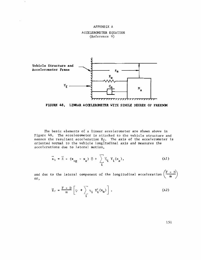
APPENDIX A
ACCELEROMETER EQUATION (Reference 9)
FIGURE 48. LINEAR ACCZLEROMETER WITH SINGLE DEGREE OF FREEDOM
\ \
Vehicle Structure and \ -
Accelerometer Frame \: \
The basic elements of a linear accelerometer are shown above in Figure 48. The accelerometer is attached to the vehicle structure and senses the resultant acceleration Zf. The axis of the accelerometer is oriented normal to the vehicle longitudinal axis and measures the accelerations due to lateral motion,
=a L
and due to the lateral component of the longitudinal acceleration ?+) or,
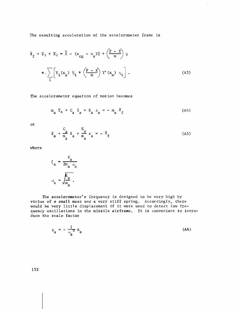
The r e s u l t i n g a c c e l e r a t i o n of the accelerometer frame i s
The accelerometer equat ion of motion becomes
.. m Z a + C i + K z = - m
a a a a a a f
C K . . a a i + - z + - 2 = - E a m a m a a a
f
where
The a c c e l e r m e t e r l s frequency i s designed t o be very high by v i r t u e of a small mass and a very s t i f f spr ing . Accordingly, there would be very l i t t l e displacement i f it were used t o d e t e c t low f r e - quency . o s c i l l a t i o n s i n the m i s s i l e a i r f rame. It i s convenient t o i n t r o - duce the s c a l e f a c t o r
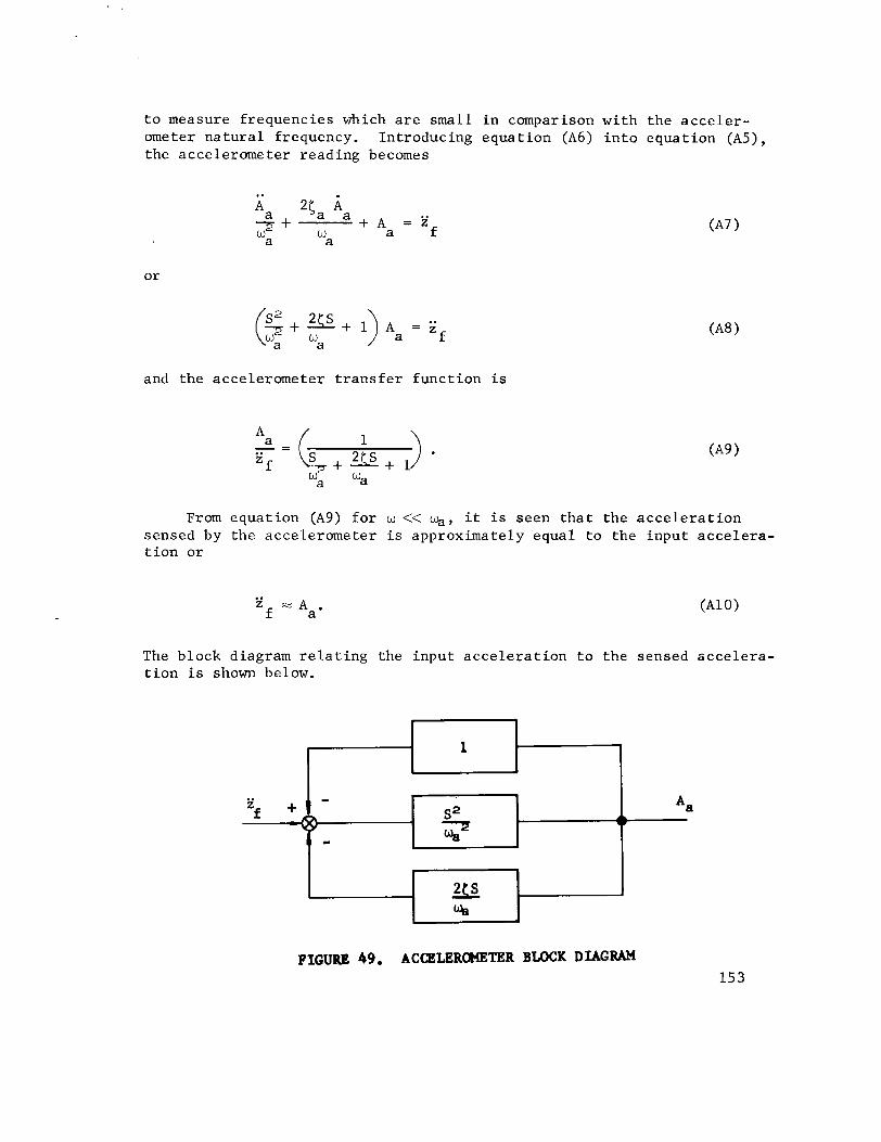
t o measure f requencies which a r e small i n comparison wi th the a c c e l e r - ometer n a t u r a l frequency. Introducing equat ion (A6) i n t o equat ion ( A 5 ) , the accelerometer reading becomes
and the accelerometer t r a n s f e r func t ion is
From equat ion (A9) f o r w << %, it i s seen t h a t the a c c e l e r a t i o n sensed by the accelerometer i s approximately equal t o the input acce l e ra - t i o n o r
The block diagram r e l a t i n g the input a c c e l e r a t i o n t o the sensed acce l e ra - t i o n is shown below.
FIGURE 49. ACQZLEROMETER BLOCK DIAGRAM

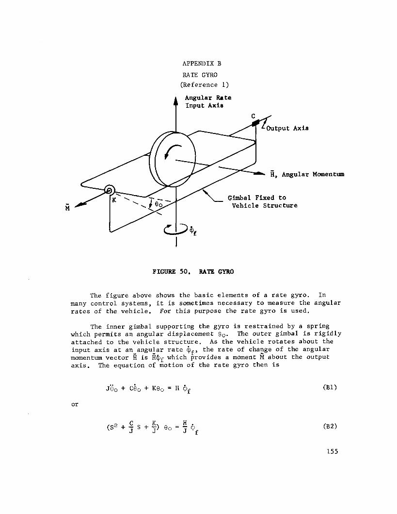
APPENDIX B
RATE GYRO
(Reference 1)
Angular Rate Input Axis
Vehicle S t r u c t u r e
FIGURE 50. RATE GYRO
The f i g u r e above shows the b a s i c elements of a r a t e gyro. In many con t ro l systems, i t i s sometimes necessary t o measure the angular r a t e s of t he veh ic l e . For t h i s purpose the r a t e gyro i s used.
The inner gimbal support ing the gyro i s r e s t r a i n e d by a spr ing which permits an angular displacement 9,. The ou te r gimbal is r i g i d l y a t t ached t o t he v e h i c l e s t r u c t u r e . As the v e h i c l e r o t a t e s about the input a x i s a t an angular r a t e @£, t he r a t e of change of the angular momentum vec to r fi i s HQf which provides a moment 6 about the output a x i s . The equat ion of motion of the r a t e gyro then i s
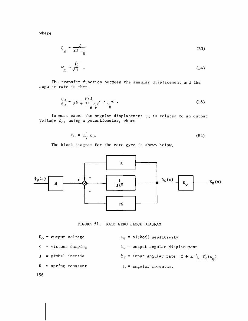
where
The t r a n s f e r func t ion between the angular displacement and the angular r a t e is then
In most cases the angular displacement O,, i s r e l a t e d t o an output v o l t a g e E,, using a po ten t iometer , where
E, = Kv eO. ( B 6 )
The block diagram f o r the r a t e gyro is shown below.
FIGURE 51. RATE GYRO BLOCK DIAGRAM
Eo = output vo l t age K, = pickoff s e n s i t i v i t y
C = viscous damping
J = gimbal i n e r t i a
K = sp r ing cons tan t
156
Q0 = output angular displacement
Gf = input angular r a t e iy + Z ili Y;(x ) cP
H = angular momentum.
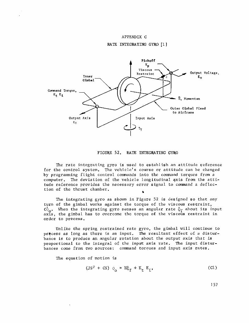
APPENDIX C
RATE INTEGRATING GYRO 11 ]
Output Vol E 0
Corrnnand Torque,
Kt Ei
t a g e ,
FIGURE 52. RATE INTEGRATING GYRO
The r a t e i n t e g r a t i n g gyro i s used t o e s t a b l i s h an a t t i t u d e r e f e r ence f o r the con t ro l system. The v e h i c l e ' s course o r a t t i t u d e can be changed by programming f l i g h t con t ro l commands i n t o the command torques from a computer. The d e v i a t i o n of the v e h i c l e l ong i tud ina l ?x i s from the a t t i - tude r e f e r ence provides the necessary e r r o r s i g n a l t o command a de f l ec - t i o n of the t h r u s t chamber.
b
The i n t e g r a t i n g gyro a s shown i n Figure 52 is designed s o t h a t any tu rn of the gimbal works a g a i n s t the torque of the v i scous r e s t r a i n t , cQ,. When the i n t e g r a t i n g gyro senses an angular r a t e @f about i ts input a x l s , the gimbal has t o overcome the torque of the v i scous r e s t r a i n t i n order t o precess .
Unlike the sp r ing r e s t r a i n e d r a t e gyro, the gimbal w i l l con t inue t o prkcess a s long a s t h e r e i s an input . The r e s u l t a n t e f f e c t of a d i s t u r - bance is t o produce an angular r o t a t i o n about the ou tput a x i s t h a t is p ropor t i ona l t o the i n t e g r a l of the i npu t a x i s r a t e . The inpu t d i s t u r - bances come from two sources : command torclues and inpu t a x i s r a t e s .
The equat ion of motion i s
( J S ~ + CS)
and the r e spec t ive t r a n s f e r func t ions a r e
Command Torques:
where
Input Axis Rates:
The t o t a l t r a n s f e r func t ion i s
The block diagram of the r a t e i n t e g r a t i n g gyro i s shown i n Figure 5 3 .
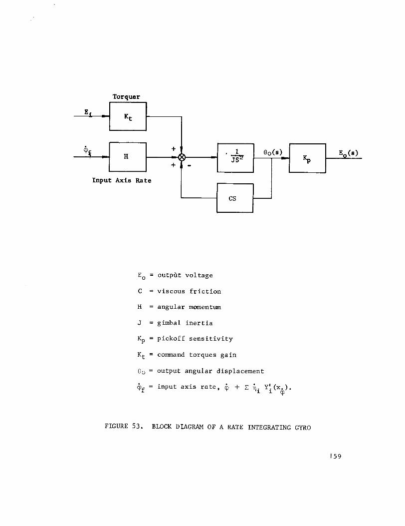
Torquer
Input Axis Rate 47-1 Eo = ou tpa t vo l tage
C = viscous f r i c t i o n
H = angular momentum
J = gimbal i n e r t i a
Kp = pickoff s e n s i t i v i t y
Kt = command torques ga in
Q 0 = output angular displacement
Gf = input a x i s r a t e , 6, + ,Z fii Y i ( x . ) . cp
FIGURE 53. BLOCK DIAGRAM OF A RATE INTEGRATING GYRO
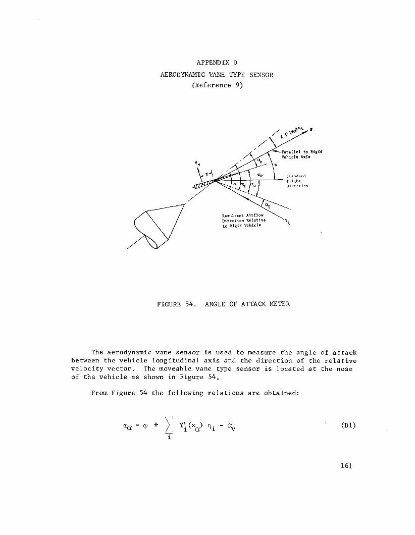
A P P E N D I X D
AERODYNAMIC VANE TYPE SENSOR
(Reference 9)
Res~l l tant Airflow Direction Relative t o ~ i g l d Vehlcle
\ v~
FIGURE 54. ANGLE O F ATTACK METER
The aerodynamic vane sensor i s used t o measure the angle of a t t a c k between the v e h i c l e l ong i tud ina l a x i s and the d i r e c t i o n of the r e l a t i v e v e l o c i t y vec to r . The moveable vane type sensor i s loca ted a t the nose of the v e h i c l e a s shown i n Figure 54.
From Figure 54 the following r e l a t i o n s a r e obtained:
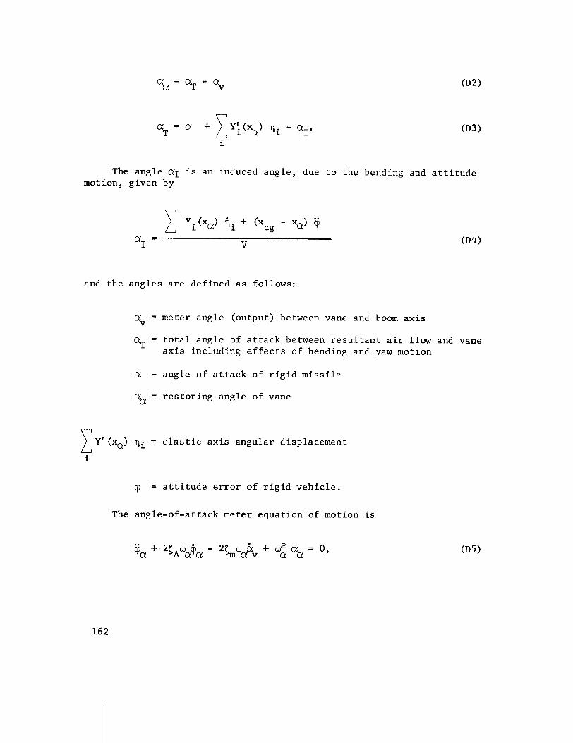
The angle a1 i s an induced angle, due t o the bending and a t t i t u d e motion, given by
and the angles a r e def ined a s follows:
% = meter angle (output) between vane and boom a x i s
c+ = t o t a l angle of a t t a c k between r e s u l t a n t a i r flow and vane a x i s including e f f e c t s of bending and yaw motion
a = angle of a t t a c k of r i g i d m i s s i l e
a, = r e s t o r i n g angle of vane
Y' (xa) qi = e l a s t i c a x i s angular displacement
i
= a t t i t u d e e r r o r of r i g i d veh ic l e .
The angle-of-at tack meter equat ion of motion i s
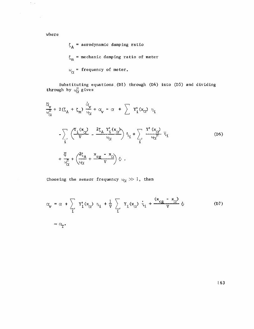
where
SA = aerodynamic damping r a t i o
tm = mechanic damping r a t i o of meter
w = frequency of meter. a
Subs t i t u t ing equa t ions . (Dl) through (D4) i n t o (D5) and d iv id ing through by 6 g ives
Choosing the sensor frequency % >> 1, then

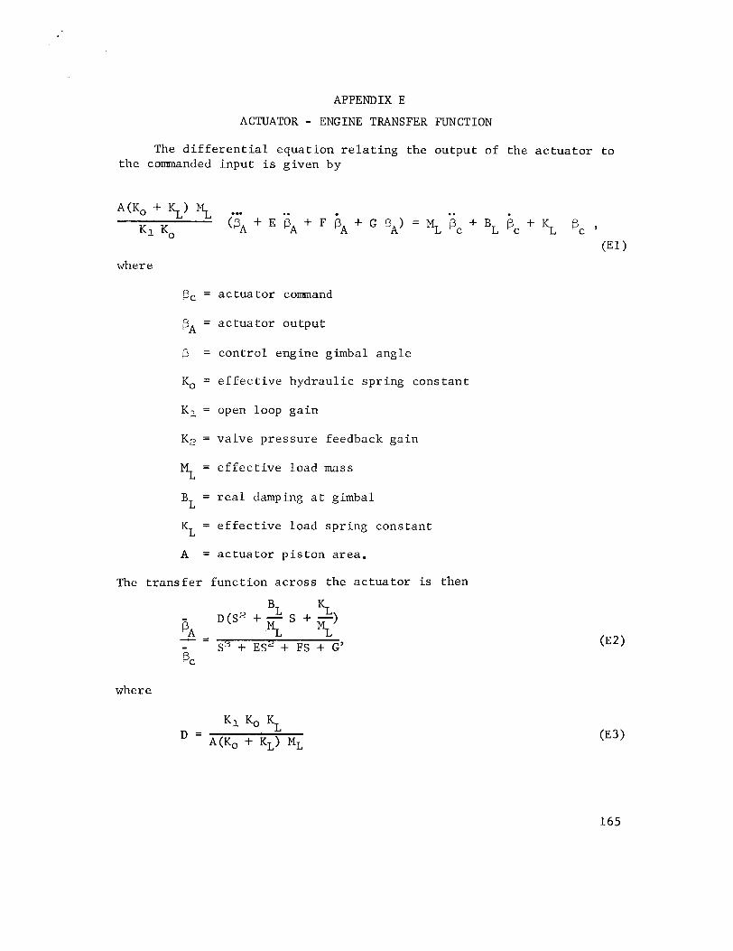
APPENDIX E
ACTUATOR - ENGINE TRANSFER FUNCTION
The d i f f e r e n t i a l equat ion r e l a t i n g the output of the a c t u a t o r t o t he commanded input is given by
A m 0 + KL) i',$, (FA + E iA + F bA + G PA) = ML . PC . + BL Bc + 5 'c ' K l KO (El)
where
pc = a c t u a t o r command
PA = a c t u a t o r ou tput
p = con t ro l engine gimbal angle
KO = e f f e c t i v e hydrau l i c spr ing cons tan t
K1 = open loop ga in
K, = valve pressure feedback gain
3 = e f f e c t i v e load mass
BL = r e a l damping a t gimbal
KL = e f f e c t i v e load spr ing cons tan t
A = a c t u a t o r p i s ton a rea .
The t r a n s f e r func t ion across the a c t u a t o r i s then
where

The d i f f e r e n t i a l equat ion r e l a t i n g the engine gimbal angle and ac tua to r ou tput i s
and has t h e t r a n s f e r func t ion
The d e t a i l e d block diagram of the ac tua to r i s shown i n Figure 55.

B~ ( s 2 + s + r + 5,
B~ s 2 + - S + Et "3
ML (5, + El,
L L s 2 + - s + - El, M~
FIGURE 55. BLOCK DIAGRAM OF ACTUATOR AND ENGINE


APPENDIX F
The e q u a t i o n s included i n t h i s appendix a r e w r i t t e n f o r a v e h i c l e i n t h e X , Z c o o r d i n a t e system. The'X a x i s is chosen t a n g e n t t o t h e r e f e r e n c e f l i g h t p a t h moving w i t h t h e v e l o c i t y and a c c e l e r a t i o n of t h e l o n g i t u d i n a l v e h i c l e t r a n s l a t i o n . Choosing t h e c o o r d i n a t e sys tem i n t h i s manner e l i m i n a t e s t h e degree o f freedom a long X whose i n f l u e n c e on t h e s t a b i l i t y behav ior of t h e v e h i c l e is cons idered n e g l i g i b l e .
For s t a b i l i t y i n v e s t i g a t i o n s of t h e v e h i c l e mot ion, o n l y a s h o r t i n t e r v a l of f l i g h t t ime is t aken . The r o t a t i o n of t h e s t a n d a r d f l i g h t p a t h d i r e c t i o n is n e g l e c t e d , and a l l v e h i c l e parameters ( t h r u s t , mass, aerodynamic, e c t . ) a r e assumed c o n s t a n t .
The degrees of freedom of t h e v e h i c l e a r e
1. l a t e r a l t r a n s l a t i o n of t h e v e h i c l e r i g i d body, Z
2. r o t a t i o n of t h e v e h i c l e r i g i d body r e l a t i v e t o a n i n e r t i a l sys tem, q
3 . r o t a t i o n of the swive l eng ine r e l a t i v e t o a n i n e r t i a l sys tem, +
4 . disp lacement o f k p r o p e l l a n t s l o s h masses , Zsk
5. ampl i tude of i bending modes, v i , and
6 . t h e s w i v e l engine compliance, f3 - PC.
The t o t a l number of t h e degrees of freedom f o r t h i s sys tem i s then
The fo l lowing e q u a t i o n s can be d e r i v e d by a p p l i c a t i o n of Lagrange 's e q u a t i o n t o t h e k i n e t i c , p o t e n t i a l , and d i s s i p a t i v e energy of t h e s y s tem a s was done f o r t h e bending and s l o s h e q u a t i o n i n S e c t i o n V.
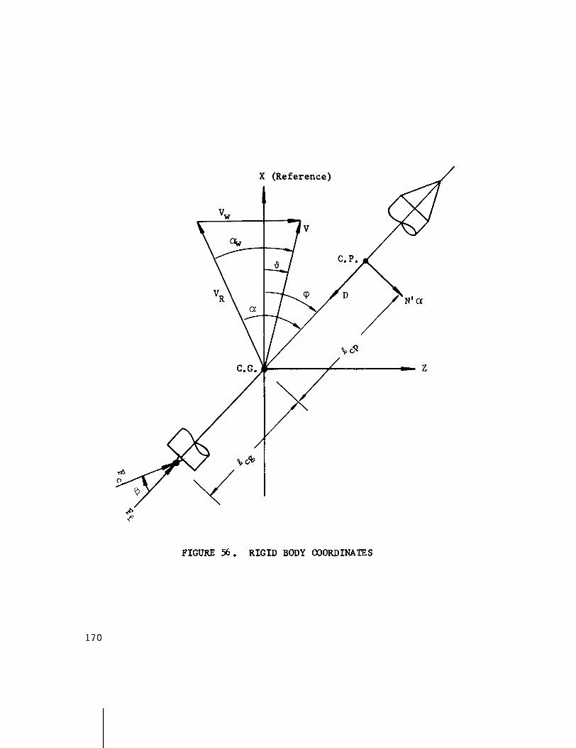
F
FIGURE 56 . RIGID BODY COORDINATES
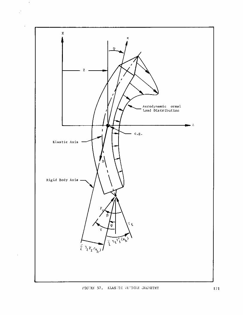
- X
A X
-
E l a s t i c A x i s
R i g i d B o d y A x i s
i
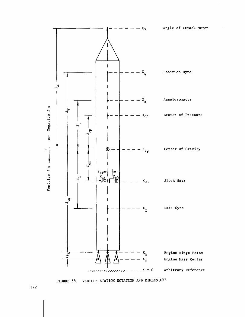
Angle o f Attack Meter
Pos i t i on Gyro
Accelerometer
Center of Pressure
Center of Gravity
Slosh Maas
Rate Gyro
Engine Hinge Point
Engine Mass Center
Arbitrary Reference
FIGURE 58. VEHICLE STATION NOTATION AND DIMENSIONS
Angular A c c e l e r a t i o n abou t Center of G r a v i t y
where
A c c e l e r a t i o n Normal t o Vehic le Reference a t Center of G r a v i t y
.. m - E z,, - - - M C [ Y i ( x h ) + e ~ ~ h y!(x ) I ? , + I ~ ; ( x ~ ) T ~
A c c e l e r a t i o n Normal t o Vehicle Longi tud ina l Axis a t Sensor Loca t ion , x a
Bending Equat ion f o r ith Bending Mode

where
F - D i=- M
M~ = j m1 (x) [yi (x) I dx (modal mass).
S l o s h Equa t ion f o r k th S l o s h Mode
Angular R e l a t i o n s
- - - vw aw v (yaw p l a n e )
v cos X W C
= t an ' l ( p i t c h p l a n e ) . V - V s i n X
W C

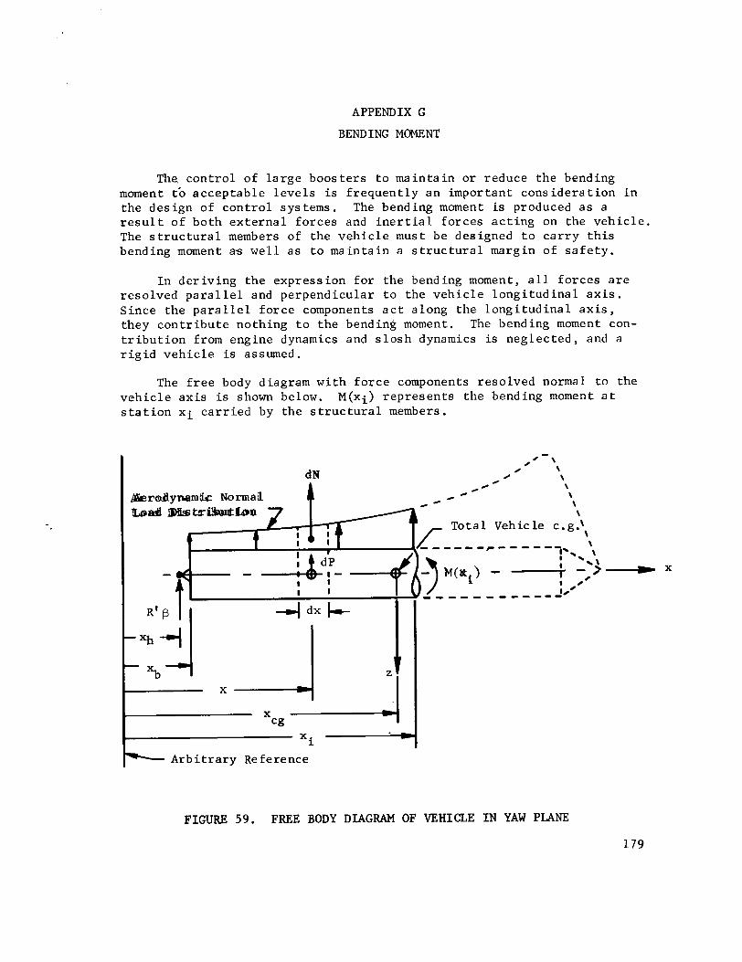
APPENDIX G
BENDING MOMENT
The. c o n t r o l o f l a r g e b o o s t e r s t o m a i n t a i n o r reduce t h e bending moment tb a c c e p t a b l e l e v e l s i s f r e q u e n t l y a n impor tan t c o n s i d e r a t i o n i n t h e d e s i g n of c o n t r o l s y s tems. The bending moment is produced a s a r e s u l t o f b o t h e x t e r n a l f o r c e s and i n e r t i a l f o r c e s a c t i n g on t h e v e h i c l e . The s t r u c t u r a l members of t h e v e h i c l e must be des igned t o c a r r y t h i s bending moment a s w e l l a s t o m a i n t a i n a s t r u c t u r a l margin o f s a f e t y .
I n d e r i v i n g t h e e x p r e s s i o n f o r t h e bending moment, a l l f o r c e s a r e r e s o l v e d p a r a 1 l e l and p e r p e n d i c u l a r t o t h e v e h i c l e l o n g i t u d ina 1 a x i s . S i n c e t h e p a r a l l e l f o r c e components a c t a long t h e l o n g i t u d i n a l a x i s , they c o n t r i b u t e n o t h i n g t o t h e bending moment. The bending moment con- t r i b u t i o n from eng ine dynamics and s l o s h dynamics is n e g l e c t e d , and a r i g i d v e h i c l e is assumed.
The f r e e body diagram w i t h f o r c e components r e s o l v e d normal t o t h e v e h i c l e a x i s is shown below. M(xi) r e p r e s e n t s t h e bending moment a t s t a t i o n x i c a r r i e d by t h e s t r u c t u r a l members.
,/-\
dN / \
A 0 / \
/ 0 \
&rdynembtc Normal d @
e \
I D j h t r h d b ~ \ \
T o t a l Vehicle c.g.\ 1
- - - - r - - - - - \ I-.. \ \ \
M(xi) - -i -,3 ' .'
- , - , , - - - - J '
- A r b i t r a r y Reference
FIGURE 59. FREE BODY DIAGRAM OF VEHICLE IN YAW PLANE
179

The f o r c e s a c t i n g on an e lement dx a r e t h e aerodynamic normal f o r c e ,
and t h e i n e r t i a l f o r c e
d P = m' (x) 'i (x) dx. (G2)
The prime i n t h e two equa t ions above denotes a d e r i v a t i v e w i t h r e s p e c t t o x.
The moment a t s t a t i o n xi . due t o dN, dP and R' is
Xi-xb
M(x) = R1f3(x - xh) + i [dN + dP1 (xi - x ) .
"b
A f t e r e x p r e s s i o n s (Gl) and G(2) a r e s u b s t i t u t e d i n t o (G3),
The a c c e l e r a t i o n ' i (x) i n e q u a t i o n (G4) can be w r i t t e n i n terms of a and f3, s i n c e
and, from e q u a t i o n s (39) and (40) ,

Therefore ,
Now w r i t i n g equat ion (G4) i n terms of a and p using equa t ion (G8) g ives
Fac tor ing the q u a n t i t i e s ou t s ide the i n t e g r a l i n equa t ion (G9) which a r e independent of x r e s u l t s i n a bending moment equa t ion of the form
where
xi-x,,
M (xi) = R' (xi - xh) + m "' S m' (x) (xi - x) dx B
+ I "c. - jl "
m' (x) (xi - X) (xcg - X) dx.
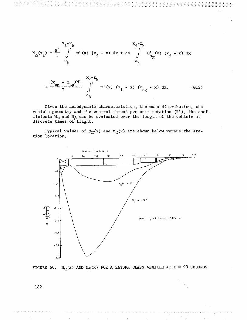
Given the aerodynamic character is t i c s , the mass d i s t r ibu t ion , the vehic le geometry and the control t h ru s t per u n i t r o t a t i on (R' ), the coef- f i c i e n t s and MB can be evaluated over the length of the veh ic le a t d i s c r e t e times of f l i g h t .
Typical values of &(x) and MB(x) a r e shown below versus the s t a - t ion locat ion.
FIGURE 60. Q(x) AND Mg(x) FOR A SATURN CLASS VEHICLE AT t = 93 SECONDS
When a bending moment expression i s requi red i n making a c o n t r o l s tudy ( i . e . , shaping the a and f3 response t o reduce bending moment), t he po in t of maximum bending i s the one of i n t e r e s t . For the v e h i c l e above, t h i s would occur i n a reg ion around s t a t i o n 22 meters depending on the time h i s t o r y response of a and p. Assuming the response was such t h a t the bending moment is maximum a t s t a t i o n 22 meters , the expression i n t h i s case would be
REFERENCES
Lukens, Schmi t t and Broucek, "Approximate T r a n s f e r Func t ions f o r F l e x i b l e - Booster - and A u t o p i l o t A n a l y s i s , " WADD TR-61-98, A p r i l 1961,
Bauer, H. F., "Mechanical Analogy of F l u i d O s c i l l a t i o n s i n C y l i n d r i c a l Tanks w i t h C i r c u l a r and Annular Cross S e c t i o n s , " MTP-AERO-61-4, January 12 , 1961, U n c l a s s i f i e d .
Honeywell, "Study of t h e Control and Dynamic S t a b i l i t y Problem of t h e S a t u r n Space Vehic le ," R-ED5114, January 26, 1961.
Hoelker , R. F., "Theory of A r t i f i c i a l S t a b i l i z a t i o n of M i s s i l e s and Space Veh ic les w i t h E x p o s i t i o n of Four Control P r i n c i p l e s , " NASA TN D-555, June 1961, U n c l a s s i f i e d .
Bauer, H. F., " I n f l u e n c e of P r o p e l l a n t S losh ing upon t h e S t a b i l i t y of a Space Vehic le ," MTP-AERO-62-76, March 15, 1962, U n c l a s s i f i e d .
Bauer, H. F. and Mario R h e i n f u r t h , " F l u t t e r and S t a b i l i t y A n a l y s i s , " DA-TM-4-60, January 12, 1960, U n c l a s s i f i e d .
Del Toro and P a r k e r , " P r i n c i p l e s of Con t ro l Systems Engineer ing , " McGraw H i l l , 1960.
Gardner and Barnes , T r a n s i e n t s i n L i n e a r Sys tems, John Wiley & Sons, I n c . , New York, 1942.
RheinEurth , Mario H. , "Control Feedback S t a b i l i t y Ana lys i s ," DA-TR-2-60, U n c l a s s i f i e d .
The Boeing Company, "Proposal f o r t h e Development of a Load A l l e v i a t i n g Cont ro l System f o r a Large F l e x i b l e Launch Veh ic le , " DZ-22911, November 1963.
1 1 D a n i e l s , G , E., N a t u r a l Environment ( C l i m a t i c C r i t e r i a ) G u i d e l i n e s f o r Use i n MSFC Launch Veh ic le Development ," MTP-AERO-63-8, January 28, 1963, U n c l a s s i f i e d .
Scoggins , J. R. and W. W. Vaughan, "Cape Canaveral Wind and Shear Date (1 th rough 80 KM) f o r Use i n Vehic le Design and Performance S t u d i e s ," NASA TN D11274, J u l y 1962,
Vaughan, W. W . , " S i n u s o i d a l Gust C r i t e r i a G u i d e l i n e s f o r Apol lo Emergency D e t e c t i o n System Angular Rate S t u d i e s , " Memorandum da ted June 22, 1964.
APPROVAL NASA TM X-53036
CONTROL THEORY HANDBOOK
By Doyle Garner
The i n f o r m a t i o n i n t h i s r e p o r t has been reviewed f o r s e c u r i v c l a s s i f i c a t i o n . Review of any in format ion concerning Department of Defense o r Atomic Energy Commission programs has been made by t h e MSFC S e c u r i t y C l a s s i f i c a t i o n O f f i c e r . This r e p o r t , i n i t s e n t i r e t y , has been determined t o be u n c l a s s i f i e d .
This document has a l s o been reviewed and approved f o r t e c h n i c a l accuracy .
/ C h i e f , Advanced Control S e c t i o n
- - I
Mario H. R h e i n f u r t h r
Chief , Control S t u d i e s Branch
- Helmut J. Horn Chief , Dynamics and F l i g h t Mechanics D i v i s i o n
E . D. G e i s s l e r D i r e c t o r , Aero-As trodynamics Laboratory
D I S T R I B U T I O N
D I R R - A S T R ( ~ o n t ' d ) M r . G r i s w o l d
D E P - T
M S - I P
M S - I L (8)
I-RM-M
C C - P
R-P&VE D i r e c t o r D r . E u l i t z M r . H e 1 lebrand M r . K r o l l M r . B o b H u n t D r . G l a s e r M r . N a t h a n S h o w e r s M r . G u d z e n t
R - A S T R D r . H a e u s s e r m a n n M r . H o s e n t h i e n (5) M r . B . M o o r e M r . J u s t i c e M r . B l a c k s tone M r . M i n k M r . G u n d e r s o n M r . J ack G e o r g e M r . A s n e r (4) M r . C l a r k M r . V a l l e r y M r . R i t t e r M r . H o s e M r . C. 0. Jones M r . K e n n e l M r . Paul Fisher M r . M c A u l e y M r . S t a n C a r r o l l M r . B o r e l l i M r . L a n d w e h r
M r . S t o v e r M r . V i r g i n M r . S c o f f i e l d M r . B u d G e o r g e M r . R i c h a r d H a l l
R- COMP D i r e c t o r M i s s M a b l e M o r g a n M r . M c G a r r i t y M r . C h a r l e s B r a d s h a w D r . P o l s t o r f f M r . F r ed Shaver
R - T E S T M r . H e i m b u r g M r . T e s s m a n M r . K r a m e r D r . S i e b e r M r . S c h u l e r D r . Lackner D r . R e i s i g
R- AERO D r . G e i s s l e r M r . Jean M r . H o r n M r . D a h m M r . R e e d D r . S p e e r M r . R h e i n £ u r t h M r . H a r t M r . G o l m a n M r . S t o n e M r . B a k e r M r . T h o m a e M r . von P u t t k a m e r M r . Funk M r . W o o d M r . S c o t t M r . V e r d e r a i m e M r . T e u b e r M r . R y a n (10)
DISTRIBUTION (Continued)
R-AERO ( ~ o n t ' d ) D r . McDonough M r . Townsend M r . S w i f t Mrs . King M r . Harcrow M r . K i e f l i n g M r . Pack M r . B l a i r M r . Redus M r . Garner (40) M r . L iv ings t o n D r . Ford D r . Davis M r . C a r t e r M r . Brady M r . Mowery M r . B. G . Davis Miss Hopkins M r . S c h e r e r M r . H a l l M r s . Harmon M r . Hammer M r . A. W. Deaton Mrs. Chandler M r . Cooper M r . Cremin M r . G i l l i s M r . W. Vaughan M r . J. Her r ing M r . W . Heuser M r . Sumral l M r . Cummings M r . 0. B. Vaughan M r . Scoggins M r . Mi lner M r . Lovingood M r . Lewis, (10)
Technica l & S c i e n t i f i c I n f o . F a c i l i t y (25) P. 0. Box 5700 Be thesda , Md . Attn: NASA Rep. (s-AK/RKT)