contents crane control · 2020-04-24 · january 2010 2 for more information visit: ca05801001e...
TRANSCRIPT

January 2010
CA05801001E For more information visit: www.eaton.com
Contents
Crane Control 1
Cra
ne C
on
tro
lDescription Page
Heavy-Duty Brakes
Shoe Brakes — Magnetically Operated . . . . . . . . . . . . . . . . . . . . . . . . . . . 2
Master and Limit Switches
Type F Master Switches — GH101 . . . . . . . . . . . . . . . . . . . . . . . . . . . . . . . 22
Type C Master Switches — GH103 . . . . . . . . . . . . . . . . . . . . . . . . . . . . . . . 28
Crane Power Limit Switches . . . . . . . . . . . . . . . . . . . . . . . . . . . . . . . . . . . . 30
Heavy-Duty Control Limit Switches — Type E84 . . . . . . . . . . . . . . . . . . . . 35
High Speed Limit Switches . . . . . . . . . . . . . . . . . . . . . . . . . . . . . . . . . . . . . 40
Foot-Operated Limit Switches. . . . . . . . . . . . . . . . . . . . . . . . . . . . . . . . . . . 41
Cable-Operated Limit Switches. . . . . . . . . . . . . . . . . . . . . . . . . . . . . . . . . . 42
Contactors and Relays
DC Contactors . . . . . . . . . . . . . . . . . . . . . . . . . . . . . . . . . . . . . . . . . . . . . . . . 43
DC Timers — Static In-Line . . . . . . . . . . . . . . . . . . . . . . . . . . . . . . . . . . . . . 66
Low Voltage Monitoring Relays . . . . . . . . . . . . . . . . . . . . . . . . . . . . . . . . . 67
DC Relays . . . . . . . . . . . . . . . . . . . . . . . . . . . . . . . . . . . . . . . . . . . . . . . . . . . 68
DC Timing Relays — 7313 VTH and 7313 CTH . . . . . . . . . . . . . . . . . . . . . . 78
Contactors and RelaysMaster and Limit Switch Family
Heavy-Duty Brakes

January 2010
2
For more information visit: www.eaton.com CA05801001E
Crane ControlHeavy-Duty BrakesShoe Brakes — Magnetically Operated
30” Size GH505 Magnetic Shoe Brake
Product DescriptionThe GH505 Magnetic Brakes comprise a complete family of heavy-duty brakes for use on cranes, hoists and other machinery. They meet specifica-tions of AISE Standard Nos. 6 and 11 and are available in seven sizes with torque ratings from 10 to 9000 lb.-ft.
The GH505 Magnetic Brake is electri-cally released and spring set — braking force is applied when power is removed from the coil.
Brake wheels are cast of ductile iron specially formulated to withstand the effects of frequent brake operation.
The dc magnetic coil used with the GH505 brakes is encapsulated and enclosed in a weatherproof stainless steel housing. It can be operated from an ac power source by using the optional GH515 Rectifier Panel.
GH505 Magnetic Brakes conform to AISE and NEMA� standards for heavy-duty shoe brakes. The brake assembly includes a base, a brake coil, two armatures, two shoe levers, plus a brake wheel for mounting on an appropriate rotating shaft. The brake coil is designed for operation with direct current power. When only alternating current power is available, a suitable power rectifier unit must be provided.
When the brake coil is energized, the armatures move together to compress a torque spring and move the shoes away from the wheel, thus releasing the brake. De-energizing the coil allows the torque spring to separate the armatures and press the shoes against the wheel. This brake design is therefore fail-safe in the event of power failure. Brake release and set times are .50 seconds or less.
GH505 brakes meet all pertinent speci-fications of NEMA Standard 2-220 and AISE Standards No. 6 and No. 11.
Figure 1. Energized Coil
If brake release and set times are critical, consult Eaton for data and recommendations.
Eaton has the most simple, most easily understood design of any brake on the market. There are only 35 parts. This simplicity means maximum reli-ability in actual operation, as well as ease in installation and maintenance.
Cutler-Hammer� brakes by Eaton Corporation meet AISE/NEMA mounting dimensions and have the smallest overall dimension, so they can replace any AISE/NEMA brake of any manufacture and save space in the bargain. They are the heaviest brake available meeting AISE/NEMA dimensions. This higher strength through weight varies from 20 to 30 percent over some well known brands.
Note: The installation and use of Cutler-Hammer products by Eaton Corporation should be in accordance with the provisions of the U.S. National Electrical Code� and/or other local codes or industry standards that are pertinent to the particular end use. Instal-lation or use not in accordance with these codes and standards could be hazardous to personnel and/or equipment.
Over the Wheel Design
Eaton’s Cutler-Hammer brakes effec-tively divide the braking force between the pull rod and lower pivots while transmitting the braking force to the outer shoe lever. Braking action is spread evenly over both shoes, provid-ing maximum stopping power with min-
imum wear to the brake. What’s more, this design eliminates complicated link-ages which have additional stress and wear points.
It is the ultimate in design simplicity and the key to reliable performance. It reduces the number of required parts — only 10 major ones — thus keeping maintenance problems and downtime to a minimum. All parts are readily accessible and easily removable.
Double locking nuts on the pull rod hold the brake in adjustment, even when subjected to vibration and mechanical pounding.
Minimized Wear
Bearing wear is minimized at the shoe levers because of the large bearing area provided and the close tolerance fit of the levers into the sockets in the base.
An improved angle bracket eliminates frequent adjustment. Longer adjust-ing screws allow the brake to operate with fewer adjustments per time period.
Encapsulated Coil
The coil is encapsulated for long service life and consistent reliability. A stain-less steel housing provides complete environmental protection. And, because the coil can easily be reversed with the terminals facing either away from or towards the wheel, cable connections are certain to be simple. The single coil design provides greater reliability compared to dual coil designs.
InnerShoe Lever
OuterShoe Lever
Coil
Inner Armature
Outer Armature
TorqueSpring

January 2010
CA05801001E For more information visit: www.eaton.com
3Crane ControlHeavy-Duty BrakesShoe Brakes — Magnetically Operated
Long-Life Brake Wheels
Brake wheels are made of ductile iron. Specially processed and particularly well suited for indoor or outdoor appli-cations. The physical properties of ductile iron make it resistant to high temperatures associated with fre-quent braking operations. Scored wheel surfaces resulting from wheel particles lodging in the brake linings are eliminated.
Easy Brake Torque Adjustment
Adjustment is accomplished by turning the adjustment nut clockwise until a definite stop is encountered. This applies maximum brake torque quickly — and easily. To reduce torque, adjust-ment is counterclockwise. A special construction feature prevents overtight-ening of the spring, to eliminate over-stress and any danger of stud breakage.
One-Time Shoe Positioning
That is all it takes. Once properly posi-tioned, the brake shoes need no further attention — ever. Cap screws and grip-ping blocks rigidly secure them to the brake shoe levers and prevent the shoes from tilting and “riding the wheel” when the brake is released. Self locking shoe clamp screws hold the brake in adjustment even when subjected to severe vibrations.
Asbestos-Free Shoe Linings
Eaton’s Cutler-Hammer brake shoe linings are manufactured of improved, long-life, low-wear material. Either bonded or riveted brake shoes are available to match your operating conditions and relining capabilities.
Shoe Adjustment Indicators
Eliminate guesswork in adjusting shoe travel to compensate for lining wear. It is so easy it can be done accurately even in the dark — no gauges, no rulers necessary. When the travel of the indi-vidually adjustable shoes is just right, sounding pins on the upper sides of the armature are flush with the surface of the bushing — you can tell with a touch when adjustment is perfect.
Adaptable to ac Applications
Use of the Rectifier Panel provides the desirable fast speed and long life char-acteristics of dc braking on ac service. The panel is connected to the ac motor terminals to provide intermittent brake torque on installations where a contin-uous duty brake coil rating is required. For reduced voltage starting or drift point settings, the rectifier is connected directly to the ac power source.

January 2010
4
For more information visit: www.eaton.com CA05801001E
Crane ControlHeavy-Duty BrakesShoe Brakes — Magnetically Operated
Application DescriptionMagnetic brakes are used for both stopping and parking service on indus-trial machinery. These brakes are widely used on both hoist and travel motions of cranes and other moving machinery. They are also used as park-ing brakes for industrial process line equipment. Brakes are for use in both indoor and outdoor applications. Brakes can be released electrically by a separate operator’s switch, or may be operated in conjunction with control of the related motor drive.
Brake System SelectionThe number of brakes required for a mechanical drive is related to the num-ber of drive motors required for that function. Normally, there is one brake per motor. However, for hoists and other machinery requiring a high degree of safety, two brakes per motor are sometimes specified.
Brake Size SelectionSelection of the correct brake size is based on the torque requirements of the application. When the brake is used on a motor shaft or extension thereof, the following formula can be used:
Note: See Table 4 on Page 6 for typical motor frame torques.
The rated motor torque arrived at using this formula is adequate for most types of service. However, for hoist and other high inertia applications, refer to factory.
All brakes can be mechanically adjusted down to 50% of their maximum torque rating. Brake torque ratings are related to the type of coil chosen and the duty cycle of the brake application.
GH505 Magnetic Shoe Brake
T = 5252 x hpr/min.
Where T = Full load motor torque in lb.-ft.
hp = Motor rated horsepowerr/min. = Rated speed of the motor
shaft that brake wheel is mounted on (revolutions per minute)
Hoist Brake SelectionAISE Standard No. 6 and OSHA Regu-lations state that the hoist brake is to be selected based on the torque required to hoist rated crane load at the point where the brake is applied.
CMAA Specification No. 70 states that the hoist brake is to be selected based on motor full load torque at the point where the brake is applied.
All three standards require that a hoist drive handling hot metal be equipped with two brakes.
Table 1. Hoist Brake Selection
� Control braking is dynamic lowering, countertorque or eddy current load brake.
Coil SelectionSeries coils are normally used with series wound dc motors to reduce the amount of wiring from the control point to the brake, such as between a crane bridge and trolley. The dc motors are intermittent duty, rated one hour or 1/2 hour duty. The brake should be selected at the same duty rating as the motor. When the data is available, the coil should be chosen based on the actual full load current and duty cycle of the motor (rather than the rated full load motor current).
A coil selection chart for series coils is on Page 20. Brakes with series coils are designed to release at 40% of rated current and set at 10% of rated current.
Shunt coils are normally used in applications employing:
1. Travel motions,
2. Shunt or compound wound dc motors, or
3. An ac power supply.
If the application requires the brake to be released continuously (energized), brake size should be determined using the continuous duty torque ratings. However, if a coil protective circuit is employed, such as found in the GH515 Rectifier Panel, selection can be based on the intermittent duty ratings.
Shunt coils should be selected based on the dc voltage supply to the brake and on the duty cycle of the brake. A resistor wired in series with the shunt brake coil is used to obtain desired brake response time. This resistor is supplied either with the brake (in a package attached to brake pull rod) for user installation, or as a part of the optional Rectifier Panel. When shunt wound coils are used on a dc constant potential power system, a shunt brake relay is required. The relay along with the series resistor can be mounted on the related motor control panel.
See Page 15 for obsolete coil cross references.
Wheel SelectionWheels should be selected from the tables on Pages 9 and 10. Wheels are ductile iron machined for gear box or motor shaft mounting.
Basis forSelection ofBrake Torque
Brake Torque Rating
Hoist Drive with Single Brake Hoist Drive with Two Brakes
With ControlBraking �
With MechanicalLoad Brake
HandlingHot Metal
Not HandlingHot Metal
CMAA MotorFull LoadTorque
125% 100% 100% 100%
OSHA Torque Requiredto HoistRated Load
125% 100% 100% 100%
AISE TorqueRequired to Hoist Rated Load
150% 150% 125% 100%
January 2010
CA05801001E For more information visit: www.eaton.com
5Crane ControlHeavy-Duty BrakesShoe Brakes — Magnetically Operated
Enclosure SelectionWhen brakes are exposed to adverse environmental conditions, optional brake covers or enclosures should be considered.
The weather-resistant enclosure pro-tects the wheel and brake shoes from rain, snow or sleet at any “normal” wind conditions.
The NEMA 4 enclosure protects the complete brake and wheel assembly from any type of moisture or dust impingement. To maintain watertight-ness, a shaft seal must be added by the factory or customer. Use of this enclosure affects the wheel centerline height dimension.
Approximate enclosure dimensions are shown on Page 17.
Features■ Seven AISE sizes available: 8, 10,
13, 16, 19, 23 and 30 inch.■ Torque ranges from 10 to 9000 lb.-ft.■ Ductile iron bases with steel
armatures on sizes 8 thru 23 inch.■ Steel base with laminated steel
armatures on 30 inch size.■ Partial wheel covers, weather
resistant and NEMA 4-5 enclosures.■ DC series or shunt coils available, or
coils for use with rectifier ac power.■ Simplest construction of any brake
in the industry.■ Mechanical options and brake
rectifier packages available.
Optional Features■ Riveted shoe linings (standard on
23" brakes).■ Special brake wheel dimensions.■ Weather-resistant enclosure.■ NEMA 4 watertight and dust-tight
enclosure.■ Manual release — lever type,
self return.■ Manual release — Screw type,
maintained.■ Low torque rating for 8" brake.■ Brake release indication circuit.■ Visual torque measurement gauge.
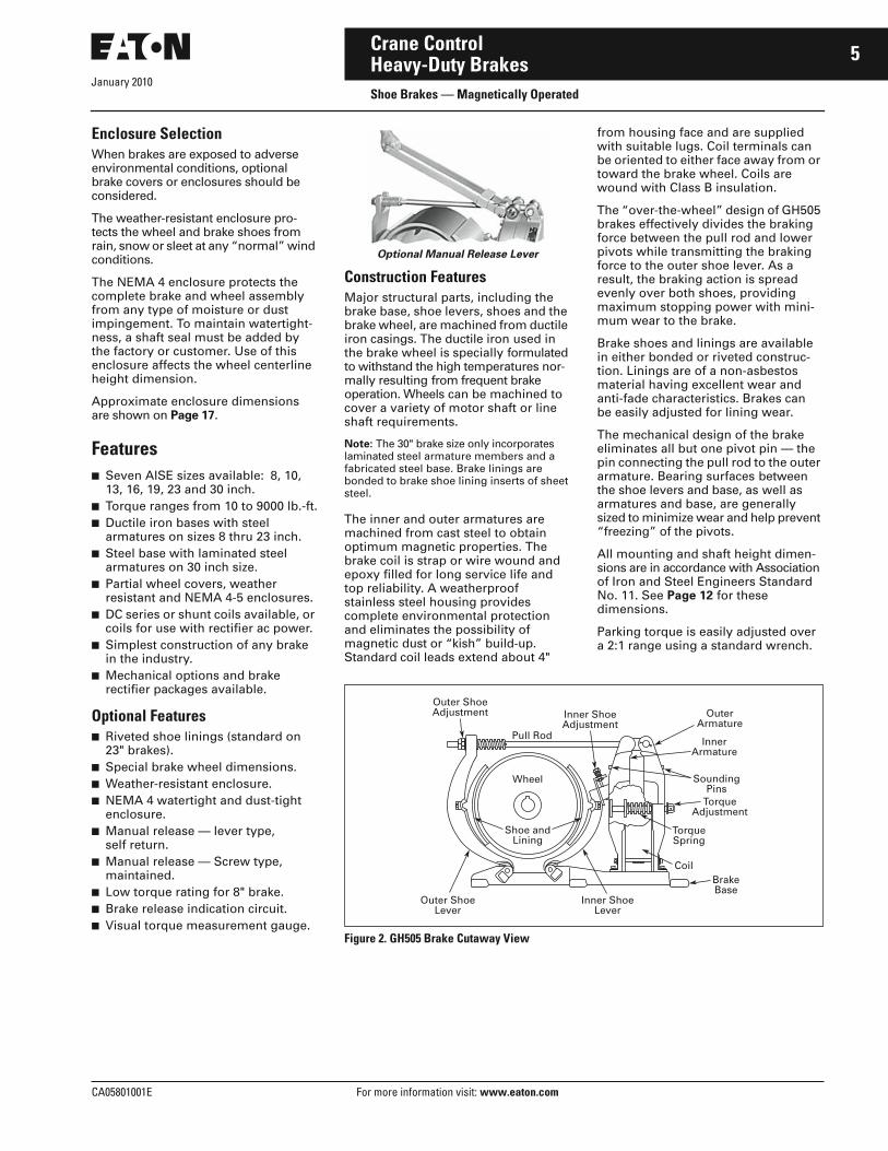
Optional Manual Release Lever
Construction FeaturesMajor structural parts, including the brake base, shoe levers, shoes and the brake wheel, are machined from ductile iron casings. The ductile iron used in the brake wheel is specially formulated to withstand the high temperatures nor-mally resulting from frequent brake operation. Wheels can be machined to cover a variety of motor shaft or line shaft requirements.
Note: The 30" brake size only incorporates laminated steel armature members and a fabricated steel base. Brake linings are bonded to brake shoe lining inserts of sheet steel.
The inner and outer armatures are machined from cast steel to obtain optimum magnetic properties. The brake coil is strap or wire wound and epoxy filled for long service life and top reliability. A weatherproof stainless steel housing provides complete environmental protection and eliminates the possibility of magnetic dust or “kish” build-up. Standard coil leads extend about 4"
from housing face and are supplied with suitable lugs. Coil terminals can be oriented to either face away from or toward the brake wheel. Coils are wound with Class B insulation.
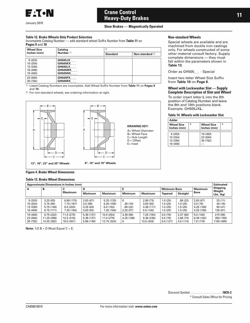
The “over-the-wheel” design of GH505 brakes effectively divides the braking force between the pull rod and lower pivots while transmitting the braking force to the outer shoe lever. As a result, the braking action is spread evenly over both shoes, providing maximum stopping power with mini-mum wear to the brake.
Brake shoes and linings are available in either bonded or riveted construc-tion. Linings are of a non-asbestos material having excellent wear and anti-fade characteristics. Brakes can be easily adjusted for lining wear.
The mechanical design of the brake eliminates all but one pivot pin — the pin connecting the pull rod to the outer armature. Bearing surfaces between the shoe levers and base, as well as armatures and base, are generally sized to minimize wear and help prevent “freezing” of the pivots.
All mounting and shaft height dimen-sions are in accordance with Association of Iron and Steel Engineers Standard No. 11. See Page 12 for these dimensions.
Parking torque is easily adjusted over a 2:1 range using a standard wrench.
Figure 2. GH505 Brake Cutaway View
BrakeBase
Coil
TorqueSpring
TorqueAdjustment
SoundingPins
InnerArmature
Inner ShoeAdjustment
Outer ShoeAdjustment Outer
ArmaturePull Rod
Wheel
Shoe andLining
Inner ShoeLever
Outer ShoeLever

January 2010
6
For more information visit: www.eaton.com CA05801001E
Crane ControlHeavy-Duty BrakesShoe Brakes — Magnetically Operated
Standards and Certifications■ CMAA 4.9.■ AISE No. 6, 11.■ NEMA STD. 2-220.■ NEMA ICS 2-220.21.■ ASTM 80-55-06.
Technical Data and Specifications■ Sizes:
❑ Available in 8, 10, 13, 16, 19, 23 and 30 inch
■ Mounting:❑ Designed for floor mounting❑ Dimensions per AISE Standard
No. 11■ Torque Ratings:
❑ 10 lb.-ft. through 9000 lb.-ft.❑ Equal stopping and holding torque
rating■ Operation:
❑ Electrically released, spring set❑ Brake sets in case of power failure
■ Torque Adjustment:❑ Brake mechanism adjustable over
a 2:1 torque range (except for low torque 8" brakes)
■ Ambient Temperature: 40∞C
Table 2. Specifications
� When brake is used with Eaton’s Cutler-Hammer Rectifier Panel, intermittent duty torque ratings may be used as continuous.
Common Motor DataTable 3. Series Wound dc Mill Motor Ratings
Table 4. AC Wound Rotor Motors
Maximum Torque (lb-ft) Brake SizeInches(mm)
Wheel Specifications
Series Wound Shunt Wound �
1/2 Hour 1 Hour Intermittent Continuous WR2
(lb.-ft.2)Maximumr/min.
100 200 55010002000
65 130 365 6501300
100 200 55010002000
75 150 400 7501500
8 (203)10 (254)13 (330)16 (406)19 (483)
1.1 3 12 36 70
50004000318025002110
40009000
26006000
40009000
30006750
23 (584)30 (762)
210880
17401340
MotorFrame Size
1/2 Hour Ratings 1 Hour Ratings
hp Torque RPM FLC hp Torque RPM FLC
602603604606608
10 13-1/2 19 33 45
80 115 180 340 500
675620560515470
44 57 77 129 175
7-1/2 10 15 25 35
50 70 120 230 320
800725650575525
31 41 59 95131
610612614616618
65100135200265
7701225173526303810
445430400400385
248 375 500 730 955
50 75100150200
525 830114017502560
500475460450410
184274360536712
802A802B802C803804
6-1/2 10 13-1/2 19 26
45 80 105 160 235
750675675620580
29 45 57 77 98
5 7-1/2 10 15 20
30 50 65 110 160
900800800725650
21 31 41 59 75
806808810812814816818
39 65 90135200265325
410 76010701690262534804740
500450440420400400360
145 246 335 500 730 9551140
30 50 70100150200250
275 500 7351110171023303000
575525500475460450410
112184260360533712900
Horse-power
Full Load Torque — ft.-lbs.
900 RPM 1200 RPM 1800 RPM
5 7-1/2 10 15 20
31 46 62 93124
23 35 46 69 92
1523314661
25 30 40 50 60
155185247309371
115138185221277
7692———
75100125150
464619770926
346461576—
————

January 2010
CA05801001E For more information visit: www.eaton.com
7Crane ControlHeavy-Duty BrakesShoe Brakes — Magnetically Operated
OptionsTable 5. Optional Features
Industrial Torque Rating (7th Digit)These magnetic shoe brakes are Type GH505 modified to provide higher maximum torque ratings. See Table 27 on Page 19 for product selection. They are designed primarily for use with adjustable voltage or adjustable frequency drive systems, operated by brake rectifier panels. Order brake rectifier panels from Page 13.
Table 6. GH505 Brake — Industrial Rating
� When brake is used with Eaton’s Cutler-Hammer Rectifier Panel, intermittent duty torque ratings may be used as continuous.
Soft Stop Feature (7th Digit)
Gradual Increase in Torque Application■ Reduces dangerous load swings on
overhead cranes.■ Reduces gear wear caused by sudden
stops of mechanical drive systems.
A Low-Cost Alternative to Hydraulic Brakes on Radio Controlled Cranes
Field Adjustable Full Torque Delay■ Simple adjustment requires no
additional parts.■ Up to 6-second delay fits most
applications.
Self-Contained System■ No hydraulic power assist package
needed.■ Maintenance-free design.
Enclosures (8th Digit)
Figure 3. Brake OrientationThis is an illustration of Left and Right Hand enclosures. Enclosures must be mounted against end bell of motor — no gasket is supplied. Specify diameter of shaft at point it enters enclosure. Enclosure will be drilled to fit motor when requested — bolt hole configuration must be supplied.
Option Description Ordering InstructionChange Catalog Number Listed in Product Selection Table on Page 19 as Noted Below
*Brake Size — Inches (mm)
8(203)
10(254)
13(330)
16(406)
19(483)
23(584)
30(763)
Mechanical
(7th digit ofCatalog NumberGH505AAA)
Riveted linings Change 7th Digit from A to BExample: GH505AAA to GH505ABA
N/A Std. N/A
Manual release (lever type) Change 7th Digit from A to CExample: GH505AAA to GH505ACA
N/A
Maintained manual release (screw type)
Change 7th Digit from A to DExample: GH505AAA to GH505ADA
N/A
Low torque 8" GH505 brake 10 lb-ft Change 7th Digit from A to GExample: GH505AAA to GH505AGA
Low torque 8" GH505 brake 25 lb-ft Change 7th Digit from A to HExample: GH505AAA to GH505AHA
Brake release indication circuit Change 7th Digit from A to JExample: GH505AAA to GH505AJA
N/A
Visual torque measurement gauge Change 7th Digit from A to KExample: GH505AAA to GH505AKA
N/A
Soft stop Change 7th Digit from A to LExample: GH505AAA to GH505ALA
N/A N/A N/A
Special — Supply completedescription
Change 7th Digit from A to SExample: GH505AAA to GH505ASA
Consult Factory
Enclosure
(8th digit ofCatalog NumberGH505AAA)
NEMA 4 Enclosure with options requiring engineering —Supply complete description
Change 8th Digit from A to SExample: GH505AAA to GH505AAS ■ Shaft seal■ Terminal box■ Space heater
N/AN/AN/A
Maximum Torque (lb.-ft.) � Brake SizeInches (mm)Intermittent Continuous
120 240 66012002400
90 180 495 9001800
8 (203)10 (254)13 (330)16 (406)19 (483)
4800 3600 23 (584)
Dimensions. . . . . . . . . . . . . . . . . . . . . . . Pages 16, 17Discount Symbol . . . . . . . . . . . . . . . . . . 18CD-2
* Consult Sales Office for Pricing
Motor
MotorWheelCoil
WheelCoil
Top View
Left Hand Right Hand

January 2010
8
For more information visit: www.eaton.com CA05801001E
Crane ControlHeavy-Duty BrakesShoe Brakes — Magnetically Operated
GH505 Brake Wheel for Straight Shaft with Keyway
Accessories
Brake WheelsThese brake wheels are manufactured in 7 AISE sizes from ductile iron con-forming to ASTM 80-55-06. Steel wheels are also available. Stocked wheels are set up for mounting on mill and industrial motor shafts. Wheels with a pilot bore are also available for the OEM market.
Wheel SelectionBrake wheel selection is dependent on the dimensions of the shaft on which it will be mounted and on the location of the motor end bell and mounting feet with relation to the brake. Most com-monly, these brake wheels are mounted on a motor shaft extension opposite the drive end shaft. Some-times the brake will be located on the high speed shaft between the motor and gear box. Occasionally there will be a high speed shaft extension on the opposite side of the gear box where the brake can be located.
For dc mill motors, where the brake is to be located on the motor shaft exten-sion opposite the drive end, standard wheel dimensions have been estab-lished (AISE Standard No. 11). On Pages 9 – 10, Table 11 lists brake wheels where a “Standard” wheel has been set up for various motor frames.
If wheel requirements do not match motor frame listing availability, then two alternatives are open:
1. Choose the “Universal” wheel, which is a partially finished wheel. This wheel has the maximum amount of hub length and a pilot bore. The customer must machine the hub to the required length, and the required bore and keyway dimensions.
2. Order a “Special” brake wheel with all machining completed by Eaton’s Cutler-Hammer. “C”, “D”, Bore, Taper (if required), and keyway dimensions must be spec-ified. See brake wheel dimension drawing, Figure 4 on Page 11 for maximum and minimum dimen-sions. Note that wheel dimensions will always be “Special” when a NEMA 4 enclosure is required.
Specifications■ Standards:
❑ CMAA 4.9, AISE No. 6, 11❑ ASTM 80-55-06❑ NEMA Standard 2-220❑ NEMA ICS 2-220.21
■ Sizes:❑ 8, 10, 13, 16, 19, 23 and 30 inch
■ Mounting:❑ Tapered or straight bore shafts❑ Keyed or pressure fit
■ Construction:❑ Ductile iron standard with an
option for steel■ Standard Wheels:
❑ For mill and industrial frame motors
Energy Dissipation and Absorption CapabilityEach brake has a maximum energy dissipation and energy absorption capability based on a 40∞C ambient temperature. Brake energy ratings are normally given in foot pounds per hour (ft.-lb./hr.) for repetitive brake operations or in foot pounds (ft.-lbs.) for one long stop as listed in Table 7.
Table 7. Energy Dissipation/Absorption
Table 8. Brake Wheel Inertias and Maximum Allowable Rotational Speeds
Table 9. Brake Wheel Catalog Numbering System
Table 10. Wheel Size Code Suffix
Brake SizeInches (mm)
Energy DissipationRepetitiveOperation (ft.-lb./hr.)
EnergyAbsorptionOne Long Stop (ft.-lbs.)
8 (203)10 (254)13 (330)16 (406)19 (482)
1,500,000 2,200,000 4,300,000 6,100,000 9,400,000
163,000236,000470,000678,000
1,040,000
23 (584)30 (762)
14,600,00021,200,000
1,625,0002,360,000
BrakeSize
WR2
(lb.-ft.2)Maximumr/min.
8 (203)10 (254)13 (330)16 (406)19 (482)
1.1 3 12 36 70
50004000318025002110
23 (584)30 (762)
210880
17401340
SizeInches (mm)
CodeNumber
SizeInches (mm)
CodeNumber
8 (203)10 (254)13 (330)16 (406)
JXKXLXMX
19 (483)23 (584)30 (762)
NXPXRX
G H 5 0 5 J X A 0 1
Base Catalog Number
GH505
Wheel Size
Table 10
Wheel Suffix
See Table 11

January 2010
CA05801001E For more information visit: www.eaton.com
9Crane ControlHeavy-Duty BrakesShoe Brakes — Magnetically Operated
Table 11. Brake Wheel Selection Table
� 400 - 600 - 800 ac motor frames all per AISE specifications. See Page 12 for dimensional compatibility.� See dimensional drawing, Figure 4 on Page 11.
Note: Dimensions shown are approximate and are not to be used for construction purposes.
Motor Frame � Approximate Dimensions in Inches (mm) BrakeWheelSuffixNo.
Wheel � Bore
AWheelDia.
BWheelFace
CHubLength
DOffset
EInset
Size Taper per ft. (mm per meter)
Keyway
8" Brake Wheel (203 mm)402 - 602 - 802AC1 - AC2 - AC4603 - 604 - 803 - 804AC8Universal
8 (203) 8 (203) 8 (203) 8 (203) 8 (203)
3.25 (82.6)3.25 (82.6)3.25 (82.6)3.25 (82.6)3.25 (82.6)
3 (76.2)3 (76.2)3.5 (88.9)4 (101.6)6.88 (174.6)
4 (101.6)4 (101.6)4 (101.6)4 (101.6)5.25 (133.4)
2.63 (66.7)2.63 (66.7)2.13 (54.0)1.63 (41.3)0
1.75 (44.4)1.75 (44.4)2 (50.8)2.50 (63.5) .75 NOM (19.0)
1.25 (104.2)1.25 (104.2)1.25 (104.2)1.25 (104.2)—
.50 x .25 (12.7 x 6.4)
.50 x .25 (12.7 x 6.4)
.50 x .25 (12.7 x 6.4)
.50 x .25 (12.7 x 6.4)—
A01A01A02A03A04
SW5 - 2W5MC20MC30MCS2 - MD402AEK1
8 (203) 8 (203) 8 (203) 8 (203) 8 (203)
3.25 (82.6)3.25 (82.6)3.25 (82.6)3.25 (82.6)3.25 (82.6)
3 (76.2)3.5 (88.9)4 (101.6)3 (76.2)3.5 (88.9)
4.5 (114.3)3 (76.2)3 (76.2)2.75 (69.9)3 (76.2)
3.13 (79.4)1.13 (28.6) .63 (15.9)1.38 (34.9)1.13 (28.6)
1.75 (44.4)2 (50.8)2.50 (63.5)1.75 (44.4)1.12-1.13 (28.5-28.6)
1.25 (104.2)1.22 (101.6)1.22 (101.6)1.25 (104.2)—
.50 x .25 (12.7 x 6.4)
.50 x .22 (12.7 x 5.5)
.63 x .25 (15.9 x 6.4)
.50 x .25 (12.7 x 6.4)
.31 x .13 (8.0 x 3.2)
A05A06A07A08A09
K2K3 - K41811 - 18122111 - 21122510 - 2511
8 (203) 8 (203) 8 (203) 8 (203) 8 (203)
3.25 (82.6)3.25 (82.6)3.25 (82.6)3.25 (82.6)3.25 (82.6)
4 (101.6)4 (101.6)2 (50.8)2.5 (63.5)2.5 (63.5)
3 (76.2)3 (76.2)3.25 (82.6)3.75 (95.3)3.75 (95.3)
.63 (15.9) .63 (15.9)2.88 (73.0)2.88 (73.0)2.88 (73.0)
1.37-1.38 (34.9-34.92)1.62-1.63 (41.25-41.28)1.12-1.13 (28.5-28.6)1.37-1.38 (34.90-34.92)1.62-1.63 (41.2-41.3)
—————
.38 x .13 (9.5 x 31.8)
.44 x .16 (11.1 x 4.0)
.25 x .13 (6.4 x 3.2)
.31 x .16 (8.0 x 4.0)
.38 x .19 (9.5 x 4.7)
A10A11A12A13A14
289 - 2810 - 2811327 - 328366367 - 368 - 369 - 3610
8 (203) 8 (203) 8 (203) 8 (203)
3.25 (82.6)3.25 (82.6)3.25 (82.6)3.25 (82.6)
2.75 (69.9)3 (76.2)3 (76.2)3.5 (88.9)
3.75 (95.3)4 (101.6)4 (101.6)4 (101.6)
2.63 (66.7)2.63 (66.7)2.63 (66.7)2.13 (54.0)
1.87-1.88 (47.6-47.63)2.12-2.13 (53.9-54.0)2.25 (57.12)2.25 (57.12)
————
.50 x .25 (12.7 x 6.4)
.50 x .25 (12.7 x 6.4)
.50 x .25 (12.7 x 6.4)
.50 x .25 (12.7 x 6.4)
A15A16A17A18
10" Brake Wheel (254 mm)602 - 802 - AC1 - AC2 - AC4603 - 604 - 803 - 804606 - 806 - AC8 - AC12608Universal
10 (254)10 (254)10 (254)10 (254)10 (254)
3.75 (95.3)3.75 (95.3)3.75 (95.3)3.75 (95.3)3.75 (95.3)
3 (76.2)3.5 (88.9)4 (101.6)4.5 (114.3)7.75 (196.9)
4.25 (108.0)4.25 (108.0)4.25 (108.0)4.25 (108.0)6.25 (158.8)
3.13 (79.4)2.63 (66.7)2.13 (54.6)1.63 (41.3) .38 (9.5)
1.75 (44.4)2 (50.8)2.50 (63.5)3 (76.2)1 NOM (25.4)
1.25 (104.2)1.25 (104.2)1.25 (104.2)1.25 (104.2)—
.50 x .25 (12.7 x 6.4)
.50 x .25 (12.7 x 6.4)
.50 x .25 (12.7 x 6.4)
.75 x .25 (19.1 x 6.4)—
B01B02B03B04B05
MD404AE - SW10MD404AE2 - MCS4K5BWMD103
10 (254)10 (254)10 (254)10 (254)10 (254)
3.75 (95.3)3.75 (95.3)3.75 (95.3)3.75 (95.3)3.75 (95.3)
3.5 (88.9)3.5 (88.9)4 (101.6)3.5 (88.9)4.75 (120.7)
2.88 (73.0)3.88 (98.4)3.13 (79.4)2.5 (63.5)3.25 (82.6)
1.25 (31.8)2.25 (57.2)1 (25.4) .88 (22.2) .38 (9.5)
2 (50.8)2 (50.8)1.87 (47.6)2.50 (63.5)2.50 (63.5)
1.25 (104.2)1.25 (104.2)—1.22 (101.6)1.25 (104.2)
.50 x .25 (12.7 x 6.4)
.50 x .25 (12.7 x 6.4)
.50 x .19 (12.7 x 4.8)
.63 x .19 (15.9 x 4.8)
.50 x .25 (12.7 x 6.4)
B06B07B08B09B10
—327 - 328366 - 367 - 368 - 369 - 3610408 - 409
10 (254)10 (254)10 (254)10 (254)
3.75 (95.3)3.75 (95.3)3.75 (95.3)3.75 (95.3)
3.5 (88.9)3 (76.2)3 (76.2)4.25 (108.0)
4.25 (108.0)4.25 (108.0)4 (101.6)4.25 (108.0)
2.63 (66.7)3.13 (79.4)2.88 (73.0)1.88 (47.6)
1 NOM (25.4)2.12-2.13 (53.9-54.0)2.25 (57.1)2.88 (73.0)
————
—.50 x .25 (12.7 x 6.4).50 x .25 (12.7 x 6.4).75 x .38 (19.1 x 9.5)
B11B12B13B14
13" Brake Wheel (330 mm)603 - 604 - 803 -804606 - 806 - AC8 - AC12608 - 808610 - 810 - AC18 - MC10612 - 812 - AC25 - AC30
13 (330)13 (330)13 (330)13 (330)13 (330)
5.75 (146.1)5.75 (146.1)5.75 (146.1)5.75 (146.1)5.75 (146.1)
3.5 (88.9)4 (101.6)4.5 (114.3)4.5 (114.3)5 (127.0)
5 (127.0)5 (127.0)5.38 (136.7)5.38 (136.7)5.38 (136.7)
4.38 (111.1)3.88 (98.4)3.75 (95.3)3.75 (95.3)3.25 (82.6)
2 (50.8)2.50 (63.5)3 (76.2)3.25 (82.5)3.62-3.63 (91.95-92.08)
1.25 (104.2)1.25 (104.2)1.25 (104.2)1.25 (104.2)1.25 (104.2)
.50 x .25 (12.7 x 6.4)
.50 x .25 (12.7 x 6.4)
.75 x .25 (19.1 x 6.4)
.75 x .25 (19.1 x 6.4)
.75 x .25 (19.1 x 6.4)
C01C02C03C04C05
614UniversalK6K7K8
13 (330)13 (330)13 (330)13 (330)13 (330)
5.75 (146.1)5.75 (146.1)5.75 (146.1)5.75 (146.1)5.75 (146.1)
5 (127.0)8 (203.2)4 (101.6)4 (101.6)4 (101.6)
5.38 (136.7)6 (152.4)4 (101.6)4 (101.6)4 (101.6)
3.25 (82.6) .88 (22.2)2.88 (73.0)2.88 (73.0)2.88 (73.0)
4.25 (107.9)1 NOM (25.4)2.12 (53.9)2.37 (60.3)2.62 (66.6)
1.25 (104.2)————
1 x .38 (25.4 x 9.5)—.50 x .19 (12.7 x 4.8).63 x .25 (15.9 x 6.4).63 x .28 (15.9 x 7.1)
C06C07C08C09C10
MC40 - MC50327 - 328366 - 367 - 368 - 369 - 3610408 - 409 - 4010506 - 507 - 508
13 (330)13 (330)13 (330)13 (330)13 (330)
5.75 (146.1)5.75 (146.1)5.75 (146.1)5.75 (146.1)5.75 (146.1)
4.5 (114.3)3.19 (81.0)4 (101.6)4.25 (108.0)5 (127.0)
3.19 (81.0)4.5 (114.3)5.5 (140.0)5 (127.0)4.25 (108.0)
1.56 (40.0)4.19 (106.3)4.38 (111.1)3.63 (92.1)2.13 (54.0)
3 (76.2)2.12-2.13 (53.9-54.0)2.25 (57.1)2.88 (73.0)3.62-3.63 (92.05-92.08)
1.22 (101.6)————
.63 x .28 (15.9 x 7.1)
.50 x .25 (12.7 x 6.4)
.50 x .25 (12.7 x 6.4)
.75 x .38 (19.1 x 9.5)
.88 x .44 (22.2 x 11.1)
C11C12C13C14C15

January 2010
10
For more information visit: www.eaton.com CA05801001E
Crane ControlHeavy-Duty BrakesShoe Brakes — Magnetically Operated
Table 11. Brake Wheel Selection Table (Continued)
� 400 - 600 - 800 ac motor frames all per AISE specifications. See Page 12 for dimensional compatibility.� See dimensional drawing, Figure 4 on Page 11.
Motor Frame � Approximate Dimensions in Inches (mm) BrakeWheelSuffixNo.
Wheel � Bore
AWheelDia.
BWheelFace
CHubLength
DOffset
EInset
Size Taper per ft.(mm permeter)
Keyway
16" Brake Wheel (406 mm)606 - 806 - AC8 - AC12608 - 808610 - 810 - AC18612 - 812 - AC25 - AC30614 - 814 - AC40 - AC50
16 (406)16 (406)16 (406)16 (406)16 (406)
6.75 (171.5) 6.75 (171.5) 6.75 (171.5) 6.75 (171.5) 6.75 (171.5)
4 (101.6) 4.5 (114.3) 4.5 (114.3) 5 (127.0) 5 (127.0)
6.5 (165.1) 6.5 (165.1 6.5 (165.1) 6.5 (165.1) 6.5 (165.1)
5.88 (149.2) 5.38 (136.5) 5.38 (136.5) 4.88 (123.8) 4.88 (123.8)
2.50 (63.5)3 (76.2)3.25 (82.5)3.62-3.63 (91.9-92.0)4.25 (107.9)
1.25 (104.2)1.25 (104.2)1.25 (104.2)1.25 (104.2)1.25 (104.2)
.50 x .25 (12.7 x 6.4) .75 x .25 (19.1 x 6.4) .75 x .25 (19.1 x 6.4) .75 x .25 (19.1 x 6.4)1 x .38 (25.4 x 9.5)
D01D02D03D04D05
616 - 816UniversalMS10 - MD410AE2SW50 - MD412AEMCS12 - MD412AE2
16 (406)16 (406)16 (406)16 (406)16 (406)
6.75 (171.5) 6.75 (171.5) 6.75 (171.5) 6.75 (171.5) 6.75 (171.5)
5.5 (140.0 8.38 (212.9) 4.5 (114.3) 5 (127.0) 5 (127.0)
6.5 (165.1) 7.25 (184.2) 7 (177.8) 4.25 (108.0) 7.25 (184.4)
4.38 (111.1) 2.25 (57.2) 5.88 (149.2) 2.63 (66.7) 5.63 (142.9)
4.62-4.63 (117.3-117.4)1.5 NOM (38.1)3.25 (82.5)3.62-3.63 (91.9-92.0)3.62-3.63 (91.9-92.0)
1.25 (104.2)—1.25 (104.2)1.25 (104.2)1.25 (104.2)
1.25 x .38 (31.8-9.5)— .75 x .25 (19.1 x 6.4) .75 x .25 (19.1 x 6.4) .75 x .25 (19.1 x 6.4)
D06D07D08D09D10
EW408 - 409 - 4010506 - 507 - 508587 - 588 - 589
16 (406)16 (406)16 (406)16 (406)
6.75 (171.5) 6.75 (171.5) 6.75 (171.5) 6.75 (171.5)
5 (127.0) 4.38 (111.3) 4 (101.6) 5 (127.0)
5 (127.0) 6.5 (165.1) 5 (127.0) 5 (127.0)
3.38 (85.7) 5.50 (139.6) 4.38 (111.1) 3.38 (85.7)
4 (101.6)2.88 (73.0)3.63 (92.0)4.13 (104.7)
1.219 (101.6)———
1 x .38 (25.4 x 9.5) .75 x .38 (19.1 x 9.5) .88 x .44 (22.2 x 11.1)1 x .50 (25.4 x 12.7)
D11D12D13D14
19" Brake Wheel (482 mm)608 - 808610 - 810 - AC18612 - 812 - AC25 - AC30614 - 814 - AC40 - AC50 - SW75SMCS14 - MD414AE2
19 (483)19 (483)19 (483)19 (483)
19 (483)
8.75 (222.3) 8.75 (222.3) 8.75 (222.3) 8.75 (222.3)
8.75 (222.3)
4.5 (114.3) 4.5 (114.3) 5 (127.0) 5 (127.0)
5 (127.0)
7.5 (190.5) 7.5 (190.5) 7.5 (190.5) 7.5 (190.5)
7.5 (190.5)
7.38 (187.3) 7.38 (187.3) 6.88 (174.6) 6.88 (174.6)
6.88 (174.6)
3 (76.2)3.25 (82.5)3.62-3.63 (91.9-92.0)4.25 (107.9)
4.25 (107.9)
1.25 (104.2)1.25 (104.2)1.25 (104.2)1.25 (104.2)
1.25 (104.2)
.75 x .25 (19.1 x 6.4) .75 x .25 (19.1 x 6.4) .75 x .25 (19.1 x 6.4)1 x .38 (25.4 x 9.5)1 x .38 (25.4 x 9.5)
E01E02E03E04
E04
616 - 816618 - 818620UniversalSW75 - MD414AE
19 (483)19 (483)19 (483)19 (483)19 (483)
8.75 (222.3) 8.75 (222.3) 8.75 (222.3) 8.75 (222.3) 8.75 (222.3)
5.5 (140.0) 6 (152.4) 6.75 (171.5)11 (279.4) 5 (127.0)
7.5 (190.5) 7.5 (190.5) 7.5 (190.5)10 (254.0) 4.5 (114.3)
6.38 (161.9) 5.88 (149.2) 5.13 (130.2) 3.38 (85.7) 3.88 (98.4)
4.62-4.63 (117.3-117.4)5 (127.0)5.87-5.88 (149.1-149.2)2.25 NOM (57.1)4.25 (107.9)
1.25 (104.2)1.25 (104.2)1.25 (104.2)—1.25 (104.2)
1.25 x .38 (31.8 x 9.5)1.25 x .50 (31.8 x 12.7)1.25 x .50 (31.8 x 12.7)—1 x .38 (25.4 x 9.5)
E05E06E07E08E09
23" Brake Wheel (584 mm)612 - 812 - AC25 - AC30614 - 814 - AC40 - AC50616 - 816618 - 818620 - 820
23 (584)23 (584)23 (584)23 (584)23 (584)
11.25 (285.8)11.25 (285.8)11.25 (285.8)11.25 (285.8)11.25 (285.8)
5 (127.0) 5 (127.0) 5.5 (140.0) 6 (152.4) 6.75 (171.5)
8.25 (210.0) 8.25 (210.0) 8.25 (210.0) 8.75 (222.3) 9.75 (247.7)
8.88 (225.4) 8.88 (225.4) 8.38 (212.7) 8.38 (212.7) 8.63 (219.1)
3.62-3.63 (91.9-92.0)4.25 (107.9)4.62-4.63 (117.3-117.4)5 (127.0)5.87-5.88 (149.1-149.2)
1.25 (104.2)1.25 (104.2)1.25 (104.2)1.25 (104.2)1.25 (104.2)
.75 x .25 (9.5 x 6.4)1 x .38 (25.4 x 9.5)1.25 x .38 (31.8 x 9.5)1.25 x .50 (31.8 x 12.7)1.5 x .75 (38.1 x 19.1)
F01F02F03F04F05
622 - 822624 - 824UniversalSW150 - MD418AE2 - MCS18
23 (584)23 (584)23 (584)23 (584)
11.25 (285.8)11.25 (285.8)11.25 (285.8)11.25 (285.8)
7.25 (184.2) 9.25 (235.0)12.5 (317.5) 8 (203.2)
9.75 (247.7) 9.75 (247.7)11 (279.4) 4.75 (120.7)
8.13 (206.4) 6.13 (155.6) 4.13 (104.8) 4.38 (111.1)
6.25 (158.7)7 (177.7)2.5 NOM (63.5)5 (127.0)
1.25 (104.2)1.25 (104.2)—1.25 (104.2)
1.5 x .75 (38.1 x 19.1)1.5 x .75 (38.1 x 19.1)—1.25 x .63 (31.8 x 15.9)
F06F07F08F09
30" Brake Wheel (762 mm)616 - 816618 - 818620 - 820622 - 822624 - 824
30 (762)30 (762)30 (762)30 (762)30 (762)
14.25 (362.0)14.25 (362.0)14.25 (362.0)14.25 (362.0)14.25 (362.0)
5.5 (140.0) 6 (152.4) 6.75 (171.5) 7.25 (184.2) 9.25 (235.0)
10.25 (260.4)10.25 (260.4)10.25 (260.4)10.75 (273.1)10.75 (273.1)
11.88 (301.6)11.38 (288.9)10.63 (269.9)10.63 (269.9) 8.63 (219.1)
4.62-4.63 (117.3-117.4)5 (127.0)5.87-5.88 (149.1-149.2)6.24-6.25 (158.5-158.7)7 (177.7)
1.25 (104.2)1.25 (104.2)1.25 (104.2)1.25 (104.2)1.25 (104.2)
1.25 x .38 (31.8 x 9.5)1.25 x .50 (31.8 x 12.7)1.5 x .75 (38.1 x 19.1)1.5 x .75 (38.1 x 19.1)1.5 x .75 (38.1 x 19.1)
G01G02G03G04G05
CA05801001E For more information visit: www.eaton.com
11Crane Control
January 2010Heavy-Duty BrakesShoe Brakes — Magnetically Operated
Table 12. Brake Wheels Only Product SelectionIncomplete Catalog Number — add standard wheel Suffix Number from Table 11 on Pages 9 and 10
� Listed Catalog Numbers are incomplete. Add Wheel Suffix Number from Table 11 on Pages 9 and 10.
� For non-standard wheels, see ordering information at right.
Figure 4. Brake Wheel Dimensions
Table 13. Brake Wheel Dimensions
Note: 1/2 B + D Must Equal C + E.
Wheel SizeInches (mm)
CatalogNumber �
*
Standard Non-standard �
8 (203) 10 (254) 13 (330) 16 (406) 19 (483)
GH505JX_ _ _GH505KX_ _ _GH505LX_ _ _GH505MX_ _ _GH505NX_ _ _
23 (584) 30 (762)
GH505PX_ _ _GH505RX_ _ _
AA
BB
EE
DC
8", 10" and 19" Wheels
DC
13", 16", 23" and 30" Wheels
DRAWING KEY:
A= Wheel DiameterB= Wheel FaceC= Hub LengthD = OffsetE= Inset
Approximate Dimensions in Inches (mm) EstimatedShippingWeightLbs. (kg)
A B CMaximum
D E Minimum Bore MaximumBoreMinimum Maximum Minimum Maximum Tapered Straight
8 (203)10 (254)13 (330)16 (406)
3.25 (83) 3.75 (95) 5.75 (146) 6.75 (171)
6.88 (175) 7.75 (197) 8.0 (203) 7.25 (184)
2.63 (67)3.5 (89)3.25 (83)3.63 (92)
5.25 (133) 6.25 (159) 6.0 (152) 7.25 (184)
0 .38 (10) .88 (22)2.25 (57)
2.88 (73) 3.63 (92) 4.38 (111) 5.5 (140)
1.0 (25)1.0 (25)1.0 (25)1.0 (25)
.88 (22)1.0 (25)1.0 (25)1.0 (25)
2.63 (67)3.0 (76)4.25 (108)4.25 (108)
25 (11) 40 (18) 90 (41) 135 (61)
19 (483)23 (584)30 (762)
8.75 (222)11.25 (286)14.25 (362)
11.0 (279)12.5 (318)18.0 (457)
5.38 (137)5.38 (137)5.88 (149)
10.0 (254)11.0 (279)12.75 (324)
3.38 (86)4.25 (108)0
7.25 (184) 9.38 (238)13.5 (343)
3.0 (76)3.0 (76)5.0 (127)
2.37 (60)2.88 (73)4.5 (114)
5.5 (140)6.38 (162)7.0 (178)
215 (98) 350 (159)1100 (499)
Non-standard WheelsSpecial wheels are available and are machined from ductile iron castings only. For wheels constructed of some other material consult factory. Supply complete dimensions — they must fall within the parameters shown in Table 13.
Order as GH505_ _ - Special
Insert two letter Wheel Size Suffix from Table 10 on Page 8.
Wheel with Lockwasher Slot — Supply Complete Description of Slot and WheelTo order insert letter L into the 8th position of Catalog Number and leave the 9th and 10th positions blank.Example: GH505JXL.
Table 14. Wheels with Lockwasher SlotAdder
Wheel SizeInches (mm)
* Wheel SizeInches (mm)
*
8 (203)10 (254)13 (330)16 (406)
19 (483)23 (584)30 (762)—
Discount Symbol . . . . . . . . . . . . . . . . . . . . . . . 18CD-2* Consult Sales Office for Pricing

January 2010
12
For more information visit: www.eaton.com CA05801001E
Crane ControlHeavy-Duty BrakesShoe Brakes — Magnetically Operated
Table 15. Brake Compatibility with 400, 600 and 800 Frame Mill Motors — Inches (mm)
Figure 5. “Z” Dimension Drawing Reference
Note: Per AISE Standard No. 11 and NEMA 2-220, horizontal and vertical mounting tolerances shall be ± .063 inch (1.59 mm).
Brake SizeWheelDiameter
Wheel RimWidthC
MotorFrameSize
HeightDifferenceA
1st Holeto BrakeCenterline Z
HubLengthD
HubExtensionE
KeyWidthF
BoreDiameterG
8 (203) 3.25 (83) 402403602802A802B
——— .63 (16) .63 (16)
8.25 (210) 9.0 (229) 8.25 (210) 8.25 (210) 8.25 (210)
3.0 (76)3.0 (76)3.5 (89)3.0 (76)3.0 (76)
2.38 (60)2.38 (60)2.38 (60)2.38 (60)2.38 (60)
.5 (12.7) .5 (12.7) .5 (12.7) .5 (12.7) .5 (12.7)
1.75 (44)2.0 (51)1.75 (44)1.75 (44)1.75 (44)
10 (254) 3.75 (95) 404406603604802C803
———— -.75 (-19) .13 (3.2)
9.75 (248) 9.75 (248) 9.25 (235) 9.75 (248) 8.50 (216) 9.25 (235)
3.5 (89)4.0 (102)3.5 (89)3.5 (89)3.0 (76)3.5 (89)
2.38 (60)2.38 (60)2.38 (60)2.38 (60)2.38 (60)2.38 (60)
.5 (12.7) .5 (12.7) .5 (12.7) .5 (12.7) .5 (12.7) .5 (12.7)
2.0 (51)2.5 (64)2.0 (51)2.0 (51)1.75 (44)2.0 (51)
13 (330) 5.75 (146) 408410606608804806
———— -.88 (-22.2) .13 (3.2)
11.0 (280)11.63 (295)10.50 (267)11.0 (280)10.50 (267)10.50 (267)
4.5 (114)4.5 (114)4.0 (102)4.5 (114)3.5 (89)4.0 (102)
2.50 (64)2.50 (64)2.13 (54)2.50 (64)2.13 (54)2.50 (64)
.75 (19) .75 (19) .50 (12.7) .75 (19) .50 (12.7) .50 (12.7)
3.0 (76)3.25 (83)2.5 (64)3.0 (76)2.0 (51)2.5 (64)
16 (406) 6.75 (171) 412610808
—— -.88 (-22.2)
13.25 (337)12.75 (324)12.13 (308)
5.0 (127)4.5 (114)4.5 (114)
3.13 (79)3.13 (79)3.13 (79)
.75 (19) .75 (19) .75 (19)
3.63 (92)3.25 (83)3.0 (76)
19 (483) 8.75 (222) 414416612614810812
———-1.0 (-25.4) .13 (3.2)
15.25 (387)16.50 (419)14.25 (362)15.25 (387)13.25 (337)14.25 (362)
5.0 (127)5.5 (140)5.0 (127)5.0 (127)4.5 (114)5.0 (127)
3.13 (79)3.13 (79)3.13 (79)3.13 (79)2.63 (67)3.13 (79)
1.0 (25.4)1.25 (32) .75 (19)1.0 (25.4) .75 (19) .75 (19)
4.25 (108)4.63 (117)3.63 (92)4.25 (108)3.25 (83)3.63 (92)
23 (584) 11.25 (286) 418616618814816
———-1.13 (-29) .13 (3.2)
17.25 (438)17.25 (438)17.25 (438)15.50 (394)17.25 (438)
5.5 (140)6.0 (152)6.0 (152)5.0 (127)5.5 (140)
3.13 (79)2.63 (67)3.13 (79)2.13 (54)2.63 (67)
1.25 (32)1.25 (32)1.25 (32)1.0 (25.4)1.25 (32)
5.0 (127)4.63 (117)5.0 (127)4.25 (108)4.63 (117)
CD
E
G
KeyWidth
F
A
Z
Bore Taper onDiameter 1.25 per Foot
(104 per Meter)
CL Brake

January 2010
CA05801001E For more information visit: www.eaton.com
13Crane ControlHeavy-Duty BrakesShoe Brakes — Magnetically Operated
Rectifier Panel for ac Operation of Brake
Rectifier PanelsThe universal brake rectifier panel is designed for application on Type GH505 brakes. It is sized to handle up to four 8 or 10 inch brakes, two 13 or 16 inch brakes, or one 19 or 23 inch brake. Resistor components are provided for any of these brake combinations. A brake coil protective circuit included in the design allows continuous duty brakes to be applied at intermittent duty torque ratings.
Specifications■ Input Voltage:
❑ 230 V or 460 Vac 3-Phase, 60 Hz■ Output Voltage:
❑ 208 Vdc■ Economized Voltage:
❑ Approximately 30 Vdc■ Maximum Number of Brakes:
❑ 4 – 8" or 10"❑ 2 – 13" or 16"❑ 1 – 19" and above
■ Operation:❑ DC rectifier with forcing circuit❑ Full voltage applied to coil for
pick-up, economized voltage applied for holding
■ Enclosures:❑ NEMA 1/NEMA 3R and NEMA 4
with resistor penthouse
Table 16. Rectifier Panel Selection Table — Wall Mounted
� All brakes must be used on the same motion or motor drive.
Table 17. Shunt Brake Coil Data for Brakes Used with GH515 Rectifier Panels
Brake SizeInches (mm)
MaximumQuantityBrakes �
NEMA 12 Enclosure
460 V Input * 230 V Input *
8 or 10(203 or 254)
124
GH515ED17-1GH515ED17-2GH515ED17-3
GH515ED20-1GH515ED20-2GH515ED20-3
13 or 16(330 or 406)
12
GH515ED17-4GH515ED17-5
GH515ED20-4GH515ED20-5
19 or 23(483 or 584)
1 GH515ED17-6 GH515ED20-6
30 (762) 1 GH515ED17-7 GH515ED20-7
Size Coil PartNo.
Coil Ohms20°C
Torquelb.-ft.
CoilVoltage
SeriesOhms
ReleaseAmps
SetAmps
ReleaseTimeSecs.
SetTimeSecs.
Max.CoilWatts
CoilSuffixNo.
8 9-872-18 44.4 100 29 350 4.69 .19 .22 .15 310 2164
10 9-871-7 44.6 200 29 350 4.67 .28 .25 .20 385 2264
13 9-875-7 29.1 550 30 225 7.15 .49 .30 .22 550 2364
16 9-890-1 24.5 1000 27 225 8.48 .50 .40 .25 710 2464
19 9-888-3 9.34 2000 23 100 22.30 1.36 .45 .30 1025 2564
23 9-889-1 11.0 4000 26 100 18.90 1.21 .50 .32 1400 2664
Dimensions. . . . . . . . . . . . . . . . . . . . . . . . . . . Page 14Discount Symbol . . . . . . . . . . . . . . . . . . . . . . 18CD-2
* Consult Sales Office for Pricing

January 2010
14
For more information visit: www.eaton.com CA05801001E
Crane ControlHeavy-Duty BrakesShoe Brakes — Magnetically Operated
Figure 6. Elementary Diagram� Connect per dotted line if CR is omitted (T1 and T2 to motor terminals)
(CR contact is mounted on motor controller).
Table 18. Approximate Dimensions and Shipping Weights
T.O. = Timed Opening
L2 or T2
L2
3A
CR
1BR
1BR
2BR
2BR 2BR 2BR
1RES
3B
3B
21 22 23
20T.O.
Rect.
25
26
1BRFU310A
Shunt Brake
1B1 1B2
1BR 1BR
FU410A
27 28
5
6
1BR
L1 460V AC
CT
H1
H3
H4
H2
230V AC
X1X3 X2
X4
1
On DelayNormally ClosedTimed OpeningSet for 1 Sec.
351 Ohms
24
(56) (55)
L1 or T1
�
Brake RectifierPanel Number
Dimensions in Inches (mm) Ship. Wt.Lbs. (kg)A B C D E F G H
GH515ED17-1GH515ED20-1
20.00 (508)20.00 (508)
20.00 (508)20.00 (508)
14.00 (356)14.00 (356)
9.00 (228)9.00 (228)
14.00 (356)14.00 (356)
10.00 (254)10.00 (254)
10.00 (254)10.00 (254)
21.25 (540)21.25 (540)
130 (59)130 (59)
GH515ED17-2GH515ED20-2
20.00 (508)20.00 (508)
20.00 (508)20.00 (508)
14.00 (356)14.00 (356)
5.00 (127)5.00 (127)
14.00 (356)14.00 (356)
10.00 (254)10.00 (254)
10.00 (254)10.00 (254)
21.25 (540)21.25 (540)
130 (59)130 (59)
GH515ED17-3GH515ED20-3
20.00 (508)20.00 (508)
20.00 (508)20.00 (508)
14.00 (356)14.00 (356)
5.00 (127)5.00 (127)
14.00 (356)14.00 (356)
10.00 (254)10.00 (254)
10.00 (254)10.00 (254)
21.25 (540)21.25 (540)
130 (59)130 (59)
GH515ED17-4GH515ED20-4
20.00 (508)20.00 (508)
20.00 (508)20.00 (508)
14.00 (356)14.00 (356)
5.00 (127)5.00 (127)
14.00 (356)14.00 (356)
10.00 (254)10.00 (254)
10.00 (254)10.00 (254)
21.25 (540)21.25 (540)
130 (59)130 (59)
GH515ED17-5GH515ED20-5
20.00 (508)20.00 (508)
20.00 (508)20.00 (508)
14.00 (356)14.00 (356)
9.00 (228)9.00 (228)
14.00 (356)14.00 (356)
10.00 (254)10.00 (254)
10.00 (254)10.00 (254)
21.25 (540)21.25 (540)
130 (59)130 (59)
GH505ED17-6GH515ED20-6
20.00 (508)20.00 (508)
20.00 (508)20.00 (508)
14.00 (356)14.00 (356)
5.00 (127)5.00 (127)
14.00 (356)14.00 (356)
10.00 (254)10.00 (254)
10.00 (254)10.00 (254)
21.25 (540)21.25 (540)
130 (59)130 (59)
Figure 7. Approximate Dimensions
C
ED
A
CB
1.01 F
H
G
(25.6)

January 2010
CA05801001E For more information visit: www.eaton.com
15Crane ControlHeavy-Duty BrakesShoe Brakes — Magnetically Operated
Renewal PartsTable 19. Replacement Brake Shoes and Linings Selection Chart
� Quantity 2 required for each brake.� Quantity listed is per shoe.
Note: For prices, refer to Eaton’s parts distributor or consult factory.
Table 20. Cross-Reference to New Coils
Description Brake Size
8 Inch 10 Inch 13 Inch 16 Inch 19 Inch 23 Inch 30 Inch
Part Number Part Number Part Number Part Number Part Number Part Number Part Number
Shoe Lining � 48-1818 48-1818-2 48-1818-3 48-1818-4 48-1818-5 48-1818-6 48-1278-3
Shoe with Bonded Lining � 48-1267-4 48-1268-4 48-603-7 48-554-7 48-1971 — —
Shoe with Riveted Lining � 48-1462-3 48-1463-3 48-603-8 48-554-8 — 48-633-4 48-1277-2
Rivet (Quantity) � 13-4762 (8) 13-4762 (8) 13-4762 (12) 13-4762 (18) — 13-4762 (30) —
OldPart Number
BrakeSize
CatalogSuffix Number
ReplacementPart Number
9-827-19-827-29-827-39-827-49-827-6
1616161616
140214011405—1400
9-884-19-884-109-884-59-884-49-884-11
9-827-79-827-99-827-109-827-11
16161616
14041404——
9-884-99-884-99-884-49-884-3
9-840-19-840-29-840-39-840-49-840-5
1313131313
13021305130213011304
9-883-109-883-69-883-109-883-79-883-2
9-840-69-840-79-841-19-841-29-841-3
1313191919
—130315071512—
9-883-49-883-19-885-259-885-69-885-19
9-841-49-841-59-841-69-841-89-841-9
1919191919
15031507150315051504
9-885-179-885-279-885-179-885-169-885-24
9-841-109-841-119-841-129-841-139-841-14
1919191919
—15111508—1501
9-885-219-885-189-885-89-885-109-885-23
9-841-159-841-169-844-29-844-39-844-4
1919101010
15011502121012071208
9-885-239-885-209-2628-39-2628-19-2628-2
9-845-19-845-29-845-39-845-49-845-5
2323232323
16041605—1601—
9-886-59-886-89-886-149-886-109-886-13
9-845-69-845-79-845-99-845-109-845-11
2323232323
——16021603—
9-886-149-886-139-886-19-886-49-886-13
9-845-129-845-139-847-19-847-29-847-3
2323 8 8 8
1602160121632164—
9-886-19-886-109-872-119-872-189-872-12
9-847-49-847-59-847-69-847-79-847-8
8 8 8 8 8
11081111——1102
9-872-49-872-79-872-169-872-19-872-10
9-847-99-847-109-847-119-847-129-847-13
8 8 8 8 8
11121107—1113—
9-872-89-872-39-872-129-872-139-872-21
9-847-149-847-159-847-17
8 8 8
———
9-872-149-872-229-872-1
OldPart Number
BrakeSize
CatalogSuffix Number
ReplacementPart Number
9-864-19-864-29-864-39-864-49-864-6
1010101010
2263226412041205—
9-871-89-871-79-871-49-871-59-871-1
9-864-79-864-89-864-99-864-109-864-11
1010101010
—12031202——
9-871-99-871-39-871-29-871-129-871-14
9-864-129-864-13
1010
——
9-871-139-871-15
9-865-19-865-29-865-49-865-59-865-6
1313131313
23632364——1308
9-875-129-875-79-875-99-875-159-875-1
9-865-79-865-89-865-99-865-10
13131313
13091308—1307
9-875-29-875-19-875-49-875-8
9-865-129-865-139-865-149-865-169-865-17
1313131313
—————
9-875-179-875-189-875-169-875-199-875-14
9-866-19-866-29-866-39-867-19-867-2
1616161919
24632464—2563—
9-890-29-890-19-890-39-888-19-888-3
9-867-39-867-69-868-19-868-29-868-3
1919232323
—256426632664—
9-888-29-888-39-889-59-889-19-889-2
9-868-49-882-19-885-15
23 819
—11141506
9-889-49-872-209-885-25
9-1641-19-1641-29-1641-39-1641-49-1641-5
3030303030
17041705170617031702
9-1641-89-1641-79-1641-69-1641-99-1641-10
9-1955-19-1956-29-1960-19-1960-2
10132323
1240130116041605
9-2628-39-883-79-886-59-886-8
9-1961-19-1961-29-1961-39-1964-19-1964-2
303030 8 8
17041705170621632164
9-1641-89-1641-79-1641-69-872-119-872-18
9-1967-19-1967-29-1969-19-1969-2
10101313
2263226423632364
9-871-89-871-79-875-129-875-7
9-1971-19-1971-29-1973-19-1973-2
16161919
1402140115051503
9-884-19-884-109-885-169-885-17

January 2010
16
For more information visit: www.eaton.com CA05801001E
Crane ControlHeavy-Duty BrakesShoe Brakes — Magnetically Operated
Sample Product SpecificationMagnetic brakes shall be heavy-duty, mill type, with mount-ing dimensions, wheel diameter, and torque ratings in accor-dance with AISE Standard No. 11 and NEMA Standards, Section ICS 2-220.21.
Brakes shall be spring set and electrically released, by means of a dc coil, encapsulated in a weather-resistant housing. Major brake structural parts (except 30" size) shall be ductile iron or steel castings. Brake shoes shall be fitted with either bonded or riveted non-asbestos linings. There shall be provisions for a simple check for lining wear and easy adjustment means. Torque shall be easily adjustable over a 2:1 torque range.
Brakes used with an ac power system will be provided with a separate brake rectifier panel designed to match the brake coil requirements.
Dimensions
Open Type
Figure 8. Brake Dimensions
Table 21. Approximate Dimensions in Inches (mm) and Shipping Weights — GH505 Brakes — Open Type
� Does not include wheel.
(4) N Holes
The Fifth Hole Support and MountingShould Be Used for Charging Machines.
Ingot Buggies, Pit Crane Trolleys, andSimilar Severe Shock Applications. It
Must Be Used at All Times on 30" Brakes.
R
U
V
LM
BBQP
A
NN Slot
Keyway
TS
H
V
A BB H L M N NN P Q R S T U V Ship. Wt. �
Lbs. (kg)
8(203)
16.0(406)
7.0(178)
2.88(73)
3.69(94)
.69(17)
.75 x .88(19 x 22)
3.25(83)
3.88(98)
16.81(427)
6.5(165)
15.38(391)
5.0(127)
13.63(346)
153 (69)
10(254)
17.63(448)
8.38(213)
3.13(79)
3.94(100)
.69(17)
.75 x .875(19 x 22)
4.0(102)
4.88(124)
18.44(468)
8.0(203)
17.0(432)
5.63(143)
15.75(400)
223 (101)
13(330)
20.31(516)
9.88(251)
4.5(114)
5.5(140)
.81(21)
.88 x 1.0(22 x 25)
5.75(146)
6.75(171)
21.25(540)
9.88(251)
19.88(505)
6.75(171)
19(483)
420 (191)
16(406)
22.63(575)
12.13(308)
5.38(137)
6.5(165)
1.06(27)
1.13 x 1.38(29 x 35)
7.5(191)
8.75(222)
23.88(606)
12.25(311)
21.88(556)
7.75(197)
22.75(578)
565 (257)
19(483)
26.38(670)
13.25(337)
6.5(165)
7.88(200)
1.06(27)
1.13 x 1.38(29 x 35)
9.25(235)
10.63(270)
27.63(702)
14.5(368)
26.5(673)
9.25(235)
25.63(651)
1005 (456)
23(584)
30.25(768)
15.88(403)
8.0(203)
9.5(241)
1.31(33)
1.38 x 1.63(35 x 41)
11.75(298)
13.25(337)
31.75(806)
18.13(460)
30.38(772)
10.5(267)
30.38(772)
1480 (672)
30(762)
42.5(1080)
20.75(527)
9.5(241)
11.25(286)
1.56(40)
1.56 x 1.56(40 x 40)
15.0(381)
17.0(432)
44.5(1130)
24.25(616)
42.63(1083)
10.75(273)
40.38(1026)
3000 (1362)
Brake Wheel Dimensions. . . . . . . . . . . . . . . Page 11
January 2010
CA05801001E For more information visit: www.eaton.com
17Crane ControlHeavy-Duty BrakesShoe Brakes — Magnetically Operated
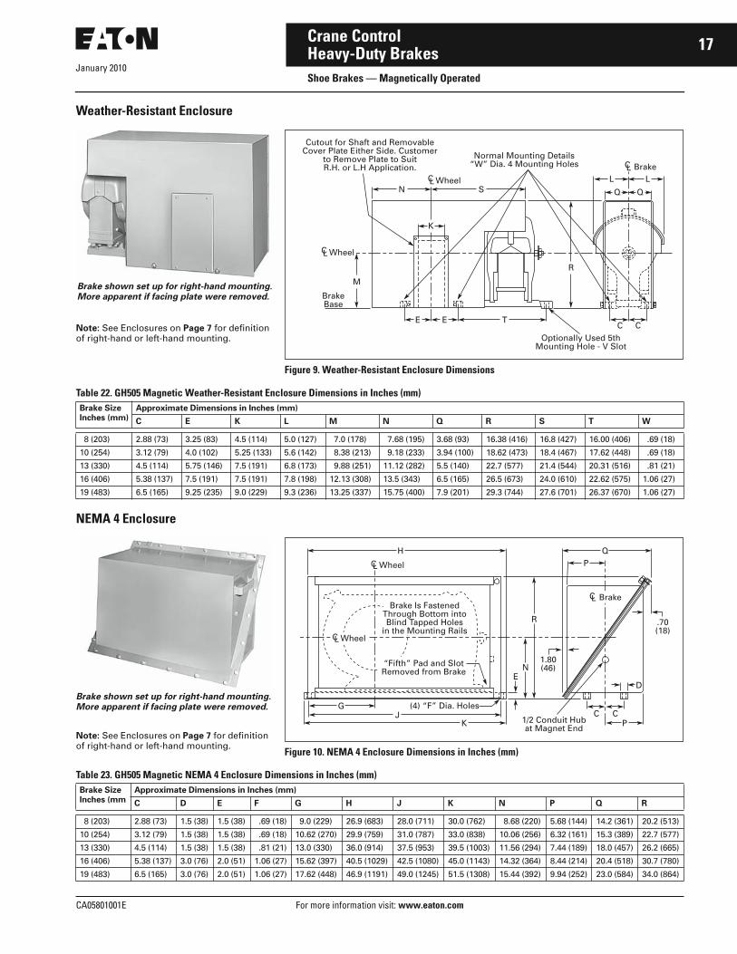
Weather-Resistant Enclosure
Table 22. GH505 Magnetic Weather-Resistant Enclosure Dimensions in Inches (mm)
NEMA 4 Enclosure
Table 23. GH505 Magnetic NEMA 4 Enclosure Dimensions in Inches (mm)
Brake SizeInches (mm)
Approximate Dimensions in Inches (mm)
C E K L M N Q R S T W
8 (203) 2.88 (73) 3.25 (83) 4.5 (114) 5.0 (127) 7.0 (178) 7.68 (195) 3.68 (93) 16.38 (416) 16.8 (427) 16.00 (406) .69 (18)
10 (254) 3.12 (79) 4.0 (102) 5.25 (133) 5.6 (142) 8.38 (213) 9.18 (233) 3.94 (100) 18.62 (473) 18.4 (467) 17.62 (448) .69 (18)
13 (330) 4.5 (114) 5.75 (146) 7.5 (191) 6.8 (173) 9.88 (251) 11.12 (282) 5.5 (140) 22.7 (577) 21.4 (544) 20.31 (516) .81 (21)
16 (406) 5.38 (137) 7.5 (191) 7.5 (191) 7.8 (198) 12.13 (308) 13.5 (343) 6.5 (165) 26.5 (673) 24.0 (610) 22.62 (575) 1.06 (27)
19 (483) 6.5 (165) 9.25 (235) 9.0 (229) 9.3 (236) 13.25 (337) 15.75 (400) 7.9 (201) 29.3 (744) 27.6 (701) 26.37 (670) 1.06 (27)
Brake SizeInches (mm
Approximate Dimensions in Inches (mm)
C D E F G H J K N P Q R
8 (203) 2.88 (73) 1.5 (38) 1.5 (38) .69 (18) 9.0 (229) 26.9 (683) 28.0 (711) 30.0 (762) 8.68 (220) 5.68 (144) 14.2 (361) 20.2 (513)
10 (254) 3.12 (79) 1.5 (38) 1.5 (38) .69 (18) 10.62 (270) 29.9 (759) 31.0 (787) 33.0 (838) 10.06 (256) 6.32 (161) 15.3 (389) 22.7 (577)
13 (330) 4.5 (114) 1.5 (38) 1.5 (38) .81 (21) 13.0 (330) 36.0 (914) 37.5 (953) 39.5 (1003) 11.56 (294) 7.44 (189) 18.0 (457) 26.2 (665)
16 (406) 5.38 (137) 3.0 (76) 2.0 (51) 1.06 (27) 15.62 (397) 40.5 (1029) 42.5 (1080) 45.0 (1143) 14.32 (364) 8.44 (214) 20.4 (518) 30.7 (780)
19 (483) 6.5 (165) 3.0 (76) 2.0 (51) 1.06 (27) 17.62 (448) 46.9 (1191) 49.0 (1245) 51.5 (1308) 15.44 (392) 9.94 (252) 23.0 (584) 34.0 (864)
R
M
SN
EC
Q Q
C
L L
E T
K
BrakeBase
CL Wheel
CL Wheel
CL BrakeNormal Mounting Details
“W” Dia. 4 Mounting Holes
Optionally Used 5thMounting Hole - V Slot
Cutout for Shaft and RemovableCover Plate Either Side. Customer
to Remove Plate to SuitR.H. or L.H Application.
Brake shown set up for right-hand mounting. More apparent if facing plate were removed.
Note: See Enclosures on Page 7 for definition of right-hand or left-hand mounting.
Figure 9. Weather-Resistant Enclosure Dimensions
N
R
E
KJ
G
HP
C C
D
P
Q
1.80(46)
.70(18)
1/2 Conduit Hubat Magnet End
(4) “F” Dia. Holes
Brake Is FastenedThrough Bottom intoBlind Tapped Holes
in the Mounting Rails
“Fifth” Pad and SlotRemoved from Brake
CL Wheel
CL Wheel
CL Brake
Brake shown set up for right-hand mounting. More apparent if facing plate were removed.
Figure 10. NEMA 4 Enclosure Dimensions in Inches (mm)
Note: See Enclosures on Page 7 for definition of right-hand or left-hand mounting.

January 2010
18
For more information visit: www.eaton.com CA05801001E
Crane ControlHeavy-Duty BrakesShoe Brakes — Magnetically Operated
Circuit Diagrams
Figure 11. Elementary Diagrams for Standard Brake Circuits
230 Vdc Power
Series Brake
M
BR
1 Res.
Series FieldStartingResistor
Armature SeriesBrake Coil
BR
230 Vdc Control
Shunt Brake
SeriesResistor
ShuntBrake Coil
BR BR
TR
200 – 250 Vdc
Shunt Brake with Protective Circuit
Catalog Number SelectionTable 24. Brake Catalog Numbering System
G H 5 0 5 A A A 1 1 0 7 A 0 1
Base CatalogNumber
GH505 = Magnetic
Enclosure Options
A = Open type
C = Weather-resistant
D = NEMA 4 L.H. w/o shaft seal
E = NEMA 4 R.H. w/o shaft seal
S = NEMA 4 w/shaft seal (consult factory)
Coil Suffix
See Pages 20 – 21.
Mechanical Options
A = No mechanical options
B = Riveted linings (standard on 19" and 23" brakes)
C = Manual release (lever type)
D = Maintained manual release (screw type)
N = Industrial torque rating (see Page 7)
S = Special, modified per customer application
Brake Size
ABCD
====
8"10"13"16"
EFG
===
19"23"30"
Wheel Suffix
N = No Wheel
_ _ _ _ = Select WheelSuffix Codefrom Table 11.

January 2010
CA05801001E For more information visit: www.eaton.com
19Crane ControlHeavy-Duty BrakesShoe Brakes — Magnetically Operated
Product SelectionWhen Ordering Specify■ Base Catalog Number of standard brake from table below.
Add coil and brake wheel suffixes from appropriate tables on Pages 9, 10, 20 and 21.
■ For special mechanical, enclosure, coil or wheel modifica-tions, see Optional Feature listing on Page 7. Change the completed Catalog Number of the standard brake to describe the feature required.
■ If required modification is not listed, order standard brake and supply complete description of change(s).
■ Rectifier panels for brake operation from an ac power supply are listed on Page 13.
GH505 Magnetic Shoe Brake
Table 25. GH505 Magnetic Brakes — Add Coil and Wheel Suffix Numbers
� Listed Catalog Numbers are incomplete. Add Coil Suffix Number from Pages 20, 21 and Wheel Suffix Number (if required) from Pages 9 and 10.� Prices shown for brakes with wheel include standard wheels only. These are identified in the Brake Wheel Selection Tables on Pages 9 and 10.
See Page 11 for non-standard wheel prices.� Prices listed do NOT include separate required series for shunt coils. For price addition, refer to Table 30 on Page 21.
Table 26. NEMA 4 GH505 Magnetic Brakes — Add Coil Suffix
� Prices listed do NOT include separate required series for shunt coils. For price addition, refer to Table 30 on Page 21.
� Listed Catalog Numbers are incomplete. Add Coil Suffix Number from Pages 20, 21.
� For NEMA 4 enclosure with shaft seal, see ordering instructions under Options, Page 7. NEMA 4 enclosed brakes normally require special wheel.
� See Figure 3 on Page 7 for illustration of Left and Right Hand enclosures. Enclosure must be mounted against end bell of motor — no gasket is supplied. Specify diameter of shaft at point it enters enclosure. Enclosure will be drilled to fit motor when requested — bolt hole configuration must be supplied.
Table 27. Industrial Torque Rating Brakes — Add Coil Suffix
Order brake wheels separately from Page 11. Incomplete Catalog Number — add Shunt Coil Suffix Number from
Table 30 on Page 21.
BrakeSizeinches(mm)
Wheel Open Type Weather Resistant
CatalogNumber �
* �� CatalogNumber �
* ��
8(203)
w/ Wheelw/o Wheel
GH505AAA_ _ _ _ _ _ _GH505AAA_ _ _ _N
GH505AAC_ _ _ _ _ _ _GH505AAC_ _ _ _N
10(254)
w/ Wheelw/o Wheel
GH505BAA_ _ _ _ _ _ _GH505BAA_ _ _ _N
GH505BAC_ _ _ _ _ _ _GH505BAC_ _ _ _N
13(330)
w/ Wheelw/o Wheel
GH505CAA_ _ _ _ _ _ _GH505CAA_ _ _ _N
GH505CAC_ _ _ _ _ _ _GH505CAC_ _ _ _N
16(406)
w/ Wheelw/o Wheel
GH505DAA_ _ _ _ _ _ _GH505DAA_ _ _ _N
GH505DAC_ _ _ _ _ _ _GH505DAC_ _ _ _N
19(483)
w/ Wheelw/o Wheel
GH505EAA_ _ _ _ _ _ _GH505EAA_ _ _ _N
GH505EAC_ _ _ _ _ _ _GH505EAC_ _ _ _N
23(584)
w/ Wheelw/o Wheel
GH505FAA_ _ _ _ _ _ _GH505FAA_ _ _ _N
GH505FAC_ _ _ _ _ _ _GH505FAC_ _ _ _N
30(762)
w/ Wheelw/o Wheel
GH505GAA_ _ _ _ _ _ _GH505GAA_ _ _ _N
GH505GAC_ _ _ _ _ _ _GH505GAC_ _ _ _N
BrakeSizeinches(mm)
Wheel NEMA 4 Watertight & Dust-Tight �
Left Handw/o Shaft Seal �
Right Handw/o Shaft Seal �
* �
CatalogNumber �
CatalogNumber �
8(203)
w/ Wheelw/o Wheel
—GH505AAD_ _ _ _N
—GH505AAE_ _ _ _N
—
10(254)
w/ Wheelw/o Wheel
—GH505BAD_ _ _ _N
—GH505BAE_ _ _ _N
—
13(330)
w/ Wheelw/o Wheel
—GH505CAD_ _ _ _N
—GH505CAE_ _ _ _N
—
16(406)
w/ Wheelw/o Wheel
—GH505DAD_ _ _ _N
—GH505DAE_ _ _ _N
—
19(483)
w/ Wheelw/o Wheel
—GH505EAD_ _ _ _N
—GH505EAE_ _ _ _N
—
23(584)
w/ Wheelw/o Wheel
—GH505FAD_ _ _ _N
—GH505FAE_ _ _ _N
—
30(762)
w/ Wheelw/o Wheel
—GH505GAD_ _ _ _N
—GH505GAE_ _ _ _N
Brake SizeInches (mm)
Open Type
Catalog Number *
8 (203)10 (254)13 (330)16 (406)19 (483)23 (584)
GH505ANA_ _ _ _NGH505BNA_ _ _ _NGH505CNA_ _ _ _NGH505DNA_ _ _ _NGH505ENA_ _ _ _NGH505FNA_ _ _ _N
Coil SelectionPages 20, 21Brake Wheel Selection . . . . . . . . . . . . Pages 9, 10Discount Symbol . . . . . . . . . . . . . . . . . . 18CD-2
* Consult Sales Office for Pricing

January 2010
20
For more information visit: www.eaton.com CA05801001E
Crane ControlHeavy-Duty BrakesShoe Brakes — Magnetically Operated
Coil SelectionIf series wound dc mill motors are being used at their full nameplate current rating, Standard coils may be chosen from Table 28. If not, use Table 29.
Table 28. GH505 Series Coil Selection Chart — Standard Mill Motors
Table 29. GH505 Series Coil Selection Chart — By Load Current. Select so that full load current falls near middle of coil ampere range listed below. �
� Coil selection chart is for 230 V motors only. For other armature volt-ages, order special engineered coil and provide complete description. Coil Selection should be based on actual full load current and duty cycle of the motor rather than rated full load motor current.
FrameSize
Coil Suffix Number FrameSize
Coil Suffix Number
Brake Size — Inches (mm) Brake Size — Inches (mm)
8(203)
10(254)
13(330)
16(406)
19(483)
23(584)
30(762)
8(203)
10(254)
13(330)
16(406)
19(483)
23(584)
30(762)
402, 802A602, 802B603, 802C604, 803804
1107110911101112—
——120412061207
———13111302
—————
—————
—————
—————
612614, 812616, 814618, 816818
—————
—————
—————
—————
1505150715081509—
—160116031605—
————1703
606806608610, 808810
—————
120812091210——
1302130413041305—
14001400140114021403
———15041505
—————
—————
620622———
—————
—————
—————
—————
—————
—————
17041705———
BrakeSizeInches(mm)
Ampere Range CoilSuffixNumber
1/2 Hour Duty 1 Hour Duty
Minimum Maximum Minimum Maximum
8(203)
7 8.5 10.5 13 16
8.75 10.85 13.4 17 21
6 7.2 8.8 10.5 13.5
7.2 9 11.1 14 17
11011102110311041105
18 22 28 37 41
24 31 39 49 59
15 19 24 31 35
20 25 32 41 49
11061107110811091110
55 62 88150173
77 91122169185
46 52 74127146
64 75101139154
11111112111311141115
10(254)
20 28 35 45 58
28 38 47 60 77
16 23 29 37 49
25.5 34 42 54 70
12011202120312041205
66 88107
91113137
55 73 7
82103125
120612111212
124147
152185
101121
125154
12091210
13(330)
19 29 35 44 61
26 40 50 64 87
15 23 28 35 48
20 32 39 49 67
13071308130913101311
71 84 92 93
102135149129
56 66 72 7
79107117102
1312130113021313
BrakeSizeInches(mm)
Ampere Range CoilSuffixNumber
1/2 Hour Duty 1 Hour Duty
Minimum Maximum Minimum Maximum
13(Cont.)
123 135 193 336
205 229 336 564
96 105 150 262
162 181 264 445
1303130413051306
16(406)
123 148 162 258 345
165 244 268 432 578
92 120 131 210 280
132 193 213 343 458
14001401140214031404
235 395 191 314 1405
19(483)
102 127 178 225 250
138 173 252 326 361
84 105 146 185 205
111 139 202 262 289
15011502150315041511
260 338 375 450 520
375 490 550 660 777
214 277 308 371 427
302 394 448 530 622
15051506150715121508
750 965
11081400
618 793
8901128
15091510
23(584)
390 459 600 651 866
508 618 804 8681200
311 366 479 518 693
415 503 656 710 98
16011602160316041605
975 1360 778 1110 1606
30(762)
450 720 95812801643
615 935126016882180
360 531 709 9341214
470 717 96512931675
17011702170317041705
2300 3040 1700 2325 1706

January 2010
CA05801001E For more information visit: www.eaton.com
21Crane ControlHeavy-Duty BrakesShoe Brakes — Magnetically Operated
Table 30. GH505 Shunt Coil Selection Chart
� Series resistor is shipped in package attached to brake pull rod. Coils shipped without series resistor still require a series resistor in the circuit. The resistor MUST be supplied separately.
� For use with GH515 Rectifier Panel. Required resistor is located on and supplied with panel.
Note: For multiple brake systems, shunt brake coils are normally connected in parallel.
Table 31. GH505 Shunt Coil Resistance and Series Resistor Resistance
� Series resistor is shipped in package attached to brake pull rod. Coils shipped without series resistor still require a series resistor in the circuit. The resistor MUST be supplied separately.
� Series resistor control on separate brake rectifier. Contact Eaton for data when using GH515 rectifier panel.
BrakeSizeInches(mm)
LineVoltage
DutyCycle
With Series Resistor � Shipped Without Resistor �
BrakeSizeInches(mm)
LineVoltage
DutyCycle
With Series Resistor � Shipped Without Resistor �
CoilSuffixNumber
Adder*
CoilSuffixNumber
CoilSuffixNumber
Adder*
CoilSuffixNumber
8(203)
230 Vdc230 Vdc208 Vdc
IntermittentContinuousContinuous
21602162—
21612163 2164 �
16(406)
230 Vdc230 Vdc208 Vdc
IntermittentContinuousContinuous
24602462—
2461 24632464 �
10(254)
230 Vdc230 Vdc208 Vdc
IntermittentContinuousContinuous
22602262—
2261 2263 2264 �
19(483)
230 Vdc230 Vdc208 Vdc
IntermittentContinuousContinuous
25602562—
2561 2563 2564 �
13(330)
230 Vdc230 Vdc208 Vdc
IntermittentContinuousContinuous
23602362—
2361 2363 2364 �
23(584)
230 Vdc230 Vdc208 Vdc
IntermittentContinuousContinuous
26602662—
2661 2663 2664 �
30(762)
230 Vdc230 Vdc
IntermittentContinuous
27602762
27612763
CoilSuffixNumbers
CoilOhms
Series � ResistorOhms
TotalPower(Watts)
CoilSuffixNumbers
CoilOhms
Series � ResistorOhms
TotalPower(Watts)
21602162216422602262
44.4110.6 44.4 44.6102.2
78.0104.0 � 66.0 94.0
432247—478270
24622464256025622564
38.024.514.934.3 9.34
52.0�
21.029.0�
588—1474 836—
22642360236223642460
44.6 29.1 45.4 29.1 24.5
� 52.0 78.0 � 38.0
—652429—846
26602662266427602762
11.028.811.0 3.71 3.71
16.038.0�
9.017.6
1959 792—41622482
Discount Symbol . . . . . . . . . . . . . . . . . . . . . 18CD-2* Consult Sales Office for Pricing

January 2010
22
For more information visit: www.eaton.com CA05801001E
Crane ControlMaster and Limit SwitchesType F Master Switches — GH101
Product DescriptionThe Type F Master Switch is a cam operated, vertical type control circuit master. Straight line operation of the handle is achieved by means of a right angle bevel gear assembly. A maximum of 16 circuits and 6 speed positions are available in the step type master. A maximum of 6 circuits and a directly coupled potentiometer are available in the stepless master. Master switches are furnished with a positive mechani-cal stop located in the operating head of the switch. Masters are available both as open devices for benchboard mounting, and NEMA 3 enclosed for wall or floor mounting. The joystick master provides for concurrent operation of two control motions with one operating handle.
Mounting brackets are screwed to the bottom of the case for floor type mount-ing. Tapped holes are provided on the rear of the case which may be used for relocating the mounting brackets for wall mounting.
Features■ Floor mounted, desk mounted and
benchboard mounted versions.■ 6, 12 and 16 circuit versions.■ Spring return, off-point latch speed
point detents, and handle pushbutton options available.
■ Contacts rated 1.1 amperes inductive break at 250 Vdc, 10 amperes continuous.
■ Stepless and step-type versions.■ Single motion and joystick.
Technical Data andSpecifications■ Voltage: 250 V maximum.■ Current Rating:
❑ Make:– dc, 30 amperes
❑ Carry: – dc, 10 amperes– 115 Vac, 30 ampere make —
8 ampere break ❑ Interrupt:
– 115 Vdc inductive, 2.2 amperes– 230 Vdc inductive, 1.1 amperes
■ Stepless Units: ❑ Potentiometer or resolver unit
■ Circuits: ❑ 6, 12 or 16 circuit versions available
■ Manual Operation.
Standards and Certifications■ OSHA 1910.179.■ NEMA ICS3-442.14.■ NEMA ICS2-125.21.02.■ CMAA 70-5.7.
Renewal PartsTable 32. Type F Master Switch
Note: For prices, refer to Eaton’s parts distributor or call factory.
Dimensions
Figure 12. Approximate Dimensions in Inches (mm)
Note: Dimensions shown are approximate and are not to be used for construction purposes.
Table 33. Approximate Dimensions and Shipping Weights
Note: The installation and use of Cutler-Hammer products by Eaton Corporation should be in accordance with the provisions of the U.S. National Electrical Code and/or other local codes or industry standards that are pertinent to the particular end use. Installation or use not in accordance with these codes and standards could be hazardous to personnel and/or equipment.
Part Description Part Number
Contact Block, CompleteStationary ContactMovable ContactContact Kit
86-260123-343923-33446-202
Type NumberofCircuits
Dimensions in Inches (mm) Ship.Wt.Lbs. (kg)
WideA
HighB
DeepC
Mounting F
D E
NEMA 3 EnclosedSingleMotion
61216
6.88 (175)6.88 (175)6.88 (175)
15 (381)21.25 (540)25.5 (648)
6.62 (168)6.62 (168)6.62 (168)
6.0 (152)6.0 (152)6.0 (152)
4.62 (117)4.62 (117)4.62 (117)
7.94 (202)7.92 (202)7.94 (202)
34 (15)38 (17)44 (20)
Joystick 12 12 (305) 21.25 (540) 6.62 (168) 11 (279) 4.62(117) 12.5 (318) 50 (23)
Open Type (Benchboard Mounting)OpenMotion
612
5 (127)5 (127)
11.5 (292)18 (457)
6.62 (168)6.62 (168)
4 (102)4 (102)
5.75 (146)5.75 (146)
7.94 (202)7.94 (202)
23 (10)25 (11)
Joystick 12 8 (203) 18 (457) 10 (254) 7.25 (184) 9 (229) 12.5 (318) 40 (18)
D
E
C
B
F
B
NEMA 3 EnclosedOpen Type (Benchboard Mounting)
F
A AD
CE

January 2010
CA05801001E For more information visit: www.eaton.com
23Crane ControlMaster and Limit SwitchesType F Master Switches — GH101
Catalog Number Selection — Standard Assembled SwitchesTable 34. Assembled Switches Catalog Numbering System
Product Selection — Standard Switches for Use with Cutler-Hammer Control PanelsWhen Ordering Specify■ Complete GH101 Catalog Number,
OR■ Complete description of master
switch, including each contact closure sequence, OR
■ Reference to previous Cutler-Hammer Catalog Number or factory serial number.
Table 35. Type GH101 Master Switches for Present Standard Eaton’s Cutler-Hammer Crane Controllers �
� All Catalog Number listings are for right-hand mounting — NEMA Std. ICS3-442.14. For left-hand mounting, change 10th digit from “1” to “2”. Example: GH101BA332A11.
G H 1 0 1 B A 3 3 1 A 1 1
Parent Number
GH101 = Type F Master Switch
Controls
A = StepB = Stepless
OFF Latch/Spring Return
1 = Without OFF Latch or Spring Return2 = With Spring Return3 = With OFF Latch4 = With Spring Return and OFF Latch
Control Panel Type
11 = GH11, 1411113 = GH1314 = GH14A15 = GH15, 1411517 = GH1718 = GH18A22 = GH23, 14122RP,
GH27, 14122DL60 = 1416066 = 1416687 = GH86, GH8788 = GH88
Legend Plate
A = FORWARD/REVERSEB = HOIST/LOWERC = Custom
Mounting
1 = Right-hand2 = Left-hand
No. of Speed Points
3 = 34 = 45 = 58 = Stepless
Size
A = 12 Circuits, NEMA 3 EnclosedB = 6 Circuits, NEMA 3 EnclosedC = 12 Circuits OpenD = 6 Circuits OpenE = 16 Circuits Enclosed
Application NEMA 3 Enclosed
Controller Type Number
Number of Speeds EachDirection
With OFF Latch With Spring Return Without OFF Latch or Spring Return
Catalog Number
* Catalog Number
* Catalog Number
*
GH11, 14111 5 GH101AA351A11 GH101AA251A11 GH101AA151A11
GH15, 14115 5 GH101AA351B15 GH101AA251B15 GH101AA151B15
GH23, 14122RP 34
GH101BA331A22GH101BA341A22
GH101BA231A22GH101BA241A22
GH101BA131A22GH101BA141A22
GH27, 14122DL 34
GH101BA331B22GH101AA341B22
GH101BA231B22GH101AA241B22
GH101BA131B22GH101AA141B22
14160 35
GH101BA331A60GH101AA351A60
GH101BA231A60GH101AA251A60
GH101BA131A60GH101AA151A60
14166 5 GH101AA351B66 GH101AA251B66 GH101AA151B66
GH13 5 GH101AA351A13 GH101AA251A13 GH101AA151A13
GH17 5 GH101AA351B17 GH101AA251B17 GH101AA151B17
GH86, GH87 Stepless GH101AB381A87 GH101AB281A87 GH101AB181A87
GH88 Stepless GH101AB381B88 GH101AB281B88 GH101AB181B88
GH14A 5 GH101AA351A14 GH101AA251A14 GH101AA151A14
GH18A 5 GH101AA351B18 GH101AA251B18 GH101AA151B18
Discount Symbol . . . . . . . . . . . . . . . . . . . . . . . 18CD-2* Consult Sales Office for Pricing

January 2010
24
For more information visit: www.eaton.com CA05801001E
Crane ControlMaster and Limit SwitchesType F Master Switches — GH101
Catalog Number Selection — Custom SwitchesTable 36. Custom Switches Catalog Numbering System
Note: Include description of contact closure sequence. Use worksheet on Page 26 to describe contact sequence.
Product Selection — Custom SwitchesWhen Ordering Specify■ Basic master switch Catalog
Number and price from Table 37.■ Off latch or spring return from
Table 38. Add Code Suffix Number to basic Catalog Number.
■ Number of speeds from Table 39. Add Code Suffix Number to Catalog Number.
■ Select right- or left-hand mounting from Table 40. Add Code Suffix Number to composite Catalog Number.
■ Provide description of contact closure sequence as detailed in Table 41. Use Worksheet on Page 26 to describe contact sequence, or provide closure sequence diagram.
■ Determine legend plate required. See Table 42. Add Code Suffix Letter to basic Catalog Number.
■ See example on Page 27.
G H 1 0 1 B A 2 4 1 A
Basic Master Switch
Table 37
Legend
Table 42
Mounting
Table 40
OFF Latch/Spring Return
Table 38
Number of Speeds
Table 39
Open Type Single Motion Stepless Master Switch, 6 Circuit, Left-Hand Mounting
NEMA 3 EnclosedStep-Type SingleMotion Master Switch, 12 Circuits, Left-Hand Mounting
NEMA 3 Enclosed Joystick Master Switch, Stepless,6 Circuits for Each Motion

January 2010
CA05801001E For more information visit: www.eaton.com
25Crane ControlMaster and Limit SwitchesType F Master Switches — GH101
Table 37. Basic Master Switch
� All stepless master switches require 12 circuit frame. They include a standard 4 watt, 1500 ohm potentiometer. Induction units are also available. Consult factory for details.
Table 38. OFF Latch or Spring Return Selection �
� OFF position latch and left-hand mounting not available for joystick masters.
Table 39. Number of Speeds (Each Direction)
Table 40. Right- or Left-Hand Mounting ��
� OFF position latch and left-hand mounting not available for joystick masters.
� Mounting refers to which side of the operating head the lever is on. Left-hand mounting (shown above) has the lever closest to the left-hand side of the operator, i.e., on the right side of the head.
Table 41. Contact Closure Sequence
Table 42. Legend Plate Requirement
Construction MaximumNumber ofCircuits perMotion
Master Switch Type
Step Type Stepless Type �
Single Motion Joystick Single Motion Joystick
Standard With Handle Pushbutton
Standard With Handle Pushbutton
CatalogNumber
* CatalogNumber
* CatalogNumber
* CatalogNumber
* CatalogNumber
* CatalogNumber
*
OpenType
612
GH101DAGH101CA
GH101DCGH101CC
GH101DEGH101CE
—GH101CB
—GH101CD
—GH101CF
NEMA 3Enclosed
61216
GH101BAGH101AAGH101EA
GH101BCGH101ACGH101EC
GH101BEGH101AE—
—GH101AB—
—GH101AD—
—GH101AF—
Description CodeSuffix
Adder*
Without OFF latch, without spring returnWith spring returnWith OFF position latchWith spring return and OFF position latchWith reduced tension spring return
12345
Description CodeSuffix
Adder*
3 Speed4 Speed5 Speed6 Speed
3456
SteplessStepless with float optionNon-symmetrical (specify)
890
Description CodeSuffix
Adder*
Right-hand mountingLeft-hand mounting
12
Provide description of contact closure sequencing using Worksheet on Page 26 or advise reference to previous Cutler-Hammer Catalog Number or factory serial number.Example: GH101DA331A with 5 circuit units per diagram sketch at right.
Adder per circuit *
Description CodeSuffix
Adder*
FORWARD — REVERSEHOIST — LOWERAll others (specify on order)
ABC
Discount Symbol . . . . . . . . . . . . . . . . . . . . . . . 18CD-2* Consult Sales Office for Pricing
RevFwd

January 2010
26
For more information visit: www.eaton.com CA05801001E
Crane ControlMaster and Limit SwitchesType F Master Switches — GH101
Diagram Worksheet for Special Master Switches
Figure 13. Contact Closure Sequence Diagram Worksheet
5 4 3
Reverse
Hoist
Forward
Lower
2 1 1/2 1/2Off
Shaft End
1 2 3 4 5
(Circle One) (Circle One)
Cross OutSpeed Points
Not Used
Designate Required Wire Numbers at Each Circuitand Draw in Connections
X = Contact ClosedPlace “X” at Intersection with Each Speed
Point Where Contact Is to Be Closed.

CA05801001E For more information visit: www.eaton.com
27Crane Control
January 2010Master and Limit SwitchesType F Master Switches — GH101
Custom Switch Ordering ExampleTo order/price a custom Type F Master Switch like the one illustrated at the right — NEMA 3 enclosed, 6 circuit spring return switch with cam arrangement as shown in Table 41 on Page 25 — proceed as follows: (Referenced tables will be found on Page 25.)
Table 43. Custom Switch Ordering Example
Cross-Reference to Previous ProductsTable 44. Type F Master Switch Cross-Reference to Previous Products
Description CatalogNumber
*
1. Select basic switch from Table 37 — NEMA 3 enclosed, 6 circuit maximum, step type.
GH101BA
2. For spring return, add Suffix Code 2 from Table 38 to Catalog Number. GH101BA2
3. The contact sequence chart in Table 41 shows 3 speed points. Table 39 says that 3 speed points adds a Suffix Code 3 to the Catalog Number. The cams are symmetrical, 3 speeds in each direction.
GH101BA23
4. For right-hand operation (lever closest to operator’s right-hand), add Suffix Code 1 from Table 40.
GH101BA231
5. Per sketch in Table 41, switch uses a total of 5 contacts.
6. For FORWARD-REVERSE legend plate on top of enclosure (per sketch in Table 41), add Suffix Code A from Table 42 to Catalog Number.
GH101BA231A
Total
With Off Latch With Spring Return
Old New Old New
14951H11714951H12314951H12714951H12914951H131
GH101BA331A11GH101AA351A66GH101BA331A22GH101BA341A22GH101BA331B22
14951W1314951W1414951W1514951W1614951W17
GH101BA231A11GH101BA231A60GH101AA251A11GH101AA251A60GH101AA251B15
14951H13314951H13914951H14114951H17714951H181
GH101AA341B22GH101AA351B15GH101AA351A11GH101BA341B22GH101AA351B15
14951W1814951W2914951W3014951W3114951W32
GH101AA251A66GH101BA231B22GH101BA241B22GH101BA231A22GH101BA241A22
14951H18514951W1014951W11
GH101AA351A11GH101BA331A60GH101AA351A60
———
———
NEMA 3 Enclosed6 Circuit Step Type SwitchRight-Hand Operation
Discount Symbol . . . . . . . . . . . . . . . . . . . . . . . 18CD-2* Consult Sales Office for Pricing

January 2010
28
For more information visit: www.eaton.com CA05801001E
Crane ControlMaster and Limit SwitchesType C Master Switches — GH103
Product DescriptionThe Type C Master Switch is a cam operated control circuit master switch, six circuit maximum, which can be supplied a NEMA 1 sheet steel enclo-sure, or open type for benchboard mounting. Cams are directly driven by the operating handle. Switches with “universal” cams have “daisy petal” twist offs which can be broken away to obtain any desired operating sequence.
Standards and Certifications■ NEMA ICS3-442.14.■ CMAA 70-5.7.
Technical Data andSpecifications■ Voltage: 250 V maximum.■ Current Rating:
❑ .6 amperes at 250 Vdc, inductive❑ 5.0 amperes at 115 Vac
■ Circuits: ❑ 3 or 6 circuit maximum versions
■ Manual Operation.■ Speed Points:
❑ Up to 3 in each direction, cams field adjustable
OptionsTable 45. Options
Renewal PartsTable 46. Type C Master Switch
� For 6-circuit switches order qty. 2.
Note: For prices, refer to Eaton’s parts distributor or call factory.
Dimensions
Figure 14. Approximate Dimensions in Inches (mm)
Table 47. Approximate Dimensions and Shipping Weights
Diagrams
Figure 15. Contact Closure Sequence
Description Adder*
Spring return to OFF positionNon-reverse operationThree-speed reversing on six-circuitswitch
Special cam arrangementSpecial legend plate
Description Part Number
3-Circuit Contact Block � 83-530-3
NumberofCircuits
Dimensions in Inches (mm) Ship. Wt.Lbs. (kg)Wide
AHighB
DeepC
Mounting HandleFD E
Open Type36
4.19 (106)4.19 (106)
4.5 (114)4.5 (114)
4.5 (114)7.13 (181)
2.13 (54)2.13 (54)
——
2.56 (65)2.56 (65)
6 (2.7)8 (3.6)
NEMA 1 Enclosed3 or 6 5.47 (139) 8 (203) 4.78 (121) 2.75 (70) 4.38 (111) 2.63 (67) 11 (5)
1.25(32)
D
Mtg. Plate
B
C.52 (13) Dia. 2Holes for Mtg. F
Open Type
A
.11 (3) Min..19 (5) Max.
C
NEMA 1Enclosed
A
DF
.28 (7) Dia. (4) Mtg. HolesB
E
1 23 45 67 89 1011 12
1 234567
1 234
1 2465
31 2
34
1 234
1 2
ShaftEnd
ShaftEnd
ShaftEnd
ShaftEnd
ShaftEnd
ShaftEnd
ShaftEnd
A31 A32 A33 A34(Daisy Petal)
A35
A36 A37(Daisy Petal)
34 5
8
Discount Symbol . . . . . . . . . . . . . . . . . . . . . . . 18CD-2* Consult Sales Office for Pricing

CA05801001E For more information visit: www.eaton.com
29Crane Control
January 2010Master and Limit SwitchesType C Master Switches — GH103
Product SelectionWhen Ordering Specify■ Complete GH101 Catalog Number,
OR■ Complete description of master
switch, including each contact closure sequence, OR
■ Reference to previous Cutler-Hammer Catalog Number or factory serial number.
Table 48. Type C Master Switch Product Selection
Note: See contact closure sequence in Figure 15 on Page 28.
Number of Speeds EachDirection
Numberof Circuits
Open Type Enclosed
Catalog Number
* NEMA 1
Catalog Number
*
11222 (NR)
33333
GH103HB111A31GH103HB111A32GH103HB121A33GH103HB121A34GH103HB141A35
GH103DA111A31GH103DA111A32GH103DA121A33GH103DA121A34GH103DA141A35
22
66
GH103GB121A36GH103GB121A37
GH103CA121A36GH103CA121A37
Cross-Reference to Previous ProductsTable 49. Type C Master Switch Cross-Reference to Previous ProductsOpen Type
Old New
14951N314951N414951N514951N614951N7
GH103HB111A31GH103HB111A32GH103HB121A33GH103HB121A34GH103HB141C35
14951N814951N9
GH103GB121A36GH103GB121A37
Discount Symbol . . . . . . . . . . . . . . . . . . . . . . . 18CD-2* Consult Sales Office for Pricing

January 2010
30
For more information visit: www.eaton.com CA05801001E
Crane ControlMaster and Limit SwitchesCrane Power Limit Switches
Product DescriptionThese Crane Power Limit Switches are mounted on the crane trolley to prevent overtravel of the crane hook when hoisting.
They act as a power circuit disconnect for the hoisting motor. On dc applica-tions, a resistor is required with the limit switch to provide dynamic braking.
Features■ Single and duplex types.■ 50 hp to 500 hp range, ac or
dc operation.■ Double-pole, double-throw power
circuit contacts.■ NEMA 3 enclosed.■ Power resistors and lever options
available.
Standards and Certifications■ OSHA 1910.179, 306.■ AISE Standard No. 6.■ NEMA ICS3-445, CMAA 70-5.9.
Technical Data andSpecifications■ Types:
❑ Single or Duplex❑ 2- or 3-pole❑ double throw
■ Mounting:❑ Trolley deck mounting❑ Hanging horizontal mounting❑ Left-hand vertical mounting ❑ Right-hand vertical mounting
■ Ratings:❑ 5 to 500 hp at 230 Vdc❑ 5 to 400 hp at 460 Vac
■ Operation: ❑ Counterweighted lever is tripped
by cable motion and reset by reset weight. Reset weight is actu-ated by hoist block mechanism
■ Contacts: ❑ Cadmium copper alloy contacts
with positive wiping action oper-ate in an arc chute. Contacts are interchangeable with Type C80 dc contactor contacts
■ Enclosure: ❑ NEMA 3R weather-resistant
enclosure with U-shaped cover for easy access to mechanism
OptionsTable 50. Options
� To add electrical interlock, change 8th digit of Catalog Number from “A” to “B.” Example: GH120SAB1111.
Type P50 Power Limit Switch with Lever, Cable, Fittings and Weight
Type P375, Single
Description Adder *
P50Single
P100 P200 P375, P500
Single Duplex Single Duplex Single Duplex
Electrical Interlock �
Three-Pole Limit Switch N/A N/A N/A N/A N/A N/A
Table 51. Maximum Horsepower Ratings
Renewal PartsTable 52. Power Limit Switches
Note: For prices, refer to Eaton’s parts distributor or call factory.
LimitSwitchType
Maximum hp Crane Rating
dc ac
230 V 550 V 230 V 460 V
P50P100P200P375P500
50100200375500
50100200600—
50100200——
100200400——
Incomplete DeviceCatalog Number
Contact KitPart Number
Blowout Assembly (dc)Part Number
GH120GH121GH122GH123GH126
6-2076-207-26-207-36-207-46-207-5
62-812-562-47962-109-1462-45062-450
Discount Symbol . . . . . . . . . . . . . . . . . . . . . . . 18CD-2* Consult Sales Office for Pricing

January 2010
CA05801001E For more information visit: www.eaton.com
31Crane ControlMaster and Limit SwitchesCrane Power Limit Switches
Dimensions
Figure 16. Approximate Dimensions
Table 53. Limit Switches
Table 54. Reset Weights
Figure 17. Reset Weight Outline
Type Approximate Dimensions in Inches (mm) Ship. Wt. Lbs. (kg)
WideA
HighB
DeepC
Mounting OverallF
Mtg. HoleG
Limit SwitchOnly
Lever ResetWeightD E
P50 SingleP100 SingleP100 DuplexP200 SingleP200 Duplex
17.5 (445)20.75 (527)20.75 (527)26.0 (660)28.56 (726)
10.75 (273)12.25 (311)12.25 (311)15.38 (391)15.38 (391)
18.5 (470)22.06 (560)30.56 (776)26.38 (670)38.88 (987)
14.0 (356)16.5 (419)16.5 (419)24.0 (610)24.0 (610)
12.25 (311)15.75 (400)24.25 (616)18.5 (470)30.5 (775)
15.13 (384)18.0 (457)18.0 (457)26.25 (667)26.25 (667)
.63 (16)
.75 (19)
.75 (19)
.94 (24)
.94 (24)
83 (38)148 (67)217 (98)315 (143)481 (218)
42 (19) 79 (36) 87 (39)103 (47)131 (59)
46 (21) 80 (36) 97 (44)108 (49)176 (80)
P375 SingleP375 DuplexP500 SingleP500 Duplex
38.63 (981)38.63 (981)38.63 (981)38.63 (981)
24.25 (616)24.25 (616)24.25 (616)24.25 (616)
42.13 (1070)60.13 (1527)42.13 (1070)60.13 (1527)
36.25 (921)36.25 (921)36.25 (921)36.25 (921)
23.25 (591)41.25 (1048)23.25 (591)41.25 (1048)
38.25 (972)38.25 (972)38.25 (972)38.25 (972)
.94 (24)
.94 (24)
.94 (24)
.94 (24)
1028 (466)1467 (665)1028 (466)1467 (665)
230 (104)383 (174)230 (104)383 (174)
240 (109)506 (230)240 (109)506 (230)
A C
B Optional Mountingof Lever
D
Stop
Run
FE
G
ResetWeightLbs. (kg)
Used withSwitchType
Approximate Dimensions in Inches (mm)
FigureNumber
WidthB (Dia.)
LengthA
46 (21) 80 (36) 97 (44)108 (49)176 (80)240 (109)240 (109)
P50 SingleP100 SingleP100 DuplexP200 SingleP200 DuplexP375 SingleP500 Single
1111122
5 (127) 6 (152) 6 (152) 6 (152) 7 (178) 8 (203) 8 (203)
10.5 (267)12.5 (318)14.62 (372)16.0 (407)19.25 (489)15.5 (394)15.5 (394)
506 (230)506 (230)
P375 DuplexP500 Duplex
22
10.5 (267)10.5 (267)
19.5 (495)19.5 (495)
ALength
BDia.
ALength
B WidthSquare
Figure 1 Figure 2

January 2010
32
For more information visit: www.eaton.com CA05801001E
Crane ControlMaster and Limit SwitchesCrane Power Limit Switches
Mounting
Figure 18. Alternate Mounting Positions — P50, P100 and P200 Only — P375 and P500 Horizontal Floor Mounting Only
Catalog Number SelectionTable 55. Power Limit Switch Catalog Numbering System
HangingHorizontal Mounting
Left-HandVertical Mounting
Right-HandVertical Mounting
G H 1 2 0 S A A 1 1 1 1
Parent Number
GH120 = P50GH121 = P100GH122 = P200
GH123 = P375GH126 = P500
Type
S = SingleD = Duplex
Junction Box
A = WithoutB = With
Electrical Interlock
A = WithoutB = With
Reset Weight
0 = Without1 = With
Cable and Fittings
0 = Without1 = With
Straight Leverwith Clevis
1 = Without2 = With
Voltage
1 = 230 Vdc4 = 460 Vac

January 2010
CA05801001E For more information visit: www.eaton.com
33Crane ControlMaster and Limit SwitchesCrane Power Limit Switches
Product SelectionWhen Ordering Specify■ Catalog Number or complete description, including
optional features, required.■ Voltage and horsepower, ac or dc.
■ Catalog Number of resistor if dynamic braking is used (DC series motors only).
Table 56. Single and Duplex Limit Switches
� For two motors connected in parallel.
Table 57. Enclosed Power Limit Dynamic Braking Resistor
LimitSwitchType
Description NEMA 3 Enclosed
Single Type Duplex Type �
Catalog Number * Catalog Number *
230 Vdc 460 Vac 230 Vdc 460 Vac
P50(GH120)
Limit switch complete, with lever,cable, fittings and weight
Limit switch with lever onlyLimit switch without lever, cable,fittings or weight
Straight lever onlyCable and fittings onlyReset weight only
GH120SAA1111
GH120SAA1100GH120SAA1000
GH120SCGH124AEGH120SF
GH120SAA4111
GH120SAA4100GH120SAA4000
GH120SCGH124AEGH120SF
— — —
P100(GH121)
Limit switch complete, with lever,cable, fittings and weight
Limit switch with lever onlyLimit switch without lever, cable,fittings or weight
Straight lever onlyCable and fittings onlyReset weight only
GH121SAA1111
GH121SAA1100GH121SAA1000
GH121SCGH124AEGH121SF
GH121SAA4111
GH121SAA4100GH121SAA4000
GH121SCGH124AEGH121SF
GH121DAA1111
GH121DAA1100GH121DAA1000
GH121DCGH124AEGH121DF
GH121DAA4111
GH121DAA4100GH121DAA4000
GH121DCGH124AEGH121DF
P200(GH122)
Limit switch complete, with lever,cable, fittings and weight
Limit switch with lever onlyLimit switch without lever, cable,fittings or weight
Straight lever onlyCable and fittings onlyReset weight only
GH122SAA1111
GH122SAA1100GH122SAA1000
GH122SCGH124AEGH122SF
GH122SAA4111
GH122SAA4100GH122SAA4000
GH122SCGH124AEGH122SF
GH122DAA1111
GH122DAA1100GH122DAA1000
GH122DCGH124AEGH122DF
GH122DAA4111
GH122DAA4100GH122DAA4000
GH122DCGH124AEGH122DF
P375(GH123)
Limit switch complete, with lever,cable, fittings and weight
Limit switch with lever onlyLimit switch without lever, cable,fittings or weight
Straight lever onlyCable and fittings onlyReset weight only
GH123SAA1111
GH123SAA1100GH123SAA1000
GH123SCGH123SEGH123SF
— GH123DAA1111
GH123DAA1100GH123DAA1000
GH123DCGH123DEGH123DF
—
P500(GH126)
Limit switch complete, with lever,cable, fittings and weight
Limit switch with lever onlyLimit switch without lever, cable,fittings or weight
Straight lever onlyCable and fittings onlyReset weight only
GH126SAA1111
GH126SAA1100GH126SAA1000
GH123SCGH123SEGH123SF
— GH126DAA1111
GH126DAA1100GH126DAA1000
GH123DCGH123DEGH123DF
—
HorsepowerRange @ 230 Vdc
CatalogNumber
* HorsepowerRange @ 230 Vdc
CatalogNumber
*
5 – 910 – 1213 – 17
GH125BAAGH125BBAGH125BCA
91 – 125126 – 170171 – 225
GH125BHAGH125BJAGH125BKA
18 – 2829 – 4041 – 5960 – 90
GH125BDAGH125BEAGH125BFAGH125BGA
226 – 300301 – 375376 – 500—
GH125BLAGH125BMAGH125BNA—
Cross-Reference to Previous Products. . . . . . . . . . . . . . . . . . . . Page 34
Dimensions . . . . . . . . . . . . . . . . . . . . . . . . . . . Page 31Discount Symbol . . . . . . . . . . . . . . . . . . . . . . 18CD-2
* Consult Sales Office for Pricing

January 2010
34
For more information visit: www.eaton.com CA05801001E
Crane ControlMaster and Limit SwitchesCrane Power Limit Switches
Cross-Reference to Previous ProductsTable 58. Catalog Number 14148 Single Type
Table 59. Catalog Number 14148 Duplex Type
Old New Old New
230 Vdc 460 Vac 230 Vdc 460 Vac
14148H12714148H12814148H12914148H13014148H143
GH123SAA1000GH123SEGH123SFGH123SCGH120SAA1000
GH123SAA4000GH123SEGH123SFGH123SCGH120SAA4000
14148H18114148H18314148H18414148W214148W4
GH122SAA1111GH120SCGH121SCGH121SAA1111GH121SAA1000
GH122SAA4111GH120SCGH121SCGH121SAA4111GH121SAA4000
14148H14414148H14514148H14914148H15214148H154
GH124AEGH120SFGH120SAA1111GH123SAA1111GH121SAA1000
GH124AEGH120SFGH120SAA4111GH123SAA4111GH121SAA4000
14148W614148W814148W1014148W1114148W14
GH122SAA1111GH122SAA1000GH120SAA1111GH120SAA1000GH120SAA1100
GH122SAA4111GH122SAA4000GH120SAA4111GH120SAA4000GH120SAA4100
14148H15714148H16714148H16914148H17014148H179
GH121SFGH122SAA1000GH122SFGH122SCGH121SAA1111
GH121SFGH122SAA4000GH122SFGH122SCGH121SAA4111
14148W1614148W1814148W20——
GH121SAA1100GH122SAA1100GH123SAA1100——
GH121SAA4100GH122SAA4100GH123SAA4100——
Old New Old New
230 Vdc 460 Vac 230 Vdc 460 Vac
14148H13714148H13814148H13914148H14014148H144
GH123DAA1000GH123DEGH123DFGH123DCGH122DE
GH123DAA4000GH123DEGH123DFGH123DCGH122DE
14148W314148W514148W714148W914148W17
GH121DAA1111GH121DAA1000GH122DAA1111GH122DAA1000GH121DAA1100
GH121DAA4111GH121DAA4000GH122DAA4111GH122DAA4000GH121DAA4100
14148H15314148H16114148H16314148H17314148H175
GH123DAA1111GH121DAA1000GH121DFGH122DAA1000GH122DF
GH123DAA4111GH121DAA4000GH121DFGH122DAA4000GH122DF
14148W1914148W21———
GH122DAA1100GH123DAA1100———
GH122DAA4100GH123DAA4100———
14148H17614148H18014148H18214148H185
GH122DCGH121DAA1111GH122DAA1111GH121DC
GH122DCGH121DAA4111GH122DAA4111GH121DC
————
————
————

January 2010
CA05801001E For more information visit: www.eaton.com
35Crane ControlMaster and Limit SwitchesHeavy-Duty Control Limit Switches — Type E84
Limit Switch with Standard Duty Forked Lever
Product DescriptionThese Heavy-Duty Control Limit Switches are designed for use with cranes, hoists, conveyors and similar types of moving machinery. They are supplied with three non-overlapping contacts — and with spring return or maintained lever operation. The spring return capability and circuit arrange-ment can readily be converted in the field. Standard spring return switches operate in one direction only (contacts change state when lever is moved in one direction from center). The spring return type is optionally available with lever operation in either direction (con-tacts change state when lever is moved in either direction).
Standards and Certifications■ NEMA ICS2-225.■ NEMA ICS2-125.21.02.
Technical Data and Specifications■ Voltage: 600 V maximum, ac or dc.■ Current Rating:
❑ 1.25 A at 250 Vdc continuous, breaking ratings per Table 60
■ Ambient Temperature: ❑ 100°C maximum, operating
■ Operation: Mechanical trip.
■ Types of Operators:❑ Roller lever❑ Forks❑ Weighted levers
■ Operating Speeds:❑ Roller lever — 460 FPM❑ Standard fork lever — 700 FPM❑ Heavy-duty fork lever — 340 FPM
Table 60. E84 Control Circuit Ratings
Options■ Operation of spring return contacts
in either direction — Contacts change state when lever is moved in either direction from center — Spring return to center. To order, add suffix 2 to listed Catalog Number.Example: E84AAN2
■ For switch with overlapping circuits, order by description.
Renewal PartsTable 61. Type E84 Renewal Parts
Note: For prices, refer to Eaton’s parts distributor or consult factory.
Maximum Current Amperes
ac dc Inductive
120 V 240 V 480 V 125 V 250 V
Make Break Make Break Make Break Make Break
60 6.0 30 3.0 15 1.5 2.2 1.1
Description Part Number
Contact Block Assembly 83-530-5
Discount Symbol . . . . . . . . . . . . . . . . . . . . . . . 18CD-4* Consult Sales Office for Pricing

January 2010
36
For more information visit: www.eaton.com CA05801001E
Crane ControlMaster and Limit SwitchesHeavy-Duty Control Limit Switches — Type E84
Dimensions
Figure 19. Approximate Dimensions in Inches (mm) and Shipping Weights
Steel Roller LeverShip. Wt. — 2 Lbs. (.9 kg)
Standard Duty Forked LeverShip. Wt. — 2 Lbs. (.9 kg)
Heavy-Duty Forked LeverShip. Wt. — 2 Lbs. (.9 kg)
8(203.2)
8.38(212.9)
7.38(187.5)
3.13(79.5)
3(76.2)
.81(20.6)
3.13(79.5)
3.13(79.5)
E84 Heavy-Duty Limit Switchwithout Lever
.75 (19.1) Pipe Tap2 Holes
2.31(58.7)
.31(7.9)
8(203.2)
3.56(90.4)
.31(7.9)
3.84(97.5) .41 (10.4) Dia.
2 Holes
.88(22.4)
.31(7.9)
4.19(106.4)
1.13(28.7)
1.5(38.1)
3.88(98.6)
3.88(98.6)
3.13 R(79.5)
4.06(103.1)
1.69(42.9)
Ship. Wt.— NEMA 4 - 10 Lbs. (4.5 kg)— NEMA 7/9 - 18 Lbs. (8.2 kg)
E84 Heavy-Duty Limit Switchwith Heavy-Duty Forked Lever
Ship. Wt.— NEMA 4 - 12 Lbs. (5.4 kg)— NEMA 7/9 - 20 Lbs. (9.1 kg)
30°45º
Overtravel45ºOvertravel
60ºMake or Break
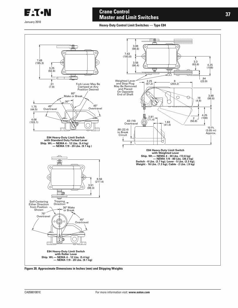
January 2010
CA05801001E For more information visit: www.eaton.com
37Crane ControlMaster and Limit SwitchesHeavy-Duty Control Limit Switches — Type E84
Figure 20. Approximate Dimensions in Inches (mm) and Shipping Weights
7.69(195.3)
3.25(82.6)
.31(7.9)
4.06(103.1)
1.75(44.5)
E84 Heavy-Duty Limit Switchwith Standard Duty Forked Lever
Ship. Wt.— NEMA 4 - 12 Lbs. (5.4 kg)— NEMA 7/9 - 20 Lbs. (9.1 kg )
45ºOvertravel
45ºOvertravel
60ºMake or Break
30º
Ship. Wt.
8.56(217.4)
3.91(99.3)
E84 Heavy-Duty Limit Switchwith Roller Lever
— NEMA 4 - 12 Lbs. (5.4 kg)— NEMA 7/9 - 20 Lbs. (9.1 kg)
Ship. Wt.
E84 Heavy-Duty Limit Switchwith Weighted Lever
Switch - 6 Lbs. (2.7 kg); Lever - 5 Lbs. (2.3 kg);Weight - 16 Lbs. (7.3 kg); Cable - 2 Lbs. (.9 kg)
— NEMA 4 - 30 Lbs. (13.6 kg)— NEMA 7/9 - 80 Lbs. (36.3 kg)
30º Makeor Break
45ºOvertravel
75ºOvertravel
Self-CenteringEither Directionfrom Position
Shown
7.63(193.8)
3.56(90.4)
.88 (22.4)to BreakCircuit
.63 (16)Overtravel
4.25(108)
3.3(83.8)
.94(23.9)
.19(4.8)
8(203.2)
2.81(71.4)
1.63(41.4)
2.25(57.2)
3.88(98.6)
3.88(98.6)
2(50.8)
4.25(108)
10 Ft.(3.05 m)Approx.
Weighted Leverand Stop Plug
May Be Removedand Placed
On OppositeEnd of Shaft
Fork Lever May BeClamped at AnyPosition Desired
TrippingDirection

January 2010
38
For more information visit: www.eaton.com CA05801001E
Crane ControlMaster and Limit SwitchesHeavy-Duty Control Limit Switches — Type E84
Catalog Number SelectionTable 62. Type E84 Limit Switch Catalog Numbering System
Product SelectionLever SwitchesWhen Ordering Specify■ Catalog Number of basic switch
from Table 63.■ Catalog Number for lever from
Table 64, or for switch with lever
assembled, change the last digit of the basic switch Catalog Number from N to the Suffix Code listed in Table 64.
■ Add Suffix Number of optional feature. See Options, Page 35.
Table 63. Basic Switch Selection — Lever Switches
� Contacts change state when lever is moved in one direction only. (See dimension drawings, Pages 36 – 37.)� Circuits are non-overlapping. Field convertible to 2NC-1NO, 3NO or 3NC.� Field convertible from spring return type.� Suffix 2 option not available with maintained position switches.
Table 64. Operating Lever
E 8 4 A A A 2
Parent Number
E84
Operation Type
A = Spring Return without Lever, NEMA 4B = Maintained without Lever, NEMA 4D = Spring Return without Lever, NEMA 7/9E = Maintained without Lever, NEMA 7/9
Mechanical Option
Blank = No Option2 = Operation in Both Directions —
Spring Return Switches Only
Circuit Arrangement
A = 2NO-1NCB = 1NO-2NC
Lever Type
A = Steel RollerC = Standard Duty ForkedD = Heavy-Duty ForkedN = None
Operator Type CircuitArrangement
Enclosure Type
NEMA 4 Cast Aluminum NEMA 7/9 Cast Iron
CatalogNumber
* CatalogNumber
*
Spring Return without Lever � 2NO-1NC � E84AAN E84DAN
Maintained Position without Lever �� 2NO-1NC � E84BAN E84EAN
Lever Type Code Suffix Change Last Digit of ListedCatalog Number
Lever OnlyCatalogNumber
*
Steel Roller A E84XA
Standard Duty Forked
C E84XC
Heavy-Duty Forked D E84XD
Cross-Reference to Previous Products. . . . . . . . . . . . . . . Page 39
Dimensions . . . . . . . . . . . . . . . . . . . . . . Pages 36, 37Discount Symbol . . . . . . . . . . . . . . . . . 18CD-4
* Consult Sales Office for Pricing

January 2010
CA05801001E For more information visit: www.eaton.com
39Crane ControlMaster and Limit SwitchesHeavy-Duty Control Limit Switches — Type E84
Hoist Service with Weighted Lever
Hoist Switches
When Ordering Specify■ Catalog Number for basic switch from Table 65.
Table 65. Basic Switch Selection — Hoist Limit
� Circuits are non-overlapping. Field convertible to 2NO-1NC, 3NO or 3NC.
Cross-Reference to Previous ProductTable 66. Control Limit Switch Cross-Reference
OperatorType
CircuitArrangement
Enclosure Type
NEMA 4Cast Aluminum
NEMA 7/9Cast Iron
CatalogNumber
* CatalogNumber
*
Maintained Position withWeighted Lever Only
2NC-1NO � E84CBF E84FBF
Maintained Position with Weighted Lever, Cable and Reset Weight
2NC-1NO � E84CBE E84FBE
Catalog Number Catalog Number Catalog Number
Old New Old New Old New
Limit Switch OperatingLever
Limit Switch OperatingLever
Limit Switch OperatingLever
14977H1014977H1114977H1214977H1314977H14
E84AANE84AANE84AANE84ABAE84ABA
E84XAE84XAE84XA——
14977H2714977H2914977H3014977H3114977H32
E84CBEE84BANE84BANE84BANE84EAN
—E84XDE84XDE84XDE84XD
14977H4214977H4314977ED12-214977ED15-514977ED18-1
——E84EAD w/OverlapE84FAEE84DAN
E84XCE84XB——E84XA
14977H1514977H1614977H1714977H1814977H19
E84ABAE84AANE84AANE84AANE84BAN
—E84XAE84XAE84XAE84XC
14977H3314977H3414977H3514977H3614977H37
E84AANE84AANE84AANE84BANE84BAN
—————
14977ED23-114977ED23-214977ED26-114977ED26-214977ED26-3
E84DANE84DBAE84DAA2E84DBA2E84DAA2
E84XA————
14977H2014977H2114977H2514977H26
E84BANE84BANE84CBEE84CBE
E84XCE84XC——
14977H3814977H3914977H4014977H41
E84BANE84EAN——
——E84XAE84XD
14977ED27-214977ED28-1——
E84DBA w/OverlapE84EBD w/Overlap——
————
Dimensions. . . . . . . . . . . . . . . . . . . . . . . Pages 36, 37Discount Symbol . . . . . . . . . . . . . . . . . . 18CD-4
* Consult Sales Office for Pricing

January 2010
40
For more information visit: www.eaton.com CA05801001E
Crane ControlMaster and Limit SwitchesHigh Speed Limit Switches
High Speed Limit Switches
High Speed Limit Switchwith Cover Removed
Product DescriptionThese rugged, heavy-duty limit switches are designed for use in high-speed applications such as cranetrolleys, conveyors and similar types of moving machinery. Our High Speed Limit Switches are supplied with three non-overlapping contacts and main-tained lever operation. Only the forked lever version is available.
Standards and Certifications■ CMAA 70-5.9.5.■ NEMA ICS2-215.07.■ NEMA ICS2-125.21.02.
Technical Data and Specifications■ Voltage: 600 V maximum, ac or dc.■ Current Rating:
❑ 1.25 A at 250 Vdc continuous■ Ambient Temperature: 100°C
maximum, operating.
■ Operation: Mechanical trip.■ Operating Speeds:
❑ 1200 feet per minute
Table 67. 14977 Control Circuit Ratings
Dimensions
Figure 21. Approximate Dimensions in Inches (mm) and Shipping Weights
Product SelectionWhen Ordering Specify■ Catalog Number.
Table 68. Type 14977 Direct Acting Limit Switches
Maximum Current Amperes
ac dc Inductive
120 V 240 V 480 V 125 V 250 V
Make Break Make Break Make Break Make Break
60 6.0 30 3.0 15 1.5 2.2 1.1
Type ofOperating Lever
With or withoutSpring Return
Numberof Circuits
NEMA TypeEnclosure
CatalogNumber
*
1NO-2NC Circuits (Without Overlap)Forked Lever 1200 ft./min. Maximum
Without 3 4 14977H28
7.88 R(200.2)
.56 (14.2) Dia.4 Holes
1.25 (31.8) Conduit Hole
14977 High Speed Limit SwitchShip. Wt. — 100 Lbs. (45.4 kg)
.19(4.8)
9(228.6)
2.75(69.9)
8.56(217.4)
12.13 (308.1)
11 (279.4)
13.38 (339.9)
6 (152.4)
63ºNormal63º
Normal
35º35º
Min. Travel toReset Fork Lever
Min. Travel toTrip Fork Lever
ExtremePositions
of OperatingBar
Discount Symbol . . . . . . . . . . . . . . . . . . . . . . . 18CD-4* Consult Sales Office for Pricing

January 2010
CA05801001E For more information visit: www.eaton.com
41Crane ControlMaster and Limit SwitchesFoot-Operated Limit Switches
Lever May Be Installed on Either Side
Product DescriptionThese heavy-duty Foot-Operated Limit Switches are designed for use in mill applications, on moving machinery, or in other heavy-duty applications. They can be used as STOP devices or master switch controls. They are supplied with three contacts without overlap.
Standards and Certifications■ NEMA ICS2-215.07.■ NEMA ICS2-125.21.02.
Technical Data andSpecifications■ Voltage: 600 V maximum, ac or dc.■ Current Rating:
❑ 1.25 A at 250 Vdc continuous, breaking ratings per Table 69.
■ Ambient Temperature: ❑ 100°C maximum, operating
■ Operation: Mechanical, foot-operated.
Table 69. 14953 Control Circuit Ratings
Renewal PartsTable 70. 14953 Renewal Parts
Note: For prices, refer to Eaton’s parts distributor or consult factory.
Dimensions
Figure 22. Approximate Dimensions in Inches (mm) and Shipping Weights
Product SelectionWhen Ordering Specify■ Catalog Number.
Table 71. Type 14953 Foot-Operated Switches
Maximum Current Amperes
ac dc Inductive
120 V 240 V 480 V 125 V 250 V
Make Break Make Break Make Break Make Break
60 6.0 30 3.0 15 1.5 2.2 1.1
Description Part Number
Contact Block Assembly 83-530-5
ContactArrangement
NEMA TypeEnclosure
CatalogNumber
*
2NO-1NC 74
14953H4014953H41
14953 Foot-Operated Master SwitchShip. Wt. — 20 Lbs. (9.1 kg)
3.25(82.6)3.94 R
(100.1)
2.44(62)
4.13(104.9)
3.75(95.3)
3.81(96.8)
8.63 (219.2)
7.38 (187.5)
30º
Lever May BeClamped at AnyPosition Desired
Overtravel is75º Each Side ofCenter Position
.75 (19.1) Pipe Tap 2 Holes
Discount Symbol . . . . . . . . . . . . . . . . . . . . . . . 18CD-4* Consult Sales Office for Pricing

January 2010
42
For more information visit: www.eaton.com CA05801001E
Crane ControlMaster and Limit SwitchesCable-Operated Limit Switches
Cable-Operated Limit Switch
Product DescriptionThe Cable-Operated Limit Switch is a latched-in type safety switch for use on rubber mills, calendars, tubers and Banburys. A slight movement of the trip lever moves the star wheel to the trip position to cause a quick, positive operation of the contact mechanism.
A manual reset lever is provided, attached directly to the operating shaft at the other side of the switch.
Both the trip and reset levers are arranged for rope operation and are mounted on a serrated shaft that per-mits mounting in any desired position.
Standards and Certifications■ NEMA ICS2-215.07.■ NEMA ICS2-125.21.02.
Technical Data andSpecifications■ Voltage: 600 V maximum, ac or dc.■ Current Rating:
❑ 1.25 A at 250 Vdc continuous, breaking ratings per Table 72.
■ Ambient Temperature: ❑ 100°C maximum, operating
■ Operation: Mechanical trip.
Table 72. 14957 Control Circuit Ratings
Renewal PartsTable 73. 14957 Renewal Parts Note: For prices, refer to Eaton’s parts
distributor or consult factory.
Dimensions
Figure 23. Approximate Dimensions in Inches (mm) and Shipping Weights
Product SelectionWhen Ordering Specify■ Catalog Number.
Table 74. Type 14957 Cable-Operated Safety Switches
Maximum Current Amperes
ac dc Inductive
120 V 240 V 480 V 125 V 250 V
Make Break Make Break Make Break Make Break
60 6.0 30 3.0 15 1.5 2.2 1.1
Description Part Number
Contact Block Assembly 83-530-5
Numberof Poles
Contact Arrangement
NEMA TypeEnclosure
CatalogNumber
*
33
2NC, 1NO without Overlap2NC, 1NO without Overlap
127
14957H914957H8
4(101.6)
4.13 (104.9) w/o Gasket4.19 (106.4) w/ Gasket
1.5(38.1)
14957 Heavy-Duty Limit SwitchCable Operated
Ship. Wt. — 20 Lbs. (9.1 kg)
3.13(79.5)
2.31(58.7)
1.13(28.7)
.5(12.7)
35ºOvertravel
40ºto BreakCircuit
Levers May Be Clampedat Any Position Desired
.38 (9.7) Dia.Hole for Cable
TrippingDirection
Res
etD
irec
tio
n
When Lever Is Tripped toBreak Circuit, Switch Must
Be Reset to RemakeCircuit
7.5(190.5)
8.38 (212.9)
7.38 (187.5)
3.75(95.3)
2.41 (61.2)Dia. Holes
.19(4.8)
.88(22.4)
3.84(97.5)
7.69(195.3)
.19(4.8)
.75 (19.1) Pipe Tap2 Holes
Discount Symbol . . . . . . . . . . . . . . . . . . . . . . . 18CD-4* Consult Sales Office for Pricing

CA05801001E For more information visit: www.eaton.com
43Crane Control
January 2010Contactors and RelaysDC Contactors — Type C80
Cat. No. C80FJ421N00Size 4 — NC Contactor
Product DescriptionThese dc mill type contactors are designed for heavy industry service and are suitable for use on moving machinery. The contactors listed in this section are for surface mounting on steel panels and front-of-panel wiring. The power stud assembly is mounted on the side of the contactor, rather than as part of a separate mounting kit.
These contactors utilize dc coils. If control power is 120 Vac, the rectifier module listed on Page 44 should be used in conjunction with a 100 V coil contactor.
Auxiliary contacts and mechanical interlocks for use with these contac-tors are listed on the following pages.
The contactors feature forged steel armature levers and magnet frames for superior physical strength. Self-lubricating bearings eliminate the need for lubricating the contactor. Hot-molded arc chute assemblies contain no asbestos and have better arc extinc-tion characteristics for longer contact life. The short stroke armature results in a mechanical life of more than 20 million operations.
The arc chutes and magnetic blowout structures are designed to quickly absorb and dissipate the heat caused by arcing. In addition to increasing contact life, the molded arc chute
Cat. No. C80DG221N00Size 2 — 2 Pole Contactor
offers advantages of improved mechanical life and cooling character-istics plus superior arc-tracking resis-tance. The arc chutes are hinged to provide front accessibility, easy inspection or replacement of contacts without removing any other contactor parts.
Construction of the pivot pin assembly provides positive pin locking so that the bearing pin remains stationary with respect to the operating move-ment of the forged armature.
A leaf spring attached to the unit base and the arc chute holds the chute in the “down” or functioning position. The addition of this assembly resists the violent vibrations encountered on open hearth charging machines and on a wide variety of crane applications.
Pre-drilled mounting holes are provided on the unit base to accommodate interlock mounting brackets. An inter-lock is merely attached to a bracket and the assembly is then bolted in the desired operating position on the contactor.
DC Drive Service ContactorsEaton’s Cutler-Hammer industrial type contactors modified for dc drive service are provided with silver faced contact tips, to provide optimum con-tact structure and minimum mainte-nance under continuous duty service. These contactors are designed for steel panel surface mounting.
Power studs are a part of the contactor assembly.
Standards and Certifications■ CMAA 5.6.6-2.■ NEMA ICS3-441, 442, 443.■ NEMA ICS2-331.23.■ NEMA ICS2-110.05.02.■ NEMA ICS2-125.21.02.
Technical Data andSpecifications■ Current Range: 5 to 1800 amperes.■ Voltage: 600 Vdc.■ Operation: Magnetic.■ Mounting: Steel Panel.■ Mechanical Life: 20 million
operations.■ Electrical Life: 500,000 operations.■ Interlock Ratings:
❑ 10 amperes continuous❑ 2.2 amperes inductive breaking
at 115 V❑ 1.1 amperes inductive breaking
at 230 V■ Duty:
❑ Continuous (for intermittent ratings consult factory)
Table 75. Coil Ampere Data
� Inrush/sealed current.� Coil used with series resistor.
NEMASize
No. of Poles
100 VdcCoil
115 VdcCoil
230 VdcCoil
2 1NO2NO
.288 .339
.263 .274
.125
.140
3 1NO1NC
.268 .339
.235 .274
.112
.140
4 1NO1NC
.268 .339
.235 .274
.112
.140
5 1NO1NC
.433 .424
.391 .329
.187
.164
6 1NO1NC
.4501.832/ .597 �
.3651.337/ .485 �
.200
.714/
.267 �
6A 1NO .450 .365 .200
8 1NO .787 � .757 � .438 �

January 2010
44
For more information visit: www.eaton.com CA05801001E
Crane ControlContactors and RelaysDC Contactors — Type C80
Options
Other Options Available■ Silver Faced Contact Tips:
❑ Can be supplied in place of standard contact tipsNote: Use silver tips for non-arcing or long (8 hour) extended continuous current applications.
■ Special Voltage Coils: ❑ Coils with dc voltage ratings other
than those listed are available■ 1800 Ampere Contactors:
❑ Size 8 A (not a NEMA size) contactors are also available
■ Consult factory for pricing.
Accessories
Auxiliary ContactsTable 76. Mounting Kits for Auxiliary Contacts
� 10923H19 supplied with contactor as standard. No charge.
Table 77. Auxiliary Contacts — without Mounting Kit All Sizes Bottom Mounted
Table 78. Auxiliary Contacts — without Mounting Kit Size 2 Side Mount Only
RectifiersTable 79. Rectifier Module
Separate for Field Installation Factory Installed
For Size and Typeof Contactor
Location of AuxiliaryContacts on Contactorand Number of Units KitWill Mount
MaximumNumberof UnitsAcceptableperContactor
MountingKitCatalogNumber
* SuffixCodeLetterforFactoryInstalla-tion
Adder*
NEMASize
ContactorPower PoleConfiguration
Location No.ofUnits
2 1NO Bottom — Right and Left
2 2 10923H11 B
1NO or 1NO Ltl
Side — Right or Left
1 1 10923H12 A
2NO Bottom — Right and LeftSide — Left Side — Right
1
11
2
22
10923H14
10923H1510923H16
B
AA
2NO-1NC Side — LeftSide — Right
11
22
10923H1510923H16
AA
3, 4and 5
1NO Bottom — Right and LeftBottom — Left Only
2
1
2
1
10923H19
10923H38
B
B
1NO Ltl or1NC
Bottom — Right 1 1 10923H20 B
6, 6A, 8and 8A
1NO Bottom — Right and LeftBottom — Left Only
2
1
2
1
10923H19
10923H38
B
B
1NO Ltl Bottom — Right 1 1 10923H20 B
1NC Bottom — Right 1 1 � —
Separate for Field Installation Factory Installed
Suffix CodeLH Position
Adder *
Suffix CodeRH Position
Adder *
ContactConfiguration
CatalogNumber
*
None1NO2NO1NO-1NC1NC2NC
—10923H110923H210923H310923H410923H5
012345
012345
Separate for Field Installation Factory Installed
Suffix CodeLH Position
Adder *
Suffix CodeRH Position
Adder *
ContactConfiguration
CatalogNumber
*
None1NO2NO1NO-1NC1NC
—10923H610923H710923H810923H9
01234
01234
Description Contactor Size Catalog Number *
120 Vac Input100 Vdc Output 3.5 Amps
All C81EB
Discount Symbol . . . . . . . . . . . . . . . . . . . . . . 18CD-4* Consult Sales Office for Pricing

January 2010
CA05801001E For more information visit: www.eaton.com
45Crane ControlContactors and RelaysDC Contactors — Type C80
Mounting Kits and Mechanical InterlocksTable 80. Contactor Mounting Kits � and Mechanical Interlocks
� Mounting kits include power studs and stud mounting, as well as contactor mounting hardware, but do not include lugs.
Renewal PartsTable 81. Renewal Parts �
� For prices refer to Eaton’s parts distributor or call factory.� Magnet closing coil only. If holdout coil is required, give number stamped on coil or advise Bulletin or Serial Number of controller.� Series resistor used with coil for voltage shown.
NEMASize
No. ofPoles
Type of Mounting For Metal Panels
CatalogNumber
*
Mounting Kits3, 4 1 Surface, Front-of-Panel Wiring
Elevated, Front-of-Panel WiringC81AEA11C81AEA13
5 1 Surface, Front-of-Panel WiringElevated, Front-of-Panel Wiring
C81AGA11C81AGA13
6, 6A 1 Surface, Front-of-Panel WiringElevated, Front-of-Panel Wiring
C81AJA11C81AJA13
8, 8A 1 Surface, Front-of-Panel WiringElevated, Front-of-Panel Wiring
C81ALA11C81ALA13
Mechanical Interlocks2 1
23
Surface C81DDA11C81DDA12C81DDA13
3, 4 1 SurfaceElevated
C81DEA11C81DEA21
5 1 SurfaceElevated
C81DGA11C81DGA21
6, 6A 1 SurfaceElevated
C81DJA11C81DJA21
8, 8A 1 SurfaceElevated
C81DLA11C81DLA21
Description Size 2, 1-Pole, 2-Pole3-Pole and Ltl25 & 50 Ampere
Size 3, 1-PoleNO, NC and Ltl100 Ampere
Size 4, 1-PoleNO, NC and Ltl150 Ampere
Size 5, 1-PoleNO, NC and Ltl300 Ampere
Size 6, 1-PoleNO, NC and Ltl600 Ampere
Size 6A, 1-PoleNO, NC and Ltl810 Ampere
Size 8, 1-Pole NO1350 Ampere
Part Number Part Number Part Number Part Number Part Number Part Number Part Number
Set of Contacts1-Pole Copper1-Pole Silver2-Pole Copper3-Pole Copper
6-599—6-169-46-169-5
6-1896-189-5——
6-1896-189-5——
6-189-36-189-7——
6-189-46-189-8——
6-189-46-189-8——
6-2156-215-2——
Arc ShieldRight-HandLeft-Hand
73-2676-273-2676
62-79162-791-2
62-79162-791-2
62-79362-793-2
62-84062-840-2
62-84062-840-2
62-80462-804
Coils1-Pole NO 100 V
115 V230 V
9-1549-189-1549-29-1549-1
9-1583-159-1583-29-1583-1
9-1583-159-1583-29-1583-1
9-1589-109-1589-29-1589-1
9-1688-89-1688-29-1688-1
9-1688-89-1688-29-1688-1
9-547-7 �
9-547-7 �
9-547-4 �
1-Pole NC 110 V115 V230 V
———
9-1585-189-1585-29-1585-1
9-1585-189-1585-29-1585-1
9-967-139-967-89-967-7
9-1717-49-1717-19-1717-2
———
———
1-Pole Ltl � 100 V115 V230 V
9-1549-189-1549-29-1549-1
9-1583-159-1583-29-1583-1
9-1583-159-1583-29-1583-1
9-1589-109-1589-29-1589-1
9-1688-89-1688-29-1688-1
———
———
2-Pole 100 V115 V230 V
9-1585-189-1585-29-1585-1
———
———
———
———
———
———
3-Pole 110 V115 V230 V
9-1585-189-1585-29-1585-1
———
———
———
———
———
———
Discount Symbol . . . . . . . . . . . . . . . . . . . . . . . 18CD-4* Consult Sales Office for Pricing

January 2010
46
For more information visit: www.eaton.com CA05801001E
Crane ControlContactors and RelaysDC Contactors — Type C80
Dimensions
Figure 24. Approximate Dimensions and Shipping Weights
Table 82. Type C80
� May be reduced to 2.5 (63.5) for Size 3.� May be reduced to 3.5 (88.9) for Size 3.
Size Poles Approximate Dimensions in Inches (mm) Ship. Wt.Lbs. (kg)
StudSizeWide High Deep Mounting With Auxiliary Contacts H Min. Arc Clearance
A B B1 C C1 D E F G G1 250 V 600 V
Open Type DC Contactors2 1NO 3
(76.2)8.38 (212.9)
6.5 (165.1)
6 (152.4)
5.38 (136.7)
2.25 (57.2)
4.5 (114.3)
7.38 (187.5)
10.88 (276.4)
9.13 (231.9)
— .59 (15.1)
.91 (23.0)
6 (2.7) 1/4-20
2NO 5.75 (146.1)
8.88 (225.6)
8.88 (225.6)
6.88 (174.8)
6.5 (165.1)
5 (127.0)
4.63 (117.6)
10.13 (257.3)
11.38 (289.1)
11.38 (289.1)
— 1.19 (30.2)
2.19 (55.6)
10 (4.5)
2NO-1NC 5.75 (146.1)
12.63 (320.8)
12.63 (320.8)
6.88 (174.8)
6.5 (165.1)
5 (127.0)
8.38 (212.9)
10.13 (257.3)
— — — 1.19 (30.2)
2.19 (55.6)
13 (5.9)
3, 4 1NO 4.25 (108.0)
12.13 (308.1)
12.13 (308.1)
7.25 (184.2)
6.38 (162.1)
— 11.25 (285.8)
4.5 (114.3)
12.13 (308.1)
12.13 (308.1)
1.63 (41.4)
2.75 �(69.9)
3.75 �(95.3)
11 (5) 3/8-16
1NC 4.25 (108.0)
13.63 (346.2)
13.63 (346.2)
7.25 (184.2)
5.63 (143.0)
— 12.75 (323.9)
5 (127.0)
13.63 (346.2)
13.63 (346.2)
1.63 (41.4)
4.25 �(108.0)
5.25 �(133.4)
13 (5.9)
5 1NO 5.13 (130.3)
16.88 (428.8)
16.88 (428.8)
10 (254.0)
8 (203.2)
1.25 (31.8)
16 (406.4)
5.13(130.3)
16.88 (428.8)
16.88(428.8)
1.88 (47.8)
3.5 (88.9)
4.5 (114.3)
26 (12) 1/2-13
1NC 5.25 (133.4)
18.88 (479.6)
16.88 (428.8)
10 (254.0)
7.5 (190.5)
1.25 (31.8)
18 (457.2)
6.13 (155.7)
18.88 (479.6)
18.88 (479.6)
1.88 (47.8)
3 (76.2)
4 (101.6)
34 (15)
6 1NO 7.13 (181.1)
18.75 (476.3)
16.88 (428.8)
12.25 (311.2)
9.5 (241.3)
1.25 (31.8)
17.5 (444.5)
7.13 (181.1)
18.75 (476.3)
18.75 (476.3)
1.88 (47.8)
5.5 (139.7)
5.5 (139.7)
43 (20) 3/4-12
1NC 7.25 (184.2)
22.88 (581.2)
18.88 (479.6)
12.25 (311.2)
9.88 (251.0)
1.25 (31.8)
22 (558.8)
7.25 (184.2)
22.88 (581.2)
22.88 (581.2)
1.88 (47.8)
5.5 (139.7)
5.5 (139.7)
66 (30)
6A 1NO 7.63 (193.8)
18.75 (476.3)
18.75 (476.3)
12.25 (311.2)
9.5 (241.3)
1.25 (31.8)
17.5 (444.5)
7.63 (193.8)
18.75 (476.3)
18.75 (476.3)
1.88 (47.8)
5.5 (139.7)
5.5 (139.7)
45 (20) 3/4-12
8, 8A 1NO 9.5 (241.3)
24 (609.6)
22.5 (571.5)
17 (431.8)
14.88 (378.0)
7 (177.8)
10 (254.0)
9.5 (241.3)
24 (609.6)
24 (609.6)
2 (50.8)
8 (203.2)
10 (254.0)
130 (59) 1/2 hole
Definite Purpose Contactors260A 1NO 4.25
(108.0)12.13 (308.1)
12.13 (308.1)
7.25 (184.2)
6.38 (162.1)
— 11.25 (285.8)
4.5 (114.3)
12.13 (308.1)
12.13 (308.1)
1.63 (41.4)
2.5 (63.5)
3.5 (88.9)
11 (5) 3/8-16
1NC 4.25 (108.0)
13.63 (346.2)
13.63 (346.2)
7.25 (184.2)
5.63 (143.0)
— 12.75 (323.9)
5 (127.0)
13.63 (346.2)
13.63 (346.2)
1.63 (41.4)
2.5 (63.5)
3.5 (88.9)
13 (5.9)
480A 1NO 5.13 (130.3)
16.88 (428.8)
16.88 (428.8)
10 (254.0)
8 (203.2)
1.25 (31.8)
16 (406.4)
5.13 (130.3)
16.88 (428.8)
16.88 (428.8)
1.88 (47.8)
3 (76.2)
4 (101.6)
26 (12) 1/2-13
1NC 5.25 (133.4)
18.88 (479.6)
16.88 (428.8)
10 (254.0)
7.5 (190.5)
1.25 (31.8)
18 (457.2)
6.13 (155.7)
18.88 (479.6)
18.88 (479.6)
1.88 (47.8)
3 (76.2)
4 (101.6)
34 (15)
960A 1NO 7.63 (193.8)
18.75 (476.3)
18.75 (476.3)
12.25 (311.2)
9.5 (241.3)
1.25 (31.8)
17.5 (444.5)
7.63 (193.8)
18.75 (476.3)
18.75 (476.3)
1.88 (47.8)
5.5 (139.7)
5.5 (139.7)
45 (20) 3/4-12
E
Open Type
BWith
Blowout B1WithoutBlowout
GWith
BlowoutG1
WithoutBlowout
FA
C With Blowout HC1
WithoutBlowout
D
Ele
vate
dM
ou
nti
ng

January 2010
CA05801001E For more information visit: www.eaton.com
47Crane ControlContactors and RelaysDC Contactors — Type C80
Catalog Number SelectionTable 83. DC Contactor Catalog Numbering System
� Not an actual NEMA size.
C 8 0 E H 4 2 1 B 0 2
NEMA Size
D = Size 2E = Size 3F = Size 4G = Size 5
J = Size 6K = 6A �W = Size 8
Blowout Coil Rating
X = NoneC = 5D = 10F = 25G = 50H = 100
J = 150K = 300L = 600M = 810N = 1350
BaseCatalog Number
C80
Power PoleConfiguration
1 = 1NO2 = 2NO4 = 1NC Coil
Voltage
1 = 115 Vdc2 = 230 Vdc4 = 100 Vdc
Type of Mounting
0 = None1 = Surface, Front of Panel3 = Elevated, Front of Panel
Auxiliary Contact Location
A = Size 2 Side MountedB = Size 2 thru 8 Bottom Mounted
w/LH and/or RH InterlockN = None
RH Auxiliary Contacts
1 = 1NO2 = 2NO3 = 1NO-1NC
4 = 1NC0 = None
LH Auxiliary Contacts
1 = 1NO2 = 2NO3 = 1NO-1NC
4 = 1NC0 = None

January 2010
48
For more information visit: www.eaton.com CA05801001E
Crane ControlContactors and RelaysDC Contactors — Type C80
Product SelectionWhen Ordering■ Select complete Catalog Number
from Tables 84, 85 or 86 below. If contactor is to include factory assembled auxiliary contacts, change N00 Suffix to correct Suffix letter and digits from Tables 76 and 77 on Page 44.
Example: Catalog Number for ele-vated Size 3 NO contactor, 230 Vdc coil with 2NO auxiliary contact bottom mounted on RH side of contactor is C80EH123B02.
DC ContactorsTable 84. Surface Mounted DC Contactors w/o Auxiliary Contacts
� Not a NEMA size.
Table 85. Elevated Mounted DC Contactors w/o Auxiliary Contacts
� Not a NEMA size.
DC Drive Service ContactorsTable 86. Surface Mounted DP Drive Service Contactors w/o Auxiliary Contacts
� Discount Symbol 18CD-4.
NEMASize
Numberof Poles
Blowout CoilAmpere
Catalog Number *
100 Vdc Coil 115 Vdc Coil 230 Vdc Coil
2 1NO None 5 10 25 50
C80DX141N00C80DC141N00C80DD141N00C80DF141N00C80DG141N00
C80DX111N00C80DC111N00C80DD111N00C80DF111N00C80DG111N00
C80DX121N00C80DC121N00C80DD121N00C80DF121N00C80DG121N00
2NO None 5 10 25 50
C80DX241N00C80DC241N00C80DD241N00C80DF241N00C80DG241N00
C80DX211N00C80DC211N00C80DD211N00C80DF211N00C80DG211N00
C80DX221N00C80DC221N00C80DD221N00C80DF221N00C80DG221N00
3 1NO1NC
100 100
C80EH141N00C80EH441N00
C80EH111N00C80EH411N00
C80EH121N00C80EH421N00
4 1NO1NC
150 150
C80FJ141N00C80FJ441N00
C80FJ111N00C80FJ411N00
C80FJ121N00C80FJ421N00
5 1NO1NC
300 300
C80GK141N00C80GK441N00
G80GK111N00C80GK411N00
C80GK121N00C80GK421N00
6 1NO1NC
600 600
C80JL141N00C80JL441N00
C80JL111N00C80JL411N00
C80JL121N00C80JL421N00
6A � 1NO 810 C80KM141N00 C80KM111N00 C80KM121N00
8 1NO 1350 C80WN141N00 C80WN111N00 C80WN121N00
NEMASize
Numberof Poles
Blowout CoilAmpere
Catalog Number *
100 Vdc Coil 115 Vdc Coil 230 Vdc Coil
3 1NO1NC
100 100
C80EH143N00C80EH443N00
C80EH113N00C80EH413N00
C80EH123N00C80EH423N00
4 1NO1NC
150 150
C80FJ143N00C80FJ443N00
C80FJ113N00C80FJ413N00
C80FJ123N00C80FJ423N00
5 1NO1NC
300 300
C80GK143N00C80GK443N00
G80GK113N00C80GK413N00
C80GK123N00C80GK423N00
6 1NO1NC
600 600
C80JL143N00C80JL443N00
C80JL113N00C80JL413N00
C80JL123N00C80JL423N00
6A � 1NO 810 C80KM143N00 C80KM113N00 C80KM123N00
8 1NO 1350 C80WN143N00 C80WN113N00 C80WN123N00
Number of Poles
AmpereRating
CatalogNumber100 Vdc Coil
* �
1NO1NC
260260
C80RK141N00C80RK441N00
1NO1NC
480480
C80SL141N00C80SL441N00
1NO 960 C80TM141N00
Options. . . . . . . . . . . . . . . . . . . . . . . . . Page 44Accessories . . . . . . . . . . . . . . . . . . . . Page 44Dimensions . . . . . . . . . . . . . . . . . . . . . Page 46Cross-Reference to
Previous Numbers. . . . . . . . . . . . . . Pages 49 – 52Discount Symbol . . . . . . . . . . . . . . . . 18CD-1
* Consult Sales Office for Pricing

January 2010
CA05801001E For more information visit: www.eaton.com
49Crane ControlContactors and RelaysDC Contactors — Type C80
Cross-Reference to Previous NumbersTable 87. Old Catalog Numbering System
Table 88. Electrical Interlock and/or Pneumatic Timing Interlock Assemblies
� Pneumatic interlocks are no longer available. Use C84 in-line timers as replacements. Consult factory for details.
Description Location MountingPlate
Circuit Index Number
NumberRequired
Mounting Plateand Driver
Handling Suffix Number
Index Number
NumberRequired
Size 3 Size 4, 56 & 6A
Size 8 & 8A
NO(NormallyOpen)Contactors
Without Interlock None — — — — — 1 1 1
Unit Electrical Interlocks Only
BottomMounted
LH & RHLH
FullFull
4NO2NO
10923H2A10923H2A
21
10923H19A10923H38A
11
319
317
317
Unit Electrical Interlocks and Pneumatic Timing Interlocks �
BottomMounted
LHRH
Full 2NO1TC & 1TO
10923H2A10923H25B(ON Delay)
11
10923H19A 1 13 11 —
LHRH
Full 2NO1IO & 1IC
10923H2A10923H26B(OFF Delay)
11
10923H19A 1 14 12 —
Pneumatic Timing Interlocks Only �
BottomMounted
RHRH
FullFull
1TC & 1TO1IO & 1IC
10923H25B10923H26B(ON Delay)
11
10923H38A10923H38A
11
2021
1819
—19
6 0 0 2 H 4 5 2 B 1 0 3 C 3
Revision Code
A, B or C
Coil Voltage
100 = 100 Vdc101 = 115 Vdc103 = 230 Vdc109 = 550 Vdc
Electrical Interlocks
See Tables 88, 89 and 90.
Mounting and Latch Options
SuffixCode
Type ofPanel
Application
A — No Mounting Material
H Metal Elevated — FrontConnected — Dead Back
C Metal Surface Mounted — FrontConnected — Dead Back
D Metal Surface Mounted — Rear Connected
E InsulatedMaterial
Elevated — Front Connected
F InsulatedMaterial
Surface Mounted — Front Connected
G InsulatedMaterial
Surface Mounted — Rear Connected
– — Size 2 Only — without Latch
X — Size 2 Only — with Latch
BaseCatalog Number
6002H452

January 2010
50
For more information visit: www.eaton.com CA05801001E
Crane ControlContactors and RelaysDC Contactors — Type C80
Table 89. Size 2 DC Contactors, Unit Electrical Interlock and/or Pneumatic Timing Interlock
� Pneumatic interlocks are no longer available. Use C84 in-line timers as replacements. Consult factory for details.
Table 90. Electrical and/or Pneumatic Timing Interlock Assemblies
� Pneumatic interlocks are no longer available. Use C84 in-line timers as replacements. Consult the factory for details.
Description Location MountingPlate
Circuit Index Number
NumberRequired
Mounting Plate and Driver HandlingSuffixNumber
Index Number
NumberRequired
Size 21NO(NormallyOpen)Contactor
Without Interlock — — — — — — — 1
Unit Electrical Interlocks Only
BottomMounted(Pre-wired)
LHLH & RH
FullFull
2NO4NO
10923H2A10923H2A
12
10923H11A10923H11A
11
23
LHRH
HalfHalf
2NO2NO
10923H2A10923H2A
11
10923H17A10923H17A
11
45
SideMount
LHRHLH & RH
———
2NO2NO4NO
10923H7A10923H7A10923H7A
112
10923H12A10923H12A10923H12A
112
678
Unit Electrical Interlocks and Pneumatic Timing Interlocks �
BottomMountedOnly
RHLH
FullFull
2NO1TC & 1TO
10923H2A10923H24B(ON Delay)
11
10923H11A10923H11A
11
1515
RHLH
FullFull
2NO1IO & 1IC
10923H2A10923H24B(OFF Delay)
11
10923H11A10923H11A
11
1616
Pneumatic Timing Interlocks Only �
LH Full 1TC & 1TO 10923H24B(ON Delay)
1 10923H11A 1 17
LH Full 1IO & 1IC 10923H26B(OFF Delay)
1 10923H11A 1 18
LH Full 1TC & 1TO 10923H24B(ON Delay)
1 10923H17A 1 19
LH Full 1IO & 1IC 10923H26B(OFF Delay)
1 10923H17A 1 20
Size 22NO(NormallyOpen)Contactor
Without Interlock — — — — — — — 1
Unit Electrical Interlocks
Bottom(Pre-wired)
LHLH & RH
FullFull
2NO4NO
10923H2A10923H2A
12
10923H14A10923H14A
11
23
SideMount
LHRH
——
2NO2NO
10923H7A10923H7A
11
10923H15A10923H16A
11
45
LH & RH — 4NO 10923H7A 2 10923H15A10923H16A
11
6
Size 22NO-1NCContactor
Without Interlock None — — — — — — 11
Unit Electrical Interlocks
SideMount
LHRH
——
2NO2NO
10923H7A10923H7A
11
10923H15A10923H15A
11
23
LH & RH — 4NO 10923H7A 2 10923H15A10923H16A
11
4
Description Location MountingPlate
Circuit Index Number
NumberRequired
Mounting Plate and Driver Handling Suffix Number
IndexNumber
NumberRequired
Size3 and 4
Size 5 Size6 and 6A
NC(NormallyClosed)dcContactor
Without Interlock None — — — — — 1 1 1
Unit Electrical Interlocks Only �
Bottom RH Single 2NO 10923H2A 1 10923H20A 1 2 2 2
Pneumatic Timing Interlocks Only �
Bottom RH Single 1TC & 1TO 10923H26B(ON Delay)
1 10923H30A 1 6 5 —
RH Single 1IC & 1IC 10923H31B(OFF Delay)
1 10923H30A 1 7 6 —

January 2010
CA05801001E For more information visit: www.eaton.com
51Crane ControlContactors and RelaysDC Contactors — Type C80
Table 91. Old/New Catalog Number Cross-Reference
� Catalog Numbers and prices listed for C80 devices include surface mounting kit and 240 Vdc coil. For C80 and C81 prices, see Pages 44, 45 and 48.
Table 91. Old/New Catalog Number Cross-Reference (Continued)
� Enclosed contactors no longer available. Select equivalent open contactor. Enclosure by others.
Old Number ReplacementNumber �
Description CatalogNumberCatalog
NumberSize Contact
Config-uration
BlowoutCoil Rating(Amperes)
Enclosure
6002H3316002H3326002H3336002H3346002H335
11111
1NO1NO1NO1NO1NO
None125
10
OpenOpenOpenOpenOpen
C80DX121N00C80DC121N00C80DC121N00C80DC121N00
C80DD121N00
6002H3366002H3376002H3386002H3396002H340
12222
1NO1NO1NO1NO1NO
25None
51015
OpenOpenOpenOpenOpen
C80DF121N00C80DX121N00C80DC121N00C80DD121N00C80DF121N00
6002H3416002H3426002H3436002H3446002H345
22111
1NO1NO2NO2NO2NO
2550125
OpenOpenOpenOpenOpen
C80DF121N00C80DG121N00C80DC221N00C80DC221N00C80DC221N00
6002H3466002H3476002H3486002H3496002H350
11222
2NO2NO2NO2NO2NO
10255
1015
OpenOpenOpenOpenOpen
C80DF221N00C80DF221N00C80DC221N00C80DF221N00C80DF221N00
6002H3516002H3526002H3536002H3546002H355
22222
2NO2NO2NO-1NC2NO-1NC2NO-1NC
25505 (NO & NC)
10 (NO & NC)15 (NO & NC)
OpenOpenOpenOpenOpen
C80DF221N00C80DG221N006002H353-1036002H354-1036002H355-103
6002H3566002H3576002H3836002H3846002H385
22111
2NO-1NC2NO-1NC1NO1NO1NO
25 (NO & NC)50 (NO & NC)
None12
OpenOpenNEMA 1NEMA 1NEMA 1
C80DGG32C80DGG32Cancelled �Cancelled �Cancelled �
6002H3866002H3876002H3886002H3896002H390
11122
1NO1NO1NO1NO1NO
51025
None5
NEMA 1NEMA 1NEMA 1NEMA 1NEMA 1
Cancelled �Cancelled �Cancelled �Cancelled �Cancelled �
6002H3916002H3926002H3936002H3946002H395
22221
1NO1NO1NO1NO2NO
101525501
NEMA 1NEMA 1NEMA 1NEMA 1NEMA 1
Cancelled �Cancelled �Cancelled �Cancelled �Cancelled �
6002H3966002H3976002H3986002H3996002H400
11112
2NO2NO2NO2NO2NO
25
10255
NEMA 1NEMA 1NEMA 1NEMA 1NEMA 1
Cancelled �Cancelled �Cancelled �Cancelled �Cancelled �
6002H4016002H4026002H4036002H4046002H405
22222
2NO2NO2NO2NO2NO-1NC
101525505 (NO & NC)
NEMA 1NEMA 1NEMA 1NEMA 1NEMA 1
Cancelled �Cancelled �Cancelled �Cancelled �Cancelled �
6002H4066002H4076002H4086002H4096002H410
22223
2NO-1NC2NO-1NC2NO-1NC2NO-1NC1NO
10 (NO & NC)15 (NO & NC)25 (NO & NC)50 (NO & NC)
None
NEMA 1NEMA 1NEMA 1NEMA 1Open
Cancelled �Cancelled �Cancelled �Cancelled �6002H410-103
6002H4116002H4126002H4136002H4146002H415
33333
1NO1NO1NO1NO1NO
5102550
100
OpenOpenOpenOpenOpen
6002H411-1036002H412-1036002H413-1036002H414-103C80EH121
6002H4166002H4176002H418
333
1NO1NO1NO
None5
10
NEMA 1NEMA 1NEMA 1
Cancelled �Cancelled �Cancelled �
Old Number ReplacementNumber �
Description CatalogNumberCatalog
NumberSize Contact
Config-uration
BlowoutCoil Rating(Amperes)
Enclosure
6002H4196002H4206002H4216002H4406002H441
33333
1NO1NO1NO1NC1NC
2550
100None
5
NEMA 1NEMA 1NEMA 1OpenOpen
Cancelled �Cancelled �Cancelled �6002H440-1036002H441-103
6002H4426002H4436002H4446002H4456002H446
33333
1NC1NC1NC1NC1NC
102550
100None
OpenOpenOpenOpenNEMA 1
6002H442-1036002H443-103C80EH421N00C80EH421N00Cancelled �
6002H4476002H4486002H4496002H4506002H451
33333
1NC1NC1NC1NC1NC
5102550
100
NEMA 1NEMA 1NEMA 1NEMA 1NEMA 1
Cancelled �Cancelled �Cancelled �Cancelled �Cancelled �
6002H4526002H4536002H4546002H4556002H456
44444
1NO1NO1NO1NO1NC
None150None150None
OpenOpenNEMA 1NEMA 1Open
C80FX121N00C80FJ121N00Cancelled �Cancelled �C80FX421
6002H4576002H4586002H4596002H4606002H461
41212
1NC2NO2NO2NO2NO
150NoneNoneNoneNone
OpenOpenOpenNEMA 1NEMA 1
C80FJ421N00C80DX22N00C80DX22N00Cancelled �Cancelled �
6002H4656002H4666002H467
356 & 810 A
Contactor Mounting Kits1 P, Surface, Front of Panel,for Metal Panel
C81AEA11C81AGA11C81AJA11
6002H4686002H4696002H470
3 & 456 & 810 A
Contactor Mounting Kits1 P, Surface, Rear of Panel,for Metal Panel
C81AEA12C81AGA12C81AJA12
6002H4716002H4726002H473
3 & 456 & 810 A
Contactor Mounting Kits1 P, Elevated, Front of Panel,for Insulated Panel
C81AEB13C81AGB13C81AJB13
6002H4746002H4756002H476
356 & 810 A
Contactor Mounting Kits1 P, Surface, Front of Panel,for Insulated Panel
C81AEB11C81AGB11C81AJB11
6002H4776002H4786002H479
3 & 456 & 810 A
Contactor Mounting Kits1 P, Surface, Rear of Panel,for Insulated Panel
C81AEB12C81AGB12C81AJB12
6002H4806002H4816002H4826002H4836002H484
11111
2NO-1NC2NO-1NC2NO-1NC2NO-1NC2NO-1NC
None1 (NO & NC)2 (NO & NC)5 (NO & NC)
10 (NO & NC)
OpenOpenOpenOpenOpen
CancelledCancelledCancelled6002H353-1036002H354-103
6002H4856002H4866002H4876002H4886002H489
11111
2NO-1NC2NO-1NC2NO-1NC2NO-1NC2NO-1NC
25 (NO & NC)None1 (NO & NC)2 (NO & NC)5 (NO & NC)
OpenNEMA 1NEMA 1NEMA 1NEMA 1
C80DGG32Cancelled �Cancelled �Cancelled �Cancelled �
6002H4906002H4916002H4926002H4936002H494
11111
2NO-1NC2NO-1NC2NO-1NC2NO-1NC2NO-1NC
10 (NO & NC)25 (NO & NC)1 (NO)2 (NO)5 (NO)
NEMA 1NEMA 1OpenOpenOpen
Cancelled �Cancelled �Cancelled �Cancelled �6002H502-103
6002H4956002H4966002H4976002H4986002H499
11111
2NO-1NC2NO-1NC2NO-1NC2NO-1NC2NO-1NC
10 (NO)25 (NO)1 (NO)2 (NO)5 (NO)
OpenOpenNEMA 1NEMA 1NEMA 1
6002H503-1036002H505-103Cancelled �Cancelled �Cancelled �
6002H5006002H501
11
2NO-1NC2NO-1NC
10 (NO)25 (NO)
NEMA 1NEMA 1
Cancelled �Cancelled �

January 2010
52
For more information visit: www.eaton.com CA05801001E
Crane ControlContactors and RelaysDC Contactors — Type C80
Table 91. Old/New Catalog Number Cross-Reference (Continued)
� Catalog Numbers listed for C80 devices include surface mounting kits and 240 Vdc coil. For C80 and C81 prices, see Pages 44, 45 and 48.
Table 91. Old/New Catalog Number Cross-Reference (Continued)
� Enclosed contactors no longer available. Select equivalent open contactor. Enclosure by others.
Old Number ReplacementNumber �
Description CatalogNumberCatalog
NumberSize Contact
Config-uration
BlowoutCoil Rating(Amperes)
Enclosure
6002H5026002H5036002H5046002H5056002H506
22222
2NO-1NC2NO-1NC2NO-1NC2NO-1NC2NO-1NC
5 (NO)10 (NO)15 (NO)25 (NO)50 (NO)
OpenOpenOpenOpenOpen
6002H502-1036002H503-1036002H504-1036002H505-1036002H506-103
6002H5076002H5086002H5096002H5106002H511
22222
2NO-1NC2NO-1NC2NO-1NC2NO-1NC2NO-1NC
5 (NO)10 (NO)15 (NO)25 (NO)50 (NO)
NEMA 1NEMA 1NEMA 1NEMA 1NEMA 1
Cancelled �Cancelled �Cancelled �Cancelled �Cancelled �
6002H5126002H5136002H5146002H5156002H516
44555
1NC1NC1NO1NO1NO
None150None300None
NEMA 1NEMA 1OpenOpenNEMA 1
Cancelled �Cancelled �6002H514-103C80GK121N00Cancelled �
6002H5176002H5186002H5196002H5206002H521
55555
1NO1NC1NC1NC1NC
300None300None300
NEMA 1OpenOpenNEMA 1NEMA 1
Cancelled �6002H518-103C80GK421N00Cancelled �Cancelled �
6002H5226002H5236002H5246002H525
6666
1NO1NO1NO1NO
None600None600
OpenOpenNEMA 1NEMA 1
6002H522-103C80JL121N00Cancelled �Cancelled �
6002H630
6002H631
4
4
Contactor Mtg. Kit, 1 P, Surface,Front of Panel, Metal Panel
Contactor Mtg. Kit, 1 P, Surface,Front of Panel, Insul. Panel
Cancelled
Cancelled
6002H634
6002H635
6002H636
1 & 2
1 & 2
3
Mechanical Interlock, 1NO, Surf., Metal or Insul. Panel
Mech. Inter., 2NO or 2NO-1NC,Surface, Metal or Insul. Panel
Mech. Inter., 1NO, Surface, Metal
C81DDA11
C81DDA12
C81DEA11
6002H6376002H6386002H6396002H6406002H641
33344
Mech. Inter., 1NO, Elev., MetalMech. Inter., 1NO, Surf., Insul.Mech. Inter., 1NO, Elev., Insul.Mech. Inter., 1NO, Surf., MetalMech. Inter., 1NO, Elev., Metal
C81DEA21CancelledCancelledCancelledCancelled
6002H6426002H6436002H6446002H6456002H646
44555
Mech. Inter., 1NO, Surf., Insul.Mech. Inter., 1NO, Elev., Insul.Mech. Inter., 1NO, Surf., MetalMech. Inter., 1NO, Elev., MetalMech. Inter., 1NO, Surf., Insul.
CancelledCancelledC81DGA11C81DGA21Cancelled
6002H6476002H6486002H6496002H6506002H651
56 & 810A6 & 810A6 & 810A6 & 810A
Mech. Inter., 1NO, Elev., Insul.Mech. Inter., 1NO, Surf., MetalMech. Inter., 1NO, Elev., MetalMech. Inter., 1NO, Surf., Insul.Mech. Inter., 1NO, Elev., Insul.
CancelledC81DJA11C81DJA21CancelledCancelled
6002H6526002H6536002H6546002H6556002H656
Voltage RelayVoltage RelayVoltage RelayVoltage RelayVoltage Relay
None125
10
OpenOpenOpenOpenOpen
CancelledCancelledCancelledCancelledCancelled
6002H6576002H6586002H659
Voltage RelayVoltage RelayVoltage Relay
152550
OpenOpenOpen
CancelledCancelledCancelled
6002H6686002H6706002H6716002H6726002H6736002H701
6A66664
1NO1NC1NC1NC1NC2NO
810None600None600None
OpenOpenOpenNEMA 1NEMA 1Open
C80KM121N006002H670-103C80JL421N00Cancelled �Cancelled �Cancelled
Old Number ReplacementNumber �
Description CatalogNumberCatalog
NumberSize Contact
Config-uration
BlowoutCoil Rating(Amperes)
Enclosure
6002H7026002H7036002H7046002H7056002H706
44444
2NO2NO2NO2NO2NO
5102550
100
OpenOpenOpenOpenOpen
CancelledCancelledCancelledCancelledCancelled
6002H7076002H7086002H7096002H719
4554
2NO2NO2NO2NO
150None300None
OpenOpenOpenNEMA 1
CancelledCancelledCancelledCancelled
6002H7206002H7216002H7226002H723
4444
2NO2NO2NO2NO
5102550
NEMA 1NEMA 1NEMA 1NEMA 1
CancelledCancelledCancelledCancelled
6002H7246002H7256002H7266002H727
4455
2NO2NO2NO2NO
100150None300
NEMA 1NEMA 1NEMA 1NEMA 1
CancelledCancelledCancelledCancelled
6002H7296002H7306002H7316002H732
4444
Contactor Mounting Kits, 2-PoleSurface, Front of Panel, MetalSurface, Rear of Panel, MetalElev., Front of Panel, MetalSurface, Rear of Panel, Insul.
CancelledCancelledCancelledCancelled
6002H7336002H7356002H736
445
Contactor Mounting Kits, 2-PoleSurface, Rear of Panel, Insul.Surface, Front of Panel, MetalSurface, Rear of Panel, Metal
CancelledCancelledCancelled
6002H7376002H7386002H739
555
Contactor Mounting Kits, 2-PoleElev., Front of Panel, Insul.Surface, Front of Panel, Insul.Surface, Rear of Panel, Insul.
CancelledCancelledCancelled
6002H7406002H7416002H7426002H7436002H744
3 & 44556 & 810A
Contactor Mounting Kits1P, Elev., Front of Panel, Metal2P, Elev., Front of Panel, Metal1P, Elev., Front of Panel, Metal2P, Elev., Front of Panel, Metal1P, Elev., Front of Panel, Metal
C81AEA13CancelledC81AGA13CancelledC81AJA13
6002H7476002H748
45
Mech. Inter., 2NO, All Mountings,Metal or Insul. Panel
CancelledCancelled
6002H7496002H7506002H7516002H752
8 & 8A8 & 8A8 & 8A8 & 8A
Mech. Inter., 1NO, Surf., MetalMech. Inter., 1NO, Elev., MetalMech. Inter., 1NO, Surf., Insul.Mech. Inter., 1NO, Elev., Insul.
C81DLA11C81DLA21CancelledCancelled
6002H7536002H7546002H7556002H756
8 & 8A8 & 8A8 & 8A8 & 8A
Contactor Mtg. Kits, 1-PoleSurface, Front of Panel, Insul.Elev., Front of Panel, Insul.Surface, Front of Panel, MetalElev., Front of Panel, Metal
CancelledCancelledC81ALA11C81ALA21
6002H7576002H7586002H7596002H760
888A8A
1NO1NO1NO1NO
1350None1800None
OpenOpenOpenOpen
C80WN121Cancelled6002H759-103Cancelled

January 2010
CA05801001E For more information visit: www.eaton.com
53Crane ControlContactors and RelaysDC Contactors — Type C82 Ltl® — Inductive Time Limit
Cat. No. 6006H30 Size 3 dc Ltl Contactor
Product DescriptionDC Inductive Time Limit (Ltl) Contactors are mill type contactors used for acceleration and plugging functions.
The contactor uses two coils; one a normal closing coil, and the other a holdout coil. When the closing coil is energized, the contactor will not pick up until the magnetism of the holdout coil has decayed sufficiently to permit the contactor to close.
By connection of the holdout coil (H.O.) to various points in control circuits, the Ltl contactor can be used to control acceleration or plugging in hoist and travel panels.
The construction of the arc chute, blowout and power contacts of these contactors is the same as for C80 DC contactors. Contact tips, closing coils, arc chute assemblies, and interlocks are interchangeable between the two types of contactors. Refer to Page 2 for a description of these features.
Course adjustment of the timing is accomplished by removing shims to vary the air gap of the holdout coil circuit. Fine adjustment is made with a knurled nut at the base of the holdout coil magnet core.
Standards and Certifications■ NEMA ICS3-441, 442, 443.■ NEMA ICS2-331.23.■ NEMA ICS2-110.05.02.■ NEMA ICS2-125.21.02.
Technical Data and Specifications■ Current Range: 5 to 810 amperes.■ Voltage: 600 Vdc.■ Operation:
❑ Magnetic, double coil, inductive time limit
■ Mounting:❑ Steel Panel with options for
insulated panels
■ Mechanical Life: 20 million operations.
■ Electrical Life: 500,000 operations.■ Interlock Ratings:
❑ 10 amperes continuous❑ 2.2 amperes inductive breaking
at 115 V❑ 1.1 amperes inductive breaking
at 230 V■ Duty:
❑ Continuous (for intermittent ratings consult factory)
Table 92. Closing Coil Ampere Data
AccessoriesSee Pages 44 and 45 for Ltl Contactor Accessories.
Renewal PartsSee Page 45 for Ltl Renewal Parts.
Size 115 Vdc Coil 230 Vdc Coil
23, 456, 6A
.263
.235
.391
.365
.125
.112
.187
.200

January 2010
54
For more information visit: www.eaton.com CA05801001E
Crane ControlContactors and RelaysDC Contactors — Type C82 Ltl® — Inductive Time Limit
Dimensions
Figure 25. Approximate Dimensions in Inches (mm) and Shipping Weights
Table 93. Approximate Dimensions in Inches (mm) and Shipping WeightsSize Dimensions in Inches (mm) Ship. Wt.
Lbs. (kg)Wide High Deep Mounting With Auxiliary Contacts H Minimum ArcClearance
A B B1 C C1 D D1 E E1 F G G1 230 V 600 V
Open Type Ltl Contactors2 3.75
(95.3)13.81(350.8)
12(304.8)
5.94(150.9)
5.31(134.9)
2.25(57.2)
1.75(44.5)
4.5(114.3)
9.75(247.7)
7.38(187.5)
13.81(350.8)
12(304.8)
— 1.28(32.5)
2.28(57.9)
13(5.9)
3 4.25(108.0)
15.13(384.3)
15.13(384.3)
7.25(184.2)
6.38(162.1)
— — 14.25(362.0)
— 5.25(133.4)
15.13(384.3)
15.13(384.3)
1.56(39.6)
2.5(63.5)
3.5(88.9)
17(7.7)
4 4.25(108.0)
15.13(384.3)
15.13(384.3)
7.25(184.2)
6.38(162.1)
— — 14.25(362.0))
— 5.25(133.4)
15.13(384.3)
15.13(384.3)
1.56(39.6)
3(76.2)
4(101.6)
17(7.7)
5 5.19(131.8)
18.88(479.6)
18.88(479.6)
10(254.0)
8(203.2)
— — 18(457.2)
— 5.5(139.7)
18.88(479.6)
18.88(479.6)
1.81(46.0)
4.5(114.3)
5.5(139.7)
34(15)
6, 6A 6.5(165.1)
20.75(527.1)
20.75(527.1)
12.28(311.9)
9.44(239.8)
— — 19.5(495.3)
— 6.56(166.6)
20.75(527.1)
20.75(527.1)
1.81(46.0)
4.25(108.0)
5.25(133.4)
56(25)
E
Size 2
E1
B1WithoutBlowout
GWith
Blowout
G1WithoutBlowout
FA
C With Blowout HC1
WithoutBlowout
D
D1
Ele
vate
dM
ou
nti
ng
E
Size 3 – 6 A
BWith
Blowout
BWith
Blowout B1WithoutBlowout
GWith
BlowoutG1
WithoutBlowout
FA
C With Blowout HC1
WithoutBlowout
Ele
vate
dM
ou
nti
ng

January 2010
CA05801001E For more information visit: www.eaton.com
55Crane ControlContactors and RelaysDC Contactors — Type C82 Ltl® — Inductive Time Limit
Catalog Number SelectionTable 94. DC Contactor Catalog Numbering System
� Not an actual NEMA size.
C 8 2 E H 1 2 3 1 B 0 2
NEMA Size
D = Size 2E = Size 3F = Size 4
G = Size 5J = Size 6K = 6A �
Blowout Coil Rating
X = NoneC = 5D = 10F = 25G = 50
H = 100J = 150K = 300L = 600M = 810
Power PoleConfiguration
1 = 1NO
Closing CoilVoltage
1 = 115 Vdc2 = 230 Vdc
Auxiliary Contact Location
A = Size 2 Side MountedB = Size 2 thru 8 Bottom Mounted
w/LH and/or RH InterlockN = None
LH Auxiliary Contacts
0 = None
Hold Out Coil
See Table 97 on Page 56
Type of Mounting
0 = None1 = Surface, Front of Panel3 = Elevated, Front of Panel
BaseCatalog Number
C82
RH Auxiliary Contacts
1 = 1NO2 = 2NO3 = 1NO-1NC
4 = 1NC0 = None

January 2010
56
For more information visit: www.eaton.com CA05801001E
Crane ControlContactors and RelaysDC Contactors — Type C82 Ltl® — Inductive Time Limit
Product SelectionWhen Ordering Specify■ Catalog Number of contactor from
Table 97, plus.■ Suffix Code Number for closing coil
from Table 95.
■ Suffix Code Number for contactor mounting option from Table 96.
■ Suffix Code Number for hold out coil from Table 98 (if hold out coil is not required, use “0”).
■ Suffix Code Letter for factory installed auxiliary contact if required from Table 76 and Table 77, Page 44. If no auxiliary contact is required, the Suffix will be N00.
Table 95. Coil Voltage (Closing Coil)
Table 96. Contactor Mounting Options
Coil Voltage dc
Suffix Code Number
120 V 1
240 V 2
ContactorSize
Type ofMounting
SuffixCodeNumber
2 Surface Mounted — Front Connected
1
3 thru 6 None 0
3 thru 6A Surface Mounted — Front Connected
1
3 thru 6A Elevated Mounting — Front Connected
3
Table 97. DC Inductive Time Limit (Ltl) Contactors for Accelerating Plugging and Anti-Plugging Applications
� Prices shown are for standard Ltl contactor with standard closing coil, standard mounting option, and standard holdout coil. If auxiliary contact is required, include list price adder from Tables 76 and 77 on Page 44.
Example: Size 3 100 amp contactor with 230 Vdc closing coil, elevated mounting, with rectifier plugging type holdout coil, and RH bottom mounted 2NO auxiliary contact — Catalog Number C82EH1233B02.
NEMASize
8 Hour RatingAmperes
Blowout CoilAmpere Rating 120-240-550 V
Open Type without Electrical Interlock
CatalogNumber
*
Single Pole — Normally Open
2 50 None 5 10
C82DX1C82DC1C82DD1
25 50
C82DF1C82DG1
3 100 25 50100
C82EF1C82EG1C82EH1
4 150 150 C82FJ
5 300 300 C82GK1
6 600 600 C82JL1
6A 810 810 C82KM1
Rectifier and mounting for Ltl rectifier plugging 6006H58
Accessories . . . . . . . . . . . . . . . . . . . . . . Page 44Renewal Parts . . . . . . . . . . . . . . . . . . . . Page 45Cross-Reference
to Previous Numbers . . . . . . . . . . . . . Pages 58, 59Discount Symbol . . . . . . . . . . . . . . . . . . 18CD-4
* Consult Sales Office for Pricing
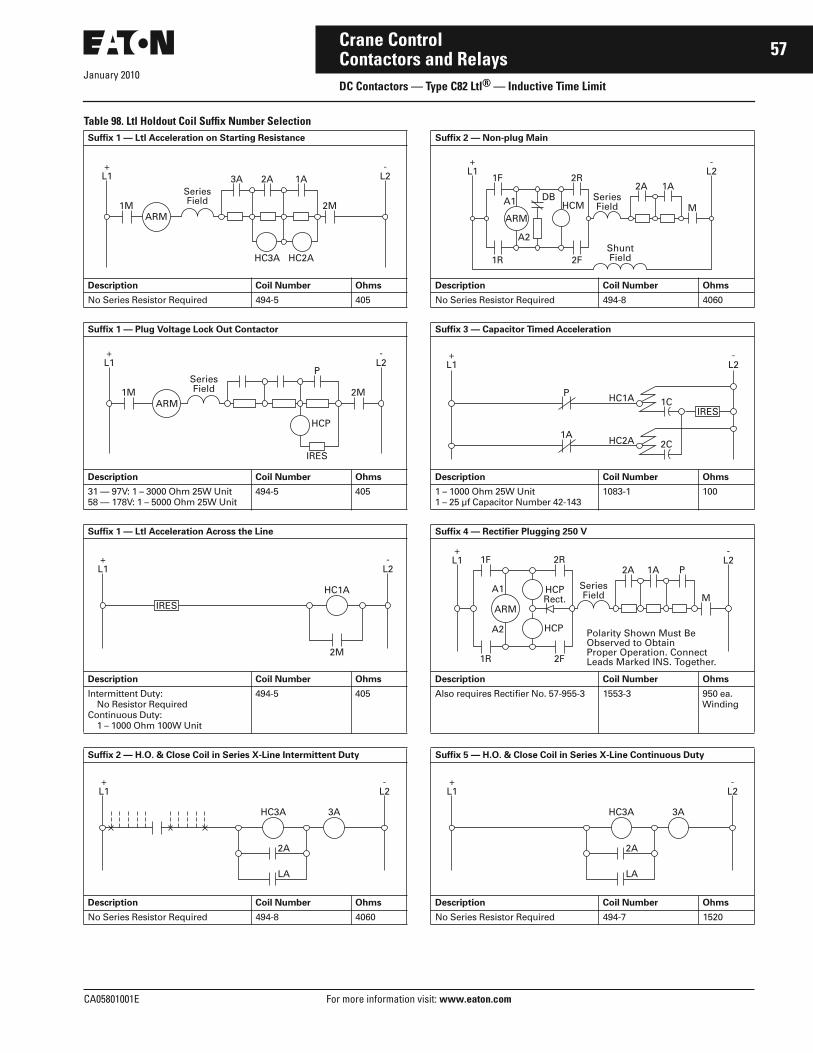
January 2010
CA05801001E For more information visit: www.eaton.com
57Crane ControlContactors and RelaysDC Contactors — Type C82 Ltl® — Inductive Time Limit
Table 98. Ltl Holdout Coil Suffix Number SelectionSuffix 1 — Ltl Acceleration on Starting Resistance Suffix 2 — Non-plug Main
Description Coil Number Ohms Description Coil Number Ohms
No Series Resistor Required 494-5 405 No Series Resistor Required 494-8 4060
Suffix 1 — Plug Voltage Lock Out Contactor Suffix 3 — Capacitor Timed Acceleration
Description Coil Number Ohms Description Coil Number Ohms
31 — 97V: 1 – 3000 Ohm 25W Unit58 — 178V: 1 – 5000 Ohm 25W Unit
494-5 405 1 – 1000 Ohm 25W Unit1 – 25 μf Capacitor Number 42-143
1083-1 100
Suffix 1 — Ltl Acceleration Across the Line Suffix 4 — Rectifier Plugging 250 V
Description Coil Number Ohms Description Coil Number Ohms
Intermittent Duty: No Resistor Required
Continuous Duty: 1 – 1000 Ohm 100W Unit
494-5 405 Also requires Rectifier No. 57-955-3 1553-3 950 ea. Winding
Suffix 2 — H.O. & Close Coil in Series X-Line Intermittent Duty Suffix 5 — H.O. & Close Coil in Series X-Line Continuous Duty
Description Coil Number Ohms Description Coil Number Ohms
No Series Resistor Required 494-8 4060 No Series Resistor Required 494-7 1520
+L1
1M 2MARM
3A 2A 1A
HC3A HC2A
-L2
SeriesField
+L1
-L2
1F 2R2A 1A
M
1R 2F
A2
A1 DB
ARMHCM
SeriesField
ShuntField
+L1
ARM
-L2
1M 2MSeriesField
P
HCP
IRES
+L1
-L2
P
1A2C
1CHC1A
HC2A
IRES
+L1
-L2
IRES
HC1A
2M
+L1
-L21F 2R
2A 1A P
M
1R 2F
ARM
A1
A2 HCP
HCPRect.
SeriesField
Polarity Shown Must BeObserved to ObtainProper Operation. ConnectLeads Marked INS. Together.
+L1
-L2
HC3A 3A
2A
LA
+L1
-L2
HC3A 3A
2A
LA

January 2010
58
For more information visit: www.eaton.com CA05801001E
Crane ControlContactors and RelaysDC Contactors — Type C82 Ltl® — Inductive Time Limit
Cross-Reference to Previous Numbers
DC Ltl Contactors — Old Catalog Number Selection
Table 99. Old Catalog Numbering System
Table 100. Old/New Catalog Number Cross-Reference Ltl ContactorsOld Number Replacement
NumberDescription
Catalog Number
Size Contact Configuration
Blowout Coil Rating (Amperes)
Enclosure Catalog Number
6006H146006H156006H166006H176006H18
11111
1NO1NO1NO1NO1NO
1 2 5 10 25
OpenOpenOpenOpenOpen
C82DC1C82DC1C82DC1C82DD1C82DF1
6006H196006H206006H216006H226006H236006H24
222222
1NO1NO1NO1NO1NO1NO
— 5 10 15 25 30
OpenOpenOpenOpenOpenOpen
C82DX1C82DC1C82DD1C82DF1C82DF1C82DG1
6006H256006H266006H276006H286006H296006H30
333333
1NO1NO1NO1NO1NO1NO
— 5 10 25 50100
OpenOpenOpenOpenOpenOpen
C82EF1C82EF1C82EF1C82EF1C82EG1C82EH1
6006H316006H32
44
1NO1NO
—150
OpenOpen
C82FJ1C82FJ1
6006H33 1 1NO — Open C82DX1
6006H546006H55
55
1NO1NO
—300
OpenOpen
C82GK1C82GK1
6006H596006H60
66
1NO1NO
—600
OpenOpen
C82JL1C82JL1
6006H63 6A 1NO 810 Open C82KM1
6 0 0 6 H 2 7 B 1 0 3 1 C 2
Base ContactorNumber
6006H_ _See Table 100
Revision Code
A, B or C
Coil Voltage
100 = 100 Vdc101 = 115 Vdc103 = 230 Vdc
Ltl Holdout Coil Suffix
Choose from Table 98, Page 57.
Electrical Interlocks
See Table 101 on Page 59.
Mounting and Latch Options
SuffixCode
Type ofPanel
Application
A — No Mounting Material
H Metal Elevated — FrontConnected — Dead Back
C Metal Surface Mounted — FrontConnected — Dead Back
D Metal Surface Mounted — Rear Connected
E InsulatedMaterial
Elevated — Front Connected
F InsulatedMaterial
Surface Mounted — Front Connected
G InsulatedMaterial
Surface Mounted — Rear Connected
– — Size 2 Only — without Latch
X — Size 2 Only — with Latch

January 2010
CA05801001E For more information visit: www.eaton.com
59Crane ControlContactors and RelaysDC Contactors — Type C82 Ltl® — Inductive Time Limit
Table 101. Unit Electrical Interlock Assemblies — Ltl ContactorsDescription Location Mounting
PlateCircuit Index
NumberNumberRequired
Mounting Plate and Driver Handling SuffixNumber
Index Number
NumberRequired
Size 2 Contactors
Without Interlock — — — — 1
Unit Electrical Interlocks
SideMount
LHRHLH & RH
2NO2NO4NO
10923H7A10923H7A10923H7A
112
10923H12A10923H12A10923H12A
112
234
Size 3 – 6Contactors
Without Interlock None — — — — — 1
Unit Electrical Interlocks
Bottom RH Single 2NO 10923H2A 1 10923H20A 1 2

January 2010
60
For more information visit: www.eaton.com CA05801001E
Crane ControlContactors and RelaysDC Contactors — Types KD & KS
Product DescriptionBulletin 7400 Type KD (Normally Open Pole) and Type KS (Normally Closed Pole) contactors are designed for front-mounting directly on steel panels and require no special hardware or insula-tors. Electrical clearances are integrally designed into the devices by the use of hot-molded reinforced polyester insulators.
These dc mill type contactors are designed for heavy industry service and are suitable for use on moving machinery. The contactors listed in this section are for surface mounting on steel panels and front-of-panel wiring.
These contactors utilize dc coils. If control power is 120 Vac, the rectifier module listed on Page 44 should be used in conjunction with a 95V coil contactor.
Auxiliary contacts and mechanical interlocks for use with these contac-tors are listed Pages 61 and 62.
The contactors feature forged steel armature levers and magnet frames for superior physical strength. Self-lubricating bearings eliminate the need for lubricating the contactor. New hot-molded arc chute assemblies con-tain no asbestos and have better arc extinction characteristics for longer contact life. The short stroke armature results in a mechanical life of more than 20 million operations.
The arc chutes and magnetic blowout structures are designed to quickly absorb and dissipate the heat caused by arcing. In addition to increasing contact life, the molded arc chute offers advantages of improved mechanical life and cooling characteristics plus superior arc-tracking resistance.
Long LifeExtended operating life for Type K con-tactors results from roll action of con-tacts, and the transfer of arc to front and rear arc runners. Arc shield and blowout structure guides and dissi-pates the hot arc and provides high interrupting capacity.
Type K 50 ampere contactors are designed with a unitized head assembly front mounted with only two screws. These assemblies are available with blowout coils rated 3, 7.5, 15, 25 and 50 amperes or without blowout, and are easily changed in the field.
Type KD — NO Pole 100 Ampere
Type KS — NC Pole150 Ampere
Figure 26. Blowout Coil Effect on Arc
Coils, head assemblies, contacts, arc shields and flexible connectors are identical for all 50 ampere contactors providing lower inventory of parts. They are also the same height as dc members of the PM Relay family — ideal for wireway panel mounting.
Type KS — Normally Closed Pole ContactorsType KS contactors have similar design and construction features to Type KD normally open pole contactors with many parts duplicated. The Type KS contactor operates with a snappy positive action requiring no retarding coil, series resistor or tapped coil.
Knife-Edge Pivot DesignType K contactors feature an exclusive shrouded knife-edge pivot which excludes dirt. On 100 ampere and larger sizes, a three-edge design provides reliable adjustment and rattleproof operation. Arm weight is supported by a vertical knife in the center, while horizontal knives at both sides ensure alignment.
Convenient AccessoriesMechanical interlocks and control circuit contacts are furnished in convenient kit form along with necessary hard-ware. No special drilling is required on panels or contactors.
A line of front wired, mill-type acces-sory devices including control, timing and overload relays are available and are compatible with Type K contactors.
Contacts
Blowout Coil
Rear Arc Runner
Front ArcRunner
Direction of Arc
Arc

January 2010
CA05801001E For more information visit: www.eaton.com
61Crane ControlContactors and RelaysDC Contactors — Types KD & KS
FeaturesThirty years of continual improve-ments bring long life, low mainte-nance, interchangeable parts and the ability to “take-it” in harsh industrial environments.
■ Front connected for direct to steel mounting. Also suitable for insulated panel mounting with poke-through wiring where rear access is desirable.
■ Solid steel backplate provides maxi-mum strength and rigidity.
■ Hot molded, reinforced polyester insulators have generous electrical clearances.
■ Shrouded knife-edge pivot design excludes dirt.
■ Encapsulated coil protects against electrical and mechanical abuse. Has saddle-type pressure terminals.
■ Non-brittle, hot-molded arc shields are of tough polyester.
■ Power terminals conveniently located with incoming power termi-nal at top of contactor; outgoing terminal at bottom.
■ Designed for front mounting directly on steel panels and require no special hardware or insulators. Electrical clearances are integrally designed into the devices by the use of hot-molded, reinforced polyester insulators.
Standards and Certifications■ NEMA ICS3-441, 442, 443.■ NEMA ICS2-331.23.■ NEMA ICS2-110.05.02.■ NEMA ICS2-125.21.02.
Technical Data and Specifications■ Current Range: 5 to 900 amperes.■ Voltage: 600 Vdc.■ Operation: Magnetic.■ Mounting:
❑ Steel panel with options for insulated panels
■ Duty:❑ Continuous (for intermittent
ratings consult factory)
Table 102. Auxiliary Contact Rating —15 Amps ContinuousVoltsdc
Interrupt Amperes
Resistive Inductive
120240550
5.52.0 .66
2.21.1 .4
AccessoriesTable 103. Coil Resistor Kit — for Size 2
� Use in series with 240 V coils. Mountable on contactor base. For other size contactors, refer to local representative.
� Use in series with 120 V coils.� Order by Part Number rather than Catalog Number.
Table 104. Control Circuit Contact Kits
Figure 27. Control Circuit Contacts
Table 105. Control Circuit Contacts — Number & Locations
SupplyVolts
CatalogNumber
PartNumber �
*
600 �550 �480 �350 �150 �
KKD-354KKD-233KKD-231KKD-232KKD-235
A073-409354-0004A073-409354-0003A073-409354-0001A073-409354-0002A073-409354-0005
Control ContactArrangement
CatalogNumber
PartNumber
*
1NO1NC1NO-1NC2NO2NC
KKD-7KKD-8KKD-1KKD-2KKD-3
A074-177676-0004A074-177676-0005A074-177676-0001A074-177676-0002A074-177676-0003
ContactorAmpereRating
PowerPoles
Per Contactor When CWEqualsInches (mm)
UsableLocationsMaximum
Numberof Blocks
MaximumNumber NCContacts
50 50 50
1NO 2 2 3 (76)4 (102)5.5 (140)
1, 51, 2 or 4, 51, 2 and 4, 5
100, 150100, 150300
1NO 2 2 3.5 (89)5 (127)6 (152)
1, 51, 2 or 4, 51, 2 or 4, 5
50 50
2NO 2 2 5 (127)9 (229)
1, 2 or 4, 51, 2 and 4, 5
100150300
1NC 1 2 DoesNotApply
1, 41, 41, 4
CW
1 2 1 2 4 5
Discount Symbol . . . . . . . . . . . . . . . . . . . . . . . 18CD4* Consult Sales Office for Pricing

January 2010
62
For more information visit: www.eaton.com CA05801001E
Crane ControlContactors and RelaysDC Contactors — Types KD & KS
Table 106. Mechanical Interlock Kits �
� Mechanical interlocks not available for use with normally closed pole contactors.� Dimension CW in Figure 27.
Table 107. AC-DC Rectifier Kits � — 50/60 Hertz
� For operating contactors from ac supply voltage. One kit per contactor. Mountable on contactor base. Suitable for use with control transformer sources to 3 kVA. For larger sources, a separate isolating transformer is required, 15 VA or larger for each contactor.
Table 108. Mounting Hardware Kits — for Control Circuit Contacts
� Order by Part Number rather than Catalog Number.
NEMASize
ContactorAmp Rating
PowerPoles
Spacing BetweenContactor Center Lines Inches (mm) �
CatalogNumber
PartNumber
*
2 Up to50 Amps
1 VS 11 VS 2
4.00 (101.6) KKD-214 A074-253077
2 VS 22 VS 2
5.00 (127.0)9.00 (228.6)
KKD-215KKD-217
A074-253078A074-407281
3, 4, 5 100 VS 100100 VS 150150 VS 150
1 VS 1 3.50 (88.9) KKD-113 A074-244364
100 VS 100100 VS 150150 VS 150
1 VS 1 5.00 (127.0) KKD-114 A074-253001
300 VS 300 1 VS 1 6.00 (152.4) KKD-313 A074-250825
Contactor acVolts
Contactordc Coil Required
CatalogNumber
*
NEMA Size Power Poles
2 thru 5 1NO, 1NC or 2NO 120 95V C81EB
NEMASize
8 HourAmpere Rating
PowerPoles
CatalogNumber
PartNumber �
*
222
505050
1NO1NC2NO
KKD-14KKD-14KKD-14
A074-266421A074-266421A074-266421
3 & 43 & 4
100 & 150100 & 150
1NO1NC
KKD-10KKD-11
A074-272165-0001A074-272165-0002
55
300300
1NO1NC
KKD-12KKD-13
A074-272165-0003A074-272165-0004
Discount Symbol . . . . . . . . . . . . . . . . . . . . . . 18CD-4* Consult Sales Office for Pricing

January 2010
CA05801001E For more information visit: www.eaton.com
63Crane ControlContactors and RelaysDC Contactors — Types KD & KS
Renewal PartsTable 109. Bulletin 7400-K, 7307-KC, 7311-KFLDescription Catalog
NumberDiscountSchedule
Part Number
*
1NO-1NC Pole2NO Poles2NC Poles1NO Pole1NC Pole
KKD-1KKD-2KKD-3KKD-7KKD-8
18CD-418CD-418CD-418CD-418CD-4
A074-177676-0001A074-177676-0002A074-177676-0003A074-177676-0004A074-177676-0005
Mounting Hardware for 100 A – 150 A KDMounting Hardware for 100 A – 150 A KDMounting Hardware for 300 A KDMounting Hardware for 300 A KSMounting Hardware and Operating Equipment
KKD-10KKD-11KKD-12KKD-13KKD-14
18CD-418CD-418CD-418CD-418CD-4
A074-272165-0001A074-272165-0002A074-272165-0003A074-272165-0004A074-266421
Movable and Stationary Contacts for 50 A KD, KSAssembly Arc Shield for 50 A KD, KS50 A KD Contact Spring50 A KS Contact Spring50 A KD, KS Connector
KKD-50KKD-51KKD-52KKD-53KKD-54
15CD-215CD-215CD-215CD-215CD-2
A074-281986A074-281987A074-281988A074-281989A074-281990
Movable and Stationary Contacts 100 A KD, KSAssembly Arc Shield for 100 A, KD, KS100 A KD Contact Spring100 A KS Contact Spring100 A KD, KS Connector
KKD-100KKD-101KKD-102KKD-103KKD-104
15CD-215CD-215CD-215CD-215CD-2
A074-253067-0001A074-253067-0002A074-253067-0003A074-253067-0004A074-253067-0005
Mechanical Interlock 3-1/2" Spacing 100 A – 150 A KDMechanical Interlock 5" Spacing 100 A – 150 A KDMovable and Stationary Contacts 150 A KD-KSArc Shield 150 A KD-KSContact Spring 150 A KD
KKD-113KKD-114KKD-150KKD-151KKD-152
18CD-418CD-415CD-215CD-215CD-2
A074-244364A074-253001 A074-253068-0001A074-253068-0002A074-253068-0003
Contact Spring 150 A KSConnector 150 A KD-KSCenter Mounting Hardware 7307KCMechanical Interlock 4" Spacing 50 A KDMechanical Interlock 5" Spacing 50 A KD
KKD-153KKD-154KKD-200KKD-214KKD-215
15CD-215CD-215CD-218CD-418CD-4
A074-253068-0004A074-253068-0005A073-409357A074-253077A074-253078
Mechanical Interlock 5-1/2" Spacing 50 A KDMechanical Interlock 9" Spacing 50 A KDCoil Resistor Kit 480 V 50 A-KD and KS, 7307KCCoil Resistor Kit 350 V 50 A-KD and KS, 7307KCCoil Resistor Kit 550 V 50 A-KD and KS, 7307KC
KKD-216KKD-217KKD-231KKD-232KKD-233
18CD-418CD-418CD-418CD-418CD-4
A074-407280A074-407281A074-409354-0001A074-409354-0002A074-409354-0003
Coil Resistor Kit 600 V 50 A-KD and KS, 7307KCCoil Resistor Kit 150 V 50 A-KD and KS, 7307KCMovable and Stationary Contact Kit 300 A KD and KSAssembly Arc Shield 300 A KD and KSMovable Contact Spring 300 A KD
KKD-234KKD-235KKD-300KKD-301KKD-302
18CD-418CD-415CD-215CD-215CD-2
A073-409354-0004A073-409354-0005A074-253069-0001A074-253069-0002A074-253069-0003
Movable Contact Spring 300 A KSFlexible Connector 300 A KD and KSMechanical Interlock 6" Spacing 300 A KDHead Assembly without Blowout 50 A KD-KSHead Assembly with 3 A Blowout 50 A KD-KS
KKD-303KKD-304KKD-313KKD-510KKD-511
15CD-215CD-218CD-415CD-215CD-2
A074-253069-0004A074-253069-0005A074-250825A074-281991A074-281992
Head Assembly with 7-1/2 AHead Assembly with 15 A Blowout 50 A KD-KSHead Assembly with 25 A Blowout 50 A KD-KSHead Assembly with 50 A Blowout 50 A KD-KS
KKD-512KKD-513KKD-514KKD-515
15CD-215CD-215CD-215CD-2
A074-281993A074-281994A074-281995A074-281996
Discount Symbol . . . . . . . . . . . . . . . . . . . . . . . 18CD-4* Consult Sales Office for Pricing

January 2010
64
For more information visit: www.eaton.com CA05801001E
Crane ControlContactors and RelaysDC Contactors — Types KD & KS
Dimensions
Figure 28. Approximate Dimensions and Weights
Table 110. Approximate Dimensions and WeightsSizeAmps
Poles Dimensions in Inches (mm) Clearance Dimensions in Inches (mm) Mtg.Hole Dia.
Ship. Wt.Lbs. (kg)H W D MH MW TW A B C E F
50 1NO 6.12(155.5)
2.50(63.5)
6.25(158.8)
5.50(139.7)
2.00(50.8)
2.50(63.5)
.25 (6.35)
7.00(177.8)
1.00(25.4)
.93(23.6)
.93(23.6)
.20(5.1)
6 (2.7)
50 2NO 6.12(155.5)
4.25(108.0)
6.25(158.8)
5.50(139.7)
2.00(50.8)
4.25(108.0)
.25(6.35)
7.00(177.8)
1.00(25.4)
.93(23.6)
.93(23.6)
.20(5.1)
10 (4.5)
100, 150 1NO 13.25(336.6)
2.75(69.9)
8.00(203.2)
12.50(317.5)
2.00(50.8)
3.00(76.2)
3.00(76.20)
12.25(311.2)
2.00(50.8)
1.25(31.8)
1.37(34.8)
.34(8.6)
11 (5.0)
300 1NO 16.75(425.5)
4.00(101.6)
11.25(285.8)
15.75(400.1)
3.00(76.2)
4.00(101.6)
4.50(114.30)
16.75(425.5)
3.50(88.9)
1.00(25.4)
1.37(34.8)
.43(10.9)
26 (12)
50 1NC 8.50(215.9)
2.50(63.5)
6.25(158.8)
8.00(203.2)
2.00(50.8)
2.50(63.5)
.25(6.35)
7.00(177.8)
.37(9.4)
1.00(25.4)
— .20(5.1)
10 (4.5)
100, 150 1NC 13.25(336.6)
3.50(88.9)
9.00(228.6)
12.50(317.5)
2.50(63.5)
4.50(114.3)
3.00(76.20)
13.37(339.6)
3.12(79.3)
.87(22.1)
— .34(8.6)
13 (5.9)
300 1NC 16.75(425.5)
4.00(101.6)
11.50(292.1)
15.75(400.1)
3.00(76.2)
7.75(196.9)
4.50(114.30)
17.37(441.2)
3.25(82.6)
1.25(31.8)
— .43(10.9)
34 (15)
W
E F
MW
TWD
MH
H Side Mtd.CCCBlock
Side Mtd.CCCBlock
Clearance C Coil Removal
Clearance B Arc Shield Removal
Clearance A Arc Shield Removal
Arcing ClearanceJ, J1
ArcingClearance
G, G1

CA05801001E For more information visit: www.eaton.com
65Crane Control
January 2010Contactors and RelaysDC Contactors — Types KD & KS
Table 111. Arcing Clearance in Inches (mm)
Product SelectionWhen Ordering Specify■ Catalog Number of contactor, plus
dash (-) and Suffix Number from Coil Voltage table, Table 113. Example: A074-266407-0240.
■ Catalog Number for auxiliary con-tact(s), if required, or any other required kit, see Pages 61 and 62.
Table 112. Type KD & KS DC Contactors — 600 V
� Order contactors by Part Number rather than Catalog Number. Add Suffix for coil voltage.
Table 113. Coil Voltage Suffix
� Each contactor.� Separate resistor is required in series with the 240 V coil. Resistor is supplied separately (not
factory mounted). Order separate item from Table 103 on Page 61. For other size contactors refer to your local representative or factory.
Size Amps Poles 600 V 250 V
G J G1 J1
50 50100150300
1NO2NO1NO1NO1NO
1.50 (38.1)1.50 (38.1)1.75 (44.5)2.50 (63.5)3.50 (88.9)
7.50 (190.5) 7.50 (190.5)11.00 (279.4)11.50 (292.1)15.50 (393.7)
1.25 (31.8)1.25 (31.8)1.50 (38.1)2.00 (50.8)3.00 (76.2)
7.25 (184.2) 7.25 (184.2)10.75 (273.0)11.00 (279.4)15.25 (387.4)
50100150300
1NC1NC1NC1NC
1.50 (38.1)1.75 (44.5)2.50 (63.5)3.50 (88.9)
7.50 (190.5)12.00 (304.8)12.50 (317.5)15.75 (400.0)
1.25 (31.8)1.50 (38.1)2.00 (50.8)3.00 (76.2)
7.25 (184.2)11.75 (298.5)12.00 (304.8)15.50 (393.7)
NEMASize
8 HourOpen Rating(Amperes)
PowerPoles
BlowoutRating(Amperes)
CatalogNumber
Open Type
PartNumber �
*
2 50 1NO1NO1NO
None 3 7.5
74U12A74U12B74U12C
A074-266407A074-266406A074-266405
1NO1NO1NO
15 25 50
74U12D74U12E74U12
A074-266404A074-266403A074-266402
2NO2NO2NO
None 3 7.5
74U22A74U22B74U22C
A074-266413A074-266412A074-266411
2NO2NO2NO
15 25 50
74U22D74U22E74U22
A074-266410A074-266409A074-266408
1NC1NC
25 50
74U121E74U121
A074-266416A074-266415
3 100 1NO1NC
100100
74U1374U131
A074-253051A074-253055
4 150 1NO1NC
150150
74U1474U141
A074-253053A074-253057
5 300 1NO1NC
300300
74U1574U151
A074-253059A074-253061
Volts Contactor Size Suffix *
240120
2, 3, 4, 52, 3, 4, 5
-0240-0120
95or othervoltage
23, 45
-0095-0095-0095
�
�
�
550480350
222
-0240-0240-0240
�
�
�
Type KD — NO Pole2-Pole 50 A
Accessories . . . . . . . . . . . . . . . . . . . . . . Pages 61, 62Renewal Parts . . . . . . . . . . . . . . . . . . . . Page 63Discount Symbol . . . . . . . . . . . . . . . . . . 18CD-4
* Consult Sales Office for Pricing

January 2010
66
For more information visit: www.eaton.com CA05801001E
Crane ControlContactors and RelaysDC Timers — Static In-Line
Static In-Line Timer
Product DescriptionThese timing units are designed to be operated in series with dc contactor and/or relays coils to give acceleration timing. They are sized to handle coil current for up to a Size 8 contactor directly without need for interface relays. Timing begins when the input to the device is energized (Type E). The delay will occur with “make”. Delay on “break” is not available.
These units are available with NO or NC contacts. They are completely solid-state so there are no moving parts to arc or fail.
Technical Data and Specifications■ Voltage: 230 Vdc.■ Timing Range: 0.05 to 180 seconds.■ Operation: Electronic.■ Output Current:
❑ .75 ampere, steady state❑ 10 ampere inrush ❑ 5 mA minimum
■ Voltage Drop: 2.5V @ 1 ampere.■ Operating Temperature: -40 – 80°C.■ Storage Temperature: -40 – 85°C.■ Humidity: 95% relative.■ Mounting: Surface mount.■ Terminations:
❑ 1/4" male quick connect terminals
Dimensions
Figure 29. Approximate Dimensions in Inches (mm) and Shipping Weights
Wiring Diagrams
Figure 30. Wiring Diagrams
Product SelectionWhen Ordering Specify■ Complete Catalog Number.
Table 114. Type C84 Static In-Line Timers
.75(19.1)
1.16 (29.5)
2.00 (50.8) 1.81 (46.0)
2.50 (63.5)
1.94(49.3)
2.00(50.8)
2.94(74.7)
3.50(88.9)
2 Mounting Holes.19 (4.8) Dia.
.25 (6.4)QuickConnectTerminals
C84AA – NO TypeShipping Weight — .13 lbs. (.06 kg)
C84AB – NC TypeShipping Weight — .13 lbs. (.06 kg)
Input
Normally Open C84AA Normally Closed C84AB
1
3
2
1 8
574
4
5+
–
Input
+ –
Load
Load
The Load May Be Locatedin Either Side of the Line
The Load May Be Locatedin Either Side of the Line
Timing Range CatalogNumber
*
NO Type, Adjustable Range.05 to 3.0 Seconds.5 to 60 Seconds
2.0 to 180 Seconds
C84AA003C84AA060C84AA180
NC Type, Adjustable Range.1 to 5.0 Seconds C84AB005
Discount Symbol . . . . . . . . . . . . . . . . . . . . . . 18CD-4* Consult Sales Office for Pricing

January 2010
CA05801001E For more information visit: www.eaton.com
67Crane ControlContactors and RelaysLow Voltage Monitoring Relays
Low Voltage Monitoring Relay
Product DescriptionThe Low Voltage Monitoring Relay (LVMR) is designed specifically to address power loss during hoist lower-ing (regeneration) operation. The LVMR continuously monitors bus volt-age and de-energizes the UV relay if the bus voltage falls below a value that will safely operate contactors and relays.
The LVMR distinguishes the difference between main power and regeneration power produced by a motor. It con-stantly monitors the dc bus voltage and sets the series brake automatically when it detects a power loss condition. When the voltage drops below the point where relays or contactors can reliably pick up and seal (as defined by the current NEMA standards), the hoist control panel will shut down and set the brake.
InstallationInstallation requires mounting one device in your existing hoist panel and adding two wires.
■ Remove the wire lead from the existing UV coil and the last protective interlock.
■ Mount the LVMR as close as possi-ble to the existing UV relay and reconnect the removed wire to the LVMR interlock at terminal 5.
■ Add a wire from the other side of the LVMR interlock, terminal 6, to the original UV coil terminal. Using the supplied terminal lug, connect a wire from terminal 4 on the elec-tronic module to L2 on the other side of the UV coil.
Technical Data andSpecifications■ Voltage Input Range: 230 – 270 Vdc.■ Ambient Temperature Range:
❑ 0 – 65°C■ Pickup Adjustment: 180 – 200 Vdc.■ Reaction Time: 40 milliseconds.■ Relay Contact Current Rating:
❑ 1.1 amp dc inductive at 230 Vdc■ Number of Contacts: 2.
Dimensions
Figure 31. Approximate Dimensions in Inches (mm)
Wiring Diagram
Figure 32. Low Voltage Monitoring Relay Diagram
Product SelectionWhen Ordering Specify■ Complete Catalog Number.
Table 115. Low Voltage Monitoring Relay
3.38(85.9)
6(152.4)
6.25(158.8)
8(203.2)
LSR 1OL 2OL
L2(-)L1(+)
2 1
3 4
+ -
6 5
UV
LVMR
CKS
CFU15A
CFU15A
LVMR
CKS
Description CatalogNumber
*
Low Voltage Monitoring Relay
6011ED5
Discount Symbol . . . . . . . . . . . . . . . . . . . . . . . 18CD-4* Consult Sales Office for Pricing

January 2010
68
For more information visit: www.eaton.com CA05801001E
Crane ControlContactors and RelaysDC Relays — Heavy-Duty Mill
8 Circuit Relay
Product DescriptionThese dc Mill Type Relays are designed for heavy industry service and are suitable for use on moving machinery. They are arranged for steel panel mounting with front connec-tions. Unit circuit blocks have two captive mounting screws and are inter-changeable between relays. They are easily convertible from normally open to normally closed or vice versa. Contacts are of double break design.
Standards and Certifications■ NEMA ICS3-212.20.21.■ NEMA ICS2-125.21.02.
Technical Data and Specifications■ Voltage: 115, 230 Vdc.■ Operation: Magnetic.■ Mounting: Steel panel.■ Electrical Ratings:
❑ 10 amperes continuous❑ 2.2 amperes inductive breaking
at 115 V❑ 1.1 amperes inductive breaking
at 230 V
Dimensions
Figure 33. Approximate Dimensions in Inches (mm)
Table 116. Approximate Dimensions in Inches (mm)
Product SelectionWhen Ordering Specify■ Catalog Number of relay.■ Catalog Number of unit circuit block(s), if required.
Table 117. Relays — 230 Vdc Coil
� To order 115 Vdc coil, substitute Suffix Number 101 for 103 in above listed Catalog Number. Example: 6011H23-101-1.
Table 118. Unit Circuit Blocks
� When mounting circuit blocks, DO NOT exceed maximum capacity of relay frame.
CircuitCapacity ofRelay
NumberofCircuits
WideA
HighB
DeepC
MountingE
4 Circuits 1 to 4 3.38 (85.9) 8.00 (203.2) 6.00 (152.4) 6.25 (158.8)
8 Circuits 1 to 45 to 8
5.00 (127.0)5.00 (127.0)
8.38 (212.9)8.38 (212.9)
5.75 (146.1)7.38 (187.5)
7.75 (196.9)7.75 (196.9)
Maximum CircuitCapacity of Relay Frame
Number ofCircuits Assembled
Catalog Number �
*
4(2 Double Circuit Blocks)
04NO
6011H23-103-16011H23-103-15
8(4 Double Circuit Blocks)
08NO
6011H2-103-16011H2-103-27
A C
EB
Mounting Screws Included �
Circuit Arrangement
Catalog Number
*
1NO1NC1NO-1NC2NO2NC
6011H46011H56011H66011H76011H8
Discount Symbol . . . . . . . . . . . . . . . . . . . . . . 18CD-4* Consult Sales Office for Pricing

January 2010
CA05801001E For more information visit: www.eaton.com
69Crane ControlContactors and RelaysDC Relays — Magnetic Overload
Cat. No. C304ANA301
Product DescriptionThese overload relays are designed for use on dc power circuits to monitor dc motor loading. Inverse time and instantaneous versions are available, with either manual or automatic reset.
Inverse time limit trip relays are nor-mally set to trip between 125% and 175% of full load motor current. The inverse time feature is provided by an oil dashpot.
Note: These inverse trip type overload relays are shipped with a neophrene plug in the dashpot to prevent mechanical damage during shipment. This plug must be removed for the relay to function properly.
Instantaneous trip type overload relays use a dry type dashpot and are normally set to trip between 200% and 300% of full load motor current.
Standards and Certifications■ NEMA ICS2-222.■ ANSI/IEEE Standard 100.■ NEMA Standard 5-24-1960.
Technical Data and Specifications■ Current Range: 1.5 – 6500 amperes.■ Voltage: Maximum 600 Vdc.■ Operation:
❑ Magnetic with oil filled dashpot for time delay
■ Mounting: ❑ Steel panel or insulated panel
■ Electrical Ratings:❑ 10 amperes continuous❑ 2.2 amperes inductive breaking
at 115 V❑ 1.1 amperes inductive breaking
at 230 V■ Reset: Manual or automatic.
Dimensions
Figure 34. Approximate Dimensions in Inches (mm)
Table 119. Types C304AN – DN �
� Type C304EN dimensions available upon request.
CatalogType
Dimensions inInches (mm)
A
C304ANC304BNC304CNC304DN
5.00 (127.0)5.38 (136.7)5.75 (146.1)6.75 (171.5)
A
Types C304AN – DN �Automatic Reset
Types C304AN – DN �Manual Reset
8.72(221.5) 6.5
(165.1)
5.56(141.2)
2 Mtg. Holes for 1/4-20 Screws
A
8.72(221.5)
6.5(165.1)
6.94(176.3)
2 Mtg. Holes for 1/4-20 Screws

January 2010
70
For more information visit: www.eaton.com CA05801001E
Crane ControlContactors and RelaysDC Relays — Magnetic Overload
Catalog Number SelectionTable 120. DC Magnetic Overload Relay Catalog Numbering System
Product SelectionWhen Ordering Specify■ Complete Catalog Number.
Table 121. Inverse Time Limit Trip Type — Automatic Reset �
� For relays with manual reset, change 8th digit of listed Catalog Number from 1 to 2. Example: C304ANA201.
Motor Full LoadCurrent Range Amperes
Calibration PlateCurrent RangeAmperes
Catalog Number *
Steel PanelFront Connected
2.9 – 4.5 4.0 – 6.2 5.6 – 9.0 6.6 – 12.3 10.0 – 18.5
3.5 – 8.0 5.0 – 11.0 7.0 – 16.0 9.0 – 21.0 15.0 – 30.0
C304ANA101C304ANA102C304ANA103C304ANA104C304ANA105
15.2 – 28.0 20.0 – 37.0 30.8 – 57.0
20.0 – 50.0 30.0 – 60.0 40.0 – 100.0
C304ANA106C304ANA107C304ANA108
38. – 71. 62. – 114. 100. – 185.
50. – 125. 80. – 200. 150. – 300.
C304BNA109C304BNA110C304BNA111
160. – 297. 266. – 495. 400. – 742.
200. – 500. 350. – 850. 500. – 1300.
C304CNA112C304CNA113C304CNA114
470. – 874. 800. – 1485.
600. – 1500.1000. – 2500.
C304DNA115C304DNA116
1200. – 2285. 1500. – 3900. C304ENA117
C 3 0 4 A N A 1 O 1
Stud and Coil Types
A = 3/8" Stud, Wire Wound CoilB = 3/8" Stud, Bar Wound CoilC = 1/2" Stud, Bar Wound CoilD = 3/4" Stud, Bar Wound CoilE = 3/4" Stud, Horseshoe Type
Open
Trip and Reset Type
1 = Inverse Time Limit, Auto Reset2 = Inverse Time Limit, Manual Reset3 = Instantaneous, Auto Reset4 = Instantaneous, Manual Reset
Panel Type and Connection
A = Steel Panel, Front Connected
Coil Current Rating
01
BaseCatalog Number
C304
Discount Symbol . . . . . . . . . . . . . . . . . . . . . . 18CD-4* Consult Sales Office for Pricing

January 2010
CA05801001E For more information visit: www.eaton.com
71Crane ControlContactors and RelaysDC Relays — Magnetic Overload
Table 122. Instantaneous Trip Type — Automatic Reset �
� For relays with manual reset, change 8th digit of listed Catalog Number from 3 to 4. Example: C304ANA401.
Table 123. Stud and Coil Types
Motor Full LoadCurrent RangeAmperes
Calibration PlateCurrent RangeAmperes
Catalog Number *
Steel PanelFront Connected
1.5 – 2.6 2.3 – 4.0 3.1 – 5.3 4.2 – 7.2 6.2 – 10.8
3.5 – 8.0 5.0 – 11.0 7.0 – 16.0 9.0 – 21.0 15.0 – 30.0
C304ANA301C304ANA302C304ANA303C304ANA304C304ANA305
9.5 – 16.6 12.5 – 21.0 19.0 – 33.0
20.0 – 50.0 30.0 – 60.0 40.0 – 100.0
C304ANA306C304ANA307C304ANA308
24.0 – 41.0 39.0 – 67.0 63.0 – 108.0
50.0 – 125.0 80.0 – 200.0 150.0 – 300.0
C304BNA309C304BNA310C304BNA311
100.0 – 173.0 166.0 – 289.0 250.0 – 433.0
200.0 – 500.0 350.0 – 850.0 500.0 – 1300.0
C304CNA312C304CNA313C304CNA314
294.0 – 510.0 500.0 – 866.0
600.0 – 1500.01000.0 – 2500.0
C304DNA315C304DNA316
750.0 – 1300.01250.0 – 2166.0
1500.0 – 3900.03800.0 – 6500.0
C304ENA317C304ENA318
Catalog Type Description Dimension Drawing Number
Automatic Reset Manual Reset
C304ANC304BNC304CNC304DNC304EN
3/8" Stud, Wire Wound Coil3/8" Stud, Bar Wound Coil1/2" Stud, Bar Wound Coil3/4" Stud, Bar Wound Coil3/4" Stud, Horseshoe Type
B10-3949B10-3949B10-3949B10-3949A10-4135
B10-3951B10-3951B10-3951B10-3951A10-4136
Discount Symbol . . . . . . . . . . . . . . . . . . . . . . . 18CD-4* Consult Sales Office for Pricing

January 2010
72
For more information visit: www.eaton.com CA05801001E
Crane ControlContactors and RelaysDC Relays — Magnetic Overload
Cross-Reference to Previous ProductsTable 124. DC Magnetic Overload Relays Cross-Reference
� New device has a wider calibration range than old device, but is a functional replacement.
Note: See Pages 70 and 71 for prices.
Old New Old New Old New Old New
10165H1-2-3210165H1-2-3410165H1-3-3210165H1-3-3410165H1-4-32
C304ANA102C304AND102C304ANA103C304AND103C304ANA104
10165H2-3-3410165H2-4-3210165H2-4-3410165H2-5-3210165H2-5-34
C304AND203C304ANA204C304AND204C304ANA205C304AND205
10165H3-5-3410165H3-6-3210165H3-6-3410165H3-7-3210165H3-7-34
C304AND306C304ANA307C304AND307C304ANA308C304AND308
10165H4-4-3210165H4-4-3410165H4-5-3210165H4-5-3410165H4-6-32
C304ANA405C304AND405C304ANA406C304AND406C304ANA407
10165H1-4-3410165H1-5-3210165H1-5-3410165H1-6-3210165H1-6-34
C304AND104C304ANA105C304AND105C304ANA106C304AND106
10165H2-6-3210165H2-6-3410165H2-7-3210165H2-7-3410165H2-8-32
C304ANA206C304AND206C304ANA207C304AND207C304ANA208
10165H3-9-1210165H3-9-1910165H3-12-1910165H3-13-1410165H3-13-20
C304BND311C304BNA311C304CNA313C304CND313 �
C304CNA313 �
10165H4-6-3410165H4-7-3210165H4-7-3410165H4-9-1210165H4-9-19
C304AND407C304ANA408C304AND408C304BND411C304BNA411
10165H1-7-3210165H1-7-3410165H1-8-3210165H1-8-3410165H1-9-12
C304ANA107C304AND107C304ANA108C304AND108C304BND110
10165H2-8-3410165H2-9-1210165H2-9-1910165H2-10-1210165H2-10-19
C304AND208C304BND210C304BNA210C304BND211C304BNA211
10165H3-14-1410165H3-14-2010165H3-15-1610165H3-15-2110165H3-16-16
C304CND314 �
C304CNA314 �
C304DND315 �
C304DNA315 �
C304DND315 �
10165H4-13-1410165H4-13-2010165H4-14-1410165H4-14-2010165H4-15-16
C304CND414 �
C304CNA413 �
C304CND414 �
C304CNA414 �
C304DND415 �
10165H1-9-1910165H1-10-1210165H1-10-1910165H1-11-1910165H1-12-14
C304BNA110C304BND111C304BNA111C304CNA112C304CND112
10165H2-12-1410165H2-12-2010165H2-15-1610165H2-15-2110165H2-27-16
C304CND212C304CNA212C304DND215 �
C304DNA215 �
C304DND215 �
10165H3-16-2110165H3-17-2310165H3-17-2510165H3-20-3210165H3-20-34
C304DNA315 �
C304DNA316 �
C304DND316 �
C304ANA306C304AND306
10165H4-15-2110165H4-16-1610165H4-16-2110165H4-17-2310165H4-17-25
C304DNA415 �
C304DND415 �
C304DNA415 �
C304DNA416 �
C304DND416 �
10165H1-12-2010165H1-15-1610165H1-15-2110165H1-27-1610165H1-27-21
C304CNA112C304DND115 �
C304DNA115 �
C304DND115 �
C304DNA115 �
10165H2-27-2110165H2-29-3210165H2-29-3410165H2-37-1210165H2-37-19
C304DNA215 �
C304ANA201C304AND201C304BND209C304BNA209
10165H3-26-1410165H3-26-2010165H3-27-1410165H3-27-2010165H3-31-32
C304CND313 �
C304CNA313 �
C304CND314 �
C304CNA314 �
C304ANA301
10165H4-20-3210165H4-20-3410165H4-26-1410165H4-26-2010165H4-27-14
C304ANA406C304AND406C304CND413 �
C304CNA413 �
C304CND414 �
10165H1-29-3210165H1-29-3410165H1-37-1210165H1-37-1910165H1-42-16
C304ANA101C304AND101C304BND109C304BNA109C304DND115 �
10165H2-42-1610165H2-42-2110165H2-43-1610165H2-43-2710165H2-47-16
C304DND215 �
C304DNA215 �
C304DND215 �
C304DNA215 � C304DND215 �
10165H3-31-3410165H3-32-3210165H3-32-3410165H3-38-1210165H3-38-19
C304AND301C304ANA302C304AND302C304BND310C304BNA310
10165H4-27-2010165H4-31-3210165H4-31-3410165H4-32-3210165H4-32-34
C304CNA414 �
C304ANA401C304AND401C304ANA402C304AND402
10165H1-42-2110165H1-43-1610165H1-43-2710165H1-47-1610165H1-47-27
C304DNA115 �
C304DND115 �
C304DNA115 �
C304DND115 �
C304DNA115 �
10165H2-47-2710165H2-48-1610165H2-48-2710165H3-2-3210165H3-2-34
C304DNA215 �
C304DND216 �
C304DNA216 �
C304ANA303C304AND303
10165H3-47-1610165H3-47-2710165H3-48-1610165H3-48-2710165H3-53-23
C304DND316 �
C304DNA316 �
C304DND316 �
C304DNA316 �
C304DNA316 �
10165H3-38-1210165H3-38-1910165H4-47-1610165H4-47-2710165H4-48-16
C304BND410C304BNA410C304DND416 �
C304DNA416 �
C304DND416 �
10165H1-48-1610165H1-48-2710165H2-2-3210165H2-2-3410165H2-3-32
C304DND116 �
C304DNA116 �
C304ANA202C304AND202C304ANA203
10165H3-3-3210165H3-3-3410165H3-4-3210165H3-4-3410165H3-5-32
C304ANA304C304AND304C304ANA305C304AND305C304ANA306
10165H3-53-2510165H4-2-3210165H4-2-3410165H4-3-3210165H4-3-34
C034DND316 �
C304ANA403C304AND403C304ANA404C304AND404
10165H4-48-2710165H4-53-2310165H4-53-25——
C304DNA416 �
C304DNA416 �
C304DND416 �
——

January 2010
CA05801001E For more information visit: www.eaton.com
73Crane ControlContactors and RelaysDC Relays — Magnetic Overload
Table 125. DC Magnetic Overload Relays Cross-Reference with Old Style NumberOld Catalog Number
Old Style Number
Replacement C304 Catalog Number
Old Catalog Number
Old Style Number
Replacement C304 Catalog Number
28UI2-228UI2-328UI2-528UI2-628UI2-8
A073-260365-4001A073-260365-4002A073-260365-4003A073-260365-4004A073-260365-4005
C304ANA401C304ANA402C304ANA403C304ANA404C304ANA405
28UI3-228UI3228UI3-328UI3-528UI3-6
A073-260365-2001A073-260365-2002A073-260365-2003A073-260365-2004A073-260365-2005
C304ANA301C304ANA302C304ANA303C304ANA304C304ANA305
28UI2-1328UI2-2028UI2-2228UI2-3528UI2-55
A073-260365-4006A073-260365-4007A073-260365-4008A073-260365-4009A073-260365-4010
C304ANA406C304ANA407C304ANA407C304ANA408C304BNA409
28UI3-1328UI3-2028UI3-2228UI3-3528UI3-55
A073-260365-2006A073-260365-2007A073-260365-2008A073-260365-2009A073-260365-2010
C304ANA306C304ANA307C304ANA307C304ANA308C304BNA309
28UI2-6828UI2-10028UI2-11028UI2-16028UI2-220
A073-260365-4011A073-260365-4012A073-260365-4013A073-260365-4014A073-260365-4015
C304BNA410C304BNA411C304BNA411C304CNA412C304CNA413
28UI3-6828UI3-10028UI3-11028UI3-16028UI3-220
A073-260365-2011A073-260365-2012A073-260365-2013A073-260365-2014A073-260365-2015
C304BNA310C304BNA311C304BNA311C304CNA312C304CNA313
28UI2-28528UI2-50028UI2-60028UI2-90028UI2-1500
A073-260365-4016A073-260365-4017A073-260365-4018A073-260365-4019A073-281375-0004
C304CNA414C304CNA414C304DNA415C304DNA416C304ENA417
28UI3-28528UI3-50028UI3-60028UI3-90028UI3-1500
A073-260365-2016A073-260365-2017A073-260365-2018A073-260365-2019A073-281375-0002
C304CNA314C304CNA314C304DNA315C304DNA316C304ENA317
28UI2-280028UT2-228UT2-328UT2-528UT2-6
A073-281376-0004A073-260365-3001A073-260365-3002A073-260365-3003A073-260365-3004
C304ENA418C304ANA201C304ANA201C304ANA201C304ANA202
28UI3-280028UT3-228UT3-328UT3-528UT3-6
A073-281376-0002A073-260365-1001A073-260365-1002A073-260365-1003A073-260365-1004
C304ENA318C304ANA101C304ANA101C304ANA101C304ANA102
28UT2-828UT2-1328UT2-2028UT2-2228UT2-35
A073-260365-3005A073-260365-3006A073-260365-3007A073-260365-3008A073-260365-3009
C304ANA203C304ANA204C304ANA205C304ANA205C304ANA206
28UT3-828UT3-1328UT3-2028UT3-2228UT3-35
A073-260365-1005A073-260365-1006A073-260365-1007A073-260365-1008A073-260365-1009
C304ANA103C304ANA104C304ANA105C304ANA105C304ANA106
28UT2-5528UT2-6828UT2-10028UT2-11028UT2-160
A073-260365-3010A073-260365-3011A073-260365-3012A073-260365-3013A073-260365-3014
C304ANA207C304ANA208C304BNA209C304BNA210C304BNA211
28UT3-5528UT3-6828UT3-10028UT3-11028UT3-160
A073-260365-1010A073-260365-1011A073-260365-1012A073-260365-1013A073-260365-1014
C304ANA107C304ANA108C304BNA109C304BNA110C304BNA111
28UT2-22028UT2-28528UT2-50028UT2-60028UT2-90028UT2-150028UT2-2800
A073-260365-3015A073-260365-3016A073-260365-3017A073-260365-3018A073-260365-3019A073-281375-0003A073-281376-0003
C304CNA212C304CNA212C304CNA213C304CNA214C304DNA215C304DNA216C304ENA217
28UT3-22028UT3-28528UT3-50028UT3-60028UT3-90028UT3-150028UT3-2800
A073-260365-1015A073-260365-1016A073-260365-1017A073-260365-1018A073-260365-1019A073-281375-0001A073-281376-0001
C304CNA112C304CNA112C304CNA113C304CNA114C304DNA115C304DNA116C304ENA117

January 2010
74
For more information visit: www.eaton.com CA05801001E
Crane ControlContactors and RelaysDC Relays — Field Control
DC Field Loss Relay
Product DescriptionThis family of motor field control relays consists of a relay with 1NO pole (#901) and a relay with 1NC pole (#902).
These relays are used on a large num-ber of applications requiring either an NO or NC control contact. The opening and closing of the contact is respon-sive to changes in current through the coil. The relays are equipped with one or two coils, depending on the applica-tion. When the relays leave the factory, they are adjusted for average load conditions.
This adjustment is made up of two parts:
1. The adjustment of the differential, which is the difference between the opening and closing setting, and
2. The adjustment of the range or operating values.
Standards and Certifications■ NEMA Standard 5-24-1960.■ NEMA Standard 5-29-1960.■ NEMA Standard 1-5-1977.
Technical Data and Specifications■ Current Range: 5.6 – 1350 amperes.■ Voltage: Maximum 600 Vdc.■ Operation: Magnetic.■ Mounting:
❑ Steel panel or insulated panel■ Contact Ratings:
❑ 5 amperes at 240 V❑ 10 amperes at 120 V
■ Duty: Continuous.■ Panel Space Required — without
Studs for Coils:❑ Approximately 2.75 x 7.44"
(69.9 x 189.0 mm)■ Approximate Weight:
❑ Relay with one coil — 5 lb. (2.3 kg)❑ Relay with two coils, with B.O. —
6.5 lb. (3.0 kg)
Product SelectionWhen Ordering Specify
Field Loss Relays
■ Maximum and minimum field amperes.
■ Field ohms.
Accelerating and Decelerating Relays
■ Motor horsepower.■ Motor full load amperes.■ Voltage.■ Maximum field current.■ Field accelerating or field decelerating
relay.
Voltage Relays
■ Desired pick-up voltage.■ Desired drop-out voltage.■ Maximum voltage seen by device.
OR
Supply complete Serial Number of controller where relay is used, plus diagram designation of relay required. Relays must be supplied with coils.
Table 126. PricingRelay Type *
Single CoilDouble Coil
With Blowout Coil
Discount Symbol . . . . . . . . . . . . . . . . . . . . . . 18CD-4* Consult Sales Office for Pricing

January 2010
CA05801001E For more information visit: www.eaton.com
75Crane ControlContactors and RelaysDC Relays — Type KC — Heavy-Duty Mill
Basic 4-Contact Type KC Relay
Product DescriptionThe Type KC line of control relays com-plements the mill-type, front connected DC contactors (Bulletin 7400, Type K). Each device is completely assembled and ready for mounting on metal panels without additional insulators or special hardware.
These dc mill type relays are designed for heavy industry service and are suitable for use on moving machinery. They are arranged for steel panel mounting with front connections. Unit circuit blocks have two captive mounting screws and are interchange-able between relays. They are easily convertible from normally open to normally closed or vice versa. Visible contacts are of double break design.
Contact ConversionThe fully visible contacts have NEMA ICS-2-125 heavy-duty interrupting ratings and are easily converted in the field using just a screwdriver as illus-trated in Figure 35. Pressure terminals
permit quick installation of up to two #12 wires, solid or stranded, per terminal. The molded operating coils provide maximum protection against moisture and mechanical abuse.
Figure 35. Contact Conversion
Features■ Contacts are easily field convertible
from NO to NC operation and vice versa.
■ Melamine molded contact blocks feature wear-resistant nylon guides and stainless steel springs.
■ Retained knife-edge design for reliable alignment.
■ Contacts rated 15 amperes continuous.
■ No adjustments to maintain — armature spring and air gap are fixed.
■ Encapsulated coils feature pressure type saddle terminals.
■ Basic relays are available with 2, 4, 6 or 8 contacts.
■ All relays in the line have same mounting dimensions.
Standards and Certifications■ NEMA ICS3-212.20.21.■ NEMA ICS2-125.21.02.
Technical Data and Specifications■ Voltage: 600 Vdc maximum.■ Operation: Magnetic.■ Mounting: Steel panel.■ Electrical Ratings:
❑ 15 amperes continuous❑ 2.2 amperes inductive breaking
at 115 V❑ 1.1 amperes inductive breaking
at 230 V
Slide Movable Contact Out Flip Over and Insert Contact
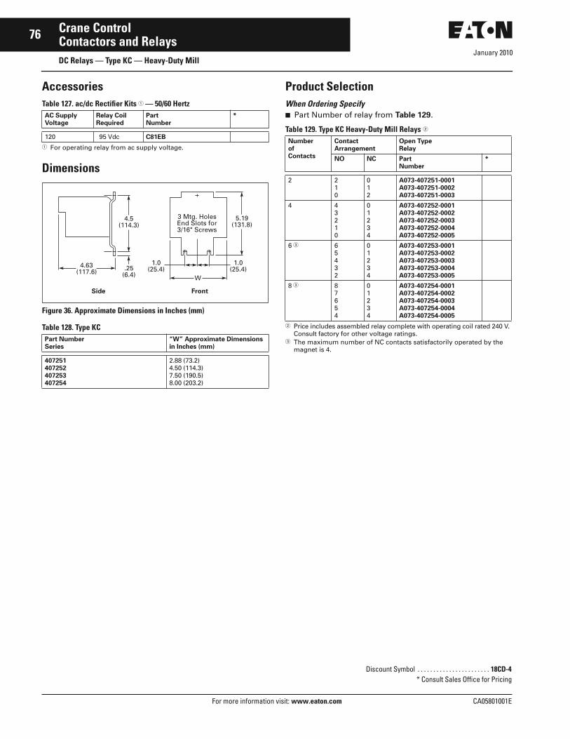
January 2010
76
For more information visit: www.eaton.com CA05801001E
Crane ControlContactors and RelaysDC Relays — Type KC — Heavy-Duty Mill
AccessoriesTable 127. ac/dc Rectifier Kits � — 50/60 Hertz
� For operating relay from ac supply voltage.
Dimensions
Figure 36. Approximate Dimensions in Inches (mm)
Table 128. Type KC
Product SelectionWhen Ordering Specify■ Part Number of relay from Table 129.
Table 129. Type KC Heavy-Duty Mill Relays �
� Price includes assembled relay complete with operating coil rated 240 V. Consult factory for other voltage ratings.
� The maximum number of NC contacts satisfactorily operated by the magnet is 4.
AC SupplyVoltage
Relay CoilRequired
PartNumber
*
120 95 Vdc C81EB
Part Number Series
“W” Approximate Dimensions in Inches (mm)
407251407252407253407254
2.88 (73.2)4.50 (114.3)7.50 (190.5)8.00 (203.2)
4.63(117.6)
W
5.19(131.8)
4.5(114.3)
.25(6.4)
1.0(25.4)
1.0(25.4)
FrontSide
3 Mtg. HolesEnd Slots for3/16" Screws
Discount Symbol . . . . . . . . . . . . . . . . . . . . . . . 18CD-4* Consult Sales Office for Pricing
NumberofContacts
ContactArrangement
Open TypeRelay
NO NC Part Number
*
2 210
012
A073-407251-0001A073-407251-0002A073-407251-0003
4 43210
01234
A073-407252-0001A073-407252-0002A073-407252-0003A073-407252-0004A073-407252-0005
6 � 65432
01234
A073-407253-0001A073-407253-0002A073-407253-0003A073-407253-0004A073-407253-0005
8 � 87654
01234
A073-407254-0001A073-407254-0002A073-407254-0003A073-407254-0004A073-407254-0005

January 2010
CA05801001E For more information visit: www.eaton.com
77Crane ControlContactors and RelaysDC Relays — Types KPR & KFL — Special Application
DC Plugging Relay
Product Description
Type KPR PluggingThe Type KPR Relay features a diode assembly mounted on the relay base and wired in series with the relay oper-ating coil. The relay detects when a dc motor is being plugged. (Plugging is the sudden reversal of the polarity applied to a relay motor causing it to rapidly stop and reverse rotational direction.)
The coil circuit of the plugging relay is connected to parallel with the motor armature and monitors armature volt-age. During normal dc motor opera-tion, the diode is non-conducting and the relay is de-energized. During motor plugging, polarity reverses, causing the diode to conduct and operate the relay. The contacts of the relay cause motor circuit contactors and resistors to properly plug the motor.
Type KFL Field LossThe Type KFL relays are no longer manufactured. The suggested replace-ment is the Type 901 single-pole normally open relay. Refer to Page 74 for application and ordering information.
Standards and Certifications■ NEMA Standard 5-24-1960.■ NEMA Standard 5-29-1960.■ NEMA Standard 1-5-1977.
Technical Data and Specifications■ Voltage: Maximum 600 Vdc.■ Operation: Magnetic.■ Mounting:
❑ Steel panel or insulated panel
■ Contact Ratings:❑ 5 amperes at 240 V❑ 10 amperes at 120 V
■ Duty: Continuous.
Dimensions
Figure 37. Approximate Dimensions in Inches (mm)
Table 130. Type KPR Plugging
Product SelectionWhen Ordering Specify■ Complete Catalog or Part Number
Table 131. Type KPR Plugging Relay (Open Type)
� KPR-2 relays are for 2-step or graduated plugging. Consult factory for application details.
Description Approximate Dimensions in Inches (mm)
W T
Type KPR-1 Relay 3.25 (82.6) —
Type KPR-2 Relay 2.87 (72.9) 2.75 (69.9)
Motor Voltage
Relay Type
Catalog Number
*
240 Vdc550 Vdc
KPR-1KPR-1
7311UD-2407311UD-550
240 Vdc550 Vdc
KPR-2 �KPR-2 �
7311UE-2407311UE-550
4.63(117.6)
W
5.19(131.8)
4.5(114.3)
T
.25(6.4)
1.0(25.4)
1.0(25.4)
SideFront
Approximate Weight — 12 lbs. (5.4 kg)
3 Mtg. Holesand Slots for3/16" Screws
Discount Symbol . . . . . . . . . . . . . . . . . . . . . . . 18CD-4* Consult Sales Office for Pricing

January 2010
78
For more information visit: www.eaton.com CA05801001E
Crane ControlContactors and RelaysDC Timing Relays — 7313 VTH & 7313 CTH
Timing Relay Replacement
Product DescriptionThe replacement Type 7313 heavy-duty DC relays provide adjustable ON-delay timing factory set to duplicate the time delay provided by the previous type CTH and VTH timers. These relays are supplied with equivalent pilot duty contact ratings and configuration.
Product SelectionTable 132. Challenger Bulletin 7313 VTH Timing Relay Data (Sorted by Old Part Number) Contacts Timing
(Seconds)OldPart Number
NewPart Number
*
2NO2NO2NO2NO2NO2NO2NO2NO2NO
.25 .50 .75 1.0 2.0 3.0 4.0 6.010.0
A073-260931-1001A073-260931-1002A073-260931-1003A073-260931-1004A073-260931-1006A073-260931-1007A073-260931-1008A073-260931-1010A073-260931-1013
7313ED17313ED17313ED17313ED17313ED17313ED17313ED27313ED27313ED2
1NO/1NC1NO/1NC1NO/1NC1NO/1NC1NO/1NC1NO/1NC1NO/1NC1NO/1NC1NO/1NC
.25 .50 .75 1.0 2.0 3.0 4.0 6.010.0
A073-260931-2001A073-260931-2002A073-260931-2003A073-260931-2004A073-260931-2006A073-260931-2007A073-260931-2008A073-260931-2010A073-260931-2013
7313ED37313ED37313ED37313ED37313ED37313ED37313ED47313ED47313ED4
2NC2NC2NC2NC2NC2NC2NC2NC2NC
.25 .50 .75 1.0 2.0 3.0 4.0 6.010.0
A073-260931-3001A073-260931-3002A073-260931-3003A073-260931-3004A073-260931-3006A073-260931-3007A073-260931-3008A073-260931-3010A073-260931-3013
7313ED57313ED57313ED57313ED57313ED57313ED57313ED67313ED67313ED6
4NO4NO4NO4NO4NO4NO4NO4NO4NO
.25 .50 .75 1.0 2.0 3.0 4.0 6.010.0
A073-260931-4001A073-260931-4002A073-260931-4003A073-260931-4004A073-260931-4006A073-260931-4007A073-260931-4008A073-260931-4010A073-260931-4013
7313ED77313ED77313ED77313ED77313ED77313ED77313ED87313ED87313ED8
3NO/1NC3NO/1NC3NO/1NC3NO/1NC3NO/1NC3NO/1NC3NO/1NC3NO/1NC3NO/1NC
.25 .50 .75 1.0 2.0 3.0 4.0 6.010.0
A073-260931-5001A073-260931-5002A073-260931-5003A073-260931-5004A073-260931-5006A073-260931-5007A073-260931-5008A073-260931-5010A073-260931-5013
7313ED97313ED97313ED97313ED97313ED97313ED97313ED107313ED107313ED10
2NO/2NC2NO/2NC2NO/2NC2NO/2NC2NO/2NC2NO/2NC2NO/2NC2NO/2NC2NO/2NC
.25 .50 .75 1.0 2.0 3.0 4.0 6.010.0
A073-260931-6001A073-260931-6002A073-260931-6003A073-260931-6004A073-260931-6006A073-260931-6007A073-260931-6008A073-260931-6010A073-260931-6013
7313ED117313ED117313ED117313ED117313ED117313ED117313ED127313ED127313ED12
Discount Symbol . . . . . . . . . . . . . . . . . . . . . . 18CD-4* Consult Sales Office for Pricing

CA05801001E For more information visit: www.eaton.com
79Crane Control
January 2010Contactors and RelaysDC Timing Relays — 7313 VTH & 7313 CTH
Table 133. Challenger Bulletin 7313 CTH Timing Relay Data (Sorted by Old Part Number) Contacts Timing
(Seconds)OldPart Number
NewPart Number
*
2NO2NO2NO2NO2NO2NO
.25 .50 .751.02.03.0
A073-260930-1001A073-260930-1002A073-260930-1003A073-260930-1004A073-260930-1006A073-260930-1007
7313ED137313ED137313ED137313ED137313ED137313ED13
1NO/1NC1NO/1NC1NO/1NC1NO/1NC1NO/1NC1NO/1NC
.25 .50 .751.02.03.0
A073-260930-2001A073-260930-2002A073-260930-2003A073-260930-2004A073-260930-2006A073-260930-2007
7313ED147313ED147313ED147313ED147313ED147313ED14
2NO/2NC2NO/2NC2NO/2NC2NO/2NC2NO/2NC2NO/2NC
.25 .50 .751.02.03.0
A073-260930-3001A073-260930-3002A073-260930-3003A073-260930-3004A073-260930-3006A073-260930-3007
7313ED157313ED157313ED157313ED157313ED157313ED15
Discount Symbol . . . . . . . . . . . . . . . . . . . . . . . 18CD-4* Consult Sales Office for Pricing
Eaton Corporation
Electrical Sector1111 Superior Ave.Cleveland, OH 44114United States877-ETN-CARE (877-386-2273)Eaton.com
© 2010 Eaton CorporationAll Rights ReservedPrinted in USAPublication No. CA05801001E / Z9521January 2010
PowerChain Management is a registered trademark of Eaton Corporation.
All other trademarks are property of their respective owners.
Eaton’s Electrical Sector is a global leader in power distribution, power quality, control and automation, and monitoring products. When combined with Eaton’s full-scale engineering services, these products provide customer-driven PowerChain Management® solutions to serve the power system needs of the data center, industrial, institutional, public sector, utility, commercial, residential, IT, mission critical, alternative energy and OEM markets worldwide.
PowerChain Management solutions help enterprises achieve sustainable and competitive advantages through proactive management of the power system as a strategic, integrated asset throughout its life cycle, resulting in enhanced safety, greater reliability and energy efficiency. For more information, visit www.eaton.com/electrical.