contact tech support at 1.800.215.7015 or email at ... · install & connect the distribution...
TRANSCRIPT

Contact Tech Support at 1.800.215.7015 or email at [email protected]
2
SAFETY AND WARNINGS
• Turn AC power OFFat the mains before working on any electrical connections.
• AllACpowerwiringandcoaxialcablewiringmustconformtolocalornationalcodes.
• TheAClinevoltagemustbewithin10%ofthevoltagespecifiedforthebooster.
• AsolidcopperconductornolessthanNo.8AWGshouldbeconnectedtoground.
• DO NOT connectagroundwiretoagassupplyline.
• DO NOT openthebooster.Therearenoserviceablepartsinside.Touchinginternalpartscouldcausedamage
fromstaticelectricaldischarge.
OpeningthebaseunitDOES VOID THE WARRANTY.
!

Contact Tech Support at 1.800.215.7015 or email at [email protected]
TABLE OF CONTENTS
4
5
6
8
9
10
12
12
13
13
14
16
18
21
22
24
26
28
30
32
About The Booster Kit .......................................................................
What is included ................................................................................
Antenna Kitting Options ....................................................................
Quick Install Overview .......................................................................
How It Works, Tools Required & How to install your new Booster ...
Overview ............................................................................................
Getting Started ..................................................................................
Check For Signal Strength .................................................................
Run Coaxial Cable .............................................................................
Install the Signal (Outdoor) Antenna .................................................
Understand the Different Signal (Outdoor) Antennas .......................
Install & Connect the Distribution (Indoor) Antennas ........................
Understand the Different Distribution (Indoor) Antennas .................
Power Up Your Cellular Booster ........................................................
Check the Cellular Booster Status .....................................................
Manual Gain Control, Uplink & Downlink Adjustments,
Dip Switch Control .............................................................................
Technical Specifications .....................................................................
Notes and Warnings .........................................................................
Troubleshooting .................................................................................
FAQ ....................................................................................................
3

Contact Tech Support at 1.800.215.7015 or email at [email protected]
4
Our goal is to give you a proven solution that ends your frustration with weak and dropped cellular signals so you can enjoy excellent call quality, more convenience and greater productivity.
ABOUT THE BOOSTER KITS
NOTE: This manual contains important safety and operating information. Please read and follow the instructions in this manual, failure to do so could be hazardous and result in damage to your cellular booster.
BEFORE USE, you MUST REGISTER THIS DEVICE with your wireless provider and have your provider’s consent. Most wireless providers consent to the use of signal boosters. Some providers may not consent to the use of this device on their networks. If you are unsure, contact your provider.
You MUST operate this device with approved antennas and cables as specified by the manufacturer. Antennas MUST be installed at least 20 cm (8 inches) from any person.
You MUST cease operating this device immediately if requested by the FCC or a licensed wireless service provider.
WARNING. E911 location information may not be provided or may be inaccurate for calls served by using this device.
This is a CONSUMER device
Contact Tech Support at 1.800.215.7015 or email at [email protected]
5
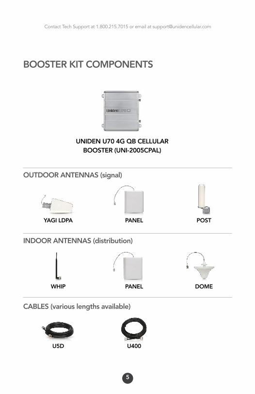
BOOSTER KIT COMPONENTS
UNIDEN U70 4G QB CELLULAR BOOSTER (UNI-2005CPAL)
WHIP
YAGI LDPA
PANEL
U400
PANEL
DOME
POST
U5D
OUTDOOR ANTENNAS (signal)
INDOOR ANTENNAS (distribution)
CABLES (various lengths available)

Contact Tech Support at 1.800.215.7015 or email at [email protected]
ANTENNA KITTING OPTIONS
UNI-601 OutdoorYagiAntenna(UNI-366)&30’U5DCoaxialCable(UNI-103)UNI-602 OutdoorYagiAntenna(UNI-366)&50’U5DCoaxialCable(UNI-104)UNI-603 OutdoorYagiAntenna(UNI-366)&75’U5DCoaxialCable(UNI-123)UNI-604 OutdoorYagiAntenna(UNI-366)&100’U5DCoaxialCable(UNI-105)UNI-605 OutdoorYagiAntenna(UNI-366)&30’U400CoaxialCable(UNI-111)UNI-606 OutdoorYagiAntenna(UNI-366)&50’U400CoaxialCable(UNI-112)UNI-607 OutdoorYagiAntenna(UNI-366)&75’U400CoaxialCable(UNI-121)UNI-608 OutdoorYagiAntenna(UNI-366)&100’U400CoaxialCable(UNI-113)UNI-609 OutdoorYagiHighGainAntenna(UNI-367)&30’U5DCoaxialCable(UNI-103)UNI-610 OutdoorYagiHighGainAntenna(UNI-367)&50’U5DCoaxialCable(UNI-104)UNI-611 OutdoorYagiHighGainAntenna(UNI-367)&75’U5DCoaxialCable(UNI-123)UNI-612 OutdoorYagiHighGainAntenna(UNI-367)&100’U5DCoaxialCable(UNI-105)UNI-613 OutdoorYagiHighGainAntenna(UNI-367)&30’U400CoaxialCable(UNI-111)UNI-614 OutdoorYagiHighGainAntenna(UNI-367)&50’U400CoaxialCable(UNI-112)UNI-615 OutdoorYagiHighGainAntenna(UNI-367)&75’U400CoaxialCable(UNI-121)UNI-616 OutdoorYagiHighGainAntenna(UNI-367)&100’U400CoaxialCable(UNI-113)UNI-617 OutdoorPanelAntenna(UNI-363)&30’U5DCoaxialCable(UNI-103)UNI-618 OutdoorPanelAntenna(UNI-363)&50’U5DCoaxialCable(UNI-104)UNI-619 OutdoorPanelAntenna(UNI-363)&75’U5DCoaxialCable(UNI-123)UNI-620 OutdoorPanelAntenna(UNI-363)&100’U5DCoaxialCable(UNI-105)UNI-621 OutdoorPanelAntenna(UNI-363)&30’U400CoaxialCable(UNI-111)UNI-622 OutdoorPanelAntenna(UNI-363)&50’U400CoaxialCable(UNI-112)UNI-623 OutdoorPanelAntenna(UNI-363)&75’U400CoaxialCable(UNI-121)UNI-624 OutdoorPanelAntenna(UNI-363)&100’U400CoaxialCable(UNI-113)UNI-625 OutdoorPostAntenna(UNI-362)&30’U5DCoaxialCable(UNI-103)UNI-626 OutdoorPostAntenna(UNI-362)&50’U5DCoaxialCable(UNI-104)UNI-627 OutdoorPostAntenna(UNI-362)&75’U5DCoaxialCable(UNI-123)UNI-628 OutdoorPostAntenna(UNI-362)&100’U5DCoaxialCable(UNI-105)UNI-629 OutdoorPostAntenna(UNI-362)&30’U400CoaxialCable(UNI-111)UNI-630 OutdoorPostAntenna(UNI-362)&50’U400CoaxialCable(UNI-112)UNI-631 OutdoorPostAntenna(UNI-362)&75’U400CoaxialCable(UNI-121)UNI-632 OutdoorPostAntenna(UNI-362)&100’U400CoaxialCable(UNI-113)UNI-633 OutdoorPostAntenna(UNI-362)&100’U400CoaxialCable(UNI-113)UNI-634 OutdoorPostAntenna(UNI-362)&100’U400CoaxialCable(UNI-113)
Outdoor Antenna & Cable Kit Options
6

Contact Tech Support at 1.800.215.7015 or email at [email protected]
UNI-373 IndoorWhipOmniDirectionalAntenna(UNI-373)UNI-651 IndoorPanelAntenna(UNI-374)&3’U5DCoaxialCable(UNI-119)UNI-652 IndoorPanelAntenna(UNI-374)&15’U5DCoaxialCable(UNI-118)UNI-653 IndoorPanelAntenna(UNI-374)&30’U5DCoaxialCable(UNI-103)UNI-654 IndoorPanelAntenna(UNI-374)&50’U5DCoaxialCable(UNI-104)UNI-655 IndoorPanelAntenna(UNI-374)&75’U5DCoaxialCable(UNI-123)UNI-656 IndoorPanelAntenna(UNI-374)&100’U5DCoaxialCable(UNI-105)UNI-657 IndoorPanelAntenna(UNI-374)&30’U400CoaxialCable(UNI-111)UNI-658 IndoorPanelAntenna(UNI-374)&50’U400CoaxialCable(UNI-112)UNI-659 IndoorPanelAntenna(UNI-374)&75’U400CoaxialCable(UNI-121)UNI-660 IndoorPanelAntenna(UNI-374)&100’U400CoaxialCable(UNI-113)UNI-661 IndoorDomeAntenna(UNI-372)&3’U5DCoaxialCable(UNI-119)UNI-662 IndoorDomeAntenna(UNI-372)&15’U5DCoaxialCable(UNI-118)UNI-663 IndoorDomeAntenna(UNI-372)&30’U5DCoaxialCable(UNI-103)UNI-664 IndoorDomeAntenna(UNI-372)&50’U5DCoaxialCable(UNI-104)UNI-665 IndoorDomeAntenna(UNI-372)&75’U5DCoaxialCable(UNI-123)UNI-666 IndoorDomeAntenna(UNI-372)&100’U5DCoaxialCable(UNI-105)UNI-667 IndoorDomeAntenna(UNI-372)&30’U400CoaxialCable(UNI-111)UNI-668 IndoorDomeAntenna(UNI-372)&50’U400CoaxialCable(UNI-112)UNI-669 IndoorDomeAntenna(UNI-372)&75’U400CoaxialCable(UNI-121)UNI-670 IndoorDomeAntenna(UNI-372)&100’U400CoaxialCable(UNI-113)
Indoor Antenna & Cable Kit Options
7

Contact Tech Support at 1.800.215.7015 or email at [email protected]
8
QUICK INSTALL OVERVIEW1. Uniden Booster - Select LocationInstalltheUnidenBoosterinanareathatisprotectedfromtheweather,properlyventilatedandisawayfromexcessiveheatandmoisture.
2. Donor (Outdoor) Antenna - Select LocationTheideallocationfortheoutdoorantennaisontheroofofthebuildingoramaststructure.Theantennashouldbeplacedinamannerthatallowsittocapturethebestpossiblecellularsignal.
3. Outdoor Coaxial Cable - Select LocationConnecttheoutdoorcoaxialcabletotheconnectiononthebackoftheoutdoorantennaandrunthecabletotheUnidenBoosterandattachittotheconnectorlabelled“outdoor”ontheUnidenBooster.
4. Indoor Coaxial Cable - (if used)Connecttheindoorcoaxialcabletotheconnectorlabelled“indoor”ontheUnidenBooster.Runthecabletothelocationofyourindoorantennaandattachittotheconnectoronthebackoftheindoorantenna.
5. Indoor AntennaTheideallocationfortheindoorantennawillbetheareaofyourpropertywhereyouneedtoimprovethesignalmost. Note: Thesignalstrengthwillbestrongestclosesttotheantenna.Whip Antenna-connectthewhipantennadirectlytotheUnidenBoostertotheconnectorlabelled“indoor”.Panel or Dome Antenna-mounttowallorceilinginyourselectedlocationandattachtocoaxialcablethatisconnectedtotheUnidenBooster.
6. Lightning Surge Protector - (sold separately)ThelightningsurgeprotectorconnectsinbetweentheoutdoorantennaandtheUnidenBooster.Thelightningsurgeprotectorcanbeinstalledindoorsoroutdoors.Whenconnectingoutdoors,installthelightningsurgeprotectorinlinebetweentheoutdoorantennaandtheoutdoorcoaxialcable.Whenconnectingindoors,installthelightningsurgeprotectorinlinebetweentheoutdoorcoaxialcableandtheUnidenBooster.
7. Commissioning The SystemA.BeforepoweringuptheUnidenBooster,besurethatallconnectionsaretightandconfirmthepoweradapterisconnectedtotheAC110voltline.B.PowerontheUnidenBoosterbyconnectingthepoweradaptertothedevice.C.CheckthestatusofthealarmLEDlightsandbesuretheyareallgreen.ThegaincontroldipswitchesontheUnidenBoosteraresetintheoffpositionwhenshipped,pleaserefertotheinstructionmanualformoredetailedinstructionstoattenuateyourUnidenBooster.
Contact Tech Support at 1.800.215.7015 or email at [email protected]
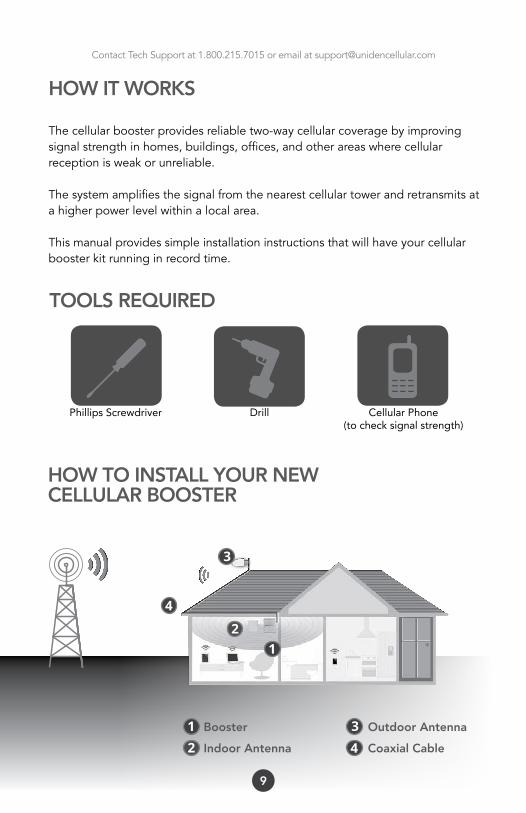
Phillips Screwdriver Drill Cellular Phone (to check signal strength)
TOOLS REQUIRED
9
HOW IT WORKS
Thecellularboosterprovidesreliabletwo-waycellularcoveragebyimprovingsignalstrengthinhomes,buildings,offices,andotherareaswherecellularreceptionisweakorunreliable.
Thesystemamplifiesthesignalfromthenearestcellulartowerandretransmitsatahigherpowerlevelwithinalocalarea.
Thismanualprovidessimpleinstallationinstructionsthatwillhaveyourcellularboosterkitrunninginrecordtime.
HOW TO INSTALL YOUR NEWCELLULAR BOOSTER
1
1
2
2
4
4
3
3Booster
Indoor Antenna
Outdoor Antenna
Coaxial Cable
Contact Tech Support at 1.800.215.7015 or email at [email protected]
10
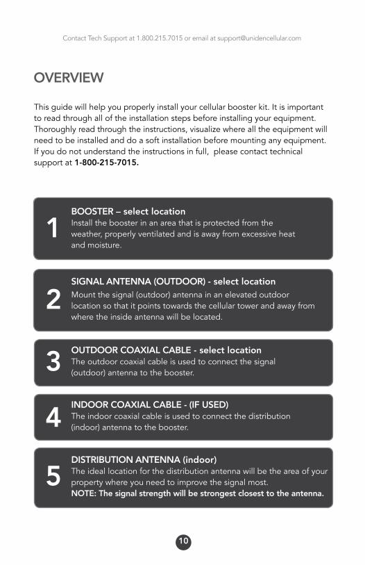
Thisguidewillhelpyouproperlyinstallyourcellularboosterkit.Itisimportanttoreadthroughalloftheinstallationstepsbeforeinstallingyourequipment.Thoroughlyreadthroughtheinstructions,visualizewherealltheequipmentwillneedtobeinstalledanddoasoftinstallationbeforemountinganyequipment.Ifyoudonotunderstandtheinstructionsinfull,pleasecontacttechnicalsupportat 1-800-215-7015.
OVERVIEW
BOOSTER – select locationInstalltheboosterinanareathatisprotectedfromtheweather,properlyventilatedandisawayfromexcessiveheatandmoisture.
1
SIGNAL ANTENNA (OUTDOOR) - select locationMountthesignal(outdoor)antennainanelevatedoutdoorlocationsothatitpointstowardsthecellulartowerandawayfromwheretheinsideantennawillbelocated.
2
OUTDOOR COAXIAL CABLE - select locationTheoutdoorcoaxialcableisusedtoconnectthesignal(outdoor)antennatothebooster.3INDOOR COAXIAL CABLE - (IF USED)Theindoorcoaxialcableisusedtoconnectthedistribution(indoor)antennatothebooster.4DISTRIBUTION ANTENNA (indoor)Theideallocationforthedistributionantennawillbetheareaofyourpropertywhereyouneedtoimprovethesignalmost.NOTE: The signal strength will be strongest closest to the antenna.
5

Contact Tech Support at 1.800.215.7015 or email at [email protected]
11
LIGHTNING SURGE PROTECTOR - (SOLD SEPARATELY)Thelightningsurgeprotectorconnectsinbetweenthesignalantennaandthebooster.IMPORTANT: Lightning surge protector must be grounded.
6
7 COMMISSIONING THE SYSTEM
SignalAntenna (outdoor)
SurgeProtector
Booster
DistributionAntenna(indoor)
Splitter(ifusingmutlipleantenna)
DistributionAntennas(optionalantennasforadditionalcoverage)
12
43
12
4 6 7
3 5
5
6 7&

Contact Tech Support at 1.800.215.7015 or email at [email protected]
12
Plan the layout of your system
Beforeyougetstartedyouwillneedtoplanthelayoutofyoursystem.Thisinvolvescheckingsignalstrengthforsignalscomingfromthecellulartower,aswellasantenna,boosterandcableplacement.
IDENTIFY THE BEST LOCATION TO INSTALL THE SIGNAL (OUTDOOR) ANTENNA.
Check for signal strength
Select a location on theroofofthebuildingtoinstallthesignalantenna,bymonitoringyourcellularphone’ssignalstrength(signalbars)tofindthestrongestsignalfromyourcarrier’scellulartower.
Mark the area
Markthatareaastheinstallationlocationforthesignal(outdoor)
GETTING STARTED

Contact Tech Support at 1.800.215.7015 or email at [email protected]
13
RUN COAXIAL CABLE
Looselyrunthecoaxialcablefromyouroutdoorantennatoyourbooster.(afteryouhavetestedthesystemyoucanpermanentlysecurethecoaxialcable).
As you route and pull cabling, follow these general guidelines:
• Bendcablesandroutethemsmoothly,andprotecttheouterskinagainstanydamage.
• Keephorizontalcablesstraightandfastenthemwithatieeverythreetofivefeet.
• Bindandfastenverticalcableseverysixtoeightfeet.
• Waterproofalloutdoorconnectionswithsiliconecaulking
• Becarefulwhenpluggingtheconnectorinsoasnottodamagethecenterpinsontheconnectors.
INSTALL THE SIGNAL (OUTDOOR) ANTENNA
Mount the signal (outdoor) antenna:
Thesignalantennashouldbelocatedashighaspossibleinordertocapturethebestqualitysignalfromthecellulartower.
Wheninstallingadirectionalantenna,inordertoavoidlargetreesorobstacles,youmayneedtoslightlytilttheantennaupwardstocaptureausablesignal.
Usethemountinghardwareinthekittoattachthesignal(outdoor)antennatothebuilding.
Connect the signal (outdoor) antenna:
Connectthesuppliedcoaxialcabletotheantenna.Werecommendapplyingsiliconecaulkingtofullywaterprooftheconnection.
Attachthecableinsuchawaythatadriploopisformed.(seeimagenextpage).Oncemounted,connectoneendofthecoaxialcabletothesignal(outdoor)antennaandtheotherendtothecellularboosterwhereitismarked“outdoor”.

Contact Tech Support at 1.800.215.7015 or email at [email protected]
14
DripLoop
CAUTION: pleaseensureneitheryounortheantennacomeincontactwithelectricalpowerlines.
UNDERSTAND THE DIFFERENT SIGNAL (OUTDOOR) ANTENNA
Signal(outdoor)antennas,areneededtocapturethesignalemanatingfromyourcarrier’scellulartower.Therearedifferenttypesofsignal(outdoor)antennaseachdesignedtomeetyourspecificneeds.Theyagilpdaantenna,thepostantenna&thepanelantenna.

Contact Tech Support at 1.800.215.7015 or email at [email protected]
15
The Yagi Lpda AntennaTheyagiisaveryprecisedirectionalantennawithapowerfulreach.Thisantennashouldbeinstalledinanelevatedpositionandmustbepointedtowardsyourcarrier’scellulartower.Note: This antenna is not meant to capture signal from multiple carriers.
The Post AntennaThepostisanomni-directionalantennawitha360degreereach.Thisantennashouldbeinstalledinanelevatedposition.Itisdesignedtocapturethesignalfrommultiplecarriertowers.
The Panel AntennaThepanelisadirectionalantennawitha120degreereachandisdesignedtocapturethesignalfrommultiplecarriertowers.Thisantennashouldbeinstalledinanelevatedpositionandmustbepointedtowardsyourcarrier’scellulartowers.

ContactTechSupport7daysaweekat1.800.215.7015oremailatsupport@unidencellularbooster.com
16
Thelightningsurgeprotectorcanbeinstalledindoorsoroutdoors.Whenconnectingoutdoors,installthelightningsurgeprotectorinlinebetweenthesignal antenna (outdoor)andthecoaxialcable.Whenconnectingindoors,installthelightningsurgeprotectorinlinebetweentheoutdoorcoaxialcableandthebooster.
INSTALL THE DISTRIBUTION (INDOOR) ANTENNA
Selecttheinstallationlocationofyoursupplieddistribution(indoor)antennabasedonthefollowing:
Dome omni directional antennaPlaceinthecenteroftheareawherethesignalneedstobeamplified.
Panel directional antennaPlaceintheouterperimeteroftheareathesignalneedstobeamplified.
Whip omni directional antenna Mountdirectlytotheconnectormarked“indoor”onthecellularbooster.
LIGHTNING SURGE PROTECTOR(sold separately)
IMPORTANT: Lightningsurgeprotectormustbegrounded.Connectagroundwiretotheappropriateplaceonthelightningsurgeprotectorandconnecttheotherendtoaverifiedgroundsource.
!

ContactTechSupport7daysaweekat1.800.215.7015oremailatsupport@unidencellularbooster.com
17
CONNECTING THE DISTRIBUTION (INDOOR) ANTENNA
Dome omni directional antenna Connectoneendofthecoaxialcabletothedomeantennaandtheotherendtothecellularboosterwhereitismarked“indoor”.
Panel directional antenna Connectoneendofthecoaxialcabletothepanelantennaandtheotherendtotheconnectoronthecellularboosterwhereitismarked“indoor”.
Whip omni directional antenna Connecttheantenna’senddirectlytotheconnectoronthecellularboosterwhereitismarked“indoor”.
NOTE: In some cases multiple distribution antennas will be required for com-plete coverage in large buildings and multiple levels.
Contact Tech Support at 1.800.215.7015 or email at [email protected]
18
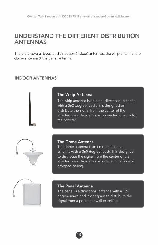
UNDERSTAND THE DIFFERENT DISTRIBUTION ANTENNAS
Thereareseveraltypesofdistribution(indoor)antennas:thewhipantenna,thedomeantenna&thepanelantenna.
INDOOR ANTENNAS
The Whip Antenna
Thewhipantennaisanomni-directionalantenna witha360degreereach.Itisdesignedtodistributethesignalfromthecenteroftheaffectedarea.Typicallyitisconnecteddirectlytothe booster.
The Dome AntennaThedomeantennaisanomni-directionalantennawitha360degreereach.Itisdesignedtodistributethesignalfromthecenteroftheaffectedarea.Typicallyitisinstalledinafalseordroppedceiling.
The Panel AntennaThepanelisadirectionalantennawitha120degreereachandisdesignedtodistributethesignalfromaperimeterwallorceiling.
Contact Tech Support at 1.800.215.7015 or email at [email protected]
19
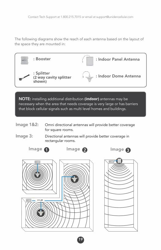
Thefollowingdiagramsshowthereachofeachantennabasedonthelayoutofthespacetheyaremountedin:
Image1Image 32
: Indoor Panel Antenna
: Indoor Dome Antenna
: Booster
: Splitter(2 way cavity splitter shown)
Image
Image 1&2: Omnidirectionalantennaswillprovidebettercoverage forsquarerooms.
Image 3: Directionalantennaswillprovidebettercoveragein rectangularrooms.
NOTE: installingadditionaldistribution(indoor) antennas may be necessarywhentheareathatneedscoverageisverylargeorhasbarriersthatblockcellularsignalssuchasmultilevelhomesandbuildings.

Contact Tech Support at 1.800.215.7015 or email at [email protected]
20
IMPORTANT: Donotconnectyourcellulardevicetothecellularbooster,asitmaydamageyourcellulardevice.
ANTENNA SEPARATION
!
PointYagiAntennaawayfromIndoor
Antenna
Indoorantenna

Contact Tech Support at 1.800.215.7015 or email at [email protected]
21
INSTALL YOUR CELLULAR BOOSTER
Installthecellularboosterinalocationthatisproperlyventilatedandnotexposedtoexcessiveheat,moistureand/ordirectsunlight.Theoptimalareawouldbeonawalllocatednearapoweroutlet.
Itshouldbemountedinaneasilyaccessibleareasoit’seasytoperformgeneralmaintenancewiththecoaxialcableconnections,dipswitchsettingsandpoweradaptor.
Makesureallcablesandantennasaresecurelyconnectedbeforecommissioningthe system.
POWER UP YOUR CELLULAR BOOSTER
Onceallthenextpageprecautionshavebeentaken,poweronthecellularbooster.

Contact Tech Support at 1.800.215.7015 or email at [email protected]
22
IMPORTANT:
1 Neverpointthefrontoftheyagisignal (outdoor) antennatowardstheinsideofthedistribution(indoor) antenna.
2 Verifythatthesuppliedcoaxialcablesfromboththesignal (outdoor)antennaandthedistribution(indoor) antennaareproperlyconnectedtothecellularboosterbeforepoweringitup.
3 Carefullypluginthesupplied110-voltpoweradaptorintothebackofthecellularboosterwhereitismarked‘power’andconnecttheotherendtoapoweroutlet.
WARNING! Usingapowersupplythatisnotincludedinyourkitcoulddamageyourequipmentandvoidyourwarranty.
CHECK THE CELLULAR BOOSTER LEDALARM LIGHTS
Yourcellularboostercomesequippedwithelectronicsensorsdesignedtoidentifycellularsignaloverloadoroscillationwhichcanhindersignal-boostingperformance.Yourcellularboosterisspeciallydesignedtoautomaticallydecreasegaintocompensateforthesecircumstances.Thedevicealsohasafeaturetoautomaticallyshutdownincaseofexcessiveoscillation.
Improperequipmentinstallationandunusablesignalqualitycancauseoscillation,thisiswhyitisimportanttofullyunderstandtheLEDalarmlightsonyourbooster,astheywillhelpyouidentifyandsolveanypotentialissues.
ThecoloroftheLEDindicatesthestatusoftheboostersystem.
!

Contact Tech Support at 1.800.215.7015 or email at [email protected]
LED INDICATORS
ThecoloroftheLEDindicatesthestatusoftheboosterforeachofthesefrequencies.ThereisonealarmLEDlightforeachofthecellularfrequencyranges.
CHECKING THE SIGNAL STATUS
Thesignalindicator’sLEDwillnotifyyouastowhetheryourcellularbooster is experiencinganyoscillationorfeedback.ThepurposeoftheseLED’sistoallowyoutofinetuneyourboostertoachieveoptimalsignalquality.
Thebulletlistbelowindicateswhatmeasureshouldbetakenbasedonthe color oftheLEDalarmlights.
Green: indicatesthesystemisworkingproperly.
Orange: thesystemisexperiencingslightoscillationandrequiresslightadjustment.Seenextpageforadjustmentprocedures.
Red: thesystemisexperiencingsevereoscillation.Turntheunitoffandmakeadjustmentsasoutlinedonthenextpage.
OFF: iftheLEDisoffitislikelythesystemwentintooscillationsoseverethattheautogainandlevelcontrolcircuitsturnedthecellularboosteroff.
23

Contact Tech Support at 1.800.215.7015 or email at [email protected]
24
ADJUSTING THE MANUAL GAIN CONTROL
TheUnidenU704GQB(UNI-2005CPAL)allowyoutomanuallyattenuatethedbgainofthedeviceinincrementsof1dbwithamaximumof31db.
Themanualgaincontrol(MGC)adjuststheoverallamplificationlevel(gain)ofthebooster.TheManualGainControlisusedtoresolvetheissueofoscillationwithouttheneedofreadjustingyourantennas,inmostcases.
TheMGCallowsyoutoeasilyreducetheamountofgain(amplification)theboosterisemitting.Thisisdonewithasetofdipswitchestoattenuatethegainonthesideofthebooster.
Therearefoursetsofdipswitches,whenputintothe“ON”positionwillreducethegainoftheboosterforthedesignatedfrequency.WhentheLEDalarmsindicateoscillation(turnsorange,redoroff)youneedtoreducethegainofboosterfortheappropriatefrequency.Dothisgraduallyinordertodeterminetheideallevel.
TheUnidenU704GQB(UNI-2005CPAL)canbehavethegainreducedby31db.Whenadipswitchismoveduptothe“ON”positionitwillimplementareductionfortheamountofgainindicated.Therefore,toimplementa5dbreduction,pushthedipswitchmarked4&1up.Toimplementa10dbreductionpushthedipswitchmarked8&2up.

Contact Tech Support at 1.800.215.7015 or email at [email protected]
HERE IS A BREAKDOWN OF THE DIP SWITCH SECTIONS
The first section is labeled ‘AWS’ Thefirstsetofdipswitchescontroltheattenuationofthe1700/2100MHzfrequencyrange.
The second section is labeled ‘PCS’Thefirsttwodipswitchescontroltheattenuationofthe1900MHzfrequencyrange.
The third section is labeled ‘CDMA’Thefirsttwodipswitchescontroltheattenuationofthe850MHzfrequencyrange.
The fourth section is labeled ‘L’TE Thefirsttwodipswitchescontroltheattenuationofthetwo700MHzfrequencyranges.
Eachsetofdipswitchesgivesyoutheabilitytoreducetheamplificationby31dbin1dbincrements.Thefirstdipswitchrepresentsa1dbreduction.theseconda2dbreduction,thethirda4dbreduction,thefourthan8dbreductionandthefiftha16dbreduction.
25
Uniden U70 4G QB (UNI-2005-QB-CPAL) MGC dip switches
Contact Tech Support at 1.800.215.7015 or email at [email protected]
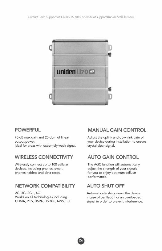
70dBmaxgainand20dbmoflinearoutputpower.Idealforareaswithextremelyweaksignal.
Wirelesslyconnectupto100cellulardevices,includingphones,smartphones,tabletsanddatacards.
TheAGCfunctionwillautomaticallyadjustthestrengthofyoursignalsforyoutoenjoyoptimumcellularperformance.
Adjusttheuplinkanddownlinkgainofyourdeviceduringinstallationtoensurecrystal clear signal.
Automaticallyshutsdownthedeviceincaseofoscillationoranoverloadedsignalinordertopreventinterference.
AUTO GAIN CONTROL
MANUAL GAIN CONTROLPOWERFUL
WIRELESS CONNECTIVITY
AUTO SHUT OFFNETWORK COMPATIBILITY2G,3G,3G+,4GWorksonalltechnologiesincludingCDMA,PCS,HSPA,HSPA+,AWS,LTE.
26

Contact Tech Support at 1.800.215.7015 or email at [email protected]
27
BOOSTER TECHNICAL SPECIFICATIONS
MGC(StepAttenuation)
AutomaticLevelControl
AutomaticGainControl
Inter-modulation
SpuriousEmission
LED Alarm
PowerLED
ALCLED
Mechanical Specifications
I/OPort
Impedance
OperatingTemperature
EnvironmentConditions
Dimensions
Weight
PowerSupply
DownlinkUplink
51dB
9KHz~12.75GHz ≤-13dBm ≤-13dBm
9KHz~12.75GHz ≤-13dBm ≤-13dBm
PowerIndicator
Orange@ALC1~5dB,Red@ALC15dBLEDoffafter5secondsredcolor.
N-Female
50ohm
-10ºC~+80ºC
IP40
218*165*50mm
≤2.5Kg
InputAC90~264V,OutputDC12V/3A
Standard
Standard
LTE(A+B)LTEC CDMAPCSAWS
LTE(A+B)LTEC CDMAPCSAWS
Electrical Specifications
704~716MHz776~787MHz 824~849MHz1850~1910MHz1710~1755MHz
734~746MHz746~757MHz 869~894MHz1930~1990MHz2110~2155MHz
12MHz10MHz25MHz60MHz45MHz
Frequencyrange
Bandwidth
Max.Gain
Max.OutputPower
≥65dB ≥70dB
≥17dBm 20~25dBm
≥15dB,autoshutoffafter15dB
31dB/1dBstep

Contact Tech Support at 1.800.215.7015 or email at [email protected]
NOTES AND WARNINGS
Warning:Neverpointthedirectionalantennatowardstheinsidedistributionantenna,thiswillcauseoscillationandtheboosterwillshutdown.
Note: Oscillation(feedback)canoccurwhentheoutside(signal)antennaistooclosetotheinside(distribution)antenna.OscillationinasignalboosterissimilartowhenamicrophoneistooclosetoaspeakerinPAsystemwhichcausealoudscreechingsound.Whenthisoscillationhappens,itcanpotentiallyinterferewithnearbycellulartowers.
Warning:Neverconnectthesignalboosterdirectlytoyourcellulardeviceasthismaydamageyourcellulardevice.
Warning:Anyantennausedwiththisdevicemustbeatleast8inchesfromanyperson.
Warning:Ensurethatbothantenna’sareconnectedtothesignalboosterbeforecommissioning the system.
Note:ThisdevicecomplieswithPart15ofFCCrules.Operationissubjecttotwoconditions:1.Thisdevicemaynotcauseharmfulinterference,and2.thisdevicemustacceptanyinterferencereceived,includinginterferencethatmaycauseundesiredoperation.ChangedormodificationnotexpresslyapprovedbySignifiMobileInccouldvoidtheauthoritytooperatethisequipment.
28

Contact Tech Support at 1.800.215.7015 or email at [email protected]
Important Note:Beforeuse,youmustregisterthisconsumerdevicewithyourwirelessproviderandhavetheirconsent.Themajorityofwirelessprovidershaveconsentedtotheuseofsignalboosters.Youmustoperatethisdevicewithapprovedantennasandcablesasspecifiedintheinstallguide.IfrequestedbytheFCCoracellularserviceprovider,thedevicewillneedtobeturnedoffimmediately.Warning:E911locationinformationmaybeinaccurateforcallsplacedwhileusingthisdevice.
FCC RF Exposure StatementThisequipmentcomplieswithFCCradiationexposurelimitssetforthforanuncontrolledenvironment.EndusersmustfollowthespecificoperatinginstructionforsatisfyingRFexposurecompliance.Thistransmittermustnotbeco-locatedoroperatinginconjunctionwithanyotherantennaortransmitter.
Important Note Related to Industry CanadaRadioequipmentthatisinstalled,activated,modified,repaired,maintainedorallowedtobeoperatedisdulyauthorizedandoperatedinaccordancewiththeaforementionedauthorization,bycheckingtheoperator’slicense,or,failingthat,consultingthefollowingwebsiteat:http://spectrumdirect.ic.gc.ca
29

Contact Tech Support at 1.800.215.7015 or email at [email protected]
30
TROUBLESHOOTINGTheLEDalarmlightsrepresentthestatusoftheboosteroneachfrequency.Whenthelightsaregreenthedeviceisoperatingnormallymeaningthatitisnotexperiencinganyoscillation(feedback)anditisboostingthesignalatmaximumpower.WhentheLEDlightsbegintochangecolorfromgreentoorangetored,itmeansthatparticularfrequencyisexperiencingsomeoscillation(feedback).
Iftheoscillationisexcessivetheboosterwillshutdownforthatparticularfrequency.Theboosterwillstillworkfortheotherfrequencyonamulti-bandbooster.
Oscillationiscausedwhentheindoor(distribution)antennasendsasignalbackintotheoutdoor(signal)antenna.SimilartoaPAsystem,whenthemicrophonegetstooclosetothespeakeritcausesfeedback.Thiswilloccurifyourantennasaretooclosetogether,ortheindoorantennaispointedattheoutdoorantenna.Makesureyouhaveadequateseparationandsometypeofshieldingbetweentheantennas(usuallyyourrooforacementwallisgoodenough).
IMPORTANT NOTESThe2mostimportantthingstolookforwhensettingupyoursystemis:
Agoodinputsignal(the best you can find)1Isolatingtheoutdoor(signal) antennafromtheindoor (distribution)antennassotheydonotfeedbackintoeachother.2
Contact Tech Support at 1.800.215.7015 or email at [email protected]
31
Bycapturingthebestinputsignalyouwillbeabletoenjoythemaximumcoverageandbestqualitysignalinsidewhereyourdistributionantennasarelocated.Thebettertheinputsignal,thebettertheoutputsignal.Inordertofindthebestinputsignal,youwanttoplaceyouroutdoor(signal)antennaashighaspossiblewiththeleastamountofobstructionbetweentheantennaandthecellularbasetower.Aclearlineofsiteisideal. Isolatingthesignalfromtheantennasisdonebyensuringthattheantennasarenotpointingtoeachotherandbyhavingenoughdistanceorbarriershieldinginbetweenthem.Thesignalstravellikeraysofsunlight,adirectionalantennawillsendthesignalinthedirectionthatitispointing.Anomnidirectionalantennawillsendthesignalineverydirectionaroundit.Sodependingonyourequipmentitsimportanttobesurethatyourdistributionantenna(indoor)isnotsendingthesignalbackintotheoutdoor(signal)antenna.
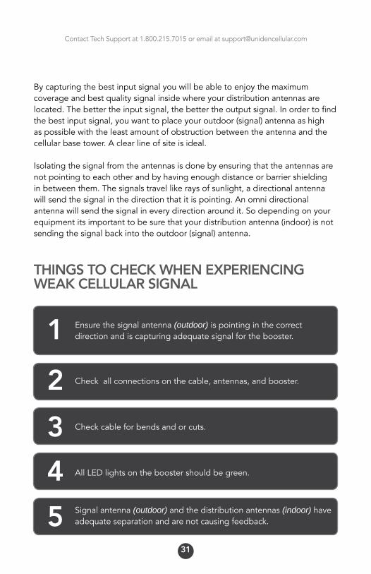
THINGS TO CHECK WHEN EXPERIENCING WEAK CELLULAR SIGNAL
Checkallconnectionsonthecable,antennas,andbooster.2Checkcableforbendsandorcuts.3AllLEDlightsontheboostershouldbegreen.4
Ensurethesignal antenna (outdoor)ispointinginthecorrectdirectionandiscapturingadequatesignalforthebooster.1
Signal antenna (outdoor)andthedistributionantennas(indoor)haveadequateseparationandarenotcausingfeedback.5
Contact Tech Support at 1.800.215.7015 or email at [email protected]
32
FREQUENTLY ASKED QUESTIONS
WHY ARE THE LED LIGHTS TURNING ORANGE, RED OR SHUTTING OFF?
Therearecertaincaseswhereyoursystemcouldbeexperiencingoscillation.Thiscanbeattributedtoeitherthequalityofyourinputsignalorhavingyoursignal(outdoor)antennaanddistribution(indoor)antennatooclosetogether.Pleasereviewthefollowingguidelinestohelpresolvethisissue:
1. Adjustthedirectionofthesignal(outdoor)antenna.Ifthesystemisreceivingaveryhighinputsignal,youcanpointyoursignal(outdoor)antennaawayfromthecellulartowertoreducethestrengthoftheinputsignalandtherefore,reducetheoscillation.Alternativelyifyoursystemisreceivingaverypoorqualitysignal(weakandunusablesignal),youcanpointyoursignal(outdoor)antennamoredirectlytowardsthecellulartowertoincreasethestrengthoftheinputsignal.Sometimesthismayrequirecompletelyrepositioningtheantennatoalocationwhereyoucanachievealine of site to the tower.
2. Increasetheseparationbetweenthesignal(outdoor)antennaandthedistribution(indoor)antenna.Thiscanbeachievedbyincreasingthedistancebetweenthetwoantennasorbyplacingbarriersbetweenthem,suchasmovingthedistribution(indoor)antennatoanadjacentroomwheretherewouldbeanadditionalwallseparatingthemfromthesignal(outdoor)antenna.
3. ManualGainControl.Adjustthegainwiththemanualgaincontrolfunctionusingthedipswitchesonthesideofthebooster.
See page 22 for more details.
Contact Tech Support at 1.800.215.7015 or email at [email protected]
33
I INSTALLED THE BOOSTER AND MY SIGNAL STRENGTH IS STILL WEAK
Inordertocorrectaweaksignal;essentiallyyouhavetheoptionsof:
• Adjusttheaimofthesignal(outdoor)antennaorreplaceitwitha higher gain antenna.
• Movethedistribution(indoor)antenna.• Increasethenumberofdistribution(indoor)antennas.• Reducingtheattenuationvaluesyouchosewhensettingthemanualgain
control.
I CANNOT MAINTAIN CALLS, MY SIGNAL STRENGTH FLUCTUATES
Ifyoufindtheboosterisworkingbutdropscallsordeliversfluctuatingsignallevels,themostlikelycauseisoscillationbetweenthesignalanddistributionantenna(s).
Determinethestatusofthecellularboosterledalarms.Ifsothereisinsufficientisolationbetweenantennas.Youcaneitherincreasethedistancebetweenantennasorplacebarriersbetweenthemtoattenuatethesignalsoradjustthemanualgaincontrolsettings.
Asecondcauseforthissymptomispoorcableconnections.Confirmthatallcableconnectionsaretightandsecure.
Athirdcausemaybeinterferencefromothercellularserviceprovidersoperatinginthesamefrequencybands.Iftheirsignalsarestrongerthanthecellularsignalsyouwanttoreceivefromthecelltower.Inthiscasetheunwantedsignalneedstobeattenuatedeitherbyrepositioningorre-aligningthesignal(outdoor)antenna,orbyusingbarriers(buildings,trees,etc)toblockthesignal.

Contact Tech Support at 1.800.215.7015 or email at [email protected]
34
MY LED’S ARE ALL GREEN BUT MY SIGNAL IS STILL WEAK - MY COVERAGE IS POOR
Ifyoureceiveasignalwhereyoudidnotpreviously...or,iftheradiusoftheserviceareacoveredissmall...andyourLED’sareallgreen...theboosterisworkingproperlybutforsomereasonthesignalisnotverystrong.Thiscanbeduetoweakinputsignal.
• Adjustyoursignal(outdoor)antennatopointmoreaccuratelyatthecellulartowerinordertoincreasetheinputsignal.
• Checkthecoaxialcabletoensuretherearenotanycreasesorcutsinit.Perhapsthecablewasdamagedduringinstallation.
WHY ISN’T MY CELL PHONE INDICATING MORE SIGNAL WITH MORE BARS?
Youmaynotalwaysobservemorebarsonyoursignalmeterbecauseofthesignalspreadingoutfromtheantenna.Ifyourphonehasadbmeter,3dbisasignificantincreaseof2times,6dbis4times,and10dbis10times.onafourbarphone,one“bar”equalsabout10db.
Theincreaseinsignalyouwillseedependsupon:
• Thelevelofsignalatthesignal(outdoor)antenna
• Thecareoftheantennaplacement(2feetawayfrommetal,adequateantennaseparation[30feetrecommended]).
• Thedistanceofyourphone/devicefromthedistribution(indoor)antenna(signalspreadsordiminishesrapidlywithdistance.)
Contact Tech Support at 1.800.215.7015 or email at [email protected]
35
NOTES
Model # :Serial # :Date Purchased : Purchased From :Notes:

INSTRUCTION MANUAL
Phone: 1-800-215-7015 Email: [email protected]
www.unidencellular.com
TheUnidentrademarkisownedbyUnidenAmericaCorporationanditsaffiliatesisusedunderlicensebySignifiMobile.