conditioning of tail water flow by draft tube design – a new approach
TRANSCRIPT

CONDITIONING OF TAIL WATER FLOW BY DRAFT TUBE DESIGN – A NEW APPROACH FOR LOW HEAD
HYDROPOWER
M. Metzler, P. F. Pelz
Abstract: The optimization of fluid systems, i.e. draft tubes in low head hydropower stations is up to now commonly carried out by CFD analysis or based on empiric data. The reasons for that is a lack of analytical optimization methods. The present paper provides a new analytic approach to optimization of draft tubes. Furthermore it names and corrects two common fallacies in hydropower literature. The optimized draft tube design satisfies the optimal operation condition for hydropower in an open channel-flow [1].
1 Optimal Operation for Low Head Hydropower
A common criterion for efficiency of low pressure hydro power plants is the hydraulic
efficiency of the facility
(1)
It is the ratio of shaft power to the hydraulic energy at a particular operating point and it is a measure for the dissipation within the hydraulic machine and connected parts
like draft tubes. The turbine head , i.e. the difference of total head at positions and and the volume flow rate are considered as given by the hydrologic conditions of the surface water course. Anyway, while operating low pressure power stations it can be observed, that the hydraulic machine’s operating
point itself has an influence on the head and volume flow rate . The operating point determines which fraction of the available power can be converted into shaft power . The coefficient of performance is defined as that ratio
(2)
Since the shaft power of the system is normalized by the available power , the first step is to define the available power. Figure 1 shows a schematic hydro power
plant. Velocities are denoted by , water levels by and ground levels by . The effective head is defined as ⁄ . The second author defines
the available power, as the shaft power of a hypothetic ideal machine (without tail water – in fact there is no better machine one can think of) [1]
(
) ⁄
⁄ ⁄ (3)

The coefficient of performance can be expressed as a function of volume flow rate per width unit and tail water level height . Those two parameters define the operating point of the installed hydraulic machine.
As a consequence of the first law of thermodynamics, the coefficient of performance is
(
) ⁄
(
) (4)
CHANNEL WIDTH
Figure 1: Schematic cross section of low head hydropower plant (Case II)
With dimensionless operating parameters and (see Figure 2 for the definitions),
is plotted in Figure 2.
Since equation (4) is exact, it clearly shows the difference between hydraulic
efficiency and coefficient of performance once more (see Betz [2], Pelz [1]). The first is a measure for dissipation, the later a measure for system efficiency. It has to be emphasized, that considering hydraulic efficiency only can be misleading and is indeed insufficient for optimization of low head hydro power plants.
The optimum of equation (4) is ⁄ . In other words: half of the available
power in an open channel-flow can be converted into shaft power at the optimal operation point (see Figure 2) provided
(
) ⁄
and
(5)

0 0.2 0.4 0.60
0.2
0.4
0.6
0.8
1
⁄
Figure 2: Coefficient of performance as function of operating point [1]
2 Terminology of Total Pressure
In hydro power literature there is a multitude of terms in the context of pressure. In
some cases they are contradictory. The terms for the present paper follow the
definitions of E. Becker [3] in his excellent and crystal clear monograph on fluid
mechanics. The total pressure is the sum of static pressure potential of the
specific gravitational field , with and dynamic pressure
(6)
Provided ⁄ ( = flow direction) the static pressure at is given by
Hence the piezometric pressure is constant across any cross sections
and is no function of the coordinate (see Figure 1). The same is
true for the total pressure and the total head defined by
(7)
(It is homogenous at any cross section with ⁄ ). The total head has the
dimension of energy per volume unit [1], [3]. denotes pressure head, which is
equivalent to the water level height in an open channel-flow.

3 State of the Art Draft Tube Theory – a Limited Approach
With technological progress in hydro power a trend from machines of large diameter
at low specific speed to machines of smaller diameter at high specific speed can be
observed. With the decreasing size of machines investment cost per installed power
decreased as well. Otto Cordier [4] showed, based on empirical data, the correlation
of specific speed and specific diameter of hydraulic machines. The correlation
between specific diameter and investment cost is considered by Pelz and Metzler [5].
Due to small diameters, the meridian speed of flow along the hydraulic machine
increased compared to ancient machines of low rotational speed and large diameter.
Hence, the fraction of dynamic pressure in the total pressure is high (see equation
(6)) at the rotor outlet. Experiments indicate that draft tubes with large diffusers
enhanced the shaft power significantly, for machines of high rotational speed.
The common explanation for this effect is an assumed recuperation of energy within
the draft tube, due to conversion of dynamic pressure into static pressure. Deniz [6],
as one of various authors writes:
“To achieve high hydraulic efficiency it is necessary to recuperate the major
part of the outlet energy. Velocity energy has to be converted in pressure
energy at highest possible efficiency.”
In hydro power literature, kinetic energy that leaves the power plant is considered as
lost. This loss is expressed by Deniz [6] and Raabe [7] as the ratio of kinetic energy
at the rotor outlet and the turbine head defined as the difference of total head
between head water and tail water [6].
(8)
Due to Deniz [6] this loss has to be minimized, while it is assumed that the numerator
of definition (8) is variable and the denominator is fixed. Furthermore Deniz claims,
that the pressure gain leads to a pressure drop at the rotor outlet. Without a doubt
this pressure drop has been measured and can be considered as proofed. Only the
explanation is not adequate and hence misleading for optimization tasks.
4 Extended Approach
Ruprecht [8] already noticed that the tail water condition has an influence on the draft
tubes outlet flow, but did consider the tail water height as fixed, so did Deniz [6] and Raabe [7].
In the following section it will be shown, why the a conversion of hydrodynamic pressure into hydrostatic pressure inside the draft tube does not lead to higher shaft power since the total pressure drop does not change. Surprisingly this fact is not taken into account in state of the art draft tube theory.

Unlike Deniz, Raabe and Ruprecht, within the later sections of this work, we widen the view and take the downstream flow of the draft tube into account. By doing so, we enlighten the limitations of classical approaches and furthermore open the view to the two major functions of draft tubes.
The first one is to reduce dissipation namely the Carnot shock loss and hence
increases the hydraulic efficiency of the system. This function is understood by
most hydraulic engineers.
The second function is less obvious and up to now not clearly addressed: the draft
tube determines the tail water Froude number and tail water level and hence, the
none dissipative losses which are considered mainly by the coefficient of
performance divided by the hydraulic efficiency ⁄ .
5 The Impossibility of Energy Recuperation by Pressure Conversion
The term energy recuperation, that is used in hydropower literature to describe the function of the diffuser ([6], [9]), is misleading, since the energy content of a flow cannot be changed by the conversion of hydrodynamic pressure into hydrostatic pressure. Neither the energy flux at the outlet of the hydro power plant within the tail water can be lowered by conversion of pressure.
(9)
Equation (9)=(1) is shaft power of the turbine, expressed by the energy equation. Independently of the amount of piezometric pressure and dynamic
pressure the sum of both, the total pressure (see equation (6)), is constant in a system without an energy source or sink, like it is the case in between rotor outlet and diffuser outlet, for a only at the moment assumed ideal diffusor (no separation,
no friction). The volume flow rate is constant for stationary operation of hydro power plants. Hence, converting hydrodynamic pressure into hydrostatic, i.e. piezometric pressure does not have any influence on the shaft power of the turbine
.
In hydropower literature plants are modeled analytically under use of Bernoulli’s equation, which leads to feasible results for hydropower with large head. In low head hydropower effects of the free surface must be considered. The model concept of Bernoulli’s equation misleads at this point: Bernoulli’s equation is valid along a streamline for frictionless flow. For reasons of simple description this streamline, in case of hydro power plants, usually starts at the surface of the head water and ends
at the surface of the tail water. Now the common fallacy is, that the tail water level
is considered as fixed, while the tail water velocity is considered to be adjustable
by the diffuser. The definition of ⁄ implicit has this as a
preliminary. This assumption leads to a violation of mass conservation, as it will be shown in the following section. For an adequate description of the flow, including free surface effects, the first law of thermodynamics, which is of superior generality, compared to Bernoulli’s equation has to be applied. Then both equations, (i) the energy equation and (ii) the mass conservation law have to be satisfied.

6 Consideration of Free Surface
To explain the function of the diffuser in an adequate manner, the effects of the free surface have to be included in the analytic considerations. Therefore both, the first law of thermodynamics and mass conservation have to be satisfied as mentioned above. The first law of thermodynamics for the scheme in Figure 1 reads (see [1])
(10)
All of dissipative losses in the whole device including screen, inlet, hydraulic machine
and the draft tube, are summarized in the head loss . The main difference to the Bernoulli’s equation is, that first law of thermodynamics (equation (10)) is not only valid along a streamline. It is a conservation equation for the whole fluid body between any cross section of an open channel.
For a stationary operating hydro power plant with volume flow rate and rectangular channel cross section of constant width the mass conservation reads1
(11)
As a conclusion of equation (11) it is established that the tail water flow velocity is a function of tail water level height and must not be considered as independent variable, as it is done implicit using the definition (8). Hence, equation (11) is substituted in equation (10) for satisfaction of mass conservation and first law of thermodynamics
(12)
Figure 3 shows an example for the possible states of an open channel-flow, i.e. the possible water level heights for each total head. As well, as equations (10), (11) and
(12) it is valid for a rectangular channel of constant width for a given volume flow rate . Both, total head and water level height are divided by for a
dimensionless description of the flow. The state variables at the channel cross
sections are shown in Figure 1 and Figure 4 ( ). At cross section the total head equals the effective head, provided the reference level is the tail water channel bottom. The function of the diffuser is discussed for three exemplary cases. Case I is
1 All statements of this paper are valid for any kind of nonrectangular channels as well. The
rectangular channel is only chosen for reasons of simple analytic description.

a draft tube without diffuser (see Figure 4). Case II is a draft tube with diffuser (see Figure 1). Case III is a draft tube with submerged diffuser (see Figure 5).
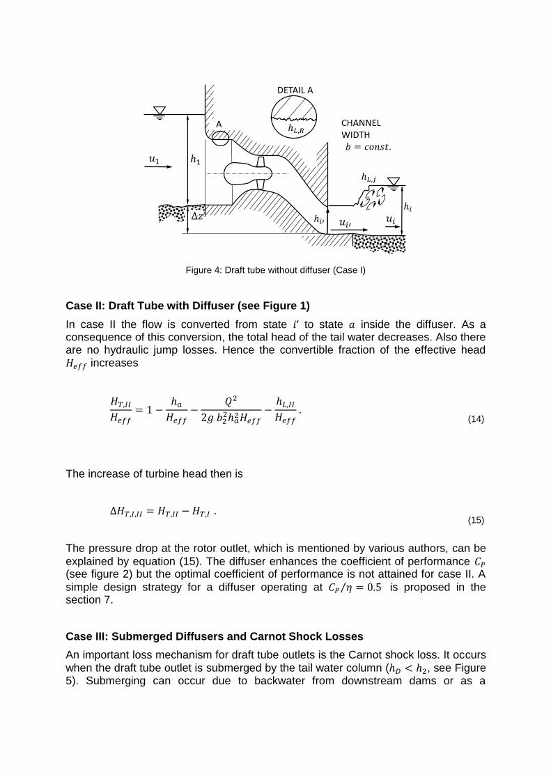
Case I: Draft tube without diffuser (see Figure 4)
In this case the index represents the position at the outlet of the draft tube without
diffuser. The velocity head at the turbine outlet ⁄ is comparatively high, while the
pressure head is low.
Point in Figure 3 i.e. Figure 4 is the tail water state of case I. The transition from
state to is known as hydraulic jump. For each total head within the codomain of
the total head for a given volume flow rate and √ ⁄ there are two
possible water depths. One of them with is called supercritical, the other with is subcritical. The highest possible difference in total head between head water and tail water occurs when the tail water flow is critical ( (see Figure 3)). This statement has been established by the second author [1].
In case I, the flow is supercritical at the draft tube outlet ( √ ⁄ >1). A
hydraulic jump occurs in between draft tube outlet and tail water (see Figure 4). The total head in the tail water is comparatively high. The shaft power is low due
to an inefficient operation point and high dissipative losses.
(13)
The dissipative losses related to the hydraulic jump from state to state , are
included in .For all of the cases considered in the present paper, the width of the
tail water is assumed to be the same ( ).
0 0.5 10
0.2
0.4
0.6
0.8
11
TOTAL HEAD
PR
ESSU
RE
HEI
GH
T
Figure 3: State diagram for open channel-flow
A
DETAIL A
CHANNEL WIDTH
Figure 4: Draft tube without diffuser (Case I)
Case II: Draft Tube with Diffuser (see Figure 1)
In case II the flow is converted from state to state inside the diffuser. As a consequence of this conversion, the total head of the tail water decreases. Also there are no hydraulic jump losses. Hence the convertible fraction of the effective head increases
(14)
The increase of turbine head then is
.
(15)
The pressure drop at the rotor outlet, which is mentioned by various authors, can be
explained by equation (15). The diffuser enhances the coefficient of performance (see figure 2) but the optimal coefficient of performance is not attained for case II. A
simple design strategy for a diffuser operating at ⁄ is proposed in the section 7.
Case III: Submerged Diffusers and Carnot Shock Losses
An important loss mechanism for draft tube outlets is the Carnot shock loss. It occurs
when the draft tube outlet is submerged by the tail water column ( , see Figure 5). Submerging can occur due to backwater from downstream dams or as a

consequence of the operating point of machines, i.e. volume flow rate of watercourses.
CHANNEL WIDTH
Figure 5: Submerged diffuser outlet
The Carnot shock loss can be established by strictly axiomatic equations. It is a consequence of the conservation of momentum and Bernoulli’s equation which itself can be established under use of the conservation of momentum [3]. The result of this derivation is the Carnot shock loss for an open channel-flow (see Figure 5) of
constant width , volume flow rate
(
)
(16)
With the dimensionless operating parameters and , defined in Figure 2, and the dimensionless diffuser outlet height
the dimensionless Carnot shock
loss reads
(
)
(17)
As a consequence of the first law of thermodynamics the hydraulic efficiency due to Carnot shock losses is
(18)
with Substituting equation (18) into equation (4) the
coefficient of performance with Carnot shock loss included is
(
) ⁄
(
) (19)

Figure 6 shows a grey contour plot for the coefficient of performance without
dissipative losses (see equation 4). The black lined contour plot in Figure 6, with the same values for isoclines, shows an exemplary coefficient of performance with Carnot shock loss included (see equation (19)). For this example the dimensionless diffuser outlet height
equals the optimal tail water height
. For values there is no Carnot shock loss, hence both contour plots
are identical ( ). For values nonzero Carnot shock losses
occur, hence for all values of dimensionless tail water height
and dimensionless tail water flow rate per width unit .
7 Diffuser Design for Optimal Operation
As it is mentioned in the first section the optimal operating point is established by [1]. A diffuser should be designed to work in this operating point. For a rectangular cross section at the outlet (see Figure 7), the optimal height of the diffuser is the optimal tail
water height (see Figure 2), hence
. The optimal
volume flow rate per width unit ⁄ ( ) ⁄
can be adjusted by
variation of the width of the diffuser. For optimal operation the width calculates
(20)
0 0.2 0.40
0.2
0.4
0.6
0.8
1
Figure 6: Coefficient of Performance with Carnot shock losses included
8 Conclusion
For an adequate discussion of efficiency in hydropower, the coefficient of performance is the measure to be discussed. Limitation on the discussion of hydraulic efficiency can be misleading.

For an adequate explanation of the function of a draft tubes diffuser, free surface effects have to be considered. These effects cannot be described by Bernoulli’s equation but by the first energy equation and mass conservation.
The geometry of the diffuser can contribute to achieve the optimal coefficient of
performance ⁄ .
Losses due to dissipation can be modelled analytically and be included in the coefficient of performance as it is shown in section 8. Then the gained energy can be calculated by consideration of operation point and dissipative losses.
Figure 7: Rectangular diffuser for optimal operation
References
[1] P. Pelz, „Upper Limit for Hydropower in an Open-Channel Flow,“ Journal of Hydraulic Engineering ASCE/; DOI: 10.1061/(ASCE) HY.1943-7900.0000393, November 2011.
[2] A. Betz, Zeitschrift für das gesamte Turbinenwesen, September 1920.
[3] E. Becker, Technische Strömungslehre, Stuttgart: Teubner, 1986.
[4] O. Cordier, „Ähnlichkeitsbedingungen für Strömungsmaschinen,“ Brennstoff-Wärme-Kraft, p. 337 ff., 1953.
[5] P. Pelz und M. Metzler, „OPtimization of Power-Specific Investment Costs for Small Hydropower,“ in 17. Internationales Seminar Wasserkraftanlagen, Wien, 2012.
[6] S. Deniz, in Saugrohre bei Flusskraftwerken, Zürich, Prof. Dr. Vischer, 1990, p. 68 ff..
[7] J. Raabe, in Hydro Power, Düsseldorf, VDI Verlag, 1989, p. 203 ff..
[8] A. Ruprecht, Finite Elemente zur Berechnung dreidimensionaler, turbulenter Strömungen in komplexen Geometrien, Stuttgart: Institut für Hydraulische Strömungsmaschinen, 1989.

[9] J. Giesecke und E. Mosonyi, in Wasserkraftanlagen - Planung, Bau und Betrieb, Heidelberg, Springer Verlag, 2009, p. 539 ff..
Author(s)
Manuel Metzler
Technische Universität Darmstadt
Institut für Fluidsystemtechnik
Magdalenenstraße 4, 64289 Darmstadt
Phone: +49-6151-16-3353 FAX: +49-6151-16-2453
E-mail: [email protected]
Univ.-Prof. Dr.-Ing. Peter F. Pelz
Technische Universität Darmstadt
Institut für Fluidsystemtechnik
Magdalenenstraße 4, 64289 Darmstadt
Phone: +49-6151-16-2153 FAX: +49-6151-16-2453
E-mail: [email protected]