compliant centrifugal clutches: design, analysis, and testing
TRANSCRIPT

Brigham Young University Brigham Young University
BYU ScholarsArchive BYU ScholarsArchive
Theses and Dissertations
2003-09-29
Compliant Centrifugal Clutches: Design, Analysis, and Testing Compliant Centrifugal Clutches: Design, Analysis, and Testing
Nathan B. Crane Brigham Young University - Provo
Follow this and additional works at: https://scholarsarchive.byu.edu/etd
Part of the Mechanical Engineering Commons
BYU ScholarsArchive Citation BYU ScholarsArchive Citation Crane, Nathan B., "Compliant Centrifugal Clutches: Design, Analysis, and Testing" (2003). Theses and Dissertations. 79. https://scholarsarchive.byu.edu/etd/79
This Thesis is brought to you for free and open access by BYU ScholarsArchive. It has been accepted for inclusion in Theses and Dissertations by an authorized administrator of BYU ScholarsArchive. For more information, please contact [email protected].

COMPLIANT CENTRIFUGAL CLUTCHES: DESIGN, ANALYSIS, AND TESTING
by
Nathan B. Crane
A thesis submitted to the faculty of
Brigham Young University
in partial fulfillment of the requirements for the degree of
Master of Science
Department of Mechanical Engineering
Brigham Young University
December 1999

BRIGHAM YOUNG UNIVERSITY
GRADUATE COMMITTEE APPROVAL
of a thesis submitted by
Nathan B. Crane
This thesis has been read by each member of the following graduate committee and by majority vote has been found to be satisfactory.
_________________________ ___________________________________Date Larry L. Howell, Chair
_________________________ ___________________________________Date Kenneth W. Chase
_________________________ ___________________________________Date Timothy W. McLain

BRIGHAM YOUNG UNIVERSITY
As chair of the candidate’s graduate committee, I have read the thesis of Nathan B. Crane in its final form and have found that (1) its format citations, and bibliographical style are consistent and acceptable and fulfill university and department style requirements; (2) its illustrative materials including figures, tables, and charts are in place; and (3) the final manuscript is satisfactory to the graduate committee and is ready for submission to the university library.
_________________________ ___________________________________Date Larry L. Howell
Chair, Graduate Committee
Accepted for the Department
___________________________________Craig C. SmithGraduate Coordinator
Accepted for the College
___________________________________Douglas M. ChabriesDean, College of Engineering and Technology

ABSTRACT
COMPLIANT CENTRIFUGAL CLUTCHES: DESIGN, ANALYSIS, AND TESTING
Nathan B. Crane
Department of Mechanical Engineering
Master of Science
Existing classes of centrifugal clutch concepts were reviewed. The pseudo-rigid-
body model (PRBM), rigid-body replacement synthesis, force-deflection analysis, compli-
ance potential evaluation, and compliant concept evaluation were used to develop effec-
tive new centrifugal clutch concepts. These methods helped develop and model four novel
compliant centrifugal clutch designs, model two existing designs, and identify a concept
with excellent potential for low-cost centrifugal clutch applications. This concept, the
floating opposing arm (FOA) clutch, doubles the torque capacity metric relative to
existing compliant designs. Torque and engagement speed models for this clutch were
developed and verified against four prototype clutches. Additional novel designs devel-
oped through this work have lower torque capacities, but also show good potential
because of other unique characteristics. All of the designs were prototyped and tested to
measure their torque-speed relationships.

ACKNOWLEDGEMENTS
The author wishes to acknowledge the gracious support of the many people that
contributed to this work both directly and indirectly.
A great debt is owed to Dr. Larry L. Howell for his guidance and instruction in
helping me through all of the phases of this work. His mentoring and example have been
and will yet be invaluable. The time and effort of Dr. Kenneth Chase and Dr. Timothy
McLain as committee members are greatly appreciated.
Brent Weight helped tremendously in his long efforts to prototype the many odd
geometries developed, develop testing software, and assist in the testing. Scott Lyon’s
skills were invaluable in developing the signal conditioning circuits and going to great
lengths to solve problems with the data acquisition equipment. Everyone in the lab has
been a great support suggesting solutions to occasional problems and setting a fine
example through their research and love of learning.
Without my parents early support and encouragement, I never would have made it
this far. Most of all, thanks to my supportive wife for her continual support and encour-
agement as well as her many hours of careful proofreading. Her work both in proofreading
and encouraging me to do my best, has greatly improved this thesis.
This work has been funded in part through a National Science Foundation graduate
fellowship and by a National Science Foundation Career Award, No. DMI-9624574.

vi
Table of Contents
CHAPTER 1 Introduction....................................................................................................1
1.1 Thesis Statement ......................................................................................................1
1.2 Background..............................................................................................................1
1.2.1 Centrifugal Devices ........................................................................................1
1.2.2 Centrifugal Clutches .......................................................................................4
1.2.3 Overspeed Brakes ...........................................................................................6
1.2.4 Compliant Mechanisms ..................................................................................7
1.3 Research Approach ..................................................................................................8
1.4 Research Benefits ..................................................................................................11
1.5 Literature Review ..................................................................................................12
1.5.1 Centrifugal Devices ......................................................................................12
1.5.2 Mechanism Synthesis and Design ................................................................15
1.5.3 Compliant Mechanisms ................................................................................15
1.6 Thesis Outline ........................................................................................................19
CHAPTER 2 Centrifugal Device Background ..................................................................21
2.1 Centrifugal Device Design.....................................................................................21
2.1.1 Important Issues in Centrifugal Device Design ............................................21
2.1.2 Advantages....................................................................................................24

vii
2.1.3 Disadvantages ...............................................................................................24
2.2 Types of Centrifugal Clutches ...............................................................................25
2.2.1 Flexible Trailing Shoe...................................................................................25
2.2.2 Connected Shoes...........................................................................................26
2.2.3 Floating Shoes...............................................................................................28
2.2.4 Oil Clutch......................................................................................................28
2.2.5 Mercury Clutch .............................................................................................29
2.2.6 Ball & Cone Clutch.......................................................................................30
2.2.7 Dry Fluid.......................................................................................................30
2.3 Two Evaluation Types............................................................................................32
2.4 Compliance Potential Evaluation...........................................................................33
2.4.1 Evaluation Results ........................................................................................33
2.4.2 Discussion of Most Promising Clutch Types................................................33
CHAPTER 3 Centrifugal Clutch Evaluation Procedures and Criteria...............................37
3.1 Clutch Evaluation Procedure .................................................................................37
3.2 Evaluation Criteria .................................................................................................38
3.2.1 Berglund Criteria ..........................................................................................38
3.2.2 Criteria Adapted from Berglund for Use in this Work..................................39
3.2.3 Additional Criteria for Centrifugal Clutches ................................................41
3.2.4 Clutch Rating Methods .................................................................................48
3.3 Clutch Testing ........................................................................................................49
3.3.1 Test Setup......................................................................................................49
3.3.2 Test Procedures .............................................................................................53

viii
3.3.3 Error Sources ................................................................................................53
CHAPTER 4 Compliant Centrifugal Clutch Designs........................................................57
4.1 Existing Compliant Designs ..................................................................................58
4.1.1 Conventional Compliant Centrifugal Clutch (C4) ........................................58
4.1.2 S-Clutch ........................................................................................................63
4.2 Novel Compliant Designs ......................................................................................66
4.2.1 Floating 1 (F1) ..............................................................................................66
4.2.2 Floating Opposing Arm ................................................................................71
4.2.3 Grounded Opposing Arm..............................................................................74
4.2.4 Split-arm .......................................................................................................78
4.3 Summary of Clutch Test Results............................................................................82
4.4 Clutch Concept Evaluations...................................................................................82
CHAPTER 5 FOA Clutch Model and Application............................................................85
5.1 Engagement Model ................................................................................................85
5.1.1 Equation Development .................................................................................85
5.1.2 Initial Test Data.............................................................................................88
5.1.3 Engagement Speed Retest.............................................................................91
5.2 FOA Torque Model................................................................................................92
5.2.1 Equation Development .................................................................................92
5.2.2 Test Data .......................................................................................................95
5.3 Other Design Issues ...............................................................................................95
5.3.1 Wear ..............................................................................................................95
5.3.2 Material Selection .........................................................................................97

ix
5.3.3 Torque Dependence on Coefficient of Friction.............................................98
5.4 FOA Concept Enhancement ................................................................................102
5.4.1 Reducing Effect of Clutch-Hub Clearance .................................................102
5.4.2 Using the Clutch-hub Clearance Effect ......................................................102
5.5 String Trimmer Design Example .........................................................................103
5.5.1 Design Requirements ..................................................................................103
5.5.2 Proposed Design .........................................................................................104
5.5.3 Design Predictions ......................................................................................104
5.5.4 Prototype Testing ........................................................................................105
5.5.5 FOA String Trimmer Conclusions..............................................................107
CHAPTER 6 Conclusions and Recommendations ..........................................................109
6.1 Contributions .......................................................................................................109
6.1.1 Modeling Two Existing Clutches................................................................109
6.1.2 Floating Opposing Arm (FOA) Clutch.......................................................110
6.1.3 Split-Arm Clutch.........................................................................................110
6.1.4 Demonstration of Compliant Mechanism Techniques................................111
6.2 Recommendations................................................................................................111
6.2.1 Advance the Promising Novel Designs ......................................................111
6.2.2 Apply the Clutch Concepts to Overspeed Brakes.......................................111
6.2.3 Explore Other Centrifugal Clutch Concepts ...............................................112
6.2.4 Improve Torque Model ...............................................................................115
6.3 Conclusion ...........................................................................................................115
REFERENCES ............................................................................................................... 117

x
APPENDIX A Pseudo Rigid Body Model ......................................................................125
A.1 PRBM Overview.................................................................................................125
A.2 Small Length Flexural Pivot ...............................................................................126
A.3 Cantilever Beam with Force at Free End............................................................129
A.4 Cantilever Beam with End Moment Loading .....................................................131
APPENDIX B Experiment Data......................................................................................133
B.1 Calibrations .........................................................................................................133
B.1.1 Torque Sensor.............................................................................................133
B.1.2 Tachometer .................................................................................................134
B.2 Friction Coefficient .............................................................................................135
B.3 Bearing Torques ..................................................................................................135
B.4 Oscillations in Test Setup at Start-up ..................................................................138
B.5 Conventional Compliant Centrifugal Clutch (C4)...............................................138
B.5.1 C4 #1...........................................................................................................138
B.5.2 C4 #2...........................................................................................................138
B.5.3 C4 #3...........................................................................................................141
B.6 S-clutch ...............................................................................................................141
B.6.1 S-clutch #1 .................................................................................................141
B.6.2 S-clutch #2 .................................................................................................141
B.7 F1 Clutch.............................................................................................................141
B.7.1 F1 clutch #1................................................................................................141
B.8 Floating Opposing Arm (FOA) Clutch ...............................................................141

xi
B.8.1 FOA #1.......................................................................................................141
B.8.2 FOA #2.......................................................................................................141
B.8.3 FOA #3.......................................................................................................141
B.8.4 FOA #4.......................................................................................................141
B.9 Grounded Opposing Arm (GOA) Clutch............................................................150
B.9.1 GOA #1 ......................................................................................................150
B.9.2 GOA #2 ......................................................................................................150
B.10 Split-arm Clutch ................................................................................................150
B.10.1 Split-arm #1..............................................................................................150
B.10.2 Split-arm #2..............................................................................................150
B.10.3 Split-arm #3..............................................................................................156

xii
List of Tables
TABLE 2-1 Compliance Criteria Evaluation of Centrifugal Clutch Types (Berglund, 1998) . . . . . . . . . . . . . . . . . . . . . . . . . . . . . . . . . . . . . . . . . . . . . . . . 34
TABLE 3-1 Definition of Clutch Ratings . . . . . . . . . . . . . . . . . . . . . . . . . . . . . . 48
TABLE 4-1 Parameter values for C4 test clutches. . . . . . . . . . . . . . . . . . . . . . . 62
TABLE 4-2 Parameter values for prototype S-clutches. . . . . . . . . . . . . . . . . . . 65
TABLE 4-3 Parameter values for prototype F1 clutch . . . . . . . . . . . . . . . . . . . . 70
TABLE 4-4 Parameter values for prototype FOA. . . . . . . . . . . . . . . . . . . . . . . . 75
TABLE 4-5 Parameter values for prototype GOA clutches. . . . . . . . . . . . . . . . 77
TABLE 4-6 Parameter values for prototype Split-arm clutches. . . . . . . . . . . . . 81
TABLE 4-7 Clutch Test Result Summary . . . . . . . . . . . . . . . . . . . . . . . . . . . . . 82
TABLE 4-8 Clutch Concept Evaluation Results . . . . . . . . . . . . . . . . . . . . . . . . 83
TABLE 5-1 Measured and predicted engagement values for FOA clutches. . . . 88
TABLE 5-2 Measured and predicted torque capacities (Tb) for FOA clutches. . 95
TABLE 5-3 Critical Coefficient of Friction for Self-Locking . . . . . . . . . . . . . 101
TABLE 5-4 Design Requirements for FOA string trimmer clutch. . . . . . . . . . 104
TABLE 5-5 Parameter values for String Trimmer FOA. . . . . . . . . . . . . . . . . . 105
TABLE B-1. Tachometer Calibration Data . . . . . . . . . . . . . . . . . . . . . . . . . . . . 135
xiii
List of Figures
Figure 1-1 (a) Body rotating at a constant angular velocity and pinned at its center of mass. (b) The motion equations using the standard form of Newton’s Second Law. (c) The motion equations using D’Alembert’s Principle and centrifugal forces are shown. . . . . . . . . . . . . . . . . . . . . . . . . . . . . . 2
Figure 1-2 Torque and current versus time of an AC motor with a conventional and a time-delay centrifugal clutch. Current draw is dramatically reduced for both clutch types. The time-delay clutch reduces initial torques to in-crease the starting smoothness (St. John, 1979). . . . . . . . . . . . . . . . . . 5
Figure 1-3 A rigid-body connected-shoe clutch with three shoes. . . . . . . . . . . . . . 6
Figure 1-4 Two centrifugal clutches. (a) The rigid-body clutch consists of at least 13 parts. (b) The compliant clutch is just one piece. Both clutches trans-mit torque when clutch members move outward due to centrifugal force. As they move outward, they contact a drum and transmit torque. . . . . 8
Figure 1-5 (a) A complaint parallel motion mechanism and (b) its pseudo-rigid-body model. . . . . . . . . . . . . . . . . . . . . . . . . . . . . . . . . . . . . . . . . . . . . . 8
Figure 1-6 Flowchart of the research approach. . . . . . . . . . . . . . . . . . . . . . . . . . . . 9
Figure 1-7 A compliant centrifugal clutch. This clutch is well suited to production by powder metallurgy. It is commonly referred to as an “S-clutch” (Suchdev & Campbell, 1989). . . . . . . . . . . . . . . . . . . . . . . . . . . . . . . 14
Figure 1-8 A Compliant ratchet and pawl clutch with centrifugal throw-out (Roach, 1998) . . . . . . . . . . . . . . . . . . . . . . . . . . . . . . . . . . . . . . . . . . . . . . . . . . 14
Figure 2-1 Compliant-centrifugal device trade-offs. (a) The compliant mechanism is more flexible due to the longer segments, but has a smaller actuation force due to the smaller mass. (b) The mechanism has a larger actuation force, but shorter, stiffer members.. . . . . . . . . . . . . . . . . . . . . . . . . . . 23
Figure 2-2 Flexible Trailing Shoe Centrifugal Clutch. The weighted steel band de-flects to contact the drum as the clutch accelerates. The clutch torque output is less sensitive to changes in the coefficient of friction than are most types. . . . . . . . . . . . . . . . . . . . . . . . . . . . . . . . . . . . . . . . . . . . . . 26
Figure 2-3 Connected Shoe Centrifugal Clutch. The arrow indicates non-aggres-sive rotation direction. . . . . . . . . . . . . . . . . . . . . . . . . . . . . . . . . . . . . 27
Figure 2-4 Floating Shoe Centrifugal Clutch. . . . . . . . . . . . . . . . . . . . . . . . . . . . 28

xiv
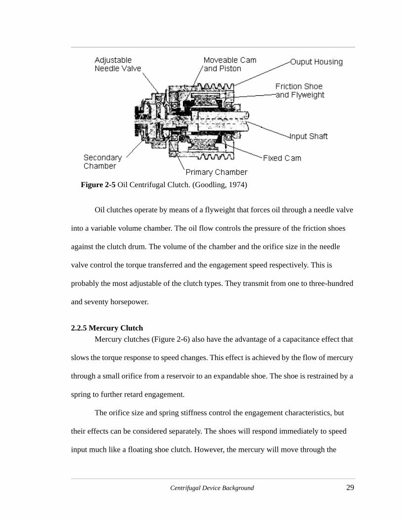
Figure 2-5 Oil Centrifugal Clutch. (Goodling, 1974). . . . . . . . . . . . . . . . . . . . . . 29
Figure 2-6 Mercury Centrifugal Clutch. The mercury flows from the reservoir to the expandable shoe to help force the shoe against the drum. . . . . . . 30
Figure 2-7 Ball & Cone Centrifugal Clutch. The Centrifugal balls cam the bronze rings outward to transmit torque through friction with the output hous-ing. (Goodling, 1974) . . . . . . . . . . . . . . . . . . . . . . . . . . . . . . . . . . . . . 31
Figure 2-8 Dry Fluid Centrifugal Clutch. At rated speed, the steel shot packs be-tween the rotor and the output housing to transmit torque. . . . . . . . . 31
Figure 3-1 These graphs compare the adequacy of the model in describing the torque performance of the tested clutches. The model has a maximum error of nine percent for the poor fit graph. . . . . . . . . . . . . . . . . . . . . 45
Figure 3-2 A compliant centrifugal clutch with cotton webbing glued on the contact surface. . . . . . . . . . . . . . . . . . . . . . . . . . . . . . . . . . . . . . . . . . . . . . . . . 50
Figure 3-3 Measuring the coefficient of friction. . . . . . . . . . . . . . . . . . . . . . . . . . 50
Figure 3-4 (a,b) Clutch test setup. (a,c) The tachometer measures the clutch speed. (a,d) The clutch spins inside the stationary clutch drum. (a,d) The output torque is measured be the reaction torque gauge mounted between the tailstock and the clutch drum. The clutch drum is mounted on the driving shaft with bearings. . . . . . . . . . . . . . . . . . . . . . . . . . . . . . . . . . . . . . . . 52
Figure 3-5 Test data from a representative clutch torque test. . . . . . . . . . . . . . . . 54
Figure 4-1 (a)Conventional Compliant Centrifugal Clutch in its undeflected and deflected positions, (b) force and distance vectors for torque equations, (c) vectors and angles used in the contact equations. . . . . . . . . . . . . . 59
Figure 4-2 The parameterization of a C4 clutch. . . . . . . . . . . . . . . . . . . . . . . . . . 62
Figure 4-3 An S-clutch. The longer flexible segments help reduce the bending stress relative to a comparable C4 clutch. . . . . . . . . . . . . . . . . . . . . . . 63
Figure 4-4 S-clutch analysis. (a) The applied forces on the clutch arm. (b) The ap-plied forces on the flexible segment. A moment is required for equiva-lence since the forces were moved. (c) The PRBM of the clutch arm. The arm is divided into two segments, one for the rigid segment and one for the flexible segment. However, the angle of the second link (θo) is a function of the angle of the first link (Θ).. . . . . . . . . . . . . . . . . . . . . . 64
Figure 4-5 A F1 type centrifugal clutch. (a) The clutch is pictured with its center hub. (b) The clutch’s PRBM and applied centrifugal forces are shown. (c) The forces on a clutch segment before engagement and (d) after en-gagement when the center of mass lies on the bisector of α. . . . . . . . 67
Figure 4-6 (a) A FOA clutch in its undeflected position. (b) The PRBM of the clutch with the centrifugal forces shown. (c) The applied forces deflec-tion path before contact of a single shoe and its PRBM. (d) The applied

xv
forces and deflected position of a single shoe and its PRBM after con-tact. (Deflections are shown larger than actual deflections.) . . . . . . . 71
Figure 4-7 Parameter values for the FOA clutches. . . . . . . . . . . . . . . . . . . . . . . . 74
Figure 4-8 Grounded Opposing Arm (GOA) Clutch. (a) A GOA clutch with three arm pairs. (b) A schematic of a FEA model of the clutch before contact. (c) An approximate PRBM for the clutch before contact. . . . . . . . . . 75
Figure 4-9 Diagram of parameter definitions for the GOA clutch. . . . . . . . . . . . 78
Figure 4-10 The Split-arm clutch. (a) A two arm, six segment clutch. (b) A one arm, thirteen segment clutch. (c) The PRBM of a clutch arm with k segments with the centrifugal forces included. (d) Variables used in the deflection analysis of the clutch. . . . . . . . . . . . . . . . . . . . . . . . . . . . . . . . . . . . . . 78
Figure 5-1 Explanation of variables used in the FOA clutch engagement model. 86
Figure 5-2 Polypropylene stress strain curves for different specimen sizes and pull rates. The slope of the curves varies by a factor of two due to the varia-tions in specimen size and pull rate (Cook & Parker, 1996). . . . . . . . 89
Figure 5-3 (a) The assumed symmetrical position of the FOA clutch before engage-ment. The floating piece is centered on the hub with even spacing all the way around. (b) A likely configuration of the clutch before engagement. A non-symmetrical force such as gravity has caused the floating piece to rest against the hub on one side. . . . . . . . . . . . . . . . . . . . . . . . . . . . 90
Figure 5-4 Parameters used in calculating Tb factor for the FOA clutches. (a) Ex-ternal forces and appropriate position vectors. (b) Free body diagrams of the two links.. . . . . . . . . . . . . . . . . . . . . . . . . . . . . . . . . . . . . . . . . . . . 92
Figure 5-5 Variation of torque capacity with the coefficient of friction for the FOA #3 clutch.. . . . . . . . . . . . . . . . . . . . . . . . . . . . . . . . . . . . . . . . . . . . . . . 99
Figure 5-6 Torque capacity versus coefficient of friction for the FOA #3 clutch. The torque capacity approaches infinity when the coefficient of friction is at the critical value for self-locking. . . . . . . . . . . . . . . . . . . . . . . . 101
Figure 5-7 Two S-clutches from a Homelite Versatool string trimmer. The outer di-ameter of the clutches is 2.41 inches. . . . . . . . . . . . . . . . . . . . . . . . . 103
Figure 5-8 (a) The prototype FOA clutch for the string trimmer. (b) The FOA clutch mounted on the string trimmer.. . . . . . . . . . . . . . . . . . . . . . . . . . . . . 106
Figure 6-1 A patented clutch concept that reduces torque at high speeds. The joints near the rotational axis are weighted to overcome the restraining springs to move outward at high speeds. Small forces at the weights have a large effect because the links are near toggle. . . . . . . . . . . . . . . . . . . . . . . 113
Figure 6-2 (a) A clutch concept with improved starting smoothness. (b) A PRBM for half of the clutch showing the two counteracting input forces that would slow the clutch’s torque response. . . . . . . . . . . . . . . . . . . . . . 115
Figure A-1 A small length flexural pivot. . . . . . . . . . . . . . . . . . . . . . . . . . . . . . . 127

xvi
Figure A-2 A small length flexural pivot in its undeflected and deflected positions and the corresponding pseudo rigid body model. . . . . . . . . . . . . . . . 128
Figure A-3 A cantilever beam with end forces and its pseudo rigid body model. Both are shown in their deflected and undeflected positions. . . . . . 130
Figure A-4 A cantilever beam with an end moment load is shown with its corre-sponding pseudo rigid body model. . . . . . . . . . . . . . . . . . . . . . . . . . 132
Figure B-1 Bearing torque data from six tests. The solid line is the best-fit line for the bearing data used for subtracting off the bearing torque. . . . . . . 136
Figure B-2 Bearing data with unusual values. The peak values are far in excess of the expected torques for the bearings. . . . . . . . . . . . . . . . . . . . . . . . 137
Figure B-3 Experimental Data for C4 clutch #1.. . . . . . . . . . . . . . . . . . . . . . . . . 139
Figure B-4 Test data for C4 clutch #2. . . . . . . . . . . . . . . . . . . . . . . . . . . . . . . . . 140
Figure B-5 Test data for C4 clutch #3. . . . . . . . . . . . . . . . . . . . . . . . . . . . . . . . . 142
Figure B-6 S-clutch #1 data. . . . . . . . . . . . . . . . . . . . . . . . . . . . . . . . . . . . . . . . . 143
Figure B-7 S-clutch #2 data. . . . . . . . . . . . . . . . . . . . . . . . . . . . . . . . . . . . . . . . . 144
Figure B-8 F1 clutch #1 data from two speed cycles. . . . . . . . . . . . . . . . . . . . . . 145
Figure B-9 FOA clutch #1 data. . . . . . . . . . . . . . . . . . . . . . . . . . . . . . . . . . . . . . 146
Figure B-10 FOA clutch #2 data. . . . . . . . . . . . . . . . . . . . . . . . . . . . . . . . . . . . . . 147
Figure B-11 FOA clutch #3 data. . . . . . . . . . . . . . . . . . . . . . . . . . . . . . . . . . . . . . 148
Figure B-12 FOA clutch #4 initial results. . . . . . . . . . . . . . . . . . . . . . . . . . . . . . . 149
Figure B-13 FOA clutch #4 secondary results. . . . . . . . . . . . . . . . . . . . . . . . . . . . 151
Figure B-14 GOA clutch #1 data. . . . . . . . . . . . . . . . . . . . . . . . . . . . . . . . . . . . . . 152
Figure B-15 GOA clutch #2 data. . . . . . . . . . . . . . . . . . . . . . . . . . . . . . . . . . . . . . 153
Figure B-16 Split-arm clutch #1 data. . . . . . . . . . . . . . . . . . . . . . . . . . . . . . . . . . . 154
Figure B-17 Split-arm clutch #2 data. . . . . . . . . . . . . . . . . . . . . . . . . . . . . . . . . . . 155
Figure B-18 Split-arm clutch #3 data. . . . . . . . . . . . . . . . . . . . . . . . . . . . . . . . . . . 157

1
CHAPTER 1 Introduction
1.1 Thesis Statement
This thesis shows that the principles of compliant mechanism technology can be
used to develop and analyze cost-effective centrifugal clutch configurations. Two pre-
existing and four novel compliant centrifugal clutch configurations are presented. A basic
model of each design is developed and the results of prototype testing are discussed. The
relative merits of the different designs are discussed and several applications are
demonstrated.
1.2 Background
1.2.1 Centrifugal DevicesA centrifugal device is actuated by centrifugal force. However, in a strict sense,
centrifugal force does not exist, but the term is used because it provides an intuitive way to
consider normal accelerations due to constant rotational velocity. Other related terms
include centripetal forces, D’Alembert forces, inertial forces and centripetal acceleration.
To avoid confusion, each of these terms is reviewed.

2 Compliant Centrifugal Clutches: Design, Analysis, and Testing
A body moving in a circular motion with a constant angular velocity (ω )
accelerates continuously due to its constantly changing direction of motion. Figure 1-1(a)
shows such a body. The acceleration vector is oriented toward the center of the circular
motion and its magnitude is
(1.1)
This acceleration is termed centripetal or normal acceleration. The force exerted to cause
this acceleration is called centripetal force (Figure 1-1(b)). Applying Newton’s second
law, the centripetal force is
(1.2)
Centripetal forces are also directed toward the center of rotation.
The equilibrium equation for a body rotating at a uniform angular velocity with
arbitrary additional forces is
Figure 1-1 (a) Body rotating at a constant angular velocity and pinned at its center of mass. (b) The motion equations using the standard form of Newton’s Second Law. (c) The motion equations using D’Alembert’s Principle and centrifugal forces are shown.
(a) (b) (c)
ω
ω
acentripeta l
Fcentripetal
Fcentripetal = m * acentripetal
m * acentripetal
ωFcentripetal
Fcentrifugal = - m * acentrifugal
Fcentripetal + Fcentrifugal = 0
Fcentripetal - m * acentripetal = 0
= =
Dynamic Equilibrium & D'Alembert's PrincipleNewton's Second Law
a ω2r=
Fcentripetal mω2r=

Introduction 3
(1.3)
This equation may be rearranged as
(1.4)
where the term is termed an inertial or D’Alembert force. It has the units of
force, and is directed opposite to the centripetal acceleration. D’Alembert’s principle
states the equivalency of equations (1.3) and (1.4). Centrifugal force is the D’Alembert
force caused by the centripetal acceleration of a rotating body. It is expressed as
(1.5)
For most solid objects, the centrifugal force can be considered a function of
rotational velocity only because mass is constant and generally, the radius is nearly
constant. Thus centrifugal force is a useful actuation force for many applications requiring
a response to rotational velocity. Centrifugal force actuated devices are simple,
inexpensive solutions to clutch and switch applications since they require no outside
power source or signal for control or actuation.
Many thousands of centrifugal devices are produced annually. Their applications
range from yoyos to industrial facilities. Many of these devices are relatively simple and
have changed little over the past twenty years. This work systematically applies the
principles of compliant mechanism design to these centrifugal devices so that they may
benefit from recent advances in compliant mechanism technology.
F∑ ma mω2r= =
F mω2r–( )+∑ 0=
mω2r–( )
Fcentrifugal mω2r–=

4 Compliant Centrifugal Clutches: Design, Analysis, and Testing
1.2.2 Centrifugal ClutchesCentrifugal clutches transmit torque as a function of the driving speed. The
actuation force and control are provided by centrifugal forces on the clutch. This work
seeks to develop novel centrifugal clutch configurations with increased torque capacity
and/or load acceleration smoothness while maintaining a cost advantage over rigid-body
designs. A successful design increases these performance parameters and/or decreases
production costs. Centrifugal clutches are constrained by many factors such as heat, wear,
load capacity, and space.
Centrifugal clutches reduce starting torques on AC motors, reduce loads on
internal combustion engines at idle speeds, and provide overload protection. They can also
isolate torsional vibrations. In many applications, the clutches provide adequate load
acceleration and control with minimal expense. Their use can also decrease required
motor size by decreasing the current draw of motors accelerating a high-inertia load. This
is accomplished by reducing the required torque output at speeds where the motor is least
able to generate torque. Figure 1-2 compares torque output and current draw of an electric
motor with and without a centrifugal clutch.
Each year, centrifugal clutches provide power transmission and/or control for
thousands of string trimmers, chainsaws, radio-controlled cars and helicopters, and go-
karts. They also control torque transmission in large industrial motors transmitting
hundreds or even thousands of horsepower. These applications use centrifugal clutches
due to their simplicity and low cost relative to competing solutions such as magnetic,
electric, and pneumatic clutches. However, the simplicity of the centrifugal clutch also

Introduction 5
limits the range of torque control possible from a given clutch. This limits their use in
applications demanding smoother starts, or with varying starting conditions.
The squared relationship between torque and speed means there is a cubic
relationship between speed and transmitted power. This can be an advantage or
disadvantage depending on the application. An apparently small deviation in operating
speed can result in a very large change in maximum transmitted power. A clutch should be
sized so that no components will be damaged if the clutch transmits its maximum torque.
Centrifugal clutches are friction clutches. As such, wear and heating during load
acceleration is an important concern. Clutches may also have problems due to variation in
the friction conditions that modify the expected torque-speed relationship. However,
centrifugal clutches are very efficient under operating conditions because there is no
slippage in the clutch after the load is accelerated. However, if torque increases beyond
Figure 1-2 Torque and current versus time of an AC motor with a conventional and a time-delay centrifugal clutch. Current draw is dramatically reduced for both clutch types. The time-delay clutch reduces initial torques to increase the starting smoothness (St. John, 1979).

6 Compliant Centrifugal Clutches: Design, Analysis, and Testing
the clutch’s capacity, it will slip harmlessly. This protects motors and other more
expensive components from damage due to excessive torque.
A common centrifugal clutch design is the connected shoe design shown in Figure
1-3. As the clutch speeds up, the arms deflect outward. The movement may be resisted by
springs to raise the speed at which the clutch begins transmitting torque. When the arms
contact the cylindrical drum that surrounds them, they begin to transmit torque. Torque
transfer capacity will continue to increase as the speed increases.
1.2.3 Overspeed BrakesSome overspeed brakes are based on centrifugal clutches. Centrifugal clutches are
well suited to this applications since speed is the input. The variation of centrifugal force
with the speed squared can be a very positive factor in these devices. This relationship
would ensure that the brake torque and power dissipation increase quickly until the brake
halts the acceleration of the system. This effect could be amplified by the use of a brake
Figure 1-3 A rigid-body connected-shoe clutch with three shoes.
Clutch Drum
Driving Shaft
OptionalSpringLocation
Shoe Hub

Introduction 7
with centrifugal switching action so that the brake “snapped” on. However, this could also
cause significant shock loading.
Overspeed brakes are not addressed in detail here because they are simply a
kinematic inversion of a centrifugal clutch. A centrifugal overspeed brake is a centrifugal
clutch with the output fixed to a frame. Any of the clutches discussed in this work could be
modified for use as an overspeed brake.
1.2.4 Compliant MechanismsCompliant mechanisms are mechanisms that obtain some or all of their motion
through the deflection of their members. In a compliant mechanism, a single flexible link
often replaces two or more rigid links of an equivalent rigid-body mechanism. This
decreases the mechanism’s part count, wear points, and backlash. Due to these
advantages, compliant mechanisms have been used in both inexpensive mass-produced
parts and low-volume precision parts. Compliant configurations of centrifugal devices
may decrease manufacturing costs compared to rigid-body designs. Their lower cost may
also allow new applications of centrifugal devices in low-cost products. Compare the
rigid-body and compliant clutch designs in Figure 1-4. This clutch demonstrates part
count reduction through compliant mechanism technology.
The advantages of compliant mechanisms come with increased design challenges.
These challenges include analyzing nonlinear deflections and increased fatigue-failure
concerns. The pseudo-rigid-body model (PRBM) translates compliant mechanisms into
nearly equivalent rigid-body mechanisms for early analysis and synthesis. Figure 1-5
shows a compliant mechanism and its PRBM. Using the PRBM, compliant mechanisms

8 Compliant Centrifugal Clutches: Design, Analysis, and Testing
can be designed and analyzed as rigid-body mechanisms without calculating large beam
deflections.
1.3 Research Approach
This work brings together many recent developments in compliant mechanism
design. The work combines the basic PRBM techniques with rigid-body replacement
synthesis, recent work in evaluation of compliance potential, and new tools for evaluating
different compliant designs. The research procedure and the relationship of these different
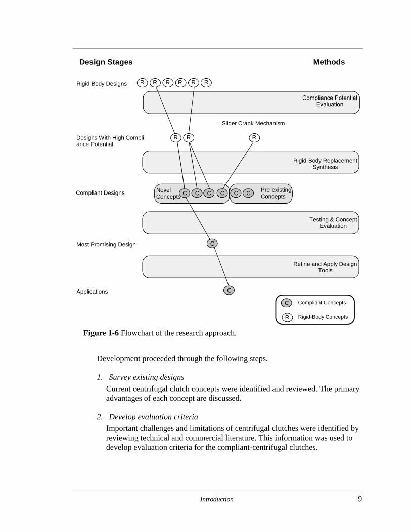
procedures are outlined in Figure 1-6 and discussed below.
Figure 1-4 Two centrifugal clutches. (a) The rigid-body clutch consists of at least 13 parts while (b) the compliant clutch is just one piece. Both clutches transmit torque when clutch members move outward due to centrifugal force. As they move outward, they contact a drum and transmit torque.
Rigid-Body Clutch Compliant Clutch
(a) (b)
TorsionalSprings
Figure 1-5 (a) A complaint parallel motion mechanism and (b) its pseudo-rigid-body model.
(a) (b)
Introduction 9
Development proceeded through the following steps.
1. Survey existing designs
Current centrifugal clutch concepts were identified and reviewed. The primary advantages of each concept are discussed.
2. Develop evaluation criteria
Important challenges and limitations of centrifugal clutches were identified by reviewing technical and commercial literature. This information was used to develop evaluation criteria for the compliant-centrifugal clutches.
Figure 1-6 Flowchart of the research approach.
R RRRRR
C Compliant Concepts
R Rigid-Body Concepts
Rigid Body Designs
Designs With High Compli-ance Potential
Compliant Designs
Most Promising Design
Applications
Rigid-Body ReplacementSynthesis
Testing & ConceptEvaluation
RR R
Slider Crank Mechanism
NovelConcepts
Pre-existingConcepts
Design Stages Methods
Refine and Apply DesignTools
CCCCCC
C
C

10 Compliant Centrifugal Clutches: Design, Analysis, and Testing
3. Evaluate compliance potential of the rigid-body designs
Compliance potential criteria developed by Roach & Howell (1999) and Ber-glund (1998) were used to identify which centrifugal clutch concepts are most adaptable to compliant mechanisms.
4. Develop compliant designs by rigid-body replacement
Compliant centrifugal clutches were developed from concepts that scored well in the compliance criteria evaluation. They were developed by rigid-body- replacement synthesis. Using this method, multiple compliant mechanisms were be generated from a single rigid-body concept.
5. Explore other novel compliant configurations
As the mechanisms generated above were evaluated, other concepts were devel-oped to overcome their limitations. Common mechanism types such as four-bars and double sliders were surveyed for other promising compliant designs.
6. Prototype designs and collect test data to identify any unique characteristics of a design
The new designs were prototyped from sheets of polypropylene using an NC mill. All of the prototype clutches were designed to maximize the actuation mass within a cylinder 4.40 inches in diameter and 0.25 inches long.
The torque-speed relationships of the clutches were measured. This data was reviewed for unique characteristics such as exceptional torque capability, a non-quadratic torque-speed relationship, or potential for smoother load starting.
7. Evaluate designs relative to the design criteria
The information gleaned from the models and testing were used to rate the dif-ferent designs relative to the design criteria through a scoring matrix.
8. Develop torque models for promising clutch types
The clutches that scored well in the evaluation were analyzed and the PRBM was applied to develop approximate torque models for parameterized clutches.
9. Demonstrate potential applications for new centrifugal clutch concepts.
A current application for centrifugal clutches was selected. The ideas developed from this thesis were applied to this application to show how they may improve cost and/or performance.
Centrifugal clutches interact with a complex, varied environment. This
environment requires similarly broad analysis and testing to complete the design and
development of a workable device. In developing a device for a commercial application,

Introduction 11
no part of the analysis can safely be ignored. However, the primary purpose of this work is
to assess potential and to identify principles rather than develop a design for an
application. Therefore, the scope of the issues and concerns addressed in this work are
limited to those that fulfill this purpose. Many concerns inherent in the centrifugal
clutches studied cannot be analyzed here. Such concerns include wear, material selection,
fatigue life, vibration modes, heat transfer, and manufacturing concerns.
1.4 Research Benefits
Compliant mechanism technology has advanced significantly in recent years.
These advances have simplified the design of compliant mechanisms, making it more
practical for many applications. The primary benefit of this work is further demonstration
of this technology’s potential. Also, the work demonstrates that the varied techniques
developed for specific parts of the compliant mechanism design process can be integrated
into an effective, coherent development method.
Centrifugal clutches have received very little treatment in the technical literature.
Therefore, there is little publicly available analysis of centrifugal clutch concepts. While
this work will not completely fill this void, it will represent a step forward.
Novel centrifugal clutch configurations developed through this work may have
practical value. Previous work, such as the development of the compliant ratchet and pawl
clutch (see also page 13, Roach, et al, 1998), has shown that compliant mechanisms can
dramatically reduce part counts while maintaining functionality. Similar improvements
may be achieved in the centrifugal clutches. Further, these designs may be directly
applicable to the design of overspeed brakes since a brake is frequently a kinematic

12 Compliant Centrifugal Clutches: Design, Analysis, and Testing
inversion of a clutch. Lessons from this work may also apply to other mechanisms that are
actuated by centrifugal or other inertial forces.
Moreover, this work advances the state of the art in compliant mechanism design
by demonstrating the value of the pseudo-rigid-body model (PRBM) in synthesizing and
designing dynamically loaded mechanisms. Some of these mechanisms have PRBM’s
with multiple inputs and multiple degrees of freedom. The PRBM approach facilitates
design and analysis of these highly nonlinear applications because it decouples the
solution of nonlinear deflections of compliant mechanisms from the solution of nonlinear
force-deflection equations. The PRBM is also a helpful tool for converting complicated
geometries and interactions into simpler, more familiar forms that the designer can
understand more intuitively.
This work also illuminates some weaknesses of the PRBM. Specifically, the work
shows the need for a usable PRBM of a fixed-fixed flexible segment. This segment type is
frequently encountered in fully compliant devices. However, the designer is left to choose
an approximate PRBM of the segment by intuition or use a numerical technique to solve
the deflections.
1.5 Literature Review
1.5.1 Centrifugal DevicesClutches and brakes have been used for centuries. In the last century, general
design equations for clutches and brakes have been well developed. Most modern machine
design textbooks contain such equations and discuss their development (Norton, 1998;
Shigley & Mischke, 1989). A more complete treatment of their design can be found in

Introduction 13
Orthwein (1986) and South & Mancuso (1994). Goodling (1977) developed equations for
torque transfer of a flexible trailing shoe centrifugal clutch.
Many of these books apply these general clutch/brake equations to centrifugal
clutches. Additionally, several authors have presented discussions of centrifugal clutch
applications and their benefits such as low cost, automatic operation, overload protection,
and motor cost reduction (Goodling, 1974; St. John, 1975, 1979; Town, 1988).
Several researchers have sought to mitigate some of the undesirable performance
characteristics of centrifugal clutches. Dekhanov & Makhtinger (1987) devised a way to
switch a clutch from nonaggressive to aggressive shoe orientation after load acceleration.
This increases operating torque transfer while maintaining a reasonably smooth start. Achi
(1986) showed how centrifugal clutches may be used to improve simple industrial
operations in developing countries where equipment cost is critical. A centrifugally
actuated continuously variable transmission and the development of improvements thereto
is discussed by Chase et al. (1991).
Industry has also been working on developing centrifugal clutches as evidenced by
patents in the area (Gruden & Brooks, 1999; Schultz, 1996; Shimizu & Ogura, 1987;
Weiss, 1984). Several patents reference a compliant, one piece design (Figure 1-7) that is
well suited to low-cost gasoline-engine applications (Kellerman & Fischer, 1976; Dietzsch
et al., 1977; SuchDev & Campbell, 1989).
Roach et al. (1998) reported a compliant ratchet and pawl one-way clutch with
centrifugal throw-out (Figure 1-8). This device shows that compliant mechanisms can be
successfully employed in mechanical power transmission devices. It also demonstrates,

14 Compliant Centrifugal Clutches: Design, Analysis, and Testing
together with the existing compliant centrifugal clutches, the potential to develop
additional compliant centrifugal devices.
Centrifugal switches have also been the subject of several patents (Moore, 1980;
Kramer et al., 1982). However, no compliant designs are currently found in the patent or
technical literature.
Figure 1-7 A compliant centrifugal clutch. This clutch is well suited to production by powder metallurgy. It is commonly referred to as an “S-clutch” (Suchdev & Campbell, 1989).
Figure 1-8 A Compliant ratchet and pawl clutch with centrifugal throw-out (Roach, 1998)
Pawls
Ratchet
PassiveJoint
FlexibleBeam

Introduction 15
1.5.2 Mechanism Synthesis and DesignThe kinematics fundamental to this research are described in any basic kinematics
textbook (Norton, 1999; Erdman & Sandor, 1997; Paul, 1979; Hartenberg & Denavit,
1964;). An efficient method for developing force-deflection relationships is the method of
virtual work (Paul, 1979; Norton, 1999).
Recent research in bistable mechanisms support the study of centrifugal switches.
Howell & Midha (1995c) observed that the required input force of a toggle mechanism
acting on a compliant workpiece reaches a maximum before passing through the toggle
point. Opdahl et al. (1998) reviewed and classified the mechanism types that can generate
bistable behavior. Jensen (1998) identified the spring locations that generate bistable
behavior in four-bar mechanisms.
1.5.3 Compliant MechanismsCompliant mechanisms are mechanisms that obtain some or all of their motion
from the deflection of their members. They frequently require fewer parts than
comparable rigid-body designs since revolute joints are often replaced by flexible
segments. The potential energy stored in the flexible segments can replace springs and the
reduction in revolute joints reduces problems with backlash and wear. In many
applications, compliant mechanisms can maintain or even improve performance relative
to conventional rigid-body designs. (Sevak & McLarnan, 1974; Her 1986; Salamon, 1989)
These advantages are bought with the price of greater design difficulty.
Frequently, these mechanisms undergo large, nonlinear deflections. The mechanical
advantage of the mechanism is reduced because some of the input work deflects the

16 Compliant Centrifugal Clutches: Design, Analysis, and Testing
members (Salamon & Midha, 1998). Further, stress analysis and fatigue become much
more important in the basic design of the mechanism.
Compliant mechanisms frequently deflect far beyond the linear range. The
deflection of these members must be calculated and understood to analyze and design
them. Bisshopp and Drucker (1945) laid the foundation for consideration of compliant
mechanisms by their application of elliptical integrals to solve problems involving large
deflection of cantilever beams. Shoup and McLarnan (1971a) examined the range of
mechanisms that can have one or more flexible segments and lower pairs. Efforts were
also made to develop qualitative understanding of flexible segment deflections (Shoup &
McLarnan, 1971b; Shoup, 1972). Burns (1964) and Burns and Crossley (1968) developed
rigid-link approximations for flexible link deflections. Gorski (1976) provides a good
review of analytical methods for the calculations of elastic deflection of bars. Boronkay &
Mei (1970) made an early effort to analyze a compliant mechanism using finite element
analysis. Gandhi & Thompson (1980) developed the equations to apply finite element
analysis using a mixed variational principle to flexible link mechanisms. Hill & Midha
(1990) developed a graphical Newton-Raphson technique to aid in the solution of
compliant mechanism deflections.
Some researchers have built on these numerical analysis techniques in developing
compliant mechanism synthesis techniques. They have employed topological synthesis
methods based on optimization techniques that remove material or adjust material
properties until the optimal force or deflection characteristics are achieved (Anathasuresh
et al., 1994; Anathasuresh et al., 1995; Frecker et al., 1996; Frecker et al., 1997).
Parkinson et al. (1997) defined compliant mechanisms by a series of splines. The location

Introduction 17
of the control points and the section properties at the points were design variables
modified to find an optimal mechanism. These techniques can yield unique designs
outside the design space considered by the human designer.
A new approach to compliant mechanism design began with the development of
the pseudo-rigid-body model (PRBM) through which a compliant mechanism is modeled
as a rigid-body mechanism. The PRBM predicts the displacement and force characteristics
of the compliant mechanism accurately enough to support preliminary analysis and
synthesis of compliant mechanisms. The rules for creating a PRBM of a compliant
mechanisms or vice versa were developed to make this approach feasible (Howell &
Midha, 1994a, 1994b, 1995a, 1995b, 1996a; Howell et al., 1996). These conversions
replace flexible segments with rigid segments connected by lower pairs. Torsional springs
are placed at joints to model the effects of the compliance on the force deflection
characteristics of the mechanism. A summary of the basic rules for creating a PRBM is
included as Appendix A.
Recently, Saxena and Kramer (1998) proposed an approximation for a flexible
segment subject to both end forces and moments. This loading condition occurs in fixed-
fixed flexible segments. This work yields insight into the relationship between force and
moment loading, but does not represent a full PRBM that permits application of rigid-
body kinematic techniques to analyze compliant mechanisms with fixed-fixed segments.
The PRBM allows the wealth of knowledge of rigid-body kinematics to be
employed in the analysis and synthesis of compliant mechanisms. An example of the
application of rigid-body approaches to compliant mechanism design via the PRBM is the

18 Compliant Centrifugal Clutches: Design, Analysis, and Testing
application of Burmester theory for dimensional synthesis of mechanisms (Mettlach &
Midha, 1996).
There are two primary synthesis methods associated with the PRBM: rigid-body
replacement and synthesis for compliance. In rigid-body replacement, a rigid-body
mechanism design is converted through the PRBM into a compliant design. This process
usually generates multiple compliant designs equivalent to the original rigid-body design.
Further considerations such as stress, fatigue life, and manufacturability may be used to
select a specific design. Synthesis with compliance introduces energy equations. The
energy equations are solved with the rigid-body loop closure equations to meet the design
goals. The designer using this method can solve for variables such as the equivalent spring
constants of compliant members. Through synthesis with compliance, mechanisms with
specific force-deflection relationships may be synthesized. (Howell et al., 1994; Howell &
Midha, 1996b)
The PRBM has been applied to several design problems. It has been used in the
design of parallel mechanisms (Derderian et al., 1996), functionally binary pinned-pinned
segments (Edwards, 1999), and pantographs (Nielson & Howell, 1998).
The PRBM is the basis for extending rigid body type synthesis techniques to
compliant mechanisms. Murphy et al. (1994a, 1994b) proposed a systematic way of
identifying all possible compliant mechanism configurations that would be equivalent to
an existing rigid-body design. Midha et al. (1994) assisted synthesis efforts by developing
a more rigorous and thorough terminology for discussing compliant mechanism
configurations. They suggested a definition of links compatible with traditional rigid-body

Introduction 19
definitions. Additionally, segments, segment kinds and categories, and their structural and
functional types are defined to describe the compliant mechanism design space.
The mechanical advantage of compliant mechanisms does not follow directly from
rigid-body-mechanism theory. In rigid-body mechanisms, work is generally assumed to
be conserved between the input(s) and the output(s), making mechanical advantage a
function of position only. However, Salamon & Midha (1998) showed that these
assumptions do not hold for compliant mechanisms. In compliant mechanisms,
mechanical advantage is a function of position and applied forces. Each of several
possible mechanical advantage definitions yields insight into different characteristics of
the mechanism.
Roach & Howell (1999) have developed criteria for evaluating the degree of
benefit possible from replacing an existing rigid-body mechanism with a compliant
version. These techniques help to systematically identify those mechanisms in which
compliance would be of greatest benefit. These procedures capture some of the intuition
of experienced engineers in assessing proposed designs so that less experienced engineers
may more easily design compliant mechanisms. Berglund (1998) has also proposed
criteria for evaluating compliance potential, comparing compliant mechanism concepts,
and comparing compliant and rigid designs. These criteria with some modifications will
be used in this work.
1.6 Thesis Outline
The thesis proceeds as described next. Chapter 1 introduces the work and surveys
previous work in the area. Chapter 2 reviews centrifugal clutches and summarizes existing

20 Compliant Centrifugal Clutches: Design, Analysis, and Testing
centrifugal clutch types. Chapter 3 discusses the design criteria by which the clutches were
evaluated and the methods used to test them. Chapter 4 presents and evaluates the
compliant clutch designs studied in this project. Chapter 5 applies the floating opposing
arm (FOA) clutch to a string trimmer. It develops and tests the accuracy of necessary
design models for these tests. Finally, Chapter 6 reviews the important aspects of the work
and recommends future areas of study.
21
CHAPTER 2 Centrifugal Device Background
This chapter discusses some important issues in designing centrifugal devices and
then reviews in more detail rigid-body centrifugal clutches and their basic operating
characteristics. Criteria for evaluating potential for conversion of rigid-body mechanisms
to compliant mechanisms are presented. These criteria are applied to the rigid-body
centrifugal clutch types.
2.1 Centrifugal Device Design
2.1.1 Important Issues in Centrifugal Device DesignCentrifugal devices share many design issues due to their common actuation
source. It is helpful to recognize these similarities so that lessons learned from one type of
mechanism design may be more easily recognized as applicable to other mechanisms.
Actuation Force is Dependent on Mass
Generally, in mechanism design, the link lengths of the mechanism are designed
separately from the geometry. In most cases, the necessary link lengths and ground
locations are calculated given the constraints imposed by the application. Later, the links

22 Compliant Centrifugal Clutches: Design, Analysis, and Testing
can be sized for stresses, appropriate springs may be added, and provisions made for
actuating the mechanism.
Compliant mechanisms couple the geometry more closely to the kinematics since
significant stresses are caused by mechanism movement alone. However, through the use
of the pseudo-rigid-body model (PRBM), the kinematics and stress analysis can be largely
decoupled for initial design work. Synthesis can be accomplished by generating a rigid-
body design that meets kinematic constraints. Then, the design space of equivalent
compliant mechanisms can be explored for designs that meet other constraints such as
stress.
Centrifugal devices couple the kinematics and the geometry even more closely
than do compliant mechanisms. Every portion of the mechanism not located at the center
of rotation is subjected to an applied force. The magnitude of this applied force is
dependent on the mass of the link and the distance of its center of mass from the axis of
rotation. Thus, the shape of the links controls the magnitude and location of the actuation
force. The path and force characteristics of a compliant mechanism can vary significantly
with different loading locations. The mass dependent nature of the actuation force can
sometimes lead to trade-offs between increasing the segment flexibility and increasing the
mass to increase the actuation force.
Figure 2-1 shows a mass connected to fixed supports on both sides by curved
flexible segments. The flexible segments can deflect to allow the mass to move upwards.
If centrifugal force is used to actuate the mechanism, the designer must choose between
flexibility and available input force. The flexibility of the segments increases as they are
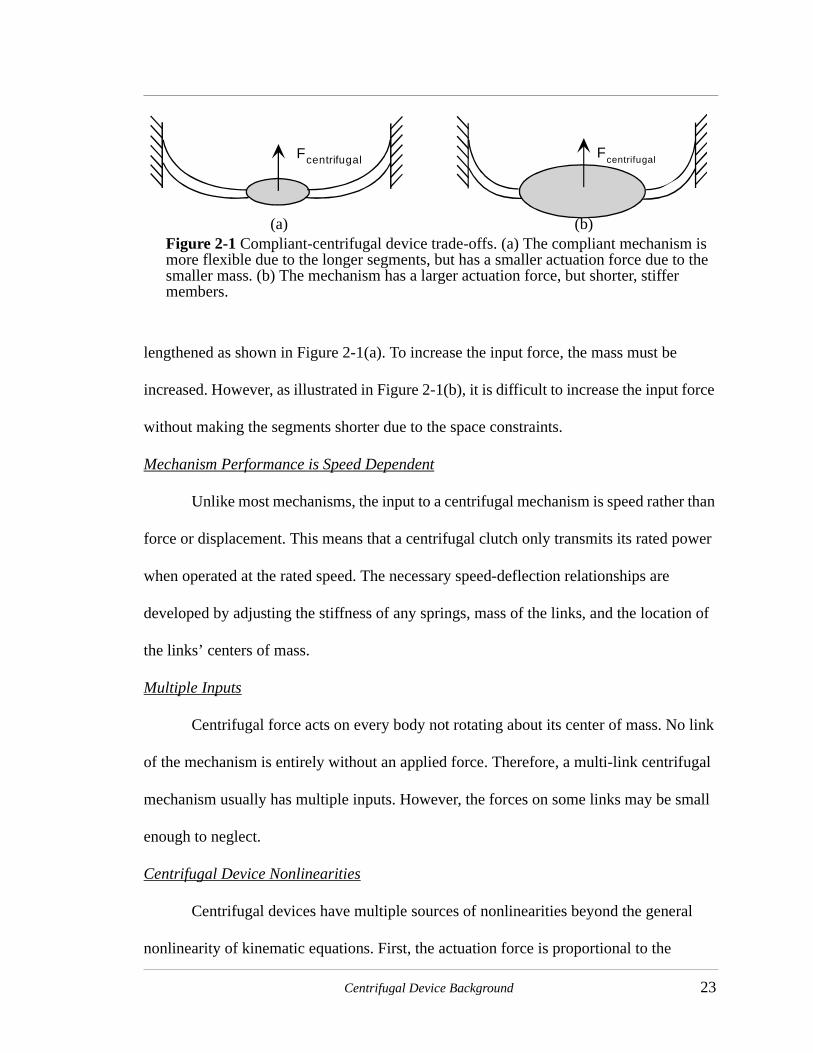
Centrifugal Device Background 23
lengthened as shown in Figure 2-1(a). To increase the input force, the mass must be
increased. However, as illustrated in Figure 2-1(b), it is difficult to increase the input force
without making the segments shorter due to the space constraints.
Mechanism Performance is Speed Dependent
Unlike most mechanisms, the input to a centrifugal mechanism is speed rather than
force or displacement. This means that a centrifugal clutch only transmits its rated power
when operated at the rated speed. The necessary speed-deflection relationships are
developed by adjusting the stiffness of any springs, mass of the links, and the location of
the links’ centers of mass.
Multiple Inputs
Centrifugal force acts on every body not rotating about its center of mass. No link
of the mechanism is entirely without an applied force. Therefore, a multi-link centrifugal
mechanism usually has multiple inputs. However, the forces on some links may be small
enough to neglect.
Centrifugal Device Nonlinearities
Centrifugal devices have multiple sources of nonlinearities beyond the general
nonlinearity of kinematic equations. First, the actuation force is proportional to the
Figure 2-1 Compliant-centrifugal device trade-offs. (a) The compliant mechanism is more flexible due to the longer segments, but has a smaller actuation force due to the smaller mass. (b) The mechanism has a larger actuation force, but shorter, stiffer members.
Fcentrifugal Fcentrifugal
(b)(a)

24 Compliant Centrifugal Clutches: Design, Analysis, and Testing
rotational velocity squared. Second, the force magnitude may change due to changes in
the distance to the center of mass during mechanism operation. Third, the direction of the
force is radially outward from the center of rotation through the center of mass of the
object in question. Therefore, the direction of input force changes as parts of the
mechanism deflect or rotate. For some mechanisms, the deflections are small enough that
the magnitude and direction of the forces can be assumed constant. However, care must be
taken as these assumptions can introduce significant error in some cases.
2.1.2 AdvantagesThe primary advantage of centrifugal devices is their simplicity. They do not
require any external signal or power for actuation or control. They generally use fewer
components than competing solutions. This simplicity leads to lower costs and high
reliability. Often, centrifugal devices are the lowest cost solution to a problem. This cost
difference can be quite significant in some applications. Many years of experience in
designing and using centrifugal devices has permitted steady improvements in their
performance.
Another advantage is their sensitivity to small changes in speed since the actuation
force varies with the speed squared. This sensitivity can be very advantageous in
applications such as centrifugal switches and overspeed brakes. A small increase in speed
can cause a larger increase in actuation force. This helps an overspeed brake stop a larger
than expected load at only slightly higher speeds.
2.1.3 DisadvantagesThe largest disadvantage of centrifugal devices is their lack of versatility.
Centrifugal force is always proportional to the square of the speed. This relationship is set

Centrifugal Device Background 25
by the laws of physics and cannot be modified to meet the needs of a specific application.
Most centrifugal devices are designed or modified for a specific application with specific
operating conditions. They cannot easily be modified to operate under different operating
conditions. By comparison, many electric or magnetically actuated devices can be
precisely controlled for nearly optimal performance under varying conditions.
The lack of flexibility requires that centrifugal devices be custom designed for
many applications. This can increase the cost for applications with unusual requirements.
The expense is reduced by designs that use a series of standard parts with built in
adjustments. This approach reduces the device cost but sacrifices some performance since
the standard parts won’t provide optimal performance for every situation.
The nonlinearities of the actuation and the coupling of geometry and kinematics
discussed earlier are also challenges. Many designs have been developed as much by
testing and intuition as by engineering design.
2.2 Types of Centrifugal Clutches
Centrifugal clutches are actuated by the centrifugal force resulting from rotating
the clutch. They transfer torque through frictional contact, but there are different methods
for transmitting their power and controlling their engagement. Goodling (1974) reviewed
seven basic clutch types, their characteristics, capabilities, limitations, and typical
horsepower ratings. A brief review of that discussion is provided.
2.2.1 Flexible Trailing ShoeThis clutch type has a flexible band lined with friction material that is pulled
around by its leading edge (Figure 2-2). The flexible band is weighted appropriately by

26 Compliant Centrifugal Clutches: Design, Analysis, and Testing
laminations so that the band is pushed out into contact with the clutch drum as the clutch
accelerates. This clutch type is less sensitive to changes in the coefficient of friction than
most types (Goodling, 1977). It is used in applications requiring between ten to two-
thousand horsepower. The clutch band mounting can be modified so that it is reversible.
2.2.2 Connected ShoesThis clutch is perhaps the most common centrifugal clutch type (Figure 2-3). The
friction shoes are held by a rotating link. This link can be equipped with a spring to delay
engagement if required for the application. These clutches have different torque transfer
characteristics depending on the direction of rotation. When rotating so that the friction
force tends to increase the pressure of the shoes on the drum, the torque transfer can be
two to three times as high as in the opposite direction (Dekhanov & Makhtinger, 1987).
The high torque direction is referred to as the aggressive or self-energizing mode. The
Figure 2-2 Flexible Trailing Shoe Centrifugal Clutch. The weighted steel band deflects to contact the drum as the clutch accelerates. The clutch torque output is less sensitive to changes in the coefficient of friction than are most types.
Drum Friction Lining
Steel Band
Driving Lug
Input Hub
ω
Laminations

Centrifugal Device Background 27
lower torque direction is the non-aggressive mode. The aggressive mode sacrifices
considerable smoothness of engagement for the increase in torque transfer achieved.
Connected shoe clutches commonly transfer one to two-thousand horsepower.
Figure 2-3 Connected Shoe Centrifugal Clutch. The arrow indicates non-aggressive rotation direction.
ωClutch Drum
Driving Shaft
OptionalSpringLocation
Shoe Hub

28 Compliant Centrifugal Clutches: Design, Analysis, and Testing
2.2.3 Floating ShoesFloating shoe clutches (Figure 2-4) contain large wedge-shaped shoes which slide
on lugs that project radially outward from the clutch hub. The shoes slide radially outward
to contact the clutch drum. A garter spring may be used to increase the speed of
engagement. These clutches are very simple and yet they maximize the frictional contact
area and centrifugal force for a given volume. These clutches operate the same in both
directions. Horsepower ratings from one half to four thousand are common.
2.2.4 Oil ClutchThe oil clutch (Figure 2-5) is distinguished from most of the other clutch types. Its
distinguishing feature is the inclusion of a capacitance effect that slows down the time
response of the clutch’s output torque to a change in the input speed. Oil clutch torque
output is a function of speed and time. This can significantly increase the starting
smoothness of the clutch.
Figure 2-4 Floating Shoe Centrifugal Clutch.
Drum
Garter Spring
Friction Lining
Shoe
Input Hub
Lug
Centrifugal Device Background 29
Oil clutches operate by means of a flyweight that forces oil through a needle valve
into a variable volume chamber. The oil flow controls the pressure of the friction shoes
against the clutch drum. The volume of the chamber and the orifice size in the needle
valve control the torque transferred and the engagement speed respectively. This is
probably the most adjustable of the clutch types. They transmit from one to three-hundred
and seventy horsepower.
2.2.5 Mercury ClutchMercury clutches (Figure 2-6) also have the advantage of a capacitance effect that
slows the torque response to speed changes. This effect is achieved by the flow of mercury
through a small orifice from a reservoir to an expandable shoe. The shoe is restrained by a
spring to further retard engagement.
The orifice size and spring stiffness control the engagement characteristics, but
their effects can be considered separately. The shoes will respond immediately to speed
input much like a floating shoe clutch. However, the mercury will move through the
Figure 2-5 Oil Centrifugal Clutch. (Goodling, 1974)

30 Compliant Centrifugal Clutches: Design, Analysis, and Testing
orifice over time and slowly increase the torque transfer. The relative mass of the shoes
and mercury determine the relative significance of these two effects. Mercury clutches are
capable or transmitting from fractional to seventy-five horsepower.
2.2.6 Ball & Cone ClutchBall and Cone clutches (Figure 2-7) contain an input member rotating inside of an
oil-filled output housing. The torque is transferred as steel balls are forced outward by the
centrifugal force and in turn push tapered rings against an angled contact surface. The oil
surrounds the mechanism and reduces the heating and wear at the friction surfaces. These
clutches transmit two- to nine-thousand horsepower at operating speeds.
2.2.7 Dry FluidDry fluid clutches (Figure 2-8) have a rotor on the output member that spins in a
housing connected to the input member. The void between the rotor and the housing is
partially filled with small steel shot (0.011” to 0.017” in diameter); the amount of shot
Figure 2-6 Mercury Centrifugal Clutch. The mercury flows from the reservoir to the expandable shoe to help force the shoe against the drum.
Shoe Drum
Input
MercurySpring
At Rest At Rated Speed
Friction
Shoe
Needle Valve

Centrifugal Device Background 31
determines the torque transferred. The centrifugal force packs the shot into the area
between the rotor and the housing to transmit torque. The shot forms a static mass with no
slipping once the load is accelerated. An advantage of this concept is that the primary wear
OutputHousing
Bronze Rings
Centrifugal Balls
Input Shaft
Oil Reservoir
Input CouplingAssembly
Figure 2-7 Ball & Cone Centrifugal Clutch. The Centrifugal balls cam the bronze rings outward to transmit torque through friction with the output housing. (Goodling, 1974)
Figure 2-8 Dry Fluid Centrifugal Clutch. At rated speed, the steel shot packs between the rotor and the output housing to transmit torque.
Output Hub
InputHousing
Steel Shot
Rotor
At Rest At Rated Speed

32 Compliant Centrifugal Clutches: Design, Analysis, and Testing
point of the clutch is the shot which is easily replaced. Dry fluid clutches commonly
transmit between one quarter and four-hundred horsepower.
2.3 Two Evaluation Types
The establishment and use of clear evaluation criteria is an effective way to
compare different options. The use of such criteria help assure that important issues are
systematically considered and provide a natural process for documenting design decisions.
When used well, they can also help identify specific weaknesses and/or strengths of
concepts. Once recognized, the strengths of different approaches may be combined or
weaknesses mitigated.
Roach et al. (1999) and Berglund (1998) proposed similar sets of criteria for
evaluating the compliance potential of rigid-body mechanism designs. Berglund also
developed a set of criteria for comparing different compliant designs and assessing their
value relative to an existing rigid-body design. The criteria translate the common
advantages and disadvantages of compliant mechanisms into a series of gauges for
measuring a concept’s potential.
This work will include two types of evaluations. They are as follows:
• Compliance Potential - Assess the potential for improving the performance of an existing rigid-body mechanism by using a compliant mechanism
• Compliant Concept Comparison - Compare different compliant concepts for the same mechanism type to identify the most promising alternative.
The rigid-body designs will be reviewed using a compliance potential evaluation. Later, a
compliant concept comparison will be conducted to select the best design(s) for further
consideration.

Centrifugal Device Background 33
2.4 Compliance Potential Evaluation
Berglund applied his compliance potential criteria to the seven centrifugal clutch
types described above. His evaluation was used for selecting the clutch types with the
highest potential benefit from the application of compliant mechanism theory.
He divided the clutch evaluation into two phases. The feasibility phase, composed
of the first five criteria, indicates whether a compliant version of a rigid-body mechanism
is possible. If selection criteria one and five or three, four, and five are negative then a
compliant mechanism is not possible. The screening phase, selection criteria six through
eleven, assesses the potential benefits of applying compliant mechanism technology to
rigid-body designs. In each phase, a mechanism is given a “+1” for a “yes” answer, and a
“-1” for a “no” answer. The scores of each mechanism are tallied. The mechanisms with
the highest scores have the greatest compliance potential.
2.4.1 Evaluation ResultsThe results of Berglund’s clutch type evaluation are shown in Table 2-1. The
evaluation indicates that the connected shoe and the floating shoe clutches have the
greatest compliance potential. The flexible shoe clutch shows significant potential as well.
Compliant concepts based on these three clutch types were developed.
2.4.2 Discussion of Most Promising Clutch TypesThe floating and connected shoe clutches scored highest. However, the floating
clutch does not have any components that rotate relative to one another. They move on
linear paths extending radially from the axis of rotation. On a positive note, the clutch uses
springs that can be replaced by compliance to reduce the design complexity and part
count.

34 Compliant Centrifugal Clutches: Design, Analysis, and Testing
The connected shoe clutch appears to be the most promising design. It has
kinematic pairs which do not go through a complete revolution and they are often
produced with springs. They are also used in lower power rating applications where the
potential cost reduction of compliant mechanisms could be a significant advantage.
The flexible shoe clutch also shows promise. Of particular interest is the low
sensitivity to coefficient of friction of its torque output. Goodling (1977) reported that a
31% difference in coefficient of friction might result in a torque output change of 6%.
TABLE 2-1 Compliance Criteria Evaluation of Centrifugal Clutch Types (Berglund, 1998)
Selection CriteriaFlexible
ShoeConnected
ShoeFloating
ShoeMercury Oil
Ball and Cone
Dry Fluid
1. Do revolute joints exist? Yes Yes Yes Yes Yes Yes Yes
2. Is the relative motion in each joint necessary?
Yes Yes Yes Yes Yes Yes Yes
3. Does a revolue joint exist with >360 motion?
Yes Yes Yes No No No No
4. Can some motion > 360 be reduced?
No No No No No No No
5. Do springs exist in design?
No Yes Yes Yes Yes No No
6. Will part count be reduced by compliance?
Yes Yes Yes No No No No
7. Will the weight be reduced by compliance?
Yes Yes Yes No No Yes No
8. Do no links cross? Yes Yes Yes Yes Yes Yes Yes
9. Are any links free from compressive stress?
Yes Yes Yes Yes Yes Yes Yes
10. Are links subject to torque normal to axis of rotation?
Yes Yes Yes Yes Yes Yes Yes
11. Are any links free from prolonged stress or high temperature?
No No No No No No No
TOTAL 5 7 7 1 1 1 -1

Centrifugal Device Background 35
Torque output from a connected shoe or floating shoe clutch would change 31% under the
same conditions. In reality, it is already a compliant design since its performance is
dependent on the deflection of the flexible shoes. Its performance might be increased or its
cost decreased by further application of compliant mechanism theory.
The oil and mercury clutches did not score well on their compliance potential.
However, they have a significant advantage over the other clutch types. In both types,
fluid flow through an orifice controls the torque application. This flow takes a finite
amount of time that slows the clutch engagement and increases the starting smoothness.
Any compliant clutches that could achieve a similar effect would have a significant
performance advantage over other centrifugal clutch types.

36 Compliant Centrifugal Clutches: Design, Analysis, and Testing

37
CHAPTER 3 Centrifugal Clutch Evaluation Procedures and Criteria
One purpose of this work was to systematically apply the techniques of compliant
mechanism design to centrifugal clutches, and assess the relative merits of different
concepts. This chapter describes the systematic procedures used for developing, and
evaluating the different clutches. First, the overall process is outlined. Second, the
evaluation criteria and the procedure used for their application are presented. Finally, this
chapter documents the apparatus and methods used for physical testing of the concepts.
This discussion of methods lays the foundation for all of the work found in the later
chapters.
3.1 Clutch Evaluation Procedure
Develop a PRBM of the concept. The clutches were modeled using the PRBM. The
PRBM generally predicts accurately the performance characteristics of the clutches.
However, even when the model is not accurate quantitatively, it does help the designer
better understand the behavior of the clutch and how it might be improved. The PRBM’s
of the clutches are included in Chapter 4.

38 Compliant Centrifugal Clutches: Design, Analysis, and Testing
Prototype the clutch concept. All of the clutch concepts were prototyped from sheets of
polypropylene 1/4” thick using a numerically controlled (NC) mill. The clutches were
made to a standard outer diameter of 4.40 inches and designed to fit a standard test mount
and drum. In most cases, multiple prototypes were made of the clutch concepts. Although
it is unlikely that the optimal design of a particular clutch was obtained, these different
designs permitted quick exploration of the concept design space and an indication of the
concepts’ potential performance.
Measure the Clutch’s Torque vs. Speed Relationship. This is the single most important
factor in evaluating the clutch concepts. Multiple measurements of the torque-speed
measurements were made of each working prototype. The results of these tests are
documented in Chapter 4. The test methods employed are discussed in “Clutch Testing”
on page 49.
Measure the Concept against the Evaluation Criteria. After modeling and testing the
clutches, the clutches were measured against the established design criteria. The combined
experience of modeling, prototyping, and testing the clutches provide an adequate
experience base for evaluating the potential of each concept.
3.2 Evaluation Criteria
3.2.1 Berglund Criteria Berglund (1998) proposed criteria for evaluating the relative value of different
compliant mechanism designs. Berglund suggested measuring compliant mechanism
designs using these criteria by assigning numbers from 0 to 4 corresponding with a
qualitative assessment of the criteria. The scores for the different criteria are then

Centrifugal Clutch Evaluation Procedures and Criteria 39
weighted and summed. The mechanisms with the highest scores have the greatest
promise.
Berglund suggested fifteen criteria for comparing specific compliant designs.
Since this work focuses on evaluating broad concepts, definite answers are not available
for many of the criteria that Berglund proposed. His criteria are better suited to evaluating
specific designs for specific applications. Therefore, Berglund’s criteria are not used
directly in evaluating the compliant centrifugal clutch concepts. Instead, the criteria he
suggested are combined with several other criteria specific to centrifugal clutches.
3.2.2 Criteria Adapted from Berglund for Use in this WorkThe following criteria are adapted from Berglund’s work for evaluating the
compliant centrifugal clutch concepts.
Suitability of Loading
The loading on compliant mechanisms is important for two reasons. First, the
deflection path of the mechanism depends on the loading applied. Second, the life of the
mechanism depends on the applied stresses. The flexible compliant segments are much
more susceptible to fatigue failures than are rigid links. Experience has shown that
compliant mechanisms can be designed with adequate fatigue life, but careful
consideration of loading is necessary.
Berglund identified four guidelines for evaluating the suitability of loading for
flexible segments. For this work, they are evaluated individually so that no factor is
overlooked and then combined into one overall factor. The guidelines are:

40 Compliant Centrifugal Clutches: Design, Analysis, and Testing
• Minimal compression in the long, thin flexible segments.
Long, thin flexible segments are prone to buckling under compressive loads. Buckling should generally be avoided since it is a somewhat unpredictable phe-nomena, is not accounted for in the PRBM, and may fracture or plastically deform the flexible member.
• Small deflection required in flexible segments.
Smaller deflections mean the stresses are lower in the flexible segments and the PRBM is most accurate.
• Minimal Tension in the flexible members.
Most mechanisms must go through a particular path and whatever force neces-sary to achieve the necessary rotation or displacement is applied. Tensile forces oppose the deflection of flexible members. When they are present larger input forces and thus larger stresses are required.
• Passive joints used instead of rigid-body links in links that require compressive loads.
Passive joints are cams that act like pin joints but can only receive compressive forces. Passive joints can support large loads through rigid segments without the extra parts and complexity of a pin joint. They should be considered for use in any joints with continual compressive loading.
Ease of manufacture
One of the primary advantages of compliant mechanisms is reduced production
cost. The relative reduction in manufacturing costs of different compliant mechanisms is
an important consideration. However, manufacturing costs are difficult to estimate
without making some simplifications. Since the clutch concepts are planar, all of them
could be manufactured by a cutting process, and in fact, many compliant clutches are
currently produced from flat stock by cutting operations such as laser cutting. If a cutting
process is used, the relative costs of different clutches should be proportional to the length
of the perimeter of the clutch’s profile. The smaller the profile perimeter, the quicker and
less expensive the clutch can be manufactured.

Centrifugal Clutch Evaluation Procedures and Criteria 41
Therefore, the total perimeter length of the clutches is used as an index of relative
manufacturability. The perimeter was measured from the CAD package used to model the
prototypes for manufacturing.
Retention of resilience in compliant members
In many clutch applications, the clutch must not transmit torque when the input
speed is below a certain level. To prevent torque transfer at slower speeds, the clutch must
have springs to resist the centrifugal force without transmitting torque. If the stiffness of
the springs changes significantly with time or with normal fluctuations of the operating
environment, the clutch will not perform reliably.
The ability of the springs to retain their resilience is dependent on a variety of
factors. These factors include the operating temperature, the chemical environment, the
stress level in the segments, and how long stress is applied. Many of these factors such as
the operating environment are primarily determined by the application rather the
mechanism’s design. Moreover, the significance of all of these effects is profoundly
dependent on the material used. Since the material selection and particular application
environments are outside the scope of this work, the influence of these factors on the
resilience of the compliant members will not be considered in the evaluation.
This factor will be assessed qualitatively by considering the relative stress level of
the flexible segments and the sensitivity of the clutch performance to changes in the
resilience of the compliant members.
3.2.3 Additional Criteria for Centrifugal ClutchesThe most important factors in clutch performance are torque transmission
capacity, engagement speed, and smoothness of start. Once these concerns are addressed,

42 Compliant Centrifugal Clutches: Design, Analysis, and Testing
the performance after wear, the wear life, and clutch heating during start-up are the other
major concerns to be considered. In specific applications, reversible operation, torque
limiting performance under overspeed conditions, or torque output sensitivity to the
coefficient of friction may also be important. Since the overall concepts are being
evaluated and not the suitability of the concepts for a specific application, these criteria
will be simplified in the work.
Torque Capacity
In small power, low cost applications, the torque capacity is the single most
important factor. Torque capacity is determined by four parameters: the mass of the arms,
the mechanical advantage of the resulting centrifugal force, the stiffness of any springs,
and the driving speed. Since the position of most clutch types is constant after contact, the
mechanical advantage is constant. Therefore, the four factors can be reduced to three by
combining the mass and mechanical advantage factors to create a single torque factor. In
many clutch designs, an analytical determination of these parameters is unwieldy, but they
can be determined quite readily from experimental data. If the actuation mass is
maximized while maintaining a uniform size constraint, the torque factor can be used as
an index of the absolute torque capacity of the clutch type. Since all of the clutches fit
within the same space, a clutch with a higher torque capacity rating can be made more
compactly than clutches with lower torque ratings for a given set of application
requirements.
Multiple definitions of the three parameters are possible. For this work, the
equation reported by St. John (1979) will be used. It is

Centrifugal Clutch Evaluation Procedures and Criteria 43
(3.1)
where,
= basic clutch torque, torque output at 1000 rpm without any springs
= operating torque of the clutch at speed
= the operating rpm/1000
= the engagement rpm/1000
Equation (3.1) is valid for speeds greater than . Below , the equation predicts nega-
tive torque transfer which is not possible. The parameters in Equation (3.1) were deter-
mined from the experimental data. The equation was solved for to get
(3.2)
This equation was applied to each data point using the measured speed and torque for
and respectively. The value of was selected as that value which minimized the stan-
dard deviation of the values calculated from the different data points. The values
generally match the observed engagement speed.
The parameter is a helpful concept because it facilitates comparison between
clutches with different engagement and operating speeds. In order to meaningfully
compare torque outputs, the engagement and test speed of every clutch would have to be
identical. The use of a common size envelope for all of the designs, further normalizes the
values with respect to clutch size to provide a more equal measure of relative torque
capacity.
T Tb Uo2
Ur2
–( )=
TbT UoUoUr
Ur Ur
Tb
TbT
Uo2
Ur2
–( )-----------------------------=
Uo
T Ur
Tb Ur
Tb
Tb

44 Compliant Centrifugal Clutches: Design, Analysis, and Testing
For most of the clutches, applying Equation (3.1) with the parameter values
determined as explained above fit the experimental data quite well. However, this
equation is of the form
(3.3)
It neglects any effects that vary linearly with rotational velocity. Some clutches have
significant linear terms that cannot be ignored. This equation is not a good fit for these
clutch types. The two clutch types affected are the split arm clutches with less-stiff
segments and the grounded opposing arm clutches. Figure 3-1 compares the adequacy of
the model predictions for a typical clutch and one with a significant linear term.
The linear terms in both of these clutches are likely due to members that continue
deflecting with increasing speed and torque even after contact. In the split arm clutch,
these deflecting members are non-contacting flexible segments. In the grounded opposing
arm clutches, the flexible members connected to the inner hub continue deflecting. The
significance of the linear terms will depend on the stiffness of the flexible segments.
Starting Smoothness
In some applications starting smoothness is not critical, but generally clutches with
smoother starting capability are preferred. The starting smoothness is a function of load
inertia, the speed-torque relationship of the driver, and the speed-torque capability of the
clutch. The clutch’s effect on starting smoothness can be seen by fixing the other two
variables. All remaining differences in load acceleration are due to the clutch.
Virtually all centrifugal clutches have a quadratic relationship between output
torque and input speed. The only exceptions are those clutches that are dependent on fluid
T aω2 c+=
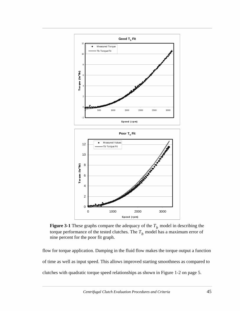
Centrifugal Clutch Evaluation Procedures and Criteria 45
flow for torque application. Damping in the fluid flow makes the torque output a function
of time as well as input speed. This allows improved starting smoothness as compared to
clutches with quadratic torque speed relationships as shown in Figure 1-2 on page 5.
Good Tb Fit
-2
0
2
4
6
8
10
12
0 500 1000 1500 2000 2500 3000
Speed ( rp m)
M easured Torque
Tb Torque Fit
Poor Tb Fit
0
2
4
6
8
10
12
0 1000 2000 3000
Speed ( rp m)
M easured Values
Tb Torque Fit
Figure 3-1 These graphs compare the adequacy of the model in describing the torque performance of the tested clutches. The model has a maximum error of nine percent for the poor fit graph.
TbTb

46 Compliant Centrifugal Clutches: Design, Analysis, and Testing
All quadratic relationship clutches that fit Equation (3.1) will have the exact same
starting smoothness if designed for the same application. However, clutches that are not
adequately approximated by Equation (3.1) will vary from the norm. The basic application
requirements specify the operating torque at the required operating speed and the
engagement speed where torque is zero. Additionally, the equation for the clutch torque
model has its minimum when the speed is zero. These three pieces of information,
operating speed and torque, engagement speed, and a zero linear term, completely define
the speed-torque relationship.
The load acceleration is a function of the load inertia and the torque-speed
relationships of the driver and the clutch. For a given load and driver, the load acceleration
is directly related to the torque-speed characteristics of the clutch. Therefore, all clutches
with the same torque-speed relationship will have the same starting smoothness for a
given application.
However, if a linear term is added to the model, the application requirements do
not completely define the clutch torque characteristics. This may allow the clutch to be
tuned for improved starting smoothness within the given application constraints, but the
amount of variation possible is limited because the starting smoothness and the
engagement speed are primarily determined by one design variable: the stiffness of the
flexible members. Since the variables are coupled, the potential variation in the starting
smoothness of the clutches with linear terms is limited.
Since all of the concepts have relatively small linear torque terms and the linear
terms are not independent of engagement speed, there is no appreciable variation in

Centrifugal Clutch Evaluation Procedures and Criteria 47
starting smoothness between the tested clutch concepts. Therefore, this parameter is not
used in the concept evaluation
Wear Performance
Most well-designed clutches will fail or require service due to excessive wear.
Several factors indicate clutch performance under wear conditions. First is contact area.
Increasing the contact area with the drum improves the clutch wear characteristics. Second
is the sensitivity of clutch torque output to wear. Three reasons a clutch might be sensitive
to wear are:
• compliant segments are wear points• torque is sensitive to the amount of rotation for engagement• torque is sensitive to the exact contact location
The effects of wear include significant changes in transmitted torque, engagement speed,
or operating stresses in the flexible segments.
Other Performance Advantages
Many other clutch features are useful in specific applications or groups of
applications. Some of these attributes are bi-directional operation, decreased torque
sensitivity to the coefficient of friction, and reduced torque output above the operating
speed. These advantages are valuable in some applications and are of little importance in
others.
To consider these characteristics in this general evaluation, they will be grouped
together into one category. The default clutch evaluation with respect to this criteria will
be zero. The clutch’s score can then be raised by one point for each extra feature
incorporated into the design.

48 Compliant Centrifugal Clutches: Design, Analysis, and Testing
3.2.4 Clutch Rating MethodsExcept as noted under “Other Performance Advantages” the clutch will be rated
from 0 to 4 with respect to each criteria. The meaning of the ratings is given in Table 3-1.
These ratings are multiplied by a weighting factor between one and five that reflects the
importance of the particular criteria. Larger values of the weighting factor indicate more
vital criteria. All of these values will be summed for a particular clutch to reach an overall
clutch score. Higher scores indicate greater concept potential.
The weights were selected to reflect the relative importance of the criteria for the
types of applications that compliant centrifugal clutches would be best suited. These
applications would probably be low cost consumer items that aren’t expected to have an
extended life. Therefore, the manufacturability was weighted highest with a five. The
torque capacity was rated a four since it directly affects the size, weight, and material costs
of a clutch. Wear was a three since every clutch must withstand a minimum wear time.
Retaining resilience was weighted as a two since loss of resilience might degrade
performance but would not cause failure. Similarly Loading was ranked a two since the
expected applications do not require indefinite life, and most of the concepts can be
TABLE 3-1 Definition of Clutch Ratings
Rating Definition Rating
Unacceptable 0
Below Average 1
Average 2
Better than Average 3
Superior Performance 4

Centrifugal Clutch Evaluation Procedures and Criteria 49
modified to improve the loading if necessary. Other Performance Parameters is weighted
as a one since few low cost applications need any of the extra parameters.
3.3 Clutch Testing
3.3.1 Test SetupThe most fundamental performance metric of the centrifugal clutches is torque
transfer at a given speed. The torque was measured by connecting a cylindrical drum to a
fixed torque gauge while a clutch rotated inside of the drum. A driving source was
selected with much higher power output than the clutch. This makes the torque
measurement simple, but introduces an additional problem. Throughout a test, the clutch
is dissipating its maximum power capacity through friction at the clutch-drum interface.
Plastic at the contact point quickly melts when polypropylene clutches are tested without a
friction material on the contact surfaces. This results in viscous rather than coulomb
energy dissipation at the contact surfaces.
This problem was resolved by adhering cotton webbing to the contact areas on
each polypropylene clutch as shown in Figure 3-2. The webbing provided a consistent
friction surface and insulated the plastic clutch from the heat generated during testing.
Further, the clutch rubs against a large steel drum that provides an excellent heat sink.
Together, the webbing and drum reduced heating in the clutch enough that temperature
dependence of the plastic material properties could be disregarded. Temperatures in the
clutch did not change noticeably even after several minutes of continuous operation.
The coefficient of friction between the cotton webbing and the steel drum was
measured as shown in Figure 3-3. An adjustable inclined plane was made from steel with

50 Compliant Centrifugal Clutches: Design, Analysis, and Testing
a similar surface finish as the clutch drum. The weight lined with cotton webbing was
placed on the inclined plane. The angle of the inclined plane was adjusted until the weight
would slide down the incline plane at a steady rate (no acceleration). This permitted
measurement of the sliding coefficient of friction rather than the static coefficient of
friction. To achieve steady sliding, the weight was bumped to overcome the static friction
and initiate sliding.
Figure 3-2 A compliant centrifugal clutch with cotton webbing glued on the contact surface.
Figure 3-3 Measuring the coefficient of friction.
x
y
Ff=µFN
FN= mg cosθ
mg
θθ
Ff= mg sinθ

Centrifugal Clutch Evaluation Procedures and Criteria 51
The coefficient of friction (µ) is then found by summing the forces and applying
the relationship
(3.4)
Summing the forces on the sliding block and solving for the normal and frictional forces
gives
(3.5)
(3.6)
Equation (3.5) and (3.6) are substituted into Equation (3.4) and solved for to find
(3.7)
which can also be expressed as
(3.8)
The clutches were tested on a lathe with continuous speed variation as shown in
Figure 3-4. The clutches were rotated inside the fixed steel drum while the torque transfer
and driving speed were measured using computer data acquisition. The drum is mounted
on the driving shaft with bearings and restrained from rotation by the torque gauge.
APPENDIX B “Experiment Data” contains further data about the test setup and
instrumentation.
Ff µFN=
FN mg θcos=
Ff mg θsin=
µ
µ θsinθcos
------------ θtan= =
µ yx--=

52 Compliant Centrifugal Clutches: Design, Analysis, and Testing
Figure 3-4 (a,b) Clutch test setup. (a,c) The tachometer measures the clutch speed. (a,d) The clutch spins inside the stationary clutch drum. (a,d) The output torque is measured be the reaction torque gauge mounted between the tailstock and the clutch drum. The clutch drum is mounted on the driving shaft with bearings.
Lathe
Tachometer
Tailstock
Drum
Driving Shaft
Torque Gauge
Clutch
Bearings
(a)
(b)
(c) (d)
clutch
torquegauge
tailstock
drum
lathe
computer
flexiblecoupling
tachometer

Centrifugal Clutch Evaluation Procedures and Criteria 53
3.3.2 Test ProceduresThe torque gauge measures the torque output from the clutch plus the torque due to
friction in the bearings. To account for this error, the torque on the drum due to the bearing
friction was measured. A linear fit to the bearing torque data was then subtracted from the
measured torque values to find the clutch torque output. “Bearing Torques” on page 135 in
APPENDIX B contains more information. Each clutch was cycled through the speed
range of the lathe two to three times. The data sets from the different cycles were
compared to verify that the results were consistent. Each data point is the average of ten
readings. No additional filtering was performed on the torque sensor output. The
tachometer signal was filtered by a capacitor connected in parallel with the output voltage.
Reference “Tachometer” on page 134 for more information. The data was sampled at ten
hertz and the data points were recorded in a file for review after the test. Figure 3-5 shows
a sample data set from a clutch test. APPENDIX B “Experiment Data” contains
representative data sets for each clutch prototype.
3.3.3 Error SourcesEvery test setup has error sources and it is important to understand what these
sources are and how they impact the accuracy of the measured data. The errors in the
measurements are discussed and their relative magnitudes are mentioned.
Coefficient of Friction
The coefficient of friction directly affects the torque capacity of all of the clutches.
However, the coefficient of friction is subject to many variables even under controlled
conditions. Dirt or grease contamination on either of the contacting surfaces would have a

54 Compliant Centrifugal Clutches: Design, Analysis, and Testing
noticeable impact on the torque capacity. The torque error due to the accuracy of the
measured coefficient of friction could be ten to fifteen percent.
Cotton Webbing Thickness
The cotton webbing has an irregular surface due to the coarse weave, and easily
compresses several thousandths of an inch. This makes it very difficult to define the
effective outer radius of the clutch. The webbing is also attached with a layer of glue that
may vary in thickness. Considering that the total deflection of most of the clutches is only
0.050 inches, a variation of only several thousandths of an inch may cause noticeable error
in the engagement speed
Modulus of Elasticity
The modulus of elasticity of the flexible segments directly affects their effective
spring constant. The effective modulus of elasticity is subject to variation due to
Sample Clutch Test Data
-1
1
3
5
7
9
11
0 500 1000 1500 2000 2500 3000
Rotational Velocity (RPM)
To
rqu
e (i
n*l
b)
Figure 3-5 Test data from a representative clutch torque test.

Centrifugal Clutch Evaluation Procedures and Criteria 55
production, light exposure, stress cycling, and exposure to some chemicals. The stress
relaxation of the polypropylene is very significant. Cragun, et al. (1998) measured the
modulus of elasticity of polypropylene when stressed to half of the yield stress. They
measured an initial values of 165 ksi dropping off to a value of about 120 ksi after several
minutes. This degree of stress relaxation makes predicting the engagement speed in
polypropylene very difficult. This is a significant error source in the engagement speed.
Density
The density of polymers can vary between manufacturers and between batches.
Density influences both torque capacity and engagement speed. However, this variation
and the error it introduces are probably small.
Machining Tolerances
Most numerically controlled machines are accurate to within several thousandths
of an inch. That error would not have a noticeable impact on the torque capacity, but it
would affect the engagement speed significantly. Many flexible segments are only 0.050
to 0.075 inches thick. An error of 0.002 inches on both sides of the segment could
decrease the spring constant by fifteen to twenty-two percent. The spring constant is very
sensitive to the segment thickness because it is proportional to the thickness cubed.
Electrical Noise
The signal from the torque transducer was amplified by 532 times by an analog
circuit before it was sampled by the computer. This amplification also amplifies the noise.
This problem was mitigated by averaging ten readings for every stored value, and only
testing clutches when no other machines were running adjacent to the test lathe. Figure 3-
5 shows that the random error is small relative to the magnitude of the measured signals.

56 Compliant Centrifugal Clutches: Design, Analysis, and Testing

57
CHAPTER 4 Compliant Centrifugal Clutch Designs
In order to develop new clutch configurations, rigid-body replacement synthesis
was applied to the connected shoe, floating shoe, and flexible trailing shoe centrifugal
clutches. Modifying these designs and developing original designs from basic mechanism
classes such as the slider-crank yielded additional clutch concepts.
The generated concepts comprise four novel compliant centrifugal clutch types.
Two of the types are compliant floating-shoe clutches. One type is a flexible trailing shoe,
and the other is based on a double-slider mechanism. Two existing compliant versions of
the connected shoe clutch are also presented.
The new clutch concepts and two existing clutch designs are described and
concept testing results are reported. Further test data is reported in APPENDIX B. The
clutch types are evaluated using the method presented in Chapter 3 to identify those with
the greatest potential.

58 Compliant Centrifugal Clutches: Design, Analysis, and Testing
4.1 Existing Compliant Designs
Two compliant centrifugal clutch concepts are currently manufactured and used
for a variety of applications: the conventional compliant centrifugal clutch and the S-
clutch. These clutches meet the performance requirements in simple applications much
less expensively than competing rigid-body designs. These clutches have been developed
and designed largely by trial and error.
A more effective design model will assist in designing these mechanisms so that
they may be adapted more readily to new applications. A PRBM of the concepts presents
a partial solution to this need. Since much of the model is the same for both clutches, the
conventional compliant centrifugal clutch will be presented in full detail. The S-clutch
will be discussed more briefly, focusing on its dissimilarity to the first clutch.
4.1.1 Conventional Compliant Centrifugal Clutch (C4)
The conventional compliant centrifugal clutch (C4) (Figure 4-1(a)) is already used
in low cost applications such as radio-controlled helicopters which do not demand a
particularly smooth start or precise torque characteristics. These clutches generally
operate at low power ranges characteristic of radio-controlled models and some lawn and
garden equipment. The clutch is easily produced in low volumes because it does not
require significant specialized tooling. Frequently, the clutch is not lined with friction
material to further reduce manufacturing cost.
The PRBM of this design is a connected shoe clutch with a small-length-flexural
pivot as illustrated in Figure 4-1(b). The clutch arm is modeled as though it were pinned to

Compliant Centrifugal Clutch Designs 59
the base of the clutch with a torsional spring to model the energy storage of the flexed
beam connecting the arm to the clutch base. The characteristic pivot is placed at the
thinnest point in the curved beam. The flexible segment is short enough relative to the
length of the arm that the displacement at the end of the flexible segment can be
disregarded while considering only the angular deflection.
The spring constant for the model can be approximated by modeling the curved
segment as several linear beams. The spring constant is often negligible relative to the
other forces when the clutch is analyzed at operating speed. Therefore, a simple
approximation is often sufficient. However, in considering torque near the engagement
speed, a more accurate approximation is essential for model accuracy.
Rbc
Rcm
Rcont
FοFN
FfKΘ∗∆Θ
Rdrumγβ
Redge Rclutch
Rcont
Rclutch(1<γ)
Figure 4-1 (a)Conventional Compliant Centrifugal Clutch in its undeflected and deflected positions, (b) force and distance vectors for torque equations, (c) vectors and angles used in the contact equations.
(a)
(b) (c)

60 Compliant Centrifugal Clutches: Design, Analysis, and Testing
The torque transfer capacity can be estimated by assuming a line of contact on an
appropriate point on the clutch drum. The contact line is normal to the page and so it is a
point on the profile. The forces on the clutch arm can be summed and solved for the
frictional force. Figure 4-1(b) diagrams these forces. The vector summation of moments
about the pin is
(4.1)
where the radial acceleration is treated as an inertial force. By assuming that the frictional
force on the clutch drum is proportional to the normal force, the equation can be expressed
as
(4.2)
where is the friction coefficient and is the unit vector in the direction of . This
equation can be solved for the magnitude of the normal force to find
(4.3)
where
(4.4)
The torque is then given by
(4.5)
K∆Θk Rcm Rbc– )( Fo× Rcont Ff Rcont FN×+×+ + 0=
K∆Θk Rcm Rbc– )( Fo× Rcont FN µffˆ Rcont FN×+×+ + 0=
µ ffˆ Ff
FNK∆Θk Rcm Rbc– )( Fo×+
Rcont– ffˆ µ Rcont fn
ˆ×–×-------------------------------------------------------------=
fnFN
FN
---------=
T FN µRdrumn=
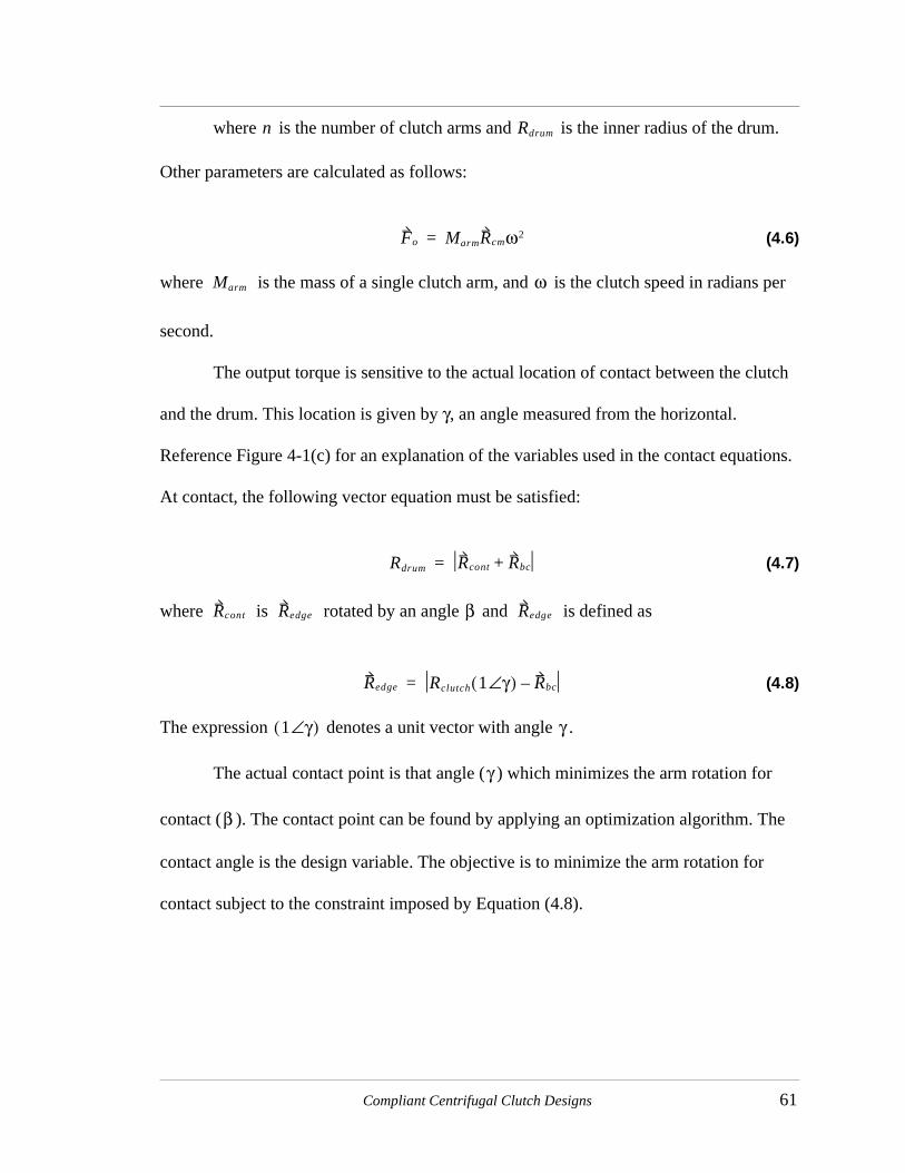
Compliant Centrifugal Clutch Designs 61
where is the number of clutch arms and is the inner radius of the drum.
Other parameters are calculated as follows:
(4.6)
where is the mass of a single clutch arm, and is the clutch speed in radians per
second.
The output torque is sensitive to the actual location of contact between the clutch
and the drum. This location is given by γ, an angle measured from the horizontal.
Reference Figure 4-1(c) for an explanation of the variables used in the contact equations.
At contact, the following vector equation must be satisfied:
(4.7)
where is rotated by an angle and is defined as
(4.8)
The expression denotes a unit vector with angle .
The actual contact point is that angle ( ) which minimizes the arm rotation for
contact ( ). The contact point can be found by applying an optimization algorithm. The
contact angle is the design variable. The objective is to minimize the arm rotation for
contact subject to the constraint imposed by Equation (4.8).
n Rdrum
Fo MarmRcmω2=
Marm ω
Rdrum Rcont Rbc+=
Rcont Redge β Redge
Redge Rclutch 1 γ∠( ) Rbc–=
1 γ∠( ) γ
γ
β

62 Compliant Centrifugal Clutches: Design, Analysis, and Testing
Test Results
Figure 4-2 explains the parameterization of the clutch. Refer to Table 4-1 for the
parameter values for the three prototype C4 clutches with the measured Tb values and the
Figure 4-2 The parameterization of a C4 clutch.
RclutchRdrum
Rhole
θhole
Dhole
Wcut
n = Number of Arms
t
TABLE 4-1 Parameter values for C4 test clutches.
Clutch Parameters C4 #1 C4 #2 C4 #3
Rclutch (in) 2.200 2.200 2.200
Rhole (in) 2.018 1.967 1.977
Dhole (in) 0.185 0.286 0.266
θhole (deg) 36.66ο 28.80ο 31.66ο
Wcut (in) 0.125 0.125 0.125
Rdrum (in) 2.250 2.250 2.250
n 3 2 2
t (in) 0.250 0.250 0.250
µ 0.28 0.28 0.28
Tb (in*lb/1000 rpm) 1.04 1.06 0.83
Perimeter (in) 34.65 29.14 28.71

Compliant Centrifugal Clutch Designs 63
calculated perimeters. The Tb values varied from 0.86 to 1.06 in*lb/1000 rpm. The profile
perimeter varied from 28.7 to 34.7 inches.
4.1.2 S-ClutchThe S-clutch (Figure 4-3) is another compliant version of the connected shoe
clutch. The S-clutch uses longer flexible segments than the C4 clutch. This reduces the
stresses in the flexible segments when the arm deflects to contact the drum. The lower
stress levels make the design more suitable for lower strength materials like powdered
metal. This clutch is used in many low-end gas-powered lawn tools.
The clutch can be modeled in three ways: small deflection beam theory, FEA, and
the PRBM. Small deflection beam theory can be applied with reasonable accuracy since
the space between the clutch and the drum is generally very small. FEA would be the most
accurate method since it can best account for the irregular beam cross section at the ends.
The PRBM aids in visualizing the behavior of the clutch, particularly under large
deflections. An approximate PRBM is presented for reference.
Figure 4-3 An S-clutch. The longer flexible segments help reduce the bending stress relative to a comparable C4 clutch.
Rcm θcm
tfs
lfs

64 Compliant Centrifugal Clutches: Design, Analysis, and Testing
Since the flexible segment is long, the small-length-flexural-pivot model used for
the C4 clutch is not as accurate. However, there is not a general model of a fixed-fixed
segment like this one. The fixed-fixed segment is difficult to model because it is subject to
both force and moment loads as shown in Figure 4-4(b). The closest PRBM types are for
flexible beams loaded either by a force or a moment. An approximate model may be
developed by using a value of the characteristic radius factor ( ) and the stiffness
coefficient ( ) between the values predicted by the force and moment load models
(Appendix A).
Additional error is introduced by the difference between the pseudo-rigid-body
angle (Θ) and the actual angle of the beam tip (θο). This error can be reduced by placing
another pin at the beam tip to accommodate the difference in angle between the two links.
The angle of the final link is given by
θο
Θ M=KΘ∗∆Θ
FfFN
Fcm
PRBM
Links
Figure 4-4 S-clutch analysis. (a) The applied forces on the clutch arm. (b) The applied forces on the flexible segment. A moment is required for equivalence since the forces were moved. (c) The PRBM of the clutch arm. The arm is divided into two segments, one for the rigid segment and one for the flexible segment. However, the angle of the second link (θο) is a function of the angle of the first link (Θ).
(a) (b) (c)
γ
KΘ

Compliant Centrifugal Clutch Designs 65
(4.9)
The parameter is a function of the load type and direction. Approximate values can be
developed for mixed force and moment loading from the models for simple loading types.
Like the C4 clutch, the normal force can be found by summing the moments about
the characteristic pivot at the ground. The normal force can then be used in Equation (4.5)
to predict the torque output.
Test Results
Two S-clutch prototypes were constructed and tested. The parameters of the
prototypes and the measured Tb values are given in Table 4-2, where the parameters are
explained in Figure 4-3. The two prototype clutches are very similar because the simple
geometry leaves little room for adjusting the mechanical advantage of the centrifugal
∆θo ∆Θcθ=
cθ
TABLE 4-2 Parameter values for prototype S-clutches.
Clutch Parameters #1 #2
Rclutch (in) 2.200 2.200
Arm Volume (in3) 0.96 0.95
Rcm(in) 1.338 1.338
θcm (deg) -11.8 -12.3
lfs (in) 1.250 1.455
tfs (in) .2072 1.25
Rdrum (in) 2.250 2.250
n 2 2
t (in) 0.250 0.250
µ 0.28 0.28
Tb (in*lb/1000 rpm) 1.10 1.14
Perimeter (in) 32.56 33.23

66 Compliant Centrifugal Clutches: Design, Analysis, and Testing
actuation force. The only significant variation between the two clutches lies in the
stiffness of the flexible members, but the purpose of the Tb value is to permit torque
capacity comparison of clutches with different effective spring constants. The measured
Tb values of 1.10 and 1.14 in*lb/1000 rpm verifies that the Tb value does compare clutch
torque capacities even when the clutches have different spring stiffnesses. The profile
perimeter values are 32.6 and 33.2 inches. These values are very similar to those from the
C4 clutches.
4.2 Novel Compliant Designs
4.2.1 Floating 1 (F1)This design is a compliant version of the floating shoe clutch. See Figure 4-5. The
design combines the shoes and the spring of a rigid-body floating-shoe clutch to reduce
the part count. The shoes are connected by thin flexible segments that provide the spring
force. However, the hub rather than the flexible segments bears the torque load. This
increases the design space of the concept. The clutch can be designed to engage at very
low speeds using very flexible connecting elements while supporting large torque loads
through a stiff hub. Many competing designs require that the torque loads pass through the
flexible segments. In these cases, torque capacity and engagement speed are not entirely
independent. A disadvantage of the stiff hub is that additional parts may be necessary to
hold the floating shoes on the hub.
The geometry and loading of the clutch are symmetrical. Therefore, the clutch can
be analyzed by considering just one shoe and applying geometric and force constraints
imposed by the symmetry of the closed loop. The force exerted by the hub transfers torque

Compliant Centrifugal Clutch Designs 67
from the driving input to the floating member of the clutch. Before the floating member
contacts the drum, the torque input through the hub overcomes losses such as air
resistance and accelerates the clutch. The hub force is negligible while the clutch is
rotating at a constant speed, it has not contacted the drum, and the center of mass is on the
line that bisects .
T1
l1 l2
FN
Ff
Fo
T2
T1
l1l2
Fo
T2
rs1 rs2
Fhub
rsα
θ2 θ1
FοFlexibleSegment
Shoe
Hub
n = 6 symmetrical segments
Rcm
Ri
Ro
lfs
tfs
ωθcm
Figure 4-5 A F1 type centrifugal clutch. (a) The clutch is pictured with its center hub. (b) The clutch’s PRBM and applied centrifugal forces are shown. (c) The forces on a clutch segment before engagement and (d) after engagement when the center of mass lies on the bisector of .α
(a) (b)
(c) (d)
α
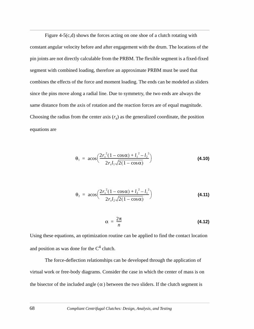
68 Compliant Centrifugal Clutches: Design, Analysis, and Testing
Figure 4-5(c,d) shows the forces acting on one shoe of a clutch rotating with
constant angular velocity before and after engagement with the drum. The locations of the
pin joints are not directly calculable from the PRBM. The flexible segment is a fixed-fixed
segment with combined loading, therefore an approximate PRBM must be used that
combines the effects of the force and moment loading. The ends can be modeled as sliders
since the pins move along a radial line. Due to symmetry, the two ends are always the
same distance from the axis of rotation and the reaction forces are of equal magnitude.
Choosing the radius from the center axis (rs) as the generalized coordinate, the position
equations are
(4.10)
(4.11)
(4.12)
Using these equations, an optimization routine can be applied to find the contact location
and position as was done for the C4 clutch.
The force-deflection relationships can be developed through the application of
virtual work or free-body diagrams. Consider the case in which the center of mass is on
the bisector of the included angle ( ) between the two sliders. If the clutch segment is
θ12rs
2 1 αcos–( ) l12 l2
2–+
2rsl1 2 1 αcos–( )----------------------------------------------------------- acos=
θ22rs
2 1 αcos–( ) l22 l1
2–+
2rsl2 2 1 αcos–( )----------------------------------------------------------- acos=
α 2πn
------=
α

Compliant Centrifugal Clutch Designs 69
oriented so that the vector from the rotational axis to the center of mass is vertical, the
centrifugal force and mechanism position can be related by
(4.13)
(4.14)
(4.15)
(4.16)
These equations are valid when the change in due to the mechanism movement remains
small enough that the resulting change in direction and magnitude of can be neglected.
These equations can be used in two ways. The easiest is to first evaluate the
position relationships of the clutch for a given value of and then apply the known angle
values to Equations (4.13) to (4.16). The direction of is known and its magnitude can
be evaluated directly from Equation (4.13). The equations can also be evaluated when
given a value of to calculate and solve for the resulting mechanism position.
However, this solution is only possible through numerical methods for systems of
nonlinear equations.
A similar approach can be utilized to develop equations for the normal force on the
clutch drum. In this case, the mechanism position can be found from the constraints
imposed by contact with the drum. A new force-deflection analysis is then performed
considering normal, friction, and hub forces. Since the friction force is a known function
0 Fo rcm rs1–( ) j×( ) T+ 1 T21 l1 Fo
πn--- π θ1+( )– sin
α2--- π α
2---–
sin+sin
---------------------------------------------+ +=
Fo mω2rcm=
T1 k1 θ1o θ1–( )=
T21 k21 θ1o θ1–( ) θ2o θ2–( )–[ ]=
rs
Fo
rs
Fo
ω Fo

70 Compliant Centrifugal Clutches: Design, Analysis, and Testing
of the normal force, the normal and friction force are really just one unknown. The
clutch’s torque transfer is given by Equation (4.5).
The clutch acts much like a standard floating clutch except that the radial offset
between connections on each side of the shoes and the bending of the flexible segments
apply a moment to the shoe. Therefore, the shoes rotate as they move radially outward to
contact the drum.
Test Results
The F1 clutches are parameterized as illustrated in Figure 4-5(a). Table 4-1 lists the
parameter values for the F1 prototype tested. The Tb value indicates a significant increase
in torque capacity relative to the C4 and S-clutches. However, the clutch also has a
TABLE 4-3 Parameter values for prototype F1 clutch
Clutch Parameters #1
Rclutch (in) 2.200
Segment Volume (in3) .3296
Rcm(in) 1.618
θcm (deg) 34.5
lfs (in) 1.16
tfs (in) 0.045
Rdrum (in) 2.250
n 6
t (in) 0.250
Ri (in) 0.81
Tb (in*lb/1000 rpm) 1.49
Perimeter, One Cut (in) 44.47
Perimeter, 2 Cuts(in) 66.5

Compliant Centrifugal Clutch Designs 71
significant increase in the profile perimeter to 44.5 inches if the hub can be made from the
interior cutout. If not, the value of the profile perimeter term increases to 66.5 inches.
4.2.2 Floating Opposing ArmThe floating opposing arm (FOA) clutch (Figure 4-6) gets its name from the fact
that adjacent friction surfaces rotate in opposite directions to contact the drum--one rotates
clockwise and the other rotates counter clockwise. This means that half of the shoes are
aggressively oriented, and half are non-aggressively oriented. The aggressive and non-
Drum
Hub
FOA Clutch PRBM Links
CentrifugalForces
Fοω
aggressive
non-aggressive
ri
ro
π/n
n = 6
Figure 4-6 (a) A FOA clutch in its undeflected position. (b) The PRBM of the clutch with the centrifugal forces shown. (c) The applied forces deflection path before contact of a single shoe and its PRBM. (d) The applied forces and deflected position of a single shoe and its PRBM after contact. (Deflections are shown larger than actual deflections.)
(a) (b)
Fο FN
Ff
FNFf
Fο
Fο
FοFοFο
ll l
θFo
θ
(d)(c)

72 Compliant Centrifugal Clutches: Design, Analysis, and Testing
aggressive shoes are connected together. This results in a higher torque than a clutch with
non-aggressive shoes but a smoother start than if all the shoes were aggressively oriented.
The basic clutch consists of just two parts, but additional parts may be necessary to
reliably maintain the position of the shoes on the hub.
The PRBMs of the FOA clutch and the F1 clutch are similar. The primary
difference is that every link on the FOA clutch has a friction surface and sufficient mass to
have a significant centrifugal force. Also, the PRBM links are all the same length in the
FOA model and all flexible segments are small length flexural pivots.
The clutch has a high degree of symmetry. Prior to contact with the clutch drum,
the deflection of the clutch can be analyzed by considering just one shoe. The force from
the hub is small and is not considered in this analysis. Figure 4-6(c) shows the forces on
the shoe. Symmetry requires that the centers of the flexible segments move on paths
extending radially from the axis of rotation. If is the generalized coordinate and the
initial values and are known, the displacement of the mechanism is given by
(4.17)
(4.18)
(4.19)
Summation of forces and moments on the link can be used to solve for the relationship
between the centrifugal force ( ) and the mechanism position. The resulting equation is
ri
rioroo
l roo
2 rio
2 2roorio
πn---cos–+=
θri
πn---sin
l---------------
asin=
ro l θsinπn--- θcos+cot
=
Fo

Compliant Centrifugal Clutch Designs 73
(4.20)
where the parameters are defined as
(4.21)
(4.22)
(4.23)
(4.24)
(4.25)
is the reaction force at the outer slider. The spring constants of the flexible segments
( , ) are calculated from Equation (A.3). In this work, the mechanism deflections are
assumed sufficiently small that the changes in magnitude and deflection of can be
neglected. With this restriction, Equation (4.20) can be solved directly for the magnitude
of since its direction is known.
After contact with the drum, the aggressive and non-aggressive shoes will not be
loaded symmetrically. The clutch must be modeled with two shoes together as drawn in
Figure 4-6(d). After contact, the mechanism position is known. The conditions of force
and moment equilibrium can be applied to solve for the normal force. The torque is then
given by Equation (4.5).
rcm Fo× T1 T2 lπ2--- π
n--- θ––
FSo×∠+ + + 0=
Fo mω2 ri j rcm+( )=
FSo Fo
θFosin
π πn---–
sin
--------------------------–=
FSo∠ π πn---–=
T1 k1 θo θ–( )=
T2 k2 θo θ–( )=
FSo
k1 k2
Fo
Fo

74 Compliant Centrifugal Clutches: Design, Analysis, and Testing
Testing Results
Figure 4-7 describes the parameterization of the FOA clutches. Four FOA clutches
were prototyped and tested. Table 4-1 summarizes their parameters, measured Tb values,
and profile perimeters. These clutches have the highest Tb values of all the clutches tested.
The profile perimeters are larger than some of the clutches, but not much larger. The
profile perimeters are actually smaller than average for some designs if the hub is made
from the center piece left from making the inner cut of the floating piece.
4.2.3 Grounded Opposing ArmThe Grounded Opposing Arm (GOA) clutch is represented in Figure 4-8(a). It may
be modeled as a double slider. Until contact with the clutch drum, the slider-crank half
model is sufficient. However, the non-symmetric frictional forces require that the shoe
pairs be modeled together after engagement. This clutch may also be considered a floating
opposing arm (FOA) clutch that is fixed to the hub.
One Segment
ti
to
n = 6 symmetrical sections
Rcm
Ro
Ri
θcm
li
lo
Figure 4-7 Parameter values for the FOA clutches.

Compliant Centrifugal Clutch Designs 75
The GOA design shares the opposing arm torque characteristics with the floating
opposing arm design. However, it is all one piece. This reduces the part count while
TABLE 4-4 Parameter values for prototype FOA.
Clutch Parameters #1 #2 #3 #4
Rclutch (in) 2.200 2.200 2.200 2.200
Arm Volume (in3) 0.174 0.443 0.316 0.194
Rcm(in) 1.710 1.569 1.604 1.6375
θcm (deg) 13.79 28.50 21.99 13.68
li (in) 0.265 0.347 0.20 0.256
ti (in) 0.066 0.066 0.066 0.066
lo (in) 0.243 0.418 0.238 0.232
to (in) .075 .075 .075 .075
Rdrum (in) 2.250 2.250 2.250 2.250
n 6 3 4 6
t (in) 0.250 0.250 0.250 0.250
Ri (in) 1.125 .875 .875 .875
Tb (in*lb/1000 rpm) 2.17 2.22 2.62 2.66
Perimeter, One Cut (in) 45.13 35.46 41.14 49.54
Perimeter, 2 Cut (in) 63.21 46.59 53.53 69.03
Mass
Element
Figure 4-8 Grounded Opposing Arm (GOA) Clutch. (a) A GOA clutch with three arm pairs. (b) A schematic of a FEA model of the clutch before contact. (c) An approximate PRBM for the clutch before contact.
(a) (b) (c)

76 Compliant Centrifugal Clutches: Design, Analysis, and Testing
maintaining reversibility. On the other hand, the connections to ground stiffen the
structure and reduce the torque for a given clutch size. The torque is further reduced by the
additional mass removed from the shoes to create the connections to ground. The clutch
members also continue deflecting with increased torque. Some of the centrifugal force is
stored in the member deflection rather than being transferred to the clutch drum. This
reduces torque output but increases starting smoothness. Starting smoothness increased
only slightly in the prototyped clutches.
This clutch is the only design with a closed-loop PRBM that is connected to
ground. This distinction results in several unique characteristics. As a closed-loop
mechanism, the GOA clutch can be designed with a variety of force-deflection
characteristics by varying the relative stiffness of different segments. Some of the
possibilities include bistability and continually increasing force. The continually
increasing force option is the standard of all other designs considered in this work.
Bistable force-deflection relationships may be appropriate for a centrifugal brake. These
potential features may permit this clutch to be utilized as a centrifugal switch or a
centrifugal brake. However, these possibilities are not examined in this work.
An accurate analysis of this clutch may be performed using finite element
methods. Nonlinear beam elements with a mass can be used as pictured in Figure 4-8(b).
Flexible segments are modeled with beam elements assigned the actual section properties.
The rigid segments are assigned large section properties to minimize the segment
deflection.
The complicated segment type at the ground connection cannot be modeled
accurately with the PRBM. However, an approximate PRBM is helpful in visualizing the

Compliant Centrifugal Clutch Designs 77
general mechanism behavior. Figure 4-8(c) shows an approximate PRBM for an
unengaged clutch arm.
Test Results
Two versions of the GOA clutch were prototyped and tested. The parameters of the
prototypes are presented in Table 4-1 and the parameter definitions are given in Figure 4-
9. The Tb values for the GOA clutches are higher than the existing designs but remain
significantly lower than the FOA designs. The profile perimeters are approximately the
same as most of the other new designs.
TABLE 4-5 Parameter values for prototype GOA clutches.
Clutch Parameters #1 #2
Rclutch (in) 2.200 2.200
Segment Volume (in3) 0.339 0.366
Rcm(in) 1.625 1.565
θcm (deg) 35.06 35.02
li (in) 0.295 0.303
ti (in) 0.070 0.070
l1 (in) 0.540 0.194
t1 (in) 0.090 0.125
l2 (in) 0.374 0.340
t2 (in) 0.070 0.070
Rdrum (in) 2.250 2.250
n 3 3
t (in) 0.250 0.250
Ri (in) 0.97 0.75
Tb (in*lb/1000 rpm) 1.64 1.73
Perimeter (in) 48.75 47.92

78 Compliant Centrifugal Clutches: Design, Analysis, and Testing
4.2.4 Split-armThe split-arm clutch (Figure 4-10) is similar to a flexible trailing shoe clutch. The
clutch is modeled as a series of rigid links connected by small-length-flexural pivots. As
Figure 4-9 Diagram of parameter definitions for the GOA clutch.
j
j-1
θj-π/2
θj
Fj
Fj-1
k-1k
1
2
One Segment
One Arm
Slots
liti
Ri
Rcm
Ro
l1,t1
α
Figure 4-10 The Split-arm clutch. (a) A two arm, six segment clutch. (b) A one arm, thirteen segment clutch. (c) The PRBM of a clutch arm with k segments with the centrifugal forces included. (d) Variables used in the deflection analysis of the clutch.
(a) (b)
(c) (d)

Compliant Centrifugal Clutch Designs 79
the number of segments increases, the clutch more closely approximates the continuous
compliance of a flexible-shoe. Therefore, increasing the number of segments decreases
dependence of torque output on the friction coefficient as it approaches the relationship of
a flexible shoe clutch. However, the slots that separate the segments decrease the
centrifugal force and output torque by decreasing the overall mass of the clutch arm.
Increasing the number of segments also increases the manufacturing difficulty.
The PRBM of the split-arm clutch is an open loop mechanism with a degree of
freedom for every segment in the arm. However, under operating conditions the force
applied to every arm is a function of speed. Therefore, as a clutch, the mechanism operates
as though it has only one degree of freedom since the direction and magnitude of all of the
applied forces are dependent. Virtual work may be applied to develop a general set of
equations that relate speed and mechanism position.
The equations are developed for a clutch with segments on each arm with a
centrifugal force at the center of the link. The formulation permits varying spring
constants, link lengths, and segment masses. The centrifugal forces are assumed to act at
on the center of the PRBM links since they act perpendicular to the PRBM links and the
link rotations are small. The resulting virtual work equation is
(4.26)
where the forces, , and the virtual displacements are
(4.27)
j
δW F1 δz1• F2 δz2• … Fj 1– δzj 1–• Fj δzj• T01δθ1
T12 δθ2 δθ1–( ) T23 δθ3 δθ2–( ) … T j 1–( )j δθj 1– δθj 1––( )+ + + + +
+ + + +=
Fk δzk
Fk Fk θkπ2---–
i Fk θkπ2---–
sin j+cos Fk θk( ) i Fk θk( ) jcos–sin= =

80 Compliant Centrifugal Clutches: Design, Analysis, and Testing
(4.28)
Equations (4.27) and (4.28) are substituted into Equation (4.26). The principle of virtual
work requires that the virtual work be zero for any combination of virtual displacements.
This requires the sum of the terms associated with each virtual displacement to be zero.
The resulting system of equations can be simplified with the angle difference formula to
find
(4.29)
(4.30)
These equations can be solved for the arm equilibrium position for a given force loading
using numerical methods. Unlike other clutches, it is not possible to calculate the displace-
ments separately from the forces. Since the arms have degrees of freedom, the actual
arm position at contact can only be determined knowing all of the applied forces. The
other clutches have only one degree of freedom per shoe/arm, permitting calculation of
contact locations separately from force loading.
Once the arm begins to contact the clutch drum, the equations change. An
additional unknown, , is added for every link that contacts the clutch drum.
However, each contacting link removes a degree of freedom as well. Since the links are
generally short, the contact area can be modeled as a point at the center of every link.
δzk ri θiδθi i ri θi jcos+sin–( ) rk
2---- θkδθk i
rk
2---- θkδθk jcos+sin–
i 1=
k 1–
∑=
j
Tk 1 k,– Tk k 1+,– Fk
rk
2---- θko
θk–( ) Firi θk θi–( )cos( )i k 1+=
j
∑–cos– 0 0 k j< <,=
Tk 1 k,– Fj
rj
2--- θjo
θj–( )cos– 0=
j
FN Ff+

Compliant Centrifugal Clutch Designs 81
Test Results
This design was tested in one and two arm versions to compare the relative torque
transfer. The parameters of the tested prototypes are listed in Table 4-1. Figure 4-10
explains the parameter definitions. The one arm clutch is the least sensitive to changes in
the coefficient of friction. However, it should be mounted in pairs to balance its non-
symmetry. The two arm clutch does not have this limitation since it is symmetric.
The torque capacity of the split-arm clutches is generally higher than the existing
designs, but not among the highest of the novel designs. It is also average in the profile
perimeter metric.
TABLE 4-6 Parameter values for prototype Split-arm clutches.
Clutch Parameters #1 #2 #3
Rclutch (in) 2.200 2.200 2.200
n arms 2 1 1
n segments/arm 5 8 13
Segment Volume (in3) 0.137 0.261 0.148
Rcm(in) 1.702 1.611 1.655
α (deg) 24 40 24
l1 (in) 0.796 0.559 0.1233
t1 (in) 0.150 0.150 0.150
li (in) 0.287 0.300 0.296
ti (in) 0.075 0.075 0.075
Rdrum (in) 2.250 2.250 2.250
t (in) 0.250 0.250 0.250
Ri (in) 1.125 1.000 0.975
Tb (in*lb/1000 rpm) 1.28 1.54 0.99
Perimeter (in) 49.55 44.92 57.05

82 Compliant Centrifugal Clutches: Design, Analysis, and Testing
4.3 Summary of Clutch Test Results
The Tb values and the profile perimeter values for all of the tested clutches are
summarized in Table 4-7. The bolded values mark the Tb and perimeter values used in the
clutch concept evaluations. With all of the clutch types except the FOA clutch, there is one
test case that has the highest torque capacity with little or no increase in profile perimeter.
Thus the choice of which data set to use in the evaluations becomes very easy. With the
FOA clutch, there is a clear trade-off between torque capacity and profile perimeter. The
best option depends on the relative weighting of the manufacturing and torque criteria.
Therefore, two of the FOA prototypes will be evaluated as if they were different clutches.
4.4 Clutch Concept Evaluations
Using the established criteria, each of the novel clutch configurations and the two
existing compliant centrifugal clutches underwent evaluation. The results of the clutch
concept evaluation are given in Table 4-8. The total scores are listed and the ratio of each
of the scores relative to the top score is calculated as the relative score. The top two scores
belong to the FOA clutches while the S-clutch placed third, and the split arm placed
fourth. The S-clutch excels despite its below average torque performance because of its
TABLE 4-7 Clutch Test Result Summary
Clutch name
C4 1
C4 2
C4 3 S 1 S 2 F1
FOA 1
FOA 2
FOA 3
FOA 4
GOA 1
GOA 2
Split 1
Split 2
Split 3
Tb 1.04 1.06 0.83 1.10 1.14 1.49 2.17 2.22 2.62 2.66 1.64 1.73 1.28 1.54 0.99
Perimeter & hub same operation 34.7 29.1 28.7 32.6 33.2 47.5 45.1 35.5 41.1 49.5 48.8 47.9 49.6 44.9 57.1
Perimeter,hub separateOperation 34.7 29.1 28.7 32.6 33.2 66.5 63.2 46.6 53.5 69.0 48.8 47.9 49.6 44.9 57.1
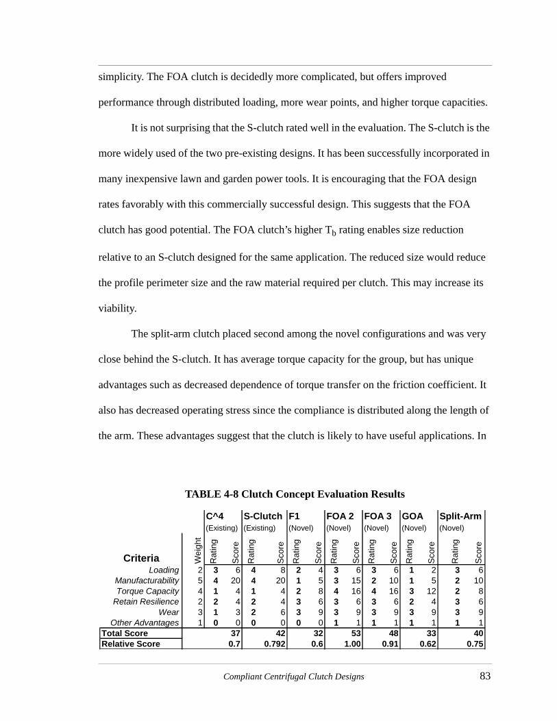
Compliant Centrifugal Clutch Designs 83
simplicity. The FOA clutch is decidedly more complicated, but offers improved
performance through distributed loading, more wear points, and higher torque capacities.
It is not surprising that the S-clutch rated well in the evaluation. The S-clutch is the
more widely used of the two pre-existing designs. It has been successfully incorporated in
many inexpensive lawn and garden power tools. It is encouraging that the FOA design
rates favorably with this commercially successful design. This suggests that the FOA
clutch has good potential. The FOA clutch’s higher Tb rating enables size reduction
relative to an S-clutch designed for the same application. The reduced size would reduce
the profile perimeter size and the raw material required per clutch. This may increase its
viability.
The split-arm clutch placed second among the novel configurations and was very
close behind the S-clutch. It has average torque capacity for the group, but has unique
advantages such as decreased dependence of torque transfer on the friction coefficient. It
also has decreased operating stress since the compliance is distributed along the length of
the arm. These advantages suggest that the clutch is likely to have useful applications. In
TABLE 4-8 Clutch Concept Evaluation Results
C^4 S-Clutch F1 FOA 2 FOA 3 GOA Split-Arm(Existing) (Existing) (Novel) (Novel) (Novel) (Novel) (Novel)
Criteria Wei
ght
Rat
ing
Sco
re
Rat
ing
Sco
re
Rat
ing
Sco
re
Rat
ing
Sco
re
Rat
ing
Sco
re
Rat
ing
Sco
re
Rat
ing
Sco
re
Loading 2 3 6 4 8 2 4 3 6 3 6 1 2 3 6Manufacturability 5 4 20 4 20 1 5 3 15 2 10 1 5 2 10Torque Capacity 4 1 4 1 4 2 8 4 16 4 16 3 12 2 8
Retain Resilience 2 2 4 2 4 3 6 3 6 3 6 2 4 3 6Wear 3 1 3 2 6 3 9 3 9 3 9 3 9 3 9
Other Advantages 1 0 0 0 0 0 0 1 1 1 1 1 1 1 1Total Score 37 42 32 53 48 33 40Relative Score 0.7 0.792 0.6 1.00 0.91 0.62 0.75

84 Compliant Centrifugal Clutches: Design, Analysis, and Testing
fact, the split-arm clutch scored better than the C4 clutch which is already used
successfully in several applications.
The GOA and F1 clutches did not score well relative to the other designs. Both
designs have relatively modest torques and manufacturability. While they both performed
adequately against the measures, neither has a strong advantage that would motivate
further examination and analysis.

85
CHAPTER 5 FOA Clutch Model and Application
The previous chapter showed that the FOA clutch scores well based on the clutch
evaluation criteria, but more information is needed to design and develop these clutches
for applications. Models for engagement speed and torque capacity ( ) are required to
design a clutch. For engagement speed, the model presented in Chapter 4 is expanded and
a model for the torque capacity ( ) is developed in this chapter. Predictions from both
models are compared to prototype test data. The resulting equations are demonstrated by
designing an FOA clutch to replace an existing S-clutch in a gas-powered string trimmer.
The FOA string-trimmer clutch was prototyped and tested in the string trimmer.
5.1 Engagement Model
5.1.1 Equation DevelopmentThe clutch engagement speed is found by calculating the deflection for
engagement and then solving the force equations to determine how much centrifugal force
is required to deflect the clutch into contact with the drum. The variables used in the
Tb
Tb

86 Compliant Centrifugal Clutches: Design, Analysis, and Testing
analysis are shown in Figure 5-1. The change in outer clutch radius at the contact point
( ) is approximately
(5.1)
where
(5.2)
and is the angle from vertical to the contact location. Substituting for in terms of
from Equation (4.19) results in
(5.3)
Figure 5-1 Explanation of variables used in the FOA clutch engagement model.
Fο
lθ
arcon
θcon
π/n
FSι
FSο
T1
T2
ro
ri
∆rcon
∆rcon ro roo–( ) π
n--- θ–
con a θ θo–( ) βcossin( )+cos=
βrclutch ro
πn---cos–
a-----------------------------------
asin=
θcon ro θ
∆rcon lπn--- θ–
con θsin π
n---cot θcos+
θosin πn---cot θocos+
– cos
a θ θo–( ) βcossin( )+
=

FOA Clutch Model and Application 87
This equation can be further simplified by assuming small angles to find
(5.4)
At contact, equals , the initial clearance between the clutch and the drum. Substi-
tuting for , the angular deflection at contact is
(5.5)
A rough approximation for the angle of deflection can be obtained by assuming
(5.6)
(5.7)
The accuracy of these approximations improves as the number of segments and the width
of the slots decrease. Once is known, the factors and in the force equations are
easily calculated.
Recall from Chapter 4,
(5.8)
An examination of Equation (4.21) and Equation (4.22) shows that both remaining terms
are linear with . Since the only remaining unknown in Equation (4.20) is the square of
the rotational velocity, the equation can be solved directly for at engagement. Substi-
tuting for and from equations (4.24) and (4.25) respectively, the expression for
is
∆rcon θ θo–( ) l θcos πn---cot θsin–
πn--- θ–
con a βcos( )+cos=
∆rcon δ
∆rcon
θ θo–δ
l θcos πn---cot θsin–
πn--- θ–
con a βcos( )+cos
------------------------------------------------------------------------------------------------------------------=
θcon 0≈
a 2rclutchπ
2n------sin≈
θ T1 T2
Fo k 1 k2+( ) θo θ–( ) lπ2--- π
n--- θ––
FSo×∠+ +
ω2
ω2
T1 T2 ω2

88 Compliant Centrifugal Clutches: Design, Analysis, and Testing
(5.9)
and are expressions for the and , respectively, due to an of one. The
spring constants and are found from Equation (A.3). Since both flexible segments
go through the same angular deflection, the spring constants of both segments equally
influence the engagement speed. Therefore, the relative stiffness of the two segments can
be adjusted so that the operating stress in both segments is similar.
5.1.2 Initial Test DataThese formulas were applied to the four prototype polypropylene FOA clutches to
predict the engagement speeds. The calculated engagement speeds are compared to the
measured engagement speeds in Table 5-1. The table includes the average and range of the
measured speeds. The predicted engagement speeds for two different values of the
modulus of elasticity are included to show its influence on the engagement speed.
Polypropylene, from which the designs were manufactured, experiences
significant stress relaxation. Additionally, the modulus of elasticity varies due to size,
ω2 k1 k2+( ) θ0 θ–( ) k
rcmFo
ω2------× l
FSo
ω2-------×+
-------------------------------------------
–=
Fo
ω2------ FSo
ω2------- Fo FSo ω2
k1 k2
TABLE 5-1 Measured and predicted engagement values for FOA clutches.
Clutch Name
Average Measured
Speed (rpm)
Range of Measured
Speeds (rpm)
Predicted Speed (rpm)(E=165 ksi)
Predicted Speed (rpm)(E=140 ksi)
FOA #1 715 693-718 799 735
FOA #2 477 292-497 517 475
FOA #3 535 521-548 540 497
FOA #4 502 474-520 574 532

FOA Clutch Model and Application 89
temperature, loading rates, and many other factors. The material behavior is very
nonlinear. Figure 5-2 shows the variation of measured stress strain curves for different pull
speeds and specimen sizes. Due to this extreme variation, the predicted engagement
speeds are shown using two different values for modulus of elasticity to calculate the
spring constants in the model.
Table 5-1 shows that the range in the measured engagement speeds is large for
FOA #2. One possible reason for this large variation is the existence of multiple stable
configurations for the clutch. While the clutch is geometrically symmetric, random inputs
may force it into other configurations that are also stable until the clutch begins contacting
20 in/min Pull Rate
0
100
200
300
400
500
600
700
800
0 0.002 0.004 0.006 0.008
Strain
Str
ess
1" thick
3/4" thick
1/4" thick
1/4" Thick Specimen
0
200
400
600
800
1000
1200
1400
1600
0 0.002 0.004 0.006 0.008 0.01 0.012
Strain
Str
ess
20 in/min
10 in/min
0.25 in/min
Figure 5-2 Polypropylene stress strain curves for different specimen sizes and pull rates. The slope of the curves varies by a factor of two due to the variations in specimen size and pull rate (Cook & Parker, 1996).

90 Compliant Centrifugal Clutches: Design, Analysis, and Testing
the drum. Once the clutch fully engages the drum, the circular drum should enforce
geometric symmetry.
Figure 5-3 shows a likely non-symmetric configuration of the clutch. Under some
operating conditions, the floating member may rest on one side of the hub as shown in
Figure 5-3(b) rather than be centered on the hub as illustrated in Figure 5-3(a). Since the
clearance between the hub and floating members is small (0.010-0.020 inches), the change
in the applied forces should be small. However, for the tested clutches, this effect could
reduce the clearance between the clutch and drum by twenty to forty percent. If the
engagement model were applied with the clearance reduced by 0.015 inches, the
engagement speed predictions for the prototype clutches would be reduced by 16.3
percent. The magnitude of this error depends on the relative size of the clearance between
the clutch and drum and between the hub and floating member.
Other factors may contribute significant error as well. The largest factor is an
irregularity in the outer diameter of the clutch after friction material is glued on the outside
Figure 5-3 (a) The assumed symmetrical position of the FOA clutch before engagement. The floating piece is centered on the hub with even spacing all the way around. (b) A likely configuration of the clutch before engagement. A non-symmetrical force such as gravity has caused the floating piece to rest against the hub on one side.
(a) (b)

FOA Clutch Model and Application 91
edge. A variation of 0.025 inches in the gap between the clutch and drum could account
for the systematic deviation from the predictions. Error might also be caused by a
consistent tolerance error on the NC mill used to manufacture the clutches. The final
dimensions are 0.002 inches below nominal for most clutches.
5.1.3 Engagement Speed RetestAn additional prototype was constructed to better test the validity of the
engagement speed model by reducing several error sources. This prototype was produced
from aluminum using wire EDM. The wire EDM was used to decrease the error due to
machining tolerances and to reduce the radius sizes required for the tools. Error from
stress relaxation in the polypropylene was eliminated by using aluminum. The stress
relaxation in the aluminum should be minimal under test conditions.
Cotton webbing was glued on the contact surfaces of the aluminum clutch and it
was tested using the same procedure as for the initial tests. The test was repeated five
times. For each test, the engagement speed was determined by finding the roots of a
quadratic fit to the clutch data. The average engagement speed was 844 rpm with a
standard deviation of 30 rpm and a range of 75 rpm. The predicted engagement speed was
849 rpm. This represents an error of 0.5%.
The increased accuracy of the second test using higher machining tolerances and a
material with a more constant modulus of elasticity supports the engagement speed model.
This data suggests that most of the error in the initial tests is due to stress relaxation and
machining tolerances.
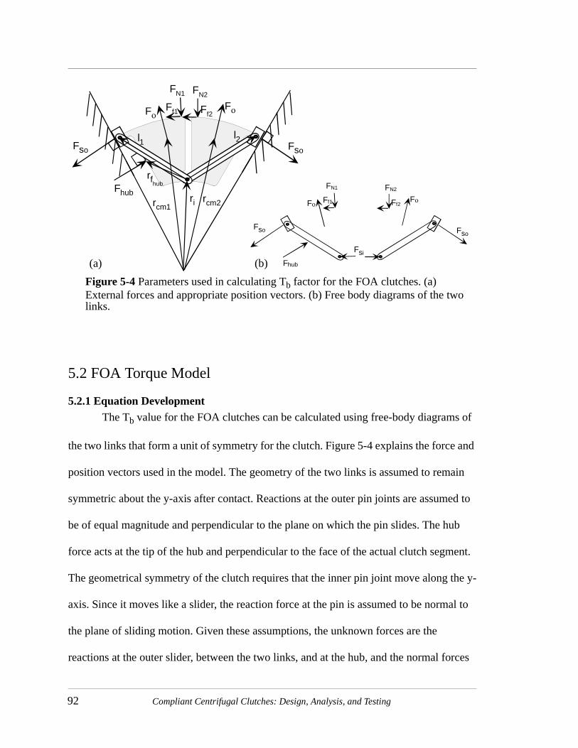
92 Compliant Centrifugal Clutches: Design, Analysis, and Testing
5.2 FOA Torque Model
5.2.1 Equation DevelopmentThe Tb value for the FOA clutches can be calculated using free-body diagrams of
the two links that form a unit of symmetry for the clutch. Figure 5-4 explains the force and
position vectors used in the model. The geometry of the two links is assumed to remain
symmetric about the y-axis after contact. Reactions at the outer pin joints are assumed to
be of equal magnitude and perpendicular to the plane on which the pin slides. The hub
force acts at the tip of the hub and perpendicular to the face of the actual clutch segment.
The geometrical symmetry of the clutch requires that the inner pin joint move along the y-
axis. Since it moves like a slider, the reaction force at the pin is assumed to be normal to
the plane of sliding motion. Given these assumptions, the unknown forces are the
reactions at the outer slider, between the two links, and at the hub, and the normal forces
FN1
Ff1
FN2
Ff2FοFο
Fso
l1l2
rcm1rcm2
Fhub
rfhub
Fso
ri
FN1
Ff1
FN2
Ff2FοFο
Fhub
Fso Fso
Fsi
(a) (b)
Figure 5-4 Parameters used in calculating Tb factor for the FOA clutches. (a) External forces and appropriate position vectors. (b) Free body diagrams of the two links.

FOA Clutch Model and Application 93
on both links. When calculating Tb, moments due to deflection of the compliant members
are not included since Tb represents the torque that would be transmitted if no springs
were present.
The force equilibrium equations for both links and the moment equilibrium
equation for link one are used to find the five unknowns. These five equations form the
matrix equation
(5.10)
where the elements of the matrix are:
(5.11)
(5.12)
(5.13)
(5.14)
(5.15)
(5.16)
(5.17)
(5.18)
mω2rcm1x
m– ω2rcm1y
rcm1 rij–( ) mω2rcm1( )×
m– ω2rcm2x
m– ω2rcm2y
f11 0 f13 f14 1–
f21 0 f23 f24 0
f31 0 f33 f34 0
0 f42 0 f44 1
0 f52 0 f54 0
FN1
FN2
Fhub
Fso
Fsi
=
f11 θconsin µ θconcos–( )=
f13πn--- θ θo–+ cos=
f14πn---cos=
f21 θconcos µ θconsin+( )–=
f23πn--- θ θo–+ sin=
f24πn---sin=
f31 rdrum θconsin i θconcos j+–( ) θconsin µ θconcos–( ) i θconcos µ θconsin–( ) j–[ ]×=
f33 rfhub
πn--- θ θo–+ cos i
πn--- θ θo–+ sin j+
×=

94 Compliant Centrifugal Clutches: Design, Analysis, and Testing
(5.19)
(5.20)
(5.21)
(5.22)
(5.23)
The matrix equation is easily solved with standard methods. The torque output without
any springs ( ) is
(5.24)
and the torque capacity is
, ω in rpm (5.25)
The torque output with springs is calculated from Equation (3.1).
f34 l1πn---cos i π
n---sin j+
×=
f42 µ θconcos θconsin+( )–=
f44 π πn---–
cos=
f52 µ θconsin θconcos–=
f54 π πn---–
cos=
Tns
Tns µrdrum FN1 FN2+( )=
Tb
Tns
ω2------106 µrdrum FN1 FN2+( )
ω2------------------------------------------106= =

FOA Clutch Model and Application 95
5.2.2 Test DataTable 5-2 summarizes the torque capacity (Tb) model predictions and measured
values. All of the model predictions are within 10% of the measured values. The
remaining variations are likely caused by variations in the coefficient of friction, outer
diameter of the clutch with the friction material, or material density.
5.3 Other Design Issues
There are many important considerations in designing and developing centrifugal
clutches. While this work does not undertake to analyze every important issue for the FOA
clutches, the work does yield some insights into the areas of wear, material selection, and
torque relationship to friction conditions. These insights are discussed in the following
sections.
5.3.1 WearDuring starting and stopping, the centrifugal clutches are in sliding contact with
the clutch drum. Over time, the sliding surfaces will abrade one another. The surface wear
will influence the engagement speed and the torque capacity as the contact location
TABLE 5-2 Measured and predicted torque capacities (Tb) for FOA clutches.
Clutch Name Measured Tb
Range of Measured
Values Predicted Tb Percent Error
FOA #1 2.20 0.156 2.32 +5.5
FOA #2 2.22 0.054 2.02 -9.0
FOA #3 2.60 0.051 2.57 -1.2
FOA #4 2.66 0.133 2.44 -8.3

96 Compliant Centrifugal Clutches: Design, Analysis, and Testing
changes. The clutch response to wear can be divided into two main factors: relative speed
of wear and sensitivity of clutch performance to wear.
Relative Speed of Wear
The speed of wear is primarily dependent on the particular materials in contact and
the conditions at the contact point. This issue, material selection, will be considered in a
later section. Over one hundred factors have been identified as important influences on
wear. Some of the most important include contact pressure, slipping speed, temperature,
and lubrication. Most of these factors are application specific. However, the relative
contact pressure for different concepts can be compared.
Increasing contact pressure increases the rate of wear. Therefore, decreasing
contact pressure is desirable. The contact pressure required to achieve a particular torque
will decrease as the number of contacting points increases and the radius of the clutch
drum increases. The FOA clutch prototypes had six to twelve contacting points compared
to just two contacting points per clutch for the S-clutches. This would suggest that FOA
clutches would have a longer wear life.
The contact pressure is also decreased by increasing the thickness of the clutch by
a larger factor than the mass. If the profile remains the same while the thickness is
increased, the torque capacity will increase while the contact pressure remains constant.
The profile should be adjusted so that the mass does not increase as much as the contact
area. This can be accomplished by drilling holes in the clutch shoes or otherwise
decreasing the shoe mass.

FOA Clutch Model and Application 97
Performance Sensitivity to Wear
As the contact surface wears, increased rotation of the clutch shoes is necessary for
engagement. The mechanical advantage of the inertial force will also change as the
location of the normal and friction forces changes. The increased rotation for engagement
will always increase the speed at which the clutch engages. However, the mechanical
advantage may increase or decrease. If the mechanical advantage increases with wear, the
torque capacity will increase to compensate, at least partially, for the higher engagement
speed.
The FOA clutch model indicates that as the contact location, indicated by ,
moves with wear ( increases), the torque capacity increases. The greater the difference
between the engagement speed and the operating speed, the more significant the effect of
the change in torque capacity. If the difference is large enough, the torque output would
actually increase with wear. This is an important consideration in torque sensitive
applications. Wear testing is necessary to understand the full effect of wear on FOA
clutches.
5.3.2 Material SelectionThree important aspects of material selection are wear characteristics, centrifugal
device suitability, and compliant mechanism suitability. Each of these issues is discussed
briefly.
Wear Characteristics
The speed of wear is dependent on the particular materials in contact. Usually, in
sliding contact between two different materials, one of the surfaces will lose more material
than the other. Generally, the materials should be selected so that the clutch wears more
θcon
θcon

98 Compliant Centrifugal Clutches: Design, Analysis, and Testing
quickly than the drum. Testing will be necessary to verify that the clutch has sufficient
wear life.
Centrifugal Device Suitability
Centrifugal devices are dependent on their mass for actuation force. Therefore,
materials with higher densities will have larger actuation forces. Often, a clutch needs to
fit within a limited space. If a higher density material is used, higher torque capacities are
possible within the space constraints.
Compliant Mechanism Suitability
Generally, compliant mechanisms are required to sustain specific deflections
rather than support a particular load. Therefore, the relative flexibility of the material is
more important than the material’s strength. The ratio of yield stress to the modulus of
elasticity indicates the relative flexibility of a material. Higher ratios denote materials that
can deflect farther before yielding (Howell, 1999).
In designing a centrifugal clutch, the magnitude of the modulus of elasticity is also
important since the spring force varies linearly with modulus of elasticity. The relative
magnitudes of the modulus of elasticity and the density will determine the relative
magnitudes of the centrifugal actuating force and the restraining force of the compliant
members. The relative magnitude limits the feasible combinations of engagement speed
and operating speed and torque. The feasible design space of a clutch concept will be
material dependent.
5.3.3 Torque Dependence on Coefficient of FrictionThe torque output of the FOA clutches is not related linearly to the coefficient of
friction. However, unlike the split arm clutches, the nonlinearity increases the dependence

FOA Clutch Model and Application 99
of torque output on the coefficient of friction. However, the nonlinearity is not extreme in
the common ranges for the coefficient of friction. Figure 5-5 shows the torque capacity
versus coefficient of friction for FOA #3. If the nominal coefficient of friction is 0.3, a
deviation of ten percent in the coefficient of friction would cause a fifteen percent change
in the torque capacity of the FOA #3. The FOA #4 clutch torque capacity would only vary
twelve percent under the same conditions due to differences in its geometry.
The coefficient of friction is highly sensitive to operating conditions such as
surface finish and particles between the mating surfaces. The nonlinearity of torque
capacity with coefficient of friction serves to amplify this effect. This may make the FOA
concept infeasible for some applications requiring precise torque outputs. However, the
geometry of the clutches can be selected to minimize this effect and in many applications,
the torque change with friction conditions is not a significant concern.
Figure 5-5 Variation of torque capacity with the coefficient of friction for the FOA #3 clutch.
Torque Capacity Vs. Friction
0
2
4
6
8
10
12
0 0.1 0.2 0.3 0.4 0.5 0.6
Coefficient of Friction
To
rqu
e C
apac
ity

100 Compliant Centrifugal Clutches: Design, Analysis, and Testing
Self-locking conditions
In clutches and brakes with an aggressive, or self-energizing member, there is
always a danger that the device could be self-locking. The friction forces on aggressive
members apply moments that increase the normal force. This increases torque output, but
if the actuating moment due to friction is larger than the opposing moment from the
normal force(s), the clutch or brake will seize. This condition is called self-locking.
Self-locking disrupts the normal operating mode of a clutch and could destroy
clutch, load, or other equipment in the powertrain. Therefore, it is vital that this condition
be considered in designing any clutch with an aggressively oriented member. The FOA
clutch has aggressively oriented members so it can experience self-locking conditions.
However, each section of the FOA clutch has only one aggressive frictional force per
section with two normal forces and one frictional force acting to oppose the aggressive
force. This decreases the likelihood of achieving self-locking conditions with the FOA
clutches.
Self-locking behavior is a function of geometry and the coefficient of friction.
Self-locking friction conditions are easily identified from a graph of torque capacity
versus the coefficient of friction. Such a graph can be created by varying the coefficient of
friction input to the torque model. At the self-locking value of the coefficient of friction,
the torque capacity curve is discontinuous. Figure 5-6 shows such a graph for the FOA #3.
If the coefficient of friction is greater than or equal to the critical value, the clutch will
lock. The approximate value of the coefficient of friction for self-locking behavior was
identified for the prototype FOA geometries.
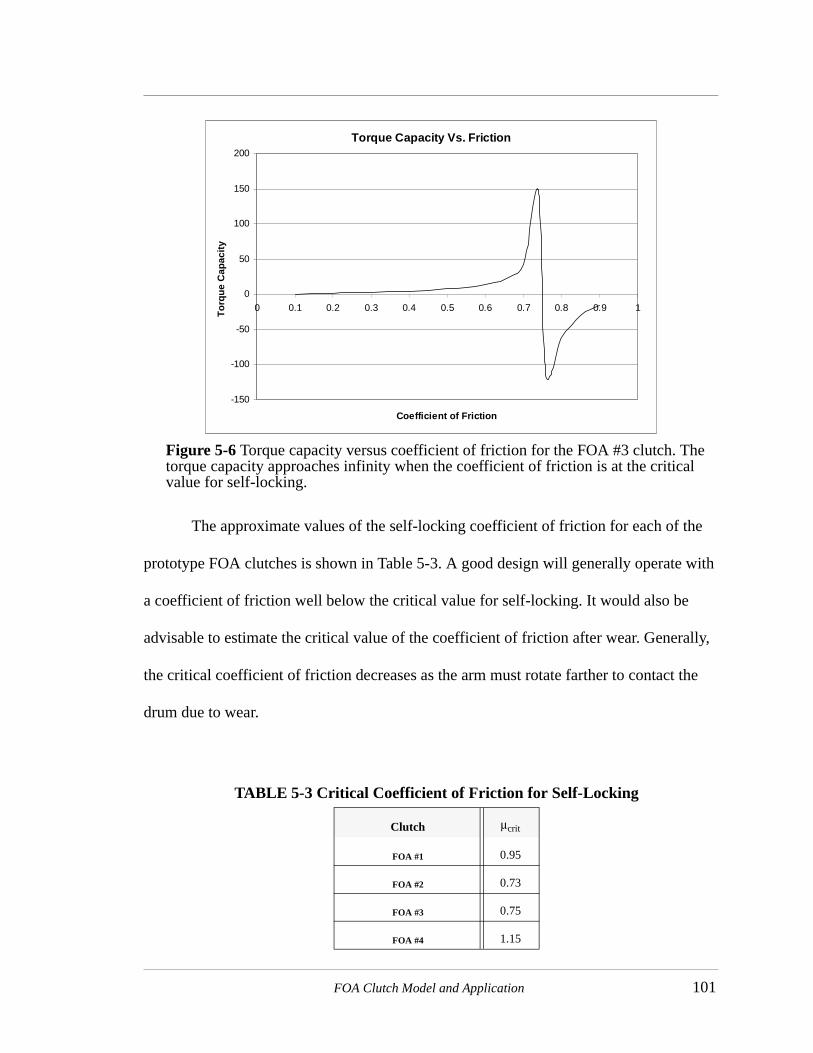
FOA Clutch Model and Application 101
The approximate values of the self-locking coefficient of friction for each of the
prototype FOA clutches is shown in Table 5-3. A good design will generally operate with
a coefficient of friction well below the critical value for self-locking. It would also be
advisable to estimate the critical value of the coefficient of friction after wear. Generally,
the critical coefficient of friction decreases as the arm must rotate farther to contact the
drum due to wear.
Torque Capacity Vs. Friction
-150
-100
-50
0
50
100
150
200
0 0.1 0.2 0.3 0.4 0.5 0.6 0.7 0.8 0.9 1
Coefficient of Friction
To
rqu
e C
apac
ity
Figure 5-6 Torque capacity versus coefficient of friction for the FOA #3 clutch. The torque capacity approaches infinity when the coefficient of friction is at the critical value for self-locking.
TABLE 5-3 Critical Coefficient of Friction for Self-Locking
Clutch µcrit
FOA #1 0.95
FOA #2 0.73
FOA #3 0.75
FOA #4 1.15

102 Compliant Centrifugal Clutches: Design, Analysis, and Testing
5.4 FOA Concept Enhancement
A major limitation of the FOA concept is the unpredictability observed in the
engagement speed due to the clearance between the clutch and drum. A simple calculation
showed that the clutch-hub clearance could decrease the engagement speed of the
prototype clutches by over sixteen percent from ideal (page 90). The clutch performance
might be improved by reducing or using the effect.
5.4.1 Reducing Effect of Clutch-Hub ClearanceIf the effect of the clutch-hub clearance on engagement speed were reduced, this
would increase the accuracy of the engagement speed model and the clutch reliability.
This could be accomplished in at least four ways:
1. Modify the dimensions and reducing their tolerance. This could increase cost signifi-cantly.
2. Manufacture the hub larger than the floating member so that the floating member must be stretched for assembly. This would eliminate the clearance between the two pieces.
3. Place a layer of resilient material in several locations around the hub to fill the gap.
4. Increase the magnitude of the clearance between the clutch and drum relative to the clearance between the floating member and the hub. The amount of deviation in engagement speed due to the clutch-hub clearance is approximately equal to the square root of the ratio of the clutch-hub clearance to the clutch-drum clearance.
5.4.2 Using the Clutch-hub Clearance EffectWhen the clutch assumes the non-symmetrical position shown in Figure 5-3(b),
only one segment of the clutch engages initially. As the speed and the contact forces
increase, more segments of the clutch will contact the drum until the clutch is in a
symmetric configuration with all segments in contact with the drum. This effect might be
adjusted or magnified to increase the starting smoothness of the FOA clutches.

FOA Clutch Model and Application 103
5.5 String Trimmer Design Example
String trimmers are common applications for low-cost centrifugal clutches. Many
string trimmers already use an S-clutch, but may benefit from an FOA clutch. To show the
advantages of an FOA clutch, the S-clutch of a Homelite VersaTool string trimmer was
replaced with an FOA clutch. This trimmer actually uses a stack of two identical S-
clutches each 1/8 inch thick shown in Figure 5-7. A potential advantage of the FOA clutch
is the possibility of using just one 1/8 inch thick FOA clutch because of its higher torque
capacity.
5.5.1 Design RequirementsThe design requirements specified for the string trimmer example are engagement
speed, operating speed, torque capacity, and maximum clutch diameter. The idle speed
and operating speed parameters were measured for the trimmer. The torque capacity was
estimated from the maximum torque capacity of the original S-clutch. Maximum diameter
was determined from the size of the current clutch drum. The torque capacity (Tb) of the
Figure 5-7 Two S-clutches from a Homelite Versatool string trimmer. The outer diameter of the clutches is 2.41 inches.

104 Compliant Centrifugal Clutches: Design, Analysis, and Testing
existing S-clutch was estimated using the method outlined in “S-Clutch” on page 63. The
values for the design requirements are shown in Table 5-4.
5.5.2 Proposed DesignThe FOA concept was chosen because it ranked highest in the evaluation. A clutch
with four symmetrical sections was selected for its higher torque capacity while
maintaining a reasonable profile perimeter. The outer radius of the clutch was chosen as
the outer radius of the S-clutch. The thickness was chosen as 1/8 inch thick to illustrate the
potential space and weight savings of an FOA clutch. The design was manufactured from
low carbon steel ( ) to match the S-clutch that it replaces. The exact parameters
of the proposed design are listed in Table 5-5.
5.5.3 Design PredictionsThe models were applied to the FOA design to verify that it would meet the
required performance parameters. The calculated value of Tb for a coefficient of friction
of 0.25 is 0.718 in*lb/1000 rpm. The clutch was designed for a Tb higher than required to
allow for the nonlinearity in the torque output due to changes in the coefficient of friction.
The model predicts an engagement speed of 6480 rpm. This is well above the engine idle
TABLE 5-4 Design Requirements for FOA string trimmer clutch.
Requirement Value
Idle Speed 5500 RPM
Operating Speed 9500 RPM
Tb 0.575 in*lb/1000 rpm
Max Thickness 0.420 in
Shaft Diameter 0.330 in
E 30x106≈

FOA Clutch Model and Application 105
speed to allow for no-load idling. Since the torque curve of the engine was not available to
permit evaluation of the motor-clutch dynamics, this high engagement speed was selected
to assure that the motor would have adequate torque at the engagement speed. However,
this may reduce the output torque excessively. The estimated coefficient of friction for
self-locking is 1.01. This value is much higher than the actual coefficient of friction and
there should be no danger of self-locking even after significant wear. The design was
manufactured using wire EDM. The prototype is shown in Figure 5-8(a).
5.5.4 Prototype TestingThe prototype string trimmer clutch was manufactured and installed in the string
trimmer as shown in Figure 5-8(b). The string trimmer was reassembled and tested. For
TABLE 5-5 Parameter values for String Trimmer FOA.
Clutch Parameters Values
Rclutch (in) 1.205
Arm Volume (in3) 0.01097
Rcm(in) 12.0
θcm (deg) 21.0
li (in) 0.140
ti (in) 0.050
lo (in) 0.240
to (in) 0.050
Rdrum (in) 1.2175
n 4
t (in) 0.125
Ri (in) 0.484
µ 0.25

106 Compliant Centrifugal Clutches: Design, Analysis, and Testing
the test, the string trimmer was used to cut lawn grass, edge along a sidewalk, and trim
overhanging bush branches. The test was recorded using a video camera.
During the initial test, the FOA clutch performed adequately. The string would
remain largely motionless while the clutch was idling. At times, the string did turn, but
when the head was placed against the ground or some other resistance, the string stopped
readily. During engagement, the engine sometimes stalled. This may be because the clutch
engages too hard or at too low of a speed. The torque output from the string trimmer was
adequate for all of the trimming tasks performed. It continued to trim very well even when
the resistance was increased by pressing the head against the ground. When disassembling
the trimmer after testing, grease from the shaft was found inside the clutch drum.
The test was repeated with a different mounting arrangement after it was noted that
there was axial friction between the drum and the clutch mounting hardware. The
mounting hardware was modified for the second test. With the modified mounting
hardware, the clutch performance was greatly improved. At idle, the trimming head was
Figure 5-8 (a) The prototype FOA clutch for the string trimmer. (b) The FOA clutch mounted on the string trimmer.
(a) (b)

FOA Clutch Model and Application 107
motionless and the engine accelerated the trimmer head to operating speed without
difficulty.
For comparison, the FOA clutch was replaced with an S-clutch and the test was
repeated. With the S-clutch, the engagement was smooth with a noticeable delay between
engine and string acceleration. The torque seemed adequate for the tests performed.
5.5.5 FOA String Trimmer ConclusionsThe FOA design performs the basic clutch functions in the string trimmer. The
torque output of the clutch may have been affected significantly by the grease in the clutch
drum but was still adequate for the tests performed. Due to the nonlinearity of the FOA
torque with friction coefficient, the grease may have a much more significant torque
capacity impact on the FOA clutch than the original S-clutch. Further work is also needed
to improve the clutch-engine dynamics so that the clutch engages smoothly without
overloading the engine and supplies all necessary torque.
More work is needed to fully assess the potential of the FOA clutch. The
engagement speeds of the FOA clutch and the S-clutch should be compared. The
engagement speed of the FOA clutch may need adjustment to better approximate the S-
clutch performance. A wear test of the FOA clutch is also needed to see whether it can
maintain performance for the required clutch life. If the clutch wear life is not adequate, a
lining of friction material on the contact surface may be added to increase the life.

108 Compliant Centrifugal Clutches: Design, Analysis, and Testing

109
CHAPTER 6 Conclusions and Recommendations
Compliant mechanism design techniques were used to analyze compliant
centrifugal clutches and to develop effective new centrifugal clutch concepts. The pseudo-
rigid-body model (PRBM), rigid-body replacement synthesis, force-deflection analysis,
compliance potential evaluation, and compliant concept evaluation were employed in this
work. These methods were instrumental in developing and modeling four novel compliant
centrifugal clutch designs, modeling two existing designs, and identifying a concept with
excellent potential for low-cost centrifugal clutch applications. Additional novel designs
developed through this work also show good potential. All of the designs were prototyped
and tested to measure their torque-speed relationships.
6.1 Contributions
6.1.1 Modeling Two Existing ClutchesTwo existing compliant centrifugal clutches were modeled using the pseudo-rigid-
body model. The PRBM permits quick evaluation of initial designs with much less time
and cost than is possible with finite element methods. This simplicity will allow these

110 Compliant Centrifugal Clutches: Design, Analysis, and Testing
clutches to be applied to new applications with relatively little effort. The new model is a
significant improvement over trial and error methods used previously.
6.1.2 Floating Opposing Arm (FOA) ClutchAfter modeling, testing, and evaluation, the floating opposing arm (FOA) clutch
emerged as the most promising clutch concept developed through this work. This clutch
combines the high torque output of an aggressively oriented clutch shoe with the smoother
starting of a non-aggressive shoe by connecting both together. This permitted an increase
of over two hundred percent in torque capacity relative to existing compliant centrifugal
clutches of the same size and material. The clutch also consists of a separate hub which
transfers torque from the drive shaft to reduce force in the flexible segments. This
increases the design space of the FOA clutches. The clutch also performs equally well
when rotated either direction.
Models were developed for predicting the torque transfer and engagement speed of
the clutch. These models successfully predicted the performance of the prototype clutches.
Other design issues such as material selection and wear were discussed briefly. Finally,
the FOA concept was designed and tested in a gasoline-engine-powered string trimmer.
The test demonstrated that the FOA clutch has the potential to replace an existing
compliant centrifugal clutch and reduce required space and material due to its higher
torque capacity.
6.1.3 Split-Arm ClutchThe split-arm clutch is another novel design developed through this work.
Preliminary tests show that the clutch can generate more torque than the existing
compliant centrifugal clutch types for a given size and material. This clutch has the added

Conclusions and Recommendations 111
advantage of simulating flexible trailing shoe clutches but with a reduced part count. This
clutch is only one piece. The primary advantage of this clutch is that it is less sensitive to
changes in coefficient of friction than the other compliant designs. This allows the split-
arm clutch to perform more consistently under varying friction conditions.
6.1.4 Demonstration of Compliant Mechanism TechniquesThe whole of the work demonstrates many new methods for developing,
analyzing, and evaluating compliant mechanisms. They were successfully integrated
together to develop, analyze, and evaluate new design solutions to an old device: the
centrifugal clutch. The new designs formulated through this work demonstrate clear
advantages over the existing designs, both compliant and rigid-body.
6.2 Recommendations
6.2.1 Advance the Promising Novel DesignsAs mentioned, several promising designs have been developed through this work.
Preliminary analysis, modeling, and testing have been performed. However, further
design, analysis, and testing is necessary to apply them to specific applications. The work
to be done includes wear testing, fatigue testing, and material selection.
6.2.2 Apply the Clutch Concepts to Overspeed BrakesBy securing the clutch drum, a centrifugal clutch becomes an overspeed brake.
Therefore, any of the designs discussed in this work might work well as an overspeed
brake. However, a good centrifugal clutch is not always a good overspeed brake. Further
work should be done to identify the characteristics of a good overspeed brake and evaluate
the relative potential of the various clutch concepts as brakes.

112 Compliant Centrifugal Clutches: Design, Analysis, and Testing
6.2.3 Explore Other Centrifugal Clutch ConceptsThere are always numerous solutions to a design problem. However, two
promising solution classes have not yet been examined. These two design areas deserve
further attention.
Clutches with Reduced Torque at High Speed
The torque output of centrifugal clutches increases with the square of the rotational
velocity indefinitely. The only factor to limit torque output of many centrifugal clutches is
the ultimate strength of the members carrying the load. However, even then, broken
components of the clutch may wedge between the remaining clutch and the drum to
continue transferring power. This effect can be very dangerous in many applications. If
the clutch is accelerated beyond the normal operating speed, it may easily transmit
dangerous amounts of torque that could damage other machinery or injure its operators.
Centrifugal clutches can be made with torque capacity that levels off or even
decreases at excessive speeds. Such clutches have been developed already. One example
is documented in Patent Number 4446954 (Weiss, 1984). This design is shown in Figure
6-1.
This clutch concept acts much like a normal clutch at lower speeds. It has a large
mass that provides the centrifugal actuation force. It also has a smaller secondary mass
located closer to the clutch center to limit its input force. However, the centrifugal force at
the second mass has a high mechanical advantage. As the speed increases beyond the safe
operating range, the force on the secondary mass increases until it disengages the clutch.

Conclusions and Recommendations 113
This idea should be examined and compliant configurations for achieving this
behavior should also be sought. Designing a compliant clutch with this safety feature
could drastically reduce the part count and cost of such a clutch. The patented design has
at least seventeen parts. A compliant design might be possible with only one or two parts.
This part count reduction is much more dramatic than the reduction achieved for the
centrifugal clutches analyzed in this work.
Improved Starting Smoothness Through a Multi-input Clutch
This work did not present any methods for improving the starting smoothness of
compliant centrifugal clutches. All of the clutches considered in this work maintained a
quadratic relationship between torque and speed. However, several rigid-body designs
were reviewed which had torque responses that were a function of both speed and time.
The addition of time as a variable in the torque response increases starting smoothness.
The time variability of those clutches was achieved by forcing fluid to flow through an
Figure 6-1 A patented clutch concept that reduces torque at high speeds. The joints near the rotational axis are weighted to overcome the restraining springs to move outward at high speeds. Small forces at the weights have a large effect because the links are near toggle.

114 Compliant Centrifugal Clutches: Design, Analysis, and Testing
orifice. This principle could be applied to compliant clutches, but the additional
complexity from incorporating a fluid would likely remove the cost advantage of
compliant clutches.
A similar increase in starting smoothness could be achieved by adding a second
input force to the mechanism that is proportional to the difference in the speeds of the
driver and the driven (clutch and drum). This force would act against the energizing
centrifugal force to limit torque output while there was a speed difference. When the
difference in speeds is greatest, the limiting force would limit the torque the most. As the
load approaches the input speed, the clutch would reach the operating torque as the second
force went to zero. This transitory effect would slow the response of the clutch torque to
changes in speed.
The second input force proportional to the speed difference might be created by
means of a viscous friction between elements rotating at the two different speeds. Such a
force could be generated by a bearing. One bearing race could be fixed to the drum and the
other attached to an element of the clutch with significant mechanical advantage to limit
the torque output. Such a clutch is illustrated in Figure 6-2(a). Figure 6-2(b) shows the
PRBM for one half of the clutch and the opposing input forces that would increase its
starting smoothness. The clutch arm is the same as for the C4 design except that a second
link is connected between the bearing and the clutch arm. This second link applies a force
away from the clutch drum during start-up conditions.

Conclusions and Recommendations 115
6.2.4 Improve Torque ModelThe torque model for the clutches only includes two parameters, a torque capacity
(Tb) and engagement speed. This model was satisfactory for most of the clutches, but
some had linear terms that weren’t accounted for by this model. A new model should be
developed to better model these clutches.
6.3 Conclusion
This thesis demonstrates that compliant mechanism design methods can produce
new design concepts, even for a simple, existing design challenge. This work has
developed four original concepts that have several potential advantages beyond existing
designs—FOA, GOA, Split-arm, and F1. The FOA design is particularly promising
because it doubles torque capacity relative to the S-clutch, a commercial compliant design
Figure 6-2 (a) A clutch concept with improved starting smoothness. (b) A PRBM for half of the clutch showing the two counteracting input forces that would slow the clutch’s torque response.
(a) (b)

116 Compliant Centrifugal Clutches: Design, Analysis, and Testing
currently produced, while maintaining reasonable manufacturability. This exercise in
developing and analyzing new compliant solutions to a design problem demonstrates the
value of the methods used—pseudo-rigid-body model, rigid-body replacement synthesis,
force-deflection analysis, compliance potential evaluations, and compliant concept
evaluation. In particular, this work shows that each of these methods, though developed
individually for specific parts of the design process, can be unified into an effective
development process.

117
REFERENCES
Achi, P. B. U., 1986, “Design and Testing of an Automatic Clutch”, Sadhana, Vol. 9, No. 3, pp. 23-238.
Ananthasuresh, G.K., Kota, S. and Gianchandani, Y., 1994, “A Methodical Approach to the Design of Compliant Mechanisms,” Solid-State Sensor and Actuator Workshop, Hilton Head Island, South Carolina, pp. 189-192.
Ananthasuresh, G.K., and Kota, S., 1995, “Designing Compliant Mechanisms,” Mechanical Engineering, Vol. 117, No. 11, pp. 93-96.
Bisshopp, K.E. and Drucker, D.C., 1945, “Large Deflection of Cantilever Beams,” Quarterly of Applied Mathematics, Vol. 3, No. 3, pp. 272-275.
Boronkay, T., and Mei, C., 1970, “Analysis and Design of Multiple Input Flexible Link Mechanisms,” Journal of Mechanisms, Vol. 5, No. 1, pp. 29-49.
Berglund, M. D., 1998, “A Methodology for the Evaluation and Selection of Acceptable Design Concept Alternatives for Compliant Mechanisms,” M.S. Thesis, Brigham Young University, Provo, Utah.
Burns, R.H., 1964, “The Kinetostatic Synthesis of Flexible Link Mechanisms,” Ph.D. Dissertation, Yale University, New Haven, Connecticut.
Burns, R.H. and Crossley, F.R.E., 1968, “Kinetostatic Synthesis of Flexible Link Mechanisms,” ASME Paper No. 68-MECH-36.
Chase, T. R., Erdman, A. G., and Marier, G., 1991, “Design of an Improved Variable-Sheave V-Belt Drive,” Mechanism and Machine Theory, Vol. 26, No. 6, pp. 579-592.
Cook, B., and Parker, B. “Tensile Test Analysis of Polypropylene at Different Sizes and Pull Speeds”, Unpublished class project for Mechanical Engineering 352, December 1996.
Cragun, R., Jensen, B., Lyon, S. M. Unpublished research data used with permission of authors, 1998.

118 An Investigation of Compliant Mechanisms as Centrifugal Clutches
Dekhanov, V. I. and Makhtinger, V. L., 1987, “Variable Drive of Centrifugal Separator,” Chemical and Petroleum Engineering, Vol. 23, No. 1-2, pp. 3-5.
Derderian, J.M., Howell, L.L., Murphy, M.D., Lyon, S.M., and Pack, S.D., 1996, “Compliant Parallel-Guiding Mechanisms,” Proceedings of the 1996 ASME Design Engineering Technical Conferences, 96-DETC/MECH-1208.
Dietzsch, G., Frers, G., Henning, K., and Lux, H., 1977, “Rotor for Centrifugal Clutch,” United States Patent No. 4016964.
Edwards, B.T., Jensen, B. D., and Howell, L.L., 1996, “A Pseudo-Rigid-Body model for Functionally Binary Pinned-Pinned Segments Used in Compliant Mechanisms,” Proceedings of the 1999 ASME Design Engineering Technical Conferences, DETC99/DAC-8644.
Erdman, A.G. and Sandor, G.N., 1997, Mechanism Design: Analysis and Synthesis, Vol. 1, 3rd Ed., Prentice Hall, New Jersey.
Frecker, M.I., Kikuchi, N., and Kota, S., 1996, “Optimal Synthesis of Compliant Mechanisms to Meet Structural and Kinematic Requirements - Preliminary Results,” Proceedings of the 1996 ASME Design Engineering Technical Conferences, 96-DETC/DAC-1497.
Frecker, M.I., Kota, S., and Kikuchi, N., 1997, “Use of Penalty Function in Topological Synthesis and Optimization of Strain Energy Density of Compliant Mechanisms,” Proceedings of the 1997 ASME Design Engineering Technical Conferences, DETC97/DAC-3760.
Gandhi, M. and Thompson, B., 1980, “The Finite Element Analysis of Flexible Components of Mechanical Systems Using a Mixed Variational Principle,” ASME Paper No. 80-DET-04.
Goodling, E. C., 1974, “Fighting High Energy Costs with Centrifugal Clutches,” Machine Design, Vol. 46, No. 23, pp. 119-124.
Goodling, E. C., 1977, “Trailing Shoe Type Centrifugal Clutch-Design Principles and Characteristics,” ASME Papers, DET-126.
Gorski, W., 1976, “A Review of Literature and a Bibliography on Finite Elastic Deflections of Bars,” Transactions of the Institute of Engineers, Australia, Civil Engineering Transactions, Vol. 18, No. 2, pp. 74-85.
Gruden, J. M., and Brooks, R. B., 1999, “Centrifugal Clutch for Power Door Locks” United States Patent No. 5862903.

References 119
Hartenberg, R.S. and Denavit, J., 1964, Kinematic Synthesis of Linkages, McGraw-Hill Book Company, New York, New York.
Her, I., 1986, “Methodology for Compliant Mechanism Design,” Ph.D. Dissertation, Purdue University, West Lafayette, Indiana.
Hill, T.C., Midha, A., 1990, “A Graphical User-Driven Newton-Raphson Technique for use in the Analysis and Design of Compliant Mechanisms,” Journal of Mechanical Design, Trans. ASME, Vol. 112, No. 1, pp. 123-130.
Howell, L.L. and Midha, A., 1994a, “A Method for the Design of Compliant Mechanisms with Small-Length Flexural Pivots,” ASME Journal of Mechanical Design, Vol. 116, No. 1, pp. 280-290.
Howell, L.L. and Midha, A., 1994b, “The Development of Force-Deflection Relationships for Compliant Mechanisms,” Machine Elements and Machine Dynamics, DE-Vol. 71, 23rd ASME Biennial Mechanisms Conference, pp. 501-508.
Howell, L.L., Midha, A., and Murphy, M.D., 1994a, “Dimensional Synthesis of Compliant Constant-Force Slider Mechanisms,” Machine Elements and Machine Dynamics, DE-Vol. 71, 23rd ASME Biennial Mechanisms Conference, pp. 509-515.
Howell, L.L. and Midha, A., 1995a, “Parametric Deflection Approximations for End-Loaded, Large-Deflection Beams in Compliant Mechanisms,” ASME Journal of Mechanical Design, Vol. 117, No. 1, pp. 156-165.
Howell, L.L. and Midha, A., 1995b, “Determination of the Degrees of Freedom of Compliant Mechanisms Using the Pseudo-Rigid-Body Model Concept,” Proceedings of the Ninth World Congress on the Theory of Machines and Mechanisms, Milano, Italy, Vol. 2, pp. 1537-1541.
Howell, L.L. and Midha, A., 1995c, “The Effects of a Compliant Workpiece on the Input/Output Characteristics of Rigid-Link Toggle Mechanisms,” Mechanism and Machine Theory, Vol. 30, No. 6, pp. 801-810.
Howell, L.L, Midha, A., and Norton, T.W., 1996, “Evaluation of Equivalent Spring Stiffness for Use in a Pseudo-Rigid-Body Model of Large-Deflection Compliant Mechanisms,” ASME Journal of Mechanical Design, Vol. 118, No. 1, pp. 126-131.
Howell, L.L. and Midha, A., 1996a, “Parametric Deflection Approximations for Initially Curved, Large-Deflection Beams in Compliant Mechanisms,” Proceedings of the 1996 ASME Design Engineering Technical Conferences, 96-DETC/MECH-1215.

120 An Investigation of Compliant Mechanisms as Centrifugal Clutches
Howell, L.L. and Midha, A., 1996b, “A Loop-Closure Theory for the Analysis and Synthesis of Compliant Mechanisms,” Journal of Mechanical Design, March 1996, Vol. 118, pp. 121-125.
Howell, L., 1999, “Compliant Mechanisms,” Notes for MeEn 538, Brigham Young University, Provo, Utah.
Jensen, B., 1998, “Identification of Macro- and Micro- Compliant Mechanism Configurations Resulting in Bistable Behavior,” M.S. Thesis, Brigham Young University, Provo, Utah.
Kellerman, R. and Fischer, J. L., 1976, “Centrifugal Clutch with One Piece Rotor,” United States Patent No. 3945478.
Kramer, M., Schmid, W., and Cramer, H., 1982, “Electric Centrifugal Switch,” United States Patent No. 4315118.
Mettlach, G.A. and Midha, A., 1996, “Using Burmester Theory in the Design of Compliant Mechanisms,” Proceedings of the 1996 ASME Design Engineering Technical Conferences, 96-DETC/MECH-1181.
Midha, A., Norton, T.W., and Howell, L.L., 1994, “On the Nomenclature, Classification, and Abstractions of Compliant Mechanisms,” Journal of Mechanical Design, March 1994, Vol. 116, pp. 270-279.
Moore, H. O., 1980, “Centrifugal Switch,” United States Patent No. 4182952.
Murphy, M.D., Midha, A., and Howell, L.L., 1994a, “Type Synthesis of Compliant Mechanisms Employing a Simplified Approach to Segment Type,” Mechanism Synthesis and Analysis, DE-Vol. 70, 23rd ASME Biennial Mechanisms Conference, pp. 51-60.
Murphy, M.D., Midha, A., and Howell, L.L., 1994b, “Methodology for the Design of Compliant Mechanisms Employing Type Synthesis Techniques with Example,” Mechanism Synthesis and Analysis, DE-Vol. 70, 23rd ASME Biennial Mechanisms Conference, pp. 51-60.
Nielson, A.J. and Howell, L.L., 1998, “Compliant Pantographs via the Pseudo-Rigid-Body Model,” Proceedings of the 1998 ASME Design Engineering Technical Conferences, DETC98/MECH-5930.
Norton, R. L., 1999, Design of Machinery, Second Edition, McGraw-Hill Inc., Boston.
Norton, R. L., 1998, Machine Design: An Integrated Approach, Prentice-Hall, New Jersey, 959-988.

References 121
Orthwein, W.C., 1986, Clutches and Brakes Design and Selection, Marcel Dekker, Inc., New York, New York.
Opdahl, P.G., 1996, “Modeling and Analysis of Compliant Bi-Stable Mechanisms Using the Pseudo-Rigid-Body Model,” M.S. Thesis, Brigham Young University, Provo, Utah.
Opdahl, P.G., Jensen, B.D., and Howell, L.L., 1998, “An Investigation into Compliant Bistable Mechanisms”, ASME 25th Biennial Mechanisms Conference, to be held in Atlanta, Georgia, August 1998.
Parkinson, M.B., Howell, L.L, and Cox, J., 1997, “A Parametric Approach to the Optimization-Based Design of Compliant Mechanisms,” Proceedings of the 1997 ASME Design Engineering Technical Conferences, DETC97/DAC-3763.
Paul, B., 1979b, Kinematics and Dynamics of Planar Machinery, Prentice-Hall, Inc., Englewood Cliffs, New Jersey.
Roach, G.M., 1998,”An Investigation of Compliant Over-Running Ratchet and Pawl Clutches,” M.S. Thesis, Brigham Young University, Provo, Utah.
Roach, G. M. and Howell, L. L., 1999, “Evaluation and Comparison of Alternative Compliant Over-running Clutch Designs,” 1991 ASME Design Engineering Technical Conferences, DETC99/DAC-8619.
Roach, G.M., Lyon, S.M., and Howell, L.L., 1998, “A Compliant, Over-Running Ratchet and Pawl Clutch with Centrifugal Throw-Out,” Proceedings of the 1998 ASME Design Engineering Technical Conferences, DETC98/MECH-5819.
Salamon, B.A., 1989, “Mechanical Advantage Aspects in Compliant Mechanisms Design,” M.S. Thesis, Purdue University, West Lafayette, Indiana.
Salamon, B.A. and Midha, A., 1998, “An Introduction to Mechanical Advantage in Compliant Mechanisms,” Journal of Mechanical Design, Trans. ASME, Vol. 120, No. 2, pp. 311-315.
Saxena, A., Kramer, S. N., 1998, “A Simple and Accurate Method for Determining Large Deflections in Compliant Mechanisms Subjected to End Forces and Moments”, Journal of Mechanical Design, Trans. ASME, Vol. 120, No. 3, pp. 392-400. Erratum Vol. 121, No. 2, pp. 194.
Sevak, N.M., McLarnan, C.W., 1974, “Optimal Synthesis of Flexible Link Mechanisms with Large Static Deflections,” AME Paper No. 74-DET-83.

122 An Investigation of Compliant Mechanisms as Centrifugal Clutches
Shigley, J. E. and Mischke, C. R., 1989, Mechanical Engineering Design, Fifth Edition, pp. 627-664.
Shimizu, Y. and Ogura, M., 1987, “Centrifugal Clutch Instantly Engageable and Disengageable,” United States Patent No. 4687085.
Shoup, T.E., 1972, “On the Use of the Nodal Elastica for the Analysis of Flexible Link Devices,” Journal of Engineering for Industry, Trans. ASME, Vol. 94, No. 3, pp. 871-875.
Shoup, T.E. and McLarnan, C.W., 1971a, “A Survey of Flexible Link Mechanisms Having Lower Pairs,” Journal of Mechanisms, Vol. 6, No. 3, pp. 97-105.
Shoup, T.E. and McLarnan, C.W., 1971b, “On the Use of the Undulating Elastica for the Analysis of Flexible Link Devices,” Journal of Engineering for Industry, Trans ASME, pp. 263-267.
Shultz, W. L., 1996, “Bi-directional centrifugal clutch,” United States Patent No. 5503261.
South, D.W. and Mancuso, J.R., 1994, Mechanical Power Transmission Components, Marcel Dekker, Inc., New York, New York.
St. John, R. C., 1975, “Centrifugal Clutch Has Gentle Touch,” Power Transmission Design, Vol. 17, No. 3, pp. 40-42.
St. John, R. C., 1979, “Centrifugal Clutch Basics,” Power Transmission Design, Vol. 21, No. 3, pp. 52-55.
Suchdev, L. S. and Campbell, J. E., 1989, “Self Adjusting Rotor for a Centrifugal Clutch,” United States Patent No. 4821859.
Timoshenko, S. and Young, D.H., 1948, Advanced Dynamics, 1st Edition, McGraw-Hill Book Company, Inc., New York.
Timoshenko, S. and Young, D.H., 1951, Engineering Mechanics, 3rd Edition, McGraw-Hill Book Company, Inc., New York.
Town, H. C., 1988, “Clutches for Machine Control,” Power International, Vol. 34, No. 401, pp. 247-249.
Weiss, H., 1984, “Centrifugal Clutch for Power Saws,” United States Patent No. 4446954.

References 123
Young, W.C., 1989, Roark’s Formulas for Stress & Strain, McGraw-Hill Book Company, New York, New York.

124 An Investigation of Compliant Mechanisms as Centrifugal Clutches

125
APPENDIX A Pseudo Rigid Body Model
Due to the importance of the Pseudo Rigid Body Model (PRBM) in this work, the
basics of this method will be reviewed here. This appendix is not meant to be a full
treatment of the subject but merely a brief overview. As such, no theoretical development
or testing validation will be presented here. Some material may also be treated in only its
simplest cases. Where further information or clarification is desired, consult the
appropriate technical literature (Howell, 1999).
A.1 PRBM Overview
The premise of the PRBM is that most compliant mechanisms behave sufficiently
similarly to a particular rigid-body mechanism that most analysis can be performed on the
corresponding rigid-body mechanism. Indeed, many of the segment types commonly
encountered in compliant mechanisms are very well approximated by known
configurations of rigid-body mechanisms. Remarkably, this equivalence holds up
throughout all of the kinematic properties such as displacement, velocity, acceleration,
and energy storage.

126 Compliant Centrifugal Clutches: Design, Analysis, and Testing
This model then permits analysis and design of compliant mechanisms using the
techniques developed for rigid-body mechanisms. This opens a rich toolbox of analysis
and synthesis methods. In designing a mechanism, the rough design can be generated
using the PRBM and these rigid-body tools. Then, a more exact analysis and design cycle
can be executed, if necessary, using other tools such as nonlinear finite element analysis to
see a more exact solution for the kinematics or to look at the stresses in the design.
The basics of the PRBM consist of a series of rules for converting specific
compliant segment types into equivalent rigid-body links. These rules can be easily
inverted to find a compliant segment type that will approximate a rigid-body link. These
rules in their simplest forms will be presented here.
A consistent set of parameters will be used where possible. Force loads will be
parameterized as a vertical load and a horizontal load . The horizontal and vertical
coordinates of the beam tips will be given by and respectively. For most segments, a
pseudo-rigid-body angle ( ) will be defined that denotes the angle of the pseudo rigid
link used in the model to approximate the deflection of a compliant member. In some
cases, the pseudo-rigid-body angle ( ) deviates from the actual angle of the flexible beam
tip ( ) for some compliant segment types.
A.2 Small Length Flexural Pivot
A small length flexural pivot is a relatively short segment of a link that is
significantly more flexible than the remainder of the link, as shown in Figure A-1. The
conditions for classification as a small length flexural pivot may be expressed as
P nP
a b
Θ
Θ
θο

Pseudo Rigid Body Model 127
(A.1)
(A.2)
Generally, accuracy is sufficient when L is at least ten time larger than l. When this link is
loaded with a force at its end, the variation in moment across the flexible section is small.
This small variation allows the deflection of the flexible segment to be accurately approx-
imated by applying a constant moment equal to the average moment applied to the
segment. Moreover, the linear deflections of the flexible beam tip are insignificant
compared to the beam angle in determining the path of the end of the rigid segment. This
segment type then can be modeled as a rigid link pinned to a another rigid link with this
pseudo pin located at the center of the flexible segment. This pin is called the character-
istic pivot. The angle of the rigid segment, the pseudo-rigid-body angle ( ), is equal to
the angle of the end of the flexible beam. The model is illustrated in Figure A-2.
The energy required to deflect the flexible segment is modeled by a torsional
spring placed at the characteristic pivot. The spring constant is derived from the equations
for deflection of a moment loaded cantilever beam. The spring constant and the torque
required to rotate the rigid link to are given by the following equations:
P
nPl
L
(EI)L(EI)l
Figure A-1 A small length flexural pivot.
L l»
(EI)L (EI)l»
Θ
Θ

128 Compliant Centrifugal Clutches: Design, Analysis, and Testing
(A.3)
(A.4)
The coordinates of the end of the beam can be solved for directly from this
approximation. In their nondimensional form, the x and y coordinates are respectively,
(A.5)
(A.6)
Stress in the flexible segment must also be considered. If the force on the free end is
parameterized as a vertical component ( ) and a horizontal component ( ), then the
stress at the top and bottom of the beam at the base of the cantilever is
P
nP
PnP
Actual End Path
Model Predictions
Θ
a
b
Torsional Spring
Figure A-2 A small length flexural pivot in its undeflected and deflected positions and the corresponding pseudo rigid body model.
P
nP
P
nP
Θ
K(EI)l
l-----------=
T KΘ=
al--- 1
2--- L
l--- 1
2---+
Θcos+=
bl--- L
l--- 1
2---+
Θsin=
P nP

Pseudo Rigid Body Model 129
(A.7)
(A.8)
where is the distance to the outer fiber of the flexible segment from the neutral axis.
Due to the large deflections, some solutions of these equations can require the
solution of nonlinear equations. Generally, solving for the angle of deflection from a force
input will require an iterative solution. When the pseudo-rigid-body angle is known ( ),
the solutions are generally linear.
In some cases, the section properties of the small length flexural pivot are such that
the force required to deflect the beam is negligible. In these cases, the torsional spring at
the characteristic pivot can be neglected if there are other sources of significant potential
energy. These segments are called living hinges.
A.3 Cantilever Beam with Force at Free End
There is also a pseudo-rigid-body model for a cantilever of uniform cross section
and linear material properties loaded by a force at the free end that accurately reflects its
large deflection behavior. Under large deflections, the tip of a cantilever beam traces out a
nearly circular arc. This is the basis of the pseudo rigid body model of a cantilever beam
with a force at the free end. The center of the arc is defined as the segment characteristic
pivot. The distance of the characteristic pivot from the free end is given by a characteristic
radius factor ( ), where is the characteristic radius, the radius of the circular arc
approximating the path of the beam tip. These parameters are illustrated in Figure A-3.
σtopPa nPb+( )c–
I---------------------------------- nP
A-------–=
σbotPa nPb+( )c
I------------------------------- nP
A-------–=
c
Θ
γ γl

130 Compliant Centrifugal Clutches: Design, Analysis, and Testing
The value of the characteristic radius factor is a function of the direction of the
force loading. This can be expressed as a function of as follows:
(A.9)
(A.10)
(A.11)
These values of will approximate the end deflection of the beam accurately for beam
end deflection angles from 75 to 150 or more degrees for values of greater than zero. A
graph of the values of with respect to shows that the value of is relatively constant
across most values of . For values of between -0.5 and 1.0,
(A.12)
The torsional spring constant that models the energy storage of the flexible beam is
given as
Figure A-3 A cantilever beam with end forces and its pseudo rigid body model. Both are shown in their deflected and undeflected positions.
P
nP
LγL
a
bΘ
Torsional Spring
CharacteristicPivot
n
γ 0.841655 0.0067807n 0.000438n2 0.5 n 10.0< <( );+–=
γ 0.852144 0.0182867n– 1.8316 n 0.5< <–( );+=
γ 0.912364 0.0145928n 5 1.8216–<–( );+=
γ
n
γ n γ
n n
γavg 0.85≈

Pseudo Rigid Body Model 131
(A.13)
(A.14)
where is termed the stiffness coefficient. More exact value of are available from
(Howell,1999), but this is sufficiently accurate for most purposes. The error in
increases more rapidly than the error in beam path with increasing . This means that
path approximations are significantly more accurate than force and potential energy
approximations as the amount of deflection increases.
The deviation between and the actual beam end angle ( ) is nearly linear for a
given value of . The relationship between the two angles may be approximated as
(A.15)
(A.16)
The value of , the parametric angle coefficient, varies between 1.256 and 1.179. Exact
values for different values of are available from Howell, 1995a.
Stress calculations are the same as for the small length flexural pivot and equations
(A.7) and (A.8) apply.
A.4 Cantilever Beam with End Moment Loading
End moment loaded cantilever beams can be modeled using the same approach as
was used on force loaded cantilever beams. Reference Figure A-4 for a graphical
representation of an cantilever beam with an end moment and its pseudo rigid body model.
The appropriate characteristic radius factor is
K γKΘEIl
------=
KΘ 2.65≈
KΘ KΘ
KΘ
Θ
Θ θο
n
θο cθΘ=
cθ 1.24≈
cθ
n

132 Compliant Centrifugal Clutches: Design, Analysis, and Testing
(A.17)
This results in error less than 0.5% in the deflection path approximation for end angles less
than 124.4 degrees. The parametric angle coefficient is
(A.18)
and the stiffness coefficient is
(A.19)
The resulting spring constant is given by equation (A.13). Equations (A.5) to (A.8) from
the small length flexural pivot still apply to the beam tip locations and stress calculations.
Figure A-4 A cantilever beam with an end moment load is shown with its corresponding pseudo rigid body model.
L γL
a
bΘ
TorsionalSpring
M
γ 0.7346=
cθ 1.5164=
KΘ 2.0643=

133
APPENDIX B Experiment Data
This appendix includes graphs of data taken for this work. Not all of the test data is
included, but representative plots are shown for every class of clutch tested. Calibration
data and summaries of the bearing torque data are included.
B.1 Calibrations
B.1.1 Torque SensorThe torque sensor was a TQ103-125 from Omega Engineering Incorporated with a
range from -125 inch pounds to +125 inch pounds. The calibration from the sensor
manufacturer is
(2.1)
where
(2.2)
(2.3)
T K1 K2Output+( )Output=
K1 55.9306=
K2 0.11771=

134 Compliant Centrifugal Clutches: Design, Analysis, and Testing
is expressed in millivolts output per volt excitation and is in inch pounds. The
manufacturer guarantees that the sensor is accurate to within 0.37% of full scale torque.
The gauge’s full scale torque is 125 inch pounds. The output from the torque sensor was
then input to a signal conditioning circuit. The primary purpose of this circuit was to scale
the output for computer sampling. The gain of the circuit was 532, and the excitation
voltage was 10.0 volts. Thus, in terms of the voltage read from the computer ( ), the
torque is
(2.4)
B.1.2 TachometerThe tachometer was a Maxon DC motor. The motor was mounted in the lathe so
that it was driven at the same speed as the clutch and the voltage output of the motor was
measured. A 0.1 micro-farad capacitor was placed in parallel with the voltage
measurement to protect the computer data acquisition system from voltage extremes.
The tachometer was calibrated by mounting the motor shaft in a lathe and fixing
the motor body with the tailstock. The lather was cycled through its speed range. At each
speed, the voltage out of the motor the lathe speed were measured. The data is recorded in
Table B-1.The data was fit with a line to relate voltage and speed. The relationship was
(2.5)
where is the speed in revolutions per minute and is the voltage out of the motor.
Output T
Vc
T 1.0513x10²–
2.2126x10⁵–Vc+( )Vc=
RPM 718.6681V=
RPM V

Experiment Data 135
B.2 Friction Coefficient
The friction coefficient of cotton webbing on steel was measured as described in
3.3.1 “Test Setup” . The average measured value of was 0.276. Due to the potential for
error and variability, this value was rounded to two significant figures. The torque models
were verified using 0.28 for .
B.3 Bearing Torques
Bearing torque is the torque applied to the torque sensor due to the friction in the
bearings mounting the clutch drum on the driving shaft. The bearing torque was measured
TABLE B-1. Tachometer Calibration Data
Speed (RPM) Vout Tachometer
367 0.511
674 0.939
866 1.206
1039 1.450
1170 1.631
1229 1.712
1333 1.858
1498 2.085
915 1.275
830 1.155
680 0.947
742 1.036
640 0.890
587 0.818
521 0.726
383 0.533
328 0.456
240 0.335
µ
µ

136 Compliant Centrifugal Clutches: Design, Analysis, and Testing
numerous times. A representative group of bearing torque tests are shown in Figure B-1.
This data was fit with the linear equation
Bearing Torque Data
0.1
0.15
0.2
0.25
0.3
0.35
0.4
0.45
0.5
500 1000 1500 2000 2500 3000 3500
Speed (rpm)
To
rqu
e (i
n*l
b)
Figure B-1 Bearing torque data from six tests. The solid line is the best-fit line for the bearing data used for subtracting off the bearing torque.

Experiment Data 137
(2.6)
This function was subtracted from all of the measured torque values to approximate the
actual bearing torque.
In two tests, the bearing torque deviated substantially from this behavior as shown
in Figure B-2. The two tests were not taken sequentially but were almost identical. After
Tb 7.931x10 5– 0.144+=
Figure B-2 Bearing data with unusual values. The peak values are far in excess of the expected torques for the bearings.
-1
0
1
2
3
4
5
0 500 1000 1500 2000 2500 3000 3500
Rotation al V e lo city (r pm )
To
rqu
e (i
n*l
b)

138 Compliant Centrifugal Clutches: Design, Analysis, and Testing
this behavior was noted, efforts were made to replicate it, but to no avail. It is probable,
the there was a problem in the setup that caused this phenomena because the measured
torques are well above reasonable expectations.
B.4 Oscillations in Test Setup at Start-up
The torque-speed data sets for several of the clutches show several high readings
near 500 rpm. These readings are due to oscillations as play in the measurement system
was absorbed.
During the tests, the lathe would immediately accelerate to approximately 500
rpm. Bearing torque and the clutch torque, if the clutch was engaged at this speed, were
then applied. The torque loads would move the drum until it absorbed the play in the
connections between the drum and the torque gauge. If the applied torques were low at the
speed, the drum would oscillate briefly causing several high torque measurements.
This phenomena was observed most in the FOA clutch measurements.
B.5 Conventional Compliant Centrifugal Clutch (C4)
There were three prototypes of the C4 clutches. A representative data set for each clutch is
shown.
B.5.1 C4 #1Data is shown in Figure B-3 on page 139.
B.5.2 C4 #2Data is shown in Figure B-4 on page 140.

Experiment Data 139
0
1
2
3
4
5
6
7
8
9
10
11
12
0 250 500 750 1000 1250 1500 1750 2000 2250 2500 2750 3000 3250 3500
Rotational Velocity (RPM)
To
rqu
e (i
n*l
b)
Figure B-3 Experimental Data for C4 clutch #1.

140 Compliant Centrifugal Clutches: Design, Analysis, and Testing
0
1
2
3
4
5
6
7
8
9
10
11
0 250 500 750 1000 1250 1500 1750 2000 2250 2500 2750 3000 3250 3500
Rotational Velocity (RPM)
To
rqu
e (i
n*l
b)
Figure B-4 Test data for C4 clutch #2.

Experiment Data 141
B.5.3 C4 #3Data is shown in Figure B-5 on page 142.
B.6 S-clutch
B.6.1 S-clutch #1Data is shown in Figure B-6 on page 143.
B.6.2 S-clutch #2Data is shown in Figure B-7 on page 144.
B.7 F1 Clutch
B.7.1 F1 clutch #1Data is shown in Figure B-8 on page 145.
B.8 Floating Opposing Arm (FOA) Clutch
B.8.1 FOA #1Data is shown in Figure B-9 on page 146.
B.8.2 FOA #2Data is shown in Figure B-10 on page 147.
B.8.3 FOA #3Data is shown in Figure B-11 on page 148.
B.8.4 FOA #4Two very different sets of results were obtained from this clutch. Initially, the data
shown in Figure B-12 on page 149 was obtained. The torque capacity calculated from this
data is 3.44 in*lb/1000 rpm. However, this was far from the model predictions. A second

142 Compliant Centrifugal Clutches: Design, Analysis, and Testing
0
1
2
3
4
5
6
7
8
9
10
0 250 500 750 1000 1250 1500 1750 2000 2250 2500 2750 3000 3250 3500
Rotational Velocity (RPM)
To
rqu
e (i
n*l
b)
Figure B-5 Test data for C4 clutch #3.
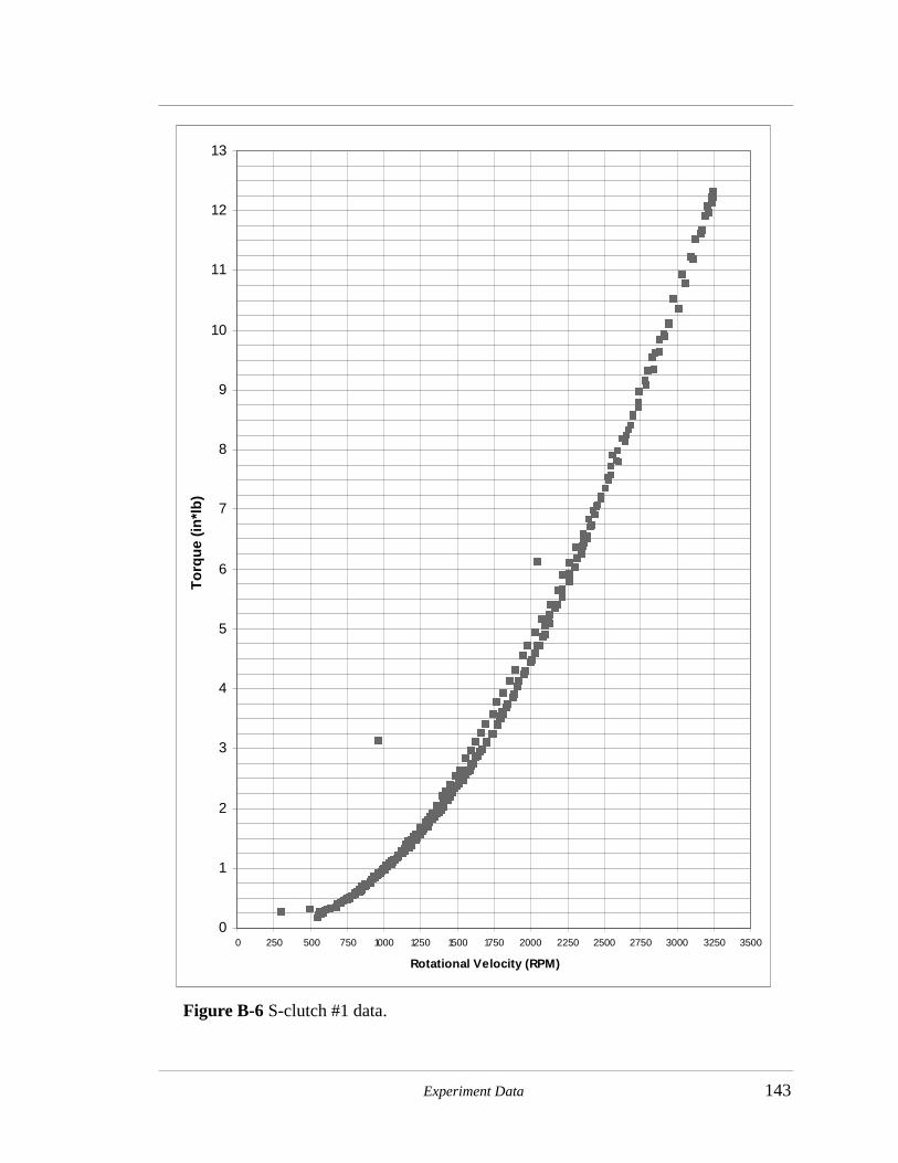
Experiment Data 143
Figure B-6 S-clutch #1 data.
0
1
2
3
4
5
6
7
8
9
10
11
12
13
0 250 500 750 1000 1250 1500 1750 2000 2250 2500 2750 3000 3250 3500
Rotational Velocity (RPM)
To
rqu
e (i
n*l
b)
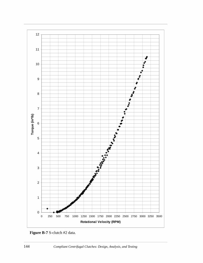
144 Compliant Centrifugal Clutches: Design, Analysis, and Testing
Figure B-7 S-clutch #2 data.
0
1
2
3
4
5
6
7
8
9
10
11
12
0 250 500 750 1000 1250 1500 1750 2000 2250 2500 2750 3000 3250 3500
Rotational Velocity (RPM)
To
rqu
e (i
n*l
b)

Experiment Data 145
0
1
2
3
4
5
6
7
8
9
10
11
12
13
14
15
16
0 250 500 750 1000 1250 1500 1750 2000 2250 2500 2750 3000 3250 3500
Rotational Velocity (RPM)
To
rqu
e (i
n*l
b)
Figure B-8 F1 clutch #1 data from two speed cycles.
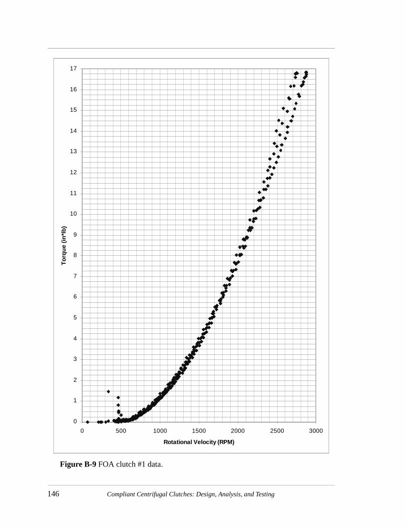
146 Compliant Centrifugal Clutches: Design, Analysis, and Testing
0
1
2
3
4
5
6
7
8
9
10
11
12
13
14
15
16
17
0 500 1000 1500 2000 2500 3000
Rotational Velocity (RPM)
To
rqu
e (i
n*l
b)
Figure B-9 FOA clutch #1 data.

Experiment Data 147
0
1
2
3
4
5
6
7
8
9
10
11
12
13
14
15
16
17
18
19
0 500 1000 1500 2000 2500 3000
Rotational Velocity (RPM)
To
rqu
e (i
n*l
b)
Figure B-10 FOA clutch #2 data.

148 Compliant Centrifugal Clutches: Design, Analysis, and Testing
0
1
2
3
4
5
6
7
8
9
10
11
12
13
14
15
16
17
18
19
20
21
22
0 500 1000 1500 2000 2500 3000
Rotational Velocity (rpm)
To
rqu
e (i
n*l
b)
Figure B-11 FOA clutch #3 data.

Experiment Data 149
0
1
2
3
4
5
6
7
8
9
10
11
12
13
14
15
16
17
18
19
20
21
22
23
24
25
26
27
28
29
30
0 500 1000 1500 2000 2500 3000
Rotational Velocity (rpm)
To
rqu
e (i
n*l
b)
Figure B-12 FOA clutch #4 initial results.

150 Compliant Centrifugal Clutches: Design, Analysis, and Testing
set of tests repeatedly recorded torques such as shown in Figure B-13 on page 151 with a
corresponding average torque capacity of 2.66 in*lb/1000 rpm. This value is within nine
percent of the model predictions.
The error is likely due to excessive bearing torque as was measured in Figure B-2
on page 137. A fifth order polynomial was fit to the bearing torque curve shown in Figure
B-2 and subtracted from the torque data shown in Figure B-12 on page 149. The Tb value
calculated from this data is 2.64 in*lb/1000 rpm. This torque capacity is in good
agreement with the second set of torque data. However, only the torque capacities and
engagement speeds from the second set of data were used to calculate the average values
reported in Chapter 5.
B.9 Grounded Opposing Arm (GOA) Clutch
B.9.1 GOA #1Data is shown in Figure B-14 on page 152.
B.9.2 GOA #2Data is shown in Figure B-15 on page 153.
B.10 Split-arm Clutch
B.10.1 Split-arm #1Data is shown in Figure B-16 on page 154.
B.10.2 Split-arm #2Data is shown in Figure B-17 on page 155.

Experiment Data 151
0
1
2
3
4
5
6
7
8
9
10
11
12
13
14
15
16
17
18
19
20
21
22
23
24
25
26
27
0 500 1000 1500 2000 2500 3000
Rotational Velocity (rpm)
To
rqu
e (i
n*l
b)
Figure B-13 FOA clutch #4 secondary results.

152 Compliant Centrifugal Clutches: Design, Analysis, and Testing
0
1
2
3
4
5
6
7
8
9
10
11
12
13
14
15
16
17
0 500 1000 1500 2000 2500 3000
Rotational Velocity (rpm)
To
rqu
e (i
n*l
b)
Figure B-14 GOA clutch #1 data.

Experiment Data 153
0
1
2
3
4
5
6
7
8
9
10
11
12
13
14
0 500 1000 1500 2000 2500 3000
Rotational Velocity (rpm)
To
rqu
e (i
n*l
b)
Figure B-15 GOA clutch #2 data.

154 Compliant Centrifugal Clutches: Design, Analysis, and Testing
0
1
2
3
4
5
6
7
8
9
10
11
12
0 500 1000 1500 2000 2500 3000
Rotational Velocity (rpm)
To
rqu
e (i
n*l
b)
Figure B-16 Split-arm clutch #1 data.

Experiment Data 155
0
1
2
3
4
5
6
7
8
9
10
0 500 1000 1500 2000 2500 3000
Rotational Velocity (rpm)
To
rqu
e (i
n*l
b)
Figure B-17 Split-arm clutch #2 data.
156 Compliant Centrifugal Clutches: Design, Analysis, and Testing
B.10.3 Split-arm #3Data is shown in Figure B-18 on page 157.
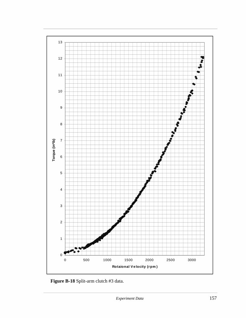
Experiment Data 157
0
1
2
3
4
5
6
7
8
9
10
11
12
13
0 500 1000 1500 2000 2500 3000
Rotaional V e locity (rpm )
To
rqu
e (i
n*l
b)
Figure B-18 Split-arm clutch #3 data.

158 Compliant Centrifugal Clutches: Design, Analysis, and Testing