comparision between manual analysis and …dsresearchcenter.net/pdf/v2_i17/v2-i17-2.pdf · the...
TRANSCRIPT
DURGA RAO U, et al, International Journal of Research Sciences and Advanced Engineering [IJRSAE]TM Volume 2, Issue 17, PP: 14 - 22, JAN - MAR’ 2017.
International Journal of Research Sciences and Advanced Engineering
Vol.2 (17), ISSN: 2319-6106, JAN - MAR’ 2017. PP: 14 - 22
COMPARISION BETWEEN MANUAL ANALYSIS AND STAAD PRO.
ANALYSIS OF MULTI STOREY BUILDING
U DURGA RAO 1*, B BEERAIAH 2*, M V NARASAIAH 3*, Dr. Y RAMESH BABU 4*
1. Student, Dept of CIVIL, VELAGA NAGESWARA RAO COLLEGE OF ENGINEERING. 2. Dept of CIVIL, VELAGA NAGESWARA RAO COLLEGE OF ENGINEERING.
3. HEAD-Dept of CIVIL - VELAGA NAGESWARA RAO COLLEGE OF ENGINEERING. 4. Principal - VELAGA NAGESWARA RAO COLLEGE OF ENGINEERING.
ABSTRACT
The principle objective of this project is to analyze and design a multi-storeyed building [G + 2 (3
dimensional frame)] using STAAD Pro. The design involves load calculations manually and analyzing
the whole structure by STAAD Pro. The design methods used in STAAD-Pro analysis are Limit State
Design conforming to Indian Standard Code of Practice.
STAAD.Pro is the professional’s choice. Initially we started with the analysis of simple 2
dimensional frames and manually checked the accuracy of the software with our results. The results
proved to be very accurate. We analyzed and designed a G + 2 storey building [2-D Frame] initially for
all possible load combinations dead, live, wind and seismic loads]. STAAD.Pro has a very interactive
user interface which allows the users to draw the frame and input the load values and dimensions. Then
according to the specified criteria assigned it analyses the structure and designs the members with
reinforcement details for RCC frames. We continued with our work with some more multi-storeyed 2-D
and 3-D frames under various load combinations. Our final work was the proper analysis and design of a
G + 2 3-D RCC frame under various load combinations.
The materials were specified and cross-sections of the beam and column members were
assigned. The supports at the base of the structure were also specified as fixed. The codes of practice to be
followed were also specified for design purpose with other important details. Then STAAD.Pro was used
to analyze the structure and design the members.
INTRODUCTION
Buildings constitute a part of the definition of
civilizations, a way of life advanced by the
people. The construction of buildings should be
looked upon as a process responded to human
requirements rather than as a product to be
designed and built a great expense.
A building is a structure with a roof and walls
standing more or less permanently in one place,
such as a house or factory. Buildings come in a
variety of sizes, shapes and functions, and have
been adapted throughout history for a wide
number of factors, from building materials
available, to weather conditions, to land prices,
ground conditions, specific uses and aesthetic
reasons. To better understand the term building
compares the list of non-building structures.
Buildings serve several needs of society –
primarily as shelter from weather, security,
living space, privacy, to store belongings, and to

DURGA RAO U, et al, International Journal of Research Sciences and Advanced Engineering [IJRSAE]TM Volume 2, Issue 17, PP: 14 - 22, JAN - MAR’ 2017.
International Journal of Research Sciences and Advanced Engineering
Vol.2 (17), ISSN: 2319-6106, JAN - MAR’ 2017. PP: 14 - 22
comfortably live and work. A building as a
shelter represents a physical division of the
human habitat (a place of comfort and safety)
and the outside (a place that at times may be
harsh and harmful).
Ever since the first cave paintings, buildings
have also become objects or canvases of artistic
expression. In recent years, interest in
sustainable planning and building practices has
also become an intentional part of the design
process of many new buildings.
Single-family residential buildings are most
often called houses or homes. Residential
buildings containing more than one dwelling
unit are called a duplex, apartment building to
differentiate them from 'individual' houses. A
condominium is an apartment that the occupant
owns rather than rents. Houses may also be built
in pairs (semi-detached), in terraces where all
but two of the houses have others either side;
apartments may be built round courtyards or as
rectangular blocks surrounded by a piece of
ground of varying sizes. Houses which were
built as a single dwelling may later be divided
into apartments or bedsitters; they may also be
converted to another use e.g. an office or a shop.
Building types may range from huts to multi-
million dollar high-rise apartment blocks able to
house thousands of people. Increasing settlement
density in buildings (and smaller distances
between buildings) is usually a response to high
ground prices resulting from many people
wanting to live close to work or similar
attractors. Other common building materials are
brick, concrete or combinations of either of
these with stone The dimensions of the interior
rooms are fixed as per the guidelines of national
building code. Each that is provided with all the
basic amenities and requirements like bedroom
with attached bath, a living cum dining room
and a kitchen, as described above. Sufficiently
large doors and windows in good number are
provided for better ventilation. A special feature
of this building is the provision of ventilation
from all sides as possible i.e., from bath rooms
and bed rooms. Each flat has got main entrance
from a common entrance lobby thus take care
not to isolate any flat as a protection against
burglary at the same time maintaining sufficient
privacy. The building is provided with a
spacious staircase to avoid over – crowding.
The building is designed as a framed structure
with brick walls as infill walls. All the exterior
walls are one brick-wall while all the partition
walls are half brick walls. We propose use M20
concrete and Fe415 bars for all structural
components like slabs, beams columns and
Foundation.
Regarding their structural features, they are
rectangular buildings. All the columns are
arranged in such a way that they form typical
frames in length and width direction. The
longitudinal and transverse frames are
analyzed using the Kani‘s method of
analysis. The limit state method of collapse
using IS: 456-2000, and SP-16 have been
adopted for the design of all structural
components like slabs, beams, columns and
foundations.
We have compared the manual analysis results
with the results obtained by using the STAAD
Pro. Software. We have used the AUTO CAD
for effective representation of the plans.

DURGA RAO U, et al, International Journal of Research Sciences and Advanced Engineering [IJRSAE]TM Volume 2, Issue 17, PP: 14 - 22, JAN - MAR’ 2017.
International Journal of Research Sciences and Advanced Engineering
Vol.2 (17), ISSN: 2319-6106, JAN - MAR’ 2017. PP: 14 - 22
Fig: Plan
LOAD CALCULATIONS
Loads considered:
Dead loads: (from IS-875 part 1)
1. Unit weight of concrete 25kN/m3
2. Unit weight of brick work 19.1kN/m3
3.Floor finishes 1.5 kN/m2
Live loads: (from IS-875 part 2) from Table 1
1.All rooms and kitchens 2 kN/m2
2.Toilet and bathrooms 2 kN/m2
3.Corridor, passages, Stair case, Including tire
escapes and store rooms 3 kN/m2
4.Balconies 3 kN/m2
5.On to the roof(from table 2:access provided)
1.5 kN/m2
STRUCTURAL ANALYSIS:
INTRODUCTION:
Structural analysis deals with the behavior of
structure in the given loading conditions.
Depending upon the nature of loading, the
structure may respond in number of ways. The
structure may deform statistically, might yield
and may vibrate or buckle. Structures carrying
static loading can be classified as statically
determinate and statically indeterminate
structure. If all reactions and internal forces in a
structure can be found using the equilibrium
conditions along that is,
∑Fx =0, ∑Fy =0, ∑Fz=0, ∑My =0, ∑Mz =0.
Then the structure is statically determinate, if
not it is statically indeterminate of redundant
various methods popularly used for analysis
includes
Moment distribution method
DURGA RAO U, et al, International Journal of Research Sciences and Advanced Engineering [IJRSAE]TM Volume 2, Issue 17, PP: 14 - 22, JAN - MAR’ 2017.
International Journal of Research Sciences and Advanced Engineering
Vol.2 (17), ISSN: 2319-6106, JAN - MAR’ 2017. PP: 14 - 22
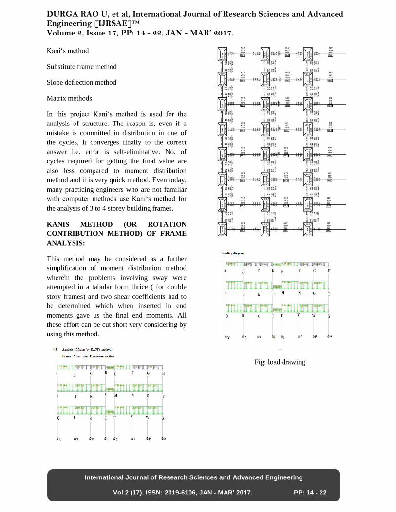
Kani‘s method
Substitute frame method
Slope deflection method
Matrix methods
In this project Kani‘s method is used for the
analysis of structure. The reason is, even if a
mistake is committed in distribution in one of
the cycles, it converges finally to the correct
answer i.e. error is self-eliminative. No. of
cycles required for getting the final value are
also less compared to moment distribution
method and it is very quick method. Even today,
many practicing engineers who are not familiar
with computer methods use Kani‘s method for
the analysis of 3 to 4 storey building frames.
KANIS METHOD (OR ROTATION
CONTRIBUTION METHOD) OF FRAME
ANALYSIS:
This method may be considered as a further
simplification of moment distribution method
wherein the problems involving sway were
attempted in a tabular form thrice ( for double
story frames) and two shear coefficients had to
be determined which when inserted in end
moments gave us the final end moments. All
these effort can be cut short very considering by
using this method.
Fig: load drawing
DURGA RAO U, et al, International Journal of Research Sciences and Advanced Engineering [IJRSAE]TM Volume 2, Issue 17, PP: 14 - 22, JAN - MAR’ 2017.
International Journal of Research Sciences and Advanced Engineering
Vol.2 (17), ISSN: 2319-6106, JAN - MAR’ 2017. PP: 14 - 22
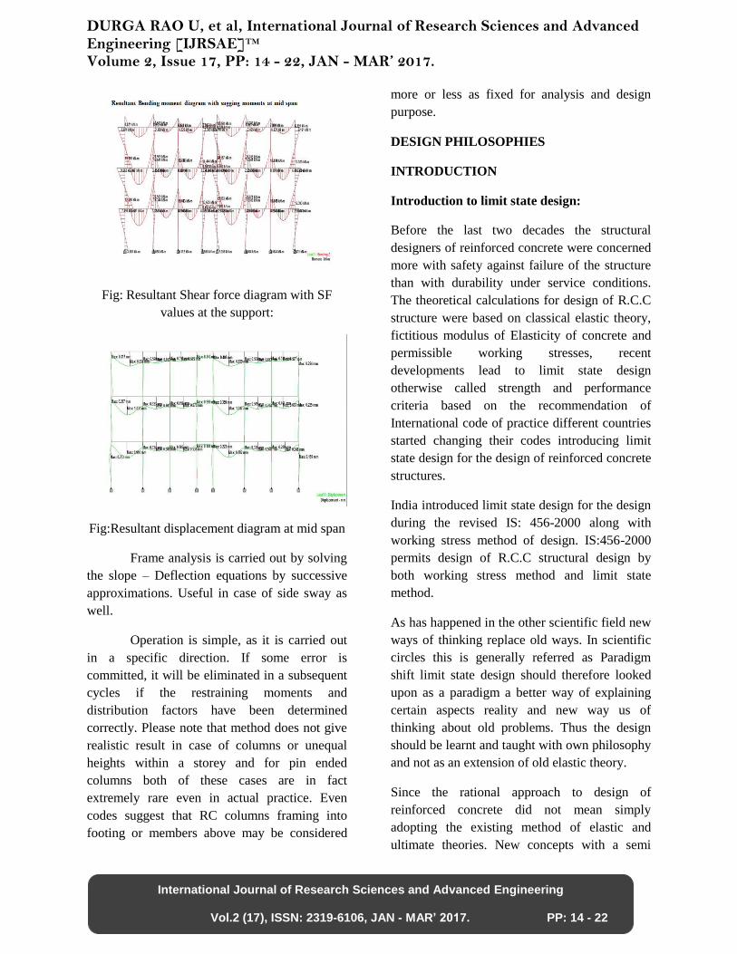
Fig: Resultant Shear force diagram with SF
values at the support:
Fig:Resultant displacement diagram at mid span
Frame analysis is carried out by solving
the slope – Deflection equations by successive
approximations. Useful in case of side sway as
well.
Operation is simple, as it is carried out
in a specific direction. If some error is
committed, it will be eliminated in a subsequent
cycles if the restraining moments and
distribution factors have been determined
correctly. Please note that method does not give
realistic result in case of columns or unequal
heights within a storey and for pin ended
columns both of these cases are in fact
extremely rare even in actual practice. Even
codes suggest that RC columns framing into
footing or members above may be considered
more or less as fixed for analysis and design
purpose.
DESIGN PHILOSOPHIES
INTRODUCTION
Introduction to limit state design:
Before the last two decades the structural
designers of reinforced concrete were concerned
more with safety against failure of the structure
than with durability under service conditions.
The theoretical calculations for design of R.C.C
structure were based on classical elastic theory,
fictitious modulus of Elasticity of concrete and
permissible working stresses, recent
developments lead to limit state design
otherwise called strength and performance
criteria based on the recommendation of
International code of practice different countries
started changing their codes introducing limit
state design for the design of reinforced concrete
structures.
India introduced limit state design for the design
during the revised IS: 456-2000 along with
working stress method of design. IS:456-2000
permits design of R.C.C structural design by
both working stress method and limit state
method.
As has happened in the other scientific field new
ways of thinking replace old ways. In scientific
circles this is generally referred as Paradigm
shift limit state design should therefore looked
upon as a paradigm a better way of explaining
certain aspects reality and new way us of
thinking about old problems. Thus the design
should be learnt and taught with own philosophy
and not as an extension of old elastic theory.
Since the rational approach to design of
reinforced concrete did not mean simply
adopting the existing method of elastic and
ultimate theories. New concepts with a semi
DURGA RAO U, et al, International Journal of Research Sciences and Advanced Engineering [IJRSAE]TM Volume 2, Issue 17, PP: 14 - 22, JAN - MAR’ 2017.
International Journal of Research Sciences and Advanced Engineering
Vol.2 (17), ISSN: 2319-6106, JAN - MAR’ 2017. PP: 14 - 22
probabilistic approach to design were found
necessary the proposed new method had to
provide a framework, which would allow a
design to be economical and safe. The new
philosophy of design was called the limit state
method of design
CONCEPT OF LIMIT STATES
In the method of design based on limit state
concepts the structure shall be designed to
withstand safely all loads to act on it throughout
its life, it shall also satisfy the serviceability
requirements such as limitations on deflection
and cracking. The acceptable limit for the safety
and serviceability requirements before failure
occurs is called limit state. The aim of the design
is to achieve acceptable probabilities that the
structure will not become unfit for the use for
which it is intended, i.e., that it will not reach a
limit state.
All relevant limit state shall be considered in
design to ensure an adequate degree of safety
and serviceability. In general the structure shall
be designed on the basis of the most critical limit
state and shall be checked for other limit states.
For ensuring above objective, the design should
be based on characteristic values for material
strengths and in the loads to be supported, the
characteristic values should be based on
statistical data; if available where such data are
not available they should be based on
experience. The design values are derived from
the characteristic values through the use of
partial safely factors, one for material strengths
and other for load. In the absence of special
consideration these factors have values given in
IS: 456 – 2000 according to the material the type
of loading and the limit state being considered.
PARTIAL SAFETY FACTORS
Ultimate load theory is based on the assumption
that a structure reaches a collapse condition
forming a mechanism when a certain load is
applied. The load factor has been judiciously
selected giving due considerations to the various
factors contributing the failure. The load factor
is used in estimating ultimate loading.
Partial safety factor for material, strength should
account for,
•Possibility of deviation of the strength of
material.
•Deviation of structural dimensions.
•Deviation of structural dimensions.
•Accuracy of the calculations procedure.
•Risk to like and economic consequences.
When assuming the strength of a structure for
limit state of collapse. Value of partial safety
factors should be taken into account for,
Partial safety factor for concrete = 1.5
Partial safety factor for steel = 1.15
Partial safety factors for loads should account
for
•Unusual increasing loads beyond that using for
deriving characteristic values.
•Unforeseen stress distribution. \
•In accurate assessment of the effect of loading.
Partial safely factors of loads under different
conditions are given in clause 35.4 of IS: 456 –
2000.
SLAB DESIGN

DURGA RAO U, et al, International Journal of Research Sciences and Advanced Engineering [IJRSAE]TM Volume 2, Issue 17, PP: 14 - 22, JAN - MAR’ 2017.
International Journal of Research Sciences and Advanced Engineering
Vol.2 (17), ISSN: 2319-6106, JAN - MAR’ 2017. PP: 14 - 22
Fig: slab detailing
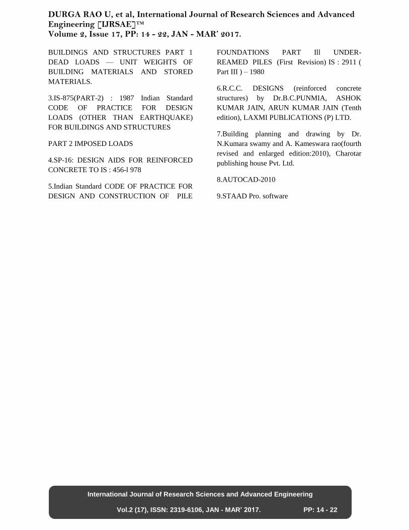
DESIGN OF BEAMS
Column detailing
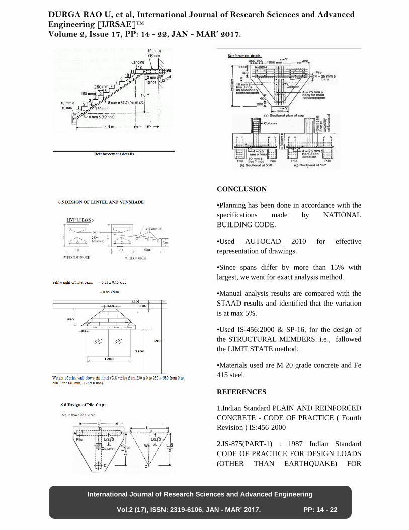
STAIRCASE DETAILING
DURGA RAO U, et al, International Journal of Research Sciences and Advanced Engineering [IJRSAE]TM Volume 2, Issue 17, PP: 14 - 22, JAN - MAR’ 2017.
International Journal of Research Sciences and Advanced Engineering
Vol.2 (17), ISSN: 2319-6106, JAN - MAR’ 2017. PP: 14 - 22
CONCLUSION
•Planning has been done in accordance with the
specifications made by NATIONAL
BUILDING CODE.
•Used AUTOCAD 2010 for effective
representation of drawings.
•Since spans differ by more than 15% with
largest, we went for exact analysis method.
•Manual analysis results are compared with the
STAAD results and identified that the variation
is at max 5%.
•Used IS-456:2000 & SP-16, for the design of
the STRUCTURAL MEMBERS. i.e., fallowed
the LIMIT STATE method.
•Materials used are M 20 grade concrete and Fe
415 steel.
REFERENCES
1.Indian Standard PLAIN AND REINFORCED
CONCRETE - CODE OF PRACTICE ( Fourth
Revision ) IS:456-2000
2.IS-875(PART-1) : 1987 Indian Standard
CODE OF PRACTICE FOR DESIGN LOADS
(OTHER THAN EARTHQUAKE) FOR
DURGA RAO U, et al, International Journal of Research Sciences and Advanced Engineering [IJRSAE]TM Volume 2, Issue 17, PP: 14 - 22, JAN - MAR’ 2017.
International Journal of Research Sciences and Advanced Engineering
Vol.2 (17), ISSN: 2319-6106, JAN - MAR’ 2017. PP: 14 - 22
BUILDINGS AND STRUCTURES PART 1
DEAD LOADS — UNIT WEIGHTS OF
BUILDING MATERIALS AND STORED
MATERIALS.
3.IS-875(PART-2) : 1987 Indian Standard
CODE OF PRACTICE FOR DESIGN
LOADS (OTHER THAN EARTHQUAKE)
FOR BUILDINGS AND STRUCTURES
PART 2 IMPOSED LOADS
4.SP-16: DESIGN AIDS FOR REINFORCED
CONCRETE TO IS : 456-l 978
5.Indian Standard CODE OF PRACTICE FOR
DESIGN AND CONSTRUCTION OF PILE
FOUNDATIONS PART Ill UNDER-
REAMED PILES (First Revision) IS : 2911 (
Part III ) – 1980
6.R.C.C. DESIGNS (reinforced concrete
structures) by Dr.B.C.PUNMIA, ASHOK
KUMAR JAIN, ARUN KUMAR JAIN (Tenth
edition), LAXMI PUBLICATIONS (P) LTD.
7.Building planning and drawing by Dr.
N.Kumara swamy and A. Kameswara rao(fourth
revised and enlarged edition:2010), Charotar
publishing house Pvt. Ltd.
8.AUTOCAD-2010
9.STAAD Pro. software