(cmu) wireless mcu clock management unit an0004.0: …wireless mcu clock management unit (cmu) this...
TRANSCRIPT

AN0004.0: EFM32 Series 0 and EZR32Wireless MCU Clock Management Unit(CMU)
This application note provides an overview of the CMU modulefor EFM32 and EZR32 Wireless MCU Series 0 devices with ex-planations on how to choose clock sources, prescaling, and clockcalibration.It also contains information about how to handle oscillators on wake up, external clocksources, and RC oscillator calibration.
KEY POINTS
• The CMU has several internal clocksources available.
• The CMU can also use external highfrequency and low frequency clocksources.
• Selecting the right clock source is key forcreating low energy applications.
• This application note includes:• This PDF document• Source files
• Example C-code• Multiple IDE projects
CMUOscillators
WDOG clock
LETIMER clock
LCD clock
Peripheral A clock
Peripheral B clock
Peripheral C clock
Peripheral D clock
CPU clock
silabs.com | Building a more connected world. Rev. 1.10

1. Device Compatibility
This application note supports multiple device families, and some functionality is different depending on the device.
EFM32 Series 0 consists of:• EFM32 Gecko (EFM32G)• EFM32 Giant Gecko (EFM32GG)• EFM32 Wonder Gecko (EFM32WG)• EFM32 Leopard Gecko (EFM32LG)• EFM32 Tiny Gecko (EFM32TG)• EFM32 Zero Gecko (EFM32ZG)• EFM32 Happy Gecko (EFM32HG)
EZR32 Wireless MCU Series 0 consists of:• EZR32 Wonder Gecko (EZR32WG)• EZR32 Leopard Gecko (EZR32LG)• EZR32 Happy Gecko (EZR32HG)
AN0004.0: EFM32 Series 0 and EZR32 Wireless MCU Clock Management Unit (CMU)Device Compatibility
silabs.com | Building a more connected world. Rev. 1.10 | 2

2. Functional Description
The Clock Management Unit (CMU) controls the oscillators and clocks. It can enable or disable the clock to the different peripheralsindividually, as well as enable, disable, or configure the available oscillators. This allows for minimizing energy consumption by disa-bling the clock for unused peripherals or having them run at lower frequencies.
AN0004.0: EFM32 Series 0 and EZR32 Wireless MCU Clock Management Unit (CMU)Functional Description
silabs.com | Building a more connected world. Rev. 1.10 | 3

2.1 Clock Branches
The CMU main and sub clock branches are described in table below. Some peripherals have dedicated prescalers, such as the LowEnergy peripherals. Other peripherals need to be prescaled by prescaling their clock source, which will affect all the peripherals drivenby that same source.
For a detailed diagram (CMU Overview) on a given device’s clock tree, please refer to the device reference manual.
Table 2.1. Clock Branches
Main Clock Branch1 Clock Source2 Sub-clock Branch 11 Sub-clock Branch 21
HFCLK • HFRCO• HFXO• LFRCO• LFXO• USHFRCO/1 or /2
HFPERCLK • ACMP0, ACMP1• ADC0• DAC0• GPIO• IDAC0• I2C0, I2C1• PRS• TIMER0, TIMER1, TIMER2,
TIMER3• UART0, UART1• USART0, USART1, USART2• VCMP
HFCORECLK • CORTEX (Core)• AES• DMA• EBI• LE• USB• USBC
DBGCLK —
HFCORECLKUSBC • Undivided HFCLK• LFRCO• LFXO• USHFRCO
— —
AUXCLK AUXHFRCO DBGCLK —
LESENSE —
MSC —
LFACLK • HFCORECLKLE/2 orHFCORECLKLE/43
• LFRCO• LFXO• ULFRCO
• LCD• LESENSE• LETIMER0• PCNT0, PCNT1, PCNT2• RTC
—
LFBCLK • HFCORECLKLE/2 orHFCORECLKLE/43
• LFRCO• LFXO• ULFRCO
• LEUART0• LEUART1
—
AN0004.0: EFM32 Series 0 and EZR32 Wireless MCU Clock Management Unit (CMU)Functional Description
silabs.com | Building a more connected world. Rev. 1.10 | 4

Main Clock Branch1 Clock Source2 Sub-clock Branch 11 Sub-clock Branch 21
LFCCLKUSBLE • LFRCO• LFXO
— —
WDOGCLK • LFRCO• LFXO• ULFRCO
WDOG —
BURTC • LFRCO• LFXO• ULFRCO
— —
Note:1. Not all main and sub clock branches are available on a given device. Refer to the device reference manual and data sheet for
details2. Not all clock sources for main clock branches are available on a given device. Refer to the device reference manual and data
sheet for details.3. The HFCORECLKLE/4 is not available on EFM32 Gecko (EFM32G) and EFM32 Tiny Gecko (EFM32TG) devices.
AN0004.0: EFM32 Series 0 and EZR32 Wireless MCU Clock Management Unit (CMU)Functional Description
silabs.com | Building a more connected world. Rev. 1.10 | 5

2.2 Clock Sources
There are a maximum of seven oscillators that can be used as clock sources for different purposes. The HFCLK is usually clocked byHFXO, HFRCO, or USHFRCO, whereas low energy peripherals are usually clocked by LFXO, LFRCO, or ULFRCO. The AUXHFRCOis used for LESENSE, flash programming, and SWO debug output.
Table 2.2. Clock Sources
Oscillator Frequency Range
HFXO 4 – 48 MHz
HFRCO 1 – 28 MHz
AUXHFRCO 1 – 28 MHz
USHFRCO1 24 or 48 MHz
LFXO 32768 Hz
LFRCO 32768 Hz
ULFRCO 1000 Hz
Note:1. The USHFRCO is only available on EFM32 and EZR32 Happy Gecko (EFM32HG and EZR32HG) devices.
To select the clock source for a branch (e.g. HFCLK, LFA, or LFB), the chosen oscillator must be enabled before it is selected as theclock source. If this is not done, the modules that are running from that clock branch will stop. In the case of selecting a disabled oscilla-tor for the HFCLK branch, the CPU will stop and can only be recovered after a reset.
After a reset, the HFCLK branch is clocked by the HFRCO at the default 14 MHz frequency band, and all low frequency branches havethe LFRCO selected as their clock source. The LFRCO is disabled upon reset, so it needs to be enabled before using the low frequen-cy peripherals.
EMLIB has functions to enable or disable an oscillator and select it as a clock source.
Table 2.3. The emlib Functions for Oscillator Enable, Disable and Selection
emlib Function Usage Example
CMU_OscillatorEnable(CMU_Osc_TypeDe
f osc, bool enable, bool wait)
Select which oscillator to enable or disableand if it should wait for the oscillator to sta-bilize before returning.
Enable HFXO and wait for it to stabilize:CMU_OscillatorEnable (cmuOsc_HFXO,
true, true);
Disable HFRCO:CMU_OscillatorEnable (cmuOsc_HFRCO,
false, false);
CMU_ClockSelectSet(CMU_Clock_TypeDe
f clock, CMU_Select_TypeDef ref)
• Enables the chosen clock source incase it has not been enabled yet.
• The clock parameter is one of the mainclock branches, and the ref is one ofthe clock sources for the selected clockbranch.
Select HFXO as the source of HFCLK:CMU_ClockSelectSet (cmuClock_HF, cm
uSelect_HFXO);
Select USHFRCODIV2 as the source ofHFCLK:CMU_ClockSelectSet(cmuClock_HF, cmu
Select_USHFRCODIV2);
Select LFXO as the source of LFACLK:CMU_ClockSelectSet(cmuClock_LFA, cm
uSelect_LFXO);
AN0004.0: EFM32 Series 0 and EZR32 Wireless MCU Clock Management Unit (CMU)Functional Description
silabs.com | Building a more connected world. Rev. 1.10 | 6

2.3 Oscillator Configuration
2.3.1 HFXO
The High Frequency Crystal Oscillator (HFXO) is configured to ensure safe startup and operation for most common crystals by default.In order to optimize startup time and power consumption for a given crystal, it is possible to adjust certain oscillator parameters. Formore information, refer to application note, AN0016: Oscillator Design Considerations.
The HFXO gain can be increased by setting HFXOBOOST bitfield in the CMU_CTRL register. The HFXOBUFCUR bitfield in theCMU_CTRL register should be set to BOOSTABOVE32MHZ when operating above 32 MHz. When operating at 32 MHz or below, thedefault value (BOOSTUPTO32MHZ) should be used. It is important that the boost settings, along with the crystal load capacitors, arematched to the crystal in use.
Note: The BOOSTABOVE32MHZ is only available on EFM32GG, EFM32LG, EFM32WG, EZR32LG, and EZR32WG devices.
Table 2.4. HFXO Frequency Range
Device HFXO Frequency Range
EFM32ZG 4 – 24 MHz
EFM32HG and EZR32HG 4 – 25 MHz
EFM32G and EFM32TG 4 – 32 MHz
EFM32GG, EFM32LG, EFM32WG, EZR32LG, and EZR32WG 4 – 48 MHz
2.3.1.1 The emlib Function for HFXO Configuration
To simplify the HFXO configuration, emlib contains structures and functions which will properly configure the HFXO for efficient opera-tion. It is strongly recommended to take advantage of these structures and functions. These emlib functions will also avoid or work-around any errata issues affecting the HFXO configuration.
The HFXO initialization structure of type CMU_HFXOInit_TypeDef:
typedef struct{#if defined( _CMU_HFXOCTRL_MASK ) bool lowPowerMode; /**< Enable low-power mode */ bool autoStartEm01; /**< @deprecated Use @ref CMU_HFXOAutostartEnable instead. */ bool autoSelEm01; /**< @deprecated Use @ref CMU_HFXOAutostartEnable instead. */ bool autoStartSelOnRacWakeup; /**< @deprecated Use @ref CMU_HFXOAutostartEnable instead. */ uint16_t ctuneStartup; /**< Startup phase CTUNE (load capacitance) value */ uint16_t ctuneSteadyState; /**< Steady-state phase CTUNE (load capacitance) value */ uint8_t regIshSteadyState; /**< Shunt steady-state current */ uint8_t xoCoreBiasTrimStartup; /**< Startup XO core bias current trim */ uint8_t xoCoreBiasTrimSteadyState; /**< Steady-state XO core bias current trim */ uint8_t thresholdPeakDetect; /**< Peak detection threshold */ uint8_t timeoutShuntOptimization; /**< Timeout - shunt optimization */ uint8_t timeoutPeakDetect; /**< Timeout - peak detection */ uint8_t timeoutSteady; /**< Timeout - steady-state */ uint8_t timeoutStartup; /**< Timeout - startup */#else uint8_t boost; /**< HFXO Boost, 0=50% 1=70%, 2=80%, 3=100% */ uint8_t timeout; /**< Startup delay */ bool glitchDetector; /**< Enable/disable glitch detector */#endif CMU_OscMode_TypeDef mode; /**< Oscillator mode */} CMU_HFXOInit_TypeDef;
AN0004.0: EFM32 Series 0 and EZR32 Wireless MCU Clock Management Unit (CMU)Functional Description
silabs.com | Building a more connected world. Rev. 1.10 | 7

The structure members can be defined by the user; otherwise the default structures CMU_HFXOINIT_DEFAULT and CMU_HFXOINIT_EXTERNAL_CLOCK below can be used as a template for HFXO initialization.
#define CMU_HFXOINIT_DEFAULT \{ \ _CMU_CTRL_HFXOBOOST_DEFAULT, /* 100% HFXO boost */ \ _CMU_CTRL_HFXOTIMEOUT_DEFAULT, /* 16k startup delay */ \ false, /* Disable glitch detector */ \ cmuOscMode_Crystal, /* Crystal oscillator */ \}#define CMU_HFXOINIT_EXTERNAL_CLOCK \{ \ 0, /* Minimal HFXO boost, 50% */ \ _CMU_CTRL_HFXOTIMEOUT_8CYCLES, /* Minimal startup delay, 8 cycles */ \ false, /* Disable glitch detector */ \ cmuOscMode_External, /* External digital clock */ \}
The HFXO initialization structure is used as an argument when calling the CMU_HFXOInit(const CMU_HFXOInit_TypeDef *hfxoInit)function. At the completion of this function call, the related registers for HFXO initialization are configured, HFXO can now be enabledand setup as source of HFCLK as below.
/* Initialize HFXO with specific parameters */CMU_HFXOInit_TypeDef hfxoInit = CMU_HFXOINIT_DEFAULT;CMU_HFXOInit(&hfxoInit);
/* Enable and set HFXO for HFCLK */CMU_ClockSelectSet(cmuClock_HF, cmuSelect_HFXO);
2.3.2 LFXO
The Low Frequency Crystal Oscillator (LFXO) is configured to ensure safe startup and operation for most common crystals by default.In order to optimize startup time and power consumption for a given crystal, it is possible to adjust certain parameters in the oscillator.For more information, refer to application note, AN0016: Oscillator Design Considerations.
The LFXO gain can be increased by setting LFXOBOOST bitfield in the CMU_CTRL register or reduced by setting REDLFXOBOOSTbitfield in the EMU_AUXCTRL register. It is important that the boost settings, along with the crystal load capacitors, are matched to thecrystal in use.
Note: The REDLFXOBOOST bitfield is only available on EFM32 Giant Gecko devices (EFM32GG).
AN0004.0: EFM32 Series 0 and EZR32 Wireless MCU Clock Management Unit (CMU)Functional Description
silabs.com | Building a more connected world. Rev. 1.10 | 8

2.3.2.1 The emlib Function for LFXO Configuration
To simplify the LFXO configuration, emlib contains structures and functions which will properly configure the LFXO for efficient opera-tion.
The LFXO initialization structure of type CMU_LFXOInit_TypeDef:
typedef struct{#if defined( _CMU_LFXOCTRL_MASK ) uint8_t ctune; /**< CTUNE (load capacitance) value */ uint8_t gain; /**< Gain / max startup margin */#else CMU_LFXOBoost_TypeDef boost; /**< LFXO boost */#endif uint8_t timeout; /**< Startup delay */ CMU_OscMode_TypeDef mode; /**< Oscillator mode */} CMU_LFXOInit_TypeDef;
The structure members can be defined by the user; otherwise the default structures CMU_LFXOINIT_DEFAULT and CMU_LFXOINIT_EXTERNAL_CLOCK below can be used as a template for LFXO initialization.
#define CMU_LFXOINIT_DEFAULT \ { \ cmuLfxoBoost70, \ _CMU_CTRL_LFXOTIMEOUT_DEFAULT, \ cmuOscMode_Crystal, \ }#define CMU_LFXOINIT_EXTERNAL_CLOCK \ { \ cmuLfxoBoost70, \ _CMU_CTRL_LFXOTIMEOUT_8CYCLES, \ cmuOscMode_External, \ }
The LFXO initialization structure is used as an argument when calling the CMU_LFXOInit(const CMU_LFXOInit_TypeDef *lfxoInit)function. At the completion of this function call, the related registers for LFXO initialization are configured, and the LFXO can now beenabled and setup as clock source of low energy peripherals.
/* Initialize LFXO with specific parameters */CMU_LFXOInit_TypeDef lfxoInit = CMU_LFXOINIT_DEFAULT;CMU_LFXOInit(&lfxoInit);
/* Enable and set LFXO for LFACLK */CMU_ClockSelectSet(cmuClock_LFA, cmuSelect_LFXO);
AN0004.0: EFM32 Series 0 and EZR32 Wireless MCU Clock Management Unit (CMU)Functional Description
silabs.com | Building a more connected world. Rev. 1.10 | 9

2.3.3 HFRCO, AUXHFRCO, and USHFRCO
By default, the HFRCO and AUXHFRCO band are set to 14 MHz. It can be changed to other preset frequencies using the BAND bitfieldin the CMU_HFRCOCTRL or CMU_AUXHFRCOCTRL register.
The frequency band (24 or 48 MHz) of USHFRCO in the EFM32HG and EZR32HG devices can be changed by using BAND bitfield inthe CMU_USHFROCONF register. When switching frequency bands or enabling/disabling the USHFRCO clock divider (default is ena-bled — USHFRCODIV2DIS bitfield in the CMU_USHFROCONF register is clear), the USHFRCO should not be selected as the clocksource for HFCLK or USBC.
Table 2.5. High Frequency RC Oscillator Band Selection
Oscillator Frequency Band
AUXHFRCO1 • 1 MHz• 7 MHz• 11 MHz• 14 MHz (Default)• 21 MHz• 28 MHz2
HFRCO • 1 MHz• 7 MHz• 11 MHz• 14 MHz (Default)• 21 MHz• 28 MHz2
USHFRCO3 • 24 MHz (Default frequency for device without USB function)• 48 MHz (Default frequency for device with USB function)
Note:1. The AUXHFRCO band frequency selection is not available on EFM32 Gecko (EFM32G) devices. The AUXHFRCO frequency is
fixed at 14 MHz.2. The 28 MHz frequency band is not available on EFM32 Happy Gecko (EFM32HG), Zero Gecko (EFM32ZG), and EZR32 Happy
Gecko (EZR32HG) devices.3. The USHFRCO is only available on EFM32 and EZR32 Happy Gecko (EFM32HG and EZR32HG) devices.
The tuning value for each band of HFRCO, AUXHFRCO, and USHFRCO is set using the TUNING bitfield in the CMU_HFRCOCTRL,CMU_AUXHFRCOCTRL, and CMU_USHFRCOCTRL registers. Each band is calibrated during production, and suitable tuning valuesfor each band can be read from the Device Information (DI) page.
The USHFRCO also employs a second register CMU_USHFRCOTUNE with smaller step sizes, allowing for much finer tuning. TheFINETUNING bitfield in this register is modified by the clock recovery hardware when the device is connected to USB to fine-tune theUSHFRCO and keep the frequency constant over voltage and temperature.
To make this task easier, there are also functions available in emlib to change the HFRCO, AUXHFRCO, and USHFRCO band. Thesefunctions handle the band setting with the correct tuning value loaded from the Device Information (DI) page.
Table 2.6. The emlib Functions to Change Internal RC Oscillator Frequency Band
emlib Function Usage Example
CMU_HFRCOBandSet(CMU_HFRCOBand_Type
Def band)
Change HFRCO frequency band. CMU_HFRCOBandSet(cmuHFRCOBand_21MHz);
CMU_AUXHFRCOBandSet(CMU_AUXHFRCOBan
d_TypeDef band)
Change AUXHFRCO frequencyband.
CMU_ AUXHFRCOBandSet(cmuAUXHFRCOBand_7MHz);
CMU_USHFRCOBandSet(CMU_USHFRCOBand_
TypeDef band)
Change USHFRCO frequencyband.
CMU_USHFRCOBandSet(cmuUSHFRCOBand_24MHz);
AN0004.0: EFM32 Series 0 and EZR32 Wireless MCU Clock Management Unit (CMU)Functional Description
silabs.com | Building a more connected world. Rev. 1.10 | 10

2.3.4 LFRCO
It is possible to calibrate the LFRCO to achieve higher accuracy. The frequency is adjusted by changing the TUNING bitfield in theCMU_LFRCOCTRL register. The LFRCO is also calibrated in production, and its TUNING values are set to the correct value duringreset.
2.3.5 ULFRCO
The ULFRCO is always on in EM0, EM1, EM2, and EM3 and cannot be disabled via the CMU_OSCENCMD register. As such, it isalways available as a clock source for many of the peripherals in the low-frequency clock domains. It is not possible to calibrate theULFRCO to achieve higher accuracy.
2.4 Oscillator Start-up Time and Time-Out
The start-up time differs per oscillator, and the usage of an oscillator clock can further be delayed by a time-out. The time-out delays theassertion of the READY signal for oscillators and should allow for enough time for the oscillator to stabilize. The low start-up time valuescan be used for an external clock source of already high quality, while the higher start-up times should be used when the clock signal iscoming directly from a crystal. Some oscillators have a configurable time-out which is set by software in a bitfield of the correspondingregister.
The time-out can be optimized for the chosen crystal (LFXO and HFXO) used in the application. For the other RC oscillators (LFRCO,HFRCO, AUXHFRCO, and ULFRCO), the start-up time is known, and a fixed time-out is used.
Table 2.7. Oscillator Time-out Configuraton
Oscillator Bitfield and Register
LFXO LFXOTIMEOUT bitfield in CMU_CTRL register.
HFXO Bitfields in CMU_CTRL register:• HFXOTIMEOUT• HFXOGLITCHDETEN
LFRCO Start-up time is fixed.
HFRCO Start-up time is fixed.
AUXHFRCO Start-up time is fixed.
ULFRCO Start-up time is fixed.
USHFRCO1 • Minimum startup time is 6 µs.• TIMEOUT bitfield in CMU_USHFRCOCTRL register.
Note:1. The USHFRCO is only available on EFM32 and EZR32 Happy Gecko (EFM32HG and EZR32HG) devices.
AN0004.0: EFM32 Series 0 and EZR32 Wireless MCU Clock Management Unit (CMU)Functional Description
silabs.com | Building a more connected world. Rev. 1.10 | 11

2.4.1 Glitch Detector
When the HFXO starts running, glitches can appear on the oscillator output while it builds up the oscillation. These glitches can befiltered away if the HFXOGLITCHDETEN bitfield in the CMU_CTRL register is enabled. The detector flags all glitches shorter than 1 nsand no glitches longer than 4 ns. The start-up counter is reset each time a glitch is detected.
High frequency glitch
Counter reset
Counter reset
Counter reset
Time
Counter value
Timeout period
HFXORDY is set
Start-up
High frequency glitch
High frequency glitch
Figure 2.1. Glitch Detector
If the glitch detector is enabled, the start-up delay may be longer than the configured HFXOTIMEOUT. This depends on how manyglitches are detected and thus how many times the start-up counter is reset. For optimization purposes, the glitch detector can be ena-bled or disabled while using different timeouts to achieve a faster crystal wake up.
AN0004.0: EFM32 Series 0 and EZR32 Wireless MCU Clock Management Unit (CMU)Functional Description
silabs.com | Building a more connected world. Rev. 1.10 | 12

2.5 Prescaling
There are two sub-branches deriving from the prescaled HFCLK clock branch, HFPERCLK and HFCORECLK, that can be prescaledindividually up to a factor of 512. The HFPERCLK drives the high-frequency peripherals, and the HFCORECLK drives the Core Mod-ules which consist of the CPU and modules tightly coupled to it such as the MSC. Some peripherals allow for even further clock pre-scaling (such as the ADC) which is controlled by the peripheral's registers.
As for the low frequency branches (LFA and LFB), all the peripherals driven from these can be prescaled individually with the exceptionof the Pulse Counter (PCNT).
Table 2.8. Prescaler of Clock Branches
Clock Branch Prescaler Bitfield1 Prescaler Register Prescaler Range
HFCLK HFCLKDIV2 CMU_CTRL 1 to 8
HFPERCLK HFPERCLKDIV CMU_HFPERCLKDIV 20 to 29
HFCORECLK HFCORECLKDIV CMU_HFCORECLKDIV 20 to 29
LFACLK LCD CMU_LFAPRESC0 24 to 27
LESENSE 20 to 23
LETIMER0 20 to 215
RTC 20 to 215
LFBCLK LEUART0 CMU_LFBPRESC0 20 to 23
LEUART1 20 to 23
Note:1. Not all prescaler bitfields are available on a given device. Refer to the device reference manual and data sheet for details.2. The HFCLK prescaler (HFCLKDIV) is not available on EFM32 Gecko (EFM32G), EFM32 Tiny Gecko (EFM32TG), and EFM32
Zero Gecko (EFM32ZG) devices.
The emlib contains a function which can use to prescale the clock source. If setting a low frequency clock prescaler, synchronizationinto the low frequency domain is required.
Table 2.9. The emlib Function to Prescale the Clock Source
emlib Function Usage Example
CMU_ClockDivSet(CMU_Clock_TypeDef c
lock, CMU_ClkDiv_TypeDef div)
For prescaler range is power of 2 HFPERCLK divide by 2 (21):CMU_ClockDivSet(cmuClock_HFPER, cmu
ClkDiv_2);
When using this function some attention should be made to both parameters. Not all clocks have a prescaler and the maximum prescal-ing value is also not the same for the different clocks (for instance the HFPERCLK has a maximum of 512 but the LETIMER0 clock canbe divided by 32768).
AN0004.0: EFM32 Series 0 and EZR32 Wireless MCU Clock Management Unit (CMU)Functional Description
silabs.com | Building a more connected world. Rev. 1.10 | 13

2.6 Flash Wait States
When changing the memory system clock (HFCORECLK) frequency to a value above certain limit, the number of flash-access waitstates must be set to an appropriate value before the frequency switching. This is handled automatically by the CMU functions in theemlib, but if the user wants to do the change by writing directly into the registers, the number of wait states is modified using the MODEbitfield in the MSC_READCTRL register.
Table 2.10. Flash Wait States
Clock Frequency Minimum Flash Wait States
HFCORECLK <= 16 MHz 0
HFCORECLK <= 32 MHz 1
HFCORECLK > 32 MHz 2
The emlib functions below optimize flash access wait-state configuration if the source or frequency of HFCORECLK is changed wheninvoking these functions.• CMU_ClockDivSet(CMU_Clock_TypeDef clock, CMU_ClkDiv_TypeDef div)
• CMU_ClockSelectSet(CMU_Clock_TypeDef clock, CMU_Select_TypeDef ref)
• CMU_HFRCOBandSet(CMU_HFRCOBand_TypeDef band)
AN0004.0: EFM32 Series 0 and EZR32 Wireless MCU Clock Management Unit (CMU)Functional Description
silabs.com | Building a more connected world. Rev. 1.10 | 14

2.7 Low Energy (LE) Peripheral Clock Divider
To use the low energy peripheral modules, the LE interface clock (HFCORECLKLE) must be enabled in addition to the module clock.
The HFCORECLKLEDIV bitfield in the CMU_HFCORECLKDIV register and the HFLE bitfield in the CMU_CTRL register are only re-quired for frequencies above the LE clock maximum frequency to ensure correct operation of LE peripherals. The HFLE is or'ed withHFCORECLKLEDIV, so setting either of these bits will reduce the LE clock frequency.
Table 2.11. Low Energy Peripheral Clock Divider
Device HFCORECLK Maxi-mum
HFCORECLKLEMaximum
HFLE HFCORECLKDIV
EFM32ZG 24 MHz 12 MHz — DIV2 or DIV4 if HFCORECLK<= 24 MHz
• EFM32H• EZR32HG
25 MHz 12 MHz — • DIV2 or DIV4 if HFCOR-ECLK <= 24 MHz
• DIV4 if HFCORECLKLE > 24MHz
EFM32TG 32 MHz 16 MHz — Not available, LE prescaler isfixed at divided by 2.
EFM32G 32 MHz 16 MHz — Not available, LE prescaler isfixed at divided by 2.
• EFM32LG• EZR32LG• EFM32WG• EZR32WG
48 MHz 12 MHz • 0 or 1 if HFCORECLK <= 24MHz
• 1 if HFCORECLK > 24 MHz
• DIV2 or DIV4 if HFCOR-ECLK <= 24 MHz
• DIV4 if HFCORECLKLE > 24MHz
EFM32GG 48 MHz 16 MHz • 0 or 1 if HFCORECLK <= 32MHz
• 1 if HFCORECLK > 32 MHz
• DIV2 or DIV4 if HFCOR-ECLK <= 32 MHz
• DIV4 if HFCORECLKLE > 32MHz
Before going to a high frequency, make sure the registers in the table above have the correct values. When going down in frequency,make sure to keep the registers at the values required by the higher frequency until after the switch completes.
To make this task easier, there is also a function available in the emlib to ensure the registers in the table above have the correct val-ues when enabling the LE clock.
Table 2.12. The emlib Function to Enable a Module Clock
emlib Function Usage Example
CMU_ClockEnable(CMU_Clock_TypeDef c
lock, bool enable)
To enable a module clock. Enable LE clock with correct settings on correspond-ing registers:CMU_ClockEnable(cmuClock_HFLE, true);
AN0004.0: EFM32 Series 0 and EZR32 Wireless MCU Clock Management Unit (CMU)Functional Description
silabs.com | Building a more connected world. Rev. 1.10 | 15

2.8 External Clock Sources
By default, the LFXO and HFXO are started in crystal mode, but it is possible to connect an active external sine wave or square waveclock source to the LFXTAL_N and HFXTAL_N pins of the LFXO and HFXO. See the table below for the register settings, pin usage,and frequency.
Table 2.13. External Clock Source for LFXO and HFXO
External Clock Register Setting, Pin Usage, and Frequency
Sine Wave for LFXO Set LFXOMODE bitfield in CMU_CTRL register to BUFEXTCLK.
Digital Signal for LFXO Set LFXOMODE bitfield in CMU_CTRL register to DIGEXTCLK.
LFXTAL_N Pin External LFXO clock input.
LFXTAL_P Pin Not used, can use as GPIO.
LFXO Frequency 32768 Hz.
Sine Wave for HFXO Set HFXOMODE bitfield in CMU_CTRL register to BUFEXTCLK.
Digital Signal for HFXO Set HFXOMODE bitfield in CMU_CTRL register to DIGEXTCLK.
HFXTAL_N Pin External HFXO clock input.
HFXTAL_P Pin Not used, can use as GPIO.
HFXO Frequency Refer to Table 2.4 HFXO Frequency Range on page 7 for allowable HFXO frequencyrange of external clock sources.
2.8.1 External Sine Wave
An AC-coupled buffer is in series with the input pin (HFXTAL_N or LFXTAL_N), which is suitable for an external sine wave. The sinewave should have a minimum of 200 mV amplitude single-ended.
2.8.2 Digital External Clock
The digital external clock bypasses the oscillator. The signal should be a rail-to-rail square wave with 50% duty cycle.
2.8.3 Duty Cycle
The recommended duty cycle for an external HFXO clock is 46% to 54% for correct operation. The key requirement is the minimumclock low time and minimum clock high time implied by this specification. If the minimum low and high times are not being met, thensetup violations can occur in the digital logic.
The recommendation is that designs obey the 46-54% duty cycle requirement at the frequencies that determine the number of waitstates used, or 16 MHz and 32 MHz.
Table 2.14. External Clock Requirements
Key Frequency Minimum Clock Low/High Time
16 MHz 28.75 ns
32 MHz 14.38 ns
For example, for an 8 MHz external oscillator, the 16 MHz minimum clock low and high times would be met with 23% duty cycle.
AN0004.0: EFM32 Series 0 and EZR32 Wireless MCU Clock Management Unit (CMU)Functional Description
silabs.com | Building a more connected world. Rev. 1.10 | 16

2.9 Output Clock to Pin
It is possible to configure the CMU to output clocks on the CMU_OUT0 and CMU_OUT1 pins. This clock selection is done using theCLKOUTSEL0 and CLKOUTSEL1 bitfields in the CMU_CTRL register. It is also necessary to configure the CMU_OUT0 andCMU_OUT1 pins as outputs.
Note that some clock outputs (e.g. HFXO) can be unstable after startup and should not be output on a pin before their correspondingready flag (e.g. HFXORDY) is set to 1 in the CMU_STATUS register.
Table 2.15. Clock Output on a Pin
Pin Bitfield
CMU_OUT0 CLKOUTSEL0 in CMU_CTRL register:• HFRCO• HFXO• HFCLK2• HFCLK4• HFCLK8• HFCLK16• ULFRCO• AUXHFRCO1
CMU_OUT1 CLKOUTSEL1 in CMU_CTRL register:• LFRCO• LFXO• HFCLK1
• LFXOQ1
• HFXOQ1
• LFRCOQ1
• HFRCOQ1
• AUXHFRCOQ1
• USHFRCO2
Enable CLKOUT0PEN and CLKOUT1PEN in CMU_ROUTE register.
Location LOCATION in CMU_ROUTE register.
Note:1. These options are not available on EFM32 Gecko (EFM32G) devices.2. The option is only available on EFM32 and EZR32 Happy Gecko (EFM32HG and EZR32HG) devices.
2.10 Interrupts
The interrupts generated by the CMU module are combined into one interrupt vector. If CMU interrupts are enabled, an interrupt will bemade if one or more of the interrupt flags in CMU_IF register and their corresponding bits in CMU_IEN register are set.
AN0004.0: EFM32 Series 0 and EZR32 Wireless MCU Clock Management Unit (CMU)Functional Description
silabs.com | Building a more connected world. Rev. 1.10 | 17

3. Energy Modes
3.1 Active Oscillators
The energy mode of the device determines which oscillators are active. In EM0 and EM1, all oscillators can be enabled and used asclock sources. Upon entering EM2, the high frequency oscillators (HFXO, HFRCO, AUXHFRCO, and USHFRCO, if present) shut offautomatically, such that the high frequency peripherals running from them are also effectively shutdown. In EM3, the low frequencyoscillators (LFXO and LFRCO, but not the PLFRCO, if present) also stop, disabling the low frequency peripherals. The ULFRCO isactive in all energy modes down to EM4H and is only disabled in EM4S unless explicitly retained via the RETAINULFRCO bit in theEMU_EM4CTRL register.
The following table summarizes oscillator availability in each energy mode:
Table 3.1. Energy Mode Oscillator Availability
Oscillator Energy Mode
EM0 EM1 EM2 EM3 EM4H EM4S
HFXO Available Available On demand1 On demand1 — —
HFRCO Available Available — — — —
AUXHFRCO Available Available On demand2 On demand2 — —
USHFRCO Available Available — — — —
DPLL Available Available — — — —
LFXO Available Available Available — Available3 Available3
LFRCO Available Available Available — Available4 Available4
PLFRCO Available Available Available Available — —
ULFRCO On On On On On Available5
Note:1. If needed by the PLFRCO for calibration.2. In response to an asynchronous ADC trigger from the PRS.3. If retained by the RETAINLFXO bit in EMU_EM4CTRL.4. If retained by the RETAINLFRCO bit in EMU_EM4CTRL.5. If retained by the RETAINULFRCO bit in EMU_EM4CTRL.
3.2 Wake Up Considerations
3.2.1 Waking up from Low-Energy Modes
All the oscillators are able to run in EM1, so the core wakes up instantly from this energy mode. In EM2 and EM3 the high frequencyoscillators are disabled, and these need to be re-enabled before the core starts running code.
When waking up from EM2 or EM3, the core will run from the HFRCO by default, regardless of which oscillator it was running frombefore entering these energy modes. The HFRCO has a very short wake-up time, and it takes only few microseconds before the CPUstarts running code. The previously-selected HFRCO band is also restored by hardware on wake-up. The core will run the HFRCO atthe default frequency band when waking up from EM4.
Note: Refer to the device-specific data sheet for the wake-up times from each energy mode.
AN0004.0: EFM32 Series 0 and EZR32 Wireless MCU Clock Management Unit (CMU)Energy Modes
silabs.com | Building a more connected world. Rev. 1.10 | 18
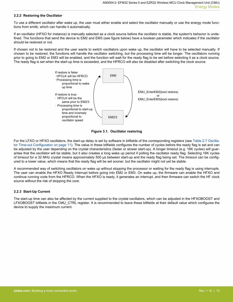
3.2.2 Restoring the Oscillator
To use a different oscillator after wake up, the user must either enable and select the oscillator manually or use the energy mode func-tions from emlib, which can handle it automatically.
If an oscillator (HFXO for instance) is manually selected as a clock source before the oscillator is stable, the system's behavior is unde-fined. The functions that send the device to EM2 and EM3 (see figure below) have a boolean parameter which indicates if the oscillatorshould be restored or not.
If chosen not to be restored and the user wants to switch oscillators upon wake up, the oscillator will have to be selected manually. Ifchosen to be restored, the functions will handle the oscillator switching, but the processing time will be longer. The oscillators runningprior to going to EM2 or EM3 will be enabled, and the function will wait for the ready flag to be set before selecting it as a clock source.The ready flag is set when the start-up time is exceeded, and the HFRCO will also be disabled after switching the clock source.
EM0
EM2/3
EMU_EnterEM2(bool restore)or
EMU_EnterEM3(bool restore)
If restore is false:· HFCLK will be HFRCO· Processing time is
proportional to wake up time
If restore is true:· HFCLK will be the
same prior to EM2/3· Processing time is
proportional to start-up time and inversely proportional to oscillator speed
Figure 3.1. Oscillator restoring
For the LFXO or HFXO oscillators, the start-up delay is set by software in bitfields of the corresponding registers (see Table 2.7 Oscilla-tor Time-out Configuraton on page 11). The value in these bitfields configures the number of cycles before the ready flag is set and canbe adjusted by the user depending on the crystal characteristics (faster or slower start-up). A longer timeout (e.g. 16K cycles) will guar-antee that the oscillator will be stable, but it also creates a long wake up period if polling the oscillator ready flag. Selecting 16K cyclesof timeout for a 32 MHz crystal means approximately 500 µs between start-up and the ready flag being set. The timeout can be config-ured to a lower value, which means that the ready flag will be set sooner, but the oscillator might not yet be stable.
A recommended way of switching oscillators on wake up without stopping the processor or waiting for the ready flag is using interrupts.The user can enable the HFXO Ready Interrupt before going into EM2 or EM3. On wake up, the firmware can enable the HFXO andcontinue running code from the HFRCO. When the HFXO is ready, it generates an interrupt, and then firmware can switch the HF clocksource without the risk of stopping the core.
3.2.3 Start-Up Current
The start-up time can also be affected by the current supplied to the crystal oscillators, which can be adjusted in the HFXOBOOST andLFXOBOOST bitfields in the CMU_CTRL register. It is recommended to leave these bitfields at their default value which configures thedevice to supply the maximum current.
AN0004.0: EFM32 Series 0 and EZR32 Wireless MCU Clock Management Unit (CMU)Energy Modes
silabs.com | Building a more connected world. Rev. 1.10 | 19

4. RC Oscillator Calibration
The CMU has built-in hardware support to efficiently calibrate the RC oscillators at run-time. It normally compares the RC oscillatorfrequency with a selected reference clock frequency. When the calibration circuit is started, one down-counter running on a selectableclock (DOWNSEL bitfield in the CMU_CALCTRL register) and one up-counter running on a selectable clock (UPSEL bitfield in theCMU_CALCTRL register) are started simultaneously.
When the down-counter has reached 0, the up-counter is sampled and the CALRDY interrupt flag is set. If CONT bitfield in theCMU_CALCTRL is cleared, the counters are stopped after finishing the ongoing calibration. If continuous mode is selected by settingCONT bitfield in the CMU_CALCTRL register, the down-counter reloads the top value and continues counting, and the up-counter re-starts from 0. Firmware can then read out the sampled up-counter value from CMU_CALCNT.
CMU_CALCTRL.UPSEL
AUXHFRCOHFRCO
LFRCO
HFXO
LFXO
20-bit up-counter
CMU_CALCTRL.DOWNSEL
AUXHFRCOHFRCO
LFRCO
HFXO
LFXO
TOPWrite top-value using CMU_CALCNT before starting calibration.
DOWNCLK Domain
UPCLK Domain
HFCLK Domain
= 0 ?
SYNC
(Default) HFCLK
SYNC
20-bit up-counter buffer
SYNC
20-bit down-counter
Set CMU_IF.CALRDYCMU_CALCNT
DOWNCLK
UPCLK
Reload down-counter with top value in continuous
mode.
Take snapshot of up-counter in up-counter bufffer. If in
continuous mode, restart up-counter from 0.
USHFRCO
USHFRCO
Figure 4.1. Hardware Support for RC Oscillator Calibration
The down-counter initial value (TOP) is set by writing to the CMU_CALCTRL register before starting the calibration. When the calibra-tion finishes, the result for the up-counter is also read from CMU_CALCTRL register.
The following formula is used to calculate the desired up counter value (UPCOUNTDESIRED) for the selected UPCLK and DOWNCLKoscillators.
UPCOUNTDESIRED =(TOP + 1) × UPCLKFREQ
DOWNCLKFREQ
The TOP is the value that the down-counter will start from, UPCLKFREQ is the selected oscillator frequency for the UPCLK, andDOWNCLKFREQ is the selected oscillator frequency for the DOWNCLK. The maximum TOP value is 0xFFFFF; the higher the TOP val-ue, the higher the calibration accuracy, but the longer the calibration time.
It is possible to select the RC oscillator for calibration as the source of the UPCLK or DOWNCLK, but the UPCLKFREQ should be lessthan DOWNCLKFREQ to make sure the UPCOUNTDESIRED is less than the maximum 20-bit up counter value (0xFFFFF).
By adjusting the TUNING bitfield in the corresponding RC oscillator CTRL register (e.g. CMU_HFRCOCTRL), the RC oscillator will betuned to the desired frequency when the up counter value closes to or matches with UPCOUNTDESIRED.
AN0004.0: EFM32 Series 0 and EZR32 Wireless MCU Clock Management Unit (CMU)RC Oscillator Calibration
silabs.com | Building a more connected world. Rev. 1.10 | 20

Table 4.1. The CMU_CALCTRL Register
Bitfield Usage
DOWNSEL1 Clock source for down-counter:• HFCLK (Default)• HFXO• LFXO• HFRCO• LFRCO• AUXHFRCO• USHFRCO2
UPSEL Clock source for up-counter:• HFXO• LFXO• HFRCO• LFRCO• AUXHFRCO• USHFRCO2
CONT1 Enables continuous calibration.
Note:1. The DOWNSEL and CONT bitfields are not available on EFM32 Gecko (EFM32G) devices. The DOWNCLK is fixed at HFCLK,
and continuous calibration is not supported.2. The USHFRCO option is only available on EFM32 and EZR32 Happy Gecko (EFM32HG and EZR32HG) devices.
AN0004.0: EFM32 Series 0 and EZR32 Wireless MCU Clock Management Unit (CMU)RC Oscillator Calibration
silabs.com | Building a more connected world. Rev. 1.10 | 21

5. Software Example
This example calibrates the RC oscillators against the crystal oscillators (see the table below) and displays the TUNING values beforeand after calibration on the LCD.
Table 5.1. Clock Selection for RC Oscillator Calibration
RC Oscillator for Calibration UPCLK DOWNCLK
LFRCO LFRCO HFXO
HFRCO LFXO HFRCO
AUXHFRCO LFXO AUXHFRCO
AUXHFRCO (EFM32G) AUXHFRCO HFXO
USHFRCO LFXO USHFRCO
The calibrateRcOsc(CMU_Osc_TypeDef rcOsc, uint32_t rcOscFreq, bool calCont, bool fineEnable) function in the cmu_calibrate.c source file exemplifies how to use the emlib functions to set up RC oscillator calibration.
Table 5.2. Parameters for calibrateRcOsc( ) Function
Parameter Usage
rcOsc The RC oscillator for calibration.
rcOscFreq • The RC oscillator frequency in Hz for calibration.• The calibration process may fail if this value is far from the nominal frequency of the RC oscillator.
calCont True to enable continuous mode if this feature is available.
fineEnable Do not care.
The current TUNING value of the RC oscillator is loaded from the Device Information (DI) page or the TUNING bitfield in the corre-sponding RC oscillator CTRL register. The default down-counter initial value (TOP) is 0xFFFFF for maximum calibration accuracy.
The calibration process is interrupt driven (CMU_IRQHandler() in cmu_calibrate.c), and the TUNING value can either be decremen-ted or incremented in every iteration until the expected value for the up counter (UPCOUNTDESIRED) is reached.
Then the two last counter values are compared to see which one is closer to the one resulting from the formula, and the TUNING valueis adjusted accordingly. The final saved TUNING value is written on the LCD, and the endOfTune flag is set to indicate the calibrationvalue is finished.
Table 5.3. Tuning Range of RC Oscillator
RC Oscillator Tuning Range
LFRCO 0 – 128 (Higher value for higher frequency)
HFRCO 0 – 255 (Higher value for higher frequency)
AUXHFRCO 0 – 255 (Higher value for higher frequency)
USHFRCO 0 – 128 (Higher value for lower frequency)
USHFRCO FINETUNING 0 – 64 (Higher value for lower frequency)
If a scope is available, the RC oscillator can be probed on the clock output pin (see the table below) during the calibration process. Setthe CMU_OUT_ENAB define in main_cmu_example.h to 1 (default is 0) to enable this feature.
AN0004.0: EFM32 Series 0 and EZR32 Wireless MCU Clock Management Unit (CMU)Software Example
silabs.com | Building a more connected world. Rev. 1.10 | 22

Table 5.4. RC Oscillator Output on Starter Kit
Starter Kit LFRCO HFRCO AUXHFRCO USHFRCO
EFM32_Gxxx_STK PD8 (CLKOUT1 #1) PC12 (CLKOUT0 #1) — —
EFM32_GG_STK3700 PD8 (CLKOUT1 #1) PD8 (CLKOUT1 #1) PD8 (CLKOUT1 #1) —
EFM32TG_STK3300 — PD7 (CLKOUT0 #2) PD7 (CLKOUT0 #2) —
SLSTK3400A_EFM32HG PA1 (CLKOUT1 #0) PA1 (CLKOUT1 #0) PA1 (CLKOUT1 #0) PA1 (CLKOUT1 #0)
5.1 Starter Kits with the Segment LCD
The software examples below are run on the EFM32 Gecko (project cmu_example_gecko or STKXXX_cmu_example), Tiny Gecko(project cmu_example_tg or STK3300_cmu_example), and Giant Gecko Starter Kits (project cmu_example_gg or STK3700_cmu_example), with common source file main_cmu_example.c.
The example is selected by the menu displayed on the segment LCD, push button PB0 is used to browse the menu, and push buttonPB1 is used to execute the selected menu item. Press push button PB0 to exit the selected menu item if the calibration is finished.
5.1.1 Calibrate LFRCO with HFXO
This example shows how to set up HFXO to calibrate LFRCO.
Press the push button PB0 to select [LFRCO].
LFRCO
Press push button PB1 to start the LFRCO calibration process, and the current LFRCO TUNING value will display on the segment LCDas shown below.
0042 LF TUNE
The final LFRCO TUNING value will display on the segment LCD as shown below when the LFRCO calibration is finished.
0043 LF DONE
5.1.2 Calibrate HFRCO with LFXO
This example shows how to set up LFXO to calibrate HFRCO.
Press the push button PB0 to select [HFRCO].
HFRCO
Press push button PB1 to start the HFRCO calibration process, and the current HFRCO TUNING value will display on the segmentLCD as shown below.
0158 HF TUNE
The final HFRCO TUNING value will display on the segment LCD as shown below when the HFRCO calibration is finished.
0154 HF DONE
AN0004.0: EFM32 Series 0 and EZR32 Wireless MCU Clock Management Unit (CMU)Software Example
silabs.com | Building a more connected world. Rev. 1.10 | 23

5.1.3 Calibrate AUXHFRCO with LFXO or HFXO
This example shows how to set up LFXO or HFXO (EFM32G) to calibrate AUXHFRCO.
Press the push button PB0 to select [AUXRCO].
AUXRCO
Press push button PB1 to start the AUXHFRCO calibration process, and the current AUXHFRCO TUNING value will display on thesegment LCD as shown below.
0137 AU TUNE
The final AUXHFRCO TUNING value will display on the segment LCD as shown below when the AUXHFRCO calibration is finished.
0133 AU DONE
5.2 Starter Kit with the Memory LCD
The software examples below are run on the EFM32 Happy Gecko (project cmu_example_hg or SLSTK3400A_cmu_example) Starter Kitwith common source file main_cmu_example.c.
The example is selected by the menu displayed on the Memory LCD, push button PB1 is used to browse the menu, and push buttonPB0 is used to execute the selected menu item. Press push button PB1 to exit the selected menu item if the calibration is finished.
5.2.1 Calibrate LFRCO with HFXO
This example shows how to set up the HFXO to calibrate the LFRCO.
Press the push button PB1 to select the [HFXO to Calibrate LFRCO].
Example 1HFXO to CalibrateLFRCO
Press PB1 to nextmenuPress PB0 to start
Press push button PB0 to start the LFRCO calibration process, and the current LFRCO TUNING value and target up counter will dis-play on the memory LCD as shown below.
Example 1HFXO to CalibrateLFRCO
Old tune value: 123UpCnt Target: 1431
The final up counter and LFRCO TUNING value will display on the memory LCD as shown below when the LFRCO calibration is finish-ed.
Example 1HFXO to CalibrateLFRCO
Old tune value: 123UpCnt Target: 1431
Tune count: 1UpCnt Actual: 1433New tune value: 122
Press PB0 to startPress PB1 to exit
AN0004.0: EFM32 Series 0 and EZR32 Wireless MCU Clock Management Unit (CMU)Software Example
silabs.com | Building a more connected world. Rev. 1.10 | 24

5.2.2 Calibrate HFRCO with LFXO
This example shows how to set up the LFXO to calibrate the HFRCO.
Press the push button PB1 to select the [LFXO to Calibrate HFRCO].
Example 2LFXO to CalibrateHFRCO
Press PB1 to nextmenuPress PB0 to start
Press push button PB0 to start the HFRCO calibration process, and the current HFRCO TUNING value and target up counter will dis-play on the memory LCD as shown below.
Example 2LFXO to CalibrateHFRCO
Old tune value: 123UpCnt Target: 2454
The final up counter and HFRCO TUNING value will display on the memory LCD as shown below when the HFRCO calibration is fin-ished.
Example 2LFXO to CalibrateHFRCO
Old tune value: 123UpCnt Target: 2454
Tune count: 1UpCnt Actual: 2452New tune value: 122
Press PB0 to startPress PB1 to exit
AN0004.0: EFM32 Series 0 and EZR32 Wireless MCU Clock Management Unit (CMU)Software Example
silabs.com | Building a more connected world. Rev. 1.10 | 25

5.2.3 Calibrate AUXHFRCO with LFXO
This example shows how to set up the LFXO to calibrate the AUXHFRCO.
Press the push button PB1 to select the [LFXO to Calibrate AUXHFRCO].
Example 3LFXO to CalibrateAUXHFRCO
Press PB1 to nextmenuPress PB0 to start
Press push button PB0 to start the AUXHFRCO calibration process, and the current AUXHFRCO TUNING value and target up counterwill display on the memory LCD as shown below.
Example 3LFXO to CalibrateAUXHFRCO
Old tune value: 123UpCnt Target: 2454
The final up counter and AUXHFRCO TUNING value will display on the memory LCD as shown below when the AUXHFRCO calibra-tion is finished.
Example 3LFXO to CalibrateAUXHFRCO
Old tune value: 123UpCnt Target: 2454
Tune count: 1UpCnt Actual: 2456New tune value: 124
Press PB0 to startPress PB1 to exit
AN0004.0: EFM32 Series 0 and EZR32 Wireless MCU Clock Management Unit (CMU)Software Example
silabs.com | Building a more connected world. Rev. 1.10 | 26

5.2.4 Calibrate USHFRCO with LFXO
This example shows how to set up the LFXO to calibrate the USHFRCO.
Press the push button PB1 to select the [LFXO to Calibrate USHFRCO].
Example 4LFXO to CalibrateUSHFRCO
Press PB1 to nextmenuPress PB0 to start
Press push button PB0 to start the USHFRCO calibration process, and the current USHFRCO TUNING value, FINETUNE value, andtarget up counter will display on the memory LCD as shown below.
Example 4LFXO to CalibrateUSHFRCO
Old tune value: 75Old finetune val: 32UpCnt Target: 715
The final up counter, USHFRCO TUNING value, and FINETUNE value will display on the memory LCD as shown below when theUSHFRCO calibration is finished.
Example 4LFXO to CalibrateUSHFRCO
Old tune value: 75Old finetune val: 32UpCnt Target: 715
Tune count: 1UpCnt Actual: 716New tune value: 76New finetune val: 25
Press PB0 to startPress PB1 to exit
Note: This example can only run on the device with USHFRCO.
AN0004.0: EFM32 Series 0 and EZR32 Wireless MCU Clock Management Unit (CMU)Software Example
silabs.com | Building a more connected world. Rev. 1.10 | 27

6. Revision History
6.1 Revision 1.10
2017-6-29
Rewrite and addition of EFM32xG13/EFR32xG13 and EFM32 Giant Gecko Series 1.
6.2 Revision 1.09
2017-1-26
Changed AN0004 to AN0004.0 for EFM32 and EZR32 Wireless MCU Series 0.
Updated content for all EFM32 and EZR32 Wireless MCU Series 0 devices.
Updated RC oscillator calibration example.
Removed clock source selection example.
6.3 Revision 1.08
2014-02-25
Added Happy Gecko.
Updated format.
6.4 Revision 1.07
2014-05-07
Updated example code to CMSIS 3.20.5
Changed to Silicon Labs license on code examples
Added example projects for Simplicity IDE
Removed example makefiles for Sourcery CodeBench Lite
6.5 Revision 1.06
2013-11-26
New cover layout
6.6 Revision 1.05
2012-11-12
Added software projects for the Tiny and Giant Gecko STKs.
Adapted software projects to new kit-driver and bsp structure.
6.7 Revision 1.04
2012-04-20
Adapted software projects to new peripheral library naming and CMSIS_V3.
6.8 Revision 1.03
2011-10-21
Updated IDE project paths with new kits directory.
AN0004.0: EFM32 Series 0 and EZR32 Wireless MCU Clock Management Unit (CMU)Revision History
silabs.com | Building a more connected world. Rev. 1.10 | 28

6.9 Revision 1.02
2011-05-18
Updated project to align with new bsp version
6.10 Revision 1.01
2011-05-16
Changed Figure 4.1 CALCLK mux selection bit, it was CMU_CALCTRL.REFSEL and now is CMU_CALCTRL.UPSEL.
6.11 Revision 1.00
2010-12-02
Initial revision.
AN0004.0: EFM32 Series 0 and EZR32 Wireless MCU Clock Management Unit (CMU)Revision History
silabs.com | Building a more connected world. Rev. 1.10 | 29

http://www.silabs.com
Silicon Laboratories Inc.400 West Cesar ChavezAustin, TX 78701USA
Simplicity StudioOne-click access to MCU and wireless tools, documentation, software, source code libraries & more. Available for Windows, Mac and Linux!
IoT Portfoliowww.silabs.com/IoT
SW/HWwww.silabs.com/simplicity
Qualitywww.silabs.com/quality
Support and Communitycommunity.silabs.com
DisclaimerSilicon Labs intends to provide customers with the latest, accurate, and in-depth documentation of all peripherals and modules available for system and software implementers using or intending to use the Silicon Labs products. Characterization data, available modules and peripherals, memory sizes and memory addresses refer to each specific device, and "Typical" parameters provided can and do vary in different applications. Application examples described herein are for illustrative purposes only. Silicon Labs reserves the right to make changes without further notice and limitation to product information, specifications, and descriptions herein, and does not give warranties as to the accuracy or completeness of the included information. Silicon Labs shall have no liability for the consequences of use of the information supplied herein. This document does not imply or express copyright licenses granted hereunder to design or fabricate any integrated circuits. The products are not designed or authorized to be used within any Life Support System without the specific written consent of Silicon Labs. A "Life Support System" is any product or system intended to support or sustain life and/or health, which, if it fails, can be reasonably expected to result in significant personal injury or death. Silicon Labs products are not designed or authorized for military applications. Silicon Labs products shall under no circumstances be used in weapons of mass destruction including (but not limited to) nuclear, biological or chemical weapons, or missiles capable of delivering such weapons.
Trademark InformationSilicon Laboratories Inc.® , Silicon Laboratories®, Silicon Labs®, SiLabs® and the Silicon Labs logo®, Bluegiga®, Bluegiga Logo®, Clockbuilder®, CMEMS®, DSPLL®, EFM®, EFM32®, EFR, Ember®, Energy Micro, Energy Micro logo and combinations thereof, "the world’s most energy friendly microcontrollers", Ember®, EZLink®, EZRadio®, EZRadioPRO®, Gecko®, ISOmodem®, Micrium, Precision32®, ProSLIC®, Simplicity Studio®, SiPHY®, Telegesis, the Telegesis Logo®, USBXpress®, Zentri and others are trademarks or registered trademarks of Silicon Labs. ARM, CORTEX, Cortex-M3 and THUMB are trademarks or registered trademarks of ARM Holdings. Keil is a registered trademark of ARM Limited. All other products or brand names mentioned herein are trademarks of their respective holders.