ciri underground coal gassification report
TRANSCRIPT

8/3/2019 CIRI Underground Coal Gassification Report
http://slidepdf.com/reader/full/ciri-underground-coal-gassification-report 1/39
Potential Environmental Impacts of theProposed CIRI Underground Coal GasificationProject, Western Cook Inlet, Alaska
Prepared for:
Center for Science in Public Participation224 North Church AvenueBozeman, MT 59715
8/3/2019 CIRI Underground Coal Gassification Report
http://slidepdf.com/reader/full/ciri-underground-coal-gassification-report 2/39
Prepared for:
Center for Science in Public Participation224 North Church Avenue
Bozeman, MT 59715
Prepared by:
Stratus Consulting Inc.PO Box 4059
Boulder, CO 80306-4059303-381-8000
1920 L St. NW, Ste. 420Washington, DC 20036
Contacts:
Cameron WobusKaylene Ritter
January 27, 2010SC11967
Potential Environmental Impactsof the Proposed CIRI Underground
Coal Gasification Project,Western Cook Inlet, Alaska

8/3/2019 CIRI Underground Coal Gassification Report
http://slidepdf.com/reader/full/ciri-underground-coal-gassification-report 3/39
SC11967
1. Introduction
Cook Inlet Region, Inc. (CIRI) has proposed a combined underground coal gasification (UCG),onsite power generation, and carbon capture and sequestration (CCS) project on CIRI-owned
lands on the west side of Cook Inlet, Alaska (the site). Because the project is in an early phase of
development, information describing the specifics of the CIRI project is limited at this time. In particular, the site geology has not yet been well characterized; the particular coal seams targeted
for gasification have not been described; and the locations of carbon sequestration repositories
have not been identified. Despite the lack of specificity surrounding this particular project, thereare general environmental risks associated with UCG and CCS, many of which may apply to this
site.
Stratus Consulting was retained by the Center for Science in Public Participation to summarize
the potential environmental risks associated with UCG and CCS in general, and the CIRI
proposed project in particular. This document provides a summary of these general and site-specific issues to the extent possible given currently available site information. Many of the risks
and potential adverse impacts discussed herein are common across UCG and CCS. While both
technologies are relatively young, there is a greater body of literature on CCS than UCG. Wehave summarized the risks for each technology here separately, based on the available literature
on each technology. Some of the more detailed information currently available in the literature
on CCS risks and summarized here, associated for example with wells, faults and fractures, is
also likely applicable to UCG operations.
This report is organized as follows:
The remainder of Section 1 provides an introduction and brief overview of the proposed project, as well as a general summary of the proposed technologies
Section 2 provides a summary of the potential environmental risks associated with UCG,along with a review of lessons learned from pilot projects around the world
Section 3 summarizes the potential environmental risks associated with CCS, with
examples from pilot projects around the United States and the world
Section 4 summarizes the limited information available on CIRI’s proposed project, as
well as an overview of relevant general geologic information about the project area

8/3/2019 CIRI Underground Coal Gassification Report
http://slidepdf.com/reader/full/ciri-underground-coal-gassification-report 4/39
Stratus Consulting (1/27/2010)
Page 2SC11967
Section 5 provides an overview of general environmental monitoring strategies for UCG
and CCS implementation
Section 6 provides a summary of recommendations, including a synthesis of siteassessment and environmental monitoring requirements that should be implemented if the
project proceeds beyond its current feasibility phase.
1.1 Overview of the Proposed Project
CIRI’s proposed project is located within the Susitna lowlands region of Alaska, approximately
60 kilometers west of Anchorage and north of Tyonek (Figure 1). Although details of the project
remain limited at this time, the CIRI proposal generally contains three major components:
1. UCG of subsurface coal seams. UCG involves oxidizing coal in place by injecting air or oxygen into the subsurface, which generates a combustible gas product that can extracted
and used for power generation.
2. Onsite construction of a 100-MW combined-cycle power plant that will be fueled with
the gas product generated by UCG.
3. Capture of a portion of the carbon dioxide (CO2) generated by the entire process, andsequestration of this CO2 underground where it will not contribute to global carbon
emissions. CIRI has proposed that this carbon would be sequestered via a process
referred to as enhanced oil recovery (EOR), in which CO2 is pumped into declining oil
reservoirs to enhance the flow of oil to existing petroleum production wells.
1
Both UCG and CCS are emerging technologies, and commercial scale implementation of eachhas occurred at only a small number of sites around the world. The combination of the two
technologies at a single commercial-scale site would be the first project of its kind in the world.
While the combined approach holds promise as a “green” fossil fuel project, the possibility for success as a commercial venture and the type and extent of environmental impacts are largely
unknown.
1. Though their original plan outlined carbon storage via EOR, subsequent communications with CIRI have
indicated that they are likely to consider other options for the CCS component of the project, such as injection
into deep saline formations (DSFs).

8/3/2019 CIRI Underground Coal Gassification Report
http://slidepdf.com/reader/full/ciri-underground-coal-gassification-report 5/39
Stratus Consulting (1/27/2010)
Page 3SC11967
2. Environmental Risks of UCG
2.1 The UCG Process and Overview of Environmental Risks
The UCG process involves oxidizing subsurface coal seams, which generates a combination of hydrogen and other gases, referred to as syngas (short for “synthesis gas”). Air or oxygen is
pumped into a subsurface coal seam through an injection well. The introduction of an oxidizing
gas produces heat, which partially combusts the coal in-situ and creates the syngas product
(Clean Air Task Force, 2009; Friedmann, 2009). The syngas generated by the UCG process is
primarily composed of hydrogen, carbon monoxide, and smaller amounts of CO2 and methane(e.g., Stephens et al., 1985; Clean Air Task Force, 2009; Friedmann, 2009). The syngas is
extracted from the UCG burn cavity by a production well, which brings the gas product to thesurface to be burned. CO2 can be separated from the syngas stream prior to combustion and
collected for CCS. A schematic of the UCG process is shown in Figure 2.
Figure 1. CIRI exploration location map.

8/3/2019 CIRI Underground Coal Gassification Report
http://slidepdf.com/reader/full/ciri-underground-coal-gassification-report 6/39
Stratus Consulting (1/27/2010)
Page 4SC11967
When compared to conventional coal mining, UCG has a number of potential environmental
benefits. In particular, surface disturbance is minimized relative to the disturbance caused by
conventional mining, and the in situ gasification of coal allows many of coal’s potentially
hazardous combustion products and leachable contaminants to remain in the ground. Despitethese potential benefits, however, the process still creates environmental risks. Based on a
limited number of pilot projects in the United States and a small number of full-scale operations
worldwide, two main environmental risks have thus far been associated with the UCG process.First is the risk of groundwater contamination. Organic contaminants such as polycyclic aromatic
hydrocarbons (PAHs) may be generated during combustion of coal, and trace metals in the coal
may be released through geochemical reactions induced by the UCG process. Contaminants mayalso be released from adjacent geologic units. These organic and metal contaminants could
migrate and contaminate groundwater aquifers. Second, because the in situ burning of coal
creates cavities in the subsurface, there is a risk of ground subsidence, whereby the overlyingrock layers partially collapse into the newly created void space. Subsidence creates a hazard for
any surface infrastructure that might be present above the UCG zone, and may create detrimentalchanges in surface or groundwater hydrology above the cavity.
Figure 2. UCG process.
Source: Walter, 2007, p. 15.

8/3/2019 CIRI Underground Coal Gassification Report
http://slidepdf.com/reader/full/ciri-underground-coal-gassification-report 7/39
Stratus Consulting (1/27/2010)
Page 5SC11967
In addition, there are other potential adverse impacts to human health and the environment
associated with UCG. For example, uncontrolled migration and leakage of syngas to the surface
could result in adverse impacts to local ecosystems and human settlements. Contaminants
released from the coal and adjacent geologic units during the UCG process could also bereleased at the surface, contaminating surface water and/or air. Finally, because all of the
combustion occurs in the subsurface where it is difficult to monitor, there is the potential for the
oxidation reaction to migrate beyond the target zone or become uncontrolled.
Evaluating each of these risks requires an understanding of the subsurface geology, including thestructural integrity, geochemical, and hydrologic properties of the targeted coal seam and rock
units surrounding the targeted coal seam. Evaluating risk also requires characterization of
potential subsurface and surface receptors, such as groundwater and surface water resources,sensitive ecosystems or species, and human health and infrastructure.
2.2 Groundwater Contamination
One of the most important potential adverse environmental effects related to UCG isgroundwater contamination. Here we describe the potential sources of contamination, the
geologic factors that will influence the migration of any contaminants generated, and how these
risks can be mitigated.
2.2.1 Potential sources and types of contaminants
There are different sources and types of contaminants that may be associated with UCGoperations. Uncontrolled migration and leakage of the syngas itself could result in contamination
of overlying aquifers. In addition, by-products may be inadvertently generated from the coal
during the UCG process. These products may include organic contaminants such as PAHs, phenols, and benzene, as well as inorganics including sulphate, boron, and metals and metalloids
such as mercury, arsenic, and selenium, which may be present as metal sulfide impurities in the
coal (e.g., Sury et al., 2004; Skousen et al., 2000). Mercury, arsenic, and selenium are volatilemetals/metalloids, and they can also be released as gases during the coal gasification process
(Liu et al., 2006). Their release could adversely affect water quality and air quality in the
underground and on the surface depending on the temperature of the reaction, the type of geochemical reactions occurring during the gasification process, and the presence of pathways
from the coal to the surface.
The geologic units surrounding the seam may also be sources of contaminants. Rock units
immediately adjacent to the targeted coal seam will also likely be influenced by UCG operations,
and thus, oxidation and other geochemical processes in the surrounding rock could also result in

8/3/2019 CIRI Underground Coal Gassification Report
http://slidepdf.com/reader/full/ciri-underground-coal-gassification-report 8/39
Stratus Consulting (1/27/2010)
Page 6SC11967
the release of contaminants. The types of contaminants potentially released as a result will
depend upon the mineralogy and trace impurities of the surrounding rock.
2.2.2 Factors that may influence the potential for groundwater contamination
Fully characterizing the groundwater systems surrounding the targeted coal seam is crucial for
evaluating the potential for groundwater contamination from UCG activities. Key hydrogeologic
factors that will determine whether or not groundwater becomes contaminated include thehydraulic conductivity (permeability), thickness, and lateral continuity of surrounding rock units
that separate the coal seam from any nearby aquifers, and the presence of fractures or faults that
may create conduits for fluid migration out of the reactor zone.
Sury et al. (2004) present a flow chart for evaluating the hydrogeologic setting of a proposed
UCG project (Figure 3). Note that in addition to pre-existing hydrogeologic conditions such as
the permeability and lateral continuity of confining layers, there are a number of factors relatedto the UCG process itself that can influence the migration of contaminants from the reactor zone.
In particular, since the partial combustion of coal creates a cavity in the subsurface (see
Section 2.3), the process can create fractures, partings between geologic strata, or induced faultsthat can create new conduits for fluid flow. Physical properties of the rock, as well as pressure
changes induced by UCG operations, will influence the potential for induced fracturing. The
potential for these induced fluid migration pathways to allow contaminant migration out of the
UCG zone must be evaluated based on available geologic information.
Note that fault and fracture zones are complex, and their behavior under the conditions imposed by UCG operations may be difficult to predict. Faults and fractures may be transmissive or
sealed. Transmissive faults and fractures are capable of transmitting gases and/or fluids, and thusmay act as direct contaminant pathways to groundwater aquifers from the UCG zone. Sealedfaults and fractures may be re-opened as a result of UCG operations, and thus may also act as
contaminant pathways. Fractures may also be re-opened by the pressure created as a result of the
injected air/oxygen and the formed syngas, or by the dissolution of minerals along fracture zonesdue to the geochemical conditions created by the UCG operations.
UCG injection and capture wells, if not properly completed, may also act as conduits for
contaminants (Sury et al., 2004). In order to maintain well integrity, well materials must beresistant to the potentially corrosive conditions created in the subsurface during operations. If
present, existing wells and boreholes associated with previous exploration, and oil and gas
operations, may also act as contaminant pathways to groundwater aquifers if they are not properly plugged and sealed, or if the well materials have degraded over time.

8/3/2019 CIRI Underground Coal Gassification Report
http://slidepdf.com/reader/full/ciri-underground-coal-gassification-report 9/39
Stratus Consulting (1/27/2010)
Page 7SC11967
Figure 3. Concept for the general hydrogeological evaluation process.
Source: Sury et al., 2004, Figure 4.1.
8/3/2019 CIRI Underground Coal Gassification Report
http://slidepdf.com/reader/full/ciri-underground-coal-gassification-report 10/39
Stratus Consulting (1/27/2010)
Page 8SC11967
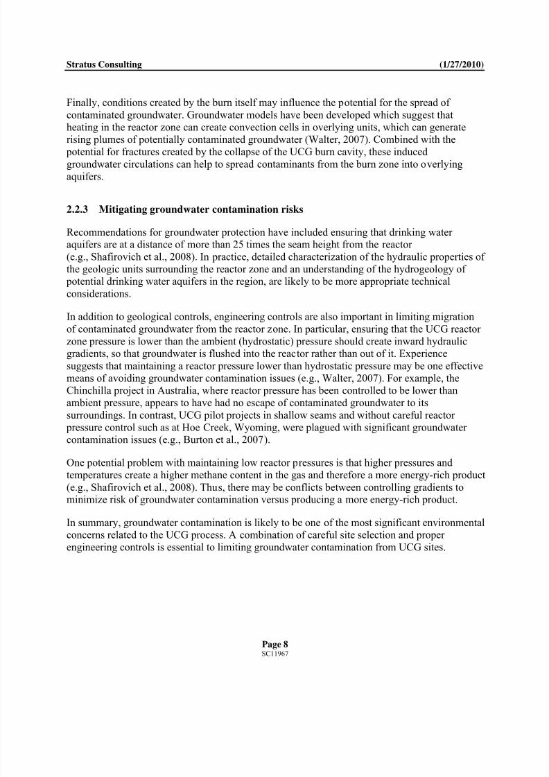
Finally, conditions created by the burn itself may influence the potential for the spread of
contaminated groundwater. Groundwater models have been developed which suggest that
heating in the reactor zone can create convection cells in overlying units, which can generate
rising plumes of potentially contaminated groundwater (Walter, 2007). Combined with the potential for fractures created by the collapse of the UCG burn cavity, these induced
groundwater circulations can help to spread contaminants from the burn zone into overlying
aquifers.
2.2.3 Mitigating groundwater contamination risks
Recommendations for groundwater protection have included ensuring that drinking water aquifers are at a distance of more than 25 times the seam height from the reactor
(e.g., Shafirovich et al., 2008). In practice, detailed characterization of the hydraulic properties of
the geologic units surrounding the reactor zone and an understanding of the hydrogeology of potential drinking water aquifers in the region, are likely to be more appropriate technical
considerations.
In addition to geological controls, engineering controls are also important in limiting migration
of contaminated groundwater from the reactor zone. In particular, ensuring that the UCG reactor
zone pressure is lower than the ambient (hydrostatic) pressure should create inward hydraulicgradients, so that groundwater is flushed into the reactor rather than out of it. Experience
suggests that maintaining a reactor pressure lower than hydrostatic pressure may be one effective
means of avoiding groundwater contamination issues (e.g., Walter, 2007). For example, theChinchilla project in Australia, where reactor pressure has been controlled to be lower than
ambient pressure, appears to have had no escape of contaminated groundwater to its
surroundings. In contrast, UCG pilot projects in shallow seams and without careful reactor
pressure control such as at Hoe Creek, Wyoming, were plagued with significant groundwater contamination issues (e.g., Burton et al., 2007).
One potential problem with maintaining low reactor pressures is that higher pressures and
temperatures create a higher methane content in the gas and therefore a more energy-rich product
(e.g., Shafirovich et al., 2008). Thus, there may be conflicts between controlling gradients tominimize risk of groundwater contamination versus producing a more energy-rich product.
In summary, groundwater contamination is likely to be one of the most significant environmentalconcerns related to the UCG process. A combination of careful site selection and proper
engineering controls is essential to limiting groundwater contamination from UCG sites.
8/3/2019 CIRI Underground Coal Gassification Report
http://slidepdf.com/reader/full/ciri-underground-coal-gassification-report 11/39
Stratus Consulting (1/27/2010)
Page 9SC11967
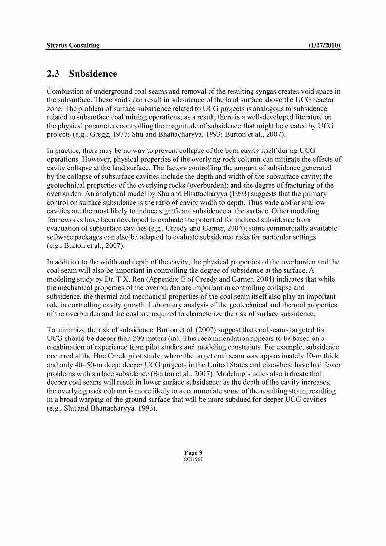
2.3 Subsidence
Combustion of underground coal seams and removal of the resulting syngas creates void space inthe subsurface. These voids can result in subsidence of the land surface above the UCG reactor
zone. The problem of surface subsidence related to UCG projects is analogous to subsidence
related to subsurface coal mining operations; as a result, there is a well-developed literature onthe physical parameters controlling the magnitude of subsidence that might be created by UCG
projects (e.g., Gregg, 1977; Shu and Bhattacharyya, 1993; Burton et al., 2007).
In practice, there may be no way to prevent collapse of the burn cavity itself during UCG
operations. However, physical properties of the overlying rock column can mitigate the effects of cavity collapse at the land surface. The factors controlling the amount of subsidence generated
by the collapse of subsurface cavities include the depth and width of the subsurface cavity; thegeotechnical properties of the overlying rocks (overburden); and the degree of fracturing of the
overburden. An analytical model by Shu and Bhattacharyya (1993) suggests that the primarycontrol on surface subsidence is the ratio of cavity width to depth. Thus wide and/or shallow
cavities are the most likely to induce significant subsidence at the surface. Other modelingframeworks have been developed to evaluate the potential for induced subsidence from
evacuation of subsurface cavities (e.g., Creedy and Garner, 2004); some commercially available
software packages can also be adapted to evaluate subsidence risks for particular settings(e.g., Burton et al., 2007).
In addition to the width and depth of the cavity, the physical properties of the overburden and the
coal seam will also be important in controlling the degree of subsidence at the surface. A
modeling study by Dr. T.X. Ren (Appendix E of Creedy and Garner, 2004) indicates that while
the mechanical properties of the overburden are important in controlling collapse andsubsidence, the thermal and mechanical properties of the coal seam itself also play an important
role in controlling cavity growth. Laboratory analysis of the geotechnical and thermal properties
of the overburden and the coal are required to characterize the risk of surface subsidence.
To minimize the risk of subsidence, Burton et al. (2007) suggest that coal seams targeted for UCG should be deeper than 200 meters (m). This recommendation appears to be based on a
combination of experience from pilot studies and modeling constraints. For example, subsidence
occurred at the Hoe Creek pilot study, where the target coal seam was approximately 10-m thick
and only 4050-m deep; deeper UCG projects in the United States and elsewhere have had fewer
problems with surface subsidence (Burton et al., 2007). Modeling studies also indicate that
deeper coal seams will result in lower surface subsidence: as the depth of the cavity increases,the overlying rock column is more likely to accommodate some of the resulting strain, resulting
in a broad warping of the ground surface that will be more subdued for deeper UCG cavities
(e.g., Shu and Bhattacharyya, 1993).
8/3/2019 CIRI Underground Coal Gassification Report
http://slidepdf.com/reader/full/ciri-underground-coal-gassification-report 12/39
Stratus Consulting (1/27/2010)
Page 10SC11967
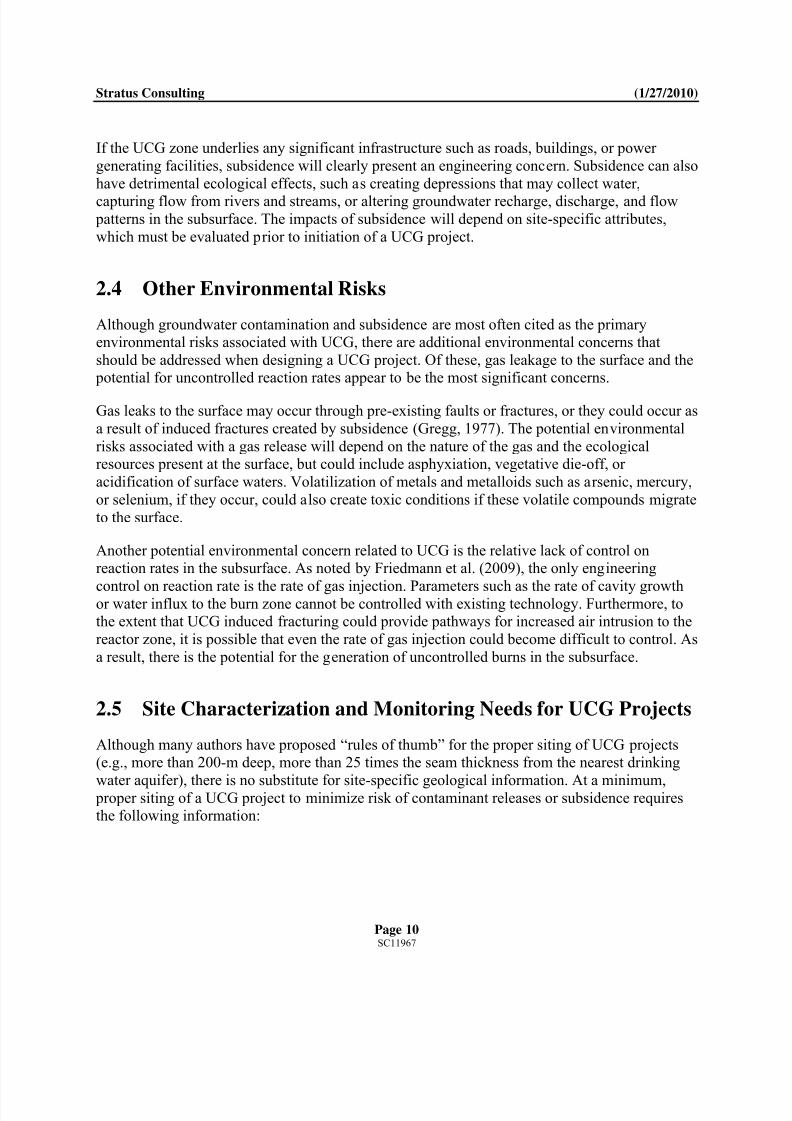
If the UCG zone underlies any significant infrastructure such as roads, buildings, or power
generating facilities, subsidence will clearly present an engineering concern. Subsidence can also
have detrimental ecological effects, such as creating depressions that may collect water,
capturing flow from rivers and streams, or altering groundwater recharge, discharge, and flow patterns in the subsurface. The impacts of subsidence will depend on site-specific attributes,
which must be evaluated prior to initiation of a UCG project.
2.4 Other Environmental Risks
Although groundwater contamination and subsidence are most often cited as the primaryenvironmental risks associated with UCG, there are additional environmental concerns that
should be addressed when designing a UCG project. Of these, gas leakage to the surface and the potential for uncontrolled reaction rates appear to be the most significant concerns.
Gas leaks to the surface may occur through pre-existing faults or fractures, or they could occur as
a result of induced fractures created by subsidence (Gregg, 1977). The potential environmental
risks associated with a gas release will depend on the nature of the gas and the ecologicalresources present at the surface, but could include asphyxiation, vegetative die-off, or
acidification of surface waters. Volatilization of metals and metalloids such as arsenic, mercury,
or selenium, if they occur, could also create toxic conditions if these volatile compounds migrate
to the surface.
Another potential environmental concern related to UCG is the relative lack of control onreaction rates in the subsurface. As noted by Friedmann et al. (2009), the only engineering
control on reaction rate is the rate of gas injection. Parameters such as the rate of cavity growthor water influx to the burn zone cannot be controlled with existing technology. Furthermore, tothe extent that UCG induced fracturing could provide pathways for increased air intrusion to the
reactor zone, it is possible that even the rate of gas injection could become difficult to control. As
a result, there is the potential for the generation of uncontrolled burns in the subsurface.
2.5 Site Characterization and Monitoring Needs for UCG Projects
Although many authors have proposed “rules of thumb” for the proper siting of UCG projects(e.g., more than 200-m deep, more than 25 times the seam thickness from the nearest drinking
water aquifer), there is no substitute for site-specific geological information. At a minimum, proper siting of a UCG project to minimize risk of contaminant releases or subsidence requiresthe following information:

8/3/2019 CIRI Underground Coal Gassification Report
http://slidepdf.com/reader/full/ciri-underground-coal-gassification-report 13/39
Stratus Consulting (1/27/2010)
Page 11SC11967
Characterization of the geologic units above and below the target coal seam, including a
consideration of the lateral continuity, heterogeneity, porosity, permeability, and
continuity of confining layers and overburden
Characterization of the physical nature of the coal seam, including depth, width,
thickness, and permeability, with particular attention paid to the potential size and spatialextent of the burnout area from UCG
Geochemical and mineralogic characterization of the coal seam and host rock to evaluate
potential contaminants of concern, such as sulfides, metals, metalloids, or other trace
impurities
A pilot burn test of samples from the target coal seams that would identify the gases
produced by UCG
Identification and characterization of groundwater aquifers in the subsurface, includingtheir chemistry (e.g., major, minor, and trace), groundwater flow directions, and
horizontal and vertical hydraulic conductivity
Laboratory analysis of the thermal and mechanical properties of the target coal seams and
overlying stratigraphy, to enable an evaluation of the potential risk of subsidence
resulting from UCG burnout
Evaluation of existing and potential faulting in the area, with particular attention paid towhether faults/fractures are sealed or transmissive
Evaluation of existing wells and boreholes, their location, depth, and the integrity of wellconstruction and sealing/plugging materials, and stability under UCG-imposed
conditions.
In order to properly characterize the subsurface stratigraphy, exploratory boreholes and
downhole geophysical measurements should be tied to seismic lines to enable a completecharacterization of the lateral continuity of coal seams and surrounding aquifers and aquitards.
Burton et al. (2007) also stress the importance of understanding the depositional context of coal beds targeted for UCG, because this basic geologic framework can be used to evaluate the lateral
extent of coal seams and their connection to surrounding permeable units. For example, coal
seams deposited in tidal environments may be more laterally continuous than coals deposited
along floodplains, and the overlying stratigraphy may also be more predictable based on basic principles of sequence stratigraphy. Empirical data from seismic lines and boreholes should
therefore be coupled with an understanding of the depositional environment of the target coal
seams, so that their lateral continuity and relationship to overlying materials can be inferred based on geological constraints.

8/3/2019 CIRI Underground Coal Gassification Report
http://slidepdf.com/reader/full/ciri-underground-coal-gassification-report 14/39
Stratus Consulting (1/27/2010)
Page 12SC11967
If site characterization data demonstrate that the environmental risks of the project can be
managed and the project proceeds, the following monitoring requirements should be considered:
The pressure in the burn cavity should be monitored and managed to ensure thathydraulic gradients are directed inward, to minimize groundwater flow out of the cavity
Groundwater in surrounding aquifers should be sampled and monitored regularly, to
detect any contaminant migration from the burn cavity
Tiltmeters, radar interferometry, and/or high-resolution differential global positioning
system (GPS) should be used to monitor for subsidence at the surface
Gas detection monitoring should be implemented to detect any surface leakage of syngasthat may occur.
3. Environmental Risks of CCS
Conceptually, UCG may be well-suited to CCS, since (1) coal seams are commonly located inthe types of sedimentary environments where formations suitable for CCS are found; and
(2) CO2 can be relatively easily and economically separated from the pre-combustion gas stream,
compared to post-combustion separation (Friedmann et al., 2009). The combination of UCG andCCS technology may therefore become common. Like UCG, however, CCS also has a number
of technological challenges and environmental risks that need to be carefully addressed.
The primary risks of CCS relate to unanticipated or uncontrolled releases of CO2 from thesequestration zone. The environmental risks associated with such releases range from
acidification of groundwater aquifers to asphyxiation of biota, including humans, at the landsurface. In addition, since CCS is designed to mitigate climate change risk, loss of CO2 from the
sequestration zone also negates the intended environmental benefits of the process.
3.1 Geologic Sequestration Systems
According to U.S. EPA (2008), geologic sequestration (GS) systems for CCS consist of an
injection zone and an overlying confining system. The injection zone is a geologic formation or
group of formations that are targeted for CO2 injection. Formations with relatively high porosityand high permeability, such as sandstones, allow for greater storage of CO2 and are preferred
injection zone materials. To maximize storage capacity, the CO2 is compressed and injected as asupercritical fluid. These artificially high pressures create a tendency for the injected CO2 to
diffuse out of the injection zone. In addition, the injected CO2 will have a tendency to rise due to

8/3/2019 CIRI Underground Coal Gassification Report
http://slidepdf.com/reader/full/ciri-underground-coal-gassification-report 15/39
Stratus Consulting (1/27/2010)
Page 13SC11967
the relative buoyancy of supercritical CO2 compared to the native fluids (e.g., brine or saline
water) present within the injection zone. The role of the confining system, also sometimes
referred to as a caprock, is to prevent the upward migration of the injected CO2. Thus, low-
permeability geologic formations such as siltstones or mudstones that are thick and laterallycontinuous are preferred formations for confining systems (IPCC, 2005; U.S. EPA, 2008).
In this section, we describe the mechanisms at play to keep CO2 sequestered in the subsurface,
the types of geologic settings being considered for CCS, a brief summary of current CCSoperations, regulatory considerations, and potential risks and adverse impacts associated withCCS.
3.1.1 GS CO2 trapping mechanisms
The CO2 is retained in the injection zone through a combination of different trappingmechanisms. The confining system, a physical stratigraphic trap that inhibits the upward
migration of CO2, provides one of the most important trapping mechanisms.
Within the injection zone, additional trapping mechanisms can occur to sequester the CO2. These
include residual CO2 trapping, dissolution trapping, preferential adsorption trapping, and mineral
trapping. Residual CO2 trapping occurs when the CO2 is retained by capillary forces in some of the pores of the injection zone geologic formation(s). Solubility trapping can occur as a result of
the dissolution of CO2 into the fluid inhabiting the pore space of the geologic formations(e.g., saline water). The fluids become denser as a result of CO2 dissolution, and will tend to
sink, thus further entraining the CO2 in the subsurface. CO2 trapping through preferential
adsorption occurs when CO2 adsorbs to certain geologic materials such as coal and shale thathave a high affinity for CO2. Mineral trapping occurs when the CO2 reacts with the injection
zone rock and/or fluids to form solid minerals. Although mineralization is the most permanenttrapping mechanism in GS systems, it occurs relatively slowly compared to the other
mechanisms [see IPCC (2005) and U.S. EPA (2008) and references therein for more detailed
descriptions of these trapping mechanisms].
3.1.2 Geologic settings under consideration for GS
There are a number of different types of geologic settings under consideration for sequestration.
These include deep saline formations (DSFs), oil and gas reservoirs (both depleted formations,
and formations targeted for enhanced oil and gas recovery), and coal seams.
DSFs are sedimentary geologic units in which the pore space between the formation rock is filled
with saline (salty) water. These formations are found in subsurface sedimentary basins and are
deep enough (800–1,000 m) to achieve pressures that will keep the CO2 in its compressed,

8/3/2019 CIRI Underground Coal Gassification Report
http://slidepdf.com/reader/full/ciri-underground-coal-gassification-report 16/39
Stratus Consulting (1/27/2010)
Page 14SC11967
supercritical phase. There are many very large sedimentary basins across the United States, and
DSFs are believed to have the greatest capacity for sequestration, compared to the other settings
under consideration (Dooley et al., 2006; NETL, 2007). The National Energy Technology
Laboratory (NETL) has estimated that DSFs may have the capacity to store between 1,000 and3,700 billion tons of CO2 (NETL, 2007). However, they are typically less well characterized thanother settings, such as oil and gas fields, and thus storage capacities are somewhat uncertain, and
may be overly optimistic.
Oil and gas fields have stored oil and natural gas for hundreds of thousands to millions of years prior to resource extraction, and are thus believed to be good potential candidates to store CO2
for long periods of time (Benson et al., 2002; IPCC, 2005). CO2 is currently injected into some
reservoirs to enhance the extraction of oil, in a process called EOR. Similarly, CO2 is also used
in some reservoirs to enhance the extraction of natural gas. Both depleted oil and gas fields, andEOR sites, could potentially be transitioned to GS. These reservoirs are typically very well
characterized, which is advantageous for their use to store CO2. However, as a result of extraction activities, these formations are typically penetrated by many wells and boreholes,
which is disadvantageous to GS, because the penetrations could be conduits for CO2 leakage
(Celia et al., 2004; Heller, 2005). According to NETL, the estimated CO2 storage capacityassociated with EOR sites is 90 billion tons (NETL, 2007). This is much smaller than the
estimated capacity of DSFs. However, these settings may be attractive candidates for immediateimplementation of CCS, because much of the needed infrastructure and CO2 injection
technology is already in place.
Coal seams have also been suggested for GS. Because of coal’s high affinity for CO2, CO2 may
be stored in coal beds through adsorption to the coal surface. CO2 may also enhance the
extraction of methane from coal beds (enhanced coalbed methane), because coal’s high affinityfor CO2 may displace methane present in the coal beds, which could then be captured for extraction. However, the small-scale fractures (cleats) that allow fluid flow through coal seams
can become plugged as a result of CO2 adsorption, and thus restrict further CO2 storage
(Haszeldine, 2006). Thus, the sequestration of CO2 in coal beds may be challenging.
Other geologic settings, such as volcanically deposited basalts, oil or gas-rich shale, geologic
repositories such as salt caverns, and abandoned mines may also be considered for GS, but are
not currently major focuses (see IPCC, 2005, for further discussion of these other settings).
3.1.3 Natural and industrial analogs and existing CCS operations
Natural and industrial systems that have stored CO2 and other fluids (e.g., gases such as naturalgas) may provide analogs for GS, demonstrating the potential ability to store CO2 and other fluids in the subsurface. CO2 accumulates underground naturally in a variety of geologic settings,

8/3/2019 CIRI Underground Coal Gassification Report
http://slidepdf.com/reader/full/ciri-underground-coal-gassification-report 17/39
Stratus Consulting (1/27/2010)
Page 15SC11967
and there are numerous natural analogs that demonstrate the long-term trapping of CO2 in the
subsurface. For example, 200 million metric tons of naturally occurring CO2 have remained
trapped in the Pisgah Anticline in central Mississippi, northeast of the Jackson Dome, for more
than 65 million years with no evidence of leakage (IPCC, 2005). Industrial analogs include the practice of injecting and temporarily storing natural gas in underground reservoirs. The oil andgas industry has engaged in this practice for nearly 100 years (IPCC, 2005). Experience from
these natural gas storage operations is mixed. While these operations demonstrate that fluids and
gases can be stored in the subsurface, there have been several instances of documented leakageof natural gas to the surface, either due to induced fracturing caused by application of excessive
pressures to the formations, pre-existing leakage pathways through the confining system, or leakage at improperly sealed or plugged wells (Perry, 2005). Furthermore, these sites are
generally used for temporary storage and hence do not provide insight into the long-term
feasibility of underground storage of fluids and gases. These sites do provide some evidence thatwith careful management, confining systems can be exposed to repeated stress cycling
(i.e., depressurizing and pressurizing) without adverse effects on seal integrity, which maysupport the use of depleted oil and gas reservoirs for CO2 storage.
As mentioned above, the oil and gas industry also has experience in the injection of CO2 throughenhanced product recovery projects. EOR has been practiced for over 35 years, and these
projects contribute substantial knowledge about the design of CO2 injection wells andtechnologies for handling, injecting, and monitoring injected supercritical CO2 (Benson et al.,
2002; Heinrich et al., 2003; IPIECA, 2007). However, such projects are designed to maximize
oil production, and thus provide rather limited insight into the long-term storage of CO2 in thesubsurface.
While few in number, currently operating pilot and commercial CCS projects have thus far demonstrated that CCS can be successfully implemented. Currently operating commercial projects include the Sleipner project in the North Sea (Norway), the Weyburn EOR project
(Canada), and the In Salah Gas Formation project (Algeria). Additional commercial GS projects
that are in the planning stages and are anticipated to be underway in the near future include theGorgon Joint Venture (Barrow Island, Australia) and other potential sites in Europe and the
United States. There are also a number of smaller-scale research field experiments that haverecently been conducted or are underway at sites in the United States and internationally.
Examples include the CO2 SINK Ketzin site in Germany, the U.S. Frio Brine Experiment
(Texas), and the currently underway regional projects supported by the U.S. Department of Energy’s (DOE’s) Regional Carbon Sequestration Partnerships Program [see U.S. DOE (2010)
for a summary of this program]. For a more comprehensive list of current and planned GS projects in the United States and around the world, see NETL’s CO2 Storage website
(http://www.netl.doe.gov/technologies/carbon_seq/core_rd/world_projects.html) and the Scottish
Centre for Carbon Storage website (http://www.geos.ed.ac.uk/ccsmap).

8/3/2019 CIRI Underground Coal Gassification Report
http://slidepdf.com/reader/full/ciri-underground-coal-gassification-report 18/39
Stratus Consulting (1/27/2010)
Page 16SC11967
Operating commercial and experimental projects have demonstrated thus far that CO2 can be
injected and sequestered in geologic formations. However, these sites have been operating for
only a relatively short period of time (Sleipner is the longest running operation, and began in
1996), and hence do not yet demonstrate the long-term storage of CO2 in the subsurface over required storage time periods of hundreds to thousands of years. Full commercial-scaledeployment of GS will also involve injecting much larger volumes of CO2 than currently
operating projects. Because of their smaller scale, current projects likely do not demonstrate the
full range of scenarios that may be encountered in commercial-scale deployment. For example,commercial-scale GS projects will encompass areas that may be miles in diameter (as opposed to
for example the small fraction of a mile encompassed by most DOE pilot projects), and thus may be more likely to:
Encounter geologic heterogeneities that may serve as CO2 leakage pathways, includingfaults and fractures, or potential anthropogenic pathways such as unplugged wells and
boreholes
Face challenges regulating pressure, and thus experience adverse pressure effects that cancause fracturing or other adverse impacts, such as the displacement of brine into
overlying aquifers, or regional effects on groundwater flow
Encounter basin-wide effects, and influences of neighboring projects.
However, pilot projects can nevertheless provide useful information, particularly if multiple
projects are implemented and evaluated across a variety of geologic settings.
3.1.4 Regulatory framework for CCS
Federal and State regulations address the injection of fluids into the subsurface for the protection
of underground sources of drinking water (USDWs), under the Safe Drinking Water Act(SDWA). Specifically, the U.S. Environmental Protection Agency (U.S. EPA) Underground
Injection Control (UIC) program regulates the injection of fluids into the subsurface (including
liquids, gases, and semisolids), and the regulations are designed to ensure that injected fluids donot endanger USDWs.
According to the U.S. EPA (2010), GS of CO2 through well injection meets the definition of “underground injection” in Section 1421(d)(1) of the SDWA, and the U.S. EPA has authority for underground injection under the SDWA UIC program. The U.S. EPA, states, territories, and
tribes that have primacy for UIC programs (“Primacy States”) act as co-regulators to protectUSDWs from any potential endangerment from underground injection of CO2.

8/3/2019 CIRI Underground Coal Gassification Report
http://slidepdf.com/reader/full/ciri-underground-coal-gassification-report 19/39
Stratus Consulting (1/27/2010)
Page 17SC11967
In July 2008, the U.S. EPA published a Proposed Rule for Federal Requirements for CO2 GS
wells under the UIC program. The Proposed Rule describes a new class of wells for the
regulation of CO2 injection, and addresses issues related to siting, well construction, monitoring,
and site closure. See U.S. EPA’s website(http://www.epa.gov/safewater/uic/wells_sequestration.html) for the history and current status of the Proposed Rule.
3.2 Potential Risks and Adverse Impacts Associated with CCS
The main environmental risks associated with CCS are related to the potential for leakage from
the GS formation, and the potential for adverse impacts in the subsurface associated with theapplied injection pressures. Key attributes of GS systems that have been identified as particularly
important when evaluating the potential risk of leakage of CO2 from the injection zone include
wells, faults, and fracture zones. The applied injection pressures may also induce fracturing or reactivate faults, and may have other adverse impacts to the subsurface, such as displacing large
volumes of brine, or potentially causing changes in groundwater flow directions.
Wells (and other artificial penetrations such as boreholes) have been identified as one of the most probable conduits for the escape of CO2 from GS systems (Gasda et al., 2004; Benson, 2005;
IPCC, 2005; Carey et al., 2007). If not properly sealed and plugged, wells and boreholes that
were previously installed during exploration and resource extraction can be a direct conduit for CO2 to escape from depth to the surface. Such wells may also act as pathways for brines to
contaminate overlying freshwater aquifers. Even properly completed wells may pose a risk of leakage, as the acid generated when CO2 contacts water may degrade well construction materials
over time (Scherer et al., 2005). Identifying and evaluating abandoned wells may be particularlychallenging in some geologic settings, such as depleted oil and gas fields. Furthermore, the GSinjection and monitoring wells themselves need to be properly constructed and operated in order
to avoid leakage of CO2, and other fluids such as brine. Experience from other analogousinjection projects (such as those used in oil and gas operations) has shown that leakage from the
injection well itself, as a result of improper completion or deterioration of the casings, packing,
or cement well materials, is one of the most significant well failure modes (Benson et al., 2002;IPCC, 2005).
The potential for existing faults and fractures to act as fluid pathways in GS systems is a functionof numerous factors, comparable to those described above for UCG. These include the level of
applied pressure, whether they are sealed or transmissive; their stratigraphic position with respectto the confining system, their orientation, and their geometry with respect to the applied pressures. Tectonically active settings, such as the proposed CIRI site and southern Alaska in
general, may be more likely to have transmissive faults and/or fracture zones, and may beunsuitable for GS. Faults and fractures may also be induced if the GS system is overpressurized

8/3/2019 CIRI Underground Coal Gassification Report
http://slidepdf.com/reader/full/ciri-underground-coal-gassification-report 20/39
Stratus Consulting (1/27/2010)
Page 18SC11967
during injection of CO2. The risk of injection pressure exceeding fracture pressure can be
reduced through understanding the relevant geologic attributes, careful site characterization,
careful operation of GS systems, and monitoring (IPCC, 2005). The potential for existing and
induced fractures and faults to result in adverse impacts will depend on numerous additionalfactors, including whether the faults are connected to an overlying receptor, whether they may be
connected to other fluid-conducting pathways (such as wells), and whether or not they may beresealed by geochemical processes associated with GS (U.S. EPA, 2008).
Additional factors that will influence the risk of CO2 leakage include the lateral extent, thickness,
and permeability of the confining system. Furthermore, the physical capacity, injectivity and
geochemical and geomechanical properties of the injection zone may also influence thelikelihood of leakage.
There are numerous potential adverse impacts resulting from the leakage of CO2 (as well as other
fluids, such as brine) and changes in subsurface pressure caused by CO2 injection. According toU.S. EPA (2008), categories of receptors that could potentially be adversely impacted by CCS
include human health and welfare, the atmosphere, ecosystems, groundwater and surface water,
and the geosphere. The vulnerability of a GS system to these adverse impacts is a function of both the presence of the key receptors in the impact categories, and the levels of exposure. A
number of factors affect exposure, including but not limited to the concentration and volume of the release, the rate of release (i.e., slow vs. sudden), the proximity of the release to the receptor,
and wind or wave dispersion. Impacts are also affected by whether the release is acute but
limited (in time or spatial extent) or chronic. The potential impact categories are brieflysummarized below; for a more detailed discussion, see U.S. EPA (2008):
Human health and welfare: Adverse health effects caused by CO2 can range from minor,reversible effects to mortality, depending on the concentration of CO2 and the length of
the exposure (Benson et al., 2002; CEC, 2007). Release of CO2 may also adverselyimpact recreational and economic resources by restricting access or use or by changing
the quantity and quality of the resource. Resources that could potentially be impacted byCO2 leakage include mineral extraction, forestry, fisheries, or other harvested natural
resources, which could in turn result in adverse economic impacts to humans
Atmospheric impacts: In some cases, small releases of CO2 from GS may not adversely
impact local environmental receptors (e.g., ecological receptors, groundwater and surfacewater, humans). However, such releases do reduce the climate benefits of capturing CO2,
thus decreasing the overall effectiveness of GS as a climate change mitigation strategy.
Ecosystem impacts: Leakage of CO2 could have adverse impacts on soil-dwelling animals
and microbes (Sustr and Siemk, 1996; Benson et al., 2002), plants (MeGee and Gerlach,1998; Saripalli et al., 2002), surface-dwelling animals (Benson et al., 2002), and aquatic

8/3/2019 CIRI Underground Coal Gassification Report
http://slidepdf.com/reader/full/ciri-underground-coal-gassification-report 21/39
Stratus Consulting (1/27/2010)
Page 19SC11967
organisms, particularly calcifying organisms (Turley et al., 2004; Miles et al., 2007;
Spicer et al., 2007). Particular attention may be required to address protected or
endangered species if present.
Groundwater and surface water quality and quantity: Leakage of CO2 into aquifers can
have detrimental impacts on water quality. For example, the dissolution of CO2 in the
water can create acidity which can in turn dissolve metal-bearing minerals, or result in
the desorption of metal and organic contaminants adsorbed to geologic formations (Jaffeand Wang, 2003; Wang and Jaffe, 2004). The pressure-induced displacement of brine or salty waters into overlying aquifers can also negatively impact water quality, and can
potentially result in the loss of USDWs. Pressure changes associated with injection of
CO2 may also cause changes in flow directions in groundwater and surface water bodies
and points of recharge and discharge (Nicot et al., 2006; Tsang et al., 2007). This may inturn negatively impact municipal water supplies, and the water balance of local
ecosystems. The spatial area affected by pressure changes associated with injection willtypically be significantly larger than the injected CO2 plume itself, and thus, adverse
impacts associated with pressure changes could potentially be experienced over very
large spatial areas.
Geosphere: Changes in subsurface pressure from GS can have direct impacts on the locallandmass itself. Subsurface pressure changes that exceed the subsurface geologic
formation’s geomechanical strength could cause fracturing or reopening of faults andfracture zones (Quintessa, 2004; IPCC, 2005). Impacts could also include induced
seismic activity, including earthquakes in the extreme case (Healey et al., 1968) and land
deformation through uplift (Quintessa, 2004; Birkholzer et al., 2007).
In general, the overall likelihood of adverse impacts is expected to decline over time at GS sites.
This assumption is based on a number of factors, including the greater permanence of secondary
trapping mechanisms, such as dissolution, which decreases buoyancy, and mineralization; the
anticipated return to pre-injection pressure conditions once injection stops in most cases; andimproved characterization and modeling of the GS system over time (U.S. EPA, 2008).
3.3 Site Characterization and Monitoring Needs for CCS Systems
While experience from existing projects and natural and industrial analogs to GS demonstrates
that CO2 can be safely sequestered in geologic formations, there is the potential for unanticipatedmigration and leakage of injected CO2 and other fluids such as brine, as well as the potential for
adverse impacts caused by excessive pressure. As a result, site characterization and monitoringto evaluate potential risks are necessary components of GS projects. Specific purposes for site
characterization, monitoring, and applicable technologies at CCS sites include:
8/3/2019 CIRI Underground Coal Gassification Report
http://slidepdf.com/reader/full/ciri-underground-coal-gassification-report 22/39
Stratus Consulting (1/27/2010)
Page 20SC11967
Establishing baseline conditions. CO2 is ubiquitous in the environment, and
concentrations vary diurnally, seasonally, and annually, and spatially. Determining
background levels of CO2 and understanding natural fluctuations is necessary to discern
whether detected CO2 is attributable to leakage from the GS site, or to other sources. Inaddition, many technologies, such as seismic profiling, identify CO2 on a comparative
basis, and thus measurements need to be taken prior to injection. The techniques selected
to establish a baseline will be dependent upon site-specific conditions, and anticipatedmonitoring needs during injection. Examples of technologies that may be applied include
seismic imaging; wellhead and formation pressure monitoring techniques; temperature
and fluid composition measurement techniques; electrical measurements of subsurfaceconductivity/resistance; atmospheric and soil gas monitoring technologies; and land
surface deformation monitoring technologies (Benson et al., 2004; WRI, 2008; Bacon
et al., 2009; Johnson, 2009).
Identifying and providing oversight of targeted locations and site features. Specificlocations and site features should be identified and targeted for monitoring if they areknown or suspected to have elevated risk of CO2 leakage and adverse impacts. For
example, existing wells and faults should be targeted for characterization and monitoring
because of their elevated potential to act as CO2 conduits, which can result in leakage.During site characterization, monitoring techniques can be tested and selected to target
site-specific attributes (Benson et al., 2004). During injection and site closure, monitoring
can help identify existing or newly developed risks and inform the application of additional, targeted monitoring techniques if needed. The specific type of monitoring
technique to be used will depend upon the specific site characteristic that is being
assessed, and could include seismic surveys, tracers, borehole logs, pressure
measurements at the wellhead and in the formation, formation fluid sampling, surfacewater sampling, and air and soil gas sampling.
Ensuring injection controls. Monitoring the condition of the injection well, the injection
rate, and wellhead and formation pressure are important to verify the amount of CO 2 injected and to avoid leakage. Available technologies to monitor that injection controls
are handled appropriately include wellhead and formation pressure gauges, core logging,
and wellbore annulus pressure measurements (Benson et al., 2004; IPCC, 2005; Benson,2007; Freifeld et al., 2009; NETL, 2009).
Confirming the quantity and location of injected CO2, and detecting unanticipated
leakage: The movement and fate of injected CO2 are influenced by injection-relatedfactors, properties of the CO2, and properties of the GS formations. As a result, many
different subsurface parameters may need to be measured to assess the location andquantity of the injected CO2. Existing pressure gradients and gradients induced by
injection can influence CO2 movement, and so techniques that measure the injection rate

8/3/2019 CIRI Underground Coal Gassification Report
http://slidepdf.com/reader/full/ciri-underground-coal-gassification-report 23/39
Stratus Consulting (1/27/2010)
Page 21SC11967
and formation pressure gradients can help monitor CO2 in the subsurface. Other examples
of techniques that may be used to confirm the location and quantity of injected CO 2
include seismic surveys; electrical and electromagnetic methods, such as electrical
resistance tomography; gamma ray, resistivity and other types of logging; and fluid andmineral sampling methods (Benson et al., 2004; Benson, 2007; Bachu and Bennion,
2009; Bachu et al., 2009; NETL, 2009). Several monitoring techniques may be used to
detect surface leakage, including sampling air using eddy covariance, infrared and other techniques; sampling soil gas with soil gas probes; using tracers (small quantities of a
chemical compound or isotope added to trace flow patterns); monitoring for land surface
deformation; measuring productivity of local flora and fauna; and sampling overlyinghydrologic systems (Chabora and Benson, 2009; Darby et al., 2009; Jones et al., 2009;
Schwarz et al., 2009).
Assessing environmental and human health impacts of leakage if they occur . If CO2 leaks
from the targeted injection zone, adverse impacts to the environment and human healthcan occur. Monitoring techniques can help assess the severity of adverse impacts by providing information on the amount of leaked CO2. Site-specific receptors may also be
targeted for monitoring, such as sensitive or endangered species, or USDWs, to ensure
that they are not adversely impacted by unanticipated CO2 migration and leakage.
Detecting induced microseismicity. Microseismic activity may be induced by CO2 injection if pressures within the target zone are high enough to cause a release of
accumulated strain on fault zones. Monitoring can help recognize induced
microseismicity, so that mitigative actions, such as reducing the injection pressure, can be
implemented.
Resolving liability/legal disputes. Monitoring could potentially be used to help resolvedisputes arising from unanticipated leakage of CO2. For example, liability disputes could
arise if other underground natural resources, such as minerals or oil and gasreserves, were adversely impacted by injected CO2 that has migrated outside the target
formation. Damages could be sought by parties that have an interest in the impacted
resources from the legally responsible injector of the CO2. Monitoring can assist withdetermining which injector is liable in the event that multiple injectors are in proximity to
the damaged resources. Liability disputes could be complicated by the additional factor
that projects can be in injection and post-injection site care phases at varying times; if leakage occurs while one project is operational and a nearby project is in post-injection
site care phase, the leaking CO2 could be emanating from either the closed or thecurrently operational project (Wilson et al., 2007; GAO, 2008; CCSReg, 2009). There
may also be questions about the long-term liability and legal responsibility of leakagefrom sites after closure of operations.

8/3/2019 CIRI Underground Coal Gassification Report
http://slidepdf.com/reader/full/ciri-underground-coal-gassification-report 24/39
Stratus Consulting (1/27/2010)
Page 22SC11967
4. CIRI Proposal and Study Site
4.1 Information on CIRI Proposal
Although the details of CIRI’s proposed project are limited, we have obtained general
information about their plans from the website that they have set up for this project
(http://www.cirienergy.com/) and from the coastal management and exploration permitapplications they submitted in late 2009 (Belowich, 2009). This section contains a brief
description of their plans based on this information, recognizing that the details of their plans are
not likely to emerge until after their exploratory drilling has been completed.
CIRI’s presentation of their proposed project indicates that the target coal seams for UCG will be
more than 650 feet (ft) deep and will be isolated from freshwater aquifers by “strong and
impermeable overlying rock layers” (CIRI, 2009). Beyond these generalities, however, therehave been no details provided about the thickness of the coal seams targeted; the stratigraphy of
the overlying geologic units; or the quality and character of the coal beds themselves.
CIRI also indicates that they will be capturing CO2 from their syngas stream using existing
technologies. Again, however, no details have been given as to the mechanisms of capturing or
sequestering the CO2. The CIRI proposal indicated that CO2 would be sequestered via EOR.However, for EOR to occur, CIRI would need to partner with Cook Inlet oil producers to supply
their carbon stream to existing oil infrastructure. At least one of the Cook Inlet producers,
Chevron, has apparently already indicated that they are not interested in this project(AlaskaCoal.org, 2009), and CIRI has since indicated that EOR may not be a viable alternative.
In such case, CCS could possibly be accomplished by GS into DSFs or other geologic settings,
or by re-injecting CO2 into the burn cavities left behind by UCG. Either of these alternatives
would require significant additional investigation into the geology of the targeted sequestrationzones.
CIRI’s exploration permit indicates that they plan to drill two deep boreholes to 2,500 ft, three
boreholes to 2,000 ft, and one to 1,250 ft (Belowich, 2009). The stated goal of these boreholes is
to enable stratigraphic correlation across major faults and with stratigraphic information from anexisting borehole on the site. Results from deep borehole exploration could also enable
identification of potential CCS targets.

8/3/2019 CIRI Underground Coal Gassification Report
http://slidepdf.com/reader/full/ciri-underground-coal-gassification-report 25/39
Stratus Consulting (1/27/2010)
Page 23SC11967
4.2 Site Geology
Although information about the specific coal beds that CIRI is targeting for UCG remainslimited, this section describes the general geologic setting of the proposed project, with particular
attention paid to the tectonics, stratigraphy, and characteristics of coal seams that will be relevant
to evaluating environmental risks of the project.
4.2.1 Coal bearing units
The Susitna lowlands region is well known for its coal resources. Barnes (1966) estimated the
coal reserves in the region at 2.4 billion tons based on field mapping and aerial reconnaissance
surveys. Subsequent studies have improved understanding of the depositional environment,thickness, and distribution of coal beds throughout the region (e.g., Merritt, 1990; Flores et al.,
1997), as well as the role of faults in exposing different packages of coal-bearing units at thesurface.
As suggested by Burton et al. (2007), a general understanding of the depositional environments
of the coal beds targeted for UCG is one means of assessing their lateral continuity, their general
geochemistry, and their connection to surrounding aquifers. A brief description of available
geologic information is included here.
There are two major coal-bearing units present in the study area: the Beluga Formation, and the
underlying Tyonek Formation. Both of these Miocene (523 million year) units belong to the
Tertiary-aged Kenai Group, which includes interbedded clays, silts, sands, and conglomerates of
a generally nonmarine origin (Barnes, 1966). Merritt (1990) describes the Tyonek Formation asthe result of channel and floodplain sedimentation, and the Beluga Formation as a set of
coalescing alluvial fans. More recent stratigraphic work by Flores et al. (1997) indicates thatsome of the beds within the Tyonek Formation may also have been tidally influenced, suggesting
a fluvial-estuarine depositional environment. Flores et al. (1997) also suggest that much of the
Tyonek Formation was laid down while the Castle Mountain Fault (CMF) was active; thus the
courses of the rivers in which the coal beds were formed are likely to have been controlled bymotion on this fault.
The coal beds in the Tyonek Formation are typically thicker than those in the Beluga Formation:
Some of the Tyonek Formation coals are as much as 5070 ft thick, while the Beluga Formation
coals are typically less than 8 ft (Belowich, 2009). Given the complex geological and structuralsetting of the proposed exploration area, boring logs and more detailed development plans from
CIRI will be necessary before the relationships between coal beds, permeable units, and faults
can be evaluated.

8/3/2019 CIRI Underground Coal Gassification Report
http://slidepdf.com/reader/full/ciri-underground-coal-gassification-report 26/39
Stratus Consulting (1/27/2010)
Page 24SC11967
4.2.2 Structural geology and tectonics
The Beluga and Tyonek formations are typically flat to shallowly dipping (< 15 degrees), except
where locally influenced by motion along the CMF and Moquawkie (Bruin Bay) fault zone.Where these faults are present, the stratigraphic package is tilted or gently folded so that dips can
be up to 3550 degrees (Barnes, 1966). In the southwestern corner of the CIRI exploration block,
the Tyonek and Beluga formations are warped by an east-northeast trending syncline, which
plunges shallowly to the east (Belowich, 2009).2 It is not clear from CIRI’s plans whether thecoal beds involved in this structure may be the target of their exploration further to the northeast.
The CIRI exploration block is crossed by the CMF along its northern edge, and is nearly bisected
by the northeast-trending Moquawkie/Bruin Bay Fault (Figure 4). Both of these faults are high-
angle, and both have accommodated significant displacement. The CMF offsets the Tyonek Formation by as much as 4,000 ft, with the northern block upthrown relative to the southern
block. The Moquawkie/Bruin Bay Fault offsets the stratigraphy by an additional 2,000 ft, withthe western block displaced upwards relative to the eastern block. Although the stratigraphy is
generally shallowly dipping throughout the study area, motion along these faults is likely to havecaused local warping and fracturing near these faults. The influence of these major faults and
associated fractures on fluid migration warrants further investigation.
The entire Cook Inlet region is very active seismically (Figure 5). Recent work on portions of the
CMF indicates that it is active, with the most recent dated surface rupture occurringapproximately 670 years ago, and an average recurrence interval of approximately 700 years
(e.g., Willis et al., 2007). Moderate earthquakes of magnitude 5.7 and 4.5 occurred along the
eastern portions of the CMF in 1984 and 1996, respectively (e.g., Haeussler et al., 2002). The
Moquawkie/Bruin Bay Fault has received relatively less attention in the literature; however,aligned and offset river drainages along its course in the vicinity of the exploration block are
consistent with recent motion along this fault as well. These faults and fractures are potential
pathways for fluid migration to the surface. The influence of seismicity on fracture generationand fluid migration at the proposed site also warrants further investigation once more detailed
site plans have been released.
2. A syncline is a “U” shaped warping of geologic layers. The plunge is the direction and angle that the axis of
this “U” is tilted. The 30-ft thick Beluga coal bed crops out in a “U” shape along the Beluga River canyon, and
the attitude of these beds indicates that the axis of this “U” becomes deeper to the east.

8/3/2019 CIRI Underground Coal Gassification Report
http://slidepdf.com/reader/full/ciri-underground-coal-gassification-report 27/39

8/3/2019 CIRI Underground Coal Gassification Report
http://slidepdf.com/reader/full/ciri-underground-coal-gassification-report 28/39
Stratus Consulting (1/27/2010)
Page 26SC11967
gathered during initial site characterization and monitoring likely used as initial inputs for a
flexible set of models (Bacon et al., 2009). Monitoring data gathered during the initial UCG burnout phase and the early CO2 injection phase can then be used to refine models, if needed. If
unanticipated conditions are detected, the location and frequency of monitoring, and employed
technologies can then be altered so that monitoring occurs where the produced or injected fluids
have come to be located.
Overall, the frequency of measurements may be greatest during the early part of the project,when the least is known about the site, and data are needed for model and instrument calibration.
Longer time intervals between measurements may be sufficient during later phases of syngas
generation and CO2 injection. The initial start-up of both phases of the project is likely to be themost intensive period for modeling activities, including model calibration and refinement, and
Figure 5. Cook inlet seismicity. The location of the CIRI site is approximately at theintersection of the two faults located west of Anchorage.
Source: AEIC, 2006.

8/3/2019 CIRI Underground Coal Gassification Report
http://slidepdf.com/reader/full/ciri-underground-coal-gassification-report 29/39
Stratus Consulting (1/27/2010)
Page 27SC11967
for verification as initial field data are collected. The intensity of modeling activities may also
slow with time, once models are refined and are able to adequately predict subsurface fluid
movement, location, and quantity.
The need for careful site characterization and monitoring is illustrated by experience at well-
characterized GS sites such as Sleipner (North Sea), Frio (Texas), and Weyburn (Saskatchewan).At these sites, model simulations based on initially gathered site characterization data did not
accurately predict the migration and location of the injected CO2. For example, at Sleipner, the
lateral dimensions of the CO2 plume were much smaller than predicted by pre-injection modelsimulations. Compared to predictions, the plume spread out less laterally and more vertically.
Unrecognized discontinuous silt layers within the injection zone were responsible for the
unanticipated distribution of CO2 (Johnson and Nitao, 2003). Unpredicted CO2 migration wasalso observed at Frio, where the CO2 migrated much more quickly than anticipated (Doughty
et al., 2001; Hovorka et al., 2005; Kharaka et al., 2009). At Weyburn, modeled predictions of the
location and shape of the CO2 plume were partially incorrect. A series of faults at the site thatwere not included in the model simulations were believed to be responsible for the unanticipatedresults (Friedmann, 2003). At each of these sites, none of the unanticipated migration resulted in
leakage, and the CO2 remained sequestered in the intended injection zone, thus demonstrating
the potential for successful storage of CO2 in the subsurface. All of these examples, however,reinforce the need for careful, iterative site characterization; flexibility and responsiveness in
monitoring activities; and the need for dynamic monitoring plans so that the location, frequency,
and types of field measurements can be adjusted as needs and conditions change.
6. Conclusions and Recommendations
The project proposed by CIRI has a number of potential environmental benefits when compared
to conventional coal mining. As described above, however, there remain a number of environmental risks associated with both UCG and CCS. Some of the most important of these
risks are:
The risk of groundwater contamination as a result of UCG and/or CCS
The risk of subsidence resulting from cavity formation in the UCG burn-out zone
The risk of syngas and/or CO2 releases to the surface, and associated impacts on surface
water resources, ecosystems, or human health
The risk of induced microseismicity as a result of overpressurizing CCS target zones.

8/3/2019 CIRI Underground Coal Gassification Report
http://slidepdf.com/reader/full/ciri-underground-coal-gassification-report 30/39
Stratus Consulting (1/27/2010)
Page 28SC11967
As it currently stands, the CIRI proposal is far too general to enable a reasoned evaluation of the
environmental risks of the project. Sections 2.5 and 3.3 describe the minimum environmental
characterization data that are required for such a reasoned evaluation to occur. To summarize, the
data requirements for environmental characterization follow:
Detailed stratigraphic information compiled from borehole and seismic data, includingthe depth, thickness, and geotechnical properties of coal seams and overlying
stratigraphic units
Geochemical and mineralogical characterization of the target coal seams for UCG, the
target GS sites, and surrounding rocks, to evaluate the potential for groundwater contamination from the proposed project
Baseline characterization of groundwater conditions, including the depth, thickness,
hydraulic conductivity, and groundwater flow directions in subsurface aquifers
Detailed geologic mapping of active and fossil fault zones in the areas proposed for UCG
and CCS, along with a characterization of their hydraulic properties.
If the project proceeds, further risks to the environment can be mitigated through comprehensive
site monitoring. As described in Section 5, environmental monitoring is likely to be an iterative
process; however, minimum requirements for monitoring follow:
Pressure monitoring, including monitoring of hydrostatic pressure in the UCG burnoutzone to ensure inward hydraulic gradients, and monitoring of injection pressures for CCS.
Groundwater monitoring in the areas surrounding UCG and CCS injection zones, todetect the potential for escape of contaminated groundwater.
Air monitoring to detect potential escapes of syngas and/or CO2 to the surface. Both of
these air monitoring campaigns would require establishment of baseline conditions prior
to project initiation.
Monitoring of induced surface motions, including the potential for subsidence induced by
UCG cavity formation and the potential for induced microseismicity induced byincreased pressures in GS formations.
While the CIRI proposal holds some promise as a marriage of new technologies for energyexploitation, these data requirements still need to be met. Only when all of these additional dataneeds have been met can an informed permitting and regulation process proceed.

8/3/2019 CIRI Underground Coal Gassification Report
http://slidepdf.com/reader/full/ciri-underground-coal-gassification-report 31/39
Stratus Consulting (1/27/2010)
Page 29SC11967
References
AEIC. 2006. Cook Inlet Seismicity (figure). Alaska Earthquake Information Center. Available:http://www.aeic.alaska.edu/maps/southcentral_cook_map.html. Accessed January 5, 2010.
AlaskaCoal.org. 2009. Alaska Coal Update. November/December.
Bachu, S. and D.B. Bennion. 2009. Chromatographic partitioning of impurities contained in a
CO2 stream injected into a deep saline aquifer: Part 1. Effects of gas composition and in situ
conditions. International Journal of Greenhouse Gas Control 3:464473.
Bachu, S., M. Pooladi-Darvish, and H. Hong. 2009. Chromatographic partitioning of impurities
(H2S) contained in a CO2 stream injected into a deep saline aquifer: Part 2. Effects of flow
conditions. International Journal of Greenhouse Gas Control 3:458−463.
Bacon, D., J. Sminchak, J. Gerst, and N. Gupta. 2009. Validation of CO2 injection simulationswith monitoring well data. Energy Procedia 1:1815−1822.
Barnes, F.F. 1966. Geology and Coal Resources of the Beluga-Yentna Region, Alaska. U.S.Geology Survey Bulletin 1202-C.
Belowich, M.A. 2009. Coal Exploration Permit Application for Cook Inlet Region, Inc. (CIRI):
CIRI Coal Exploration Project. Prepared for Cook Inlet Region, Inc. September 29. Revised
November 30, 2009.
Benson, S.M. 2005. Overview of geologic storage of CO2. In Results from the CO2 CaptureProject . V2: Geologic Storage of Carbon Dioxide with Monitoring and Verification, S.M.
Benson (ed.). Elsevier, London, UK, pp. 665672.
Benson, S. 2007. Monitoring geological storage of carbon dioxide. In Carbon Capture and
Sequestration: Integrating Technology, Monitoring, and Regulation, E. Wilson and D. Gerard(eds.). Wiley-Blackwell Publishing, New York, pp. 73−100.
Benson, S., E. Gasperikova, and M. Hoversten. 2004. Overview of Monitoring Techniques andProtocols for Geologic Storage Projects. Prepared for the IEA GHG Programme. PH4-29.
Benson, S.M., R. Hepple, J. Apps, C.F. Tsang, and M. Lippmann. 2002. Lessons Learned from
Natural and Industrial Analogues for Storage of Carbon Dioxide in Deep Geological
Formations. LBNL-51170. Lawrence Berkeley National Laboratory, Berkeley, CA.
8/3/2019 CIRI Underground Coal Gassification Report
http://slidepdf.com/reader/full/ciri-underground-coal-gassification-report 32/39
Stratus Consulting (1/27/2010)
Page 30SC11967
Birkholzer, J., Q. Zhou, J. Rutqvist, P. Jordan, K. Zhang, and C.-F. Tsang. 2007. Research
Project on CO2 Geological Storage and Groundwater Resources: Large-Scale Hydrological
Evaluation and Modeling of the Impact on Groundwater Systems. Annual report
2006−
September 30, 2007. NETL.
Burton, E., J. Friedmann, and R. Upadhye. 2007. Best Practices in Underground CoalGasification. Draft. Lawrence Livermore National Laboratory, University of California.
Carey, J.W., M. Wigand, S.J. Chipera, G. WoldeGabriel, R. Pawar, P.C. Lichtner, S.C. Wehner,
M.A. Raines, and G.D. Guthrie. 2007. Analysis and performance of oil well cement with 30
years of CO2 exposure from SACROC unit, west Texas, USA. International Journal of
Greenhouse Gas Control 1(1):7585.
CCSReg. 2009. Carbon Capture and Sequestration: Framing the Issue for Regulation, an Interim
Report. Updated March 2009. Available: http://www.ccsreg.org/pdf/CCSReg_3_9.pdf . AccessedJanuary 20, 2010. CEC. 2007. Geologic Carbon Sequestration Strategies for California. The Assembly Bill 1925
Report to the California Legislature. CEC-500-2007-100-SD. Available:
http://www.energy.ca.gov/2007publications/CEC-500-2007-100/CEC-500-2007-100-SD.PDF.
Accessed January 20, 2010.
Celia, M.A., S. Bachu, J.M. Nordbotten, S.E. Gasda, and H.K. Dahle. 2004. Quantitativeestimation of CO2 leakage from geological storage: Analytical models, numerical models, and
data needs. In 7th International Conference on Greenhouse Gas Control Technologies.
September 5–9, 2004, Vancouver, Canada.
Chabora, E. and S. Benson. 2009. Brine displacement and leakage detection using pressuremeasurements in aquifers overlying CO2 storage reservoirs. Energy Procedia 1:2405−2412.
CIRI. 2009. Cook Inlet Region Inc.: An Alaska Native Corporation (Presentation). October 9.Available: http://www.cirienergy.com/CIRI_UCG_Presentation_2009-10-09.pdf. Accessed
January 5, 2010.
Clean Air Task Force. 2009. Coal Without Carbon: An Investment Plan for Federal Action.
Boston, MA.
Creedy, D.P. and K. Garner. 2004. Clean Energy from Underground Coal Gasification in China.Report No. COAL R250 DTI/Pub URN 03/1611. DTI Cleaner Coal Technology Transfer Programme, Department of Trade and Industry, UK. February.

8/3/2019 CIRI Underground Coal Gassification Report
http://slidepdf.com/reader/full/ciri-underground-coal-gassification-report 33/39
Stratus Consulting (1/27/2010)
Page 31SC11967
Darby, E., J. Bumgarner, and S. Hovorka. 2009. Geochemical modeling of near-surface CO2
interactions: The critical element in cost-effective long-term monitoring. Energy Procedia
1:2389−2395.
Dooley, J.J., R.T. Dahowski, C.L. Davidson, M.A. Wise, N. Gupta, S.H. Kim, and E.L. Malone.
2006. Carbon Dioxide Capture and Geologic Storage. A Technology Report from the SecondPhase of the Global Energy Technology Strategy Program.
Doughty, C., K. Pruess, S.M. Benson, S.D. Hovorka, P.R. Knox, and C.T. Green. 2001. Capacity
investigation of brine-bearing sands of the Frio Formation for geologic sequestration of CO2. InProceedings of First National Conference on Carbon Sequestration. USDOE/NETL-2001/1144,
Paper P.32. May 14–17, 2001, Washington, DC. United States Department of Energy, National
Energy Technology Laboratory. Available: http://repositories.cdlib.org/lbnl/LBNL-48176/.Accessed January 20, 2010.
Flores, R.M., G.D. Stricker, and R.B. Stiles. 1997. Tidal influence on deposition and quality of coals in the Miocene Tyonek Formation, Beluga Coal Field, Upper Cook Inlet, Alaska. In
Geologic Studies in Alaska by the U.S. Geological Survey, 1995 (U.S. Geological Survey
Professional Paper 1574), J.A. Dumoulin and J.E. Gray (eds.). U.S. GPO, Washington, DC,
pp. 137156.
Freifeld, B., T. Daley, S. Hovorka, J. Henninges, J. Undershultz, and S. Sharma. 2009. Recentadvances in well-based monitoring of CO2 sequestration. Energy Procedia 1:2277−2284.
Friedmann, J. 2009. Accelerating development of underground coal gasification: Priorities and
challenges for U.S. research and development. Chapter 1 in Coal Without Carbon: An Investment
Plan for Federal Action. Expert Reports on Research, Development, and Demonstration for
Affordable Carbon Capture and Sequestration. Clean Air Task Force, Boston, MA. September. pp. 1–16.
Friedmann, S.J. 2003. Thinking Big: Science and Technology Needs for a Large-scale
Geological Carbon Storage Experiment. Available:
http://media.eurekalert.org/aaasnewsroom/2004/Friedmann,J-Big-Paper.pdf . AccessedJanuary 20, 2010.
Friedmann, S.J., R. Upadhye, and F.-M. Kong. 2009. Prospects for underground coal gasification
in carbon-constrained world. Energy Procedia 1:45514557.
GAO. 2008. Federal Actions Will Greatly Affect the Viability of Carbon Capture and Storage as
a Key Mitigation Option. General Accountability Office. GAO-08-1080. Available:http://www.gao.gov/products/GAO-08-1080. Accessed January 20, 2010.

8/3/2019 CIRI Underground Coal Gassification Report
http://slidepdf.com/reader/full/ciri-underground-coal-gassification-report 34/39
Stratus Consulting (1/27/2010)
Page 32SC11967
Gasda, S.E., S. Bachu, and M.A. Celia. 2004. The potential for CO2 leakage from storage sites in
geological media: Analysis of well distribution in mature sedimentary basins. Environmental
Geology 46(6-7):707720.
Gregg, D.W. 1977. Ground Subsidence Resulting from Underground Gasification of Coal.
UCRL-52255. Lawrence Livermore Laboratory, University of California.
Haeussler, P.J., T.C. Best, and C.F. Waythomas. 2002. Paleoseismology at high latitudes:
Seismic disturbance of upper Quaternary deposits along the Castle Mountain fault near Houston,
Alaska. Geological Society of America Bulletin 114(10):1296–1310.
Haszeldine, R.S. 2006. Deep geological CO2 storage: Principles reviewed, and prospecting for
bioenergy disposal sites. Mitigation and Adaptation Strategies for Global Change
11(2):377−401.
Heinrich, J.J., H.J. Herzog, and D.M. Reiner. 2003. Environmental Assessment of Geologic
Storage of CO2. MIT LFEE 2003-002. Massachusetts Institute of Technology Laboratory for Energy and the Environment. Prepared for Clean Air Task Force, Boston, MA. December.
Heller, A. 2005. Locked in rock: Sequestering carbon dioxide underground. Science &
Technology Review 12–19 (May).
Hovorka, S., S. Sakurai, Y. Kharaka, H. Nance, C. Doughty, S. Benson, B. Freifeld, R. Trautz, T.
Phelps, and T. Daley. 2005. Monitoring CO2 Storage in Brine Formations: The Frio Field TestOne Year Post Injection. 4th Annual Conference on Carbon Capture and Sequestration.
Available: http://www.beg.utexas.edu/environqlty/co2seq/publications.htm. Accessed
January 20, 2010.
IPCC. 2005. IPCC Special Report: Carbon Dioxide Capture and Storage. Summary for Policy
Makers and Technical Summary, B. Metz, O. Davidson, H. de Coninck, M. Loos, and L. Meyer
(eds.). Cambridge University Press, New York.
IPIECA. 2007. Oil and Natural Gas Industry Guidelines for Greenhouse Gas Reduction ProjectsPart II: Carbon Capture and Geological Storage Emission Reduction Family.
Jaffe, P.R. and S. Wang. 2003. Potential effect of CO2-releases from deep reservoirs on thequality of fresh-water aquifers. In Proceedings 6th International Conference on Greenhouse Gas
Control Technologies, J. Gale and E. Kaya (eds.). October 2003, Kyoto Japan, pp. 1657−
1660.
Johnson, J. 2009. Integrated modeling, monitoring, and site characterization to assess the
isolation performance of geologic CO2 storage: Requirements, challenges, and methodology. Energy Procedia 1:1855−1861.

8/3/2019 CIRI Underground Coal Gassification Report
http://slidepdf.com/reader/full/ciri-underground-coal-gassification-report 35/39
Stratus Consulting (1/27/2010)
Page 33SC11967
Johnson, J. and J. Nitao. 2003. Reactive transport modeling of geologic CO2 sequestration at
Sleipner. In GHGT-6 Proceedings, J. Gale and Y. Kaya (eds.). Pergamon Press.
Jones, D., T. Barlow, S. Beaubien, G. Ciotoli, T. Lister, S. Lombardi, F. May, I. Moller, J.Pearce, and R. Shaw. 2009. New and established techniques for surface gas monitoring at
onshore CO2 storage sites. Energy Procedia 1:2127−2134.
Kharaka, Y., J. Thordsen, S. Hovorka, H. Nance, D. Cole, T. Phelps, and K. Knauss. 2009.Potential environmental issues of CO2 storage in deep saline aquifers: Geochemical results from
the Frio-I Brine Pilot test, Texas, USA. Applied Geochemistry 24(6):1106−1112.
Liu, S., Y. Wanga, L. Yua, and J. Oakey. 2006. Volatilization of mercury, arsenic and selenium
during underground coal gasification. Fuel 85:1011(July-August):15501558.
McGee, K.A. and T.M. Gerlach. 1998. Annual cycle of magmatic CO2 in a tree-kill soil atMammoth Mountain, California: Implications for soil acidification. Geology 26(5):463−466.
Merritt, R.D. 1990. Coal Resources of the Susitna Lowland, Alaska. Alaska Department of
Natural Resources, Division of Geological and Geophysical Surveys. August.
Miles, H., S. Widdicombe, J.I. Spicer, and J. Hall-Spencer. 2007. Effects of anthropogenic
seawater acidification on acid-base balance in the sea urchin Psammechinus miliaris. Marine
Pollution Bulletin 54:89−96.
NETL. 2007. Carbon Sequestration Atlas of the United States and Canada.
NETL. 2009. Monitoring, Verification, and Accounting of CO2 Stored in Deep GeologicFormations. DOE/NETL-311/081508. Available:
http://www.netl.doe.gov/technologies/carbon_seq/refshelf/MVA_Document.pdf . Accessed
January 20,2010.
Nicot, J., S. Hovorka, and S. Lakshminarasimhan. 2006. Impact of carbon storage on shallowgroundwater and pressure-controlled regional capacity for brine aquifers, Abstract. Proceedings
of AGU Fall Meeting. San Francisco, CA. December.
Perry, K.F. 2005. Natural gas storage industry experience and technology: Potential application
to CO2 geological storage. In Results from the CO2 Capture Project. V 2: Geologic Storage of
Carbon Dioxide with Monitoring and Verification, S.M. Benson (ed.). Elsevier, London, UK, pp. 815825.

8/3/2019 CIRI Underground Coal Gassification Report
http://slidepdf.com/reader/full/ciri-underground-coal-gassification-report 36/39
Stratus Consulting (1/27/2010)
Page 34SC11967
Quintessa. 2004. CO2 FEP Database. Quintessa Ltd. Available:
http://www.quintessa.org/consultancy/index.html?http://www.quintessa.org/consultancy/fepData
base.html. Accessed January 16, 2010.
Saripalli, K.P., E.M. Cook, and N. Mahasenan. 2002. Risk and hazard assessment for projects
involving the geological sequestration of CO2. In Proceedings from 6th International Conference
on Greenhouse Gas Technologies, J. Gale and Y. Kaya (eds.). Kyoto, Japan. October.
Scherer, G.W., M.A. Celia, J.H. Prevost, S. Bachu, S. Bruant, A. Duguid, R. Fuller, E. Sarah.
S.E. Gasda, M. Radonjic, and W. Vichit-Vadakan. 2005. Leakage of CO2 through abandoned
wells: Role of corrosion of cement. In Results from the CO2 Capture Project . V2: GeologicStorage of Carbon Dioxide with Monitoring and Verification, S.M. Benson (ed.). Elsevier,
London, UK, pp. 827850.
Schwarz, K., T. Patzek, and D. Silin. 2009. Dispersion by wind of CO2 leaking fromunderground storage: Comparison of analytical solution with simulation. International Journal
of Greenhouse Gas Control 3:422−430.
Shafirovich, E., M. Mastalerz, J. Rupp, and A. Varma. 2008. The Potential for Coal Gasification
in Indiana. Phase I Report to the Indiana Center for Coal Technology Research (CCTR).
August 31.
Shu, D.M. and A.K. Bhattacharyya. 1993. Prediction of sub-surface subsidence movements due
to underground coal mining. Geotechnical and Geological Engineering 11:221234.
Skousen, J.G., A. Sexstone, and P.F. Ziemkiewicz. 2000. Acid mine drainage control and
treatment. Chapter 6 in Reclamation of Drastically Disturbed Lands. American Society of
Agronomy and American Society for Surface Mining and Reclamation. Agronomy No. 41.
Spicer, J.I., A. Raffo, and S. Widdicombe. 2007. Influence of CO2-related seawater acidification
on extracellular acid-base balance in the velvet swimming crab Necora puber . Marine Biology
151:1117−1125.
Stephens, D.R., R.W. Hill, and I.Y. Borg. 1985. Underground Coal Gasification Review. UCRL-
92068. Lawrence Livermore National Laboratory, California.
Sury, M., M. White, J. Kirton, P. Carr, R. Woodbridge, M. Mostade, R. Chappell, D. Hartwell,
D. Hunt, and N. Rendell. 2004. Review of Environmental Issues of Underground CoalGasification. Report No. COAL R272 DTI/Pub URN 04/1880. Department of Trade and
Industry, UK. November.
8/3/2019 CIRI Underground Coal Gassification Report
http://slidepdf.com/reader/full/ciri-underground-coal-gassification-report 37/39
Stratus Consulting (1/27/2010)
Page 35SC11967
Sustr, V. and M. Siemk. 1996. Behavioural responses to and lethal effects of elevated carbon
dioxide concentration in soil invertebrates. European Journal of Soil Biology 32:149155.
Tsang, C-F., J. Birkholzer, and J. Rutqvist. 2007. A comparative review of hydrolologic issuesinvolved in geologic storage of CO2 and injection disposal of liquid waster. Journal of
Environmental Geology.
Turley, C., P. Nightingale, N. Riley, S. Widdicombe, I. Joint, C. Gallienne, D. Lowe, L.
Goldson, N. Beaumont, P. Mariotte, S. Groom, G. Smerdon, A. Rees, J. Blackford, N. Owens, J.
West, P. Land, and E. Woodason. 2004. Literature Review: Environmental Impacts of a Gradual
of Catastrophic Release of CO2 into the Marine Environment Following Carbon Dioxide
Capture and Storage. DEFRA: MARP 30 (ME2104).
U.S. DOE. 2010. National Energy Technology Laboratory: Carbon Sequestration, Regional
Carbon Sequestration Partnerships. Available:http://www.netl.doe.gov/technologies/carbon_seq/partnerships/partnerships.html. AccessedJanuary 20, 2010.
U.S. EPA. 2008. Vulnerability Evaluation Framework Technical Support Document . Available:
http://www.epa.gov/climatechange/emissions/downloads/VEF-
Technical_Document_072408.pdf . Accessed January 18, 2010.
U.S. EPA. 2010. Geologic Sequestration of Carbon Dioxide. Available:http://www.epa.gov/safewater/uic/wells_sequestration.html. Accessed January 18, 2010.
Walter, K. 2007. Fire in the hole: Underground coal gasification may provide a secure energy
supply and reduce greenhouse gas emissions. Science & Technology Review(April):1218.
Wang, S. and P.R. Jaffe. 2004. Dissolution of a mineral phase in potable aquifers due to CO2 releases from deep formations: Effect of dissolution kinetics. Journal of Energy Conversion and
Management 45(18-19):2833−2848.
Willis, J.B., P.J. Haeussler, R.L. Bruhn, and G.C. Willis. 2007. Holocene slip rate for the western
segment of the Castle Mountain Fault, Alaska. Bulletin of the Seismological Society of America
97(3):1019–1024.
Wilson, E., M. de Figueiredo, C. Trabucchi, and K. Larsen. 2007. Liability and Financial
Responsibility Frameworks for Carbon Capture and Sequestration. World Resources Institute.Available: http://pdf.wri.org/liability-and-financial-responsibility.pdf . Accessed January 20,
2010.

8/3/2019 CIRI Underground Coal Gassification Report
http://slidepdf.com/reader/full/ciri-underground-coal-gassification-report 38/39
Stratus Consulting (1/27/2010)
Page 36SC11967
WRI. 2008. CCS Guidelines: Guidelines for Carbon Dioxide Capture, Transport, and Storage .
World Resources Institute. Available: http://pdf.wri.org/ccs_guidelines.pdf . Accessed January
20, 2010.

8/3/2019 CIRI Underground Coal Gassification Report
http://slidepdf.com/reader/full/ciri-underground-coal-gassification-report 39/39
STRATUS CONSULTING