cim standards overview - home - cimugcimug.ucaiug.org/meetings/london2012/cimug presentations...
TRANSCRIPT

1
CIM Standards Overview And Its Role in the Utility Enterprise - Part 2
CIM Users GroupWindsor, England
15 May 2012Terry Saxton
2
Presentation Contents
• Profiles for business context• Implementation syntax• IEC CIM Working Groups and Standards• CIM as Basis for Enterprise Semantic Model (ESM)• Case studies• Where to get CIM information

Next - Context Layer
CIM UML
Information and Semantic Models
Context
Message Syntax
Profiles
Message/FileFormat
(XSD, RDFSchema, OWL)
Contextual layer restricts information model• Specifies which part of CIM is used for given profile• Mandatory and optional• Restrictions• But cannot add to information model
Message syntax describes format for instance data• Can re-label elements• Change associations to define single structure for
message payloads• Mappings to various technologies can be defined
Information Model• Generalized model of all utility objects and their
relationships• Application independent, but defines all concepts
needed for any application

How the CIM is Applied to Specific Information Exchanges• The CIM CDM (also referred to simply as the
“Information Model”) is partitioned into sub-domains by IEC WGs
– These groups work hard to maintain a unified semantic model over the whole domain
• The interfaces defined under CIM are defined by Profiles.– A profile specifies the information structure of exchanged information by creating
contextual semantic models.• Contextual semantic models are a subset of the CIM CDM (i.e., they inherit their
structure from the CIM CDM)• Contextual semantic models could contain information not modeled in the CIM
CDM. – This is not current CIM practice for standard interfaces (refer to Enterprise Semantic Model
discussion)– There is typically a family of related interfaces defined within a profile– Products implement support for profiles in the form of CIM/XML import/export
software or ESB run-time adapters– Testing occurs against profiles– “CIM compliance” is defined against profiles – otherwise the term is meaningless

5
Presentation Contents
• Profiles for business context– WG13 61970 Profiles for Power System Network
Model Exchange– WG14 61968 Message Payloads for System
Integration
6
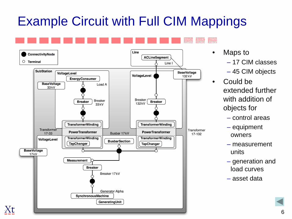
Example Circuit with Full CIM Mappings
• Maps to– 17 CIM classes– 45 CIM objects
• Could be extended further with addition of objects for
– control areas– equipment
owners– measurement
units– generation and
load curves– asset data

61970 Profiles Currently Defined
• Equipment – Identifies equipment, describes
basic characteristics, and electrical connectivity that would be input to topology processing
• Schedules – Describes input to functions
that derive parameters for a specific point in time
• Measurement Specs– Describes how SCADA will
obtain measurements and what equipment objects are measured
• Measurement Set– The set of SCADA values for
measurements for a particular point in time
• Topology– The result of topology
processing. i.e. Description of how equipment connects into buses and how buses makeup connected systems
• State Variables – Result of a state estimator or
power flow, or the starting conditions of state variables
• Dynamics– Adds dynamics to static
network model for running system simulations
• Schematic Layouts– Describes how equipment
objects are placed on schematic diagrams

61970-452 Static Transmission Network Model Profiles• Also known as Common Power System Model (CPSM)• Many Interoperability (IOP) tests since year 2000• In use in many countries• 61968-13 distribution model (CDPSM) based on these profiles as well
61970-451 Profile
61970-452Profiles
Equipment Model
61970-456 Profiles
Topology
State Variables
Schedules
Measurement and Control
Measurement Specifications
Connectivity
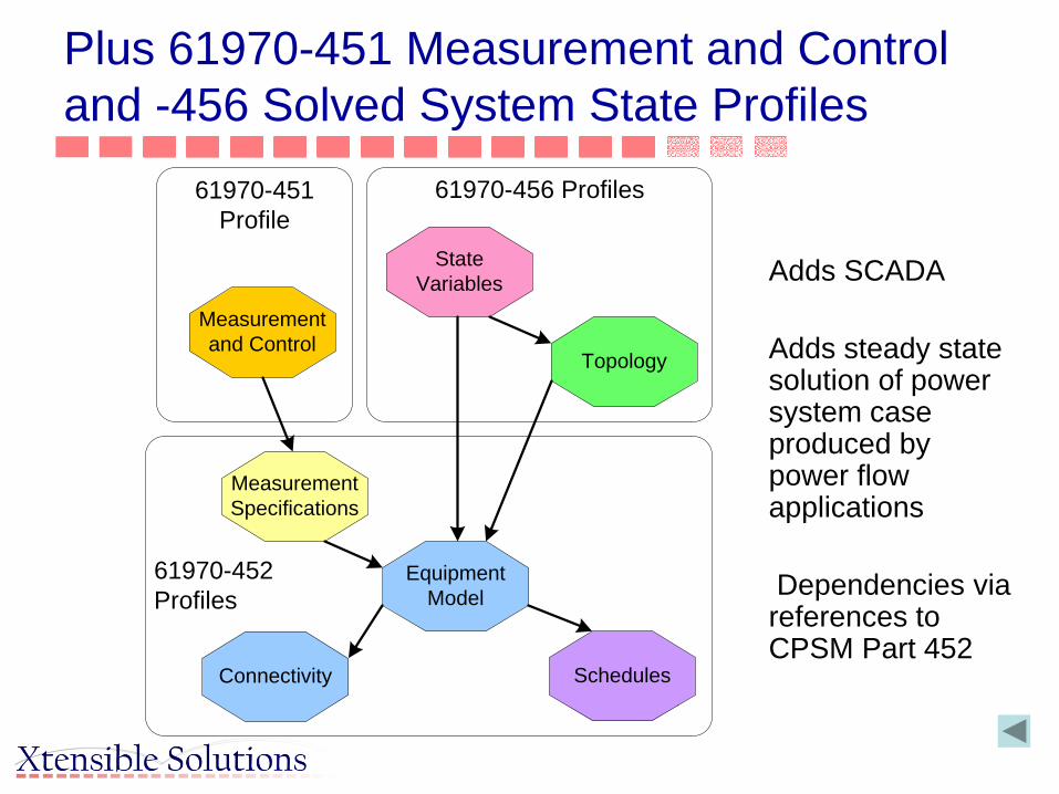
Plus 61970-451 Measurement and Control and -456 Solved System State Profiles
Adds SCADA
Adds steady state solution of power system case produced by power flow applications
Dependencies via references to CPSM Part 452

61970-451 Profile
61970-452Profiles
Equipment Model
61970-456 Profiles
Topology
State Variables
Schedules
Measurement and Control
Measurement Specifications
Connectivity
Plus 61970-451 Measurement and Control and -456 Solved System State Profiles
Adds dynamic models used in system simulation
Dependencies via references to CPSM Part 452

61970-451 Profile
61970-452Profiles
Equipment Model
61970-456 Profiles
Topology
State Variables
Schedules
Measurement and Control
Measurement Specifications
Connectivity
Plus 61970-451 Measurement and Control and -456 Solved System State Profiles
Adds diagram layout info for schematic data
Dependen- cies via reference to CPSM Part 452

Plus 61970-453 Diagram Layout Profile
61970-452Profiles
Equipment Model
61970-456 Profiles
Common Objects
Topology
State Variables
61970-453 Profile
Schedules
Diagram Layout
Measurement Set
Measurement Specifications
Boundary Objects
Future 61970-457 Profile
DynamicModels
Adds diagram layout info for schematic data
Dependen- cies via reference to CPSM Part 452
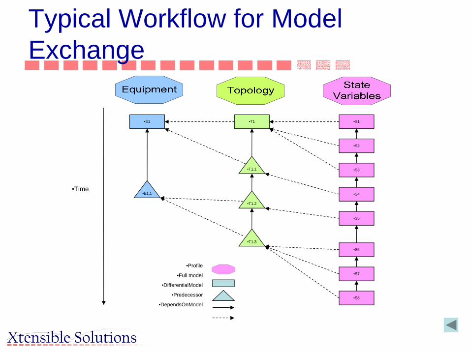
Typical Workflow for Model Exchange
•S1
•S2
•S3
•S4
•S5
•S6
•S7
•S8
•E1
•E1.1•Time
•T1
•Profile
•Full model
•DifferentialModel
•Predecessor
•DependsOnModel
•T1.1
•T1.3
•T1.2

TC57 CIM Standards for Power System Model Exchange
•CIM UML
•Information and Semantic Models
•Context
•Message Syntax
•Profiles
•Message/FileFormat
(XSD, RDFSchema, OWL)
•Contextual layer restricts information model• Specifies which part of CIM is used for given profile• Mandatory and optional• Restrictions• But cannot add to information model
•Message syntax describes format for instance data• Can re-label elements• Change associations to define single structure for
message payloads• Mappings to various technologies can be defined
• Information Model• Generalized model of all utility objects and their
relationships• Application independent, but defines all concepts
needed for any application
•Conforms to IEC 61970-301 CIM
•Conforms to collection of
Standard4xx Profiles
•Conforms to IEC 61970-552-4
CIM XML Model Exchange Format

15
Presentation Contents
• Profiles for business context– WG13 61970 Profiles for Power System Network
Model Exchange– WG14 61968 Message Payloads for System
Integration

From Information
Model to Syntactic
Model
AbstractModel
Syntactic Model
<?xml version="1.0" encoding="UTF-8"?><xsd:elementname=« MT_EnergyTransaction"><xsd:sequence>
<xsd:elementname=« EnergyTransaction"/>
<xsd:sequence><xsd:element name=« Name"/>
<xsd:element name=« Type"/></xsd:sequence>
</xsd:element>
UML World
XML Syntactic World
Information/SemanticModel
Context/Profiles
MessageAssembly
MessageSyntax
MeterReading &
Control
MeterReading &
Control
Utility ControlCenter
Utility ControlCenter
NetworkExpansionPlanning
NetworkExpansionPlanning
CustomerInquiry
CustomerInquiry
NetworkOperationNetwork
Operation
Records& Asset
Management
Records& Asset
Management
OperationalPlanning &
Optimization
OperationalPlanning &
Optimization
IEC 61968CompliantInterface
Architecture
IEC 61968CompliantInterface
Architecture
Maintenance&
Construction
Maintenance&
Construction
UtilityBusinessSystems
(ERP, Billing,Energy trading,other systems)
UtilityBusinessSystems
(ERP, Billing,Energy trading,other systems)
Corporate LAN
Corporate LAN
Distribution AutomationDistribution Automation
Substation Protection,Monitoring and Control
Substation Protection,Monitoring and Control
RTU Communications RTU Communications
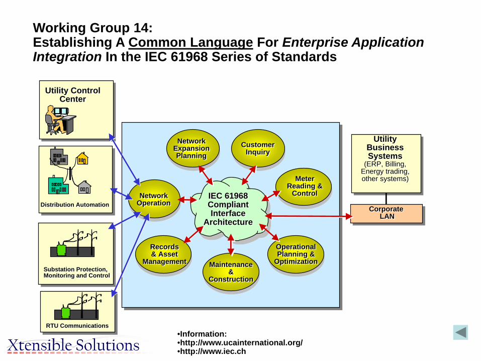
Working Group 14:Establishing A Common Language For Enterprise Application Integration In the IEC 61968 Series of Standards
•Information: •http://www.ucainternational.org/•http://www.iec.ch
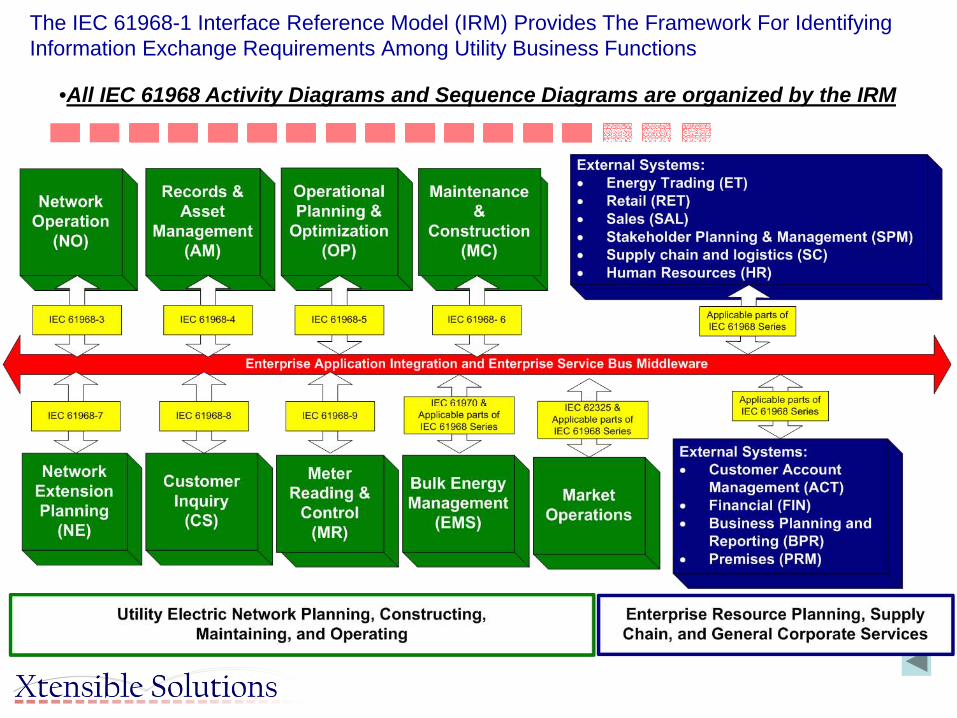
The IEC 61968-1 Interface Reference Model (IRM) Provides The Framework For Identifying Information Exchange Requirements Among Utility Business Functions
•All IEC 61968 Activity Diagrams and Sequence Diagrams are organized by the IRM

The Business Sub-Function Level of the IRM for IEC 61968 Scope
•Application Integration Infrastructure
•Network Operations•Network Operations•Monitoring (NMON)
•Network Control•(CTL)
•Fault Management•(FLT)
•Operational Feedback•Analysis (OFA)
•Operation Statistics•& Reporting (OST)
•Network Calculations•- Real Time (CLC)
•Records & Asset•Management
•Substation & Network•Inventory (EINV)
•Geographical•Inventory (GINV)
•Asset Investment•Planning (AIP)
•Operational Planning•& Optimization •Network Operation
•Simulation (SIM)
•Switch Action•Scheduling (SSC)
•Power Import Sched.•& Optimization (IMP)
•Maintenance and•Construction
•Maintenance &•Inspection (MAI)
•Construction WMS (CON)
•Design &•Estimate (DGN)
•Scheduling•& Dispatch (SCH)
•Field•Recording (FRD)
•Network Extension•Planning
•Network•Calculations (NCLC)
•Project Definition•(PRJ)
•Construction•Supervision (CSP)
•Compliance•Management (CMPL)
•Customer•Support
•Customer Service•(CSRV)
•Trouble Call•Management (TCM)
•Meter Reading & Control•Meter Reading•(RMR)
• External Systems
•Dispatcher Training (TRN) •General inventory
management (GIM)
•Load Control•(LDC)
•Meter Maintenance (MM)
•Meter Data (MD)
•Point Of Sale•(POS)
•Meter Operations•(MOP)
•Advanced Metering Infrastructure (AMI)
•Meter Data Management IMDM)
•Metering System•(MS)
•Demand Response•(DR)

The IEC 61968 Basic Message Structure

Message Header

IEC 61968-9: Interface Standard for Meter Reading and Control

Scope/Purpose
• To Define the exchange of information between a Metering System and other systems within the Utility enterprise
• Specifies the information content of a set of message types that can be used to support many of the business functions related to Merter Reading and Control.
• Typical uses of the message types include:– Meter Reading and Meter Control– Meter Events– Customer Data Synchronization and Customer Switching

Scope of Part 9
26
Enterprise Applications
Head End Systems
PAN
PANDevice
PANDevice
PAN
PANDevice
PANDevice
Meter
Meter or Gateway
Meter or Gateway
PANDevice
Electric Utility
Enterprise Integration Infrastructure
(e.g. ESB, SOA, …)
Standard or ProprietaryCommunicationInfrastructures
Messages defined by IEC 61968-9 and based upon
IEC CIM, conveyed using a variety of integration
technologies
IEC 61968-9 Messages
Messages defined by relevant standards or
vendors. May use a wide variety of communication
technologies
Messages defined by PAN/HAN specifications
Mappings, translations and/orforwardiing as
needed Mapping, translations and/or forwarding as
needed
Customer
Customer
Customer
Area of Direct Impact using IEC 61968-9
Area Causally/Indirectly Impacted by or impacting
IEC 61968-9
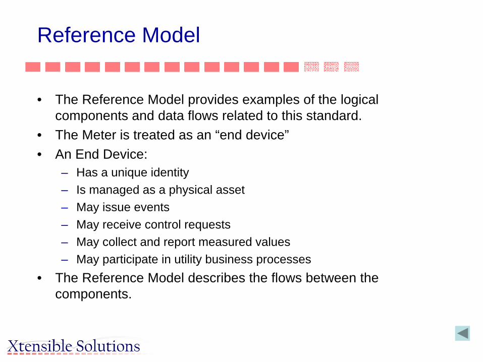
Reference Model
• The Reference Model provides examples of the logical components and data flows related to this standard.
• The Meter is treated as an “end device”• An End Device:
– Has a unique identity– Is managed as a physical asset– May issue events– May receive control requests– May collect and report measured values– May participate in utility business processes
• The Reference Model describes the flows between the components.

Part 9 Reference Model

Part 9 Message Types

Typical Message Payload Definition -EndDeviceEvent Message
EndDeviceEventMessages Convey events related to:• Sustained Outage
Detection• Momentary Outage
Detection• Low Voltage
Threshold Detection• High Voltage
Threshold Detection• Distortion Meter
Health• Tamper Detection• Revenue Event
30

31
Work Overview
Publication No. Description Status Responsible WG14 Lead
To IEC Next Step
61968-01 Interface Architecture and General Requirements
IS Shawn Hu July 2010 MCR
61968-01-1 ESB Implementation Profile
Working Draft
Scott Neumann July 2010 NWIP & CD
61968-01-2 Web Services Working Draft
Mark Ortiz July 2010 NWIP & CD
61968-02 Glossary Technical Report
David Haynes June 2009 MCR
61968-03 Network Operations IS Bruce Scovill July 2011 MCR
61968-04 Records & Asset Management
IS Jon Fairchild July 2011 MCR
•WG14 Status

32
Work Overview
Publication No.
Description Status Responsible WG14 Lead
To IEC Next Step
61968-05 Operational Planning and Optimization
Working Draft Jim Waight TBD Postponed until experts from 5 countries are provided. Also, part 5 should be based on the revised parts 3.
61968-06 Maintenance and Construction
Working Draft Nada Reinprecht
July 2011 NWIP & CD
61968-07 Network Extension Planning
Working Draft Jim Waight TBD Postponed until experts from 5 countries are provided. Also, part 7 should be based on the revised parts 3 & 4 and coordinated with part 6 and WG13.
61968-08 Customer Support NWIP & CD Larry Clark and Mark Ortiz
Sept 2010 Work to recast document to new format& issue CD. Get experts from 5 countries to develop CDV, which is due Dec 2011..
61968-09 Meter Reading and Control
IS Scott Neumann July 2011 MCR
•WG14 Status

33
Work Overview
Publication No. Description Status Responsible WG14 Lead
To IEC Next Step
61968-11 Common Information Model for DMS
FDIS Tanja Kostic March 2011 MCR
61968-12 Compliance and Interoperability Testing
Working Draft
Margaret Goodrich
As tests are performed
NWIP & Technical Report
61968-13 Common Distribution Power System Model
IS Eric Lambert January 2011 MCR
61968-14-1 Mapping between MultiSpeak 4.0 and IEC 61968, parts 3 through 10
Working Draft
Gary McNaughton
In planning and recruitment stage
61968-14-2 A CIM profile for MultiSpeak 4.0, one profile for IEC 61968 parts 3 through10
Working Draft
Gary McNaughton
In planning and recruitment stage
•WG14 Status

Next – Message Syntax
CIM UML
Information and Semantic Models
Context
Message Syntax
Profiles
Message/FileFormat
(XSD, RDFSchema, OWL)
Contextual layer restricts information model• Specifies which part of CIM is used for given profile• Mandatory and optional• Restrictions• But cannot add to information model
Message syntax describes format for instance data• Can re-label elements• Change associations to define single structure for
message payloads• Mappings to various technologies can be defined
Information Model• Generalized model of all utility objects and their
relationships• Application independent, but defines all concepts
needed for any application

35
Implementation Syntax – XML Schema
• XML Syntax• Example of use of XML Schema• Mapping Proprietary EMS Interfaces to the CIM
– Provide enterprise system access to transformer data
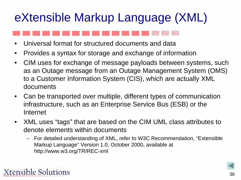
eXtensible Markup Language (XML)
• Universal format for structured documents and data• Provides a syntax for storage and exchange of information• CIM uses for exchange of message payloads between systems, such
as an Outage message from an Outage Management System (OMS) to a Customer Information System (CIS), which are actually XML documents
• Can be transported over multiple, different types of communication infrastructure, such as an Enterprise Service Bus (ESB) or the Internet
• XML uses “tags” that are based on the CIM UML class attributes to denote elements within documents
– For detailed understanding of XML, refer to W3C Recommendation, “Extensible Markup Language” Version 1.0, October 2000, available at http://www.w3.org/TR/REC-xml
36

37
Mapping CIM class structure to XML using XML Schema (XSD)
• An XML Schema of the CIM can be autogenerated from UML models with third party tools– A list and description of available tools is on the CIMug
SharePoint site• The CIM classes and attributes are used to define tags• Then the CIM can be shown in XML as well as UML • Example is PowerTransformer

38
Mapping EMS Interfaces to the CIM –User access to transformer data
• EMS Native Interface attributes:– TRANS_NAME – The Transformer’s name– WINDINGA_R – The Transformer’s primary winding resistance– WINDINGA_X – The Transformer’s primary winding reactance– WINDINGB_R – The Transformer’s secondary winding resistance– WINDINGB_X – The Transformer’s secondary winding reactance– WINDINGA_V – The Transformer’s primary winding voltage– WINDINGB_V – The Transformer’s secondary winding voltage

39
Transformer Class Diagram in CIM

40
CIM Interface Mapping- Beginnings of Profile/Message Payload Definition
Two different interface attributes (WINDINGA_R and WINDINGB_R) map to same
CIM attribute
Aggregation changed from 0..n to 2
Multiplicity changed from
0..1 to 1
Multiplicity changed from
0..1 to 1

41
Message Payload in UML
Note:• Associations changed to aggregations• Parent classes removed
• Not required in actual message content• Parent classes already known by both sender and receiver
• Corollary: Only those parts of the CIM used in message exchange need to be supported by interface applications
• End result – modified class structure• Example of application of business context to information model
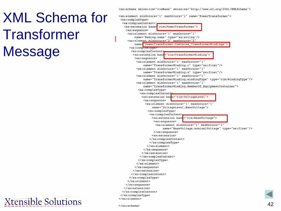
42
XML Schema for Transformer Message

43
Sample Transformer Interface Message Payload in XML
<cim:PowerTransformer> <cim:Naming.name>Transformer SGT1</cim:Naming.name> <cim:PowerTransformer.Contains_TransformerWindings> <cim:TransformerWinding.r>0.23</cim:TransformerWinding.r> <cim:TransformerWinding.x>0.78</cim:TransformerWinding.x> <cim:TransformerWinding.windingType>WindingType.primary </cim:TransformerWinding.windingType> <cim:Equipment.MemberOf_EquipmentContainer> <cim:VoltageLevel.BaseVoltage> <cim:BaseVoltage.nominaVoltage>400 </cim:BaseVoltage.nominalVoltage> </cim:VoltageLevel.BaseVoltage> </cim:Equipment.MemberOf_EquipmenContainer> </cim:PowerTransformer.Contains_TransformerWindings> <cim:PowerTransformer.Contains_TransformerWindings> <cim:TransformerWinding.r>0.46</cim:TransformerWinding.r> <cim:TransformerWinding.x>0.87</cim:TransformerWinding.x> <cim:TransformerWinding.windingType>WindingType.secondary </cim:TransformerWinding.windingType> <cim:Equipment.MemberOf_EquipmentContainer> <cim:VoltageLevel.BaseVoltage> <cim:BaseVoltage.nominaVoltage>275 </cim:BaseVoltage.nominalVoltage> </cim:VoltageLevel.BaseVoltage> </cim:Equipment.MemberOf_EquipmenContainer> </cim:PowerTransformer.Contains_TransformerWindings>
</cim:PowerTransformer>
44
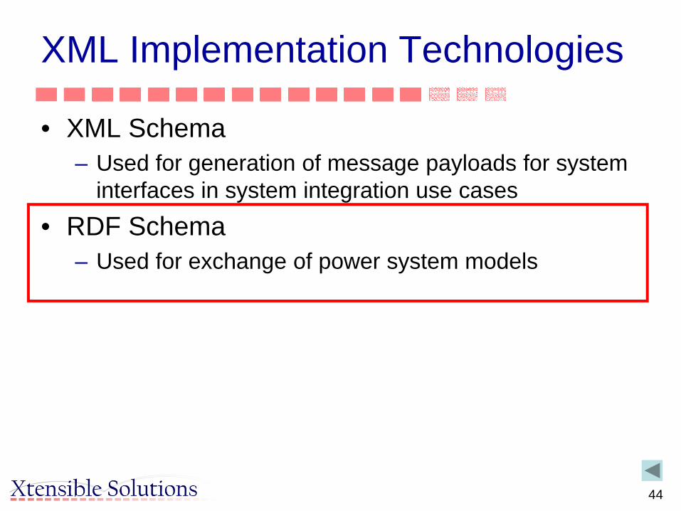
XML Implementation Technologies
• XML Schema– Used for generation of message payloads for system
interfaces in system integration use cases• RDF Schema
– Used for exchange of power system models

45
Big Issue
• “Although we can swap our documents with each other through XML, we still haven’t a clue what they mean.”
» (“Professional XML Meta Data,” by Kal Ahmed, et al.)
• Resource Description Framework (RDF) Is W3C’s Means To Resolve This.
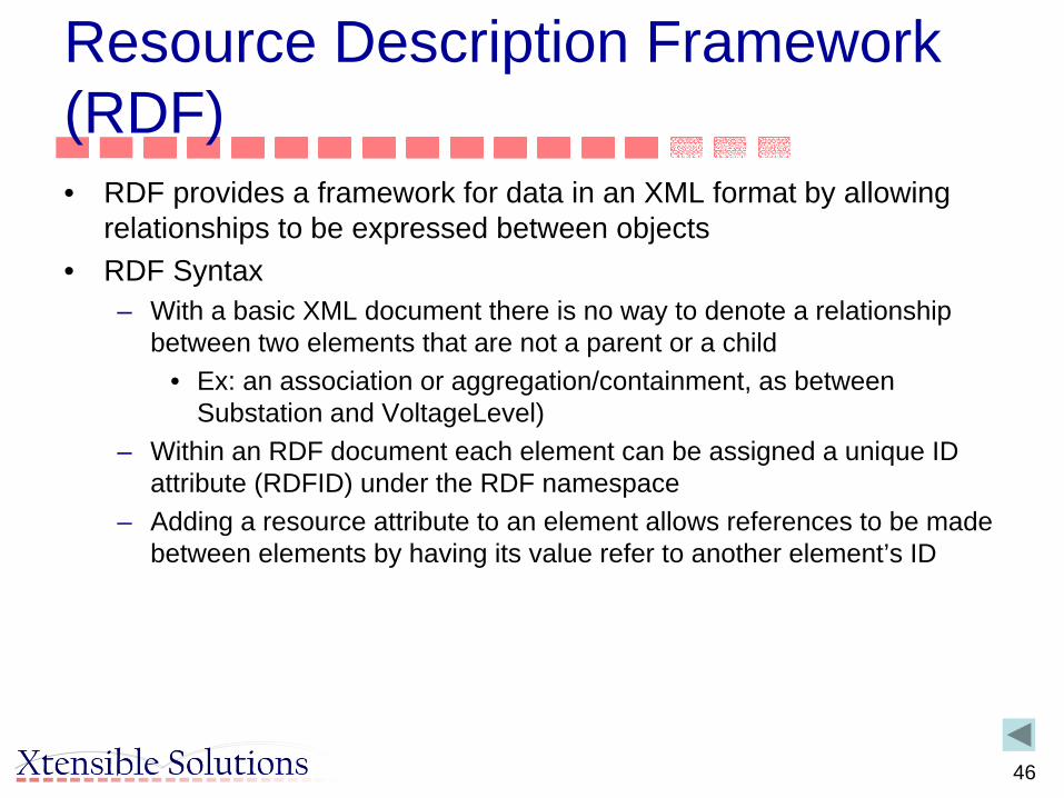
Resource Description Framework (RDF)• RDF provides a framework for data in an XML format by allowing
relationships to be expressed between objects• RDF Syntax
– With a basic XML document there is no way to denote a relationship between two elements that are not a parent or a child
• Ex: an association or aggregation/containment, as between Substation and VoltageLevel)
– Within an RDF document each element can be assigned a unique ID attribute (RDFID) under the RDF namespace
– Adding a resource attribute to an element allows references to be made between elements by having its value refer to another element’s ID
46

RDF Schema• While RDF provides a means of expressing simple statements about
the relationship between resources, it does not define the vocabulary of these statements
• The RDF Vocabulary Description Language, known as RDF• Schema (RDFS) provides the user with a means of describing
specific kinds of resources or classes• RDFS does not provide a vocabulary for a specific application's
classes, but instead allows the user to describe these classes and properties themselves and indicate when they should be used together
– Semantics contained in the CIM UML model provide the vocabulary
• RDF combined with RDF Schema– Provides a mechanism for expressing a basic class hierarchy as an XML schema
by specifying the basic relationship between classes and propertie– This allows a set of objects to be expressed as XML using a defined schema that
retain their relationships and class hierarchy
47

48
References• RDF (Resource Description Framework)
– For more information: http://www.w3.org/RDF– Status: W3C Recommendation 2004-02-10– List of documents at: http://www.w3.org/standards/techs/rdf
• RDF Schema– Status: W3C Recommendation 2004-02-10
• http://www.w3.org/TR/PR-rdf-schema• Namespaces
– Provides a simple method for qualifying element and attribute names used in XML documents by associating them with namespaces identified by URI references
– Status: WC3 Recommendation 2009-12-08• http://www.w3.org/TR/REC-xml-names
• URI (Uniform Resource Identifiers)– Provides a simple and extensible means for identifying a resource– Status: Internet RFC August 1998
• http://www.w3.org/Addressing/

Mapping CIM Class Structure to XML using RDF Schema• Commonly referred to as “CIM/XML” but correct reference is CIM
RDF XML• 61970-501 specifies the mapping between CIM UML model defined in
61970-301 into a machine readable format as expressed in the XML representation of that schema using the RDF Schema specification language– The resulting CIM RDF schema supports CIM Model Exchange profiles,
as presented in IEC 61970-452 and others– Allows CIM data objects to be mapped, one-to-one, into RDF instance
data. • Part 501 specifies the subset of RDF used for CIM RDF XML
– Any RDF parser can be used to read CIM RDF XML– CIM community developed tools to auto-generate the CIM RDF XML from
the CIM UML model
49

50
Simple Network Example
SS1
SS2
400KV
110KV
12345 MW
12345 KV
12345 MW
Cable1 Cable2
SS1-SS2
T1
BB1
SS4
Cable3

51
Simple Network Connectivity Modeled with CIM Topology
SS 1
Cable2
SS 2
110KV
400KV
Cable1 CN2CN3BR1DC2 CN4
P1(MW)
CN5
BB1
T 1
TW 1
TW 2
CN7
CN6
Volts(KV)
BR3
P2(MW)
CN1
SS1-SS2
Cable3
SS 4
CN8
BDD-RSK2
T1 T2
52
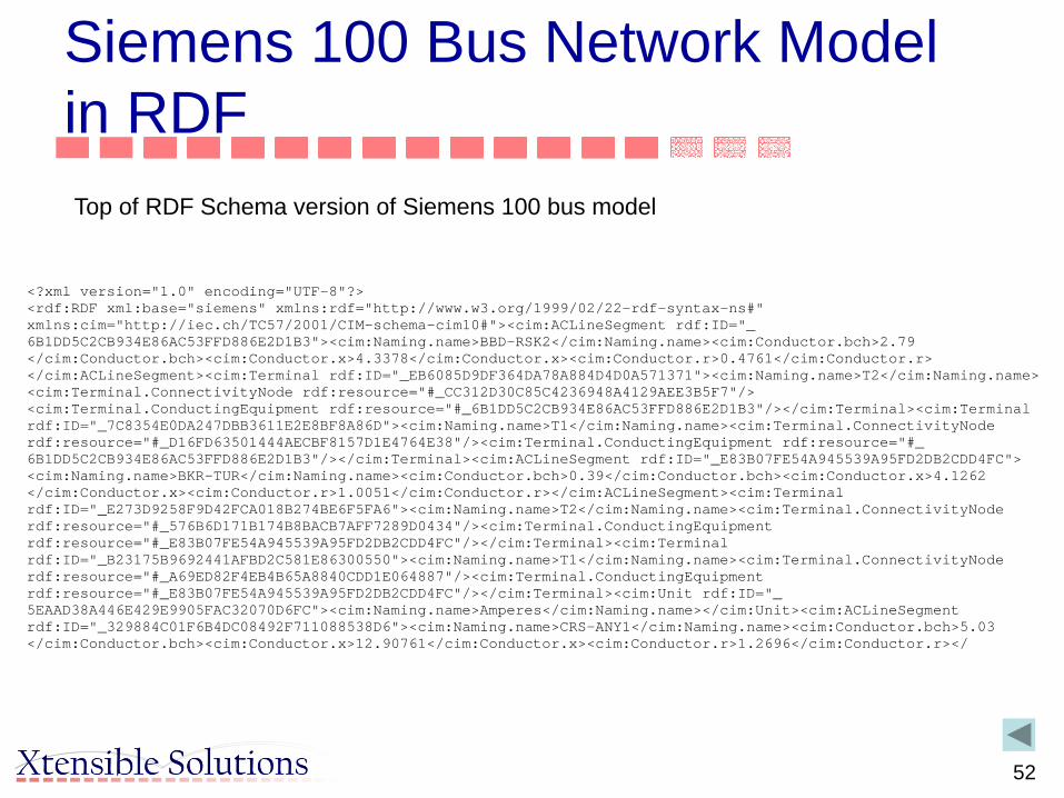
Siemens 100 Bus Network Model in RDF
<?xml version="1.0" encoding="UTF-8"?><rdf:RDF xml:base="siemens" xmlns:rdf="http://www.w3.org/1999/02/22-rdf-syntax-ns#" xmlns:cim="http://iec.ch/TC57/2001/CIM-schema-cim10#"><cim:ACLineSegment rdf:ID="_6B1DD5C2CB934E86AC53FFD886E2D1B3"><cim:Naming.name>BBD-RSK2</cim:Naming.name><cim:Conductor.bch>2.79</cim:Conductor.bch><cim:Conductor.x>4.3378</cim:Conductor.x><cim:Conductor.r>0.4761</cim:Conductor.r></cim:ACLineSegment><cim:Terminal rdf:ID="_EB6085D9DF364DA78A884D4D0A571371"><cim:Naming.name>T2</cim:Naming.name><cim:Terminal.ConnectivityNode rdf:resource="#_CC312D30C85C4236948A4129AEE3B5F7"/><cim:Terminal.ConductingEquipment rdf:resource="#_6B1DD5C2CB934E86AC53FFD886E2D1B3"/></cim:Terminal><cim:Terminal rdf:ID="_7C8354E0DA247DBB3611E2E8BF8A86D"><cim:Naming.name>T1</cim:Naming.name><cim:Terminal.ConnectivityNode rdf:resource="#_D16FD63501444AECBF8157D1E4764E38"/><cim:Terminal.ConductingEquipment rdf:resource="#_6B1DD5C2CB934E86AC53FFD886E2D1B3"/></cim:Terminal><cim:ACLineSegment rdf:ID="_E83B07FE54A945539A95FD2DB2CDD4FC"><cim:Naming.name>BKR-TUR</cim:Naming.name><cim:Conductor.bch>0.39</cim:Conductor.bch><cim:Conductor.x>4.1262</cim:Conductor.x><cim:Conductor.r>1.0051</cim:Conductor.r></cim:ACLineSegment><cim:Terminal rdf:ID="_E273D9258F9D42FCA018B274BE6F5FA6"><cim:Naming.name>T2</cim:Naming.name><cim:Terminal.ConnectivityNode rdf:resource="#_576B6D171B174B8BACB7AFF7289D0434"/><cim:Terminal.ConductingEquipment rdf:resource="#_E83B07FE54A945539A95FD2DB2CDD4FC"/></cim:Terminal><cim:Terminal rdf:ID="_B23175B9692441AFBD2C581E86300550"><cim:Naming.name>T1</cim:Naming.name><cim:Terminal.ConnectivityNode rdf:resource="#_A69ED82F4EB4B65A8840CDD1E064887"/><cim:Terminal.ConductingEquipment rdf:resource="#_E83B07FE54A945539A95FD2DB2CDD4FC"/></cim:Terminal><cim:Unit rdf:ID="_5EAAD38A446E429E9905FAC32070D6FC"><cim:Naming.name>Amperes</cim:Naming.name></cim:Unit><cim:ACLineSegment rdf:ID="_329884C01F6B4DC08492F711088538D6"><cim:Naming.name>CRS-ANY1</cim:Naming.name><cim:Conductor.bch>5.03</cim:Conductor.bch><cim:Conductor.x>12.90761</cim:Conductor.x><cim:Conductor.r>1.2696</cim:Conductor.r></
Top of RDF Schema version of Siemens 100 bus model

53
ACLineSegment in RDF
Siemens 100 bus model - RDF schema
<?xml version="1.0" encoding="UTF-8"?><rdf:RDF xml:base="siemens" xmlns:rdf="http://www.w3.org/1999/02/22-rdf-syntax-ns#" xmlns:cim="http://iec.ch/TC57/2001/CIM-schema-cim10#">
<cim:ACLineSegment rdf:ID="_6B1DD5C2CB934E86AC53FFD886E2D1B3"><cim:Naming.name>BBD-RSK2</cim:Naming.name><cim:Conductor.bch>2.79</cim:Conductor.bch><cim:Conductor.x>4.3378</cim:Conductor.x><cim:Conductor.r>0.4761</cim:Conductor.r>
</cim:ACLineSegment>
<cim:Terminal rdf:ID="_EB6085D9DF364DA78A884D4D0A571371"><cim:Naming.name>T2</cim:Naming.name><cim:Terminal.ConnectivityNode rdf:resource="#_CC312D30C85C4236948A4129AEE3B5F7"/><cim:Terminal.ConductingEquipment rdf:resource="#_6B1DD5C2CB934E86AC53FFD886E2D1B3"/>
</cim:Terminal>
<cim:Terminal rdf:ID="_7C8354E0DA247DBB3611E2E8BF8A86D"><cim:Naming.name>T1</cim:Naming.name><cim:Terminal.ConnectivityNode rdf:resource="#_D16FD63501444AECBF8157D1E4764E38"/><cim:Terminal.ConductingEquipment rdf:resource="#_6B1DD5C2CB934E86AC53FFD886E2D1B3"/>
</cim:Terminal>

54
ACLineSegment in RDF
Siemens 100 bus model - RDF schema
<?xml version="1.0" encoding="UTF-8"?><rdf:RDF xml:base="siemens" xmlns:rdf="http://www.w3.org/1999/02/22-rdf-syntax-ns#" xmlns:cim="http://iec.ch/TC57/2001/CIM-schema-cim10#">
<cim:ACLineSegment rdf:ID="_6B1DD5C2CB934E86AC53FFD886E2D1B3"><cim:Naming.name>BBD-RSK2</cim:Naming.name><cim:Conductor.bch>2.79</cim:Conductor.bch><cim:Conductor.x>4.3378</cim:Conductor.x><cim:Conductor.r>0.4761</cim:Conductor.r>
</cim:ACLineSegment>
<cim:Terminal rdf:ID="_EB6085D9DF364DA78A884D4D0A571371"><cim:Naming.name>T2</cim:Naming.name><cim:Terminal.ConnectivityNode rdf:resource="#_CC312D30C85C4236948A4129AEE3B5F7"/><cim:Terminal.ConductingEquipment rdf:resource="#_6B1DD5C2CB934E86AC53FFD886E2D1B3"/>
</cim:Terminal>
<cim:Terminal rdf:ID="_7C8354E0DA247DBB3611E2E8BF8A86D"><cim:Naming.name>T1</cim:Naming.name><cim:Terminal.ConnectivityNode rdf:resource="#_D16FD63501444AECBF8157D1E4764E38"/><cim:Terminal.ConductingEquipment rdf:resource="#_6B1DD5C2CB934E86AC53FFD886E2D1B3"/>
</cim:Terminal>

55
Containment in RDFSubstation VOL with 230 KV voltage level and Bay 240W79 with Breaker CB
<cim:Substation rdf:ID="_277B2933524E43E19DAAF1D138DC62C4"><cim:Naming.name>VOL</cim:Naming.name><cim:Substation.LoadArea rdf:resource="#_BA2173878B0645A7AC8EA57B6249D537"/>
</cim:Substation>
<cim:VoltageLevel rdf:ID="_C20AF84C15E047218D75C47870C34C87"><cim:Naming.name>230K</cim:Naming.name><cim:VoltageLevel.MemberOf_Substation rdf:resource="#_277B2933524E43E19DAAF1D138DC62C4"/><cim:VoltageLevel.BaseVoltage rdf:resource="#_CF8BD1450E264399891F7FE5653D0760"/>
</cim:VoltageLevel>
<cim:BusbarSection rdf:ID="_5E0DBC09FE4D4A0DB902FEFF18AA4C30"><cim:Naming.name>VOL 2304</cim:Naming.name><cim:Equipment.MemberOf_EquipmentContainer rdf:resource="#_C20AF84C15E047218D75C47870C34C87"/>
</cim:BusbarSection>
Further down in document
Substation VOL with 230 KV voltage level and Bay 240W79 with Breaker CB
<cim:Bay rdf:ID="_7DBBA5E32C834B6AB08BB6FB07155D46"><cim:Naming.name>240W79</cim:Naming.name><cim:Bay.MemberOf_VoltageLevel rdf:resource="#_C20AF84C15E047218D75C47870C34C87"/>
</cim:Bay>
<cim:Breaker rdf:ID="_4A74B55420834E40B85F0304B6F9ADF8"><cim:Naming.name>CB</cim:Naming.name><cim:Switch.normalOpen>false</cim:Switch.normalOpen><cim:Equipment.MemberOf_EquipmentContainer rdf:resource="#_7DBBA5E32C834B6AB08BB6FB07155D46"/>
</cim:Breaker>
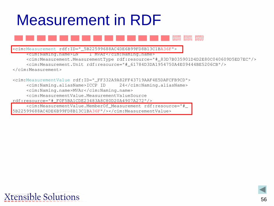
56
Measurement in RDF<cim:Measurement rdf:ID="_5B22599688AC4DE6B99FD8B13C1BA36F">
<cim:Naming.name>LN 1 MVAr</cim:Naming.name><cim:Measurement.MeasurementType rdf:resource="#_83D7B035901D4D2E80C040609D5ED7EC"/><cim:Measurement.Unit rdf:resource="#_61784D3DA1954750A4E09444BE5206CB"/>
</cim:Measurement>
<cim:MeasurementValue rdf:ID="_FF332A9A82FF43719AAF4E5DAFCFB9CD"><cim:Naming.aliasName>ICCP ID 24</cim:Naming.aliasName><cim:Naming.name>MVAr</cim:Naming.name><cim:MeasurementValue.MeasurementValueSource
rdf:resource="#_F0F5BA1CDE23483A8C80D20A4907A272"/><cim:MeasurementValue.MemberOf_Measurement rdf:resource="#_
5B22599688AC4DE6B99FD8B13C1BA36F"/></cim:MeasurementValue>

57
Implementation Syntax – WG13 61970
• Part 552 describes the CIM XML format at a level for implementation to support the model exchange requirements in IEC 61970-452
– This standard relies upon the CIM RDF Schema of IEC 61970-501
– Includes Difference model– Includes file header specification with file dependencies to for
importer to ensure all prerequisite models exist prior to importing

58
Basics: Schema from CIM
EnterpriseArchitect
CIM (in UML)
UMLto RDF
Transformers
CIM asXML/RDFSchema
specifies
PowerSystem Data
Exporter
PowerSystem Data
as XML/RDF

59
How Are CIM Standards Used?
• Unlike most standards we use– Ex: ICCP/TASE.2 Communication Protocol standard– Fixed functionality, very stable, easy to test compliance, but inflexible
• CIM standards can be strictly applied and tested for compliance– Ex: CIM/XML Power system model exchange– Product interfaces can be developed and tested for compliance– Subject of several EPRI-sponsored interoperability tests for specific
interface definition

60
Example: Power Flow Network Model Exchange
CIM UML
Information and Semantic Models
Context
Message Syntax
Power SystemModel Profile
Group
CIM/RDFSchema
Information Model• Defines all concepts needed for
exchange of operational load flow models
– Reused parts– New extensions
Contextual layer restricts information model• Specifies which part of CIM is used for
static/dynamic model exchange• Mandatory and optional• Restrictions• But cannot add to information model
File syntax• Can re-label elements• Change associations to define single
structure for message payloads• Mappings to various technologies can
be defined
Conforms to IEC 61970-301 CIM
Conforms to IEC 61970-452, 453,
456, othersModel Exchange
Profile
Conforms to IEC 61970-501 and -552
CIM XML Model Exchange Format
61
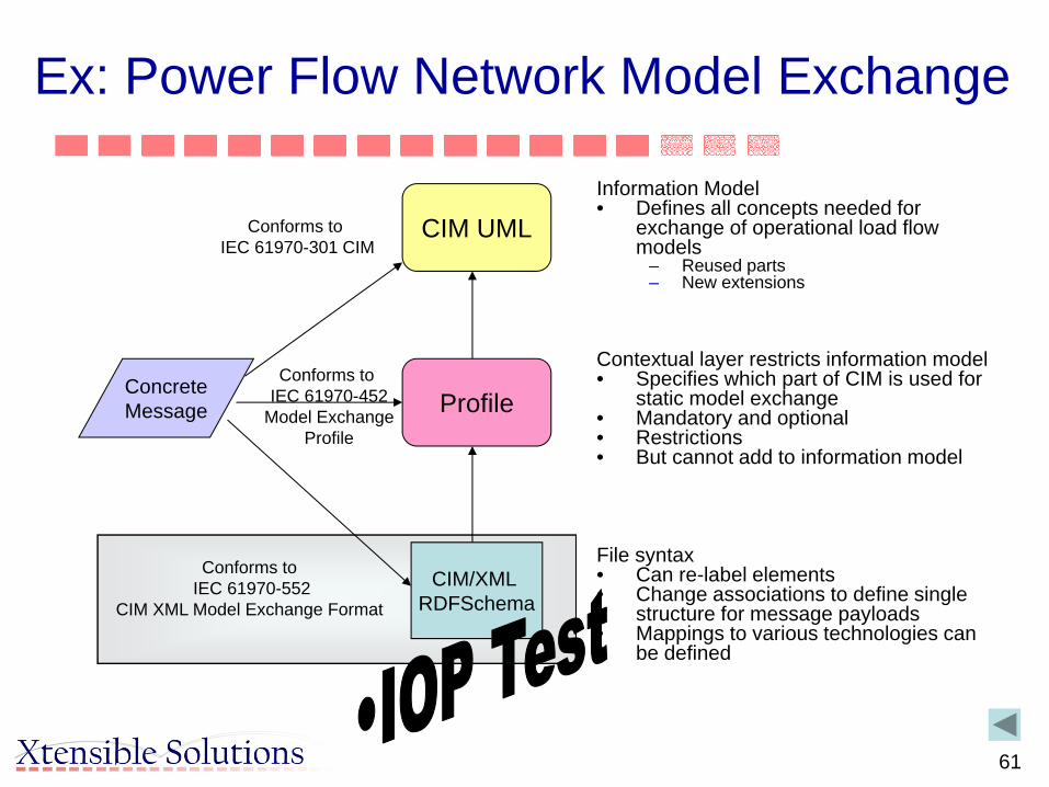
Ex: Power Flow Network Model Exchange
Information Model• Defines all concepts needed for
exchange of operational load flow models
– Reused parts– New extensions
Contextual layer restricts information model• Specifies which part of CIM is used for
static model exchange• Mandatory and optional• Restrictions• But cannot add to information model
File syntax• Can re-label elements• Change associations to define single
structure for message payloads• Mappings to various technologies can
be defined
CIM UML
Profile
CIM/XML RDFSchema
ConcreteMessage
Conforms to IEC 61970-301 CIM
Conforms to IEC 61970-452
Model ExchangeProfile
Conforms to IEC 61970-552
CIM XML Model Exchange Format

62
How Are CIM Standards Used?
• Unlike most standards that we are used to– Ex: IDDP/TASE.2 Communication Protocol standard– Fixed functionality, very stable, easy to test compliance, but inflexible
• CIM standards can be strictly applied and tested for compliance– Ex: CIM/XML Power system model exchange– Product interfaces can be developed and tested for compliance– Subject of several EPRI-sponsored interoperability tests for specific
interface definition• CIM can also be used as a starter kit
– Basis for an Enterprise Semantic Model (ESM) which includes other models/semantics from other sources
– Ex: Sempra Information Model (SIM)– Interfaces are usually project-defined, so no standard tests– System interfaces are managed and tested for each project
63
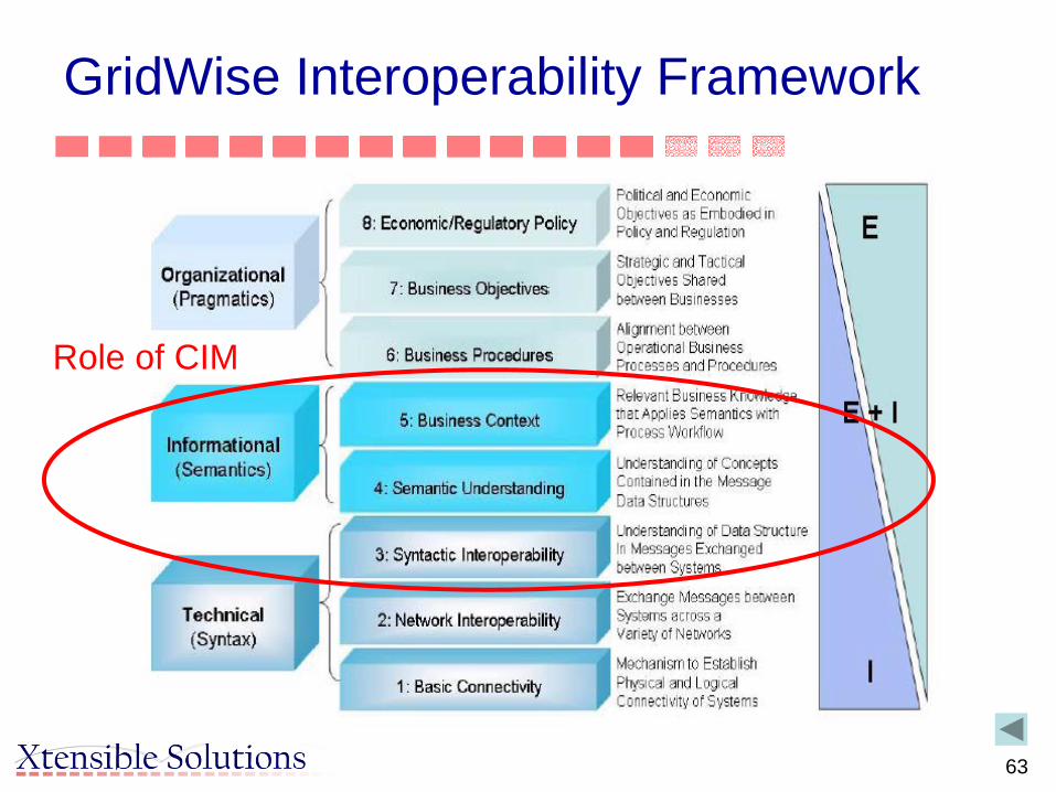
GridWise Interoperability Framework
Role of CIM
64
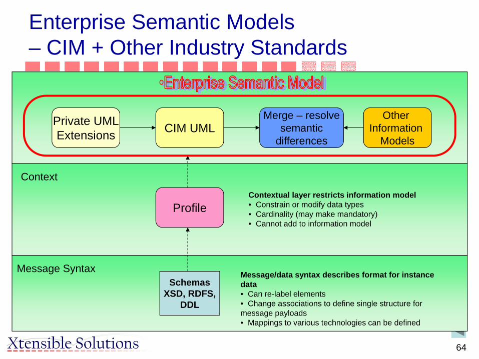
Enterprise Semantic Models– CIM + Other Industry Standards
CIM UMLPrivate UMLExtensions
Merge – resolvesemantic
differences
Other Information
Models
Context
Message Syntax
Profile
SchemasXSD, RDFS,
DDL
Contextual layer restricts information model• Constrain or modify data types• Cardinality (may make mandatory)• Cannot add to information model
Message/data syntax describes format for instance data• Can re-label elements• Change associations to define single structure for message payloads• Mappings to various technologies can be defined
65
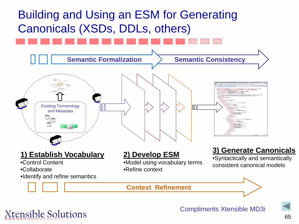
3) Generate Canonicals•Syntactically and semantically consistent canonical models
Semantic Consistency
1) Establish Vocabulary•Control Content•Collaborate•Identify and refine semantics
Semantic Formalization
Context Refinement
2) Develop ESM•Model using vocabulary terms•Refine context
Existing Terminologyand Metadata
Building and Using an ESM for GeneratingCanonicals (XSDs, DDLs, others)
Compliments Xtensible MD3i

66
Role of Enterprise Semantic Model
Enterprise Integration Platforms
Application Information
Process Integration
Business Intelligence
BPM/Workflow
EnterpriseSemantic
Model
Open Standards
ApplicationsMetadata
Bus
ines
sD
efin
ition
s

67
Let’s Apply to a Utility Project- Interface Architecture
CIM UMLCIM UMLExtensions
Context
Interface Syntax
Profile 1
MessageXML Schema
Profile 2
CIM/RDFSchema
Profile 3
DDL
BridgeOther
Information Models
System Interface Design
Document
Profile 1Profile 1

68
Ex: Project Interaction Test
Enterprise Semantic Model• Defines all concepts needed for
Enterprise– Reused parts– New extensions for project
ESM
Profile
XML Schema
ConcreteMessage
Conforms to Utility ESM
Conforms to Profiles defined
for each system interaction
Conforms to WSDLs and Message
XML Schemas
Contextual layer restricts ESM• Specifies which part of ESM is used for
specific system interaction• Mandatory and optional• Restrictions• But cannot add to information model
File syntax• Can re-label elements• Change associations to define single
structure for message payloads• Mappings to various technologies can
be defined
69
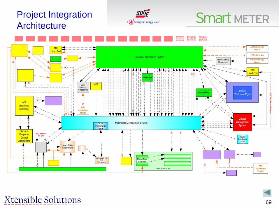
Project Integration Architecture
70
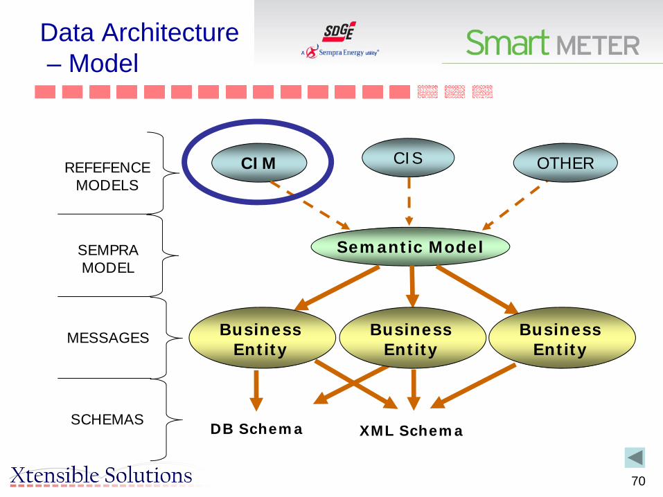
Data Architecture– Model
CIM
Semantic Model
XML SchemaDB Schema
CIS OTHERREFEFENCE MODELS
SEMPRA MODEL
MESSAGES
SCHEMAS
Business Entity
Business Entity
Business Entity

71
Use of ESM to Implement a Service Oriented Architecture (SOA)
• CAISO designed a new power market system– Multi-year program that involved many vendors, new systems, as
well as numerous legacy systems• Includes EMS, Full Network Model, Outage Management, PI
Historian, Market Systems, many others• External interfaces to Market Participants included
• Integration Competency Center decided on a Service Oriented Architecture (SOA) for the integration framework– Require all new applications and systems to be “Integration
Ready” with service-enabled interfaces– Use only standard CAISO-defined services– Payloads based on the CIM– Based on Web services– CIM and Model Driven Integration (MDI) methodology used to
define information exchange
72
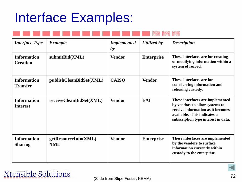
Interface Examples:Interface Type Example Implemented
byUtilized by Description
Information Creation
submitBid(XML) Vendor Enterprise These interfaces are for creating or modifying information within a system of record.
Information Transfer
publishCleanBidSet(XML) CAISO Vendor These interfaces are for transferring information and releasing custody.
Information Interest
receiveCleanBidSet(XML) Vendor EAI These interfaces are implemented by vendors to allow systems to receive information as it becomes available. This indicates a subscription type interest in data.
Information Sharing
getResourceInfo(XML) XML
Vendor Enterprise These interfaces are implemented by the vendors to surface information currently within custody to the enterprise.
(Slide from Stipe Fustar, KEMA)

73
System A Integration Layer
PI
BITS
MC
broadcastMarketMeterDataWS
retrieveMarketMeterData WS
broadcastMarketMeterData
WSretrieveMarketInterchange
WS
receiveMarketMeterDataWS
receiveMarketMeterDataWS
broadcastInvoiceData WS
broadcastGeneralLedgerData WS
receiveInvoiceData WS
receiveGeneralLedgerData WS
broadcastStatusInvoiceDataWS
(Slide from Stipe Fustar, KEMA)

74(Slide from Stipe Fustar, KEMA)

75(Slide from Stipe Fustar, KEMA)

76
CAISO Project Statistics22 Systems• Dispatch System• MP Report Interface• Load Forecast• Transmission Capacity
Calculator• Real Time Nodal System• Settlement and Market
Clearing• Bid Interface and Validation
7 Vendors• Siemens - Market Systems• ABB - EMS system• Areva - Settlement System• Legacy - CAISO system• Nexant - Congestion
Revenue Rights System• MCG - Interchange
Scheduling System• Potomac - Default Energy
Bids
• Default Energy Bids• Real Time Metering• Adjusted Metering• Market Participants
– Bidding– Market Results– Settlement– Outage Scheduling– Dispatch Signals
• Forward Market NodalSystem
• EMS
• OASIS• Interchange Scheduling
System• Congestion Revenue Rights• Intermittent Resources• Compliance• RMR Validation• Generation Outage Scheduling• Transmission Outage
Scheduling• Market Quality System
(ATF updates)
Appr 130 integrations between the 22 systemsAppr 75 message schemasAppr 175 service definitionsAppr 450 publisher/consumer testable data transfers
between systems
77
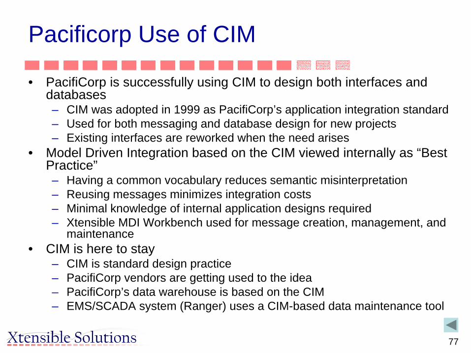
Pacificorp Use of CIM
• PacifiCorp is successfully using CIM to design both interfaces and databases– CIM was adopted in 1999 as PacifiCorp’s application integration standard – Used for both messaging and database design for new projects– Existing interfaces are reworked when the need arises
• Model Driven Integration based on the CIM viewed internally as “Best Practice”– Having a common vocabulary reduces semantic misinterpretation– Reusing messages minimizes integration costs– Minimal knowledge of internal application designs required– Xtensible MDI Workbench used for message creation, management, and
maintenance • CIM is here to stay
– CIM is standard design practice– PacifiCorp vendors are getting used to the idea– PacifiCorp’s data warehouse is based on the CIM– EMS/SCADA system (Ranger) uses a CIM-based data maintenance tool

78
CIM Scorecard – Examples of CIM useBusiness Units
Application/Project
Message(s) CIM Pct of message that is CIM
Power Delivery
Substation Measurements
IntervalRead, SubstationEquipment.Measurement MeasurementList 90%
Outage Center Call Handing
TroubleCalls, TroubleReportAlerts, TroubleReportDetails, TroubleReportSummary, Customer Info, Customer Balance, Customer Account Balance
OutageManagement 80%
Retail Access Project
RegisterReadRequest, BillDeterminant, CustDrop, Enroll.DACust, EnrollmentChange, NonDACust, Reg.ESSRegister, Register.ESS, ESStatusChange, SESSESSRelationshipChange, RegisterReadResponse, CnIConsumption, DAEnrollConsumption, EnrollmentChange, NonDAEnrollConsumption, ESSStatusChange
CustomerMeterDataSet,CustomerServiceAgreement,MeasurmentList,Document, ActivityRecord, CustomerBilling, BillingDeterminant
80%
Pole Attachment System
FacilityPoint, JointUse.Agreement, JointUse.Attachment, JointUse.Notice, JointNoticeRequest, FacilityPoint
AssetList 70%
Transmission Transmission Planned Outages
PlannedOutage.Change PlannedOutageNotification 50%
Transmission Wholesale Billing System
TransmissionData, STLossData, LTLossData, Scheduling.LoadData,ConsumptionData, InvoiceData
Settlement and MarketClearing 70%
EMS SCADA WeatherData MeasurementList 100%
79
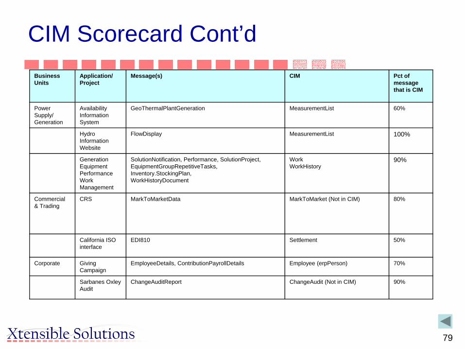
CIM Scorecard Cont’dBusiness Units
Application/Project
Message(s) CIM Pct of message that is CIM
Power Supply/Generation
Availability Information System
GeoThermalPlantGeneration MeasurementList 60%
Hydro Information Website
FlowDisplay MeasurementList 100%
Generation Equipment Performance Work Management
SolutionNotification, Performance, SolutionProject, EquipmentGroupRepetitiveTasks, Inventory.StockingPlan, WorkHistoryDocument
WorkWorkHistory
90%
Commercial & Trading
CRS MarkToMarketData MarkToMarket (Not in CIM) 80%
California ISO interface
EDI810 Settlement 50%
Corporate Giving Campaign
EmployeeDetails, ContributionPayrollDetails Employee (erpPerson) 70%
Sarbanes Oxley Audit
ChangeAuditReport ChangeAudit (Not in CIM) 90%

80
CIM Usage• Many EMS vendors support power system model exchange using CIM/RDF/XML,
some with CIM-based databases behind the scenes• EPRI has sponsored 12 interoperability tests for transmission model exchange and
service validation and more recently for planning and distribution• Utilities have implemented CIM-based integration using EAI technologies
– Utilities have used the CIM as the basis for developing common messages for integration• Asset and work management vendors as well as GIS application vendors are
supporting CIM/XSD standards• AMI (Smart Meter) projects use IEC 61968 Part 9 for meter related information
exchange• CIM has been extended into the power market, planning, and dynamic model
exchange• CIM provides a foundation for Service-Oriented Architecture (SOA) and Web service
implementations• Vendors have developed tools to build CIM-based information exchange messaging,
ESB and OPC interfaces, and repository applications that can process CIM-aware data• MultiSpeak is converting to CIM-based UML models and XML• ENTSO_E is converting power model exchanges and day-ahead forecasts for
planning/operational applications to CIM based format– Third IOP conducted in July 2011 (first was UCTE IOP in March 2009)
• Many Smart Grid-related activities based on CIM– Separate presentations during week

81
CIM Acceptance• In use at hundreds of utilities throughout world
– Used at TSOs, RTO/ISOs, IOUs, and Distribution Utilities– In Europe now being adopted by ENTSO-E and TOs
• 80+ applications support CIM standards• 60+ suppliers sell application/products based on CIM
– Based on 2007 CIM Reference List published by EPRI• Endorsed and used by other standards organizations
– Multispeak, Zigbee, HAN, ENTSO-E, NASBE, OASIS, etc. • Foundation for information exchange between utilities and/or other
external organizations• Foundation for Model-Driven Integration (MDI) architecture based on
an Enterprise InformatiSemantic Model (ESM) within an enterprise• Key building block in Smart Grid to achieve interoperability
– 61968/70 are top 2 of 5 priority standards recognized by NIST & FERC in North America
• CIM User Group to deal with questions and issues arising from increased use

83
Where to Get More Information About the CIM and Related Standards• Visit CIM User Group (CIMug) Web Site
– cimug.ucaiug.org or www.cimug.org• Single site for gaining access to information about the CIM and related
standards– Includes all standards being developed by IEC TC57 Working Groups 13, 14, 16,
and 19• Now provide access to:
– Announcements of CIM-related activities and events – Calendar of activities – Past meeting presentations– CIM electronic model in various formats – Lists of CIM-related tools and access to open source tools – Documents that are publicly available
• Draft IEC TC57 CIM standards for CIMug members – Lists of the CIMug working groups and works in progress as well as minutes of
meetings and conference calls – CIM issues lists and status of resolution – Help desk – Discussion forums – Links to other CIM-related sites

84
Concluding Remarks
• Bottom line: CIM standards are different and much more powerful– Can be applied in many ways– Support many types of functions/applications through
combination of reuse and extension– Architecture supports future, unknown applications

From Information
Model to Syntactic
Model
•Abstract•Model
•Syntactic •Model
•<?xml version="1.0" encoding="UTF-8"?>•<xsd:elementname=« MT_EnergyTransaction">•<xsd:sequence>• <xsd:elementname=« EnergyTransaction"/>• <xsd:sequence>• <xsd:element name=« Name"/>• <xsd:element name=« Type"/>• </xsd:sequence>• </xsd:element>
UML World
XML Syntactic World
•Information/SemanticModel
•Context/Profiles
•MessageAssembly
•MessageSyntax

Example of Use of CIM to Define Standard Interfaces

Reference Model with Customer Information