characteristics of a piezoelectric miniature motor
DESCRIPTION
A piezoelectric motor or piezo motor is a type of electric motor based upon the change in shape of a piezoelectric material when an electric field is applied. Piezoelectric motors make use of the converse piezoelectric effect whereby the material produces acoustic or ultrasonic vibrations in order to produce a linear or rotary motion. In one mechanism, the elongation in a single plane is used to make a series of stretches and position holds, similar to the way a caterpillar movesTRANSCRIPT
Ž .Sensors and Actuators 75 1999 118–130
Characteristics of a piezoelectric miniature motor
M. Bexell, S. Johansson )
Department of Materials Science, Uppsala UniÕersity, Box 534, S-751 21 Uppsala, Sweden
Received 28 April 1998; accepted 10 December 1998
Abstract
The performance of a piezoelectric inchworm motor with a diameter of 4 mm has been evaluated on a miniature scale. Theexperiments have shown that some of the desired characteristics for a miniature motor such as a high output torque and linear control ofrotational velocity with frequency can be achieved using a simple construction. The experimentally measured maximum output torque of1.4 mN mm is one of the highest presented for a motor of this size. To prevent electrode failure in this first miniature prototype themaximum speed was limited to 4.2 rpm. The most critical parameter for motor performance is height deviations between piezoceramicelements which therefore should be minimised. Further, results show a reasonable agreement with a previously derived analytical model.An optimised motor design is expected to have maximum output torque and speed values as high as 10 mN mm and 120 rpm. q 1999Elsevier Science S.A. All rights reserved.
Keywords: Miniature motor; Piezoelectric; Piezomotor; Microassembly
1. Introduction
There is an increasing interest in miniaturisation ofmechanical systems for application areas such as automa-
Žtion, micromanipulation and medical technology medical.pumps, instrumentation for minimal invasive therapy, etc. .
This has encouraged development of new miniature actua-tors as driving units in these systems. In many of theintended applications large relative movements are needed,hence small motors are necessary. A number of technical
w xdesigns for miniature motors have been presented 1–6 ofwhich some might have the potential to be commercialproducts.
An important characteristic often mentioned for drivingunits in miniature mechanical systems is a high outputtorque. Further, from an economic and a fabrication pointof view, it is an advantage to reduce the number ofcomponents in a miniature motor to a minimum. Accord-ing to these considerations a new motor design has been
w xdeveloped 7 . A high build in gear reduction reduces theneed for a gear box, hence resulting in a very compactdesign with a high output torque.
) Corresponding author. Tel.: q46-18-4713086; Fax: q46-18-4713572; E-mail: [email protected]
In an earlier article a theoretical model for the motorprinciple has been derived and confirmed to agree with a
w xmacroscopic prototype 8 . Furthermore, initial tests on aw xminiature motor gave encouraging results 6 . This article
aims at a more thorough evaluation of the motor principleon a miniature scale. The theoretical model is used for theexplanation of some of the achieved results.
2. Motor principle and design
The driving principle of the motor is a rotating stepwisew xmechanism 8 . There are some other designs for rotating
w xmotors based on this mechanism, see e.g., Refs. 9–11 .All these motors are based on quasi-static positioning ofpiezoceramic elements in contrast to ultrasonic motors
w xbased on resonance 12 . Our aim has been to develop amotor with a sufficiently high output torque or force and it
w xcan be estimated 13 that a torque to motor volume ratioof about 1 kN mmy2 is necessary in miniature roboticsystems of millimetre sizes. A piezoceramic material, suchas the one used in our motor, converts electric energy tomechanical energy. Assuming constant energy density inthe material implies that a large volume of piezoelectricmaterial delivers more mechanical energy per cycle than asmall volume. Hence, as large relative volume of piezoce-ramic material as possible should be used in the motor.
0924-4247r99r$ - see front matter q 1999 Elsevier Science S.A. All rights reserved.Ž .PII: S0924-4247 99 00018-7
( )M. Bexell, S. JohanssonrSensors and Actuators 75 1999 118–130 119
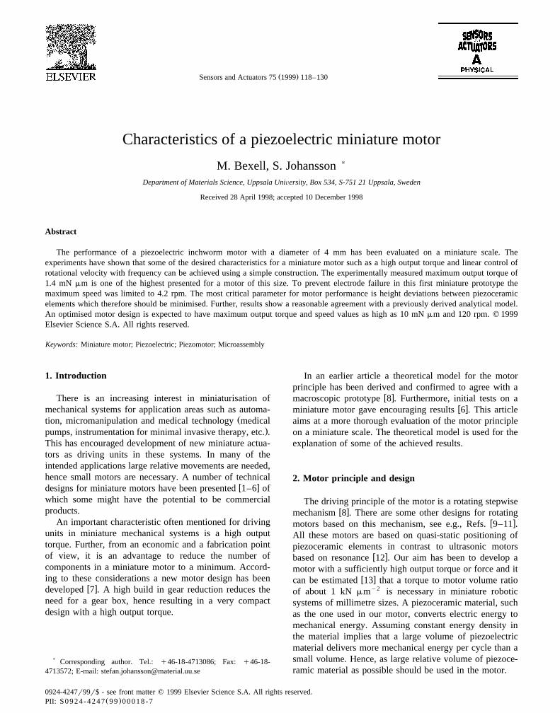
Ž .Fig. 1. Working principle left hand side of a piezoceramic element, where the two modes of deflection and extensionrcontraction are indicated. In theŽ .motor right hand side the piezoceramic elements are divided in two sets, I and II, which can be controlled separately.
To simplify the motor construction, piezoceramic ele-ments with two axial motion capacity are used. The piezo-ceramic elements are PZT bimorphs which in principle can
Žbe described as two piezoelectric layers, see Fig. 1 left.hand side , with one intermediate and two external elec-
trodes, electrically separated from each other. It is there-fore possible to activate each layer independent of theother with proper voltages on the electrodes. Two possiblemodes of motion for the piezoceramic elements are deflec-tion and extensionrcontraction. One such piezoceramicelement can therefore, by friction forces, move another
Ž .body back and forth. A motor, Fig. 1 right hand side ,consists of six piezoceramic elements that are divided in
Ž .two sets I and II . The rotor can be moved in an unlimited
range in a stepwise manner if the sets can be in alternatecontact with the rotor. In the experiments a phase differ-ence of 1808 between the two sets has been used. Threepiezoceramic elements in each set of piezoceramic ele-
Ž .ments indicated at the right hand side of Fig. 1 ensuresstability of the planar rotor.
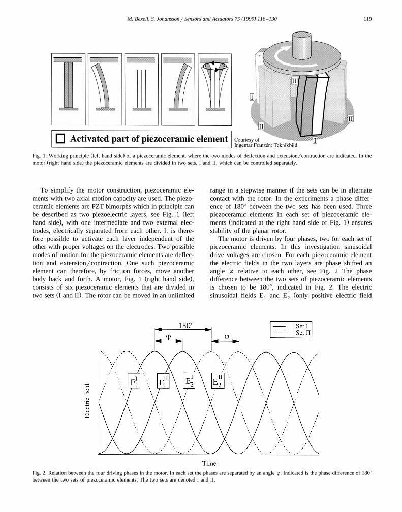
The motor is driven by four phases, two for each set ofpiezoceramic elements. In this investigation sinusoidaldrive voltages are chosen. For each piezoceramic elementthe electric fields in the two layers are phase shifted anangle w relative to each other, see Fig. 2 The phasedifference between the two sets of piezoceramic elementsis chosen to be 1808, indicated in Fig. 2. The electric
Žsinusoidal fields E and E only positive electric field1 2
Fig. 2. Relation between the four driving phases in the motor. In each set the phases are separated by an angle w. Indicated is the phase difference of 1808
between the two sets of piezoceramic elements. The two sets are denoted I and II.

( )M. Bexell, S. JohanssonrSensors and Actuators 75 1999 118–130120
values are allowed since depoling of the ceramic material.otherwise will occur of layers 1 and 2 in one piezoce-
ramic element can be written as
E Em mE s q sin v x 1aŽ . Ž .1 2 2
E Em mE s q sin v xqw 1bŽ . Ž .2 2 2
where E is the maximum electric field amplitude in onem
layer, v is the angular frequency for the applied electricw xfields and x is time. From Ref. 8 , the deflection, w, and
the extensionrcontraction displacement, e, of the piezoce-Ž .ramic element tip without external load due to electric
fields E and E in the two layers are given by1 2
3L2d E31 mws sin v xqw ysin v x 2aŽ . Ž . Ž .Ž .
4 t 2
Ld E31 mes 2qsin v xqw ysin v x 2bŽ . Ž . Ž .Ž .
2 2
where L, d , and t are the length, the piezoelectric31
coefficient and the thickness for the piezoceramic element,respectively.
Ž . Ž .Eqs. 2a and 2b can be identified as an ellipse whichcan written in the following general form
wsw qa cos v x 3aŽ . Ž .0
ese qb sin v x 3bŽ . Ž .0
Ž . Ž . Ž . Ž .By comparing Eqs. 2a , 2b , 3a and 3b the coeffi-cients w , e , a and b can be expressed as0 0
w s0 4aŽ .0
Ld E31 me s 4bŽ .0 2
3L2d E31 mas sin wr2 4cŽ . Ž .
4 t
Ld E31 mbs cos wr2 4dŽ . Ž .
2
Ž . Ž . Ž . Ž . Ž . Ž .Eqs. 3a , 3b , 4a , 4b , 4c and 4d describes that dueto a phase shift w between the two sinusoidal electricfields in an piezoceramic element, the tip will move alongan elliptical trajectory.
3. Motor fabrication
The stator of the miniature motor consists of a siliconŽ .Si substrate with an electrode pattern and six piezoce-ramic elements. Each piezoceramic element have the di-
Ž .mensions 2=1=0.9 mm L=w= t, see Fig. 3 andŽ .consists of alternating layers of active material PZT and
silverrpalladium electrodes. The electrode distance is aboutŽ .56 mm 14 active layers and the electrode thickness is 3
Fig. 3. Schematic drawing of a piezoceramic element.
to 4 mm. The piezoceramic elements have been made byŽ . Žcutting dice sawing a large multilayer PZT plate which.is poled into smaller piezoceramic elements, which there-
Žafter have been polished to equal dimensions accuracy of."5 mm .
The two layer electrode pattern on the Si substrate ismade by standard lithographic techniques. Deposited on abottom layer of thermal oxide is a first electrode layer of
˚2000 A aluminium by electron beam evaporation. As˚insulation between the electrode layers a 8000 A low
Ž .temperature SiO LTO is used. The via-holes in the LTO2
for electric connection between the electrode layers havebeen made by reactive ion etching. The second electrode
˚ ˚layer consists of 2000 A Ni on top of 500 A Ti, bothdeposited by electron beam evaporation. Titanium is usedas an adhesion layer on the LTO and nickel is used as aseed layer for an approximately 5 mm-thick electroplatedtinrlead solder of eutectic composition. The electrodes inevery electrode area are connected in such a way that thepiezoceramic elements will behave like piezoelectric bi-morphs when an electric field is applied to them. Thedesign of the electrode pattern is shown in Fig. 4a. Fig. 4bshows one of six electrode areas where electrodes in onepiezoceramic element are subsequently soldered againstthe corresponding electrodes in the electrode pattern. Themaximum current the aluminium electrodes could carrybefore electrical failure occurs has been measured to 5mA.
The assembly of the stator is performed with a micropo-sitioning table and visual aid by an optical stereomicro-scope. Soldering is achieved with the use of a heating unitand handling of the piezoceramic elements by a vacuumtool, Fig. 5. The vacuum tool is fixed above the heatingunit. The stage on which the heating unit is mountedallows linear motion in the X-, Y-, and Z-direction as wellas rotation around the Z-axis. The temperature is measuredwith a thermocouple inside the heating unit, close to itsupper surface.

( )M. Bexell, S. JohanssonrSensors and Actuators 75 1999 118–130 121
Ž . Ž .Fig. 4. a The electrode pattern design and b one of the electrode areas where a piezoceramic element will subsequently be soldered. The hexagonalŽ . Ž . Ž .pattern in a is the bottom aluminium electrode layer. The arrows in b show where connections are made via-holes to the upper electrode layer.
Ž . Ž .Electrodes denoted with A are connected to one phase and B to the other phase in the piezoceramic element. Earth electrodes are those not marked inŽ . Ž . Ž .the figure every second . Marked with a cross = are the bonding pads where electric leads insulated copper wires are connected to the electrode
pattern.
The assembly procedure, indicated in Fig. 5, is carriedout in the following way: first, all six piezoceramic ele-ments are placed onto the heating unit. The whole assem-bly procedure is carried out in air and an active liquid fluxŽ .Multicore PC 29-17 is used to remove oxide, preventoxidation of the solder and promote solder wetting on theAgrPd electrodes in the piezoceramic elements duringassembling. The liquid flux is applied on the electrodepattern and the temperature is increased to 2158C. There-after, a piezoceramic element is picked up by the vacuum
Fig. 5. A sequence of the assembling procedure: shown is a partlyŽ . Ž .assembled stator clamped to the heating unit A , and the vacuum tool B
holding a piezoceramic element.
tool and the electrodes in the piezoceramic element arealigned correctly against the electrodes in the electrodepattern and placed onto the liquid solder. The remainingpiezoceramic elements are subsequently placed in the samemanner as the first element. After the assembly is carriedout the heating unit is turned off and when it has reachedambient temperature the stator is cleaned with acetone.Thereafter a cyano-acrylate underfill is incorporated in the
Fig. 6. The assembled stator of the miniature motor. The diameter andheight are 4 mm and 2 mm, respectively.
( )M. Bexell, S. JohanssonrSensors and Actuators 75 1999 118–130122
space between the piezoceramic element and the siliconplate to improve the mechanical strength of the jointbetween the piezoceramic element and the substrate. Anassembled stator with dimensions of 4 mm in diameter and2 mm in height is shown in Fig. 6. Sapphire plates areglued onto the piezoceramic elements to serve as contact
Ž .surfaces against the rotor also made of sapphire andprotect the piezoceramic elements from wear. The glue
Žused was a two-component epoxy adhesive EPO-TEC.U300 cured at 1208C for 15 min. To minimise deviation
in height between contact surfaces on the piezoceramicelements the stator was polished with the aid of a Gatandisc grinder and an extremely flat and hard polishing cloth.Electric leads consisting of insulated copper wires wereglued to the bonding pads, see Fig. 4a, with a silveradhesive.
4. Experimental
In order to compare experimental values with the theo-retical motor model, material data for the piezoceramicelement is needed. The piezoceramic element is a compos-ite consisting of alternating layers of active material andelectrode material. Therefore it is difficult to use materialsdata as the piezoelectric coefficient, d properly. Instead,31
by measuring the contraction of the element due to anelectric field, an ‘effective piezoelectric coefficient’ deff
31Ž Ž ..for the composite can be obtained Eq. 2a . For this
particular measurement one element was assembled to theSi substrate according to the procedure described above.The measurement have been made with a surface probe
Ž .microscope SPM , which in this particular measurement˚had a resolution in the order of 1 A. Simultaneously as the
SPM scanned the surface of the piezoceramic element tip,consisting of a sapphire plate, a triangular voltage, from
Žzero up to a maximum 56 V, corresponding to an electricy1 .field strength of 1 MV m and then back to zero again,
was applied to the piezoceramic element. Errors in heightinformation from the sapphire plate could be neglected inthe measurements due to the extreme flatness of the sap-
Ž .phire surface scanning range 20=20 mm . In general, thepiezoelectric d coefficient is measured at resonance with31
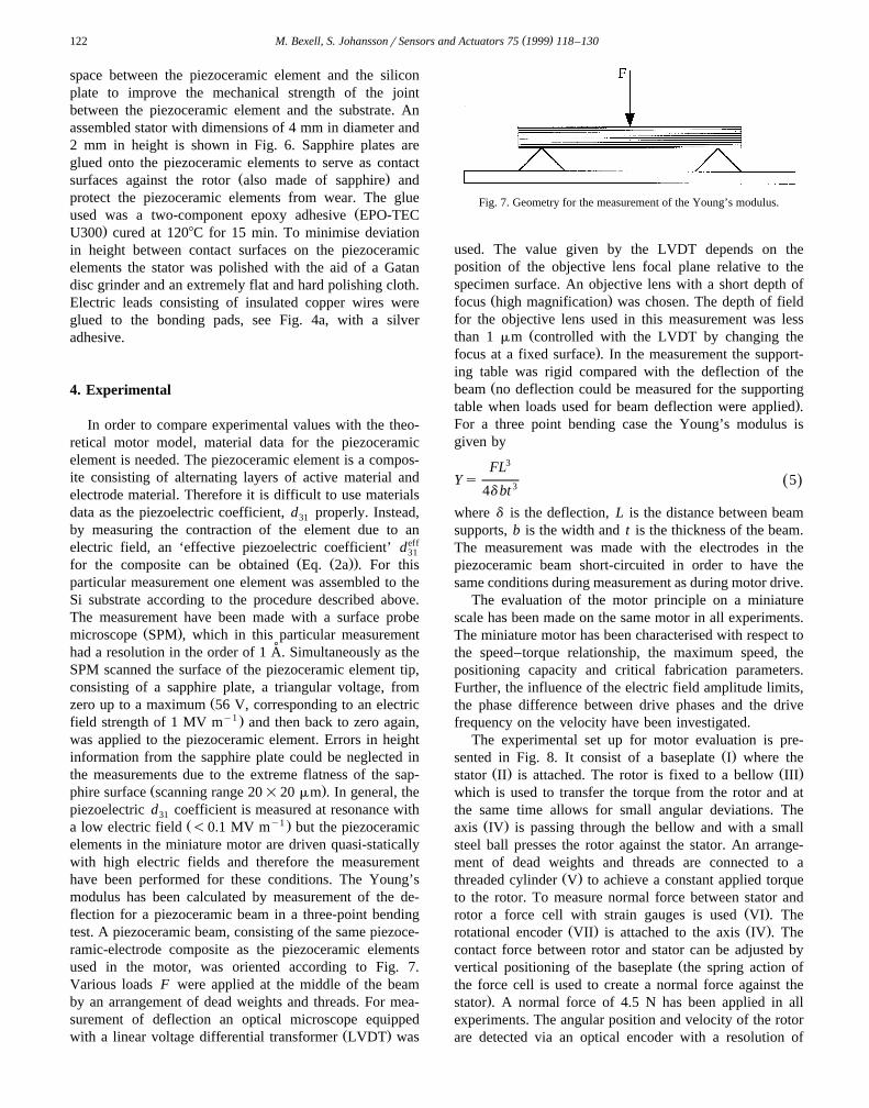
Ž y1 .a low electric field -0.1 MV m but the piezoceramicelements in the miniature motor are driven quasi-staticallywith high electric fields and therefore the measurementhave been performed for these conditions. The Young’smodulus has been calculated by measurement of the de-flection for a piezoceramic beam in a three-point bendingtest. A piezoceramic beam, consisting of the same piezoce-ramic-electrode composite as the piezoceramic elementsused in the motor, was oriented according to Fig. 7.Various loads F were applied at the middle of the beamby an arrangement of dead weights and threads. For mea-surement of deflection an optical microscope equipped
Ž .with a linear voltage differential transformer LVDT was
Fig. 7. Geometry for the measurement of the Young’s modulus.
used. The value given by the LVDT depends on theposition of the objective lens focal plane relative to thespecimen surface. An objective lens with a short depth of
Ž .focus high magnification was chosen. The depth of fieldfor the objective lens used in this measurement was less
Žthan 1 mm controlled with the LVDT by changing the.focus at a fixed surface . In the measurement the support-
ing table was rigid compared with the deflection of theŽbeam no deflection could be measured for the supporting
.table when loads used for beam deflection were applied .For a three point bending case the Young’s modulus isgiven by
FL3
Ys 5Ž .34d bt
where d is the deflection, L is the distance between beamsupports, b is the width and t is the thickness of the beam.The measurement was made with the electrodes in thepiezoceramic beam short-circuited in order to have thesame conditions during measurement as during motor drive.
The evaluation of the motor principle on a miniaturescale has been made on the same motor in all experiments.The miniature motor has been characterised with respect tothe speed–torque relationship, the maximum speed, thepositioning capacity and critical fabrication parameters.Further, the influence of the electric field amplitude limits,the phase difference between drive phases and the drivefrequency on the velocity have been investigated.
The experimental set up for motor evaluation is pre-Ž .sented in Fig. 8. It consist of a baseplate I where the
Ž . Ž .stator II is attached. The rotor is fixed to a bellow IIIwhich is used to transfer the torque from the rotor and atthe same time allows for small angular deviations. The
Ž .axis IV is passing through the bellow and with a smallsteel ball presses the rotor against the stator. An arrange-ment of dead weights and threads are connected to a
Ž .threaded cylinder V to achieve a constant applied torqueto the rotor. To measure normal force between stator and
Ž .rotor a force cell with strain gauges is used VI . TheŽ . Ž .rotational encoder VII is attached to the axis IV . The
contact force between rotor and stator can be adjusted byŽvertical positioning of the baseplate the spring action of
the force cell is used to create a normal force against the.stator . A normal force of 4.5 N has been applied in all
experiments. The angular position and velocity of the rotorare detected via an optical encoder with a resolution of

( )M. Bexell, S. JohanssonrSensors and Actuators 75 1999 118–130 123
Fig. 8. The experimental set-up for evaluation of the motor principle on aŽ . Ž .miniature scale. It consists of a baseplate I where the stator II is
Ž . Ž .attached. The rotor is fixed to a bellow III . The axis IV is passingthrough the bellow and presses the rotor against the stator. To achieve a
Žconstant torque an arrangement of dead weights and threads not seen in. Ž .the figure are connected to a threaded cylinder V . Normal force
Ž .between stator and rotor is measured with a force cell VI . Position isŽ . Ž .measured with a rotational encoder VII attached to the axis IV .
720,000 countsrturn. Measurements of rotor position withtime are made with a computer program synchronised bytrigger pulses. The phase, amplitude and frequency for thesinusoidal voltages used for motor drive are controlled bya programmable four channel digital–analogue voltage
Žsource connected to a medium-power voltage amplifier 6.W . In the experiments the rotational velocity was ex-
pressed as radsy1 and calculated by dividing the angle forŽ .one turn 2p radians with the measured time for one turn.
For all measurements at least ten turns were measured inorder to investigate fluctuations in speed. The presentedrotational velocities are the calculated average rotationalvelocities.
Deviations in piezoceramic element height relative to anideal planar rotor are important parameters to measure.The evaluation was made by observing the movement ofinterference fringes between a transparent planar glassplate and the sapphire plates on the piezoceramic elements.The glass plate had a flatness better than 20 nm, according
Žto measurements with a alpha-step 200 Tencor Instru-
.ments surface profilometer. The spacing between a flatglass plate in contact with the convex surface of thesapphire plates on the piezoceramic elements results ininterference fringes with proper illumination. When rela-tive motion between the glass plate and a sapphire plateoccurs the fringes change. The interference fringes wereobserved with aid of an optical stereomicroscope. A volt-age was applied to one set of piezoceramic elements withthe other set non-activated. The activated set of piezoce-ramic elements moves downwards and for the elementsthat are not in contact with the glass plate the interferencefringes change. At a certain voltage level no piezoceramicelements in the activated set will be in contact with theglass plate. In this situation the interference fringes do notchange on any of the non-activated piezoceramic elements.
Ž Ž ..This voltage level was used to calculate Eq. 2b therelative displacement necessary to reach a contact situationwhere only piezoceramic elements from one set is incontact with the rotor. The same measurement was alsomade with the other set activated.
5. Results and discussion
The materials parameters needed in the motor model arethe Young’s modulus and the piezoelectric coefficient d .31
Since the piezoceramic elements are composites with non-Ž .activated material electrode and cover layers an effective
deff has been used in the model. The contraction of the31
particular piezoceramic element was measured to 0.72 mmat an applied voltage of 56 V. This would correspond to aneffective deff of y0.36 nm Vy1. The accuracy of this31
measurement was about "5%. In comparison the d31
coefficient of commercially available material has a stan-w xdard deviation of "5% 14 . A standard measurement of
the PZT material used would yield a value of abouty0.15–y0.25 nmVy1. The main reason that the effectivedeff is higher, even though the piezoceramic element in-31
cludes non-activated material, is that the measurements aremade at a high electric field. The electric field values arethe same as those used for the motor drive. The Young’s
Ž .modulus short-circuit conditions for the particular piezo-ceramic-electrode material composite used in the piezoce-
Ž Ž ..ramic elements was calculated to 56"3 GPa Eq. 5 .By inserting the effective piezoelectric coefficient and
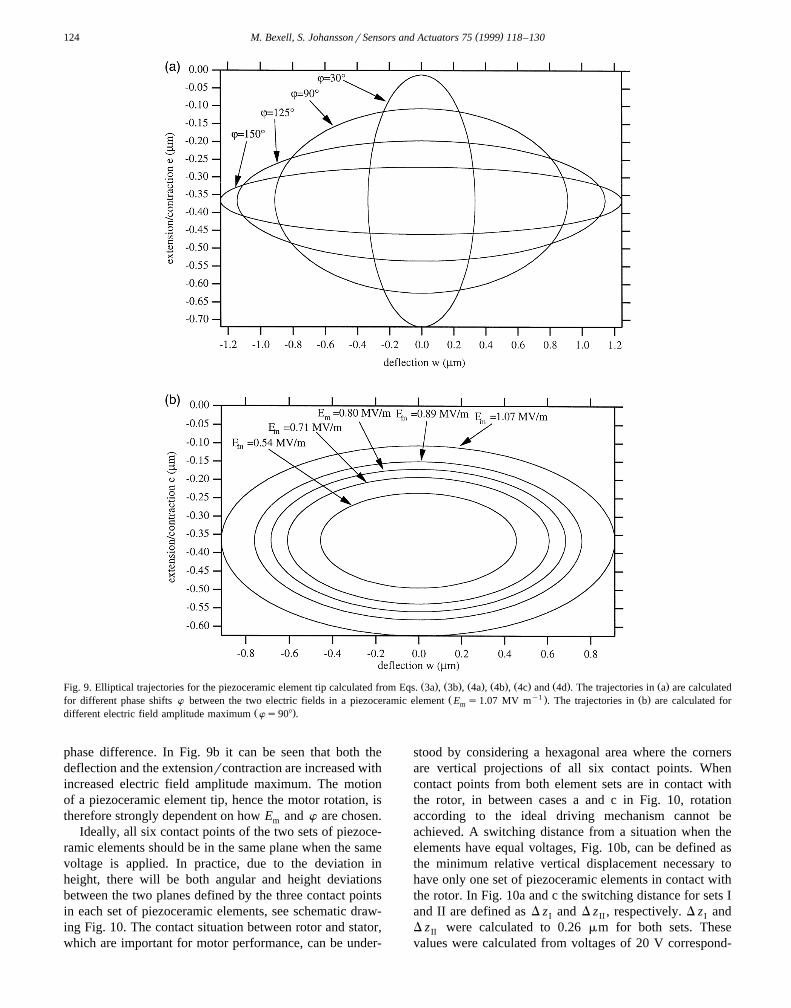
Ž .the dimensions given above for the piezoceramic elementŽ . Ž . Ž . Ž .in Eqs. 4a , 4b , 4c and 4d the appearance for differ-
ent theoretically calculated elliptical trajectories for thepiezoceramic element tip can be shown, Fig. 9a and b. InFig. 9a the phase difference w is varied with a givenelectric field amplitude maximum. In Fig. 9b trajectories
Žfor different electric field amplitude maximum E phasem.difference of 908 is shown. As seen in Fig. 9a the
deflection of the piezoceramic element is increased, whilethe extensionrcontraction is decreased, with increased
( )M. Bexell, S. JohanssonrSensors and Actuators 75 1999 118–130124
Ž . Ž . Ž . Ž . Ž . Ž . Ž .Fig. 9. Elliptical trajectories for the piezoceramic element tip calculated from Eqs. 3a , 3b , 4a , 4b , 4c and 4d . The trajectories in a are calculatedŽ y1 . Ž .for different phase shifts w between the two electric fields in a piezoceramic element E s1.07 MV m . The trajectories in b are calculated form
Ž .different electric field amplitude maximum ws908 .
phase difference. In Fig. 9b it can be seen that both thedeflection and the extensionrcontraction are increased withincreased electric field amplitude maximum. The motionof a piezoceramic element tip, hence the motor rotation, istherefore strongly dependent on how E and w are chosen.m
Ideally, all six contact points of the two sets of piezoce-ramic elements should be in the same plane when the samevoltage is applied. In practice, due to the deviation inheight, there will be both angular and height deviationsbetween the two planes defined by the three contact pointsin each set of piezoceramic elements, see schematic draw-ing Fig. 10. The contact situation between rotor and stator,which are important for motor performance, can be under-
stood by considering a hexagonal area where the cornersare vertical projections of all six contact points. Whencontact points from both element sets are in contact withthe rotor, in between cases a and c in Fig. 10, rotationaccording to the ideal driving mechanism cannot beachieved. A switching distance from a situation when theelements have equal voltages, Fig. 10b, can be defined asthe minimum relative vertical displacement necessary tohave only one set of piezoceramic elements in contact withthe rotor. In Fig. 10a and c the switching distance for sets Iand II are defined as D z and D z , respectively. D z andI II I
D z were calculated to 0.26 mm for both sets. TheseII
values were calculated from voltages of 20 V correspond-

( )M. Bexell, S. JohanssonrSensors and Actuators 75 1999 118–130 125
Fig. 10. Schematic drawing illustrating height and angular deviations between the two planes defined by the three contact points in each set ofpiezoceramic elements. The densely striped plane is defined by the contact points in set I and the sparsely striped plane is defined by contact points in set
Ž . Ž . Ž .II. The switching between the two sets of piezoceramic elements are illustrated by a , b and c . If the same voltage is applied to both sets ofŽ . Ž .piezoceramic elements, b , in general the planes are displaced a distance D z at the centre position. From the situation in b a vertical displacement D z ,0 I
Ž . Žof plane I relative to plane II according to a is necessary to have only contact points in set I in contact with the rotor the starting position for plane I is. Ž .illustrated with a hatched contour line in a . Analogously, a relative vertical displacement D z , c is needed to have only set II in contact with the rotor.II
ing to electric fields of 0.36 MV mmy1. In this particularcase both D z and D z were equal but in general theseI II
values may differ from each other. The switching distancecan be assumed to influence motor characteristics which isfurther investigated below.
The average rotational velocity for different electricfield amplitude maximum E was measured, Fig. 11. Them
drive frequency was 166 Hz and the phase differencebetween the two electric fields was 908. As expected therotational velocity increases with electric field amplitudemaximum. As seen in Fig. 11 the rotor does not turn whenthe electric field amplitude maximum value is below a
Ž y1 .certain level 0.50 MV mm . For this level, with aid ofŽ .Eq. 4d , the maximum vertical displacement in the ellipti-
cal trajectory was calculated to 0.25 mm. This is in accor-dance with the measured minimum vertical displacementneeded for switching between the two sets of piezoceramicelements. A variation of the mean rotational velocityŽ .calculated for ten full turns in the order of 10% was
Žobserved in all measurements indicated in the figures as.error bars . The variation in mean rotational velocity is
probably due to effects from instabilities during switchingbetween the driving sets, variations in friction duringgripping for the driving elements and small dust particlesentering the space between rotor and the piezoceramicelements. A limited change of rotational velocity can beachieved, about a factor of 5, by adjusting the appliedvoltage. This could for instance be used for minor adjust-ments of rotational velocity. For this particular motor adrive voltage less than 28 V cannot turn the rotor. Ingeneral, as low drive voltages as possible is often desiredand one way of accomplishing this is to reduce heightdeviations between piezoceramic elements.
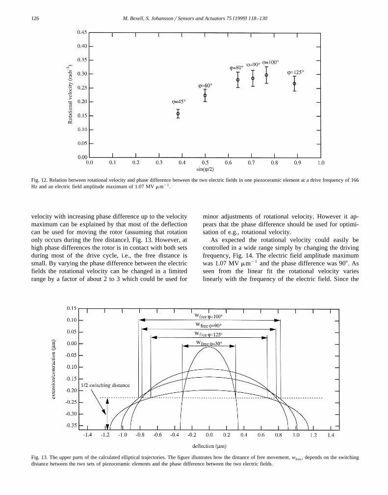
The influence of phase difference, w, on average rota-tional velocity was investigated, Fig. 12. The rotational
Ž .velocity is plotted as a function of sin wr2 for a drivefrequency of 166 Hz and electric field amplitude maxi-mum of 1.07 MV mmy1. An ideal motor, i.e., in particularwithout height deviations between piezoceramic elements,
should have a linear relation between rotational velocityŽ . Ž Ž . Ž . Ž . Ž . Ž . Ž ..and sin wr2 Eqs. 3a , 3b , 4a , 4b , 4c and 4d .
The deviation between the expected linear behaviour andthe experimentally derived values can be explained withhelp of the measured minimum vertical displacement nec-essary for switching between the two sets of active ele-ments. The rotor cannot easily be turned by one set ofpiezoceramic elements if the other set is still in contactwith the rotor, i.e., within the switching distance. For thisparticular motor where both D z and D z were equalI II
switching between the two sets can be regarded to occursymmetrically around an imagined centre line of the ellip-tical trajectories, see Fig. 13. In Fig. 13 only the upper partof the elliptical trajectory is shown and therefore only halfthe switching distance is indicated with a dashed line. Thevertical displacement needed for switching between thetwo sets is reached at different positions in the ellipticaltrajectories for the piezoceramic elements depending onthe phase difference. This dependence is illustrated in Fig.13 for some different angles w. The free distance w isfree
the distance where only one set is in contact with the rotor.It can be seen in Fig. 12 that a phase of about 1008 givesthe maximum rotational velocity. The increase in rotational
Fig. 11. Relation between rotational velocity and electric field amplitudeŽ .maximum at a fixed drive frequency 166 Hz and phase difference
Ž .between the two electric fields 908 .
( )M. Bexell, S. JohanssonrSensors and Actuators 75 1999 118–130126
Fig. 12. Relation between rotational velocity and phase difference between the two electric fields in one piezoceramic element at a drive frequency of 166Hz and an electric field amplitude maximum of 1.07 MV mmy1.
velocity with increasing phase difference up to the velocitymaximum can be explained by that most of the deflection
Žcan be used for moving the rotor assuming that rotation.only occurs during the free distance , Fig. 13. However, at
high phase differences the rotor is in contact with both setsduring most of the drive cycle, i.e., the free distance issmall. By varying the phase difference between the electricfields the rotational velocity can be changed in a limitedrange by a factor of about 2 to 3 which could be used for
minor adjustments of rotational velocity. However it ap-pears that the phase difference should be used for optimi-sation of e.g., rotational velocity.
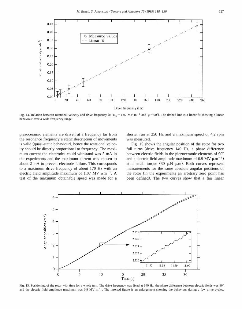
As expected the rotational velocity could easily becontrolled in a wide range simply by changing the drivingfrequency, Fig. 14. The electric field amplitude maximumwas 1.07 MV mmy1 and the phase difference was 908. Asseen from the linear fit the rotational velocity varieslinearly with the frequency of the electric field. Since the
Fig. 13. The upper parts of the calculated elliptical trajectories. The figure illustrates how the distance of free movement, w , depends on the switchingfree
distance between the two sets of piezoceramic elements and the phase difference between the two electric fields.
( )M. Bexell, S. JohanssonrSensors and Actuators 75 1999 118–130 127
Ž y1 .Fig. 14. Relation between rotational velocity and drive frequency at E s1.07 MV m and ws908 . The dashed line is a linear fit showing a linearm
behaviour over a wide frequency range.
piezoceramic elements are driven at a frequency far fromthe resonance frequency a static description of movements
Ž .is valid quasi-static behaviour , hence the rotational veloc-ity should be directly proportional to frequency. The maxi-mum current the electrodes could withstand was 5 mA inthe experiments and the maximum current was chosen toabout 2 mA to prevent electrode failure. This correspondsto a maximum drive frequency of about 170 Hz with anelectric field amplitude maximum of 1.07 MV mmy1. Atest of the maximum obtainable speed was made for a
shorter run at 250 Hz and a maximum speed of 4.2 rpmwas measured.
Fig. 15 shows the angular position of the rotor for twoŽfull turns drive frequency 140 Hz, a phase difference
between electric fields in the piezoceramic elements of 908y1 .and a electric field amplitude maximum of 0.9 MV mm
Ž .at a small torque 30 mN mm . Both curves representmeasurements for the same absolute angular positions of
Žthe rotor in the experiments an arbitrary zero point has.been defined . The two curves show that a fair linear
Fig. 15. Positioning of the rotor with time for a whole turn. The drive frequency was fixed at 140 Hz, the phase difference between electric fields was 908
and the electric field amplitude maximum was 0.9 MV my1. The inserted figure is an enlargement showing the behaviour during a few drive cycles.

( )M. Bexell, S. JohanssonrSensors and Actuators 75 1999 118–130128
Žbehaviour of rotation angle with time as would ideally be.expected can be achieved. It was found that the rotor
position does not deviate with more than about a fewpercent when a comparison between the two curves wasmade. It was difficult to align the experimental set-upideally and therefore rotational velocity variations havebeen expected. The similarity in curve shape of the two
Ždifferent curves in Fig. 15 the deviation from an ideal.linear behaviour is similar is in accordance with this. The
problems with alignment can be reduced by a completeredesign of the experimental set up which is a futureproject. The differences between the two curves in Fig. 15is probably due to effects from instabilities during switch-ing from one set to the other driving sets, variations infriction during gripping for the driving elements and smalldust particles entering the space between rotor and stator.The discontinuous behaviour seen in the insert of Fig. 15could be explained by the variations of the lateral velocity
Žin the elliptical trajectory due to the sinusoidal drive.cycles and instabilities during switching between the two
sets. Also, resonance in the experimental set-up couldaffect the measurement.
Experimental and theoretical torque vs. rotational veloc-ity data are presented in Fig. 16. The drive frequency was170 Hz, the phase difference between the electric field was908 and the electric field amplitude maximum was 1.07MV mmy1. The theoretical curve was calculated using
w xexperimental data inserted in the earlier derived model 8which is based on small, one dimensional, bending approx-
Ž .imations. From Eq. 4c the maximum theoretical deflec-tion for the piezoceramic element tip can be calculated to
Ž . Ž1.82 mm ws908 . By knowing the drive frequency 170. Ž .Hz and length for one turn f10 mm the maximum
rotational speed could be calculated to 0.39 radsy1. Above,
the Young’s modulus has been measured to 56 GPa. Themodel gives a linear decreasing torque with increasingrotational velocity, since the movement of the rotor shouldbe directly proportional to the movement of the piezoce-ramic elements tips. When a force is applied to the ele-ments elastic deflections opposing the electromechanicaldeflection will occur. Since the elastic deflection is linearlyproportional to the applied force, the delivered torqueshould be proportional to the step length and therefore alsoto the rotational velocity at a fixed frequency. Deviationsbetween the measured and the theoretical maximum rota-tional velocity values in Fig. 16 are expected due to heightdifferences between piezoceramic elements, see Fig. 13.As a consequence, the measured torque values should belower compared with the theoretical for a given rotationalvelocity. The deviations in slope between the theoreticaland measured curves in Fig. 16 are considered to a largeextent reflect the behaviour of the experimental set-up,
Ž .since during certain parts of a turn typical a half turn therotational velocity was close to the expected at a givenrotational velocity. The holding torque value, i.e., when nopower is applied to the motor, of 1.7 mN mm is a little bithigher than the maximum torque of 1.4 mN mm obtainedduring operation. There might be several reasons for thissuch as a higher coefficient of friction at zero speed and ahigher normal force between piezoceramic elements androtor when no power is applied. In some certain rotorpositions the set might have a poor contact with the rotor.An interesting aspect of a high holding torque is that therotor can be locked in any desired position which may beof importance in e.g., robotic applications. From the hold-ing torque the coefficient of friction was calculated to 0.25Žnormal force 4.5 N, holding torque 1.7 mN m and a radius
.of 1.5 mm The analytical model is only valid as long as
Fig. 16. The relation between torque and rotational velocity for the miniature motor with a fixed drive frequency of 170 Hz, a phase difference betweenelectric fields of 908 and an electric field amplitude maximum of 1.07 MV my1.

( )M. Bexell, S. JohanssonrSensors and Actuators 75 1999 118–130 129
there is no gliding between the piezoceramic elements andthe rotor which depends both on the coefficient of frictionbetween piezoceramic elements and rotor and the appliednormal force. The case of a friction limited output torqueis indicated as a plateau in Fig. 16 with the dashed line.Therefore, there is a possibility of having a built-in over-load protection in the motor if proper combinations ofnormal force and coefficient of friction is chosen. This canbe of interest in applications where mechanical failure of awhole system can otherwise occur. By using other materialcombinations for the stator–rotor contact, see e.g., Ref.w x12 , it would be possible to achieve a higher coefficient offriction and hence increase the maximum output torque.The above mentioned estimated torque to motor volumeratio of about 1 kN mmy2 necessary for miniature actuatorsystem applications can be compared with the experimen-tally derived value of about 40 kN mmy2 . This value,about 40 times higher than the desired, confirms that themotor principle is well suited as a drive unit in applica-tions where a high output torque in a limited volume ofspace is required.
The reasonable agreement between the experimentalŽ .results and the analytical model for maximum values
validates further use in estimations of the performance forvarious motor designs. A miniature motor of the same sizeas the one evaluated here with a more optimised design,
Ži.e., a higher constant of friction e.g., 0.5 which is a factor.two higher than for the motor evaluated and an electrode
pattern suitable for higher drive frequencies, could reach atorque and a rotational speed as high as 10 mN mm and120 rpm.
The maximum output torque of 1.4 mN mm is one ofthe highest presented for a motor of this size. Using the
w xtheoretical model given in Ref. 8 a comparison with othermotor designs can be made. In comparison with highperformance motors, e.g., miniature electromagnetic mo-
w x w xtors 1 and piezoelectric ultrasonic motors 2 , our presentprototype motor has a maximum torque value more than 5times higher.
6. Conclusions
Characteristics for a piezoelectric miniature motor havebeen experimentally investigated. A previously derivedanalytical model has been used to explain some of theresults for the 4 mm in diameter miniature motor and areasonable agreement has been found.
Performance and characteristics for the motor can besummarised as follows:Ø The experimentally derived maximum output torque of
1.4 mN mm is one of the highest presented for a motorof this size.
Ø The maximum rotational velocity was limited to 4.2rpm in order to prevent electrode failure.
Ø The most effective way to vary the rotational velocity isby changing the frequency of the driving field.
Ø In order to optimise the motor characteristics deviationsin height between the two sets of piezoceramic ele-ments should be minimised.
Acknowledgements
Ulf Helin, Jonas Tiren, and Bengt Lindekvist, ABB´HAFO have given us valuable help with the electroplatingof the electrode pattern. The Industrial Microelectronics
Ž .Center IMC assisted in the fabrication of the electrodepattern. The Swedish National Board for Industrial and
Ž .Technical Development NUTEK and the Swedish Re-Ž .search Council for Engineering Science TFR have sup-
ported the project financially.
References
w x1 H. Lehr, S. Abel, J. Dopper, W. Ehrfeld, B. Hagermann, K.-P.¨Kampfer, F. Michel, Ch. Thuringen, Microactuators as driving units¨ ¨for microrobotic systems, Proc. SPIE, Microrobotics: Components
Ž .and Applications, Vol. 2906, Boston, Massachusetts 1996 202–210.w x2 W. Vishnewsky, R. Gloß, Piezoelectric rotary motors, Proc. Actua-¨
tor 96, Bremen, Germany, 1996, pp. 245–248.w x3 T. Itoh, Micro-machine technology tackles challenge of motor
Ž . Ž .miniaturisation, Journal of Electronic Engineering 30 313 199358–62.
w x4 K. Nakamura, H. Ogura, S. Maeda, U. Sangawa, S. Aoki, T. Sato,Evaluation of the microwobble motor fabricated by concentric build-up process, Proc. MEMS, 1995, pp. 374–379.
w x5 T. Sato, Step from 2- to 3-D process breaks ground for microfabri-Ž .cated wobble motors, Journal of Electronic Engineering, 31 332
Ž .1994 67–70, 80.w x6 M. Bexell, S. Johansson, A high torque miniature inchworm motor,
Ž .Proc. Transducers ’95, Late News Contributions 1995 69–70.w x7 S. Johansson, Piezomotor, Swedish Patent Appl. No. S 9300305-1,
1993.˚w x8 M. Bexell, A.-L. Tiensuu, J.-A. Schweitz, J. Soderberg, S. Johans-¨
son, Characterisation of an inchworm prototype motor, Sensors andŽ .Actuators A 43 1994 322–329.
w x9 J.G. Smits, Design considerations of a piezoelectric-on-silicon mi-Ž .crorobot, Sensors and Actuators A 35 1992 129–135.
w x10 J.G. Smits, Integrated micromechanical piezoelectric motor, USPatent No. 5049775, 1991.
w x11 K. Mori, Piezoelectric Rotary Actuator, US Patent No. 4468583,1984.
w x12 S. Uhea, Y. Tomikawa, Ultrasonic motors—theory and applications,Oxford Univ. Press, 1993.
w x13 S. Johansson, One approach towards the fabrication of a microrobotŽ .system, Materials Science and Engineering C 2 1995 141–149.
w x14 Ferroperm ArS Denmark, product catalogue, 1995.
Mats Bexell received his MSc degree in Materials Physics from UppsalaUniversity in 1992. The same year he joined the Division of MaterialsScience, Uppsala University. His work is mainly focused towards piezo-ceramic materials and miniaturisation of piezoceramic actuators intendedfor use in microrobotics. In 1998 he received his DrSc degree inMaterials Science at Uppsala University.

( )M. Bexell, S. JohanssonrSensors and Actuators 75 1999 118–130130
Stefan Johansson, born in Avesta, Sweden in 1960. Received his MScdegree in Engineering Physics, 1982 from Uppsala University. In 1983 hejoined the Division of Materials Science, Uppsala University where hewas concerned with development of methods for evaluation of microme-chanical properties of silicon. In 1988 he received his DrSc degree inmaterials science at Uppsala University. Since 1988 he has been workingwith different materials science aspects of micromechanics, and in partic-ular with development of processing and design of microrobotics compo-nents. He is holding a senior research position within the MicromechanicsProgramme at Uppsala University.