design of vibration-based miniature generator r3 0812rrs2is.org/issues/v3/n3/papers/paper14.pdf ·...
TRANSCRIPT
DESIGN OF VIBRATION-BASED MINIATURE GENERATOR USING PIEZOELECTRIC BENDER
Wei Li 1, Tzong-Shi Liu 1,*, Heng-I Lin 2, and Yi-Jeng Tsai 3 1 Department of Mechanical Engineering
National Chiao Tung University
Hsinchu 30010, Taiwan 2 Liung Feng Industrial Co., Taipei, Taiwan
3 Mechanical and Systems Research Laboratories,
Industrial Technology Research Institute, Hsinchu 31040, Taiwan
E-mail: [email protected]
Abstract- For the use of green energy and ubiquitous computing, this study investigates miniature
electric generators that are constructed with piezoelectric benders. Electric power is generated by
vibratory deformation of piezoelectric benders. Three different designs of piezoelectric generators
are created and compared in this study by using mechanics analysis. The result shows that the
cantilever design yields more power than symmetric and airfoil designs. Experimental results show
that generated voltage rises with not only attached point masses, but also the swing frequency of a
swing arm, to which the proposed piezoelectric generator is attached. In addition, At 6.5 Hz swing
frequency, the maximum power 0.3µW is generated.
Index terms: Miniature Generator, Piezoelectric Bender, Energy Harvesting.
550
INTERNATIONAL JOURNAL ON SMART SENSING AND INTELLIGENT SYSTEMS, VOL. 3, NO. 3, SEPTEMBER 2010
I. INTRODUCTION
In recent years, several kinds of energy-harvesting designs have been proposed for green
energy sources. These designs include acoustic energy collection, electromagnetic and
electrostatic power transducers, vibration of piezoelectric materials, etc.
a. Acoustic energy
Concerning the acoustic energy, or say, sound energy transducers, the electric power is
produced by coil vibration in a magnetic field, where the vibration is induced by the variation
of the sound pressure. According to Roundy et al. [1], the acoustic energy per unit volume is
very small, about 0.003µW per cubic centimeter at 75dB and 0.96µW per cubic centimeter at
100dB. Therefore, the energy is too small to be utilized for commercial power generation.
b. Electromagnetic and electrostatic transducers
Williams and Yates [2] pointed out that mechanical energy can be used to generate electric
power by a mass-spring-damper system. Mechanical energy due to vibration can be
transformed to electric power by any of three kinds of transduction mechanisms including
piezoelectric, electromagnetic, and electrostatic devices. And when the mechanical system
oscillates at a resonant frequency, there exists the maximum power transformation. Therefore,
for performance of the miniature generator, it is important to design a device with resonant
frequency coincident with frequencies which human activities result in. For those kinds of
miniature electromagnetic or electrostatic generators, the resonant frequency is much higher
than that human-being can produce, so we focus on the piezoelectric generator in this paper.
A small generator constructed with a high speed permanent magnet generator driven by
micro-turbine was used in smart grid energy systems [3]. However, it is not suitable for the
environment of vibration.
c. Vibration of piezoelectric bender
Piezoelectric materials exhibit properties of the electromechanical interaction between the
mechanical and electrical states. They can serve as actuators, like [4], due to an inverse
piezoelectric effect or as sensors due to a direct piezoelectric effect. The sensors can be made
in bulk form depicted in [5] or in the form of thin film to sense cracks [6]. If a lot of electrical
charges are generated, electric power may be available. To obtain larger energy density,
electric power can be generated by the strain change of a piezoelectric bender. The strain
551
Wei Li, Tzong-Shi Liu, Heng-I Lin, and Yi-Jeng Tsai, DESIGN OF VIBRATION-BASED MINIATURE GENERATOR USING PIEZOELECTRIC BENDER
change is caused by deformation of the piezoelectric bender. Some kinematic conditions, such
as vibration or deformation, will change the strain of the piezoelectric bender and hence
generate the electric power. As mentioned in [7] and [8], the piezoelectric material can be
used in sport shoes. When the compression of the piezoelectric material in the shoes happens,
electric power is generated. A wearable embedded system for wirelessly delimiting a
hazardous area during emergency was used [9] to alert rescue operators for safety. The power
source for this system is an issue. Therefore, Roundy and Wright proposed a power
generation method by employing vibration of piezoelectric benders [10].
d. Thermoelectric power
Another way to generate power is by the thermoelectric effect. The difference among
temperatures makes the thermoelectric device to generate the electric power. It is proposed
that power extracted from the human tissue warmth is supplied to a wireless neural recording
system implanted in human body [11]. However, it is not suitable for the environment of
vibration.
e. Amplify, rectify and charge
To use the power generated by the miniature generator, amplify and rectify circuits are needed
because the electric current generated is alternating and tiny. Another issue is how to save the
electric power, and optimize the efficiency of power transformation from piezoelectric
material to an energy storage device, such as rechargeable battery or capacitor. Koutroulis et
al. [12] proposed a method for electric energy storage, called step-down converter. Ottman et
al. [13, 14] used a full-bridge circuit to rectify the alternating current and store the electric
energy. Makihara et al. [15] replaced two diodes in the full-bridge circuit mentioned in [13,
14] by two switches to save the voltage drop by diodes for more energy storage. Sodando et al.
[16, 17] used a step-down converter to charge a rechargeable battery and a capacitor directly.
II. ANALYTICAL MODEL
This paper presents three new designs of the piezoelectric generator. To study the electric
power generation, their dynamic models will be analyzed first. Among three designs of the
piezoelectric generator, the one that yields the maximum strain will be further investigated in
this work. The three designs are depicted in figure 1: (1) cantilever type: a piezoelectric
bender is fixed at one end and a point mass M is attached to the other end. It is a model
552
INTERNATIONAL JOURNAL ON SMART SENSING AND INTELLIGENT SYSTEMS, VOL. 3, NO. 3, SEPTEMBER 2010
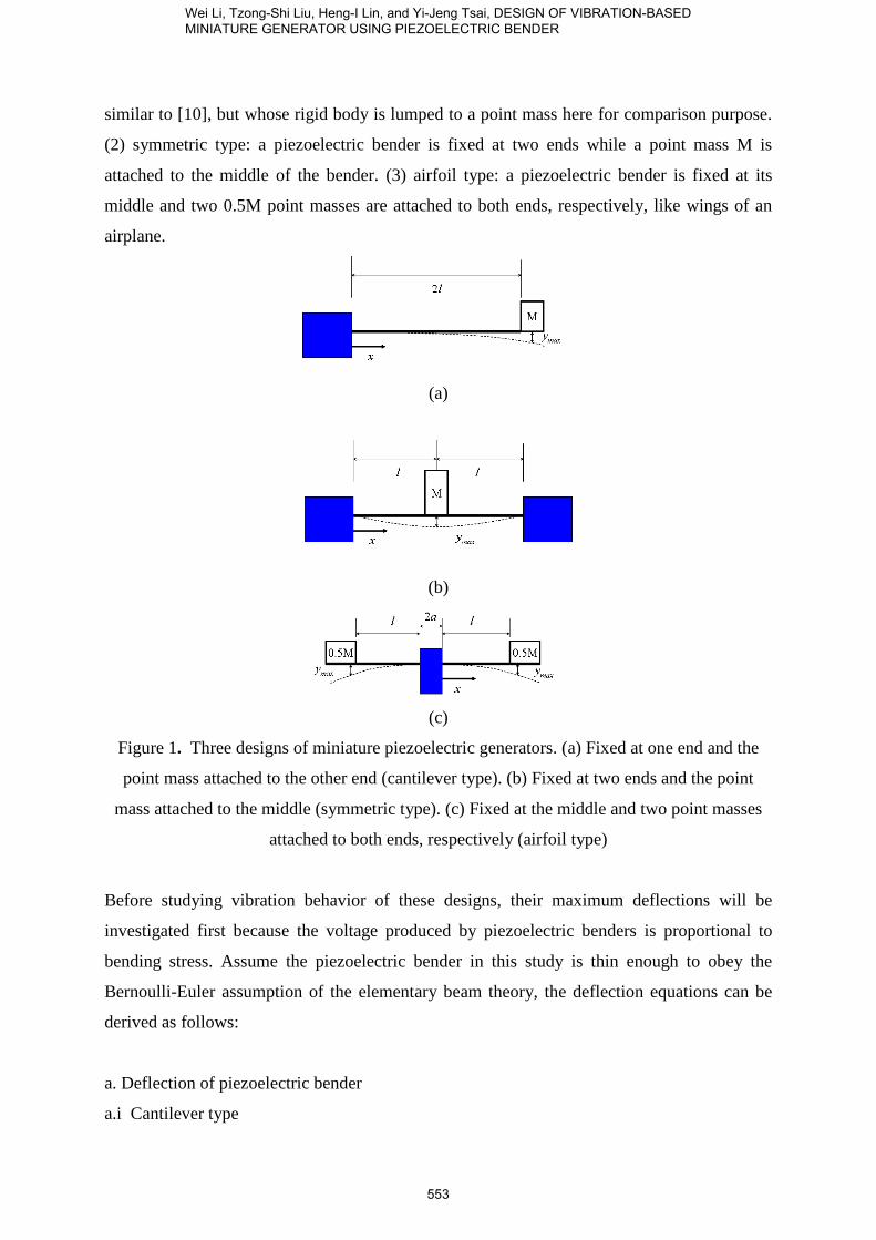
similar to [10], but whose rigid body is lumped to a point mass here for comparison purpose.
(2) symmetric type: a piezoelectric bender is fixed at two ends while a point mass M is
attached to the middle of the bender. (3) airfoil type: a piezoelectric bender is fixed at its
middle and two 0.5M point masses are attached to both ends, respectively, like wings of an
airplane.
(a)
(b)
(c)
Figure 1. Three designs of miniature piezoelectric generators. (a) Fixed at one end and the
point mass attached to the other end (cantilever type). (b) Fixed at two ends and the point
mass attached to the middle (symmetric type). (c) Fixed at the middle and two point masses
attached to both ends, respectively (airfoil type)
Before studying vibration behavior of these designs, their maximum deflections will be
investigated first because the voltage produced by piezoelectric benders is proportional to
bending stress. Assume the piezoelectric bender in this study is thin enough to obey the
Bernoulli-Euler assumption of the elementary beam theory, the deflection equations can be
derived as follows:
a. Deflection of piezoelectric bender
a.i Cantilever type
553
Wei Li, Tzong-Shi Liu, Heng-I Lin, and Yi-Jeng Tsai, DESIGN OF VIBRATION-BASED MINIATURE GENERATOR USING PIEZOELECTRIC BENDER
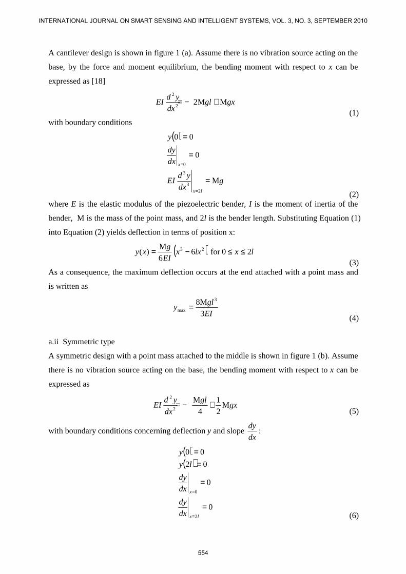
A cantilever design is shown in figure 1 (a). Assume there is no vibration source acting on the
base, by the force and moment equilibrium, the bending moment with respect to x can be
expressed as [18]
gxgldx
ydEI MM2
2
2
+−= (1)
with boundary conditions
( )
gdx
ydEI
dx
dy
y
lx
x
M
0
00
2
3
3
0
=
=
=
=
=
(2) where E is the elastic modulus of the piezoelectric bender, I is the moment of inertia of the
bender, M is the mass of the point mass, and 2l is the bender length. Substituting Equation (1)
into Equation (2) yields deflection in terms of position x:
( ) 20for 66
M)( 23 lxlxx
EI
gxy ≤≤−=
(3) As a consequence, the maximum deflection occurs at the end attached with a point mass and
is written as
EI
gly
3
M8 3
max = (4)
a.ii Symmetric type
A symmetric design with a point mass attached to the middle is shown in figure 1 (b). Assume
there is no vibration source acting on the base, the bending moment with respect to x can be
expressed as
gxgl
dx
ydEI M
2
1
4
M2
2
+−= (5)
with boundary conditions concerning deflection y and slope dx
dy:
( )( )
0
0
02
00
2
0
=
=
==
=
=
lx
x
dx
dy
dx
dy
ly
y
(6)
554
INTERNATIONAL JOURNAL ON SMART SENSING AND INTELLIGENT SYSTEMS, VOL. 3, NO. 3, SEPTEMBER 2010
where E is the elastic modulus of the piezoelectric, I is the moment or inertia of the
piezoelectric, M is the mass of the point mass, g is the acceleration of gravity, and 2l is the
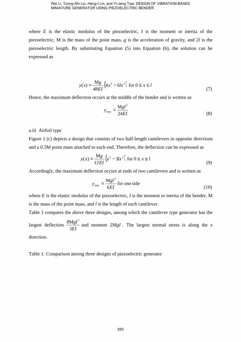
piezoelectric length. By substituting Equation (5) into Equation (6), the solution can be
expressed as
( ) 0for 6448
M)( 23 lxlxx
EI
gxy ≤≤−=
(7)
Hence, the maximum deflection occurs at the middle of the bender and is written as
EI
gly
24
M 3
max = (8)
a.iii Airfoil type
Figure 1 (c) depicts a design that consists of two half-length cantilevers in opposite directions
and a 0.5M point mass attached to each end. Therefore, the deflection can be expressed as
( ) 0for 312
M)( 23 lxlxx
EI
gxy ≤≤−=
(9)
Accordingly, the maximum deflection occurs at ends of two cantilevers and is written as
side onefor 6
M 3
max EI
gly =
(10)
where E is the elastic modulus of the piezoelectric, I is the moment or inertia of the bender, M
is the mass of the point mass, and l is the length of each cantilever.
Table 1 compares the above three designs, among which the cantilever type generator has the
largest deflection EI
gl
3
M8 3
and moment glM2 . The largest normal stress is along the x
direction.
Table 1: Comparison among three designs of piezoelectric generator
555
Wei Li, Tzong-Shi Liu, Heng-I Lin, and Yi-Jeng Tsai, DESIGN OF VIBRATION-BASED MINIATURE GENERATOR USING PIEZOELECTRIC BENDER

Types Symmetric Cantilever Airfoil (for one side)
M (x )
M (x )max
y (x )
y (x )max EI
gly
3
M8 3
max =
gxgl
dx
ydEI M
2
1
4
M2
2
+−= gxgldx
ydEI MM2
2
2
+−=
glM M4
3max = glM M2max =
2M
2M
2
2 gxgl
dx
ydEI +−=
2
Mmax
glM =
( )23 6448
M)( lxx
EI
gxy −= ( )23 6
6
M)( lxx
EI
gxy −= ( ) 3
12
M)( 23 lxx
EI
gxy −=
EI
gly
24
M 3
max=EI
gly
6
M 3
max=
In piezoelectric materials, the strain and electric field has the relationship [19]
[ ] EdSS Ts += (11)
where S is the strain vector, Ss is the spontaneous strain vector, [d]T is the transpose of
the piezoelectric constant matrix and E is the electric field vector. The piezoelectric
constant matrix is defined as
[ ]
=000
00000
00000
333231
24
15
ddd
d
d
d
(12)
where subscript 1 denotes the direction along the long edge of the piezoelectric bender,
subscript 2 denotes the direction along the short edge of the bender, and subscript 3 denotes
the thickness direction of the bender. In the beam theory [18], the 1 direction represents the x
direction while the 3 direction the y direction. Only the strain in the x direction is concerned,
whereas strains in the 2 and 3 directions are negligible. If the spontaneous strain is zero,
substituting Equation (12) into Equation (11), which reduces to the strain in the x direction
and becomes
3311 Ed=ε (13)
Since the beam stress is related to the bending moment by [18]
( ) ( )I
yxMx
−=1σ (14)
where σ1 is the stress in the x direction and M is the bending moment, I is the moment or
inertia of the bender, and y is the distance from the neutral plane along the thickness direction
of bender. Based on Hooke’s law, the stress σ1 and strain ε1 are related by
11 εσ E= (15)
556
INTERNATIONAL JOURNAL ON SMART SENSING AND INTELLIGENT SYSTEMS, VOL. 3, NO. 3, SEPTEMBER 2010
where E is the elastic modulus. Substituting respectively Equations (13) and (14) into
Equation (15) leads to
3311 EEd=σ (16)
331EEdI
My =−
(17)
Therefore, the voltage generated from bender structure is proportional to the bending stress
and moment. It follows from Table 1 that the cantilever type will yield the largest voltage
among the three designs.
Having obtained the deflection response of the three designs, this study further investigates
vibration behaviors. Assume the piezoelectric bender in this study is thin enough to obey the
Bernoulli-Euler assumption in the beam theory. To compare performances based on the
resulting bending moments of three candidate designs, their mechanics models are derived.
The magnitude of generated charge depends on bending moment in piezoelectric benders.
Therefore, we compare three designs that all possess the point mass, bender length of 2l with
the same piezoelectric material.
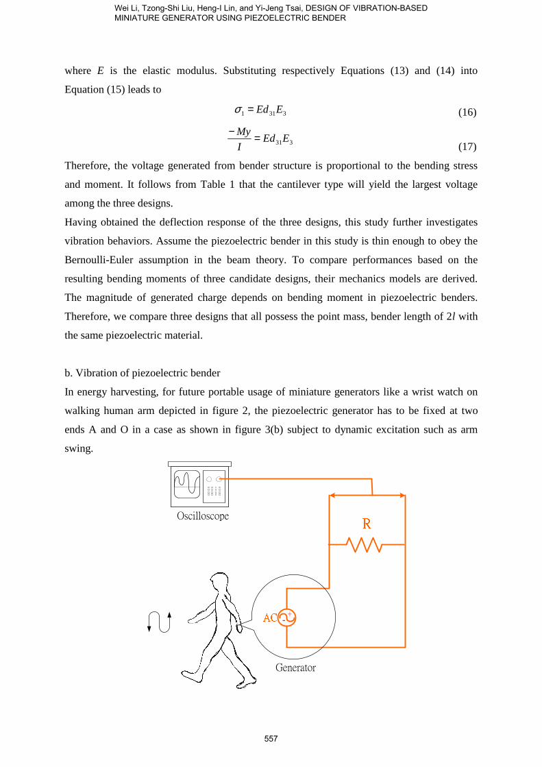
b. Vibration of piezoelectric bender
In energy harvesting, for future portable usage of miniature generators like a wrist watch on
walking human arm depicted in figure 2, the piezoelectric generator has to be fixed at two
ends A and O in a case as shown in figure 3(b) subject to dynamic excitation such as arm
swing.
Oscilloscope
+-
Generator
557
Wei Li, Tzong-Shi Liu, Heng-I Lin, and Yi-Jeng Tsai, DESIGN OF VIBRATION-BASED MINIATURE GENERATOR USING PIEZOELECTRIC BENDER

Figure 2. Portable miniature generator subject to environment vibration in a manner similar
to wrist watch
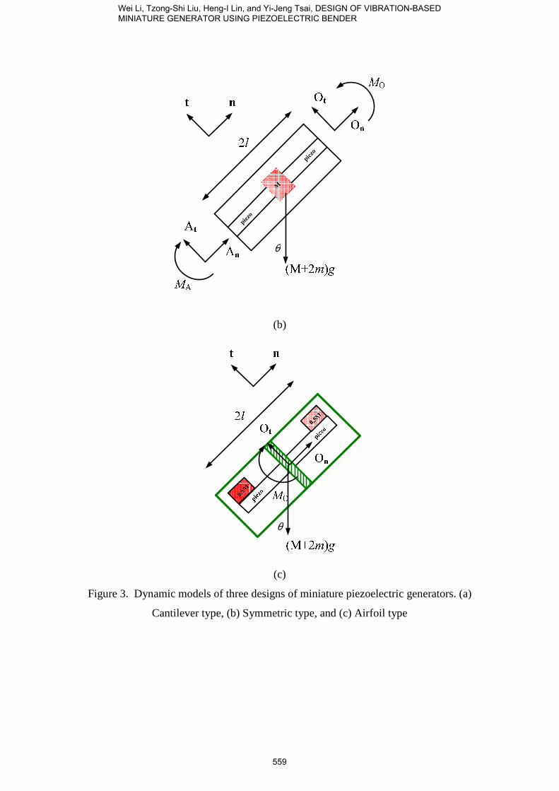
Assume the case as depicted in figures 3 and 4 is endowed with angular acceleration α,
acceleration a, and oblique angle θ with respect to the horizon. Assume that the tangential and
normal forces acting on two ends A and O are At, Ot and An, On, respectively. And the
moments acting on the two ends are MA and MO, respectively. Bending moments can be
derived from three designs as follows.
piezo
M
θ
(a)
558
INTERNATIONAL JOURNAL ON SMART SENSING AND INTELLIGENT SYSTEMS, VOL. 3, NO. 3, SEPTEMBER 2010
M
piezo
piezo
θ
(b)
θ
(c)
Figure 3. Dynamic models of three designs of miniature piezoelectric generators. (a)
Cantilever type, (b) Symmetric type, and (c) Airfoil type
559
Wei Li, Tzong-Shi Liu, Heng-I Lin, and Yi-Jeng Tsai, DESIGN OF VIBRATION-BASED MINIATURE GENERATOR USING PIEZOELECTRIC BENDER
θ
(a)
θ
(b)
560
INTERNATIONAL JOURNAL ON SMART SENSING AND INTELLIGENT SYSTEMS, VOL. 3, NO. 3, SEPTEMBER 2010
θ
M
piezo
piezo
`
(c)
piezo
0.5M
θ
(d)
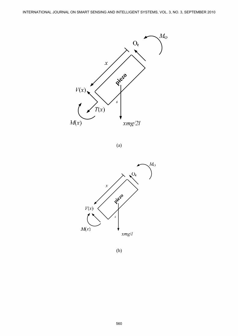
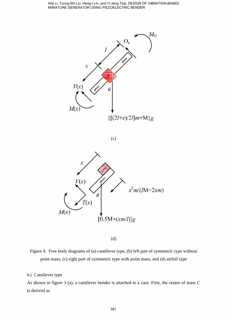
Figure 4. Free body diagrams of (a) cantilever type, (b) left part of symmetric type without
point mass, (c) right part of symmetric type with point mass, and (d) airfoil type
b.i Cantilever type
As shown in figure 3 (a), a cantilever bender is attached to a case. First, the center of mass C
is derived as
561
Wei Li, Tzong-Shi Liu, Heng-I Lin, and Yi-Jeng Tsai, DESIGN OF VIBRATION-BASED MINIATURE GENERATOR USING PIEZOELECTRIC BENDER
m
ml
m
mllC
2M
)M(2
2M
2M2
++=
++=
(18)
where M is the load mass, m is the bender mass, l is the length of bender. The moment
equation is written as
( ) ( ) ( ) αθ 242M3
1
2M
M2sin2M lmM
m
mlgm O +=−
+++
(19)
where g is acceleration of gravity. The force equation in the normal direction is written as
( ) ( ) nn amgmO 2Mcos2M +=+− θ (20)
where an is acceleration in the normal direction and the force equation in the tangential
direction is written as
( ) ( ) tt amOgm 2Msin2M +=−+ θ (21)
where at is acceleration in the tangential direction. According to the free body diagram
depicted in figure 4 (a), one has
( )( ) ( )
−+
++=−+−+ αθθ )22M
)M(2(sinsin2M
x
m
mlam
l
xmg
l
xxVagm tt
(22)
in the tangential direction and one has
( )
−+
++=−−++ 2
22M
M2)(cos)cos)(2M( ωθθ x
m
mla
l
mxxTg
l
mxgam nn
(23)
in the normal direction. Similarly, according to the free body diagram depicted in figure 4 (a),
the bending moment equation can be expressed as
( ) ( ) αθ 2
3
1
2sin x
l
mxM
xg
l
mxxMxxV O =−−+
(24)
Substituting Equation (19) into the force and moment equations, the bending moment
equation can be expressed as
( ) ( ) ( ) ( ) αθθα 22 2M3
4sinM2
2sin
2
3
1lmgml
xg
l
mxxxVx
l
mxxM +−+++−=
(25)
b.ii Symmetric type
As shown in figure 4 (b), in the symmetric design, the bender is attached to a case. In the
same manner as the foregoing, the moment equation is derived as
( ) α22M3
1lmMMlAlO AOtt +=−+−
(26)
and the force equation is written as
( ) ( ) ttt amAOgm 2Msin2M +=−−+ θ (27)
562
INTERNATIONAL JOURNAL ON SMART SENSING AND INTELLIGENT SYSTEMS, VOL. 3, NO. 3, SEPTEMBER 2010

Assuming oδ and oθ are deflection and deflection angle, respectively at end O. There are
three effects acting on the end: (1) tangential force Ot, (2) moment MO, and (3) point mass M
attached to the bender center. Therefore, the deflection and deflection angle at the origin can
respectively be written as
( ) 066
M2
3
8 223
=−−+= lllEI
g
EI
lM
EI
lO Otoδ
(28)
02
M22 22
=−+=EI
gl
EI
lO
EI
lM tOOθ
(29)
Solving Equations (28) and (29) gives
4
MglM o −= ,
2
MgOt =
Substituting the above relationships into Equations (26) and (27) leads to
2
M)sin)(2M(
gagmA tt −−+= θ
(30)
( ) ( )mlg
agmlgl
M tA 2M32
Msin2M
4
M 2
+−
−−+−= αθ (31)
According to the free body diagram depicted in figure 4 (b), one has
( ) ( ) α2
23
1mx
l
xMxxVxM O =−+
(32)
The bending moment equation can be expressed as
( ) ( )xxVgl
xl
xmxM −−=
4
M
23
1 2α (33)
Similarly, according to the free body diagram depicted in figure 4 (c), one has
( ) ( )( ) ( ) α2M2
2
3
1xlm
l
xlMxlxVxM O +
+
+=−++ (34)
Thus, the bending moment equation can be expressed as
( ) ( ) ( )( )4
MM
2
2
3
1 2 glxlxVxlm
l
xlxM −+−+
+
+= α (35)
b.iii Airfoil type
In a similar manner, as shown in figures 3 (c) and 4 (d), the bending moment of the airfoil
type design can also be derived as
563
Wei Li, Tzong-Shi Liu, Heng-I Lin, and Yi-Jeng Tsai, DESIGN OF VIBRATION-BASED MINIATURE GENERATOR USING PIEZOELECTRIC BENDER

( ) ( )
+
+−
+= αθ 22
3
1
2MsinM5.0 x
xml
mxxg
l
xmxM
(36)
Substituting numerical values in Table 2 into Equations (23), (35), and (36) gives Table 3.
According to Table 3, the cantilever design will generate the largest dynamic bending
moment, hence the largest dynamic deformation. As a consequence, the most electric power
will be generated from the cantilever design.
564
INTERNATIONAL JOURNAL ON SMART SENSING AND INTELLIGENT SYSTEMS, VOL. 3, NO. 3, SEPTEMBER 2010

Table 2: Parameters of miniature piezoelectric generator
m 0.397g
masspoint m 1.057g
l 0.042m
ν 0.29
ρ 2800Kg/m3
I 3.78×10⁻¹⁴m4
E 58GPa
Table 3. Comparison of calculated dynamic bending moments (N-m) among three designs
Symmetric Cantilever Airfoil (for one side)
0.0633 0.4203 0.0748
Table 4. Comparison of maximum deflections (m) among three designs
Symmetric Cantilever Airfoil (for one side)
0.0017 0.1104 0.0069
III. NUMERICAL RESULT
For a cantilever beam of the fixed-free end load, the first angular natural frequency is [20]
( ) 3masspoint 23.0
3
mlmm
EIn ⋅+
=ω (37)
where mpoint mass is the load mass, m is the bender mass, l is the length of beam, I is the area
moment of inertia of beam, E is Young’s modulus, and ωn is the angular natural frequency.
The above solution can be compared with the cantilever and airfoil types. Moreover, for a
fixed-fixed beam of a center load, the first angular natural frequency is [20]
( ) 3masspoint 375.0
314
lmm
EIn ⋅+
=ω (38)
565
Wei Li, Tzong-Shi Liu, Heng-I Lin, and Yi-Jeng Tsai, DESIGN OF VIBRATION-BASED MINIATURE GENERATOR USING PIEZOELECTRIC BENDER
where mpoint mass is the load mass, m is the bender mass, l is the beam length, I is the area
moment of inertia for beam, E is Young’s modulus, and ωn is the angular natural frequency.
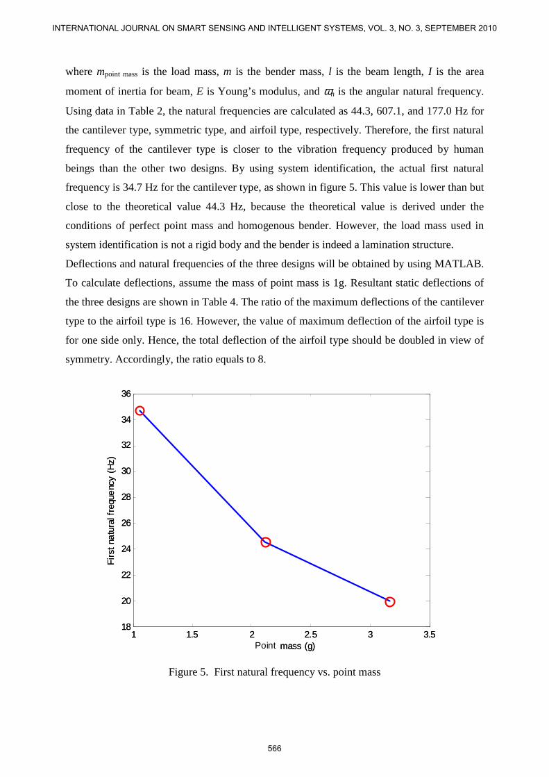
Using data in Table 2, the natural frequencies are calculated as 44.3, 607.1, and 177.0 Hz for
the cantilever type, symmetric type, and airfoil type, respectively. Therefore, the first natural
frequency of the cantilever type is closer to the vibration frequency produced by human
beings than the other two designs. By using system identification, the actual first natural
frequency is 34.7 Hz for the cantilever type, as shown in figure 5. This value is lower than but
close to the theoretical value 44.3 Hz, because the theoretical value is derived under the
conditions of perfect point mass and homogenous bender. However, the load mass used in
system identification is not a rigid body and the bender is indeed a lamination structure.
Deflections and natural frequencies of the three designs will be obtained by using MATLAB.
To calculate deflections, assume the mass of point mass is 1g. Resultant static deflections of
the three designs are shown in Table 4. The ratio of the maximum deflections of the cantilever
type to the airfoil type is 16. However, the value of maximum deflection of the airfoil type is
for one side only. Hence, the total deflection of the airfoil type should be doubled in view of
symmetry. Accordingly, the ratio equals to 8.
1 1.5 2 2.5 3 3.518
20
22
24
26
28
30
32
34
36
System mass (g)
Fir
st n
atu
ral f
requ
enc
y (H
z)
Point1 1.5 2 2.5 3 3.5
18
20
22
24
26
28
30
32
34
36
System mass (g)
Fir
st n
atu
ral f
requ
enc
y (H
z)
Point
Figure 5. First natural frequency vs. point mass
566
INTERNATIONAL JOURNAL ON SMART SENSING AND INTELLIGENT SYSTEMS, VOL. 3, NO. 3, SEPTEMBER 2010
IV. EXPERIMENTAL RESULTS
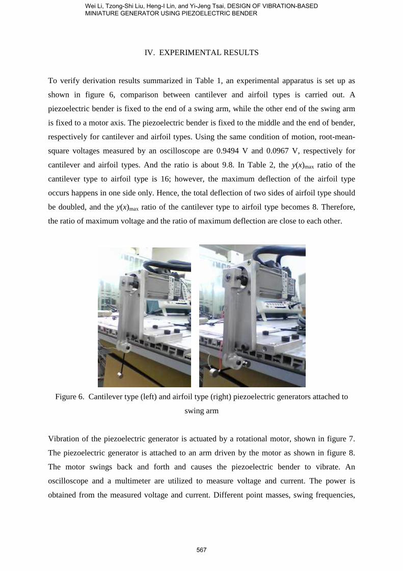
To verify derivation results summarized in Table 1, an experimental apparatus is set up as
shown in figure 6, comparison between cantilever and airfoil types is carried out. A
piezoelectric bender is fixed to the end of a swing arm, while the other end of the swing arm
is fixed to a motor axis. The piezoelectric bender is fixed to the middle and the end of bender,
respectively for cantilever and airfoil types. Using the same condition of motion, root-mean-
square voltages measured by an oscilloscope are 0.9494 V and 0.0967 V, respectively for
cantilever and airfoil types. And the ratio is about 9.8. In Table 2, the y(x)max ratio of the
cantilever type to airfoil type is 16; however, the maximum deflection of the airfoil type
occurs happens in one side only. Hence, the total deflection of two sides of airfoil type should
be doubled, and the y(x)max ratio of the cantilever type to airfoil type becomes 8. Therefore,
the ratio of maximum voltage and the ratio of maximum deflection are close to each other.
Figure 6. Cantilever type (left) and airfoil type (right) piezoelectric generators attached to
swing arm
Vibration of the piezoelectric generator is actuated by a rotational motor, shown in figure 7.
The piezoelectric generator is attached to an arm driven by the motor as shown in figure 8.
The motor swings back and forth and causes the piezoelectric bender to vibrate. An
oscilloscope and a multimeter are utilized to measure voltage and current. The power is
obtained from the measured voltage and current. Different point masses, swing frequencies,
567
Wei Li, Tzong-Shi Liu, Heng-I Lin, and Yi-Jeng Tsai, DESIGN OF VIBRATION-BASED MINIATURE GENERATOR USING PIEZOELECTRIC BENDER
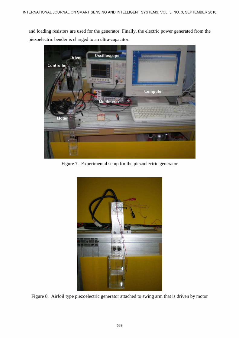
and loading resistors are used for the generator. Finally, the electric power generated from the
piezoelectric bender is charged to an ultra-capacitor.
Figure 7. Experimental setup for the piezoelectric generator
Figure 8. Airfoil type piezoelectric generator attached to swing arm that is driven by motor
568
INTERNATIONAL JOURNAL ON SMART SENSING AND INTELLIGENT SYSTEMS, VOL. 3, NO. 3, SEPTEMBER 2010
Concerning the cantilever type in experiments, the point mass is 0.9g. The swing frequency is
about 15Hz without any loading resistor. The voltage generated is about 120mV and the
power is about 0.156µW.
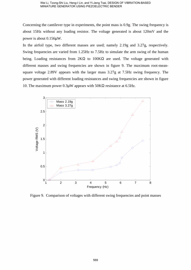
In the airfoil type, two different masses are used; namely 2.19g and 3.27g, respectively.
Swing frequencies are varied from 1.25Hz to 7.5Hz to simulate the arm swing of the human
being. Loading resistances from 2KΩ to 100KΩ are used. The voltage generated with
different masses and swing frequencies are shown in figure 9. The maximum root-mean-
square voltage 2.89V appears with the larger mass 3.27g at 7.5Hz swing frequency. The
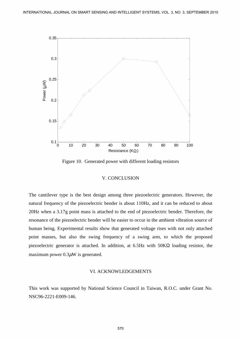
power generated with different loading resistances and swing frequencies are shown in figure
10. The maximum power 0.3µW appears with 50KΩ resistance at 6.5Hz.
1 2 3 4 5 6 7 80
0.5
1
1.5
2
2.5
3
Vol
tage
RM
S (
V)
Frequency (Hz)
Mass 2.19gMass 3.27g
Figure 9. Comparison of voltages with different swing frequencies and point masses
569
Wei Li, Tzong-Shi Liu, Heng-I Lin, and Yi-Jeng Tsai, DESIGN OF VIBRATION-BASED MINIATURE GENERATOR USING PIEZOELECTRIC BENDER
0 10 20 30 40 50 60 70 80 90 1000.1
0.15
0.2
0.25
0.3
0.35
Pow
er (
µW)
Resistance (KΩ)
Figure 10. Generated power with different loading resistors
V. CONCLUSION
The cantilever type is the best design among three piezoelectric generators. However, the
natural frequency of the piezoelectric bender is about 110Hz, and it can be reduced to about
20Hz when a 3.17g point mass is attached to the end of piezoelectric bender. Therefore, the
resonance of the piezoelectric bender will be easier to occur in the ambient vibration source of
human being. Experimental results show that generated voltage rises with not only attached
point masses, but also the swing frequency of a swing arm, to which the proposed
piezoelectric generator is attached. In addition, at 6.5Hz with 50KΩ loading resistor, the
maximum power 0.3µW is generated.
VI. ACKNOWLEDGEMENTS
This work was supported by National Science Council in Taiwan, R.O.C. under Grant No.
NSC96-2221-E009-146.
570
INTERNATIONAL JOURNAL ON SMART SENSING AND INTELLIGENT SYSTEMS, VOL. 3, NO. 3, SEPTEMBER 2010
REFERENCES
[1] S. Roundy, P. K. Wright and K. S. J. Pister, Micro-Electrostatic “Vibration-to-Electricity
Converters”, ASME International Mechanical Engineering Congress & Exposition, vol. 18,
pp.1823-1830. 2002.
[2] C. B. Williams and R. B. Yates, “Analysis of a Micro-Electric Generator for
Microsystems”, Sensors and Actuators, vol. 52, pp. 8-11, 1996.
[3] A. E. Shahat, A. Keyhani and H. E. Shewy, “Micro-generator Design for Smart Grid
System”, International Journal on Smart Sensing and Intelligent Systems, vol. 3, no. 2, pp.
176-216, June 2010.
[4] S. Neduncheliyan, M. Umapathy and D. Ezhilarasi, “Simultaneous Periodic Output
Feedback Control for Piezoelectric Actuated Structures Using Interval Methods”,
International Journal on Smart Sensing and Intelligent Systems, vol. 2, no. 3, pp. 417-431,
September 2009.
[5] V. T. Rathod and D. R. Mahapatra, “Lamb Wave Based Monitoring of Plate-Stiffener
Deboding Using a Circular Array of Piezoelectric Sensors”, International Journal on Smart
Sensing and Intelligent Systems, vol. 3, no. 1, pp. 27-44, March 2010.
[6] E. Matsumoto and Y. Komagome, “Intelligent Structural Elements Covered by
Piezoelectric High-Polymer Film”, International Journal on Smart Sensing and Intelligent
Systems, vol. 1, no. 2, pp. 420-429, June 2008.
[7] T. Starner, “Human-powered Wearable Computing”, IBM Systems Journal, vol. 35, pp.
1898-1902, 1996.
[8] N. S. Shenck and J. A. Paradiso, “Energy Scavenging with Shoe-Mounted Piezoelectrics”,
IEEE Micro, vol. 21, pp. 30-42, 2001.
[9] C. Alippi and C. Galperti, “An Embedded Wireless System for Estimating the Exposition
Risk in First Emergency Management”, International Journal on Smart Sensing and
Intelligent Systems, vol. 1, no. 3, pp. 592-612, September 2008.
[10] S. Roundy and P. K. Wright, “A Piezoelectric Vibration Based Generator for Wireless
Electronics”, Smart Materials and Structures, vol. 13, pp 1131-1142, 2004.
[11] G. B. Hmida, A. L. Ekuakille, A. Kachouri, H. Ghariani, and A. Trotta, “Extracting
Electric Power from Human Body for Supplying Neural Recording System”, International
Journal on Smart Sensing and Intelligent Systems, vol. 2, no. 2, pp. 229-245, June 2009.
571
Wei Li, Tzong-Shi Liu, Heng-I Lin, and Yi-Jeng Tsai, DESIGN OF VIBRATION-BASED MINIATURE GENERATOR USING PIEZOELECTRIC BENDER
[12] E. Koutroulis, K. Kalaitzakis and N. C. Voulgaris, “Development of a Microcontroller-
Based Photovoltaic Maximum Power Point Tracking Control System”, IEEE Transactions on
Power Electronics, vol. 16, pp. 46–54, 2001.
[13] G. K. Ottman, H. F. Hofmann, A. C. Bhatt and G. A. Lesieutre, “Adaptive Piezoelectric
Energy Harvesting Circuit for Wireless Remote Power Supply”, IEEE Transactions on Power
Electronics, vol. 17, pp. 669–676, 2002.
[14] G. K. Ottman, H. F. Hofmann and G. A. Lesieutre, “Optimized Piezoelectric Energy
Harvesting Circuit Using Step-Down Converter in Discontinuous Conduction Mode”, IEEE
Transactions on Power Electronics, vol. 18, pp. 696–703, 2003.
[15] K. Makihara, J. Onoda and T. Miyakawa, “Low Energy Dissipation Electric Circuit for
Energy Harvesting”, Smart Materials and Structures, vol. 15, pp. 1493–1498, 2006.
[16] H. A. Sodando, D. J. Inman and G. Park, “Comparison of Piezoelectric Energy
Harvesting Devices for Recharging Batteries”, Journal of Intelligent Material Systems and
Structures, vol. 16, pp. 799-807, 2005.
[17] H. A. Sodando, D. J. Inman and G. Park, “Generation and Storage of Electricity form
Power Harvesting Device”, Journal of Intelligent Material Systems and Structures, vol. 16, pp.
67-75, 2005.
[18] D. R. Cook and C. W. Young, “Advanced Mechanics of Materials”, Macmillan
Publishing Company, 1985.
[19] G. W. Taylor, J. J. Gagnepain, T. R. Meeker, T. Nakamura and L. A. Shuvalov,
“Piezoelectricity”, Gordon and Breach, Science Publisher, Inc., 1985.
[20] C. M. Harris, “Shock and Vibration Handbook”, McGraw Hill 3rd, 1987.
572
INTERNATIONAL JOURNAL ON SMART SENSING AND INTELLIGENT SYSTEMS, VOL. 3, NO. 3, SEPTEMBER 2010