modeling of power and thermal characteristics of ... · power and thermal characteristics of...
TRANSCRIPT

Modeling of Power and Thermal Characteristics of
Piezoelectric Transformers Safakcan Tuncdemir1
W. Michael Bradley2
Presented at COMSOL Conference, Boston, October 3-5 2012
1 Solid State Ceramics, Williamsport, PA 17701 USA 2 QorTek, Williamsport, PA 17701 USA
Excerpt from the Proceedings of the 2012 COMSOL Conference in Boston

Outline • Piezoelectric Transformer Background
• Piezoelectric Transformer Operating Principle
– Equivalent Circuit and Drive Conditions
– Material Properties and Loss
• Common Issues
– Motivation for Model Development
• COMSOL Model Details
• Results
• Future Work

Merits
• Solid State Devices
• Efficient and High Power Density
• Low-Profile Form Factor
• Low EMI Emission
• No Magnetic Susceptibility
PT Designs in Literature1
Applications
• Computer LED/LCD Backlights
• Florescent Ballast
• Portable Electronic Chargers
• Ignition of Gas-Discharge Lamps
• Compact AC/DC and DC/DC Converters
Piezoelectric Transformer Background
1. J. Yang, “Piezoelectric Transformer Structural Modeling – A Review”, IEEE Trans on UFFC, 54, 6, 1154-70 (2007).

Rosen1 Type Piezoelectric Transformer
1. C. A. Rosen, “Ceramic transformers and filters”, proc. Electronic Comp. Symp., 205-211 (1956)
Electrical Mechanical Mechanical Electrical (N2)
(N0)
(N1) (N0)
Combination of Converse Piezoelectric Effect, Vibration and Direct Piezoelectric Effect
X Y
Z
(N2)
(N1)
(N0)
Input Output
Piezoelectric Transformer Operating Principle
POLLING DIRECTION STRESS ELECTRODE
INPUT
OUTPUT
GND
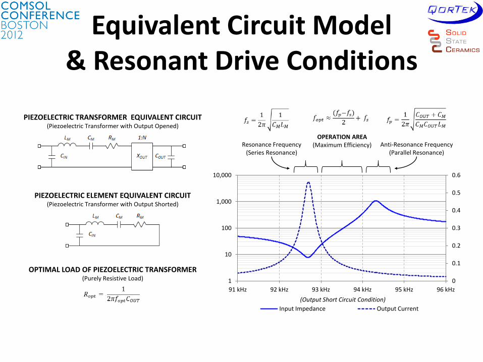
Equivalent Circuit Model & Resonant Drive Conditions
0
0.1
0.2
0.3
0.4
0.5
0.6
1
10
100
1,000
10,000
91 kHz 92 kHz 93 kHz 94 kHz 95 kHz 96 kHz
Input Impedance Output Current
Resonance Frequency (Series Resonance)
Anti-Resonance Frequency (Parallel Resonance)
OPERATION AREA (Maximum Efficiency)
PIEZOELECTRIC TRANSFORMER EQUIVALENT CIRCUIT (Piezoelectric Transformer with Output Opened)
PIEZOELECTRIC ELEMENT EQUIVALENT CIRCUIT (Piezoelectric Transformer with Output Shorted)
OPTIMAL LOAD OF PIEZOELECTRIC TRANSFORMER (Purely Resistive Load)
(Output Short Circuit Condition)

1
66
55
00000
00000
00000
000
000
000
55
331313
131112
131211
E
E
E
E
EEE
EEE
EEE
E c
s
s
s
sss
sss
sss
s
1
33
11
11
00
00
00
T
T
T
T
T
1
333131
15
15
000
00000
00000
Te
ddd
d
d
d
Electromechanical Coupled Physics Elastic Stiffness
Dielectric Permittivity
Piezoelectric Charge Constant )'tan1(* jTT
)'tan1(* jss EE
)'tan1(* jdd
Losses
Material properties and losses are nonlinear at: • High Frequency (Resonance) • High Power • Elevated Temperatures
Material Properties & Loss

• Nonlinear Device • Dependent on:
• Excitation Frequency • Excitation Voltage and Current • Ambient Temperature • Mechanical Loading • Electrical Loading
A fully coupled device model that includes thermal, electrical and mechanical loads is an ideal tool for Piezoelectric Transformer design.
Common Issues

• Because of the thermal-electrical-mechanical coupled physics of Piezoelectric devices we need to build models considering all the peripheral effects.
Motivation for Model Development
• Coupled Physics – Piezoelectric
– Electrical
• Driving
• Load circuit
– Mechanical
• Device holder (fixture)
– Thermal
• Ambient temperature
• System Level – Input (I)
– Output (O)
– Initial Conditions (IC)
Piezoelectric Transformers
I O
BC=IC+PT(t)

COMSOL Model Details • Model Topology
• Electrical Circuit • Structural Mechanics • Heat Transfer
• Model Geometry • PZT-4 • Silicone Supports • Air Cavity

Mechanical Results
• Resonant Mode Shape
– 2nd Longitudinal Mode
– Mounted at Modal Points
Total Displacement (µm) 10k (Load) - 60300Hz (Resonance)
Electric Potential (Volts) 10k (Load) – @ Resonance
Physical Test Sample

Input Impedance Results
• Input Impedance Plot
– COMSOL Model
• Derived Value
– Electrical Test
• Electrical Test
– SPICE
• Parameters Derived from Test Sample Measurement

Temperature Profile Results
• Temperature Profile
– Top Surface
– Thermal Image of Test Sample vs. Model

Future Work
• Implement Fully-Coupled Heat Transfer
– Include Thermal Expansion
– Include Temperature Dependence of Piezoelectric Parameters
• Include effects of Electrode Material
– Thin Mechanical Layer
• Include Effects of Wired Connections

References
1. C. A. Rosen, “Ceramic transformers and filters”, Electronic Comp. Symp., 205-211 (1956)
2. J. Yang, “Piezoelectric Transformer Structural Modeling – A Review”, IEEE Transactions on Ultrasonics, Ferroelectrics and Frequency Control, Vol. 54, No. 6, 1154-1170 (2007).
3. S. Bronshtein, A Abramovitz, A, Bronshtein and I. Katz, “A Method for Parameter Extraction of Piezoelectric Transformers”, Vol. 26, No. 11, 3395-3401 (2011)
4. E. L. Horsley, M. P. Foster and D. A Stone, “State-of-the-art Piezoelectric Transformer technology”, European Conference on Power Electronics and Applications, 1-10 (2007)
5. Manh Cuong Do, “Piezoelectric Transformer Integration Posibility in High Power Density Applications”, Technische Universitat at Dresden (2008)
6. G. E. Martin, Dielectric, “Elastic and Piezoelectric Losses in Piezoelectric Materials”, Proc. Ultrasonics Symp, 613-617 (1974)