chapter 7 fire and smoke protection features
TRANSCRIPT

1
CHAPTER 7 FIRE AND SMOKE PROTECTION FEATURES
User note:
About this chapter: Chapter 7 provides detailed requirements for fire-resistance-rated construction, including structural members, walls, partitions and horizontal assemblies. Other portions of the code describe where certain fire-resistance-rated elements are required. This chapter specifies how these elements are constructed, how openings in walls and partitions are protected and how penetrations of such elements are protected.
SECTION 701
GENERAL 701.1 Scope. The provisions of this chapter shall govern the materials, systems and assemblies used for structural fire resistance and fire-resistance-rated construction separation of adjacent spaces to safeguard against the spread of fire and smoke within a building and the spread of fire to or from buildings.
SECTION 702
MULTIPLE-USE FIRE ASSEMBLIES 702.1 Multiple-use fire assemblies. Fire assemblies that serve multiple purposes in a building shall comply with all of the requirements that are applicable for each of the individual fire assemblies.
SECTION 703
FIRE-RESISTANCE RATINGS AND FIRE TESTS 703.1 Scope. Materials prescribed herein for fire resistance shall conform to the requirements of this chapter. 703.2 Fire resistance. The fire-resistance rating of building elements, components or assemblies shall be determined in accordance with Section 703.2.1 or 703.2.2 without the use of automatic sprinklers or any other fire suppression system being incorporated, or in accordance with Section 703.2.3.
703.2.1 Tested assemblies. A fire-resistance rating of building elements, components or assemblies shall be determined by the test procedures set forth in ASTM E119 or UL 263. The fire-resistance rating of penetrations and fire-resistant joint systems shall be determined in accordance with
Sections 714 and 715, respectively.
703.2.1.1 Nonsymmetrical wall construction. Interior walls and partitions of nonsymmetrical construction shall be tested with both faces exposed to the furnace, and the assigned fire-resistance rating shall be the

2
shortest duration obtained from the two tests conducted in compliance with ASTM E119 or UL 263. Where evidence is furnished to show that the wall was tested with the least fire-resistant side exposed to the furnace, subject to acceptance of the building official, the wall need not be subjected to tests from the opposite side (see Section 705.5 for exterior walls).
703.2.1.2 Combustible components. Combustible aggregates are permitted in gypsum and Portland cement concrete mixtures for fire-resistance-rated construction. Any component material or admixture is permitted in assemblies if the resulting tested assembly meets the fire-resistance test requirements of this code.
703.2.1.3 Restrained classification. Fire-resistance-rated assemblies tested under ASTM E119 or UL 263 shall not be considered to be restrained unless evidence satisfactory to the building official is furnished by the registered design professional showing that the construction qualifies for a restrained classification in accordance with ASTM E119 or UL 263. Restrained construction shall be identified on the construction documents.
703.2.1.4 Supplemental features. Where materials, systems or devices that have not been tested as part of a fire-resistance-rated assembly are incorporated into the building element, component or assembly, sufficient data shall be made available to the building official to show that the required fire-resistance rating is not reduced.
703.2.1.5 Exterior bearing walls. In determining the fire-resistance rating of exterior bearing walls, compliance with the ASTM E119 or UL 263 criteria for unexposed surface temperature rise and ignition of cotton waste due to passage of flame or gases is required only for a period of time corresponding to the required fire-resistance rating of an exterior nonbearing wall with the same fire separation distance, and in a building of the same group. Where the fire-resistance rating determined in accordance with this exception exceeds the fire-resistance rating determined in accordance with ASTM E119 or UL 263, the fire exposure time period, water pressure and application duration criteria for the hose stream test of ASTM E119 or UL 263 shall be based on the fire-resistance rating determined in accordance with this section.
703.2.2 Analytical methods. The fire resistance of building elements , components or assemblies established by an analytical method shall be by any of the methods listed in this section, based on the fire exposure and acceptance criteria specified in ASTM E119 or UL 263.
1. Fire-resistance designs documented in approved sources.
2. Prescriptive designs of fire-resistance-rated building elements, components or
assemblies as prescribed in Section 721.
3. Calculations in accordance with Section 722.

3
4. Engineering analysis based on a comparison of building element, component or assemblies designs having fire-resistance ratings as determined by the test procedures set forth in ASTM E119 or UL 263.
5. Fire-resistance designs certified by an approved agency.
703.2.3 Approved alternate method. The fire resistance of building elements, components or assemblies not complying with Section 703.2.1 or 703.2.2 shall be permitted to be established by an alternative protection method in accordance with Section 104.11.
703.3 Noncombustibility tests. The tests indicated in Section 703.3.1 shall serve as criteria for acceptance of building materials as set forth in Sections 602.2, 602.3 and 602.4 in Types I, II, III and IV construction. The term “noncombustible” does not apply to the flame spread characteristics of interior finish or trim materials. A material shall not be classified as a noncombustible building construction material if it is subject to an increase in combustibility or flame spread beyond the limitations herein established through the effects of age, moisture or other atmospheric conditions.
703.3.1 Noncombustible materials. Materials required to be noncombustible shall be tested in accordance with ASTM E136. Alternately, materials required to be noncombustible shall be tested in accordance with
ASTM E2652 using the acceptance criteria prescribed by ASTM E136.
Exception: Materials having a structural base of noncombustible material as determined in accordance with ASTM E136, or with ASTM E2652 using the acceptance criteria prescribed by ASTM E136, with a surfacing of not more than 0.125 inch (3.18 mm) in thickness having a flame spread index not greater than 50 when tested in accordance with ASTM E84 or UL 723 shall be acceptable as noncombustible.
703.4 Fire-resistance-rated glazing. Fire-resistance-rated glazing, when tested in accordance with ASTM E119 or UL 263 and complying with the requirements of Section 707, shall be permitted. Fire-resistance-rated glazing shall bear a label marked in accordance with Table 716.1(1) issued by an agency and shall be permanently identified on the glazing. 703.5 Marking and identification. Where there is an accessible concealed floor, floor-ceiling or attic space, fire walls, fire barriers, fire partitions, smoke barriers and smoke partitions or any other wall required to have protected openings or penetrations shall be effectively and permanently identified with signs or stenciling in the concealed space. Such identification shall:
1. Be located within 15 feet (4572 mm) of the end of each wall and at intervals not
exceeding 30 feet (9144 mm) measured horizontally along the wall or partition.
2. Include lettering not less than 3 inches (76 mm) in height with a minimum 3/8-inch (9.5
mm) stroke in a contrasting color incorporating the suggested wording, “FIRE AND/OR SMOKE BARRIER—PROTECT ALL OPENINGS,” or other wording.

4
703.6 Determination of noncombustible protection time contribution. The time, in minutes, contributed to the fire-resistance rating by the noncombustible protection of mass timber building elements, components, or assemblies, shall be established through a comparison of assemblies tested using procedures set forth in ASTM E119 or UL 263. The test assemblies shall be identical in construction, loading and materials, other than the noncombustible protection. The two test assemblies shall be tested to the same criteria of structural failure with the following conditions:
1. Test Assembly 1 shall be without protection.
2. Test Assembly 2 shall include the representative noncombustible protection. The
protection shall be fully defined in terms of configuration details, attachment details, joint sealing details, accessories and all other relevant details.
The noncombustible protection time contribution shall be determined by subtracting the fire-
resistance time, in minutes, of Test Assembly 1 from the fire-resistance time, in minutes, of Test Assembly 2. 703.7 Sealing of adjacent mass timber elements. In buildings of Types IV-A, IV-B and IV-C construction, sealant or adhesive shall be provided to resist the passage of air in the following locations:
1. At abutting edges and intersections of mass timber building elements required to be fire-
resistance rated.
2. At abutting intersections of mass timber building elements and building elements of other
materials where both are required to be fire-resistance rated.
Sealants shall meet the requirements of ASTM C920. Adhesives shall meet the requirements of ASTM D3498.
Exception: Sealants or adhesives need not be provided where they are not a required component of a tested fireresistance-rated assembly.
SECTION 704 FIRE-RESISTANCE RATING
OF STRUCTURAL MEMBERS 704.1 Requirements. The fire-resistance ratings of structural members and assemblies shall comply with this section and the requirements for the type of construction as specified in Table 601. The fire-resistance ratings shall be not less than the ratings required for the fire-resistance-rated assemblies supported by the structural members.
Exception: Fire barriers, fire partitions, smoke barriers and horizontal assemblies as provided in Sections 707.5, 708.4, 709.4 and 711.2, respectively.

5
704.2 Column protection. Where columns are required to have protection to achieve a fire-resistance rating, the entire column shall be provided individual encasement protection by protecting it on all sides for the full column height, including connections to other structural members, with materials having the required fire-resistance rating. Where the column extends through a ceiling, the encasement protection shall be continuous from the top of the foundation or floor/ceiling assembly below through the ceiling space to the top of the column.
Exception: Columns that meet the limitations of Section 704.4.1.
704.3 Protection of the primary structural frame other than columns. Members of the primary structural frame other than columns that are required to have protection to achieve a fire-resistance rating and support more than two floors or one floor and roof, or support a load-bearing wall or a nonload-bearing wall more than two stories high, shall be provided individual encasement protection by protecting them on all sides for the full length, including connections to other structural members, with materials having the required fire-resistance rating.
Exception: Individual encasement protection on all sides shall be permitted on all exposed sides provided that the extent of protection is in accordance with the required fire-resistance rating, as determined in Section 703.
704.4 Protection of secondary structural members. Secondary structural members that are required to have protection to achieve a fire-resistance rating shall be protected by individual encasement protection.
704.4.1 Light-frame construction. Studs, columns and boundary elements that are integral elements in walls of light-frame construction and are located entirely between the top and bottom plates or tracks shall be permitted to have required fire-resistance ratings provided by the membrane protection provided for the wall.
704.4.2 Horizontal assemblies. Horizontal assemblies are permitted to be protected with a membrane or ceiling where the membrane or ceiling provides the required fire-resistance rating and is installed in accordance with Section 711.
704.5 Truss protection. The required thickness and construction of fire-resistance-rated assemblies enclosing trusses shall be based on the results of full-scale tests or combinations of tests on truss components or on approved calculations based on such tests that satisfactorily demonstrate that the assembly has the required fire resistance. 704.6 Attachments to structural members. The edges of lugs, brackets, rivets and bolt heads attached to structural members shall be permitted to extend to within 1 inch (25 mm) of the surface of the fire protection.
704.6.1 Secondary attachments to structural members. Where primary and secondary structural steel members require fire protection, secondary steel attachments to those structural members shall be protected with the same fire-resistive material and thickness as required for the structural member. The protection shall extend

6
away from the structural member a distance of not less than 12 inches (305 mm), or shall be applied to the entire length where the attachment is less than 12 inches (305 mm) long. Where an attachment is hollow and the ends are open, the fire-resistive material and thickness shall be applied to both exterior and interior of the hollow steel attachment.
704.7 Reinforcing. Thickness of protection for concrete or masonry reinforcement shall be measured to the outside of the reinforcement except that stirrups and spiral reinforcement ties are permitted to project not more than 0.5 inch (12.7 mm) into the protection. 704.8 Embedments and enclosures. Pipes, wires, conduits, ducts or other service facilities shall not be embedded in the required fire protective covering of a structural member that is required to be individually encased. 704.9 Impact protection. Where the fire protective covering of a structural member is subject to impact damage from moving vehicles, the handling of merchandise or other activity, the fire protective covering shall be protected by corner guards or by a substantial jacket of metal or other noncombustible material to a height adequate to provide full protection, but not less than 5 feet (1524 mm) from the finished floor.
Exception: Corner protection is not required on concrete columns in parking garages.
704.10 Exterior structural members. Load-bearing structural members located within the exterior walls or on the outside of a building or structure shall be provided with the highest fire-resistance rating as determined in accordance with the following:
1. As required by Table 601 for the type of building element based on the type of
construction of the building.
2. As required by Table 601 for exterior bearing walls based on the type of construction.
3. As required by Table 705.5 for exterior walls based on the fire separation distance.
704.11 Bottom flange protection. Fire protection is not required at the bottom flange of lintels, shelf angles and plates, spanning not more than 6 feet 4 inches (1931 mm) whether part of the primary structural frame or not, and from the bottom flange of lintels, shelf angles and plates not part of the structural frame, regardless of span. 704.12 Seismic isolation systems. Fire-resistance ratings for the isolation system shall meet the fire-resistance rating required for the columns, walls or other structural elements in which the isolation system is installed in accordance with Table 601. Isolation systems required to have a fire-resistance rating shall be protected with approved materials or construction assemblies designed to provide the same degree of fire resistance as the structural element in which the system is installed when tested in accordance with ASTM E119 or UL 263 (see Section 703.2).
7
Such isolation system protection applied to isolator units shall be capable of retarding the transfer of heat to the isolator unit in such a manner that the required gravity load-carrying capacity of the isolator unit will not be impaired after exposure to the standard time-temperature curve fire test prescribed in ASTM E119 or UL 263 for a duration not less than that required for the fire-resistance rating of the structure element in which the system is installed.
Such isolation system protection applied to isolator units shall be suitably designed and
securely installed so as not to dislodge, loosen, sustain damage or otherwise impair its ability to accommodate the seismic movements for which the isolator unit is designed and to maintain its integrity for the purpose of providing the required fire-resistance protection. 704.13 Sprayed fire-resistant materials (SFRM). Sprayed fire-resistant materials (SFRM) shall comply with Sections 704.13.1 through 704.13.5.
704.13.1 Fire-resistance rating. The application of SFRM shall be consistent with the fire-resistance rating and the listing, including, but not limited to, minimum thickness and dry density of the applied SFRM, method of application, substrate surface conditions and the use of bonding adhesives, sealants, reinforcing or other materials.
704.13.2 Manufacturer’s installation instructions. The application of SFRM shall be in accordance with the manufacturer’s installation instructions. The instructions shall include, but are not limited to, substrate temperatures and surface conditions and SFRM handling, storage, mixing, conveyance, method of application, curing and ventilation.
704.13.3 Substrate condition. The SFRM shall be applied to a substrate in compliance with Sections 704.13.3.1 and 704.13.3.2.
704.13.3.1 Surface conditions. Substrates to receive SFRM shall be free of dirt, oil, grease, release agents, loose scale and any other condition that prevents adhesion. The substrates shall be free of primers, paints and encapsulants other than those fire tested and listed by a nationally recognized testing agency. Primed, painted or encapsulated steel shall be allowed, provided that testing has demonstrated that required adhesion is maintained.
704.13.3.2 Primers, paints and encapsulants. Where the SFRM is to be applied over primers, paints or encapsulants other than those specified in the listing, the material shall be field tested in accordance with ASTM E736. Where testing of the SFRM with primers, paints or encapsulants demonstrates that required adhesion is maintained, SFRM shall be permitted to be applied to primed, painted or encapsulated wide flange steel shapes in accordance with the following conditions:
1. The beam flange width does not exceed 12 inches (305 mm); or
2. The column flange width does not exceed 16 inches (400 mm); or
3. The beam or column web depth does not exceed 16 inches (400 mm).

8
4. The average and minimum bond strength values shall be determined based on
not fewer than five bond tests conducted in accordance with ASTM E736. Bond tests conducted in accordance with ASTM E736 shall indicate an average bond strength of not less than 80 percent and an individual bond strength of not less than 50 percent, when compared to the bond strength of the SFRM as applied to
clean, uncoated 1/8-inch-thick (3.2 mm) steel plate.
704.13.4 Temperature. A minimum ambient and substrate temperature of 40°F (4.44°C) shall be maintained during and for not fewer than 24 hours after the application of the SFRM, unless the manufacturer’s instructions allow otherwise.
704.13.5 Finished condition. The finished condition of SFRM applied to structural members or assemblies shall not, upon complete drying or curing, exhibit cracks, voids, spalls, delamination or any exposure of the substrate. Surface irregularities of SFRM shall be deemed acceptable.
SECTION 705
EXTERIOR WALLS 705.1 General. Exterior walls shall comply with this section. 705.2 Projections. Cornices, eave overhangs, exterior balconies and similar projections extending beyond the exterior wall shall conform to the requirements of this section and Section 1405. Exterior egress balconies and exterior exit stairways and ramps shall comply with Sections 1021 and 1027, respectively. Projections shall not extend any closer to the line used to determine the fire separation distance than shown in Table 705.2.
Exception: Buildings on the same lot and considered as portions of one building in accordance with Section 705.3 are not required to comply with this section for projections between the buildings.
TABLE 705.2 MINIMUM DISTANCE OF PROJECTION
FIRE SEPARATION DISTANCE
(FSD) (feet) MINIMUM DISTANCE FROM LINE
USED TO DETERMINE FSD
0 to less than 2 Projections not permitted
2 to less than 3 24 inches
3 to less than 5 Two-thirds of FSD
5 or greater 40 inches
For SI: 1 foot = 304.8 mm; 1 inch = 25.4 mm.
9
705.2.1 Types I and II construction. Projections from walls of Type I or II construction shall be of noncombustible materials or combustible materials as allowed by Sections 705.2.3.1 and 705.2.4.
705.2.2 Type III, IV or V construction. Projections from walls of Type III, IV or V construction shall be of any approved material.
705.2.3 Projection protection. Projections extending to within 5 feet (1524 mm) of the line used to determine the fire separation distance shall be one of the following:
1. Noncombustible materials.
2. Combustible materials of not less than 1-hour fire-resistance-rated construction.
3. Heavy timber construction complying with Section 2304.11.
4. Fire-retardant-treated wood.
5. As permitted by Section 705.2.3.1.
Exception: Type VB construction shall be allowed for combustible projections in Group R-3 and U occupancies with a fire separation distance greater than or equal to 5 feet (1524 mm).
705.2.3.1 Balconies and similar projections. Balconies and similar projections of combustible construction other than fire-retardant-treated wood shall be fire-resistance rated where required by Table 601 for floor construction or shall be of heavy timber construction in accordance with Section 2304.11. The aggregate length of the projections shall not exceed 50 percent of the building’s perimeter on each floor.
Exceptions:
1. On buildings of Types I and II construction, three stories or less above grade
plane, fire-retardant-treated wood shall be permitted for balconies, porches, decks and exterior stairways not used as required exits.
2. Untreated wood and plastic composites that comply with ASTM D7032 and
Section 2612 are permitted for pickets, rails and similar guard components that are limited to 42 inches (1067 mm) in height.
3. Balconies and similar projections on buildings of Types III, IV and V
construction shall be permitted to be of Type V construction and shall not be required to have a fire-resistance rating where sprinkler protection is extended to these areas.
4. Where sprinkler protection is extended to the balcony areas, the aggregate
length of the balcony on each floor shall not be limited.

10
705.2.4 Bay and oriel windows. Bay and oriel windows constructed of combustible materials shall conform to the type of construction required for the building to which they are attached.
Exception: Fire-retardant-treated wood shall be permitted on buildings three stories or less above grade plane of Type I, II, III or IV construction.
705.3 Buildings on the same lot. For the purposes of determining the required wall and opening protection, projections and roof-covering requirements, buildings on the same lot shall be assumed to have an imaginary line between them.
Where a new building is to be erected on the same lot as an existing building, the location of
the assumed imaginary line with relation to the existing building shall be such that the exterior wall and opening protection of the existing building meet the criteria as set forth in Sections 705.5 and 705.8.
Exceptions:
1. Two or more buildings on the same lot shall be either regulated as separate buildings
or shall be considered as portions of one building if the aggregate area of such buildings is within the limits specified in Chapter 5 for a single building. Where the buildings contain different occupancy groups or are of different types of construction, the area shall be that allowed for the most restrictive occupancy or construction.
2. Where an S-2 parking garage of Construction Type I or IIA is erected on the same lot
as a Group R-2 building, and there is no fire separation distance between these buildings, then the adjoining exterior walls between the buildings are permitted to have occupant use openings in accordance with Section 706.8. However, opening protectives in such openings shall only be required in the exterior wall of the S-2 parking garage, not in the exterior wall openings in the R-2 building, and these opening protectives in the exterior wall of the S-2 parking garage shall be not less
than 11/2-hour fire protection rating.
705.4 Materials. Exterior walls shall be of materials permitted by the building’s type of construction. 705.5 Fire-resistance ratings. Exterior walls shall be fire-resistance rated in accordance with Table 601, based on the type of construction, and Table 705.5, based on the fire separation distance. The required fire-resistance rating of exterior walls with a fire separation distance of greater than 10 feet (3048 mm) shall be rated for exposure to fire from the inside. The required fire-resistance rating of exterior walls with a fire separation distance of less than or equal to 10 feet (3048 mm) shall be rated for exposure to fire from both sides.

11
TABLE 705.5 FIRE-RESISTANCE RATING REQUIREMENTS FOR EXTERIOR WALLS BASED ON FIRE
SEPARATION DISTANCEa, d, g
FIRE SEPARATION DISTANCE =
X (feet)
TYPE OF CONSTRUCTION
OCCUPANCY
GROUP He
OCCUPANCY GROUP F-1, M,
S-1f
OCCUPANCY GROUP A, B,
E, F-2, I, Ri, S-2,
Uh
X < 5b All 3 2 1
5X < 10 IA, IVA 3 2 1
Others 2 1 1
10 X < 30 IA, IB, IVA, IVB 2 1 1c
IIB, VB 1 0 0
Others 1 1 1c
X 30 All 0 0 0
For SI: 1 foot = 304.8 mm. a. Load-bearing exterior walls shall also comply with the fire-resistance rating requirements of Table 601. b. See Section 706.1.1 for party walls. c. Open parking garages complying with Section 406 shall not be required to have a fire-resistance rating. d. The fire-resistance rating of an exterior wall is determined based upon the fire separation distance of the exterior
wall and the story in which the wall is located. e. For special requirements for Group H occupancies, see Section 415.6. f. For special requirements for Group S aircraft hangars, see Section 412.3.1. g. Where Table 705.8 permits nonbearing exterior walls with unlimited area of unprotected openings, the required
fire-resistance rating for the exterior walls is 0 hours. h. For a building containing only a Group U occupancy private garage or carport, the exterior wall shall not be
required to have a fire-resistance rating where the fire separation distance is 5 feet (1523 mm) or greater. i. For a Group R-3 building of Type II-B or Type V-B construction, the exterior wall shall not be required to have a
fire-resistance rating where the fire separation distance is 5 feet (1523 mm) or greater.
705.6 Structural stability. Exterior walls shall extend to the height required by Section 705.11. Interior structural elements that brace the exterior wall but that are not located within the plane of the exterior wall shall have the minimum fire-resistance rating required in Table 601 for that structural element. Structural elements that brace the exterior wall but are located outside of the exterior wall or within the plane of the exterior wall shall have the minimum fire-resistance rating required in Table 601 and Table 705.5 for the exterior wall. 705.7 Unexposed surface temperature. Where protected openings are not limited by Section 705.8, the limitation on the rise of temperature on the unexposed surface of exterior walls as required by ASTM E119 or UL 263 shall not apply. Where protected openings are limited by Section 705.8, the limitation on the rise of temperature on the unexposed surface of exterior walls as required by ASTM E119 or UL 263 shall not apply provided that a correction is made for radiation from the unexposed exterior wall surface in accordance with the following formula:
Ae
= A + (Af × F
eo) (Equation 7-1)
where:

12
Ae = Equivalent area of protected openings.
A = Actual area of protected openings. A
f = Area of exterior wall surface in the story under
consideration exclusive of openings, on which the temperature limitations of ASTM E119 or UL 263 for walls are exceeded.
Feo
= An “equivalent opening factor” derived from Figure 705.7 based on the average temperature of the unexposed wall surface and the fire-resistance rating of the wall.
For SI:°C = [(°F) - 32] / 1.8.
FIGURE 705.7 EQUIVALENT OPENING FACTOR
705.8 Openings. Openings in exterior walls shall comply with Sections 705.8.1 through 705.8.6.

13
TABLE 705.8 MAXIMUM AREA OF EXTERIOR WALL OPENINGS BASED ON
FIRE SEPARATION DISTANCE AND DEGREE OF OPENING PROTECTION
FIRE SEPARATION DISTANCE (feet)
DEGREE OF OPENING PROTECTION ALLOWABLE AREAa
0 to less than 3b, c, k
Unprotected, Nonsprinklered (UP, NS) Not Permittedk
Unprotected, Sprinklered (UP, S)i Not Permitted
k
Protected (P) Not Permittedk
3 to less than 5d, e
Unprotected, Nonsprinklered (UP, NS) Not Permitted
Unprotected, Sprinklered (UP, S)i 15%
Protected (P) 15%
5 to less than 10e, f, j
Unprotected, Nonsprinklered (UP, NS) 10%h
Unprotected, Sprinklered (UP, S)i 25%
Protected (P) 25%
10 to less than 15e, f, g, j
Unprotected, Nonsprinklered (UP, NS) 15%h
Unprotected, Sprinklered (UP, S)i 45%
Protected (P) 45%
15 to less than 20f, g, j
Unprotected, Nonsprinklered (UP, NS) 25%
Unprotected, Sprinklered (UP, S)i 75%
Protected (P) 75%
20 to less than 25f, g, j
Unprotected, Nonsprinklered (UP, NS) 45%
Unprotected, Sprinklered (UP, S)i No Limit
Protected (P) No Limit
25 to less than 30f, g, j
Unprotected, Nonsprinklered (UP, NS) 70%
Unprotected, Sprinklered (UP, S)i No Limit
Protected (P) No Limit
30 or greater
Unprotected, Nonsprinklered (UP, NS) No Limit
Unprotected, Sprinklered (UP, S)i No Limit
Protected (P) No Limit
For SI: 1 foot = 304.8 mm. UP, NS = Unprotected openings in buildings not equipped throughout with an automatic sprinkler system in
accordance with Section 903.3.1.1. UP, S = Unprotected openings in buildings equipped throughout with an automatic sprinkler system in accordance
with Section 903.3.1.1. P = Openings protected with an opening protective assembly in accordance with Section 705.8.2. a. Values indicated are the percentage of the area of the exterior wall, per story. b. For the requirements for fire walls of buildings with differing heights, see Section 706.6.1. c. For openings in a fire wall for buildings on the same lot, see Section 706.8. d. The maximum percentage of unprotected and protected openings shall be 25 percent for Group R-3
occupancies. e. Unprotected openings shall not be permitted for openings with a fire separation distance of less than 15 feet for
Group H-2 and H-3 occupancies. f. The area of unprotected and protected openings shall not be limited for Group R-3 occupancies, with a fire
separation distance of 5 feet or greater. g. The area of openings in an open parking structure with a fire separation distance of 10 feet or greater shall not
be limited. h. Includes buildings accessory to Group R-3. i. Not applicable to Group H-1, H-2 and H-3 occupancies. j. The area of openings in a building containing only a Group U occupancy private garage or carport with a fire
separation distance of 5 feet or greater shall not be limited.

14
k. For openings between S-2 parking garage and Group R-2 building, see Section 705.3, Exception 2.
705.8.1 Allowable area of openings. The maximum area of unprotected and protected openings permitted in an exterior wall in any story of a building shall not exceed the percentages specified in Table 705.8 based on the fire separation distance of each individual story.
Exceptions:
1. In other than Group H occupancies, unlimited unprotected openings are permitted in the first story above grade plane where the wall faces one of the following:
1.1. A street and has a fire separation distance of more than 15 feet (4572 mm).
1.2. An unoccupied space. The unoccupied space shall be on the same lot or dedicated for public use, shall be not less than 30 feet (9144 mm) in width and shall have access from a street by a posted fire lane in accordance with the International Fire Code.
2. Buildings whose exterior bearing walls, exterior nonbearing walls and exterior primary structural frame are not required to be fire-resistance rated shall be permitted to have unlimited unprotected openings.
705.8.2 Protected openings. Where openings are required to be protected, opening protectives shall comply with Section 716.
Exception: Opening protectives are not required where the building is equipped throughout with an automatic sprinkler system in accordance with Section 903.3.1.1 and the exterior openings are protected by a water curtain using automatic sprinklers approved for that use.
705.8.3 Unprotected openings. Where unprotected openings are permitted, windows and doors shall be constructed of any approved materials. Glazing shall conform to the requirements of Chapters 24 and 26.
705.8.4 Mixed openings. Where both unprotected and protected openings are located in the exterior wall in any story of a building, the total area of openings shall be determined in accordance with the following:
(Ap/a
p) + (A
u/a
u) 1 (Equation 7-2)
Ap = Actual area of protected openings, or the equivalent area
of protected openings, Ae (see Section 705.7).
ap = Allowable area of protected openings.
Au = Actual area of unprotected openings.
15
au = allowable area of unprotected openings.
705.8.5 Vertical separation of openings. Openings in exterior walls in adjacent stories shall be separated vertically to protect against fire spread on the exterior of the buildings where the openings are within 5 feet (1524 mm) of each other horizontally and the opening in the lower story is not a protected opening with
a fire protection rating of not less than 3/4 hour. Such openings shall be separated vertically
not less than 3 feet (914 mm) by spandrel girders, exterior walls or other similar assemblies that have a fire-resistance rating of not less than 1 hour, rated for exposure to fire from both sides, or by flame barriers that extend horizontally not less than 30 inches (762 mm) beyond the exterior wall. Flame barriers shall have a fire-resistance rating of not less than 1 hour. The unexposed surface temperature limitations specified in ASTM E119 or UL 263 shall not apply to the flame barriers unless otherwise required by the provisions of this code.
Exceptions:
1. This section shall not apply to buildings that are three stories or less above grade
plane.
2. This section shall not apply to buildings equipped throughout with an automatic sprinkler system in accordance with Section 903.3.1.1 or 903.3.1.2.
3. Open parking garages.
705.8.6 Vertical exposure. For buildings on the same lot, opening protectives having a fire protection rating of not less
than 3/4 hour shall be provided in every opening that is less than 15 feet (4572 mm) vertically
above the roof of an adjacent building or structure based on assuming an imaginary line between them. The opening protectives are required where the fire separation distances from the imaginary line to each building or structure are less than 15 feet (4572 mm).
Exceptions:
1. Opening protectives are not required where the roof assembly of the adjacent
building or structure has a fire-resistance rating of not less than 1 hour for a minimum distance of 10 feet (3048 mm) from the exterior wall facing the imaginary line and the entire length and span of the supporting elements for the fire-resistance-rated roof assembly has a fire-resistance rating of not less than 1 hour.
2. Buildings on the same lot and considered as portions of one building in
accordance with Section 705.3 are not required to comply with Section 705.8.6. 705.9 Joints. Joints made in or between exterior walls required by this section to have a fire-resistance rating shall comply with Section 715.
Exception: Joints in exterior walls that are permitted to have unprotected openings.

16
705.9.1 Voids. The void created at the intersection of a floor/ceiling assembly and an exterior curtain wall assembly shall be protected in accordance with Section 715.4.
705.10 Ducts and air transfer openings. Penetrations by air ducts and air transfer openings in fire-resistance-rated exterior walls required to have protected openings shall comply with Section 717.
Exception: Foundation vents installed in accordance with this code are permitted.
705.11 Parapets. Parapets shall be provided on exterior walls of buildings.
Exceptions: A parapet need not be provided on an exterior wall where any of the following conditions exist:
1. The wall is not required to be fire-resistance rated in accordance with Table 705.5
because of fire separation distance.
2. The building has an area of not more than 1,000 square feet (93 m2) on any floor.
3. Walls that terminate at roofs of not less than 2-hour fire-resistance-rated construction
or where the roof, including the deck or slab and supporting construction, is constructed entirely of noncombustible materials.
4. One-hour fire-resistance-rated exterior walls that terminate at the underside of the
roof sheathing, deck or slab, provided that:
4.1. Where the roof/ceiling framing elements are parallel to the walls, such
framing and elements supporting such framing shall not be of less than 1-hour fire-resistance-rated construction for a width of 4 feet (1220 mm) for Groups R and U and 10 feet (3048 mm) for other occupancies, measured from the interior side of the wall.
4.2. Where roof/ceiling framing elements are not parallel to the wall, the entire
span of such framing and elements supporting such framing shall not be of less than 1-hour fire-resistance-rated construction.
4.3. Openings in the roof shall not be located within 5 feet (1524 mm) of the 1-
hour fire-resistance-rated exterior wall for Groups R and U and 10 feet (3048 mm) for other occupancies, measured from the interior side of the wall.
4.4. The entire building shall be provided with not less than a Class B roof
covering.
5. In Groups R-2 and R-3 where the entire building is provided with a Class C roof
covering, the exterior wall shall be permitted to terminate at the underside of the roof

17
sheathing or deck in Types III, IV and V construction, provided that one or both of the following criteria is met:
5.1. The roof sheathing or deck is constructed of approved noncombustible
materials or of fire-retardant-treated wood for a distance of 4 feet (1220 mm).
5.2. The roof is protected with 0.625-inch (16 mm) Type X gypsum board
directly beneath the underside of the roof sheathing or deck, supported by not less than nominal 2-inch (51 mm) ledgers attached to the sides of the roof framing members for a minimum distance of 4 feet (1220 mm).
6. Where the wall is permitted to have not less than 25 percent of the exterior wall
areas containing unprotected openings based on fire separation distance as determined in accordance with Section 705.8.
705.11.1 Parapet construction. Parapets shall have the same fire-resistance rating as that required for the supporting wall, and on any side adjacent to a roof surface, shall have noncombustible faces for the uppermost 18 inches (457 mm), including counterflashing and coping materials. The height of the parapet shall be not less than 30 inches (762 mm) above the point where the roof surface and the wall intersect. Where the roof slopes toward a parapet at a slope greater than 2 units vertical in 12 units horizontal (16.7-percent slope), the parapet shall extend to the same height as any portion of the roof within a fire separation distance where protection of wall openings is required, but the height shall be not less than 30 inches (762 mm).
SECTION 706 FIRE WALLS
706.1 General. Fire walls shall be constructed in accordance with Sections 706.2 through 706.11. The extent and location of such fire walls shall provide a complete separation. Where a fire wall separates occupancies that are required to be separated by a fire barrier wall, the most restrictive requirements of each separation shall apply.
706.1.1 Party walls. Any wall located on a lot line between adjacent buildings, which is used or adapted for joint service between the two buildings, shall be constructed as a fire wall in accordance with Section 706. Party walls shall be constructed without openings and shall create separate buildings.
Exceptions:
1. Openings in a party wall separating an anchor building and a mall shall be in
accordance with Section 402.4.2.2.1.
2. Party walls and fire walls are not required on lot lines dividing a building for
ownership purposes where the aggregate height and area of the portions of the building located on both sides of the lot line do not exceed the maximum height and area requirements of this code. For the building official’s review and

18
approval, the official shall be provided with copies of dedicated access easements and contractual agreements that permit the owners of portions of the building located on either side of the lot line access to the other side for purposes of maintaining fire and life safety systems necessary for the operation of the building.
706.2 Structural stability. Fire walls shall be designed and constructed to allow collapse of the structure on either side without collapse of the wall under fire conditions. Fire walls designed and constructed in accordance with NFPA 221 shall be deemed to comply with this section.
Exception: In Seismic Design Categories D through F, where double fire walls are used in
accordance with NFPA 221, floor and roof sheathing not exceeding 3/4 inch (19.05 mm)
thickness shall be permitted to be continuous through the wall assemblies of light frame construction.
706.3 Materials. Fire walls shall be of any approved noncombustible materials.
Exception: Buildings of Type V construction.
706.4 Fire-resistance rating. Fire walls shall have a fire-resistance rating of not less than that required by Table 706.4.
TABLE 706.4 FIRE WALL FIRE-RESISTANCE RATINGS
GROUP FIRE-RESISTANCE RATING (hours)
A, B, E, H-4, I, R-1, R-2, U 3a
F-1, H-3b, H-5, M, S-1 3
H-1, H-2 4b
F-2, S-2, R-3, R-4 2
a. In Type II or V construction, walls shall be permitted to have a 2-hour fire-resistance rating. b. For Group H-1, H-2 or H-3 buildings, also see Sections 415.7 and 415.8.
706.5 Horizontal continuity. Fire walls shall be continuous from exterior wall to exterior wall and shall extend not less than 18 inches (457 mm) beyond the exterior surface of exterior walls.
Exceptions:
1. Fire walls shall be permitted to terminate at the interior surface of combustible
exterior sheathing or siding provided that the exterior wall has a fire-resistance rating of not less than 1 hour for a horizontal distance of not less than 4 feet (1220 mm) on

19
both sides of the fire wall. Openings within such exterior walls shall be protected by
opening protectives having a fire protection rating of not less than 3/4 hour.
2. Fire walls shall be permitted to terminate at the interior surface of noncombustible
exterior sheathing, exterior siding or other noncombustible exterior finishes provided that the sheathing, siding or other exterior noncombustible finish extends a horizontal distance of not less than 4 feet (1220 mm) on both sides of the fire wall.
3. Fire walls shall be permitted to terminate at the interior surface of noncombustible
exterior sheathing where the building on each side of the fire wall is protected by an automatic sprinkler system installed in accordance with Section 903.3.1.1 or 903.3.1.2.
706.5.1 Exterior walls. Where the fire wall intersects exterior walls, the fire-resistance rating and opening protection of the exterior walls shall comply with one of the following:
1. The exterior walls on both sides of the fire wall shall have a 1-hour fire-resistance
rating with 3/4-hour protection where opening protection is required by Section 705.8.
The fire-resistance rating of the exterior wall shall extend not less than 4 feet (1220 mm) on each side of the intersection of the fire wall to exterior wall. Exterior wall intersections at fire walls that form an angle equal to or greater than 180 degrees (3.14 rad) do not need exterior wall protection.
2. Buildings or spaces on both sides of the intersecting fire wall shall assume to have
an imaginary lot line at the fire wall and extending beyond the exterior of the fire wall. The location of the assumed line in relation to the exterior walls and the fire wall shall be such that the exterior wall and opening protection meet the requirements set forth in Sections 705.5 and 705.8. Such protection is not required for exterior walls terminating at fire walls that form an angle equal to or greater than 180 degrees (3.14 rad).
706.5.2 Horizontal projecting elements. Fire walls shall extend to the outer edge of horizontal projecting elements such as balconies, roof overhangs, canopies, marquees and similar projections that are within 4 feet (1220 mm) of the fire wall.
Exceptions:
1. Horizontal projecting elements without concealed spaces, provided that the
exterior wall behind and below the projecting element has not less than 1-hour fire-resistance-rated construction for a distance not less than the depth of the projecting element on both sides of the fire wall. Openings within such exterior walls shall be protected by opening protectives having a fire protection rating of
not less than 3/4 hour.

20
2. Noncombustible horizontal projecting elements with concealed spaces, provided that a minimum 1-hour fire-resistance-rated wall extends through the concealed space. The projecting element shall be separated from the building by not less than 1-hour fire-resistance-rated construction for a distance on each side of the fire wall equal to the depth of the projecting element. The wall is not required to extend under the projecting element where the building exterior wall is not less than 1-hour fire-resistance rated for a distance on each side of the fire wall equal to the depth of the projecting element. Openings within such exterior walls shall be protected by opening protectives having a fire protection rating of not less
than 3/4 hour.
3. For combustible horizontal projecting elements with concealed spaces, the fire
wall need only extend through the concealed space to the outer edges of the projecting elements. The exterior wall behind and below the projecting element shall be of not less than 1-hour fire-resistance-rated construction for a distance not less than the depth of the projecting elements on both sides of the fire wall. Openings within such exterior walls shall be protected by opening protectives
having a fire protection rating of not less than 3/4 hour.
706.6 Vertical continuity. Fire walls shall extend from the foundation to a termination point not less than 30 inches (762 mm) above both adjacent roofs.
Exceptions:
1. Stepped buildings in accordance with Section 706.6.1.
2. Two-hour fire-resistance-rated walls shall be permitted to terminate at the underside
of the roof sheathing, deck or slab, provided that:
2.1. The lower roof assembly within 4 feet (1220 mm) of the wall has not less than a 1-hour fire-resistance rating and the entire length and span of supporting elements for the rated roof assembly has a fire-resistance rating of not less than 1 hour.
2.2. Openings in the roof shall not be located within 4 feet (1220 mm) of the fire
wall.
2.3. Each building shall be provided with not less than a Class B roof covering.
3. Walls shall be permitted to terminate at the underside of noncombustible roof
sheathing, deck or slabs where both buildings are provided with not less than a Class B roof covering. Openings in the roof shall not be located within 4 feet (1220 mm) of the fire wall.
4. In buildings of Types III, IV and V construction, walls shall be permitted to terminate
at the underside of combustible roof sheathing or decks, provided that all of the following requirements are met:

21
4.1. Roof openings are not less than 4 feet (1220 mm) from the fire wall.
4.2. The roof is covered with a minimum Class B roof covering.
4.3. The roof sheathing or deck is constructed of fire-retardant-treated wood for a
distance of 4 feet (1220 mm) on both sides of the wall or the roof is protected
with 5/8-inch (15.9 mm) Type X gypsum board directly beneath the underside
of the roof sheathing or deck, supported by not less than 2-inch (51 mm) nominal ledgers attached to the sides of the roof framing members for a distance of not less than 4 feet (1220 mm) on both sides of the fire wall.
5. In buildings designed in accordance with Section 510.2, fire walls located above the
3-hour horizontal assembly required by Section 510.2, Item 1 shall be permitted to extend from the top of this horizontal assembly.
6. Buildings with sloped roofs in accordance with Section 706.6.2.
706.6.1 Stepped buildings. Where a fire wall also serves as an exterior wall for a building and separates buildings having different roof levels, such wall shall terminate at a point not less than 30 inches (762 mm) above the lower roof level. Exterior walls above the fire wall extending more than 30 inches (762 mm) above the lower roof shall be of not less than 1-hour fire-resistance-rated construction from both sides with openings protected by fire assemblies having a fire
protection rating of not less than 3
/4 hour. Portions of the exterior walls greater than 15 feet
(4572 mm) above the lower roof shall be of nonfire-resistance-rated construction unless otherwise rated construction is required by other provisions of this code.
Exception: A fire wall serving as part of an exterior wall that separates buildings having different roof levels shall be permitted to terminate at the underside of the roof sheathing, deck or slab of the lower roof, provided that Items 1, 2 and 3 are met. The exterior wall above the fire wall is not required to be of fireresistance-rated construction unless required by other provisions of this code.
1. The lower roof assembly within 10 feet (3048 mm) of the fire wall has not less
than a 1-hour fire-resistance rating.
2. The entire length and span of supporting elements for the rated roof assembly
shall have a fire-resistance rating of not less than 1 hour.
3. Openings in the lower roof shall not be located within 10 feet (3048 mm) of the fire wall.
706.6.2 Buildings with sloped roofs. Where a fire wall serves as an interior wall for a building, and the roof on one side or both sides of the fire wall slopes toward the fire wall at a slope greater than 2 units vertical in 12 units horizontal (2:12), the fire wall shall extend to a height equal to the height of the roof

22
located 4 feet (1219 mm) from the fire wall plus 30 inches (762 mm). The extension of the fire wall shall be not less than 30 inches (762 mm).
706.7 Combustible framing in fire walls. Adjacent combustible members entering into a concrete or masonry fire wall from opposite sides shall not have less than a 4-inch (102 mm) distance between embedded ends. Where combustible members frame into hollow walls or walls of hollow units, hollow spaces shall be solidly filled for the full thickness of the wall and for a distance not less than 4 inches (102 mm) above, below and between the structural members, with noncombustible materials approved for fireblocking. 706.8 Openings. Each opening through a fire wall shall be protected in accordance with Section 716 and shall not
exceed 156 square feet (15 m2). The aggregate width of openings at any floor level shall not
exceed 25 percent of the length of the wall.
Exceptions:
1. Openings are not permitted in party walls constructed in accordance with Section
706.1.1.
2. Openings shall not be limited to 156 square feet (15 m2) where both buildings are
equipped throughout with an automatic sprinkler system installed in accordance with Section 903.3.1.1.
706.9 Penetrations. Penetrations of fire walls shall comply with Section 714. 706.10 Joints. Joints made in or between fire walls shall comply with Section 715. 706.11 Ducts and air transfer openings. Ducts and air transfer openings shall not penetrate fire walls.
Exception: Penetrations by ducts and air transfer openings of fire walls that are not on a lot line shall be allowed provided that the penetrations comply with Section 717. The size and aggregate width of all openings shall not exceed the limitations of Section 706.8.
SECTION 707
FIRE BARRIERS 707.1 General. Fire barriers installed as required elsewhere in this code or the International Fire Code shall comply with this section. 707.2 Materials. Fire barriers shall be of materials permitted by the building type of construction.

23
707.3 Fire-resistance rating. The fire-resistance rating of fire barriers shall comply with this section.
707.3.1 Shaft enclosures. The fire-resistance rating of the fire barrier separating building areas from a shaft shall comply with Section 713.4.
707.3.2 Interior exit stairway and ramp construction. The fire-resistance rating of the fire barrier separating building areas from an interior exit stairway or ramp shall comply with Section 1023.1.
707.3.3 Enclosures for exit access stairways. The fire-resistance rating of the fire barrier separating building areas from an exit access stairway or ramp shall comply with Section 713.4.
707.3.4 Exit passageway. The fire-resistance rating of the fire barrier separating building areas from an exit passageway shall comply with Section 1024.3.
707.3.5 Horizontal exit. The fire-resistance rating of the separation between building areas connected by a horizontal exit shall comply with Section 1026.1.
707.3.6 Atriums. The fire-resistance rating of the fire barrier separating atriums shall comply with Section 404.6.
707.3.7 Incidental uses. The fire barrier separating incidental uses from other spaces in the building shall have a fire-resistance rating of not less than that indicated in Table 509.1.
707.3.8 Control areas. Fire barriers separating control areas shall have a fire-resistance rating of not less than that required in Section 414.2.4.
707.3.9 Separated occupancies. Where the provisions of Section 508.4 are applicable, the fire barrier separating mixed occupancies shall have a fire-resistance rating of not less than that indicated in Table 508.4 based on the occupancies being separated.
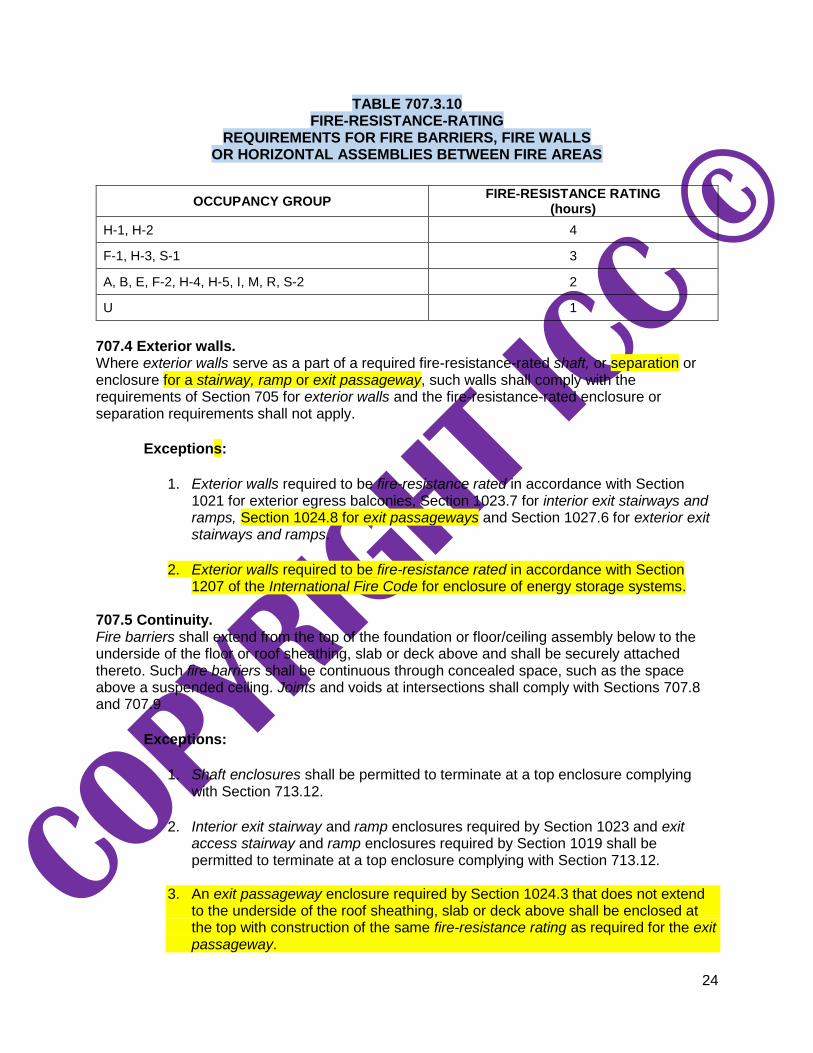
707.3.10 Fire areas. The fire barriers, fire walls, horizontal assemblies or combinations thereof separating a single occupancy into different fire areas shall have a fire-resistance rating of not less than that indicated in Table 707.3.10. The fire barriers, fire walls, horizontal assemblies or combinations thereof separating fire areas of mixed occupancies shall have a fire-resistance rating of not less than the highest value indicated in Table 707.3.10 for the occupancies under consideration.
24
TABLE 707.3.10 FIRE-RESISTANCE-RATING
REQUIREMENTS FOR FIRE BARRIERS, FIRE WALLS OR HORIZONTAL ASSEMBLIES BETWEEN FIRE AREAS
OCCUPANCY GROUP FIRE-RESISTANCE RATING
(hours)
H-1, H-2 4
F-1, H-3, S-1 3
A, B, E, F-2, H-4, H-5, I, M, R, S-2 2
U 1
707.4 Exterior walls. Where exterior walls serve as a part of a required fire-resistance-rated shaft, or separation or enclosure for a stairway, ramp or exit passageway, such walls shall comply with the requirements of Section 705 for exterior walls and the fire-resistance-rated enclosure or separation requirements shall not apply.
Exceptions:
1. Exterior walls required to be fire-resistance rated in accordance with Section
1021 for exterior egress balconies, Section 1023.7 for interior exit stairways and ramps, Section 1024.8 for exit passageways and Section 1027.6 for exterior exit stairways and ramps.
2. Exterior walls required to be fire-resistance rated in accordance with Section
1207 of the International Fire Code for enclosure of energy storage systems. 707.5 Continuity. Fire barriers shall extend from the top of the foundation or floor/ceiling assembly below to the underside of the floor or roof sheathing, slab or deck above and shall be securely attached thereto. Such fire barriers shall be continuous through concealed space, such as the space above a suspended ceiling. Joints and voids at intersections shall comply with Sections 707.8 and 707.9
Exceptions:
1. Shaft enclosures shall be permitted to terminate at a top enclosure complying
with Section 713.12.
2. Interior exit stairway and ramp enclosures required by Section 1023 and exit
access stairway and ramp enclosures required by Section 1019 shall be permitted to terminate at a top enclosure complying with Section 713.12.
3. An exit passageway enclosure required by Section 1024.3 that does not extend
to the underside of the roof sheathing, slab or deck above shall be enclosed at the top with construction of the same fire-resistance rating as required for the exit passageway.

25
707.5.1 Supporting construction. The supporting construction for a fire barrier shall be protected to afford the required fire-resistance rating of the fire barrier supported. Hollow vertical spaces within a fire barrier shall be fireblocked in accordance with Section 718.2 at every floor level.
Exceptions:
1. The maximum required fire-resistance rating for assemblies supporting fire
barriers separating tank storage as provided for in Section 415.9.1.2 shall be 2 hours, but not less than required by Table 601 for the building construction type.
2. Supporting construction for 1-hour fire barriers required by Table 509.1 in
buildings of Types IIB, IIIB and VB construction is not required to be fire-resistance rated unless required by other sections of this code.
707.6 Openings. Openings in a fire barrier shall be protected in accordance with Section 716. Openings shall be limited to a maximum aggregate width of 25 percent of the length of the wall, and the maximum
area of any single opening shall not exceed 156 square feet (15 m2). Openings in enclosures for
exit access stairways and ramps, interior exit stairways and ramps and exit passageways shall also comply with Sections 1019, 1023.4 and 1024.5, respectively.
Exceptions:
1. Openings shall not be limited to 156 square feet (15 m2) where adjoining floor
areas are equipped throughout with an automatic sprinkler system in accordance with Section 903.3.1.1.
2. Openings shall not be limited to 156 square feet (15 m2) or an aggregate width of
25 percent of the length of the wall where the opening protective is a fire door serving enclosures for exit access stairways and ramps, and interior exit stairways and ramps.
3. Openings shall not be limited to 156 square feet (15 m2) or an aggregate width of
25 percent of the length of the wall where the opening protective has been tested in accordance with ASTM E119 or UL 263 and has a minimum fire-resistance rating not less than the fire-resistance rating of the wall.
4. Fire window assemblies permitted in atrium separation walls shall not be limited
to a maximum aggregate width of 25 percent of the length of the wall.
5. Openings shall not be limited to 156 square feet (15 m2) or an aggregate width of
25 percent of the length of the wall where the opening protective is a fire door assembly in a fire barrier separating an enclosure for exit access stairways and ramps, and interior exit stairways and ramps from an exit passageway in accordance with Section 1023.3.1.

26
707.7 Penetrations. Penetrations of fire barriers shall comply with Section 714.
707.7.1 Prohibited penetrations. Penetrations into enclosures for exit access stairways and ramps, interior exit stairways and ramps, and exit passageways shall be allowed only where permitted by Sections 1019, 1023.5 and 1024.6, respectively.
707.8 Joints. Joints made in or between fire barriers, and joints made at the intersection of fire barriers with underside of a fire-resistance-rated floor or roof sheathing, slab or deck above, and the exterior vertical wall intersection shall comply with Section 715. 707.9 Voids at intersections. The voids created at the intersection of a fire barrier and a nonfire-resistance-rated roof assembly or a nonfire-resistance-rated exterior wall assembly shall be filled. An approved material or system shall be used to fill the void, and shall be securely installed in or on the intersection for its entire length so as not to dislodge, loosen or otherwise impair its ability to accommodate expected building movements and to retard the passage of fire and hot gases. 707.10 Ducts and air transfer openings. Penetrations in a fire barrier by ducts and air transfer openings shall comply with Section 717.
SECTION 708
FIRE PARTITIONS 708.1 General. The following wall assemblies shall comply with this section:
1. Separation walls as required by Section 420.2 for Group I-1 and Group R occupancies.
2. Walls separating tenant spaces in covered and open mall buildings as required by
Section 402.4.2.1.
3. Corridor walls as required by Section 1020.3.
4. Enclosed elevator lobby separation as required by Section 3006.3.
5. Egress balconies as required by Section 1021.2
6. Walls separating ambulatory care facilities from adjacent spaces, corridors or tenant as
required by Section 422.2.
7. Walls separating dwelling and sleeping units in Groups R-1 and R-2 in accordance with
Sections 907.2.8.1 and 907.2.9.1.
8. Vestibules in accordance with Section 1028.2.

27
708.2 Materials. The walls shall be of materials permitted by the building type of construction. 708.3 Fire-resistance rating. Fire partitions shall have a fire-resistance rating of not less than 1 hour.
Exceptions:
1. Corridor walls permitted to have a 1/2-hour fire-resistance rating by Table 1020.2.
2. Dwelling unit and sleeping unit separations in buildings of Types IIB, IIIB and VB
construction shall have fire-resistance ratings of not less than 1/2 hour in buildings
equipped throughout with an automatic sprinkler system in accordance with Section 903.3.1.1.
708.4 Continuity. Fire partitions shall extend from the top of the foundation or floor/ceiling assembly below and be securely attached to one of the following:
1. The underside of the floor or roof sheathing, deck or slab above.
2. The underside of a floor/ceiling or roof/ceiling assembly having a fire-resistance rating
that is not less than the fire-resistance rating of the fire partition.
Exceptions:
1. Fire partitions shall not be required to extend into a crawl space below where the
floor above the crawl space has a minimum 1-hour fire-resistance rating.
2. Fire partitions serving as a corridor wall shall not be required to extend above the
lower membrane of a corridor ceiling provided that the corridor ceiling membrane is equivalent to corridor wall membrane, and either of the following conditions is met:
2.1. The room-side membrane of the corridor wall extends to the underside of
the floor or roof sheathing, deck or slab of a fire-resistance-rated floor or roof above.
2.2. The building is equipped with an automatic sprinkler system installed
throughout in accordance with Section 903.3.1.1 or 903.3.1.2, including automatic sprinklers installed in the space between the top of the fire partition and underside of the floor or roof sheathing, deck or slab above.
3. Fire partitions serving as a corridor wall shall be permitted to terminate at the upper
membrane of the corridor ceiling assembly where the corridor ceiling is constructed as required for the corridor wall.
4. Fire partitions separating tenant spaces in a covered or open mall building complying
with Section 402.4.2.1 shall not be required to extend above the underside of a

28
ceiling. Such ceiling shall not be required to be part of a fire-resistance-rated assembly, and the attic or space above the ceiling at tenant separation walls shall not be required to be subdivided by fire partitions.
708.4.1 Supporting construction. The supporting construction for a fire partition shall have a fire-resistance rating that is equal to or greater than the required fire-resistance rating of the supported fire partition.
Exception: In buildings of Types IIB, IIIB and VB construction, the supporting construction requirement shall not apply to fire partitions separating tenant spaces in covered and open mall buildings, fire partitions separating dwelling units, fire partitions separating sleeping units, fire partitions serving as corridor walls, fire partitions separating ambulatory care facilities from adjacent spaces or corridors, fire partitions separating dwelling and sleeping units from Group R-1 and R-2 occupancies and fire partitions separating vestibules from the level of exit discharge.
708.4.2 Fireblocks and draftstops in combustible construction. In combustible construction where fire partitions do not extend to the underside of the floor or roof sheathing, deck or slab above, the space above and along the line of the fire partition shall be provided with one of the following:
1. Fireblocking up to the underside of the floor or roof sheathing, deck or slab above
using materials complying with Section 718.2.1.
2. Draftstopping up to the underside of the floor or roof sheathing, deck or slab above
using materials complying with Section 718.3.1 for floors or Section 718.4.1 for attics.
Exceptions:
1. Buildings equipped with an automatic sprinkler system installed throughout in
accordance with Section 903.3.1.1, or in accordance with Section 903.3.1.2 provided that protection is provided in the space between the top of the fire partition and underside of the floor or roof sheathing, deck or slab above as required for systems complying with Section 903.3.1.1.
2. Where corridor walls provide a sleeping unit or dwelling unit separation,
draftstopping shall only be required above one of the corridor walls.
3. In Group R-2 occupancies with fewer than four dwelling units, fireblocking and
draftstopping shall not be required.
4. In Group R-2 occupancies up to and including four stories in height in buildings
not exceeding 60 feet (18 288 mm) in height above grade plane, the attic space shall be subdivided by draftstops into areas not exceeding 3,000 square feet
(279 m2) or above every two dwelling units, whichever is smaller.
5. In Group R-3 occupancies with fewer than three dwelling units, fireblocking and
draftstopping shall not be required in floor assemblies.

29
708.5 Exterior walls. Where exterior walls serve as a part of a required fire-resistance-rated separation, such walls shall comply with the requirements of Section 705 for exterior walls, and the fire-resistance-rated separation requirements shall not apply.
Exception: Exterior walls required to be fire-resistance rated in accordance with Section 1021.2 for exterior egress balconies, Section 1023.7 for interior exit stairways and ramps and Section 1027.6 for exterior exit stairways and ramps.
708.6 Openings. Openings in a fire partition shall be protected in accordance with Section 716. 708.7 Penetrations. Penetrations of fire partitions shall comply with Section 714. 708.8 Joints. Joints made in or between fire partitions shall comply with Section 715. 708.9 Ducts and air transfer openings. Penetrations in a fire partition by ducts and air transfer openings shall comply with Section 717.
SECTION 709
SMOKE BARRIERS 709.1 General. Vertical and horizontal smoke barriers shall comply with this section. 709.2 Materials. Smoke barriers shall be of materials permitted by the building type of construction. 709.3 Fire-resistance rating. A 1-hour fire-resistance rating is required for smoke barriers.
Exception: Smoke barriers constructed of minimum 0.10-inch-thick (2.5 mm) steel in Group I-3 buildings.
709.4 Continuity. Smoke barriers shall form an effective membrane continuous from the top of the foundation or floor/ceiling assembly below to the underside of the floor or roof sheathing, deck or slab above, including continuity through concealed spaces, such as those found above suspended ceilings, and interstitial structural and mechanical spaces. The supporting construction shall be protected to afford the required fire-resistance rating of the wall or floor supported in buildings of other than Type IIB, IIIB or VB construction. Smoke-barrier walls used to separate smoke compartments shall comply with Section 709.4.1. Smoke-barrier walls used to enclose areas of refuge in accordance with Section 1009.6.4 or to enclose elevator lobbies in accordance with Section 405.4.3, 3007.6.2, or 3008.6.2 shall comply with Section 709.4.2.
Exception: Smoke-barrier walls are not required in interstitial spaces where such spaces are designed and constructed with ceilings or exterior walls that provide resistance to the passage of fire and smoke equivalent to that provided by the smoke-barrier walls.

30
709.4.1 Smoke-barrier assemblies separating smoke compartments. Smoke-barrier assemblies used to separate smoke compartments shall form an effective membrane enclosure that is continuous from an outside wall or smoke barrier wall to an outside wall or another smoke barrier wall and to the horizontal assemblies.
709.4.2 Smoke-barrier walls enclosing areas of refuge or elevator lobbies. Smoke-barrier walls used to enclose areas of refuge in accordance with Section 1009.6.4, or to enclose elevator lobbies in accordance with Section 405.4.3, 3007.6.2, or 3008.6.2, shall form an effective membrane enclosure that terminates at a fire barrier wall having a level of fire protection rating not less than 1 hour, another smoke barrier wall or an outside wall. A smoke and draft control door assembly as specified in Section 716.2.2.1.1 shall not be required at each elevator hoistway door opening or at each exit doorway between an area of refuge and the exit enclosure.
709.5 Openings. Openings in a smoke barrier shall be protected in accordance with Section 716.
Exceptions:
1. In Group I-1, Condition 2, Group I-2 and ambulatory care facilities, where a pair of
opposite-swinging doors are installed across a corridor in accordance with Section 709.5.1, the doors shall not be required to be protected in accordance with Section 716. The doors shall be close fitting within operational tolerances, and shall not have
a center mullion or undercuts in excess of 3/4 inch (19.1 mm), louvers or grilles. The
doors shall have head and jamb stops, and astragals or rabbets at meeting edges. Where permitted by the door manufacturer’s listing, positive-latching devices are not required. Factory-applied or field-applied protective plates are not required to be labeled.
2. In Group I-1, Condition 2, Group I-2 and ambulatory care facilities, special purpose
horizontal sliding, accordion or folding doors installed in accordance with Section 1010.3.3 and protected in accordance with Section 716.
709.5.1 Group I-2 and ambulatory care facilities. In Group I-2 and ambulatory care facilities, where doors protecting openings in smoke barriers are installed across a corridor and have hold-open devices, the doors shall be automatic-closing in accordance with Section 716.2.6.6. Such doors shall have a vision panel with fire-protection-rated glazing materials in fire-protection-rated frames, the area of which shall not exceed that tested.
709.6 Penetrations. Penetrations of smoke barriers shall comply with Section 714. 709.7 Joints. Joints made in or between smoke barriers shall comply with Section 715.

31
709.8 Ducts and air transfer openings. Penetrations in a smoke barrier by ducts and air transfer openings shall comply with Section 717.
SECTION 710
SMOKE PARTITIONS 710.1 General. Smoke partitions installed as required elsewhere in the code shall comply with this section. 710.2 Materials. The walls shall be of materials permitted by the building type of construction. 710.3 Fire-resistance rating. Unless required elsewhere in the code, smoke partitions are not required to have a fire-resistance rating. 710.4 Continuity. Smoke partitions shall extend from the top of the foundation or floor below to the underside of the floor or roof sheathing, deck or slab above or to the underside of the ceiling above where the ceiling membrane is constructed to limit the transfer of smoke. 710.5 Openings. Openings in smoke partitions shall comply with Sections 710.5.1 through 710.5.3.
710.5.1 Windows. Windows in smoke partitions shall be sealed to resist the free passage of smoke or be automatic-closing upon detection of smoke.
710.5.2 Doors. Doors in smoke partitions shall comply with Sections 710.5.2.1 through 710.5.2.3.
710.5.2.1 Louvers. Doors in smoke partitions shall not include louvers.
Exception: Where permitted in accordance with Section 407.3.1.1.
710.5.2.2 Smoke and draft control doors. Where required elsewhere in the code, doors in smoke partitions shall meet the requirements for a smoke and draft control door assembly tested in accordance with UL 1784. The air leakage rate of the door assembly shall not exceed 3.0 cubic feet per
minute per square foot [0.015424 m3/(s × m
2)] of door opening at 0.10 inch (24.9 Pa) of
water for both the ambient temperature test and the elevated temperature exposure test. Installation of smoke doors shall be in accordance with NFPA 105.
710.5.2.2.1 Smoke and draft control door labeling. Smoke and draft control doors complying only with UL 1784 shall be permitted to show the letter “S” on the manufacturer’s labeling.

32
710.5.2.3 Self- or automatic-closing doors. Where required elsewhere in the code, doors in smoke partitions shall be self- or automatic-closing by smoke detection in accordance with Section 716.2.6.6.
710.5.3 Pass-through openings in Group I-2, Condition 2. Where pass-through openings are provided in smoke partitions in Group I-2, Condition 2
occupancies, such openings shall comply with the following:
1. The smoke compartment in which the passthrough openings occur does not contain a
patient care suite or sleeping room.
2. Pass-through openings are installed in a wall, door or vision panel that is not required
to have a fire-resistance rating.
3. The top of the pass-through opening is located a maximum of 48 inches (1219 mm)
above the floor.
4. The aggregate area of all such pass-through openings within a single room shall not
exceed 80 square inches (0.05 m2). 710.6 Penetrations. The space around penetrating items shall be filled with an approved material to limit the free passage of smoke. 710.7 Joints. Joints shall be filled with an approved material to limit the free passage of smoke. 710.8 Ducts and air transfer openings. The space around a duct penetrating a smoke partition shall be filled with an approved material to limit the free passage of smoke. Air transfer openings in smoke partitions shall be provided with a smoke damper complying with Section 717.3.2.2.
Exception: Where the installation of a smoke damper will interfere with the operation of a required smoke control system in accordance with Section 909, approved alternative protection shall be utilized.
SECTION 711
FLOOR AND ROOF ASSEMBLIES 711.1 General. Horizontal assemblies shall comply with Section 711.2. Nonfire-resistance-rated floor and roof assemblies shall comply with Section 711.3. 711.2 Horizontal assemblies. Horizontal assemblies shall comply with Sections 711.2.1 through 711.2.6.
711.2.1 Materials. Assemblies shall be of materials permitted by the building type of construction.

33
711.2.2 Continuity. Assemblies shall be continuous without vertical openings, except as permitted by this section and Section 712.
711.2.3 Supporting construction. The supporting construction shall be protected to afford the required fire-resistance rating of the horizontal assembly supported.
Exception: In buildings of Type IIB, IIIB or VB construction, the construction supporting the horizontal assembly is not required to be fire-resistance rated at the following:
1. Horizontal assemblies at the separations of incidental uses as specified by Table
509.1 provided that the required fire-resistance rating does not exceed 1 hour.
2. Horizontal assemblies at the separations of dwelling units and sleeping units as
required by Section 420.3.
3. Horizontal assemblies at smoke barriers constructed in accordance with Section
709.
711.2.4 Fire-resistance rating. The fire-resistance rating of horizontal assemblies shall comply with Sections 711.2.4.1 through 711.2.4.6 but shall be not less than that required by the building type of construction.
711.2.4.1 Separating mixed occupancies. Where the horizontal assembly separates mixed occupancies, the assembly shall have a fire-resistance rating of not less than that required by Section 508.4 based on the occupancies being separated.
711.2.4.2 Separating fire areas. Where the horizontal assembly separates a single occupancy into different fire areas, the assembly shall have a fire-resistance rating of not less than that required by Section 707.3.10.
711.2.4.3 Dwelling units and sleeping units. Horizontal assemblies serving as dwelling or sleeping unit separations in accordance with Section 420.3 shall be not less than 1-hour fire-resistance-rated construction.
Exception: Horizontal assemblies separating dwelling units and sleeping units shall
be not less than 1/2-hour fire-resistance-rated construction in a building of Types IIB,
IIIB and VB construction, where the building is equipped throughout with an automatic sprinkler system in accordance with Section 903.3.1.1.
711.2.4.4 Separating smoke compartments. Where the horizontal assembly is required to be a smoke barrier, the assembly shall comply with Section 709.

34
711.2.4.5 Separating incidental uses. Where the horizontal assembly separates incidental uses from the remainder of the building, the assembly shall have a fire-resistance rating of not less than that required by Section 509.
711.2.4.6 Other separations. Where a horizontal assembly is required by other sections of this code, the assembly shall have a fire-resistance rating of not less than that required by that section.
711.2.5 Ceiling panels. Where the weight of lay-in ceiling panels, used as part of fire-resistance-rated floor/ceiling or roof/ceiling assemblies, is not adequate to resist an upward force of 1 pound per square foot (48 Pa), wire or other approved devices shall be installed above the panels to prevent vertical displacement under such upward force.
711.2.6 Unusable space. In 1-hour fire-resistance-rated floor/ceiling assemblies, the ceiling membrane is not required to be installed over unusable crawl spaces. In 1-hour fire-resistance-rated roof assemblies, the floor membrane is not required to be installed where unusable attic space occurs above.
711.3 Nonfire-resistance-rated floor and roof assemblies. Nonfire-resistance-rated floor, floor/ceiling, roof and roof/ceiling assemblies shall comply with Sections 711.3.1 and 711.3.2.
711.3.1 Materials. Assemblies shall be of materials permitted by the building type of construction.
711.3.2 Continuity. Assemblies shall be continuous without vertical openings, except as permitted by Section 712.
SECTION 712
VERTICAL OPENINGS 712.1 General. Each vertical opening shall comply in accordance with one of the protection methods in Sections 712.1.1 through 712.1.16.
712.1.1 Shaft enclosures. Vertical openings contained entirely within a shaft enclosure complying with Section 713 shall be permitted.
712.1.2 Individual dwelling unit. Unconcealed vertical openings totally within an individual residential dwelling unit and connecting four stories or less shall be permitted.
712.1.3 Escalator openings. Where a building is equipped throughout with an automatic sprinkler system in accordance with Section 903.3.1.1, vertical openings for escalators shall be permitted where protected in accordance with Section 712.1.3.1 or 712.1.3.2.

35
712.1.3.1 Opening size. Protection by a draft curtain and closely spaced sprinklers in accordance with NFPA 13 shall be permitted where the area of the vertical opening between stories does not exceed twice the horizontal projected area of the escalator. In other than Groups B and M, this application is limited to openings that do not connect more than four stories.
712.1.3.2 Automatic shutters. Protection of the vertical opening by approved shutters at every penetrated floor shall be permitted in accordance with this section. The shutters shall be of noncombustible construction and have a fire-resistance rating of not less than 1.5 hours. The shutter shall be so constructed as to close immediately upon the actuation of a smoke detector installed in accordance with Section 907.3.1 and shall completely shut off the well opening. Escalators shall cease operation when the shutter begins to close. The shutter shall operate at a speed of not more than 30 feet per minute (152.4 mm/s) and shall be equipped with a sensitive leading edge to arrest its progress where in contact with any obstacle, and to continue its progress on release therefrom.
712.1.4 Penetrations. Penetrations, concealed and unconcealed, shall be permitted where protected in accordance with Section 714.
712.1.5 Joints. Joints shall be permitted where complying with Section 712.1.5.1 or 712.1.5.2, as applicable.
712.1.5.1 Joints in or between horizontal assemblies. Joints made in or between horizontal assemblies shall comply with Section 715. The void created at the intersection of a floor/ceiling assembly and an exterior curtain wall assembly shall be permitted where protected in accordance with Section 715.4.
712.1.5.2 Joints in or between nonfire-resistance-rated floor assemblies. Joints in or between floor assemblies without a required fire-resistance rating shall be permitted where they comply with one of the following:
1. The joint shall be concealed within the cavity of a wall.
2. The joint shall be located above a ceiling.
3. The joint shall be sealed, treated or covered with an approved material or system
to resist the free passage of flame and the products of combustion.
Exception: Joints meeting one of the exceptions specified in Section 715.3.

36
712.1.6 Ducts and air transfer openings. Penetrations by ducts and air transfer openings shall be protected in accordance with Section 717. Grease ducts shall be protected in accordance with the International Mechanical Code.
712.1.7 Atriums. Atriums complying with Section 404 that connect two or more stories in Group I-2 or I-3
occupancies or three or more stories in other occupancies shall be permitted.
Exceptions:
1. Atriums shall not be permitted within Group H occupancies.
2. Balconies or stories within Groups A-1, A-4 and A-5 and mezzanines that comply
with Section 505 shall not be considered a story as it applies to this section.
712.1.8 Masonry chimney. Approved vertical openings for masonry chimneys shall be permitted where the annular space is fireblocked at each floor level in accordance with Section 718.2.5.
712.1.9 Two-story openings. In other than Groups I-2 and I-3, a vertical opening that is not used as one of the applications specified in this section shall be permitted if the opening complies with all of the following items:
1. Does not connect more than two stories.
2. Does not penetrate a horizontal assembly that separates fire areas or smoke barriers
that separate smoke compartments.
3. Is not concealed within the construction of a wall or a floor/ceiling assembly.
4. Is not open to a corridor in Group I and R occupancies.
5. Is not open to a corridor on nonsprinklered floors.
6. Is separated from floor openings and air transfer openings serving other floors by
construction conforming to required shaft enclosures.
712.1.10 Parking garages. Vertical openings in parking garages for automobile ramps, elevators and duct systems shall comply with Section 712.1.10.1, 712.1.10.2 or 712.1.10.3, as applicable.
712.1.10.1 Automobile ramps. Vertical openings for automobile ramps in parking garages shall be permitted where constructed in accordance with Sections 406.5 and 406.6.
712.1.10.2 Elevators. Vertical openings for elevator hoistways in parking garages that serve only the parking garage, and complying with Sections 406.5 and 406.6, respectively, shall be permitted.

37
712.1.10.3 Duct systems. Vertical openings for mechanical exhaust or supply duct systems in parking garages complying with Sections 406.5 and 406.6, respectively, shall be permitted to be unenclosed where such duct system is contained within and serves only the parking garage.
712.1.11 Mezzanine. Vertical openings between a mezzanine complying with Section 505 and the floor below shall be permitted.
712.1.12 Exit access stairways and ramps. Vertical openings containing exit access stairways or ramps in accordance with Section 1019 shall be permitted.
712.1.13 Openings. Vertical openings for floor fire doors and access doors shall be permitted where protected by Section 712.1.13.1 or 712.1.13.2.
712.1.13.1 Horizontal fire door assemblies. Horizontal fire door assemblies used to protect openings in fire-resistance-rated horizontal assemblies shall be tested in accordance with NFPA 288, and shall achieve a fire-resistance rating not less than the assembly being penetrated. Horizontal fire door assemblies shall be labeled by an approved agency. The label shall be permanently affixed and shall specify the manufacturer, the test standard and the fire-resistance rating.
712.1.13.2 Access doors. Access doors shall be permitted in ceilings of fire-resistance-rated floor/ceiling and roof/ceiling assemblies, provided that such doors are tested in accordance with ASTM E119 or UL 263 as horizontal assemblies and labeled by an approved agency for such purpose.
712.1.14 Group I-3. In Group I-3 occupancies, vertical openings shall be permitted in accordance with Section 408.5.
712.1.15 Skylights. Skylights and other penetrations through a fire-resistance-rated roof deck or slab are permitted to be unprotected, provided that the structural integrity of the fire-resistance-rated roof assembly is maintained. Unprotected skylights shall not be permitted in roof assemblies required to be fire-resistance rated in accordance with Section 705.8.6. The supporting construction shall be protected to afford the required fire-resistance rating of the horizontal assembly supported.
712.1.16 Openings otherwise permitted. Vertical openings shall be permitted where allowed by other sections of this code.
38
SECTION 713 SHAFT ENCLOSURES
713.1 General. The provisions of this section shall apply to shafts required to protect openings and penetrations through floor/ceiling and roof/ceiling assemblies. Interior exit stairways and ramps shall be enclosed in accordance with Section 1023. 713.2 Construction. Shaft enclosures shall be constructed as fire barriers in accordance with Section 707 or horizontal assemblies in accordance with Section 711, or both. 713.3 Materials. Shaft enclosures shall be of materials permitted by the building type of construction. 713.4 Fire-resistance rating. Shaft enclosures shall have a fire-resistance rating of not less than 2 hours where connecting four stories or more, and not less than 1 hour where connecting less than four stories. The number of stories connected by the shaft enclosure shall include any basements but not any mezzanines. Shaft enclosures shall have a fire-resistance rating not less than the floor assembly penetrated, but need not exceed 2 hours. Shaft enclosures shall meet the requirements of Section 703.2.1.1. 713.5 Continuity. Shaft enclosures shall be constructed as fire barriers in accordance with Section 707 or horizontal assemblies constructed in accordance with Section 711, or both, and shall have continuity in accordance with Section 707.5 for fire barriers or Section 711.2.2 for horizontal assemblies, as applicable. 713.6 Exterior walls. Where exterior walls serve as a part of a required shaft enclosure, such walls shall comply with the requirements of Section 705 for exterior walls and the fire-resistance-rated enclosure requirements shall not apply.
Exception: Exterior walls required to be fire-resistance rated in accordance with Section 1021.2 for exterior egress balconies, Section 1023.7 for interior exit stairways and ramps and Section 1027.6 for exterior exit stairways and ramps.
713.7 Openings. Openings in a shaft enclosure shall be protected in accordance with Section 716 as required for fire barriers. Doors shall be self- or automatic-closing by smoke detection in accordance with Section 716.2.6.6.
713.7.1 Prohibited openings. Openings other than those necessary for the purpose of the shaft shall not be permitted in shaft enclosures.
39
713.8 Penetrations. Penetrations in a shaft enclosure shall be protected in accordance with Section 714 as required for fire barriers. Structural elements, such as beams or joists, where protected in accordance with Section 714 shall be permitted to penetrate a shaft enclosure.
713.8.1 Prohibited penetrations. Penetrations other than those necessary for the purpose of the shaft shall not be permitted in shaft enclosures.
Exception: Membrane penetrations shall be permitted on the outside of shaft enclosures. Such penetrations shall be protected in accordance with Section 714.4.2.
713.9 Joints. Joints in a shaft enclosure shall comply with Section 715. 713.10 Duct and air transfer openings. Penetrations of a shaft enclosure by ducts and air transfer openings shall comply with Section 717. 713.11 Enclosure at the bottom. Shafts that do not extend to the bottom of the building or structure shall comply with one of the following:
1. Be enclosed at the lowest level with construction of the same fire-resistance rating as
the lowest floor through which the shaft passes, but not less than the rating required for the shaft enclosure.
2. Terminate in a room having a use related to the purpose of the shaft. The room shall be
separated from the remainder of the building by fire barriers constructed in accordance with Section 707 or horizontal assemblies constructed in accordance with Section 711, or both. The fire-resistance rating and opening protectives shall be not less than the protection required for the shaft enclosure.
3. Be protected by approved fire dampers installed in accordance with their listing at the
lowest floor level within the shaft enclosure.
Exceptions:
1. The fire-resistance-rated room separation is not required, provided that the only
openings in or penetrations of the shaft enclosure to the interior of the building occur at the bottom. The bottom of the shaft shall be closed off around the penetrating items with materials permitted by Section 718.3.1 for draftstopping, or the room shall be provided with an approved automatic sprinkler system.
2. A shaft enclosure containing a waste or linen chute shall not be used for any other
purpose and shall discharge in a room protected in accordance with Section 713.13.4.

40
3. The fire-resistance-rated room separation and the protection at the bottom of the shaft are not required provided that there are no combustibles in the shaft and there are no openings or other penetrations through the shaft enclosure to the interior of the building.
713.12 Enclosure at top.
The top of shaft enclosures shall comply with one of the following:
1. Extend to the underside of the roof sheathing, deck or slab of the building, and the roof
assembly shall comply with the requirements for the type of construction as specified in Table 601.
2. Terminate below the roof assembly and be enclosed at the top with construction of the
same fire-resistance rating as the topmost floor penetrated by the shaft, but not less than the fire-resistance rating required for the shaft enclosure.
3. Extend past the roof assembly and comply with the requirements of Section 1511.
713.12.1 Penthouse mechanical rooms. A fire/smoke damper shall not be required at the penetration of the rooftop structure where shaft enclosures extend up through the roof assembly into a rooftop structure conforming to
Section 1511. Ductwork in the shaft shall be connected directly to HVAC equipment.
713.13 Waste, recycling and linen chutes and incinerator rooms. Waste, recycling and linen chutes shall comply with the provisions of NFPA 82, Chapter 6 and shall meet the requirements of Sections 712 and 713.13.1 through 713.13.6. Incinerator rooms shall meet the provisions of Sections 713.13.4 and 713.13.5.
Exception: Chutes serving and contained within a single dwelling unit.
713.13.1 Waste, recycling and linen chute enclosures. A shaft enclosure containing a recycling, waste or linen chute shall not be used for any other purpose and shall be enclosed in accordance with Section 713.4. A shaft enclosure shall be permitted to contain recycling and waste chutes. Openings into the shaft, from access rooms and discharge rooms, shall be protected in accordance with this section and Section 716. Openings into chutes shall not be located in corridors. Doors into chutes shall be self-closing. Discharge doors shall be self-or automatic-closing upon the actuation of a smoke detector in accordance with Section 716.2.6.6, except that heat-activated closing devices shall be permitted between the shaft and the discharge room.
713.13.2 Materials. A shaft enclosure containing a waste, recycling, or linen chute shall be constructed of materials as permitted by the building type of construction.
713.13.3 Chute access rooms.
Access openings for waste, recycling or linen chutes shall be located in rooms or
compartments enclosed by not less than 1-hour fire barriers constructed in accordance with Section 707 or horizontal assemblies constructed in accordance with Section 711, or both. Openings into the access rooms shall be protected by opening protectives having a fire

41
protection rating of not less than 3/4 hour. Doors shall be self- or automatic-closing upon the
detection of smoke in accordance with Section 716.2.6.6. The room or compartment shall be configured to allow the access door to the room or compartment to close and latch with the access panel to the chute in any position.
713.13.4 Chute discharge room. Table 509.1Waste, recycling or linen chutes shall discharge into an enclosed room separated by fire barriers with a fire-resistance rating not less than the required fire rating of the shaft enclosure and constructed in accordance with Section 707 or horizontal assemblies constructed in accordance with Section 711, or both. Openings into the discharge room from the remainder of the building shall be protected by opening protectives having a fire protection rating equal to the protection required for the shaft enclosure. Doors shall be self- or automatic-closing upon the detection of smoke in accordance with Section 716.2.6.6. Waste chutes shall not terminate in an incinerator room. Waste and linen rooms that are not provided with chutes need only comply with Table 509.1.
713.13.5 Incinerator room. Incinerator rooms shall comply with Table 509.1.
713.13.6 Automatic sprinkler system. An approved automatic sprinkler system shall be installed in accordance with Section 903.2.11.2.
713.14 Elevator, dumbwaiter and other hoistways. Elevator, dumbwaiter and other hoistway enclosures shall be constructed in accordance with Sections 712 and 713, and Chapter 30.
SECTION 714
PENETRATIONS 714.1 Scope. The provisions of this section shall govern the materials and methods of construction used to protect through penetrations and membrane penetrations of horizontal assemblies and fire-resistance-rated wall assemblies.
714.1.1 Ducts and air transfer openings. Penetrations of fire-resistance-rated walls by ducts that are not protected with dampers shall comply with Sections 714.3 through 714.4.3. Penetrations of horizontal assemblies not protected with a shaft as permitted by Section 717.6, and not required to be protected with fire dampers by other sections of this code, shall comply with Sections 714.5 through 714.6.2. Ducts and air transfer openings that are protected with dampers shall comply with Section 717.
714.2 Installation. A listed penetration firestop system shall be installed in accordance with the manufacturer’s installation instructions and the listing criteria.

42
714.3 Installation details. Where sleeves are used, they shall be securely fastened to the assembly penetrated. The space between the item contained in the sleeve and the sleeve itself and any space between the sleeve and the assembly penetrated shall be protected in accordance with this section. Insulation and coverings on or in the penetrating item shall not penetrate the assembly unless the specific material used has been tested as part of the assembly in accordance with this section. 714.4 Fire-resistance-rated walls. Penetrations into or through fire walls, fire barriers, smoke barrier walls and fire partitions shall comply with Sections 714.4.1 through 714.4.3. Penetrations in smoke barrier walls shall also comply with Section 714.5.4.
714.4.1 Through penetrations. Through penetrations of fire-resistance-rated walls shall comply with Section 714.4.1.1 or 714.4.1.2.
Exception: Where the penetrating items are steel, ferrous or copper pipes, tubes or conduits, the annular space between the penetrating item and the fire-resistance-rated wall is permitted to be protected by either of the following measures:
1. In concrete or masonry walls where the penetrating item is a maximum 6-inch
(152 mm) nominal diameter and the area of the opening through the wall does
not exceed 144 square inches (0.0929 m2), concrete, grout or mortar is permitted
where installed the full thickness of the wall or the thickness required to maintain the fire-resistance rating.
2. The material used to fill the annular space shall prevent the passage of flame
and hot gases sufficient to ignite cotton waste when subjected to ASTM E119 or UL 263 time-temperature fire conditions under a minimum positive pressure differential of 0.01 inch (2.49 Pa) of water at the location of the penetration for the time period equivalent to the fire-resistance rating of the construction penetrated.
714.4.1.1 Fire-resistance-rated assemblies. Through penetrations shall be protected using systems installed as tested in the approved fire-resistance-rated assembly.
714.4.1.2 Through-penetration firestop system. Through penetrations shall be protected by an approved penetration firestop system installed as tested in accordance with ASTM E814 or UL 1479, with a minimum positive pressure differential of 0.01 inch (2.49 Pa) of water and shall have an F rating of not less than the required fire-resistance rating of the wall penetrated.
714.4.2 Membrane penetrations. Membrane penetrations shall comply with Section 714.4.1. Where walls or partitions are required to have a fire-resistance rating, recessed fixtures shall be installed such that the required fire resistance will not be reduced.
Exceptions:

43
1. Membrane penetrations of maximum 2-hour fire-resistance-rated walls and partitions by steel electrical boxes that do not exceed 16 square inches (0.0 103
m2) in area, provided that the aggregate area of the openings through the
membrane does not exceed 100 square inches (0.0645 m2) in any 100 square
feet (9.29 m2) of wall area. The annular space between the wall membrane and
the box shall not exceed 1/8 inch (3.2 mm). Such boxes on opposite sides of the
wall or partition shall be separated by one of the following:
1.1. By a horizontal distance of not less than 24 inches (610 mm) where the
wall or partition is constructed with individual noncommunicating stud cavities.
1.2. By a horizontal distance of not less than the depth of the wall cavity
where the wall cavity is filled with cellulose loose-fill, rockwool or slag mineral wool insulation.
1.3. By solid fireblocking in accordance with Section 718.2.1.
1.4. By protecting both outlet boxes with listed putty pads.
1.5. By other listed materials and methods.
2. Membrane penetrations by listed electrical boxes of any material, provided that
such boxes have been tested for use in fire-resistance-rated assemblies and are installed in accordance with the instructions included in the listing. The annular
space between the wall membrane and the box shall not exceed 1/8 inch (3.2
mm) unless listed otherwise. Such boxes on opposite sides of the wall or partition shall be separated by one of the following:
2.1. By the horizontal distance specified in the listing of the electrical boxes.
2.2. By solid fireblocking in accordance with Section 718.2.1.
2.3. By protecting both boxes with listed putty pads.
2.4. By other listed materials and methods.
3. Membrane penetrations by electrical boxes of any size or type, that have been
listed as part of a wall opening protective material system for use in fire-resistance-rated assemblies and are installed in accordance with the instructions included in the listing.
4. Membrane penetrations by boxes other than electrical boxes, provided that such
penetrating items and the annular space between the wall membrane and the box, are protected by an approved membrane penetration firestop system installed as tested in accordance with ASTM E814 or UL 1479, with a minimum

44
positive pressure differential of 0.01 inch (2.49 Pa) of water, and shall have an F and T rating of not less than the required fire-resistance rating of the wall penetrated and be installed in accordance with their listing.
5. The annular space created by the penetration of an automatic sprinkler, provided
that it is covered by a metal escutcheon plate.
6. Membrane penetrations of maximum 2-hour fire-resistance-rated walls and
partitions by steel electrical boxes that exceed 16 square inches (0.0 103 m2) in
area, or steel electrical boxes of any size having an aggregate area through the
membrane exceeding 100 square inches (0.0645 m2) in any 100 square feet
(9.29 m2) of wall area, provided that such penetrating items are protected by
listed putty pads or other listed materials and methods, and installed in accordance with the listing.
714.4.3 Dissimilar materials. Noncombustible penetrating items shall not connect to combustible items beyond the point of firestopping unless it can be demonstrated that the fire-resistance integrity of the wall is maintained.
714.5 Horizontal assemblies. Penetrations of a fire-resistance-rated floor, floor/ceiling assembly or the ceiling membrane of a roof/ceiling assembly not required to be enclosed in a shaft by Section 712.1 shall be protected in accordance with Sections 714.5.1 through 714.5.4.
714.5.1 Through penetrations. Through penetrations of horizontal assemblies shall comply with Section 714.5.1.1 or 714.5.1.2.
Exceptions:
1. Penetrations by steel, ferrous or copper conduits, pipes, tubes or vents or
concrete or masonry items through a single fire-resistance-rated floor assembly where the annular space is protected with materials that prevent the passage of flame and hot gases sufficient to ignite cotton waste when subjected to ASTM E119 or UL 263 time-temperature fire conditions under a minimum positive pressure differential of 0.01 inch (2.49 Pa) of water at the location of the penetration for the time period equivalent to the fire-resistance rating of the construction penetrated. Penetrating items with a maximum 6-inch (152 mm) nominal diameter shall not be limited to the penetration of a single fire-resistance-rated floor assembly, provided that the aggregate area of the openings through the assembly does not exceed 144 square inches (92 900
mm2) in any 100 square feet (9.3 m
2) of floor area.
2. Penetrations in a single concrete floor by steel, ferrous or copper conduits, pipes,
tubes or vents with a maximum 6-inch (152 mm) nominal diameter, provided that the concrete, grout or mortar is installed the full thickness of the floor or the thickness required to maintain the fire-resistance rating. The penetrating items shall not be limited to the penetration of a single concrete floor, provided that the

45
area of the opening through each floor does not exceed 144 square inches (92
900 mm2).
3. Penetrations by listed electrical boxes of any material, provided that such boxes
have been tested for use in fire-resistance-rated assemblies and installed in accordance with the instructions included in the listing.
714.5.1.1 Fire-resistance-rated assemblies. Through penetrations shall be protected using systems installed as tested in the approved fire-resistance-rated assembly.
714.5.1.2 Through-penetration firestop system. Through penetrations shall be protected by an approved through-penetration firestop system installed and tested in accordance with ASTM E814 or UL 1479, with a minimum positive pressure differential of 0.01 inch of water (2.49 Pa). The system shall have an F rating/T rating of not less than 1 hour but not less than the required rating of the floor penetrated.
Exceptions:
1. Floor penetrations contained and located within the cavity of a wall above the
floor or below the floor do not require a T rating.
2. Floor penetrations by floor drains, tub drains or shower drains contained and
located within the concealed space of a horizontal assembly do not require a T rating.
3. Floor penetrations of maximum 4-inch (102 mm) nominal diameter metal
conduit or tubing penetrating directly into metal-enclosed electrical power switchgear do not require a T rating.
714.5.2 Membrane penetrations. Penetrations of membranes that are part of a horizontal assembly shall comply with Section 714.5.1.1 or 714.5.1.2. Where floor/ceiling assemblies are required to have a fire-resistance rating, recessed fixtures shall be installed such that the required fire resistance will not be reduced.
Exceptions:
1. Membrane penetrations by steel, ferrous or copper conduits, pipes, tubes or
vents, or concrete or masonry items where the annular space is protected either in accordance with Section 714.5.1 or to prevent the free passage of flame and the products of combustion. The aggregate area of the openings through the
membrane shall not exceed 100 square inches (64 500 mm2) in any 100 square
feet (9.3 m2) of ceiling area in assemblies tested without penetrations.
2. Ceiling membrane penetrations of maximum 2-hour horizontal assemblies by
steel electrical boxes that do not exceed 16 square inches (10 323 mm2) in area,

46
provided that the aggregate area of such penetrations does not exceed 100
square inches (44 500 mm2) in any 100 square feet (9.29 m
2) of ceiling area, and
the annular space between the ceiling membrane and the box does not exceed 1/8 inch (3.2 mm).
3. Membrane penetrations by electrical boxes of any size or type, that have been
listed as part of an opening protective material system for use in horizontal assemblies and are installed in accordance with the instructions included in the listing.
4. Membrane penetrations by listed electrical boxes of any material, provided that
such boxes have been tested for use in fire-resistance-rated assemblies and are installed in accordance with the instructions included in the listing. The annular
space between the ceiling membrane and the box shall not exceed 1/8 inch (3.2
mm) unless listed otherwise.
5. The annular space created by the penetration of a fire sprinkler, provided that it is
covered by a metal escutcheon plate.
6. Noncombustible items that are cast into concrete building elements and that do
not penetrate both top and bottom surfaces of the element.
7. The ceiling membrane of a maximum 2-hour fire-resistance-rated horizontal
assembly is permitted to be interrupted with the double wood top plate of a wall assembly that is sheathed with Type X gypsum wallboard, provided that all penetrating items through the double top plates are protected in accordance with Section 714.5.1.1 or 714.5.1.2 and the ceiling membrane is tight to the top plates.
8. Ceiling membrane penetrations by listed luminaires (light fixtures) or by
luminaires protected with listed materials, which have been tested for use in fire-resistance-rated assemblies and are installed in accordance with the instructions included in the listing.
714.5.3 Dissimilar materials. Noncombustible penetrating items shall not connect to combustible materials beyond the point of firestopping unless it can be demonstrated that the fire-resistance integrity of the horizontal assembly is maintained.
714.5.4 Penetrations in smoke barriers. Penetrations in smoke barriers shall be protected by an approved through-penetration firestop system installed and tested in accordance with the requirements of UL 1479 for air leakage. The L rating of the system measured at 0.30 inch (7.47 Pa) of water in both the ambient temperature and elevated temperature tests shall not exceed either of the following:
1. 5.0 cfm per square foot (0.025 m3/ s × m
2) of penetration opening for each through-
penetration firestop system.

47
2. A total cumulative leakage of 50 cfm (0.024 m3/s) for any 100 square feet (9.3 m
2) of
wall area, or floor area. 714.6 Nonfire-resistance-rated assemblies. Penetrations of nonfire-resistance-rated floor or floor/ceiling assemblies or the ceiling membrane of a nonfire-resistance-rated roof/ceiling assembly shall meet the requirements of Section 713 or shall comply with Section 714.6.1 or 714.6.2.
714.6.1 Noncombustible penetrating items. Noncombustible penetrating items that connect not more than five stories are permitted, provided that the annular space is filled to resist the free passage of flame and the products of combustion with an approved noncombustible material or with a fill, void or cavity material that is tested and classified for use in through-penetration firestop systems.
714.6.2 Penetrating items. Penetrating items that connect not more than two stories are permitted, provided that the annular space is filled with an approved material to resist the free passage of flame and the products of combustion.
SECTION 715
JOINTS AND VOIDS 715.1 General. The provisions of this section shall govern the materials and methods of construction used to protect joints and voids in or between horizontal and vertical assemblies. 715.2 Installation. Systems or materials protecting joints and voids shall be securely installed in accordance with the manufacturer’s installation instructions in or on the joint or void for its entire length so as not to dislodge, loosen or otherwise impair its ability to accommodate expected building movements and to resist the passage of fire and hot gases. Fire-resistant joint systems or systems used to protect voids at exterior curtain walls and fire-resistance-rated floor intersections shall also be installed in accordance with the listing criteria. 715.3 Fire-resistance-rated assembly intersections. Joints installed in or between fire-resistance-rated walls, floor or floor/ceiling assemblies and roofs or roof/ceiling assemblies shall be protected by an approved fire-resistant joint system designed to resist the passage of fire for a time period not less than the required fire-resistance rating of the wall, floor or roof in or between which the system is installed.
Exception: Fire-resistant joint systems shall not be required for joints in the following locations:
1. Floors within a single dwelling unit.
2. Floors where the joint is protected by a shaft enclosure in accordance with Section
713.

48
3. Floors within atriums where the space adjacent to the atrium is included in the volume of the atrium for smoke control purposes.
4. Floors within malls.
5. Floors and ramps within parking garages or structures constructed in accordance
with Sections 406.5 and 406.6.
6. Mezzanine floors.
7. Walls that are permitted to have unprotected openings.
8. Roofs where openings are permitted.
9. Control joints not exceeding a maximum width of 0.625 inch (15.9 mm) and tested in
accordance with ASTM E119 or UL 263.
10. The intersection of exterior curtain wall assemblies and the roof slab or roof deck.
715.3.1 Fire test criteria. Fire-resistant joint systems shall be tested in accordance with the requirements of either ASTM E1966 or UL 2079. Nonsymmetrical wall joint systems shall be tested with both faces exposed to the furnace, and the assigned fire-resistance rating shall be the shortest duration obtained from the two tests. Where evidence is furnished to show that the wall was tested with the least fire-resistant side exposed to the furnace, subject to acceptance of the building official, the wall need not be subjected to tests from the opposite side.
Exception: For exterior walls with a horizontal fire separation distance greater than 10 feet (3048 mm), the joint system shall be required to be tested for interior fire exposure
only.
715.4 Exterior curtain wall/fire-resistance-rated floor intersections. Voids created at the intersection of exterior curtain wall assemblies and fire-resistance-rated floor or floor/ceiling assemblies shall be protected with an approved perimeter fire containment system to prevent the interior spread of fire. Such systems shall provide an F rating for a time period not less than the fire-resistance rating of the floor or floor/ceiling assembly.
715.4.1 Fire test criteria. Perimeter fire containment systems shall be tested in accordance with the requirements of
ASTM E2307.
Exception: Voids created at the intersection of the exterior curtain wall assemblies and floor assemblies where the vision glass extends to the finished floor level shall be permitted to be protected with an approved material to prevent the interior spread of fire. Such material shall be securely installed and capable of preventing the passage of flame and hot gases sufficient to ignite cotton waste where subjected to ASTM E119 time-temperature fire conditions under a minimum positive pressure differential of 0.01 inch (0.254 mm) of water column (2.5 Pa) for the time period not less than the fire-resistance
rating of the floor assembly.

49
715.5 Exterior curtain wall/nonfire-resistance-rated floor assembly intersections. Voids created at the intersection of exterior curtain wall assemblies and nonfire-resistance-rated floor or floor/ceiling assemblies shall be filled with an approved material or system to retard the interior spread of fire and hot gases between stories. 715.6 Exterior curtain wall/vertical fire barrier intersections. Voids created at the intersection of nonfire-resistance-rated exterior curtain wall assemblies and vertical fire barriers shall be filled with an approved material or system to retard the interior spread of fire and hot gases.
715.7 Curtain wall spandrels. Height and fire-resistance requirements for curtain wall spandrels shall comply with Section 705.8.5. Where Section 705.8.5 does not require fire-resistance-rated curtain wall spandrels, the requirements of Sections 715.4 and 715.5 shall still apply to the intersection between the
curtain wall spandrels and the floor.
715.8 Joints and voids in smoke barriers. Fire-resistant joint systems protecting joints in smoke barriers, and perimeter fire containment systems protecting voids at the intersection of a horizontal smoke barrier and an exterior curtain wall, shall be tested in accordance with the requirements of UL 2079 for air leakage. The L
rating of the joint system shall not exceed 5 cubic feet per minute per linear foot (0.00775 m3/s
m) of joint at 0.30 inch (74.7 Pa) of water for both the ambient temperature and elevated temperature tests.
SECTION 716
OPENING PROTECTIVES
716.1 General. Opening protectives required by other sections of this code shall comply with the provisions of this section and shall be installed in accordance with NFPA 80.
TABLE 716.1(1) MARKING FIRE-RATED GLAZING ASSEMBLIES
FIRE TEST STANDARD
MARKING DEFINITION OF MARKING
ASTM E119 or UL 263 W Meets wall assembly criteria.
ASTM E119 or UL 263 FC Meets floor/ceiling criteriaa
NFPA 257 or UL 9 OH Meets fire window assembly criteria including the hose stream test.
NFPA 252 or UL 10B or UL 10C
D Meets fire door assembly criteria.
H Meets fire door assembly hose stream test.
T Meets 450ºF temperature rise criteria for 30 minutes
— XXX The time in minutes of the fire resistance or fire protection rating of the glazing assembly.
For SI: ºC = [(ºF) – 32]/1.8.
a. See Section 2409.1

50
TABLE 716.1(2) OPENING FIRE PROTECTION ASSEMBLIES, RATINGS AND MARKINGS
TYPE OF ASSEMBLY
REQUIRED WALL
ASSEMBLY RATING (hours)
MINIMUM FIRE DOOR AND FIRE SHUTTER
ASSEMBLY RATING (hours)
DOOR VISION PANEL SIZEa
FIRE-RATED
GLAZING MARKING
DOOR VISION PANELb,c
MINIMUM SIDELIGHT/ TRANSOM ASSEMBLY
RATING (hours)
FIRE-RATED GLAZING MARKING SIDE-
LIGHT/TRANSOM PANEL
Fire protection
Fire resistance
Fire protection
Fire resistance
Fire walls and fire barriers having a required fire-resis- tance rating greater than 1 hour
4 3 See
Note a D-H-W-240
Not Permitted
4 Not
Permitted W-240
3 3d See Note a
D-H-W-180 Not
Permitted 3
Not Permitted
W-180
2
11/
2
100 sq. in.
≤100 sq. in. = D-H-90
>100 sq. in.=D-H-W-
90
Not Permitted
2
Not Permitted
W-120
11/ 2
11/ 2
100 sq. in.
≤100 sq. in. = D-H-90
>100 sq. in.= D-H-W-90
Not
Permitted
11/ 2
Not
Permitted
W-90
Double fire walls constructed in accor- dance with NFPA 221
Single-wall assembly
rating (hours)e
Each wall of the
double- wall
assembly (hours)f
—
4 3 3 See
Note a D-H-W-180
Not Permitted
3 Not
Permitted W-180
3
2
11/ 2
100 sq. in.
≤ 100 sq. in. = D-H-90
>100 sq. in.= D-H-W-90
Not
Permitted
2
Not
Permitted
W-120
2
1
1
100 sq. in.
≤ 100 sq. in. = D-H-60
> 100 sq. in. = D-H-W-60
Not
Permitted
1
Not
Permitted
W-60
Enclosures for shafts, interior exit stairways and inte- rior exit ramps.
2
11/ 2
100 sq. in.b
≤100 sq. in. = D-H-90
> 100 sq. in.= D-H-T-W-90
Not
Permitted
2
Not
Permitted
W-120
(continued)

51
TABLE 716.1(2)—continued OPENING FIRE PROTECTION ASSEMBLIES, RATINGS AND MARKINGS
TYPE OF ASSEMBLY
REQUIRED WALL
ASSEMBLY RATING (hours)
MINIMUM FIRE DOOR AND FIRE SHUTTER
ASSEMBLY RATING (hours)
DOOR VISION PANEL SIZEa
FIRE-RATED
GLAZING MARKING
DOOR VISION PANELb,c
MINIMUM SIDELIGHT/ TRANSOM ASSEMBLY
RATING (hours)
FIRE-RATED GLAZING MARKING SIDE-
LIGHT/TRANSOM PANEL
Fire protection
Fire resistance
Fire protection
Fire resistance
Horizontal exits in fire wallsg
4
3
100 sq. in.
≤100 sq. in. = D-H-180
> 100 sq. in.=D-H-W-
240
Not Permitted
4
Not Permitted
W-240
3
3d
100 sq. in.
≤100 sq. in. = D-H-180
> 100 sq. in.=D-H-W-
180
Not Permitted
3
Not Permitted
W-180
Fire barriers having a required fire-resis- tance rating of 1 hour: Enclosures for shafts, exit access stairways, exit access ramps, inte- rior exit stairways and interior exit ramps; and exit passageway walls
1
1
100 sq. in.
≤100 sq. in. = D-H-60
>100 sq. in.=D-H-T-
W-60
Not
Permitted
1
Not
Permitted
W-60
Fire protection
Other fire barriers 1 3/ 4
Maximum size tested
D-H
3/ h 4 D-Hh
Fire partitions: Corridor walls
1
1/ a 3
Maximum size tested
D-20
3/ a 4 D-H-OH-45
0.5
1/ a 3
Maximum size tested
D-20 1/ 3 D-H-OH-20
Other fire partitions
1
3/ i 4
Maximum size tested
D-H-45 3/ 4 D-H-45
0.5 1/ 3
Maximum size tested
D-H-20 1/ 3 D-H-20
Exterior walls
3
11/ 2
100 sq. in.a
≤100 sq. in. = D-H-90
> 100 sq. in = D-H-W-90
Not
Permitted
3
Not
Permitted
W-180
2 11/ 2
Maximum size tested
D-H 90 or D- H-W-90
11/ h
2 2
D-H-OH-
90h
W-120
Fire protection
1 3/ 4
Maximum size tested
D-H-45
3/ h 4 D-H-45h
Smoke barriers
Fire protection
1 1/ 3
Maximum size tested
D-20 3/ 4 D-H-OH-45

52
TABLE 716.1(2)—continued OPENING FIRE PROTECTION ASSEMBLIES, RATINGS AND MARKINGS
For SI: 1 square inch = 645.2 mm. a. Fire-resistance-rated glazing tested to ASTM E119 in accordance with Section 716.1.2.3 shall be permitted, in
the maximum size tested.
b. Under the column heading “Fire-rated glazing marking door vision panel,” W refers to the fire-resistance rating of the glazing, not the frame.
c. See Section 716.1.2.2.1 and Table 716.1(1) for additional permitted markings.
d. Two doors, each with a fire protection rating of 11/2 hours, installed on opposite sides of the same opening in a
fire wall, shall be deemed equivalent in fire protection rating to one 3-hour fire door. e. As required in Section 706.4. f. As allowed in Section 4.6 of NFPA 221. g. See Section 716.2.5.1.2. h. Fire-protection-rated glazing is not permitted for fire barriers required by Section 1207 of the International Fire
Code to enclose energy storage systems. Fire-resistance-rated glazing assemblies tested to ASTM E119 or UL
263, as specified in Section 716.1.2.3, shall be permitted. i. Two doors, each with a fire rating of 20 minutes, installed on opposite sides of the same opening in a fire
partition, shall be deemed equivalent in fire protection rating to one 45-minute fire door.
TABLE 716.1(3) FIRE WINDOW ASSEMBLY FIRE PROTECTION RATINGS
TYPE OF WALL ASSEMBLY
REQUIRED WALL
ASSEMBLY RATING (hours)
MINIMUM FIRE WINDOW
ASSEMBLY RATING (hours)
FIRE-RATED GLAZING MARKING
Interior walls
Fire walls All NPa W-XXX
b
Fire barriers >1 NPa W-XXX
b
1 NPa W-XXX
b
Atrium separations (Section 707.3.6),
Incidental use areas (Section 707.3.7),c
Mixed occupancy separations (Section 707.3.9)
1 3/4 OH-45 or W-60
Fire partitions 1 3/4 OH-45 or W-60
0.5 1/3
OH-20 or W-30
Smoke barriers 1 3/4 OH-45 or W-60
Exterior walls
>1 11/2
OH-90 or W-
XXXb
1 3/4 OH-45 or W-60
0.5 1/3 OH-20 or W-30
Party wall All NP Not Applicable
NP = Not Permitted.

53
a. Not permitted except fire-resistance-rated glazing assemblies tested to ASTM E119 or UL 263, as specified in Section 716.1.2.3.
b. XXX = The fire rating duration period in minutes, which shall be equal to the fire-resistance rating required for the wall assembly.
c. Fire-protection-rated glazing is not permitted for fire barriers required by Section 1207 of the International Fire Code to enclose energy storage systems. Fire-resistance-rated glazing assemblies tested to ASTM E119 or UL 263, as specified in Section 716.1.2.3, shall be permitted.
716.1.1 Alternative methods for determining fire protection ratings. The application of any of the alternative methods specified in this section shall be based on the fire exposure and acceptance criteria specified in NFPA 252, NFPA 257, UL 9, UL 10B or UL 10C. The required fire resistance of an opening protective shall be permitted to be established by any of the following methods or procedures:
1. Designs documented in approved sources.
2. Calculations performed in an approved manner.
3. Engineering analysis based on a comparison of opening protective designs having
fire protection ratings as determined by the test procedures set forth in NFPA 252, NFPA 257, UL 9, UL 10B or UL 10C.
4. Alternative protection methods as allowed by Section 104.11.
716.1.2 Glazing. Glazing used in fire door assemblies and fire window assemblies shall comply with this section in addition to the requirements of Sections 716.2 and 716.3, respectively.
716.1.2.1 Safety glazing. Fire-protection-rated glazing and fire-resistance-rated glazing installed in fire door assemblies and fire window assemblies shall comply with the safety glazing requirements of Chapter 24 where applicable.
716.1.2.2 Marking fire-rated glazing assemblies. Fire-rated glazing assemblies shall be marked in accordance with Tables 716.1(1), 716.1(2) and 716.1(3).
716.1.2.2.1 Fire-rated glazing identification. For fire-rated glazing, the label shall bear the identification required in Tables 716.1(1) and 716.1(2). “D” indicates that the glazing is permitted to be used in fire door assemblies and meets the fire protection requirements of NFPA 252, UL 10B or UL 10C. “H” indicates that the glazing meets the hose stream requirements of NFPA 252, UL 10B or UL 10C. “T” indicates that the glazing meets the temperature requirements of Section 716.2.2.3.1. The placeholder “XXX” represents the fire-rating period, in minutes.
716.1.2.2.2 Fire-protection-rated glazing identification. For fire-protection-rated glazing, the label shall bear the following identification required in Tables 716.1(1) and 716.1(3): “OH – XXX.” “OH” indicates that the glazing meets both the fire protection and the hose-stream requirements of NFPA 257 or UL 9 and is permitted to be used in fire window openings. The placeholder “XXX” represents the fire-rating period, in minutes.

54
716.1.2.2.3 Fire-resistance-rated glazing identification. For fire-resistance-rated glazing, the label shall bear the identification required in Section 703.4 and Table 716.1(1).
716.1.2.2.4 Fire-rated glazing that exceeds the code requirements. Fire-rated glazing assemblies marked as complying with hose stream requirements (H) shall be permitted in applications that do not require compliance with hose stream requirements. Fire-rated glazing assemblies marked as complying with temperature rise requirements (T) shall be permitted in applications that do not require compliance with temperature rise requirements. Fire-rated glazing assemblies marked with ratings (XXX) that exceed the ratings required by this code shall be permitted.
716.1.2.3 Fire-resistance-rated glazing. Fire-resistance-rated glazing tested as part of a fire-resistance-rated wall or floor/ceiling assembly in accordance with ASTM E119 or UL 263 and labeled in accordance with Section 703.4 shall not otherwise be required to comply with this section where used as part of a wall or floor/ceiling assembly.
716.1.2.3.1 Glazing in fire door and fire window assemblies. Fire-resistance-rated glazing shall be permitted in fire door and fire window assemblies where tested and installed in accordance with their listings and where in compliance with the requirements of this section.
716.2 Fire door assemblies. Fire door assemblies required by other sections of this code shall comply with the provisions of this section. Fire door frames with transom lights, sidelights or both shall be permitted in accordance with Section 716.2.5.4.
716.2.1 Testing requirements. Approved fire door and fire shutter assemblies shall be constructed of any material or assembly of component materials that conforms to the test requirements of Sections 716.2.1.1 through 716.2.1.4 and the fire protection rating indicated in Table 716.1(2).
Exceptions:
1. Labeled protective assemblies that conform to the requirements of this section or
UL 10A, UL 14B and UL 14C for tin-clad fire door assemblies.
2. Floor fire door assemblies in accordance with Section 712.1.13.1.
716.2.1.1 Side-hinged or pivoted swinging doors. Fire door assemblies with side-hinged and pivoted swinging doors shall be tested in accordance with NFPA 252 or UL 10C. For tests conducted in accordance with NFPA 252, the fire test shall be conducted using the positive pressure method specified in the standard.

55
716.2.1.2 Other types of assemblies. Fire door assemblies with other types of doors, including swinging elevator doors, horizontal sliding fire doors, rolling steel fire doors, fire shutters, bottom- and side-hinged chute intake doors, and top-hinged chute discharge doors, shall be tested in accordance with NFPA 252 or UL 10B. For tests conducted in accordance with NFPA 252, the neutral pressure plane in the furnace shall be maintained as nearly equal to the atmospheric pressure as possible at the top of the door, as specified in the standard.
716.2.1.3 Glazing in transoms lights and sidelights in corridors and smoke barriers. Glazing material in any other part of the door assembly, including transom lights and sidelights, shall be tested in accordance with NFPA 257 or UL 9, including the hose stream test, in accordance with Section 716.3.1.1.
716.2.1.4 Smoke and draft control. Fire door assemblies that serve as smoke and draft control assemblies shall be tested in accordance with UL 1784.
716.2.2 Performance requirements. Fire door assemblies shall be installed in the assemblies specified in Table 716.1(2) and shall comply with the fire protection rating specified.
716.2.2.1 Door assemblies in corridors and smoke barriers. Fire door assemblies required to have a minimum fire protection rating of 20 minutes where located in corridor walls or smoke barrier walls having a fire-resistance rating in accordance with Table 716.1(2) shall be tested in accordance with NFPA 252 or UL 10C without the hose stream test.
Exceptions:
1. Viewports that require a hole not larger than 1 inch (25 mm) in diameter
through the door, have not less than a 0.25-inch-thick (6.4 mm) glass disc and the holder is of metal that will not melt out where subject to temperatures of 1,700°F (927°C).
2. Corridor door assemblies in occupancies of Group I-2 shall be in accordance
with Section 407.3.1.
3. Unprotected openings shall be permitted for corridors in multitheater
complexes where each motion picture auditorium has not fewer than one-half of its required exit or exit access doorways opening directly to the exterior or into an exit passageway.
4. Horizontal sliding doors in smoke barriers that comply with Sections 408.6
and 408.8.4 in occupancies in Group I-3.

56
716.2.2.1.1 Smoke and draft control. The air leakage rate of the door assembly shall not exceed 3.0 cubic feet per minute
per square foot (0.01524 m3/s × m
2) of door opening at 0.10 inch (24.9 Pa) of water
for both the ambient temperature and elevated temperature tests. Louvers shall be prohibited. Terminated stops shall be prohibited on doors required by Section 405.4.3 to comply with Section 716.2.2.1 and prohibited on doors required by Item 3
of Section 3006.3, or Section 3007.6.3 or 3008.6.3 to comply with this section.
716.2.2.2 Door assemblies in other fire partitions. Fire door assemblies required to have a minimum fire protection rating of 20 minutes where located in other fire partitions having a fire-resistance rating of 0.5 hour in accordance with Table 716.1(2) shall be tested in accordance with NFPA 252, UL 10B or UL 10C with the hose stream test.
716.2.2.3 Doors in interior exit stairways and ramps and exit passageways. Fire door assemblies in interior exit stairways and ramps and exit passageways shall
have a maximum transmitted temperature rise of not more than 450F (250C) above ambient at the end of 30 minutes of standard fire test exposure.
Exception: The maximum transmitted temperature rise is not required in buildings equipped throughout with an automatic sprinkler system installed in accordance with Section 903.3.1.1 or 903.3.1.2.
716.2.2.3.1 Glazing in doors.
Fire-protection-rated glazing in excess of 100 square inches (0.065 m2) is not
permitted. Fire-resistance-rated glazing in excess of 100 square inches (0.065 m2)
shall be permitted in fire doors. Listed fire-resistance-rated glazing in a fire door shall have a maximum transmitted temperature rise in accordance with Section 716.2.2.3 when the fire door is tested in accordance with NFPA 252, UL 10B or UL 10C.
716.2.3 Fire doors Fire doors installed within a fire door assembly shall meet the fire rating indicated in Table 716.1(2).
716.2.4 Fire door frames. Fire door frames installed as part of a fire door assembly shall meet the fire rating indicated in Table 716.1(2).
716.2.5 Glazing in fire door assemblies. Fire-rated glazing conforming to the opening protection requirements in Section 716.2.1 shall be permitted in fire door assemblies.
716.2.5.1 Size limitations. Fire-resistance-rated glazing shall comply with the size limitations in Section 716.2.5.1.1. Fire-protection-rated glazing shall comply with the size limitations of NFPA 80, and as provided in Section 716.2.5.1.2.

57
716.2.5.1.1 Fire-resistance-rated glazing in door assemblies in fire walls and fire barriers rated greater than 1 hour. Fire-resistance-rated glazing tested to ASTM E119 or UL 263 and NFPA 252, UL 10B or UL 10C shall be permitted in fire door assemblies located in fire walls and in fire barriers in accordance with Table 716.1(2) to the maximum size tested and in accordance with their listings.
716.2.5.1.2 Fire-protection-rated glazing in door assemblies in fire walls and fire barriers rated greater than 1 hour. Fire-protection-rated glazing shall be prohibited in fire walls and fire barriers except as provided in Sections 716.2.5.1.2.1 and 716.2.5.1.2.2.
716.2.5.1.2.1 Horizontal exits. Fire-protection-rated glazing shall be permitted as vision panels in self-closing swinging fire door assemblies serving as horizontal exits in fire walls where
limited to 100 square inches (0.065 m2).
716.2.5.1.2.2 Fire barriers.
Fire-protection-rated glazing shall be permitted in fire doors having a 11/2-hour
fire protection rating intended for installation in fire barriers, where limited to 100
square inches (0.065 m2).
716.2.5.2 Elevator, stairway and ramp protectives. Approved fire-protection-rated glazing used in fire door assemblies in elevator, stairway and ramp enclosures shall be so located as to furnish clear vision of the passageway or approach to the elevator, stairway or ramp.
716.2.5.3 Glazing in door assemblies in corridors and smoke barriers. In a 20-minute fire door assembly, the glazing material in the door itself shall have a minimum fire-protection-rated glazing of 20 minutes and shall be exempt from the hose stream test.
716.2.5.4 Fire door frames with transom lights and sidelights. Fire-protection-rated glazing shall be permitted in door frames with transom lights,
sidelights or both, where a 3/4-hour fire protection rating or less is required and in 2-hour
fire-resistance-rated exterior walls in accordance with Table 716.1(2). Fire door frames with transom lights, sidelights or both, installed with fire-resistance-rated glazing tested as an assembly in accordance with ASTM E119 or UL 263 shall be permitted where a
fire protection rating exceeding 3/4 hour is required in accordance with Table 716.1(2).
716.2.5.4.1 Energy storage system separation. Fire-protection-rated glazing shall not be permitted in fire door frames with transom lights and sidelights in fire barriers required by Section 1207 of the International Fire Code to enclose energy storage systems.

58
716.2.6 Fire door hardware and closures. Fire door hardware and closures shall be installed on fire door assemblies in accordance with the requirements of this section.
716.2.6.1 Door closing. Fire doors shall be latching and self- or automatic-closing in accordance with this section.
Exceptions:
1. Fire doors located in common walls separating sleeping units in Group R-1
shall be permitted without automatic- or self-closing devices.
2. The elevator car doors and the associated hoistway enclosure doors at the
floor level designated for recall in accordance with Section 3003.2 shall be permitted to remain open during Phase I emergency recall operation.
716.2.6.2 Latch required. Unless otherwise specifically permitted, single side-hinged swinging fire doors and both leaves of pairs of side-hinged swinging fire doors shall be provided with an active latch bolt that will secure the door when it is closed.
716.2.6.3 Chute intake door latching. Chute intake doors shall be positive latching, remaining latched and closed in the event of latch spring failure during a fire emergency.
716.2.6.4 Automatic-closing fire door assemblies. Automatic-closing fire door assemblies shall be self-closing in accordance with NFPA 80.
716.2.6.5 Delayed-action closers. Doors required to be self-closing and not required to be automatic closing shall be permitted to be equipped with delayed-action closers.
716.2.6.6 Smoke-activated doors. Automatic-closing doors installed in the following locations shall be permitted to have hold-open devices. Doors shall automatically close by the actuation of smoke detectors installed in accordance with Section 907.3 or by loss of power to the smoke detector or hold-open device. Doors that are automatic-closing by smoke detection shall not have more than a 10-second delay before the door starts to close after the smoke detector is actuated. Automatic-closing doors that protect openings installed in the following locations shall comply with this section:
1. In walls that separate incidental uses in accordance with Section 509.4.
2. In fire walls in accordance with Section 706.8.
3. In fire barriers in accordance with Section 707.6.
4. In fire partitions in accordance with Section 708.6.
59
5. In smoke barriers in accordance with Section 709.5.
6. In smoke partitions in accordance with Section 710.5.2.3.
7. In shaft enclosures in accordance with Section 713.7.
8. In waste and linen chutes, discharge openings and access and discharge rooms
in accordance with Section 713.13. Loading doors installed in waste and linen chutes shall meet the requirements of Sections 716.2.6.1 and 716.2.6.3.
716.2.6.7 Doors in pedestrian ways. Vertical sliding or vertical rolling steel fire doors in openings through which pedestrians travel shall be heat activated or activated by smoke detectors with alarm verification.
716.2.7 Swinging fire shutters. Where fire shutters of the swinging type are installed in exterior openings, not less than one row in every three vertical rows shall be arranged to be readily opened from the outside, and shall be identified by distinguishing marks or letters not less than 6 inches (152 mm) high.
716.2.8 Rolling fire shutters. Where fire shutters of the rolling type are installed, such shutters shall include approved automatic-closing devices.
716.2.9 Labeled protective assemblies. Fire door assemblies shall be labeled by an approved agency. The labels shall comply with NFPA 80, and shall be permanently affixed to the door or frame.
716.2.9.1 Fire door labeling requirements. Fire doors shall be labeled showing the name of the manufacturer or other identification readily traceable back to the manufacturer, the name or trademark of the third-party inspection agency, the fire protection rating and, where required for fire doors in interior exit stairways and ramps and exit passageways by Section 716.2.2.3, the maximum transmitted temperature end point. Smoke and draft control doors complying with UL 1784 shall be labeled as such and shall comply with Section 716.2.9.3. Labels shall be approved and permanently affixed. The label shall be applied at the factory or location where fabrication and assembly are performed.
716.2.9.1.1 Light kits, louvers and components. Listed light kits and louvers and their required preparations shall be considered as part of the labeled door where such installations are done under the listing program of the third-party agency. Fire doors and fire door assemblies shall be permitted to consist of components, including glazing, vision light kits and hardware that are listed or classified and labeled for such use by different third-party agencies.

60
716.2.9.2 Oversized doors. Oversized fire doors shall bear an oversized fire door label by an approved agency or shall be provided with a certificate of inspection furnished by an approved testing agency. Where a certificate of inspection is furnished by an approved testing agency, the certificate shall state that the door conforms to the requirements of design, materials and construction, but has not been subjected to the fire test.
716.2.9.3 Smoke and draft control door labeling requirements. Smoke and draft control doors complying with UL 1784 shall be labeled in accordance with Section 716.2.9.1 and shall show the letter “S” on the fire-rating label of the door. This marking shall indicate that the door and frame assembly are in compliance where listed or labeled gasketing is installed.
716.2.9.4 Fire door frame labeling requirements. Fire door frames shall be labeled showing the names of the manufacturer and the third-party inspection agency.
716.2.9.5 Labeling. Fire-rated glazing shall bear a label or other identification showing the name of the manufacturer, the test standard and information required in Table 716.1(1) that shall be issued by an approved agency and shall be permanently identified on the glazing.
716.2.9.6 Fire door operator labeling requirements. Fire door operators for horizontal sliding doors shall be labeled and listed for use with the assembly.
716.2.10 Installation of door assemblies in corridors and smoke barriers. Installation of smoke doors shall be in accordance with NFPA 105.
716.3 Fire window assemblies. Fire window assemblies required by other sections of this code shall comply with the provisions of this section.
716.3.1 Testing requirements. Fire window assemblies shall be constructed of any material or assembly of component materials that conforms to the test requirements of Sections 716.3.1.1 and 716.3.1.2 and the fire protection rating indicated in Table 716.1(3).
716.3.1.1 Testing under positive pressure. NFPA 257 or UL 9 shall evaluate fire-protection-rated glazing under positive pressure. Within the first 10 minutes of a test, the pressure in the furnace shall be adjusted so not less than two-thirds of the test specimen is above the neutral pressure plane, and the neutral pressure plane shall be maintained at that height for the balance of the test.
716.3.1.2 Nonsymmetrical glazing systems. Nonsymmetrical fire-protection-rated glazing systems in fire partitions, fire barriers or in exterior walls with a fire separation distance of 10 feet (3048 mm) or less pursuant to Section 705 shall be tested with both faces exposed to the furnace, and the assigned fire protection rating shall be the shortest duration obtained from the two tests conducted in compliance with NFPA 257 or UL 9.

61
716.3.2 Performance requirements. Fire window assemblies shall be installed in the assemblies and comply with the fire protection rating specified in Table 716.1(3).
716.3.2.1 Interior fire window assemblies. Fire-protection-rated glazing used in fire window assemblies located in fire partitions and fire barriers shall be limited to use in assemblies with a maximum fire-resistance rating of 1 hour in accordance with this section.
716.3.2.1.1 Where 3/4-hour-fire-protection window assemblies permitted.
Fire-protection-rated glazing requiring 45-minute opening protection in accordance with Table 716.1(3) shall be limited to fire partitions designed in accordance with Section 708 and fire barriers utilized in the applications set forth in Sections 707.3.6, 707.3.7 and 707.3.9 where the fire-resistance rating does not exceed 1 hour. Fire-resistance-rated glazing assemblies tested in accordance with ASTM E119 or UL 263 shall not be subject to the limitations of this section.
716.3.2.1.1.1 Energy storage system separation. Fire-protection-rated glazing is not permitted for use in fire window assemblies in fire barriers required by Section 1207 of the International Fire Code to enclose
energy storage systems.
716.3.2.1.2 Area limitations. The total area of the glazing in fire-protection-rated window assemblies shall not exceed 25 percent of the area of a common wall with any room.
716.3.2.1.3 Where 1/3-hour-fire-protection window assemblies permitted.
Fire-protection-rated glazing shall be permitted in window assemblies tested to
NFPA 257 or UL 9 in fire partitions requiring 1/3-hour opening protection in
accordance with Table 716.1(3).
716.3.3 Fire window frames. Fire window frames installed with a fire window assembly shall meet the fire-protection rating indicated in Table 716.1(3).
716.3.3.1 Window mullions. Metal mullions that exceed a nominal height of 12 feet (3658 mm) shall be protected with materials to afford the same fire-resistance rating as required for the wall construction in which the protective is located.

62
716.3.4 Fire-protection-rated glazing. Glazing in fire window assemblies shall be fire protection rated in accordance with this section and Table 716.1(3). Fire-protection-rated glazing in fire window assemblies shall be tested in accordance with and shall meet the acceptance criteria of NFPA 257 or UL 9. Openings in nonfire-resistance-rated exterior wall assemblies that require protection in accordance with Section 705.3, 705.8, 705.8.5 or 705.8.6 shall have a fire protection rating
of not less than 3/4 hour. Fire-protection-rated glazing in
1/2-hour fire-resistance-rated
partitions is permitted to have a 20-minute fire protection rating.
716.3.4.1 Glass and glazing. Glazing in fire window assemblies shall be fire-protection-rated glazing installed in accordance with and complying with the size limitations set forth in NFPA 80.
716.3.5 Labeled protective assemblies. Glazing in fire window assemblies shall be labeled by an approved agency. The labels shall comply with NFPA 80 and Section 716.3.5.2.
716.3.5.1 Fire window frames. Fire window frames shall be approved for the intended application.
716.3.5.2 Labeling requirements. Fire-protection-rated glazing shall bear a label or other identification showing the name of the manufacturer, the test standard and information required in Section 716.1.2.2.2 and Table 716.1(3) that shall be issued by an approved agency and permanently identified on the glazing.
716.3.6 Installation. Fire window assemblies shall be installed in accordance with the provisions of this section.
716.3.6.1 Closure. Fire-protection-rated glazing shall be in the fixed position or be automatic-closing and shall be installed in labeled frames.
716.4 Fire protective curtain assembly. Approved fire protective curtain assemblies shall be constructed of any materials or assembly of component materials tested without hose stream in accordance with UL 10D, and shall comply with the Sections 716.4.1 through 716.4.3
716.4.1 Label. Fire protective curtain assemblies used as opening protectives in fire-rated walls and smoke partitions shall be labeled in accordance with Section 716.2.9.
716.4.2 Smoke and draft control. Fire protective curtain assemblies used to protect openings where smoke and draft control assemblies are required shall comply with Section 716.2.1.4.
716.4.3 Installation. Fire protective curtain assemblies shall be installed in accordance with NFPA 80.

63
SECTION 717 DUCTS AND AIR TRANSFER OPENINGS
717.1 General. The provisions of this section shall govern the protection of duct penetrations and air transfer openings in assemblies required to be protected and duct penetrations in nonfire-resistance-rated floor assemblies.
717.1.1 Ducts and air transfer openings. Ducts transitioning horizontally between shafts shall not require a shaft enclosure provided that the duct penetration into each associated shaft is protected with dampers complying with this section.
717.1.2 Ducts that penetrate fire-resistance-rated assemblies without dampers. Ducts that penetrate fire-resistance-rated walls and are not required by this section to have fire dampers shall comply with the requirements of Sections 714.3 through 714.4.3. Ducts that penetrate horizontal assemblies not required to be contained within a shaft and not required by this section to have fire dampers shall comply with the requirements of Sections 714.5 through 714.6.2.
717.1.2.1 Ducts that penetrate nonfire-resistance-rated assemblies. The space around a duct penetrating a nonfire-resistance-rated floor assembly shall comply with Section 717.6.3.
717.2 Installation. Fire dampers, smoke dampers, combination fire/smoke dampers and ceiling radiation dampers located within air distribution and smoke control systems shall be installed in accordance with the manufacturer’s instructions, the dampers’ listing and Sections 717.2.1 through 717.2.3.
717.2.1 Smoke control system. Where the installation of a fire damper will interfere with the operation of a required smoke control system in accordance with Section 909, approved alternative protection shall be utilized. Where mechanical systems including ducts and dampers utilized for normal building ventilation serve as part of the smoke control system, the expected performance of these systems in smoke control mode shall be addressed in the rational analysis required by Section 909.4.
717.2.2 Hazardous exhaust ducts. Fire dampers for hazardous exhaust duct systems shall comply with the International Mechanical Code.
717.2.3 Static dampers. Fire dampers and ceiling radiation dampers that are listed for use in static systems shall only be installed in heating, ventilation and air-conditioning systems that are automatically shut down in the event of a fire.
717.3 Damper testing, ratings and actuation. Damper testing, ratings and actuation shall be in accordance with Sections 717.3.1 through 717.3.3.

64
717.3.1 Damper testing. Dampers shall be listed and labeled in accordance with the standards in this section.
1. Fire dampers shall comply with the requirements of UL 555.
2. Smoke dampers shall comply with the requirements of UL 555S.
3. Combination fire/smoke dampers shall comply with the requirements of both UL 555
and UL 555S.
4. Ceiling radiation dampers shall comply with the requirements of UL 555C or shall be
tested as part of a fire-resistance-rated floor/ceiling or roof/ceiling assembly in accordance with ASTM E119 or UL 263.
5. Corridor dampers shall comply with requirements of both UL 555 and UL 555S.
Corridor dampers shall demonstrate acceptable closure performance when subjected to 150 feet per minute (0.76 mps) velocity across the face of the damper during the UL 555 fire exposure test.
717.3.2 Damper rating. Damper ratings shall be in accordance with Sections 717.3.2.1 through 717.3.2.4.
717.3.2.1 Fire damper ratings. Fire dampers shall have the minimum rating specified in Table 717.3.2.1.
TABLE 717.3.2.1 FIRE DAMPER RATING
TYPE OF PENETRATION MINIMUM DAMPER
RATING (hours)
Less than 3-hour fire-resistance-rated assemblies
1.5
3-hour or greater fire-resistance-rated assemblies
3
717.3.2.2 Smoke damper ratings. Smoke damper leakage ratings shall be Class I or II. Elevated temperature ratings shall be not less than 250°F (121°C).
717.3.2.3 Combination fire/smoke damper ratings. Combination fire/smoke dampers shall have the minimum rating specified for fire dampers in Table 717.3.2.1 and shall have the minimum rating specified for smoke dampers in Section 717.3.2.2.
717.3.2.4 Corridor damper ratings. Corridor dampers shall have the following minimum ratings:
1. One-hour fire-resistance rating.
2. Class I or II leakage rating as specified in Section 717.3.2.2.

65
717.3.3 Damper actuation. Damper actuation shall be in accordance with Sections 717.3.3.1 through 717.3.3.5 as applicable.
717.3.3.1 Fire damper actuation. Primary heat responsive devices used to actuate fire dampers shall meet one of the following requirements:
1. The operating temperature shall be approximately 50°F (10°C) above the normal
temperature within the duct system, but not less than 160°F (71°C).
2. The operating temperature shall be not more than 350°F (177°C) where located
in a smoke control system complying with Section 909.
717.3.3.2 Smoke damper actuation. The smoke damper shall close upon actuation of a listed smoke detector or detectors installed in accordance with Section 907.3 and one of the following methods, as applicable:
1. Where a smoke damper is installed within a duct, a smoke detector shall be
installed inside the duct or outside the duct with sampling tubes protruding into the duct. The detector or tubes within the duct shall be within 5 feet (1524 mm) of the damper. Air outlets and inlets shall not be located between the detector or tubes and the damper. The detector shall be listed for the air velocity, temperature and humidity anticipated at the point where it is installed. Other than in mechanical smoke control systems, dampers shall be closed upon fan shutdown where local smoke detectors require a minimum velocity to operate.
2. Where a smoke damper is installed above smoke barrier doors in a smoke
barrier, a spot-type detector shall be installed on either side of the smoke barrier door opening. The detector shall be listed for releasing service if used for direct interface with the damper.
3. Where a smoke damper is installed within an air transfer opening in a wall, a
spot-type detector shall be installed within 5 feet (1524 mm) horizontally of the damper. The detector shall be listed for releasing service if used for direct interface with the damper.
4. Where a smoke damper is installed in a corridor wall or ceiling, the damper shall
be permitted to be controlled by a smoke detection system installed in the corridor.
5. Where a smoke detection system is installed in all areas served by the duct in
which the damper will be located, the smoke dampers shall be permitted to be controlled by the smoke detection system.
717.3.3.3 Combination fire/smoke damper actuation. Combination fire/smoke damper actuation shall be in accordance with Sections 717.3.3.1 and 717.3.3.2. Combination fire/smoke dampers installed in smoke control

66
system shaft penetrations shall not be activated by local area smoke detection unless it is secondary to the smoke management system controls.
717.3.3.4 Ceiling radiation damper actuation. The operating temperature of a ceiling radiation damper actuation device shall be 50°F (27.8°C) above the normal temperature within the duct system, but not less than 160°F (71°C).
717.3.3.5 Corridor damper actuation. Corridor damper actuation shall be in accordance with Sections 717.3.3.1 and 717.3.3.2.
717.4 Access and identification. Access and identification of fire and smoke dampers shall comply with Sections 717.4.1 through 717.4.2.
717.4.1 Access. Fire and smoke dampers shall be provided with an approved means of access that is large enough to permit inspection and maintenance of the damper and its operating parts. Dampers equipped with fusible links, internal operators, or both shall be provided with an access door that is not less than 12 inches (305 mm) square or provided with a removable duct section.
717.4.1.1 Access openings. The access shall not affect the integrity of fire-resistance-rated assemblies. The access openings shall not reduce the fire-resistance rating of the assembly. Access doors in ducts shall be tight fitting and suitable for the required duct construction.
717.4.1.2 Restricted access. Where space constraints or physical barriers restrict access to a damper for periodic inspection and testing, the damper shall be a single- or multi-blade type damper and shall comply with the remote inspection requirements of NFPA 80 or NFPA 105.
717.4.2 Identification. Access points shall be permanently identified on the exterior by a label having letters not
less than 1/2 inch (12.7 mm) in height reading: "FIRE/SMOKE DAMPER," "SMOKE
DAMPER" or "FIRE DAMPER." 717.5 Where required. Fire dampers, smoke dampers, combination fire/smoke dampers, ceiling radiation dampers and corridor dampers shall be provided at the locations prescribed in Sections 717.5.1 through 717.5.7 and 717.6. Where an assembly is required to have both fire dampers and smoke dampers, combination fire/smoke dampers or a fire damper and a smoke damper shall be provided.
717.5.1 Fire walls. Ducts and air transfer openings permitted in fire walls in accordance with Section 706.11 shall be protected with listed fire dampers installed in accordance with their listing.
67
717.5.1.1 Horizontal exits. A listed smoke damper designed to resist the passage of smoke shall be provided at each point a duct or air transfer opening penetrates a fire wall that serves as a horizontal exit.
717.5.2 Fire barriers. Ducts and air transfer openings of fire barriers shall be protected with listed fire dampers installed in accordance with their listing. Ducts and air transfer openings shall not penetrate enclosures for interior exit stairways and ramps and exit passageways, except as permitted by Sections 1023.5 and 1024.6, respectively.
Exceptions: Fire dampers are not required at penetrations of fire barriers where any of the following apply:
1. Penetrations are tested in accordance with ASTM E119 or UL 263 as part of the
fire-resistance-rated assembly.
2. Ducts are used as part of an approved smoke control system in accordance with
Section 909 and where the use of a fire damper would interfere with the operation of a smoke control system.
3. Such walls are penetrated by fully ducted HVAC systems, have a required fire-
resistance rating of 1 hour or less, are in areas of other than Group H and are in buildings equipped throughout with an automatic sprinkler system in accordance with Section 903.3.1.1 or 903.3.1.2. For the purposes of this exception, a fully ducted HVAC system shall be a duct system for conveying supply, return or exhaust air as part of the structure’s HVAC system. Such a duct system shall be constructed of sheet steel not less than No. 26 gage thickness and shall be continuous from the air-handling appliance or equipment to the air outlet and inlet terminals. Nonmetal flexible air connectors shall be permitted in the following locations:
3.1. At the duct connection to the air handling unit or equipment located within
the mechanical room in accordance with Section 603.9 of the International Mechanical Code.
3.2. From an overhead metal duct to a ceiling diffuser within the same room in
accordance with Section 603.6.2 of the International Mechanical Code.
717.5.2.1 Horizontal exits. A listed smoke damper designed to resist the passage of smoke shall be provided at each point a duct or air transfer opening penetrates a fire barrier that serves as a horizontal exit.

68
717.5.3 Shaft enclosures. Shaft enclosures that are permitted to be penetrated by ducts and air transfer openings shall be protected with listed fire and smoke dampers installed in accordance with their listing.
Exceptions:
1. Fire dampers are not required at penetrations of shafts where any of the
following criteria are met:
1.1. Steel exhaust subducts having a wall thickness of not less than 0.0187
inch (0.4712 mm) are extended not less than 22 inches (559 mm) vertically in exhaust shafts, and an exhaust fan is installed at the upper terminus of the shaft that is powered continuously in accordance with Section 909.11, so as to maintain a continuous upward airflow to the
outdoors.
1.2. Penetrations are tested in accordance with ASTM E119 or UL 263 as part
of the fire-resistance-rated assembly.
1.3. Ducts are used as part of an approved smoke control system designed
and installed in accordance with Section 909 and where the fire damper will interfere with the operation of the smoke control system.
1.4. The penetrations are in parking garage exhaust or supply shafts that are
separated from other building shafts by not less than 2-hour fire-resistance-rated construction.
2. In Group B and R occupancies equipped throughout with an automatic sprinkler
system in accordance with Section 903.3.1.1, smoke dampers are not required at penetrations of shafts where all of the following criteria are met:
2.1. Kitchen, clothes dryer, bathroom and toilet room exhaust openings are
installed with steel exhaust subducts, having a wall thickness of not less than 0.0187 inch (0.4712 mm).
2.2. The subducts extend not less than 22 inches (559 mm) vertically.
2.3. An exhaust fan is installed at the upper terminus of the shaft that is
powered continuously in accordance with the provisions of Section 909.11, so as to maintain a continuous upward airflow to the outdoors.
3. Smoke dampers are not required at penetration of exhaust or supply shafts in
parking garages that are separated from other building shafts by not less than 2-hour fire-resistance-rated construction.
4. Smoke dampers are not required at penetrations of shafts where ducts are used
as part of an approved mechanical smoke control system designed in accordance with Section 909 and where the smoke damper will interfere with the operation of the smoke control system.

69
5. Fire dampers and combination fire/smoke dampers are not required in kitchen
and clothes dryer exhaust systems where dampers are prohibited by the International Mechanical Code.
717.5.3.1 Continuous upward airflow. Fire dampers and smoke dampers shall not be installed in shafts that are required to maintain a continuous upward airflow path where closure of the damper would result in the loss of the airflow.
717.5.4 Fire partitions. Ducts and air transfer openings that penetrate fire partitions shall be protected with listed fire dampers installed in accordance with their listing.
Exceptions: In occupancies other than Group H, fire dampers are not required where any of the following apply:
1. Corridor walls in buildings equipped throughout with an automatic sprinkler
system in accordance with Section 903.3.1.1 or 903.3.1.2 and the duct is protected as a through penetration in accordance with Section 714.
2. Tenant partitions in covered and open mall buildings where the walls are not
required by provisions elsewhere in the code to extend to the underside of the floor or roof sheathing, slab or deck above.
3. The duct system is constructed of approved materials in accordance with the
International Mechanical Code and the duct penetrating the wall complies with all of the following requirements:
3.1. The duct shall not exceed 100 square inches (0.06 m2).
3.2. The duct shall be constructed of steel not less than 0.0217 inch (0.55
mm) in thickness.
3.3. The duct shall not have openings that communicate the corridor with
adjacent spaces or rooms.
3.4. The duct shall be installed above a ceiling.
3.5. The duct shall not terminate at a wall register in the fire-resistance-rated
wall.
3.6. A minimum 12-inch-long (305 mm) by 0.060-inch-thick (1.52 mm) steel
sleeve shall be centered in each duct opening. The sleeve shall be secured to both sides of the wall and all four sides of the sleeve with
minimum 11/2-inch by 1
1/2-inch by 0.060-inch (38 mm by 38 mm by 1.52
mm) steel retaining angles. The retaining angles shall be secured to the sleeve and the wall with No. 10 (M5) screws. The annular space between
70
the steel sleeve and the wall opening shall be filled with mineral wool batting on all sides.
4. Such walls are penetrated by ducted HVAC systems, have a required fire-
resistance rating of 1 hour or less, and are in buildings equipped throughout with an automatic sprinkler system in accordance with Section 903.3.1.1 or 903.3.1.2. For the purposes of this exception, a ducted HVAC system shall be a duct system for conveying supply, return or exhaust air as part of the structure’s HVAC system. Such a duct system shall be constructed of sheet steel not less than No. 26 gage thickness and shall be continuous from the air-handling appliance or equipment to the air outlet and inlet terminals.
717.5.4.1 Corridors. Duct and air transfer openings that penetrate corridors shall be protected with dampers as follows:
1. A corridor damper shall be provided where corridor ceilings, constructed as
required for the corridor walls as permitted in Section 708.4, Exception 3, are penetrated.
2. A ceiling radiation damper shall be provided where the ceiling membrane of a
fire-resistance-rated floor-ceiling or roof-ceiling assembly, constructed as permitted in Section 708.4, Exception 2, is penetrated.
3. A listed smoke damper designed to resist the passage of smoke shall be
provided at each point a duct or air transfer opening penetrates a corridor enclosure required to have smoke and draft control doors in accordance with Section 716.2.2.1.
Exceptions:
1. Smoke dampers are not required where the building is equipped throughout
with an approved smoke control system in accordance with Section 909, and smoke dampers are not necessary for the operation and control of the system.
2. Smoke dampers are not required in corridor penetrations where the duct is
constructed of steel not less than 0.019 inch (0.48 mm) in thickness and there are no openings serving the corridor.
717.5.5 Smoke barriers. A listed smoke damper designed to resist the passage of smoke shall be provided at each point a duct or air transfer opening penetrates a smoke barrier. Smoke dampers and smoke damper actuation methods shall comply with Section 717.3.3.2.
Exceptions:
1. Smoke dampers are not required where the openings in ducts are limited to a
single smoke compartment and the ducts are constructed of steel.

71
2. Smoke dampers are not required in smoke barriers required by Section 407.5 for Group I-2, Condition 2—where the HVAC system is fully ducted in accordance with Section 603 of the International Mechanical Code and where buildings are equipped throughout with an automatic sprinkler system in accordance with Section 903.3.1.1 and equipped with quick-response sprinklers in accordance with Section 903.3.2.
717.5.6 Exterior walls. Ducts and air transfer openings in fire-resistance-rated exterior walls required to have protected openings in accordance with Section 705.10 shall be protected with listed fire dampers installed in accordance with their listing.
717.5.7 Smoke partitions. A listed smoke damper designed to resist the passage of smoke shall be provided at each point that an air transfer opening penetrates a smoke partition. Smoke dampers and smoke damper actuation methods shall comply with Section 717.3.3.2.
Exception: Where the installation of a smoke damper will interfere with the operation of a required smoke control system in accordance with Section 909, approved alternative protection shall be utilized.
717.6 Horizontal assemblies. Penetrations by ducts and air transfer openings of a floor, floor/ceiling assembly or the ceiling membrane of a roof/ceiling assembly shall be protected by a shaft enclosure that complies with Section 713 or shall comply with Sections 717.6.1 through 717.6.3.
717.6.1 Through penetrations. In occupancies other than Groups I-2 and I-3, a duct constructed of approved materials in accordance with the International Mechanical Code that penetrates a fire-resistance-rated floor/ceiling assembly that connects not more than two stories is permitted without shaft enclosure protection, provided that a listed fire damper is installed at the floor line or the duct is protected in accordance with Section 714.5. For air transfer openings, see Section 712.1.9.
Exception: A duct is permitted to penetrate three floors or less without a fire damper at each floor, provided that such duct meets all of the following requirements:
1. The duct shall be contained and located within the cavity of a wall and shall be
constructed of steel having a minimum wall thickness of 0.0187 inches (0.4712 mm) (No. 26 gage).
2. The duct shall open into only one dwelling unit or sleeping unit and the duct
system shall be continuous from the unit to the exterior of the building.
3. The duct shall not exceed 4-inch (102 mm) nominal diameter and the total area
of such ducts shall not exceed 100 square inches (0.065 m2) in any 100 square
feet (9.3 m2) of floor area.

72
4. The annular space around the duct is protected with materials that prevent the passage of flame and hot gases sufficient to ignite cotton waste where subjected to ASTM E119 or UL 263 time-temperature conditions under a minimum positive pressure differential of 0.01 inch (2.49 Pa) of water at the location of the penetration for the time period equivalent to the fire-resistance rating of the construction penetrated.
5. Grille openings located in a ceiling of a fire-resistance-rated floor/ceiling or
roof/ceiling assembly shall be protected with a listed ceiling radiation damper installed in accordance with Section 717.6.2.1.
717.6.2 Membrane penetrations. Ducts and air transfer openings constructed of approved materials in accordance with the International Mechanical Code that penetrate the ceiling membrane of a fire-resistance-rated floor/ceiling or roof/ceiling assembly shall be protected with one of the following:
1. A shaft enclosure in accordance with Section 713.
2. A listed ceiling radiation damper installed at the ceiling line where a duct penetrates
the ceiling of a fire-resistance-rated floor/ceiling or roof/ceiling assembly.
Exceptions:
1. A fire-resistance-rated assembly tested in accordance with ASTM E119 or UL
263 showing that ceiling radiation dampers are not required in order to maintain the fire-resistance rating of the assembly.
2. Where exhaust duct or outdoor air duct penetrations protected in accordance
with Section 714.5.2 are located within the cavity of a wall and do not pass through another dwelling unit or tenant space.
3. Where duct and air transfer openings are protected with a duct outlet
penetration system tested as part of a fire-resistance-rated assembly in accordance with ASTM E119 or UL 263.
3. A listed ceiling radiation damper installed at the ceiling line where a diffuser with no
duct attached penetrates the ceiling of a fire-resistance-rated floor/ceiling or roof/ceiling assembly.
Exceptions:
1. A fire-resistance-rated assembly tested in accordance with ASTM E119 or UL
263 showing that ceiling radiation dampers are not required in order to maintain the fire-resistance rating of the assembly.
2. Where duct and air transfer openings are protected with a duct outlet
penetration system tested as part of a fire-resistance-rated assembly in accordance with ASTM E119 or UL 263.

73
717.6.2.1 Ceiling radiation dampers testing and installation. Ceiling radiation dampers shall be tested in accordance with Section 717.3.1. Ceiling radiation dampers shall be installed in accordance with the details specified in the fire-resistance-rated assembly and the manufacturer’s instructions and the listing.
717.6.2.1.1 Dynamic systems. Only ceiling radiation dampers labeled for use in dynamic systems shall be installed in heating, ventilation and airconditioning systems designed to operate with fans on during a fire.
717.6.2.1.2 Static systems. Static ceiling radiation dampers shall be provided with systems that are not designed to operate during a fire.
Exceptions:
1. Where a static ceiling radiation damper is installed at the opening of a duct,
a smoke detector shall be installed inside the duct or outside the duct with sampling tubes protruding into the duct. The detector or tubes in the duct shall be within 5 feet (1524 mm) of the damper. Air outlets and inlets shall not be located between the detector or tubes and the damper. The detector shall be listed for the air velocity, temperature and humidity anticipated at the point where it is installed. Other than in mechanical smoke control systems, dampers shall be closed upon fan shutdown where local smoke detectors require a minimum velocity to operate.
2. Where a static ceiling radiation damper is installed in a ceiling, the ceiling
radiation damper shall be permitted to be controlled by a smoke detection
system installed in the same room or area as the ceiling radiation damper.
3. A static ceiling radiation damper shall be permitted to be installed in a room
where an occupant sensor is provided within the room that will shut down the system.
717.6.3 Nonfire-resistance-rated floor assemblies. Duct systems constructed of approved materials in accordance with the International Mechanical Code that penetrate nonfire-resistance-rated floor assemblies shall be protected by any of the following methods:
1. A shaft enclosure in accordance with Section 713.
2. The duct connects not more than two stories, and the annular space around the
penetrating duct is protected with an approved noncombustible material that resists the free passage of flame and the products of combustion.
3. In floor assemblies composed of noncombustible materials, a shaft shall not be
required where the duct connects not more than three stories, the annular space around the penetrating duct is protected with an approved noncombustible material that resists the free passage of flame and the products of combustion and a fire damper is installed at each floor line.
74
Exception: Fire dampers are not required in ducts within individual residential dwelling units.
717.7 Flexible ducts and air connectors. Flexible ducts and air connectors shall not pass through any fire-resistance-rated assembly. Flexible air connectors shall not pass through any wall, floor or ceiling.
SECTION 718
CONCEALED SPACES 718.1 General. Fireblocking and draftstopping shall be installed in combustible concealed locations in accordance with this section. Fireblocking shall comply with Section 718.2. Draftstopping in floor/ceiling spaces and attic spaces shall comply with Sections 718.3 and 718.4, respectively. The permitted use of combustible materials in concealed spaces of buildings of Type I or II construction shall be limited to the applications indicated in Section 718.5. 718.2 Fireblocking. In combustible construction, fireblocking shall be installed to cut off concealed draft openings (both vertical and horizontal) and shall form an effective barrier between floors, between a top story and a roof or attic space. Fireblocking shall be installed in the locations specified in Sections 718.2.2 through 718.2.7.
718.2.1 Fireblocking materials. Fireblocking shall consist of the following materials:
1. Two-inch (51 mm) nominal lumber.
2. Two thicknesses of 1-inch (25 mm) nominal lumber with broken lap joints.
3. One thickness of 0.719-inch (18.3 mm) wood structural panels with joints backed by
0.719-inch (18.3 mm) wood structural panels.
4. One thickness of 0.75-inch (19.1 mm) particleboard with joints backed by 0.75-inch
(19 mm) particleboard.
5. One-half-inch (12.7 mm) gypsum board.
6. One-fourth-inch (6.4 mm) cement-based millboard.
7. Batts or blankets of mineral wool, mineral fiber or other approved materials installed
in such a manner as to be securely retained in place.
8. Cellulose insulation tested in the form and manner intended for use to demonstrate
its ability to remain in place and to retard the spread of fire and hot gases.
9. Mass timber complying with Section 2304.11.

75
718.2.1.1 Batts or blankets of mineral wool or mineral fiber. Batts or blankets of mineral wool or mineral fiber or other approved nonrigid materials shall be permitted for compliance with the 10-foot (3048 mm) horizontal fireblocking in walls constructed using parallel rows of studs or staggered studs.
718.2.1.2 Unfaced fiberglass. Unfaced fiberglass batt insulation used as fireblocking shall fill the entire cross section of the wall cavity to a minimum height of 16 inches (406 mm) measured vertically. Where piping, conduit or similar obstructions are encountered, the insulation shall be packed tightly around the obstruction.
718.2.1.3 Loose-fill insulation material. Loose-fill insulation material, insulating foam sealants and caulk materials shall not be used as a fireblock unless specifically tested in the form and manner intended for use to demonstrate its ability to remain in place and to retard the spread of fire and hot gases.
718.2.1.4 Fireblocking integrity. The integrity of fireblocks shall be maintained.
718.2.1.5 Double stud walls. Batts or blankets of mineral or glass fiber or other approved nonrigid materials shall be allowed as fireblocking in walls constructed using parallel rows of studs or staggered studs.
718.2.2 Concealed wall spaces. Fireblocking shall be provided in concealed spaces of stud walls and partitions, including furred spaces, and parallel rows of studs or staggered studs, as follows:
1. Vertically at the ceiling and floor levels.
2. Horizontally at intervals not exceeding 10 feet (3048 mm).
718.2.3 Connections between horizontal and vertical spaces. Fireblocking shall be provided at interconnections between concealed vertical stud wall or partition spaces and concealed horizontal spaces created by an assembly of floor joists or trusses, and between concealed vertical and horizontal spaces such as occur at soffits, drop ceilings, cove ceilings and similar locations.
718.2.4 Stairways. Fireblocking shall be provided in concealed spaces between stair stringers at the top and bottom of the run. Enclosed spaces under stairways shall comply with Section 1011.7.3.
718.2.5 Ceiling and floor openings. Where required by Section 712.1.8, Exception 1 of Section 714.5.1.2 or Section 714.6, fireblocking of the annular space around vents, pipes, ducts, chimneys and fireplaces at ceilings and floor levels shall be installed with a material specifically tested in the form and manner intended for use to demonstrate its ability to remain in place and resist the free passage of flame and the products of combustion.

76
718.2.5.1 Factory-built chimneys and fireplaces. Factory-built chimneys and fireplaces shall be fireblocked in accordance with UL 103 and UL 127.
718.2.6 Exterior wall coverings. Fireblocking shall be installed within concealed spaces of exterior wall coverings and other exterior architectural elements where permitted to be of combustible construction as specified in Section 1405 or where erected with combustible frames. Fireblocking shall be installed at maximum intervals of 20 feet (6096 mm) in either dimension so that there will be
no concealed space exceeding 100 square feet (9.3 m2) between fireblocking. Where wood
furring strips are used, they shall be of approved wood of natural decay resistance or preservative-treated wood. If noncontinuous, such elements shall have closed ends, with not less than 4 inches (102 mm) of separation between sections.
Exceptions:
1. Fireblocking of cornices is not required in single-family dwellings. Fireblocking of
cornices of a two-family dwelling is required only at the line of dwelling unit separation.
2. Fireblocking shall not be required where the exterior wall covering is installed on
noncombustible framing and the face of the exterior wall covering exposed to the concealed space is covered by one of the following materials:
2.1. Aluminum having a minimum thickness of 0.019 inch (0.5 mm).
2.2. Corrosion-resistant steel having a base metal thickness not less than
0.016 inch (0.4 mm) at any point.
2.3. Other approved noncombustible materials.
3. Fireblocking shall not be required where the exterior wall covering has been
tested in accordance with, and complies with the acceptance criteria of, NFPA 285. The exterior wall covering shall be installed as tested in accordance with NFPA 285.
718.2.7 Concealed sleeper spaces. Where wood sleepers are used for laying wood flooring on masonry or concrete fire-resistance-rated floors, the space between the floor slab and the underside of the wood flooring shall be filled with an approved material to resist the free passage of flame and products of combustion or fireblocked in such a manner that open spaces under the flooring
shall not exceed 100 square feet (9.3 m2) in area and such space shall be filled solidly under
permanent partitions so that communication under the flooring between adjoining rooms shall not occur.
Exceptions:
1. Fireblocking is not required for slab-on-grade floors in gymnasiums.

77
2. Fireblocking is required only at the juncture of each alternate lane and at the ends of each lane in a bowling facility.
718.3 Draftstopping in floors. Draftstopping shall be installed to subdivide floor/ceiling assemblies where required by Section 708.4.2. In other than Group R occupancies, draftstopping shall be installed to subdivide combustible floor/ceiling assemblies so that horizontal floor areas do not exceed 1,000 square
feet (93 m2).
Exception: Buildings equipped throughout with an automatic sprinkler system in accordance with Section 903.3.1.1.
718.3.1 Draftstopping materials.
Draftstopping materials shall be not less than 1/2-inch (12.7 mm) gypsum board,
3/8-inch (9.5
mm) wood structural panel, 3/8-inch (9.5 mm) particleboard, 1-inch (25-mm) nominal lumber,
cement fiberboard, batts or blankets of mineral wool or glass fiber, or other approved materials adequately supported. The integrity of draftstops shall be maintained.
718.4 Draftstopping in attics. Draftstopping shall be installed to subdivide attic spaces where required by Section 708.4.2. In other than Group R, draftstopping shall be installed to subdivide combustible attic spaces and combustible concealed roof spaces such that any horizontal area does not exceed 3,000 square
feet (279 m2). Ventilation of concealed roof spaces shall be maintained in accordance with
Section 1202.2.1.
Exception: Buildings equipped throughout with an automatic sprinkler system in accordance with Section 903.3.1.1.
718.4.1 Draftstopping materials. Materials utilized for draftstopping of attic spaces shall comply with Section 718.3.1.
718.4.1.1 Openings. Openings in the partitions shall be protected by self-closing doors with automatic latches constructed as required for the partitions.
718.5 Combustible materials in concealed spaces in Type I or II construction. Combustible materials shall not be permitted in concealed spaces of buildings of Type I or II construction.
Exceptions:
1. Combustible materials in accordance with Section 603.
2. Combustible materials exposed within plenums complying with Section 602 of the
International Mechanical Code.
3. Class A interior finish materials classified in accordance with Section 803.

78
4. Combustible piping within partitions or shaft enclosures installed in accordance with
the provisions of this code.
5. Combustible piping within concealed ceiling spaces installed in accordance with the
International Mechanical Code and the International Plumbing Code.
6. Combustible insulation and covering on pipe and tubing, installed in concealed
spaces other than plenums, complying with Section 720.7.
SECTION 719
FIRE-RESISTANCE REQUIREMENTS FOR PLASTER
719.1 Thickness of plaster. The minimum thickness of gypsum plaster or Portland cement plaster used in a fire-resistance-rated system shall be determined by the prescribed fire tests. The plaster thickness shall be measured from the face of the lath where applied to gypsum lath or metal lath. 719.2 Plaster equivalents.
For fire-resistance purposes, 1/2 inch (12.7 mm) of unsanded gypsum plaster shall be deemed
equivalent to 3/4 inch (19.1 mm) of one-to-three gypsum sand plaster or 1 inch (25 mm) of
Portland cement sand plaster. 719.3 Noncombustible furring. In buildings of Types I and II construction, plaster shall be applied directly on concrete or masonry or on approved noncombustible plastering base and furring. 719.4 Double reinforcement. Plaster protection more than 1 inch (25 mm) in thickness shall be reinforced with an additional
layer of approved lath embedded not less than 3/4 inch (19.1 mm) from the outer surface and
fixed securely in place.
Exception: Solid plaster partitions or where otherwise determined by fire tests.
719.5 Plaster alternatives for concrete. In reinforced concrete construction, gypsum plaster or Portland cement plaster is permitted to
be substituted for 1/2 inch (12.7 mm) of the required poured concrete protection, except that a
minimum thickness of 3/8 inch (9.5 mm) of poured concrete shall be provided in reinforced
concrete floors and 1 inch (25 mm) in reinforced concrete columns in addition to the plaster finish. The concrete base shall be prepared in accordance with Section 2510.7.

79
SECTION 720 THERMAL- AND SOUND-INSULATING MATERIALS
720.1 General. Insulating materials shall comply with the requirements of this section. Where a flame spread index or a smoke-developed index is specified in this section, such index shall be determined in accordance with ASTM E84 or UL 723. Any material that is subject to an increase in flame spread index or smoke-developed index beyond the limits herein established through the effects of age, moisture or other atmospheric conditions shall not be permitted. Insulating materials, when tested in accordance with the requirements of this section, shall include facings, when used, such as vapor retarders, vapor permeable membranes and similar coverings, and all layers of single and multilayer reflective foil insulation and similar materials.
Exceptions:
1. Fiberboard insulation shall comply with Chapter 23.
2. Foam plastic insulation shall comply with Chapter 26.
3. Duct and pipe insulation and duct and pipe coverings and linings in plenums shall
comply with the International Mechanical Code.
4. All layers of single and multilayer reflective plastic core insulation shall comply with
Section 2614. 720.2 Concealed installation. Insulating materials, where concealed as installed in buildings of any type of construction, shall have a flame spread index of not more than 25 and a smoke-developed index of not more than 450.
Exception: Cellulosic fiber loose-fill insulation complying with the requirements of Section 720.6 shall not be required to meet a flame spread index requirement but shall be required to meet a smoke-developed index of not more than 450 when tested in accordance with CAN/ULC S102.2.
720.2.1 Facings. Where such materials are installed in concealed spaces in buildings of Type III, IV or V construction, the flame spread and smoke-developed limitations do not apply to facings, coverings, and layers of reflective foil insulation that are installed behind and in substantial contact with the unexposed surface of the ceiling, wall or floor finish.
Exception: All layers of single and multilayer reflective plastic core insulation shall comply with Section 2614.
720.3 Exposed installation. Insulating materials, where exposed as installed in buildings of any type of construction, shall have a flame spread index of not more than 25 and a smoke-developed index of not more than 450.

80

81
Exception: Cellulosic fiber loose-fill insulation complying with the requirements of Section 720.6 shall not be required to meet a flame spread index requirement but shall be required to meet a smoke-developed index of not more than 450 when tested in accordance with CAN/ULC S102.2.
720.3.1 Attic floors. Exposed insulation materials installed on attic floors shall have a critical radiant flux of not less than 0.12 watt per square centimeter when tested in accordance with ASTM E970.
720.4 Loose-fill insulation. Loose-fill insulation materials that cannot be mounted in the ASTM E84 or UL 723 apparatus without a screen or artificial supports shall comply with the flame spread and smoke-developed limits of Sections 720.2 and 720.3 when tested in accordance with CAN/ULC S102.2.
Exception: Cellulosic fiber loose-fill insulation shall not be required to meet a flame spread index requirement when tested in accordance with CAN/ULC S102.2, provided that such insulation has a smoke-developed index of not more than 450 and complies with the requirements of Section 720.6.
720.5 Roof insulation. The use of combustible roof insulation not complying with Sections 720.2 and 720.3 shall be permitted in any type of construction provided that insulation is covered with approved roof coverings directly applied thereto. 720.6 Cellulosic fiber loose-fill insulation and self-supported spray-applied cellulosic insulation. Cellulosic fiber loose-fill insulation and self-supported spray-applied cellulosic insulation shall comply with CPSC 16 CFR Parts 1209 and 1404. Each package of such insulating material shall be clearly labeled in accordance with CPSC 16 CFR Parts 1209 and 1404. 720.7 Insulation and covering on pipe and tubing. Insulation and covering on pipe and tubing shall have a flame spread index of not more than 25 and a smoke-developed index of not more than 450.
Exception: Insulation and covering on pipe and tubing installed in plenums shall comply with the International Mechanical Code.
SECTION 721 PRESCRIPTIVE FIRE RESISTANCE
721.1 General. The provisions of this section contain prescriptive details of fire-resistance-rated building elements, components or assemblies. The materials of construction specified in Tables 721.1(1), 721.1(2) and 721.1(3) shall be assumed to have the fire-resistance ratings prescribed therein. Where materials that change the capacity for heat dissipation are incorporated into a fire-resistance-rated assembly, fire test results or other substantiating data shall be made available to the building official to show that the required fire-resistance-rating time period is not reduced.

82
TABLE 721.1(1) MINIMUM PROTECTION OF STRUCTURAL PARTS BASED ON TIME PERIODS
FOR VARIOUS NONCOMBUSTIBLE INSULATING MATERIALSm
STRUCTURAL PARTS TO BE PROTECTED
ITEM NUMBER
INSULATING MATERIAL USED
MINIMUM THICKNESS OF INSULATING MATERIAL FOR
THE FOLLOWING FIRE-RESISTANCE PERIODS
(inches)
4 hours
3 hours
2 hours
1 hour
1. Steel columns and all of primary trusses (continued)
1-1.1
Carbonate, lightweight and sand-lightweight aggregate concrete, members 6" × 6" or greater (not including sandstone, granite and
siliceous gravel).a
21/2 2 1
1/2 1
1-1.2
Carbonate, lightweight and sand-lightweight aggregate concrete, members 8" × 8" or greater (not including sandstone, granite and
siliceous gravel).a
2 11/2 1 1
1-1.3
Carbonate, lightweight and sand-lightweight aggregate concrete, members 12" × 12" or greater (not including sandstone, granite and
siliceous gravel).a
11/2 1 1 1
1-1.4
Siliceous aggregate concrete and concrete excluded in Item 1-1.1,
members 6" × 6" or greater.a
3 2 11/2 1
1-1.5
Siliceous aggregate concrete and concrete excluded in Item 1-1.1,
members 8" × 8" or greater.a
21/2 2 1 1
1-1.6
Siliceous aggregate concrete and concrete excluded in Item 1-1.1,
members 12" × 12" or greater.a
2 1 1 1
1-2.1 Clay or shale brick with brick and
mortar fill.a
33/4 — — 2
1/4
1-3.1
4" hollow clay tile in two 2" layers; 1/2" mortar between tile and
column; 3/8" metal mesh 0.046"
wire diameter in horizontal joints;
tile fill.a
4 — — —
1-3.2
2" hollow clay tile; 3/
4" mortar
between tile and column; 3/8"
metal mesh 0.046" wire diameter
3 — — —

83
in horizontal joints; limestone
concrete filla; plastered with 3/4"
gypsum plaster.
1-3.3
2" hollow clay tile with outside wire ties 0.08" diameter at each course
of tile or 3/8" metal mesh 0.046"
diameter wire in horizontal joints; limestone or trap-rock concrete filla extending 1" outside column on all sides.
— — 3 —
1-3.4
2" hollow clay tile with outside wire ties 0.08" diameter at each course of tile with or without concrete fill; 3/4" mortar between tile and
column.
— — — 2
1-4.1
Cement plaster over metal lath
wire tied to 3/4" cold-rolled vertical
channels with 0.049" (No. 18 B.W. gage) wire ties spaced 3" to 6" on
center. Plaster mixed 1:21/2 by
volume, cement to sand.
— — 21/2
b
7/8
1-5.1
Vermiculite concrete, 1:4 mix by volume over paper-backed wire fabric lath wrapped directly around column with additional 2" × 2" 0.065"/0.065" (No. 16/16 B.W. gage) wire fabric placed 3/4" from outer concrete surface. Wire fabric tied with 0.049" (No. 18B.W. gage) wire spaced 6" on center for inner layer and 2" on center for outer layer.
2 — — —
1-6.1
Perlite or vermiculite gypsum plaster over metal lath wrapped around column and furred 11/4" from column flanges. Sheets lapped at ends and tied at 6" intervals with 0.049" (No. 18 B.W. gage) tie wire. Plaster pushed through to flanges.
11/
2 1 — —
1-6.2
Perlite or vermiculite gypsum plaster over self-furring metal lath wrapped directly around column, lapped 1" and tied at 6" intervals with 0.049" (No. 18 B.W. gage) wire.
13/4 1
3/8 1 —
1-6.3
Perlite or vermiculite gypsum
plaster on metal lath applied to 3/4"
11/2 — — —

84
cold-rolled channels spaced 24" apart vertically and wrapped flatwise around column.
1-6.4
Perlite or vermiculite gypsum
plaster over two layers of 1/2" plain
full-length gypsum lath applied tight to column flanges. Lath wrapped with 1" hexagonal mesh of No. 20-gage wire and tied with doubled 0.035" diameter (No. 18 B.W. gage) wire ties spaced 23" on center. For three-coat work, the plaster mix for the second coat shall not exceed 100 pounds of
gypsum to 21/2 cubic feet of
aggregate for the 3-hour system.
21/2 2 — —
(continued)

85
TABLE 721.1(1)—continued MINIMUM PROTECTION OF STRUCTURAL PARTS BASED ON TIME PERIODS
FOR VARIOUS NONCOMBUSTIBLE INSULATING MATERIALSm
STRUCTURAL PARTS TO BE PROTECTED
ITEM NUMBER
INSULATING MATERIAL USED
MINIMUM THICKNESS OF INSULATING MATERIAL FOR
THE FOLLOWING FIRE-RESISTANCE PERIODS (inches)
4 hours
3 hours
2 hours
1 hour
1. Steel columns and all of primary trusses (continued)
1-6.5
Perlite or vermiculite gypsum
plaster over one layer of 1/2"
plain full-length gypsum lath applied tight to column flanges. Lath tied with doubled 0.049" (No. 18 B.W. gage) wire ties spaced 23" on center and scratch coat wrapped with 1" hexagonal mesh 0.035" (No. 20 B.W. gage) wire fabric. For three-coat work, the plaster mix for the second coat shall not exceed 100 pounds of gypsum
to 21/2 cubic feet of aggregate.
— 2 — —
1-7.1
Multiple layers of 1/2" gypsum
wallboardc adhesively
d secured
to column flanges and successive layers. Wallboard applied without horizontal joints. Corner edges of each layer staggered. Wallboard layer below outer layer secured to column with doubled 0.049" (No. 18 B.W. gage) steel wire ties spaced 15" on center. Exposed corners taped and treated.
— — 2 1
1-7.2
Three layers of 5/8" Type X
gypsum wallboard.c First and second layer held in place by 1/8" diameter by 1
3/8" long ring
shank nails with 5/16
" diameter
heads spaced 24" on center at corners. Middle layer also secured with metal straps at mid-height and 18" from each end, and by metal corner bead
— — 17/8 —

86
at each corner held by the metal straps. Third layer attached to corner bead with 1" long gypsum wallboard screws spaced 12" on center.
1-7.3
Three layers of 5/8" Type X
gypsum wallboard,c each layer
screw attached to 15/8" steel
studs 0.018" thick (No. 25 carbon sheet steel gage) at each corner of column. Middle layer also secured with 0.049" (No. 18 B.W. gage) double-strand steel wire ties, 24" on center. Screws are No. 6 by 1" spaced 24" on center for inner
layer, No. 6 by 15/8" spaced 12"
on center for middle layer and
No. 8 by 21/4" spaced 12" on
center for outer layer.
— 17/8 — —
1-8.1
Wood-fibered gypsum plaster mixed 1:1 by weight gypsum-to-sand aggregate applied over metal lath. Lath lapped 1" and tied 6" on center at all end, edges and spacers with 0.049" (No. 18 B.W. gage) steel tie
wires. Lath applied over 1/2"
spacers made of 3/4" furring
channel with 2" legs bent around each corner. Spacers located 1" from top and bottom of member and not greater than 40" on center and wire tied with a single strand of 0.049" (No. 18 B.W. gage) steel tie wires. Corner bead tied to the lath at 6" on center along each corner to provide plaster thickness.
— — 15/8 —
1-9.1
Minimum W8x35 wide flange steel column (w/d ≥ 0.75) with each web cavity filled even with the flange tip with normal weight carbonate or siliceous aggregate concrete (3,000 psi minimum compressive strength with 145 pcf ± 3 pcf unit weight). Reinforce the concrete
— — — See Note
n

87
in each web cavity with a minimum No. 4 deformed reinforcing bar installed vertically and centered in the cavity, and secured to the column web with a minimum No. 2 horizontal deformed reinforcing bar welded to the web every 18" on center vertically. As an alternative to
the No. 4 rebar, 3/4" diameter
by 3" long headed studs, spaced at 12" on center vertically, shall be welded on each side of the web mid-way between the column flanges.
2. Webs or flanges of steel beams and girders (continued)
2-1.1
Carbonate, lightweight and sand-lightweight aggregate concrete (not including sandstone, granite and siliceous gravel) with 3" or finer metal mesh placed 1" from the finished surface anchored to the top flange and providing not less than 0.025 square inch of steel area per foot in each direction.
2 11/2 1 1
2-1.2
Siliceous aggregate concrete and concrete excluded in Item 2-1.1 with 3" or finer metal mesh placed 1" from the finished surface anchored to the top flange and providing not less than 0.025 square inch of steel area per foot in each direction.
21/2 2 1
1/2 1
2-2.1
Cement plaster on metal lath
attached to 3/4" cold-rolled
channels with 0.04" (No. 18 B.W. gage) wire ties spaced 3" to 6" on center. Plaster mixed
1:21/2 by volume, cement to
sand.
— — 21/2
b
7/8
(continued)

88
TABLE 721.1(1)—continued MINIMUM PROTECTION OF STRUCTURAL PARTS BASED ON TIME PERIODS
FOR VARIOUS NONCOMBUSTIBLE INSULATING MATERIALSm
STRUCTURAL PARTS TO BE PROTECTED
ITEM NUMBER
INSULATING MATERIAL USED
MINIMUM THICKNESS OF INSULATING MATERIAL FOR
THE FOLLOWING FIRE-RESISTANCE PERIODS (inches)
4 hours
3 hours
2 hours
1 hour
2. Webs or flanges of steel beams and girders (continued)
2-3.1
Vermiculite gypsum plaster on a metal lath cage, wire tied to 0.165" diameter (No. 8 B.W. gage) steel wire hangers wrapped around beam and spaced 16" on center. Metal lath ties spaced approximately 5" on center at cage sides and bottom.
— 7/8 — —
2-4.1
Two layers of 5/8" Type X
gypsum wallboardc are
attached to U-shaped brackets spaced 24" on center. 0.018" thick (No. 25 carbon sheet steel
gage) 15/8" deep by 1"
galvanized steel runner channels are first installed parallel to and on each side of the top beam flange to provide
a 1/2" clearance to the flange.
The channel runners are attached to steel deck or concrete floor construction with approved fasteners spaced 12" on center. U-shaped brackets are formed from members identical to the channel runners. At the bent portion of the U-shaped bracket, the flanges of the channel are cut
out so that 15/8"-deep corner
channels can be inserted without attachment parallel to each side of the lower flange. As an alternative, 0.021" thick (No. 24 carbon sheet steel gage) 1" × 2" runner and corner angles shall be used in lieu of channels, and the web cutouts
— — 11/4 —

89
in the U-shaped brackets shall not be required. Each angle is attached to the bracket with 1/2"-long No. 8 self-drilling
screws. The vertical legs of the U-shaped bracket are attached
to the runners with one 1/2"-
long No. 8 self-drilling screw. The completed steel framing
provides a 21/8" and 1
1/2"
space between the inner layer of wallboard and the sides and bottom of the steel beam, respectively. The inner layer of wallboard is attached to the top runners and bottom corner channels or corner angles with
11/4"-long No. 6 self-drilling
screws spaced 16" on center. The outer layer of wallboard is
applied with 13/4"-long No. 6
self-drilling screws spaced 8" on center. The bottom corners are reinforced with metal corner beads.
2-4.2
Three layers of 5/8" Type X
gypsum wallboardc attached to
a steel suspension system as described immediately above utilizing the 0.018" thick (No. 25 carbon sheet steel gage) 1" × 2" lower corner angles. The framing is located so that a
21/8" and 2" space is provided
between the inner layer of wallboard and the sides and bottom of the beam, respectively. The first two layers of wallboard are attached as described immediately above. A layer of 0.035" thick (No. 20 B.W. gage) 1" hexagonal galvanized wire mesh is applied under the soffit of the middle layer and up the sides approximately 2". The mesh is held in position with
— 17/8 — —
90
the No. 6 15/8"-long screws
installed in the vertical leg of the bottom corner angles. The outer layer of wallboard is
attached with No. 6 21/4"-long
screws spaced 8" on center. One screw is installed at the mid-depth of the bracket in each layer. Bottom corners are finished as described above.
3. Bonded pretensioned reinforcement in prestressed
concretee
3-1.1
Carbonate, lightweight, sand-
lightweight and siliceousf
aggregate concrete
Beams or girders 4g 3
g 2
1/2 1
1/2
Solidh 2 1
1/2 1
(continued)

91
TABLE 721.1(1)—continued MINIMUM PROTECTION OF STRUCTURAL PARTS BASED ON TIME PERIODS
FOR VARIOUS NONCOMBUSTIBLE INSULATING MATERIALSm
STRUCTURAL PARTS TO BE PROTECTED
ITEM NUMBER
INSULATING MATERIAL USED
MINIMUM THICKNESS OF INSULATING MATERIAL FOR THE FOLLOWING FIRE-RESISTANCE
PERIODS (inches)
4 hours
3 hours
2 hours
1 hour
4. Bonded or unbonded post-tensioned tendons in prestressed
concretee, i
4-1.1
Carbonate, lightweight, sand-lightweight and
siliceousf aggregate
concrete Unrestrained members:
Solid slabsh — 2 1
1/2 —
Beams and girdersj
8" wide 41/2 2
1/2 1
3/4
greater than 12" wide 3 21/2 2 1
1/2
4-1.2
Carbonate, lightweight, sand-lightweight and siliceous aggregate
Restrained members:k
Solid slabsh 1
1/4 1
3/4 —
Beams and girdersj
8" wide 21/2 2 1
3/4 —
greater than 12" wide 2 13/4 1
1/2 —
5. Reinforcing steel in reinforced concrete columns, beams girders and trusses
5-1.1
Carbonate, lightweight and sand-lightweight aggregate concrete, members 12" or larger, square or round. (Size limit does not apply to beams and girders monolithic with floors.)
11/2 1
1/2 1
1/2 1
1/2
Siliceous aggregate concrete, members 12" or larger, square or round. (Size limit does not apply to beams and girders monolithic with floors.)
2 11/2 1
1/2 1
1/2
6. Reinforcing steel in reinforced
6-1.1 Carbonate, lightweight and sand-lightweight aggregate concrete
11/4 1
1/4 1
3/4

92
concrete joists1 6-1.2
Siliceous aggregate concrete
13/4 1
1/2 1
3/4
7. Reinforcing and tie rods in floor and
roof slabs1
7-1.1 Carbonate, lightweight and sand-lightweight aggregate concrete
1 1 3/4
3/4
7-1.2 Siliceous aggregate concrete
11/4 1 1
3/4
For SI: 1 inch = 25.4 mm, 1 square inch = 645.2 mm2, 1 cubic foot = 0.0283 m
3, 1 pound per cubic foot = 16.02
kg/m3.
a. Reentrant parts of protected members to be filled solidly.
b. Two layers of equal thickness with a 3/4-inch airspace between.
c. For all of the construction with gypsum wallboard described in Table 721.1(1), gypsum base for veneer plaster of the same size, thickness and core type shall be permitted to be substituted for gypsum wallboard, provided that attachment is identical to that specified for the wallboard and the joints on the face layer are reinforced, and the
entire surface is covered with not less than 1/16
-inch gypsum veneer plaster.
d. An approved adhesive qualified under ASTM E119 or UL 263. e. Where lightweight or sand-lightweight concrete having an oven-dry weight of 110 pounds per cubic foot or less is
used, the tabulated minimum cover shall be permitted to be reduced 25 percent, except that the reduced cover
shall be not less than 3/4 inch in slabs or 1
1/2 inches in beams or girders.
f. For solid slabs of siliceous aggregate concrete, increase tendon cover 20 percent. g. Adequate provisions against spalling shall be provided by U-shaped or hooped stirrups spaced not to exceed the
depth of the member with a clear cover of 1 inch. h. Prestressed slabs shall have a thickness not less than that required in Table 721.1(3) for the respective fire-
resistance time period.
i. Fire coverage and end anchorages shall be as follows: Cover to the prestressing steel at the anchor shall be 1/2
inch greater than that required away from the anchor. Minimum cover to steel-bearing plate shall be 1 inch in
beams and 3/4 inch in slabs.
j. For beam widths between 8 inches and 12 inches, cover thickness shall be permitted to be determined by interpolation.
k. Interior spans of continuous slabs, beams and girders shall be permitted to be considered restrained. l. For use with concrete slabs having a comparable fire endurance where members are framed into the structure in
such a manner as to provide equivalent performance to that of monolithic concrete construction. m. Generic fire-resistance ratings (those not designated as PROPRIETARY* in the listing) in GA 600 shall be
accepted as if herein specified. n. Additional insulating material is not required on the exposed outside face of the column flange to achieve a 1-
hour fire-resistance rating.

93
TABLE 721.1(2)
RATED FIRE-RESISTANCE PERIODS FOR VARIOUS WALLS AND PARTITIONS a, o, p
MATERIAL ITEM
NUMBER CONSTRUCTION
MINIMUM FINISHED
THICKNESS FACE-TO-FACEb
(inches)
4 hours
3 hours
2 hours
1 hour
1. Brick of clay or shale
1-1.1 Solid brick of clay or shale.c 6 4.9 3.8 2.7
1-1.2 Hollow brick, not filled. 5.0 4.3 3.4 2.3
1-1.3 Hollow brick unit wall, grout or filled with perlite vermiculite or expanded shale aggregate.
6.6 5.5 4.4 3.0
1-2.1
4" nominal thick units not less than 75 percent solid backed with a hat-
shaped metal furring channel 3/4"
thick formed from 0.021" sheet metal attached to the brick wall on 24" centers with approved fasteners,
and 1/2" Type X gypsum wallboard
attached to the metal furring strips with 1"-long Type S screws spaced 8" on center.
— — 5d —
2. Combination of clay brick and load-bearing hollow clay tile
2-1.1 4" solid brick and 4" tile (not less than 40 percent solid).
— 8 — —
2-1.2 4" solid brick and 8" tile (not less than 40 percent solid).
12 — — —
3. Concrete masonry units
3-1.1f, g
Expanded slag or pumice. 4.7 4.0 3.2 2.1
3-1.2f, g
Expanded clay, shale or slate. 5.1 4.4 3.6 2.6
3-1.3f
Limestone, cinders or air-cooled slag.
5.9 5.0 4.0 2.7
3-1.4f, g
Calcareous or siliceous gravel. 6.2 5.3 4.2 2.8
4. Solid
concreteh, i
4-1.1
Siliceous aggregate concrete. 7.0 6.2 5.0 3.5
Carbonate aggregate concrete. 6.6 5.7 4.6 3.2
Sand-lightweight concrete. 5.4 4.6 3.8 2.7
Lightweight concrete. 5.1 4.4 3.6 2.5
5. Glazed or unglazed facing tile, nonload-bearing
5-1.1
One 2" unit cored 15 percent maximum and one 4" unit cored 25
percent maximum with 3/4" mortar-
filled collar joint. Unit positions reversed in alternate courses.
— 63/8 — —
5-1.2
One 2" unit cored 15 percent maximum and one 4" unit cored 40
percent maximum with 3/4" mortar-
filled collar joint. Unit positions side
— 63/4 — —

94
with 3/4" gypsum plaster. Two
wythes tied together every fourth course with No. 22 gage corrugated metal ties.
5-1.3 One unit with three cells in wall thickness, cored 29 percent maximum.
— — 6 —
5-1.4
One 2" unit cored 22 percent maximum and one 4" unit cored 41
percent maximum with 1/4" mortar-
filled collar joint. Two wythes tied together every third course with 0.030"(No. 22 galvanized sheet steel gage) corrugated metal ties.
— — 6 —
5-1.5
One 4" unit cored 25 percent
maximum with 3/4" gypsum plaster
on one side.
— — 43/4 —
5-1.6 One 4" unit with two cells in wall thickness, cored 22 percent maximum.
— — — 4
5-1.7
One 4" unit cored 30 percent
maximum with 3/4" vermiculite
gypsum plaster on one side.
— — 41/2 —
5-1.8
One 4" unit cored 39 percent
maximum with 3/4" gypsum plaster
on one side.
— — — 41/2
(continued)

95
TABLE 721.1(2)—continued
RATED FIRE-RESISTANCE PERIODS FOR VARIOUS WALLS AND PARTITIONS a, o, p
MATERIAL ITEM
NUMBER CONSTRUCTION
MINIMUM FINISHED
THICKNESS FACE-TO-FACEb
(inches)
4 hours
3 hours
2 hours
1 hour
6. Solid gypsum plaster
6-1.1
3/4" by 0.055" (No. 16 carbon sheet
steel gage) vertical cold-rolled channels, 16" on center with 2.6-pound flat metal lath applied to one face and tied with 0.049" (No. 18 B.W. gage) wire at 6" spacing. Gypsum plaster each side mixed 1:2 by weight, gypsum to sand aggregate.
— — — 2d
6-1.2
3/4" by 0.05" (No. 16 carbon sheet
steel gage) cold-rolled channels 16" on center with metal lath applied to one face and tied with 0.049" (No. 18 B.W. gage) wire at 6" spacing. Perlite or vermiculite gypsum plaster each side. For three-coat work, the plaster mix for the second coat shall not
exceed 100 pounds of gypsum to 21/2
cubic feet of aggregate for the 1-hour system.
— — 21/2
d 2
d
6-1.3
3/4" by 0.055" (No. 16 carbon sheet
steel gage) vertical cold-rolled
channels, 16" on center with 3/8"
gypsum lath applied to one face and attached with sheet metal clips. Gypsum plaster each side mixed 1:2 by weight, gypsum to sand aggregate.
— — — 2d
6-2.1
Studless with 1/2" full-length plain
gypsum lath and gypsum plaster each side. Plaster mixed 1:1 for scratch coat and 1:2 for brown coat, by weight, gypsum to sand aggregate.
— — — 2d
6-2.2
Studless with 1/2" full-length plain
gypsum lath and perlite or vermiculite gypsum plaster each side.
— — 21/2
d 2
d
6-2.3 Studless partition with
3/8" rib metal
lath installed vertically adjacent edges
— — — 2d

96
tied 6" on center with No. 18 gage wire ties, gypsum plaster each side mixed 1:2 by weight, gypsum to sand aggregate.
7. Solid perlite and Portland cement
7-1.1
Perlite mixed in the ratio of 3 cubic feet to 100 pounds of Portland cement and machine applied to stud side of
11/2" mesh by 0.058-inch (No. 17
B.W. gage) paper-backed woven wire fabric lath wire-tied to 4"-deep steel
trussed wirej studs 16" on center. Wire
ties of 0.049" (No. 18 B.W. gage) galvanized steel wire 6" on center vertically.
— — 31/8
d —
8. Solid neat wood fibered gypsum plaster
8-1.1
3/4" by 0.055-inch (No. 16 carbon
sheet steel gage) cold-rolled channels, 12" on center with 2.5-pound flat metal lath applied to one face and tied with 0.049" (No. 18 B.W.gage) wire at 6" spacing. Neat gypsum plaster applied each side.
— — 2d —
9. Solid wallboard partition
9-1.1
One full-length layer 1/2" Type X
gypsum wallboarde laminated to each
side of 1" full-length V-edge gypsum coreboard with approved laminating compound. Vertical joints of face layer and coreboard staggered not less than 3".
— — 2d —
10. Hollow (studless) gypsum wallboard partition
10-1.1
One full-length layer of 5/8" Type X
gypsum wallboarde attached to both
sides of wood or metal top and bottom runners laminated to each side of 1" × 6" full-length gypsum coreboard ribs spaced 2" on center with approved laminating compound. Ribs centered at vertical joints of face plies and joints staggered 24" in opposing faces. Ribs may be recessed 6" from the top and bottom.
— — — 21/4
d
10-1.2
1" regular gypsum V-edge full-length backing board attached to both sides of wood or metal top and bottom
runners with nails or 15/8" drywall
screws at 24" on center. Minimum
width of runners 15/8". Face layer of
1/2" regular full-length gypsum
— — 45/8
d —

97
wallboard laminated to outer faces of backing board with approved laminating compound.
(continued)
TABLE 721.1(2) —continued
RATED FIRE-RESISTANCE PERIODS FOR VARIOUS WALLS AND PARTITIONS a, o, p
MATERIAL ITEM
NUMBER CONSTRUCTION
MINIMUM FINISHED
THICKNESS FACE-TO-FACEb
(inches)
4 hours
3 hours
2 hours
1 hour
11. Noncombustible studs—interior partition with plaster each side
11-1.1
31/4" × 0.044" (No. 18 carbon
sheet steel gage) steel studs
spaced 24" on center. 5/8"
gypsum plaster on metal lath each side mixed 1:2 by weight, gypsum to sand aggregate.
— — — 43/4
d
11-1.2
33/8" × 0.055" (No. 16 carbon
sheet steel gage) approved
nailablek studs spaced 24" on
center. 5/8" neat gypsum wood-
fibered plaster each side over 3/8"
rib metal lath nailed to studs with 6d common nails, 8" on center.
Nails driven 11/4" and bent over.
— — 55/8 —
11-1.3
4" × 0.044" (No. 18 carbon sheet steel gage) channel-shaped steel studs at 16" on center. On each side approved resilient clips pressed onto stud flange at 16"
vertical spacing, 1/4" pencil rods
snapped into or wire tied onto outer loop of clips, metal lath wire-tied to pencil rods at 6" intervals, 1" perlite gypsum plaster, each side.
— 75/8
d — —
11-1.4
21/2" × 0.044" (No. 18 carbon
sheet steel gage) steel studs spaced 16" on center. Wood fibered gypsum plaster mixed 1:1
— — 41/4
d —
98
by weight gypsum to sand
aggregate applied on 3/4-pound
metal lath wire tied to studs, each
side. 3/4" plaster applied over
each face, including finish coat.
12. Wood studs—interior partition with plaster each side
12-1.1l, m
2" × 4" wood studs 16" on center
with 5/8" gypsum plaster on metal
lath. Lath attached by 4d common nails bent over or No. 14
gage by 11/4" by
3/4" crown width
staples spaced 6" on center.
Plaster mixed 1:11/2 for scratch
coat and 1:3 for brown coat, by weight, gypsum to sand aggregate.
— — — 51/8
12-1.2l
2" × 4" wood studs 16" on center
with metal lath and 7/8" neat
wood-fibered gypsum plaster each side. Lath attached by 6d common nails, 7" on center. Nails
driven 11/4" and bent over.
— — 51/2
d —
12-1.3l
2" × 4" wood studs 16" on center
with 3/8" perforated or plain
gypsum lath and 1/2" gypsum
plaster each side. Lath nailed
with 11/8" by No. 13 gage by
19/64
" head plasterboard blued
nails, 4" on center. Plaster mixed 1:2 by weight, gypsum to sand aggregate.
— — — 51/4
12-1.4l
2" × 4" wood studs 16" on center
with 3/8" Type X gypsum lath and
1/2" gypsum plaster each side.
Lath nailed with 11/8" by No. 13
gage by 19
/64
" head plasterboard
blued nails, 5" on center. Plaster mixed 1:2 by weight, gypsum to sand aggregate.
— — — 51/4

99
13. Noncombustible studs—interior partition with gypsum wallboard each side
13-1.1
0.018" (No. 25 carbon sheet steel gage) channel-shaped studs 24" on center with one full-length
layer of 5/8" Type X gypsum
wallboarde applied vertically
attached with 1"-long No. 6 dry wall screws to each stud. Screws are 8" on center around the perimeter and 12" on center on the intermediate stud. Where applied horizontally, the Type X gypsum wallboard shall be
attached to 35/8" studs and the
horizontal joints shall be staggered with those on the opposite side. Screws for the horizontal application shall be 8" on center at vertical edges and 12" on center at intermediate studs.
— — — 27/8
d
13-1.2
0.018" (No. 25 carbon sheet steel gage) channel-shaped studs 25" on center with two full-length
layers of 1/2" Type X gypsum
wallboarde applied vertically each
side. First layer attached with 1"-long, No. 6 drywall screws, 8" on center around the perimeter and 12" on center on the intermediate stud. Second layer applied with vertical joints offset one stud
space from first layer using 15/8"
long, No. 6 drywall screws spaced 9" on center along vertical joints, 12" on center at intermediate studs and 24" on center along top and bottom runners.
— — 35/8
d —
13-1.3
0.055" (No. 16 carbon sheet steel gage) approved nailable metal
studse 24" on center with full-
length 5/8" Type X gypsum
wallboarde applied vertically and
nailed 7" on center with 6d cement-coated common nails. Approved metal fastener grips used with nails at vertical butt joints along studs.
— — — 47/8

100
(continued)

101
TABLE 721.1(2)—continued
RATED FIRE-RESISTANCE PERIODS FOR VARIOUS WALLS AND PARTITIONS a, o, p
MATERIAL ITEM
NUMBER CONSTRUCTION
MINIMUM FINISHED THICKNESS
FACE-TO-FACEb (inches)
4 hours
3 hours
2 hours
1 hour
14. Wood studs—interior partition with gypsum wallboard each side
14-1.1h, m
2" × 4" wood studs 16" on center
with two layers of 3/8" regular
gypsum wallboarde each side, 4d
coolern or wallboard
n nails at 8" on
center first layer, 5d coolern or
wallboardn nails at 8" on center
second layer with laminating compound between layers, joints staggered. First layer applied full length vertically, second layer applied horizontally or vertically.
— — — 5
14-1.2l, m
2" × 4" wood studs 16" on center
with two layers 1/2" regular gypsum
wallboarde applied vertically or
horizontally each sidek, joints
staggered. Nail base layer with 5d
coolern or wallboard
n nails at 8" on
center face layer with 8d coolern or
wallboardn nails at 8" on center.
— — — 51/2
14-1.3l, m
2" × 4" wood studs 24" on center
with 5/8" Type X gypsum wallboard
e
applied vertically or horizontally
nailed with 6d coolern or wallboard
n
nails at 7" on center with end joints on nailing members. Stagger joints each side.
— — — 43/4
14-1.4l
2" × 4" fire-retardant-treated wood studs spaced 24" on center with
one layer of 5/8" Type X gypsum
wallboarde applied with face paper
grain (long dimension) parallel to studs. Wallboard attached with 6d
coolern or wallboard
n nails at 7" on
center.
— — — 43/4
d
14-1.5l, m
2" × 4" wood studs 16" on center — — 6 —

102
with two layers 5/8" Type X gypsum
wallboarde each side. Base layers
applied vertically and nailed with 6d
coolern or wallboard
n nails at 9" on
center. Face layer applied vertically or horizontally and nailed with 8d
coolern or wallboard
n nails at 7" on
center. For nail-adhesive application, base layers are nailed 6" on center. Face layers applied with coating of approved wallboard adhesive and nailed 12" on center.
14-1.6l
2" × 3" fire-retardant-treated wood studs spaced 24" on center with
one layer of 5/8" Type X gypsum
wallboarde applied with face paper
grain (long dimension) at right angles to studs. Wallboard attached with 6d cement-coated box nails spaced 7" on center.
— — — 35/8
d
15. Exterior or interior walls (continued)
15-1.1l, m
Exterior surface with 3/4" drop
siding over 1/2" gypsum sheathing
on 2" × 4" wood studs at 16" on center, interior surface treatment as required for 1-hour-rated exterior or interior 2" × 4" wood stud partitions.
Gypsum sheathing nailed with 13/4"
by No.11 gage by 7/16
" head
galvanized nails at 8" on center. Siding nailed with 7d galvanized smooth box nails.
— — — Varies
15-1.2l, m
2" × 4" wood studs 16" on center
with metal lath and 3/4" cement
plaster on each side. Lath attached with 6d common nails 7" on center driven to 1" minimum penetration and bent over. Plaster mix 1:4 for scratch coat and 1:5 for brown coat, by volume, cement to sand.
— — — 53/8
15-1.3l, m
2" × 4" wood studs 16" on center
with 7/8" cement plaster (measured
from the face of studs) on the exterior surface with interior surface treatment as required for interior
— — — Varies

103
wood stud partitions in this table. Plaster mix 1:4 for scratch coat and 1:5 for brown coat, by volume, cement to sand.
15-1.4
35/8" No. 16 gage noncombustible
studs 16" on center with 7/8"
cement plaster (measured from the face of the studs) on the exterior surface with interior surface treatment as required for interior, nonbearing, noncombustible stud partitions in this table. Plaster mix 1:4 for scratch coat and 1:5 for brown coat, by volume, cement to sand.
— — — Variesd
(continued)

104
TABLE 721.1(2)—continued
RATED FIRE-RESISTANCE PERIODS FOR VARIOUS WALLS AND PARTITIONS a, o, p
MATERIAL ITEM
NUMBER CONSTRUCTION
MINIMUM FINISHED
THICKNESS FACE-TO-FACEb
(inches)
4 hours
3 hours
2 hours
1 hour
15. Exterior or interior walls (continued)
15-1.5m
21/4" × 3
3/4" clay face brick with cored
holes over 1/2" gypsum sheathing on
exterior surface of 2" × 4" wood studs
at 16" on center and two layers 5/8"
Type X gypsum wallboarde on interior
surface. Sheathing placed horizontally or vertically with vertical joints over
studs nailed 6" on center with 13/4" ×
No. 11 gage by 7/16
" head galvanized
nails. Inner layer of wallboard placed horizontally or vertically and nailed 8"
on center with 6d coolern or wallboard
n
nails. Outer layer of wallboard placed horizontally or vertically and nailed 8"
on center with 8d coolern or wallboard
n
nails. Joints staggered with vertical joints over studs. Outer layer joints taped and finished with compound. Nail heads covered with joint compound. 0.035 inch (No. 20 galvanized sheet gage) corrugated
galvanized steel wall ties 3/4" by 6
5/8"
attached to each stud with two 8d
coolern or wallboard
n nails every sixth
course of bricks.
— — 10 —
15-1.6l, m
2" × 6" fire-retardant-treated wood studs 16" on center. Interior face has
two layers of 5/8" Type X gypsum with
the base layer placed vertically and attached with 6d box nails 12"on center. The face layer is placed horizontally and attached with 8d box nails 8" on center at joints and 12" on center elsewhere. The exterior face
— — 81/4 —

105
has a base layer of 5/8" Type X
gypsum sheathing placed vertically with 6d box nails 8" on center at joints and 12" on center elsewhere. An approved building paper is next applied, followed by self-furred exterior
lath attached with 21/2", No. 12 gage
galvanized roofing nails with a 3/8"
diameter head and spaced 6" on center along each stud. Cement
plaster consisting of a 1/2" brown coat
is then applied. The scratch coat is mixed in the proportion of 1:3 by weight, cement to sand with 10 pounds of hydrated lime and 3 pounds of approved additives or admixtures per sack of cement. The brown coat is mixed in the proportion of 1:4 by weight, cement to sand with the same amounts of hydrated lime and approved additives or admixtures used in the scratch coat.
15-1.7l, m
2" × 6" wood studs 16" on center. The
exterior face has a layer of 5/8" Type X
gypsum sheathing placed vertically with 6d box nails 8" on center at joints and 12" on center elsewhere. An approved building paper is next applied, followed by 1" by No. 18 gage self-furred exterior lath attached with
8d by 21/2"-long galvanized roofing
nails spaced 6" on center along each stud. Cement plaster consisting of a 1/2" scratch coat, a bonding agent and
a 1/2" brown coat and a finish coat is
then applied. The scratch coat is mixed in the proportion of 1:3 by weight, cement to sand with 10 pounds of hydrated lime and 3 pounds of approved additives or admixtures per sack of cement. The brown coat is mixed in the proportion of 1:4 by weight, cement to sand with the same amounts of hydrated lime and approved additives or admixtures used in the scratch coat. The interior is
— — 83/8 —

106
covered with 3/8" gypsum lath with 1"
hexagonal mesh of 0.035 inch (No. 20 B.W. gage) woven wire lath furred out 5/16
" and 1" perlite or vermiculite
gypsum plaster. Lath nailed with 11/8"
by No. 13 gage by 19
/64
" head
plasterboard glued nails spaced 5" on
center. Mesh attached by 13/4" by No.
12 gage by 3/8" head nails with
3/8"
furrings, spaced 8" on center. The plaster mix shall not exceed 100
pounds of gypsum to 21/2 cubic feet of
aggregate.
(continued)

107
TABLE 721.1(2)—continued
RATED FIRE-RESISTANCE PERIODS FOR VARIOUS WALLS AND PARTITIONS a, o, p
MATERIAL ITEM
NUMBER CONSTRUCTION
MINIMUM FINISHED
THICKNESS FACE-TO-FACEb
(inches)
4 hours
3 hours
2 hours
1 hour
15. Exterior or interior walls (continued)
15-1.8l, m
2" × 6" wood studs 16" on center. The
exterior face has a layer of 5/8" Type X
gypsum sheathing placed vertically with 6d box nails 8" on center at joints and 12" on center elsewhere. An approved building paper is next
applied, followed by 11/2" by No. 17
gage self-furred exterior lath attached
with 8d by 21/2"-long galvanized
roofing nails spaced 6" on center along each stud. Cement plaster consisting
of a 1/2" scratch coat and a
1/2" brown
coat is then applied. The plaster may be placed by machine. The scratch coat is mixed in the proportion of 1:4 by weight, plastic cement to sand. The brown coat is mixed in the proportion of 1:5 by weight, plastic cement to
sand. The interior is covered with 3/8"
gypsum lath with 1" hexagonal mesh of No. 20-gage woven wire lath furred
out 5/16
" and 1" perlite or vermiculite
gypsum plaster. Lath nailed with 11/8"
by No. 13 gage by 19
/64
" head
plasterboard glued nails spaced 5" on
center. Mesh attached by 13/4" by
No.12 gage by 3/8" head nails with
3/8"
furrings, spaced 8" on center. The plaster mix shall not exceed 100
pounds of gypsum to 21/2 cubic feet of
aggregate.
— — 83/8 —
15-1.9 4" No. 18 gage, nonload-bearing metal studs, 16" on center, with 1" Portland
— — 61/2
d —

108
cement lime plaster (measured from
the back side of the 3/4-pound
expanded metal lath) on the exterior surface. Interior surface to be covered
with 1" of gypsum plaster on 3/4-pound
expanded metal lath proportioned by weight—1:2 for scratch coat, 1:3 for brown, gypsum to sand. Lath on one
side of the partition fastened to 1/4"
diameter pencil rods supported by No. 20 gage metal clips, located 16" on center vertically, on each stud. 3" thick mineral fiber insulating batts friction fitted between the studs.
15-1.10
Steel studs 0.060" thick, 4" deep or 6"
at 16" or 24" centers, with 1/2" glass
fiber-reinforced concrete (GFRC) on the exterior surface. GFRC is attached with flex anchors at 24" on center, with
5" leg welded to studs with two 1/2"-
long flare-bevel welds, and 4" foot
attached to the GFRC skin with 5/8"-
thick GFRC bonding pads that extend
21/2" beyond the flex anchor foot on
both sides. Interior surface to have two
layers of 1/2" Type X gypsum
wallboard.e The first layer of wallboard to be attached with 1"-long Type S buglehead screws spaced 24" on center and the second layer is
attached with 15/8"-long Type S
screws spaced at 12" on center. Cavity is to be filled with 5" of 4 pcf (nominal)
mineral fiber batts. GFRC has 11/2"
returns packed with mineral fiber and caulked on the exterior.
— — 61/2 —
15-1.11
Steel studs 0.060" thick, 4" deep or 6" at 16" or 24" centers, respectively, with 1/2" glass fiber-reinforced concrete
(GFRC) on the exterior surface. GFRC is attached with flex anchors at 24" on center, with 5" leg welded to studs with
— — — 61/8

109
two 1/2"-long flare-bevel welds, and 4"
foot attached to the GFRC skin with 5/8"-thick GFRC bonding pads that
extend 21/2" beyond the flex anchor
foot on both sides. Interior surface to
have one layer of 5/8" Type X gypsum
wallboarde, attached with 1
1/4"-long
Type S buglehead screws spaced 12" on center. Cavity is to be filled with 5" of 4 pcf (nominal) mineral fiber batts.
GFRC has 11/2" returns packed with
mineral fiber and caulked on the exterior.
15-1.12q
2" × 6" wood studs at 16" with double top plates, single bottom plate; interior
and exterior sides covered with 5/8"
Type X gypsum wallboard, 4′ wide, applied horizontally or vertically with vertical joints over studs, and fastened
with 21/4" Type S drywall screws,
spaced 12" on center. Cavity to be
filled with 51/2" mineral wool insulation.
— — — 63/4
(continued)

110
TABLE 721.1(2)—continued
RATED FIRE-RESISTANCE PERIODS FOR VARIOUS WALLS AND PARTITIONS a, o, p
MATERIAL ITEM
NUMBER CONSTRUCTION
MINIMUM FINISHED
THICKNESS FACE-TO-FACEb
(inches)
4 hours
3 hours
2 hours
1 hour
15. Exterior or interior walls (continued)
15-1.13q
2" × 6" wood studs at 16" with double top plates, single bottom plate; interior
and exterior sides covered with 5/8"
Type X gypsum wallboard, 4′ wide, applied vertically with all joints over framing or blocking and fastened with
21/4" Type S drywall screws, spaced
12" on center. R-19 mineral fiber insulation installed in stud cavity.
— — — 63/4
15-1.14q
2" × 6" wood studs at 16" with double top plates, single bottom plate; interior
and exterior sides covered with 5/8"
Type X gypsum wallboard, 4′ wide, applied horizontally or vertically with vertical joints over studs, and fastened
with 21/4" Type S drywall screws,
spaced 7" on center.
— — — 63/4
15-1.15q
2" × 4" wood studs at 16" with double top plates, single bottom plate; interior
and exterior sides covered with 5/8"
Type X gypsum wallboard and sheathing, respectively, 4′ wide, applied horizontally or vertically with vertical joints over studs, and fastened
with 21/4" Type S drywall screws,
spaced 12" on center. Cavity to be
filled with 31/2" mineral wool insulation.
— — — 43/4
15-1.16q
2" × 6" wood studs at 24" centers with double top plates, single bottom plate; interior and exterior side covered with
two layers of 5/8" Type X gypsum
wallboard, 4′ wide, applied horizontally with vertical joints over studs. Base
layer fastened with 21/4" Type S
drywall screws, spaced 24" on center
— — 8 —

111
and face layer fastened with Type S drywall screws, spaced 8" on center, wallboard joints covered with paper tape and joint compound, fastener heads covered with joint compound.
Cavity to be filled with 51/2" mineral
wool insulation.
15-2.1d
35/8" No. 16 gage steel studs at 24" on
center or 2" × 4" wood studs at 24" on center. Metal lath attached to the exterior side of studs with minimum 1" long No. 6 drywall screws at 6" on
center and covered with minimum 3/4"
thick Portland cement plaster. Thin veneer brick units of clay or shale
complying with ASTM C1088, Grade TBS or better, installed in running
bond in accordance with Section 1404.10. Combined total thickness of the Portland cement plaster, mortar and thin veneer brick units shall be not
less than 13/4". Interior side covered
with one layer of 5/8"-thick Type X gypsum wallboard attached to studs with 1" long No. 6 drywall screws at 12" on center.
— — — 6
15-2.2d
35/8" No. 16 gage steel studs at 24" on
center or 2" × 4" wood studs at 24" on center. Metal lath attached to the exterior side of studs with minimum 1" long No. 6 drywall screws at 6" on
center and covered with minimum 3/4"
thick Portland cement plaster. Thin veneer brick units of clay or shale
complying with ASTM C1088, Grade TBS or better, installed in running
bond in accordance with Section 1404.10. Combined total thickness of the Portland cement plaster, mortar and thin veneer brick units shall be not less than 2". Interior side covered with
two layers of 5/8"-thick Type X gypsum
wallboard. Bottom layer attached to studs with 1"-long No. 6 drywall screws at 24" on center. Top layer
attached to studs with 15/8"-long No. 6
— — 67/8 —

112
drywall screws at 12" on center.
15-2.3d
35/8" No. 16 gage steel studs at 16" on
center or 2" × 4" wood studs at 16" on center. Where metal lath is used, attach to the exterior side of studs with minimum 1"-long No. 6 drywall screws at 6" on center. Brick units of clay or
shale not less than 25/8" thick
complying with ASTM C216 installed in accordance with Section 1404.6 with a minimum 1" airspace. Interior side
covered with one layer of 5/8"-thick
Type X gypsum wallboard attached to studs with 1"-long No. 6 drywall screws at 12" on center.
— — — 77/8
(continued)

113
TABLE 721.1(2)—continued
RATED FIRE-RESISTANCE PERIODS FOR VARIOUS WALLS AND PARTITIONS a, o, p
MATERIAL ITEM
NUMBER CONSTRUCTION
MINIMUM FINISHED
THICKNESS FACE-TO-FACEb
(inches)
4 hours
3 hours
2 hours
1 hour
15. Exterior or interior walls 15-2.4
d
35/8" No. 16 gage steel studs at 16"
on center or 2" × 4" wood studs at 16" on center. Where metal lath is used, attach to the exterior side of studs with minimum 1"-long No. 6 drywall screws at 6" on center. Brick units of
clay or shale not less than 25/8" thick
complying with ASTM C216 installed
in accordance with Section 1404.6 with a minimum 1" airspace. Interior
side covered with two layers of 5/8"-
thick Type X gypsum wallboard. Bottom layer attached to studs with 1"-long No. 6 drywall screws at 24" on center. Top layer attached to studs
with 15/8"-long No. 6 drywall screws at
12" on center.
— — 81/2 —
16. Exterior walls rated for fire resistance from the inside only in accordance with Section 705.5.
16-1.1q
2" × 4" wood studs at 16" centers with double top plates, single bottom plate;
interior side covered with 5/8" Type X
gypsum wallboard, 4’ wide, applied horizontally unblocked, and fastened
with 21/4" Type S drywall screws,
spaced 12" on center, wallboard joints covered with paper tape and joint compound, fastener heads covered with joint compound. Exterior covered
with 3/8" wood structural panels,
applied vertically, horizontal joints blocked and fastened with 6d common nails (bright)—12" on center in the field, and 6" on center panel
edges. Cavity to be filled with 31/2"
mineral wool insulation. Rating established for exposure from interior side only.
— — — 41/2

114
16-1.2q
2" × 6" wood studs at 16" centers with double top plates, single bottom plate;
interior side covered with 5/8" Type X
gypsum wallboard, 4’ wide, applied horizontally or vertically with vertical joints over studs and fastened with
21/4" Type S drywall screws, spaced
12" on center, wallboard joints covered with paper tape and joint compound, fastener heads covered with joint compound, exterior side
covered with 7/16
" wood structural
panels fastened with 6d common nails (bright) spaced 12" on center in the field and 6" on center along the panel
edges. Cavity to be filled with 51/2"
mineral wool insulation. Rating established from the gypsum-covered side only.
— — — 69/16
16-1.3q
2" × 6" wood studs at 16" centers with double top plates, single bottom
plates; interior side covered with 5/8"
Type X gypsum wallboard, 4’wide, applied vertically with all joints over framing or blocking and fastened with
21/4" Type S drywall screws spaced
7" on center. Joints to be covered with tape and joint compound. Exterior
covered with 3/8" wood structural
panels, applied vertically with edges over framing or blocking and fastened with 6d common nails (bright) at 12" on center in the field and 6" on center on panel edges. R-19 mineral fiber insulation installed in stud cavity. Rating established from the gypsum-covered side only.
— — — 61/2
For SI: 1 inch = 25.4 mm, 1 square inch = 645.2 mm2, 1 cubic foot = 0.0283 m
3.
a. Staples with equivalent holding power and penetration shall be permitted to be used as alternate fasteners to nails for attachment to wood framing.
b. Thickness shown for brick and clay tile is nominal thicknesses unless plastered, in which case thicknesses are net. Thickness shown for concrete masonry and clay masonry is equivalent thickness defined in Section 722.3.1 for concrete masonry and Section 722.4.1.1 for clay masonry. Where all cells are solid grouted or filled with silicone-treated perlite loose-fill insulation; vermiculite loose-fill insulation; or expanded clay, shale or slate lightweight aggregate, the equivalent thickness shall be the thickness of the block or brick using specified dimensions as defined in Chapter 21. Equivalent thickness shall include the thickness of applied plaster and lath or gypsum wallboard, where specified.

115
c. For units in which the net cross-sectional area of cored brick in any plane parallel to the surface containing the cores is not less than 75 percent of the gross cross-sectional area measured in the same plane.
d. Shall be used for nonbearing purposes only. e. For all of the construction with gypsum wallboard described in this table, gypsum base for veneer plaster of the
same size, thickness and core type shall be permitted to be substituted for gypsum wallboard, provided that attachment is identical to that specified for the wallboard, and the joints on the face layer are reinforced and the
entire surface is covered with not less than 1/16
-inch gypsum veneer plaster.
f. The fire-resistance time period for concrete masonry units meeting the equivalent thicknesses required for a 2-
hour fire-resistance rating in Item 3, and having a thickness of not less than 75/8 inches is 4 hours where cores
that are not grouted are filled with silicone-treated perlite loose-fill insulation; vermiculite loose-fill insulation; or
expanded clay, shale or slate lightweight aggregate, sand or slag having a maximum particle size of 3/8 inch.
g. The fire-resistance rating of concrete masonry units composed of a combination of aggregate types or where plaster is applied directly to the concrete masonry shall be determined in accordance with ACI 216.1/TMS 0216. Lightweight aggregates shall have a maximum combined density of 65 pounds per cubic foot.
h. See Note b. The equivalent thickness shall be permitted to include the thickness of cement plaster or 1.5 times the thickness of gypsum plaster applied in accordance with the requirements of Chapter 25.
i. Concrete walls shall be reinforced with horizontal and vertical temperature reinforcement as required by Chapter 19.
j. Studs are welded truss wire studs with 0.18 inch (No. 7 B.W. gage) flange wire and 0.18 inch (No. 7 B.W. gage) truss wires.
k. Nailable metal studs consist of two channel studs spot welded back to back with a crimped web forming a nailing groove.
l. Wood structural panels shall be permitted to be installed between the fire protection and the wood studs on either the interior or exterior side of the wood frame assemblies in this table, provided that the length of the fasteners used to attach the fire protection is increased by an amount not less than the thickness of the wood structural panel.
m. For studs with a slenderness ratio, le/d, greater than 33, the design stress shall be reduced to 78 percent of
allowable F′c. For studs with a slenderness ratio, l
e/d, not exceeding 33, the design stress shall be reduced to 78
percent of the adjusted stress F′c calculated for studs having a slenderness ratio l
e/d of 33.
n. For properties of cooler or wallboard nails, see ASTM C514, ASTM C547 or ASTM F1667. o. Generic fire-resistance ratings (those not designated as PROPRIETARY* in the listing) in the GA 600 shall be
accepted as if herein specified. p. NCMA TEK 5-8A shall be permitted for the design of fire walls. q. The design stress of studs shall be equal to not more than 100 percent of the allowable F′
c calculated in
accordance with Section 2306.

116
TABLE 721.1(3)
MINIMUM PROTECTION FOR FLOOR AND ROOF SYSTEMSa, q
FLOOR OR ROOF
CONSTRUCTION
ITEM NUMBER
CEILING CONSTRUCTION
THICKNESS OF FLOOR OR ROOF SLAB (inches)
MINIMUM THICKNESS OF CEILING (inches)
4 hours
3 hours
2 hours
1 hour
4 hours
3 hours
2 hours
1 hour
1. Siliceous aggregate concrete
1-1.1 Slab (ceiling not required). Minimum cover over nonprestressed reinforcement shall be not less
than 3/4".
b
7.0 6.2 5.0 3.5 — — — —
2. Carbonate aggregate concrete
2-1.1 6.6 5.7 4.6 3.2 — — — —
3. Sand-lightweight concrete
3-1.1 5.4 4.6 3.8 2.7 — — — —
4. Lightweight concrete
4-1.1 5.1 4.4 3.6 2.5 — — — —
5. Reinforced concrete
5-1.1
Slab with suspended ceiling of vermiculite gypsum plaster over metal lath
attached to 3/4"
cold-rolled channels spaced 12" on center. Ceiling located 6" minimum below joists.
3 2 — — 1 3/4 — —
5-2.1
5/8" Type X
gypsum
wallboardc
attached to 0.018 inch (No.25 carbon sheet steel gage) by 7/8" deep by 2
5/8"
hat-shaped galvanized steel channels with 1"-long No. 6 screws. The channels are spaced 24" on center, span 35" and are supported along their length at 35" intervals by
— — 21/2 — — —
5/8 —

117
0.033" (No. 21 galvanized sheet gage) galvanized steel flat strap hangers having formed edges that engage the lips of the channel. The strap hangers are attached to the side of the concrete joists
with 5/32
" by 11/4"-
long power-driven fasteners. The wallboard is installed with the long dimension perpendicular to the channels. End joints occur on channels and supplementary channels are installed parallel to the main channels, 12" each side, at end joint occurrences. The finished ceiling is located approximately 12" below the soffit of the floor slab.
(continued)

118
TABLE 721.1(3)—continued
MINIMUM PROTECTION FOR FLOOR AND ROOF SYSTEMSa, q
FLOOR OR ROOF
CONSTRUCTION
ITEM NUMBER
CEILING CONSTRUCTION
THICKNESS OF FLOOR OR ROOF SLAB (inches)
MINIMUM THICKNESS OF CEILING (inches)
4 hours
3 hours
2 hours
1 hour
4 hours
3 hours
2 hours
1 hour
6. Steel joists constructed with a poured reinforced concrete slab on metal lath forms or steel form
units.d, e
6-1.1
Gypsum plaster on metal lath attached to the bottom cord with single No. 16 gage or doubled No. 18 gage wire ties spaced 6" on center. Plaster mixed 1:2 for scratch coat, 1:3 for brown coat, by weight, gypsum-to-sand aggregate for 2-hour system. For 3-hour system plaster is neat.
— — 21/2 2
1/4 — —
3/4
5/8
6-2.1
Vermiculite gypsum plaster on metal lath attached to the bottom chord with single No. 16 gage or doubled 0.049-inch (No. 18 B.W. gage) wire ties 6" on center.
— 2 — — — 5/8 — —
6-3.1
Cement plaster over metal lath attached to the bottom chord of joists with single No. 16 gage or doubled 0.049" (No. 18 B.W. gage) wire ties spaced 6" on center. Plaster mixed 1:2 for scratch coat, 1:3 for brown coat for 1-hour system and 1:1 for scratch coat,
— — — 2 — — — 5/8
f

119
1:11/2 for brown
coat for 2-hour system, by weight, cement to sand.
6-4.1
Ceiling of 5/8"
Type X
wallboardc
attached to 7/8"
deep by 25/8" by
0.021 inch (No. 25 carbon sheet steel gage) hat-shaped furring channels 12" on center with 1"-long No. 6 wallboard screws at 8" on center. Channels wire tied to bottom chord of joists with doubled 0.049 inch (No. 18 B.W. gage) wire or suspended below joists on wire
hangers.g
— — 21/2 — — —
5/8 —
6-5.1
Wood-fibered gypsum plaster mixed 1:1 by weight gypsum to sand aggregate applied over metal lath. Lath tied 6" on center
to 3/4" channels
spaced 131/2" on
center. Channels secured to joists at each intersection with two strands of 0.049 inch (No. 18 B.W. gage) galvanized wire.
— — 21/2 — — —
3/4 —

120
7. Reinforced concrete slabs and joists with hollow clay tile fillers laid end to
end in rows 21/2"
or more apart; reinforcement placed between rows and concrete cast around and over tile.
7-1.1
5/8" gypsum
plaster on bottom of floor or roof construction.
— — 8h — — —
5/8 —
7-1.2 None — — — 51/2
i — — — —
8. Steel joists constructed with a reinforced concrete slab on top poured on a 1/2"-deep steel
deck.e
8-1.1
Vermiculite gypsum plaster on metal lath
attached to 3/4"
cold-rolled channels with 0.049" (No. 18 B.W. gage) wire ties spaced 6" on center.
21/2
j — — —
3/4 — — —
(continued)

121
TABLE 721.1(3)—continued
MINIMUM PROTECTION FOR FLOOR AND ROOF SYSTEMSa, q
FLOOR OR ROOF
CONSTRUCTION
ITEM NUMBER
CEILING CONSTRUCTION
THICKNESS OF FLOOR OR ROOF SLAB (inches)
MINIMUM THICKNESS OF CEILING (inches)
4 hours
3 hours
2 hours
1 hour
4 hours
3 hours
2 hours
1 hour
9. 3"-deep cellular steel deck with concrete slab on top. Slab thickness measured to top.
9-1.1
Suspended ceiling of vermiculite gypsum plaster base coat and vermiculite acoustical plaster on metal lath attached at 6"
intervals to 3/4"
cold-rolled channels spaced 12" on center and
secured to 11/2"
cold-rolled channels spaced 36" on center with 0.065" (No. 16 B.W. gage) wire.
11/2" channels
supported by No. 8 gage wire hangers at 36" on center. Beams within envelope
and with a 21/2"
airspace between beam soffit and lath have a 4-hour rating.
21/2 — — — 1
1/8
k — — —
10. 11/2"-deep
steel roof deck on steel framing. Insulation board, 30 pcf density, composed of wood fibers with cement binders of thickness shown bonded to deck with unified asphalt adhesive.
10-1.1
Ceiling of gypsum plaster on metal lath. Lath
attached to 3/4"
furring channels with 0.049" (No. 18 B.W. gage) wire ties spaced
6" on center. 3/4"
channel saddle
— — 17/8 1 — —
3/4
1
3/4
1

122
Covered with a Class A or B roof covering.
tied to 2" channels with doubled 0.065" (No. 16 B.W. gage) wire ties. 2"channels spaced 36" on center suspended 2" below steel framing and saddle tied with 0.165" (No. 8 B.W. gage) wire. Plaster mixed 1:2 by weight, gypsum-to-sand aggregate.
11. 11/2"-deep
steel roof deck on steel-framing wood fiber insulation board, 17.5 pcf density on top applied over a 15-lb asphalt-saturated felt. Class A or B roof covering.
11-1.1
Ceiling of gypsum plaster on metal lath. Lath
attached to 3/4"
furring channels with 0.049" (No. 18 B.W. gage) wire ties spaced
6" on center. 3/4"
channels saddle tied to 2" channels with doubled 0.065" (No. 16 B.W. gage) wire ties. 2" channels spaced 36" on center suspended 2" below steel framing and saddle tied with 0.165" (No. 8 B.W. gage) wire. Plaster mixed 1:2 for scratch coat and 1:3 for brown coat, by weight, gypsum-to-sand aggregate for 1-hour system. For 2-hour system, plaster mix is 1:2 by weight, gypsum-to-sand aggregate.
— — 11/2 1 — —
7/8
g
3/4
1

123
(continued)
TABLE 721.1(3)—continued
MINIMUM PROTECTION FOR FLOOR AND ROOF SYSTEMSa, q
FLOOR OR ROOF
CONSTRUCTION
ITEM NUMBER
CEILING CONSTRUCTION
THICKNESS OF FLOOR OR ROOF SLAB (inches)
MINIMUM THICKNESS OF CEILING (inches)
4 hours
3 hours
2 hours
1 hour
4 hours
3 hours
2 hours
1 hour
12. 11/2" deep
steel roof deck on steel-framing insulation of rigid board consisting of expanded perlite and fibers impregnated with integral asphalt waterproofing; density 9 to 12 pcf secured to metal
roof deck by 1/2"-
wide ribbons of waterproof, cold-process liquid adhesive spaced 6" apart. Steel joist or light steel construction with metal roof deck, insulation, and Class A or B built-
up roof covering.e
12-1.1
Gypsum-vermiculite plaster on metal lath wire tied at 6" intervals
to 3/4" furring
channels spaced 12" on center and wire tied to 2" runner channels spaced 32" on center. Runners wire tied to bottom chord of steel joists.
— — 1 — — — 7/8 —
13. Double wood floor over wood joists spaced 16"
on center.m, n
13-1.1
Gypsum plaster
over 3/8" Type X
gypsum lath. Lath initially applied with not less than
four 11/8" by No.
13 gage by 19
/64
"
head plasterboard blued nails per bearing. Continuous stripping over lath along all joist lines. Stripping consists
— — — — — — — 7/8

124
of 3"-wide strips of metal lath
attached by 11/2"
by No. 11 gage by 1/2" head roofing
nails spaced 6" on center. Alternate stripping consists of 3"-wide 0.049" diameter wire stripping weighing 1 pound per square yard and attached by No. 16
gage by 11/2" by
3/4" crown width
staples, spaced 4" on center. Where alternate stripping is used, the lath nailing shall consist of two nails at each end and one nail at each intermediate bearing. Plaster mixed 1:2 by weight, gypsum-to-sand aggregate.
13-1.2
Cement or gypsum plaster on metal lath. Lath
fastened with 11/2"
by No. 11 gage by 7/16
" head barbed
shank roofing nails spaced 5" on center. Plaster mixed 1:2 for scratch coat and 1:3 for brown coat, by weight, cement to sand aggregate.
— — — — — — — 5/8
13-1.3
Perlite or vermiculite gypsum plaster on metal lath secured
— — — — — — — 5/8

125
to joists with 11/2"
by No. 11 gage by 7/16
" head barbed
shank roofing nails spaced 5" on center.
13-1.4
1/2" Type X
gypsum
wallboardc nailed
to joists with 5d
coolero or
wallboardo nails at
6" on center. End joints of wallboard centered on joists.
— — — — — — — 1/2
(continued)

126
TABLE 721.1(3)—continued
MINIMUM PROTECTION FOR FLOOR AND ROOF SYSTEMSa, q
FLOOR OR ROOF
CONSTRUCTION
ITEM NUMBER
CEILING CONSTRUCTION
THICKNESS OF FLOOR OR ROOF SLAB (inches)
MINIMUM THICKNESS OF CEILING (inches)
4 hours
3 hours
2 hours
1 hour
4 hours
3 hours
2 hours
1 hour
14. Plywood stressed skin panels consisting
of 5/8"-thick interior
C-D (exterior glue) top stressed skin on 2" × 6" nominal (minimum) stringers. Adjacent panel edges joined with 8d common wire nails spaced 6" on center. Stringers spaced 12" maximum on center.
14-1.1
1/2"-thick wood
fiberboard weighing 15 to 18 pounds per cubic foot installed with long dimension parallel to
stringers or 3/8" C-
D (exterior glue) plywood glued and/or nailed to stringers. Nailing to be with 5d
coolero or
wallboardo nails at
12" on center. Second layer of 1/2" Type X
gypsum
wallboardc applied
with long dimension perpendicular to joists and attached
with 8d coolero or
wallboardo nails at
6" on center at end joints and 8" on center elsewhere. Wallboard joints staggered with respect to fiberboard joints.
— — — — — — — 1
15. Vermiculite concrete slab proportioned 1:4 (Portland cement to vermiculite aggregate) on a
11/2"-deep steel
15-1.1 None — — — 3j — — — —

127
deck supported on individually protected steel framing. Maximum span of deck 6′-10" where deck is less than 0.019 inch (No. 26 carbon steel sheet gage) or greater. Slab reinforced with 4" × 8" 0.109/0.083" (No. 12
/14
B.W. gage)
welded wire mesh.
(continued)

128
TABLE 721.1(3)—continued
MINIMUM PROTECTION FOR FLOOR AND ROOF SYSTEMSa, q
FLOOR OR ROOF CONSTRUCTION
ITEM NUMBER
CEILING CONSTRUCTION
THICKNESS OF FLOOR OR ROOF SLAB (inches)
MINIMUM THICKNESS OF CEILING (inches)
4 hours
3 hours
2 hours
1 hour
4 hours
3 hours
2 hours
1 hour
16. Perlite concrete slab proportioned 1:6 (Portland cement to perlite aggregate) on a
11/4"-deep steel
deck supported on individually protected steel framing. Slab reinforced with 4" × 8" 0.109/0.083"
(No.12
/14
B.W.
gage) welded wire mesh.
16-1.1 None — — — 31/2
j — — — —
17. Perlite concrete slab proportioned 1:6 (Portland cement to perlite aggregate) on a 9/16
"-deep steel
deck supported by steel joists 4′ on center. Class A or B roof covering on top.
17-1.1
Perlite gypsum plaster on metal lath wire tied to 3/4" furring
channels attached with 0.065" (No. 16 B.W. gage) wire ties to lower chord of joists.
— 2p 2
p — —
7/8
3/4 —
(continued)
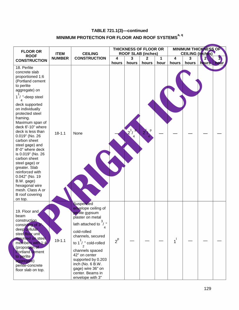
129
TABLE 721.1(3)—continued
MINIMUM PROTECTION FOR FLOOR AND ROOF SYSTEMSa, q
FLOOR OR ROOF
CONSTRUCTION
ITEM NUMBER
CEILING CONSTRUCTION
THICKNESS OF FLOOR OR ROOF SLAB (inches)
MINIMUM THICKNESS OF CEILING (inches)
4 hours
3 hours
2 hours
1 hour
4 hours
3 hours
2 hours
1 hour
18. Perlite concrete slab proportioned 1:6 (Portland cement to perlite aggregate) on
11/4"-deep steel
deck supported on individually protected steel framing. Maximum span of deck 6′-10" where deck is less than 0.019" (No. 26 carbon sheet steel gage) and 8′-0" where deck is 0.019" (No. 26 carbon sheet steel gage) or greater. Slab reinforced with 0.042" (No. 19 B.W. gage) hexagonal wire mesh. Class A or B roof covering on top.
18-1.1 None — 21/4
p 2
1/4
p — — — — —
19. Floor and beam construction consisting of 3"-deep cellular steel floor unit mounted on steel members with 1:4 (proportion of Portland cement to perlite aggregate) perlite-concrete floor slab on top.
19-1.1
Suspended envelope ceiling of perlite gypsum plaster on metal
lath attached to 3/4"
cold-rolled channels, secured
to 11/2" cold-rolled
channels spaced 42" on center supported by 0.203 inch (No. 6 B.W. gage) wire 36" on center. Beams in envelope with 3"
2p — — — 1
l — — —

130
minimum airspace between beam soffit and lath have a 4-hour rating.
(continued)
TABLE 721.1(3)—continued
MINIMUM PROTECTION FOR FLOOR AND ROOF SYSTEMSa, q
FLOOR OR ROOF
CONSTRUCTION
ITEM NUMBER
CEILING CONSTRUCTION
THICKNESS OF FLOOR OR ROOF SLAB (inches)
MINIMUM THICKNESS OF CEILING (inches)
4 hours
3 hours
2 hours
1 hour
4 hours
3 hours
2 hours
1 hour
20. Perlite concrete proportioned 1:6 (Portland cement to perlite aggregate) poured
to 1/8" thickness
above top of corrugations of 15
/16
"-deep
galvanized steel deck maximum span 8′-0" for 0.024" (No. 24 galvanized sheet gage) or 6′-0" for 0.019" (No. 26 galvanized sheet gage) with deck supported by individually protected steel framing. Approved polystyrene foam plastic insulation board having a flame spread not exceeding 75 (1" to 4" thickness) with vent holes that approximate 3 percent of the board surface area placed on top of perlite slurry. A 2′ by 4′ insulation board contains six
20-1.1 None — — Varies — — — — —

131
23/4" diameter
holes. Board
covered with 21/4"
minimum perlite concrete slab. Slab reinforced with mesh consisting of 0.042" (No.19 B.W. gage) galvanized steel wire twisted together to form 2" hexagons with straight 0.065" (No. 16 B.W. gage) galvanized steel wire woven into mesh and spaced 3". Alternate slab reinforcement shall be permitted to consist of 4" × 8", 0.109/0.238" (No. 12/4 B.W. gage), or 2" × 2", 0.083/0.083" (No. 14/14 B.W. gage) welded wire fabric. Class A or B roof covering on top.
(continued)

132
TABLE 721.1(3)—continued
MINIMUM PROTECTION FOR FLOOR AND ROOF SYSTEMSa, q
FLOOR OR ROOF
CONSTRUCTION
ITEM NUMBER
CEILING CONSTRUCTION
THICKNESS OF FLOOR OR ROOF SLAB (inches)
MINIMUM THICKNESS OF CEILING (inches)
4 hours
3 hours
2 hours
1 hour 4
hours 3
hours 2
hours 1
hour
21. Wood joists, wood I-joists, floor trusses and flat or pitched roof trusses spaced a maximum 24" o.c.
with 1/2" wood
structural panels with exterior glue applied at right angles to top of joist or top chord of trusses with 8 dnails. The wood structural panel thickness shall be not less than
nominal 1/2" nor
less than required by Chapter 23.
21-1.1
Base layer 5/8"
Type X gypsum wallboard applied at right angles to joist or truss 24"
o.c. with 11/4"
Type S or Type W drywall screws 24" o.c. Face
layer 5/8" Type X
gypsum wallboard or veneer base applied at right angles to joist or truss through base layer with
17/8" Type S or
Type W drywall screws 12" o.c. at joints and intermediate joist or truss. Face layer Type G drywall screws placed 2" back on either side of face layer end joints, 12" o.c.
— — — Varies — — — 11/4
22. Steel joists, floor trusses and flat or pitched roof trusses spaced a maximum 24" o.c.
with 1/2" wood
structural panels with exterior glue applied at right angles to top of joist or top chord of trusses with No. 8 screws. The wood structural
22-1.1
Base layer 5/8"
Type X gypsum board applied at right angles to steel framing 24" on center with 1" Type S dry wall screws spaced 24" on center.
Face layer 5/8"
Type X gypsum board applied at right angles to
— — — Varies — — — 11/4

133
panel thickness shall be not less
than nominal 1/2"
nor less than required by Chapter 23.
steel framing attached through base layer with
15/8" Type S dry
wall screws 12" on center at end joints and intermediate
joints and 11/2"
Type G dry wall screws 12 inches on center placed 2" back on either side of face layer end joints. Joints of the face layer are offset 24" from the joints of the base layer.
23. Wood I-joist (minimum joist
depth 91/4" with a
minimum flange
depth of 15
/16
"
and a minimum flange cross-sectional area of 2.25 square inches) at 24" o.c. spacing with a minimum 1 × 4
(3/4" × 3.5"actual)
ledger strip applied parallel to and covering the bottom of the bottom flange of each member, tacked in place. 2" mineral wool insulation, 3.5 pcf (nominal) installed adjacent to the bottom flange of the I-joist and supported by the 1 × 4 ledger strip.
23-1.1
1/2"-deep single-
leg resilient channel 16" on center (channels doubled at wallboard end joints), placed perpendicular to the furring strip and joist and attached to each
joist by 17/8" Type
S drywall screws. 5/8" Type C
gypsum wallboard applied perpendicular to the channel with end joints staggered not less than 4′ and fastened with
11/8" Type S
drywall screws spaced 7" on center. Wallboard joints to be taped and covered with joint compound.
— — — Varies — — — 5/8
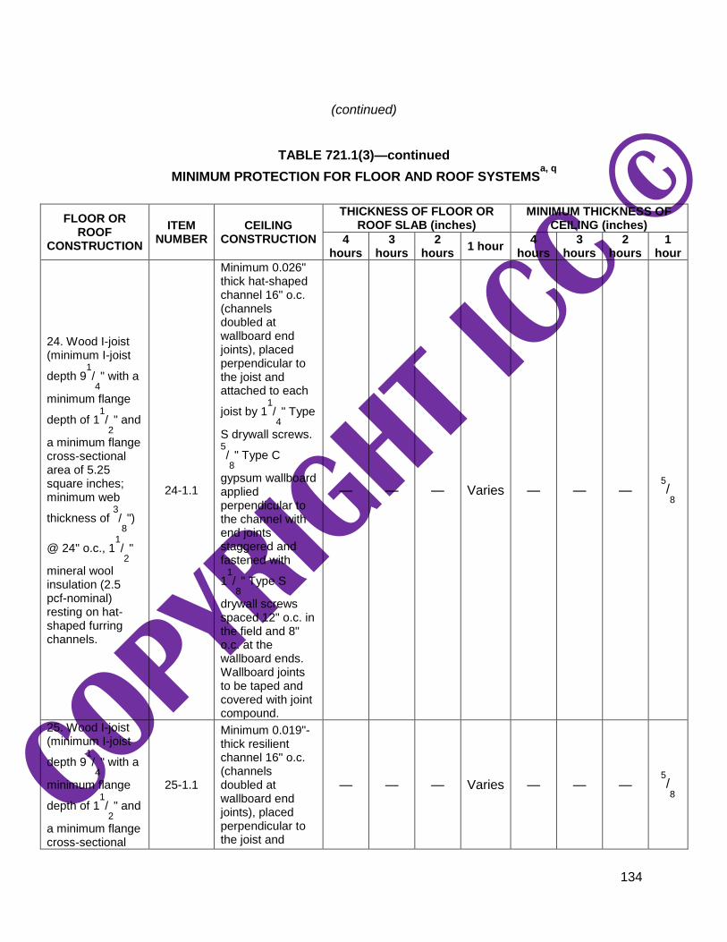
134
(continued)
TABLE 721.1(3)—continued
MINIMUM PROTECTION FOR FLOOR AND ROOF SYSTEMSa, q
FLOOR OR ROOF
CONSTRUCTION
ITEM NUMBER
CEILING CONSTRUCTION
THICKNESS OF FLOOR OR ROOF SLAB (inches)
MINIMUM THICKNESS OF CEILING (inches)
4 hours
3 hours
2 hours
1 hour 4
hours 3
hours 2
hours 1
hour
24. Wood I-joist (minimum I-joist
depth 91/4" with a
minimum flange
depth of 11/2" and
a minimum flange cross-sectional area of 5.25 square inches; minimum web
thickness of 3/8")
@ 24" o.c., 11/2"
mineral wool insulation (2.5 pcf-nominal) resting on hat-shaped furring channels.
24-1.1
Minimum 0.026" thick hat-shaped channel 16" o.c. (channels doubled at wallboard end joints), placed perpendicular to the joist and attached to each
joist by 11/4" Type
S drywall screws. 5/8" Type C
gypsum wallboard applied perpendicular to the channel with end joints staggered and fastened with
11/8" Type S
drywall screws spaced 12" o.c. in the field and 8" o.c. at the wallboard ends. Wallboard joints to be taped and covered with joint compound.
— — — Varies — — — 5/8
25. Wood I-joist (minimum I-joist
depth 91/4" with a
minimum flange
depth of 11/2" and
a minimum flange cross-sectional
25-1.1
Minimum 0.019"-thick resilient channel 16" o.c. (channels doubled at wallboard end joints), placed perpendicular to the joist and
— — — Varies — — — 5/8

135
area of 5.25 square inches; minimum web
thickness of 7/16
")
@ 24" o.c., 11/2"
mineral wool insulation (2.5 pcf-nominal) resting on resilient channels.
attached to each
joist by 15/8" Type
S drywall screws. 5/8" Type C
gypsum wallboard applied perpendicular to the channel with end joints staggered and fastened with 1" Type S drywall screws spaced 12" o.c. in the field and 8" o.c. at the wallboard ends. Wallboard joints to be taped and covered with joint compound.
26. Wood I-joist (minimum I-joist
depth 91/4" with a
minimum flange
thickness of 11/2"
and a minimum flange cross-sectional area of 2.25 square inches; minimum web thick-ness of 3/8") @ 24" o.c.
26-1.1
Two layers of 1/2"
Type X gypsum wallboard applied with the long dimension perpendicular to the I-joists with end joints staggered. The base layer is fastened with
15/8" Type S dry
wall screws spaced 12" o.c. and the face layer is fastened with 2" Type S drywall screws spaced 12" o.c. in the field and 8" o.c. on the edges. Face layer end joints shall not occur on the same I-joist as base layer end joints and edge joints shall be offset 24"from base layer joints. Face layer to also
— — — Varies — — — 1

136
be attached to base layer with
11/2" Type G
drywall screws spaced 8" o.c. placed 6" from face layer end joints. Face layer wallboard joints to be taped and covered with joint compound.
(continued)
TABLE 721.1(3)—continued
MINIMUM PROTECTION FOR FLOOR AND ROOF SYSTEMSa, q
FLOOR OR ROOF
CONSTRUCTION
ITEM NUMBER
CEILING CONSTRUCTION
THICKNESS OF FLOOR OR ROOF SLAB (inches)
MINIMUM THICKNESS OF CEILING (inches)
4 hours
3 hours
2 hours
1 hour 4
hours 3
hours 2
hours 1
hour
27. Wood I-joist (minimum I-joist
depth 91/2" with a
minimum flange
depth of 15
/16
" and
a minimum flange cross-sectional area of 1.95 square inches; minimum web
thickness of 3/8")
@ 24" o.c.
27-1.1
Minimum 0.019" thick resilient channel 16" o.c. (channels doubled at wallboard end joints), placed perpendicular to the joist and attached to each
joist by 11/4" Type
S drywall screws.
Two layers of 1/2"
Type X gypsum wallboard applied with the long dimension perpendicular to the resilient channels with end joints staggered. The base layer is fastened with
11/4" Type S
drywall screws spaced 12" o.c.
— — — Varies — — — 1

137
and the face layer is fastened with
15/8" Type S
drywall screws spaced 12" o.c. Face layer end joints shall not occur on the same I-joist as base layer end joints and edge joints shall be offset 24" from base layer joints. Face layer to also be attached to base layer with
11/2" Type G
drywall screws spaced 8" o.c. placed 6" from face layer end joints. Face layer wallboard joints to be taped and covered with joint compound.
28. Wood I-joist (minimum I-joist
depth 91/4" with a
minimum flange
depth of 11/2" and
a minimum flange cross-sectional area of 2.25 square inches; minimum web
thickness of 3/8")
@ 24" o.c. Unfaced fiberglass insulation or mineral wool insulation is installed between the I-joists supported on the upper surface of the flange by stay wires spaced 12" o.c.
28-1.1
Base layer of 5/8"
Type C gypsum wallboard attached directly to I-joists with
15/8" Type S
drywall screws spaced 12" o.c. with ends staggered. Minimum 0.0179"-thick hat-
shaped 7/8-inch
furring channel 16" o.c. (channels doubled at wallboard end joints), placed perpendicular to the joist and attached to each
joist by 15/8" Type
— — — Varies — — 23/4 —
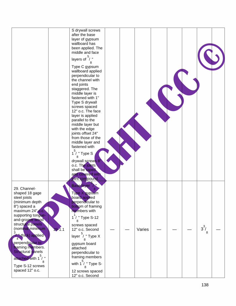
138
S drywall screws after the base layer of gypsum wallboard has been applied. The middle and face
layers of 5/8"
Type C gypsum wallboard applied perpendicular to the channel with end joints staggered. The middle layer is fastened with 1" Type S drywall screws spaced 12" o.c. The face layer is applied parallel to the middle layer but with the edge joints offset 24" from those of the middle layer and fastened with
15/8" Type S
drywall screws 8" o.c. The joints shall be taped and covered with joint compound.
29. Channel-shaped 18 gage steel joists (minimum depth 8") spaced a maximum 24" o.c. supporting tongue-and-groove wood structural panels (nominal minimum 3/4"-thick) applied
perpendicular to framing members. Structural panels
attached with 15/8"
Type S-12 screws spaced 12" o.c.
29-1.1
Base layer 5/8"
Type X gypsum board applied perpendicular to bottom of framing members with
11/8" Type S-12
screws spaced 12" o.c. Second
layer 5/8" Type X
gypsum board attached perpendicular to framing members
with 15/8" Type S-
12 screws spaced 12" o.c. Second
— — Varies — — — 33/8 —

139
layer joints offset 24" from base layer. Third layer 5/8" Type X gypsum board attached perpendicular to framing members
with 23/8" Type S-
12 screws spaced 12" o.c. Third layer joints offset 12" from second layer joints. Hat-
shaped 7/8-inch
rigid furring channels applied at right angles to framing members over third layer
with two 23/8"
TypeS-12 screws at each framing member. Face
layer 5/8" Type X
gypsum board applied at right angles to furring channels with
11/8" Type S
screws spaced 12" o.c.
(continued)
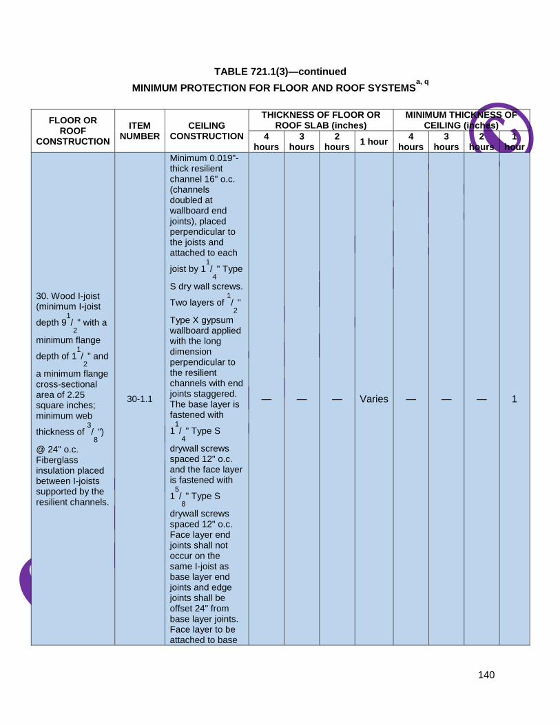
140
TABLE 721.1(3)—continued
MINIMUM PROTECTION FOR FLOOR AND ROOF SYSTEMSa, q
FLOOR OR ROOF
CONSTRUCTION
ITEM NUMBER
CEILING CONSTRUCTION
THICKNESS OF FLOOR OR ROOF SLAB (inches)
MINIMUM THICKNESS OF CEILING (inches)
4 hours
3 hours
2 hours
1 hour 4
hours 3
hours 2
hours 1
hour
30. Wood I-joist (minimum I-joist
depth 91/2" with a
minimum flange
depth of 11/2" and
a minimum flange cross-sectional area of 2.25 square inches; minimum web
thickness of 3/8")
@ 24" o.c. Fiberglass insulation placed between I-joists supported by the resilient channels.
30-1.1
Minimum 0.019"-thick resilient channel 16" o.c. (channels doubled at wallboard end joints), placed perpendicular to the joists and attached to each
joist by 11/4" Type
S dry wall screws.
Two layers of 1/2"
Type X gypsum wallboard applied with the long dimension perpendicular to the resilient channels with end joints staggered. The base layer is fastened with
11/4" Type S
drywall screws spaced 12" o.c. and the face layer is fastened with
15/8" Type S
drywall screws spaced 12" o.c. Face layer end joints shall not occur on the same I-joist as base layer end joints and edge joints shall be offset 24" from base layer joints. Face layer to be attached to base
— — — Varies — — — 1

141
layer with 11/2"
Type G drywall screws spaced 8" o.c. placed 6" from face layer end joints. Face layer wallboard joints to be taped and covered with joint compound.
For SI: 1 inch = 25.4 mm, 1 foot = 304.8 mm, 1 pound = 0.454 kg, 1 cubic foot = 0.0283 m3,
1 pound per square inch = 6.895 kPa, 1 pound per linear foot = 1.4882 kg/m. a. Staples with equivalent holding power and penetration shall be permitted to be used as alternate fasteners to
nails for attachment to wood framing.
b. Where the slab is in an unrestrained condition, minimum reinforcement cover shall be not less than 15/8 inches
for 4 hours (siliceous aggregate only); 11/4
inches for 4 and 3 hours; 1 inch for 2 hours (siliceous aggregate
only); and 3/4 inch for all other restrained and unrestrained conditions.
c. For all of the construction with gypsum wallboard described in this table, gypsum base for veneer plaster of the same size, thickness and core type shall be permitted to be substituted for gypsum wallboard, provided that attachment is identical to that specified for the wallboard, and the joints on the face layer are reinforced and the
entire surface is covered with not less than 1/16
-inch gypsum veneer plaster.
d. Slab thickness over steel joists measured at the joists for metal lath form and at the top of the form for steel form units.
e. (a) The maximum allowable stress level for H-Series joists shall not exceed 22,000 psi. (b) The allowable stress for K-Series joists shall not exceed 26,000 psi, the nominal depth of such joist shall be
not less than 10 inches and the nominal joist weight shall be not less than 5 pounds per linear foot. f. Cement plaster with 15 pounds of hydrated lime and 3 pounds of approved additives or admixtures per bag of
cement.
g. Gypsum wallboard ceilings attached to steel framing shall be permitted to be suspended with 11/2-inch cold-
formed carrying channels spaced 48 inches on center, that are suspended with No. 8 SWG galvanized wire hangers spaced 48 inches on center. Cross-furring channels are tied to the carrying channels with No. 18 SWG galvanized wire hangers spaced 48 inches on center. Cross-furring channels are tied to the carrying channels with No. 18 SWG galvanized wire (double strand) and spaced as required for direct attachment to the framing. This alternative is applicable to those steel framing assemblies recognized under Note q.
h. Six-inch hollow clay tile with 2-inch concrete slab above.
i. Four-inch hollow clay tile with 11/2-inch concrete slab above.
j. Thickness measured to bottom of steel form units.
k. Five-eighths inch of vermiculite gypsum plaster plus 1/2 inch of approved vermiculite acoustical plastic.
l. Furring channels spaced 12 inches on center. m. Double wood floor shall be permitted to be either of the following:
(a) Subfloor of 1-inch nominal boarding, a layer of asbestos paper weighing not less than 14 pounds per 100 square feet and a layer of 1-inch nominal tongue-and-groove finished flooring.
142
(b) Subfloor of 1-inch nominal tongue-and-groove boarding or 15
/32
-inch wood structural panels with exterior
glue and a layer of 1-inch nominal tongue-and-groove finished flooring or 19
/32
-inch wood structural panel
finish flooring or a layer of Type I Grade M-1 particleboard not less than 5/8-inch thick.
n. The ceiling shall be permitted to be omitted over unusable space, and flooring shall be permitted to be omitted where unusable space occurs above.
o. For properties of cooler or wallboard nails, see ASTM C514, ASTM C547 or ASTM F1667. p. Thickness measured on top of steel deck unit. q. Generic fire-resistance ratings (those not designated as PROPRIETARY* in the listing) in the GA 600 shall be
accepted as if herein specified.
721.1.1 Thickness of protective coverings. The thickness of fire-resistant materials required for protection of structural members shall be not less than set forth in Table 721.1(1), except as modified in this section. The figures shown shall be the net thickness of the protecting materials and shall not include any hollow space in back of the protection.
721.1.2 Unit masonry protection. Where required, metal ties shall be embedded in bed joints of unit masonry for protection of steel columns. Such ties shall be as set forth in Table 721.1(1) or be equivalent thereto.
721.1.3 Reinforcement for cast-in-place concrete column protection. Cast-in-place concrete protection for steel columns shall be reinforced at the edges of such members with wire ties of not less than 0.18 inch (4.6 mm) in diameter wound spirally around the columns on a pitch of not more than 8 inches (203 mm) or by equivalent reinforcement.
721.1.4 Plaster application. The finish coat is not required for plaster protective coatings where those coatings comply with the design mix and thickness requirements of Tables 721.1(1), 721.1(2) and 721.1(3).
721.1.5 Bonded prestressed concrete tendons. For members having a single tendon or more than one tendon installed with equal concrete cover measured from the nearest surface, the cover shall be not less than that set forth in Table 721.1(1). For members having multiple tendons installed with variable concrete cover, the average tendon cover shall be not less than that set forth in Table 721.1(1), provided that:
1. The clearance from each tendon to the nearest exposed surface is used to
determine the average cover.
2. The clear cover for individual tendons shall not be less than one-half of that set forth
in Table 721.1(1). A minimum cover of 3/4 inch (19.1 mm) for slabs and 1 inch (25
mm) for beams is required for any aggregate concrete.
3. For the purpose of establishing a fire-resistance rating, tendons having a clear
covering less than that set forth in Table 721.1(1) shall not contribute more than 50 percent of the required ultimate moment capacity for members less than 350 square

143
inches (0.226 m2) in cross-sectional area and 65 percent for larger members. For
structural design purposes, however, tendons having a reduced cover are assumed to be fully effective.
SECTION 722
CALCULATED FIRE RESISTANCE 722.1 General. The provisions of this section contain procedures by which the fire resistance of specific materials or combinations of materials is established by calculations. These procedures apply only to the information contained in this section and shall not be otherwise used. The calculated fire resistance of specific materials or combinations of materials shall be established by one of the following:
1. Concrete, concrete masonry and clay masonry assemblies shall be permitted in
accordance with ACI 216.1/TMS 0216.
2. Precast and precast, prestressed concrete assemblies shall be permitted in accordance
with PCI 124.
3. Steel assemblies shall be permitted in accordance with Chapter 5 of ASCE 29.
4. Exposed wood members and wood decking shall be permitted in accordance with
Chapter 16 of ANSI/AWC NDS.
722.2 Concrete assemblies. The provisions of this section contain procedures by which the fire-resistance ratings of concrete assemblies are established by calculations.
722.2.1 Concrete walls. Cast-in-place and precast concrete walls shall comply with Section 722.2.1.1. Multiwythe concrete walls shall comply with Section 722.2.1.2. Joints between precast panels shall comply with Section 722.2.1.3. Concrete walls with gypsum wallboard or plaster finish shall comply with Section 722.2.1.4.
722.2.1.1 Cast-in-place or precast walls. The minimum equivalent thicknesses of cast-in-place or precast concrete walls for fire-resistance ratings of 1 hour to 4 hours are shown in Table 722.2.1.1. For solid walls with flat vertical surfaces, the equivalent thickness is the same as the actual thickness. The values in Table 722.2.1.1 apply to plain, reinforced or prestressed concrete walls.

144
TABLE 722.2.1.1 MINIMUM EQUIVALENT THICKNESS OF CAST-IN-PLACE OR PRECAST CONCRETE
WALLS, LOAD-BEARING OR NONLOAD-BEARING
CONCRETE TYPE
MINIMUM SLAB THICKNESS (inches) FOR FIRE-RESISTANCE RATING OF
1 hour 11/2 hours 2 hours 3 hours 4 hours
Siliceous 3.5 4.3 5.0 6.2 7.0
Carbonate 3.2 4.0 4.6 5.7 6.6
Sand-lightweight 2.7 3.3 3.8 4.6 5.4
Lightweight 2.5 3.1 3.6 4.4 5.1
For SI: 1 inch = 25.4 mm.
722.2.1.1.1 Hollow-core precast wall panels. For hollow-core precast concrete wall panels in which the cores are of constant cross section throughout the length, calculation of the equivalent thickness by dividing the net cross-sectional area (the gross cross section minus the area of the cores) of the panel by its width shall be permitted
722.2.1.1.2 Core spaces filled. Where all of the core spaces of hollow-core wall panels are filled with loose-fill material, such as expanded shale, clay or slag, or vermiculite or perlite, the fire-resistance rating of the wall is the same as that of a solid wall of the same concrete type and of the same overall thickness.
722.2.1.1.3 Tapered cross sections. The thickness of panels with tapered cross sections shall be that determined at a distance 2t or 6 inches (152 mm), whichever is less, from the point of minimum thickness, where t is the minimum thickness.
722.2.1.1.4 Ribbed or undulating surfaces. The equivalent thickness of panels with ribbed or undulating surfaces shall be determined by one of the following expressions:
For s 4t, the thickness to be used shall be t
For s 2t, the thickness to be used shall be t
e
For 4t s 2t, the thickness to be used shall be
(Equation 7-3)
where:
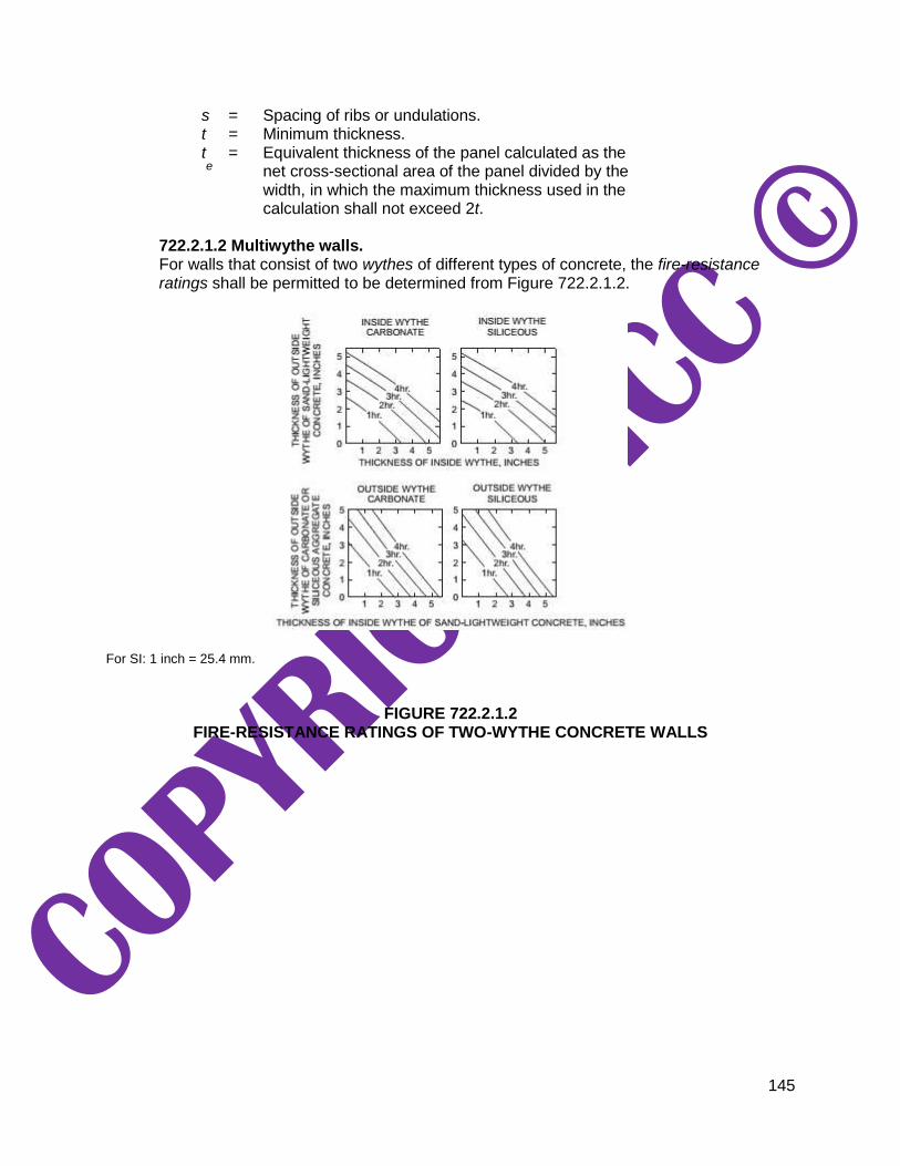
145
s = Spacing of ribs or undulations. t = Minimum thickness. te = Equivalent thickness of the panel calculated as the
net cross-sectional area of the panel divided by the width, in which the maximum thickness used in the calculation shall not exceed 2t.
722.2.1.2 Multiwythe walls. For walls that consist of two wythes of different types of concrete, the fire-resistance ratings shall be permitted to be determined from Figure 722.2.1.2.
For SI: 1 inch = 25.4 mm.
FIGURE 722.2.1.2 FIRE-RESISTANCE RATINGS OF TWO-WYTHE CONCRETE WALLS

146
TABLE 722.2.1.2(1)
VALUES OF Rn
0.59 FOR USE IN EQUATION 7-4
TYPE OF MATERIAL
THICKNESS OF MATERIAL (inches)
11/2 2 2
1/2 3 3
1/2 4 4
1/2 5 5
1/2 6 6
1/2 7
Siliceous aggregate concrete
5.3 6.5 8.1 9.5 11.3 13.0 14.9 16.9 18.8 20.7 22.8 25.1
Carbonate aggregate concrete
5.5 7.1 8.9 10.4 12.0 14.0 16.2 18.1 20.3 21.9 24.7 27.2c
Sand-lightweight concrete
6.5 8.2 10.5 12.8 15.5 18.1 20.7 23.3 26.0c
Note c
Note c
Note c
Lightweight concrete
6.6 8.8 11.2 13.7 16.5 19.1 21.9 24.7 27.8c
Note c
Note c
Note c
Insulating
concretea
9.3 13.3 16.6 18.3 23.1 26.5c
Note c
Note c
Note c
Note c
Note c
Note c
Airspaceb — — — — — — — — — — — —
For SI: 1 inch = 25.4 mm, 1 pound per cubic foot = 16.02 kg/m3.
a. Dry unit weight of 35 pcf or less and consisting of cellular, perlite or vermiculite concrete.
b. The Rn
0.59 value for one
1/2" to 3
1/2" airspace is 3.3. The R
n
0.59 value for two
1/2" to
3
1/2" airspaces is 6.7.
c. The fire-resistance rating for this thickness exceeds 4 hours.
TABLE 722.2.1.2(2)
FIRE-RESISTANCE RATINGS BASED ON R0.59
Ra, MINUTES R
0.59
60 11.20
120 16.85
180 21.41
240 25.37
a. Based on Equation 7-4.
722.2.1.2.1 Two or more wythes. The fire-resistance rating for wall panels consisting of two or more wythes shall be permitted to be determined by the formula:
(Equation 7-4)
where:
R = The fire endurance of the assembly, minutes.
147
R1, R
2,
and Rn
= The fire endurances of the individual wythes, minutes. Values of Rn
0.59 for use in Equation 7-4 are given in Table 722.2.1.2(1). Calculated fire-resistance ratings are shown in Table 722.2.1.2(2).
722.2.1.2.2 Foam plastic insulation. The fire-resistance ratings of precast concrete wall panels consisting of a layer of foam plastic insulation sandwiched between two wythes of concrete shall be permitted to be determined by use of Equation 7-4. Foam plastic insulation with a total thickness of less than 1 inch (25 mm) shall be disregarded. The Rn value for thickness of foam plastic insulation of 1 inch (25 mm) or greater, for use in the calculation, is 5 minutes; therefore Rn
0.59 = 2.5.
722.2.1.3 Joints between precast wall panels. Joints between precast concrete wall panels that are not insulated as required by this section shall be considered as openings in walls. Uninsulated joints shall be included in determining the percentage of openings permitted by Table 705.8. Where openings are not permitted or are required by this code to be protected, the provisions of this section shall be used to determine the amount of joint insulation required. Insulated joints shall not be considered openings for purposes of determining compliance with the allowable percentage of openings in Table 705.8.
722.2.1.3.1 Ceramic fiber joint protection. Figure 722.2.1.3.1 shows thicknesses of ceramic fiber blankets to be used to insulate joints between precast concrete wall panels for various panel thicknesses
and for joint widths of 3/8 inch (9.5 mm) and 1 inch (25 mm) for fire-resistance ratings
of 1 hour to 4 hours. For joint widths between 3/8 inch (9.5 mm) and 1 inch (25 mm),
the thickness of ceramic fiber blanket is allowed to be determined by direct interpolation. Other tested and labeled materials are acceptable in place of ceramic fiber blankets.

148
For SI: 1 inch = 25.4 mm.
FIGURE 722.2.1.3.1 CERAMIC FIBER JOINT PROTECTION
722.2.1.4 Walls with gypsum wallboard or plaster finishes. The fire-resistance rating of cast-in-place or precast concrete walls with finishes of gypsum wallboard or plaster applied to one or both sides shall be permitted to be calculated in accordance with the provisions of this section.

149
TABLE 722.2.1.4(1) MULTIPLYING FACTOR FOR FINISHES ON NONFIRE-EXPOSED SIDE OF WALL
TYPE OF FINISH APPLIED
TO CONCRETE OR CONCRETE
MASONRY WALL
TYPE OF AGGREGATE USED IN CONCRETE OR CONCRETE MASONRY
Concrete: siliceous
or carbonate concrete masonry:
siliceous or carbonate;
solid clay brick
Concrete: sand-lightweight concrete
masonry: clay tile;
hollow clay brick; concrete
masonry units of expanded
shale and < 20% sand
Concrete: lightweight
concrete masonry: concrete
masonry units of expanded
shale, expanded clay, expanded slag,
or pumice < 20% sand
Concrete masonry: concrete masonry units of
expanded slag,
expanded clay,
or pumice
Portland cement-sand plaster
1.00 0.75a 0.75
a 0.50
a
Gypsum-sand plaster 1.25 1.00 1.00 1.00
Gypsum-vermiculite or perlite plaster
1.75 1.50 1.25 1.25
Gypsum wallboard 3.00 2.25 2.25 2.25
For SI: 1 inch = 25.4 mm.
a. For Portland cement-sand plaster 5/8 inch or less in thickness and applied directly to the concrete or concrete
masonry on the nonfire-exposed side of the wall, the multiplying factor shall be 1.00.

150
TABLE 722.2.1.4(2) TIME ASSIGNED TO FINISH MATERIALS ON FIRE-EXPOSED SIDE OF WALL
FINISH DESCRIPTION TIME (minutes)
Gypsum wallboard 3/8 inch 10
1/2 inch 15
5/8 inch 20
2 layers of 3/8 inch 25
1 layer of 3/8 inch, 1 layer of
1/2 inch 35
2 layers of 1/2 inch 40
Type X gypsum wallboard 1/2 inch 25
5/8 inch 40
Portland cement-sand plaster applied directly to concrete masonry See Note a
Portland cement-sand plaster on metal lath
3/4
inch 20
7/8
inch 25
1 inch 30
Gypsum sand plaster on 3/8-inch gypsum lath
1/2
inch 35
5/8
inch 40
3/4
inch 50
Gypsum sand plaster on metal lath 3/4
inch 50
7/8
inch 60
1 inch 80
For SI: 1 inch = 25.4 mm.
a. The actual thickness of Portland cement-sand plaster, provided that it is 5/8 inch or less in thickness, shall be
permitted to be included in determining the equivalent thickness of the masonry for use in Table 722.3.2.

151
722.2.1.4.1 Nonfire-exposed side. Where the finish of gypsum wallboard or plaster is applied to the side of the wall not exposed to fire, the contribution of the finish to the total fire-resistance rating shall be determined as follows: The thickness of the finish shall first be corrected by multiplying the actual thickness of the finish by the applicable factor determined from Table 722.2.1.4(1) based on the type of aggregate in the concrete. The corrected thickness of finish shall then be added to the actual or equivalent thickness of concrete and fire-resistance rating of the concrete and finish determined from Tables 722.2.1.1 and 722.2.1.2(1) and Figure 722.2.1.2.
722.2.1.4.2 Fire-exposed side. Where gypsum wallboard or plaster is applied to the fire-exposed side of the wall, the contribution of the finish to the total fire-resistance rating shall be determined as follows: The time assigned to the finish as established by Table 722.2.1.4(2) shall be added to the fire-resistance rating determined from Tables 722.2.1.1 and 722.2.1.2(1) and Figure 722.2.1.2 for the concrete alone, or to the rating determined in Section 722.2.1.4.1 for the concrete and finish on the nonfire-exposed side.
722.2.1.4.3 Nonsymmetrical assemblies. For a wall without finish on one side or having different types or thicknesses of finish on each side, the calculation procedures of Sections 722.2.1.4.1 and 722.2.1.4.2 shall be performed twice, assuming either side of the wall to be the fire-exposed side. The fire-resistance rating of the wall shall not exceed the lower of the two values.
Exception: For an exterior wall with a fire separation distance greater than 5 feet (1524 mm) the fire shall be assumed to occur on the interior side only.
722.2.1.4.4 Minimum concrete fire-resistance rating. Where finishes applied to one or both sides of a concrete wall contribute to the fire-resistance rating, the concrete alone shall provide not less than one-half of the total required fire-resistance rating. Additionally, the contribution to the fire resistance of the finish on the nonfire-exposed side of a load-bearing wall shall not exceed one-half the contribution of the concrete alone.
722.2.1.4.5 Concrete finishes. Finishes on concrete walls that are assumed to contribute to the total fire-resistance rating of the wall shall comply with the installation requirements of Section 722.3.2.5.
722.2.2 Concrete floor and roof slabs. Reinforced and prestressed floors and roofs shall comply with Section 722.2.2.1. Multicourse floors and roofs shall comply with Sections 722.2.2.2 and 722.2.2.3, respectively.
722.2.2.1 Reinforced and prestressed floors and roofs. The minimum thicknesses of reinforced and prestressed concrete floor or roof slabs for fire-resistance ratings of 1 hour to 4 hours are shown in Table 722.2.2.1.
Exception: Minimum thickness shall not be required for floors and ramps within parking garages constructed in accordance with Sections 406.5 and 406.6.

152
TABLE 722.2.2.1 MINIMUM SLAB THICKNESS (inches)
CONCRETE TYPE
FIRE-RESISTANCE RATING (hours)
1 11/2 2 3 4
Siliceous 3.5 4.3 5 6.2 7
Carbonate 3.2 4 4.6 5.7 6.6
Sand-lightweight 2.7 3.3 3.8 4.6 5.4
Lightweight 2.5 3.1 3.6 4.4 5.1
For SI: 1 inch = 25.4 mm.
722.2.2.1.1 Hollow-core prestressed slabs. For hollow-core prestressed concrete slabs in which the cores are of constant cross section throughout the length, the equivalent thickness shall be permitted to be obtained by dividing the net cross-sectional area of the slab including grout in the joints, by its width.
722.2.2.1.2 Slabs with sloping soffits. The thickness of slabs with sloping soffits (see Figure 722.2.2.1.2) shall be determined at a distance 2t or 6 inches (152 mm), whichever is less, from the point of minimum thickness, where t is the minimum thickness.
For SI: 1 inch = 25.4 mm.
FIGURE 722.2.2.1.2 DETERMINATION OF SLAB
THICKNESS FOR SLOPING SOFFITS
722.2.2.1.3 Slabs with ribbed soffits. The thickness of slabs with ribbed or undulating soffits (see Figure 722.2.2.1.3) shall be determined by one of the following expressions, whichever is applicable:
For s > 4t, the thickness to be used shall be t
For s 2t, the thickness to be used shall be te
For 4t > s > 2t, the thickness to be used shall be

153
(Equation 7-5)
where:
s = Spacing of ribs or undulations. t = Minimum thickness. te = Equivalent thickness of the slab calculated as the
net area of the slab divided by the width, in which the maximum thickness used in the calculation shall not exceed 2t.
For SI: 1 inch = 25.4 mm
FIGURE 722.2.2.1.3 SLABS WITH RIBBED OR UNDULATING SOFFITS
722.2.2.1.4 Flat plate concrete slabs with uniformly spaced hollow voids. Table 722.2.2.1 shall be used to determine the 1- and 2-hour fire-resistance ratings for flat plate concrete slabs with uniformly spaced hollow voids. The equivalent thickness of the slab shall be determined by dividing the net concrete volume of the slab by the floor area. The net concrete volume of the slab shall be equal to the volume of concrete of a solid slab minus the average concrete volume displaced by the hollow voids.
722.2.2.2 Multicourse floors. The fire-resistance ratings of floors that consist of a base slab of concrete with a topping (overlay) of a different type of concrete shall comply with Figure 722.2.2.2.

154
For SI: 1 inch = 25.4 mm.
FIGURE 722.2.2.2 FIRE-RESISTANCE RATINGS FOR
TWO-COURSE CONCRETE FLOORS
722.2.2.3 Multicourse roofs. The fire-resistance ratings of roofs that consist of a base slab of concrete with a topping (overlay) of an insulating concrete or with an insulating board and built-up roofing shall comply with Figures 722.2.2.3(1) and 722.2.2.3(2).

155
For SI: 1 inch = 25.4 mm.
FIGURE 722.2.2.3(1) FIRE-RESISTANCE RATINGS
FOR CONCRETE ROOF ASSEMBLIES
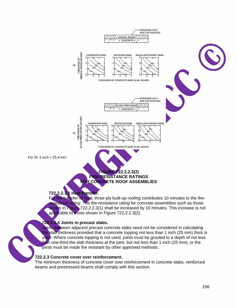
156
For SI: 1 inch = 25.4 mm.
FIGURE 722.2.2.3(2) FIRE-RESISTANCE RATINGS
FOR CONCRETE ROOF ASSEMBLIES
722.2.2.3.1 Heat transfer. For the transfer of heat, three-ply built-up roofing contributes 10 minutes to the fire-resistance rating. The fire-resistance rating for concrete assemblies such as those shown in Figure 722.2.2.3(1) shall be increased by 10 minutes. This increase is not applicable to those shown in Figure 722.2.2.3(2).
722.2.2.4 Joints in precast slabs. Joints between adjacent precast concrete slabs need not be considered in calculating the slab thickness provided that a concrete topping not less than 1 inch (25 mm) thick is used. Where concrete topping is not used, joints must be grouted to a depth of not less than one-third the slab thickness at the joint, but not less than 1 inch (25 mm), or the joints must be made fire resistant by other approved methods.
722.2.3 Concrete cover over reinforcement. The minimum thickness of concrete cover over reinforcement in concrete slabs, reinforced beams and prestressed beams shall comply with this section.

157
TABLE 722.2.3(1) COVER THICKNESS FOR REINFORCED CONCRETE FLOOR OR ROOF SLABS (inches)
CONCRETE AGGREGATE TYPE
FIRE-RESISTANCE RATING (hours)
Restrained Unrestrained
1 11/2 2 3 4 1 1
1/2 2 3 4
Siliceous 3/4
3/4
3/4
3/4
3/4
3/4
3/4 1 1
1/4 1
5/8
Carbonate 3/4
3/4
3/4
3/4
3/4
3/4
3/4
3/4 1
1/4 1
1/4
Sand-lightweight or lightweight 3/4
3/4
3/4
3/4
3/4
3/4
3/4
3/4 1
1/4 1
1/4
For SI: 1 inch = 25.4 mm.
TABLE 722.2.3(2) COVER THICKNESS FOR PRESTRESSED CONCRETE FLOOR OR ROOF SLABS (inches)
CONCRETE AGGREGATE TYPE
FIRE-RESISTANCE RATING (hours)
Restrained Unrestrained
1 11/2 2 3 4 1 1
1/2 2 3 4
Siliceous 3/4
3/4
3/4
3/4
3/4 1
1/8 1
1/2 1
3/4 2
3/8 2
3/4
Carbonate 3/4
3/4
3/4
3/4
3/4 1 1
3/8 1
5/8 2
1/8 2
1/4
Sand-lightweight or lightweight 3/4
3/4
3/4
3/4
3/4 1 1
3/8 1
1/2 2 2
1/4
For SI: 1 inch = 25.4 mm.

158
TABLE 722.2.3(3) MINIMUM COVER FOR MAIN REINFORCING BARS OF REINFORCED CONCRETE
BEAMSc (APPLICABLE TO ALL TYPES OF STRUCTURAL CONCRETE)
RESTRAINED OR
UNRESTRAINEDa
BEAM
WIDTHb(inches)
FIRE-RESISTANCE RATING (hours)
1 11/2 2 3 4
Restrained
5
3/4
3/4
3/4 1
a 1
1/4
a
7 3/4
3/4
3/4
3/4
3/4
≥ 10 3/4
3/4
3/4
3/4
3/4
Unrestrained
5 3/4 1 1
1/4 — —
7 3/4
3/4
3/4 1
3/4 3
≥ 10 3/4
3/4
3/4
1 1
3/4
For SI: 1 inch = 25.4 mm, 1 foot = 304.8 mm. a. Tabulated values for restrained assemblies apply to beams spaced more than 4 feet on center. For restrained
beams spaced 4 feet or less on center, minimum cover of 3/4
inch is adequate for ratings of 4 hours or less.
b. For beam widths between the tabulated values, the minimum cover thickness can be determined by direct interpolation.
c. The cover for an individual reinforcing bar is the minimum thickness of concrete between the surface of the bar and the fire-exposed surface of the beam. For beams in which several bars are used, the cover for corner bars used in the calculation shall be reduced to one-half of the actual value. The cover for an individual bar must be
not less than one-half of the value given in Table 722.2.3(3) nor less than 3/4
inch.

159
TABLE 722.2.3(4) MINIMUM COVER FOR PRESTRESSED CONCRETE BEAMS 8 INCHES OR GREATER IN
WIDTHb
RESTRAINED OR
UNRESTRAINEDa
CONCRETE AGGREGATE
TYPE
BEAM WIDTH (inches)
FIRE-RESISTANCE RATING (hours)
1 11/2 2 3 4
Restrained
Carbonate or siliceous
8 11/2 1
1/2 1
1/2 1
3/4
a 2
1/2
a
Carbonate or siliceous
12 11/2 1
1/2 1
1/2 1
1/2 1
7/8
a
Sand lightweight 8 11/2 1
1/2 1
1/2 1
1/2 2
a
Sand lightweight 12 11/2 1
1/2 1
1/2 1
1/2 1
5/8
a
Unrestrained
Carbonate or siliceous
8 11/2 1
3/4 2
1/2 5
c —
Carbonate or siliceous
12 11/2 1
1/2 1
7/8
a 2
1/2 3
Sand lightweight 8 11/2 1
1/2 2 3
1/4 —
Sand lightweight 12 11/2 1
1/2 1
5/8 2 2
1/2
For SI: 1 inch = 25.4 mm, 1 foot = 304.8 mm. a. Tabulated values for restrained assemblies apply to beams spaced more than 4 feet on center. For restrained
beams spaced 4 feet or less on center, minimum cover of 3/4 inch is adequate for 4-hour ratings or less.
b. For beam widths between 8 inches and 12 inches, minimum cover thickness can be determined by direct interpolation.
c. Not practical for 8-inch-wide beam but shown for purposes of interpolation.

160
TABLE 722.2.3(5) MINIMUM COVER FOR PRESTRESSED CONCRETE BEAMS OF ALL WIDTHS
RESTRAINED OR
UNRESTRAINEDa
CONCRETE AGGREGATE TYPE
BEAM
AREAb
A (square inches)
FIRE-RESISTANCE RATING (hours)
1 11/2 2 3 4
Restrained
All 40 A 150 11/2 1
1/2 2 2
1/2 —
Carbonate or siliceous
150 < A 300 11/2 1
1/2 1
1/2 1
3/4 2
1/2
300 < A 11/2 1
1/2 1
1/2 1
1/2 2
Sand lightweight 150 < A 11/2 1
1/2 1
1/2 1
1/2 2
Unrestrained
All 40 A 150 2 21/2 — — —
Carbonate or siliceous
150 < A 300 11/2 1
3/4 2
1/2 — —
300 < A 11/2 1
1/2 2 3
c 4
c
Sand lightweight 150 < A 11/2 1
1/2 2 3
c 4
c
For SI: 1 inch = 25.4 mm, 1 foot = 304.8 mm, 1 square inch = 645.2 mm2.
a. Tabulated values for restrained assemblies apply to beams spaced more than 4 feet on center. For restrained
beams spaced 4 feet or less on center, minimum cover of 3/4
inch is adequate for 4-hour ratings or less.
b. The cross-sectional area of a stem is permitted to include a portion of the area in the flange, provided that the width of the flange used in the calculation does not exceed three times the average width of the stem.
c. U-shaped or hooped stirrups spaced not to exceed the depth of the member and having a minimum cover of 1 inch shall be provided.
722.2.3.1 Slab cover. The minimum thickness of concrete cover to the positive moment reinforcement shall comply with Table 722.2.3(1) for reinforced concrete and Table 722.2.3(2) for prestressed concrete. These tables are applicable for solid or hollow-core one-way or two-way slabs with flat undersurfaces. These tables are applicable to slabs that are either cast in place or precast. For precast prestressed concrete not covered elsewhere, the procedures contained in PCI 124 shall be acceptable.
722.2.3.2 Reinforced beam cover. The minimum thickness of concrete cover to the positive moment reinforcement (bottom steel) for reinforced concrete beams is shown in Table 722.2.3(3) for fire-resistance ratings of 1 hour to 4 hours.
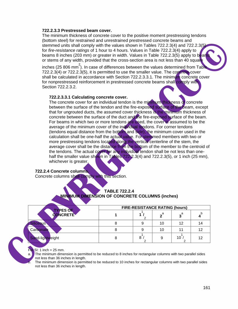
161
722.2.3.3 Prestressed beam cover. The minimum thickness of concrete cover to the positive moment prestressing tendons (bottom steel) for restrained and unrestrained prestressed concrete beams and stemmed units shall comply with the values shown in Tables 722.2.3(4) and 722.2.3(5) for fire-resistance ratings of 1 hour to 4 hours. Values in Table 722.2.3(4) apply to beams 8 inches (203 mm) or greater in width. Values in Table 722.2.3(5) apply to beams or stems of any width, provided that the cross-section area is not less than 40 square
inches (25 806 mm2). In case of differences between the values determined from Table
722.2.3(4) or 722.2.3(5), it is permitted to use the smaller value. The concrete cover shall be calculated in accordance with Section 722.2.3.3.1. The minimum concrete cover for nonprestressed reinforcement in prestressed concrete beams shall comply with Section 722.2.3.2.
722.2.3.3.1 Calculating concrete cover. The concrete cover for an individual tendon is the minimum thickness of concrete between the surface of the tendon and the fire-exposed surface of the beam, except that for ungrouted ducts, the assumed cover thickness is the minimum thickness of concrete between the surface of the duct and the fire-exposed surface of the beam. For beams in which two or more tendons are used, the cover is assumed to be the average of the minimum cover of the individual tendons. For corner tendons (tendons equal distance from the bottom and side), the minimum cover used in the calculation shall be one-half the actual value. For stemmed members with two or more prestressing tendons located along the vertical centerline of the stem, the average cover shall be the distance from the bottom of the member to the centroid of the tendons. The actual cover for any individual tendon shall be not less than one-half the smaller value shown in Tables 722.2.3(4) and 722.2.3(5), or 1 inch (25 mm), whichever is greater.
722.2.4 Concrete columns. Concrete columns shall comply with this section.
TABLE 722.2.4 MINIMUM DIMENSION OF CONCRETE COLUMNS (inches)
TYPES OF CONCRETE
FIRE-RESISTANCE RATING (hours)
1 11/2 2
a 3
a 4
b
Siliceous 8 9 10 12 14
Carbonate 8 9 10 11 12
Sand-lightweight 8 81/2 9 10
1/2 12
For SI: 1 inch = 25 mm. a. The minimum dimension is permitted to be reduced to 8 inches for rectangular columns with two parallel sides
not less than 36 inches in length. b. The minimum dimension is permitted to be reduced to 10 inches for rectangular columns with two parallel sides
not less than 36 inches in length.

162
722.2.4.1 Minimum size. The minimum overall dimensions of reinforced concrete columns for fire-resistance ratings of 1 hour to 4 hours for exposure to fire on all sides shall comply with this section.
722.2.4.1.1 Concrete strength less than or equal to 12,000 psi. For columns made with concrete having a specified compressive strength, f′
c, of less
than or equal to 12,000 psi (82.7 MPa), the minimum dimension shall comply with Table 722.2.4.
722.2.4.1.2 Concrete strength greater than 12,000 psi. For columns made with concrete having a specified compressive strength, f′
c, greater
than 12,000 psi (82.7 MPa), for fire-resistance ratings of 1 hour to 4 hours the minimum dimension shall be 24 inches (610 mm).
722.2.4.2 Minimum cover for R/C columns. The minimum thickness of concrete cover to the main longitudinal reinforcement in columns, regardless of the type of aggregate used in the concrete and the specified compressive strength of concrete, f′
c, shall be not less than 1 inch (25 mm) times the
number of hours of required fire resistance or 2 inches (51 mm), whichever is less.
722.2.4.3 Tie and spiral reinforcement. For concrete columns made with concrete having a specified compressive strength, f′
c,
greater than 12,000 psi (82.7 MPa), tie and spiral reinforcement shall comply with the following:
1. The free ends of rectangular ties shall terminate with a 135-degree (2.4 rad)
standard tie hook.
2. The free ends of circular ties shall terminate with a 90-degree (1.6 rad) standard
tie hook.
3. The free ends of spirals, including at lap splices, shall terminate with a 90-degree
(1.6 rad) standard tie hook.
The hook extension at the free end of ties and spirals shall be the larger of six bar
diameters and the extension required by Section 25.3.2 of ACI 318. Hooks shall project into the core of the column.
722.2.4.4 Columns built into walls. The minimum dimensions of Table 722.2.4 do not apply to a reinforced concrete column that is built into a concrete or masonry wall provided that all of the following are met:
1. The fire-resistance rating for the wall is equal to or greater than the required
rating of the column.
2. The main longitudinal reinforcing in the column has cover not less than that
required by Section 722.2.4.2.

163
3. Openings in the wall are protected in accordance with Section 716.
Where openings in the wall are not protected as required by Section 716, the
minimum dimension of columns required to have a fire-resistance rating of 3 hours or less shall be 8 inches (203 mm), and 10 inches (254 mm) for columns required to have a fire-resistance rating of 4 hours, regardless of the type of aggregate used in the concrete.
722.2.4.5 Precast cover units for steel columns. See Section 722.5.1.4.
722.3 Concrete masonry. The provisions of this section contain procedures by which the fire-resistance ratings of concrete masonry are established by calculations.
722.3.1 Equivalent thickness. The equivalent thickness of concrete masonry construction shall be determined in accordance with the provisions of this section.
722.3.1.1 Concrete masonry unit plus finishes. The equivalent thickness of concrete masonry assemblies, T
ea, shall be computed as
the sum of the equivalent thickness of the concrete masonry unit, Te, as determined by
Section 722.3.1.2, 722.3.1.3 or 722.3.1.4, plus the equivalent thickness of finishes, Tef
,
determined in accordance with Section 722.3.2:
(Equation 7-6)
722.3.1.2 Ungrouted or partially grouted construction. T
e shall be the value obtained for the concrete masonry unit determined in accordance
with ASTM C140.
722.3.1.3 Solid grouted construction. The equivalent thickness, T
e, of solid grouted concrete masonry units is the actual
thickness of the unit.
722.3.1.4 Airspaces and cells filled with loose-fill material. The equivalent thickness of completely filled hollow concrete masonry is the actual thickness of the unit where loose-fill materials are: sand, pea gravel, crushed stone, or slag that meet ASTM C33 requirements; pumice, scoria, expanded shale, expanded clay, expanded slate, expanded slag, expanded fly ash, or cinders that comply with ASTM C331; or perlite or vermiculite meeting the requirements of ASTM C549 and ASTM C516, respectively.
722.3.2 Concrete masonry walls. The fire-resistance rating of walls and partitions constructed of concrete masonry units shall be determined from Table 722.3.2. The rating shall be based on the equivalent thickness of the masonry and type of aggregate used.

164
TABLE 722.3.2 MINIMUM EQUIVALENT THICKNESS (inches) OF BEARING OR NONBEARING
CONCRETE MASONRY WALLSa, b, c, d
TYPE OF AGGREGAT
E
FIRE-RESISTANCE RATING (hours) 1/2
3/4 1 1
1/
4 1
1/
2 1
3/
4 2 2
1/
4 2
1/
2 2
3/
4 3 3
1/
4 3
1/
2 3
3/
4 4
Pumice or expanded slag
1.5
1.9
2.1
2.5 2.7 3.0 3.2
3.4 3.6 3.8 4.0
4.2 4.4 4.5 4.7
Expanded shale, clay or slate
1.8
2.2
2.6
2.9 3.3 3.4 3.6
3.8 4.0 4.2 4.4
4.6 4.8 4.9 5.1
Limestone, cinders or unexpanded slag
1.9
2.3
2.7
3.1 3.4 3.7 4.0
4.3 4.5 4.8 5.0
5.2 5.5 5.7 5.9
Calcareous or siliceous gravel
2.0
2.4
2.8
3.2 3.6 3.9 4.2
4.5 4.8 5.0 5.3
5.5 5.8 6.0 6.2
For SI: 1 inch = 25.4 mm. a. Values between those shown in the table can be determined by direct interpolation. b. Where combustible members are framed into the wall, the thickness of solid material between the end of each
member and the opposite face of the wall, or between members set in from opposite sides, shall be not less than 93 percent of the thickness shown in the table.
c. Requirements of ASTM C55, ASTM C73, ASTM C90 or ASTM C744 shall apply. d. Minimum required equivalent thickness corresponding to the hourly fire-resistance rating for units with a
combination of aggregate shall be determined by linear interpolation based on the percent by volume of each aggregate used in manufacture.
722.3.2.1 Finish on nonfire-exposed side. Where plaster or gypsum wallboard is applied to the side of the wall not exposed to fire, the contribution of the finish to the total fire-resistance rating shall be determined as follows: The thickness of gypsum wallboard or plaster shall be corrected by multiplying the actual thickness of the finish by applicable factor determined from Table 722.2.1.4(1). This corrected thickness of finish shall be added to the equivalent thickness of masonry and the fire-resistance rating of the masonry and finish determined from Table 722.3.2.
722.3.2.2 Finish on fire-exposed side. Where plaster or gypsum wallboard is applied to the fire-exposed side of the wall, the contribution of the finish to the total fire-resistance rating shall be determined as follows: The time assigned to the finish as established by Table 722.2.1.4(2) shall be added to the fire-resistance rating determined in Section 722.3.2 for the masonry alone, or in Section 722.3.2.1 for the masonry and finish on the nonfire-exposed side.
722.3.2.3 Nonsymmetrical assemblies. For a wall without finish on one side or having different types or thicknesses of finish on each side, the calculation procedures of this section shall be performed twice, assuming

165
either side of the wall to be the fire-exposed side. The fire-resistance rating of the wall shall not exceed the lower of the two values calculated.
Exception: For exterior walls with a fire separation distance greater than 5 feet (1524 mm), the fire shall be assumed to occur on the interior side only.
722.3.2.4 Minimum concrete masonry fire-resistance rating. Where the finish applied to a concrete masonry wall contributes to its fire-resistance rating, the masonry alone shall provide not less than one-half the total required fire-resistance rating.
722.3.2.5 Attachment of finishes. Installation of finishes shall be as follows:
1. Gypsum wallboard and gypsum lath applied to concrete masonry or concrete
walls shall be secured to wood or steel furring members spaced not more than 16 inches (406 mm) on center (o.c.).
2. Gypsum wallboard shall be installed with the long dimension parallel to the
furring members and shall have all joints finished.
3. Other aspects of the installation of finishes shall comply with the applicable
provisions of Chapters 7 and 25.
722.3.3 Multiwythe masonry walls. The fire-resistance rating of wall assemblies constructed of multiple wythes of masonry materials shall be permitted to be based on the fire-resistance rating period of each wythe and the continuous airspace between each wythe in accordance with the following formula:
(Equation 7-7)
where:
R
A = Fire-resistance rating of the assembly (hours).
R1, R
2,
..., Rn
= Fire-resistance rating of wythes for 1, 2, n (hours), respectively.
A1, A
2,
...., An
= 0.30, factor for each continuous airspace for 1, 2, ...n, respectively,
having a depth of 1/2 inch (12.7 mm) or more between wythes.
722.3.4 Concrete masonry lintels. Fire-resistance ratings for concrete masonry lintels shall be determined based on the nominal thickness of the lintel and the minimum thickness of concrete masonry or concrete, or any combination thereof, covering the main reinforcing bars, as determined in accordance with Table 722.3.4, or by approved alternate methods.

166
TABLE 722.3.4 MINIMUM COVER OF LONGITUDINAL
REINFORCEMENT IN FIRE-RESISTANCE-RATED REINFORCED CONCRETE MASONRY LINTELS (inches)
NOMINAL WIDTH OF LINTEL
(inches)
FIRE-RESISTANCE RATING (hours)
1 2 3 4
6 11/2 2 — —
8 11/2 1
1/2 1
3/4 3
10 or greater 11/2 1
1/2 1
1/2 1
3/4
For SI: 1 inch = 25.4 mm.
722.3.5 Concrete masonry columns. The fire-resistance rating of concrete masonry columns shall be determined based on the least plan dimension of the column in accordance with Table 722.3.5 or by approved alternate methods.
TABLE 722.3.5 MINIMUM DIMENSION OF CONCRETE
MASONRY COLUMNS (inches)
FIRE-RESISTANCE RATING (hours)
1 2 3 4
8 inches 10 inches 12 inches 14 inches
For SI: 1 inch = 25.4 mm.
722.4 Clay brick and tile masonry. The provisions of this section contain procedures by which the fire-resistance ratings of clay brick and tile masonry are established by calculations.
722.4.1 Masonry walls. The fire-resistance rating of masonry walls shall be based on the equivalent thickness as calculated in accordance with this section. The calculation shall take into account finishes applied to the wall and airspaces between wythes in multiwythe construction.

167
TABLE 722.4.1(1) FIRE-RESISTANCE PERIODS OF CLAY MASONRY WALLS
MATERIAL TYPE
MINIMUM REQUIRED EQUIVALENT THICKNESS
FOR FIRE RESISTANCEa, b, c
(inches)
1 hour 2
hours 3
hours 4
hours
Solid brick of clay or shaled 2.7 3.8 4.9 6.0
Hollow brick or tile of clay or shale, unfilled 2.3 3.4 4.3 5.0
Hollow brick or tile of clay or shale, grouted or filled with materials specified in Section 722.4.1.1.3
3.0 4.4 5.5 6.6
For SI: 1 inch = 25.4 mm. a. Equivalent thickness as determined from Section 722.4.1.1. b. Calculated fire resistance between the hourly increments specified shall be determined by linear interpolation. c. Where combustible members are framed in the wall, the thickness of solid material between the end of each
member and the opposite face of the wall, or between members set in from opposite sides, shall be not less than 93 percent of the thickness shown.
d. For units in which the net cross-sectional area of cored brick in any plane parallel to the surface containing the cores is not less than 75 percent of the gross cross-sectional area measured in the same plane.

168
TABLE 722.4.1(2) FIRE-RESISTANCE RATINGS FOR BEARING STEEL FRAME BRICK VENEER WALLS OR
PARTITIONS
WALL OR PARTITION ASSEMBLY
PLASTER SIDE
EXPOSED (hours)
BRICK FACED SIDE
EXPOSED (hours)
Outside facing of steel studs: 1/2" wood fiberboard sheathing next to studs,
3/4" airspace formed with
3/4"
× 15/8" wood strips placed over the fiberboard and secured to the studs;
metal or wire lath nailed to such strips, 33/4" brick veneer held in place by
filling 3/4" airspace between the brick and lath with mortar. Inside facing of
studs: 3/4" unsanded gypsum plaster on metal or wire lath attached to
5/16
"
wood strips secured to edges of the studs.
1.5 4
Outside facing of steel studs:
1" insulation board sheathing attached to studs, 1" airspace, and 33/4" brick
veneer attached to steel frame with metal ties every 5th course. Inside
facing of studs: 7/8" sanded gypsum plaster (1:2 mix) applied on metal or
wire lath attached directly to the studs.
1.5 4
Same as previous assembly except use 7/8" vermiculite-gypsum plaster or
1" sanded gypsum plaster (1:2 mix) applied to metal or wire.
2 4
Outside facing of steel studs: 1/2" gypsum sheathing board, attached to studs, and 3
3/4" brick veneer
attached to steel frame with metal ties every 5th course. Inside facing of
studs: 1/2" sanded gypsum plaster (1:2 mix) applied to
1/2" perforated
gypsum lath securely attached to studs and having strips of metal lath 3 inches wide applied to all horizontal joints of gypsum lath.
2 4
For SI: 1 inch = 25.4 mm.

169
TABLE 722.4.1(3)
VALUES OF Rn
0.59
R
n 0.59
R (hours)
1 1.0
2 1.50
3 1.91
4 2.27
TABLE 722.4.1(4)
COEFFICIENTS FOR PLASTER, pl a
THICKNESS OF PLASTER (inch)
ONE SIDE TWO SIDES
1/2 0.3 0.6
5/8 0.37 0.75
3/4 0.45 0.90
For SI: 1 inch = 25.4 mm. a. Values specified in the table are for 1:3 sanded gypsum plaster.
TABLE 722.4.1(5) REINFORCED MASONRY LINTELS
NOMINAL LINTEL WIDTH (inches)
MINIMUM LONGITUDINAL REINFORCEMENT COVER FOR FIRE RESISTANCE
(inches)
1 hour 2 hours 3 hours 4 hours
6 11/2 2 NP NP
8 11/2 1
1/2 1
3/4 3
10 or more 11/2 1
1/2 1
1/2 1
3/4
For SI: 1 inch = 25.4 mm. NP = Not Permitted.

170
TABLE 722.4.1(6) REINFORCED CLAY MASONRY COLUMNS
COLUMN SIZE
FIRE-RESISTANCE RATING (hours)
1 2 3 4
Minimum column dimension (inches) 8 10 12 14
For SI: 1 inch = 25.4 mm.
722.4.1.1 Equivalent thickness. The fire-resistance ratings of walls or partitions constructed of solid or hollow clay masonry units shall be determined from Table 722.4.1(1) or Table 722.4.1(2). The equivalent thickness of the clay masonry unit shall be determined by Equation 7-8 where using Table 722.4.1(1). The fire-resistance rating determined from Table 722.4.1(1) shall be permitted to be used in the calculated fire-resistance rating procedure in Section 722.4.2.
(Equation 7-8)
where:
T
e = The equivalent thickness of the clay masonry unit (inches).
Vn = The net volume of the clay masonry unit (inch
3).
L = The specified length of the clay masonry unit (inches). H = The specified height of the clay masonry unit (inches).
722.4.1.1.1 Hollow clay units. The equivalent thickness, T
e, shall be the value obtained for hollow clay units as
determined in accordance with Equation 7-8. The net volume, Vn, of the units shall
be determined using the gross volume and percentage of void area determined in accordance with ASTM C67.
722.4.1.1.2 Solid grouted clay units. The equivalent thickness of solid grouted clay masonry units shall be taken as the actual thickness of the units.
722.4.1.1.3 Units with filled cores. The equivalent thickness of the hollow clay masonry units is the actual thickness of the unit where completely filled with loose-fill materials of: sand, pea gravel, crushed stone, or slag that meet ASTM C33 requirements; pumice, scoria, expanded shale, expanded clay, expanded slate, expanded slag, expanded fly ash, or cinders in compliance with ASTM C331; or perlite or vermiculite meeting the requirements of ASTM C549 and ASTM C516, respectively.

171
722.4.1.2 Plaster finishes. Where plaster is applied to the wall, the total fire-resistance rating shall be determined by the formula:
(Equation 7-9)
where:
R = The fire-resistance rating of the assembly (hours). R
n = The fire-resistance rating of the individual wall
(hours). pl = Coefficient for thickness of plaster.
Values for Rn
0.59 for use in Equation 7-9 are given in Table 722.4.1(3). Coefficients
for thickness of plaster shall be selected from Table 722.4.1(4) based on the actual thickness of plaster applied to the wall or partition and whether one or two sides of the wall are plastered.
722.4.1.3 Multiwythe walls with airspace. Where a continuous airspace separates multiple wythes of the wall or partition, the total fire-resistance rating shall be determined by the formula:
(Equation 7-10)
where:
R = The fire-resistance rating of the assembly (hours). R
1, R
2
and Rn
= The fire-resistance rating of the individual wythes (hours).
as = Coefficient for continuous airspace.
Values for Rn
0.59 for use in Equation 7-10 are given in Table 722.4.1(3). The coefficient
for each continuous airspace of 1/2 inch to 3
1/2 inches (12.7 to 89 mm) separating two
individual wythes shall be 0.3.
722.4.1.4 Nonsymmetrical assemblies. For a wall without finish on one side or having different types or thicknesses of finish on each side, the calculation procedures of this section shall be performed twice, assuming either side to be the fire-exposed side of the wall. The fire resistance of the wall shall not exceed the lower of the two values determined.
Exception: For exterior walls with a fire separation distance greater than 5 feet (1524 mm), the fire shall be assumed to occur on the interior side only.
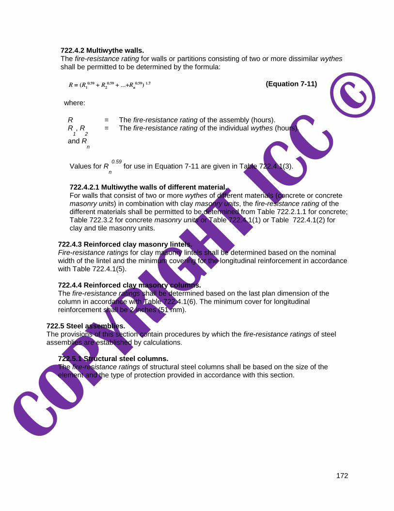
172
722.4.2 Multiwythe walls. The fire-resistance rating for walls or partitions consisting of two or more dissimilar wythes shall be permitted to be determined by the formula:
(Equation 7-11)
where:
R = The fire-resistance rating of the assembly (hours). R
1, R
2
and Rn
= The fire-resistance rating of the individual wythes (hours).
Values for Rn
0.59 for use in Equation 7-11 are given in Table 722.4.1(3).
722.4.2.1 Multiwythe walls of different material. For walls that consist of two or more wythes of different materials (concrete or concrete masonry units) in combination with clay masonry units, the fire-resistance rating of the different materials shall be permitted to be determined from Table 722.2.1.1 for concrete; Table 722.3.2 for concrete masonry units or Table 722.4.1(1) or Table 722.4.1(2) for clay and tile masonry units.
722.4.3 Reinforced clay masonry lintels. Fire-resistance ratings for clay masonry lintels shall be determined based on the nominal width of the lintel and the minimum covering for the longitudinal reinforcement in accordance with Table 722.4.1(5).
722.4.4 Reinforced clay masonry columns. The fire-resistance ratings shall be determined based on the last plan dimension of the column in accordance with Table 722.4.1(6). The minimum cover for longitudinal reinforcement shall be 2 inches (51 mm).
722.5 Steel assemblies. The provisions of this section contain procedures by which the fire-resistance ratings of steel assemblies are established by calculations.
722.5.1 Structural steel columns. The fire-resistance ratings of structural steel columns shall be based on the size of the element and the type of protection provided in accordance with this section.

173
FIGURE 722.5.1(1) DETERMINATION OF THE HEATED
PERIMETER OF STRUCTURAL STEEL COLUMN

174
For SI:1 inch = 25.4 mm, 1 foot = 305 mm. 1. Structural steel column, either wide flange or tubular shapes. 2. Type X gypsum board or gypsum panel products in accordance with ASTM C1177, C1178, C1278, C1396 or
C1658. The total thickness of gypsum board or gypsum panel products calculated as h in Section 722.5.1.2 shall be applied vertically to an individual column using one of the following methods: 1. As a single layer without horizontal joints. 2. As multiple layers with horizontal joints not permitted in any layer. 3. As multiple layers with horizontal joints staggered not less than 12 inches vertically between layers and not
less than 8 feet vertically in any single layer. The total required thickness of gypsum board or gypsum panel products shall be determined on the basis of the specified fire-resistance rating and the weight-to-heated-perimeter ratio (W/D) of the column. For fire-resistance ratings of 2 hours or less, one of the required layers of gypsum board or gypsum panel product may be applied to the exterior of the sheet steel column covers with 1-inch long Type S screws spaced 1 inch from the wallboard edge and 8 inches on center. For such
installations, 0.0149-inch minimum thickness galvanized steel corner beads with 11/2-inch legs shall be
attached to the wallboard with Type S screws spaced 12 inches on center. 3. For fire-resistance ratings of 3 hours or less, the column covers shall be fabricated from 0.0239-inch minimum
thickness galvanized or stainless steel. For 4-hour fire-resistance ratings, the column covers shall be fabricated from 0.0239-inch minimum thickness stainless steel. The column covers shall be erected with the Snap Lock or Pittsburgh joint details. For fire-resistance ratings of 2 hours or less, column covers fabricated from 0.0269-inch minimum thickness galvanized or stainless steel shall be permitted to be erected with lap joints. The lap joints shall be permitted to be located anywhere around the perimeter of the column cover. The lap joints shall be
secured with 1/2-inch-long No. 8 sheet metal screws spaced 12 inches on center. The column covers shall be
provided with a minimum expansion clearance of 1/8 inch per linear foot between the ends of the cover and any
restraining construction.
FIGURE 722.5.1(2) GYPSUM-PROTECTED STRUCTURAL
STEEL COLUMNS WITH SHEET STEEL COLUMN COVERS

175
For SI:1 inch = 25.4 mm, 1 foot = -305 mm. 1. Structural steel column, either wide flange or tubular shapes.
2. 15/8-inch deep studs fabricated from 0.0179-inch minimum thickness galvanized steel with 1
5/16
or 17/16
-inch
legs. The length of the steel studs shall be 1/2 inch less than the height of the assembly.
3. Type X gypsum board or gypsum panel products in accordance with ASTM C1177, C1178, C1278, C1396 or C1658. The total thickness of gypsum board or gypsum panel products calculated as h in Section 722.5.1.2 shall be applied vertically to an individual column using one of the following methods: 1. As a single layer without horizontal joints. 2. As multiple layers with horizontal joints not permitted in any layer. 3. As multiple layers with horizontal joints staggered not less than 12
inches vertically between layers and not less than 8 feet vertically in any single layer. The total required thickness of gypsum board or gypsum panel products shall be determined on the basis of the specified fire-resistance rating and the weight-to-heated-perimeter ratio (W/D) of the column.
4. Galvanized 0.0149-inch minimum thickness steel corner beads with 11/2-inch legs attached to the gypsum board
or gypsum panel products with 1-inch-long Type S screws spaced 12 inches on center. 5. No. 18 SWG steel tie wires spaced 24 inches on center. 6. Sheet metal angles with 2-inch legs fabricated from 0.0221-inch minimum thickness galvanized steel. 7. Type S screws, 1 inch long, shall be used for attaching the first layer of gypsum board or gypsum panel product
to the steel studs and the third layer to the sheet metal angles at 24 inches on center. Type S screws 13/4 inches
long shall be used for attaching the second layer of gypsum board or gypsum panel product to the steel studs
and the fourth layer to the sheet metal angles at 12 inches on center. Type S screws 21/4 inches long shall be
used for attaching the third layer of gypsum board or gypsum panel product to the steel studs at 12 inches on center.
FIGURE 722.5.1(3) GYPSUM-PROTECTED STRUCTURAL STEEL COLUMNS
WITH STEEL STUD/SCREW ATTACHMENT SYSTEM

176
For SI:1 inch = 25.4 mm, 1 pound per linear foot/inch = 0.059 kg/m/mm.
a. The W/D ratios for typical wide flange columns are listed in Table 722.5.1(1). For other column shapes, the W/D
ratios shall be determined in accordance with Section 722.5.1.1.
FIGURE 722.5.1(4) FIRE RESISTANCE OF STRUCTURAL
STEEL COLUMNS PROTECTED WITH VARIOUS THICKNESSES OF TYPE X GYPSUM WALLBOARD
FIGURE 722.5.1(5) WIDE FLANGE STRUCTURAL STEEL COLUMNS WITH
SPRAYED FIRE-RESISTANT MATERIALS
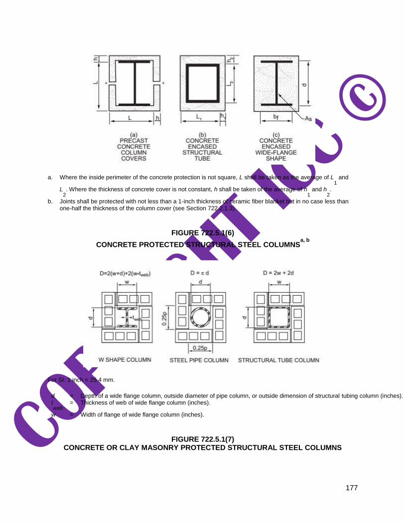
177
a. Where the inside perimeter of the concrete protection is not square, L shall be taken as the average of L
1 and
L2. Where the thickness of concrete cover is not constant, h shall be taken of the average of h
1 and h
2.
b. Joints shall be protected with not less than a 1-inch thickness of ceramic fiber blanket but in no case less than one-half the thickness of the column cover (see Section 722.2.1.3).
FIGURE 722.5.1(6)
CONCRETE PROTECTED STRUCTURAL STEEL COLUMNSa, b
For SI: 1 inch = 25.4 mm.
d = Depth of a wide flange column, outside diameter of pipe column, or outside dimension of structural tubing column (inches). tweb
= Thickness of web of wide flange column (inches).
w = Width of flange of wide flange column (inches).
FIGURE 722.5.1(7) CONCRETE OR CLAY MASONRY PROTECTED STRUCTURAL STEEL COLUMNS

178
TABLE 722.5.1(1) W/D RATIOS FOR STEEL COLUMNS
STRUCTURAL SHAPE CONTOUR PROFILE BOX PROFILE
W14 × 233 2.55 3.65
× 211 2.32 3.35
× 193 2.14 3.09
× 176 1.96 2.85
× 159 1.78 2.60
× 145 1.64 2.39
× 132 1.56 2.25
× 120 1.42 2.06
× 109 1.29 1.88
× 99 1.18 1.72
× 90 1.08 1.58
× 82 1.23 1.68
× 74 1.12 1.53
× 68 1.04 1.41
× 61 0.928 1.28
× 53 0.915 1.21
× 48 0.835 1.10
× 43 0.752 0.99
W12 × 190 2.50 3.51
× 170 2.26 3.20
× 152 2.04 2.90
× 136 1.86 2.63
× 120 1.65 2.36
× 106 1.47 2.11
× 96 1.34 1.93
× 87 1.22 1.76
× 79 1.11 1.61
× 72 1.02 1.48
× 65 0.925 1.35
× 58 0.925 1.31
× 53 0.855 1.20
× 50 0.909 1.23
× 45 0.829 1.12
× 40 0.734 1.00
W10 × 112 1.81 2.57
× 100 1.64 2.33
× 88 1.45 2.08
× 77 1.28 1.85
× 68 1.15 1.66
× 60 1.01 1.48
× 54 0.922 1.34
× 49 0.84 1.23
× 45 0.888 1.24
× 39 0.78 1.09
× 33 0.661 0.93
(continued)

179
TABLE 722.5.1(1)—continued W/D RATIOS FOR STEEL COLUMNS
STRUCTURAL SHAPE CONTOUR PROFILE BOX PROFILE
W8 × 67 1.37 1.94
× 58 1.20 1.71
× 48 1.00 1.44
× 40 0.849 1.23
× 35 0.749 1.08
× 31 0.665 0.97
× 28 0.688 0.96
× 24 0.591 0.83
× 21 0.577 0.77
× 18 0.499 0.67
W6 ×25 0.696 1.00
× 20 0.563 0.82
× 16 0.584 0.78
× 15 0.431 0.63
× 12 0.448 0.60
× 9 0.338 0.46
W5 ×19 0.644 0.93
× 16 0.55 0.80
W4 ×13 0.556 0.79
For SI: 1 pound per linear foot per inch = 0.059 kg/m/mm.
TABLE 722.5.1(2) PROPERTIES OF CONCRETE
PROPERTY NORMAL-WEIGHT
CONCRETE STRUCTURAL LIGHTWEIGHT
CONCRETE
Thermal conductivity (kc) 0.95 Btu/hr × ft × °F 0.35 Btu/hr × ft × °F
Specific heat (cc) 0.20 Btu/lb °F 0.20 Btu/lb °F
Density (Pc)
145 lb/ft3 110 lb/ft
3
Equilibrium (free) moisture content (m) by volume
4% 5%
For SI: 1 inch = 25.4 mm, 1 foot = 304.8 mm, 1 lb/ft3 = 16.0185 kg/m
3, Btu/hr · ft · °F = 1.731 W/(m · K).
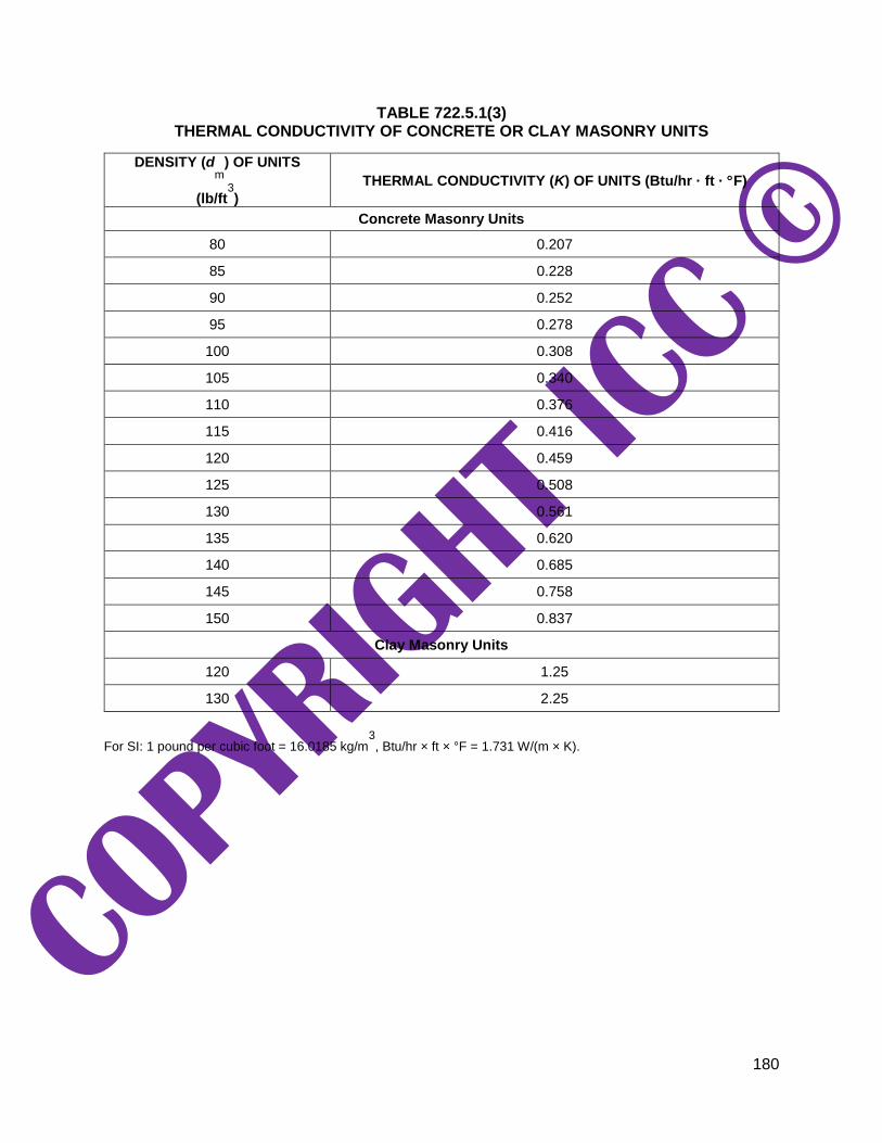
180
TABLE 722.5.1(3) THERMAL CONDUCTIVITY OF CONCRETE OR CLAY MASONRY UNITS
DENSITY (dm
) OF UNITS
(lb/ft3)
THERMAL CONDUCTIVITY (K) OF UNITS (Btu/hr · ft · F)
Concrete Masonry Units
80 0.207
85 0.228
90 0.252
95 0.278
100 0.308
105 0.340
110 0.376
115 0.416
120 0.459
125 0.508
130 0.561
135 0.620
140 0.685
145 0.758
150 0.837
Clay Masonry Units
120 1.25
130 2.25
For SI: 1 pound per cubic foot = 16.0185 kg/m3, Btu/hr × ft × °F = 1.731 W/(m × K).

181
TABLE 722.5.1(4) WEIGHT-TO-HEATED-PERIMETER RATIOS (W/D) FOR TYPICAL WIDE FLANGE BEAM AND GIRDER SHAPES
STRUCTURAL SHAPE CONTOUR PROFILE BOX PROFILE
W36 × 300 2.50 3.33
× 280 2.35 3.12
× 260 2.18 2.92
× 245 2.08 2.76
× 230 1.95 2.61
× 210 1.96 2.45
× 194 1.81 2.28
× 182 1.72 2.15
× 170 1.60 2.01
× 160 1.51 1.90
× 150 1.43 1.79
× 135 1.29 1.63
W33 × 241 2.13 2.86
× 221 1.97 2.64
× 201 1.79 2.42
× 152 1.53 1.94
× 141 1.43 1.80
× 130 1.32 1.67
× 118 1.21 1.53
W30 × 211 2.01 2.74
× 191 1.85 2.50
× 173 1.66 2.28
× 132 1.47 1.85
× 124 1.39 1.75
× 116 1.30 1.65
× 108 1.21 1.54
× 99 1.12 1.42
W27 × 178 1.87 2.55
× 161 1.70 2.33
× 146 1.55 2.12
× 114 1.39 1.76
× 102 1.24 1.59
× 94 1.15 1.47
× 84 1.03 1.33
W24 × 162 1.88 2.57
× 146 1.70 2.34
× 131 1.54 2.12
× 117 1.38 1.91
× 104 1.24 1.71
× 94 1.28 1.63
× 84 1.15 1.47
× 76 1.05 1.34
(continued)
TABLE 722.5.1(4)—continued

182
WEIGHT-TO-HEATED-PERIMETER RATIOS (W/D) FOR TYPICAL WIDE FLANGE BEAM AND GIRDER SHAPES
STRUCTURAL SHAPE CONTOUR PROFILE BOX PROFILE
W24 × 68 0.942 1.21
× 62 0.934 1.14
× 55 0.828 1.02
W21 × 147 1.87 2.60
× 132 1.68 2.35
× 122 1.57 2.19
× 111 1.43 2.01
× 101 1.30 1.84
× 93 1.40 1.80
× 83 1.26 1.62
× 73 1.11 1.44
× 68 1.04 1.35
W21 × 62 0.952 1.23
× 57 0.952 1.17
× 50 0.838 1.04
× 44 0.746 0.92
W18 × 119 1.72 2.42
× 106 1.55 2.18
× 97 1.42 2.01
× 86 1.27 1.80
× 76 1.13 1.60
× 71 1.22 1.59
× 65 1.13 1.47
× 60 1.04 1.36
× 55 0.963 1.26
× 50 0.88 1.15
× 46 0.878 1.09
× 40 0.768 0.96
× 35 0.672 0.85
W16 × 100 1.59 2.25
× 89 1.43 2.03
× 77 1.25 1.78
× 67 1.09 1.56
× 57 1.09 1.43
× 50 0.962 1.26
× 45 0.870 1.15
× 40 0.780 1.03
× 36 0.702 0.93
× 31 0.661 0.83
× 26 0.558 0.70
W14 × 132 1.89 3.00
× 120 1.71 2.75
× 109 1.57 2.52
(continued)
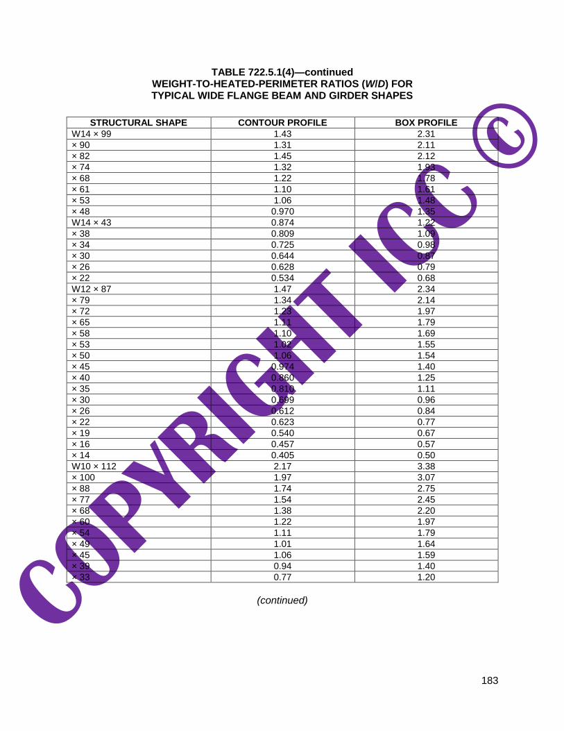
183
TABLE 722.5.1(4)—continued WEIGHT-TO-HEATED-PERIMETER RATIOS (W/D) FOR TYPICAL WIDE FLANGE BEAM AND GIRDER SHAPES
STRUCTURAL SHAPE CONTOUR PROFILE BOX PROFILE
W14 × 99 1.43 2.31
× 90 1.31 2.11
× 82 1.45 2.12
× 74 1.32 1.93
× 68 1.22 1.78
× 61 1.10 1.61
× 53 1.06 1.48
× 48 0.970 1.35
W14 × 43 0.874 1.22
× 38 0.809 1.09
× 34 0.725 0.98
× 30 0.644 0.87
× 26 0.628 0.79
× 22 0.534 0.68
W12 × 87 1.47 2.34
× 79 1.34 2.14
× 72 1.23 1.97
× 65 1.11 1.79
× 58 1.10 1.69
× 53 1.02 1.55
× 50 1.06 1.54
× 45 0.974 1.40
× 40 0.860 1.25
× 35 0.810 1.11
× 30 0.699 0.96
× 26 0.612 0.84
× 22 0.623 0.77
× 19 0.540 0.67
× 16 0.457 0.57
× 14 0.405 0.50
W10 × 112 2.17 3.38
× 100 1.97 3.07
× 88 1.74 2.75
× 77 1.54 2.45
× 68 1.38 2.20
× 60 1.22 1.97
× 54 1.11 1.79
× 49 1.01 1.64
× 45 1.06 1.59
× 39 0.94 1.40
× 33 0.77 1.20
(continued)

184
TABLE 722.5.1(4)—continued WEIGHT-TO-HEATED-PERIMETER RATIOS (W/D) FOR TYPICAL WIDE FLANGE BEAM AND GIRDER SHAPES
STRUCTURAL SHAPE CONTOUR PROFILE BOX PROFILE
W10 × 30 0.806 1.12
× 26 0.708 0.98
× 22 0.606 0.84
× 19 0.607 0.78
× 17 0.543 0.70
× 15 0.484 0.63
× 12 0.392 0.51
W8 × 67 1.65 2.55
× 58 1.44 2.26
× 48 1.21 1.91
× 40 1.03 1.63
× 35 0.907 1.44
× 31 0.803 1.29
× 28 0.819 1.24
× 24 0.704 1.07
× 21 0.675 0.96
× 18 0.583 0.84
× 15 0.551 0.74
× 13 0.483 0.65
× 10 0.375 0.51
W6 × 25 0.839 1.33
× 20 0.678 1.09
× 16 0.684 0.96
× 15 0.521 0.83
× 12 0.526 0.75
× 9 0.398 0.57
W5 × 19 0.776 1.24
× 16 0.664 1.07
W4 × 13 0.670 1.05
For SI: 1 pound per linear foot per inch = 0.059 kg/m/mm.
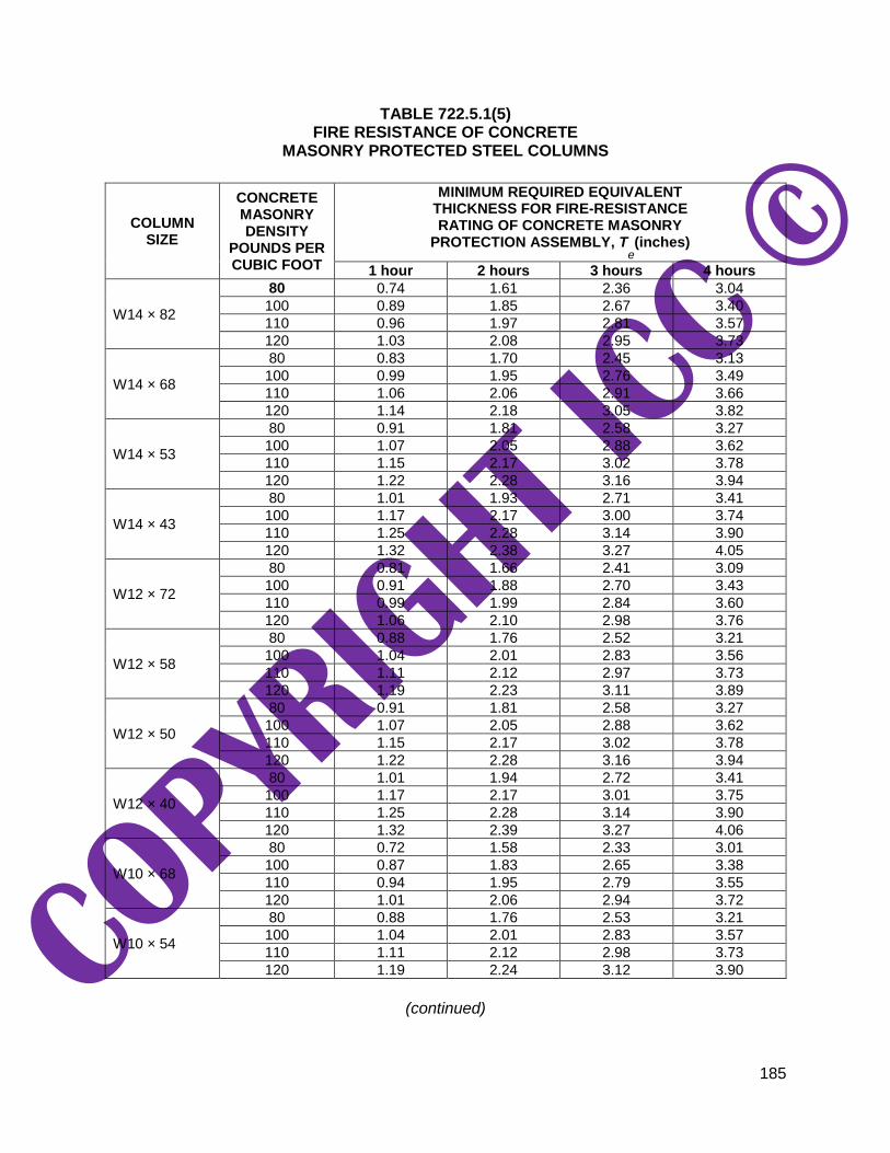
185
TABLE 722.5.1(5) FIRE RESISTANCE OF CONCRETE
MASONRY PROTECTED STEEL COLUMNS
COLUMN SIZE
CONCRETE MASONRY DENSITY
POUNDS PER CUBIC FOOT
MINIMUM REQUIRED EQUIVALENT THICKNESS FOR FIRE-RESISTANCE RATING OF CONCRETE MASONRY
PROTECTION ASSEMBLY, Te(inches)
1 hour 2 hours 3 hours 4 hours
W14 × 82
80 0.74 1.61 2.36 3.04
100 0.89 1.85 2.67 3.40
110 0.96 1.97 2.81 3.57
120 1.03 2.08 2.95 3.73
W14 × 68
80 0.83 1.70 2.45 3.13
100 0.99 1.95 2.76 3.49
110 1.06 2.06 2.91 3.66
120 1.14 2.18 3.05 3.82
W14 × 53
80 0.91 1.81 2.58 3.27
100 1.07 2.05 2.88 3.62
110 1.15 2.17 3.02 3.78
120 1.22 2.28 3.16 3.94
W14 × 43
80 1.01 1.93 2.71 3.41
100 1.17 2.17 3.00 3.74
110 1.25 2.28 3.14 3.90
120 1.32 2.38 3.27 4.05
W12 × 72
80 0.81 1.66 2.41 3.09
100 0.91 1.88 2.70 3.43
110 0.99 1.99 2.84 3.60
120 1.06 2.10 2.98 3.76
W12 × 58
80 0.88 1.76 2.52 3.21
100 1.04 2.01 2.83 3.56
110 1.11 2.12 2.97 3.73
120 1.19 2.23 3.11 3.89
W12 × 50
80 0.91 1.81 2.58 3.27
100 1.07 2.05 2.88 3.62
110 1.15 2.17 3.02 3.78
120 1.22 2.28 3.16 3.94
W12 × 40
80 1.01 1.94 2.72 3.41
100 1.17 2.17 3.01 3.75
110 1.25 2.28 3.14 3.90
120 1.32 2.39 3.27 4.06
W10 × 68
80 0.72 1.58 2.33 3.01
100 0.87 1.83 2.65 3.38
110 0.94 1.95 2.79 3.55
120 1.01 2.06 2.94 3.72
W10 × 54
80 0.88 1.76 2.53 3.21
100 1.04 2.01 2.83 3.57
110 1.11 2.12 2.98 3.73
120 1.19 2.24 3.12 3.90
(continued)

186
TABLE 722.5.1(5)—continued FIRE RESISTANCE OF CONCRETE
MASONRY PROTECTED STEEL COLUMNS
COLUMN SIZE
CONCRETE MASONRY DENSITY
POUNDS PER CUBIC FOOT
MINIMUM REQUIRED EQUIVALENT THICKNESS FOR FIRE-RESISTANCE RATING OF CONCRETE MASONRY
PROTECTION ASSEMBLY, Te(inches)
1 hour 2 hours 3 hours 4 hours
W10 × 45
80 0.92 1.83 2.60 3.30
100 1.08 2.07 2.90 3.64
110 1.16 2.18 3.04 3.80
120 1.23 2.29 3.18 3.96
W10 × 33
80 1.06 2.00 2.79 3.49
100 1.22 2.23 3.07 3.80
110 1.30 2.34 3.20 3.96
120 1.37 2.44 3.33 4.12
W8 × 40
80 0.94 1.85 2.63 3.33
100 1.10 2.10 2.93 3.67
110 1.18 2.21 3.07 3.83
120 1.25 2.32 3.20 3.99
W8 × 31
80 1.06 2.00 2.78 3.49
100 1.22 2.23 3.07 3.81
110 1.29 2.33 3.20 3.97
120 1.36 2.44 3.33 4.12
W8 × 24
80 1.14 2.09 2.89 3.59
100 1.29 2.31 3.16 3.90
110 1.36 2.42 3.28 4.05
120 1.43 2.52 3.41 4.20
W8 × 18
80 1.22 2.20 3.01 3.72
100 1.36 2.40 3.25 4.01
110 1.42 2.50 3.37 4.14
120 1.48 2.59 3.49 4.28
8 × 8 × 1/2 wall
thickness
80 0.77 1.66 2.44 3.13
100 0.92 1.91 2.75 3.49
110 1.00 2.02 2.89 3.66
120 1.07 2.14 3.03 3.82
8 × 8 × 3/8 wall
thickness
80 0.91 1.84 2.63 3.33
100 1.07 2.08 2.92 3.67
110 1.14 2.19 3.06 3.83
120 1.21 2.29 3.19 3.98
8 × 8 × 1/4 wall
thickness
80 1.10 2.06 2.86 3.57
100 1.25 2.28 3.13 3.87
110 1.32 2.38 3.25 4.02
120 1.39 2.48 3.38 4.17
6 × 6 × 1/2 wall
thickness
80 0.82 1.75 2.54 3.25
100 0.98 1.99 2.84 3.59
110 1.05 2.10 2.98 3.75
120 1.12 2.21 3.11 3.91
(continued)

187
TABLE 722.5.1(5)—continued FIRE RESISTANCE OF CONCRETE
MASONRY PROTECTED STEEL COLUMNS
COLUMN SIZE
CONCRETE MASONRY DENSITY
POUNDS PER CUBIC FOOT
MINIMUM REQUIRED EQUIVALENT THICKNESS FOR FIRE-RESISTANCE RATING OF CONCRETE MASONRY
PROTECTION ASSEMBLY, Te(inches)
1 hour 2 hours 3 hours 4 hours
6 × 6 × 3/8 wall
thickness
80 0.96 1.91 2.71 3.42
100 1.12 2.14 3.00 3.75
110 1.19 2.25 3.13 3.90
120 1.26 2.35 3.26 4.05
6 × 6 × 1/4 wall
thickness
80 1.14 2.11 2.92 3.63
100 1.29 2.32 3.18 3.93
110 1.36 2.43 3.30 4.08
120 1.42 2.52 3.43 4.22
4 × 4 × 1/2 wall
thickness
80 0.93 1.90 2.71 3.43
100 1.08 2.13 2.99 3.76
110 1.16 2.24 3.13 3.91
120 1.22 2.34 3.26 4.06
4 × 4 × 3/8 wall
thickness
80 1.05 2.03 2.84 3.57
100 1.20 2.25 3.11 3.88
110 1.27 2.35 3.24 4.02
120 1.34 2.45 3.37 4.17
4 × 4 × 1/4 wall
thickness
80 1.21 2.20 3.01 3.73
100 1.35 2.40 3.26 4.02
110 1.41 2.50 3.38 4.16
120 1.48 2.59 3.50 4.30
6 double extra strong 0.864 wall thickness
80 0.59 1.46 2.23 2.92
100 0.73 1.71 2.54 3.29
110 0.80 1.82 2.69 3.47
120 0.86 1.93 2.83 3.63
6 extra strong 0.432 wall thickness
80 0.94 1.90 2.70 3.42
100 1.10 2.13 2.98 3.74
110 1.17 2.22 3.11 3.89
120 1.24 2.34 3.24 4.04
6 standard 0.280 wall thickness
80 1.14 2.12 2.93 3.64
100 1.29 2.33 3.19 3.94
110 1.36 2.43 3.31 4.08
120 1.42 2.53 3.43 4.22
5 double extra strong 0.750 wall thickness
80 0.70 1.61 2.40 3.12
100 0.85 1.86 2.71 3.47
110 0.91 1.97 2.85 3.63
120 0.98 2.02 2.99 3.79
5 extra strong 0.375 wall thickness
80 1.04 2.01 2.83 3.54
100 1.19 2.23 3.09 3.85
110 1.26 2.34 3.22 4.00
20 1.32 2.44 3.34 4.14
(continued)
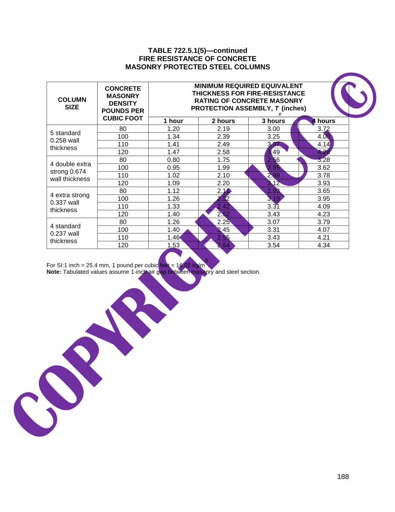
188
TABLE 722.5.1(5)—continued FIRE RESISTANCE OF CONCRETE
MASONRY PROTECTED STEEL COLUMNS
COLUMN SIZE
CONCRETE MASONRY DENSITY
POUNDS PER CUBIC FOOT
MINIMUM REQUIRED EQUIVALENT THICKNESS FOR FIRE-RESISTANCE RATING OF CONCRETE MASONRY
PROTECTION ASSEMBLY, Te(inches)
1 hour 2 hours 3 hours 4 hours
5 standard 0.258 wall thickness
80 1.20 2.19 3.00 3.72
100 1.34 2.39 3.25 4.00
110 1.41 2.49 3.37 4.14
120 1.47 2.58 3.49 4.28
4 double extra strong 0.674 wall thickness
80 0.80 1.75 2.56 3.28
100 0.95 1.99 2.85 3.62
110 1.02 2.10 2.99 3.78
120 1.09 2.20 3.12 3.93
4 extra strong 0.337 wall thickness
80 1.12 2.11 2.93 3.65
100 1.26 2.32 3.19 3.95
110 1.33 2.42 3.31 4.09
120 1.40 2.52 3.43 4.23
4 standard 0.237 wall thickness
80 1.26 2.25 3.07 3.79
100 1.40 2.45 3.31 4.07
110 1.46 2.55 3.43 4.21
120 1.53 2.64 3.54 4.34
For SI:1 inch = 25.4 mm, 1 pound per cubic feet = 16.02 kg/m3.
Note: Tabulated values assume 1-inch air gap between masonry and steel section.

189
TABLE 722.5.1(6) FIRE RESISTANCE OF CLAY MASONRY PROTECTED STEEL COLUMNS
For SI: 1 inch = 25.4 mm, 1 pound per cubic foot = 16.02 kg/m3.
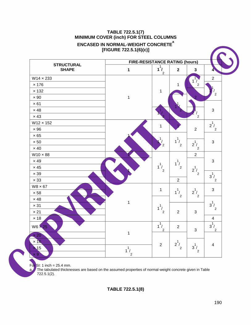
190
TABLE 722.5.1(7) MINIMUM COVER (inch) FOR STEEL COLUMNS
ENCASED IN NORMAL-WEIGHT CONCRETEa
[FIGURE 722.5.1(6)(c)]
STRUCTURAL SHAPE
FIRE-RESISTANCE RATING (hours)
1 11/2 2 3 4
W14 × 233
1
1
1 1
1/2
2
× 176
21/2 × 132
2 × 90
11/2
× 61
3 × 48 1
1/2 2
1/2
× 43
W12 × 152
1
1 1 2
21/2
× 96
× 65
11/2 1
1/2 3 × 50
21/2
× 40
W10 × 88 1
11/2
11/2
2
3 × 49
1 21/2
× 45
× 39 3
1/2
× 33 2
W8 × 67
1
1 1
1/2 2
1/2
3 × 58
× 48
11/2
31/2 × 31
2 3 × 21
× 18 4
W6 × 25
1
11/2 2
3 3
1/2
× 20
2 21/2 4
× 16
31/2 × 15
11/2
× 9
For SI: 1 inch = 25.4 mm. a. The tabulated thicknesses are based on the assumed properties of normal-weight concrete given in Table
722.5.1(2).
TABLE 722.5.1(8)

191
MINIMUM COVER (inch) FOR STEEL COLUMNS
ENCASED IN STRUCTURAL LIGHTWEIGHT CONCRETEa
[FIGURE 722.5.1(6)(c)]
STRUCTURAL SHAPE
FIRE-RESISTANCE RATING (HOURS)
1 11/2 2 3 4
W14 × 233
1 1
1
1 1
1/2
× 193
11/2 × 74 2
× 61
21/2
× 43 11/2 2
W12 × 65
1 1
1 1
1/2 2
× 53
2 21/2
× 40 11/2
W10 × 112
1 1
1 1
1/2 2
× 88
× 60
2 21/2
× 33 11/2
W8 × 35
1
1
11/2
2 2
1/2
× 28
3 × 24
21/2
× 18 11/2
For SI: 1 inch = 25.4 mm. a. The tabulated thicknesses are based on the assumed properties of structural lightweight concrete given in Table
722.5.1(2).

192
TABLE 722.5.1(9) MINIMUM COVER (inch) FOR STEEL COLUMNS
IN NORMAL-WEIGHT PRECAST COVERSa
[FIGURE 722.5.1(6)(a)]
For SI: 1 inch = 25.4 mm. a. The tabulated thicknesses are based on the assumed properties of normal-weight concrete given in Table
722.5.1(2).

193
TABLE 722.5.1(10) MINIMUM COVER (inch) FOR STEEL COLUMNS
IN STRUCTURAL LIGHTWEIGHT PRECAST COVERSa
[FIGURE 722.5.1(6)(a)]
For SI: 1 inch = 25.4 mm. a. The tabulated thicknesses are based on the assumed properties of structural lightweight concrete given in Table
722.5.1(2).

194
722.5.1.1 General. These procedures establish a basis for determining the fire resistance of column assemblies as a function of the thickness of fire-resistant material and, the weight, W, and heated perimeter, D, of structural steel columns. As used in these sections, W is the average weight of a structural steel column in pounds per linear foot. The heated perimeter, D, is the inside perimeter of the fire-resistant material in inches as illustrated in Figure 722.5.1(1).
722.5.1.1.1 Nonload-bearing protection. The application of these procedures shall be limited to column assemblies in which the fire-resistant material is not designed to carry any of the load acting on the column.
722.5.1.1.2 Embedments. In the absence of substantiating fire-endurance test results, ducts, conduit, piping, and similar mechanical, electrical, and plumbing installations shall not be embedded in any required fire-resistant materials.
722.5.1.1.3 Weight-to-perimeter ratio. Table 722.5.1(1) contains weight-to-heated-perimeter ratios (W/D) for both contour and box fire-resistant profiles, for the wide flange shapes most often used as columns. For different fire-resistant protection profiles or column cross sections, the weight-to-heated-perimeter ratios (W/D) shall be determined in accordance with the definitions given in this section.
722.5.1.2 Gypsum wallboard protection. The fire resistance of structural steel columns with weight-to-heated-perimeter ratios (W/D) less than or equal to 3.65 and that are protected with Type X gypsum wallboard shall be permitted to be determined from the following expression:
(Equation 7-12)
where:
R = Fire resistance (minutes). h = Total thickness of gypsum wallboard (inches). D = Heated perimeter of the structural steel column
(inches).
W’ = Total weight of the structural steel column and gypsum wallboard protection (pounds per linear foot).
W’ = W + 50hD/144.
722.5.1.2.1 Attachment. The gypsum board or gypsum panel products shall be supported as illustrated in either Figure 722.5.1(2) for fire-resistance ratings of 4 hours or less, or Figure 722.5.1(3) for fire-resistance ratings of 3 hours or less.

195
722.5.1.2.2 Gypsum wallboard equivalent to concrete. The determination of the fire resistance of structural steel columns from Figure 722.5.1(4) is permitted for various thicknesses of gypsum wallboard as a function of the weight-to-heated-perimeter ratio (W/D) of the column. For structural steel columns with weight-to-heated-perimeter ratios (W/D) greater than 3.65, the thickness of gypsum wallboard required for specified fire-resistance ratings shall be the same as the thickness determined for a W14 × 233 wide flange shape.
722.5.1.3 Sprayed fire-resistant materials. The fire resistance of wide-flange structural steel columns protected with sprayed fire-resistant materials, as illustrated in Figure 722.5.1(5), shall be permitted to be determined from the following expression:
(Equation 7-13)
where:
R = Fire resistance (minutes). h = Thickness of sprayed fire-resistant material (inches). D = Heated perimeter of the structural steel column
(inches). C
1 and
C2
= Material-dependent constants.
W = Weight of structural steel columns (pounds per linear foot).
The fire resistance of structural steel columns protected with intumescent or mastic
fire-resistant coatings shall be determined on the basis of fire-resistance tests in accordance with Section 703.2.
722.5.1.3.1 Material-dependent constants. The material-dependent constants, C
1 and C
2, shall be determined for specific fire-
resistant materials on the basis of standard fire endurance tests in accordance with Section 703.2. Unless evidence is submitted to the building official substantiating a broader application, this expression shall be limited to determining the fire resistance of structural steel columns with weight-to-heated-perimeter ratios (W/D) between the largest and smallest columns for which standard fire-resistance test results are available.
722.5.1.3.2 Identification. Sprayed fire-resistant materials shall be identified by density and thickness required for a given fire-resistance rating.
722.5.1.4 Concrete-protected columns. The fire resistance of structural steel columns protected with concrete, as illustrated in Figure 722.5.1(6) illustrations (a) and (b), shall be permitted to be determined from the following expression:

196
(Equation 7-14)
where:
R
o = 10 (W/D)
0.7 + 17 (h
1.6/k
c
0.2) × [1 + 26 {H/p
cc
ch (L +
h)}0.8
] As used in these expressions: R = Fire endurance at equilibrium moisture conditions
(minutes). R
o = Fire endurance at zero moisture content (minutes).
m = Equilibrium moisture content of the concrete by volume (percent).
W = Average weight of the structural steel column (pounds per linear foot).
D = Heated perimeter of the structural steel column (inches).
h = Thickness of the concrete cover (inches). k
c = Ambient temperature thermal conductivity of the
concrete (Btu/hr ft F). H = Ambient temperature thermal capacity of the steel
column = 0.11W (Btu/ ft °F). p
c = Concrete density (pounds per cubic foot).
cc = Ambient temperature specific heat of concrete (Btu/lb
°F).
L = Interior dimension of one side of a square concrete box protection (inches).
722.5.1.4.1 Reentrant space filled. For wide-flange structural steel columns completely encased in concrete with all reentrant spaces filled Figure 722.5.1(6), illustration (c), the thermal capacity of the concrete within the reentrant spaces shall be permitted to be added to the thermal capacity of the steel column, as follows:
(Equation 7-15)
where:
b
f = Flange width of the structural steel column
(inches). d = Depth of the structural steel column
(inches). A
s = Cross-sectional area of the steel column
(square inches).
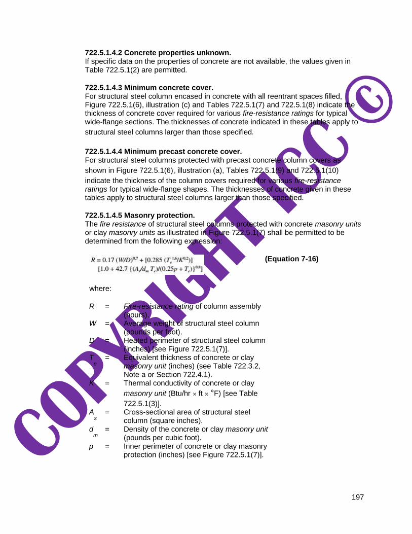
197
722.5.1.4.2 Concrete properties unknown. If specific data on the properties of concrete are not available, the values given in Table 722.5.1(2) are permitted.
722.5.1.4.3 Minimum concrete cover. For structural steel column encased in concrete with all reentrant spaces filled, Figure 722.5.1(6), illustration (c) and Tables 722.5.1(7) and 722.5.1(8) indicate the thickness of concrete cover required for various fire-resistance ratings for typical wide-flange sections. The thicknesses of concrete indicated in these tables apply to
structural steel columns larger than those specified.
722.5.1.4.4 Minimum precast concrete cover. For structural steel columns protected with precast concrete column covers as
shown in Figure 722.5.1(6), illustration (a), Tables 722.5.1(9) and 722.5.1(10)
indicate the thickness of the column covers required for various fire-resistance ratings for typical wide-flange shapes. The thicknesses of concrete given in these tables apply to structural steel columns larger than those specified.
722.5.1.4.5 Masonry protection. The fire resistance of structural steel columns protected with concrete masonry units or clay masonry units as illustrated in Figure 722.5.1(7) shall be permitted to be determined from the following expression:
(Equation 7-16)
where:
R = Fire-resistance rating of column assembly
(hours). W = Average weight of structural steel column
(pounds per foot). D = Heated perimeter of structural steel column
(inches) [see Figure 722.5.1(7)]. T
e = Equivalent thickness of concrete or clay
masonry unit (inches) (see Table 722.3.2, Note a or Section 722.4.1).
K = Thermal conductivity of concrete or clay
masonry unit (Btu/hr × ft × °F) [see Table
722.5.1(3)]. A
s = Cross-sectional area of structural steel
column (square inches). d
m = Density of the concrete or clay masonry unit
(pounds per cubic foot). p = Inner perimeter of concrete or clay masonry
protection (inches) [see Figure 722.5.1(7)].

198
722.5.1.4.6 Equivalent concrete masonry thickness. For structural steel columns protected with concrete masonry, Table 722.5.1(5) gives the equivalent thickness of concrete masonry required for various fire-resistance ratings for typical column shapes. For structural steel columns protected with clay masonry, Table 722.5.1(6) gives the equivalent thickness of concrete masonry required for various fire-resistance ratings for typical column shapes.
722.5.2 Structural steel beams and girders. The fire-resistance ratings of structural steel beams and girders shall be based on the size of the element and the type of protection provided in accordance with this section.
FIGURE 722.5.2 DETERMINATION OF THE HEATED PERIMETER OF
STRUCTURAL STEEL BEAMS AND GIRDERS
722.5.2.1 Determination of fire resistance. These procedures establish a basis for determining resistance of structural steel beams and girders that differ in size from that specified in approved fire-resistance-rated assemblies as a function of the thickness of fire-resistant material and the weight (W) and heated perimeter (D) of the beam or girder. As used in these sections, W is the average weight of a structural steel element in pounds per linear foot (plf). The heated perimeter, D, is the inside perimeter of the fire-resistant material in inches as illustrated in Figure 722.5.2.
722.5.2.1.1 Weight-to-heated perimeter. The weight-to-heated-perimeter ratios (W/D), for both contour and box fire-resistant protection profiles, for the wide flange shapes most often used as beams or girders are given in Table 722.5.1(4). For different shapes, the weight-to-heated-perimeter ratios (W/D) shall be determined in accordance with the definitions given in this section.
722.5.2.1.2 Beam and girder substitutions. Except as provided for in Section 722.5.2.2, structural steel beams in approved fire-resistance-rated assemblies shall be considered to be the minimum permissible size. Other beam or girder shapes shall be permitted to be substituted provided that the weight-to-heated-perimeter ratio (W/D) of the substitute beam is equal to or greater than that of the beam specified in the approved assembly.

199
722.5.2.2 Sprayed fire-resistant materials. The provisions in this section apply to structural steel beams and girders protected with sprayed fire-resistant materials. Larger or smaller beam and girder shapes shall be permitted to be substituted for beams specified in approved unrestrained or restrained fire-resistance-rated assemblies, provided that the thickness of the fire-resistant material is adjusted in accordance with the following expression:
(Equation 7-17)
where:
h = Thickness of sprayed fire-resistant material in
inches. W = Weight of the structural steel beam or girder in
pounds per linear foot. D = Heated perimeter of the structural steel beam in
inches.
Subscript 1 refers to the beam and fire-resistant material thickness in the approved
assembly.
Subscript 2 refers to the substitute beam or girder and the required thickness of fire-
resistant material.
The fire resistance of structural steel beams and girders protected with intumescent
or mastic fire-resistant coatings shall be determined on the basis of fire-resistance tests in accordance with Section 703.2.
722.5.2.2.1 Minimum thickness. The use of Equation 7-17 is subject to the following conditions:
1. The weight-to-heated-perimeter ratio for the substitute beam or girder (W2/D2)
shall be not less than 0.37.
2. The thickness of fire protection materials calculated for the substitute beam or
girder (T1) shall be not less than 3/8 inch (9.5 mm).
3. The unrestrained or restrained beam rating shall be not less than 1 hour.
4. Where used to adjust the material thickness for a restrained beam, the use of
this procedure is limited to structural steel sections classified as compact in accordance with AISC 360.

200
722.5.2.3 Structural steel trusses. The fire resistance of structural steel trusses protected with fire-resistant materials sprayed to each of the individual truss elements shall be permitted to be determined in accordance with this section. The thickness of the fire-resistant material shall be determined in accordance with Section 722.5.1.3. The weight-to-heated-perimeter ratio (W/D) of truss elements that can be simultaneously exposed to fire on all sides shall be determined on the same basis as columns, as specified in Section 722.5.1.1. The weight-to-heated-perimeter ratio (W/D) of truss elements that directly support floor or roof assembly shall be determined on the same basis as beams and girders, as specified in Section 722.5.2.1.
The fire resistance of structural steel trusses protected with intumescent or mastic
fire-resistant coatings shall be determined on the basis of fire resistance tests in accordance with Section 703.2.
722.6 Wood assemblies. The provisions of this section contain procedures by which the fire-resistance ratings of wood assemblies are established by calculations.
722.6.1 General. This section contains procedures for calculating the fire-resistance ratings of walls, floor/ceiling and roof/ceiling assemblies based in part on the standard method of testing referenced in Section 703.2.
722.6.1.1 Maximum fire-resistance rating. Fire-resistance ratings calculated for assemblies using the methods in Section 722.6 shall be limited to not more than 1 hour.
722.6.1.2 Dissimilar membranes. Where dissimilar membranes are used on a wall assembly that requires consideration of fire exposure from both sides, the calculation shall be made from the least fire-resistant (weaker) side.
722.6.2 Walls, floors and roofs. These procedures apply to both load-bearing and nonload-bearing assemblies.

201
TABLE 722.6.2(1)
TIME ASSIGNED TO WALLBOARD MEMBRANESa, b, c, d
DESCRIPTION OF FINISH TIMEe
(minutes) 3/8-inch wood structural panel bonded with exterior glue 5
15/32
-inch wood structural panel bonded with exterior glue 10
19/32
-inch wood structural panel bonded with exterior glue 15
3/8-inch gypsum wallboard 10
1/2-inch gypsum wallboard 15
5/8-inch gypsum wallboard 30
1/2-inch Type X gypsum wallboard 25
5/8-inch Type X gypsum wallboard 40
Double 3/8-inch gypsum wallboard 25
1/2-inch +
3/8-inch gypsum wallboard 35
Double 1/2-inch gypsum wallboard 40
For SI: 1 inch = 25.4 mm. a. These values apply only where membranes are installed on framing members that are spaced 16 inches o.c. or
less.
b. Gypsum wallboard installed over framing or furring shall be installed so that all edges are supported, except 5/8-
inch Type X gypsum wallboard shall be permitted to be installed horizontally with the horizontal joints staggered 24 inches each side and unsupported but finished.
c. On wood frame floor/ceiling or roof/ceiling assemblies, gypsum board shall be installed with the long dimension perpendicular to framing members and shall have all joints finished.
d. The membrane on the unexposed side shall not be included in determining the fire resistance of the assembly. Where dissimilar membranes are used on a wall assembly, the calculation shall be made from the least fire-resistant (weaker) side.
e. The time assigned is not a finished rating.

202
TABLE 722.6.2(2)
TIME ASSIGNED FOR CONTRIBUTION OF WOOD FRAME a, b, c
DESCRIPTION TIME ASSIGNED TO FRAME (minutes)
Wood studs 16 inches o.c. 20
Wood floor and roof joists 16 inches o.c. 10
For SI: 1 inch = 25.4 mm. a. This table does not apply to studs or joists spaced more than 16 inches o.c. b. All studs shall be nominal 2 × 4 and all joists shall have a nominal thickness of not less than 2 inches. c. Allowable spans for joists shall be determined in accordance with Sections 2308.4.2.1, 2308.7.1 and 2308.7.2.
TABLE 722.6.2(3)
MEMBRANEa ON EXTERIOR FACE OF WOOD STUD WALLS
SHEATHING PAPER EXTERIOR FINISH
5/8-inch T & G lumber
5/16
-inch exterior glue wood structural
panel 1/2-inch gypsum wallboard
5/8-inch gypsum wallboard
1/2-inch fiberboard
Sheathing paper
Lumber siding
Wood shingles and shakes 1/4-inch fiber-cement lap, panel
or shingle siding 1/4-inch wood structural
panels-exterior type 1/4-inch hardboard
Metal siding
Stucco on metal lath
Masonry veneer
Vinyl siding
None —
3/8-inch exterior-grade wood
structural panels
For SI: 1 inch = 25.4 mm. a. Any combination of sheathing, paper and exterior finish is permitted.

203
TABLE 722.6.2(4)
FLOORING OR ROOFING OVER WOOD FRAMINGa
ASSEMBLY STRUCTURAL
MEMBERS SUBFLOOR OR
ROOF DECK FINISHED FLOORING OR ROOFING
Floor Wood
15/32
-inch wood
structural panels or 11
/16
-inch T & G
softwood
Hardwood or softwood flooring on building paper; resilient flooring; parquet floor; felted-synthetic fiber floor coverings, carpeting, or
ceramic tile on 1/4-inch-thick fiber-cement
underlayment or 3/8-inch-thick panel-type
underlayment; ceramic tile on 11/4-inch
mortar bed.
Roof Wood
15/32
-inch wood
structural panels or 11
/16
-inch T & G
softwood
Finished roofing material with or without insulation
For SI: 1 inch = 25.4 mm. a. This table applies only to wood joist construction. It is not applicable to wood truss construction.
TABLE 722.6.2(5) TIME ASSIGNED FOR ADDITIONAL PROTECTION
DESCRIPTION OF ADDITIONAL PROTECTION FIRE RESISTANCE
(minutes)
Add to the fire-resistance rating of wood stud walls if the spaces between the studs are completely filled with glass fiber mineral wool batts weighing not less than 2 pounds per cubic foot (0.6 pound per square foot of wall surface) or rockwool or slag material wool batts weighing not less than 3.3 pounds per cubic foot (1 pound per square foot of wall surface), or cellulose insulation having a nominal density not less than 2.6 pounds per cubic foot.
15
For SI: 1 pound/cubic foot = 16.0185 kg/m
3.
722.6.2.1 Fire-resistance rating of wood frame assemblies. The fire-resistance rating of a wood frame assembly is equal to the sum of the time assigned to the membrane on the fire-exposed side, the time assigned to the framing members and the time assigned for additional contribution by other protective measures such as insulation. The membrane on the unexposed side shall not be included in determining the fire resistance of the assembly.
722.6.2.2 Time assigned to membranes. Table 722.6.2(1) indicates the time assigned to membranes on the fire-exposed side.

204
722.6.2.3 Exterior walls. For an exterior wall with a fire separation distance greater than 10 feet (3048 mm), the wall is assigned a rating dependent on the interior membrane and the framing as described in Table 722.6.2(1) and Table 722.6.2(2). The membrane on the outside of the nonfire-exposed side of exterior walls with a fire separation distance greater than 10 feet (3048 mm) shall consist of sheathing, sheathing paper and siding as described in Table 722.6.2(3).
722.6.2.4 Floors and roofs. In the case of a floor or roof, the standard test provides only for testing for fire exposure from below. Except as noted in Section 703.2.3, floor or roof assemblies of wood framing shall have an upper membrane consisting of a subfloor and finished floor conforming to Table 722.6.2(4) or any other membrane that has a contribution to fire resistance of not less than 15 minutes in Table 722.6.2(1).
722.6.2.5 Additional protection. Table 722.6.2(5) indicates the time increments to be added to the fire resistance where glass fiber, rockwool, slag mineral wool or cellulose insulation is incorporated in the assembly.
722.6.2.6 Fastening. Fastening of wood frame assemblies and the fastening of membranes to the wood framing members shall be done in accordance with Chapter 23.
722.7 Fire-resistance rating for mass timber. The required fire resistance of mass timber elements in Section 602.4 shall be determined in accordance with Section 703.2. The fire-resistance rating of building elements shall be as required in Tables 601 and 705.5 and as specified elsewhere in this code. The fire-resistance rating of the mass timber elements shall consist of the fire resistance of the unprotected element added to the protection time of the noncombustible protection.
722.7.1 Minimum required protection. Where required by Sections 602.4.1 through 602.4.3, noncombustible protection shall be provided for mass timber building elements in accordance with Table 722.7.1(1). The rating, in minutes, contributed by the noncombustible protection of mass timber building elements, components or assemblies, shall be established in accordance with Section 703.6. The protection contributions indicated in Table 722.7.1(2) shall be deemed to comply with this
requirement where installed and fastened in accordance with Section 722.7.2.
TABLE 722.7.1(1) PROTECTION REQUIRED FROM NONCOMBUSTIBLE COVERING MATERIAL
REQUIRED FIRE-RESISTANCE RATING OF BUILDING ELEMENT PER TABLE 601 AND
TABLE 705.5 (hours)
MINIMUM PROTECTION REQUIRED FROM NONCOMBUSTIBLE PROTECTION (minutes)
1 40
2 80
3 or more 120

205
TABLE 722.7.1(2) PROTECTION PROVIDED BY NONCOMBUSTIBLE COVERING MATERIAL
NONCOMBUSTIBLE PROTECTION PROTECTION CONTRIBUTION (minutes)
1/2-inch Type X gypsum board 25
5/8-inch Type X gypsum board 40
722.7.2 Installation of gypsum board noncombustible protection. Gypsum board complying with Table 722.7.1(2) shall be installed in accordance with this section.
722.7.2.1 Interior surfaces. Layers of Type X gypsum board serving as noncombustible protection for interior surfaces of wall and ceiling assemblies determined in accordance with Table 722.7.1(1) shall be installed in accordance with the following:
1. Each layer shall be attached with Type S drywall screws of sufficient length to
penetrate the mass timber at least 1 inch (25 mm) when driven flush with the paper surface of the gypsum board.
Exception: The third layer, where determined necessary by Section 722.7, shall be permitted to be attached with 1-inch (25 mm) No. 6 Type S drywall screws to furring channels in accordance with AISI S220.
2. Screws for attaching the base layer shall be 12 inches (305 mm) on center in
both directions.
3. Screws for each layer after the base layer shall be 12 inches (305 mm) on center in both directions and offset from the screws of the previous layers by 4 inches (102 mm) in both directions.
4. All panel edges of any layer shall be offset 18 inches (457 mm) from those of the
previous layer.
5. All panel edges shall be attached with screws sized and offset as in Items 1 through 4 and placed at least 1 inch (25 mm) but not more than 2 inches (51 mm) from the panel edge.
6. All panels installed at wall-to-ceiling intersections shall be installed such that
ceiling panels are installed first and the wall panels are installed after the ceiling panel has been installed and is fitted tight to the ceiling panel. Where multiple
layers are required, each layer shall repeat this process.
7. All panels installed at a wall-to-wall intersection shall be installed such that the
panels covering an exterior wall or a wall with a greater fire-resistance rating shall be installed first and the panels covering the other wall shall be fitted tight to

206
the panel covering the first wall. Where multiple layers are required, each layer shall repeat this process.
8. Panel edges of the face layer shall be taped and finished with joint compound.
Fastener heads shall be covered with joint compound.
9. Panel edges protecting mass timber elements adjacent to unprotected mass
timber elements in accordance with Section 602.4.2.2 shall be covered with 11/4-
inch (32 mm) metal corner bead and finished with joint compound.
722.7.2.2 Exterior surfaces. Layers of Type X gypsum board serving as noncombustible protection for the outside of the exterior mass timber walls determined in accordance with Table 722.7.1(1) shall be fastened 12 inches (305 mm) on center each way and 6 inches (152 mm) on center at all joints or ends. All panel edges shall be attached with fasteners located at least 1 inch (25 mm) but not more than 2 inches (51 mm) from the panel edge. Fasteners shall comply with one of the following:
1. Galvanized nails of minimum 12 gage with a 7/16
-inch (11 mm) head of sufficient
length to penetrate the mass timber a minimum of 1 inch (25 mm).
2. Screws that comply with ASTM C1002 (Type S, W or G) of sufficient length to penetrate the mass timber a minimum of 1 inch (25 mm).