fire, smoke & combined dampers
TRANSCRIPT

Construction and Installation Regulations and Guidelines
Department of Planning and Development - TRAKHEESPorts, Customs & Free Zone Corporation
Government of Dubai, United Arab Emirates
FiRE, SmoKE AnD CombinED DAmPERS
Department of Planning and Development - TRAKHEESPorts, Customs & Free Zone Corporation, Government of DubaiP.O. Box 17000Dubai, United Arab EmiratesEmail: [email protected] Website: www.trakhees.ae
Prepared & issued by
Department of Planning and Development - TRAKHEESPorts, Customs & Free Zone Corporation
Government of Dubai, United Arab Emirates
FiRE,
SmoKE AnD CombinED
DAmPERS
1st Edition-2011
This edition issued in September, 2011Dubai, United Arab Emirates
All rights reserved to Department of Planning and Development – TRAKHEES - Ports, Customs & Free Zone Corporation (PCFC) Government of Dubai, United Arab Emirates (UAE). No parts of this publication may be reproduced, stored in any retrieval system, or transmitted in any form or by any means, electronic, mechanical, photocopying, recording or otherwise, without the prior consent of the copyright owner. These regulations and guidelines have been established to be applied within Trakhees - PCFC Jurisdiction. Implementation of these regulations out of Trakhees jurisdiction is the sole responsibility of the concerned parties, whereby the local authority regulations shall be precedent and govern.
2 3
Fire, Smoke and Combined DampersFirst Edition-2011

Eng. nazek Al Sabbagh Managing Director
Department of Planning and Development – TRAKHEESPorts, Customs & Free Zone Corporation, Government of Dubai
After the successful launch of the previous guidelines, Trakhees - continues its series of guidelines intended to provide regulations of the construction sector activities. It becomes evident that guidelines should be extended to include electromechanical activities especially this related to safety of life and property.
Accordingly, this new guideline constitutes the first of a series that will encompass the various electromechanical activities.
Our thanks for their valuable contribution goes to Civil Defense, Quality Section of Civil Engineering Division, Trakhees Fire Department, Underwriters Laboratories, main book sponsor M/s. KBE, Material Suppliers and many Engineers from different organizations.
As there is always a room for improvement, Trakhees welcomes comments on this Book, and will consider all that are received. Your comments will continue the development of this book leading to its ultimate acceptance.
As always it has been a great joint effort...
ACKNOWLEDGEMENT A C K n o W L E D G E m E n T
4 5

Section 1General . . . . . . . . . . . . . . . . . . . . . . . . . . . . . . . . . . . . . . . . . . . . . . . . . . . . . . . . . . . . . . . . . . . . . . 11
1.1 Foreword . . . . . . . . . . . . . . . . . . . . . . . . . . . . . . . . . . . . . . . . . . . . . . . . . . . . . . . . 1 2
1.2 Scope . . . . . . . . . . . . . . . . . . . . . . . . . . . . . . . . . . . . . . . . . . . . . . . . . . . . . . . . . . . . 1 2
1.3 Introduction . . . . . . . . . . . . . . . . . . . . . . . . . . . . . . . . . . . . . . . . . . . . . . . . . . . . . 12
1.4 Principles . . . . . . . . . . . . . . . . . . . . . . . . . . . . . . . . . . . . . . . . . . . . . . . . . . . . . . . . 13
1.4.1 The Fire Damper Manufacturer . . . . . . . . . . . . . . . . . . . . . . . . . 13
1.4.2 The Ductwork/Damper Installer & The Contractor ...... 13
Section 2Dampers Classifications . . . . . . . . . . . . . . . . . . . . . . . . . . . . . . . . . . . . . . . . . . . . . . . . 15
2.1 Fire Dampers . . . . . . . . . . . . . . . . . . . . . . . . . . . . . . . . . . . . . . . . . . . . . . . . . . . . 16
2.2 Smoke Dampers . . . . . . . . . . . . . . . . . . . . . . . . . . . . . . . . . . . . . . . . . . . . . . . . 16
2.3 Combination Fire and Smoke Dampers . . . . . . . . . . . . . . . . . . . . . . . 16
2.4 Corridor Dampers . . . . . . . . . . . . . . . . . . . . . . . . . . . . . . . . . . . . . . . . . . . . . . 17
2.5 Ceiling Radiation Dampers . . . . . . . . . . . . . . . . . . . . . . . . . . . . . . . . . . . . 17
Section 3Fire Dampers . . . . . . . . . . . . . . . . . . . . . . . . . . . . . . . . . . . . . . . . . . . . . . . . . . . . . . . . . . . . . . 19
3.1 Where to be used? . . . . . . . . . . . . . . . . . . . . . . . . . . . . . . . . . . . . . . . . . . . . . 20
3.2 Types of Fire Dampers . . . . . . . . . . . . . . . . . . . . . . . . . . . . . . . . . . . . . . . . . 20
3.2.1 Static Fire Damper . . . . . . . . . . . . . . . . . . . . . . . . . . . . . . . . . . . . . . . 20
3.2.2 Dynamic Fire Damper . . . . . . . . . . . . . . . . . . . . . . . . . . . . . . . . . . . 20
3.3 Fire Dampers Ratings . . . . . . . . . . . . . . . . . . . . . . . . . . . . . . . . . . . . . . . . . . 20
3.3.1 Fire Rating of 1.5 Hours . . . . . . . . . . . . . . . . . . . . . . . . . . . . . . . . . . 20
3.3.2 Fire Rating of 3 Hours . . . . . . . . . . . . . . . . . . . . . . . . . . . . . . . . . . . 21
3.4 Fire Dampers Construction . . . . . . . . . . . . . . . . . . . . . . . . . . . . . . . . . . . . 21
3.4.1 Description . . . . . . . . . . . . . . . . . . . . . . . . . . . . . . . . . . . . . . . . . . . . . . . 21
3.4.2 Construction Components and Accessories . . . . . . . . . . . 22
3.4.3 Fire Damper Construction Types . . . . . . . . . . . . . . . . . . . . . . . 24
3.5 Fire Dampers Installation . . . . . . . . . . . . . . . . . . . . . . . . . . . . . . . . . . . . . . 26
3.5.1 Duct Connection . . . . . . . . . . . . . . . . . . . . . . . . . . . . . . . . . . . . . . . . . 26
3.5.2 Expansion Clearance . . . . . . . . . . . . . . . . . . . . . . . . . . . . . . . . . . . . 27
3.5.3 Mounting Angles . . . . . . . . . . . . . . . . . . . . . . . . . . . . . . . . . . . . . . . . 28
TAbLE oF ConTEnTS
6 7
3.5.4 Accessibility . . . . . . . . . . . . . . . . . . . . . . . . . . . . . . . . . . . . . . . . . . . . . . 28
3.5.5 Airflow . . . . . . . . . . . . . . . . . . . . . . . . . . . . . . . . . . . . . . . . . . . . . . . . . . . . 28
3.6 Fire Dampers Inspection as per UL 555 requirements . . . . . . 28
Section 4Smoke management System . . . . . . . . . . . . . . . . . . . . . . . . . . . . . . . . . . . . . . . . . . 31
4.1 Foreword . . . . . . . . . . . . . . . . . . . . . . . . . . . . . . . . . . . . . . . . . . . . . . . . . . . . . . . 32
4.2 Application and Design Mandatory . . . . . . . . . . . . . . . . . . . . . . . . . . 32
4.3 Basic System Types. . . . . . . . . . . . . . . . . . . . . . . . . . . . . . . . . . . . . . . . . . . . 32
4.4 Smoke Control System . . . . . . . . . . . . . . . . . . . . . . . . . . . . . . . . . . . . . . . . 34
4.5 System Guidelines . . . . . . . . . . . . . . . . . . . . . . . . . . . . . . . . . . . . . . . . . . . . . 35
Section 5Smoke Dampers . . . . . . . . . . . . . . . . . . . . . . . . . . . . . . . . . . . . . . . . . . . . . . . . . . . . . . . . . . 41
5.1 Intended Purpose . . . . . . . . . . . . . . . . . . . . . . . . . . . . . . . . . . . . . . . . . . . . . . 42
5.2 Damper Airflow rating . . . . . . . . . . . . . . . . . . . . . . . . . . . . . . . . . . . . . . . . . 42
5.3 Construction . . . . . . . . . . . . . . . . . . . . . . . . . . . . . . . . . . . . . . . . . . . . . . . . . . . 43
5.4 Components and Accessories . . . . . . . . . . . . . . . . . . . . . . . . . . . . . . . . 44
5.5 Installation . . . . . . . . . . . . . . . . . . . . . . . . . . . . . . . . . . . . . . . . . . . . . . . . . . . . . 44
5.6 Testing as per UL 555s . . . . . . . . . . . . . . . . . . . . . . . . . . . . . . . . . . . . . . . . 45
Section 6Combined Smoke and Fire Dampers . . . . . . . . . . . . . . . . . . . . . . . . . . . . . . . . . 47
6.1 Intended Purpose . . . . . . . . . . . . . . . . . . . . . . . . . . . . . . . . . . . . . . . . . . . . . . . 48
6.2 Construction . . . . . . . . . . . . . . . . . . . . . . . . . . . . . . . . . . . . . . . . . . . . . . . . . . . . 48
6.3 Combined Fire and Smoke Dampers ratings . . . . . . . . . . . . . . . . . 49
6.4 Installation . . . . . . . . . . . . . . . . . . . . . . . . . . . . . . . . . . . . . . . . . . . . . . . . . . . . . . 50
6.5 Inspection as per UL 555 requirements . . . . . . . . . . . . . . . . . . . . . . 50
Section 7Common Requirements to all Damper types . . . . . . . . . . . . . . . . . . . . . . . 53
7.1 Construction and Installation . . . . . . . . . . . . . . . . . . . . . . . . . . . . . . . . . . 54
7.1.1 Specific Requirements . . . . . . . . . . . . . . . . . . . . . . . . . . . . . . . . . . . 54
7.1.2 Special Factors . . . . . . . . . . . . . . . . . . . . . . . . . . . . . . . . . . . . . . . . . . . 56
7.1.3 Fire Barriers . . . . . . . . . . . . . . . . . . . . . . . . . . . . . . . . . . . . . . . . . . . . . . 57
7.1.4 Seals . . . . . . . . . . . . . . . . . . . . . . . . . . . . . . . . . . . . . . . . . . . . . . . . . . . . . . 57
7.1.5 Main Installation Criteria . . . . . . . . . . . . . . . . . . . . . . . . . . . . . . . . 57
7.1.6 Storage and Handling . . . . . . . . . . . . . . . . . . . . . . . . . . . . . . . . . . . 58
7.2 Testing and Commissioning . . . . . . . . . . . . . . . . . . . . . . . . . . . . . . . . . . . 58
7.2.1 Introduction . . . . . . . . . . . . . . . . . . . . . . . . . . . . . . . . . . . . . . . . . . . . . . 58
7.2.2 Fire Dampers . . . . . . . . . . . . . . . . . . . . . . . . . . . . . . . . . . . . . . . . . . . . 59
7.2.3 Smoke and Combination F/S Dampers . . . . . . . . . . . . . . . . 60
7.3 Periodic Testing and Inspection . . . . . . . . . . . . . . . . . . . . . . . . . . . . . . 60
7.3.1 Introduction . . . . . . . . . . . . . . . . . . . . . . . . . . . . . . . . . . . . . . . . . . . . . 60
7.3.2 Periodic Inspection and Testing . . . . . . . . . . . . . . . . . . . . . . . . 61
7.3.3 Additional Testing Requirements for Atria and Large
Spaces . . . . . . . . . . . . . . . . . . . . . . . . . . . . . . . . . . . . . . . . . . . . . . . . . . . . . . . . 63
7.4 Maintenance . . . . . . . . . . . . . . . . . . . . . . . . . . . . . . . . . . . . . . . . . . . . . . . . . . . 63
7.4.1 References . . . . . . . . . . . . . . . . . . . . . . . . . . . . . . . . . . . . . . . . . . . . . . . 63
7.4.2 Procedures . . . . . . . . . . . . . . . . . . . . . . . . . . . . . . . . . . . . . . . . . . . . . . . 63
Appendix A
Selected Details from relevant standardsfor quick reference . . . 65
Appendix b
UL classification and listing marks . . . . . . . . . . . . . . . . . . . . . . . . . . . . . . . . 81
Appendix C
Reference Standards and definitions . . . . . . . . . . . . . . . . . . . . . . . . . . . . . 85
Appendix D
International standards, Needful extracted clauses for quick reference . . . . . . . . . . . . . . . . . . . . . . . . . . . . . . . . . . . . . . . . . . . . . . . . . . 89
Appendix E
Inspection Form Sample . . . . . . . . . . . . . . . . . . . . . . . . . . . . . . . . . . . . . . . . . . 115
Appendix F
Reference Letters . . . . . . . . . . . . . . . . . . . . . . . . . . . . . . . . . . . . . . . . . . . . . . . . . 117
8 9
TAbLE oF ConTEnTSTAbLE oF ConTEnTS

10 11
GEnERAL
S E C T I O N
1
13
FIRE, SMOKE AND COMBINED DAMPERS
12
1.1 FoREWoRD
Fire/smoke resisting dampers represent a major method used worldwide to prevent fire and smoke passing from one building compartment to another through Heating, Ventilation and Air Conditioning (HVAC) systems.
It is imperative that fire resisting dampers are adequately fire tested and are installed in accordance with applicable standards and attested damper manufacturer’s instructions. Such instructions must take into account specific site conditions.
This book attempts to provide practical advice so that damper manufacturers, system designers and installers are able to consider the appropriate issues at the design stage and to make the necessary decisions to ensure that dampers will function as intended by relevant regulations.
1.2 SCoPE
This book is intended to provide the specifications for selection and installation of fire/smoke dampers and smoke management control by designers and installers. It also serves as a guide for inspectors. It emphasizes the importance of installing dampers as designed and specified to ensure that the tested fire dampers are installed. These guidelines attempt to clarify some of the basic principles of installation and at the same time highlights the important responsibilities attached to the ductwork system designer, the ductwork contractor/installer and the local authorities.
These requirements will cover fire dampers that are intended for use where air ducts penetrate or terminate at openings in walls or partitions; in air transfer openings in partitions; and where air ducts extend through floors as specified in the Standard for Installation of Air-Conditioning and Ventilating Systems, NFPA 90A. Fire dampers are intended for installation in accordance with international codes and recommendations of authority with jurisdiction.
1.3 inTRoDUCTion
Despite many years of use, there are no regionally recognized guidelines as to the basic criteria for installing fire and smoke damper units used for fire resisting compartment and separator.
This has resulted in numerous methods being specified by professional engineering sources such as design consultants, damper manufacturers, ductwork contractors, local authorities, fire authorities, etc., but to the extent
Generalthat methods will vary quite considerably from one project to another. More often than not, methods are based on opinions rather than accepted principles and quite often do not take into account the practical installation conditions that vary from project to project.
There are numerous types of dampers and associated installation frames available in the market place.
Equally numerous are the varieties of walls and floors that the ducts and dampers will penetrate. Add to this the variation in the fire-stopping material available in the market and it can be understood why in many projects dampers aren’t successfully installed or at least not installed to any recognizable test method.
1.4 PRinCiPLES
It cannot be over-emphasized how important it is for each party involved in the tasks of specification, design and installation of fire and smoke dampers to not only recognize their responsibilities in meeting the design criteria but also to communicate with the appropriate party in terms of resolving, clarifying and implementing a good engineering practice to avoid any non-standard applications.
1.4.1 The Fire Damper manufacturer
The damper manufacturer shall ensure that he provides detailed recommendations on how the damper is installed and that the method has been fire tested and classified. He must liaise with installers to ensure that the method specified is met and practical for site conditions.
1.4.2 The Ductwork/Damper installer & The Contractor
Ductwork/damper installers must not only satisfy the dimensional/specification requirements of both the system designer and the damper manufacturer but must also ensure that all standard applications/methods meet the approval of the system specifications and the intended purpose.
The contractors must not only ensure that fire barriers and penetrations are formed to accommodate specific damper units but they must also ensure that the penetration seals they apply are as tested or assessed and conform to the specific requirements of the system designer. All installations must be supported by relevant fire tests and classification
SECTion-1

14 15
S E C T I O N
2
DAmPERS CLASSiFiCATion
17
FIRE, SMOKE AND COMBINED DAMPERS
16
Dampers Classification
Dampers are divided into five different classification each with intended purpose and can be summarized as follows:
2.1 FiRE DAmPERS
Fire Dampers are used to prevent transmission of flame where air ducts penetrate fire barriers.
Fire walls/barriers separate or subdivide the building to restrict the spread of fire, safeguard structural stability as well as provides fire resistance.
2.1.1 Fire Dampers for Use in Static Systems are used in duct systems or penetrations where there is negligible or no airflow when the damper closes and are intended to close automatically upon the detection of heat by the use of a fusible link or other heat responsive device.
2.1.2 Fire Dampers for Use in Dynamic Systems are required at locations in which ventilation fan pressure will be on during a fire incident and are expected to be able to close against the air velocity and pressure produced by the system fan. Also, are intended for use where the airflow is operational at the time of fire, such as in a smoke control system, or from other situations in which the fan system is operational
at the time of a fire.
2.2 SmoKE DAmPERS
Smoke dampers are installed where ducts penetrate through smoke barriers, or at other locations within an engineered smoke control system, to resist the migration of air and smoke. The devices are operated automatically, controlled
by a smoke detection system.
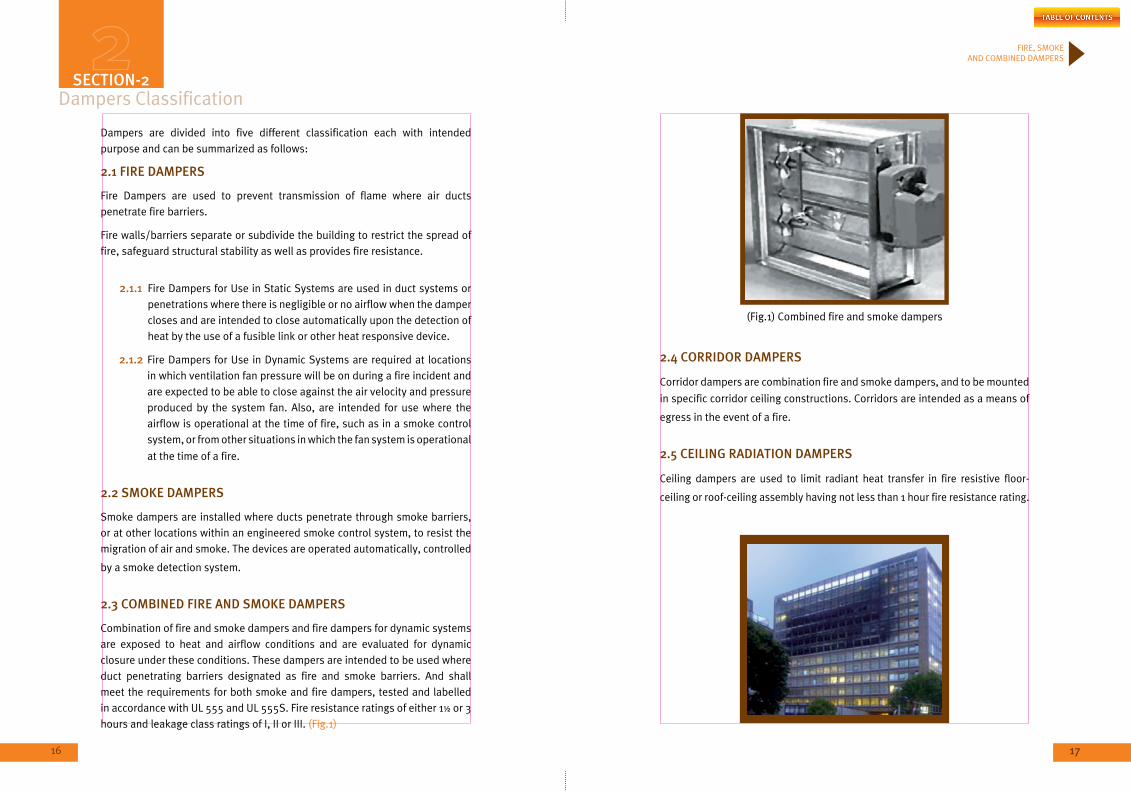
2.3 CombinED FiRE AnD SmoKE DAmPERS
Combination of fire and smoke dampers and fire dampers for dynamic systems are exposed to heat and airflow conditions and are evaluated for dynamic closure under these conditions. These dampers are intended to be used where duct penetrating barriers designated as fire and smoke barriers. And shall meet the requirements for both smoke and fire dampers, tested and labelled in accordance with UL 555 and UL 555S. Fire resistance ratings of either 1½ or 3 hours and leakage class ratings of I, II or III. (Fig.1)
(Fig.1) Combined fire and smoke dampers
2.4 CoRRiDoR DAmPERS
Corridor dampers are combination fire and smoke dampers, and to be mounted
in specific corridor ceiling constructions. Corridors are intended as a means of
egress in the event of a fire.
2.5 CEiLinG RADiATion DAmPERS
Ceiling dampers are used to limit radiant heat transfer in fire resistive floor-
ceiling or roof-ceiling assembly having not less than 1 hour fire resistance rating.
SECTion-2
18 19
S E C T I O N
3
FiRE DAmPERS
21
FIRE, SMOKE AND COMBINED DAMPERS
20
3.1 WHERE To bE USED?
The function of a Fire Damper is to close automatically upon detection of heat in order to protect the integrity of a fire barrier and maintain its fire resistance rating where penetrated by HVAC ductwork or equipment. Failure of these dampers to fully close in the event of a fire may lead to a disastrous loss of life and/or property.
3.2 TYPES oF FiRE DAmPERS
3.2.1 Static Fire Damper:
(a) A device designed to impede the spread of fire through walls, floors and partitions. Its construction includes a galvanized steel frame and a fusible link, a heat sensitive device (usually set at 165°F). When the fusible link opens, it releases the damper components to close. When the damper components are close, the damper will restrict the migration of fire. Fire damper products are listed with hourly ratings.
(b) Dampers are also listed as standard (static) dampers and installed in a system where fan will be shut off in case of fire (no airflow in the system), damper to be rated for Static System.
3.2.2 Dynamic Fire Damper:
A fire damper that is listed and approved for applications is the HVAC system whose blower may continue to run during the alarm. Dynamic fire dampers are rated to close against the moving air measured in feet-per-minute (fpm) velocity. Dampers installed in the system shall be rated for dynamic system where fan will be running in case of fire (airflow in the system).
3.3 FiRE DAmPERS RATinGS
Dampers shall be tested, rated and labelled in accordance with UL 555
Standards (Sixth Edition) as follow:
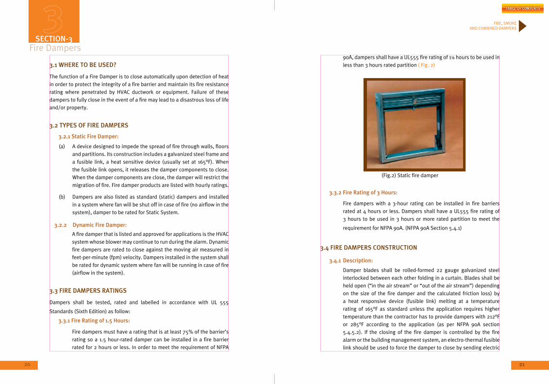
3.3.1 Fire Rating of 1.5 Hours:
Fire dampers must have a rating that is at least 75% of the barrier’s rating so a 1.5 hour-rated damper can be installed in a fire barrier rated for 2 hours or less. In order to meet the requirement of NFPA
90A, dampers shall have a UL555 fire rating of 1½ hours to be used in less than 3 hours rated partition ( Fig. 2)
(Fig.2) Static fire damper
3.3.2 Fire Rating of 3 Hours:
Fire dampers with a 3-hour rating can be installed in fire barriers rated at 4 hours or less. Dampers shall have a UL555 fire rating of 3 hours to be used in 3 hours or more rated partition to meet the
requirement for NFPA 90A. (NFPA 90A Section 5.4.1)
3.4 FiRE DAmPERS ConSTRUCTion
3.4.1 Description:
Damper blades shall be rolled-formed 22 gauge galvanized steel interlocked between each other folding in a curtain. Blades shall be held open (“in the air stream” or “out of the air stream”) depending on the size of the fire damper and the calculated friction loss) by a heat responsive device (fusible link) melting at a temperature rating of 165°F as standard unless the application requires higher temperature than the contractor has to provide dampers with 212°F or 285°F according to the application (as per NFPA 90A section 5.4.5.2). If the closing of the fire damper is controlled by the fire alarm or the building management system, an electro-thermal fusible link should be used to force the damper to close by sending electric
Fire DampersSECTion-3
22 23
FIRE, SMOKE AND COMBINED DAMPERS
signal to the fusible link & melt it before the fire melt the fusible link. Damper frames shall be rolled-formed 22 gauge galvanized steel with reinforced corners.
Fire damper should be equipped with a closure spring engaged into a locking ramp to ensure correct operation regardless of whether the damper is horizontally or vertically mounted. The locking ramp should be provided with Blade Lock which will keep the blade in a closed position under Airflow. Damper with locking ramp flat & without lock should not be approved. These dampers are intended to be used in Static & Dynamic system.
Damper intend to be used in Dynamic System can be curtain type or could be provided as multi-blade type with a 16 gauge galvanized steel construction with 3V type Blade with three longitudinal grooves for reinforcement. Blades shall be linked together with external linkage (out of air stream).
Damper frames shall be 16 gauge galvanized steel formed into a structural hat channel shape with reinforced corners. Bearings shall be sintered bronze, oil impregnated type rotating in extruded holes in the damper frame.
Damper shall be installed in a factory mounted sleeve with a minimum thickness of 1mm to meet the requirement of section 5.4.6.3.1 of NFPA 90A.
Fire Damper should have a UL Classified Labelled with the rating on. Any damper not holding a UL label with Serial number shall not be
installed.
3.4.2 Construction Components and Accessories
3.4.2.1 Frame: The portion of the fire damper that houses the damper blades, fusible link, locking ramps, transitions and springs (if
springs are required).
3.4.2.2 Framed Retaining Angles: Framed retaining angles attach to the sleeve on both sides of the fire rated floor, wall or partition to secure it in place. The framed retaining angle must also cover the openings between the outside of the sleeve and the inside of the hole in the fire rated barrier. Framed retaining angles should not be attached to the fire rated barrier.
3.4.2.3 Access Door: All installed fire dampers must be accessible for inspection and/or testing by the local authorities. If fire dampers are not accessible from a grill or register, an access door in the ductwork is required. Access panel shall not decrease the duct integrity and shall be UL classified.
3.4.2.4 Fusible Link: A temperature sensitive device that holds the damper components in the open position, which in turn, allows air to pass through. When the fusible link opens, it releases the damper components to close, and they will stay closed until a new fusible link is installed. The temperature rating of the
standard fusible link is 165°F. Different temperature ratings are
available.
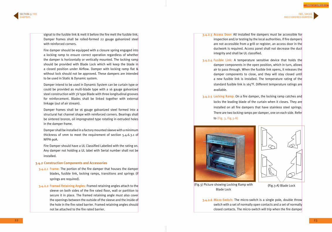
3.4.2.5 Locking Ramp: On a fire damper, the locking ramp catches and
locks the leading blade of the curtain when it closes. They are
installed on all fire dampers that have stainless steel springs.
There are two locking ramps per damper, one on each side. Refer
to (Fig. 3, Fig.3-A)
(Fig.3) Picture showing Locking Ramp with
Blade Lock(Fig.3-A) Blade Lock
3.4.2.6 micro-Switch: The micro-switch is a single pole, double throw switch with a set of normally open contacts and a set of normally closed contacts. The micro-switch will trip when the fire damper
SECTION-3: FIRE DAMPERS
24 25
FIRE, SMOKE AND COMBINED DAMPERS
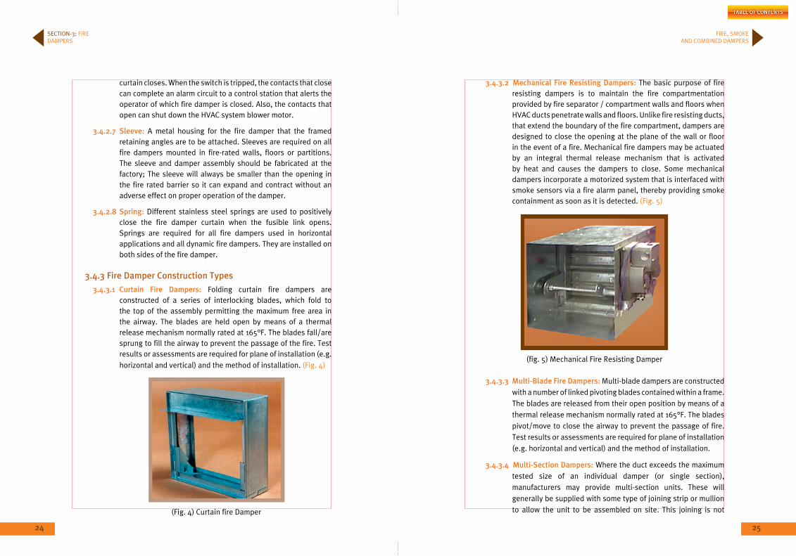
3.4.3.2 mechanical Fire Resisting Dampers: The basic purpose of fire resisting dampers is to maintain the fire compartmentation provided by fire separator / compartment walls and floors when HVAC ducts penetrate walls and floors. Unlike fire resisting ducts, that extend the boundary of the fire compartment, dampers are designed to close the opening at the plane of the wall or floor in the event of a fire. Mechanical fire dampers may be actuated by an integral thermal release mechanism that is activated by heat and causes the dampers to close. Some mechanical dampers incorporate a motorized system that is interfaced with smoke sensors via a fire alarm panel, thereby providing smoke containment as soon as it is detected. (Fig. 5)
(fig. 5) Mechanical Fire Resisting Damper
3.4.3.3 multi-blade Fire Dampers: Multi-blade dampers are constructed with a number of linked pivoting blades contained within a frame. The blades are released from their open position by means of a thermal release mechanism normally rated at 165°F. The blades pivot/move to close the airway to prevent the passage of fire. Test results or assessments are required for plane of installation (e.g. horizontal and vertical) and the method of installation.
3.4.3.4 multi-Section Dampers: Where the duct exceeds the maximum tested size of an individual damper (or single section), manufacturers may provide multi-section units. These will generally be supplied with some type of joining strip or mullion to allow the unit to be assembled on site. This joining is not
curtain closes. When the switch is tripped, the contacts that close can complete an alarm circuit to a control station that alerts the operator of which fire damper is closed. Also, the contacts that open can shut down the HVAC system blower motor.
3.4.2.7 Sleeve: A metal housing for the fire damper that the framed retaining angles are to be attached. Sleeves are required on all fire dampers mounted in fire-rated walls, floors or partitions. The sleeve and damper assembly should be fabricated at the factory; The sleeve will always be smaller than the opening in the fire rated barrier so it can expand and contract without an adverse effect on proper operation of the damper.
3.4.2.8 Spring: Different stainless steel springs are used to positively close the fire damper curtain when the fusible link opens. Springs are required for all fire dampers used in horizontal applications and all dynamic fire dampers. They are installed on both sides of the fire damper.
3.4.3 Fire Damper Construction Types
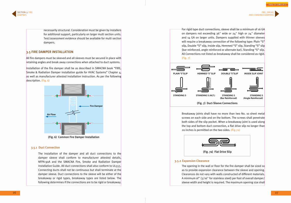
3.4.3.1 Curtain Fire Dampers: Folding curtain fire dampers are constructed of a series of interlocking blades, which fold to the top of the assembly permitting the maximum free area in the airway. The blades are held open by means of a thermal release mechanism normally rated at 165°F. The blades fall/are sprung to fill the airway to prevent the passage of the fire. Test results or assessments are required for plane of installation (e.g. horizontal and vertical) and the method of installation. (Fig. 4)
SECTION-3: FIRE DAMPERS
(Fig. 4) Curtain fire Damper
26 27
FIRE, SMOKE AND COMBINED DAMPERS
necessarily structural. Consideration must be given by installers for additional support, particularly on larger multi section units. Test/assessment evidence should be available for multi section dampers.
3.5 FiRE DAmPER inSTALLATion
All fire dampers must be sleeved and all sleeves must be secured in place with retaining angles and break away connections when attached to duct systems.
Installation of the fire damper shall be as described in SMACNA book “FIRE, Smoke & Radiation Damper installation guide for HVAC Systems” Chapter 4, as well as manufacturer attested installation instruction. As per the following description. (Fig. 6)
(Fig. 6) Common Fire Damper installation
3.5.1 Duct Connection
The installation of the damper and all duct connections to the damper sleeve shall conform to manufacturer attested details, NFPA-90A and the SMACNA Fire, Smoke and Radiation Damper Installation Guide. All duct connections shall also conform to UL555. Connecting ducts shall not be continuous but shall terminate at the damper sleeve. Duct connections to the sleeve will be either of the breakaway or rigid types, breakaway types are listed below. The following determines if the connections are to be rigid or breakaway.
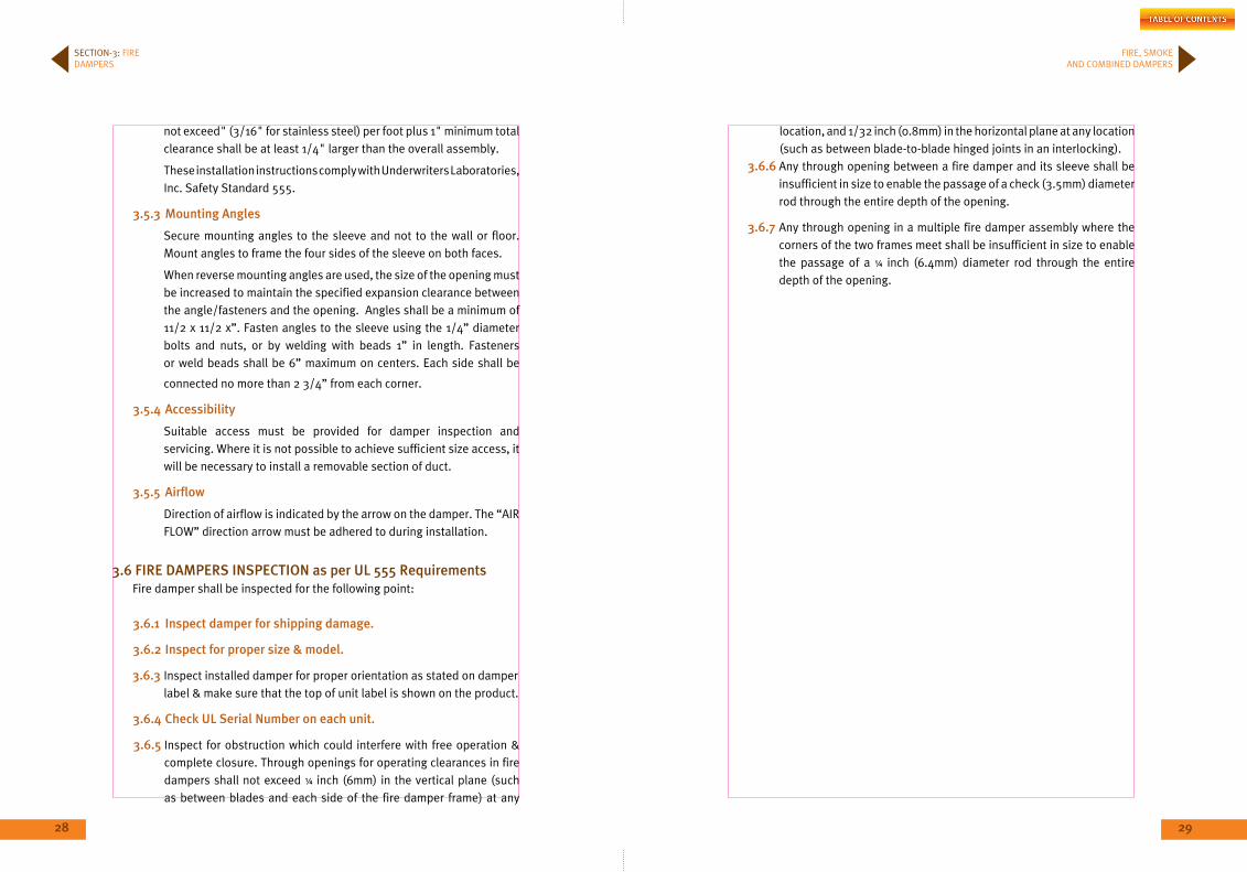
For rigid type duct connections, sleeve shall be a minimum of 16 GA on dampers not exceeding 36" wide or 24" high or 24" diameter and 14 GA on larger units. Dampers supplied with thinner sleeves will require a breakaway connection of the following type: Plain “S” slip, Double “S” slip, Inside slip, Hemmed “S” slip, Standing “S” slip (bar reinforced, angle reinforced or alternate bar), Standing “S” slip. All Connections not listed as breakaway shall be considered as rigid. (Fig. 7)
(Fig. 7) Duct-Sleeve Connections
Breakaway joints shall have no more than two No. 10 sheet metal screws on each side and on the bottom. The screws shall penetrate both sides of the slip pocket. When a breakaway joint is used along the top and bottom duct connection, a flat drive slip no longer than 20 inches is permitted on the two sides. (Fig.7a)
(Fig. 7a) Flat Drive Slip
3.5.2 Expansion Clearance
The opening in the wall or floor for the fire damper shall be sized so as to provide expansion clearance between the sleeve and opening. Clearances do not vary with walls constructed of different materials. A minimum of" (3/16" for stainless steel) per foot of overall damper/sleeve width and height is required. The maximum opening size shall
SECTION-3: FIRE DAMPERS
28 29
FIRE, SMOKE AND COMBINED DAMPERS
not exceed" (3/16" for stainless steel) per foot plus 1" minimum total clearance shall be at least 1/4" larger than the overall assembly.
These installation instructions comply with Underwriters Laboratories, Inc. Safety Standard 555.
3.5.3 mounting Angles
Secure mounting angles to the sleeve and not to the wall or floor. Mount angles to frame the four sides of the sleeve on both faces.
When reverse mounting angles are used, the size of the opening must be increased to maintain the specified expansion clearance between the angle/fasteners and the opening. Angles shall be a minimum of 11/2 x 11/2 x”. Fasten angles to the sleeve using the 1/4” diameter bolts and nuts, or by welding with beads 1” in length. Fasteners or weld beads shall be 6” maximum on centers. Each side shall be
connected no more than 2 3/4” from each corner.
3.5.4 Accessibility
Suitable access must be provided for damper inspection and servicing. Where it is not possible to achieve sufficient size access, it will be necessary to install a removable section of duct.
3.5.5 Airflow
Direction of airflow is indicated by the arrow on the damper. The “AIR FLOW” direction arrow must be adhered to during installation.
3.6 FiRE DAmPERS inSPECTion as per UL 555 RequirementsFire damper shall be inspected for the following point:
3.6.1 inspect damper for shipping damage.
3.6.2 inspect for proper size & model.
3.6.3 Inspect installed damper for proper orientation as stated on damper label & make sure that the top of unit label is shown on the product.
3.6.4 Check UL Serial number on each unit.
3.6.5 Inspect for obstruction which could interfere with free operation & complete closure. Through openings for operating clearances in fire dampers shall not exceed ¼ inch (6mm) in the vertical plane (such as between blades and each side of the fire damper frame) at any
location, and 1/32 inch (0.8mm) in the horizontal plane at any location (such as between blade-to-blade hinged joints in an interlocking).
3.6.6 Any through opening between a fire damper and its sleeve shall be insufficient in size to enable the passage of a check (3.5mm) diameter rod through the entire depth of the opening.
3.6.7 Any through opening in a multiple fire damper assembly where the corners of the two frames meet shall be insufficient in size to enable the passage of a ¼ inch (6.4mm) diameter rod through the entire depth of the opening.
SECTION-3: FIRE DAMPERS

30 31
S E C T I O N
4
SmoKE mAnAGEmEnT SYSTEm
33
FIRE, SMOKE AND COMBINED DAMPERS
32
Smoke Management System
4.1 FoREWoRD
Fire produce smoke which if not controlled or managed in some way, it will spread throughout the building or portions of the building to endanger life and property. Even small fire produce a large volume of smoke. Smoke can spread in buildings through construction cracks, pipe penetrations, and open doors in addition to action of the air distribution system. The principle driving forces of smoke movement are stack effect, buoyancy and expansion of the combustion gases caused by increased temperature, weather (principally wind and temperature) and the air distribution or the HVAC system. The objective of a smoke control system should be to maintain a reasonable environment in the means of escape out, to limit or control smoke spread from the fire area and to aid fire fighters or other emergency responders in their search and rescue efforts.
As previously defined, smoke management systems include all methods that can be used separately or in combination to modify smoke movement. These systems are described in NFPA92A&B. They particularly involve exhaust or venting to manage smoke.
4.2 APPLiCATion AnD DESiGn mAnDAToRY
All Residential buildings above three stories in height shall be protected by a controlled automatic sprinkler system for total or partial coverage as per NFPA 13, and other NFPA relevant sections such as but not limited to section 101. Each apartment is considered as Smoke zone if the number of apartments in the floor exceeds 6 - unless the area of the apartment exceeds 120 m2 or travelling distance to nearest fire exit 38 m for partial coverage & 61 m for Total coverage, otherwise the flat will be considered as smoke and fire zone. Apartment should be protected by a Fire smoke barrier rated for 2hrs and Fire & smoke door rated for 1½ hours & combined fire and smoke damper rated for 1½ hours.
4.3 bASiC SYSTEm TYPES
Systems for controlling smoke movement in buildings can generally be divided into two separate types:
4.3.1 Shaft protection:
Further it is divided into Stairwell Pressurization System & Elevator Shaft System.
4.3.1.1 Shaft Protection –Stairwell Pressuriz: The objective of pressurized stairwell is to provide an acceptable environment within the stairwell in the vent of a building fire. A secondary objective is to provide a clean area for fire fighters and rescue team. The stairwell pressurization system should be designed to meet or exceed the minimum pressure given in NFPA 92A Table 2.2.1 & should not exceed the maximum pressure difference given in NFPA 92A Table 2.2.2.
4.3.1.2 Shaft Protection– Elevator Shaft: Historically, elevator shaft (where the cabin & the rail of the elevator runs) have proved to be a readily available conduit for the movement of smoke throughout the buildings. The reason is that the elevator doors have not been tight fitting and elevator shaft have been provided with openings in their tops. Several methods of correcting this problem have been proposed and investigated. These methods include the following:
(a) Exhaust of fire floor.(b) Pressurization of enclosed elevator lobbies.(c) Construction of smoke tight elevator lobbies.(d) Pressurization of the elevator Shaft.
4.3.2 Floor protection
4.3.2.1 Floor Protection – Smoke Control Zones: The pressurized stairwells are intended to control smoke to the extent that they inhibit smoke infiltration into stairwell. However in a building with a pressurized stairwell only do not prevent the smoke to flow through cracks in floors and partition and through other shafts to threaten life and damage property at a location remotely from the fire. The concept of zoned smoke control is intended to limit this type of smoke movement within a building.
4.3.3 Combination of systems
4.3.3.1 Combination of Systems: On some occasions, more than one
smoke control system will operate simultaneously. For example pressurized stairwells can connect to floor areas that are part
SECTion-4
34 35
FIRE, SMOKE AND COMBINED DAMPERS
SECTION-4: SMOKE MANAGEMENT SYSTEM
of a zoned smoke control system. Often these systems are designed independently to operate under dynamic forces they will encounter. Once the design is completed it is necessary to study the impact of the smoke control systems might have on one to another. For complex systems, it is recommended that a computer network model to be used for the analysis. See Section 5.3.8 from NFPA 92A for more details.
4.4 SmoKE ConTRoL SYSTEmS
Smoke control systems are a subset of smoke management systems mechanical fans to produce airflows and pressure differences across barriers to limit smoke movement as described in NFPA92A. Stair pressurization; zoned smoke control and pressure sandwich systems are examples of smoke control systems.
4.4.1 Smoke Control System Design Considerations
The first step in designing a smoke control system is to establish the system objective and then method of test to determine compliance with the objective. The objective should be based on an analysis of the building occupancy and construction. Among the factors to consider are the following:
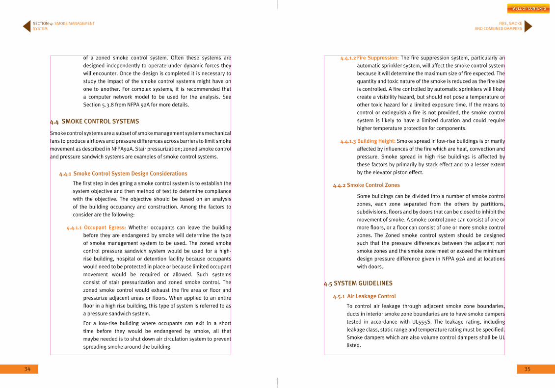
4.4.1.1 occupant Egress: Whether occupants can leave the building before they are endangered by smoke will determine the type of smoke management system to be used. The zoned smoke control pressure sandwich system would be used for a high-rise building, hospital or detention facility because occupants would need to be protected in place or because limited occupant movement would be required or allowed. Such systems consist of stair pressurization and zoned smoke control. The zoned smoke control would exhaust the fire area or floor and pressurize adjacent areas or floors. When applied to an entire floor in a high rise building, this type of system is referred to as a pressure sandwich system.
For a low-rise building where occupants can exit in a short time before they would be endangered by smoke, all that maybe needed is to shut down air circulation system to prevent spreading smoke around the building.
4.4.1.2 Fire Suppression: The fire suppression system, particularly an automatic sprinkler system, will affect the smoke control system because it will determine the maximum size of fire expected. The quantity and toxic nature of the smoke is reduced as the fire size is controlled. A fire controlled by automatic sprinklers will likely create a visibility hazard, but should not pose a temperature or other toxic hazard for a limited exposure time. If the means to control or extinguish a fire is not provided, the smoke control system is likely to have a limited duration and could require higher temperature protection for components.
4.4.1.3 building Height: Smoke spread in low-rise buildings is primarily affected by influences of the fire which are heat, convection and pressure. Smoke spread in high rise buildings is affected by these factors by primarily by stack effect and to a lesser extent by the elevator piston effect.
4.4.2 Smoke Control Zones
Some buildings can be divided into a number of smoke control zones, each zone separated from the others by partitions, subdivisions, floors and by doors that can be closed to inhibit the movement of smoke. A smoke control zone can consist of one or more floors, or a floor can consist of one or more smoke control zones. The Zoned smoke control system should be designed such that the pressure differences between the adjacent non smoke zones and the smoke zone meet or exceed the minimum design pressure difference given in NFPA 92A and at locations with doors.
4.5 SYSTEm GUiDELinES
4.5.1 Air Leakage Control
To control air leakage through adjacent smoke zone boundaries, ducts in interior smoke zone boundaries are to have smoke dampers tested in accordance with UL555S. The leakage rating, including leakage class, static range and temperature rating must be specified. Smoke dampers which are also volume control dampers shall be UL listed.
36 37
FIRE, SMOKE AND COMBINED DAMPERS
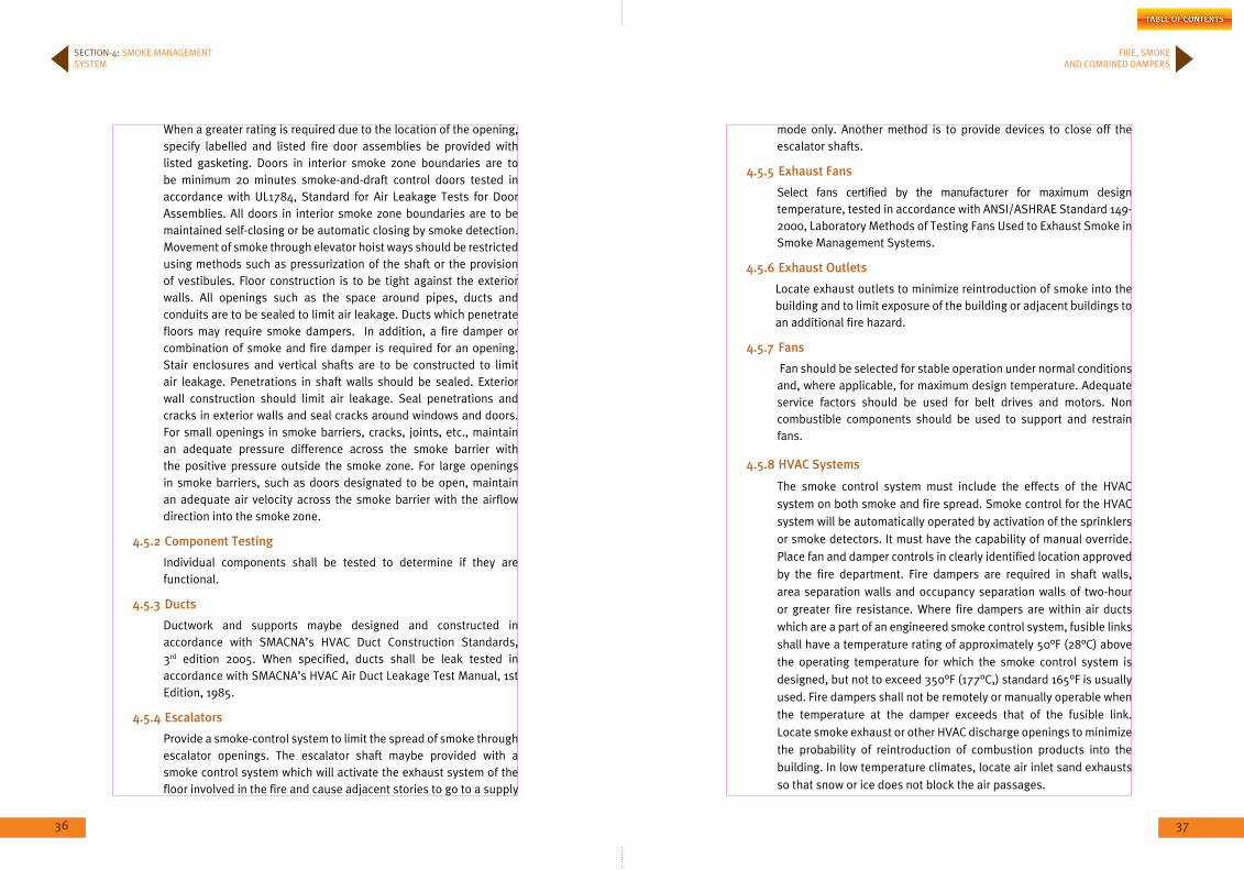
When a greater rating is required due to the location of the opening, specify labelled and listed fire door assemblies be provided with listed gasketing. Doors in interior smoke zone boundaries are to be minimum 20 minutes smoke-and-draft control doors tested in accordance with UL1784, Standard for Air Leakage Tests for Door Assemblies. All doors in interior smoke zone boundaries are to be maintained self-closing or be automatic closing by smoke detection. Movement of smoke through elevator hoist ways should be restricted using methods such as pressurization of the shaft or the provision of vestibules. Floor construction is to be tight against the exterior walls. All openings such as the space around pipes, ducts and conduits are to be sealed to limit air leakage. Ducts which penetrate floors may require smoke dampers. In addition, a fire damper or combination of smoke and fire damper is required for an opening. Stair enclosures and vertical shafts are to be constructed to limit air leakage. Penetrations in shaft walls should be sealed. Exterior wall construction should limit air leakage. Seal penetrations and cracks in exterior walls and seal cracks around windows and doors. For small openings in smoke barriers, cracks, joints, etc., maintain an adequate pressure difference across the smoke barrier with the positive pressure outside the smoke zone. For large openings in smoke barriers, such as doors designated to be open, maintain an adequate air velocity across the smoke barrier with the airflow direction into the smoke zone.
4.5.2 Component Testing
Individual components shall be tested to determine if they are functional.
4.5.3 Ducts
Ductwork and supports maybe designed and constructed in accordance with SMACNA’s HVAC Duct Construction Standards, 3rd edition 2005. When specified, ducts shall be leak tested in accordance with SMACNA’s HVAC Air Duct Leakage Test Manual, 1st Edition, 1985.
4.5.4 Escalators
Provide a smoke-control system to limit the spread of smoke through escalator openings. The escalator shaft maybe provided with a smoke control system which will activate the exhaust system of the floor involved in the fire and cause adjacent stories to go to a supply
mode only. Another method is to provide devices to close off the escalator shafts.
4.5.5 Exhaust Fans
Select fans certified by the manufacturer for maximum design temperature, tested in accordance with ANSI/ASHRAE Standard 149-2000, Laboratory Methods of Testing Fans Used to Exhaust Smoke in Smoke Management Systems.
4.5.6 Exhaust outlets
Locate exhaust outlets to minimize reintroduction of smoke into the building and to limit exposure of the building or adjacent buildings to an additional fire hazard.
4.5.7 Fans
Fan should be selected for stable operation under normal conditions and, where applicable, for maximum design temperature. Adequate service factors should be used for belt drives and motors. Non combustible components should be used to support and restrain fans.
4.5.8 HVAC Systems
The smoke control system must include the effects of the HVAC system on both smoke and fire spread. Smoke control for the HVAC system will be automatically operated by activation of the sprinklers or smoke detectors. It must have the capability of manual override. Place fan and damper controls in clearly identified location approved by the fire department. Fire dampers are required in shaft walls, area separation walls and occupancy separation walls of two-hour or greater fire resistance. Where fire dampers are within air ducts which are a part of an engineered smoke control system, fusible links shall have a temperature rating of approximately 50°F (28°C) above the operating temperature for which the smoke control system is designed, but not to exceed 350°F (177°C,) standard 165°F is usually used. Fire dampers shall not be remotely or manually operable when the temperature at the damper exceeds that of the fusible link. Locate smoke exhaust or other HVAC discharge openings to minimize the probability of reintroduction of combustion products into the building. In low temperature climates, locate air inlet sand exhausts so that snow or ice does not block the air passages.
SECTION-4: SMOKE MANAGEMENT SYSTEM
38 39
FIRE, SMOKE AND COMBINED DAMPERS
4.5.9 number of open Doors
Consider the number of doors that may open simultaneously and how long they may be open. Generally, this will depend on the building occupancy and type of smoke control system.
4.5.10 outside Air inlets
Locate outside air inlets to minimize the potential for reintroduction of smoke or flame into the building.
4.5.11 Power Systems
The smoke control systems should be furnished with two power sources. One is the normal building power system and the other is an independent, automatically controlled power source.
4.5.12 Smoke barriers
Construct and seal smoke barriers to limit leakage areas. Smoke barriers may have selected openings protected by closing devices or adequate airflows which serve to restrict the passage of smoke.
4.5.13 Smoke management by Air Flow Airflow can be used to inhibit smoke migration through openings
such as doorways if the air has sufficient velocity to (1) prevent smoke from leaving the zone (the flow of air is into the smoke zone from adjacent areas) and (2) not be overcome by wind or stack effect. Because the qualities of air required are large, airflow is not usually a practical means of controlling smoke movement.
4.5.14 Smoke management by Dedicated System
Dedicated systems are intended for the purpose of smoke management only. Non-dedicated systems share components with HVAC systems and convert to special operation mode for smoke control. Pressurized stair systems and atrium smoke management systems are examples of dedicated smoke management systems.
4.5.15 Smoke Control by Differential Pressure
A means of controlling smoke movement is by creating an air pressure differential across partitions, floors, and other building components. The principal of pressurization is to establish a higher pressure in adjacent areas than in the smoke zone.
4.5.16 Smoke Detection Systems
Install smoke detectors in the main return or exhaust duct serving each smoke zone and locations required by code. See appendix F for more information of smoke detectors in duct applications.
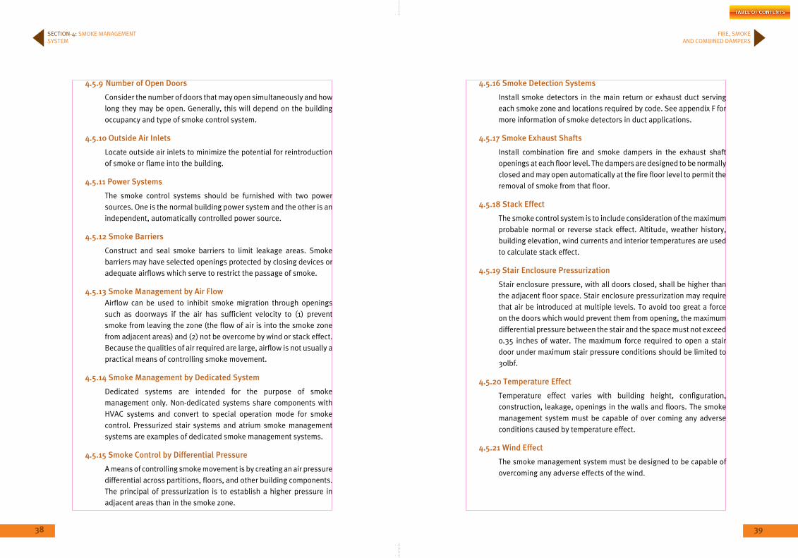
4.5.17 Smoke Exhaust Shafts
Install combination fire and smoke dampers in the exhaust shaft openings at each floor level. The dampers are designed to be normally closed and may open automatically at the fire floor level to permit the removal of smoke from that floor.
4.5.18 Stack Effect
The smoke control system is to include consideration of the maximum probable normal or reverse stack effect. Altitude, weather history, building elevation, wind currents and interior temperatures are used to calculate stack effect.
4.5.19 Stair Enclosure Pressurization
Stair enclosure pressure, with all doors closed, shall be higher than the adjacent floor space. Stair enclosure pressurization may require that air be introduced at multiple levels. To avoid too great a force on the doors which would prevent them from opening, the maximum differential pressure between the stair and the space must not exceed 0.35 inches of water. The maximum force required to open a stair door under maximum stair pressure conditions should be limited to 30lbf.
4.5.20 Temperature Effect
Temperature effect varies with building height, configuration, construction, leakage, openings in the walls and floors. The smoke management system must be capable of over coming any adverse conditions caused by temperature effect.
4.5.21 Wind Effect
The smoke management system must be designed to be capable of overcoming any adverse effects of the wind.
SECTION-4: SMOKE MANAGEMENT SYSTEM
40 41
S E C T I O N
5
SmoKE DAmPERS
43
FIRE, SMOKE AND COMBINED DAMPERS
42
5.1 inTEnDED PURPoSE
For applications where required a leakage rated, smoke damper applied as part of a static smoke control or dynamic smoke management system. Smoke dampers are intended:
(1) To restrict the spread of smoke in HVAC systems that are designed to be automatically closed down in the event of a fire.
(2) To control the movement of smoke within a building when the HVAC system is operational in engineered smoke control systems. Dampers shall meet the requirements of NFPA 90A & NFPA 92A
5.2 DAmPER AiRFLoW RATinG
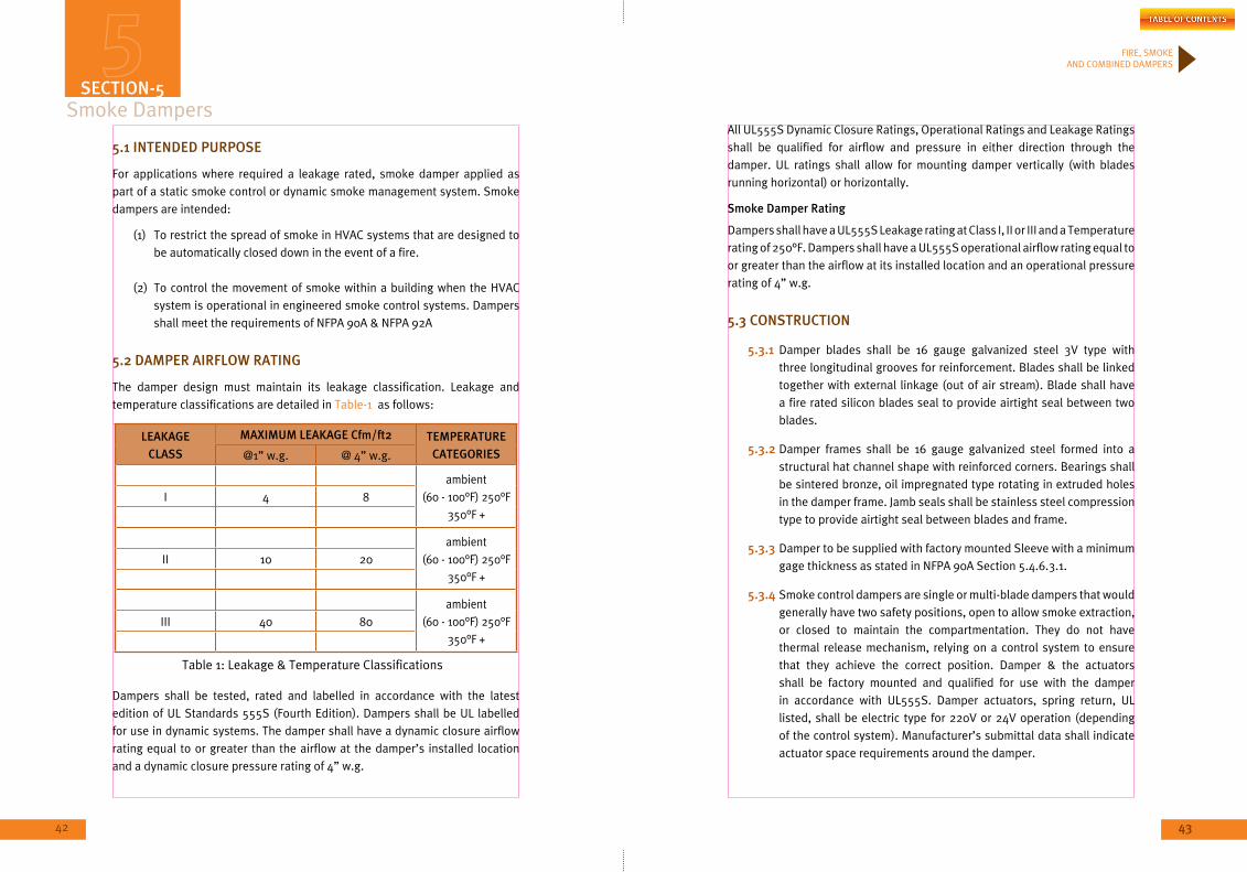
The damper design must maintain its leakage classification. Leakage and temperature classifications are detailed in Table-1 as follows:
LEAKAGE CLASS
mAXimUm LEAKAGE Cfm/ft2 TEmPERATURE CATEGoRiES@1” w.g. @ 4” w.g.
ambient (60 - 100°F) 250°F
350°F +I 4 8
ambient (60 - 100°F) 250°F
350°F +II 10 20
ambient (60 - 100°F) 250°F
350°F +III 40 80
Dampers shall be tested, rated and labelled in accordance with the latest edition of UL Standards 555S (Fourth Edition). Dampers shall be UL labelled for use in dynamic systems. The damper shall have a dynamic closure airflow rating equal to or greater than the airflow at the damper’s installed location and a dynamic closure pressure rating of 4” w.g.
Smoke DampersAll UL555S Dynamic Closure Ratings, Operational Ratings and Leakage Ratings shall be qualified for airflow and pressure in either direction through the damper. UL ratings shall allow for mounting damper vertically (with blades running horizontal) or horizontally.
Smoke Damper Rating
Dampers shall have a UL555S Leakage rating at Class I, II or III and a Temperature rating of 250°F. Dampers shall have a UL555S operational airflow rating equal to or greater than the airflow at its installed location and an operational pressure rating of 4” w.g.
5.3 ConSTRUCTion
5.3.1 Damper blades shall be 16 gauge galvanized steel 3V type with three longitudinal grooves for reinforcement. Blades shall be linked together with external linkage (out of air stream). Blade shall have a fire rated silicon blades seal to provide airtight seal between two blades.
5.3.2 Damper frames shall be 16 gauge galvanized steel formed into a structural hat channel shape with reinforced corners. Bearings shall be sintered bronze, oil impregnated type rotating in extruded holes in the damper frame. Jamb seals shall be stainless steel compression type to provide airtight seal between blades and frame.
5.3.3 Damper to be supplied with factory mounted Sleeve with a minimum gage thickness as stated in NFPA 90A Section 5.4.6.3.1.
5.3.4 Smoke control dampers are single or multi-blade dampers that would generally have two safety positions, open to allow smoke extraction, or closed to maintain the compartmentation. They do not have thermal release mechanism, relying on a control system to ensure that they achieve the correct position. Damper & the actuators shall be factory mounted and qualified for use with the damper in accordance with UL555S. Damper actuators, spring return, UL listed, shall be electric type for 220V or 24V operation (depending of the control system). Manufacturer’s submittal data shall indicate actuator space requirements around the damper.
SECTion-5
Table 1: Leakage & Temperature Classifications
44 45
FIRE, SMOKE AND COMBINED DAMPERS
SECTION-5: SMOKE DAMPERS
5.4. ComPonEnTS AnD ACCESSoRiES
5.4.1 Actuators
UL classifies the actuators for use with smoke dampers and their performance either at ambient or at elevated temperature. The performance of a damper/actuator at an elevated temperature is usually limited by the actuator’s capability.
Smoke dampers and combination fire and smoke dampers are equipped with actuators (electric motors or pneumatic) to remotely control the dampers. These actuators shall be factory mounted to comply with UL 555S requirement. The airflow and pressure ratings marked on the dampers are dependent upon the particular combination of damper type, actuator type and linkages between the damper blades and actuator.
5.4.2 Detectors
Smoke dampers may be required to be closed by smoke detectors. As per Section 8.3.5 of the Life Safety Code, NFPA101 requires dampers to be activated by a detector.
Duct type smoke detectors have a minimum and maximum airflow rating. The ratings must be compatible with the ratings of the smoke damper. Smoke dampers have a minimum airflow rating and the maximum is marked on the damper. Duct type smoke detectors typically have a minimum airflow rating of 300-500 fpm. However, there are duct type smoke detector models available that are rated for use at zero airflow. For HVAC systems that are shut down in the event of a fire, smoke dampers equipped with duct type detectors, with a greater than zero minimum airflow rating, may also need to be controlled with a device that will shut the damper in the event that the damper is in the open position and the fans are shut down.
Each smoke damper should be equipped with approved bus system to communicate with the monitoring systems.
5.5 inSTALLATion
Installation of the Fire Smoke damper shall be as describe in SMACNA book “FIRE, Smoke & Radiation Damper installation guide for HVAC Systems” Chapter 4, also as per the attested installation instructions of the manufacturer.
Damper to be supplied with factory mounted sleeves.
Wiring: The installation of electrical wiring and equipment associated with the operation and control of air-conditioning and ventilating systems shall be in accordance with NFPA70, National Electrical Code.
Smoke dampers shall be installed at or adjacent to the point where air ducts pass through required smoke barriers, but in no case shall a smoke damper be installed more than 0.6m (2 ft) from the barrier, or after the first air duct inlet or outlet, which ever is closer to the smoke barrier, unless otherwise permitted by NFPA 90A section 5.3.5.1.1 through 5.3.5.1.5.
5.6 TESTinG as per UL555S
In addition to leakage testing, each damper must pass the following for operational reliability:
(a) 20,000 cycle operational test.
(b) Degradation test Opening and closing against system pressures of 4” w.g. minimum and air velocities of 2,000 fpm minimum up to 4” w.g. at rated temperature.
(c) Leakage tests (250°F standard, 350°F + optional).

46 47
S E C T I O N
6
CombinEDFiRE AnD SmoKE
DAmPERS
49
FIRE, SMOKE AND COMBINED DAMPERS
48
Combined Fire and Smoke DampersSECTion-6
6.1 inTEnDED PURPoSE
Combined Fire and Smoke dampers shall be provided wherever ductwork passes through a fire and smoke barrier or protected shaft in walls, floor and ceilings & shall be used in all fire smoke management application & all areas that use automatic gas extinguishers (CO2, FM200…). Dampers shall meet the requirements of NFPA 90A & NFPA 92A and the requirements of both fire dampers and smoke dampers as per UL 555 and UL 555S.
6.2 ConSTRUCTion
Damper blades shall be 16 gauge galvanized steel 3V type with three longitudinal grooves for reinforcement. Blades shall be linked together with external linkage (out of air stream). Blade shall have a fire rated silicon blades seal to provide airtight seal between two blades.
Damper frames shall be 16 galvanized steel formed into a structural hat channel shape with reinforced corners. Bearings shall be sintered bronze, oil impregnated type rotating in extruded holes in the damper frame. Jamb seals shall be stainless steel compression type to provide airtight seal between blades and frame.
Where combination fire and smoke dampers are located within air ducts that are part of an engineered smoke-control system, fusible links or reset able heat responsive devices shall have a temperature rating approximately 28°C (50°F) above the maximum smoke-control system designed operating temperature as per NPFA 90A section 5.4.5.2.2.1. The standard temperature to be used shall be 165°F.
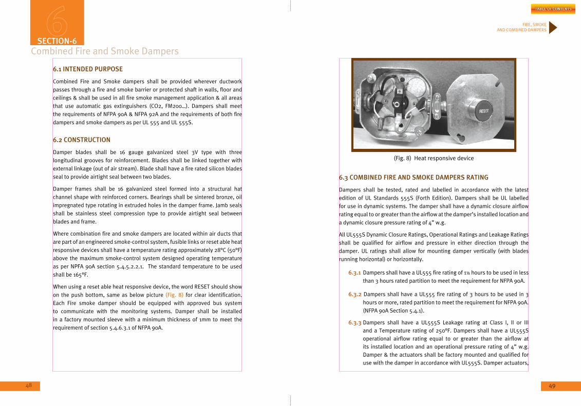
When using a reset able heat responsive device, the word RESET should show on the push bottom, same as below picture (Fig. 8) for clear identification. Each Fire smoke damper should be equipped with approved bus system to communicate with the monitoring systems. Damper shall be installed in a factory mounted sleeve with a minimum thickness of 1mm to meet the requirement of section 5.4.6.3.1 of NFPA 90A.
(Fig. 8) Heat responsive device
6.3 CombinED FiRE AnD SmoKE DAmPERS RATinG
Dampers shall be tested, rated and labelled in accordance with the latest edition of UL Standards 555S (Forth Edition). Dampers shall be UL labelled for use in dynamic systems. The damper shall have a dynamic closure airflow rating equal to or greater than the airflow at the damper’s installed location and a dynamic closure pressure rating of 4” w.g.
All UL555S Dynamic Closure Ratings, Operational Ratings and Leakage Ratings shall be qualified for airflow and pressure in either direction through the damper. UL ratings shall allow for mounting damper vertically (with blades running horizontal) or horizontally.
6.3.1 Dampers shall have a UL555 fire rating of 1½ hours to be used in less than 3 hours rated partition to meet the requirement for NFPA 90A.
6.3.2 Dampers shall have a UL555 fire rating of 3 hours to be used in 3 hours or more, rated partition to meet the requirement for NFPA 90A. (NFPA 90A Section 5.4.1).
6.3.3 Dampers shall have a UL555S Leakage rating at Class I, II or III and a Temperature rating of 250°F. Dampers shall have a UL555S operational airflow rating equal to or greater than the airflow at its installed location and an operational pressure rating of 4” w.g. Damper & the actuators shall be factory mounted and qualified for use with the damper in accordance with UL555S. Damper actuators,

50 51
FIRE, SMOKE AND COMBINED DAMPERS
spring return, UL listed, shall be electric type for 220V or 24V operation (depending of the control system). Manufacturer’s submittal data shall indicate actuator space requirements around the damper.
6.4 inSTALLATion
Installation of the Fire Smoke damper shall be as describe in SMACNA book “FIRE, Smoke & Radiation Damper installation guide for HVAC Systems” Chapter 4, also as per the attested installation instructions of the manufacturer.
Damper to be supplied with factory mounted sleeves.
Wiring: The installation of electrical wiring and equipment associated with the operation and control of air-conditioning and ventilating systems shall be in accordance with NFPA70, National Electrical Code.
Smoke dampers shall be installed at or adjacent to the point where air ducts pass through required smoke barriers, but in no case shall a smoke damper be installed more than 0.6m (2 ft) from the barrier, or after the first air duct inlet or outlet, which ever is closer to the smoke barrier, unless otherwise permitted by NFPA 90A section 5.3.5.1.1 through 5.3.5.1.5.
6.5 inSPECTion as per UL555 REQUiREmEnTS
Inspect the fire damper, for the following point:
6.5.1 Inspect damper for shipping damage.
6.5.2 Inspect for proper size & model.
6.5.3 Inspect installed damper for proper orientation as stated on damper label & make sure that the top of unit label is shown on the product.
6.5.4 Check UL Serial Number on each unit.
6.5.5 Inspect for obstruction which could interfere with free operation & complete closure.
6.5.6 Through openings for operating clearances in fire dampers shall not exceed ¼ inch (6mm) in the vertical plane (such as between blades and each side of the fire damper frame) at any location, and 1/32 inch (0.8mm) in the horizontal plane at any location (such as between blade-to-blade hinged joints in an interlocking).
6.5.7 Any through opening between a fire damper and its sleeve shall be insufficient in size to enable the passage of a 1/8 inch (3.5mm) diameter rod through the entire depth of the opening.
6.5.8 Any through opening in a multiple fire damper assembly where the corners of the two frames meet shall be insufficient in size to enable the passage of a ¼ inch (6.4mm) diameter rod through the entire depth of the opening.
6.5.9 Actuator power voltage.
6.5.10 Actuator position (left/right).
6.5.11 Actuator and damper normal status (normal close, normal open).
SECTION-6: COMBINED FIRE AND SMOKE DAMPERS
52 53
S E C T I O N
7
Common REQUiREmEnTS To ALL DAmPERS TYPES

55
FIRE, SMOKE AND COMBINED DAMPERS
54
Common Requirements to All Dampers Types
7.1 ConSTRUCTion AnD inSTALLATion
7.1.1 SPECiFiC REQUiREmEnTS:
7.1.1.1 Any method of installation specified or used shall always be furnace tested and UL classified.
7.1.1.2 Whilst manufacturers recommended details may work under laboratory conditions, they may not always be suited to the prevailing site conditions with regard to space and access. The responsibility of a successful installation cannot just be passed down to the ‘last man in’, but rather with all parties involved.
7.1.1.3 Whilst it is very important to ensure that only tested dampers and installation details are used on site, it is imperative that damper manufacturers tested installation methods that are applicable to site conditions. Close liaison between damper manufacturers and installers is essential.
7.1.1.4 To ensure that all coordination drawings and shop drawings has been prepared and approved by project consultant, prior to start installing MEP services. Special attention should be paid for duct sizes and locations to be accurately set out.
7.1.1.5 Even in the presence of detail design drawings, it is imperative that coordination drawings and approved shop drawings be used for the successful installation of dampers especially for openings, duct sizes and location.
7.1.1.6 Ensure that the type of fire-stopping system required to complete damper installation is incompliance with international standards and manufacturer recommendations.
7.1.1.7 Ensure that all installations have been fully incompliance with attested installation method statement.
7.1.1.8 Ensure that Dampers testing, classification and selection are relevant and applicable to the particular case on site. This is a basic requirement of all fire protection systems. This failing results in endemic incorrect application and installation. It should never be overlooked that tested installation methods
are carried out under ‘laboratory conditions’ but should only be selected / indicated by the system designer if detailed consideration is given to the site conditions and installation sequence.
7.1.1.9 Ensure that damper frame selection is accurately correct because the incorrect damper frame selection is critical to installation's success.
7.1.1.10 Ensure that high level of consideration is given to the fact that dampers sealed in floors may have to conform to load bearing requirements to allow access for inspection and maintenance through the building.
7.1.1.11 Freedom from obstructions and spatial requirements, there is very often a lack of space in which to fit services. The system designer should allow sufficient space for the selected method of installation to be used.
7.1.1.12 Ensuring that an area on the appropriate side of the fire barrier is free of services or other obstructions that would prevent access to the damper/access panel(s) which will be fitted into the connecting ductwork or damper plenum adjacent to the damper unit.
7.1.1.13 Ductwork takes up a great deal of room which can affect overall costs. This leads to difficulties caused by lack of access in construction and long term routine maintenance.
7.1.1.14 UL 555, UL 555S, are the test standards for fire dampers and smoke dampers respectively. combination fire and smoke damper must meet the requirements for both UL test standards, based on these tests, dampers are given a fire rating and leakage rating.
7.1.1.15 Manufacturers are testing these dampers at UL with specific mounting and installation requirements. If damper is then installed in a project in accordance with those requirement and instruction, it can be designated as approved installation.
7.1.1.16 Any deviations during installation from the approved instructions, damper installation could render the installation rejected.
SECTion-7
56 57
FIRE, SMOKE AND COMBINED DAMPERS
SECTION-7: COMMON REQUIREMENTS TO ALL DAMPERS TYPES
7.1.1.17 All dampers shall be mounted in sleeves, sleeve/damper assembly is mounted in the fire/smoke barrier and the assembly is held in position by retaining angle on both sides of the fire separation. The retaining angles are fastened to the sleeve but shall not be fastened to the wall, floor etc.
7.1.1.18 Space between the sleeve and wall or floor is left to allow for thermal expansion in the event of heated airflow through the damper/sleeve assembly.
7.1.1.19 Introduction of any material including mineral wool, ceramic fibres or sealants of any kind into the required expansion space between the damper sleeve and fire partition is violation of manufacturer’s conditions of test and listing and could void the UL listing of the damper and could render the damper inoperable.
7.1.2 SPECiAL FACToRS:
The following factors shall be taken into consideration when the installation sequence has been determined. At the time of installation, check that:
7.1.2.1 There is sufficient space on all four sides of the damper for the appropriate contractor to apply/fit masking clamps, mechanical fixings, butts, penetration seals, mastic beads, etc... It must be remembered that as ductwork and barrier installation progresses, inaccessible ‘voids’ / cavities can be formed where the ductwork is either tight against a wall or tight up to the underside of a structural soffit.
7.1.2.2 Would the presence of building services being installed at a lower level than the damper prevent the damper/duct items being safely lifted into their installation position?
7.1.2.3 Would the presence of primary ceiling grids at a lower level than the damper prevent the damper and/or the ductwork being safely lifted into their installation position?
7.1.3 FiRE bARRiERS
Ensure that the installer responsible for the construction of the fire barriers is given instructions by the designer/contractor on
the requirements to seal the initial open penetrations, including all dimensional information. They should also be instructed on any finishing-off activities and the sequence in which they should be carried out relative to both the installation of the damper assembly and the connecting ductwork.
Openings formed for ductwork often have no consideration for the damper unit and its frame. In solid walls this leaves openings too small to fit the damper or too large to seal in a cost effective way. In wall this means that openings must be reformed which may render the construction of the opening, required to the fire tested standard recommended by the manufacturer, impossible without significant additional work and cost.
7.1.4 SEALS
Indicate, where necessary, the type of seals that is to be used to make good any clearance space within the fire barrier and around the damper to ensure that the integrity and insulation of the fire barrier is maintained.
All parties involved in both the installation sequence and the installation activities should recognize that the final installation will be checked for validity by an authorized representative of pertinent authority. Failure by any party to correctly interpret installation procedures may result in extremely expensive corrective action, especially if the prevailing conditions involve the temporary removal of ‘obstacles’ / services that interfere with the successful rectification of a problem.
7.1.5 mAin inSTALLATion CRiTERiA
Regardless of the type of fire barrier in which the damper is to be mounted, there are only two main design criteria to be met and they are:
1 That the damper should be fixed either within or directly adjacent to the fire barrier and be supported independently of the connecting ductwork, i.e. if the ductwork were to be removed from both sides of the damper it would continue to be an integral member of the barrier it protects.
58 59
FIRE, SMOKE AND COMBINED DAMPERS
2 That the damper is installed in accordance with the manufacturers recommended tested method.
7.1.6 SToRAGE AnD HAnDLinG
7.1.6.1 Storage area temperature level shall be checked: temperature of storage area shall not reach 68°C and should never be exposed to sun to avoid fusible link melt or bow.
7.1.6.2 Storage area shall be clean and away from any dust, sands and oils, whilst these elements will affect the blades mechanism.
7.2 TESTinG AnD CommiSSioninG 7.2.1 inTRoDUCTion
The following requirements are in compliance with the 2002 Edition of NFPA-90A Standard for the Installation of Air-Conditioning and Ventilating Systems, as well as the 2007 Edition of NFPA-105 Standard for the Installation of Smoke Door Assemblies and Other Opening Protective, NFPA92B and the 2007 Edition of NFPA-80 Standard for Fire Doors and Other Opening Protective.
The following is a list of the code sections used in the preparation of this document: NFPA-80 19.3-19.5.5, NFPA-105 6.4-6.6.6, NFPA-90A 5.4.7, 5.4.3.1, 5.4.3.2 and NFPA-92B 8.4.5-8.4.5.4, as described here below:
"NFPA 19.4 Mandates the Testing of Dampers
19.4.4 If the dampers are equipped with a fusible link, the link shall be removed for testing to ensure full closure and lock-in-place if so equipped.
19.4.5 The operational test of the damper shall verify that there is no damper interference due to rusted, bent, misaligned for damaged frame, or blades or defective hinges or other moving parts.
19.4.6 The damper frame shall not be penetrated by any foreign objects that would affect fire damper operations.
19.4.7 The damper shall not be blocked in closure in any way.
19.4.8 The fusible link shall be reinstalled after testing is complete.
19.4.8.1 If the link is damaged or painted, it shall be replaced with a link of the same size, temperature, and load
rating.
19.4.9 All inspections and testing shall be documented indicating the location of the fire or combination fire/smoke damper, date of inspection, name of inspector, and deficiencies discovered.
19.4.10 ALL documentation shall be maintained and made available for review by the AHJ Trakhees.
7.2.2 FiRE DAmPERS
7.2.2.1 After installation is completed an operational test needs to be conducted.
7.2.2.2 The damper needs to be fully closed (automatically) from the open position fusible link needs to be removed for this test. Note that the fusible link needs to be re-installed after the completion of the test.
7.2.2.3 The operational test needs to verify that the damper operation is not obstructed.
7.2.2.4 The operational test needs to verify that there is full and unobstructed access to the damper and all components.
7.2.2.5 It needs to be verified that all indicating devices work and report to the intended location.
7.2.2.6 The fusible link’s operating temperature needs to be in accordance with NFPA-90A.
7.2.2.7 Following the completion of the test, a visual inspection needs to be made of the assembly to ensure no obstructions have been introduced.
7.2.2.8 All inspections and testing need to be documented indicating the location of the damper, date of inspection, name of the inspector and deficiencies discovered. The documentation needs to have a space to indicate when and how the deficiencies were corrected.
SECTION-7: COMMON REQUIREMENTS TO ALL DAMPERS TYPES
60 61
FIRE, SMOKE AND COMBINED DAMPERS
7.2.2.9 Proper evidence of inspection shall be provided such as checklist, photos, etc.
7.2.3 SmoKE AnD CombinATion oF FiRE AnD SmoKE DAmPERS
7.2.3.1 After installation is completed an operational test needs to be conducted after the buildings HVAC system has been tested, commissioned and balanced.
7.2.3.2 The test must determine that the system functions as intended.
7.2.3.3 The test must be conducted under normal HVAC airflow conditions as well as dynamic flow conditions.
7.2.3.4 The test needs to verify that the damper operation is not obstructed.
7.2.3.5 The test needs to verify that there is full and unobstructed access to the damper and components.
7.2.3.6 It needs to be verified that all indicating devices work and report to the intended location.
7.2.3.7 Following the completion of the test, a visual inspection needs to be made of the assembly to ensure no obstructions have been introduced.
7.2.3.8 All inspections and testing need to be documented indicating the location of the damper, date of inspection, name of the inspector and deficiencies discovered. The documentation needs to have a space to indicate when and how the deficiencies were corrected.
7.2.3.9 Proper evidence of inspection shall be provided such as checklist, photos, etc.
7.3 PERioDiC TESTinG AnD inSPECTion
7.3.1 inTRoDUCTion
The following requirements are in compliance with the 2002 Edition of NFPA-90A Standard for the Installation of Air-Conditioning and Ventilating Systems, as well as the 2007 Edition of NFPA-105 Standard
for the Installation of Smoke Door Assemblies and Other Opening Protective, NFPA92B and the 2007 Edition of NFPA-80 Standard for Fire Doors and Other Opening Protective. The following is a list of the code sections used in the preparation of this document: NFPA-80 19.3-19.5.5, NFPA-105 6.4-6.6.6, NFPA-90A 5.4.7, 5.4.3.1, 5.4.3.2 and NFPA-92B 8.4.5-8.4.5.4. as descried here below:
NFPA 90A (Periodic Inspection and Testing)
(a) If the damper has a fusible link (fire damper or combination), the link needs to be removed for testing to ensure full closure.
(b) The operation test of the damper needs to verify that there is no damper interference due to rusted, bent, misaligned or damaged frame or blades, or defective hinges or parts.
(c) The damper frame must not be penetrated by any foreign objects that would affect fire damper operations (e.g. screws in tracks).
(d) The damper must not be blocked from closure in any way.
(e) The fusible link (if applicable) needs to be reinstalled after the completion of the testing.
(f) If the fusible link (if applicable) is damaged or painted, it should be replaced with a link of the same size, temperature and load rating.
(g) All Inspections and testing need to be documented indicating the location of the damper, date of inspection, name of inspector and deficiencies discovered.
(h) 19.4.1 States that each damper shall be inspected 1 year after installation.
(i) 19.4.1.1 States that testing frequency shall then be every 4 years thereafter except in hospitals.
7.3.2 PERioDiC inSPECTion AnD TESTinG
(Fire Dampers, Smoke Dampers and Combinations F/S Dampers, as applicable)
7.3.2.1 Each damper needs to be tested and inspected 1 year after installation. Tests and Inspections then need to be completed
SECTION-7: COMMON REQUIREMENTS TO ALL DAMPERS TYPES
62 63
FIRE, SMOKE AND COMBINED DAMPERS
in all buildings every 4 years, except in hospitals, where the frequency is every 6 years.
7.3.2.2 All tests need to be completed safely by personnel wearing protective equipment.
7.3.2.3 Unobstructed access to the damper needs to be verified and corrected as required.
7.3.2.4 The damper needs to be actuated and cycled as a part of the associated smoke detector testing in accordance with NFPA-72 (as applicable).
7.3.2.5 If the damper has a fusible link, the link needs to be removed for testing to ensure full closure and lock-in-place if so equipped.
7.3.2.6 The operation test of the damper needs to verify that there is no damper interference due to rusted, bent, misaligned or damaged frame or blades, or defective hinges or parts.
7.3.2.7 The damper frame must not be penetrated by any foreign objects that would affect fire damper operations.
7.3.2.8 The damper must not be blocked from closure in any way.
7.3.2.9 The fusible link (if applicable) needs to be reinstalled after the completion of testing.
7.3.2.10 If the fusible link (if applicable) is damaged or painted, it should be replaced with a link of the same size, temperature and load rating.
7.3.2.11 All inspections and testing need to be documented indicating the location of the damper, date of inspection, name of inspector and deficiencies discovered.
7.3.2.12 The documentation needs to have space to indicate when and how the deficiencies were corrected.
7.3.2.13 All documentation needs to be maintained and made available for review by the AHJ.
7.3.2.14 Proper evidence of inspection shall be provided such as checklist, photos, etc.
7.3.3 ADDiTionAL TESTinG REQUiREmEnTS FoR ATRiA AnD LARGE
SPACES
7.3.3.1 Smoke dampers need to be tested at least semi-annually by persons who are knowledgeable in the operation, testing and maintenance of the systems.
7.3.3.2 The results of the tests need to be documented and made available for inspection.
7.3.3.3 Smoke management systems need to be operated for each sequence in the current design criteria.
7.3.3.4 The tests need to be conducted under standby power if necessary.
7.3.3.5 Proper evidence of inspection shall be provided such as checklist, photos, etc.
7.4 mAinTEnAnCE
MAINTENANCE (Fire Dampers, Smoke Dampers and Combination F/S Dampers)
7.4.1 REFEREnCES
NFPA 90A
7.4.2 mAinTEnAnCE AnD PRoCEDURES
7.4.2.1 Reports of changes in airflow or noise from the duct system need
to be investigated to verify that they are not related to damper operation.
7.4.2.2 All exposed moving parts of the damper need to be dry lubricated as required by the manufacturer.
7.4.2.3 If a damper is inoperable, repairs need to begin without delay.
7.4.2.4 Following any repairs, the damper needs to be tested for operation in accordance with the requirements for Periodic Inspection and Testing.
7.4.2.5 All maintenance needs to be documented.
SECTION-7: COMMON REQUIREMENTS TO ALL DAMPERS TYPES

64
7.4.2.6 The following maintenance needs to be performed at least every 4 years:
1 Fusible links (where applicable) need to be removed.
2 All dampers need to be operated to verify that they close fully.
3 The latch, if provided, needs to be checked.
4 Moving parts need to be lubricated as necessary.
5 Fusible links and other system component need to be fully and correctly reassembled and tested.
7.4.2.7 Proper evidence of inspection shall be provided such as checklist, photos, etc.
SECTION-7: COMMON REQUIREMENTS TO ALL DAMPERS TYPES
A p p e n d i x
A
SELECTED DETAiLS FRom RELEVAnT STAnDARDS FoR
QUiCK REFEREnCE
65
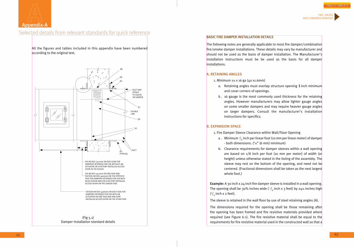
67
FIRE, SMOKE AND COMBINED DAMPERS
66
bASiC FiRE DAmPER inSTALLATion DETAiLS
The following notes are generally applicable to most fire damper/combination fire/smoke damper installations. These details may vary by manufacturer and should not be used as the basis of damper installation. The Manufacturer's installation instructions must be be used as the basis for all damper installations.
A. RETAininG AnGLES
1. Minimum 1½ x 16 ga (40 x1.6mm)
a. Retaining angles must overlap structure opening 1 inch minimum and cover corners of openings.
b . 16 gauge is the most commonly used thickness for the retaining angles. However manufacturers may allow lighter gauge angles on some smaller dampers and may require heavier gauge angles on larger dampers. Consult the manufacturer’s installation instructions for specifics.
b. EXPAnSion SPACE
1. Fire Damper Sleeve Clearance within Wall/Floor Opening
a . Minimum 1/8 inch per linear foot (10 mm per linear meter) of damper
- both dimensions. (‘¼” (6 mm) minimum)
b. Clearance requirements for damper sleeves within a wall opening are based on 1/8 inch per foot (10 mm per meter) of width (or height) unless otherwise stated in the listing of the assembly. The sleeve may rest on the bottom of the opening, and need not be centered. (Fractional dimensions shall be taken as the next largest whole foot.)
Example: A 30 inch x 24 inch fire damper sleeve is installed in a wall opening. The opening shall be 30% inches wide ( 1/
8 inch x 3 feet) by 24¼ inches high
(1/8 inch x 2 feet).
The sleeve is retained in the wall floor by use of steel retaining angles (A).
The dimensions required for the opening shall be those remaining after the opening has been framed and fire resistive materials provided where required (see Figure 6-1). The fire resistive material shall be equal to the requirements for fire resistive material used in the constructed wall so that a
Selected details from relevant standards for quick referenceAppendix-A
(B)
(A)
(E)
DUCT MAY ATTACHTO SLEEVEOR DAMPER
(C)
FUSIBLELINK
(D)
(F)
DUCT(G)(TYPICAL)
SIX INCHES (152mm) ON EACH SIDE FORDAMPERS INTENDED FOR USE WITHOUT ANACTUATOR OR A FACTORY INSTALLED ACCESSDOOR IN THE SLEEVE.
SIX INCHES (152mm) ON ONE SIDE AND SIXTEEN INCHES (406mm) ON THE OPPOSITESIDE FOR DAMPERS INTENDED FOR USE WITHAN ACTUATOR AND/OR A FACTORY INSTALLEDACCESS DOOR ON THE LONGER SIDE.
SIXTEEN INCHES (406mm) ON EACH SIDE FORDAMPERS INTENDED FOR USE WITH AN ACTUATOR ON ONE SIDE AND AFACTORY INSTALLED ACCESS DOOR ON THE OTHER SIDE
(Fig 5.1)Damper Installation standard details
All the figures and tables included in this appendix have been numbered according to the original text.
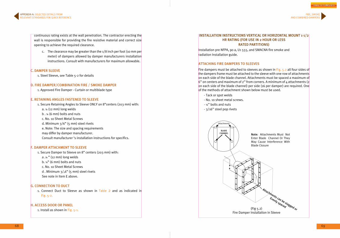
68 69
FIRE, SMOKE AND COMBINED DAMPERS
APPENDIx-A: SELECTED DETAILS FROM RELEVANT STANDARDS FOR QUICK REFERENCE
inSTALLATion inSTRUCTionS VERTiCAL oR HoRiZonTAL moUnT 1-1/2 HR RATinG (FoR USE in 2 HoUR oR LESS
RATED PARTiTionS)
Installation pre NFPA, 90 a, U1 555, and SMACNA fire smoke and radiation Installation guide.
ATTACHinG FiRE DAmPERS To SLEEVES
Fire dampers must be attached to sleeves as shown in Fig. 5.2 all four sides of the dampers frame must be attached to the sleeve with one row of attachments on each side of the blade channel. Attachments must be spaced a maximum of 6’’ on centers and maximum of 2’’ from corners. A minimum of 4 attachments (2 on each side of the blade channel) per side (16 per damper) are required. One of the methods of attachment shown below must be used.
- Tack or spot welds- No. 10 sheet metal screws.- ¼’’ bolts and nuts- 3/16’’ steel pop rivets
note: Attachments Must Not Enter Blade Channel Or They May Cause Interference With Blade Closure
Attachments
bLADECHAnnEL
Attachments can be stagged or
Evenly spaced
continuous rating exists at the wall penetration. The contractor erecting the wall is responsible for providing the fire resistive material and correct size opening to achieve the required clearance.
c. The clearance may be greater than the 1/8 inch per foot (10 mm per meter) of dampers allowed by damper manufacturers installation instructions. Consult with manufacturers for maximum allowable.
C. DAmPER SLEEVE1. Steel Sleeve, see Table 5-2 for details
D. FiRE DAmPER/CombinATion FiRE / SmoKE DAmPER1. Approved Fire Damper - Curtain or multiblade type
E. RETAininG AnGLES FASTEnED To SLEEVE1. Secure Retaining Angles to Sleeve ONLY on 8”centers (203 mm) with:
a. ½ (12 mm) long weldsb . ¼ (6 mm) bolts and nutsc. No. 10 Sheet Metal Screwsd. Minimum 3/6” (5 mm) steel rivetse. Note: The size and spacing requirementsmay differ by damper manufacturer.Consult manufacturer ‘s installation instructions for specifics.
F. DAmPER ATTACHmEnT To SLEEVE1. Secure Damper to Sleeve on 8” centers (203 mm) with:
a .½ ” (12 mm) long weldsb. ¼” (6 mm) bolts and nutsc. No. 10 Sheet Metal Screwsd . Minimum 3/,6” (5 mm) steel rivetsSee note in Item E above.
G. ConnECTion To DUCT1. Connect Duct to Sleeve as shown in Table 2 and as indicated in Fig. 5-2.
H. ACCESS DooR oR PAnEL1. Install as shown in Fig. 5-1. (Fig 5.2)
Fire Damper Installation in Sleeve
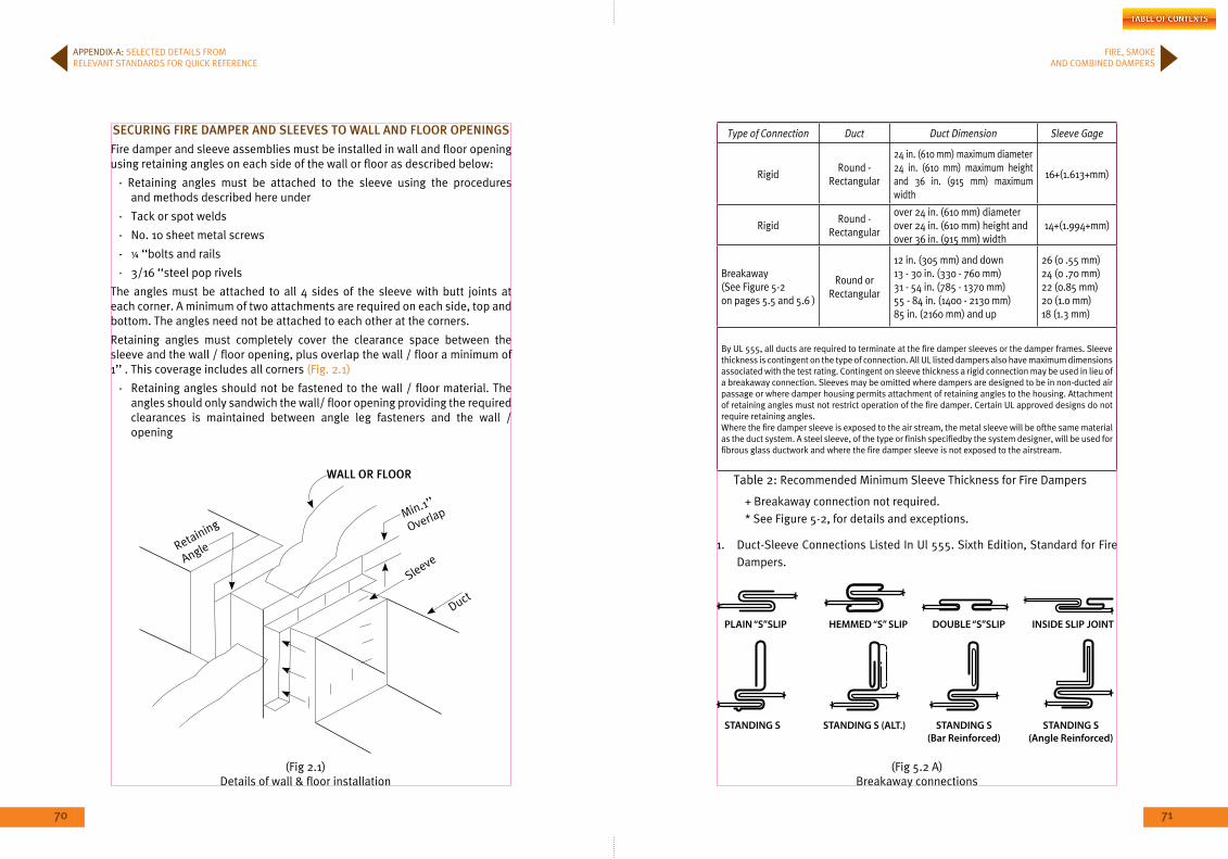
70 71
FIRE, SMOKE AND COMBINED DAMPERS
SECURinG FiRE DAmPER AnD SLEEVES To WALL AnD FLooR oPEninGS
Fire damper and sleeve assemblies must be installed in wall and floor opening using retaining angles on each side of the wall or floor as described below:
- Retaining angles must be attached to the sleeve using the procedures and methods described here under
- Tack or spot welds
- No. 10 sheet metal screws
- ¼ ‘‘bolts and rails
- 3/16 ‘‘steel pop rivels
The angles must be attached to all 4 sides of the sleeve with butt joints at each corner. A minimum of two attachments are required on each side, top and bottom. The angles need not be attached to each other at the corners.
Retaining angles must completely cover the clearance space between the sleeve and the wall / floor opening, plus overlap the wall / floor a minimum of 1’’ . This coverage includes all corners (Fig. 2.1)
- Retaining angles should not be fastened to the wall / floor material. The angles should only sandwich the wall/ floor opening providing the required clearances is maintained between angle leg fasteners and the wall / opening
WALL oR FLooR
Duct
SleeveRetaining
Angle
Min.1’’
Overlap
Type of Connection Duct Duct Dimension Sleeve Gage
RigidRound -
Rectangular
24 in. (610 mm) maximum diameter24 in. (610 mm) maximum height and 36 in. (915 mm) maximum width
16+(1.613+mm)
RigidRound -
Rectangular
over 24 in. (610 mm) diameterover 24 in. (610 mm) height andover 36 in. (915 mm) width
14+(1.994+mm)
Breakaway(See Figure 5-2on pages 5.5 and 5.6 )
Round orRectangular
12 in. (305 mm) and down13 - 30 in. (330 - 760 mm)31 - 54 in. (785 - 1370 mm)55 - 84 in. (1400 - 2130 mm)85 in. (2160 mm) and up
26 (0 .55 mm)24 (0 .70 mm)22 (0.85 mm)20 (1.0 mm)18 (1.3 mm)
By UL 555, all ducts are required to terminate at the fire damper sleeves or the damper frames. Sleeve thickness is contingent on the type of connection. All UL listed dampers also have maximum dimensions associated with the test rating. Contingent on sleeve thickness a rigid connection may be used in lieu of a breakaway connection. Sleeves may be omitted where dampers are designed to be in non-ducted air passage or where damper housing permits attachment of retaining angles to the housing. Attachment of retaining angles must not restrict operation of the fire damper. Certain UL approved designs do not require retaining angles.Where the fire damper sleeve is exposed to the air stream, the metal sleeve will be ofthe same material as the duct system. A steel sleeve, of the type or finish specifiedby the system designer, will be used for fibrous glass ductwork and where the fire damper sleeve is not exposed to the airstream.
+ Breakaway connection not required.* See Figure 5-2, for details and exceptions.
1. Duct-Sleeve Connections Listed In Ul 555. Sixth Edition, Standard for Fire Dampers.
APPENDIx-A: SELECTED DETAILS FROM RELEVANT STANDARDS FOR QUICK REFERENCE
(Fig 5.2 A)Breakaway connections
(Fig 2.1)Details of wall & floor installation
Table 2: Recommended Minimum Sleeve Thickness for Fire Dampers

72 73
FIRE, SMOKE AND COMBINED DAMPERS
2. Additional Duct-Sleeve Connections were tested by Smacna and Witnessed By UL In 1991. The Connections Performed Within The Requirements Of The UL Test Criteria.
3. Fasteners May Be Used As Follows. (A) Joints using connections shown in 5.3 below with a maximum of Two#10
sheet metal screws on each side and on the bottom located in the center of the Slip Pocket and penetrating both sides of the Slip Pocket.
FLAT DRiVE SLiP
(B) Joints using connectors of the type shown Fig. 5.3. Above on the top and the bottom and using flat drive Slips not exceeding 20 In. (510 mm) duct height on the sides (see sketch above).
(C) Joints where round or oval Spiral Ducts attach to round or oval collars which are part of the damper sleeve as shown below. #10 sheet metal screws are spaced equally around the circumference of the duct per the following:
Duct Diameters 22 in. (560 mm) and Smaller-3 Screws.Duct Diameters Over 22 in. (560 mm) To and Including 36 in.
(915 Mm)-5 Screws.notes:
(1) For flat oval ducts, the diameter shall be considered the largest (major) dimension of the duct.
(2) Duct sealant may be used as recommended by the damper manufacturer.
DAmPER/SLEEVE ASSEmbLiES WiTH CoLLARS FoR RoUnD AnD FLAT oVAL DUCTS
UL DUCT-SLEEVE ConnECTionS (bREAKAWAY ConnECTionS)
imPRoPER FiRE DAmPER inSTALLATionS
iTEm 1 Sealing of the fire damper retaining angles is not a requirement of an
approved damper installation. This detail is seldom specified by system designers and is virtually never included in the contractor’s pricing for the dampers on a project. If the local authority having jurisdiction mandates that the angles be sealed, contractors should issue a Request For Information (RFI) to design professionals such that the proper approved sealants be used. In no case should the retaining angles be sealed with any product not approved by the damper manufacturer including through Penetration Firestop products. Using unapproved products could be a violation of the damper manufacturer’s conditions of test and listing could void the UL listing ofthe damper and could render the damper inoperable.
iTEm 2 Introduction of any materials including mineral wool, ceramic fibres or
sealants of any kind into the required expansion space between the damper sleeve and fire partition has not been tested, has not been approved, and is not permitted by damper manufacturers. Doing so could be a violation of the manufacturer’s conditions oftest and listing, could void the UL listing of the damper and could render the damper inoperable. Indiscriminate and unnecessary deviations from standard fire damper installations should be avoided. Unless a deviation is specifically approved by the damper manufacturer, it could compromise the function for which the damper was ultimately installed.
APPENDIx-A: SELECTED DETAILS FROM RELEVANT STANDARDS FOR QUICK REFERENCE
(Fig 5.3) Flat Drive Slip
(Fig 10) Improper Fire Damper Installations
(Fig 9) Damper/Sleeve Assemblies with Collars for Round and Flat Oval Ducts
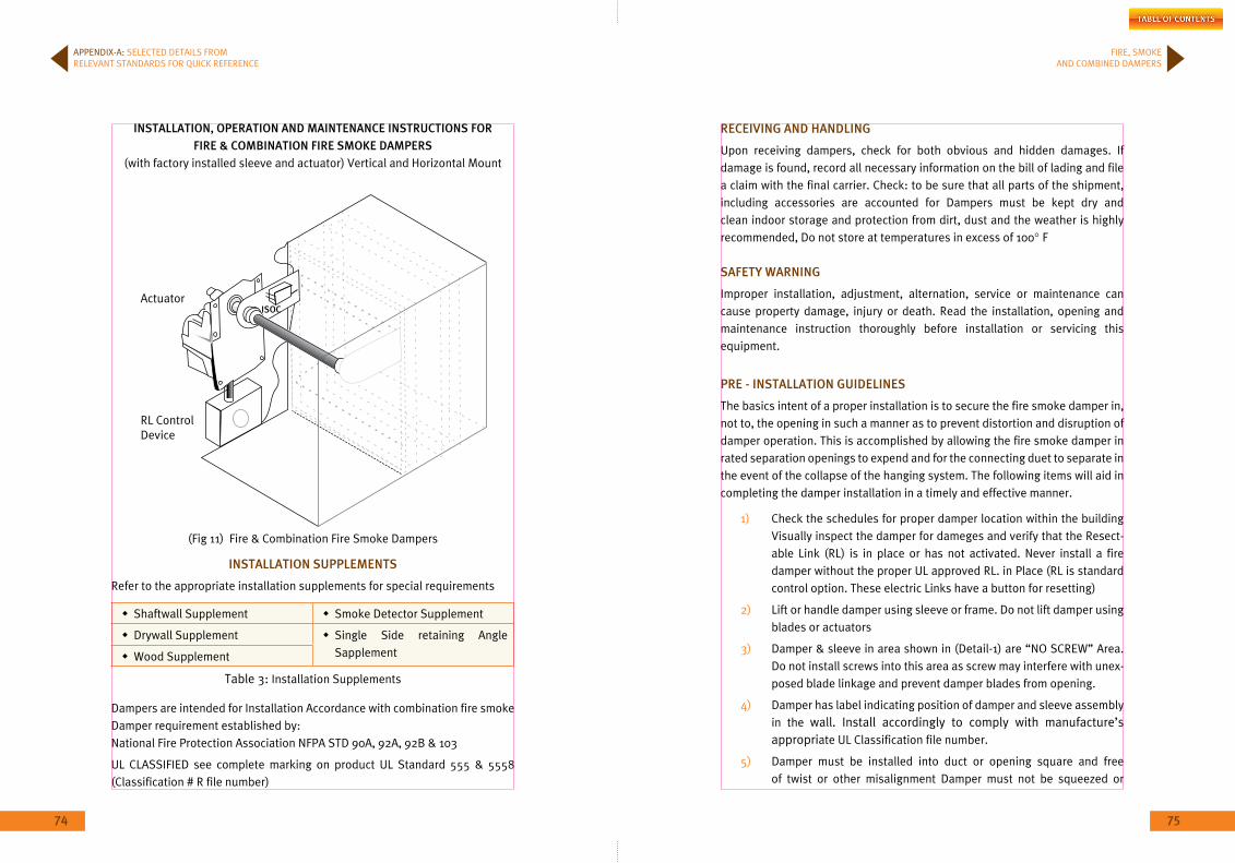
74 75
FIRE, SMOKE AND COMBINED DAMPERS
RECEiVinG AnD HAnDLinG
Upon receiving dampers, check for both obvious and hidden damages. If damage is found, record all necessary information on the bill of lading and file a claim with the final carrier. Check: to be sure that all parts of the shipment, including accessories are accounted for Dampers must be kept dry and clean indoor storage and protection from dirt, dust and the weather is highly recommended, Do not store at temperatures in excess of 100° F
SAFETY WARninG
Improper installation, adjustment, alternation, service or maintenance can cause property damage, injury or death. Read the installation, opening and maintenance instruction thoroughly before installation or servicing this equipment.
PRE - inSTALLATion GUiDELinES
The basics intent of a proper installation is to secure the fire smoke damper in, not to, the opening in such a manner as to prevent distortion and disruption of damper operation. This is accomplished by allowing the fire smoke damper in rated separation openings to expend and for the connecting duet to separate in the event of the collapse of the hanging system. The following items will aid in completing the damper installation in a timely and effective manner.
1) Check the schedules for proper damper location within the building Visually inspect the damper for dameges and verify that the Resect-able Link (RL) is in place or has not activated. Never install a fire damper without the proper UL approved RL. in Place (RL is standard control option. These electric Links have a button for resetting)
2) Lift or handle damper using sleeve or frame. Do not lift damper using blades or actuators
3) Damper & sleeve in area shown in (Detail-1) are “NO SCREW” Area. Do not install screws into this area as screw may interfere with unex-posed blade linkage and prevent damper blades from opening.
4) Damper has label indicating position of damper and sleeve assembly in the wall. Install accordingly to comply with manufacture’s appropriate UL Classification file number.
5) Damper must be installed into duct or opening square and free of twist or other misalignment Damper must not be squeezed or
inSTALLATion, oPERATion AnD mAinTEnAnCE inSTRUCTionS FoR FiRE & CombinATion FiRE SmoKE DAmPERS
(with factory installed sleeve and actuator) Vertical and Horizontal Mount
RL ControlDevice
iSoCActuator
inSTALLATion SUPPLEmEnTS
Refer to the appropriate installation supplements for special requirements
Shaftwall Supplement Smoke Detector Supplement
Drywall Supplement Single Side retaining Angle SapplementWood Supplement
Dampers are intended for Installation Accordance with combination fire smoke Damper requirement established by: National Fire Protection Association NFPA STD 90A, 92A, 92B & 103
UL CLASSIFIED see complete marking on product UL Standard 555 & 5558 (Classification # R file number)
APPENDIx-A: SELECTED DETAILS FROM RELEVANT STANDARDS FOR QUICK REFERENCE
(Fig 11) Fire & Combination Fire Smoke Dampers
Table 3: Installation Supplements
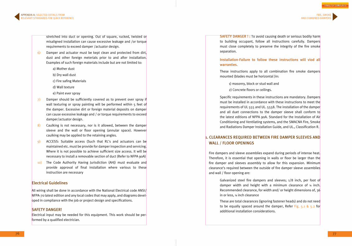
76 77
FIRE, SMOKE AND COMBINED DAMPERS
stretched into duct or opening. Out of square, rucked, twisted or misaligned installation can cause excessive leakage and /or torque requirements to exceed damper /actuator design.
6) Damper and actuator must be kept clean and protected from dirt, dust and other foreign meterials prior to and after installation. Examples of such foreign materials include but are not limited to:
a) Mother dust
b) Dry wall dust
c) Fire safing Materials
d) Wall texture
e) Paint ever spray
7) Damper should be sufficiently covered as to prevent over spray if wall texturing or spray painting will be performed within 5 feet of the damper. Excessive dirt or foreign material deposits on damper can cause excessive leakage and / or torque requirements to exceed damper/actuator design.
8) Caulking is not necessary, nor is it allowed, between the damper sleeve and the wall or floor opening (annular space). However caulking may be applied to the retaining angles.
9) ACCESS: Suitable access (Such that RL’s and actuators can be maintained etc. must be provide for damper inspection and servicing. Where it is not possible to achieve sufficient size access. It will be necessary to install a removable section of duct (Refer to NFPA 90A)
10) The Code Authority Having Jurisdiction (AHJ) must evaluate and provide approval of final installation where various to these instruction are necessary
Electrical Guidelines
All wiring shall be done in accordance with the National Electrical code ANSI/NFPA-70 latest edition and any local codes that may apply, and diagrams devel-oped in compliance with the job or project design and specifications.
SAFETY DAnGER!Electrical input may be needed for this equipment. This work should be per-formed by a qualified electrician.
SAFETY DAnGER ! : To avoid causing death or serious bodily harm to building occupant, follow all instructions carefully. Dampers must close completely to preserve the integrity of the fire smoke separation.
installation-Failure to follow these instructions will viod all warranties.
These instructions apply to all combination fire smoke dampers mounted (blades must be horizontal )in:
1) masonry, block or stud wall and
2) Concrete floors or ceilings.
Specific requirements in these instructions are mandatory. Dampers must be installed in accordance with these instructions to meet the requirements of UL 555 and UL. 5558. The installation of the damper and all duet connections to the damper sleeve shall conform to the latest editions of NFPA 90A. Standard for the Installation of Air Conditioning and Ventilating systems, and the SMACNA Fire, Smoke and Radiations Damper Installation Guide, and UL., Classification R.
1. CLEARAnCES REQUiRED bETWEEn FiRE DAmPER SLEEVES AnD WALL / FLooR oPEninGS
Fire dampers and sleeve assemblies expand during periods of intense heat. Therefore, it is essential that opening in walls or floor be larger than the fire damper and sleeves assembly to allow for this expansion. Minimum clearance’s required between the outside of fire damper sleeve assemblies and wall / floor opening are:
Galvanized steel fire dampers and sleeves; 1/8 inch, per foot of damper width and height with a minimum clearance of ¼ inch. Recommended clearance, for width and/ or height dimensions of, 36 in or less, ½ inch clearance
These are total clearances (ignoring fastener heads) and do not need to be equally spaced around the damper, Refer Fig. 5.1 & 5.2 for additional installation considerations.
APPENDIx-A: SELECTED DETAILS FROM RELEVANT STANDARDS FOR QUICK REFERENCE
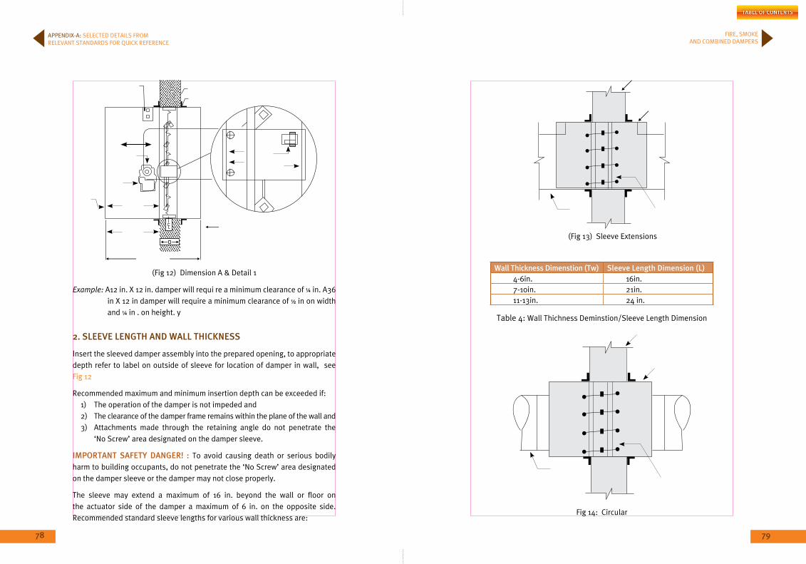
78 79
FIRE, SMOKE AND COMBINED DAMPERS
Wall Thickness Dimenstion (Tw) Sleeve Length Dimension (L)4-6in. 16in.7-10in. 21in.11-13in. 24 in.
Example: A12 in. x 12 in. damper will requi re a minimum clearance of ¼ in. A36 in x 12 in damper will require a minimum clearance of ½ in on width and ¼ in . on height. y
2. SLEEVE LEnGTH AnD WALL THiCKnESS
Insert the sleeved damper assembly into the prepared opening, to appropriate depth refer to label on outside of sleeve for location of damper in wall, see Fig 12
Recommended maximum and minimum insertion depth can be exceeded if:1) The operation of the damper is not impeded and 2) The clearance of the damper frame remains within the plane of the wall and 3) Attachments made through the retaining angle do not penetrate the
‘No Screw’ area designated on the damper sleeve.
imPoRTAnT SAFETY DAnGER! : To avoid causing death or serious bodily harm to building occupants, do not penetrate the ‘No Screw’ area designated on the damper sleeve or the damper may not close properly.
The sleeve may extend a maximum of 16 in. beyond the wall or floor on the actuator side of the damper a maximum of 6 in. on the opposite side. Recommended standard sleeve lengths for various wall thickness are:
APPENDIx-A: SELECTED DETAILS FROM RELEVANT STANDARDS FOR QUICK REFERENCE
(Fig 12) Dimension A & Detail 1
(Fig 13) Sleeve Extensions
Fig 14: Circular
Table 4: Wall Thichness Deminstion/Sleeve Length Dimension
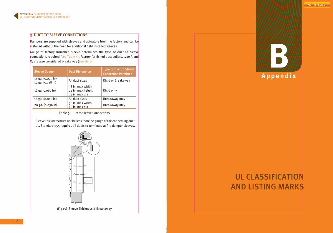
80 81
3. DUCT To SLEEVE ConnECTionS
Dampers are supplied with sleeves and actuators from the factory and can be installed without the need for additional field installed sleeves.
Gauge of factory furnished sleeve determines the type of duet to sleeve connections required (see Table 5). Factory furnished duct collars, type R and O, are also considered breakaway (see Fig.15)
Sleeve Gauge Duct DimensionType of Duct to Sleeve Connection Permitted
14 ga. (0.075 in)10 ga. (0.138 in)
All duct sizes Rigid or Breakaway
16 ga (0.060 in)36 in. max width24 in. max height24 in. max dia
Rigid only
16 ga. (0.060 in) All duct sizes Breakaway only
20 ga. (0.036 in)36 in. max width36 in. max dia
Breakaway only
Sleeve thickness must not be less than the gauge of the connecting duct. UL. Standard 555 requires all ducts to terminate at fire damper sleeves.
APPENDIx-A: SELECTED DETAILS FROM RELEVANT STANDARDS FOR QUICK REFERENCE
A p p e n d i x
B
UL CLASSiFiCATion AnD LiSTinG mARKS
Table 5: Duct to Sleeve Connections
(Fig 15) Sleeve Thickness & Breakaway
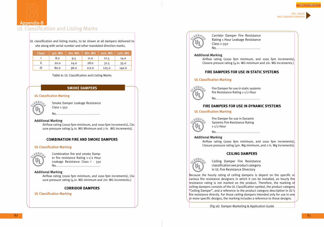
82
FIRE, SMOKE AND COMBINED DAMPERS
82
UL Classification and Listing Marks
UL classification and listing marks, to be shown at all dampers delivered to site along with serial number and other mandated direction marks.
Class 4in. WG 6in. WG 8in. WG 10in. WG 12in. WG
I 8.0 9.5 11.0 12.5 14.0
II 20.0 24.0 28.0 31.5 35.0
III 80.0 96.0 112.0 125.0 140.0
DAmPER mARKETinG & APPLiCATion GUiDE
SmOkE DAmpErS
UL Classification marking
Smoke Damper Leakage Resistance Class 1-350
No.. . . . . . . . . . . . . . . . . . . . . . . . . . . . . . . . .
Additional marking Airflow rating (2000 fpm minimum, and 1000 fpm increments), Clo-
sure pressure rating (4 in. WG Minimum and 2 in . WG Increments).
COmbINATION FIrE AND SmOkE DAmpErS
UL Classification marking
Combination fire and smoke Damp-er fire resistance Rating 1-1/2 Hour Leakage Resistance Class I - 350 No. . . . . . . . . . . . . . . . . . . . . . . . . . . . . . . . . .
Additional marking Airflow rating (2000 fpm minimum, and 1000 fpm increments), Clo-
sure pressure rating (4.in. WG minimum and 2in. WG increments.)
COrrIDOr DAmpErSUL Classification marking
Appendix-b
Corridor Damper Fire Resistance Rating 1 Hour Leakage Resistance Class 1-350 No. . . . . . . . . . . . . . . . . . . . . . . . . . . . . . . . . .
Additional marking Airflow rating (2000 fpm minimum, and 1000 fpm increments),
Closere presure rating (4.in. WG minimum and 2in. WG increments.)
FIrE DAmpErS FOr uSE IN STATIC SySTEmS
UL Classification marking
Fire Damper for use in static systems fire Resistance Rating 1-1/2 Hour
No.. . . . . . . . . . . . . . . . . . . . . . . . . . . . . . . . .
FIrE DAmpErS FOr uSE IN DyNAmIC SySTEmSUL Classification marking
Fire Damper for use in Dynamic Systems Fire Resistance Rating 1-1/2 Hour
No.. . . . . . . . . . . . . . . . . . . . . . . . . . . . . . . . .
Additional marking Airflow rating (2000 fpm minimum, and 1000 fpm increments),
Closure pressure rating (4in. Wg minimum, and 2 in. Wg Increments).
CEIlINg DAmpErS
Ceiling Damper Fire Resistance classification see product category in UL Fire Resistance Directory
Because the hourly rating of ceiling dampers is depent on the specific or various fire resistance designers in which it can be installed, an hourly fire resistance rating is not marked on the product. Therefore, the marking of ceiling dampers consists of the UL Classification symbol, the product category “Ceiling Damper”, and a reference to the product category description in UL’s fire resistance directly. For those ceiling dampers intended only for use in one or more specific designs, the marking includes a reference to those designs.
83
(Fig 16) Damper Marketing & Application Guide
Table 6: UL Classification and Listing Marks

84
APPENDIx-B: UL CLASSIFICATIONAND LISTING MARKS
A p p e n d i x
C
REFEREnCE STAnDARDS AnD DEFiniTionS
85
86 87
FIRE, SMOKE AND COMBINED DAMPERS
Reference Standards and DefinitionsC.1 STAnDARDS
ANSI / UL 263 - Standard for Building Construction Materials (ASTM E119, NFPA 252, UBC 7-1)
ASHRAE - American Society of Heating, Refrigerating and Air-Conditioning Engineers
NFPA - National Fire Protection Association
NFPA 70 - National Electrical Code
NFPA 72® - National Fire Alarm Code
NFPA 90A - Standard for the Installation of Air-Conditioning and Ventilating Systems
NFPA 92A - Recommended Practice for Smoke-Control Systems
NPFA 92B - Guide for Smoke Management Systems in Malls, Atria, and Large Areas
NFPA 101 - Life Safety Code / International Building Code
NFPA 110 - Standard for Emergency and Standby Power Systems
NFPA 221 - Standard for High Challenge Fire Walls, Fire Walls, and Fire Barrier Walls
SMACNA - Sheet Metal and Air Conditioning Contractors’ National Association
UL 555 - Standard for Fire Dampers
UL 555C - Standard for Ceiling Dampers
UL 555S - Standard for Smoke Dampers
C.2 DEFiniTionS
Approved: Acceptable to the authority having jurisdiction.
Authority Having Jurisdiction (AHJ): An organization, office, or individual responsible for enforcing the requirements of a code or standard, or for approving equipment, materials, an installation, or a procedure.
Compensated System: A system that adjusts for changing conditions either by modulating supply airflows or by relieving excess pressures.
Dedicated Smoke-Control System: Smoke-control systems and components that are installed for the sole purpose of providing smoke control, and upon activation these systems operate specifically to perform the smoke-control function.
Appendix-C
Design Pressure Difference: The desired pressure difference between the protected space and an adjacent space measured at the boundary of the protected space under a specified set of conditions with the smoke-control system operating.
End-to-End Verification : A self-testing method that provides positive confirmation that the desired result (e.g., airflow or damper position) has been achieved when a controlled device has been activated such as during smoke control, testing or manual override operations.
Fire Fighters’ Smoke-Control Station (FSCS): A system that provides graphical monitoring and manual overriding capability over smoke-control systems and equipment at designated location(s) within the building for the use of the fire department.
multiple-injection Pressurization System : A type of smoke-control system that has pressurization air supplied from multiple locations.
non-dedicated Smoke-Control Systems : Smoke-control systems and components that share components with some other system(s), such as the building HVAC system, and upon activation cause the HVAC system to change its mode of operation in order to achieve the smoke-control objectives.
Pressurized Stairwells: A type of smoke-control system in which stair shafts are mechanically pressurized, with respect to the fire area, with outdoor air to keep the smoke from contaminating them during a fire incidents.
Shall: Indicates a mandatory requirement.
Should: Indicates a recommendation or that which is advised but not required.
Single-injection Pressurization System: A type of smoke-control system that has pressurization air supplied from only one location.
Smoke: The airborne solid and liquid particulates and gases evolved when a Material undergoes combustion, together with the quantity of air that is entrained or otherwise mixed into the mass.
Smoke barrier: For the purposes of this standard, a continuous membrane, either vertical or horizontal such as a wall, floor, or ceiling assembly, that is designed and constructed to restrict the movement of smoke in conjunction with a smoke-control system.

88
APPENDIx-C: REFERENCE STANDARDS AND DEFINITIONS
Smoke-Control mode: A predefined operational configuration of a system or device for the purpose of smoke control.
Smoke-Control System: An engineered system that uses mechanical fans to produce pressure differences across smoke barriers to inhibit smoke movement.
Smoke-Control Zone: A space within a building enclosed by smoke barriers, including the top and bottom that is part of a zoned smoke-control system.
Smoke Exhaust System: A mechanical or gravity system intended to move smoke from the smoke zone to the exterior of the building, including smoke removal, purging and venting systems, as well as the function of exhaust fans utilized to reduce the pressure in a smoke zone.
Smoke Refuge Area: An area of the building separated from other spaces by fire resistance rated smoke barriers in which a tenable environment is maintained for the period Copyright NFPA of time that such areas might need to be occupied at the time of fire.
Smoke Zone: The smoke-control zone in which the fire is located.
Stack Effect: The vertical airflow within buildings caused by the temperature-created density differences between the building interior and exterior or between two interior spaces.
Tenable Environment: An environment in which smoke and heat are limited or otherwise restricted to maintain the impact on occupants to a level that is not life threatening.
Zoned Smoke-Control System: A smoke-control system that includes smoke exhaust for the smoke zone and pressurization for all contiguous smoke-control zones.
A p p e n d i x
D
inTERnATionAL STAnDARDS
89
91
FIRE, SMOKE AND COMBINED DAMPERS
90
International StandardsAppendix-D
nFPA 90A
DEFiniTionS
3.3.13.2 Combination Fire and Smoke Damper. A device that meets both the fire damper and smoke damper requirements.
3.3.13.3 Fire Damper: A device, installed in an air distribution system, designed to close automatically upon detection of heat, to interrupt migratory airflow, and to restrict the passage of flame. [221:1.5]
3.3.13.4 Smoke Damper: A device within the air distribution system to control the movement of smoke.
3.3.21 Plenum: A compartment or chamber to which one or more air ducts are connected and that forms part of the air distribution system.
3.3.22 Smoke: The airborne solid and liquid particulates and gases evolved when a material undergoes paralyses or combustion, together with the quantity of air that is entrained or otherwise mixed into the mass.
3.3.23 Smoke barrier: A continuous membrane either vertical or horizontal, such as a wall, floor or ceiling assembly that is designed and constructed to restrict the movement of smoke.
3.3.24 Smoke Control: A system that utilizes fans to produce pressure differences so as to manage smoke movement.
3.3.25*Smoke Detector: A device that senses visible or invisible particles of combustion.
nFPA 5000
8.4.2 opening Protectives
8.4.2.3:Fire dampers for ducts and air-transfer openings used as opening protective shall comply with the requirements of 8.8.8.
8.4.3 Penetrations : Penetrations in fire barrier walls shall comply with the requirements of Section 8.8.
8.4.4 Joints : Joints in fire barrier walls shall comply with the requirements of Section.
8.4.5.1: Fire barrier walls required by this Code shall be continuous from an outside wall to an outside wall, from a floor below to a floor or roof above, or from one fire barrier wall to another fire barrier wall, or a combination thereof.
8.6.2.3:Fire dampers for ducts and air-transfer openings used as opening protectives shall comply with the requirements of 8.8.8.
8.6.3 Penetrations: Penetrations in floor-ceiling and roof-ceiling assemblies shall comply with the requirements of Section 8.8.
8.6.5 Continuity: All floor-ceiling and roof-ceiling assemblies shall be continuous without openings or penetrations, except as provided by this chapter.
8.8.8.2 Fire Damper Requirements : Fire dampers shall be installed to protect ducts and air-transfer openings that penetrate fire barriers and fire walls as required by other sections of this Code. Fire dampers shall be designed and tested in accordance with the requirements of UL 555, Standard for Fire Dampers, and shall have the minimum fire protection rating specified in Table 8.8.8.2 for the rating of the assembly penetrated. In systems where fans continue to operate in the emergency mode, dynamic fire dampers shall be required.
8.8.8.2.1: Fire dampers shall be required in the following locations:
(1) Ducts and air-transfer openings penetrating walls or partitions having a fire resistance rating of 2 or more hours.
(2) Ducts and air-transfer openings penetrating shaft walls having a fire resistance rating of 1 or more hours.
(3) Ducts and air-transfer openings penetrating floors that are required to have protected openings where the duct also is not protected by a shaft enclosure.
(4) Air-transfer openings that occur in walls or partitions that are required to have a fire-resistive rating of 30 minutes or more.
5.3.2 Floors Required to Have a Fire Resistance Rating
5.3.2.1: Where air ducts extend through only one floor and serve only two adjacent stories, the air ducts shall be enclosed (See 5.3.4.1), or fire dampers shall be installed at each point where the floor is penetrated.
92 93
FIRE, SMOKE AND COMBINED DAMPERS
APPENDIx-D: INTERNATIONAL STANDARDS
5.3.2.2: Air ducts serving air-conditioning terminal devices on the floor above shall be permitted, provided a fire test conducted in accordance with NFPA 251, Standard Methods of Tests of Fire Endurance of Building Construction and Materials, determines that the fire resistance rating of the floor is maintained.
5.3.3* Floor or Roof-Ceiling Assemblies Having a Fire Resistance Rating
5.3.3.2 : Where dampers are required, see 5.4.4.
5.3.4 Shafts
5.3.4.1: Air ducts that pass through the floors of buildings that require the protection of vertical openings shall be enclosed with partitions or walls constructed of materials as permitted by the building code of the authority having jurisdiction, as indicated in 5.3.4.2 or 5.3.4.3, unless otherwise permitted by 5.3.4.3.1.
5.3.4.2: The shaft enclosure shall have a minimum fire resistance rating (based on possible fire exposure from either side of the partition or wall) of 1 hour where such air ducts are located in a building less than four stories in height.
5.3.4.3: The shaft enclosure shall have a minimum fire resistance rating (based on possible fire exposure from either side of the partition or wall) of 2 hours where such air ducts are located in a building four stories or more in height.
5.3.4.3.1: Where an air duct penetrates only one floor, or one floor and an air-handling equipment penthouse floor, and the air duct contains a fire damper located where the duct penetrates the floor, an air duct enclosure shall not be required.
5.3.4.4: A fire-resistive enclosure used as an air duct shall conform to 4.3.1 and 5.3.4.2 through 5.3.4.3.
5.3.4.4.1: Gypsum board systems shall be constructed in accordance with the Gypsum Association Fire Resistance Design Manual.
5.3.4.5: Shafts that constitute air ducts or that enclose air ducts used
for the movement of environmental air shall not enclose the following:
(1) Exhaust ducts used for the removal of smoke and grease-laden vapours from cooking equipment.
(2) Ducts used for the removal of flammable vapours.
(3) Ducts used for moving, conveying, or transporting stock, vapor or dust.
(4) Ducts used for the removal of non-flammable corrosive fumes and vapours.
(5) Refuse and linen chutes.
(6) Piping, except for non combustible piping conveying water or other non-hazardous or non-toxic materials.
(7) Combustible storage.
5.3.4.6: Fire dampers shall be installed at each direct or ducted opening into or out of enclosures required by 5.3.4.1, unless otherwise permitted by 5.3.4.6.1 or 5.3.4.6.2.
5.3.4.6.1: A fire damper shall not be required where an air duct system serving only one story is used only for exhaust of air to the outside and is contained within its own dedicated shaft.
5.3.4.6.2: A fire damper shall not be required where the following occur:
(1) Branch ducts connect to enclosed exhaust risers meeting the requirements of 5.3.4.1 or 5.3.4.4.
(2) The airflow moves upward.
(3) Steel sub-ducts at least 560 mm (22 in.) in length are carried up inside the riser from each inlet.
(4) The riser is appropriately sized to accommodate the flow restriction created by the sub-duct.
5.3.5 Smoke barriers
(1) Function as an engineered smoke-control system, including the provision of continuous air movement with the air-handling system.
(2) Provide air to other areas of the building during a fire emergency.
(3) Provide pressure differentials during a fire emergency.
5.3.5.1.2: Smoke dampers shall not be required to be located within a prescribed distance of a smoke barrier where isolation smoke dampers complying with 4.3.9.2 are used in air-handling equipment.

94 95
FIRE, SMOKE AND COMBINED DAMPERS
APPENDIx-D: INTERNATIONAL STANDARDS
5.3.5.1.3: Smoke dampers shall not be required where the air inlet or outlet openings in ducts are limited to a single smoke compartment.
5.3.5.1.4: Smoke dampers shall not be required in ducts where the air continues to move and the air-handling system installed is arranged to prevent recirculation of exhaust or return air under fire emergency conditions.
5.3.5.1.5: Smoke dampers shall not be required in health care occupancies where exempted by NFPA 101, Life Safety Code.
5.3.5.2: Where penetration of a smoke barrier is required to be provided with a fire damper, a combination fire and smoke damper equipped and arranged to be both smoke responsive and heat responsive shall be permitted.
5.4 Fire Dampers, Smoke Dampers, and Ceiling Dampers
5.4.1 Fire Dampers
5.4.1.1: Fire dampers used for the protection of openings in walls, partitions, or floors with fire resistance ratings of less than 3 hours shall have a 1½ hour fire protection rating in accordance with UL 555, Standard for Safety Fire Dampers.
5.4.2: Fire dampers used for the protection of openings in walls, partitions, or floors having a fire resistance rating of 3 hours or more shall have a 3-hour fire protection rating in accordance with UL 555, Standard for Safety Fire Dampers.
5.4.3 Smoke Dampers: Smoke dampers used for the protection of openings in smoke barriers or in engineered smoke-control systems shall be classified in accordance with UL 555S, Standard for Safety Smoke Dampers.
5.4.4 Ceiling Dampers
5.4.4.1: Ceiling dampers or other methods of protecting openings in rated floor or roof-ceiling assemblies shall comply with the construction details of the tested floor or roof-ceiling assembly or with listed ceiling air diffusers or listed ceiling dampers.
5.4.4.2: Ceiling dampers shall be tested in accordance with UL 555C, Standard for Safety Ceiling Dampers.
5.4.5 Damper Closure
5.4.5.1: All fire dampers and ceiling dampers shall close automatically.
5.4.5.1.1: All fire dampers and ceiling dampers shall remain closed upon the operation of a listed fusible link or other approved heat-actuated device located where readily affected by an abnormal rise of temperature in the air duct.
5.4.5.2 Fusible Links
5.4.5.2.1: Fusible links shall have a temperature rating approximately 28°C (50°F) above the maximum temperature that normally is encountered when the system is in operation or shut down.
5.4.5.2.2: Fusible links shall have a temperature rating not less than 71°C (160°F).
5.4.5.2.2.1 Where combination fire and smoke dampers are located within air ducts that are part of an engineered smoke-control system, fusible links or other approved heat-responsive devices shall have a temperature rating approximately 28°C (50°F) above the maximum smoke-control system designed operating temperature.
5.4.5.2.2.2 The combination fire and smoke dampers shall not exceed the UL 555S, Standard for Safety Smoke Dampers, degradation test temperature rating of the combination fire and smoke damper.
5.4.5.2.2.3 The combination fire and smoke dampers shall not exceed a maximum temperature rating of 177°C (350°F).
5.4.5.3: A provision for remote opening of combination fire and smoke dampers, where necessary for smoke removal, shall be permitted.
5.4.5.3.1: Combination fire and smoke dampers permitted in 5.4.5.3 shall have provisions that allow them to reclose automatically upon reaching the damper’s maximum degradation test temperature in accordance with UL 555S, Standard for Safety Smoke Dampers.
5.4.5.4: Dampers shall close against the maximum calculated airflow of that portion of the air duct system in which they are installed.

96 97
FIRE, SMOKE AND COMBINED DAMPERS
APPENDIx-D: INTERNATIONAL STANDARDS
5.4.5.4.1: Fire dampers shall be tested for closure in accordance with UL 555, Standard for Safety Fire Dampers.
5.4.5.4.2: Smoke dampers shall be tested for closure in accordance with UL 555S, Standard for Safety Smoke Dampers.
5.4.5.4.3: Combination fire and smoke dampers shall not be required to have provisions that allow them to reclose automatically where provisions for automatic fan or airflow shutdown, in the event of a fire, are provided.
5.4.6 installation
5.4.6.1: The locations and mounting arrangement of all fire dampers, smoke dampers, ceiling dampers, and fire protection means of a similar nature required by this standard shall be shown on the drawings of the air duct systems.
5.4.6.2* Fire dampers, including their sleeves, smoke dampers, and ceiling dampers shall be installed in accordance with the conditions of their listings and the manufacturer’s installation instructions.
5.4.6.3 The thickness of sleeves for fire dampers shall not be less than that associated with the conditions of rating required by Section 5.4.
5.4.6.3.1: Where UL 555, Standard for Safety Fire Dampers, permits sleeve thickness to be the same as that of the duct gauge, such thickness shall not be less than that specified in Table 7
Table 7 Minimum Sleeve Thickness Permitted in Accordance withUL 555
Air Duct Diameter or maximum Width minimum Sleeve Thickness
mm in. Gauge in.
305 12 or less 26 0.018
330–762 13–30 24 0.024
787–1372 31–54 22 0.030
1397–2134 55–84 20 0.036
2159 or more 85 or more 18 0.047
8.1 GEnERAL
8.1.1 Application
The features of fire protection set forth in this chapter apply to both new construction and existing buildings.
8.2 ConSTRUCTion AnD ComPARTmEnTATion
8.2.1* Construction
Buildings or structures occupied or used in accordance with the individual occupancy chapters (Chapters 12 through 42) shall meet the minimum construction requirements of those chapters. NFPA 220, Standard on Types of Building Construction, shall be used to determine the requirements for the construction classification. Where the building or facility includes additions or connected structures of different construction types, the rating and classification of the structure shall be based on either of the following:
(a) Separate buildings if a 2-hour or greater vertically-aligned fire barrier wall in accordance with NFPA 221, Standard for Fire Walls and Fire Barrier Walls, exists between the portions of the building.
Exception: The requirement of 8.2.1(1) shall not apply to previously approved separations between buildings.
(b) The least fire-resistive type of construction of the connected portions, if no such separation is provided.
8.2.2 Compartmentation
8.2.2.1: Where required by Chapters 12 through 42, every building shall be divided into compartments to limit the spread of fire and restrict the movement of smoke.
8.2.2.2: Fire compartments shall be formed with fire barriers that are continuous from outside wall to outside wall, from one fire barrier to another, or a combination thereof, including continuity through all concealed spaces, such as those found above a ceiling, including interstitial spaces. Walls used as fire barriers shall comply with Chapter 3 of NFPA 221, Standard for Fire Walls and Fire Barrier Walls. The NFPA 221 limitation on percentage width of openings shall not apply.Table 7: Minimum Thickness Permitted in Accordance with UL555
98 99
FIRE, SMOKE AND COMBINED DAMPERS
APPENDIx-D: INTERNATIONAL STANDARDS
Exception: A fire barrier required for an occupied space below an interstitial space shall not be required to extend through the interstitial space, provided that the construction assembly forming the bottom of the interstitial space has a fire resistance rating not less than that of the fire barrier.
8.2.3 Fire barriers
8.2.3.1 Fire Resistance-Rated Assemblies
8.2.3.1.1: Floor-ceiling assemblies and walls used as fire barriers, including supporting construction, shall be of a design that has been tested to meet the conditions of acceptance of NFPA 251, Standard Methods of Tests of Fire Endurance of Building Construction and Materials. Fire barriers shall be continuous in accordance with 8.2.2.2.
Exception no.1: Structural elements shall be required to have only the fire resistance rating required for the construction classification of the building where such elements support non-bearing wall or partition assemblies having a required fire resistance rating of 1 hour or less and where such elements do not serve as exit enclosures or protection for vertical openings.
Exception no. 2*: This requirement shall not apply to assemblies calculated to have equivalent fire resistance, provided that the calculations are based on the conditions of acceptance and the fire exposure specified in NFPA 251, Standard Methods of Tests of Fire Endurance of Building Construction and Materials.
Exception no. 3: This requirement shall not apply to structural elements supporting floor assemblies in accordance with the exception to 18.1.6.2.
8.2.3.1.2 Fire barriers used to provide enclosure, subdivision, or protection under this Code shall be classified in accordance with one of the following fire resistance ratings:
(1) 2-hour fire resistance rating.
(2) 1-hour fire resistance rating.
(3)* 1/2-hour fire resistance rating.
8.2.3.2 Fire Protection-Rated opening Protective
8.2.3.2.1 Door assemblies in fire barriers shall be of an approved type with the appropriate fire protection rating for the location in which they are installed and shall comply with the following:
(1)* Fire doors shall be installed in accordance with NFPA 80, Standard for Fire Doors and Fire Windows. Fire doors shall be of a design that has been tested to meet the conditions of acceptance of NFPA 252, Standard Methods of Fire Tests of Door Assemblies.
Exception: The requirement of 8.2.3.2.1(a) shall not apply where otherwise specified by 8.2.3.2.3.1.
(2) Fire doors shall be self-closing or automatic-closing in accordance with 7.2.1.8 and, where used within the means of egress, shall comply with the provisions of 7.2.1.
8.2.3.2.2 Fire window assemblies shall be permitted in fire barriers having a required fire resistance rating of 1 hour or less and shall be of an approved type with the appropriate fire protection rating for the location in which they are installed. Fire windows shall be installed in accordance with NFPA 80, Standard for Fire Doors and Fire Windows, and shall comply with the following:
(1) Fire windows used in fire barriers, other than existing fire window installations of wired glass and other fire-rated glazing material in approved metal frames, shall be of a design that has been tested to meet the conditions of acceptance of NFPA 257, Standard on Fire Test for Window and Glass Block Assemblies.
(2) Fire windows used in fire barriers, other than existing fire window installations of wired glass and other fire-rated glazing material in approved metal frames, shall not exceed 25 percent of the area of the fire barrier in which they are used.
Exception: Fire-rated glazing material shall be permitted to be installed in approved existing frames.
8.2.3.2.3* opening Protective
8.2.3.2.3.1 Every opening in a fire barrier shall be protected to limit the spread of fire and restrict the movement of smoke from one side of the fire barrier to the other. The fire
100 101
FIRE, SMOKE AND COMBINED DAMPERS
APPENDIx-D: INTERNATIONAL STANDARDS
protection rating for opening protective shall be as follows:
(1) 2-hour fire barrier -11/2-hour fire protection rating.
(2) 1-hour fire barrier - 1-hour fire protection rating where used or vertical openings or exit enclosures, or 3/4-hour fire protection rating where used for other than vertical openings or exit enclosures, unless a lesser fire protection rating is specified by Chapter 7 or Chapters 11 through 42.
Exception no. 1: Where the fire barrier specified in 8.2.3.2.3.1(2) is provided as a result of a requirement that corridor walls or smoke barriers be of 1-hour fire resistance-rated construction, the opening protective shall be permitted to have not less than a 20-minute fire protection rating when tested in accordance with NFPA 252, Standard Methods of Fire Tests of Door Assemblies, without the hose stream test.
Exception no. 2: The requirement of 8.2.3.2.3.1(2) shall not apply where special requirements for doors in 1-hour fire resistance-rated corridor walls and 1-hour fire resistance-rated smoke barriers are specified in Chapters 18 through 21.
Exception no. 3: Existing doors having a 3/4-hour fire protection rating shall be permitted to continue to be used in vertical openings and in exit enclosures in lieu of the 1-hour rating required by 8.2.3.2.3.1(2).
(3) 1/2-hour fire barrier - 20-minute fire protection rating.
Exception: Twenty-minute fire protection-rated doors shall be exempt from the hose stream test of NFPA 252, Standard Methods of Fire Tests of Door Assemblies.
8.2.3.2.3.2: Where a 20-minute fire protection-rated door is required in existing buildings, an existing 13/4 in. (4.4 cm) solid, bonded wood-core door, or an existing steel-clad (tin-clad) wood door, or an existing solid-core steel door with positive latch and closer shall be permitted.
Exception: This requirement shall not apply where otherwise specified by Chapters 11 through 42.
8.2.3.2.4 Penetrations and Miscellaneous Openings in Fire Barriers
8.2.3.2.4.1* Openings in fire barriers for air-handling ductwork or air movement shall be protected in accordance with 9.2.1.
8.2.3.2.4.2* Pipes, conduits, bus ducts, cables, wires, air ducts, pneumatic tubes and ducts, and similar building service equipment that pass through fire barriers shall be protected as follows:
(1) The space between the penetrating item and the fire barrier shall meet one of the following conditions:
(a) It shall be filled with a material that is capable of maintaining the fire resistance of the fire barrier.
(b) It shall be protected by an approved device that is designed for the specific purpose.
(2) Where the penetrating item uses a sleeve to penetrate the fire barrier, the sleeve shall be solidly set in the fire barrier, and the space between the item and the sleeve shall meet one of the following conditions:
(a) It shall be filled with a material that is capable of maintaining the fire resistance of the fire barrier.
(b) It shall be protected by an approved device that is designed for the specific purpose.
(3) Insulation and coverings for pipes and ducts shall not pass through the fire barrier unless one of the following conditions is met:
(a) The material shall be capable of maintaining the fire resistance of the fire barrier.
(b) The material shall be protected by an approved device that is designed for the specific purpose.
(4) Where designs take transmission of vibration into consideration, any vibration isolation shall meet one of the following conditions:
(a) It shall be made on either side of the fire barrier.
(b) It shall be made by an approved device that is designed for the specific purpose.
8.2.4 Smoke Partitions
8.2.4.1 Where required elsewhere in this Code, smoke partitions shall be provided to limit the transfer of smoke.
8.2.4.2 Smoke partitions shall extend from the floor to the underside of the floor or roof deck above, through any concealed spaces,
102 103
FIRE, SMOKE AND COMBINED DAMPERS
APPENDIx-D: INTERNATIONAL STANDARDS
such as those above suspended ceilings, and through interstitial structural and mechanical spaces.
Exception*: Smoke partitions shall be permitted to terminate at the underside of a monolithic or suspended ceiling system where the following conditions are met:
(1) The ceiling system forms a continuous membrane.
(2) A smoke tight joint is provided between the top of the smoke partition and the bottom of the suspended ceiling.
(3) The space above the ceiling is not used as a plenum.
8.2.4.3 Doors
8.2.4.3.1 Doors in smoke partitions shall comply with 8.2.4.3.2 through 8.2.4.3.5.
8.2.4.3.2 Doors shall comply with the provisions of 7.2.1.
8.2.4.3.3 Doors shall not include louvers.
8.2.4.3.4* Door clearances shall be in accordance with NFPA 80, Standard for Fire Doors and Fire Windows.
8.2.4.3.5 Doors shall be self-closing or automatic-closing in accordance with 7.2.1.8.
8.2.4.4 Penetrations and miscellaneous openings in Smoke Partitions
8.2.4.4.1 Pipes, conduits, bus ducts, cables, wires, air ducts, pneumatic tubes and ducts, and similar building service equipment that pass through smoke partitions shall be protected as follows:
(1) The space between the penetrating item and the smoke partition shall meet one of the following conditions:
(a) It shall be filled with a material that is capable of limiting the transfer of smoke.
(b) It shall be protected by an approved device that is designed for the specific purpose.
(2) Where the penetrating item uses a sleeve to penetrate the smoke partition, the sleeve shall be solidly set in the smoke partition, and the space between the item and the sleeve shall meet one of the following conditions:
(a) It shall be filled with a material that is capable of limiting the transfer of smoke.
(b) It shall be protected by an approved device that is designed for the specific purpose.
(3) Where designs take transmission of vibrations into consideration, any vibration isolation shall meet one of the following conditions:
(a) It shall be made on either side of the smoke partitions.
(b) It shall be made by an approved device that is designed for the specific purpose.
8.2.4.4.2 Openings located at points where smoke partitions meet the outside walls, other smoke partitions, smoke barriers, or fire barriers of a building shall meet one of the following conditions:
(1) They shall be filled with a material that is capable of limiting the transfer of smoke.
(2) They shall be made by an approved device that is designed for the specific purpose.
8.2.4.4.3* Air transfer openings in smoke partitions shall be provided with approved dampers designed to limit the transfer of smoke. Dampers in air transfer openings shall close upon detection of smoke by approved smoke detectors installed in accordance with NFPA 72, National Fire Alarm Code.
8.2.5 Vertical openings
8.2.5.1 Every floor that separates stories in a building shall be constructed as a smoke barrier to provide a basic degree of compartmentation. (See 3.3.182 for definition of Smoke)
Exception: This requirement shall not apply where otherwise specified by 8.2.5.5, 8.2.5.6, or Chapters 11 through 42.
8.2.5.2*Openings through floors, such as stairways, hoist ways for elevators, dumbwaiters, and inclined and vertical conveyors; shaft ways used for light, ventilation, or building services; or expansion joints and seismic joints used to allow structural movements shall be enclosed with fire barrier walls. Such enclosures shall be continuous from floor to floor or floor to roof. Openings shall be protected as appropriate for the fire resistance rating of the barrier.
104 105
FIRE, SMOKE AND COMBINED DAMPERS
APPENDIx-D: INTERNATIONAL STANDARDS
Exception no.1: This requirement shall not apply where otherwise specified by 8.2.5.5, 8.2.5.6, 8.2.5.7, or Chapters 11 through 42.
Exception no. 2: This requirement shall not apply to escalators and moving walks protected in accordance with 8.2.5.11.
Exception no. 3: This requirement shall not apply to expansion or seismic joints designed to prevent the penetration of fire and shown to have a fire resistance rating of not less than the required fire resistance rating of the floor when tested in accordance with ANSI/UL 2079, Test of Fire Resistance of Building Joint Systems.
Exception no. 4: Enclosure shall not be required for pneumatic tube conveyors protected in accordance with 8.2.3.2.4.2.
Exception no. 5: This requirement shall not apply to existing mail chutes where one of the following conditions is met:
(1) The cross-sectional area does not exceed 16 inch2 (103 cm2).
(2) The building is protected throughout by an approved automatic sprinkler system in accordance with Section 9.7.
8.2.5.3 Vertical openings (shafts) that do not extend to the bottom or the top of the building or structure shall be enclosed at the lowest or highest level of the shaft, respectively, with construction in accordance with 8.2.5.4.
Exception: Shafts shall be permitted to terminate in a room or space having a use related to the purpose of the shaft, provided that the room or space is separated from the remainder of the building by construction having a fire resistance rating and opening protective in accordance with 8.2.5.4 and 8.2.3.2.3.
8.2.5.4 The fire resistance rating for the enclosure of floor openings shall be not less than as follows (see 7.1.3.2.1 for enclosure of exits):
(1) Enclosures connecting four stories or more in new construction-2-hour fire barriers.
(2) Other enclosures in new construction -1-hour fire barriers.
(3) Existing enclosures in existing buildings -1/2-hour fire barriers.
(4) As specified in Chapter 26 for lodging and rooming houses, in Chapter 28 for new hotels, and in Chapter 30 for new apartment buildings.
8.2.5.5 Unless prohibited by Chapters 12 through 42, unenclosed floor
openings forming a communicating space between floor levels shall be permitted, provided that the following conditions are met:
(1) The communicating space does not connect more than three contiguous stories.
(2) The lowest or next to lowest story within the communicating space is a street floor.
(3) The entire floor area of the communicating space is open and unobstructed such that a fire in any part of the space will be readily obvious to the occupants of the space prior to the time it becomes an occupant hazard.
(4) The communicating space is separated from the remainder of the building by fire barriers with not less than a 1-hour fire resistance rating.
Exception no.1: In buildings protected throughout by an approved automatic sprinkler system in accordance with Section 9.7, a smoke barrier in accordance with Section 8.3 shall be permitted to serve as the separation required by 8.2.5.5(4).
Exception no. 2: The requirement of 8.2.5.5(4) shall not apply to fully sprinkled residential housing units of detention and correctional occupancies in accordance with Exception No. 2 to 22.3.1.1 and Exception No. 2 to 23.3.1.1.
(5) The communicating space has ordinary hazard contents protected throughout by an approved automatic sprinkler system in accordance with Section 9.7 or has only low hazard contents. (See 6.2.2.)
(6) Egress capacity is sufficient to provide for all the occupants of all levels within the communicating space to simultaneously egress the communicating space by considering it as single floor area in determining the required egress capacity.
(7) Each occupant within the communicating space has access to not less than one exit without having to traverse another story within the communicating space.
(8) Each occupant not in the communicating space has access to not less than one exit without having to enter the communicating space.
106 107
FIRE, SMOKE AND COMBINED DAMPERS
APPENDIx-D: INTERNATIONAL STANDARDS
8.2.5.6*Unless prohibited by Chapters 12 through 42, an atrium shall be permitted, provided that the following conditions are met:
(1) In other than existing, previously approved atria, atriums are separated from the adjacent spaces by fire barriers with not less than a 1-hour fire resistance rating with opening protective for corridor walls. (See 8.2.3.2.3.1(2), Exception No. 1.)
Exception No. 1: Any number of levels of the building shall be permitted to open directly to the atrium without enclosure based on the results of the engineering analysis required in 8.2.5.6(5).
Exception no. 2*: Glass walls and inoperable windows shall be permitted in lieu of the fire barriers where automatic sprinklers are spaced along both sides of the glass wall and the inoperable window at intervals not to exceed 6 ft (1.8 m). The automatic sprinklers shall be located at a distance from the glass not to exceed 1 ft (0.3 m) and shall be arranged so that the entire surface of the glass is wet upon operation of the sprinklers. The glass shall be tempered, wired, or laminated glass held in place by a gasket system that allows the glass framing system to deflect without breaking (loading) the glass before the sprinklers operate. Automatic sprinklers shall not be required on the atrium side of the glass wall and the inoperable windows where there is no walkway or other floor area on the atrium side above the main floor level. Doors in such walls shall be glass or other material that resists the passage of smoke. Doors shall be self-closing or automatic-closing upon detection of smoke.
(2) Access to exits is permitted to be within the atrium, and exit discharge in accordance with 7.7.2 is permitted to be within the atrium.
(3) The occupancy within the space meets the specifications for classification as low or ordinary hazard contents. (See 6.2.2.)
(4) The entire building is protected throughout by an approved and supervised automatic sprinkler system in accordance with Section 9.7.
(5) For other than existing, previously approved atria, an engineering analysis is performed that demonstrates that the building is designed to keep the smoke layer interface above the
highest unprotected opening to adjoining spaces, or 6 ft (1.85 m) above the highest floor level of exit access open to the atrium for a period equal to 1.5 times the calculated egress time or 20 minutes, whichever is greater.
(6) In other than existing, previously approved atria, where an Engineered smoke control system is installed to meet the requirements of 8.2.5.6(5), the system is independently activated by each of the following:
(a) The required automatic sprinkler system.
(b) Manual controls that are readily accessible to the fire department.
8.2.5.7 A vertical opening serving as other than an exit enclosure, connecting only two adjacent stories, and piercing only one floor shall be permitted to be open to one of the two stories.
8.2.5.8 Where permitted by Chapters 12 through 42, unenclosed vertical openings not concealed within the building construction shall be permitted as follows:
(1) Such openings shall connect not more than two adjacent stories (one floor pierced only).
(2) Such openings shall be separated from unprotected vertical openings serving other floors by a barrier complying with 8.2.5.4.
(3) Such openings shall be separated from corridors.
(4) Such openings shall not serve as a required means of egress.
8.2.5.9 Where there are three or fewer elevator cars in a building, they shall be permitted to be located within the same hoist way enclosure. Where there are four elevator cars, they shall be divided in such a manner that not less than two separate hoist way enclosures are provided. Where there are more than four elevator cars, the number of elevator cars located within a single hoist way enclosure shall not exceed four.
Exception: This requirement shall not apply to existing hoist ways in existing buildings.
8.2.5.10 Service openings for conveyors, elevators, and dumbwaiters,
108 109
FIRE, SMOKE AND COMBINED DAMPERS
APPENDIx-D: INTERNATIONAL STANDARDS
where required to be open on more than one story at the same time for purposes of operation, shall be provided with closing devices in accordance with 7.2.1.8.
8.2.5.11 Any escalators or moving walks serving as a required exit in existing buildings shall be enclosed in the same manner as exit stairways. (See 7.2.7.)
8.2.5.12 Moving walks not constituting an exit and escalators, other than escalators in large open areas such as atriums and enclosed shopping malls, shall have their floor openings enclosed or protected as required for other vertical openings.
Exception no. 1*: In buildings protected throughout by an approved automatic sprinkler system in accordance with Section 9.7, escalators or moving walk openings shall be permitted to be protected in accordance with the method detailed in NFPA 13, Standard for the Installation of Sprinkler Systems, or in accordance with a method approved by the authority having jurisdiction.
Exception no. 2: Escalators shall be permitted to be protected in accordance with 8.2.5.13.
8.2.5.13 In buildings protected throughout by an approved automatic sprinkler system in accordance with Section 9.7, escalators or moving walk openings shall be permitted to be protected by rolling steel shutters appropriate for the fire resistance rating of the vertical opening protected. The shutters shall close automatically and independently of each other upon smoke detection and sprinkler operation. There shall be a manual means of operating and testing the operation of the shutter. The shutters shall be operated not less than once a week to ensure that they remain in proper operating condition. The shutters shall operate at a speed not to exceed 30 ft/min (0.15 m/s) and shall be equipped with a sensitive leading edge. The leading edge shall arrest the progress of a moving shutter and cause it to retract a distance of approximately 6 in. (15.2 cm) upon the application of a force not exceeding 20 lbf (90 N) applied to the surface of the leading edge. The shutter, following this retraction, shall continue to close. The operating
mechanism for the rolling shutter shall be provided with standby power complying with the provisions of NFPA 70, National Electrical Code.
8.2.6 mezzanines
8.2.6.1 General : A mezzanine shall not be included as a story for the purpose of determining the allowable number of stories in a building.
Exception: Multilevel residential housing areas in detention and correctional occupancies in accordance with Chapters 22 and 23 shall be exempt from the provisions of 8.2.6.2 and 8.2.6.3.
8.2.6.2 Area Limitations
8.2.6.2.1 The aggregate area of mezzanines within a room, other than those located in special purpose industrial occupancies, shall not exceed one-third the open area of the room in which the mezzanines are located. Enclosed space shall not be included in a determination of the size of the room in which the mezzanine is located.
8.2.6.2.2 There shall be no limit on the number of mezzanines in a room.
8.2.6.2.3 For purposes of determining the allowable mezzanine area, the area of the mezzanines shall not be included in the area of the room.
8.2.6.3 openness: All portions of a mezzanine, other than walls not more than 42 in. (107 cm) high, columns, and posts, shall be open to and unobstructed from the room in which the mezzanine is located, unless the occupant load of the aggregate area of the enclosed space does not exceed 10.
Exception: A mezzanine having two or more means of egress shall not be required to open into the room in which it is located if not less than one of the means of egress provides direct access from the enclosed area to an exit at the mezzanine level.
8.2.7 Concealed Spaces
8.2.7.1 In new Type III, Type IV, or Type V construction, any concealed space in which materials having a flame spread rating greater than Class A (as defined in Section 10.2) are exposed shall be
110 111
FIRE, SMOKE AND COMBINED DAMPERS
APPENDIx-D: INTERNATIONAL STANDARDS
effectively fire stopped or draft stopped as follows:
(1) Every exterior and interior wall and partition shall be fire-stopped at each floor level, at the top story ceiling level, and at the level of support for roofs.
(2) Every unoccupied attic space shall be subdivided by draft stops into areas not to exceed 3000 ft2 (280 m2).
(3) Any concealed space between the ceiling and the floor or roof above shall be draft stopped for the full depth of the space along the line of support for the floor or roof structural members and, if necessary, at other locations to form areas not to exceed 1000 ft2 (93 m2) for any space between the ceiling and floor and 3000 ft2 (280 m2) for any space between the ceiling and roof.
Exception no. 1: This requirement shall not apply where the space is protected throughout by an approved automatic sprinkler system in accordance with Section 9.7.
Exception no. 2: This requirement shall not apply to concealed spaces serving as plenums. (See NFPA 90A, Standard for the Installation of Air-Conditioning and Ventilating Systems.)
8.2.7.2 In every existing building, fire stopping and draft stopping shall be provided as required by the provisions of Chapters 12 through 42.
8.3 SmoKE bARRiERS
8.3.1 General.
Where required by Chapters 12 through 42, smoke barriers shall be provided to subdivide building spaces for the purpose of restricting the movement of smoke.
8.3.2 Continuity.
Smoke barriers required by this Code shall be continuous from an outside wall to an outside wall, from a floor to a floor, or from a smoke barrier to a smoke barrier or a combination thereof. Such barriers shall be continuous through all concealed spaces, such as those found above a ceiling, including interstitial spaces.
Exception: A smoke barrier required for an occupied space below an interstitial space shall not be required to extend through the
interstitial space, provided that the construction assembly forming the bottom of the interstitial space provides resistance to the passage of smoke equal to that provided by the smoke barrier.
8.3.3 Fire barrier Used as Smoke barrier
A fire barrier shall be permitted to be used as a smoke barrier, provided that it meets the requirements of 8.3.4 through 8.3.6.
8.3.4 Doors.
8.3.4.1 Doors in smoke barriers shall close the opening leaving only the minimum clearance necessary for proper operation and shall be without undercuts, louvers, or grilles.
8.3.4.2 Where a fire resistance rating for smoke barriers is specified elsewhere in the Code, openings shall be protected as follows:
(1) Door opening protective shall have a fire protection rating of not less than 20 minutes where tested in accordance with NFPA 252, Standard Methods of Fire Tests of Door Assemblies, without the hose stream test, unless otherwise specified by Chapters 12 through 42.
(2) Fire windows shall comply with 8.2.3.2.2.
Exception: Latching hardware shall not be required on doors in smoke barriers where so indicated by Chapters 12 through 42.
8.3.4.3 Doors in smoke barriers shall be self-closing or automatic-closing in accordance with 7.2.1.8 and shall comply with the provisions of 7.2.1.
8.3.5 Smoke Dampers
8.3.5.1 An approved damper designed to resist the passage of smoke shall be provided for each air transfer opening or duct penetration of a required smoke barrier, unless otherwise specifically exempted by Chapters 12 through 42.
Exception no.1: This requirement shall not apply to ducts or air transfer openings that are part of an engineered smoke control system in accordance with Section 9.3.
Exception no.2: This requirement shall not apply to ducts where the

112 113
FIRE, SMOKE AND COMBINED DAMPERS
APPENDIx-D: INTERNATIONAL STANDARDS
air continues to move and the air-handling system installed is arranged to prevent recirculation of exhaust or return air under fire emergency conditions.
Exception no. 3: This requirement shall not apply where the air inlet or outlet openings in ducts are limited to a single smoke compartment.
Exception no. 4: This requirement shall not apply where ducts penetrate floors that serve as smoke barriers.
8.3.5.2 Required smoke dampers in ducts penetrating smoke barriers shall close upon detection of smoke by approved smoke detectors in accordance with NFPA 72, National Fire Alarm Code.
Exception no. 1: Duct detectors shall not be required where ducts penetrate smoke barriers above the smoke barrier doors and the door release detector actuates the damper.
Exception no. 2: Approved smoke detector installations located within the ducts in existing installations shall be exempt from the requirements of NFPA 72, National Fire Alarm Code.
8.3.5.3 Required smoke dampers in air transfer openings shall close upon detection of smoke by approved smoke detectors in accordance with NFPA 72, National Fire Alarm Code.
Exception: Where a duct is provided on one side of the smoke barrier, the smoke detectors on the duct side shall be in accordance with 8.3.5.2.
8.3.6 Penetrations and miscellaneous openings in Floors and Smoke
barriers
8.3.6.1 Pipes, conduits, bus ducts, cables, wires, air ducts, pneumatic
tubes and ducts, and similar building service equipment that pass through floors and smoke barriers shall be protected as follows:
(1) The space between the penetrating item and the smoke barrier shall meet one of the following conditions:
(a) It shall be filled with a material that is capable of maintaining the smoke resistance of the smoke barrier.
(b) It shall be protected by an approved device that is designed for the specific purpose.
(2) Where the penetrating item uses a sleeve to penetrate the smoke barrier, the sleeve shall be solidly set in the smoke barrier, and the space between the item and the sleeve shall meet one of the following conditions:
(a) It shall be filled with a material that is capable of maintaining the smoke resistance of the smoke barrier.
(b) It shall be protected by an approved device that is designed for the specific purpose.
(3) Where designs take transmission of vibration into consideration, any vibration isolation shall meet one of the following conditions:
(a) It shall be made on either side of the smoke barrier.
(b) It shall be made by an approved device that is designed for the specific purpose.
8.3.6.2 Openings occurring at points where floors or smoke barriers meet the outside walls, other smoke barriers, or fire barriers of a building shall meet one of the following conditions:
(1) It shall be filled with a material that is capable of maintaining the smoke resistance of the floor or smoke barrier.
(2) It shall be protected by an approved device that is designed for the specific purpose.

114
A p p e n d i x
E
inSPECTion FoRm SAmPLE
115

116
Inspection Form SampleAppendix-E
FiR
E D
Am
PER
TES
T R
EPo
RT
(1)
PRo
JECT
:PE
Rm
iT n
o.:
inS
TALL
inG
Co
nTR
ACT
oR
DA
TE:
inS
PECT
oR
SH
EET
ofSh
op
Dra
win
g N
o.F.
D.
No.
F.D
.Si
zeR
etai
ning
A
ngle
sB
reak
away
Jo
ints
Doo
r &A
cces
sibi
lity
F.D
. Lin
k A
c-ce
sibi
lity
Blad
eB
lade
Ope
rati
onFi
reSt
oppi
ng
COM
MEN
TSFi
re D
ampe
r S
ymbo
l Lis
tW
ork
was
foun
d to
be
sati
sfac
tory
NG
Wor
k in
com
plet
e /
unsa
tisf
acto
ry
MS
Inst
all m
issi
ng s
crew
s
SR
ASe
t ret
aini
ng a
ngle
s
MR
AIn
stal
l mis
sing
reta
inin
g an
gles
RS
Rem
ove
scre
ws
MA
DIn
stal
l mis
sing
acc
ess
door
NV
Item
not
vis
ible
to in
spec
t
POW
Patc
h op
enin
g in
wal
l
xPr
evio
usly
list
ed w
ork
com
plet
ed
117117
A p p e n d i x
F
REFEREnCE LETTERS

118 119
FIRE, SMOKE AND COMBINED DAMPERS
Reference LettersAppendix-F

120 121
FIRE, SMOKE AND COMBINED DAMPERS
FIRE, SMOKE AND COMBINED DAMPERS
Figure 1: Combined fire and smoke dampers
Figure 2: Static fire damper
Figure 3: Picture showing Locking Ramp with Blad Lock
Figure 3A: Blade Lock
Figure 4: Curtain Fire Damper
Figure 5: Mechanical Fire Resisting Damper
Figure 6: Common Fire Damper Installation
Figure 7: Duct-Sleeve Connection
Figure 7A: Flat Drive Slip
Figure 8: Heat responsive device
Figure 5.1: Damper Installation Standard Details
Figure 5.2: Fire Damper Installation in Sleeve
Figure 2.1: Details of wall & floor installation
Figure 5.2A: Breakaway Connections
Figure 5.3: Flat Drive Slip
Figure 9: Damper/Sleeve Assemblies with Collars for Round and Flat Oval Ducts
Figure 10: Improper Fire Damper Installations
Figure 11: Fire & Combination Fire Smoke Dampers
Figure 12: Dimension A & Detail 1
Figure 13: Sleeve Extensions;
Figure 14: Circular
Figure 15: Sleeve Thickness & Breakaway
Figure 16: Damper Marketing & Application Guide
Table 1: Leakage & Temperature Classifications
Table 2: Recommended Minimum Sleeve Thickness for Fire Dampers
Table 3: Installation Supplements
Table 4: Wall Thichness Deminstion/Sleeve Length Dimension
Table 5: Duct to Sleeve Connections
Table 6: UL Classification and Listing Marks
Table 7: Minimum Thickness Permitted in Accordance with UL555
Figure no. Figure Title Page no.
Table no. Table Title Page no.
17
21
23
23
24
25
26
27
27
49
66
69
70
71
72
72
7374
78
79
79
80
82-83
42
7174
79
80
8296
122
FIRE, SMOKE AND COMBINED DAMPERS