chapter 5 drainage of highway pavements
TRANSCRIPT
WSDOT Hydraulics Manual M 23-03.03 Page 5-1 June 2010
Chapter 5 Drainage of Highway Pavements
5-1 Roadway and Structure Geometrics and DrainageRoadway and structure pavement drainage should be considered early in a project design, while the roadway geometry is still being developed since the hydraulic capacity of gutters and inlets is determined by the longitudinal slope and superelevation of the pavement. The imperviousness of the roadway pavement will result in significant runoff from any rainfall event. To ensure safety to the traveling public, careful consideration must be given to removing the runoff from the roadway through structure pavement drainage facilities.
A roadway with a gutter section should normally be placed at a minimum longitudinal slope of 0.3 percent to 0.5 percent to allow for reasonable drainage. The flatter slopes may be used with wider shoulders and the 0.5 percent should be used as a minimum for narrow shoulders. Superelevation and/or widening transitions can create a gutter profile far different from the centerline profile. The designer must carefully examine the geometric profile of the gutter to eliminate the formation of sumps or birdbaths created by these transitions. These areas should be identified and eliminated. This generally requires geometric changes stressing the need for early consideration of drainage.
Improperly placed superelevation transitions can cause serious problems especially on bridges. As discussed in Section 5-4, inlets or other means must pick up gutter flow before the flow crosses over to the other side of the pavement. The collection of crossover flow on bridges is very complex as effective drain inlets are difficult to place within structure reinforcement. Bridges over waterways and wetlands pose water quality issues as well and drop drains may not be allowed. Also, bridge drain downspouts have a history of plugging problems and are an objectionable aesthetic impact on the structure.
Eliminating inlets on bridges can usually be accomplished by considering drainage early in the design phase. Superelevation transitions, zero gradients, and sag vertical curves should be avoided on bridges. Modern bridges generally use watertight expansion joints so that all surface water can run off of the structure and be collected in inlets placed at the bridge ends.
Drainage design at bridge ends requires a great deal of coordination between the Region designer, Bridge designer, and the Headquarters (HQ) Hydraulics Office. In many areas, the drainage plan may include the bridge. The designer is responsible for drainage upstream and downstream of the bridge. HQ Hydraulics is responsible for bridge drainage and coordination necessary at the downstream end of the bridge.
Page 5-2 WSDOT Hydraulics Manual M 23-03.03 June 2010
Drainage of Highway Pavements Chapter 5
Multi-lane highways create unique drainage situations. The number of lanes draining in one direction should be considered during the design phase. The Geometric Cross Section chapter in the WSDOT Design Manual is a good reference when designing drainage for multi-lane highways. The Region Hydraulics Engineer and HQ Hydraulics Office is also available to provide design guidance. See Section 5-6 for discussion on hydroplaning and hydrodynamic drag and how to reduce its potential.
5-2 HydrologyThe Rational Method is the recommended procedure for determining peak flow rates for pavement drainage. This method is easy to use for pavement drainage design because the time of concentration is generally taken as 5 minutes. For more discussion on the Rational Method, see Chapter 2 of this manual. The design frequency and spread width are also significant variables in the design of pavement drainage. These two variables are dependant, because it reflects public expectancy for finding water on a roadway, and is linked to the classification of the highways as summarized in Figure 5-4.1.
5-3 Rural Highway DrainageWhen rural highways are built on a fill, roadway drainage is usually allowed to flow, uncollected, to the sides of the roadway and over the side of the fill slope. Usually, this sheet flow of highway drainage does not present any problem to adjacent property owners nor is it a threat to the highway fill. This type of drainage is allowed for fills up to 25 ft (7.5 m). A curb should be used in highly erosive soils when the fill is high enough to justify the use of a guardrail.
Fill heights greater than 25 ft (7.5 m) may present an erosion threat to the embankment especially where the roadway forms a sag vertical curve. This problem is usually present immediately after construction and before vegetation is established. In these situations, it may be prudent to construct a curb and gutter to collect the sheet flow from the pavement and discharge this flow through a runoff treatment or flow control Best Management Practice (BMP). The treated and controlled runoff can then be discharged into an established stream or a low spot in the surrounding terrain. Selection of an appropriate BMP is dependent on the characteristics of the project site. Designers should reference the Highway Runoff Manual for selection and design criteria of BMP usage. Designers should place pipe outfalls at the bottom of a slope when feasible. This will reduce the likelihood of slope erosion due to concentrated flows at pipe outfalls. If designers chose to use channels flowing down an embankment to carry away concentrated stormwater, these channels should be lined with rock spalls, over filter material or geotextile, to ensure good service for many years. Paved channels,
WSDOT Hydraulics Manual M 23-03.03 Page 5-3 June 2010
Chapter 5 Drainage of Highway Pavements
on the other hand, are very vulnerable to damage. The edges of the pavement have been found to break off easily, especially if the capacity of the channel is frequently exceeded or seepage is able to get under the pavement. The HQ Hydraulics Office does not recommend paved channels unless they have a very short length and have adequate soils supporting the sides of the channel.
As noted above, curbs are often used before vegetation is established to prevent erosion. Once sufficient vegetation is present to resist erosion and treat runoff, consideration should be given to eliminating the curb in future overlay contracts. However, since most approach slabs include curb, consideration must be given to dispersing the concentrated flow at the bridge ends before removing curb. Possible solutions include; discharging runoff to an inlet, maintain curbing until runoff can be properly dispersed or utilizing a fabric or filter blanket.
5-3.1 Downstream End of Bridge Drainage
The downstream end of bridges need special attention, as further described in this paragraph. If a storm drain inlet system is not provided, a channel should be provided at the end of any significant barrier, which collects and concentrates stormwater away from the bridge. Bridges with approach slabs generally have an extruded curb beginning at the bridge end and terminating just past the approach slab. The concentrated flow shall be directed into a rock-lined ditch by creating a small depression and shaping an asphalt chute in the edge of the shoulder apron. Inlets should be located a minimum of 10 feet downstream from an approach slab to avoid approach slab settlement, see Standard Plan B-95.40-00. Bridges without approach slabs and curbing pose yet another set of problems. The concentrated flow runs off the bridge slab and flows off the fill slope, or drains behind the wing walls. Care must be taken to assure the flow is directed into the ditch, and not allowed to erode material away from the bridge end.
A ditch running parallel to the roadway generally drains rural highways in a cut section. These ditches are designed and sized in accordance with the criteria shown in Chapter 4. If the ditch slopes are very steep, they may be fitted with a series of check dams made of rock spalls and keyed into the sides of the ditch. Check dams will reduce flow velocities, prevent erosion of the soil, and may help to trap sediment from upstream sources. Check dams as well as other erosion and sediment control BMP’s are covered in the Highway Runoff Manual.
5-3.2 Slotted Drains and Trench Systems
Historically, slotted drains have been used with varying degrees of success. In fact the situations that warrant the use of slotted drain inlets can actually hinder their performance. Slotted drain inlets are usually placed in areas of
Page 5-4 WSDOT Hydraulics Manual M 23-03.03 June 2010
Drainage of Highway Pavements Chapter 5
minimal horizontal slope and superelevation. Since the invert of the drain is parallel to the pavement, siltation can occur due to low flow velocities. Slotted drains should be capable of H-25 loading, for installation in heavy traffic locations. Designers should contact Region or HQ Hydraulics for design assistance.
A number of trench drain systems are available including pre-formed systems, as well as slotted channels that may be attached to metal or polyethylene pipe. The pre-formed systems are constructed of various materials and have a cross section that minimizes siltation. These systems are usually encased in a concrete-backfilled trench that provides the support of the frame. Grates vary depending on application, are produced in a variety of load ratings and may be constructed of ductile iron, stainless or galvanized steel, resin composites or fiberglass.
Other systems consist of slotted channels, usually constructed of metal and may have a minimal slope built in to help minimize the siltation problem. The slotted channel is placed in the pavement, but with the built in slope, the host pipe may be sloped slightly to improve flow. The channels can be attached to metal or polyethylene pipe and come in various widths and lengths. HQ Hydraulics has more information on all these systems and is available to assist in their design.
5-3.3 Drop Inlets
The use of the drop inlet (Standard Plans B-45.20 thru B-50.20) is intended for mountainous areas or portions of highways that have very long continuous grades. Normal wheel loads can safely pass over the grate and it is not classified as an obstruction. They have a high hydraulic capacity and are most often used in medians. The outlet pipe usually controls the discharge rather than the grate itself. They are also quite effective in passing debris that would normally plug a standard grate.
When the inlet is located in the clear zone, the designer should place the inlet as close to parallel in the direction of traffic as possible. Placing the inlet at an angle may cause an errant vehicle to overturn.
5-4 Gutter FlowWhen stormwater is collected and carried along the roadside in a gutter, the allowable top width of the flow prism (Zd) is dependant on the Road Classification as noted in Figure 5-4.1.
WSDOT Hydraulics Manual M 23-03.03 Page 5-5 June 2010
Chapter 5 Drainage of Highway Pavements
Road ClassificationDesign
Frequency Design Spread (Zd)
Interstate, Principal, Minor Arterial, or Divided
< 45 mph (70 km/hr)≥ 45 mph (70 km/hr)
Sag Pt.
10-year10-year50-year
Shoulder+2 ft (0.67 m)1
ShoulderShoulder+2 ft (0.67 m)1
Collector and Local Streets
< 45 mph (70 km/hr)≥ 45 mph (70 km/hr)
Sag Pt.
10-year10-year50-year
Shoulder+½ Driving Lane2
Shoulder½ Driving Lane2
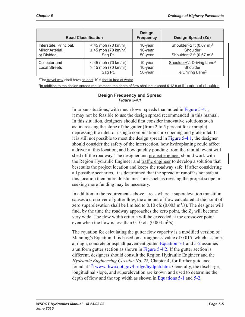
1The travel way shall have at least 10 ft that is free of water.2In addition to the design spread requirement, the depth of flow shall not exceed 0.12 ft at the edge of shoulder.
Design Frequency and SpreadFigure 5-4.1
In urban situations, with much lower speeds than noted in Figure 5-4.1, it may not be feasible to use the design spread recommended in this manual. In this situation, designers should first consider innovative solutions such as: increasing the slope of the gutter (from 2 to 5 percent for example), depressing the inlet, or using a combination curb opening and grate inlet. If it is still not possible to meet the design spread in Figure 5-4.1, the designer should consider the safety of the intersection, how hydroplaning could affect a driver at this location, and how quickly ponding from the rainfall event will shed off the roadway. The designer and project engineer should work with the Region Hydraulic Engineer and traffic engineer to develop a solution that best suits the project location and keeps the roadway safe. If after considering all possible scenarios, it is determined that the spread of runoff is not safe at this location then more drastic measures such as revising the project scope or seeking more funding may be necessary.
In addition to the requirements above, areas where a superelevation transition causes a crossover of gutter flow, the amount of flow calculated at the point of zero superelevation shall be limited to 0.10 cfs (0.003 m3/s). The designer will find, by the time the roadway approaches the zero point, the Zd will become very wide. The flow width criteria will be exceeded at the crossover point even when the flow is less than 0.10 cfs (0.003 m3/s).
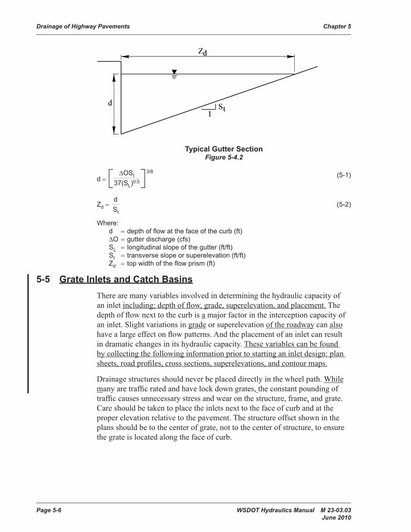
The equation for calculating the gutter flow capacity is a modified version of Manning’s Equation. It is based on a roughness value of 0.015, which assumes a rough, concrete or asphalt pavement gutter. Equation 5-1 and 5-2 assumes a uniform gutter section as shown in Figure 5-4.2. If the gutter section is different, designers should consult the Region Hydraulic Engineer and the Hydraulic Engineering Circular No. 22, Chapter 4, for further guidance found at www.fhwa.dot.gov/bridge/hydpub.htm. Generally, the discharge, longitudinal slope, and superelevation are known and used to determine the depth of flow and the top width as shown in Equations 5-1 and 5-2.
Page 5-6 WSDOT Hydraulics Manual M 23-03.03 June 2010
Drainage of Highway Pavements Chapter 5
Typical Gutter SectionFigure 5-4.2
d = [ ∆OSt 37(SL)0.5]3/8 (5-1)
Zd = d St
(5-2)
Where:d = depth of flow at the face of the curb (ft)∆O = gutter discharge (cfs)SL = longitudinal slope of the gutter (ft/ft)St = transverse slope or superelevation (ft/ft)Zd = top width of the flow prism (ft)
5-5 Grate Inlets and Catch BasinsThere are many variables involved in determining the hydraulic capacity of an inlet including; depth of flow, grade, superelevation, and placement. The depth of flow next to the curb is a major factor in the interception capacity of an inlet. Slight variations in grade or superelevation of the roadway can also have a large effect on flow patterns. And the placement of an inlet can result in dramatic changes in its hydraulic capacity. These variables can be found by collecting the following information prior to starting an inlet design: plan sheets, road profiles, cross sections, superelevations, and contour maps.
Drainage structures should never be placed directly in the wheel path. While many are traffic rated and have lock down grates, the constant pounding of traffic causes unnecessary stress and wear on the structure, frame, and grate. Care should be taken to place the inlets next to the face of curb and at the proper elevation relative to the pavement. The structure offset shown in the plans should be to the center of grate, not to the center of structure, to ensure the grate is located along the face of curb.

WSDOT Hydraulics Manual M 23-03.03 Page 5-7 June 2010
Chapter 5 Drainage of Highway Pavements
Generally, median barrier scuppers are not recommended for passing runoff from one side of the barrier to a drainage structure on the other side. Instead inlets placed on each side of the median barrier should be installed as shown in Standard Plan B-95.20-00, allowing runoff to pass between the structures via a drainpipe.
Debris floating in the gutter has a tendency to collect at the inlets, plugging part or all of the grate opening. Inlets locations on a continuous grade are calculated using the full width of the grate with no allowance needed for debris. Inlets located in a sump are analyzed with an allowance for debris and are further discussed in Section 5-5.4. Areas with deciduous trees and large pedestrian populations are more prone to debris plugging. Bark from logging operations and agricultural areas are also known to cause debris problems.
This section has been divided into three areas: inlets on a continuous grade, side flow interception and sag analysis. Properties of grate inlets available in the WSDOT Standard Plans are summarized in Figure 5-5.7 and further discussed below.
5-5.1 Inlet Types
The characteristics of the most commonly used inlets at WSDOT are summarized below. For inlet additional specifications including dimensions, see Standard Plans, Section B, Drainage Structures and Hydraulics.
Herringbone Pattern or Standard Plan B-30.50
The HQ Hydraulics Office no longer recommends using herringbone grates. Historically, use of the vaned grate was limited due to cost considerations. The cost difference now is minimal, the vaned grate is bicycle safe, and as described further in this section is hydraulically superior under most conditions. Installation of the vaned grate is critical as the grate is directional. If installed backwards the interception capacity is severely limited. Figure 5-5.1 includes the herringbone information for existing conditions only, it is not intended for new construction.
Page 5-8 WSDOT Hydraulics Manual M 23-03.03 June 2010
Drainage of Highway Pavements Chapter 5
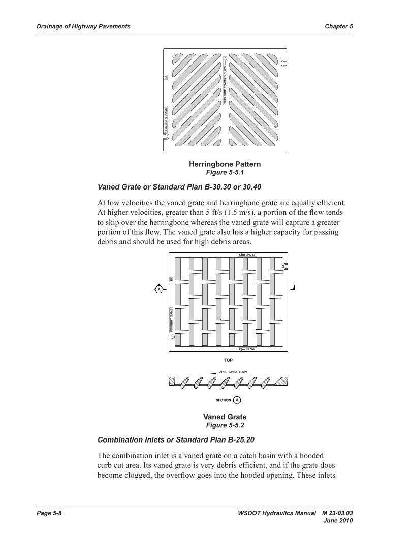
Herringbone PatternFigure 5-5.1
Vaned Grate or Standard Plan B-30.30 or 30.40
At low velocities the vaned grate and herringbone grate are equally efficient. At higher velocities, greater than 5 ft/s (1.5 m/s), a portion of the flow tends to skip over the herringbone whereas the vaned grate will capture a greater portion of this flow. The vaned grate also has a higher capacity for passing debris and should be used for high debris areas.
Vaned GrateFigure 5-5.2
Combination Inlets or Standard Plan B-25.20
The combination inlet is a vaned grate on a catch basin with a hooded curb cut area. Its vaned grate is very debris efficient, and if the grate does become clogged, the overflow goes into the hooded opening. These inlets
WSDOT Hydraulics Manual M 23-03.03 Page 5-9 June 2010
Chapter 5 Drainage of Highway Pavements
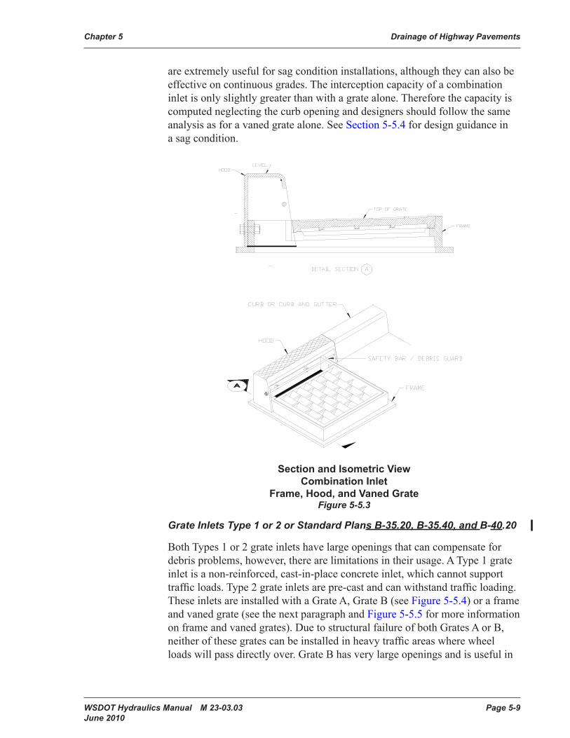
are extremely useful for sag condition installations, although they can also be effective on continuous grades. The interception capacity of a combination inlet is only slightly greater than with a grate alone. Therefore the capacity is computed neglecting the curb opening and designers should follow the same analysis as for a vaned grate alone. See Section 5-5.4 for design guidance in a sag condition.
Section and Isometric View Combination Inlet
Frame, Hood, and Vaned GrateFigure 5-5.3
Grate Inlets Type 1 or 2 or Standard Plans B-35.20, B-35.40, and B-40.20
Both Types 1 or 2 grate inlets have large openings that can compensate for debris problems, however, there are limitations in their usage. A Type 1 grate inlet is a non-reinforced, cast-in-place concrete inlet, which cannot support traffic loads. Type 2 grate inlets are pre-cast and can withstand traffic loading. These inlets are installed with a Grate A, Grate B (see Figure 5-5.4) or a frame and vaned grate (see the next paragraph and Figure 5-5.5 for more information on frame and vaned grates). Due to structural failure of both Grates A or B, neither of these grates can be installed in heavy traffic areas where wheel loads will pass directly over. Grate B has very large openings and is useful in
Page 5-10 WSDOT Hydraulics Manual M 23-03.03 June 2010
Drainage of Highway Pavements Chapter 5
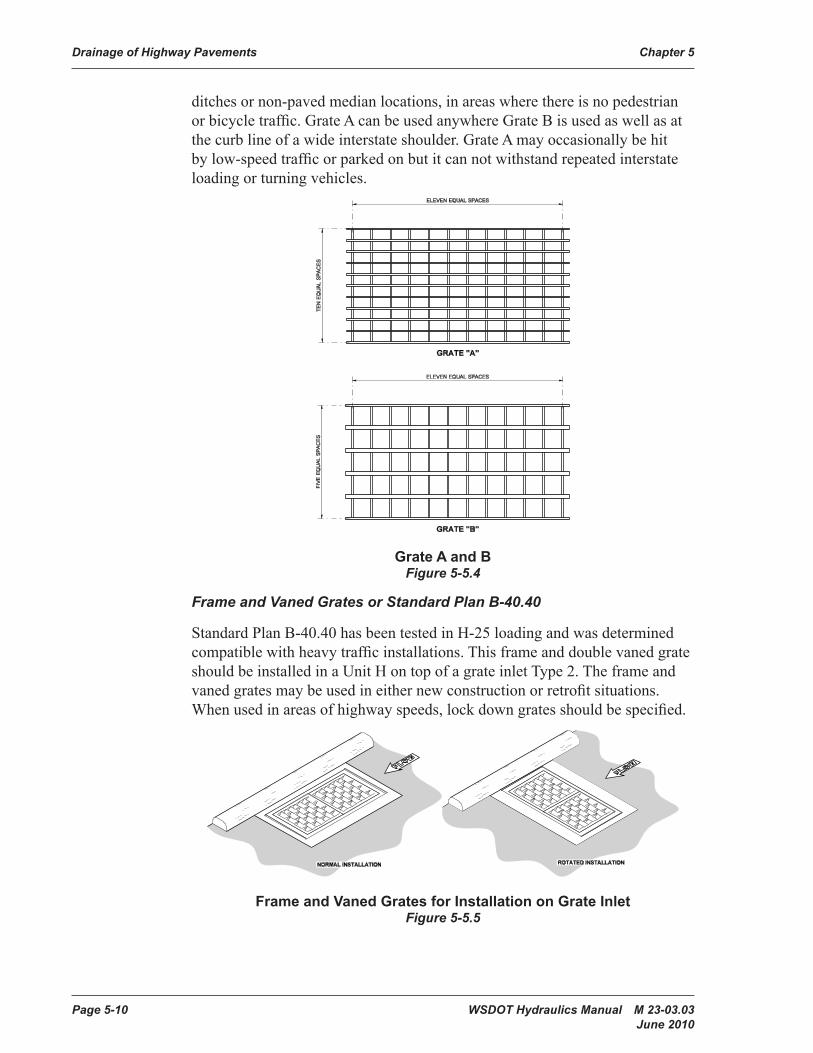
ditches or non-paved median locations, in areas where there is no pedestrian or bicycle traffic. Grate A can be used anywhere Grate B is used as well as at the curb line of a wide interstate shoulder. Grate A may occasionally be hit by low-speed traffic or parked on but it can not withstand repeated interstate loading or turning vehicles.
Grate A and BFigure 5-5.4
Frame and Vaned Grates or Standard Plan B-40.40
Standard Plan B-40.40 has been tested in H-25 loading and was determined compatible with heavy traffic installations. This frame and double vaned grate should be installed in a Unit H on top of a grate inlet Type 2. The frame and vaned grates may be used in either new construction or retrofit situations. When used in areas of highway speeds, lock down grates should be specified.
Frame and Vaned Grates for Installation on Grate InletFigure 5-5.5
WSDOT Hydraulics Manual M 23-03.03 Page 5-11 June 2010
Chapter 5 Drainage of Highway Pavements
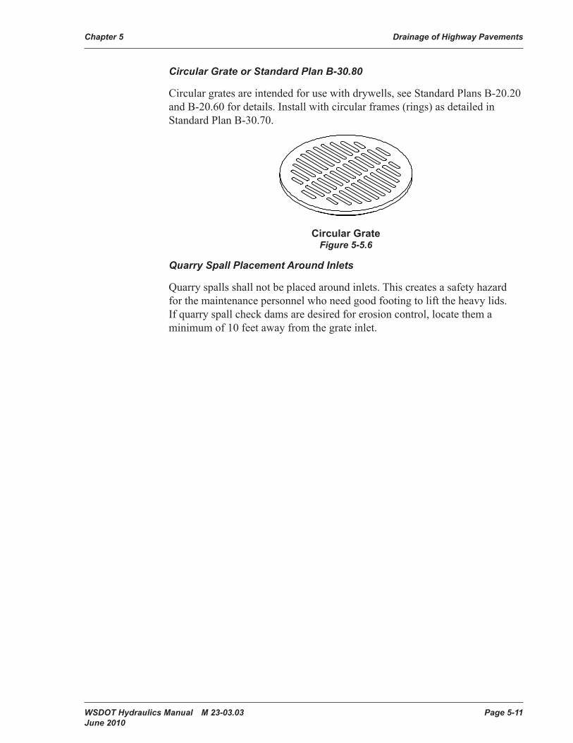
Circular Grate or Standard Plan B-30.80
Circular grates are intended for use with drywells, see Standard Plans B-20.20 and B-20.60 for details. Install with circular frames (rings) as detailed in Standard Plan B-30.70.
Circular GrateFigure 5-5.6
Quarry Spall Placement Around Inlets
Quarry spalls shall not be placed around inlets. This creates a safety hazard for the maintenance personnel who need good footing to lift the heavy lids. If quarry spall check dams are desired for erosion control, locate them a minimum of 10 feet away from the grate inlet.

Page 5-12 WSDOT Hydraulics Manual M 23-03.03 June 2010
Drainage of Highway Pavements Chapter 5
Standard Plan Description
Continuous Grade1Sump Condition2
Perimeter Flows as WeirGrate Width
Grate Length Width Length
B-30.503 Rectangular Herringbone Grate
1.67 ft (0.50 m)
2.0 ft (0.61 m)
0.69 ft (0.21 m)
0.78 ft (0.24 m)
B-30.30 or 30.408
Vaned Grate for Catch Basin and Inlet
1.67 ft (0.50 m
2.0 ft (0.61 m)
1.31 ft (0.40 m)
1.25 ft (0.38 m)
B-25.202 Combination Inlet 1.67 ft (0.50 m
2.0 ft (0.61 m)
1.31 ft (0.40 m)
1.25 ft (0.38 m)
B-40.20 Grate Inlet Type 1(Grate A or B4)
2.01 ft (0.62 m)3.89 ft7(1.20 m)
3.89 ft(0.62 m)2.01 ft7(1.20 m)
1.67 ft(0.50 m) 3.52 ft
(1.07 m)
3.52 ft(1.07 m) 1.67 ft
(0.50 m)B-30.80 Circular Grate9 1.52 ft
(0.47 m)2.55 ft10
(0.79 m)B-40.40 Frame and Vaned Grates
for Grate Inlet Type 21.75 ft5 (0.52 m) 3.52 ft6 (1.05 m)
3.52 ft5(1.05 m)1.75 ft6(0.52 m)
1.29 ft(0.40 m)2.58 ft6(0.80 m)
2.58 ft(0.50 m)1.29 ft6(0.26 m)
1Inlet widths on a continuous grade are not reduced for bar area or for debris accumulation.2The perimeters and areas in this portion of the table have already been reduced for bar area. These values should be cut in half when used in a sag location as described in Section 5-5.4, except for the Combination Inlet B-25.20.3Shown for informational purposes only. See Section 5-5.1.4Type B grate shall not to be used in areas of pedestrian or vehicular traffic. See Section 5-5.1 for further discussion.5Normal Installation, see Figure 5-5.5 or Standard Plans.6Rotated Installation see Figure 5-5.5 or Standard Plans. 7Rotated installation, see Figure 5-5.5 or Standard Plans.8For sag conditions, combinations inlets should use a Bi-Directional Vaned grate as shown in Standard Plan B-30.40.9Circular Grates are only intended for use with dry wells.10Only the perimeter value has been provided for use with weir equations.
Properties of Grate InletsFigure 5-5.7
5-5.2 Capacity of Inlets on a Continuous Grade
The interception capacity of an inlet on a continuous grade depends on the amount of water flowing over the grate, the size and configuration of the grate, the velocity of the flow in the gutter, and the longitudinal slope of the roadway. For longitudinal slopes between 2 to 3 percent and for velocities in the range of 3 to 5 ft/s the interception capacity of an inlet is based mainly on frontal flow. Frontal flow is water that travels through the gutter and enters through the front side (width) of the inlet. For longitudinal slopes less than 2 percent and velocities less than 3 ft/s side flow interception should also be considered as described in Section 5-5.3. An inlet will intercept essentially all frontal flow passing over the width of the inlet as long as the
WSDOT Hydraulics Manual M 23-03.03 Page 5-13 June 2010
Chapter 5 Drainage of Highway Pavements
velocity is less than 5 ft/s. When velocities exceed 5 ft/s water will “splash-over” the inlets reducing the portion of the flow that will be intercepted and increase the bypass flow. The Region Hydraulics Engineer or HQ Hydraulics Office is available to provide direction when velocities exceed 5 ft/s and additional guidance can be found in the FHWA HEC No. 22, Section 4-3 at https://www.fhwa.dot.gov/engineering/hydraulics/library_arc.cfm?pub_number=22&id=140.
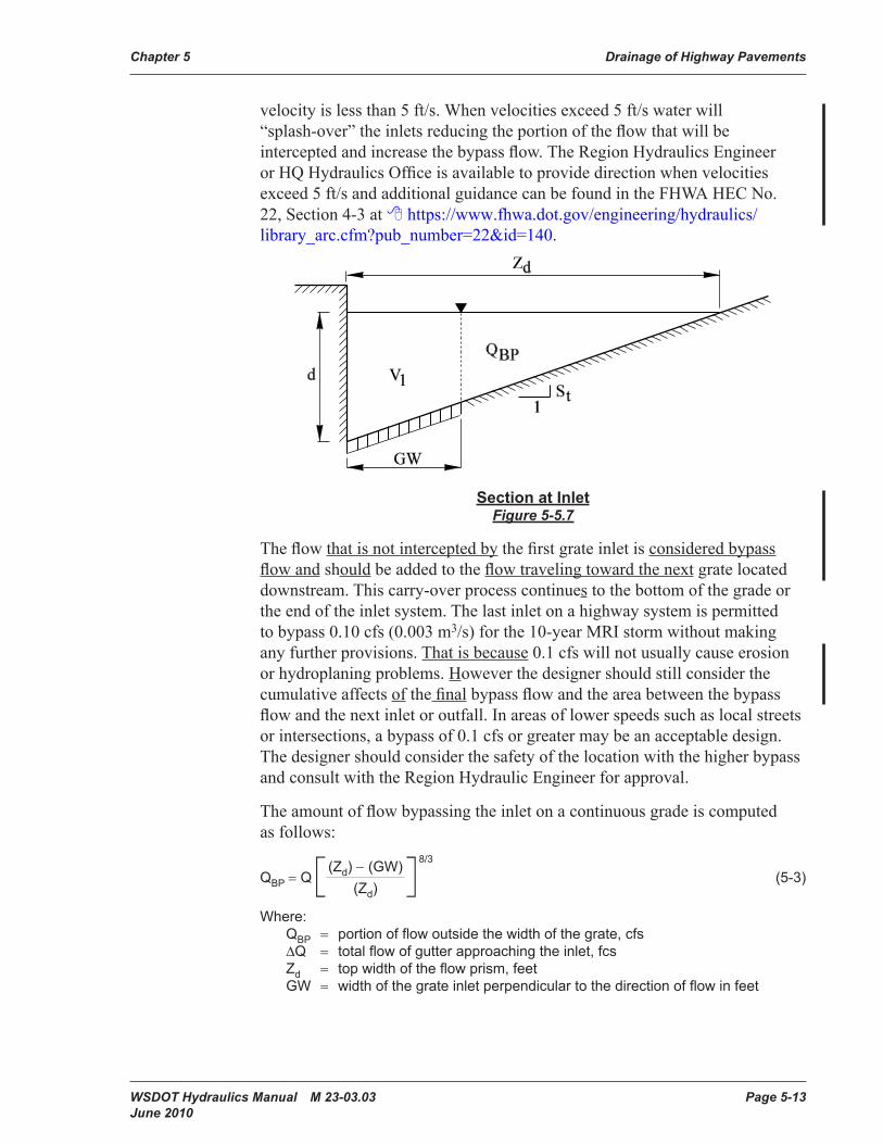
Section at InletFigure 5-5.7
The flow that is not intercepted by the first grate inlet is considered bypass flow and should be added to the flow traveling toward the next grate located downstream. This carry-over process continues to the bottom of the grade or the end of the inlet system. The last inlet on a highway system is permitted to bypass 0.10 cfs (0.003 m3/s) for the 10-year MRI storm without making any further provisions. That is because 0.1 cfs will not usually cause erosion or hydroplaning problems. However the designer should still consider the cumulative affects of the final bypass flow and the area between the bypass flow and the next inlet or outfall. In areas of lower speeds such as local streets or intersections, a bypass of 0.1 cfs or greater may be an acceptable design. The designer should consider the safety of the location with the higher bypass and consult with the Region Hydraulic Engineer for approval.
The amount of flow bypassing the inlet on a continuous grade is computed as follows:
QBP = Q[ (Zd) − (GW)(Zd)
]8/3
(5-3)
Where:QBP = portion of flow outside the width of the grate, cfs∆Q = total flow of gutter approaching the inlet, fcsZd = top width of the flow prism, feetGW = width of the grate inlet perpendicular to the direction of flow in feet
Page 5-14 WSDOT Hydraulics Manual M 23-03.03 June 2010
Drainage of Highway Pavements Chapter 5
The flow that is intercepted by the inlet is calculated as follows.
Qi = ∆Q − QBP (5-4)
The velocity of flow directly over the inlet is calculated as shown in Equation 5-5.
Vcontinuous =Q − QBP
(GW)[d − 0.5(GW)(St)](5-5)
Where:Vcontinuous = velocity over the inlet in ft/s (m/s)St = transverse slope or superelevation in ft/ft (m/m)d = depth of flow at the face of the curb ft (m)
5-5.3 Side Flow Interception
For longitudinal slopes less than 2 percent and when Equation 5-5 yields velocities less than 3 ft/s, side flow interception begins to make an appreciable contribution to the inlet capacity analysis and should be considered.
The velocity of flow entering the side of an inlet is shown in Equation 5-6 below.
Vside = ( 1.11 n ) (SL
0.5St0.67Zd
0.67) (5-6)
Where:Vside = velocity in triangular channel, ft/sn = 0.015 (Manning’s value for concrete pavement)SL = longitudinal slope
The ratio of frontal flow to total gutter flow is shown in Equation 5-7 below.
EO = 1 − (1 −GW Zd )
2.67
(5-7)
Where:GW = width of depressed grate, ftZd = top width of the flow prism, ft

WSDOT Hydraulics Manual M 23-03.03 Page 5-15 June 2010
Chapter 5 Drainage of Highway Pavements
The ratio of side flow intercepted to total side flow is shown in Equation 5-8 below.
Rs = 1 (5-8)
(1 +0.15Vside
1.8 StGL2.3 )
The efficiency of the grate is expressed in Equation 5-9 below.
E = RfEo + Rs(1 − Eo) (5-9)
The amount of flow intercepted by an inlet when side flow is considered is expressed in Equation 5-10 below:
Qi = Q(RfEo + Rs(1 − Eo)) (5-10)
5-5.3.1 Inlet Analysis Spreadsheet
When locating and determining the capacity of inlets on a continuous grade, the process described in Sections 5-5.2 and 5-5.3 and illustrated in this example should be followed. A Microsoft Excel spreadsheet has been developed that follows this procedure to calculate roadway runoff and inlet interception for a roadway on a longitudinal slope. When velocities are less than 3 ft/s and the longitudinal slope is less than 2 percent, the spreadsheet will automatically consider side flow in the analysis. Also, when velocities exceed 5 ft/s or the bypass flow at the last inlet exceeds 0.1 cfs, the spreadsheet will warn the designer. The spreadsheet is located at www.wsdot.wa.gov/Design/Hydraulics/Programdownloads.htm.
5-5.3.2 Example
The project is located in Seattle on a non-interstate roadway with a posted speed limit of 35 mph. The high point of a vertical curve is at Station 41+00. The width of pavement is 38 ft (11.5 m), with a 5 ft shoulder and three 11 ft lanes. A proposed drainage system consists of grate inlets placed at the following stations:
Station (SL) Longitudinal Grade (St) Superelevation
48+50 0.011 0.035
51+50 0.011 0.022
54+50 0.011 0.02
57+50 0.011 0.02
59+00 0.011 0.02
Page 5-16 WSDOT Hydraulics Manual M 23-03.03 June 2010
Drainage of Highway Pavements Chapter 5
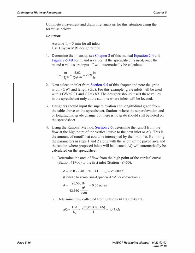
Complete a pavement and drain inlet analysis for this situation using the formulas below:
Solution:
Assume Tc = 5 min for all inlets Use 10-year MRI design rainfall
1. Determine the intensity, see Chapter 2 of this manual Equation 2-4 and Figure 2-5.4B for m and n values. If the spreadsheet is used, once the m and n values are input ‘I’ will automatically be calculated.
I = m
(Tc)n=
5.62 (5)0.530 = 2.39
in hr
2. Next select an inlet from Section 5-5 of this chapter and note the grate width (GW) and length (GL). For this example, grate inlets will be used with a GW=2.01 and GL=3.89. The designer should insert these values in the spreadsheet only at the stations where inlets will be located.
3. Designers should input the superelevation and longitudinal grade from the table above on the spreadsheet. Stations where the superelevation and or longitudinal grade change but there is no grate should still be noted on the spreadsheet.
4. Using the Rational Method, Section 2-5, determine the runoff from the flow at the high point of the vertical curve to the next inlet or ∆Q. This is the amount of runoff that could be intercepted by the first inlet. By noting the parameters in steps 1 and 2 along with the width of the paved area and the station where proposed inlets will be located, ∆Q will automatically be calculated on the spreadsheet.
a. Determine the area of flow from the high point of the vertical curve (Station 41+00) to the first inlet (Station 48+50).
A = 38 ft × ((48 + 50 − 41 + 00)) = 28,500 ft2
(Convert to acres; see Appendix A 1-1 for conversion.)
A = 28,500 ft2
43,560 ft2 acre
= 0.65 acres
b. Determine flow collected from Stations 41+00 to 48+50.
∆Q = CIA Kc
=(0.9)(2.39)(0.65)
1= 1.41 cfs
WSDOT Hydraulics Manual M 23-03.03 Page 5-17 June 2010
Chapter 5 Drainage of Highway Pavements
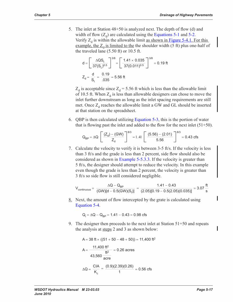
5. The inlet at Station 48+50 is analyzed next. The depth of flow (d) and width of flow (Zd) are calculated using the Equations 5-1 and 5-2. Verify Zd is within the allowable limit as shown in Figure 5-4.1. For this example, the Zd is limited to the the shoulder width (5 ft) plus one-half of the traveled lane (5.50 ft) or 10.5 ft.
d =[ ∆QSt 37(SL)0.5 ]
3/8
=[ 1.41 × 0.035 37(0.011)0.5 ]
3/8
= 0.19 ft
Zd = d St
=0.19 .035
= 5.56 ft
Zd is acceptable since Zd = 5.56 ft which is less than the allowable limit of 10.5 ft. When Zd is less than allowable designers can chose to move the inlet further downstream as long as the inlet spacing requirements are still met. Once Zd reaches the allowable limit a GW and GL should be inserted at that station on the spreadsheet.
6. QBP is then calculated utilizing Equation 5-3, this is the portion of water that is flowing past the inlet and added to the flow for the next inlet (51+50).
QBP = ∆Q [ (Zd) − (GW) Zd
]8/3
= 1.41[ (5.56) − (2.01) 5.56 ]8/3
= 0.43 cfs
7. Calculate the velocity to verify it is between 3-5 ft/s. If the velocity is less than 3 ft/s and the grade is less than 2 percent, side flow should also be considered as shown in Example 5-5.3.3. If the velocity is greater than 5 ft/s, the designer should attempt to reduce the velocity. In this example even though the grade is less than 2 percent, the velocity is greater than 3 ft/s so side flow is still considered negligible.
Vcontinuous =∆Q − QBP
(GW)[d − 0.5(GW)(St)]=
1.41 − 0.43 (2.05)[0.19 − 0.5(2.05)(0.035)]
= 3.07ft s
8. Next, the amount of flow intercepted by the grate is calculated using Equation 5-4.
Qi = ∆Q − QBP = 1.41 − 0.43 = 0.98 cfs
9. The designer then proceeds to the next inlet at Station 51+50 and repeats the analysis at steps 2 and 3 as shown below:
A = 38 ft × ((51 + 50 − 48 + 50)) = 11,400 ft2
A = 11,400 ft2
43,560 ft2 acre
= 0.26 acres
∆Q =CIA Kc
= (0.9)(2.39)(0.26) 1
= 0.56 cfs
Page 5-18 WSDOT Hydraulics Manual M 23-03.03 June 2010
Drainage of Highway Pavements Chapter 5
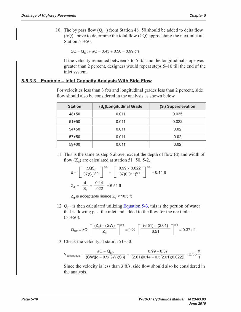
10. The by pass flow (QBP) from Station 48+50 should be added to delta flow (∆Q) above to determine the total flow (ΣQ) approaching the next inlet at Station 51+50.
ΣQ = QBP + ∆Q = 0.43 + 0.56 = 0.99 cfs
If the velocity remained between 3 to 5 ft/s and the longitudinal slope was greater than 2 percent, designers would repeat steps 5–10 till the end of the inlet system.
5-5.3.3 Example – Inlet Capacity Analysis With Side Flow
For velocities less than 3 ft/s and longitudinal grades less than 2 percent, side flow should also be considered in the analysis as shown below.
Station (SL)Longitudinal Grade (St) Superelevation
48+50 0.011 0.035
51+50 0.011 0.022
54+50 0.011 0.02
57+50 0.011 0.02
59+00 0.011 0.02
11. This is the same as step 5 above; except the depth of flow (d) and width of flow (Zd) are calculated at station 51+50. 5-2.
d = [ ∆QSt 37(SL)0.5 ]3/8
= [ 0.99 × 0.022 37(0.011)0.5 ]3/8
= 0.14 ft
Zd = d St
=0.14 .022
= 6.51 ft
Zd is acceptable sisnce Zd < 10.5 ft
12. QBP is then calculated utilizing Equation 5-3, this is the portion of water that is flowing past the inlet and added to the flow for the next inlet (51+50).
QBP = ∆Q [ (Zd) − (GW) Zd
]8/3
= 0.99 [ (6.51) − (2.01) 6.51 ]8/3
= 0.37 cfs
13. Check the velocity at station 51+50.
Vcontinuous =∆Q − QBP
(GW)[d − 0.5(GW)(St)]=
0.99 − 0.37 (2.01)[0.14 − 0.5(2.01)(0.022)]
= 2.55ft s
Since the velocity is less than 3 ft/s, side flow should also be considered in the analysis.
WSDOT Hydraulics Manual M 23-03.03 Page 5-19 June 2010
Chapter 5 Drainage of Highway Pavements
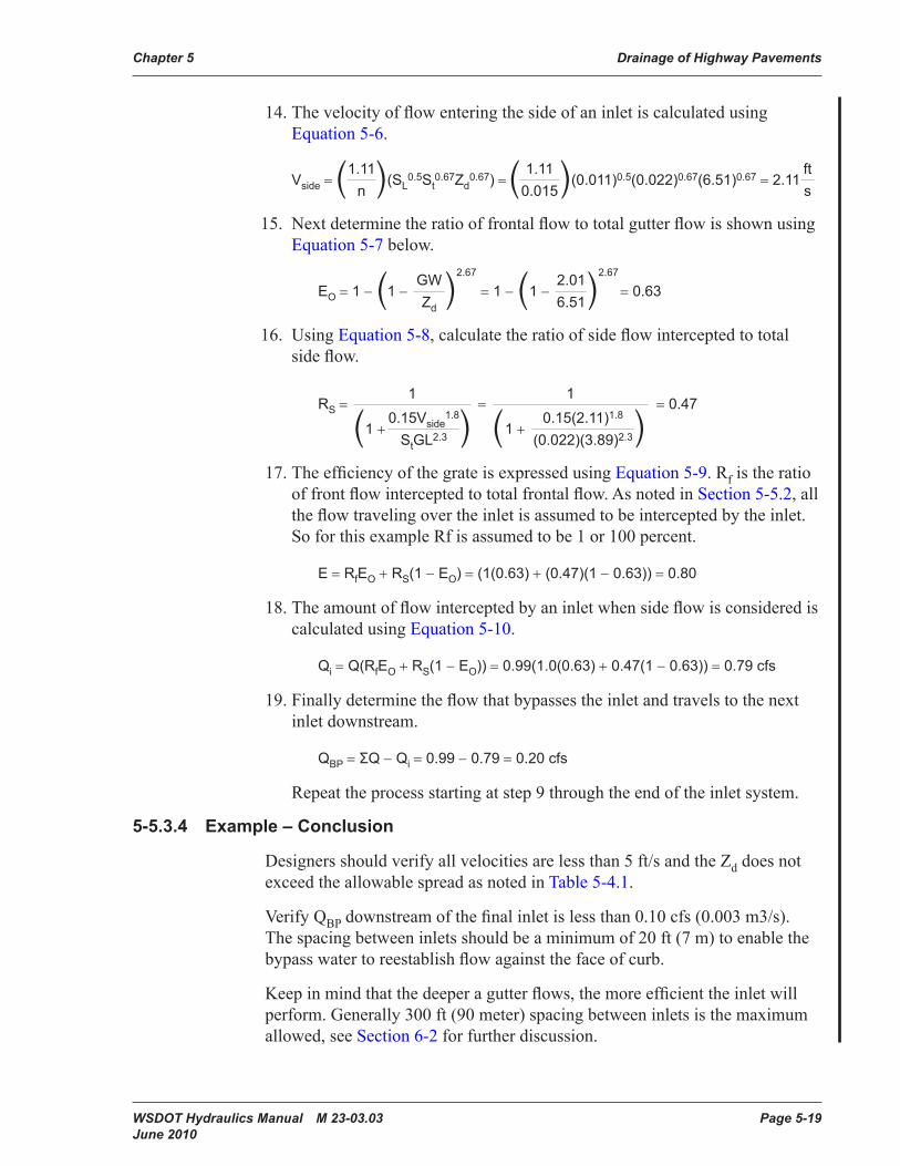
14. The velocity of flow entering the side of an inlet is calculated using Equation 5-6.
Vside = (1.11 n )(SL
0.5St0.67Zd
0.67) = ( 1.11 0.015)(0.011)0.5(0.022)0.67(6.51)0.67 = 2.11
ft s
15. Next determine the ratio of frontal flow to total gutter flow is shown using Equation 5-7 below.
EO = 1 − (1 −GW Zd )
2.67
= 1 − (1 −2.01 6.51)2.67
= 0.63
16. Using Equation 5-8, calculate the ratio of side flow intercepted to total side flow.
RS = 1
=1
= 0.47
(1 +0.15Vside
1.8 StGL2.3 ) (1 +
0.15(2.11)1.8 (0.022)(3.89)2.3)
17. The efficiency of the grate is expressed using Equation 5-9. Rf is the ratio of front flow intercepted to total frontal flow. As noted in Section 5-5.2, all the flow traveling over the inlet is assumed to be intercepted by the inlet. So for this example Rf is assumed to be 1 or 100 percent.
E = RfEO + RS(1 − EO) = (1(0.63) + (0.47)(1 − 0.63)) = 0.80
18. The amount of flow intercepted by an inlet when side flow is considered is calculated using Equation 5-10.
Qi = Q(RfEO + RS(1 − EO)) = 0.99(1.0(0.63) + 0.47(1 − 0.63)) = 0.79 cfs
19. Finally determine the flow that bypasses the inlet and travels to the next inlet downstream.
QBP = ΣQ − Qi = 0.99 − 0.79 = 0.20 cfs
Repeat the process starting at step 9 through the end of the inlet system.
5-5.3.4 Example – Conclusion
Designers should verify all velocities are less than 5 ft/s and the Zd does not exceed the allowable spread as noted in Table 5-4.1.
Verify QBP downstream of the final inlet is less than 0.10 cfs (0.003 m3/s). The spacing between inlets should be a minimum of 20 ft (7 m) to enable the bypass water to reestablish flow against the face of curb.
Keep in mind that the deeper a gutter flows, the more efficient the inlet will perform. Generally 300 ft (90 meter) spacing between inlets is the maximum allowed, see Section 6-2 for further discussion.
Page 5-20 WSDOT Hydraulics Manual M 23-03.03 June 2010
Drainage of Highway Pavements Chapter 5
5-5.4 Capacity of Inlets in Sag Locations
By definition, a sag is any portion of the roadway where the profile changes from a negative grade to a positive grade. Inlets at sag locations perform differently than inlets on a continuous grade and therefore require a different design criterion. Theoretically, inlets at sag locations may operate in one of two ways: (1) at low ponding depths, the inlet will operate as a weir; (2) high ponding depths (5″ depth above the grated inlet and 1.4 times the grate opening height for combination inlets), the inlet will operate as an orifice. It is very rare that ponding on a roadway will become deep enough to force the inlet to operate as an orifice. As a result, this section will focus on inlets operating as a weir with flow spilling in from the three sides of the inlet that are exposed to the ponding.
Inlets at sag locations can easily become plugged with debris and therefore, it is good engineering practice to provide some type of relief. This relief can be accomplished by locating flanking inlets, on either side of the sag inlet, so they will operate before water exceeds the allowable spread into the travel lane at the sag. This manual recommends flanking inlets be located so the depth of water at the flanking inlet ponds to half the allowable depth at the sag (or ½dB). With that said, flanking inlets are only required when the sag is located in a depressed area and water has no outlet except through the system. A curb, traffic barrier, retaining wall, or other obstruction, which prevents the runoff from flowing off of the traveled roadway, generally contains this ponded area. However, if runoff is capable of overtopping the curb and flowing away from the roadway before exceeding the allowable limits noted in Figure 5-4.1, flanking inlets are not required. With this situation there is a low potential for danger to the drivers of the roadway if the inlets do not function as designed. Before flanking inlets are removed in this situation, designers should consider the potential damage of water going over the curb. Designers should use the guidelines provided in this section for locating flanking inlets. If a designer suspects flanking inlets are unnecessary, consult the Region Hydraulics Engineer early in the design for approval.
Any section of roadway located in a sag should be designed according to the criteria described below. To aid the designer in sag analysis, a copy of the sag worksheet is located on the HQ Hydraulic web page at http://www.wsdot.wa.gov/publications/fulltext/Hydraulics/Programs/SagWorksheetud.xls.
WSDOT Hydraulics Manual M 23-03.03 Page 5-21 June 2010
Chapter 5 Drainage of Highway Pavements
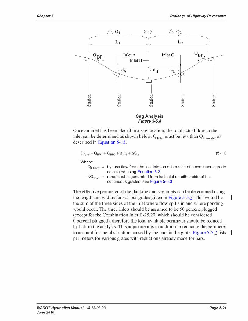
Sag AnalysisFigure 5-5.8
Once an inlet has been placed in a sag location, the total actual flow to the inlet can be determined as shown below. QTotal must be less than Qallowable as described in Equation 5-13.
QTotal = QBP1 + QBP2 + ∆Q1 + ∆Q2 (5-11)
Where:QBP1&2 = bypass flow from the last inlet on either side of a continuous grade
calculated using Equation 5-3∆Q1&2 = runoff that is generated from last inlet on either side of the
continuous grades, see Figure 5-5.3
The effective perimeter of the flanking and sag inlets can be determined using the length and widths for various grates given in Figure 5-5.7. This would be the sum of the three sides of the inlet where flow spills in and where ponding would occur. The three inlets should be assumed to be 50 percent plugged (except for the Combination Inlet B-25.20, which should be considered 0 percent plugged), therefore the total available perimeter should be reduced by half in the analysis. This adjustment is in addition to reducing the perimeter to account for the obstruction caused by the bars in the grate. Figure 5-5.7 lists perimeters for various grates with reductions already made for bars.
Page 5-22 WSDOT Hydraulics Manual M 23-03.03 June 2010
Drainage of Highway Pavements Chapter 5
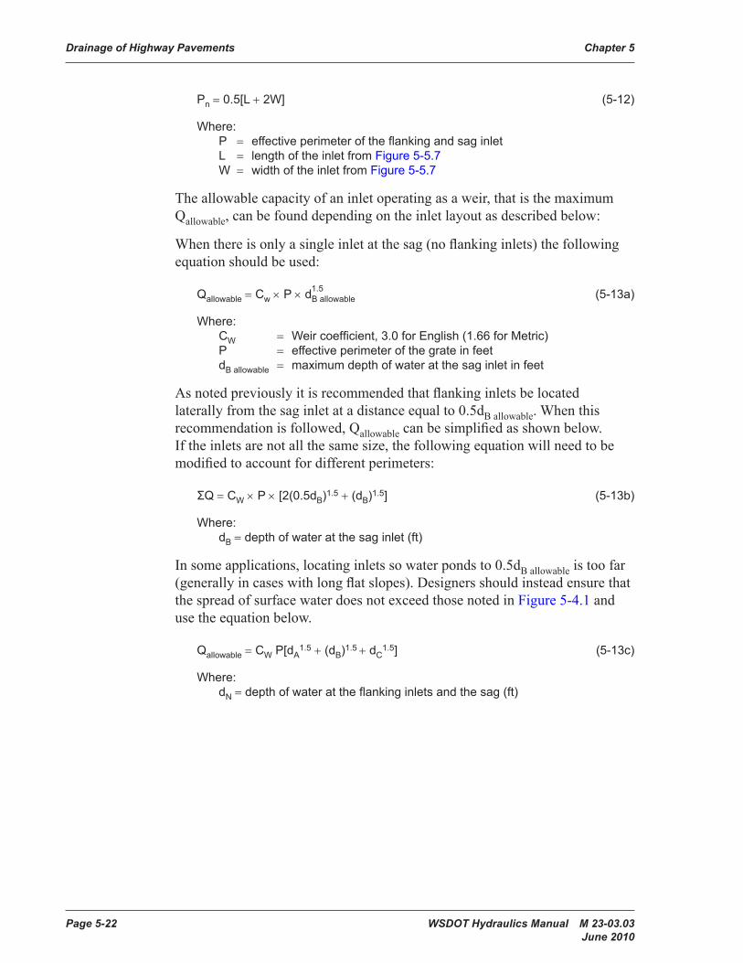
Pn = 0.5[L + 2W] (5-12)
Where:P = effective perimeter of the flanking and sag inletL = length of the inlet from Figure 5-5.7W = width of the inlet from Figure 5-5.7
The allowable capacity of an inlet operating as a weir, that is the maximum Qallowable, can be found depending on the inlet layout as described below:
When there is only a single inlet at the sag (no flanking inlets) the following equation should be used:
Qallowable = Cw × P × dB allowable (5-13a)
Where:CW = Weir coefficient, 3.0 for English (1.66 for Metric)P = effective perimeter of the grate in feetdB allowable = maximum depth of water at the sag inlet in feet
As noted previously it is recommended that flanking inlets be located laterally from the sag inlet at a distance equal to 0.5dB allowable. When this recommendation is followed, Qallowable can be simplified as shown below. If the inlets are not all the same size, the following equation will need to be modified to account for different perimeters:
ΣQ = CW × P × [2(0.5dB)1.5 + (dB)1.5] (5-13b)
Where:dB = depth of water at the sag inlet (ft)
In some applications, locating inlets so water ponds to 0.5dB allowable is too far (generally in cases with long flat slopes). Designers should instead ensure that the spread of surface water does not exceed those noted in Figure 5-4.1 and use the equation below.
Qallowable = CW P[dA1.5 + (dB)1.5 + dC
1.5] (5-13c)
Where:dN = depth of water at the flanking inlets and the sag (ft)
1.5
WSDOT Hydraulics Manual M 23-03.03 Page 5-23 June 2010
Chapter 5 Drainage of Highway Pavements
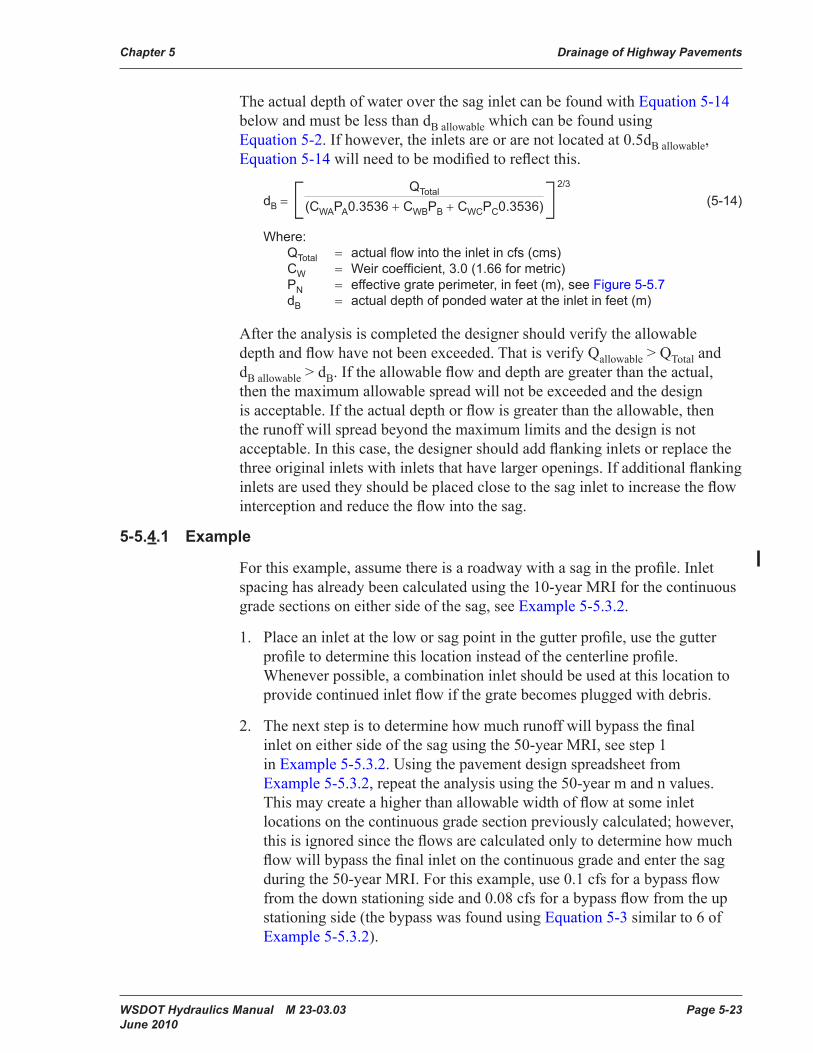
The actual depth of water over the sag inlet can be found with Equation 5-14 below and must be less than dB allowable which can be found using Equation 5-2. If however, the inlets are or are not located at 0.5dB allowable, Equation 5-14 will need to be modified to reflect this.
dB = [ QTotal (CWAPA0.3536 + CWBPB + CWCPC0.3536)]
2/3
(5-14)
Where:QTotal = actual flow into the inlet in cfs (cms)CW = Weir coefficient, 3.0 (1.66 for metric)PN = effective grate perimeter, in feet (m), see Figure 5-5.7dB = actual depth of ponded water at the inlet in feet (m)
After the analysis is completed the designer should verify the allowable depth and flow have not been exceeded. That is verify Qallowable > QTotal and dB allowable > dB. If the allowable flow and depth are greater than the actual, then the maximum allowable spread will not be exceeded and the design is acceptable. If the actual depth or flow is greater than the allowable, then the runoff will spread beyond the maximum limits and the design is not acceptable. In this case, the designer should add flanking inlets or replace the three original inlets with inlets that have larger openings. If additional flanking inlets are used they should be placed close to the sag inlet to increase the flow interception and reduce the flow into the sag.
5-5.4.1 Example
For this example, assume there is a roadway with a sag in the profile. Inlet spacing has already been calculated using the 10-year MRI for the continuous grade sections on either side of the sag, see Example 5-5.3.2.
1. Place an inlet at the low or sag point in the gutter profile, use the gutter profile to determine this location instead of the centerline profile. Whenever possible, a combination inlet should be used at this location to provide continued inlet flow if the grate becomes plugged with debris.
2. The next step is to determine how much runoff will bypass the final inlet on either side of the sag using the 50-year MRI, see step 1 in Example 5-5.3.2. Using the pavement design spreadsheet from Example 5-5.3.2, repeat the analysis using the 50-year m and n values. This may create a higher than allowable width of flow at some inlet locations on the continuous grade section previously calculated; however, this is ignored since the flows are calculated only to determine how much flow will bypass the final inlet on the continuous grade and enter the sag during the 50-year MRI. For this example, use 0.1 cfs for a bypass flow from the down stationing side and 0.08 cfs for a bypass flow from the up stationing side (the bypass was found using Equation 5-3 similar to 6 of Example 5-5.3.2).
Page 5-24 WSDOT Hydraulics Manual M 23-03.03 June 2010
Drainage of Highway Pavements Chapter 5
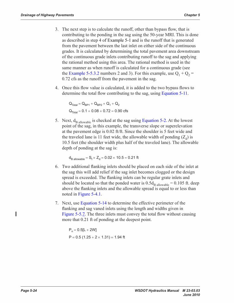
3. The next step is to calculate the runoff, other than bypass flow, that is contributing to the ponding in the sag using the 50-year MRI. This is done as described in step 4 of Example 5-1 and is the runoff that is generated from the pavement between the last inlet on either side of the continuous grades. It is calculated by determining the total pavement area downstream of the continuous grade inlets contributing runoff to the sag and applying the rational method using this area. The rational method is used in the same manner as when runoff is calculated for a continuous grade (see the Example 5-5.3.2 numbers 2 and 3). For this example, use Q1 + Q2 = 0.72 cfs as the runoff from the pavement in the sag.
4. Once this flow value is calculated, it is added to the two bypass flows to determine the total flow contributing to the sag, using Equation 5-11.
QTotal = QBP1 + QBP2 + Q1 + Q2
QTotal = 0.1 + 0.08 + 0.72 = 0.90 cfs
5. Next, dB allowable is checked at the sag using Equation 5-2. At the lowest point of the sag, in this example, the transverse slope or superelevation at the pavement edge is 0.02 ft/ft. Since the shoulder is 5 feet wide and the traveled lane is 11 feet wide, the allowable width of ponding (Zd) is 10.5 feet (the shoulder width plus half of the traveled lane). The allowable depth of ponding at the sag is:
dB allowable = St × Zd = 0.02 × 10.5 = 0.21 ft
6. Two additional flanking inlets should be placed on each side of the inlet at the sag this will add relief if the sag inlet becomes clogged or the design spread is exceeded. The flanking inlets can be regular grate inlets and should be located so that the ponded water is 0.5dB allowable = 0.105 ft. deep above the flanking inlets and the allowable spread is equal to or less than noted in Figure 5-4.1.
7. Next, use Equation 5-14 to determine the effective perimeter of the flanking and sag vaned inlets using the length and widths given in Figure 5-5.7. The three inlets must convey the total flow without causing more that 0.21 ft of ponding at the deepest point.
Pn = 0.5[L + 2W]
P = 0.5 (1.25 + 2 × 1.31) = 1.94 ft
WSDOT Hydraulics Manual M 23-03.03 Page 5-25 June 2010
Chapter 5 Drainage of Highway Pavements
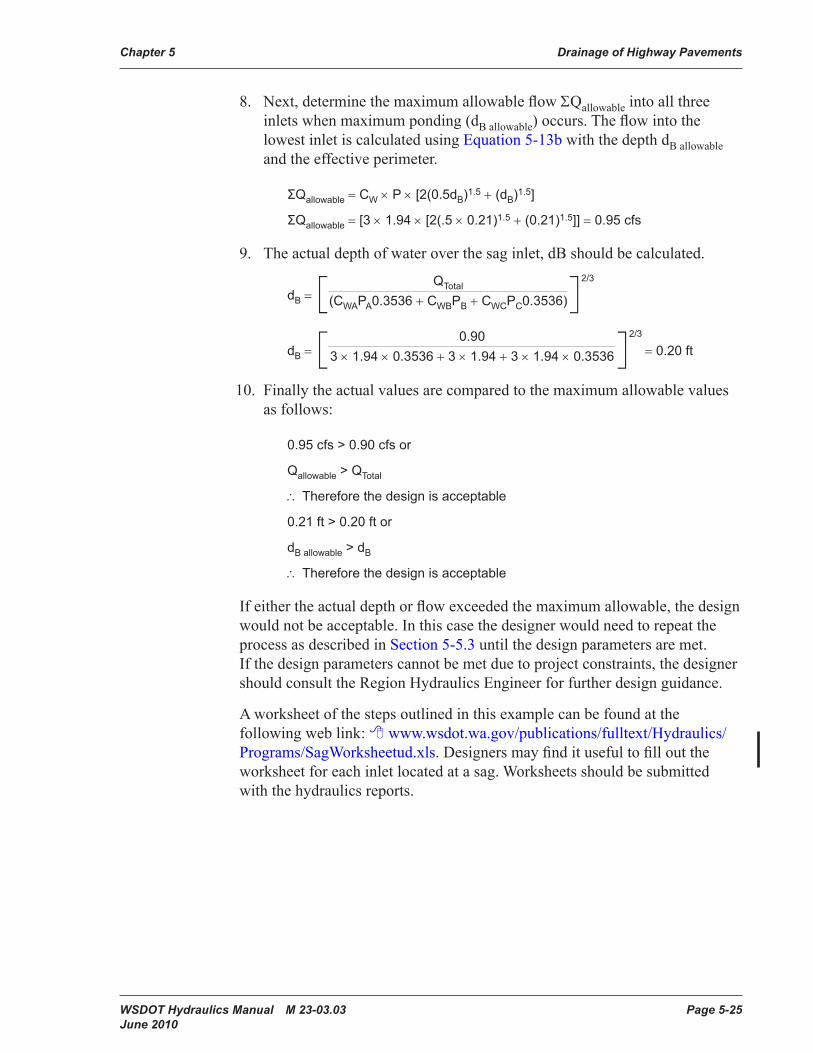
8. Next, determine the maximum allowable flow ΣQallowable into all three inlets when maximum ponding (dB allowable) occurs. The flow into the lowest inlet is calculated using Equation 5-13b with the depth dB allowable and the effective perimeter.
ΣQallowable = CW × P × [2(0.5dB)1.5 + (dB)1.5]
ΣQallowable = [3 × 1.94 × [2(.5 × 0.21)1.5 + (0.21)1.5]] = 0.95 cfs
9. The actual depth of water over the sag inlet, dB should be calculated.
dB = [ QTotal (CWAPA0.3536 + CWBPB + CWCPC0.3536)]
2/3
dB = [ 0.90 3 × 1.94 × 0.3536 + 3 × 1.94 + 3 × 1.94 × 0.3536]
2/3
= 0.20 ft
10. Finally the actual values are compared to the maximum allowable values as follows:
0.95 cfs > 0.90 cfs or
Qallowable > QTotal
∴ Therefore the design is acceptable
0.21 ft > 0.20 ft or
dB allowable > dB
∴ Therefore the design is acceptable
If either the actual depth or flow exceeded the maximum allowable, the design would not be acceptable. In this case the designer would need to repeat the process as described in Section 5-5.3 until the design parameters are met. If the design parameters cannot be met due to project constraints, the designer should consult the Region Hydraulics Engineer for further design guidance.
A worksheet of the steps outlined in this example can be found at the following web link: www.wsdot.wa.gov/publications/fulltext/Hydraulics/Programs/SagWorksheetud.xls. Designers may find it useful to fill out the worksheet for each inlet located at a sag. Worksheets should be submitted with the hydraulics reports.
Page 5-26 WSDOT Hydraulics Manual M 23-03.03 June 2010
Drainage of Highway Pavements Chapter 5
5-6 Hydroplaning and Hydrodynamic DragAs the depth of water flowing over a roadway surfaces increases, the potential for both hydroplaning and hydrodynamic drag increases. Both are discussed in more detail in the subsequent paragraphs below.
Hydrodynamic drag is a term used to describe the force applied to the tire of a vehicle pushing through water as opposed to the tire lifting off the pavement (hydroplaning). The differential force between the tire in the water and the tire out of the water causes the vehicle to “pull” or veer to the side of the water. This usually occurs at speeds less than 50 mph and in water deeper than the depth of the vehicles tire tread. Minimizing water flow depth across lanes and intrusion of flow into lanes will decrease the possibility of hydrodynamic drag.
When rolling tires encounter a film of water on the roadway, the water is channeled through the tire pattern and through the surface roughness of the pavement. Hydroplaning occurs when the drainage capacity of the tire tread pattern and the pavement surface is exceeded and the water begins to build up in front of the tire. As the water builds up, a water wedge is created and this wedge produces a force, which can lift the tire off the pavement surface. This is considered as full dynamic hydroplaning and, since water offers little shear resistance, the tire loses its tractive ability and the driver may lose control of the vehicle.
Hydroplaning is a function of the water depth, roadway geometrics, vehicle speed, tread depth, tire inflation pressure, and conditions of the pavement surface. The following can reduce the hydroplaning potential of a roadway surface:
1. Design the highway geometries to reduce the drainage path lengths of the water flowing over the pavement. This will prevent flow build-up.
2. Increase the pavement surface texture depth by such methods as grooving of Portland cement concrete. An increase of pavement surface texture will increase the drainage capacity at the tire pavement interface.
3. The use of open graded asphaltic pavements has been shown to greatly reduce the hydroplaning potential of the roadway surface. This reduction is due to the ability of the water to be forced through the pavement under the tire. This releases any hydrodynamic pressures that are created and reduces the potential for the tires to hydroplane.
4. The use of drainage structures along the roadway to capture the flow of water over the pavement will reduce the thickness of the film of water and reduce the hydroplaning potential of the roadway surface.