chapter 3 storm drainage system 22 february...
TRANSCRIPT

CHAPTER 3
STORM DRAINAGE SYSTEM
22 February 2000

Drainage Criteria Manual
Chapter Three - Storm Drainage System
Table Of Contents3.1 Overview . . . . . . . . . . . . . . . . . . . . . . . . . . . . . . . . . . . . . . . . . . . . . . . . . . . . . . . . . . . . . . . . . . . . . . . . . . . . . . . 3 - 1
3.1.1 Introduction . . . . . . . . . . . . . . . . . . . . . . . . . . . . . . . . . . . . . . . . . . . . . . . . . . . . . . . . . . . . . . . . . . . . . . . . . 3 - 13.1.2 Symbols and Definitions . . . . . . . . . . . . . . . . . . . . . . . . . . . . . . . . . . . . . . . . . . . . . . . . . . . . . . . . . . . . . . . . 3 - 13.1.3 Concept Definitions . . . . . . . . . . . . . . . . . . . . . . . . . . . . . . . . . . . . . . . . . . . . . . . . . . . . . . . . . . . . . . . . . . . 3 - 2
3.2 Pavement Drainage . . . . . . . . . . . . . . . . . . . . . . . . . . . . . . . . . . . . . . . . . . . . . . . . . . . . . . . . . . . . . . . . . . . . . . . . 3 - 33.2.1 Introduction . . . . . . . . . . . . . . . . . . . . . . . . . . . . . . . . . . . . . . . . . . . . . . . . . . . . . . . . . . . . . . . . . . . . . . . . . 3 - 33.2.2 Return Period . . . . . . . . . . . . . . . . . . . . . . . . . . . . . . . . . . . . . . . . . . . . . . . . . . . . . . . . . . . . . . . . . . . . . . . 3 - 43.2.3 Spread . . . . . . . . . . . . . . . . . . . . . . . . . . . . . . . . . . . . . . . . . . . . . . . . . . . . . . . . . . . . . . . . . . . . . . . . . . . . . 3 - 43.2.4 Longitudinal Slope . . . . . . . . . . . . . . . . . . . . . . . . . . . . . . . . . . . . . . . . . . . . . . . . . . . . . . . . . . . . . . . . . . . . 3 - 53.2.5 Cross Slope . . . . . . . . . . . . . . . . . . . . . . . . . . . . . . . . . . . . . . . . . . . . . . . . . . . . . . . . . . . . . . . . . . . . . . . . . 3 - 53.2.6 Curb And Gutter . . . . . . . . . . . . . . . . . . . . . . . . . . . . . . . . . . . . . . . . . . . . . . . . . . . . . . . . . . . . . . . . . . . . . 3 - 53.2.7 Roadside And Median Channels . . . . . . . . . . . . . . . . . . . . . . . . . . . . . . . . . . . . . . . . . . . . . . . . . . . . . . . . . . 3 - 53.2.8 Bridge Decks . . . . . . . . . . . . . . . . . . . . . . . . . . . . . . . . . . . . . . . . . . . . . . . . . . . . . . . . . . . . . . . . . . . . . . . . 3 - 53.2.9 Median/Barriers . . . . . . . . . . . . . . . . . . . . . . . . . . . . . . . . . . . . . . . . . . . . . . . . . . . . . . . . . . . . . . . . . . . . . . 3 - 6
3.3 Gutter Flow Calculations . . . . . . . . . . . . . . . . . . . . . . . . . . . . . . . . . . . . . . . . . . . . . . . . . . . . . . . . . . . . . . . . . . . 3 - 63.3.1 General . . . . . . . . . . . . . . . . . . . . . . . . . . . . . . . . . . . . . . . . . . . . . . . . . . . . . . . . . . . . . . . . . . . . . . . . . . . . 3 - 63.3.2 Formula . . . . . . . . . . . . . . . . . . . . . . . . . . . . . . . . . . . . . . . . . . . . . . . . . . . . . . . . . . . . . . . . . . . . . . . . . . . . 3 - 63.3.3 Nomograph . . . . . . . . . . . . . . . . . . . . . . . . . . . . . . . . . . . . . . . . . . . . . . . . . . . . . . . . . . . . . . . . . . . . . . . . . 3 - 63.3.4 Manning's n Table . . . . . . . . . . . . . . . . . . . . . . . . . . . . . . . . . . . . . . . . . . . . . . . . . . . . . . . . . . . . . . . . . . . . 3 - 93.3.5 Uniform Cross Slope . . . . . . . . . . . . . . . . . . . . . . . . . . . . . . . . . . . . . . . . . . . . . . . . . . . . . . . . . . . . . . . . . . 3 - 9
3.4 Storm Water Inlets . . . . . . . . . . . . . . . . . . . . . . . . . . . . . . . . . . . . . . . . . . . . . . . . . . . . . . . . . . . . . . . . . . . . . . . 3 - 143.4.1 Overview . . . . . . . . . . . . . . . . . . . . . . . . . . . . . . . . . . . . . . . . . . . . . . . . . . . . . . . . . . . . . . . . . . . . . . . . . . 3 - 143.4.2 Criteria . . . . . . . . . . . . . . . . . . . . . . . . . . . . . . . . . . . . . . . . . . . . . . . . . . . . . . . . . . . . . . . . . . . . . . . . . . . 3 - 153.4.3 Grate Inlets . . . . . . . . . . . . . . . . . . . . . . . . . . . . . . . . . . . . . . . . . . . . . . . . . . . . . . . . . . . . . . . . . . . . . . . . 3 - 163.4.4 Curb Inlets . . . . . . . . . . . . . . . . . . . . . . . . . . . . . . . . . . . . . . . . . . . . . . . . . . . . . . . . . . . . . . . . . . . . . . . . . 3 - 163.4.5 Flared End Sections . . . . . . . . . . . . . . . . . . . . . . . . . . . . . . . . . . . . . . . . . . . . . . . . . . . . . . . . . . . . . . . . . . 3 - 16
3.5 Storm Drains . . . . . . . . . . . . . . . . . . . . . . . . . . . . . . . . . . . . . . . . . . . . . . . . . . . . . . . . . . . . . . . . . . . . . . . . . . . 3 - 223.5.1 Introduction . . . . . . . . . . . . . . . . . . . . . . . . . . . . . . . . . . . . . . . . . . . . . . . . . . . . . . . . . . . . . . . . . . . . . . . . 3 - 223.5.2 Design Criteria . . . . . . . . . . . . . . . . . . . . . . . . . . . . . . . . . . . . . . . . . . . . . . . . . . . . . . . . . . . . . . . . . . . . . . 3 - 22
3.5.3 Design Procedures . . . . . . . . . . . . . . . . . . . . . . . . . . . . . . . . . . . . . . . . . . . . . . . . . . . . . . . . . . . . . . . . . . . 3 - 233.5.4 Capacity . . . . . . . . . . . . . . . . . . . . . . . . . . . . . . . . . . . . . . . . . . . . . . . . . . . . . . . . . . . . . . . . . . . . . . . . . . 3 - 23
3.5.4.1 Street Right-of-way & Overland Swale . . . . . . . . . . . . . . . . . . . . . . . . . . . . . . . . . . . . . . . . . . . . . . 3 - 243.5.5 Hydraulic Gradient . . . . . . . . . . . . . . . . . . . . . . . . . . . . . . . . . . . . . . . . . . . . . . . . . . . . . . . . . . . . . . . . . . . 3 - 31
3.5.5.1 Friction Losses . . . . . . . . . . . . . . . . . . . . . . . . . . . . . . . . . . . . . . . . . . . . . . . . . . . . . . . . . . . . . . . 3 - 313.5.5.2 Velocity Head Loss . . . . . . . . . . . . . . . . . . . . . . . . . . . . . . . . . . . . . . . . . . . . . . . . . . . . . . . . . . . . 3 - 313.5.5.3 Entrance Losses . . . . . . . . . . . . . . . . . . . . . . . . . . . . . . . . . . . . . . . . . . . . . . . . . . . . . . . . . . . . . . . 3 - 313.5.5.4 Junction Losses . . . . . . . . . . . . . . . . . . . . . . . . . . . . . . . . . . . . . . . . . . . . . . . . . . . . . . . . . . . . . . . 3 - 323.5.5.5 Summary . . . . . . . . . . . . . . . . . . . . . . . . . . . . . . . . . . . . . . . . . . . . . . . . . . . . . . . . . . . . . . . . . . . . 3 - 33
3.5.6 Hydraulic Grade Line Design Procedure . . . . . . . . . . . . . . . . . . . . . . . . . . . . . . . . . . . . . . . . . . . . . . . . . . . 3 - 363.6 Computer Programs . . . . . . . . . . . . . . . . . . . . . . . . . . . . . . . . . . . . . . . . . . . . . . . . . . . . . . . . . . . . . . . . . . . . . . 3 - 40References . . . . . . . . . . . . . . . . . . . . . . . . . . . . . . . . . . . . . . . . . . . . . . . . . . . . . . . . . . . . . . . . . . . . . . . . . . . . . . . . 3 - 41

Storm Drainage System
3 - 1Drainage Criteria Manual
3.1 Overview
3.1.1 Introduction
Every urban area has two separate and distinct drainage systems, whether or not they are actually planned for anddesigned. One is the minor system and the other is the major system. To provide for orderly urban growth, reduce coststo taxpayers, and obviate loss of life and property damage, both systems must be planned and properly engineered.
In this chapter, guidelines are given for evaluating and designing storm drainage of the minor system. The minordrainage system is typically thought of as storm drains and related appurtenances, such as inlets, curbs and gutters. Theminor system is normally designed for floods with return frequencies of 5-years to 10-years, depending upon the kindof land use. The minor system has also been termed the “convenience” drainage system. If downstream drainagefacilities are undersized for the design flow, a detention structure may be needed to reduce the possibility of flooding.Storm sewer systems shall be designed using “City of Lincoln Standard Specifications for Municipal Construction.” 3.1.2 Symbols and Definitions
To provide consistency within this chapter as well as throughout this manual, the following symbols will be used.These symbols were selected because of their wide use in storm drainage publications. In some cases the same symbolis used in existing publications for more than one definition. Where this occurs in this chapter, the symbol will bedefined where it occurs in the text or equations.
Table 3-1 Symbols, Definitions And Units
Symbol Definition Units
a Gutter depression in A Area of cross section ft2
d or D Depth of gutter flow at the curb line ft D Diameter of pipe ft Eo Ratio of frontal flow to total gutter flow Qw/Q - g Acceleration due to gravity (32.2 ft/s2) ft/s2
h Height of curb opening inlet ft H Head loss ft K Loss coefficient -
L Length of curb opening inlet ft LT Length of curb opening inlet required for total interception of gutter flowP Pipe length ft
n Roughness coefficient in the modified Manning formula for triangular gutter flow - P Perimeter of grate opening, neglecting bars and side against curb ft Q Rate of discharge in gutter cfs
Qi Intercepted flow cfs Qs Gutter capacity above the depressed section cfs R Hydraulic radius ft
S or Sx Cross slope - Traverse slope ft/ft S or SL Longitudinal slope of pavement ft/ft
Sf Friction slope ft/ft S'w Depression section slope ft/ft
T Top width of water surface (spread on pavement) ft Ts Spread above depressed section ft V Velocity of flow ft/s
W Width of depression for curb opening inlets ft Z T/d, reciprocal of the cross slope -

Storm Drainage System
3 - 2 Drainage Criteria Manual
3.1.3 Concept Definitions
Definitions of concepts important in storm drain analysis and design used in this chapter are presented below.
Bypass
Flow which bypasses an inlet on grade and is carried in the street or channel to the next inlet downgrade. Inlets maybe designed to allow a certain amount of bypass for one design storm and larger or smaller amounts for other designstorms. The spread for lower catch basins must consider a reasonable calculated bypass flow from upper facilities.
Curb-Opening Inlet
A drainage inlet consisting of an opening in the roadway curb. Drop Inlet
A drainage inlet with a horizontal or nearly horizontal opening.
Equivalent Cross Slope
An imaginary continuous cross slope having conveyance capacity equal to that of the given compound cross slope. Flanking Inlets
Inlets placed upstream and on either side of an inlet at the low point in a sag vertical curve. The purpose of these inletsare to intercept debris as the slope decreases and to act in relief of the inlet at the low point. Frontal Flow
The portion of the flow which passes over the upstream side of a grate.
Grate Inlet
A drainage inlet composed of a grate in a parking lot, alley or area drain. Grated inlets are not allowed in standardroadway sections. Gutter
That portion of the roadway section adjacent to the curb which is utilized to convey storm runoff water. It may includea portion or all of a traveled lane, shoulder or parking lane, and a limited width adjacent to the curb may be of differentmaterials and have a different cross slope.
Hydraulic Grade Line
The hydraulic grade line is the locus of elevations to which the water would rise in successive piezometer tubes if thetubes were installed along a pipe run.
Inlet Efficiency
The ratio of flow intercepted by an inlet to total flow in the gutter.

Storm Drainage System
3 - 3Drainage Criteria Manual
Pressure Head
Pressure head is the height of a column of water that would exert a unit pressure equal to the pressure of the water.
Scupper
A vertical hole through a bridge deck for the purpose of deck drainage. Sometimes, a horizontal opening in the curbor barrier is called a scupper.
Side-Flow Interception
Flow which is intercepted along the side of a grate inlet, as opposed to frontal interception.
Slotted Drain Inlet
A drainage inlet composed of a continuous slot built into the top of a pipe which serves to intercept, collect andtransport the flow.
Splash-Over
Portion of the frontal flow at a grate which skips or splashes over the grate and is not intercepted.
Spread
The width of flow measured laterally from the roadway curb.
Velocity Head
Velocity head is a quantity proportional to the kinetic energy of flowing water expressed as a height or head of water.
For a more complete discussion of these concepts and others related to storm drain design, the reader is referred to -Drainage of Highway Pavements, Federal Highway Administration, Hydraulic Engineering Circular No. 12, March 1984.
3.2 Pavement Drainage
3.2.1 Introduction
There are many details to consider in the design and specification of storm drain systems. ASCE Manuals of Enginee-ring Practice (1960, 1982, 1983) as well as other trade and vendor publications provide construction and specificationdetails beyond the scope of this text. During the design phase, the system drainage area is defined and preliminarydrainage routes are identified based on hydrologic analyses. Integration of the system with environmental features andneighborhood amenities should be assessed, and the location of quantity and quality control structures is determined.
The hydrologic analyses should include defining drainage areas for each inlet or ditch start, developing flow estimatesfor design frequencies throughout the system, and development of flow and spread calculations to determine permissiblemaximum spread.

Storm Drainage System
3 - 4 Drainage Criteria Manual
Typical design factors to be considered during gutter, inlet, and pavement drainage calculations include:
! Return period ! Longitudinal slope ! Bridge decks! Spread ! Cross slope ! Shoulder! Storm drain location ! Curb and gutter sections ! Median/Median barriers! Inlet types and spacing ! Roadside and median channels
3.2.2 Return Period
The design storm return period for pavement drainage should be consistent with the frequency selected for othercomponents of the drainage system. The major considerations for selecting a design frequency are roadway classification,roadway speed, hazards, and pedestrian traffic.
3.2.3 Spread
For multi-laned curb and gutter or guttered roadways with no parking, it is not practical to avoid travel lane floodingwhen grades are flat. Allowable maximum encroachment is provided in the following table.
Table 3-2 Allowable Maximum Encroachment for Minor Storms
Street Classification Maximum Encroachment
Local No curb overtopping.
Collector No curb overtopping.
Arterial No curb overtopping. Flow spread must leave at least one lane free of water ineach direction.
Freeway Refer to Nebraska Department of Roads design criteria.
When these encroachments are met, the storm drain system shall commence.
For the major storm runoff, the following street inundation is allowable:
Table 3-3 Allowable Maximum Encroachment for Major Storms
Street Classification Maximum Encroachment
Local and Collector The depth of water over the gutter flowline shall not exceed the right-of-waywidth.
Arterial The depth of water at the street crown shall not exceed 6 inches.
Freeway Refer to Nebraska Department of Roads design criteria.

Storm Drainage System
3 - 5Drainage Criteria Manual
Table 3-4 provides recommendation for allowable cross street flow.
Table 3-4 Allowable Cross Street Flow
Street Classification Minor Storm Design Runoff Major Storm Design Runoff
Local Flow equivalent to 5" depth in upstreamcurb and gutter section
The depth of water over the gutter flowlineshall not exceed the right-of-way width.
Collector Where cross pans allowed, depth of flowshall not exceed 6 inches.
The depth of water over the gutter flowlineshall not exceed the right-of-way width.
Arterial None 6 inches or less over crown.
Freeway Refer to Nebraska Department of Roadsdesign criteria.
Refer to Nebraska Department of Roadsdesign criteria.
3.2.4 Longitudinal Slope
A minimum longitudinal gradient is important for a curbed pavement, since it is susceptible to stormwater spread. Flat gradients on uncurbed pavements can lead to a spread problem if vegetation is allowed to build up along thepavement edge.
Curb and gutter grades that are equal to pavement slopes shall not exceed 8 percent or fall below 0.5 percentwithout approval from the Director of Public Works and Utilities.
3.2.5 Cross Slope
Roadway cross slopes are determined by the City of Lincoln standard roadway sections. Drainage from medianareas should not cross traveled lanes. Median shoulders should generally be sloped to drain away from thepavement. Narrow, raised medians are not subject to these provisions.
3.2.6 Curb And Gutter
Curb and gutter installation shall be designed in accordance with the most current City Standard Drawings andSpecifications.
3.2.7 Roadside And Median Channels
Curbed highway sections are relatively inefficient at conveying water. The area tributary to the gutter sectionshould be kept to a minimum to reduce the hazard from water on the pavement. Where practicable, the flow frommajor areas draining toward curbed highway pavements should be intercepted by channels and routed away from thehighway pavement.
Large median areas and inside shoulders should be sloped to a center swale, preventing drainage from the medianarea from running across the pavement. This is particularly important for high-speed facilities, and for facilities withmore than two lanes of traffic in each direction.
3.2.8 Bridge Decks
Drainage of bridge decks is similar to other curbed roadway sections. It is often less efficient, because crossslopes are flatter, parapets collect large amounts of debris, and small drainage inlets on scuppers have a higherpotential for clogging by debris. Because of the difficulties in providing and maintaining adequate deck drainagesystems, gutter flow from roadways should be intercepted before it reaches a bridge. In many cases, deck drainagemust be carried several spans to the bridge end for disposal.

Storm Drainage System
3 - 6 Drainage Criteria Manual
Scuppers are the recommended method of deck drainage because they can reduce the problems of transporting arelatively large concentration of runoff in an area of generally limited right-of-way. For situations where trafficunder the bridge or environmental concerns prevent the use of scuppers, grated bridge drains should be used.
3.2.9 Median/Barriers
Weep holes are often used to prevent ponding of water against barriers (especially on superelevated curves). Inorder to minimize flow across traveled lanes, it is preferable to collect the water into a subsurface system connectedto the main storm drain system.
3.3 Gutter Flow Calculations
3.3.1 General
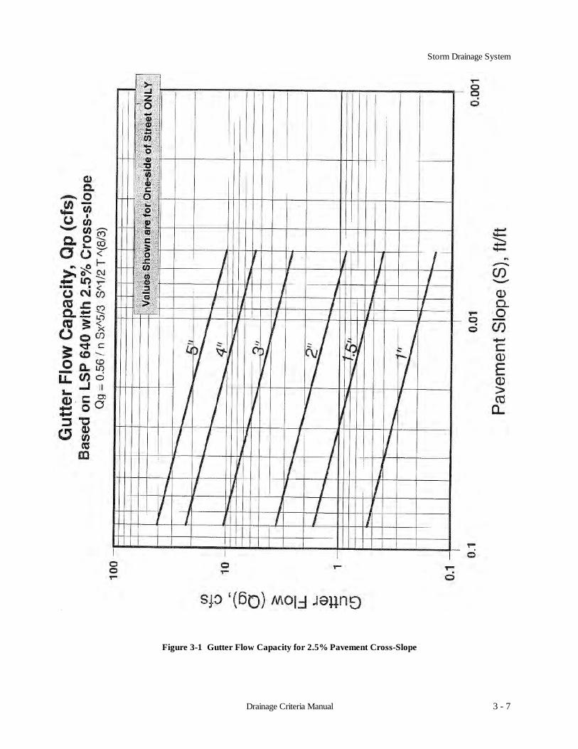
Gutter flow capacities for City of Lincoln standard street cross-sections are provided in Figure 3-1 for 2.5%pavement cross-slope and in Figure 3-2 for 3.0% pavement cross-slope. For non-standard applications, refer toSections 3.3.2 through 3.3.7.
3.3.2 Formula
The following form of Manning's Equation should be used to evaluate gutter flow hydraulics:
Q = [0.56 / n] Sx5/3 S1/2 T8/3 (3.1)
Where: Q = gutter flow rate (cfs)n = Manning's roughness coefficientSx = pavement cross slope (ft/ft)S = longitudinal slope (ft/ft)T = width of flow or spread (ft)
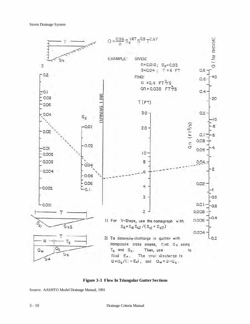
3.3.3 Nomograph
A nomograph for solving Equation 3.1 is presented Figure 3-3. Manning's n values for various pavement surfacesare presented in Table 3-2.
Storm Drainage System
3 - 7Drainage Criteria Manual
Figure 3-1 Gutter Flow Capacity for 2.5% Pavement Cross-Slope

Storm Drainage System
3 - 8 Drainage Criteria Manual
Figure 3-2 Gutter Flow Capacity for 3.0% Pavement Cross-Slope

Storm Drainage System
3 - 9Drainage Criteria Manual
3.3.4 Manning's n Table
Table 3-2 Manning's n Values For Street And Pavement Gutters
Type of Gutter or Pavement Range of Manning's nConcrete gutter, troweled finish 0.012Asphalt pavement: Smooth texture 0.013
Rough texture 0.016Concrete gutter with asphalt pavement: Smooth 0.013
Rough 0.015Concrete pavement: Float finish 0.014
Broom finish 0.016For gutters with small slopes, where sediment may accumulate, increase above values of n by 0.002Note: Estimates are by the Federal Highway AdministrationReference: USDOT, FHWA, HDS-3 (1961).
3.3.5 Uniform Cross Slope
The nomograph in Figure 3-3 is used with the following procedures to find gutter capacity for uniform cross slopes:
Condition 1: Find spread, given gutter flow.
1. Determine input parameters, including longitudinal slope (S), cross slope (Sx), gutter flow (Q), and Manning'sn.
2. Draw a line between the S and Sx scales and note where it intersects the turning line.
3. Draw a line between the turning line intersection point from Step 2 and the appropriate gutter flow value onthe capacity scale. If Manning's n is 0.016, use Q from Step 1 and the right scale on the capacity line. If theManning’s n is not 0.016, multiply Q and n from Step 1 and use the left scale on the capacity scale.
4. Read the value of the spread (T) at the intersection of the line from Step 3 and the spread scale.
Storm Drainage System
3 - 10 Drainage Criteria Manual
Figure 3-3 Flow In Triangular Gutter Sections
Source: AASHTO Model Drainage Manual, 1991

Storm Drainage System
3 - 11Drainage Criteria Manual
Condition 2: Find gutter flow, given spread.
1. Determine input parameters, including longitudinal slope(S), cross slope(Sx), spread(T), and Manning's n.
2. Draw a line between the S and Sx scales and note where it intersects the turning line.
3. Draw a line between the turning line intersection point from Step 2 and the appropriate value on the T scale.Read the value of Q (from the right side of the scale) or Qn (from the left side of the scale) from the intersectionof that line on the capacity scale.
4. For Manning's n values of 0.016, the gutter capacity (Q) from Step 3 is selected. For other Manning's n values,the gutter capacity times Manning’s n (Qn) is selected from Step 3 and divided by the appropriate n value togive the gutter capacity.
3.3.6 Composite Gutter Sections
Figure 3-4 in combination with Figure 3-3 can be used to find the flow in a gutter with width (W) less than the totalspread (T). Such calculations are generally used for evaluating composite gutter sections. Figure 3-4 provides a directsolution of gutter flow in a composite gutter section. The flow rate at a given spread or the spread at a known flow ratecan be found from this figure. Typical of graphical solutions, extreme care in using the figure is necessary to obtainaccurate results.
Condition 1: Find spread, given gutter flow.
1. Determine input parameters, including longitudinal slope (S), cross slope (Sx), depressed section slope (Sw),depressed section width (W), Manning's n, gutter flow (Q), and a trial value of the gutter capacity above thedepressed section (Qs).
2. Calculate the gutter flow in W (Qw), using the equation:
Qw = Q - Qs (3.2)
3. Calculate the ratios Qw/Q or Eo and Sw/Sx and use Figure 3-4 to find an appropriate value of W/T.
4. Calculate the spread (T) by dividing the depressed section width (W) by the value of W/T from Step 3.
5. Find the spread above the depressed section (Ts) by subtracting W from the value of T obtained in Step 4.
6. Use the value of Ts from Step 5 along with Manning's n, S, and Sx to find the actual value of Qs from Figure3-3.
7. Compare the value of Qs from Step 6 to the trial value from Step 1. If values are not comparable, select a newvalue of Qs and return to Step 1.

Storm Drainage System
3 - 12 Drainage Criteria Manual
Figure 3-4 Ratio Of Frontal Flow To Total Gutter Flow
Source: AASHTO Model Drainage Manual, 1991

Storm Drainage System
3 - 13Drainage Criteria Manual
Condition 2: Find gutter flow, given spread.
1. Determine input parameters, including spread (T), spread above the depressed section (Ts), cross slope (Sx), lon-gitudinal slope (S), depressed section slope (Sw), depressed section width (W), Manning's n, and depth of gutterflow (d).
2. Use Figure 3-2 to determine the capacity of the gutter section above the depressed section (Qs). Use the pro-cedure for uniform cross slopes (Condition 2), substituting Ts for T.
3. Calculate the ratios W/T and Sw/Sx, and, from Figure 3-4, find the appropriate value of Eo (the ratio of Qw/Q).
4. Calculate the total gutter flow using the equation:
Q = Qs / (1 - Eo) (3.3)
Where: Q = gutter flow rate (cfs)Qs = flow capacity of the gutter section above the depressed section (cfs)Eo = ratio of frontal flow to total gutter flow (Qw/Q)
5. Calculate the gutter flow in width (W), using Equation 3.2. 3.3.7 Examples
Example 1
Given: T = 8 ftSx = 0.025 ft/ftS = 0.01 ft/ftn = 0.015
Find: (1) Flow in gutter at design spread(2) Flow in width (W = 2 ft) adjacent to the curb
Solution: (1) From Figure 3-3, Qn = 0.03Q = Qn/n = 0.03/0.015 = 2.0 cfs
(2) Ts = 8 - 2 = 6 ft(Qn)2 = 0.014 (Figure 3-1) (flow in 6 ft width outside of width W)
Q = 0.014/0.015 = 0.9 cfs
Qw = 2.0 - 0.9 = 1.1 cfs
Flow in the first 2 ft adjacent to the curb is 1.1 cfs and 0.9 cfs in the remainder of the gutter.
Storm Drainage System
3 - 14 Drainage Criteria Manual
Example 2
Given: T = 6 ft Sw = 0.0833 ft/ft n = 0.014Ts = 6 - 1.5 = 4.5 ft S = 0.04 ft/ftSx = 0.03 ft/ft W = 1.5 ft
Find: Flow in the composite gutter
Solution: (1) Use Figure 3-3 to find the gutter section capacity above the depressed section.
Qsn = 0.017
Qs = 0.017/0.014 = 1.2 cfs
(2) Calculate W/T = 1.5/6 = 0.25 and
Sw/Sx = 0.0833/0.03 = 2.78
Use Figure 3-3 to find Eo = 0.64
(3) Calculate the gutter flow using Equation 3.3:
Q = 1.2/(1 - 0.64) = 3.3 cfs
(4) Calculate the gutter flow in width, W, using Equation 3.2:
Qw = 3.3 - 1.2 = 2.1 cfs
3.4 Storm Water Inlets
3.4.1 Overview
The primary aim of drainage design is to limit the amount of water flowing along the gutters or ponding at the sagsto quantities which will not interfere with the passage of traffic for the design frequency. This is accomplished byplacing inlets at such points and at such intervals to intercept flows and control spread. In this section, guidelines aregiven for designing roadway features as they relate to gutter and inlet hydraulics and storm drain design. Proceduresfor performing gutter flow calculations are based on a modification of Manning’s Equation. Inlet capacity calculationsare based on information contained in HEC-12 (USDOT, FHWA, 1984). Storm drain design is based on the use of therational formula.
Drainage inlets are located to limit the depth or spread on traffic lanes to allowable limits for the design storm. Gratesshould safely accommodate bicycle and pedestrian traffic where appropriate.
Inlets at vertical curve sags in the roadway grade should also be capable of limiting the spread to allowable limits.The width of water spread on the pavement should not be greater than the width of spread encountered on continuousgrades. Inlets should be located so that concentrated flow and heavy sheet flow will not cross traffic lanes, and shouldbe located just upgrade of pedestrian crossings and locations where the pavement slope reverses.
Inlets may be classified as being on a continuous grade or in a sump. The term “continuous grade” refers to an inletlocated on the street with a continuous slope past the inlet with water entering from one direction. The “sump” conditionexists when the inlet is located at a low point and water enters from both directions.
Storm Drainage System
3 - 15Drainage Criteria Manual
Inlets used for the drainage of paved or unpaved surfaces can be divided into two major classes. These classes are:
1. Grate Inlets - These inlets include grate inlets consisting of an opening covered by one or more grates, andslotted inlets consisting of a pipe cut along the longitudinal axis with a grate of spacer bar to form slot openings.
2. Curb-Opening Inlets - These inlets are vertical openings in the curb covered by a top slab.
3.4.2 Criteria
The following criteria shall be used for inlet design:
Average ReturnLand Use Frequency (years)
Residential Areas 5Commercial, Industrial, and Arterial Roads 10
Inlets! 72-inch straight and canted inlets shall be used in the public street system! Grate inlets may be used for parking lot drains, area drains, etc.! Flow in the gutter should not exceed five (5) inches.! Inlets should be placed at the low points in the street grade.
Design charts for standard City of Lincoln inlets are provided in the Chapter 3 of the Manual. The location of the firstinlet shall be determined by a trial and error process based upon a point where the maximum depth of flow in the gutteris five inches. Subsequent inlets downstream from the initial inlets shall be located at or before points where the depthof flow in gutter is five inches. Usually inlets shall be placed at the ends of radii and/or before crosswalks atintersections. Inlets which the study shows are needed at locations other than at intersections shall generally be centeredbetween lot lines. Inlets shall be installed at the upper end of all storm drain lines and at low points in the street grades.It may be necessary at some locations to use more than one inlet to pick up the contributing flow. Canted inlets Inletsshall not be placed along intersection radii, unless approved by the Director of Public Works and Utilities.
Concrete valley gutters may be used across roadways at T-intersections of local roadways, if the calculated depth offlow for the minor system design flow in the curb and gutter section immediately upstream is less than 5 inches and ifthere is no existing or proposed storm drain conduit extended to the intersection. The pavement cross-slope on the“uphill” lane of the minor approach shall be reduced at a gradual rate from 3% to 1% to allow drainage of the “uphill”gutter flow line through the return. No valley gutters shall be used across collector or arterial roadways.
Curb and gutter grades that are equal to pavement slopes shall not exceed 8 percent or fall below 0.5 percent withoutapproval from the Director of Public Works and Utilities.
The detailed procedures and necessary charts to design inlets are described in Chapter 3 of the Manual. Curb andgutter installation shall be in accordance with the current Lincoln Standard Plans and Specifications.
3.4.3 Manholes
Manholes shall be installed at the upper end of all storm drain lines and at all changes in grade, size, or alignment.The recommended maximum spacing is 600 feet for storm drain lines, 36 inches and less in diameter. Greater spacingsthan this will require approval by the Director of Public Works and Utilities. The crowns of all storm drain pipes enteringand leaving a junction shall be at the same elevation. Laterals from a storm drain inlet to the main storm drain line maybe tapped directly into the main storm drain line if the diameter of the lateral does not exceed one-half the diameter ofthe pipe being tapped. If the diameter of the lateral does exceed one-half the diameter of the pipe being tapped, a stormdrain manhole or inlet will be required. The crown of the lateral pipe shall match the crown of the main storm drain pipe.Storm drain manhole shall be constructed in accordance with the most current City Standard Drawings and Specifica-tions.

Storm Drainage System
3 - 16 Drainage Criteria Manual
3.4.4 Grate Inlets
A design chart for the three standard City of Lincoln grate inlets plus curb inlet in a sump condition is provided inFigure 3-5.
The capacity of an inlet depends upon its geometry and the cross slope, longitudinal slope, total flow, depth of flowand pavement roughness. The depth of water next to the curb is the major factor in the interception capacity of bothgutter inlets and curb opening inlets. At low velocities, all of the water flowing in the section of gutter occupied by thegrate, called frontal flow, is intercepted by grate inlets, and a small portion of the flow along the length of the grate,termed side flow, is intercepted. On steep slopes, only a portion of the frontal flow will be intercepted if the velocityis high or the grate is short and splash-over occurs. For grates less than 2 feet long, intercepted flow is small. Inlet inter-ception capacity has been investigated by agencies and manufacturers of grates. For inlet efficiency data for varioussizes and shapes of grates, refer to Hydraulic Engineering Circular No. 12 Federal Highway Administration and inletgrate capacity charts prepared by grate manufacturers.
3.4.5 Curb Inlets
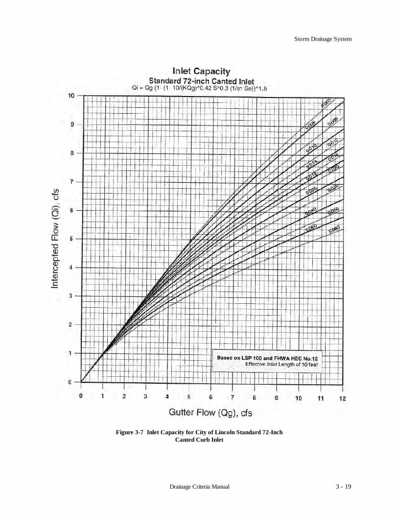
Capacities for the standard City of Lincoln 72-inch straight and canted curb inlets are provided in Figures 3-6 and 3-7.Capacity of 48-inch straight inlets used for median drainage is provided in Figure 3-8. In extraordinary conditions, non-standard designs may be needed. Refer to “Drainage of Highway Pavements” Hydraulic Engineering Circular No. 12.A sample Inlet Design Computation Form is provided in Figure 3-9.
Formulas for inlet capacities
Inlet capacity in a sump is controlled by two flow conditions, weir flow and orifice flow. Figure 3-5 was developed usingthe following two equations:
Sump conditions
Qw = 3.0 Pd1.5 (3.4a)and
Qo = 0.67 A (2gd) 0.5 (3.4b)
Where, Qw = weir capacity (cfs) and, Qo = orifice capacity (cfs)P = perimeter (ft) A = clear opening area (sf)d = depth (ft) g = acceleration of gravity - 32.2 ft/s2
d = depth (ft)
Curb inlet interception capacity is the flow intercepted by an inlet under a given set of conditions. The efficiency of aninlet changes with changes in cross slope, longitudinal slope, total gutter flow, and to a lesser extent, pavementroughness.
Curb inlets on grade formulaQi = Qg (1- (1-EL /kQg) 0.42 s 0.3 (1/ n Se) 1.8 (3.5)
Where, Qi = inlet capacity (cfs)Qg= flow in the gutter (cfs) s = pavement slope (ft/ft)EL = effective length of inlet (ft) n = Manning’s roughness coefficientk = 0.6 for US customary units Se = composite slope of cross-section (ft/ft)
3.4.6 Flared End Sections
Capacities for flared end sections shall be determined using the procedures provided in Chapter 4 - Design of Culverts.

Storm Drainage System
3 - 17Drainage Criteria Manual
Figure 3-5 Capacity for City of Lincoln Standard Grate Inlets

Storm Drainage System
3 - 18 Drainage Criteria Manual
Figure 3-6 Inlet Capacity for City of Lincoln Standard 72-InchStandard Straight Curb Inlet
Storm Drainage System
3 - 19Drainage Criteria Manual
Figure 3-7 Inlet Capacity for City of Lincoln Standard 72-InchCanted Curb Inlet

Storm Drainage System
3 - 20 Drainage Criteria Manual
Figure 3-8 Inlet Capacity for City of Lincoln Standard 48-InchStraight Curb Inlet

Storm Drainage System
3 - 21Drainage Criteria Manual
Figure 3-9 Inlet Design Computation Form
Storm Drainage System
3 - 22 Drainage Criteria Manual
3.5 Storm Drains
3.5.1 Introduction
After the tentative location of inlets has been determined and the inlets sized, the next logical step is the computationof the rate of discharge to be carried by each drain pipe and the determination of the size and gradient of pipe requiredto carry this discharge. The procedure is carried out for each section of pipe starting at the most upstream inlet andproceeding downstream. It should be recognized that the rate of discharge to be carried by any particular section of drainpipe is not necessarily the sum of the inlet design discharge rates of all inlets above that section of pipe, but as a generalrule is somewhat less than this total. In other words, the inlets are designed to assure that the full pipe capacity isutilized. It is useful to understand that the time of concentration is most influential and as the time of concentrationgrows larger, the proper rainfall intensity to be used in the design grows smaller.
For ordinary conditions, drain pipes should be sized on the assumption that they will flow full or practically full underthe design discharge but will not be placed under pressure head. The Manning Formula is recommended for capacitycalculations.
3.5.2 Design Criteria
The standard recommended maximum and minimum slopes for storm drains shall conform to the following criteria:
1. The maximum hydraulic gradient shall not produce a velocity that exceeds 20 feet per second.
2. The minimum desirable physical slope shall be 0.5 percent or the slope which will produce a velocity of 3.0feet per second when the storm drain is flowing full, whichever is greater.
In order to determine if design flows can be accommodated by the storm drains system without causing flooding, orcausing flows to exit the system at unacceptable locations, the designer shall determine the hydraulic gradient. Thefollowing design criteria shall be followed when determining the elevation along the hydraulic grade line (HGL):
! The hydraulic grade line shall be 0.75 feet below the intake lip of any affected inlet, any manhole cover,or any entering nonpressurized system.
! The energy grade line shall not rise above the intake lip of any affected inlet, any manhole cover or anyentering nonpressurized system.
All storm drains should be designed such that velocities of flow will not be less than 3.0 feet per second at designflow, with a minimum slope of 0.5 percent. For very flat flow lines the general practice is to design components so thatflow velocities will increase progressively throughout the length of the pipe system.
Location and AlignmentIn new subdivisions the center of the street is reserved for storm drain system. When construction of a storm drain
system is necessary in the older parts of the town, the location is determine by the City. No structures may be placedover a public storm drain system.
Depth of CoverThe desired depth of cover above a storm drain pipe shall be 2 to 3 feet, with 1.5 feet being the absolute minimum
at an inlet location. Depth of cover greater than 3 feet shall be avoided due to the possibility of the storm drain blockingaccess of sanitary sewer service lines to the main sanitary sewer lines.
Material and JointsOnly reinforced concrete storm drain pipe shall be used within the City limits, unless approved by the Director of
Public Works and Utilities. Construction of pipe and joint shall conform to the City of Lincoln Standard Specification.
Bar Grates on End SectionsAn open pipe inlet from an open channel (similar to a culvert inlet) into a closed pipe storm drain shall be designed
and constructed with flared end sections with a bar grate. No bar grate is required on the end section of a pipe outlet intoan open channel unless directed by the Director of Public Works and Utilities.

Storm Drainage System
3 - 23Drainage Criteria Manual
3.5.3 Design Procedures
The design of storm drain systems is generally divided into the operations listed below. Supporting documentationshall be submitted with development plans for review:
1. The first step is the determination of inlet location and spacing as outlined earlier in this chapter.
2. The second step is the preparation of a plan layout of the storm drain system establishing the following designdata:
a. Location of storm drains.b. Direction of flow. c. Location of manholes. d. Location of existing facilities such as water, gas, or underground cables.
3. The design of the storm drain system is then accomplished by determining drainage areas, computing runoffby rational method, and computing the hydraulic capacity by Manning's equation.
4. The storm drain design computation sheet (Figure 3-12) shall be used to summarize the preliminary systemdesign computations.
5. The hydraulic grade line computation from Figure 3-14 shall be used to determine the hydraulic gradient. Thehydraulic grade line profile shall be provided on the storm drain system plans for the minor design storm.
3.5.4 Capacity
Storm drain capacity for reinforced concrete pipe can be determined using Figure 3-13. For non-standard applications,hydraulic capacity can be determined using the information provided below.
Formulas for Gravity and Pressure Flow
The most widely used formula for determining the hydraulic capacity of storm drain pipes for gravity and pressureflows is the Manning Formula and it is expressed by the following equation:
V = [1.486 R2/3S1/2]/n (3.6)
Where: V = mean velocity of flow (ft/s)R = the hydraulic radius (ft) - the area of flow divided by the wetted flow surface or wetted perimeter (A/WP)S = the slope of hydraulic grade line (ft/ft)n = Manning's roughness coefficient
In terms of discharge, the above formula becomes:
Q = [1.486 AR2/3S1/2]n (3.7)
Where: Q = rate of flow (cfs)A = cross sectional area of flow (ft2)
For pipes flowing full, the above equations become:
V = [0.590 D2/3S1/2]/n (3.8)Q = [0.463 D8/3S1/2]/n (3.9)
Where: D = diameter of pipe (ft)
The Manning's equation can be written to determine friction losses for storm drain pipes as:
Hf = [2.87 n2V2L]/[S4/3] (3.10)

Storm Drainage System
3 - 24 Drainage Criteria Manual
Hf = [29 n2LV2]/[(R4/3)(2g) (3.11)
Where: Hf = total head loss due to friction (ft)D = diameter of pipe (ft)L = length of pipe (ft)V = mean velocity (ft/s)R = hydraulic radius (ft)g = acceleration of gravity - 32.2 ft/s2
3.5.4.1 Street Right-of-way and Overland Swale
Street right-of-ways convey the portion runoff in excess of pipe capacity, whether planned or not. Street right-of-waycapacity is determined using Manning’s equation for open channel flow conditions.
Q = 1.486 AR2/3S1/2 (3.6) n
The City of Lincoln uses standard street and right-of-way cross-sections for municipal streets, the formula can besimplified to:
Q = K S1/2, where conveyance constant, K = 1.486 AR2/3
n
Area, wetted perimeter, and roughness coefficient are constant, the only variable being the street slope.
(i.e., For residential For overland swales
A = 21.662 square feet, A = 22.5 square feet,R = 0.360 feet, and R = 0.149 feet, andn(wtd) = 0.026 n = 0.032)
The following table gives the conveyance constants for residential, commercial and major two-lane streets and a 30-foot wide swale with 10:1 side slopes.
Table 3-6 Conveyance Constants for Standard Street Right-of-Ways and 30' Swale
Residential 620Business with parking 970Business without parking 790Major two-lane 110030-foot Swale 780

Storm Drainage System
3 - 25Drainage Criteria Manual
Figure 3-10 Swale Capacity Chart

Storm Drainage System
3 - 26 Drainage Criteria Manual
Table 3-7 Values of 1.486/n x A x Rb for Circular Concrete and Corrugated Metal PipeSource: ACPA, Design Data 4, Hydraulic Capacity of Sewers, Table III

Storm Drainage System
3 - 27Drainage Criteria Manual
Figure 3-11 Right-of-Way Capacity Chart

Storm Drainage System
3 - 28 Drainage Criteria Manual
Column (1) - Contributing area at the point-of-studyColumn (2) - Coefficient of runoff for Rational Method, see Table 2-3 and Table 2-4Column (3) - Product of area and coefficient of runoff, C x A or Col. (3) = Col. (1) x Col. (2)Column (4) - Summation of Col. (3) for all contributing drainage basins to the point-of-studyColumn (5) - Time of concentration to the point of study for the drainage basin or the accumulated travel time of the
aggregate drainage basins, whichever is greater, TcColumn (6) - Minor storm rainfall intensity, from Figure 2-3
or I = 42.456 F0.1943 / (Tc+14.0) 0.7912; F = Average Return FrequencyColumn (7) - Peak rate of flow for minor storm runoff at the point-of-study, Qr = CIA
or Col. (7) = Col. (4) x Col. (6)Column (8) - Preliminary pipe slopeColumn (9) - Pipe length segment from center to center of structuresColumn (10) - Preliminary pipe size required to convey minor storm runoff. Indicate diameter or span x riseColumn (11) - Capacity of pipe for full flow conditions
Q = 1.486 A Rb S½ or Figure 3-13 0.013
Column (12) - Velocity in the pipe for full-flow conditions, V = Q/A or Figure 3-13Column (13) - Time of travel in pipe segment, Tp = L or Col. (13) = Col. (9) / Col. (12) / 60
60V
Column (14) - 100-year storm rainfall intensity, from Figure 2-3or I100 = 103.882 / (Tc + 14)0.7912
Column (15) - Peak rate of flow for 100-year storm runoff at the point-of-study, Q100 = CI100A or Col. (15) = Col. (4) x Col. (14)
Column (16) - Slope of overland flow route for 100-year storm runoffColumn (17) - Street and right-of-way widthColumn (18) - Street capacity for flow to the limits of right-of-way for LSP-640
Q = 1.486 A Rb S½
n
K = 1.486 A Rb, is constant for full depth flow conditions. n
K for each standard street and ROW width is provided below (e.g., K 26/60 for a 26' street with a 60-foot ROW)
Residential K(26/60) = 620 Business with parking K(38/72) = 970Major two lane K(32/80) = 1100 Business without parking K(33/66) = 79030-foot Swale Kswale = 780or See Figure 3-10 or Figure 3-11
Column (19) - Combined capacity of the street and minor drainage systems must be equal to or greater than the peakrate of flow for the 100-year storm.
Column (20) - Swale width, where flow from major storms is not contained in the street system an overland flowroute must be provided.
Column (21) - Combined capacity of the swale and minor systems must be equal to or greater than the peak rate offlow for the major storm.
Column (22) - Clarifying comments

Storm Drainage System
3 - 29Drainage Criteria Manual
Figure 3-12 Storm Drain Computation Form

Storm Drainage System
3 - 30 Drainage Criteria Manual
Figure 3-13 Nomograph For Solution of Manning’s Formula In Storm Drains

Storm Drainage System
3 - 31Drainage Criteria Manual
3.5.5 Hydraulic Gradient
In order to determine if design flows can be accommodated by the storm drains system without causing flooding, orcausing flows to exit the system at unacceptable locations, the designer shall determine the hydraulic gradient.Computing the hydraulic gradient will determine the elevation to which water will rise in inlets and manholes. Thefollowing sections provide the necessary procedures and equations to determine the hydraulic gradient.
3.5.5.1 Friction Losses
Energy losses from pipe friction may be determined by rewriting the Manning equation.
Sf = [Qn/1.486 A(R2/3)]2 (3.12)
Then the head losses due to friction may be determined by the formula:
Hf = SfL (3.13)
Where: Hf = friction head loss (ft)Sf = friction slope (ft/ft)L = length of outflow pipe (ft)
3.5.5.2 Velocity Head Losses
From the time storm water first enters the sewer system at the inlet until it discharges at the outlet, it will encountera variety of hydraulic structures such as inlets, manholes, junctions, bends, contractions, enlargements and transitions,which will cause velocity head losses. Velocity losses may be expressed in a general form derived from the Bernoulliand Darcy-Weisback equations.
H = KV2/2g (3.14)
Where: H = velocity head loss (ft)K = loss coefficient for the particular structureV = velocity of flow (ft/s)g = acceleration due to gravity (32.2 ft/s)
3.5.5.3 Entrance Losses
Following are the equations used for entrance losses.
Htm = V2/2g (3.15)He = KV2/2g (3.16)
Where: Htm = terminal (beginning of run) loss (ft)He = entrance loss for outlet structure (ft)K = 0.5 (assuming square-edge)(Other terms defined above.)

Storm Drainage System
3 - 32 Drainage Criteria Manual
3.5.5.4 Junction Losses
Incoming Opposing Flows
The head loss at a junction, Hj1 for two almost equal and opposing flows meeting head on with the outlet directionperpendicular to both incoming directions, head loss is considered as the total velocity head of outgoing flow.
Hj1 = (V2)/2g (3.17)
Where: Hj1 = junction losses (ft)(Other terms are defined above.)
Changes in Direction of Flow
When main storm drain pipes or lateral lines meet in a junction, velocity is reduced within the chamber and specifichead increases to develop the velocity needed in the outlet pipe. The sharper the bend (approaching 90o) the more severethis energy loss becomes. When the outlet conduit is sized, determine the velocity and compute head loss in the chamberby the formula:
Hb = Kb(V2)/2g (3.18)
Where: Hb = bend head loss (ft)Kb = junction loss coefficient
The following Table 3-8 lists the values of Kb for various changes in flow direction and junction angles.
Table 3-8 Values Of Kb For Change In Direction Of Flow In Lateral
K Degree of Turn (In Junction)
0.19 150.35 300.47 450.56 600.64 750.70 90 and greater
K values for other degree of turns can be obtained by interpolating between values.
Table 3-9 lists the values for the junction loss coefficient for various conditions at pipe junctions.
Table 3-9 Values Of K At Junctions
For no bends at junctions - K = 0.20For bends at junctions of 25 degrees - K = 0.30For bends at junctions of 45 degrees - K = 0.40For bends at junctions of 90 degrees - K = 0.60For junctions of three pipes - K = 0.80For junctions of four or more pipes - K = 1.00

Storm Drainage System
3 - 33Drainage Criteria Manual
Several Entering Flows
The computation of losses in a junction with several entering flows utilizes the principle of conservation of energy.For a junction with several entering flows, the energy content of the inflows is equal to the energy content of outflowsplus additional energy required by the collision and turbulence of flows passing through the junction. The total junctionlosses can be determined from equation 3-17. See also Figure 3-14.
Hj2 = [(Q4V42)-(Q1V1
2)-(Q2V22)+(KQ1V1
2)]/(2gQ4)] (3.19)
Where: Hj2 = junction losses (ft)Q = discharges (cfs)V = horizontal velocities (ft/s) (V3 is assumed to be zero)g = acceleration due to gravity (32.2 ft/s2)K = bend loss factor
Where subscript nomenclature is as follows:
Q1 = 90o lateral (cfs)Q2 = straight through inflow (cfs)Q3 = vertical dropped-in flow from an inlet (cfs)Q4 = main outfall = total computed discharge (cfs)V1,V2,V3,V4 are the horizontal velocities of foregoing flows, respectively, in feet per secondV3 assumed to be = 0
Also Assume:
! Hb = K(V12)/2g for change in direction.
! No velocity head of an incoming line is greater than the velocity head of the outgoing line.! Water surface of inflow and outflow pipes in junction to be level.
When losses are computed for any junction condition for the same or a lesser number of inflows, the above equationwill be used with zero quantities for those conditions not present. If more directions or quantities are at the junction,additional terms will be inserted with consideration given to the relative magnitudes of flow and the coefficient of velo-city head for directions other than straight through.
3.5.5.5 Summary
The final step in designing a storm drain system is to check the hydraulic grade line (HGL) as described in the nextsection of this chapter. Computing the HGL will determine the elevation, under design conditions, to which water willrise in various inlets, manholes, junctions, and etc. The following design criteria shall be followed when determiningthe elevation at the HGL:
! The hydraulic grade line shall be 0.75 feet below the intake lip of any affected inlet, any manhole cover,or any entering nonpressurized system.
! The energy grade line shall not rise above the intake lip of any affected inlet, any manhole cover or anyentering nonpressurized system.
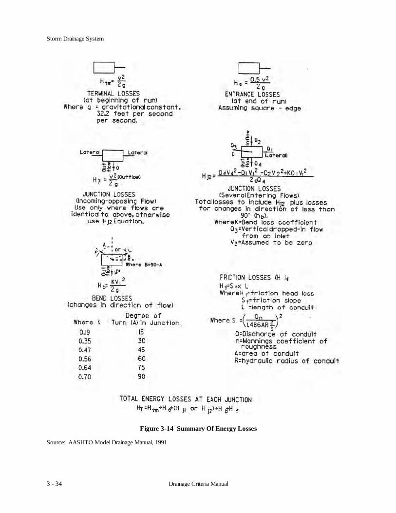
A summary of energy losses which shall be considered is presented in Figure 3-14.
Storm Drainage System
3 - 34 Drainage Criteria Manual
Figure 3-14 Summary Of Energy Losses
Source: AASHTO Model Drainage Manual, 1991

Storm Drainage System
3 - 35Drainage Criteria Manual
Figure 3-15 Energy And Hydraulic Grade Lines For Storm drain Under Constant Discharge
Source: AASHTO Model Drainage Manual, 1991

Storm Drainage System
3 - 36 Drainage Criteria Manual
3.5.6 Hydraulic Grade Line Design Procedure
The hydraulic grade line is calculated beginning at the system outlet proceeding upstream. Conditions expected atthe outlet for the minor design storm shall be used for the starting water surface elevation.
Column (1) - Design flow to be conveyed by pipe segment.Column (2) - Length of pipe segment.Column (3) - Pipe Size; Indicate pipe diameter or span x rise.Column (4) - Constant K, from American Concrete Pipe Association Design Data:
Kp = 1,486 ARb ; or from Table 3-7 n
Column (5) - Flowline Outlet Elevation of pipe segment.Column (6) - Flowline Inlet Elevation of pipe segment.Column (7) - Barrel Area is the full cross sectional area of the pipe.Column (8) - Barrel Velocity is the full velocity in the pipe as determined by:
V = Q/A or Col. (8) = Col. (1) / Col. (7)
Column (9) - Barrel Velocity Head = V2/2g or Col. (8)2 / 2gWhere, g = 32.2 ft/sec2 (acceleration due to gravity)
Column (10) - Tailwater (TW) Elevation; this is the water surface elevation at the outlet of the pipe segment. Ifthe pipe’s outlet is not submerged by the TW and the TW depth is less than (D+dc)/2, set the TWelevation equal to (D+dc)/2. This will keep the analysis simple yet still obtain reasonable results(D = pipe barrel height and dc = critical depth, both in ft. See Appendix 4-B for determination ofdc).
Column (11) - Friction Loss = S1 x L or S1 x Col. (2)Where, S1 is the friction slope or head loss per lineal foot of pipe as determined by Manning’sEquation expressed in the form:
S1 = Sf = (Q / Kp)2; K from Table 3-7
Column (12) - Hydraulic Grade Line (HGL) Elevation just inside the entrance of the pipe barrel; this isdetermined by adding the friction loss to the TW elevation:
Col. (12) = Col. (11) + Col. (10)
If this elevation falls below the pipe’s inlet crown, it no longer represents the true HGL whencomputed in this manner. The true HGL will fall somewhere between the pipe’s crown and eithernormal flow depth or critical flow depth, whichever is greater. To keep the analysis simple andstill obtain reasonable results (i.e., erring on the conservative side), set the HGL elevation equal tothe crown elevation.
Column (13) - Entrance Head Loss = Ke x V2 / 2g or Ke x Col. (9) Where, Ke = Entrance Loss Coefficient (0.5assuming square-edge ) This is the head lost due to flow contractions at the pipe entrance.
Column (14) - Exit Head Loss = 1.0 x V2 / 2g or 1.0 x Col. (9)This is the velocity head lost or transferred downstream.

Storm Drainage System
3 - 37Drainage Criteria Manual
Column (15) - Outlet Control Elevation = Col. (12) + Col. (13) + Col. (14)This is the maximum headwater elevation assuming the pipe’s barrel and inlet/outletcharacteristics are controlling capacity. It does not include structure losses or approach velocityconsiderations.
Column (16) - Inlet Control Elevation (See Figure 4-2 for computation of inlet control on culverts). This is themaximum headwater elevation assuming the pipe’s inlet is controlling capacity. It does notinclude structure losses or approach velocity considerations.
Column (17) - Approach Velocity Head; this is the head (energy) being supplied by the discharge form anupstream pipe or channel section, which serves to reduce the headwater elevation. If the dischargeis from a pipe, the approach velocity head is equal to the barrel velocity head computed for theupstream pipe. If the upstream pipe outlet is significantly higher in elevation (as in a dropmanhole) or lower in elevation such that its discharge energy would be dissipated, an approachvelocity head of zero should be assumed.
Column (18) - Bend Head Loss = Kb x V2 / 2g or kb x Col. (17)Where, Kb = Bend Loss Coefficient (from Table 3-7). This is the loss of head/energy required tochange direction of flow in an access structure.
Column (19) - Junction Head Loss; this is the loss in head (energy) that results from the turbulence created whentwo or more streams are merged into one within the access structure. Table 3-8 can be used todetermine junction loss coefficients for use in the following equations given in Figure 3-14.
Column (20) - Headwater (HW) Elevation; this is determined by combining the energy heads in Columns 17, 18,and 19 with the highest control elevation in either Column 15 or 16, as follows:
Col. (20) = Col. (15 or 16) - Col. (17) + Col. (18) + Col. (19)
Column (21) - Top of curb elevation at an inlet or rim elevation at a storm sewer manhole.
Column (22) - Inlet capacity is reduced if the hydraulic gradeline elevation interferes with the napping effectduring weir or orifice flow conditions.

Storm Drainage System
3 - 38 Drainage Criteria Manual
Figure 3-16 Hydraulic Grade Line Computation Form

Storm Drainage System
3 - 39Drainage Criteria Manual
Figure 3-17 Hypothetical Storm Drain System Layout

Storm Drainage System
3 - 40 Drainage Criteria Manual
3.6 Computer Programs
There are numerous proprietary and non-proprietary computer models that may be used to design components ofthe minor storm drainage system. The reader is referred to the user manual for any particular program to determineits suitability for solving storm drainage problems.

Storm Drainage System
3 - 41Drainage Criteria Manual
References
U. S. Department of Transportation, Federal Highway Administration, 1984. Drainage of Highway Pavements. Hydraulic Engineering Circular No. 12.
American Concrete Pipe Association, March 1968, Design Data.