storm drainage detention master plan
TRANSCRIPT

Storm Drainage
Detention
Master Plan
Submitted in compliance with
Condition of Approval
N.2.b of the
Stanford 2000
General Use Permit
Prepared by Nolte Associates
April 10, 2001

Table of Contents
Page
(11/18/11) C:\DOCUME~1\careyc\LOCALS~1\Temp\Temporary Directory 2 for DetentionReport (2).zip\Report_final_TOC.doc
i
1. Introduction
Background ....................................................................................................... 1-1
Scope of Work .................................................................................................. 1-1
Study Area ......................................................................................................... 1-1
2. Summary ................................................................................................................ 2-1
3. Design Criteria and Calculation Methodology
Campus Setting ................................................................................................. 3-1
Design Storm Event Definition ......................................................................... 3-1
Design Criteria .................................................................................................. 3-2
Calculation Methodologies ............................................................................... 3-2
Detention/Storage Methodology ........................................................... 3-2
4. Existing Drainage Systems and Identified Problems
Natural Topography ......................................................................................... 4-1
Off-Site Drainage Systems ................................................................................ 4-1
On-Site Drainage Systems ................................................................................ 4-2
Land Use Changes ............................................................................................ 4-3
5. Hydrologic/Hydraulic Analysis
Storage Detention Requirements ...................................................................... 5-1
Alternative Locations ........................................................................................ 5-3
Location Constraints ............................................................................. 5-3
Suggested Sites ..................................................................................... 5-4
Site / Location Interactions ................................................................... 5-5
Design Storm Interactions ..................................................................... 5-5
Site Specific Recommendations ....................................................................... 5-6
Serra Street at El Camino Detention Basins ......................................... 5-6
Serra Street at Campus Drive East Detention Basins ........................... 5-6
West Campus Detention Basins ............................................................ 5-6
Quarry Road Detention Basins.............................................................. 5-6
Detention Basin Capacity Use Documentation ................................................. 5-7
Appendix 1. Impervious Area Allocation to Drainage Basins

1 - 1
(11/18/2011) c:\docume~1\careyc\locals~1\temp\temporary directory 3 for detentionreport (2).zip\report_final1_introduction.doc
1. INTRODUCTION
BACKGROUND
Stanford University is preparing an Overland Flow Master Plan for its storm runoff and
flood control system, specifically those elements of the system that provide protection of
Campus facilities when flows exceed the capacity of the normal on-site storm drainage
system. Recently, the University received approval of the Stanford Community
Plan/General Use Permit, which approves academic and residential development.
Condition of Approval N.2.b of the Stanford 2000 General Use Permit required Stanford
University to mitigate the potential for increased storm water runoff.
SCOPE OF WORK
This study has been conducted to master plan regional management of surface runoff by
using detention facilities that will facilitate Campus growth, while maximizing the
protection of the Campus and the surrounding area. This report will present an analysis
of runoff and recommendations for new detention facilities that are capable of integrating
storm water protection with existing and future Campus functions and space needs. Joint
use with athletic and recreational activities will be specifically considered. The
recommendations will satisfy the condition that storm drainage improvements will be
sufficient to ensure that runoff levels will not increase over the existing peak levels and
cause downstream flooding.
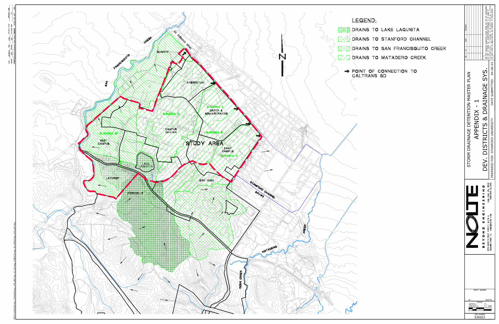
STUDY AREA
The Campus Area investigated in this study is illustrated in Figure 1-1. Upland areas that
are tributary to the study area have also been analyzed.


2 - 1 (11/18/2011) c:\docume~1\careyc\locals~1\temp\temporary directory 4 for detentionreport (2).zip\report_final2_conclusion.doc
2. Summary
The Campus area covered by this study drains to Matadero Creek and San Francisquito
Creek. The specific limits are presented in Figure 1-1. The Campus is continuing to
develop, and there is a need to protect both Campus facilities and neighboring
communities from increases in surface runoff.
The following design criteria are proposed for the Stanford University Campus:
Runoff from storms up through the 10-year event should be collected and
conveyed by storm drainage inlets, pipes, and ditches. At this level, standing
water and surface flow of runoff should be minimized.
Runoff from storms in excess of the 10-year event, up through the 100-year
event, should be managed using established overland flow paths that prevent
damage to Campus facilities.
Storm water detention basins shall be implemented to prevent increases in the
peak flow rates, caused by changes in Campus surface runoff conditions, from
leaving the Campus. The basins shall provide detention for both the 10-year
and 100-year storms.
The Corps of Engineers’ HEC-1 Flood Hydrograph computer program was used to model
existing and future runoff and detention storage facilities.
The approved Stanford Community Plan/General Use Permit proposes modifications and
additions to the Campus. Of the total of 1,606 acres in the study area, approximately
38.77 acres of currently pervious acres (undeveloped and unpaved) on the Campus would
be changed to impervious area.
For the Matadero Creek Watershed portion of the Campus, 0.08 acre-ft of detention
storage is required to reduce the projected 100-year peak flow for the future developed
condition to the current peak flow. To reduce the projected 10-year flow increase to
current levels, 0.08 acre-ft of detention storage is needed.
For the San Francisquito Creek Watershed, 0.21 acre-ft of detention storage is required to
reduce the projected 100-year peak flow for the future developed condition to the current
peak flow. To reduce the projected 10-year flow increase to current levels, 0.12 acre-ft of
detention storage is needed. These volumes assume the detention basins are located at the
downstream end of the drainage area.
Five detention basin systems are recommended to attenuate increases in flows from
Campus development proposed by the approved Stanford Community Plan/General Use
Permit and possible future development. The basin locations are presented in Figure 5-1.

2 - 2 (11/18/2011) c:\docume~1\careyc\locals~1\temp\temporary directory 4 for detentionreport (2).zip\report_final2_conclusion.doc
The Serra Street at El Camino Detention Basin location is in the Matadero Creek
Watershed portion of the Campus. A two-basin system is recommended at this location
to reduce flows for both the 10-year and the 100-year event.
The Serra Street at Campus Drive East Detention Basin location is also in the Matadero
Creek Watershed portion of the Campus. A single basin system is recommended at this
location to reduce flows from the 100-year event.
The West Campus Detention Basin locations are in the San Francisquito Creek
Watershed portion of the Campus. Two-stage basin systems or two-basin systems to
reduce flows for both the 10-year and the 100-year are recommended at these locations.
These detention basin systems will reduce off-site flows, as well as reduce flows to
Campus drainage facilities.
The Quarry Road Detention Basin locations are in the San Francisquito Creek Watershed
portion of the Campus. The locations are only conceptual in plan and five sites are
indicated. The specific location will be selected at the time of initial design. One or
more of the sites may be used to achieve the full protection desired. The sites are
envisioned as either two-stage basins or two-basin systems that will provide reductions in
flow near the source for both the 10-year and 100-year events.
The specific size and configuration of the basins will be selected during the design
process. Basins located close to the project site need to be larger than basins located at
the downstream end of the drainage area. The basin locations near the project site,
however, may be able to minimize improvements to the existing piped storm drainage
system between the project site and the downstream end of the drainage basin.
The proposed detention basin locations are large enough to provide flow reductions for
current and future growth needs. Each of the basins may be sized to meet the needs of a
specific project or to accommodate several future projects within the watershed. Since
the joint use of the sites is a significant factor in determining the size of a basin, any one
of the basins may provide a significant reserve of peak flow attenuation capacity.
The capacity of a detention basin to reduce peak flows will be documented at the time the
permit for construction of the detention basin is submitted to the County of Santa Clara
for approval. This capacity will be equated to a specific number of square feet of
impervious area for which the detention basin will attenuate flow and will be designated
as a reserve of impervious area for use by future development. This reserve of
impervious area will be reduced as campus development projects are constructed. The
permit for each individual development project will identify the detention basin that is
providing the flow attenuation, state the change in impervious area caused by the project,
and indicate the balance in the reserve of impervious area for the identified basin before
and after the project.

3 - 1
(11/18/2011) c:\docume~1\careyc\locals~1\temp\temporary directory 5 for detentionreport (2).zip\report_final3_criteriaa.doc
3. DESIGN CRITERIA AND CALCULATION METHODOLOGY
In this section, the design criteria will be presented along with the methodology used to
perform the required calculations in this report. The design criteria will include the
setting for the facilities that are being protected, the frequency event that is used for
planning, and drainage principles that are applicable to these systems. The methodology
and assumptions for use in calculating runoff detention volumes using the Corps of
Engineers’ HEC-1 will also be presented.
In this report two terms will be used to describe surface runoff or the analysis of runoff.
These terms are hydrology and hydraulics. The following definitions are provided for
clarity:
Hydrology refers to the calculation of the quantity of runoff.
Hydraulics refers to the calculation or quantification of the water conveying
capacity of the storm drainage systems.
CAMPUS SETTING
Drainage facilities require space and occupy land. Drainage facilities should be designed,
when possible, to share the land with other uses such as parking, roadways, recreational
activities, and open space.
The most significant factor that affects the planning and ultimately the design of the
storm water facilities is the Campus itself. At all times it must be realized that the
facilities on the Campus exist to serve the community of students, faculty, and staff that
use them. The drainage facilities must be integrated into the Campus, as well as provide
protection.
The Campus has a long history that is perpetuated in its building and landscape
architecture. The quality of this setting must be respected. The development of the
Campus must also accommodate the realities of storm water runoff and its management.
DESIGN STORM EVENT DEFINITION
Protection of facilities from flooding is usually defined in terms of the probability of the
storm event occurring, which would impact the facility. This probability is characterized
in terms of the frequency of the event returning or the return frequency for a rainfall
event. As an example, an event that has a 1-percent chance of occurring is an event that
would occur an average of once in every 100 years. This is commonly referred to as a
100-year event. The lower the probability an event has, the larger the event is. A storm
that occurs at least once each year is much smaller than a storm that occurs an average of
once in each 50 years.

3 - 2
(11/18/2011) c:\docume~1\careyc\locals~1\temp\temporary directory 5 for detentionreport (2).zip\report_final3_criteriaa.doc
DESIGN CRITERIA
The following levels of protection are recommended as design criteria for the Stanford
University Campus:
1. Runoff from storms up through the 10-year event should be collected and
conveyed by storm drainage inlets, pipes, and ditches. At this level, standing
water and surface flow of runoff should be minimized.
2. Runoff from storms in excess of the 10-year event, up through the 100-year
event, should be managed using established overland flow paths that prevent
damage to Campus facilities.
3. Storm water detention basins shall be implemented to prevent increases in the
peak flow rates, caused by changes in Campus surface runoff conditions, from
leaving the Campus. The basins shall provide detention for both the 10-year
and 100-year storms.
These design criteria, specifically criteria number 3, implement the Condition of
Approval N.2.b of the Stanford 2000 General Use Permit.
CALCULATION METHODOLOGIES
The Corps of Engineers’ HEC-1 model will be used for runoff calculations, detention
basin performance analysis, and detention volume calculations.
Detention Calculation Methodology
Detention of surface runoff is the process of absorbing peak flow rate from an area by
storage, and then releasing the flow in a controlled manner at a lower flow rate. This
process reduces the impact of a high peak flow on downstream drainage facilities. The
Corps of Engineers’ HEC-1 Flood Hydrograph computer program model (P.C. version
4.0.3E, dated June 1992) was used to model detention storage facilities. The volume of
rainfall and the variation of the rainfall over time are the most important elements in
analyzing the size and effectiveness of storm water detention.
The HEC-1 model, therefore, does not use the Rational Method (a surface runoff
calculation procedure) to determine peak flow rates. The HEC-1 model uses a design
storm for rainfall and uses the characteristics of the watershed for calculating runoff over
time. This calculation is generally appropriate for larger watersheds. The characteristics
of the watershed can be determined and adjusted through a calibration process using
stream gage data. Santa Clara Valley Water District (SCVWD) has developed and
calibrated watershed data for most of Santa Clara County.

3 - 3
(11/18/2011) c:\docume~1\careyc\locals~1\temp\temporary directory 5 for detentionreport (2).zip\report_final3_criteriaa.doc
The study area covers a portion of the Matadero Creek Watershed as delineated by
SCVWD and a portion of the San Francisquito Creek Watershed. The data used to model
the Campus, therefore, starts with data acquired from SCVWD for these watersheds. The
data are then prorated based on the specific drainage areas being analyzed.
The rainfall data used in the model for both 100-year and 10-year design storms have
been acquired and analyzed. The SCVWD design storms are synthesized storm events
with 24-hour duration. The pattern of rainfall generally reflects previous high intensity
events that have caused flooding in this area. The design event can be described as an
event with low to moderate intensities for a period of approximately 18 hours, followed
by the intensities increasing sharply to a peak, and then tapering off and stopping in the
remaining 6 hours of the event. A typical runoff hydrograph calculated using the design
storm is presented in Figure 3-1. The type of event illustrated is typical of the area,
creating saturated surface conditions and also realistically stressing the capacity of storage
systems used for detention.
The two most significant model parameters, which are specifically applicable to the
Stanford Campus and to the specific analysis being performed, are the pervious area and
the impervious area. Pervious areas are typically areas like open fields, undeveloped
land, and parks. Impervious areas are typically parking lots, roads, sidewalks, and
building roofs. As an area develops, the use of the land often changes from pervious
areas, like open space, to roads and roofs, and the runoff correspondingly increases.
However, development that changes a parking lot to a building does not necessarily
increase the runoff.

Figure 3-1: Typical 100 Yr Flow and Volume Hydrograph
0
50
100
150
200
250
300
350
400
0 5 10 15 20 25 30
Time (Hr)
Flo
w (
cfs)
0
50
100
150
200
250
300
350
400Flow(cfs)
Volume (AC-ft)
Vo
lum
e (A
c-ft
)

4 - 1
(11/18/11) c:\docume~1\careyc\locals~1\temp\temporary directory 6 for detentionreport (2).zip\report_final4_existing.doc
4. EXISTING DRAINAGE SYSTEMS
The purpose of this chapter is to describe the existing drainage systems and tributary
drainage areas. This discussion will provide a framework for the analysis that is required.
The natural drainage boundaries controlled by the topography of the Campus will be
presented. This description will be followed by a presentation of off-campus systems and
on-campus systems. Off-campus systems are major drainage works that are operated and
maintained by others. On-campus systems are operated and maintained by the University.
A discussion of the probable growth will also be presented for the 2010 time frame.
NATURAL TOPOGRAPHY
The overall runoff pattern through the study area is from the hills toward San Francisco
Bay. The flow progresses in a predominately north to northeast direction and is collected
in Matadero Creek or San Francisquito Creek. The general topography is presented in
Figure 4-1. The drainage boundaries defined by the existing contour lines and surface
terrain features are also presented.
For the purpose of this study a new topographic map was developed. Aerial photographs
were taken for mapping purposes during August of 1998 for the eastern side of the
Campus and January of 2000 for the western side of the Campus. For purposes of
mapping, Palm Drive and its extension to the foothills represents the division between the
east and west mapping effort. The new mapping was prepared at a map scale of 1 inch
equal to 40 feet, with a 1-foot contour interval.
OFF-SITE DRAINAGE SYSTEMS
The study area is roughly divided into four major drainage systems. The drainage facility
locations, along with owners of the facility and drainage areas as they relate to the study
area, are presented in Figure 4-1.
The most easterly off-site facility is Stanford Channel owned by Santa Clara Valley
Water District (SCVWD). This facility is a 48-inch pipe starting near the intersection of
Stanford Avenue and Amherst Street. An existing ditch along Stanford Avenue
discharges flow into this facility. The pipe, named Stanford Channel, follows Stanford
Avenue to Dartmouth and then travels east along Dartmouth and ultimately north to
Matadero Creek. Failure of the Stanford Channel or flows in excess of the design
capacity would cause surface runoff to flow along Stanford Avenue and sheet flow north
and east away from the study area.
The northerly off-site drainage facility is a Caltrans storm drain. The storm drain was
constructed in El Camino Real (State Highway 82) by Caltrans in the mid 1960s. This
storm drain continues along El Camino Real, turning north onto Page Mill Road and
ultimately connecting to Matadero Creek. This pipe has four major points of connection
to the study area. The most upstream point is at the southwest corner of Galvez Street


4 - 2
(11/18/11) c:\docume~1\careyc\locals~1\temp\temporary directory 6 for detentionreport (2).zip\report_final4_existing.doc
and El Camino Real. The next downstream connection point is at the southwest corner of
Sam McDonald Road and El Camino Real. The third connection point is at the southwest
corner of Serra Street and El Camino Real. The remaining connection point is at the
southwest corner of Stanford Avenue and El Camino Real.
The westerly off-site drainage facility is San Francisquito Creek. The westerly portion of
the Campus drains to San Francisquito Creek. A Caltrans storm drain extends westerly in
El Camino Real from University Avenue to San Francisquito Creek. Flows entering the
under crossing of El Camino Real at University Avenue are pumped to the westerly
flowing storm drain in El Camino Real.
A significant drainage feature on the southwestern side of the study area is Lake Lagunita.
The hills generally drain toward Lake Lagunita. The location and drainage area is
specifically noted in Figure 4-1. A storm drain, the Junipero Serra Foothills Storm Drain,
has recently been designed to augment the existing Gerona Ditch to collect flows from the
hills south of Lake Lagunita. The arm of the lake, extending to the west, intercepts flows
from the hills southwest of the lake. Initial flows from very large storm events that
exceed the storage capacity of Lake Lagunita are released by the spillway, and are
captured by a storm drain that is routed to San Francisquito Creek. Flows from the
spillway that exceed the storm drain capacity flow overland across the Campus
northeasterly toward Matadero Creek.
ON-SITE DRAINAGE SYSTEMS
There are two basic systems for carrying water across the Campus. The first system is the
existing constructed storm drain inlets, pipes, and ditches. The second system is the
overland flow system, which consists of primary and secondary flow paths. The primary
flow paths are generally the roadways, as defined by the elevation of the curb and gutter
where they exist. The slope of the ground and other physical features, which impact the
movement of water in its travels downhill, define the secondary flow paths.
Considering the combined capability of these two systems, the Campus can be further
divided into subareas. These subareas are internal basins that drain to the perimeter of the
Campus. The collected flows either enter off-campus drainage facilities, or are controlled
by the terrain features along the perimeter of the Campus. This subdivision of the
Campus into subareas is also necessary to analyze the detention requirements for each
specific site where detention basins will be used to decrease the runoff that is created by
Campus development.
LAND USE CHANGES

4 - 3
(11/18/11) c:\docume~1\careyc\locals~1\temp\temporary directory 6 for detentionreport (2).zip\report_final4_existing.doc
The approved Stanford Community Plan/General Use Permit allows modifications and
additions to the Campus. Increases in the number of residential housing units and
academic buildings are proposed. These additions can potentially increase the amount
and location of impervious area on the Campus, thus increasing the surface runoff.
An estimate of the increase in the impervious area was developed by Parsons for Santa
Clara County’s Environmental Impact Report for the Stanford Community Plan/General
Use Permit and is presented in Table 4-1. This estimate is based on:
The square footage of building additions and other improvements allowed by
the General Use Permit.
Estimates of the number of floors in the new structures.
Existing use of the proposed building sites (currently pervious or impervious).
An increase of 15 percent to the estimated change in impervious area for
miscellaneous site modifications.
Additional details of this calculation are presented in Appendix 1.
Table 4-1, Increased Impervious Area for Matadero and San Francisquito Creek
Watersheds for Next Ten Years
Land Use
Matadero Creek Areas, sq. ft. San Francisquito
Creek Area,
sq. ft
Total,
sq. ft
Subarea
A
Subarea
B
Subarea
C
Subarea
D
Academic and
Residential Housing
202,580
34,911 688,960 926,450
Academic Building
12,938 107,813 76,116 106,303
303,169
Parking Inventory
217,178 72,795 169,050 459,023
Total (sq. ft.) 202,580 265,026 107,813 148,911 964,313 1,688,641
(acres) 4.65 6.08 2.48 3.48 22.07 38.77

5 -1 (11/18/2011) c:\docume~1\careyc\locals~1\temp\temporary directory 4 for detentionreport (2).zip\report_final5_hydraulic_analysis.doc
5. HYDROLOGIC / HYDRAULIC ANALYSIS
The purpose of this chapter is to document the hydrologic / hydraulic analysis and
provide an understanding of the analysis used in selecting the recommended
improvements. This discussion will identify detention requirements to prevent an
increase in peak runoff flow and a potential increase in downstream flooding.
STORAGE DETENTION REQUIREMENTS
The Corps of Engineers’ HEC-1 Model was used for the hydrology analysis of the
Campus. Two scenarios have been studied. The two scenarios are the current condition
(Year 2000) and the future condition (Year 2010). As discussed earlier, the source data
for the existing condition is the current model for Matadero Creek and the current model
for San Francisquito Creek, each prepared by SCVWD. To develop the data for the
future condition, the numerical value for the developed (impervious) area was increased
from that of the existing data by the amounts presented in Chapter 4 and the
corresponding decrease in the undeveloped (pervious) area was also made. The Quarry
Road / Arboretum Housing site is located on the watershed boundary and the site grading
may need an adjustment of approximately 4 acres from the Matadero Creek Watershed
(subarea D) to the San Francisquito Watershed for the 2010 condition. The need for this
adjustment will be resolved during the design process. At this time the adjustment has
been analyzed as a worst case condition. An analysis of the existing condition and the
future condition for the 10-year and 100-year runoff was performed.
The results for Matadero Creek are listed in Table 5-1, and the results for San
Francisquito Creek are presented in Table 5-2. The flow in 2010 is increased compared to
the current condition.
Table 5-1, HEC-1 Subarea Data and Calculated Flows For Matadero Creek
Subarea 2000 2010
Drainage
Area,(Acres)
Flow (cfs) Drainage
Area,(Acres)
Flow (cfs)
10 yr 100 yr 10 yr 100 yr
D
Undeveloped 168 163.5
Developed 267 267.1
Total 435 430.6
Cumulative
Total Flow
179 268 177 266

5 -2 (11/18/2011) c:\docume~1\careyc\locals~1\temp\temporary directory 4 for detentionreport (2).zip\report_final5_hydraulic_analysis.doc
Subarea 2000 2010
Drainage
Area,(Acres)
Flow (cfs) Drainage
Area,(Acres)
Flow (cfs)
10 yr 100 yr 10 yr 100 yr
C
Undeveloped 39 36.5
Developed 69 71.5
Total 108 108
Cumulative
Total Flow
219 330 219 329
B
Undeveloped 38 29.7
Developed 259 267.3
Total 297 297
Cumulative
Total Flow
357 532 358 533
A
Undeveloped 28 23.4
Developed 195 199.6
Total 223 223
Cumulative
Total Flow
460 684 462 686
Required Detention
Volume, Acre Feet
0.08 0.08
The model for Matadero Creek was then tested, as presented in Table 5-1, to determine
the volume of storage necessary to reduce the peak flow rate for the future condition to
the peak flow rate for the existing condition. For this analysis it was assumed that a
detention storage site is available at the intersection of Serra Street and El Camino Real.
The site is open fields and adjacent to existing channels. To reduce the projected 100-
year peak flow for the future developed condition to the current peak flow, 0.08 acre-ft of
detention storage is required. To reduce the projected 10-year flow increase to current
levels, 0.08 acre-ft of detention storage is needed.

5 -3 (11/18/2011) c:\docume~1\careyc\locals~1\temp\temporary directory 4 for detentionreport (2).zip\report_final5_hydraulic_analysis.doc
Table 5-2, HEC-1 Subarea Data and Calculated Flows For San Francisquito Creek
Subarea 2000 2010
Drainage
Area,(Acres)
Flow (cfs) Drainage
Area,(Acres)
Flow (cfs)
10 yr 100 yr 10 yr 100 yr
SF
Undeveloped 186 163.8
Developed 435 461.6
Total 621 625.4
Total Flow 226 341 229 346
Required Detention
Volume, Acre Feet
0.12 0.21
The model for San Francisquito Creek was then tested, as presented in Table 5-2, to
determine the volume of storage necessary to reduce the peak flow rate for the future
condition to the peak flow rate for the existing condition. For this analysis it was
assumed that a detention storage site is available at the downstream end of the watershed.
To reduce the projected 100-year peak flow for the future developed condition to the
current peak flow, 0.21 acre-ft of detention storage is required. To reduce the projected
10-year flow increase to current levels, 0.12 acre-ft of detention storage is needed.
ALTERNATIVE LOCATIONS
This discussion describes the process used to select detention basin sites and to size the
detention storage that is required. Detention sites are chosen based on the ability to
modulate flows leaving the individual drainage subbasin, effectiveness of detention at the
possible location, feasibility of constructing storage, and existing land usage. Primary
sites were open fields and areas adjacent to existing channels.
Location Constraints
The following constraints are considered in the selection of detention storage sites.
Location adjacent to a main flow path.
Adjacent to flow path with sufficient capacity/runoff to fill the basin and be
adequate to carry away the attenuated runoff without being detrimentally
affected by downstream hydraulic conditions.
Topography that can be developed into a basin site economically.
Current land use that is capable of being adapted for use as a storage detention
basin.
Capability of being integrated into the overall Campus setting and land uses as
a detention basin.
Capability of being designed for the relatively infrequent and seasonal use as a
detention basin.

5 -4 (11/18/2011) c:\docume~1\careyc\locals~1\temp\temporary directory 4 for detentionreport (2).zip\report_final5_hydraulic_analysis.doc
Capability of being committed to this use.
These detention basins will only be utilized for a relatively short period during a high
intensity rainfall event. The actual flooding will last for less than 36 hours for the 100-
year event. Therefore, damage to permanent vegetation like trees or grass is not expected.
The time when standing water is present in the detention basins is also less than the
breeding cycle of mosquitoes. If the multiple use of a site includes use as an unpaved
parking lot, this use could be delayed for several days until the ground dries out after a
major storm event.
Suggested Sites
Five detention basin sites are suggested at this time. These sites are presented in Figure
5-1. The detention basin sites were chosen based on the benefit to the individual drainage
subbasin, downstream location, and existing land usage. Primary sites were open fields
and areas adjacent to existing channels. These sites appear to best meet the presented
constraints.
The first suggested site is at the corner of Serra Street and El Camino Real. This site is
relatively close to the edge of the Campus and the major flow paths of El Camino Real
and Serra Street. This site provides excellent opportunity for reducing the flow as it
leaves the Campus.
The second suggested site is at Serra Street and Campus Drive East. This site is nearer to
the center of the Campus and provides excellent opportunities to reduce flow that may be
associated with changes in Campus development. This site, being internal to the
Campus, may allow some modulation of flows and internal protection of downstream
areas, specifically, Escondido Village, the vicinity of the corporation yard, and the Credit
Union.
The third and fourth suggested sites are the West Campus Drainage sites at Stock Farm
Road and Oak Road and at Pasteur Drive and Sand Hill Road. These sites would assist in
modulating flows from the areas proposed for residential development and other
development internal to the Campus. These sites provide an excellent opportunity to
reduce flows near the source, which will provide a local benefit to Campus areas
downstream of the protection, as well as a regional benefit of reduced total flow from the
Campus. The design must consider both the local and regional benefits when sizing the
outlet to assure that flows are not released in a manner that can increase regional flows.
A basin that is larger than the recommended size may be constructed to maximize the
benefit to the Campus piped drainage system.
The fifth site will be located near the proposed development adjacent to Quarry Road.
Several possible locations exist in this area. One location is adjacent to the Hoover
Pavilion. Other locations are along Quarry Road either as part of the development or in
the adjacent parking lot. Another location is between Sand Hill Road and San
Francisquito Creek near El Camino Real. The last of these possibilities is the most

5 -5 (11/18/2011) c:\docume~1\careyc\locals~1\temp\temporary directory 4 for detentionreport (2).zip\report_final5_hydraulic_analysis.doc
efficient site for providing detention before flows leave the Campus. The upstream sites
offer opportunities to reduce flows that leave the Campus as well as maximizing the
benefit to the local Campus piped drainage system.
Site / Location Interactions
Detention basins achieve their effectiveness by capturing the peak flow of a rainfall event
and releasing the captured flow later in time, effectively altering the shape of the runoff
hydrograph downstream of the detention basin.
The peak storm flow rate at any location along a stream or flow path is created by
combining all of the runoff from the areas upstream of the point of interest. The runoff
from the farthest point is adjusted for travel time in channels and pipes, and then
combined with the flow from the nearest point to develop the peak flow rate. This time
and space interaction must be considered in the design of a detention basin.
The most effective basin is close to the location where the attenuation of the peak flow is
desired. The most effective basin is also at a location where all or most of the peak flow
rate is present.
A detention basin that is remote from the location where the attenuation of the peak flow
is desired may be used to reduce flow at a downstream point. The remote detention basin
requires a modified volume or release rate (possibly modifications to both) to achieve the
desired downstream benefit. The modifications will typically result in a significantly
larger storage volume than the basin located at the most effective downstream location.
Design Storm Interactions
Similar to the interactions with location, detention basins are also tailored for the specific
level of protection desired. The detention basin is designed to allow water to enter the
basin when the flow rate exceeds a predetermined level. Flow rates below the target level
are allowed to flow past the basin. The specified level of protection (typically 10-year or
100-year event) usually determines the target level.
The inlet and outlet portions of the basin system are therefore designed to perform and
interact differently for the different storm events. A two-stage storage and release system
can be designed into a single basin allowing the basin to operate at two different design
storm flow rates or a system using two different basins can be designed on the same site,
or adjacent sites, to accommodate the different desired levels of protection. The specific
solution is dependent on site constraints and conditions. This concern can impact site
selection and land area requirements and is addressed during the detailed design of the
basin system.
SITE SPECIFIC RECOMMENDATIONS


5 -6 (11/18/2011) c:\docume~1\careyc\locals~1\temp\temporary directory 4 for detentionreport (2).zip\report_final5_hydraulic_analysis.doc
Each site is unique and the specific ability to provide protection is dependent on the site
location, the site geometry, the flow paths that are being intercepted, and the location of
the storm drain for emptying the basin.
Serra Street at El Camino Detention Basins
This site is located at the intersection of two converging flow paths. One path is along
the Campus side of El Camino Real and the other is north along Serra Street. The area
has a local flooding problem immediately upstream of the intersection on Serra Street.
This site lends itself to a two-basin system. The portion of the site closest to the
intersection can be tailored for the 10-year event. This portion of the system can assist in
controlling and reducing the peak flow rate that is associated with development and also
assist in relieving the local flooding condition. The portion of the site that is more
westerly of the intersection can be tailored for the 100-year event and be used to assist in
preventing excess flow from releasing past the Campus.
Serra Street at Campus Drive East Detention Basin
This basin will be most effective if it is tailored for the 100-year event. It is located at the
intersection of two flow paths. These flow paths can be mutually served. The elevations
of the pavements and the cross-sections of the roads in this area will generally allow the
10-year event to pass through the area. These existing terrain features become weirs at the
higher flow rates, at which time they will create water surface elevations that will move
flow into the basin for release into the storm drains as the storm subsides.
West Campus Detention Basins
These basin sites are associated with a new residential development project and other
possible future development, and they are only conceptual in plan. The sites are
envisioned as either two-stage basins or two-basin systems that will provide reductions in
flow near the source for both the 10-year and 100-year events. Basins located close to the
project site need to be larger than basins located at the downstream end of the drainage
area. The basin locations near the project site, however, may be able to minimize
improvements to the existing piped storm drainage system between the project site and
the downstream end of the drainage basin.
Quarry Road Detention Basins
These basin sites are associated with new residential and Campus development near
Quarry Road. The locations are only conceptual in plan and several sites are indicated.
The specific location will depend on the final design of the projects. One or more of the
sites may be used to achieve the full protection desired. The sites are envisioned as either
two-stage basins or two-basin systems that will provide reductions in flow near the source
for both the 10-year and 100-year events. Basins located close to the project site need to
be larger than basins located at the downstream end of the drainage area. The basin

5 -7 (11/18/2011) c:\docume~1\careyc\locals~1\temp\temporary directory 4 for detentionreport (2).zip\report_final5_hydraulic_analysis.doc
locations near the project site, however, may be able to minimize improvements to the
existing piped storm drainage system between the project site and the downstream end of
the drainage basin. Since multiple locations are possible, one site may be tailored for ten-
year storm attenuation and another site tailored for the 100-year event.
DETENTION BASIN CAPACITY USE DOCUMENTATION
Once a location is selected and the requirements for the shared use of the facility are
determined, the precise capacity of the basin can be established. The specific ability to
reduce peak flows at the downstream end of the watershed can also be calculated based
on the established capacity. This calculated reduction in peak flow may be equated to the
ability to accommodate a specific amount of conversion of pervious area to impervious
area associated with new projects. A basin can therefore be used for a specific project or
as a reserve for attenuation of peak flows from several, current or future, projects within
the same watershed.
The capacity of a detention basin to reduce peak flows will be documented at the time the
permit for construction of the detention basin is submitted to the County of Santa Clara
for approval. This capacity will be equated to a specific number of square feet of
impervious area for which the detention basin will attenuate flow and will be designated
as a reserve of impervious area for use by future development. This reserve of
impervious area will be reduced as campus development projects are constructed. The
permit for each individual development project will identify the detention basin that is
providing the flow attenuation, state the change in impervious area caused by the project,
and indicate the balance in the reserve of impervious area for the identified basin before
and after the project.

APPENDIX 1
Impervious Area Allocation to Drainage Basins

Impervious Area Allocation to Drainage Basins
Development District Development Projections
No. of
Units
Assumed
square
feet per
unit
Est. Add'tl
GSF No. of Floors
Undevelope
d (%)
Increase
Impervious
(sf) Split
Increase
Impervious (sf)
Nolte
Drainage
Basin
ACADEMIC CAMPUS HOUSING
Lagunita Mayfield 125 500 62,500 3.5 100 17,857 100 17,857 B
Knoll 200 500 100,000 3.5 100 28,571 100 28,571 SF
Searsville 250 500 125,000 3.5 50 17,857 100 17,857 SF
Driving Range 350 500 175,000 3.5 100 50,000 100 50,000 SF
Quarry Rectangle/ECR 350 1,000 350,000 3 40 46,667 25 11,667 D
75 35,000 SF
East Campus Manzanita 100 500 50,000 4 100 12,500 100 12,500 B
EV infill 725 500 362,500 4 33 29,906 100 29,906 A
EV @ ECR 250 500 125,000 4 100 31,250 100 31,250 A
Total Academic Campus Housing 2,350 234,609 234,609
CAMPUS RESIDENTIAL (maximum)
West Campus 570 2,000 1,140,000 2.5 100 456,000 100 456,000 SF
Lagunita -13
East Campus 75 2,000 150,000 2 100 75,000 100 75,000 A
San Juan 40 2,000 80,000 2 100 40,000 100 40,000 A
Total Campus Residential 632 571,000
N:\SJ0663\GEN\XLS\impervious areas_final_report.xls Page 1

Impervious Area Allocation to Drainage Basins
Development District Development Projections
No. of
Units
Assumed
square
feet per
unit
Est. Add'tl
GSF No. of Floors
Undevelope
d (%)
Increase
Impervious
(sf) Split
Increase
Impervious (sf)
Nolte
Drainage
Basin
ACADEMIC/SUPPORT/ATHLETIC/CULTURAL
Lathrop Total GSF 20,000
Academic 15,000 2 100 7,500 100 7,500 SF
Athletic & Student Activities 5,000 1 100 5,000 100 5,000 SF
Campus Center Total GSF 1,590,000
Academic & Cultural 1,185,000 4 10 29,625 50 14,813 D
50 14,813 SF
Cu;tural 135,000 2 100 90,000 50 45,000 D
50 45,000 SF
Academic Support 270,000 3 10 9,000 50 4,500 D
50 4,500 SF
Quarry Total GSF 50,000
Academic 40,000 3 75 10,000 25 2,500 D
75 7,500 SF
Academic Support 10,000 1 75 7,500 25 1,875 D
75 5,625 SF
DAPER & Administrative Total GSF 250,000
Academic Support 50,000 2 75 18,750 100 18,750 C
Athletic & Student Activities 200,000 2 75 75,000 100 75,000 C
East Campus Total GSF 110,000
Academic 60,000 3 25 5,000 100 5,000 B
Academic Support 50,000 2 25 6,250 100 6,250 B
Total Academic 2,020,000 263,625 263,625
N:\SJ0663\GEN\XLS\impervious areas_final_report.xls Page 2

Impervious Area Allocation to Drainage Basins
Development District Development Projections
No. of
Units
Assumed
square
feet per
unit
Est. Add'tl
GSF No. of Floors
Undevelope
d (%)
Increase
Impervious
(sf) Split
Increase
Impervious (sf)
Nolte
Drainage
Basin
PARKING PERMIT INVENTORY
Lagunita 695 300 208,500 1 100 208,500 50 104,250 SF
50 104,250 B
Campus Center
633 300 189,900 3 100 63,300 100 63,300 D
-722 300 -216,600 1 0 SF
Quarry 570 300 171,000 1 25 42,750 25 10,688 D
75 32,063 SF
Arboretum -134 350 -46,900
DAPER & Administrative 1,267 300 380,100 1 0 0 C
East Campus 564 300 169,200 1 50 84,600 100 84,600 B
Total Parking 2,873 399,150
TOTAL INCREASE IN IMPERVIOUS SURFACE AS A RESULT OF GUP APPROVED GENERAL USE PERMIT 1,468,384
Drainage Basin allocation prepared by Nolte. All other Data provided by Stanford University Planning Department
Areas Increased 15 percent for miscellaneous site improvements.
Acres*1.15 (sf)*1.15 Acres (sf) Basin
4.65 202580 4.04 176,156 A
6.08 265026 5.29 230,457 B
2.48 107813 2.15 93,750 C
4.07 177493 3.54 154,342 D
21.48 935730 18.68 813,679 SF
Total 38.77 1688641 33.71 1,468,384
Summary of Drainage Basin Areas
N:\SJ0663\GEN\XLS\impervious areas_final_report.xls Page 3