section 6 storm drainage (sd)
TRANSCRIPT

PUBLIC FACILITES
IMPROVEMENT STANDARDS
SECTION 6 STORM DRAINAGE (SD)
6-1 General ........................................................................................................................ SD-1 6-2 Construction Staking ..................................................................................................... SD-2 6-3 Channel Lining Installation ............................................................................................ SD-2
A. Surface Preparation ................................................................................................. SD-2 B. Reinforcement ......................................................................................................... SD-2 C. Construction Joints .................................................................................................. SD-2 D. Expansion Joints ..................................................................................................... SD-2 E. Contraction Joints .................................................................................................... SD-3 F. Weep Holes ............................................................................................................. SD-3 G. Cutoff Walls ............................................................................................................. SD-3 H. Finishing .................................................................................................................. SD-3 I. Curing ...................................................................................................................... SD-3
6-4 Catch Basin Installation ................................................................................................. SD-4 A. Backfill ..................................................................................................................... SD-4 B. Compaction ............................................................................................................. SD-4
6-5 Manhole Installation....................................................................................................... SD-5 A. Bases ....................................................................................................................... SD-5
1. Precast ............................................................................................................... SD-5 2. Cast-in-Place ..................................................................................................... SD-5
B. Cones ...................................................................................................................... SD-5 C. Joints ....................................................................................................................... SD-6
1. Mortar Application .............................................................................................. SD-6 2. Plastic Sealing Compound Application .............................................................. SD-6
D. Connections ............................................................................................................. SD-6 E. Grade Rings ............................................................................................................ SD-6 F. Top of Manhole In Pavement .................................................................................. SD-6 G. Top of Manhole Off-Site .......................................................................................... SD-6 H. Top of Manhole in Landscaped Area ....................................................................... SD-6 I. Adjusting Existing Manhole Frames ........................................................................ SD-7 J. Manhole Structure Backfill ............................................................................................ SD-7
6-6 Trench Work .................................................................................................................. SD-7 A. Existing Pavement ................................................................................................... SD-8 B. Water in Trench ....................................................................................................... SD-8 C. Unsuitable Trench Bottom ....................................................................................... SD-9 D. Unsuitable Trench Bottom ....................................................................................... SD-9 E. Temporary Surfacing ............................................................................................... SD-9 F. Open Trench ............................................................................................................ SD-9 G. Trench Width ........................................................................................................... SD-10
6-7 Pipe Bedding ................................................................................................................. SD-10 A. Pipe Support ............................................................................................................ SD-10 B. Shovel Slicing .......................................................................................................... SD-10 C. Bell Holes ................................................................................................................ SD-10

PUBLIC FACILITES
IMPROVEMENT STANDARDS
6-8 Concrete Cradles, Arches & Encasements ................................................................... SD-10 A. Pipe Support ............................................................................................................ SD-10 B. Concrete .................................................................................................................. SD-10
6-9 Pipe Installation ............................................................................................................. SD-10 A. Manufacturers Recommendations ........................................................................... SD-10 B. Pipe Layout Tolerances ........................................................................................... SD-11 C. Placing Pipe ............................................................................................................. SD-11 D. Joining Pipe ............................................................................................................. SD-11 E. Covering Pipe .......................................................................................................... SD-11 F. Reinforced Concrete Pipe ....................................................................................... SD-11 G. Laying and Backfill of Polyvinyl Chloride (PVC) and ..............................................
High-Density Polyethylene (HDPE) Pipe ....................................................... ………SD-11 H. Closed Circuit Television Inspections (CCTV) ......................................................... SD-12
6-10 Pipe Backfill QA/QC ...................................................................................................... SD-13 A. Performance Based QA/QC (Non-Testable Materials) ........................................... SD-13 B. Design Based QA/QC (Testable Materials) ............................................................. SD-13 C. Trench Backfill Materials ......................................................................................... SD-14 D. Pipe Zone Backfill .................................................................................................... SD-15 E. Compaction test Methods ........................................................................................ SD-15 F. Testing Frequencies ................................................................................................ SD-15 G. Warning Tape ......................................................................................................... SD-16 H. Markings in Unpaved Areas .................................................................................... SD-16
6-11 Materials ........................................................................................................................ SD-16 A. Backfill Materials ...................................................................................................... SD-16 B. Catch Basins ........................................................................................................... SD-16 C. Alternative PVC Catch Basins ................................................................................. SD-16 D. Lined Channels ........................................................................................................ SD-17
1. Air Blown Mortar ................................................................................................ SD-17 2. Concrete ............................................................................................................ SD-17 3. Curing Compound .............................................................................................. SD-17 4. Expansion Joint Filler ......................................................................................... SD-17 5. Grouted Cobbles ................................................................................................ SD-17 6. Weep Holes ....................................................................................................... SD-17 7. Welded Wire Fabric ........................................................................................... SD-17
E. Manholes ................................................................................................................. SD-17 1. Bases ................................................................................................................. SD-17 2. Cones ................................................................................................................ SD-17 3. Joints ................................................................................................................. SD-17 4. Manhole Frames and Covers ............................................................................ SD-17 5. Mortar ................................................................................................................ SD-18 6. Pipe Connections ............................................................................................... SD-18
F. Outlet and Inlet Structures ....................................................................................... SD-18 G. Slurry Cement Backfill ............................................................................................. SD-18 H. Storm Drain Pipe ..................................................................................................... SD-18
1. Acrylonitrile-Butadiene-Styrene (ABS) ............................................................... SD-18 2. High Density Polyethylene Pipe (HDPE) ........................................................... SD-18 3. Polyvinyl Chloride Pipe (PVC) ........................................................................... SD-19 4. Precast Reinforced Concrete Pipe (RCP) ......................................................... SD-19 5. Alternate Pipe Materials ..................................................................................... SD-19
6-12 Storm Drainage Details ......................................................................................... ………SD-20

PUBLIC FACILITES SECTION 6
IMPROVEMENT STANDARDS STORM DRAINAGE
SD 1 of 19
SECTION 6 STORM DRAINAGE (SD)
6-1 GENERAL - All improvements within the City of Lincoln will be approved and
permitted by the City, and will conform to the City of Lincoln Design Criteria & Procedures Manual. Drainage improvements include culverts, catch basins, lined channels, manholes, outlet structures and storm drain pipe. This work in the City's rights-of-way will be installed in strict accordance with the approved project improvement plans, these Public Facilities Improvement Standards, and certain parts of the latest editions of the Caltrans Standard Plans and Caltrans Standard Specifications. Should conflicts arise between documents, the approved project improvement plans will govern over these Public Facilities Improvement Standards. These Public Facilities Improvement Standards will govern over the Caltrans Standard Specifications. In the event of conflict between applicable documents and/or plans, the most restrictive will prevail. The manufacturer's guidelines for all materials to be used on the project will be present at the construction site at all times for reference. Developers and Contractors will comply with all applicable City, County, State, and Federal laws and regulations relating to construction of the improvements as required. If the City Engineer determines that any work on private or public property constitutes a hazard to the health, safety, or welfare of the public; endangers property; adversely affects the safety, use or stability of adjacent property; an overhead or underground utility, or a public way, watercourse or drainage channel; or could adversely affect the air quality; or the water quality of any water bodies or water courses; the City Engineer may issue a stop work notice to the owner of the property upon which the condition is located, or other person or agent in control of such property. Upon receipt of such stop work notice, the recipient will, within the period specified therein, stop all work, obtain any necessary permits and conform to the requirements identified in the stop work notice. The City Engineer may require the submission of plans or other reports, detailed construction recommendations, studies, or other engineering data prior to and in connection with any corrective or proposed work or activity. All improvements within the City of Lincoln will be performed by a contractor licensed in accordance with the California Contractors State License Law, Business and Professions Code Section 7000 et seq. All persons, firms, partnerships, or corporations doing business of any nature in the

PUBLIC FACILITES SECTION 6
IMPROVEMENT STANDARDS STORM DRAINAGE
SD 2 of 19
City of Lincoln will have a current Business license as stated in Chapter 5.04-License Tax, City of Lincoln Municipal Code. This includes developers, engineers, and contractors. Refer to the City of Lincoln's Design Criteria & Procedures Manual for design information, the West Placer Storm Water Quality Design Manual, and the Placer County Flood Control District Storm Water Management Manual for general hydrologic guidelines and rainfall Depth Duration Frequency data. All modeling and signing to be approved by the City Engineer prior to approval of development drawings. All projects will be in compliance with the State water quality requirements for erosion and sedimentation control at all times.
6-2 CONSTRUCTION STAKING - Construction staking will be provided for all drainage
improvements. Such staking will provide the station and offset, as well as the cut to the nearest 0.01-foot. Stakes will be provided at a minimum of every 50-feet in tangent sections and every 25- feet in curved sections. The City Engineer will be provided with a set of cut sheets prior to construction.
6-3 CHANNEL LINING INSTALLATIONS - Channel lining installations will
conform to Standard Details SD-18 and SD-19 and to these specifications:
A. Surface Preparation - The surfaces of the areas to be lined will be evenly graded to the lines and grade and sections as indicated on the approved project improvement plans. The surfaces will be moistened thoroughly to prevent moisture from being drawn from the freshly placed lining. All surfaces on which lining is to be placed will be free from water, mud and debris and will be firm enough to prevent contamination of the fresh lining by earth or other foreign material. Prior to placing any lining, the Contractor will verify line and grade of the excavated channel.
B. Reinforcement - Welded wire fabric will be embedded in the concrete so that it
will be a minimum of 1-inch clear from either face of the concrete, unless otherwise noted.
C. Construction Joints - Will be square and edged with a ¼-inch radius edging
tool. The edge will be thoroughly wetted before the next section of lining is placed. Construction joints will be constructed whenever the operation is halted for a period exceeding 30-minutes. Welded wire fabric reinforcing will extend through the construction joint.
D. Expansion Joints - Transverse expansion joints will be edged with a ¼- inch radius-edging tool and will be constructed at intervals of not more than 50-feet. All expansion joints will be filled with remolded expansion joint filler material.

PUBLIC FACILITES SECTION 6
IMPROVEMENT STANDARDS STORM DRAINAGE
SD 3 of 19
E. Contraction Joints - Transverse contraction joints will be constructed as intervals of 10-feet and will be scored by troweling a groove 5/8-inch in depth and ¼-inch in width. All joints will be true to a uniform line and neat appearance.
F. Weep Holes - On channels with side lining extending more than 18-inches vertically above the channel toe, weep holes will be constructed at intervals of 10-feet, midway between contraction joints on each side of the channel. The weep hole elevation will be 12-inches above the adjacent toe of slope. The holes will be backed by a minimum of 1-cubic-foot of aggregate material tied in a burlap bag. The aggregate will extend at least 6-inches above and below and to each side of the weep hole, and at least 10-inches into the side slope. The side and back of the burlap sack will be protected from being coated by mortar or concrete during the lining placing operation. On the day following the lining placement, each weep hole will be rodded to assure it has not been blocked. The weep hole will then be cut to fit the channel slope.
G. Cutoff Walls - Cutoff walls will be constructed around the perimeter at each end of the channel lining and at all locations where the new lining meets structures or existing lining, and at all other locations shown on the approved plans. The cutoff walls will be a minimum of 6-inches thick and 18-inches in depth, as measured from the surface of the lining. The welded wire fabric will be bent down into the cutoff walls. Written approval from the Director of Public Works/City Engineer will be required for all cutoff walls, locations, and details prior to construction.
H. Finishing - Poured-in-place concrete lining will be spread and tamped until it is thoroughly compacted and mortar flushes to the surface. After striking-off to grade, the concrete will be hand floated with wooden floats not less than 4-inches in width and 30-inches in length. The entire surface will then be broomed with a fine texture hair push-broom to produce a uniform surface. Brooming will be done when the surface is sufficiently set to prevent scarring and will be accomplished by drawing the broom parallel to the expansion and contraction joints. All mortar blown channel lining will be placed to the required depth as early as practicable. The surface will then be checked with a straightedge, and any low spots or depressions will be brought to the proper grade by placing additional mortar in such a manner that the finished surface will be reasonably smooth and uniform. Any base material will then be struck off with a finishing tool to provide a finished equivalent to a broomed concrete surface.
I. Curing - Channel lining will be sprayed uniformly with a white pigmented or clear curing compound. The method and rate of application will conform to Section 90 of the Caltrans Special Provisions.

PUBLIC FACILITES SECTION 6
IMPROVEMENT STANDARDS STORM DRAINAGE
SD 4 of 19
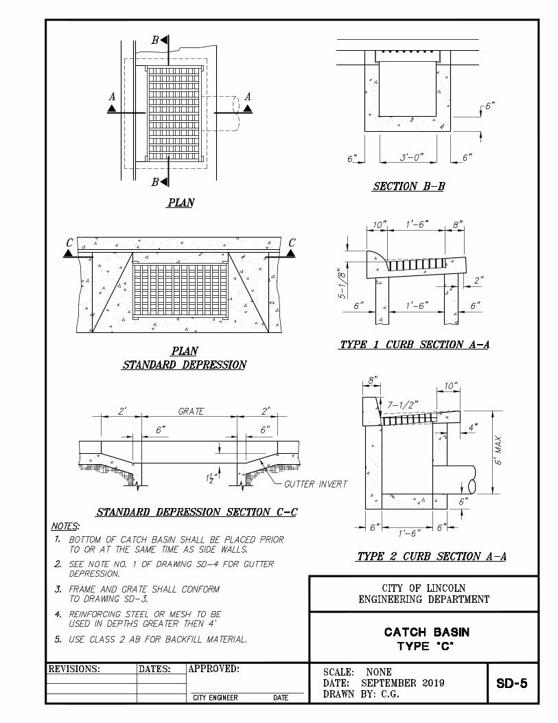
6-4 CATCH BASIN INSTALLATION - Catch basin installations will conform to Standard Details SD-3 through SD-10 and to provisions in Sections 51 and 52 of the Caltrans Standard Specifications. Catch basins located in the right-of-way will be precast concrete or cast-in-place concrete. Catch basins located outside the right-of-way may be PVC, precast concrete, or cast-in-place concrete. The interior of the concrete catch basins will have an ordinary surface finish; rock pockets will be grouted and brushed; exposed top surfaces will have a Class I Surface Finish. The specified PVC surface drainage inlet will be installed using conventional flexible pipe backfill materials and procedures. The backfill material will be Class 2 AB material as defined in ASTM D2321. The surface drainage inlets will be bedded and backfilled uniformly in accordance with ASTM D2321. The drain basin body will be cut at the time of the final grade so as to maintain a one piece, leak proof structure. No brick, stone or concrete block will be used to set the grate to the final grade height. For H-20 Load rated installations, an 8-inch to 10-inch thick concrete ring will be poured under the grate and frame as recommended by details provided from the manufacturer. A. Backfill - Only Caltrans Class 2 Aggregate (AB) Rock will be used as backfill
for a minimum horizontal distance of 2-feet around all catch basins constructed within the City rights-of-way. The Caltrans Class 2 AB Rock will extend vertically upward from the pipe zone to the overlying asphalt concrete (AC) pavement layer. The backfill will be placed and moisture conditioned in maximum 12-inch-thick loose vertical lifts (layers) and then compacted with walk-behind jumping-jack type compactor equipment.
B. Compaction - The backfill will be tested in place to determine its moisture,
density and percent relative compaction using these American Society for Testing and Materials (ASTM) field and laboratory test methods: D1557 (Modified Proctor compaction curve); D2922 (Standard test method for in place density and unit weight of soil and soil-rock mixtures by the Shallow Depth Nuclear Method); D3017 (Standard test method for in place water content of soil and soil-rock mixtures by the Shallow Depth Nuclear Method).
The catch basin backfill will be compacted according to these vertical requirements in the table below:

PUBLIC FACILITES SECTION 6
IMPROVEMENT STANDARDS STORM DRAINAGE
SD 5 of 19
6-5 MANHOLE INSTALLATION
A. Bases
1. Precast - Precast bases will be placed on a foundation of ½- inch minus crushed rock, a minimum of 4-inches thick, compacted to 90% relative compaction. Elevation differentials of inlets and outlets will conform to the approved improvement plans. Openings in the base will align true with all inlet and outlet pipes. Stubs or couplings provided in precast bases will be of the same material as the pipe to which they connect, unless otherwise approved in writing by the City Engineer.
2. Cast-in-Place - The cast-in-place base portion will not be placed higher
than 6-inches above the outside tops of the main incoming and outgoing pipes. Minimum and maximum wall thickness for the cast-in-place sections will conform to this table:
Manhole Diameter Minimum Wall Thickness Maximum Wall Thickness 48-inches 5-inches 7-inches 60-inches 6-inches 8-inches 72-inches 7-inches 9-inches
Inside diameters of cast-in-place base portions will equal the diameter of the manhole specified. Standard precast manhole riser sections and/or cones will be placed above the cast-in-place section to bring the manhole rim to finish grade.
Concrete in the cast-in-place portion will be placed neat against undisturbed earth.
B. Cones - Cone tops will be placed within 6-inches to 18-inches of final street
grade. Where depth is insufficient for cones, flat slab tops will be used. Lifting
Compaction
Pipe Zone Depth of Zone Relative
Compaction Roadway Aggregate
Base Varies 95% Upper Intermediate
Zone 12" Below Aggregate Base 90% Lower Intermediate
Zone 12" below aggregate base to
12" above pipe 90% Pipe Zone 12" above pipe to pipe bottom 90%
Bedding Zone Pipe bottom to 6" below pipe 95%

PUBLIC FACILITES SECTION 6
IMPROVEMENT STANDARDS STORM DRAINAGE
SD 6 of 19
rings in precast cones will be plugged with dry packed mortar.
C. Joints - Joints in precast manhole sections will be made with either mortar or plastic sealing compound.
1. Mortar Application - All joint surfaces and the face of the manhole
base will be thoroughly deemed and wetted before applying mortar. Both the inside and outside of mortared joints will be plastered with mortar and the inside brushed to a smooth finish with a wet brush. Special precautions will be taken to ensure that the entire joint space is filled with mortar and is watertight.
2. Plastic Sealing Compound Application - All joint surfaces and the
face of the manhole base will be thoroughly cleaned before applying plastic sealing compound. The sealing compound will be protected from dirt during application. Ends of the compound will be joined end-to-end and not joined by overlapping. Sufficient compound will be used to cause a visual "squeeze-out" of the compound material when adjacent sections are seated. Squeeze-out material on the inside of the manhole will be neatly trimmed flush with the inside surface.
D. Connections - Pipe connections to drainage manholes will be made so that the
pipe is flush with the inside face of the manhole. These connections will be finished so that entrances are smooth. Unless the manhole is cast around the pipe, connections will be made with dry packed cement mortar. Pipe connections will not be made into the cone section of the manhole unless shown on the approved plans.
E. Grade Rings - Grade adjustments will be made using precast grade rings.
Precast rings will be a minimum of 2-inches in height and a maximum of 12-inches in height.
F. Top of Manhole in Pavement - Frames and covers will be set flush with finish grade, unless otherwise noted on the approved plans. Per the Standard Details, a 12-inch deep by 12-inch wide concrete collar with a #4 rebar ring will be placed around the casting, covered by 2-inches of asphalt concrete paving.
G. Top of Manhole Off-Site - Manholes placed in off-site, unimproved areas will
be constructed with the top of the casting cover a minimum of 12-inches above the final surrounding grade. A minimum 12-inch wide Class "A” concrete collar with a #4 rebar ring will be constructed around the casting and 6-inches below finish grade.
H. Top of Manhole Landscape Area - Manholes placed in landscape areas
adjacent to City improvements will be constructed with the top of the casting cover a minimum of 6-inches above the final surrounding grade. A minimum 12-inch wide Class “A” concrete collar with a #4 rebar ring will be constructed

PUBLIC FACILITES SECTION 6
IMPROVEMENT STANDARDS STORM DRAINAGE
SD 7 of 19
around the casting and 6-inches below finish grade.
I. Adjusting Existing Manhole Frames - The frame will be supported above the grade ring or dome by spacers, or by suspending with timber and wires. After the concrete collar is poured, any space between the frame and grade ring, or dome, will be filled with non-shrink mortar, the inside wall of the riser finished/wet-brushed.
J. Manhole Structure Backfill - These notes and Detail SS-1A apply unless noted otherwise on the approved project improvement plans:
1. Only Caltrans Class 2 Aggregate (AB) Rock will be used as backfill to
a minimum horizontal distance of 5 feet around all manhole structures constructed within the City right-of-ways. The Caltrans Class 2 AB Rock will extend vertically upwards from the pipe zone to the overlying asphalt concrete (AC) pavement layer. Manholes installed at a depth greater than 5-feet will be backfilled with Type “E” Material to a depth of 5-feet below finished grade and to a horizontal distance of 5 feet around the manhole. Backfill between the Type “E” Material and roadway structural section will be Caltrans Class 2 Aggregate Base as described above.
2. The manhole structure backfill will be moisture conditioned to within ± 3 percentage points of the ASTM D1557 optimum moisture content, placed in maximum 12-inch-thick loose vertical lifts (layers), and then compacted with walk behind jumping jack type compactor equipment.
3. The manhole structure trench backfill will be tested in place to determine its moisture, density and percent relative compaction using the following American Society for Testing and Materials (ASTM) field and laboratory test methods: D1557 Modified Proctor compaction curve, D2922 density (nuclear method), D3017 moisture (nuclear method).
4. The manhole structure backfill will be compacted to a minimum relative compaction of 95 percent in the underlying bedding zone, and in the surrounding 5-foot horizontal zone extending from the bedding zone top to the bottom of the overlying AC pavement layer.
6-6 TRENCH WORK - Earthwork required to construct storm drain facilities will be
performed to the lines and grades shown on the approved project improvement plans. At all times, the trench and work area surrounding the trench will be kept in a safe manner to adequately protect the public and the workers. The person designated as the project “superintendent” will be onsite during all work activity. The specified trench width will be maintained to a height of one-foot over the top of the pipe for all trench wall geometry cross-sections including: vertical walls, steeped vertical walls, V-walls, and combined vertical-V-walls.

PUBLIC FACILITES SECTION 6
IMPROVEMENT STANDARDS STORM DRAINAGE
SD 8 of 19
Prior to placing both trench backfill materials and pipes on the trench bottom subgrade surface, the trench bottom will be: relatively free of loose materials, have a relatively smooth appearance, have a relatively constant grade, and be firm and relatively unyielding. The location of cut-off walls shown on the plans may be adjusted in the field if directed by the on-site geotechnical engineer and/or the City Engineer. Refer to detail SD-29 and Section 6-10 of these Public Facilities Improvement Standards Section for additional information on trench materials.
A. Existing Pavement – When the trench is in an existing surfaced area, the pavement will be sawed or scored and broken ahead of the trenching operations. The pavement will be cut accurately on neat and parallel lines. Before the final asphalt concrete patch is placed, the edges of the asphalt concrete will be re-sawcut at least one-foot wider than the width of the trench (“T trench”) to create a smooth parallel edge (see Standard Detail H-25). All cuts in Portland cement concrete pavements will be sawcut with approved equipment.
B. Water in the Trench – When water is encountered in the trench, the
owner’s/developer’s geotechnical consultant will be contacted by the contractor to provide input to the City Engineer. The City requires that a dewatering work plan be prepared and submitted for review prior to implementation in areas where dewatering will be anticipated. The trench will be kept dry in a manner approved by the City Engineer until placement of the approved bedding material, laying and jointing of the pipe, and placement of the shading material has been completed and approved.
The City will consider, on a case-by-case basis, the use of conventional, in-trench, sump-dewatering methods provided that the trench is backfilled with washed, crushed rock or equivalent to at least a height of 3-feet higher than the local ground water table or perched water whichever is at a higher elevation. The crushed rock may require wrapping with a geotextile filter fabric as determined by the owner’s/developer’s geotechnical consultant or required by City Engineer. Installation of ground water monitoring wells can be used to determine the elevation of the water table and/or perched groundwater. The owner’s/developer's geotechnical consultant should develop a dewatering work plan for review and approval by the City Engineer or his/her designated representative prior to implementation. The City requires a dewatering system be designed and implemented in all areas where trenches will be excavated and native backfill will be placed below the local groundwater table and/or perched ground water. Installation of groundwater monitoring wells can be used to determine the elevation of the water table and/or perched groundwater. The dewatering system may include but is not limited to: drive well point screens and
PUBLIC FACILITES SECTION 6
IMPROVEMENT STANDARDS STORM DRAINAGE
SD 9 of 19
vacuum extraction systems, or other dewatering methods. Use of in-trench sumps will not be allowed as the sole dewatering method. The manner employed to dispose of water pumped from an excavation will be subject to the approval of the City Engineer and will conform to all water pollution constraints of the City and other agencies. Groundwater pumped from the trench will be disposed of in a manner to not cause injury to public or private property, or to constitute a nuisance or menace to the public.
C. Unsuitable Trench Bottom - If in the opinion of the owner’s/developer's
geotechnical consultant, or the City Engineer, the bottom of the trench is soft, yielding, or otherwise unsuitable as a foundation for the pipe, the unsuitable material will be removed to the depth necessary to provide a stable and satisfactory foundation. Three-quarter-inch (3/4”) crushed rock will be placed in the trench to provide a stable foundation. The rock is in addition to the required pipe bedding used in the pipe zone. All rock will be wrapped with geotextile fabric (see standard detail SD-29, Type “C” Material).
D. Steel Trench Plates - Steel trench plates will not be used over open trench areas without the approval of the City Engineer. All steel plates will be adequately restrained to eliminate shifting. Trench plates do not eliminate the need for shoring when required. Temporary asphaltic plant mix ("cut-back") at least one-foot in width will be used for a transition on each edge of the plate. “Steel Plate Ahead” signs (W8-24) will be installed 200-feet on each side before the steel plate. The sign will only be mounted to an operable, lighted barricade for a maximum of 24-hours. The sign will be mounted to a 4-inch x 4-inch post if the placement of steel trench plates will exceed 24-hours.
E. Temporary Surfacing - In roadway areas, a temporary asphalt plant mix “cut-
back” surface not less than 2-inches in thickness may be placed immediately after the top backfill has been completed and compacted. This temporary surface will be maintained at a level surface until removal. The temporary surfacing material will be removed just prior to placing the permanent surface material.
F. Open Trench - The trench will be in a safe condition at all times.
1. In roadway areas and locations accessible to the public, trenches will be excavated only as far in advance of pipe laying as can be backfilled in the same day. In addition, the maximum total length of open trench will be no more than 50-feet ahead of the pipe laying operation, or 50-feet behind the pipe laying operation. A trench in an existing roadway that is not to be regraded is defined as "open" until backfilled to existing grade.
2. In new developments and areas not accessible to the public, trenches will be excavated only as far in advance of pipe laying as can be backfilled in the

PUBLIC FACILITES SECTION 6
IMPROVEMENT STANDARDS STORM DRAINAGE
SD 10 of 19
same day. In addition, the maximum total length of open trench will be no more than 300-feet ahead of the pipe laying operation, or 200-feet behind the pipe laying operation. A trench in an existing roadway that is not to be regraded is defined as "open" until backfilled to existing grade.
G. Trench Width - The trench bottom width will be 12-inches to 24-inches greater than the diameter of the pipe and will extend to 24-inches above top of pipe and will comply with Improvement Standard Detail SD-29 or as approved by the City Engineer.
6-7 PIPE BEDDING - Conform to Standard Detail SD-28, SD-29 and the following:
A. Pipe Support - Bedding will provide uniform and continuous support along the barrel of the pipe. The minimum depth of bedding material will be provided under the bell. Blocking of the pipe is not permitted. Loose material will be removed from the trench bottom and replaced with imported material.
B. Saturated Trench - Where a saturated trench condition is encountered, the trench wall and pipe will be lined with a geotextile fabric as shown on Standard Detail SD-29, and to the satisfaction of the City Engineer.
C. Bell Holes - Bell holes will be excavated per the manufacturer’s recommendations. The minimum depth of bedding material will be provided under the bell. Care will be taken to ensure that the bell hole is no larger than necessary to accomplish proper joint assembly.
6-8 CONCRETE CRADLES, ARCHES & ENCASEMENTS - Concrete cradles, arches
and encasements will only be allowed at the discretion of the City Engineer and will conform to the Standard Details and these Improvement Standards:
A. Pipe Support - The pipe will be placed in proper position on temporary supports
consisting of concrete block or bricks. When necessary, the pipe will be rigidly anchored or weighted to prevent flotation when the concrete is placed.
B. Concrete - Concrete for cradles, arches or encasements will be placed uniformly along the pipe. Concrete placed beneath the pipe will be sufficiently workable to fill the voids without excessive vibration. The concrete will be allowed to cure and remain undisturbed for 24-hours prior to backfill and Compaction of the trench. Water will not be permitted to enter, seep, or run onto the concrete while curing.
6-9 PIPE INSTALLATION - Storm drainage pipe will be installed in accordance with
the following provisions:
A. Manufacturers Recommendations – All installations will follow manufacturer's recommendations unless otherwise noted on the approved plans. The manufacturer’s installation guide will be on the job site at all times.

PUBLIC FACILITES SECTION 6
IMPROVEMENT STANDARDS STORM DRAINAGE
SD 11 of 19
B. Pipe Laying Tolerances - The pipes will be laid true to line and grade with
allowed tolerances of 0.03-foot above or below the design grade and 0.10- foot left or right of the design alignment.
C. Placing Pipe - Pipe will be lowered into the trench and carefully placed on the bedding material with the use of lifting equipment and nylon straps. Chains are not permitted. The pipe will be laid carefully to the lines and grades shown without grade breaks, unless designed with such. At the discretion of the City Engineer or his/her representative, any pipe damaged during placement will be removed. If field conditions exist such that the pipe may not be laid to the specified grade, the approved plans will require revisions, approved by the City Engineer, prior to proceeding with construction.
D. Joining Pipe - Pipe sections will be closely jointed to form a smooth flowline. Care will be taken in placing the pipe and making field joints.
E. Covering Pipe - Improvements installed without proper inspection will be exposed and inspected as required by the City Engineer.
F. Reinforced Concrete Pipe - The pipe will be laid up-stream with the bell or groove end of the pipe placed up-stream. The pipe will be gasketed and mortared per manufacturers installation recommendations. The interior of the pipe will be kept clean as the work progresses. For mortared joint precast concrete pipe, the inside of each joint will be wet swabbed with a brush until no mortar protrudes on the inside of the pipe. After mortaring, the exterior of each pipe joint will be covered with a heavy paper membrane for protection. Pipe will not be laid, when, in the opinion of the City Engineer, trench or weather conditions are unsuitable. When excessive grout deposits are suspected in the pipe, a CCTV inspection is required.
G. Laying and Backfill of Polyvinyl Chloride (PVC) and High Density Polyethylene Pipe (HDPE) - Laying and backfill for these pipes will conform to Caltrans Standard Specifications, the manufacturer's recommendations, ASTM D2321 and Standard Detail SD-30, with these modifications:
1. Due to the lightweight characteristic of the pipe, extreme care will be
taken to avoid displacing the pipe during the backfilling operation. Following placement of the pipe on the required bedding and to the required grade, the pipe will be stabilized in place with ballast. At a minimum, this will be accomplished by loading the pipe down slowly and carefully with piles of embedment material to a minimum of one foot above the pipe on each joint and midway on each length. The pipe will be kept centered in the trench during this operation.
2. The trench will then be backfilled with embedment material 6-inches to 12-inches above the pipe, prior to continuing with the trench backfill operations outlined in previous sections.

PUBLIC FACILITES SECTION 6
IMPROVEMENT STANDARDS STORM DRAINAGE
SD 12 of 19
3. Pipe material will not change between manhole structures or between
the last manhole structure and the discharge/inlet opening.
4. The pipe run between the last manhole structure and the discharge/inlet opening will be RCP. Pipe stubs will also be RCP.
5. Pipe Testing - A mandrel test will be conducted following completion of subgrade processing and compaction for curb gutter and sidewalk and asphalt concrete pavement. Placement of curb, gutter and sidewalk and asphalt concrete pavement (and related approved aggregate base) will not occur until the City Engineer has approved the mandrel test. The City Engineer will be present through the duration of the mandrel testing. The allowable deflection (reduction in vertical inside diameter) for all non-rigid pipe will be 7.5% maximum. The deflection will be tested by pulling a mandrel which is 92.5% of the inside pipe diameter through all installed pipe. The mandrel will be the "go/no-go" type and will be pulled per the manufacturer's recommendations without mechanical assistance. Prior to the mandrel test, the pipe will be thoroughly flushed and cleaned. At each location in which the mandrel cannot pass, the cause will be ascertained. Obstacles in the pipe will be removed. If it is determined that the deflection exceeds 7.5%, that a gasket has been mis-installed or that the pipe has been damaged due to trenching for another utility, the respective section of pipe will be re-bedded or removed, replaced and re-bedded using water tight repair couplings. A passing mandrel retest is required. At the contractor's discretion, any sections of non-rigid pipe not passing the mandrel test may be televised to ascertain the problem.
H. Closed Circuit Television Inspections - CCTV inspections will be performed
by the Contractor. Costs for said inspection will be borne by the Contractor. Preliminary inspections may be performed by outside contractors, but will not be accepted by the City Engineer as an official record. The City Engineer, will be notified in writing 72-hours in advance of testing, without exception and will be present during television inspection. Without prior notification, the City reserves the right to reject all final T.V. inspections. The storm drain system will be completely cleaned by an approved method prior to TV inspection. The storm drain system will be rejected if any of these conditions exist: 1. Standing water or sags greater than ½ - inch in depth. 2. Standing water in services. 3. Offset joints. 4. Cracked pipe.
PUBLIC FACILITES SECTION 6
IMPROVEMENT STANDARDS STORM DRAINAGE
SD 13 of 19
5. Infiltration. 6. Protruding laterals.
Refer to the NASSCO Pipeline Assessment Standards for performance standards, including general information and definitions, quality standards, record keeping requirements, digital data formatting, appropriate screen text information and narrations and special CCTV procedures.
6-10 PIPE BACKFILL QA/QC - Pipe backfill will conform to Standard Details SD-28,
SD-29 and these Improvement standards. Construction quality assurance and quality control (QA/QC) of all utility trench backfill will be performed by the owner’s/developer’s geotechnical engineering consultant. A performance-based QA/QC specification will be developed and used for placement and compaction of all non-testable trench backfill materials. A design-based QA/QC specification will be used for placement and compaction of all testable trench backfill material.
A. Performance Based QA/QC (Non-Testable Materials) – Non-testable trench
backfill materials generally consist of locally derived mixtures of cobbles with a sandy matrix and/or breccia (volcanic rock) with a sandy matrix. The non-testable backfill materials should have a maximum particle size of 6-inches (greatest dimension). Use of non-testable trench backfill materials will be approved by the City on a case-by-case basis. A performance-based specification criteria will be used to evaluate the suitability of placed and compacted non-testable trench backfill materials. The property owner’s/developer’s geotechnical engineering consultant must prepare a work plan that describes a proposed site-specific performance-based specification for review and approval by the City prior to commencement of work. The work plan must include, but is not be limited to: 1. Maximum loose lift (layer thickness) prior to compaction.
2. Moisture content range to be achieved prior to compaction.
3. Specified compaction equipment to be used.
4. Minimum number of passes and coverage of specified compaction
equipment.
B. Design Based QA/QC (Testable Materials) – Testable trench backfill materials generally consist of on-site native earth materials and imported earth materials that can be classified as soils according to the American Society for Testing and Materials (ASTM) Unified Soil Classifications System guideline procedures

PUBLIC FACILITES SECTION 6
IMPROVEMENT STANDARDS STORM DRAINAGE
SD 14 of 19
(ASTM D2487 and D2488). These soils materials can be easily tested to determine if they meet the project design based on QA/QC specifications for percent relative compaction by the following ASTM test methods: ASTM D1556, Standard test method for in place density and unit weight of soil and soil-rock mixtures by the Sand-Cone Method. ASTM D2922, Standard test method for in place density and unit weight of soil and soil-rock mixtures by the Shallow Depth Nuclear Method. ASTM D3017, Standard test method for in place water content of soil and soil-rock mixtures by the Shallow Depth Nuclear Method.
C. Trench Backfill Material – The City requires designed based construction QA/QC testing and observation services to be performed by the owner's/developer's geotechnical engineering consultant to document that trench backfills meet or exceed the minimum material properties and minimum relative percent compaction requirements of the City specifications. The general trench backfill material types, and relative percent compaction are presented below. 1. Type “B” Material: Class 2 Aggregate Base Rock per Caltrans Standard
Specifications.
2. Type “C” Material: Material will consist of gravel or crushed rock. Material will be screened and non-washed with a minimum sand equivalent of 30 per CTM217. All material will be free of wood, roots, or other deleterious material. Material to be ½” minus for 12-inch pipe or smaller and ¾” for pipe greater than 12-inches in diameter. Groundwater conditions will require ¾” uniform crushed rock regardless of pipe diameter. Drain rock will be wrapped in a layer of geotextile fabric.
3. Type “D” Material: Crushed rock or soil-rock mixture (native) not to exceed
3 inches. Up to a 6 inch minus material may be used with special considerations and conditions approved by the City and Geotechnical Engineer. The material will be completely free of wood, roots, or other deleterious materials. Material not to be used within 24-inches of top of pipe without City Engineer's approval. Compaction will be by vibratory equipment or other approved devices. The City may require that the material be screened. A layer of geotextile fabric will be placed between the pipes and intermediate backfill zone. Material will only be used with geotechnical engineer’s recommendation and with approval of the City Engineer.
4. Type “E” Material: A low strength, concrete slurry type backfill material made with a mixture of cement, fly-ash, and aggregate. To be used for

PUBLIC FACILITES SECTION 6
IMPROVEMENT STANDARDS STORM DRAINAGE
SD 15 of 19
intermediate zone backfill at depths greater than 5-feet below finished grade. For reference, refer to Section 3-9 “Materials”.
D. Pipe Zone Backfill - For pipe 12-inches in diameter and smaller, no more than
one-half of the pipe will be covered prior to shovel slicing (forcing rock backfill into the lower quadrants of the pipe) For pipe greater than 12-inches in diameter, no more than 6-inches will be covered prior to shovel slicing. At the discretion of the City Engineer or his/her representative, any pipe damaged during backfill will be removed. Shovel slicing will be witnessed by the City Engineer prior to shading the pipe. Proposed bedding, hunching and initial backfill (pipe backfill) materials will be approved by soils engineer and submitted to the City Engineer with sieve analysis and sand equivalent test results. California Test Methods will include 216, 217, 301, and 302. Compaction equipment will not make direct contact with the pipe.
E. Compaction Test Methods - The percent relative compaction of all testable trench backfill soil are determined by a combination of the following ASTM test methods: ASTM D1557, Modified Proctor Compaction Curve.
ASTM D1556, In-place Soil Density by The Sand Cone Replacement
Method.
ASTM D2216, Soil Moisture Content by the Convection Oven Method.
ASTM D2922, In-place Soil Density by Nuclear Method.
ASTM D3017, In-place Soil Moisture Content by Nuclear Method.
ASTM D4643, Soil Moisture Content by the Microwave Oven Method
ASTM D4959, Soil Moisture Content by the Direct Heating Method.
F. Testing Frequencies - All field testable trench backfill materials, that are classified according to the Unified Soils Classification System using ASTM D2487 and D2488 procedures as CL, ML, SC, SM, GC, GM, GP and GW by ASTM tests D422 (Particle Size Gradation) and D4318 (Atterberg Plasticity Indices), will be tested for percent relative compaction using a minimum frequency of one compaction test per maximum 12-inch-thick loose lift (layer) per 250-linear-feet of trench length or material change, whichever condition requires the greatest number of tests. Generally, minimum requirements include 12-inch loose lifts; moisture conditioned to at or above optimum moisture and compacted with 8 to 10 passes/lifts by a sheepsfoot wheel mounted on a Cat 225 or equivalent. At the discretion of the City Engineer, City may require alternative compaction equipment combined with thinner lifts.

PUBLIC FACILITES SECTION 6
IMPROVEMENT STANDARDS STORM DRAINAGE
SD 16 of 19
All field testable trench backfill materials, that are classified according to the Unified Soils Classification system using ASTM D2487 and D2488 procedures as CL, CH, ML and MH by ASTM tests D422 (Particle Size Gradation) and D4318 (Atterberg Plasticity Indices), should be tested for percent relative compaction using a minimum frequency of one compaction test per maximum 12-inch-thick loose lift (layer) per 100-linear-feet of trench length or material change, which ever condition requires the greatest number of tests.
G. Warning Tape - A 12-inch wide metallic backfill tape with the warning "Buried Storm Drain” will be placed in the trench lines of all mains and services, 24- inches above the top of pipe within road areas and 18” above the top of pipe within non-road areas.
H. Markings in Unpaved Areas - Mains in unpaved areas will be marked every 125 lineal feet with a green composite utility marker with a decal stating "Caution Buried Storm Drain". Mains in landscaped areas will be delineated with a brass marker set in an 8-inch diameter concrete cylinder. The brass marker will state “City of Lincoln Storm Drain”.
6-11 MATERIALS
A. Backfill Material - All drain pipe backfill material will conform to Standard Detail
SD-29.
B. Catch Basins - All catch basins will conform to Standard Details SD-3 to SD-10. Concrete to be Class "A", reinforcing steel to conform to provisions in Section 52 of the Caltrans Standard Specifications.
C. Alternative PVC Catch Basins - Th drain basins required will be manufactured from PVC pipe stock, utilizing a thermo-molding process to reform the pipe stock to the specified configuration. The drainage pipe connection stubs will be manufactured from PVC pipe stock and formed to provide a watertight connection with the specified pipe system. This joint tightness will conform to ASTM D3212 for joints for drain plastic pipe using flexible elastomeric seals. The pipe bell spigot will be joined to the main body of the drain basin or catch basin. The pipe stock used to manufacture the main body and pipe stubs of the surface drainage inlets will meet the mechanical property requirements for fabricated fittings as described by ASTM D3034. The grates furnished for all surface drainage inlets will be ductile iron grates for sizes 8-inch, 10-inch, 12-inch, 15-inch, 18-inch, 24-inch and 30-inch (12-inch and 15-inch frames are cast iron) will be made specifically for each basin so as to provide a round bottom flange that closely matches the diameter of the surface drainage inlet. Grates for drain basins will be capable of supporting H-20 wheel loading for heavy-duty traffic or H-10 loading for pedestrian traffic. 12-inch and 15-inch grates will be hinged to the frame using pins. Metal used in the manufacture of the castings will conform to ASTM A536 grade 70-50-05 for ductile iron and

PUBLIC FACILITES SECTION 6
IMPROVEMENT STANDARDS STORM DRAINAGE
SD 17 of 19
ASTM A-48-83 class 30B for 12-inch and 15-inch cast iron frames. Grates will be provide painted black.
D. Lined Channels - All lined channels shall conform to Standard Details SD-18 and SD-19 and these materials:
1. Air Blown Mortar - Air blown mortar will conform to provisions in Section
53 of the Caltrans Standard Specifications. 2. Concrete- Concrete will be either Class A "6-sack" concrete with Type II
cement, sacked concrete, or doweled and sacked concrete. The minimum weight of sacked concrete will be 60 pounds per sack.
3. Curing Compound - Curing Compound will conform to provisions in Section
90 of the Caltrans Special Provisions. 4. Expansion Joint Filler – Pre-molded expansion joint fillers will be a
minimum of 3/8-inch thick and conform to ASTM Designation D1751. 5. Grouted Cobbles - Grouted cobbles will require Class A "6 sack" concrete
with the cobble mixture to be: all retained on the 1-1/2-inch sieve; not more than 40% passing the 4-inch sieve; and 10-inch maximum size.
6. Weep Holes - All weep holes will be 2-inches in diameter and made of:
galvanized steel pipe, Schedule 40 or better; PVC pipe, Schedule 40 or better; or, ASS pipe, Schedule 40 or better.
7. Welded Wire Fabric - Welded wire fabric to conform to ASTM Designation
A185.
E. Manholes - All precast manhole barrels, risers, cones, flat tops and grade rings will conform to ASTM Designation C478 and will conform to dimensions shown on Standard Detail SD-23.
1. Bases - Bases will be either precast or cast-in-place. Precast bases will
conform to ASTM Designation C478. Cast-in-place bases will be Class A "6-sack" concrete with Type II cement. Slump will not exceed 4- inches as determined by the slump cone method of ASTM Designation C143 or an equivalent slump as determined by CTM 533.
2. Cones - All cones will conform to ASTM Designation C478. 3. Joints - Joints will be made with either non-shrinking mortar or with plastic
sealing compounds conforming to Federal Specifications SS-S-00210. 4. Manhole Frames and Covers - All castings for manhole frame castings,
covers and other purposes will be of cast iron and conform to ASTM Designation A48, Class 30 and will conform to dimensions shown on

PUBLIC FACILITES SECTION 6
IMPROVEMENT STANDARDS STORM DRAINAGE
SD 18 of 19
Standard Detail SD-22. 5. Mortar - Mortar used in finishing manholes and joints will be non-shrinking
and consist of 1-cubic-foot of Portland Cement to 2-cubic-feet of concrete sand.
6. Pipe Connections - Pipe connections for precast concrete tongue and
groove pipe will be made using mortar that will be non-shrinking and consist of 1-cubic-foot of Portland Cement to 2-cubic-feet of concrete sand.
F. Outlet and Inlet Structures- All outlet structures will conform to Standard
Details SD-15 to SD-17.
G. Slurry Cement Backfill – Slurry cement backfill will conform to the requirements of Section 19 of the Caltrans Standard Specifications.
H. Storm Drain Pipe – Storm drain pipe will conform to the following:
1. Acrylonitrile-Butadiene-Styrene (ABS) – ABS pipe will meet the requirements of ASTM Designation D2680.
2. High Density Polyethylene Pipe (HDPE) - HDPE will be Type "S",
conforming to Section 64 of the Caltrans Standard Specifications. Joint connections will be watertight. A listing of approved manufacturers includes ADS, Inc., Hancor or approved equal.
Pipe will meet the requirements of AASHTO Specifications M-294. Pipe will be type S. Pipe and resin producers will be certified according to the PPI/CPPA Third Party Certification Program. All corrugated polyethylene pipe will contain the appropriate program mark, either an official label or permanent affixation prior to shipment. Pipe joints will conform to one of these performance criteria:
a. Soil tight joints as defined by AASHTO Standard Specifications for
Highway Bridges, Division II, Section 26. b. Soil tight joints must meet a 2-psi (14 kPa) laboratory test per modified
ASTM D3212 and utilize a bell and spigot design with a gasket meeting ASTM F477.
c. Watertight joints must meet a 10.8-psi (74 kPa) laboratory test per ASTM D3212 and utilize a bell and spigot design with a gasket meeting ASTM F477.
Fittings used with the pipe will not reduce or impair the overall integrity or function of the pipeline. Fittings may be molded or fabricated and will be furnished by the pipe manufacturer.

PUBLIC FACILITES SECTION 6
IMPROVEMENT STANDARDS STORM DRAINAGE
SD 19 of 19
The manufacturer will provide, when required, a suitable repair coupling certified to provide a watertight seal to 3.5 psi.
3. Polyvinyl Chloride Pipe (PVC) - PVC will conform to the following
standards based on pipe diameter: Pipe Diameter ASTM Designation
10-inch through 15-inch D3034, SDR 35 18-inch through 27-inch F794, F2241, SDR 51 30-inch through 48-inch F794 All PVC pipe joints will be integral wall bell and spigot configuration, factory formed. All rubber rings will conform to ASTM Designation F477.
4. Precast Reinforced Concrete Pipe (RCP) - RCP will conform to ASTM
Designation C76 for Class I, II, Ill, IV or V. The class of pipe will be based on the designation conforming to the approved plans. Joints for RCP will be tongue and groove, bell and spigot, or other approved type, and will be of such a design that when properly laid, they will have a smooth and uniform interior surface. Each joint will be sealed to prevent leakage. Sealing materials will consist of rubber gasketed joints or resilient materials conforming to Section 65 of the Caltrans Standard Specifications.
5. Alternate Pipe Materials - Alternate pipe materials such as spiral ribbed aluminum coated steel, or other materials, may be submitted with soils analysis and other technical data, for approval by the City Engineer.

PUBLIC FACILITIES IMPROVEMENT STANDARDS
[THIS PAGE INTENTIONALLY LEFT BLANK]
PUBLIC FACILITES
IMPROVEMENT STANDARDS
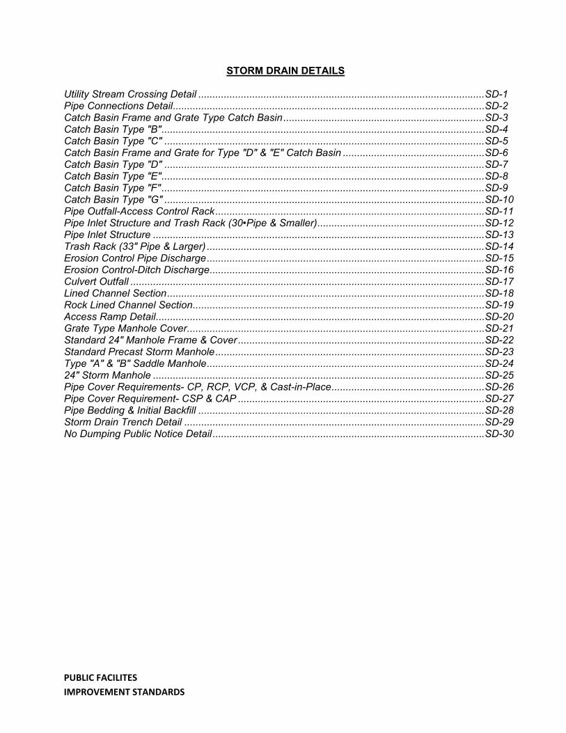
STORM DRAIN DETAILS
Utility Stream Crossing Detail ..................................................................................................... SD-1 Pipe Connections Detail .............................................................................................................. SD-2 Catch Basin Frame and Grate Type Catch Basin ....................................................................... SD-3 Catch Basin Type "B" .................................................................................................................. SD-4 Catch Basin Type "C" ................................................................................................................. SD-5 Catch Basin Frame and Grate for Type "D" & "E" Catch Basin .................................................. SD-6 Catch Basin Type "D" ................................................................................................................. SD-7 Catch Basin Type "E" .................................................................................................................. SD-8 Catch Basin Type "F" .................................................................................................................. SD-9 Catch Basin Type "G" ................................................................................................................. SD-10 Pipe Outfall-Access Control Rack ............................................................................................... SD-11 Pipe Inlet Structure and Trash Rack (30•Pipe & Smaller) ........................................................... SD-12 Pipe Inlet Structure ..................................................................................................................... SD-13 Trash Rack (33" Pipe & Larger) .................................................................................................. SD-14 Erosion Control Pipe Discharge .................................................................................................. SD-15 Erosion Control-Ditch Discharge ................................................................................................. SD-16 Culvert Outfall ............................................................................................................................. SD-17 Lined Channel Section ................................................................................................................ SD-18 Rock Lined Channel Section ....................................................................................................... SD-19 Access Ramp Detail .................................................................................................................... SD-20 Grate Type Manhole Cover ......................................................................................................... SD-21 Standard 24" Manhole Frame & Cover ....................................................................................... SD-22 Standard Precast Storm Manhole ............................................................................................... SD-23 Type "A" & "B" Saddle Manhole .................................................................................................. SD-24 24" Storm Manhole ..................................................................................................................... SD-25 Pipe Cover Requirements- CP, RCP, VCP, & Cast-in-Place ...................................................... SD-26 Pipe Cover Requirement- CSP & CAP ....................................................................................... SD-27 Pipe Bedding & Initial Backfill ..................................................................................................... SD-28 Storm Drain Trench Detail .......................................................................................................... SD-29 No Dumping Public Notice Detail ................................................................................................ SD-30

PUBLIC FACILITIES IMPROVEMENT STANDARDS
[THIS PAGE INTENTIONALLY LEFT BLANK]


PUBLIC FACILITIES IMPROVEMENT STANDARDS
[THIS PAGE INTENTIONALLY LEFT BLANK]