chapter 2 hydrostatics and control - · pdf fileship stability and hydrostatics. chapter 2...
TRANSCRIPT

5
Abstract A submarine must conform to Archimedes’ Principle, which states that a body immersed in a fluid has an upward force on it (buoyancy) equal to the weight of the displaced fluid, (displacement). There are two different definitions of submerged displacement: one that doesn’t include the mass of fluid in the free flooding spaces (hydrostatic displacement), which is used by submarine naval architects, and one that does include the mass of the fluid in the free flooding spaces (form displacement), which is used by submarine hydrodynamicists. For equilibrium in the vertical plane the mass must be balanced exactly by the buoyancy force. As compressibility affects the buoyancy, it is not possible for a submarine to be in stable equilibrium in the ver-tical plane. Ballast tanks fit into two categories: those used for major adjustment of mass (main ballast tanks); and those used for minor adjustments (trim tanks). The effect of each tank is plotted and this is compared with the changes in mass and trim-ming moment possible during operations using a trim polygon to determine whether the ballast tanks are adequate. Transverse stability of a submarine is discussed, includ-ing particular issues that arise when passing through the free surface, when on the sea-bed, or when surfacing through ice. On the water surface, metacentric height (GM) is important, whereas below the surface it is the distance between the centre of buoyancy and the centre of gravity (BG) which governs the transverse stability of a submarine.
Keywords Hydrostatic displacement · Form displacement · Compressibility · Ballast tanks · Transverse stability · Trim polygon
2.1 Hydrostatics and Displacement
As with any object in a fluid, a submarine must conform to Archimedes’ Principle, which states that a body immersed in a fluid has an upward force on it (buoyancy) equal to the weight of the displaced fluid, (displacement). This applies whether the submarine is floating on the water surface, or deeply submerged. Readers are referred to texts such as Rawson and Tupper (2001) for general information about ship stability and hydrostatics.
Chapter 2Hydrostatics and Control
© The Author(s) 2015 M. Renilson, Submarine Hydrodynamics, SpringerBriefs in Applied Sciences and Technology, DOI 10.1007/978-3-319-16184-6_2
6 2 Hydrostatics and Control
When it is floating on the water surface, less of the boat is under the water, and hence the buoyancy and the displacement will be less than when it is submerged.
A key feature of a submarine is its ability to vary its mass, and hence to change from floating on the water surface, to being fully submerged, and vice versa. Therefore, a submarine will have a submerged displacement, for when it is operating under the surface, and a surface displacement for operations on the water surface. It is quite normal to have more than one surfaced displacement, depending on the level of reserve buoyancy required for any given operation. This principle is exactly the same as that for a conventional vessel, which may operate at more than one draught.
In addition, there are two different definitions of submerged displacement as given in Table 2.1.
Hydrostatic displacement is usually used by naval architects when considering the mass and buoyancy balance of the submarine, particularly at the design stage. The free flood water, such as that in the main ballast tanks and under casings, is excluded, as this can be considered to be irrelevant to either the total mass of the vessel, or its total buoyancy.
On the other hand, the form displacement is usually used by hydrodynamicists, who are concerned with the mass of the submarine which needs to be propelled, and manoeuvred. In this case, as the mass of the water in the main ballast tanks and under casings needs to move with the submarine, it is necessary that it be considered.
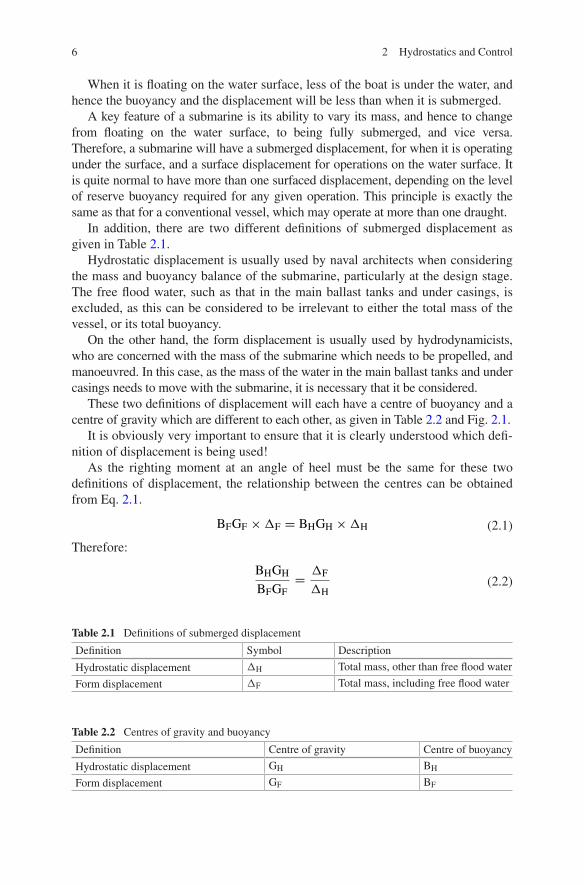
These two definitions of displacement will each have a centre of buoyancy and a centre of gravity which are different to each other, as given in Table 2.2 and Fig. 2.1.
It is obviously very important to ensure that it is clearly understood which defi-nition of displacement is being used!
As the righting moment at an angle of heel must be the same for these two definitions of displacement, the relationship between the centres can be obtained from Eq. 2.1.
Therefore:
(2.1)BFGF �F = BHGH �H
(2.2)BHGH
BFGF
=�F
�H
Table 2.1 Definitions of submerged displacement
Definition Symbol Description
Hydrostatic displacement ΔH Total mass, other than free flood water
Form displacement ΔF Total mass, including free flood water
Table 2.2 Centres of gravity and buoyancy
Definition Centre of gravity Centre of buoyancy
Hydrostatic displacement GH BH
Form displacement GF BF
7
2.2 Static Control
2.2.1 Control in the Vertical Plane
The downward force due to the mass multiplied by gravity must be balanced by the upward buoyancy force given by the immersed volume multiplied by the water density and gravity.
Unlike for a surface ship, in the case of a deeply submerged submarine the immersed volume cannot be increased by increasing the vessel’s draught. Thus, for equilibrium in the vertical plane the mass must be balanced exactly by the buoyancy force. Clearly this is difficult, if not impossible to achieve.
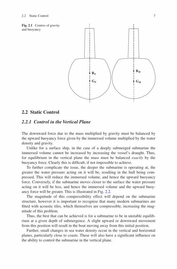
To further complicate the issue, the deeper the submarine is operating at, the greater the water pressure acting on it will be, resulting in the hull being com-pressed. This will reduce the immersed volume, and hence the upward buoyancy force. Conversely, if the submarine moves closer to the surface the water pressure acting on it will be less, and hence the immersed volume and the upward buoy-ancy force will be greater. This is illustrated in Fig. 2.2.
The magnitude of this compressibility effect will depend on the submarine structure, however it is important to recognise that many modern submarines are fitted with acoustic tiles, which themselves are compressible, increasing the mag-nitude of this problem.
Thus, the best that can be achieved is for a submarine to be in unstable equilib-rium at a given depth of submergence. A slight upward or downward movement from this position will result in the boat moving away from this initial position.
Further, small changes in sea water density occur in the vertical and horizontal planes, particularly close to coasts. These will also have a significant influence on the ability to control the submarine in the vertical plane.
Fig. 2.1 Centres of gravity and buoyancy
BF
GF
BH
GH
2.2 Static Control
8 2 Hydrostatics and Control
In addition, the mass on board will change during a voyage due to use of consumables and discharge of weapons.
Hence, it is necessary to have the ability to make small changes in mass of the boat very quickly, which is done by a series of ballast tanks, as discussed in Sect. 2.3. Even then, it is very difficult to control a submarine in the vertical plane at zero forward speed, and so it is necessary to make use of hydrodynamic forces, as discussed in Chap. 3.
2.2.2 Transverse Stability
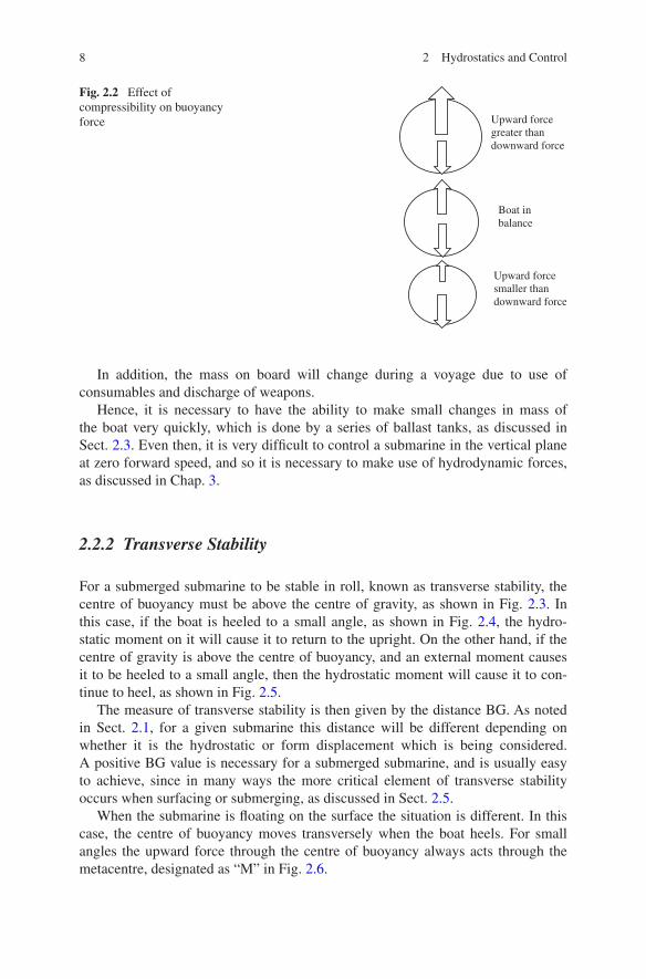
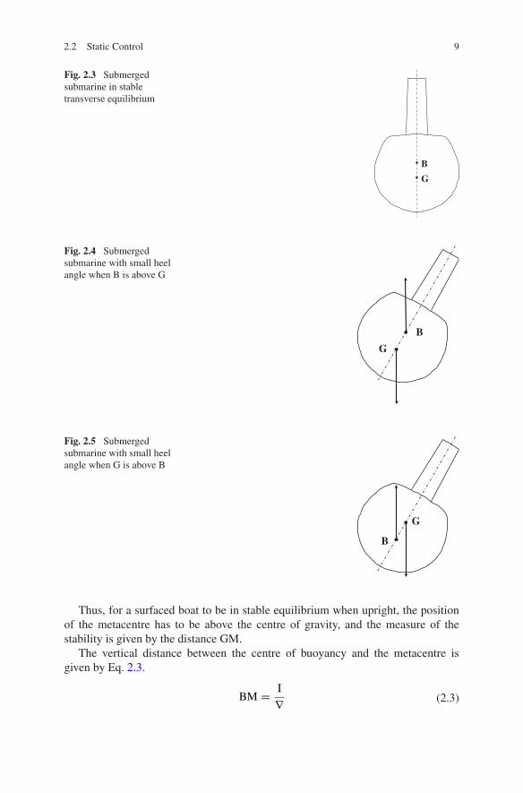
For a submerged submarine to be stable in roll, known as transverse stability, the centre of buoyancy must be above the centre of gravity, as shown in Fig. 2.3. In this case, if the boat is heeled to a small angle, as shown in Fig. 2.4, the hydro-static moment on it will cause it to return to the upright. On the other hand, if the centre of gravity is above the centre of buoyancy, and an external moment causes it to be heeled to a small angle, then the hydrostatic moment will cause it to con-tinue to heel, as shown in Fig. 2.5.
The measure of transverse stability is then given by the distance BG. As noted in Sect. 2.1, for a given submarine this distance will be different depending on whether it is the hydrostatic or form displacement which is being considered. A positive BG value is necessary for a submerged submarine, and is usually easy to achieve, since in many ways the more critical element of transverse stability occurs when surfacing or submerging, as discussed in Sect. 2.5.
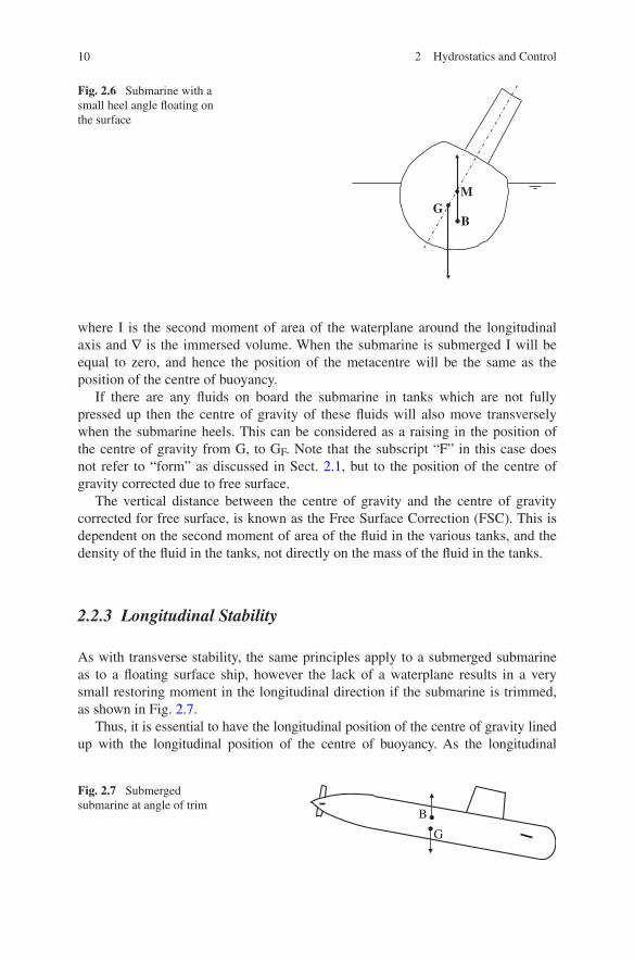
When the submarine is floating on the surface the situation is different. In this case, the centre of buoyancy moves transversely when the boat heels. For small angles the upward force through the centre of buoyancy always acts through the metacentre, designated as “M” in Fig. 2.6.
Fig. 2.2 Effect of compressibility on buoyancy force
Boat in balance
Upward force greater than downward force
Upward force smaller than downward force
9
Thus, for a surfaced boat to be in stable equilibrium when upright, the position of the metacentre has to be above the centre of gravity, and the measure of the stability is given by the distance GM.
The vertical distance between the centre of buoyancy and the metacentre is given by Eq. 2.3.
(2.3)BM =I
∇
Fig. 2.3 Submerged submarine in stable transverse equilibrium
B
G
Fig. 2.4 Submerged submarine with small heel angle when B is above G
B
G
Fig. 2.5 Submerged submarine with small heel angle when G is above B
B
G
2.2 Static Control
10 2 Hydrostatics and Control
where I is the second moment of area of the waterplane around the longitudinal axis and ∇ is the immersed volume. When the submarine is submerged I will be equal to zero, and hence the position of the metacentre will be the same as the position of the centre of buoyancy.
If there are any fluids on board the submarine in tanks which are not fully pressed up then the centre of gravity of these fluids will also move transversely when the submarine heels. This can be considered as a raising in the position of the centre of gravity from G, to GF. Note that the subscript “F” in this case does not refer to “form” as discussed in Sect. 2.1, but to the position of the centre of gravity corrected due to free surface.
The vertical distance between the centre of gravity and the centre of gravity corrected for free surface, is known as the Free Surface Correction (FSC). This is dependent on the second moment of area of the fluid in the various tanks, and the density of the fluid in the tanks, not directly on the mass of the fluid in the tanks.
2.2.3 Longitudinal Stability
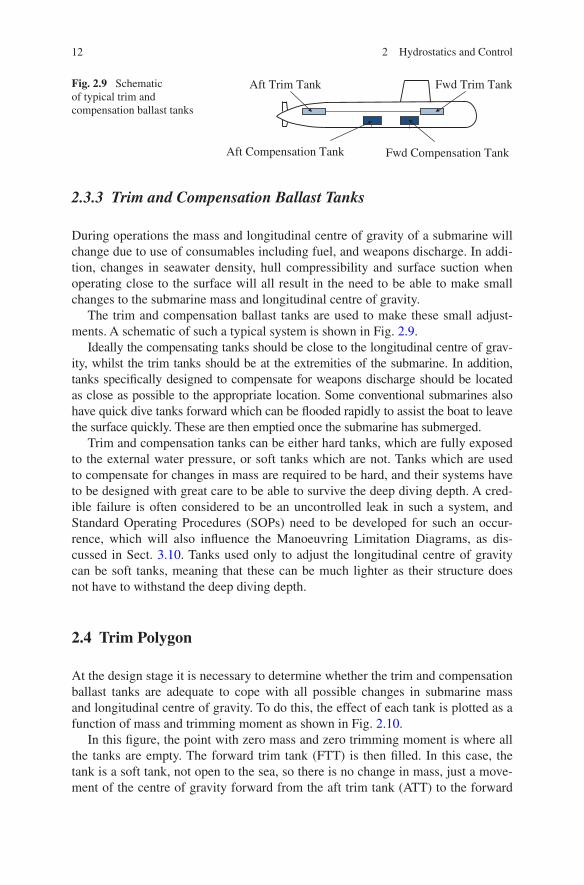
As with transverse stability, the same principles apply to a submerged submarine as to a floating surface ship, however the lack of a waterplane results in a very small restoring moment in the longitudinal direction if the submarine is trimmed, as shown in Fig. 2.7.
Thus, it is essential to have the longitudinal position of the centre of gravity lined up with the longitudinal position of the centre of buoyancy. As the longitudinal
Fig. 2.6 Submarine with a small heel angle floating on the surface
BG
M
Fig. 2.7 Submerged submarine at angle of trim
B
G

11
position of the centre of gravity moves during a voyage due to use of consumables, firing of weapons, etc., it is necessary to be able to adjust this by use of ballast tanks, as discussed in Sect. 2.3.
2.3 Ballast Tanks
2.3.1 Categories of Ballast Tanks
Ballast tanks fit into two different categories:
(a) those used for major adjustment of submarine mass to allow it to operate submerged as well as on the surface (main ballast tanks); and
(b) those used for minor adjustments to keep the submarine balanced when submerged (trim and compensation system).
2.3.2 Main Ballast Tanks
The Main Ballast Tanks (MBTs), are usually ballast tanks external to the pres-sure hull, which are free flooding when the submarine is submerged, as shown in Fig. 2.8.
The purpose of the MBTs is to allow major adjustment of the submarine mass to enable it to operate submerged as well as on the water surface. Water and air enter and leave the MBTs through flooding holes at the bottom and vents at the top of the tanks.
When the submarine is on the water surface the MBTs are flooded by opening the vent valves, allowing water to enter the MBTs through the flooding holes. The size of the vents and the flooding holes will have a direct effect on the length of time that it takes for the MBTs to fill, and hence on how long it will take for the submarine to submerge. Ideally the size should be chosen such that all the tanks flood at the same time. The size of the flooding holes will also affect the hydro-acoustic signature when the submarine is operating submerged, as they cause a disturbance to the flow around them. Small flooding holes may cause problems with over-pressure, and stability issues on the surface.
Fig. 2.8 Schematic of typical Main Ballast Tank system
Pressure hullAft MBT
Fwd MBT
Vents (air out)
Flooding holes (water in & out)
2.2 Static Control
12 2 Hydrostatics and Control
2.3.3 Trim and Compensation Ballast Tanks
During operations the mass and longitudinal centre of gravity of a submarine will change due to use of consumables including fuel, and weapons discharge. In addi-tion, changes in seawater density, hull compressibility and surface suction when operating close to the surface will all result in the need to be able to make small changes to the submarine mass and longitudinal centre of gravity.
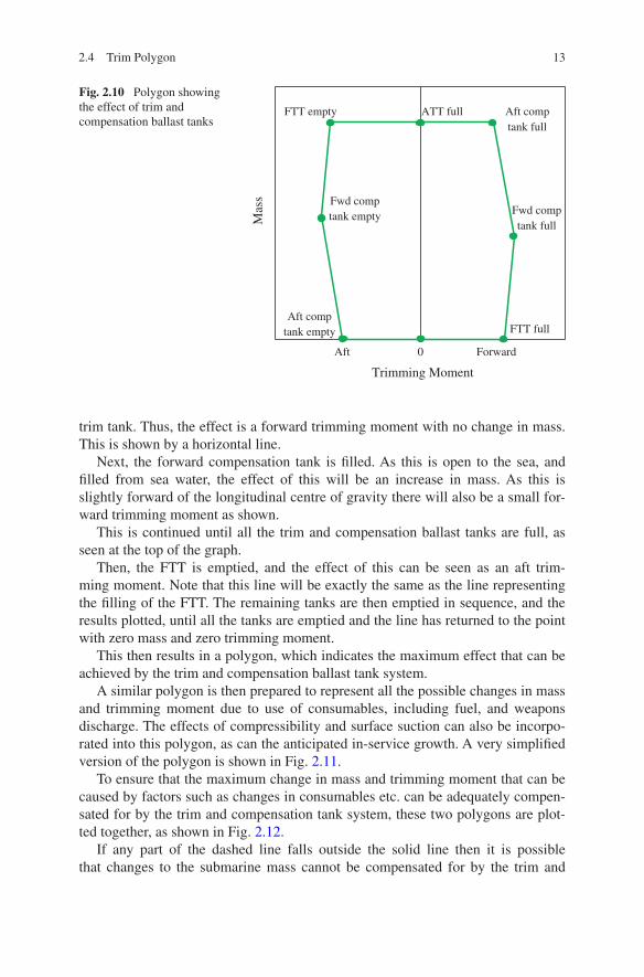
The trim and compensation ballast tanks are used to make these small adjust-ments. A schematic of such a typical system is shown in Fig. 2.9.
Ideally the compensating tanks should be close to the longitudinal centre of grav-ity, whilst the trim tanks should be at the extremities of the submarine. In addition, tanks specifically designed to compensate for weapons discharge should be located as close as possible to the appropriate location. Some conventional submarines also have quick dive tanks forward which can be flooded rapidly to assist the boat to leave the surface quickly. These are then emptied once the submarine has submerged.
Trim and compensation tanks can be either hard tanks, which are fully exposed to the external water pressure, or soft tanks which are not. Tanks which are used to compensate for changes in mass are required to be hard, and their systems have to be designed with great care to be able to survive the deep diving depth. A cred-ible failure is often considered to be an uncontrolled leak in such a system, and Standard Operating Procedures (SOPs) need to be developed for such an occur-rence, which will also influence the Manoeuvring Limitation Diagrams, as dis-cussed in Sect. 3.10. Tanks used only to adjust the longitudinal centre of gravity can be soft tanks, meaning that these can be much lighter as their structure does not have to withstand the deep diving depth.
2.4 Trim Polygon
At the design stage it is necessary to determine whether the trim and compensation ballast tanks are adequate to cope with all possible changes in submarine mass and longitudinal centre of gravity. To do this, the effect of each tank is plotted as a function of mass and trimming moment as shown in Fig. 2.10.
In this figure, the point with zero mass and zero trimming moment is where all the tanks are empty. The forward trim tank (FTT) is then filled. In this case, the tank is a soft tank, not open to the sea, so there is no change in mass, just a move-ment of the centre of gravity forward from the aft trim tank (ATT) to the forward
Fig. 2.9 Schematic of typical trim and compensation ballast tanks
Aft Trim Tank Fwd Trim Tank
Aft Compensation Tank Fwd Compensation Tank
13
trim tank. Thus, the effect is a forward trimming moment with no change in mass. This is shown by a horizontal line.
Next, the forward compensation tank is filled. As this is open to the sea, and filled from sea water, the effect of this will be an increase in mass. As this is slightly forward of the longitudinal centre of gravity there will also be a small for-ward trimming moment as shown.
This is continued until all the trim and compensation ballast tanks are full, as seen at the top of the graph.
Then, the FTT is emptied, and the effect of this can be seen as an aft trim-ming moment. Note that this line will be exactly the same as the line representing the filling of the FTT. The remaining tanks are then emptied in sequence, and the results plotted, until all the tanks are emptied and the line has returned to the point with zero mass and zero trimming moment.
This then results in a polygon, which indicates the maximum effect that can be achieved by the trim and compensation ballast tank system.
A similar polygon is then prepared to represent all the possible changes in mass and trimming moment due to use of consumables, including fuel, and weapons discharge. The effects of compressibility and surface suction can also be incorpo-rated into this polygon, as can the anticipated in-service growth. A very simplified version of the polygon is shown in Fig. 2.11.
To ensure that the maximum change in mass and trimming moment that can be caused by factors such as changes in consumables etc. can be adequately compen-sated for by the trim and compensation tank system, these two polygons are plot-ted together, as shown in Fig. 2.12.
If any part of the dashed line falls outside the solid line then it is possible that changes to the submarine mass cannot be compensated for by the trim and
Fig. 2.10 Polygon showing the effect of trim and compensation ballast tanks
Trimming Moment
Mas
s
0 ForwardAft
FTT full
Fwd comptank full
Aft comptank full
ATT fullFTT empty
Fwd comptank empty
Aft comptank empty
2.4 Trim Polygon

14 2 Hydrostatics and Control
compensation tank system. This then demonstrates that the trim and compensation tank system is not adequate, and hence modifications are required. In Fig. 2.12 there is sufficient margin between the effect possible using the trim and compensa-tion ballast system, and the maximum anticipated changes in submarine mass and trim, so the trim and compensation system is adequate.
2.5 Stability When Surfacing/Diving
As discussed in sub Sect. 2.2.2, when a submarine is submerged, transverse stabil-ity is achieved if the centre of buoyancy is above the centre of gravity, and this distance, BG, is a measure of the boat’s stability. When the submarine is floating on
Fig. 2.11 Polygon showing the effect of changes in mass
Trimming MomentM
ass
0 ForwardAft
Fig. 2.12 Schematic of trim polygon
Mas
s
Trimming Moment
Aft 0 Forward

15
the water surface the centre of buoyancy moves transversely as a function of heel angle. For small angles this acts through the metacentre, M. Thus, the measure of stability is then the distance that the metacentre is above the centre of gravity, GM.
As a submarine transitions from floating on the water surface to fully sub-merged its vertical centres of both buoyancy and gravity will vary, due to a change in immersion of the hull, and the change in mass in the ballast tanks. In addition, the second moment of the waterplane, I, will vary during this process. This will also significantly affect the position of the metacentre, M, Eq. 2.3.
To ensure that a submarine remains stable as it is transiting from being on the sur-face to fully submerged, a plot of the positions of the various centres is made as a function of draught. An example of this is given in Fig. 2.13. The values of KB, BM, KM, and KGF (KG corrected for free surface) are given as functions of draught. In this case the lightest surface draught is 4.5 m. The casing is fully submerged at a draught of approximately 5.5 m, and the submarine is fully submerged at a draught of 7 m.
As can be seen, in this case the surface GFM value is positive, the minimum value of BGF is positive, and the fully submerged value of BGF is positive.
An additional complexity, not shown directly in Fig. 2.13, is that, when sur-facing, water is retained in the casing, and other free flood spaces, for a period before it can escape. This will raise the centre of gravity above that assumed for the steady state calculations used to generate Fig. 2.13. The length of time that this water takes to escape will depend on the size of the free flooding holes, however as noted in sub Sect. 2.3.2 large holes may affect the hydro-acoustic noise gener-ated when submerged.
Fig. 2.13 Curve of stability when passing through free surface
2.5 Stability When Surfacing/Diving
16 2 Hydrostatics and Control
2.6 Stability When Bottoming
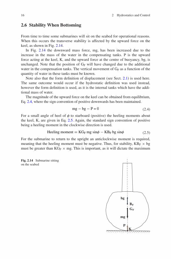
From time to time some submarines will sit on the seabed for operational reasons. When this occurs the transverse stability is affected by the upward force on the keel, as shown in Fig. 2.14.
In Fig. 2.14 the downward mass force, mg, has been increased due to the increase in the mass of the water in the compensating tanks. P is the upward force acting at the keel, K, and the upward force at the centre of buoyancy, bg, is unchanged. Note that the position of GF will have changed due to the additional water in the compensation tanks. The vertical movement of GF as a function of the quantity of water in these tanks must be known.
Note also that the form definition of displacement (see Sect. 2.1) is used here. The same outcome would occur if the hydrostatic definition was used instead, however the form definition is used, as it is the internal tanks which have the addi-tional mass of water.
The magnitude of the upward force on the keel can be obtained from equilibrium, Eq. 2.4, where the sign convention of positive downwards has been maintained.
For a small angle of heel of φ to starboard (positive) the heeling moments about the keel, K, are given in Eq. 2.5. Again, the standard sign convention of positive being a heeling moment in the clockwise direction is used.
For the submarine to return to the upright an anticlockwise moment is required, meaning that the heeling moment must be negative. Thus, for stability, KBF × bg must be greater than KGF × mg. This is important, as it will dictate the maximum
(2.4)mg− bg− P = 0
(2.5)Heeling moment = KGF mg sinφ − KBF bg sinφ
Fig. 2.14 Submarine sitting on the seabed
BF
GF
KP
mg
bg

17
amount of water that can be added to the compensating tanks whilst remaining stable. If these are located low in the boat, then there may not be a limit to the amount of water without affecting stability, however if these are high, then it may be necessary to set a limit of the amount of water in the compensating tanks in this condition, to maintain transverse stability.
2.7 Stability When Surfacing Through Ice
Submarines operating under ice must be able to surface by breaking through the ice. The normal procedure is to stop the submarine under thin ice, and then to slowly surface at zero forward speed.
When the sail first makes contact with the ice there will be a downward force from the ice, P, which will increase as ballast is removed, and buoyancy increased, until the ice breaks. This will influence the stability of the submarine, as shown in Fig. 2.15.
The analysis is analogous to the case when the submarine is sitting on the sea-bed, as discussed in Sect. 2.6, and the maximum force which can be applied can be obtained in a similar manner. The initial value of BG must be sufficiently high to allow for the reduction in stability caused by the force at the top of the sail required to break through the ice.
Reference
Rawson KJ, Tupper EC (2001) Basic ship theory, 5th edn. Butterworth-Heinemann, Boston
Fig. 2.15 Submarine breaking through ice
BF
GF
K
mg
bg
P
2.6 Stability When Bottoming

http://www.springer.com/978-3-319-16183-9