chapter 1 introduction - stanford universityyuba.stanford.edu/~sd2/ch_1.pdf · 2 chapter 1....
TRANSCRIPT
1
Chapter 1
Introduction
Large scale networks are expensive to operate and service providers are always looking
for ways to reduce their capital and operational costs. One approach involves reducing
the number of different types of networks they own. This can be accomplished by
converging the different services the networks offer on to one network. For example,
many service providers have eliminated specialized core-telephony networks and
converged voice services with data services on to IP networks.
This thesis however, is about the convergence of networks running at two layers.
Large service providers such as AT&T and Verizon support two infrastructures – a Layer
3 IP network and an underlying Layer 1/0 optical transport network. Today these
networks are run separately; they are planned, designed and operated by different groups
of people, even if they are in the same organization.
Partly this separation is because of the different heritage of the two networks.
Transport networks – with their telecom heritage – tend to be tightly managed and over-
engineered for extreme reliability and redundancy. Detailed and sophisticated
management systems have always been integral to the design of transport networks. On
the other hand, the Layer 3 networks have precious few management capabilities. The
general approach is to configure - in a distributed fashion - each large router, with many
locally created scripts and tools and let automated control mechanisms take over.
2
CHAPTER 1. INTRODUCTION
The network technologies are also quite different - IP networks are packet-switched,
while transport networks are circuit-switched† - and there is a lack of common control
mechanisms that support both technologies in a simple, unified way.
Whatever the reasons are, one thing is clear - operating two networks with two
completely different mechanisms is clearly more expensive and inefficient than running
one converged network with a unified control mechanism. There have been other
attempts to unify the control and management of Layer 3 and Layer 1 networks – in
particular, GMPLS – which is overly complicated, and seems unlikely to be adopted.
Even if it was used, GMPLS tends to preserve rather than break down the traditional
separation between the two networks.
In this thesis, we propose a simple way to converge both types of networks based on
an emerging concept known as Software Defined Networking (SDN). We use SDN
principles to define a common-flow abstraction that fits well with both types of network
and provides a common paradigm for control; and a common-map abstraction, which
makes it simpler and easier to insert new functionality into a converged packet-circuit
network.
In this chapter, we first introduce the two wide-area network infrastructures and
highlight their main differences. We then state the problem as one where we wish to
simplify and unify the management of Layer 3 and Layer 1 networks, so that the network
can be jointly optimized to provide the best service for customers. We discuss the state-of
the-art and briefly touch on reasons why previous approaches have not worked. We then
introduce our unified control architecture by giving details on the two abstractions they
are based on and discussing their benefits. Finally we summarize our contributions, and
outline the rest of this thesis.
† Note that the use of the term ‘circuit’ in this thesis does not imply low bandwidth (kbps) telephony-circuits. Circuits in the optical transport network range from several hundred Mbps to tens of Gbps. The use of the term ‘circuit’ simply implies guaranteed-bandwidth that is provisioned before it is used. This thesis interchangeably uses the terms ‘circuit-switching’ and ‘optical-switching’. We consider optical switches in the transport network that have digital switching fabrics (eg. time-slot switching) as well as photonic switching fabrics (eg. wavelength-switching). We do not consider forms of optical-switching that are not circuit-switched (eg. optical packet and burst switching).

3
1.1 The Transport Network and the Internet
Wide area IP networks form the backbone of the Internet today. IP networks are packet-
switched, i.e. packets are individually switched hop-by-hop from source to destination by
IP routers. However, the packets are physically transported between the routers in an
underlying nation/world-wide network of optical fibers and circuit switches (Fig. 1.1).
Collectively this underlying network is known as the Transport Network. We take a
closer look at the two networks in the following sections.
Figure 1.1: IP and Transport Networks
1.1.1 Internet Architecture
Architectural components of the Internet (layers, naming, addressing, protocols etc.) have
been widely covered in several books. The Internet is a collection of interconnected IP
networks. The constituent networks that make up the Internet have independent
ownership, administration and management. To achieve global connectivity these
networks use E-BGP to advertize IP address reachability and choose routes across routing
domains known as Autonomous Systems (AS) [1].

4
CHAPTER 1. INTRODUCTION
This thesis is not about Internet architecture as a whole, but it does deal with the
architecture of IP networks within an AS in the wide-area (WAN). A closer look at such
intra-domain† IP core-networks reveal the following:
• IP networks have automated, fully-distributed control mechanisms. Such control
mechanisms involve routing protocols (I-BGP, OSPF etc) and in some cases signaling
protocols (LDP, RSVP etc) implemented in each router (Fig. 1.2). An IP router is
both the control element which makes control decisions on traffic routing, as well as
the forwarding element responsible for traffic forwarding. Control mechanisms are
automated - after a router has been ‘configured’ (either manually or using scripts), the
router automatically discovers its neighbors, the network topology, exchanges routing
information, forwards packets, learns of failures and re-routes packets around them.
Figure 1.2: Intra-domain IP Networks
• Services (or network functions/features) in IP networks, also tend to have fully-
distributed implementations, which interact in subtle ways with the fully distributed
control mechanisms (Fig. 1.2). These subtle interactions and the fully-distributed
† Intra-AS is sometimes also referred to as intra-domain in routing-protocol terminology. For example, OSPF, IS-IS and I-BGP are examples of intra-domain routing protocols while E-BGP is inter-domain. In this thesis we subscribe to the use of ‘domain’ from routing protocol terminology.

5
nature of their implementation make the features offered by an IP router-vendor non-
standard (and as a result non-interoperable with other implementations), even though
the control mechanisms are standardized. As an example, consider the network-
function of traffic-engineering. Such a function today is provided by MPLS-TE
(Traffic Engineering – discussed in more detail in Chapter 5). It depends on the
IP/MPLS control plane which comprises of standardized protocols IS-IS and RSVP-
TE. But the function of engineering traffic itself is proprietary and non-standardized.
Traffic engineering on Cisco routers does not interwork with TE on Juniper or
Huawei routers. And so, core IP networks are typically single-vendor networks.
• Networks perform poorly when congested. It has long been recognized that over-
provisioning a packet network helps performance and end-user experience. Even
though the public Internet remains best-effort end-to-end, Service Level Agreements
(SLAs) and Quality-of-Service (QoS) guarantees exist between an IP network and its
customers (such as other IP networks or large enterprises). Over-provisioning helps
meet SLAs as well. And so we find that intra-domain IP core-networks are typically
2-4X over-provisioned.
• Management functions in IP networks involve configuration (typically via a
Command Line Interface (CLI)), monitoring (typically via SNMP) and periodic
maintenance. IP networks are generally perceived as hard to manage [2]. It is fair to
say that IP management is ad-hoc and labor intensive. Teams of highly qualified
personnel manually tweak the network, in the hope of achieving a balance between
the local goals of each provider, and the global need to maintain connectivity.
To summarize, the Internet today provides a datagram, best effort service end-to-end;
However the Internet is made up of intra-domain IP networks which are over-provisioned
for acceptable performance and the need to meet SLAs; have automated, fully distributed
control mechanisms; implement services in a distributed way making them typically
single-vendor networks; and remain hard to manage.

6
CHAPTER 1. INTRODUCTION
1.1.2 Transport Network Architecture
The fundamental goal of a transport network is to provide communication bandwidth
from one geographic location to another. For example, the IP link between two routers in
a wide-area intra-domain IP network is a logical one – it may be established with a time-
slotted circuit or with a wavelength-circuit in the transport network (Fig. 1.3). Here the IP
network is regarded as a client to the transport network.
Figure 1.4: Transport Network and its Clients
Figure 1.3: IP Router Connectivity in the Transport Network

7
Today transport networks support several “client networks”: IP core networks, the
Public Switched Telephone Network (PSTN), the cellular network, point-to-point
private-lines and enterprise private-networks (Fig. 1.4).
The transport network itself comprises of optical fibers with many (40-160)
independent wavelength channels terminated at the WDM line-systems. The same
wavelength in adjacent line systems may be stitched together to form a wavelength
circuit (or path) via physical cables or via a wavelength-switch (WDM switch). Each
wavelength channel operates at 2.5, 10 or 40 Gbps; 100Gbps wavelengths will be
available in the near future. Because the wavelength channels operate at such high line-
rates, the transport service provider often wants to sub-divide it to give sub-wavelength
granularity connections to clients. Such granularity is provided by TDM switches.
The generic functional architecture of a transport network is described by the ITU in
[3]. While we don’t go into deep details of the architecture and its terminology (which is
substantial), from a high level it consists of several layers and partitions [4].
We make the following observations on transport networks:
• In contrast to IP networks, transport networks are always intra-domain (intra-AS),
i.e. there is no equivalent to the Internet’s inter-domain (AS to AS) interaction.
Instead the transport network describes partitions as “domains” (Fig. 1.5). Islands of
equipment from different vendors, with different control or management procedures
that do not interoperate, force the transport network to be partitioned into vendor-
specific-islands†. So while the transport network is a multi-vendor network (unlike IP
networks), they are not automated. In fact, transport networks are highly managed,
where a hierarchy of Element and Network Management Systems (EMS/NMS)
together with the OSS (Operations Support Systems) perform all control and
management tasks (Fig. 1.5). In general, these systems are not programmatic
interfaces, but full-blown GUIs which are vendor proprietary and triggered manually
by teams of specialized network operators.
† With this definition, the control and management functions within an island are referred to as intra-domain and the interactions between islands as inter-domain. In this thesis, we will refrain from using “domain” to refer to vendor-islands to avoid confusion with the usage in IP networks. Also within a single vendor-island, there may be topological partitioning to improve the scalability of control procedures.
8
CHAPTER 1. INTRODUCTION
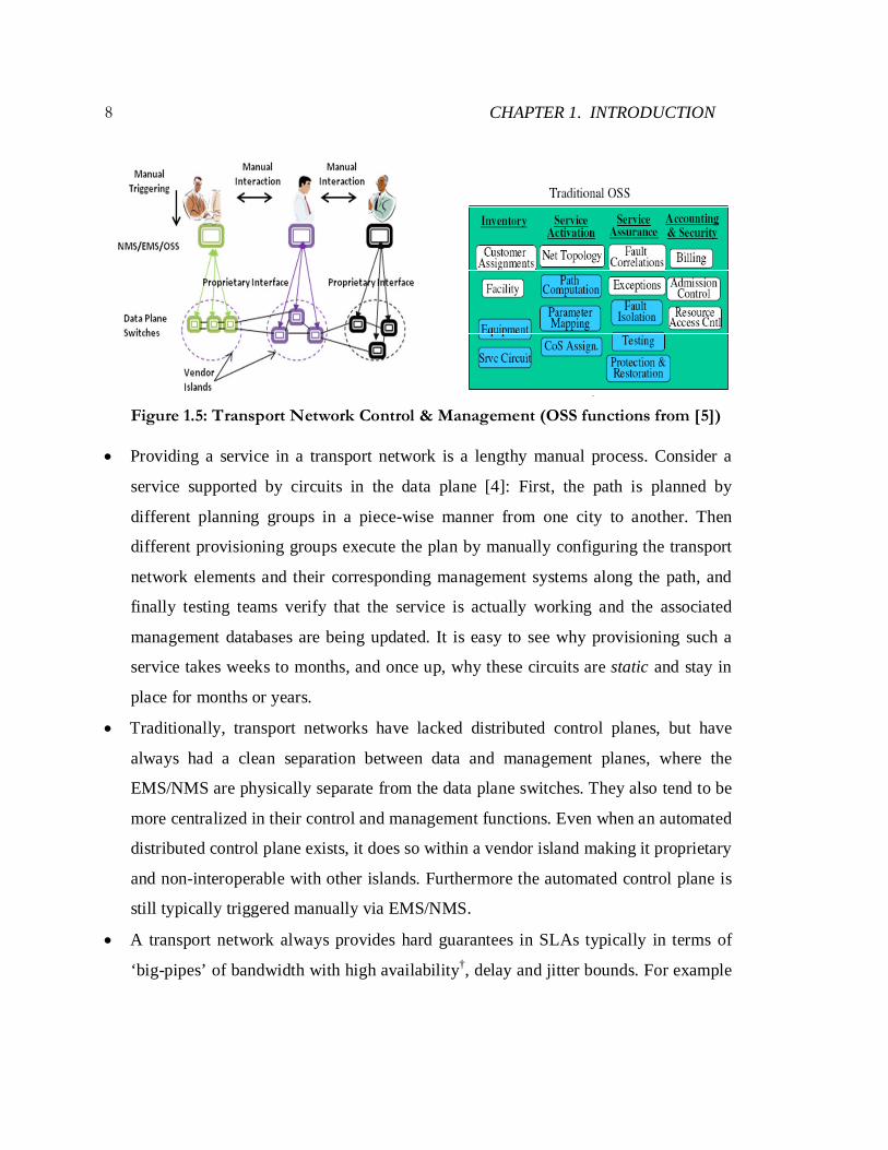
Figure 1.5: Transport Network Control & Management (OSS functions from [5])
• Providing a service in a transport network is a lengthy manual process. Consider a
service supported by circuits in the data plane [4]: First, the path is planned by
different planning groups in a piece-wise manner from one city to another. Then
different provisioning groups execute the plan by manually configuring the transport
network elements and their corresponding management systems along the path, and
finally testing teams verify that the service is actually working and the associated
management databases are being updated. It is easy to see why provisioning such a
service takes weeks to months, and once up, why these circuits are static and stay in
place for months or years.
• Traditionally, transport networks have lacked distributed control planes, but have
always had a clean separation between data and management planes, where the
EMS/NMS are physically separate from the data plane switches. They also tend to be
more centralized in their control and management functions. Even when an automated
distributed control plane exists, it does so within a vendor island making it proprietary
and non-interoperable with other islands. Furthermore the automated control plane is
still typically triggered manually via EMS/NMS.
• A transport network always provides hard guarantees in SLAs typically in terms of
‘big-pipes’ of bandwidth with high availability†, delay and jitter bounds. For example
9
- guaranteed 10Gbps from point A to point B with 99.999% availability – the latter is
known as five 9s availability which corresponds to about 5mins of downtime in a
year. The ‘big-pipe’ granularity comes from the fact that in most cases, traffic has
been aggregated the point where they require big pipes for transport. But it also stems
from the fact that because it takes so long for a customer to ‘get’ such a service, the
customer often prefers to get more at one time and keep it for a long time (static)
without having to ask for more (and be subject to the long provisioning times).
1.2 Problem Statement
Service providers such as AT&T and Verizon today separately own and operate two
distinct wide-area networks: packet-switched IP/MPLS networks and circuit-switched
TDM/WDM transport networks. In fact, the biggest transport service providers
(carriers/telcos) in the world are also the biggest Internet Service Providers (ISPs). For
example, traditional carriers like AT&T, Verizon, British Telecom, Deutsche Telekom,
NTT, Level 3/Global Crossing, Tata and others are also Tier 1 and Tier 2 ISPs [6].
These two networks are typically planned, designed and managed by separate
divisions even within the same organization. Clearly owning and operating two separate
networks is inefficient. At the very least, it leads to substantial management overhead
from two teams of operators trained on different modes of operation and different
management tools. But more importantly, it has a profound effect in terms of the Total
Cost of Ownership (TCO).
Capex: To cope with Internet traffic growth (40-50% per year [7]), carriers would
like to see lower Capex per Gbps† when upgrading their infrastructure. However, this has
not been true in practice*. Operating two networks separately typically involves
functionality and resource duplication across layers. Fault tolerance is a prime example:
The underlying transport network often operates with 1:1 protection, while the IP
† For example, a 2X increase in cost for a 4X increase in capacity * Upgrading from 10G to 40G links required more than 4X increase in equipment cost [9]
10
CHAPTER 1. INTRODUCTION
network running on top operates at less than 30% link utilization in preparation for
unexpected traffic surges and link failures.
Opex: Operational expenditures can account for nearly 60-80% of the Total Cost of
Ownership (TCO) of the network^. Such cost involve labor costs; costs for network
Operations, Administration, Maintenance and Provisioning (OAM&P); equipment rack
and PoP/CO† building rentals; and power consumption for operation and cooling.
Separate operation of the two networks also involves time and labor-intensive manual
coordination between the teams for service provisioning and maintenance tasks.
Service-Differentiation/Innovation: Service providers find it hard to
differentiate their service-offerings from other carriers. Networks today are built using
closed-systems (routers and switches) from the same set of vendors with the same set of
features. The features are private “secret sauce” created inside each vendor's product. As
a result, features are frozen inside each box, making innovation slow. The vendors have
little incentive to innovate and create a barrier to entry for others, in both IP and transport
networks.
Thus it is clear that from a service provider perspective, two separate networks that
operate differently are inefficient. In networking, two is simply not better than one. In
this thesis, we ask the question – is there a way to run one network instead of two? The
problems outlined above led us to define three main goals underlying our work:
• To simplify and unify the control and management of IP and transport networks, so
that the network can be jointly optimized to provide the best service for customers.
Today, these planes are so different, and so complicated, that this is not feasible.
• Allow network operators to create and add new features to their packet and optical
networks to provide revenue generating services that differentiate them from other
carriers, thereby enabling a path of continuous innovation in the infrastructure.
• To allow network operators to use lower cost, lower power and more scalable optical
Layer 1 transport switches in places they would use large, complex IP routers today.
† PoP – Point-of-Presence; CO- Central Office ^ From private communications with several large carriers.
11
1.3 State of the Art
In this section, we discuss two topics that are state-of-the-art for IP and transport
networks. The first involves a viewpoint popularly held by router-vendors. The second
discusses the only previous attempt at unifying the control of the two networks.
1.3.1 IP over WDM
In this viewpoint, running one network instead of two can simply be achieved by
eliminating circuit switching between the routers.
Recall that in Section 1.1.2, we stated that the transport network currently supports
multiple client networks (Fig. 1.4). In recent years, there has been a trend to migrate the
other client networks to the Internet. For example, traditional voice services are moving
to IP, both at the end-user and in the service provider’s core.Meanwhile 4G cellular
networks are also transitioning to all-IP networks for both data and voice. Previously (in
2G/3G) they used the IP network for data but circuit-switched networks for voice.
Finally, point-to-point private-lines and enterprise private-network customers are
increasingly moving to packet-network based solutions (eg. VPNs).
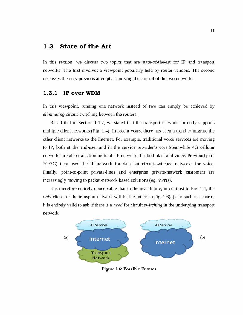
It is therefore entirely conceivable that in the near future, in contrast to Fig. 1.4, the
only client for the transport network will be the Internet (Fig. 1.6(a)). In such a scenario,
it is entirely valid to ask if there is a need for circuit switching in the underlying transport
network.
Figure 1.6: Possible Futures
(a) (b)

12
CHAPTER 1. INTRODUCTION
For example, IP routers could be directly connected by point-to-point optical WDM
links, in which case the WDM line systems are subsumed by the IP network (Fig. 1.6(b))
and transport switching is entirely eliminated – IP over WDM (no circuit switches).
We don’t believe circuit switching will (or should) be eliminated. On the contrary, we
believe that circuit switching is here to stay in the core, as it can make the Internet more
efficient, with the caveat that for this to happen, the two networks must work together
dynamically.
Fundamentally, packet switching is always going to be more expensive than circuit
switching, simply because it performs a lot more functions, and does so at a much smaller
granularity at much faster time-scales. In Appendix A, we show that our expectations are
matched by numbers we obtain from real-world packet and circuit switches in the
industry. Circuit switches are much more scalable; a circuit switch can switch much
higher data rates, and consume much less power than an electronic packet switch. A
useful rule of thumb is that an optical circuit switch consumes about 1/10th of the volume,
1/10th of the power and costs about 1/10th the price as an electronic packet switch with the
same capacity (Appendix A). As a consequence, they are simpler, lower cost and more
space efficient than an electronic packet switch.
This is not an attempt to say that packet and circuit switches are equivalent, because
clearly they are not – while they both provide connectivity, they do so very differently.
However, there are some functions that circuits can perform exceedingly well in the core
– functions like recovery, bandwidth-on-demand, and providing guarantees (which we
discuss in Chapter 3) – such that if circuits are eliminated, and those functions are then
provided by packets, it comes at the cost of price (Capex), power consumption and size
(Opex). In Chapter 4, we show the Capex and Opex inefficiencies of designing an IP-
over-WDM network (without circuit switching), when compared to a packet network that
interacts with a dynamic-circuit-switched network under common control.
On the other hand, a circuit switch doesn’t have the statistical multiplexing benefits of
a packet switch. This matters little at the core of the network where flows destined to the

13
same next hop are naturally bundled, and their aggregate is relatively smooth [9]. Closer
to the edge of the network, however, packet switching offers big benefits due to statistical
multiplexing and more fine-grain control.
Thus we believe that packet switching is here to stay at the edge and dynamic-circuits
offer significant advantages in the core. Indeed others have shown similar benefits [10,
79, 82-84].We do not know where the boundary between the edge and core lies, but
preferably it is a flexible one. Diversity in the data plane is beneficial as both packets and
circuits offer unique capabilities and cost vs. performance benefits in the data plane. But
there is no real need for diversity in the control plane! And so the only way to run one
network instead of two is to have a single converged control plane for packet and circuit
switched networks. This thesis proposes a means for achieving such convergence.
1.3.2 MPLS/GMPLS
We are not the first to suggest a unified way to control packet and circuit switches. Most
notably GMPLS offered an alternative approach [19], which has undergone
standardization within the IETF (since 2000 [20]), and variations of the protocol suite
have also gone through standardization at the ITU [21] and the OIF [22].
Generalized Multi-Protocol Label Switching (GMPLS) was designed as a superset of
MPLS, and intended to offer an intelligent and automated unified control plane (UCP) for
a variety of networking technologies – both packet and circuit. Its origin could be traced
to the fact that MPLS already enforced a flow abstraction in core IP networks. Since
circuits could readily be thought of as flows, a common-flow abstraction seemed natural.
The logical next step involved developing a unified control framework on top of this
common flow abstraction. And since MPLS already had a well developed control plane
(derived from a well-developed IP control plane), GMPLS simply extended the same
distributed routing and signaling protocols (OSPF-TE, RSVP-TE) to control circuit
switches [5, 23-25].

14
CHAPTER 1. INTRODUCTION
However, despite a decade of standardization, implementation by transport equipment
vendors and several interoperability demonstrations, GMPLS has yet to see even one
significant commercial deployment as a unified control plane across packets and circuits.
In fact, it isn’t even used as a control plane just for transport networks [26, 27].
We do believe that the initial choice to use the concept of a flow in the data plane as
the common abstraction was the right one. However, the subsequent choices either made
or overlooked have contributed significantly to its failure. In the rest of this thesis, we
will offer our perspective on where GMPLS went wrong, by highlighting these choices
and comparing and contrasting our solution to them [29].
One fundamental observation we make here is that MPLS/GMPLS networks lack the
common-map abstraction, and in principle all other deficiencies can be traced back to this
observation. For example, without the common-map abstraction you lose the ability to
implement control-functions in a centralized way. As a result features have to be
implemented in a distributed way and be dependent in subtle ways on distributed
protocols, increasing complexity and reducing extensibility (which we show in Chapter
3). Additionally using distributed protocols has its own issues with stability and being
able to provide a gradual adoption path (Chapter 3). And without the common map you
lose visibility across packets and circuits, which in turn makes services dependant on an
interface such as the UNI [22], where the possible service requirements have been pre-
supposed (pre-defined) and baked into the protocols, thereby hurting programmability
and extensibility (also discussed in Chapter 3). Ultimately we argue that only control
architectural changes will enable true converged operation.
1.4 Proposed Solution: Unified Control Architecture
Accomplishing the goal of a unified control plane for packet and circuit networks is not
trivial. From our discussion in Sec. 1.1, it is easy to see that the control and management
architectures of the two networks are vastly different (upper half of Fig. 1.7).

15
Furthermore the data plane units of packets and circuits (wavelengths, time-slots etc.) are
also quite different from a control perspective.
Figure 1.7: Path to Convergence
Thus in order to create commonly-operated converged packet and circuit networks,
we ask ourselves the following questions (lower half of Fig. 1.7):
1. Can we find a common data-plane construct that would apply to both packets and
circuits? Essentially a common data-plane abstraction that would provide a common
paradigm for simple multi-layer control; one that allows flexible and vendor agnostic
interfaces that can eliminate vendor islands and proprietary interfaces in running
multi-vendor networks?
2. Can we develop a separate, common control construct that represents the networks in
a common way? One that eases the development and fast deployment of automated

16
CHAPTER 1. INTRODUCTION
network-functions and services across packets and circuits, while giving the network
operator the choice of selecting the best mix of technologies for their service needs?
We believe that such constructs are indeed possible, but require changes in control
architecture. And so we propose a unified control architecture which has its
underpinnings in two abstractions – the common flow abstraction and the common-map
abstraction [11, 13]. Our work is heavily influenced by an emerging new direction in
packet networks called “Software Defined Networking (SDN)” [16, 17]. SDN origins lie
in fostering innovation in campus networks, by enabling researchers and network
operators to experiment with new ideas ‘in’ the networks they use every day [12]. It was
born out of related work that looked at security management issues in enterprise networks
(ETHANE project [18]). We have applied SDN ideas to circuit-switching and carrier
networks to propose a solution to converged operation of IP and transport networks.
1.4.1 Common Flow Abstraction
In a traditional IP backbone network, routers use a ‘datagram’ model, where they deal
with each packet in isolation, rather than viewing the packets as part of some end-to-end
communication. In other words, treatment given to a packet is independent of what
packets came before or what packets might come afterwards.
But data-packets are naturally part of flows – i.e. they are naturally part of some
communication (not necessarily end-to-end). Packets that are part of the same
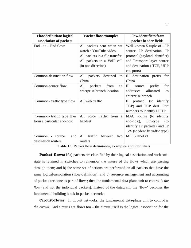
communication have the same logical association. Consider Table 1.1: it shows multiple
different definitions of flows (i.e. different logical associations between packets); gives
examples of what these flows can represent, and in the last column presents ways to
identify these flows from fields in the packet-headers. The concept of flows is not a new
one. In core networks today, flows exist as FECs coupled with LSPs (we discuss this in
more detail in Chapter 5). To define the common-flow abstraction, we define flows in the
following way:
17
Flow definition: logical association of packets
Packet flow examples Flow-identifiers from packet header fields
End – to – End flows All packets sent when we watch a YouTube video All packets in a file transfer All packets in a VoIP call (in one direction)
Well known 5-tuple of - IP source, IP destination, IP protocol (payload identifier) and Transport layer source and destination ( TCP, UDP etc. ports)
Common-destination flow All packets destined to China
IP destination prefix for China
Common-source flow All packets from an enterprise branch location
IP source prefix for addresses allocated to enterprise branch
Common- traffic type flow All web traffic IP protocol (to identify TCP) and TCP dest. Port numbers to identify HTTP
Common- traffic type flow from a particular end-host
All voice traffic from a handset
MAC source (to identify end-host), Eth-type (to identify IP packets) and IP ToS (to identify traffic type)
Common - source and destination routers
All traffic between two routers
MPLS label id
Table 1.1: Packet flow definitions, examples and identifiers
Packet-flows: If a) packets are classified by their logical association and such soft-
state is retained in switches to remember the nature of the flows which are passing
through them; and b) the same set of actions are performed on all packets that have the
same logical-association (flow-definition); and c) resource management and accounting
of packets are done as part of flows; then the fundamental data-plane unit to control is the
flow (and not the individual packets). Instead of the datagram, the ‘flow’ becomes the
fundamental building block in packet networks.
Circuit-flows: In circuit networks, the fundamental data-plane unit to control is
the circuit. And circuits are flows too – the circuit itself is the logical association for the
18
CHAPTER 1. INTRODUCTION
data that is being carried in it between two end-points in a network. Only the flow
identifiers for circuit flows are different from packet-flows. For example a circuit-flow
could be:
• a time-slot on multiple links, making up a TDM signal-path, or
• a collection of time slots, on multiple different paths, bound together, or
• a single wavelength-path, or
• a wavelength path comprising different wavelengths along the path, or
• a set of timeslots on a particular wavelength, or
• a waveband – i.e. collection of wavelengths along a path.
Note the similarity of the above example for circuit-flows to the examples for packet
flows in the middle column of Table 1.1.
Common-Flow Abstraction: It is easy to see that in most cases, the
information identifying the logical association of packets in a packet-flow exists within
the header fields of all the packets in the flow. And while the identifiers of circuit flows
are different, both sets of identifiers can be placed in forwarding tables found in both
packet and circuit switches (Fig. 1.8).
For packet switches the forwarding tables take the form of lookup-tables which can
match incoming packet header-fields to ‘rules’ that define the flow. These rules are
combinations of flow-identifiers (right-most column in Table 1.1) that embody the logical
association between packets that are part of the same flow. Most packet-switches support
lookup tables that match on only one kind of identifier – eg. Ethernet switches match on
MAC addresses, IP routers match on IP addresses etc. But all packet-switches also
support other tables (eg. Ternary CAMs) which allow flexible rule definitions that
include combinations of identifiers as well as ‘don’t cares’. These tables support flexible
rules-definitions for packet flows, and perform the same actions on all packets that match
the rule. Thus with a packet-switch abstraction of <matching-rule, actions, statistics>, an
incoming <packet, port> can be translated to an outgoing <packet’, port’> [12].

19
Figure 1.8: Packet Switch and Circuit Switch Internals (Appendix A)
For circuit switches the forwarding tables are cross-connect tables that control the
scheduling of the circuit switch fabric to create a circuit within the switch. In circuit
switches the forwarding table is not in the datapath. Nevertheless, the table supports a
translation of an incoming wavelength, time-slot or fiber-port (λ, t, port) to an outgoing
(λ’, t’, port’). Thus a circuit switch can also be abstracted as a table that supports
<cross-connect rules, actions, statistics> [13].
The common-flow abstraction (Fig. 1.9) is therefore a common-forwarding
abstraction (or a common-table abstraction), where we abstract away all kinds of packet
and circuit switch hardware, by presenting them as forwarding tables for direct
manipulation by a switch-API. In other words, switches are no longer viewed as Ethernet
switches, IP routers, L4 switches, MPLS LSRs, SONET switches, OTN switches,
ROADMS, or multi-layer switches – they are just tables; tables that support the flow
identifiers irrespective of which traditional layer of networking (L0-L4), or combination
of them, the flow may be defined with. In Appendix B we describe a switch-API for
manipulating our common-table abstraction.
20
CHAPTER 1. INTRODUCTION
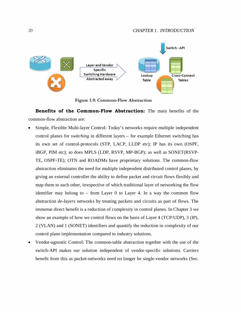
Figure 1.9: Common-Flow Abstraction
Benefits of the Common-Flow Abstraction: The main benefits of the
common-flow abstraction are:
• Simple, Flexible Multi-layer Control: Today’s networks require multiple independent
control planes for switching in different layers – for example Ethernet switching has
its own set of control-protocols (STP, LACP, LLDP etc); IP has its own (OSPF,
iBGP, PIM etc); so does MPLS (LDP, RSVP, MP-BGP); as well as SONET(RSVP-
TE, OSPF-TE); OTN and ROADMs have proprietary solutions. The common-flow
abstraction eliminates the need for multiple independent distributed control planes, by
giving an external controller the ability to define packet and circuit flows flexibly and
map them to each other, irrespective of which traditional layer of networking the flow
identifier may belong to – from Layer 0 to Layer 4. In a way the common flow
abstraction de-layers networks by treating packets and circuits as part of flows. The
immense direct benefit is a reduction of complexity in control planes. In Chapter 3 we
show an example of how we control flows on the basis of Layer 4 (TCP/UDP), 3 (IP),
2 (VLAN) and 1 (SONET) identifiers and quantify the reduction in complexity of our
control plane implementation compared to industry solutions.
• Vendor-agnostic Control: The common-table abstraction together with the use of the
switch-API makes our solution independent of vendor-specific solutions. Carriers
benefit from this as packet-networks need no longer be single-vendor networks (Sec.

21
1.1.1) while remaining fully automated and feature-rich. Similarly carriers can
eliminate multiple non-interoperable vendor-islands in transport networks (Sec.
1.1.2). The ability to run multi-vendor automated converged packet-circuit networks
fully interoperable in the control plane provides an economic benefit which we will
quantify in Chapter 4.
To summarize, the common-flow abstraction is a common-forwarding abstraction that
lets us think of packets and circuits commonly as flows, thereby providing a common
paradigm for flexible and vendor-agnostic control across multi-layer networks.
1.4.2 Common Map Abstraction
We find that in modern networks, there are several functions that we need from the
network itself– examples of these functions are routing, access-control, mobility, traffic-
engineering, guarantees, recovery, bandwidth-on-demand – the list goes on. Some of
these may apply to packets-networks, some to circuits-networks, and some to both.
Ultimately these functions are implemented as control programs. And these control
programs are easiest to write when they operate in a centralized way, with a global view
of the network – both packet and circuit. Thus the second abstraction is a common-map
abstraction across both packet and circuit switched networks. The global-map is an
annotated graph of the network topology which we describe next.
Common-Map: The global-map is a database of the network topology (Fig. 1.10).
It is a collection of network nodes - both packet and circuit switches. The node’s
switching capabilities are represented by their forwarding tables (the common-flow
abstraction) together with the features the tables support (match-fields, cross-connections,
forwarding actions, mapping actions etc.). The switch information also includes
collections of entities such as ports, queues, and outgoing link information. Example
attributes of each entity are listed in Fig. 1.8. This database is created, presented to
control applications and kept up-to-date by the map-abstraction.

22
CHAPTER 1. INTRODUCTION
Figure 1.10: Annotated Graph (Database) of Network Topology
Aside from the nodes and links another database for flow-state can be created if the
control applications need to retain such information. Fig. 1.11 shows the entities involved
in retaining packet and circuit flow-state and their attributes. While the flow (both packet
and circuit flows) databases can be a part of the common-map as they reflect network
state (Fig.1.9), the decision to retain such state is left up to the control application. This is
because flow-state is typically ephemeral, and knowledge of individual flow-state is
usually not necessary for making control decisions. What is necessary is the aggregate
effect the flows have on various parts of common-map. Such aggregates are reflected in
the statistics maintained in common-map entities (tables, ports, queues etc.).
23
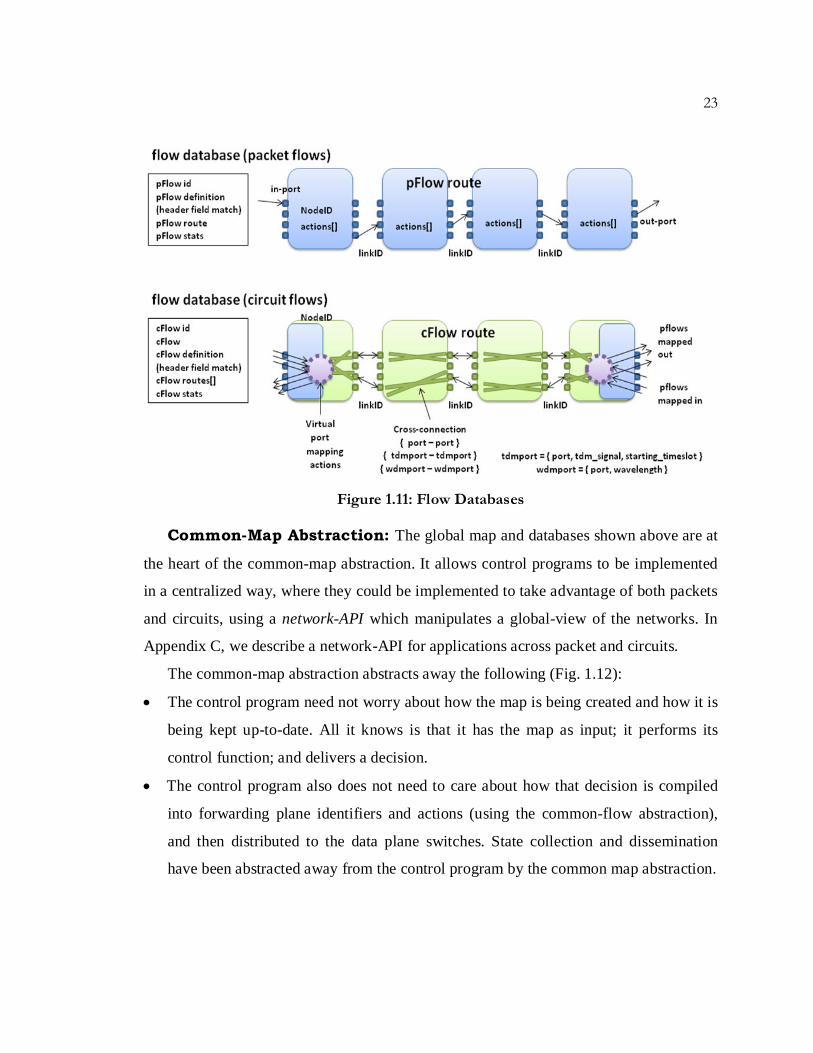
Figure 1.11: Flow Databases
Common-Map Abstraction: The global map and databases shown above are at
the heart of the common-map abstraction. It allows control programs to be implemented
in a centralized way, where they could be implemented to take advantage of both packets
and circuits, using a network-API which manipulates a global-view of the networks. In
Appendix C, we describe a network-API for applications across packet and circuits.
The common-map abstraction abstracts away the following (Fig. 1.12):
• The control program need not worry about how the map is being created and how it is
being kept up-to-date. All it knows is that it has the map as input; it performs its
control function; and delivers a decision.
• The control program also does not need to care about how that decision is compiled
into forwarding plane identifiers and actions (using the common-flow abstraction),
and then distributed to the data plane switches. State collection and dissemination
have been abstracted away from the control program by the common map abstraction.

24
CHAPTER 1. INTRODUCTION
• Finally, each individual control function does not have to worry about conflicts that
may arise between decisions it makes and decisions made by other control functions.
Thus application-isolation is part of the abstraction provided to control functions.
Figure 1.12: Common-Map Abstraction
Benefits of the Common-Map Abstraction: The main benefits of the
common-map abstraction are:
• Programmability: Instead of defining network behavior up-front and baking it into the
infrastructure, the common-map abstraction helps networks become programmable. It
eases the path to innovation by offering a network API to programs for controlling
network behavior. What does the network API include? Today, the three networking
tasks of: i) configuring switches; ii) controlling forwarding behavior; and iii)
monitoring network state; are performed separately. Configuration typically uses a
CLI or NMS/EMS, forwarding state is determined by distributed routing/signaling or
other special purpose protocols, and monitoring is done via SNMP, NMS/EMS,
Netflow, sFlow etc. The network API can present calls for all three tasks together to
network applications.
• Simplicity & Extensibility: The common-map abstraction breaks the chains that bind
together today’s distributed-implementation of network services to the state-

25
distribution mechanisms that support them. With the common-map abstraction the
distribution mechanisms are abstracted away, so the control function can be
implemented in a centralized way. Centralization makes implementing individual
control functions simpler; but just as importantly the abstraction makes inserting new
control functions into the network easy (extensible). This is because the state-
dissemination problem has been solved once and abstracted away, so new control-
programs do not have to worry about it by creating new distribution mechanisms or
changing existing ones. We will show examples of simplicity and extensibility in
writing control-programs in Chapter 3.
• Joint & Global Optimization: The common map-abstraction offers full visibility
across packets and circuits. In other words it offers applications the ability to perform
joint-optimization of network functions and services across both technologies;
leveraging off the different-benefits of both packet and circuit switching; and doing
so with a global view of the network.
• Choice: With the common-map abstraction and its global view, new features can be
supported that take advantage of both packets and circuits. Additionally it allows the
network programmer the choice of writing control programs in a variety of ways in
the context of packet and circuit networks. A particular control program could still
treat the packet and circuit flows as if they were in different layers, where they would
have separate topologies, but still be commonly controlled. A different control
program could treat them as part of the same layer with a single topology (and still
commonly controlled). Yet another control program could go further and treat them
as separate topologies while completely ignoring one of them. The common-map
abstraction does not preclude any of the cases, and we will give examples of all of
these cases in Chapters 3 and 5. In other words, with the common-map abstraction,
the control function programmer/network operator has maximum flexibility to choose
the correct mix of technologies for the services they provide.
26
CHAPTER 1. INTRODUCTION
1.4.3 Unified Control Architecture
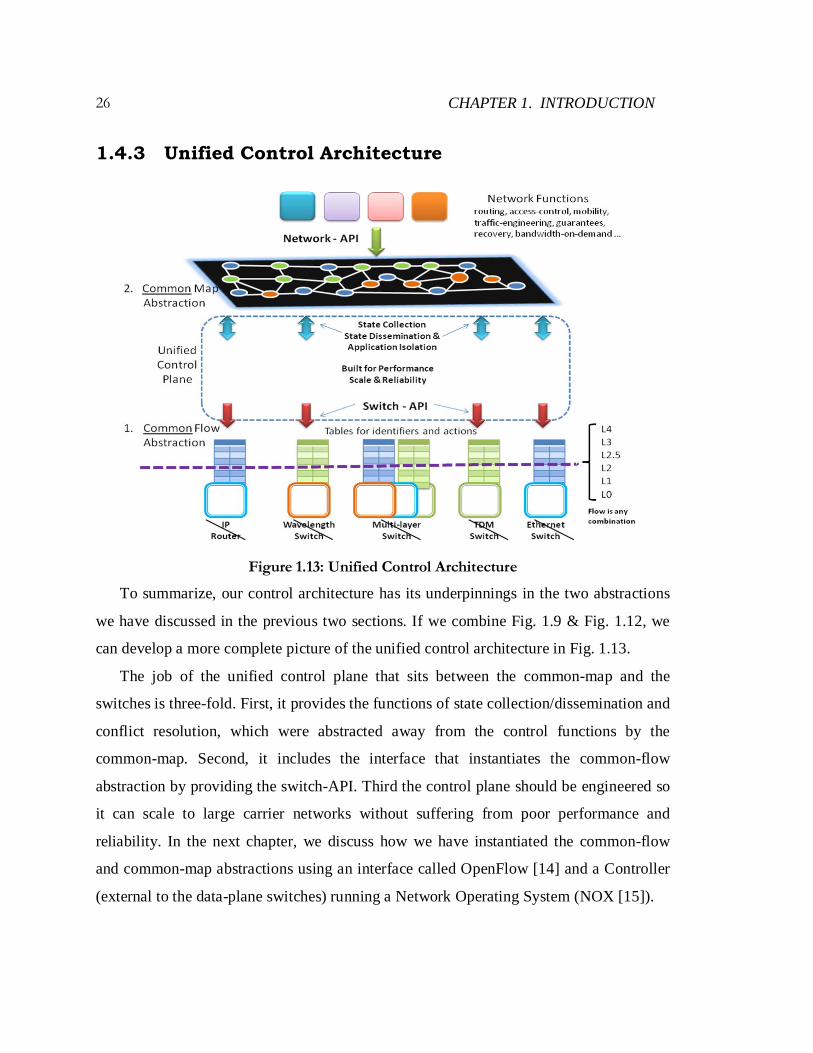
Figure 1.13: Unified Control Architecture
To summarize, our control architecture has its underpinnings in the two abstractions
we have discussed in the previous two sections. If we combine Fig. 1.9 & Fig. 1.12, we
can develop a more complete picture of the unified control architecture in Fig. 1.13.
The job of the unified control plane that sits between the common-map and the
switches is three-fold. First, it provides the functions of state collection/dissemination and
conflict resolution, which were abstracted away from the control functions by the
common-map. Second, it includes the interface that instantiates the common-flow
abstraction by providing the switch-API. Third the control plane should be engineered so
it can scale to large carrier networks without suffering from poor performance and
reliability. In the next chapter, we discuss how we have instantiated the common-flow
and common-map abstractions using an interface called OpenFlow [14] and a Controller
(external to the data-plane switches) running a Network Operating System (NOX [15]).

27
1.5 Contributions of Thesis
This thesis makes the following contributions:
Architecture: We have proposed and defined a unified control architecture for the
converged operation of packet and circuit switched networks. The architectural
underpinnings of our proposal include:
• A common-flow abstraction: that provides a common paradigm for flexible control
across packet and circuit switches. We instantiated the common-flow abstraction by
first creating a flow-table based abstraction for different kinds of circuit switches. We
took into account switching-fabric types and port/ bandwidth representations, as well
as various ways in which packet and circuit switches can be interconnected based on
interface-type, framing method and line-rates (Ch.2). We also developed a switch-
API for creating, modifying and deleting circuit flows; mapping packet-flows to
circuit-flows and back with suitable adaptations; neighbor discovery and recovery
messages; and finally error and statistics messages for circuit ports, links and flows
(Ch.2 and Appendix B). OpenFlow v1.0 [28] was extended to include this API.
• A common-map abstraction: that liberates network control functions from the task of
distributed state collection and dissemination. We extended an existing Controller
called NOX [15] to simultaneously control both packet and circuit switches, thereby
creating an instance of the common-map abstraction. We also developed link-
discovery methods that do not preclude a layering choice and created a network-API
for applications to manipulate the common-map (Ch.2 and Appendix C).
Validation of Architectural Benefits: We implemented our architectural
approach in several prototypes (named pac.c for packet and circuit .convergence) to
validate the simplicity and extensibility of our approach:
• We built three pac.c prototypes - the first two systems demonstrated common control
over packet switches and two different kinds of circuit switches – a TDM based one

28
CHAPTER 1. INTRODUCTION
and the other a WDM based one. The more complete pac.c prototype, was used to
emulate an inter-city wide-area network structure, with packet switches in 3 cities
interconnected by circuit switches in the backbone, all under unified operation.
• We validated the simplicity of our proposed solution by:
o Implementing and demonstrating a network-application across packets and
circuits on top of our prototype emulated WAN – the network-application’s goal
was to treat different kinds of network-traffic differently.
o Comparing our work to existing network control solutions - we found that
implementation of the defined control-function in our control architecture takes 2
orders of magnitude less lines-of-code compared to existing solutions.
• We validated the extensibility of network-control functions in our architecture by:
o Identifying and demonstrating multiple networking-applications across packets
and circuits on our pac.c prototype. Examples include: Variable Bandwidth
Packet Links; Dynamic Optical Bypass; Unified Routing & Recovery. The
applications suggested are by no means the only possible applications, as service
providers can define their own applications to meet their service needs.
o Comparing our work to existing network control solutions – we show how
existing rigid control interfaces cannot reproduce our network applications
exactly, nor can they easily add new services given the tight coupling between
applications and state distribution mechanisms.
Design & Analysis: We designed WAN infrastructures and performed Capex and
Opex analyses on them to validate cost-savings from operating a network with both
packet and circuit switching if done from a single control viewpoint -- i.e. using our
unified control architecture.
• We outlined a design procedure for IP over WDM networks (reference design) and
applied a cost-model to the components. Our Capex analysis for this reference design
is more detailed than previous attempts, as we include access routers and dimension

29
the IP network for recovery and traffic uncertainty. We accounted for static optical
bypass in our IP over WDM reference design and showed a 10-15% decrease in
Capex. We have also shown that this gain levels off as we add more bypass.
• Next, we outlined a design procedure that modeled a converged packet-circuit
network based on our unified control architecture. Overall Capex and Opex savings
of nearly 60% and 40% respectively are achieved in comparison to today’s IP-over-
WDM core networks. Furthermore such savings are found to be insensitive to varying
traffic-matrices; and scale better (at a rate of $11m/Tbps vs. $26m/Tbps) as the
overall traffic grows to five times the original aggregate.
Introduced Map-Abstraction into MPLS based Networks: We have
mentioned before that MPLS networks have the flow-abstraction but lack the map-
abstraction. We further validated our architectural approach, by introducing the map-
abstraction into MPLS networks, and replicating services offered by MPLS today.
• We identified how we can replace all MPLS control plane functionality like
signaling (RSVP) and routing (OSPF) within a controller’s domain by writing
network applications on top of OpenFlow/NOX. We have replicated discovery,
recovery, label distribution, bandwidth reservation, and admission control via
Constrained SPF calculations, while still using the standard MPLS data-plane.
• We built another prototype to demonstrate an MPLS - Traffic Engineering service
that traffic engineered LSPs based on bandwidth-reservation and admission control.
We have also shown how our TE-LSPs can have all the features they have today
such as auto-bandwidth, priority, and explicit routes. Our solution again involved 2
orders of magnitude lesser line-of-code compared to the existing MPLS control.
• Finally we have identified opportunities where our control architecture can
potentially solve problems that the existing MPLS control cannot.
30
CHAPTER 1. INTRODUCTION
1.6 Organization of Thesis
This chapter is essentially an extended summary of the thesis. We briefly described the
significant differences in IP and transport network architectures, how they are separately
designed and controlled today, and then defined the problem statement as one where we
need to find a way to run one network instead of two. We discussed an alternative
viewpoint in which the goal of running one network can be achieved by eliminating
circuit switching in transport networks; but showed why both packets and circuits belong
in future networks and a better idea would be to converge their operation.
We proposed our solution to convergence – unified control architecture – as a
combination of two control abstractions: a common-flow abstraction and a common-map
abstraction. We showed how the former fits well with both types of network and provides
a common paradigm for control, while the latter makes it easy to insert new functionality
into the network. We briefly discussed a previous attempt at unified control (GMPLS)
and identified reasons for its failure, the fundamental one being the lack of a map
abstraction. And finally we summarized our contributions in the previous section. The
rest of this thesis is organized as follows.
In Chapter 2, we describe the common-flow and common-map abstractions in more
detail. We describe how packets and circuits can be abstracted as flows; and then delve
into abstractions for different kinds of circuit switches and requirements for a common-
switch API. Next we detail the representation, construction and maintenance of a
common-map as well as the requirements of a common-network-API. We present three
prototypes (named pac.c) we built to validate our architectural and control plane
constructs. We explore the extensions we have made to the OpenFlow interface to create
a common API for both kinds of switches, and the changes we made to a network-
operating-system (NOX) to have it present a common-map and network-API to network-
control-functions.

31
In Chapter 3, we demonstrate the simplicity and extensibility of our proposed unified
control architecture. First we demonstrate an implementation of a control function across
packets-and-circuits using our full pac.c prototype in an emulated-WAN structure. Then
we compare our implementation to one which would use existing control-solutions in the
industry today. Then we give examples of more new control applications across packet
and circuits, and show how our work is far more extensible than existing control-solution
in the industry. Finally we discuss solutions to three deployment challenges faced by any
unified control solution for packet and circuit networks.
In Chapter 4, we give a detailed example of today’s IP over WDM design
methodology, which we model as a reference design. We then propose a core network
that benefits from both packet-switching and dynamic circuit switching under an SDN
based unified control architecture. We perform a comprehensive Total Cost of Ownership
(TCO) analysis to judge the economic impact of our proposed changes. More
importantly, we provide technical solutions to practical issues that have hampered the
adoption of some of these ideas in the recent past.
In Chapter 5, we show how existing MPLS applications and services can be offered
by an IP/MPLS network based on our control architecture. We show that by introducing
the map-abstraction and retaining the MPLS data plane (flow abstraction) we can replace
all MPLS control-plane functionality. We present implementation details of our prototype
system where we have shown applications like MPLS Traffic Engineering on top of the
map abstraction. Finally, we discuss how introducing the map-abstraction in MPLS
networks fits well with our unified-control architecture for packet and circuit networks- a
fact that makes our control architecture ideal for multi-layer networks
We conclude in Chapter 6, and present related work and future research directions in
this area.