central processing unit (cpu)
TRANSCRIPT

1
CENTRAL PROCESSING UNIT (CPU)
n The solution algorithm consists of series of steps
n These steps are broken into smaller steps
n 1 steps = 1 machine instruction
n Each instruction is executed by carrying out a sequence of rudimentary/basic operations These operations anda how they are generated is one of the main topic of this course
Generated by Foxit PDF Creator © Foxit Softwarehttp://www.foxitsoftware.com For evaluation only.

2
FUNDAMENTAL CONCEPT
n The instructions are loaded in the sequential locations in main memory
n Instructions are fetch from successive memory locations
n PC (program counter) keeps track address of the next memory location containing next instruction (PC= PC +1)
Generated by Foxit PDF Creator © Foxit Softwarehttp://www.foxitsoftware.com For evaluation only.
3
THREE STEPS OF EXECUTION 1 INSTRUCTION
n 1. Fetch the contents of memory location pointed by PC, then loaded into IR (instruction register) IR ß[[ PC ]]
n 2 . Increment PC : PC ß PC +1
n 3 . Carry out the action by the instruction in the IR
n If the instruction more the 1 word, step 1 and 2 must be repeated as necessary
Generated by Foxit PDF Creator © Foxit Softwarehttp://www.foxitsoftware.com For evaluation only.

4
SINGLE BUS ORGANIZATION
Generated by Foxit PDF Creator © Foxit Softwarehttp://www.foxitsoftware.com For evaluation only.

5
OPERATION FUNCTIONS
n Fetch content of memory location and load into a CPU register (M àR)
n Store data from CPU register into memory location (R àM)
n Transfer from 1 register to another register (R ßà R)
n Perform arithmetic & logic operation and store the result in CPU register
n How each function is implemented in detail ?
Generated by Foxit PDF Creator © Foxit Softwarehttp://www.foxitsoftware.com For evaluation only.
6
Fetching a word from Memory
n Specify the address of memory location containing the instruction or operand, sent from CPU àMAR àmemory
n CPU send Read control signal
n After completing the operation, memory send the WMFC (wait for Memory Function Completed) signal to CPU, it means instruction/operand (requested) is available in the MDR
Generated by Foxit PDF Creator © Foxit Softwarehttp://www.foxitsoftware.com For evaluation only.
7
Sequence of Read operation
n Assumed memory address is in R1 and data from memory to be loaded into R2
n 1. MAR ß [R1]
n 2. Read
n 3. Wait for MFC signal
n 4. R2 ß [MDR]
n This type of data transfer is asynchronous transfer (combination of read request and MFC signal)
Generated by Foxit PDF Creator © Foxit Softwarehttp://www.foxitsoftware.com For evaluation only.
8
Storing a Word in Memory
n Address is loaded into MAR
n Data (to be written) is loaded into MDR
n Write signal is issued
n After completion of the operation, the memory will send the MFC signal
Generated by Foxit PDF Creator © Foxit Softwarehttp://www.foxitsoftware.com For evaluation only.
9
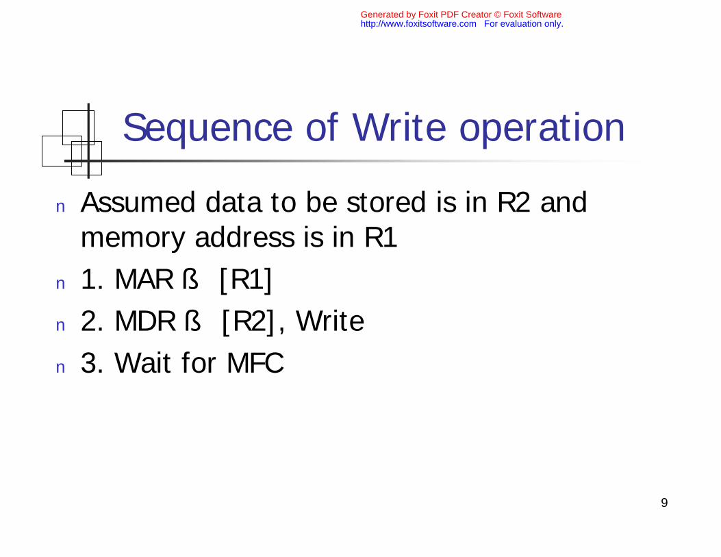
Sequence of Write operation
n Assumed data to be stored is in R2 and memory address is in R1
n 1. MAR ß [R1]
n 2. MDR ß [R2], Write
n 3. Wait for MFC
Generated by Foxit PDF Creator © Foxit Softwarehttp://www.foxitsoftware.com For evaluation only.

10
Register Transfer
n To control the gate for input the data into Riis used control signal Ri in
n To control the gate for output the data to the bus is used control signal Ri out
n To transfer contents of R1 to R4 :
n R1 out is set to 1 à output to the bus
n R4 in is set to 1 à load from the bus into R4
Generated by Foxit PDF Creator © Foxit Softwarehttp://www.foxitsoftware.com For evaluation only.

11
Arithmetic & Logic operation
n To add two numbers :
n First operand is hold on register Y
n Second operand is gated into the bus
n The result is store temporarily in reg Z
n Example : Add the contents of R1 to R2 and store the result in R3
Generated by Foxit PDF Creator © Foxit Softwarehttp://www.foxitsoftware.com For evaluation only.
12
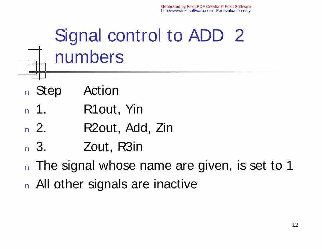
Signal control to ADD 2 numbers
n Step Action
n 1. R1out, Yin
n 2. R2out, Add, Zin
n 3. Zout, R3in
n The signal whose name are given, is set to 1
n All other signals are inactive
Generated by Foxit PDF Creator © Foxit Softwarehttp://www.foxitsoftware.com For evaluation only.
13
Execution a Complete Instruction
n The actions :
n 1. Fetch the instruction
n 2. Executions :
n Fetch operand(s)
n Perform the operations (Move, Add, etc.)
n Store the result to register or memory
Generated by Foxit PDF Creator © Foxit Softwarehttp://www.foxitsoftware.com For evaluation only.

14
Sequence control for instruction ADD LOC, R1
1. Pcout, MARin, Read, Clear Y, Set_carry_in_toALU, Add, Zin
2. Zout, PCin, Wait_for_MFC
3. MDRout, IRin
4. Address_field_of_IRout, MARin, Read
5. R1out, Yin, Wait_for_MFC
6. MDRout, Add, Zin
7. Zout, R1in, End.
Generated by Foxit PDF Creator © Foxit Softwarehttp://www.foxitsoftware.com For evaluation only.
15
DOUBLE BUS ORGANIZATION (1)
Generated by Foxit PDF Creator © Foxit Softwarehttp://www.foxitsoftware.com For evaluation only.
16
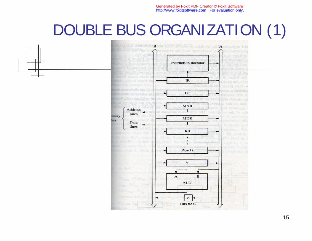
DOUBLE BUS ORGANIZATION (2)
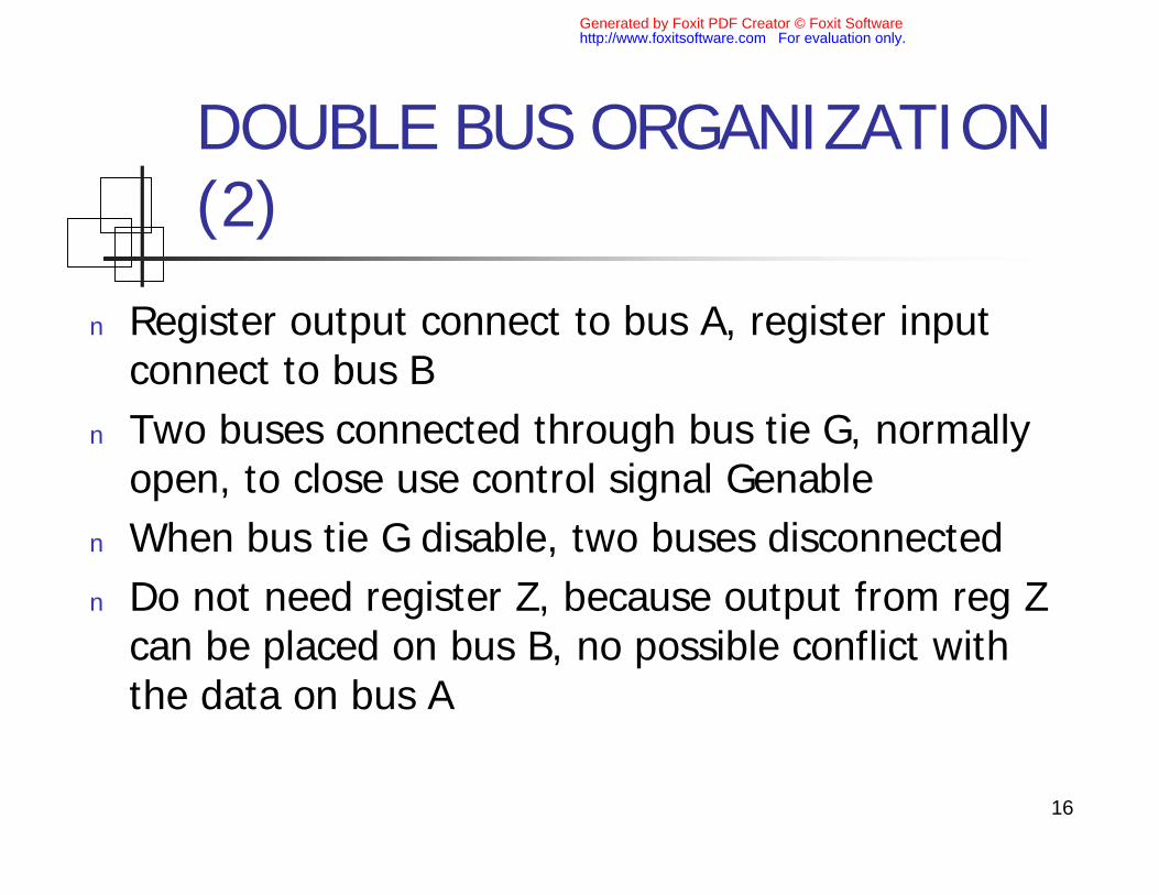
n Register output connect to bus A, register input connect to bus B
n Two buses connected through bus tie G, normally open, to close use control signal Genable
n When bus tie G disable, two buses disconnected
n Do not need register Z, because output from reg Z can be placed on bus B, no possible conflict with the data on bus A
Generated by Foxit PDF Creator © Foxit Softwarehttp://www.foxitsoftware.com For evaluation only.
17
DOUBLE BUS ORGANIZATION (3)
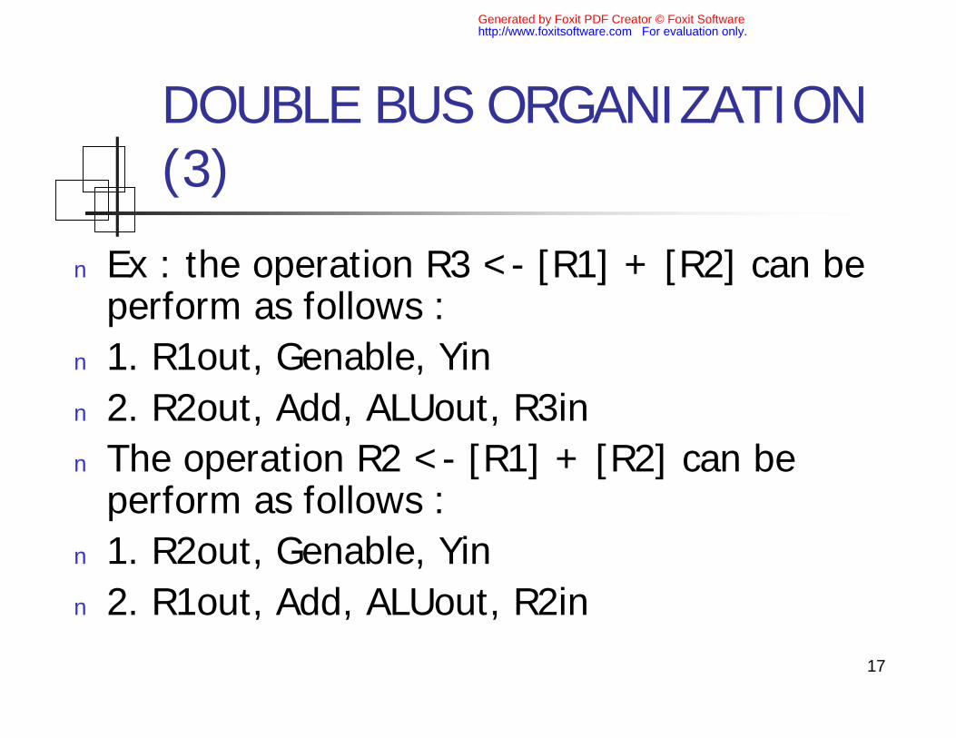
n Ex : the operation R3 <- [R1] + [R2] can be perform as follows :
n 1. R1out, Genable, Yin
n 2. R2out, Add, ALUout, R3in
n The operation R2 <- [R1] + [R2] can be perform as follows :
n 1. R2out, Genable, Yin
n 2. R1out, Add, ALUout, R2in
Generated by Foxit PDF Creator © Foxit Softwarehttp://www.foxitsoftware.com For evaluation only.
18
Branching
n Branching : replacing contents of PC by branch address
n Branch address = update PC + offset X
n Offset X is given in the address field of the branch instruction
n 2 type of branching :n Unconditional
n Conditional
Generated by Foxit PDF Creator © Foxit Softwarehttp://www.foxitsoftware.com For evaluation only.

19
Sequence control : Branch Unconditional
1. Pcout, MARin, Read, Clear Y, Set carry-in to ALU, Add, Zin
2. Zout, PCin, Wait_for_MFC
3. MDRout, IRin
4. PCout, Yin
5. Address_field_of_IRout, ADD, Zin
6. Zout, PCin, End.
Generated by Foxit PDF Creator © Foxit Softwarehttp://www.foxitsoftware.com For evaluation only.

20
CONDITION CODE
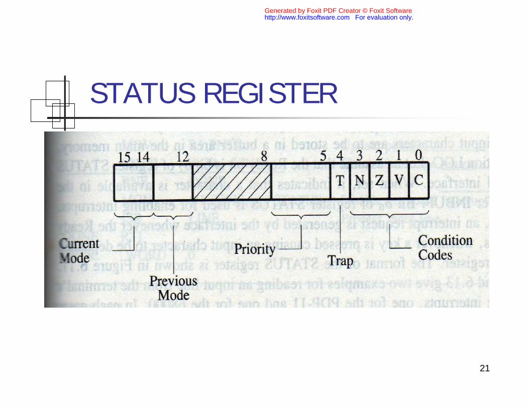
n Condition code flag is represent by a bit in the status register of the processor, to know the result of the last computing operation , there are :
n N (negative) : set to 1 if the result is negative, otherwise is 0
n Z (zero) : set to 1 if the result is 0, otherwise is 0
n V (overflow) : set to 1 of overflow occurs
n C (carry) : set to 1 if there are carry out result
Generated by Foxit PDF Creator © Foxit Softwarehttp://www.foxitsoftware.com For evaluation only.
21
STATUS REGISTER
Generated by Foxit PDF Creator © Foxit Softwarehttp://www.foxitsoftware.com For evaluation only.

22
Conditional Brach : Branch on Negative
1. Pcout, MARin, Read, Clear Y, Set carry-in to ALU, Add, Zin
2. Zout, PCin, Wait_for_MFC
3. MDRout, IRin
4. PCout, Yin, If N then End.
5. Address_field_of_IRout, ADD, Zin
6. Zout, PCin, End.
Step 4 : N is cheked, if N= 0 then End, if N=1, do step 5 and 6
Generated by Foxit PDF Creator © Foxit Softwarehttp://www.foxitsoftware.com For evaluation only.

23
Generating control signal to execute instructions
n 2 categories :
n A) Hardwired
n B) Microprogrammed Control
Generated by Foxit PDF Creator © Foxit Softwarehttp://www.foxitsoftware.com For evaluation only.
24
Hardwired Control
n The main part are decoder/encoder, simpya combinational circuit to generate signal control, depending on the state of all its input :
n Contents of control counter
n contents of instruction register
n Contents of condition code and other status flags
Generated by Foxit PDF Creator © Foxit Softwarehttp://www.foxitsoftware.com For evaluation only.
25
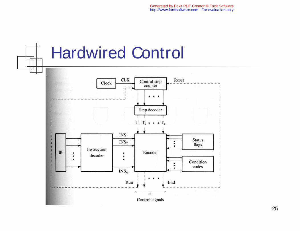
Hardwired Control
Generated by Foxit PDF Creator © Foxit Softwarehttp://www.foxitsoftware.com For evaluation only.
26
Hardwired (cont.)
n For any instruction loaded into IR, one of the output lines INS1 to INSm is set to 1
n All input signal to encoder block will be combined to generate individual control signal as Yin, PCout etc.
Generated by Foxit PDF Creator © Foxit Softwarehttp://www.foxitsoftware.com For evaluation only.
27
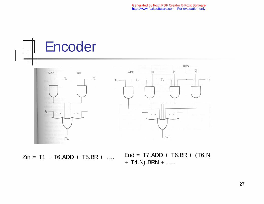
Encoder
Zin = T1 + T6.ADD + T5.BR + ….. End = T7.ADD + T6.BR + (T6.N + T4.N).BRN + …..
Generated by Foxit PDF Creator © Foxit Softwarehttp://www.foxitsoftware.com For evaluation only.
28
Microprogrammed Control
n Control signal are generated by a program similar to machine language program
n Each control signal is represent by individual bit stored in μprogrammed memory/control store
n Control unit generate control signal by reading sequentially control word from control store using μPC
Generated by Foxit PDF Creator © Foxit Softwarehttp://www.foxitsoftware.com For evaluation only.

29
Basic Organization of Microprogrammed Control Unit
Generated by Foxit PDF Creator © Foxit Softwarehttp://www.foxitsoftware.com For evaluation only.

30
Example of Microinstruction in µprogrammed memory
Generated by Foxit PDF Creator © Foxit Softwarehttp://www.foxitsoftware.com For evaluation only.