catalogue heating, air-conditioning, cooling circulating pumps · pump selection: general notes...
TRANSCRIPT
Glandless Pumpsand Accessories,Package Heat Exchanger Assembly
Catalogue Heating, Air-conditioning, Cooling
Circulating Pumps
Catalogue A1 - 50 Hz - 2008 A1

7
1
2
3
5
4
6
8
9
10
13
12
11
Wilo-Jet WJ
B1
1
Wilo-SubTW5-SE PnP
B1
2
Wilo-SilentMaster
B1
3
Wilo-Sub TWU 3
B1
4
Wilo-RainSystemAF Comfort
B1
5
Wilo-Comfort-Vario COR
B4
6
Wilo-Comfort-Vario CO 1/MVIE
B4
6
Wilo-StratosECO
A1
7
Wilo-Safe
A1
8
Wilo-Star-Z 15 TT
A1
9
Wilo-DrainLift Con
C3
10
Wilo-Stratos
A1
11
Wilo-Drain TM/TMW 32 Twister
C1
12
Wilo-DrainLift S
C3
13
Series Catalogue
Wilo-EMU KS
C1
1
Wilo-RainSystemAF 150
B1
2
Wilo-Comfort-VarioCOR 4
B4
3
Wilo-Stratos-D
A1
4
Wilo-CronoLine-IL-E
A2
5
Wilo-TOP-Z
A1
6
Wilo-Stratos
A1
7
Wilo-CronoBloc-BL
A3
8
Wilo-CronoBloc-BL
A3
8
Wilo-DrainLift M
C3
9
Wilo-DrainLift WS
C3
10
7
1
2
3
6
5
8
9
10
4
Series Catalogue
2 Subject to change without prior notice 09/2007 WILO AG
Program Overview and Fields of Application
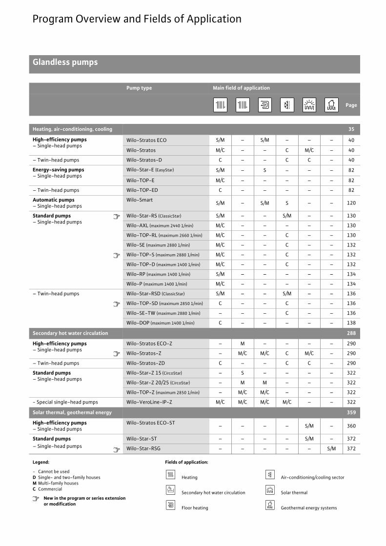
Glandless pumps
Pump type Main field of application
Page
Heating, air-conditioning, cooling 35
High-efficiency pumps– Single-head pumps
Wilo-Stratos ECO S/M – S/M – – – 40
Wilo-Stratos M/C – – C M/C – 40
– Twin-head pumps Wilo-Stratos-D C – – C C – 40
Energy-saving pumps– Single-head pumps
Wilo-Star-E (EasyStar) S/M – S – – – 82
Wilo-TOP-E M/C – – – – – 82
– Twin-head pumps Wilo-TOP-ED C – – – – – 82
Automatic pumps– Single-head pumps
Wilo-Smart S/M – S/M S – – 120
Standard pumps– Single-head pumps
Wilo-Star-RS (ClassicStar) S/M – – S/M – – 130
Wilo-AXL (maximum 2440 1/min) M/C – – – – – 130
Wilo-TOP-RL (maximum 2660 1/min) M/C – – C – – 130
Wilo-SE (maximum 2880 1/min) M/C – – C – – 132
Wilo-TOP-S (maximum 2880 1/min) M/C – – C – – 132
Wilo-TOP-D (maximum 1400 1/min) M/C – – C – – 132
Wilo-RP (maximum 1400 1/min) S/M – – – – – 134
Wilo-P (maximum 1400 1/min) M/C – – – – – 134
– Twin-head pumps Wilo-Star-RSD (ClassicStar) S/M – – S/M – – 136
Wilo-TOP-SD (maximum 2850 1/min) C – – C – – 136
Wilo-SE-TW (maximum 2880 1/min) – – – C – – 136
Wilo-DOP (maximum 1400 1/min) C – – – – – 138
Secondary hot water circulation 288
High-efficiency pumps– Single-head pumps
Wilo-Stratos ECO-Z – M – – – – 290
Wilo-Stratos-Z – M/C M/C C M/C – 290
– Twin-head pumps Wilo-Stratos-ZD C – – C C – 290
Standard pumps – Single-head pumps
Wilo-Star-Z 15 (CircoStar) – S – – – – 322
Wilo-Star-Z 20/25 (CircoStar) – M M – – – 322
Wilo-TOP-Z (maximum 2850 1/min) – M/C M/C – – – 322
- Special single-head pumps Wilo-VeroLine-IP-Z M/C M/C M/C M/C – – 322
Solar thermal, geothermal energy 359
High-efficiency pumps– Single-head pumps
Wilo-Stratos ECO-ST – – – – S/M – 360
Standard pumps– Single-head pumps
Wilo-Star-ST – – – – S/M – 372
Wilo-Star-RSG – – – – – S/M 372
Legend: Fields of application:
- Cannot be usedD Single- and two-family housesM Multi-family housesC Commercial
New in the program or series extensionor modification
Heating Air-conditioning/cooling sector
Secondary hot water circulation Solar thermal
Floor heating Geothermal energy systems

Wilo-Stratos ECO high-efficiency pump.
*With a grade of 1.3, the Wilo-Stratos ECO is even a test winner in terms of energy efficiency:• 23 % lower energy consumption than the runner-up.• savings of up to 3,000 Euros in 20 years compared to uncontrolled heating pumps.
Very good? We call this Pumpen Intelligenz.
www.wilo.com
Best in energy saving.*

3
Contents
Wilo Catalogue A1 - 50 Hz - Circulating Pumps in Glandless Design
Hea
ting,
Air-
cond
ition
ing,
Co
olin
gSe
cond
ary
Hot W
ater
Circ
ulat
ion
Sola
r The
rmal
, Geo
ther
mal
En
ergy
Sys
tem
sSe
rvic
e/Ac
cess
orie
s, S
yste
ms
Switc
hgea
rs a
nd C
ontr
ol D
evic
esPu
mp
Man
agem
ent S
yste
ms
General notes and abbreviations 4
Planning guide 6
Heating, air-conditioning, cooling 35
Contents 35Wilo-Stratos ECO-Z, Stratos-Z, Stratos-ZDWilo-Star-E, TOP-E, TOP-EDWilo-SmartWilo-Star-RS, AXL, TOP-RLWilo-SE, TOP-S, TOP-DWilo-RP, PWilo-Star-RSD, TOP-SD, SE-TW, DOP
Secondary hot water circulation
Contents 290Wilo-Stratos ECO-Z, Stratos-Z, Stratos-ZDWilo-Star-Z, TOP-Z, VeroLine-IP-Z
Solar thermal, geothermal energy systems
Contents 361Wilo-Stratos ECO-STWilo-Star-ST, Star-RSG
Service/accessories systems
Contents service/accessories 393Wilo-TOP motor technology, motor technology, circuit diagramsSwitching plug, servicing apparatusThreaded pipe unions, adapter fittingsWilo thermal insulation shells, ClimaForm
Contents systems 409Wilo-Safe-WS, DrainLift Con
Switchgears and control devicesPump management systems
Contents switchgears and control devices 417Wilo-S1.../S2... /S4, SK, SR, SD, AS, VR-HVAC, CRn, CR
Contents pump management Wilo-Control 489Wilo-IF-Module Stratos, Wilo-IF-ModuleIR-Module, IR-Monitor, Protect-Module-CWilo-Control AnaCon/DigiCon/DigiCon-AWilo-Control BusBox, CAN-Bus wires

4 Subject to change without prior notice 09/2007 WILO AG
General Notes and Abbreviations
Abbreviations and what they mean
Abbreviation Meaning
1~ 1-phase alternating current
1/min Revolutions per minute (rpm)
3~ 3-phase alternating current
Autopilot Automatic adjustment of pump performance during setback phases, e.g. boiler setback operation over-night
BA Building automation
Cap Capacitors
Control input0 - 10 V
Analogue input for external control of functions
°d Degree of German water hardness, unit for assessing water hardness
DM 3-phase AC motor
�p-c Control mode for constant differential pressure
�p-T Control mode for differential-pressure control as a function of fluid temperature
�p-v Control mode for variable differential pressure
�T Control mode for differential temperature
ECM technology
Electronically commutated motor with new wet rotor encapsulation, newly developed glandless drive con-cept for high-efficiency pumps
EM 1-phase AC motor
EnEV German Energy Savings Ordinance [Energieeinspar-verordnung (EnEV)]
Ext. Off Control input ”Overriding Off”
Ext. Min Control input ”Overriding Min”, e.g. for setback oper-ation without Autopilot
GRD Mechanical seal
GTW Special cast iron: white malleable cast iron
H Delivery head
Hz Approval range for sprinkler pumps
IF Interface
Int. MS Internal motor protection: Pumps with internal protec-tion against unacceptably high winding temperatures
IR Infrared interface
KTL coating Cataphoretic coating: Paintwork with high adhesive strength for long-lasting corrosion protection
KTW Authorisation for products with plastics, for utilisa-tion in secondary hot water applications
LON Local operating network (open. non- manufacturer-dependent, standardised data bus system in LON-Works networks)
Abbreviation Meaning
PLR Pump central control, Wilo-specific data interface
PT 100 Platinum temperature sensor with a resistance value of 100 � at 0 °C
Q (= ) Volume flow
rbc Blocking current-proof, no motor protection re-quired
RCD Residual current device
SBM Run signal or collective run signal
SSM Fault signal or collective fault signal
TrinkwV 2001 German Drinking Water Ordinance of 2001(valid from 01.01.2003)
TRS PTC thermistor sensor
VDI 2035 VDI guideline for the prevention of damage in hot-water heating installations
Wilo-Control
Building automation management with pumps and accessories
WRAS Water Regulations Advisory Scheme (Secondary hot water regulations for Great Britain and Northern Ireland)
WSK Thermal winding contacts (in motor for monitoring winding temperature. full motor protection through additional relay)
Operating mode of twin-head pumps:Individual operation of the respective operating pump
+ Operating mode of twin-head pumps:Parallel operation of both pumps
Number of poles on electrical motors:2-pole motor = approximately 2900 1/min with 50 Hz
Number of poles on electrical motors:4-pole motor = approximately 1450 1/min with 50 Hz
Number of poles on electrical motors:6-pole motor = approximately 950 1/min with 50 Hz
V.

5
General Notes and Abbreviations
Wilo Catalogue A1 - 50 Hz - Circulating Pumps in Glandless Design
Hea
ting,
Air-
cond
ition
ing,
Co
olin
gSe
cond
ary
Hot W
ater
Circ
ulat
ion
Sola
r The
rmal
, Geo
ther
mal
En
ergy
Sys
tem
sSe
rvic
e/Ac
cess
orie
s, S
yste
ms
Switc
hgea
rs a
nd C
ontr
ol
Dev
ices
Pum
p M
anag
emen
t Sys
tem
s
Material designations and their meaning Wear and tearPumps components are subject to wear and tear and abrasion in ac-cordance with state-of-the-art technology (DIN 31051/DIN-EN 13306). This wear may vary depending on operating parameters (temperature, pressure, water conditions) and the installation/usage situation and may result in the malfunction or failure at different times of the aforementioned products/components, including their electrical/electronic circuitry.
Wearing parts are all components subject to rotary or dynamic strain, including electronic components under tension, in particular:
- seals/gaskets (including rotating mechanical seals), seal ring- bearings and shafts- stuffing boxes- capacitors- relays/contactors/switches- electronic circuits, semiconductor components, etc.- impellers- wear ring/wear plate
When pumps and dynamic-type compressors (and their components) have a coating (cataphoresis coating. 2K- or ceram coating). this coating is subjected to constant wear from the abrasive components of the medium. It is for that reason that the coating is also listed with the wearing parts contained in these units!
We do not accept liability for faults or defects arising from natural wear and tear.
NoteIn accordance with the German Energy Savings Ordinance [Ener-gieeinsparverordnung EnEV]. as of the 1.2.2002 for boiler outputs from 25 kW, heating pumps are to be equipped with switchgears for automatic performance control or electronically controlled pumps are to be installed.In accordance with the TrinkwV 2001 and DIN 50930-6, only circu-lating pumps with corrosion-resistant pump housings made of stain-less steel or red brass (CC 491K) are to be utilised in secondary hot water circulation systems.
Pump replacementDetailed information on the subject of ”Replacing heating pumps” can be found in the current Wilo replacement guide for heating pumps.
Wilo – General terms of delivery and serviceThe latest version of our General terms of delivery and service can be found on the Internet at
www.wilo.com
Material Meaning
1.4021 Chromium steel X20Cr13
1.4034 Chromium steel X46Cr13
1.4057 Chromium steel X17CrNi16-2
1.4122 Chromium steel X39CrMo17-1
1.4301 Chromium-nickel steel X5CrNi18-10
1.4305 Chromium-nickel steel X8CrNiS18-9
1.4306 Chromium-nickel steel X2CrNi19-11
1.4401 Chromium-nickel-molybdenum steel X5CrNiMo17-12-2
1.4408 Chromium-nickel-molybdenum steel GX5CrNiMo19-11-2
1.4462 Chromium-nickel-molybdenum steel X2CrNiMoN22-5-3
1.4541 Chromium-nickel steel with titanium additive X6CrNiTi18-10
1.4542 Chromium-nickel steel with copper and niobium ad-ditives X5CrNiCuNb16-4
1.4571 Chromium-nickel steel with titanium additiveX6CrNiMoTi17-12-2
Abrasite Permanent mould casting material for utilisation in strongly abrasive media
Al Light metal material (aluminium)
Ceram Fluid ceramic coating; coating with extremely high adhesive strength for long-lasting corrosion protec-tion
Composite High-strength plastic material
EN-GJL Cast iron (cast iron with lamellar graphite)
EN-GJS Cast iron (cast iron. also known as spheroidal cast iron)
G-CuSn10 Zinc-free bronze
GfK Fibreglass plastic
GG See EN-GJL
GGG See EN-GJS
Inox Stainless steel
NiAl-Bz Nickel-aluminium bronze
PPO Trade name: Noryl. fibreglass-reinforced plastic
PP-GF30 Polypropylene. reinforced with 30% fibreglass
PPS-40%GF Polyphenylene sulphide. reinforced with 40% fibreglass
PUR Polyurethane
SiC Silicone carbide
ST Steel
V2A Materials group. e.g. 1.4301. 1.4306
V4A Materials group. e.g. 1.4404. 1.4571

6 Subject to change without prior notice 09/2007 WILO AG
Planning GuideGlandless pumps (general)
Pump selection: General notesCirculating pumps should always be selected so that the specified duty point is located on or as near as possible to the point of maxi-mum efficiency (optimum capacity) of the maximum speed H/Q pump curve.
Fig.: Pump curve
If the specified duty point lies between two pump curves, then the smaller pump is always to be selected:
Fig.: Pump selection
The resulting flow volume reduction has no appreciable effect on the actual heating performance in heating systems. This applies to pumps for cooling systems.
Pump selection: Secondary hot water circulation systemsPump selection
- In order to ensure correct configuration of the secondary hot water circulator, the pipeline system must be designed as per both DIN 1988 and the DVGW Worksheets W 551 to W 553
- The necessary flow volume should be based on the figures recom-mended in the standard and the DVGW guideline.
- If the hydraulic duty point is between two pump curves, then the next-largest circulator per speed stage is to be selected as per DVGW Worksheet W 553
- The heat losses in the ascending and circulating secondary hot water lines are to be reduced to a minimum through the use of appropriate insulation.
Because of the fact that most secondary hot water circulation sys-tems permit periodic circulating pump switch-offs (as a rule at night), a clock timer should be included in the standard equipment for auto-matic ON-/OFF operation.The German EnEV requires periodic pump shutdown.Legionellae switching in the heat generator and/or in the heating control unit are to be observed and taken into account during pro-gramming.
Maximum secondary hot water temperatureIn view of the hardness-forming components contained in the water, secondary hot water circulation systems should not be operated at temperatures over 65 °C.This limit is required to avoid the formation of lime deposits.
Circulation pipeWilo recommends the installation of a check valve in order to stop faulty circulation patterns and to prevent gravity circulation in pumps that have been switched off.Control systems for automatic time-sensitive ON/OFF switching:Switchgear Wilo-SK 601 for Wilo-TOP-Z series pumps
Fig.: Wilo-SK 601 switchgear
- Wall-mounted installation, protection class IP 31- Direct connection for AC pumps (EM) without thermal winding con-
tacts (WSK)For three-phase pumps or for AC pumps with WSK only in conjunc-tion with Wilo-SK 602 or contactor
- Clock timer for daily programme ON/OFF with 15-minute switching intervalSpecial-design clock timer with daily/weekly program and battery backup (120 hrs.), with digital display
Variable speed controlExperience shows that variable speed control is only required in cir-culating pumps in secondary hot water circulation systems for basic adjustment of performance. Automatic speed control is not required. A time-sensitive ON/OFF control should however be provided for each installation.
Motor protectionBlocking current-proof pumps and pumps with internal protection against unacceptably high winding temperatures do not require motor protection. All other pumps have integrated full motor protec-tion, including trip electronics or full motor protection (WSK) in con-junction with the relay Wilo-SK 602/SK 622.
max. (1 )min. (3 )
(2 )
Optimal flow rate
max. 1
max. 2
Duty point
Flow rate
A
B

7
Planning GuideGlandless pumps (general)
Wilo Catalogue A1 - 50 Hz - Circulating Pumps in Glandless Design
Hea
ting,
Air-
cond
ition
ing,
Co
olin
gSe
cond
ary
Hot W
ater
Circ
ulat
ion
Sola
r The
rmal
, Geo
ther
mal
En
ergy
Sys
tem
sSe
rvic
e/Ac
cess
orie
s, S
yste
ms
Switc
hgea
rs a
nd C
ontr
ol
Dev
ices
Pum
p M
anag
emen
t Sys
tem
s
Pump-performance splittingGeneral notes on twin-head pumps
- Two pump heads mounted in a common housing, hydraulically sepa-rated by a switchover valve
- Specific design characteristics as with corresponding single-head pump series
- Replacement of an equal-performance single-head pump with iden-tical installation dimensions
- Wide range of applications due to 3-/4-stage connection fitted as standard
Pump-performance splittingSplitting the assigned maximum design performance to a twin-head pump in parallel operation makes possible - particularly in the heat-ing field - significantly improved adaptability to partial-load condi-tions and optimum economic efficiency. The partial load pump per-formance to be achieved in the average season, i.e. 85 % the heating season is sufficient for the operation of only one pump; the second pump is available for parallel operation on the occasions that full-load requirements need to be met.
Advantages of splitting the performance output between two pumps:
- Reduced operating costs of between 50 % and 70 %- Increased reliability due to the constant availability of a standby unit
ready for operationThe individual pump duty charts for twin-head pumps featured in the relevant chapters specify the hydraulic performance values for both individual and parallel operation.
Operating modes for twin-head pumpsTwin-head pumps are suitable for operation in either of two dis-tinctly different operating modes:
- Main/Standby operation- Parallel operation
Flow rate in pipes and pumpTheflow rate of the fluid through the pipe system is determined by the cross-section sizes in the pipeline network.The values listed below should not be exceeded:
The flow rates [m/s] in the pump are all specified in the pump curve fields for Wilo Pumps as a function of the pump output.
Viscous fluidsAll of the pump curves contained in the catalogue apply for the pumping of water (kinematic viscosity = 1 mm2/s). The hydraulic val-ues of the pump and of the pipe system change when liquids of dif-ferent densities and/or viscosities (e.g. water/glycol mixtures) are pumped!Documents for calculating the correction factors for pump selec-tion can be obtained from Wilo on request.Correction factors applicable to the individual pipe system (increased pressure loss, lower specific heat capacity) cannot be fur-nished by the pump manufacturer. They must be calculated by the planner in co-operation with the chemical additive suppliers and the makers of pipes, valves and fittings.
Minimum inlet pressure for the prevention of cavitationTo avoid cavitation (vapour bubble formation within the pump), it is necessary to maintain a sufficiently high positive pressure (suction head) at the pump suction port in relation to the vapour pressure of the fluid being handled.The minimum suction heads are shown in the respective tables for all glandless pumps. These reference values apply for heating sys-tems up to 130 °C feed temperature and installation site up to 300 m above sea level.For higher altitudes: 0.1 m/100 m height increase.The values must be increased respectively when handling fluids of higher temperatures or lower densities, where there is greater flow resistance on the pump suction side and in regions of lower atmos-pheric pressures.
Main/Standby operation(STANDBY)
Parallel operation(ADDITION)
No. I or No. II pump in operation Both pumps in operation
The model-specific pump perform-ance is provided by whichever one of the two pumps is acting as the main pump; the second pump remains on standby, ready for time- or fault-actuated switchovers.
The version-specific pump perform-ance is covered by the two units of the dual pump operating in parallel. One pump can be switched off during partial-load states.
Nominal connection diameter DN[Ø mm]
Flow rate v[m/s]
In building installationsUp to Rp 11/4 or DN 32 up to 1.2DN 40 and DN 50 up to 1.5DN 65 and DN 80 up to 1.8DN 100 and greater up to 2.0In long-distance heating pipes 2.5 to a maximum of 3.5

8 Subject to change without prior notice 09/2007 WILO AG
Planning GuideGlandless pumps (general)
Notes on installation and operationPermissible ambient temperature: 0 °C up to +40 °C
InstallationInstallation inside a buildingGlandless pumps must be installed in dry, well-ventilated, frost-free spaces.
Installation outside a building (outdoor installation)The glandless pumps of the following series are suitable for outdoor installation:
- Wilo-Stratos/-D- Wilo-TOP-S/-SD- Wilo-TOP-RL- Wilo-SE / SE-TW
The following conditions must be complied with:- Install pump in a sump (e.g. light sump, ring sump) with cover or in a
cabinet/housing as protection against the weather- Avoid direct sunlight on the pump- Protect pump against rain. Dripping water from above is permissible
on the condition that the electrical connection has been set up in accordance with the installation and operating instructions and the terminal box has been properly sealed
- Provide adequate ventilation/heating in situations where the permit-ted ambient temperature is exceeded or not maintained
- Permissible ambient temperature for outdoor installation:Stratos/-D: -10 °C to +40 °CTOP-S/-SD: -20 °C to +40 °CTOP-RL: -20 °C to +40 °CWilo-SE /SE-TW:-20 °C to +40 °C
CondensationAll standard-series pumps utilisable up to -10 °C/-20 °C for cold water operation are condensation waterproof. The cast iron pump housing that comes as the following series
- Stratos/Stratos-D- TOP-E/-ED- TOP-S/-SD- TOP-D- TOP-RL - P/RP- DOP - AXL/SE/SE-TW
is provided with a special coating for surface finishing (KTL: cata-phoretic painting).The benefits provided by this coating are:
- optimum corrosion protection against condensation formation on the pump housings in cold-water installations
- very high scratch and impact resistanceThe fluid temperature must always be the same as or higher than the ambient temperature in order to avoid the formation of condensation with Wilo TOP-E/-ED pumps.
Intermittent operationThe series
- Stratos/Stratos-D/Stratos-Z/Stratos-ZD- Star-RS/RSD- TOP-S/-SD- TOP-D- TOP-Z- TOP-RL- AXL/SE/SE-TW
can also be utilised for intermittent operation.
Operating pressureThe maximum system pressure (operating pressure) and the flange versions for the pumps are listed in the relevant tables. All flanges on glandless pumps (except Stratos, Stratos-Z, Stratos-D and Stratos-ZD) have pressure-measurement connections R 1�8.
ConnectionsScrew-end pumpsScrew-end pumps are equipped with connecting threads as per DIN EN ISO 228 Part 1. Seals are included in the scope of delivery. Threaded pipe unions with threads as per DIN 2999 must be ordered separately.
.
Flange-end pumpsThe pump flanges are designed as per DIN 2531 or DIN 2533 and/or as per DIN EN 1092-2. Detailed information is provided with the respective pump series.
Combination flange pumpsFlange-ended pumps with combination flanges can be mounted with counter flanges PN 6 and PN 16 as per DIN or DIN EN up to and includ-ing DN 65 . The installation of combination flange with combination flange is not permitted. Bolts of tensile strength class 4.6 or higher must be used for the flanged connections. The washers included in the scope of delivery must be mounted between heads of the screws/nuts and the combination flange.Recommended bolt lengths:
DIN 2999(pipe thread sealed in thread)
DIN EN ISO 228/1(longitudinal-side sealing pipe
thread with flat gasket)Female thread of pipe Rp 11/2 Female thread of pipe G 11/2
Male thread of pipe 11/2 Male thread of pipe G 11/2
Thread Starting torqueMinimum bolt length
DN 32/DN 40 DN 50/DN 65
Flanged connection PN 6M12 40 Nm 55 mm 60 mm
Flanged connection PN 10M16 95 Nm 60 mm 65 mm
9
Planning GuideGlandless pumps (general)
Wilo Catalogue A1 - 50 Hz - Circulating Pumps in Glandless Design
Hea
ting,
Air-
cond
ition
ing,
Co
olin
gSe
cond
ary
Hot W
ater
Circ
ulat
ion
Sola
r The
rmal
, Geo
ther
mal
En
ergy
Sys
tem
sSe
rvic
e/Ac
cess
orie
s, S
yste
ms
Switc
hgea
rs a
nd C
ontr
ol
Dev
ices
Pum
p M
anag
emen
t Sys
tem
s
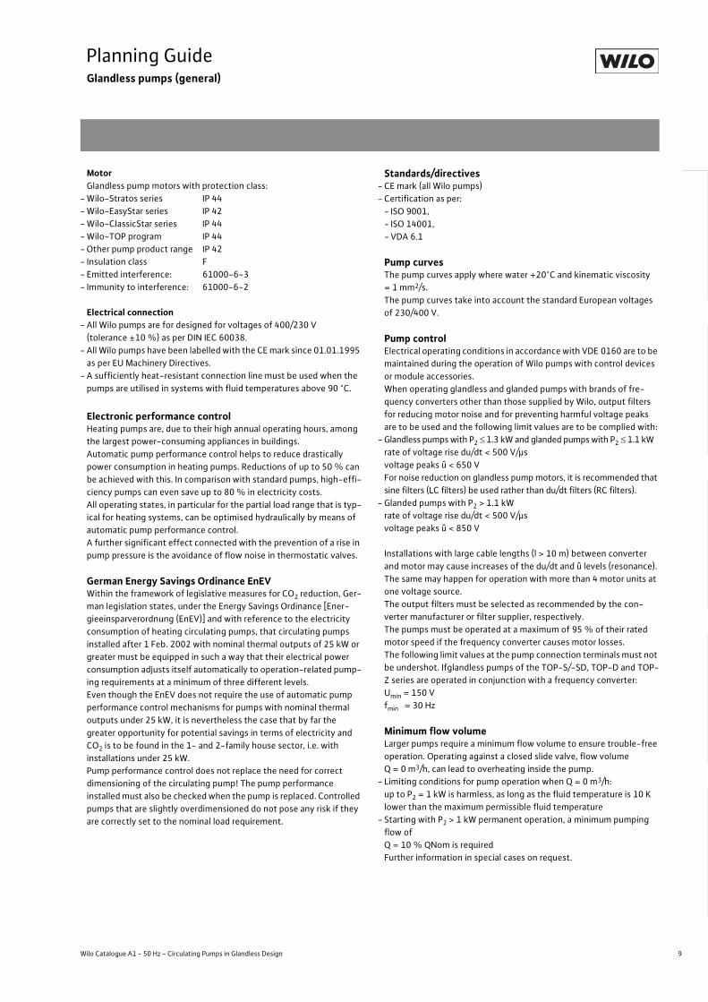
MotorGlandless pump motors with protection class:
- Wilo-Stratos series IP 44- Wilo-EasyStar series IP 42- Wilo-ClassicStar series IP 44- Wilo-TOP program IP 44- Other pump product range IP 42- Insulation class F- Emitted interference: 61000-6-3- Immunity to interference: 61000-6-2
Electrical connection- All Wilo pumps are for designed for voltages of 400/230 V
(tolerance ±10 %) as per DIN IEC 60038.- All Wilo pumps have been labelled with the CE mark since 01.01.1995
as per EU Machinery Directives.- A sufficiently heat-resistant connection line must be used when the
pumps are utilised in systems with fluid temperatures above 90 °C.
Electronic performance controlHeating pumps are, due to their high annual operating hours, among the largest power-consuming appliances in buildings.Automatic pump performance control helps to reduce drastically power consumption in heating pumps. Reductions of up to 50 % can be achieved with this. In comparison with standard pumps, high-effi-ciency pumps can even save up to 80 % in electricity costs.All operating states, in particular for the partial load range that is typ-ical for heating systems, can be optimised hydraulically by means of automatic pump performance control.A further significant effect connected with the prevention of a rise in pump pressure is the avoidance of flow noise in thermostatic valves.
German Energy Savings Ordinance EnEVWithin the framework of legislative measures for CO2 reduction, Ger-man legislation states, under the Energy Savings Ordinance [Ener-gieeinsparverordnung (EnEV)] and with reference to the electricity consumption of heating circulating pumps, that circulating pumps installed after 1 Feb. 2002 with nominal thermal outputs of 25 kW or greater must be equipped in such a way that their electrical power consumption adjusts itself automatically to operation-related pump-ing requirements at a minimum of three different levels.Even though the EnEV does not require the use of automatic pump performance control mechanisms for pumps with nominal thermal outputs under 25 kW, it is nevertheless the case that by far the greater opportunity for potential savings in terms of electricity and CO2 is to be found in the 1- and 2-family house sector, i.e. with installations under 25 kW.Pump performance control does not replace the need for correct dimensioning of the circulating pump! The pump performance installed must also be checked when the pump is replaced. Controlled pumps that are slightly overdimensioned do not pose any risk if they are correctly set to the nominal load requirement.
Standards/directives- CE mark (all Wilo pumps)- Certification as per:
- ISO 9001,- ISO 14001,- VDA 6.1
Pump curvesThe pump curves apply where water +20°C and kinematic viscosity = 1 mm2/s.The pump curves take into account the standard European voltages of 230/400 V.
Pump controlElectrical operating conditions in accordance with VDE 0160 are to be maintained during the operation of Wilo pumps with control devices or module accessories.When operating glandless and glanded pumps with brands of fre-quency converters other than those supplied by Wilo, output filters for reducing motor noise and for preventing harmful voltage peaks are to be used and the following limit values are to be complied with:
- Glandless pumps with P2 � 1.3 kW and glanded pumps with P2 � 1.1 kWrate of voltage rise du/dt < 500 V/�svoltage peaks û < 650 VFor noise reduction on glandless pump motors, it is recommended that sine filters (LC filters) be used rather than du/dt filters (RC filters).
- Glanded pumps with P2 > 1.1 kWrate of voltage rise du/dt < 500 V/�svoltage peaks û < 850 V
Installations with large cable lengths (l > 10 m) between converter and motor may cause increases of the du/dt and û levels (resonance). The same may happen for operation with more than 4 motor units at one voltage source.The output filters must be selected as recommended by the con-verter manufacturer or filter supplier, respectively.The pumps must be operated at a maximum of 95 % of their rated motor speed if the frequency converter causes motor losses.The following limit values at the pump connection terminals must not be undershot. Ifglandless pumps of the TOP-S/-SD, TOP-D and TOP-Z series are operated in conjunction with a frequency converter:Umin = 150 Vfmin = 30 Hz
Minimum flow volumeLarger pumps require a minimum flow volume to ensure trouble-free operation. Operating against a closed slide valve, flow volume Q = 0 m3/h, can lead to overheating inside the pump.
- Limiting conditions for pump operation when Q = 0 m3/h:up to P2 = 1 kW is harmless, as long as the fluid temperature is 10 K lower than the maximum permissible fluid temperature
- Starting with P2 > 1 kW permanent operation, a minimum pumping flow ofQ = 10 % QNom is requiredFurther information in special cases on request.

10 Subject to change without prior notice 09/2007 WILO AG
Planning GuideGlandless pumps (general)
Motor protectionService life and operational reliability of a circulating pump depend to a great extent on the choice of the correct motor protection device.Motor protection switches can no longer be justified for utilisation in conjunction with multi-speed pumps due to the fact that their motors demonstrate different rated currents in the various speed stages and this requires correspondingly different types of fuse protection.All circulating pumps are either
- blocking current-proof- provided with internal protection against unacceptably high winding
temperatures- with full motor protection through thermal winding contacts (WSK)
and separate Wilo relay (e.g. Wilo-SK 602/SK 622)- with full motor protection and integrated triggering mechanism
(Wilo-Stratos series, Wilo-TOP series, except TOP-D, see Pump data)No further onsite motor protection is required, except in cases where required by the EVU for blocking current-proof motors and motors with internal protection against unacceptably high winding tempera-tures.
Sound pressure levelThe construction of the glandless pumps is the reason for their low-noise operation. Its airborne noise values with measuring-surface sound pressure level Lp (A) [dB] depend on the motor power output and are determined under normal operating conditions.
Fig.: Sound pressure level of glandless pumps, determined as per DIN EN ISO 3745
Thermal insulation with heating applicationsAll Wilo-Stratos/Stratos-Z, Wilo-TOP-E/-S/-Z/-D and Stratos ECO single-head pumps are equipped as standard with insulation shells for the purpose of preventing thermal losses at the pump housing.Material: EPP, polypropylene foamThermal conductivity: 0.04 W/mK as per DIN 2612Flammability: class B2 as per DIN 4102; FMVSS 302When insulating the pump onsite, care must be taken to cover the pump up to the top edge of the pump housing only (the motor must be left uncovered).
Insulation for air-conditioning/cooling applicationsIf pumps from the following series
- Stratos, Stratos-D, Stratos-Z- TOP-S/-SD- TOP-D- TOP-Z- TOP-RL- SE/SE-TW
are utilised in air-conditioning/cooling applications, no vapour-proof insulation is permitted to cover the drain labyrinth between the pump housing and the motor, to ensure that any condensate having possi-bly accumulated in the motor can drain off freely through the con-densate drain openings in the motor housing.The Wilo-ClimaForm diffusion-proof insulation obtainable as acces-sory equipment for the Stratos, TOP-S, TOP-RL and SE series for the purpose of insulating pump housings in cold water applications ensures this automatically as a result of its specific construction.
Wilo-ClimaForm: - Water vapour diffusion resistance � � 7000- Normal flammability, as per DIN 4102-B2, Part 1- Quality-monitored as per DIN 18200
Quality and safety marks
For pump types:Star-E 25/ ..., -E 30/ ...,Stratos ECOStar-RS 25/ ..., -RS 30/ ...,RSD 30/ ..., Star-Z 20/1, -Z 25/6
Certificate of conformity/acceptance test certificateAvailable upon request at additional charge for all glandless circulat-ing pumps of the series
- Stratos, Stratos-D, Stratos-Z, Stratos-ZD- TOP-E/-ED- TOP-S/-SD- TOP-D- TOP-Z- TOP-RL- P/RP- DOP- SE/SE-TW- Certificate of conformity 2.1
Contents: Certification that the product supplied conforms to the order, without details of test results.
- Certificate of conformity 2.2Contents: Certification that the product supplied conforms to the order, with details of series test results.
- Inspection certificate 3.1BContents: Certification that the product supplied conforms to the order, with details of test results actually measured on the product.The required test procedure and scope must be specified with the order.
60
50
40
20
30
10
010 20 50 100 200 500 1000 2000 5000
WRate motor output P2
Lp (A) [dB], 2-pole standard pumps (max. 2900 1/min.) and Stratos seriesLp (A) [dB], 4-pole standard pumps (max. 1450 1/min.) and TOP-E series
3000
[dB]

11
Planning GuideGlandless pumps (general)
Wilo Catalogue A1 - 50 Hz - Circulating Pumps in Glandless Design
Hea
ting,
Air-
cond
ition
ing,
Co
olin
gSe
cond
ary
Hot W
ater
Circ
ulat
ion
Sola
r The
rmal
, Geo
ther
mal
En
ergy
Sys
tem
sSe
rvic
e/Ac
cess
orie
s, S
yste
ms
Switc
hgea
rs a
nd C
ontr
ol
Dev
ices
Pum
p M
anag
emen
t Sys
tem
s
1) Installation positions for Wilo-Stratos/-Stratos-Z/-Stratos-D/-Stratos-ZD see “Planning guide High-efficiency pumps”
Non-standard versionsPumps for other voltages or 60 Hz frequency possible on request (at additional charge).Other materials and design versions (RG, PN 16) for pumps are listed in the pump tables.
The glandless circulating pumpWith this design, all the rotating components inside the canned motor run in the pumped fluid. The required shaft sealing in conven-tional pump types accomplished through the use of stuffing boxes or mechanical seals is dispensed with. The pumped fluid lubricates the shaft bearings and cools the components from the electrical motor.The electrical part of the pump motor (stator with winding) is sepa-rated from the so-called encapsulated rotor compartment by means of an encapsulated motor cartridge (with the TOP-Wilo series) and/or by a can sealed off with O-rings.
Installation positions for glandless pumps1)
Installation positions not permitted
Permitted without limitationAll energy-saving pumps,
stageless control
Permitted without limitationAll standard and secondary hot water circulators,
1-, 3- or 4-speed stages
Additional terminal box positions for single-head and twin-head pumps
Pump types
Energy-saving pumpsStar-E 20 (25, 30) • – • –TOP-E 25 (30)/1-7TOP-E 30/1-10TOP-E 40/1-4TOP-E 50/1-6
• – • –
TOP-ED 32/1-7TOP-ED 40/1-7TOP-ED 50/1-6
• – – •
Standard and secondary hot water circulatorsStar-RS, Star-Z • • • •Stratos ECO-Z • – • –Star-RSD • • • •
Install pumps under voltage-free conditions. Valid for all operating conditions.TOP-ED twin-head pumps cannot be utilised for additional installation units because of the tilted alignment of the terminal boxes.If in doubt, please contact Wilo.
Impeller
Winding
Rotor
Bearings
Spacer can
Fluid
Hydraulic seal

12 Subject to change without prior notice 09/2007 WILO AG
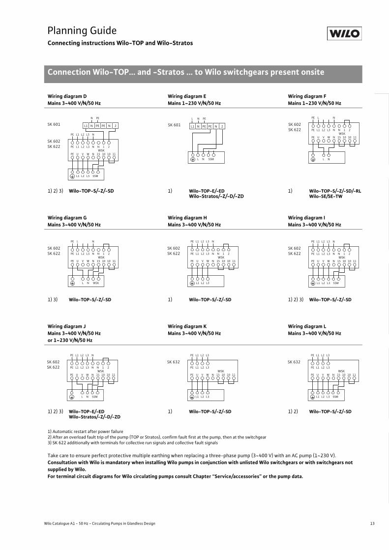
Planning GuideConnecting instructions Wilo-TOP and Wilo-Stratos
Connection Wilo-TOP... and -Stratos ... to Wilo switchgears present onsite
Connection Wilo-TOP... and -Stratos ... to Wilo switchgears present onsite
New pumptype Switchgear connection
possible as per circuit diagram
Accessories: Modules Wilo-IF-Module
Single-phase
AvailableWilo switchgear
Wilo-TOP-SWilo-TOP-Z
Wilo-TOP-RLWilo-SE
Wilo-TOP-SD Wilo-SE-TW
or2 x Wilo-TOP-S2 x Wilo-TOP-Z
2 x Wilo-TOP-RL2 x Wilo-SE
Wilo-TOP-D
Wilo-TOP-EStratos
Stratos-Z
Wilo-TOP-EDStratos-D
Stratos-ZDor
2 x TOP-E2 x Stratos
2 x Stratos-Z
Wilo-TOP-EStratos
Stratos-Z
Wilo-TOP-EDStratos-D
Stratos-ZD or2 x TOP-E2 x Stratos
2 x Stratos-Z
1~ 3~ 1~ 3~ 1~ 3~ 1~ 1~ 1~ 1~
IS WSKSSM IS SSM IS WSK
SSM IS SSM IS WSK IS WSK
SK 601 A B C 1) D 1) A B C 1) D 1) U W Y 1) Z E E Yes YesSK 602/622 F G H I F G H I V X Y1 Z1 J J Yes YesSK 632 – – K L – – K L – – K L – – Yes YesS2R 0.2-1
Switchgear not utilisable with Wilo-TOP series. Alternatively use exchange motor for faulty pump.S2R 2.5S2R 3D – – – – M N o P – – – – – Q or R Yes YesS4R 2.5
Switchgear not utilisable with Wilo-TOP series. Alternatively use exchange motor for faulty pump.S4R 2.5DAS 08/1.5(�P) – S – T – – – – – – – – – – – –2 Pcs.AS 08/1.5(�P) – – – – – S – T – – – – – – – –
08/1.5(�P)plus S2R 3D – – – – – N + S – P + T – – – – – – – –
AR/DR/CR – – – T – – – T – – – – – – – –
IS: Internal protection against unacceptably high winding temperatures, WSK: Thermal winding contacts, SSM: Collective fault signal
– = connection not possible, 1) Only in conjunction with contactor and/or Wilo-SK 602/622; SK602/622 also can be used as ON/OFF switch or contactor
Wiring diagram AMains 1~230 V/N/50 Hz
Wiring diagram BMains 1~230 V/N/50 Hz
Wiring diagram CMains 3~400 V/N/50 Hz
1) Wilo-TOP-S/-Z/-SD/-RLWilo-SE/SE-TW
1) 3) Wilo-TOP-S/-Z/-SD 1) 3) Wilo-TOP-S/-Z/-SD
1) Automatic restart after power failure2) After an overload fault trip of the pump (TOP or Stratos), confirm fault first at the pump, then at the switchgear3) SK 622 additionally with terminals for collective run signals and collective fault signals
Take care to ensure perfect protective multiple earthing when replacing a three-phase pump (3~400 V) with an AC pump (1~230 V).Consultation with Wilo is mandatory when installing Wilo pumps in conjunction with unlisted Wilo switchgears or with switchgears not supplied by Wilo.For terminal circuit diagrams for Wilo circulating pumps, consult Chapter “Service/accessories” or the pump data.
N
SK 601
NL PE
PE PEL1 N N 2
L
PE
PE
L1
U
L2
V
L3
W
N
PE L1 N
N
N
15
L N WSK
1
10
2
10 11WSK
SK 602SK 622
SK 601
N PE
PE PEL1 N N 2
PE
PE
L1
U
L2
V
L3
W
N
PE L1 L2 L3 N
N
N
15
L2L1 L3
1
10
2
10 11WSK
SK 602SK 622
SK 601
N PE
PE PEL1 N N 2
13
Planning GuideConnecting instructions Wilo-TOP and Wilo-Stratos
Connection Wilo-TOP... and -Stratos ... to Wilo switchgears present onsite
Wilo Catalogue A1 - 50 Hz - Circulating Pumps in Glandless Design
Hea
ting,
Air-
cond
ition
ing,
Co
olin
gSe
cond
ary
Hot W
ater
Circ
ulat
ion
Sola
r The
rmal
, Geo
ther
mal
En
ergy
Sys
tem
sSe
rvic
e/Ac
cess
orie
s, S
yste
ms
Switc
hgea
rs a
nd C
ontr
ol
Dev
ices
Pum
p M
anag
emen
t Sys
tem
s
Wiring diagram DMains 3~400 V/N/50 Hz
Wiring diagram EMains 1~230 V/N/50 Hz
Wiring diagram FMains 1~230 V/N/50 Hz
1) 2) 3) Wilo-TOP-S/-Z/-SD 1) Wilo-TOP-E/-EDWilo-Stratos/-Z/-D/-ZD
1) Wilo-TOP-S/-Z/-SD/-RLWilo-SE/SE-TW
Wiring diagram GMains 3~400 V/N/50 Hz
Wiring diagram HMains 3~400 V/N/50 Hz
Wiring diagram IMains 3~400 V/N/50 Hz
1) 3) Wilo-TOP-S/-Z/-SD 1) Wilo-TOP-S/-Z/-SD 1) 2) 3) Wilo-TOP-S/-Z/-SD
Wiring diagram JMains 3~400 V/N/50 Hz or 1~230 V/N/50 Hz
Wiring diagram KMains 3~400 V/N/50 Hz
Wiring diagram LMains 3~400 V/N/50 Hz
1) 2) 3) Wilo-TOP-E/-EDWilo-Stratos/-Z/-D/-ZD
1) Wilo-TOP-S/-Z/-SD 1) 2) Wilo-TOP-S/-Z/-SD
1) Automatic restart after power failure2) After an overload fault trip of the pump (TOP or Stratos), confirm fault first at the pump, then at the switchgear3) SK 622 additionally with terminals for collective run signals and collective fault signals
Take care to ensure perfect protective multiple earthing when replacing a three-phase pump (3~400 V) with an AC pump (1~230 V).Consultation with Wilo is mandatory when installing Wilo pumps in conjunction with unlisted Wilo switchgears or with switchgears not supplied by Wilo.For terminal circuit diagrams for Wilo circulating pumps consult Chapter “Service/accessories” or the pump data.
PE
PE
L1
U
L2
V
L3
W
N
PE L1 L2 L3 N
N
N
15
L2L1 L3 SSM
1
10
2
10 11WSK
SK 602SK 622
SK 601
N PE
PE PEL1 N N 2
N
SK 601
NL PE
PE PEL1 N N 2
L SSM
PE
PE
L1
U
L2
V
L3
W
N
PE L N
N
N
15
L N
1
10
2
10 11WSK
SK 602SK 622
PE
PE
L1
U
L2
V
L3
W
N
PE L N
N
N
15
1
10
2
10 11WSK
SK 602SK 622
L N WSK
PE
PE
L1
U
L2
V
L3
W
N
PE L1 L2 L3 N
N
N
15
L2L1 L3
1
10
2
10 11WSK
SK 602SK 622 PE
PE
L1
U
L2
V
L3
W
N
PE L1 L2 L3 N
N
N
15
L2L1 L3 SSM
1
10
2
10 11WSK
SK 602SK 622
PE
PE
L1
U
L2
V
L3
W
N
PE L1 L2 L3 N
N
N
15
L N SSM
1
10
2
10 11WSK
SK 602SK 622 PE
PE
L1
U
L2
V
L3
W
PE L1 L2 L3
N 15
L2 L3L1
10 10 11WSK
SK 632PE
PE
L1
U
L2
V
L3
W
PE L1 L2 L3
N 15
L2 L3L1
10 10 11WSK
SK 632
SSM
14 Subject to change without prior notice 09/2007 WILO AG
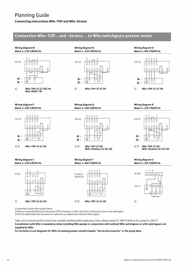
Planning GuideConnecting instructions Wilo-TOP and Wilo-Stratos
Connection Wilo-TOP... and -Stratos ... to Wilo switchgears present onsite
Wiring diagram MMains 1~230 V/N/50 Hz
Wiring diagram NMains 1~230 V/N/50 Hz
Wiring diagram OMains 3~400 V/N/50 Hz
1) Wilo-TOP-S/-Z/-SD/-RLWilo-SE/SE-TW
1) Wilo-TOP-S/-Z/-SD 1) Wilo-TOP-S/-Z/-SD
Wiring diagram PMains 3~400 V/N/50 Hz
Wiring diagram QMains 3~400 V/N/50 Hz
Wiring diagram RMains 1~230 V/N/50 Hz
1) 2) Wilo-TOP-S/-Z/-SD 1) 2) Wilo-TOP-E/-EDWilo-Stratos/-Z/-D/-ZD
1) 2) Wilo-TOP-E/-EDWilo-Stratos/-Z/-D/-ZD
Wiring diagram SMains 1~230 V/N/50 Hz
Wiring diagram TMains 3~400 V/N/50 Hz
Wiring diagram UMains 1~230 V/N/50 Hz
1) Wilo-TOP-S/-Z/-SD 1) 2) Wilo-TOP-S/-Z/-SD 1)
1) Automatic restart after power failure2) After an overload fault trip of the pump (TOP or Stratos), confirm fault first at the pump, then at the switchgear3) SK 622 additionally with terminals for collective run signals and collective fault signals
Take care to ensure perfect protective multiple earthing when replacing a three-phase pump (3~400 V) with an AC pump (1~230 V).Consultation with Wilo is mandatory when installing Wilo pumps in conjunction with unlisted Wilo switchgears or with switchgears not supplied by Wilo.For terminal circuit diagrams for Wilo circulating pumps consult Chapter “Service/accessories” or the pump data.
PE
PE
L1
U
L2
V
L3
W
N
PE L N
N 15
L N
10 11 WSK
S2R 3D
1
2
PE
PE
L1
U
L2
V
L3
W
N
PE L N
N 15
L N WSK
10 11WSK
S2R 3D
1
2
PE
PE
L1
U
L2
V
L3
W
PE L1 L2 L3
N 15
L2 L3L1
10 11WSK
S2R 3D
1
2
N
N
PE
PE
L1
U
L2
V
L3
W
PE L1 L2 L3
N 15
L2 L3L1 SSM
10 11WSK
S2R 3D
1
2
N
N
PE
PE
L1
U
L2
V
L3
W
PE L1 L2 L3
N 15
NL1 SSM
10 11WSK
S2R 3D
1
2
N
N
PE
PE
L1
U
L2
V
L3
W
PE L1
N 15
NL1 SSM
10 11WSK
S2R 3D
1
2
N
N
PE
PE
L1
U
L2
V
L3
W
PE L
N 15 10 WSK
AS 08N
N
N L WSK/SSM
PE
PE
L1
U
L2
V
L3
W
PE L1 L2 L3
N 15
L3L1 L3 SSM
10WSK
AS 08/1,5AR/DR/CR N
N
SK 601
TOP-D
NL1 PE
PE PEL1 N N 2
U1 V1 W1
W2 U2 V2

15
Planning GuideConnecting instructions Wilo-TOP and Wilo-Stratos
Connection Wilo-TOP... and -Stratos ... to Wilo switchgears present onsite
Wilo Catalogue A1 - 50 Hz - Circulating Pumps in Glandless Design
Hea
ting,
Air-
cond
ition
ing,
Co
olin
gSe
cond
ary
Hot W
ater
Circ
ulat
ion
Sola
r The
rmal
, Geo
ther
mal
En
ergy
Sys
tem
sSe
rvic
e/Ac
cess
orie
s, S
yste
ms
Switc
hgea
rs a
nd C
ontr
ol
Dev
ices
Pum
p M
anag
emen
t Sys
tem
s
1) Automatic restart after power failure2) After an overload fault trip of the pump (TOP or Stratos), confirm fault first at the pump, then at the switchgear3) SK 622 additionally with terminals for collective run signals and collective fault signals
Take care to ensure perfect protective multiple earthing when replacing a three-phase pump (3~400 V) with an AC pump (1~230 V).Consultation with Wilo is mandatory when installing Wilo pumps in conjunction with unlisted Wilo switchgears or with switchgears not supplied by Wilo.For terminal circuit diagrams for Wilo circulating pumps consult Chapter “Service/accessories” or the pump data.
Wiring diagram VMains 1~230 V/N/50 Hz
Wiring diagram WMains 1~230 V/N/50 Hz
Wiring diagram XMains 1~230 V/N/50 Hz
1) 1) 3) 1) 3)
Wiring diagram YMains 3~400 V/N/50 Hz
Wiring diagram Y1Mains 3~400 V/N/50 Hz
Wiring diagram ZMains 3~400 V/N/50 Hz
1) 3) 1) 1) 3)
Wiring diagram Z1Mains 3~400 V/N/50 Hz
1) 3)
TOP-D U1 V1 W1
W2 U2 V2
PE
PE
L1
U
L2
V
L3
W
N
PE L1 N
N
N
15
1
10
2
10 11WSK
SK 602SK 622
TOP-D U1 V1 W1
W2 U2 V2
PE
PE
L1
U
L2
V
L3
W
N
PE L1 N
N
N
15
1
10
2
15 10
10 11WSK
WSK
SK 602SK 622
SK 601
N PE
PE PEL1 N N 2
TOP-D U1 V1 W1
W2 U2 V2
PE
PE
L1
U
L2
V
L3
W
N
PE L1 N
N
N
15
1
10
2
15 10
10 11WSK
WSK
SK 602SK 622
TOP-D U1 V1 W1
W2 U2 V2
PE
PE
L1
U
L2
V
L3
W
N
PE L1 N
N
N
15
1
10
2
10 11WSK
SK 602SK 622
L2 L3
SK 601
N PE
PE PEL1 N N 2
TOP-D U1 V1 W1
W2 U2 V2
PE
PE
L1
U
L2
V
L3
W
N
PE L1 N
N
N
15
1
10
2
10 11WSK
SK 602SK 622
L2 L3
PE
PE
L1
U
L2
V
L3
W
N
PE L1 N
N
N
15
1
10
2
15 10
10 11WSK
WSK
SK 602SK 622
L2 L3
SK 601
N PE
PE PEL1 N N 2
TOP-D U1 V1 W1
W2 U2 V2
PE
PE
L1
U
L2
V
L3
W
N
PE L1 N
N
N
15
1
10
2
15 10
10 11WSK
WSK
SK 602SK 622
L2 L3
TOP-D U1 V1 W1
W2 U2 V2
16 Subject to change without prior notice 09/2007 WILO AG
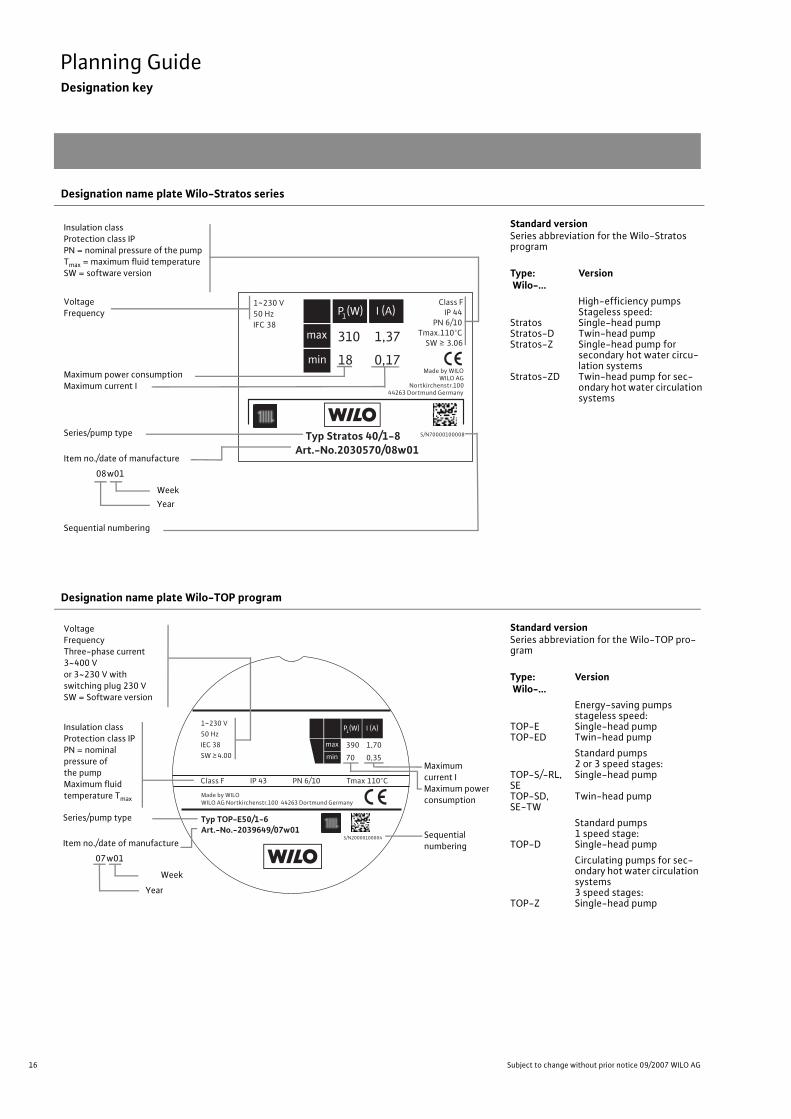
Planning GuideDesignation key
Designation name plate Wilo-Stratos series
Standard versionSeries abbreviation for the Wilo-Stratos program
Type: Wilo-...
Version
StratosStratos-DStratos-Z
Stratos-ZD
High-efficiency pumpsStageless speed:Single-head pumpTwin-head pumpSingle-head pump for secondary hot water circu-lation systemsTwin-head pump for sec-ondary hot water circulation systems
Designation name plate Wilo-TOP program
Standard versionSeries abbreviation for the Wilo-TOP pro-gram
Type: Wilo-...
Version
TOP-ETOP-ED
Energy-saving pumpsstageless speed:Single-head pumpTwin-head pump
TOP-S/-RL, SETOP-SD, SE-TW
Standard pumps2 or 3 speed stages:Single-head pump
Twin-head pump
TOP-D
Standard pumps1 speed stage:Single-head pump
TOP-Z
Circulating pumps for sec-ondary hot water circulation systems3 speed stages:Single-head pump
Typ Stratos 40/1-8Art.-No.2030570/08w01
1~230 V50 HzIFC 38
Class F IP 44 PN 6/10Tmax.110°C SW 3.06
Made by WILO WILO AG Nortkirchenstr.10044263 Dortmund Germany
S/N70000100008
310 1,37
18 0,17
Insulation classProtection class IPPN = nominal pressure of the pumpTmax = maximum fluid temperatureSW = software version
VoltageFrequency
Maximum power consumptionMaximum current I
Series/pump type
Item no./date of manufacture
08w01
Week Year
Sequential numbering
Typ TOP-E50/1-6Art.-No.-2039649/07w01
1~230 V50 HzIEC 38SW 4.00
Made by WILOWILO AG Nortkirchenstr.100 44263 Dortmund Germany
Class F IP 43
S/N20000100004
PN 6/10 Tmax 110°C
390 1,70
70 0,35
Insulation classProtection class IPPN = nominal pressure of the pumpMaximum fluid temperature Tmax
VoltageFrequencyThree-phase current 3~400 V or 3~230 V with switching plug 230 VSW = Software version
Maximum current IMaximum power consumption
Series/pump type
Item no./date of manufacture
07w01
Week Year
Sequential numbering

17
Planning GuideDesignation key
Wilo Catalogue A1 - 50 Hz - Circulating Pumps in Glandless Design
Hea
ting,
Air-
cond
ition
ing,
Co
olin
gSe
cond
ary
Hot W
ater
Circ
ulat
ion
Sola
r The
rmal
, Geo
ther
mal
En
ergy
Sys
tem
sSe
rvic
e/Ac
cess
orie
s, S
yste
ms
Switc
hgea
rs a
nd C
ontr
ol
Dev
ices
Pum
p M
anag
emen
t Sys
tem
s
Non-standard versionsSeveral pumps can be supplied in the following non-standard versions at additional charge, if desired (the type of the special version is marked on the name plate):
- 130 Pump with short over-all length 130 mm- RG Red brass version
Example:Star-RS 25/4 RG = Star-RS 25/4 with red brass housing
Designation name plate Wilo-Stratos ECO, Wilo-Star
Standard versionSeries abbreviations for the programmes Wilo-Star and Wilo-Stratos ECO.Type: Wilo-...
Version
Stratos ECOStratos ECO-L
High-efficiency pumpsStageless speed:Single-head pump Ventilation pump
Star-E
Energy-saving pumpsstageless speed:Single-head pump
Star-RSStar-RSDStar-RSL
Standard pumps3 speed stages:Single-head pumpTwin-head pumpVentilation pumpSecondary hot water cir-culators:
Stratos ECO-Z Single-head pump in high-efficiency construc-tion for secondary hot water circulation systems
Star-Z Single-head pumps, 1 or 3 speed stagesSolar thermal pumps:
Stratos ECO-ST Single-head pump, high-efficiency version for solar thermal systems
Star ST Single-head pumps,3 speed stages for solar thermal systems
Star-RSG Single-head pumps,3 speed stages for geo-thermal systems
Art.-No. 4092510/07w01Stratos ECO 25/1-5
1 ~ 230 V50 Hz5,8-59 WImax 0,46 APN 10TF 110IP 44
WILO AGNortkirchenstr.100 44263 Dortmund Germany
VoltageFrequencyPower consumptionMaximum current IPressure stage PNMaximum fluid temperature TmaxProtection class
Series/pump type
Item no./date of manufacture
07w01
Week
Year
18 Subject to change without prior notice 09/2007 WILO AG
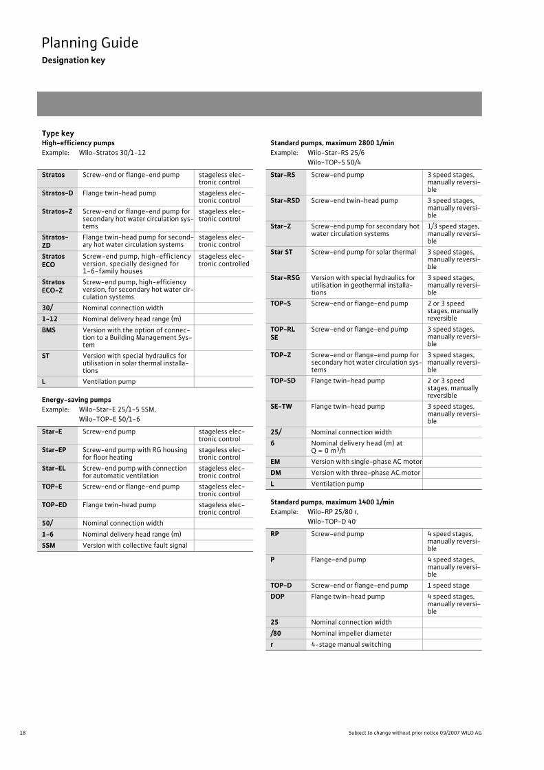
Planning GuideDesignation key
Type keyHigh-efficiency pumpsExample: Wilo-Stratos 30/1-12
Energy-saving pumpsExample: Wilo-Star-E 25/1-5 SSM,
Wilo-TOP-E 50/1-6
Standard pumps, maximum 2800 1/minExample: Wilo-Star-RS 25/6
Wilo-TOP-S 50/4
Standard pumps, maximum 1400 1/minExample: Wilo-RP 25/80 r,
Wilo-TOP-D 40
Stratos Screw-end or flange-end pump stageless elec-tronic control
Stratos-D Flange twin-head pump stageless elec-tronic control
Stratos-Z Screw-end or flange-end pump for secondary hot water circulation sys-tems
stageless elec-tronic control
Stratos-ZD
Flange twin-head pump for second-ary hot water circulation systems
stageless elec-tronic control
Stratos ECO
Screw-end pump, high-efficiency version, specially designed for 1-6-family houses
stageless elec-tronic controlled
Stratos ECO-Z
Screw-end pump, high-efficiency version, for secondary hot water cir-culation systems
30/ Nominal connection width1-12 Nominal delivery head range (m)BMS Version with the option of connec-
tion to a Building Management Sys-tem
ST Version with special hydraulics for utilisation in solar thermal installa-tions
L Ventilation pump
Star-E Screw-end pump stageless elec-tronic control
Star-EP Screw-end pump with RG housing for floor heating
stageless elec-tronic control
Star-EL Screw-end pump with connection for automatic ventilation
stageless elec-tronic control
TOP-E Screw-end or flange-end pump stageless elec-tronic control
TOP-ED Flange twin-head pump stageless elec-tronic control
50/ Nominal connection width1-6 Nominal delivery head range (m)SSM Version with collective fault signal
Star-RS Screw-end pump 3 speed stages, manually reversi-ble
Star-RSD Screw-end twin-head pump 3 speed stages, manually reversi-ble
Star-Z Screw-end pump for secondary hot water circulation systems
1/3 speed stages, manually reversi-ble
Star ST Screw-end pump for solar thermal 3 speed stages, manually reversi-ble
Star-RSG Version with special hydraulics for utilisation in geothermal installa-tions
3 speed stages, manually reversi-ble
TOP-S Screw-end or flange-end pump 2 or 3 speed stages, manually reversible
TOP-RL SE
Screw-end or flange-end pump 3 speed stages, manually reversi-ble
TOP-Z Screw-end or flange-end pump for secondary hot water circulation sys-tems
3 speed stages, manually reversi-ble
TOP-SD Flange twin-head pump 2 or 3 speed stages, manually reversible
SE-TW Flange twin-head pump 3 speed stages, manually reversi-ble
25/ Nominal connection width6 Nominal delivery head (m) at
Q = 0 m3/hEM Version with single-phase AC motorDM Version with three-phase AC motorL Ventilation pump
RP Screw-end pump 4 speed stages, manually reversi-ble
P Flange-end pump 4 speed stages, manually reversi-ble
TOP-D Screw-end or flange-end pump 1 speed stageDOP Flange twin-head pump 4 speed stages,
manually reversi-ble
25 Nominal connection width/80 Nominal impeller diameterr 4-stage manual switching

19
Planning GuideEnergy efficiency classification
Wilo Catalogue A1 - 50 Hz - Circulating Pumps in Glandless Design
Hea
ting,
Air-
cond
ition
ing,
Co
olin
gSe
cond
ary
Hot W
ater
Circ
ulat
ion
Sola
r The
rmal
, Geo
ther
mal
En
ergy
Sys
tem
sSe
rvic
e/Ac
cess
orie
s, S
yste
ms
Switc
hgea
rs a
nd C
ontr
ol
Dev
ices
Pum
p M
anag
emen
t Sys
tem
s
Energy efficiency classification
Under the auspices of the Kyoto Agreement, the European govern-ments in particular are pursuing the goal of drastically reducing CO2-emissions. Energy-specific designations, particularly for high-consumption household devices such as washing machines and refrigerators, is prescribed as an important control element for pro-viding the end consumer with an aid for making decisions in favour of energy-saving appliances.Because of the fact that heating circulating pumps are numbered among the biggest energy consumers in household use because of their long running times, leading European heating pump manufac-turers have voluntarily declared their intention of henceforth attach-ing energy consumption labels to their heating pumps. This makes it possible for users and end consumers to recognise, on the basis of an already familiar classification system, whether a heating circulating pump being utilised is especially energy-efficient.The classification of the energy efficiency of heating pumps is carried out by means of a monitoring procedure which yields the Energy Effi-ciency Index EEI. The smaller the EEI, the less electrical energy the pump consumes and the more favourable the energy classification.
Tab.: Breakdown of the Energy Efficiency Index into 7 different energy classes
The following tables identify the associated energy class for all the heating pumps to be labelled, which can be seen to be incorporated into the energy label on the packaging. In accordance with the letter-ing system familiar from household appliances, A is the best possible and G is the worst possible of the energy classes.A comparison of hydraulically similar pumps with different energy classifications reveals that there is a difference of approximately 22 percentage points in terms of energy expenditure between two sequentially numbered energy classes. Accordingly, an energy class A pump requires on average only around 33 % of the electrical energy used by a class D pump.Even though the energy-related requirements of a class A pump are very high, high-efficiency energy class A pumps have in the mean-time become available for utilisation throughout the entire perform-ance range that runs from single-family houses to large buildings.
Fig.: Comparison of the energy consumption rates of pumps with the same hydraulic output
Fig.: Energy label for heating circulating pumps,example: energy class A
Energy Class Energy Efficiency Index
A EEI <0.4
B 0.4 � EEI < 0.6
C 0.6 � EEI < 0.8
D 0.8 � EEI < 1.0
E 1.0 � EEI < 1.2
F 1.2 � EEI < 1.4
G 1.4 � EEI
0%
20%
40%
60%
80%
100%
120%
140%
160%
180%
A B C D E F G
Energy class
Rela
tive
pow
er c
onsu
mpt
ion

20 Subject to change without prior notice 09/2007 WILO AG
Planning GuideEEI classifications
EEI classification – Single-head pumps/ twin-head pumps (area of application: single-family and two-family houses)
Nominal diameter
Wilo-Stratos ... EEI class
Wilo-Star-E...(EasyStar)
EEI-class
Wilo-Smart... EEI-class
Wilo-Star-RS...(ClassicStar)
EEI-class
Wilo-Star-RSD...(ClassicStar)
EEI-class
DN 15 (Rp ½) – – 15/1-3 – – – 15/4 B – –– – 15/1-5 – – – 15/6 C – –
DN 25 (Rp 1) 25/1-3 A 25/1-3 B 25/4 B 25/2 C – –25/1-5 A 25/1-5 B 25/6 B 25/4 B – –
– – – – – – 25/6 C – –– – – – – – 25/7 D – –– – – – – – 25/8 D – –
DN 30 (Rp 1 ¼) 30/1-3 A 30/1-3 B – – 30/2 C – –30/1-5 A 30/1-5 B 30/4 B 30/4 B 30/4 D
– – – – 30/6 B 30/6 C 30/6 D– – – – 30/7 D– – – – 30/8 D
EEI classification – Single-head pumps (range of applications: multi-family houses, commercial applications)
Nominal diameter
Wilo-Stratos... EEI class
Wilo-TOP-E... EEI class
Wilo-TOP-S... EEI class
Wilo-RP/P... EEI class
DN 25 (Rp 1) 25/1-6 A 25/1-7 C 25/5 EM/DM D/D RP 25/80 r EM/DM G/G25/1-8 A – – 25/7 EM/DM D/D RP 25/100 r EM/DM F/E
– – – – 25/10 EM/DM D/D – –– – – – 25/13 EM/DM F/F – –
DN 30 (Rp 1 ¼) 30/1-6 A 30/1-7 C 30/4 EM/DM D/D RP 30/80 r EM/DM G/F30/1-8 A 30/1-10 C 30/5 EM/DM D/D RP 30/100 r EM/DM F/F
30/1-12 A – – 30/7 EM/DM D/D – –– – – 30/10 EM/DM D/D – –
DN 32 32/1-12 A – – – – – –DN 40 40/1-4 A 40/1-4 C 40/4 EM/DM D/D P 40/100 r EM/DM F/D
40/1-8 A 40/1-10 B 40/7 EM/DM D/C P 40/160 r E40/1-12 A – – 40/10 EM/DM D/C – –
– – – – 40/15 EM/DM D/D – –DN 50 50/1-8 A 50/1-6 C 50/4 EM/DM D/D P 50/125 r D
50/1-9 A 50/1-7 B 50/7 EM/DM E/C P 50/160 r E50/1-12 A 50/1-10 B 50/10 EM/DM D/C P 50/250 r E
– – – – 50/15 C – –DN 65 65/1-9 A 65/1-10 B 65/7 EM/DM F/D P 65/125 r D
65/1-12 A – – 65/10 EM/DM F/D P 65/160 r D– – – – 65/13 C P 65/250 r E– – – – 65/15 C – –
DN 80 80/1-12 A 80/1-10 B 80/7 EM/DM F/D P 80/125 r D– – – – 80/10 D P 80/160 r C– – – – – – P 80/250 r E
DN 100 100/1-12 A 100/1-10 B 100/10 D P 100/160 r E– – – – – – P 100/200 r E
21
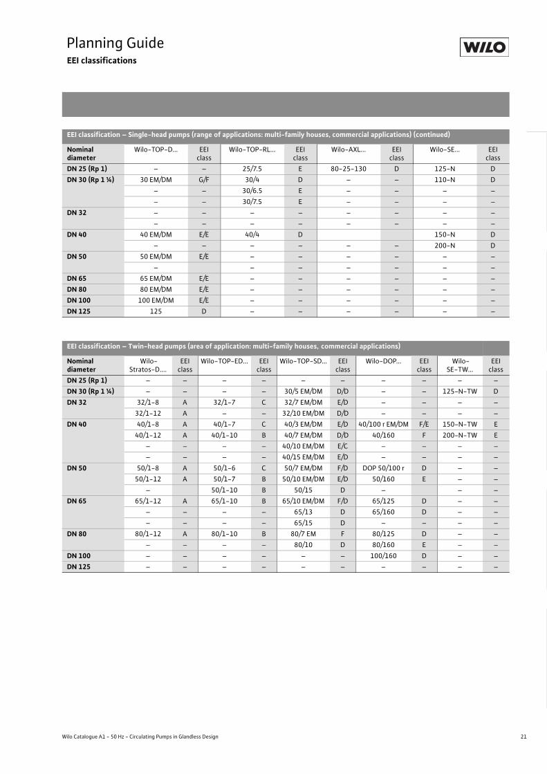
Planning GuideEEI classifications
Wilo Catalogue A1 - 50 Hz - Circulating Pumps in Glandless Design
Hea
ting,
Air-
cond
ition
ing,
Co
olin
gSe
cond
ary
Hot W
ater
Circ
ulat
ion
Sola
r The
rmal
, Geo
ther
mal
En
ergy
Sys
tem
sSe
rvic
e/Ac
cess
orie
s, S
yste
ms
Switc
hgea
rs a
nd C
ontr
ol
Dev
ices
Pum
p M
anag
emen
t Sys
tem
s
EEI classification – Single-head pumps (range of applications: multi-family houses, commercial applications) (continued)
Nominal diameter
Wilo-TOP-D... EEI class
Wilo-TOP-RL... EEI class
Wilo-AXL... EEI class
Wilo-SE... EEI class
DN 25 (Rp 1) – – 25/7.5 E 80-25-130 D 125-N DDN 30 (Rp 1 ¼) 30 EM/DM G/F 30/4 D – – 110-N D
– – 30/6.5 E – – – –– – 30/7.5 E – – – –
DN 32 – – – – – – – –– – – – – – – –
DN 40 40 EM/DM E/E 40/4 D 150-N D– – – – – – 200-N D
DN 50 50 EM/DM E/E – – – – – –– – – – – – –
DN 65 65 EM/DM E/E – – – – – –DN 80 80 EM/DM E/E – – – – – –DN 100 100 EM/DM E/E – – – – – –DN 125 125 D – – – – – –
EEI classification – Twin-head pumps (area of application: multi-family houses, commercial applications)
Nominal diameter
Wilo-Stratos-D....
EEI class
Wilo-TOP-ED... EEI class
Wilo-TOP-SD... EEI class
Wilo-DOP... EEI class
Wilo-SE-TW...
EEI class
DN 25 (Rp 1) – – – – – – – – – –DN 30 (Rp 1 ¼) – – – – 30/5 EM/DM D/D – – 125-N-TW DDN 32 32/1-8 A 32/1-7 C 32/7 EM/DM E/D – – – –
32/1-12 A – – 32/10 EM/DM D/D – – – –DN 40 40/1-8 A 40/1-7 C 40/3 EM/DM E/D 40/100 r EM/DM F/E 150-N-TW E
40/1-12 A 40/1-10 B 40/7 EM/DM D/D 40/160 F 200-N-TW E– – – – 40/10 EM/DM E/C – – – –– – – – 40/15 EM/DM E/D – – – –
DN 50 50/1-8 A 50/1-6 C 50/7 EM/DM F/D DOP 50/100 r D – –50/1-12 A 50/1-7 B 50/10 EM/DM E/D 50/160 E – –
– 50/1-10 B 50/15 D – – –DN 65 65/1-12 A 65/1-10 B 65/10 EM/DM F/D 65/125 D – –
– – – – 65/13 D 65/160 D – –– – – – 65/15 D – – – –
DN 80 80/1-12 A 80/1-10 B 80/7 EM F 80/125 D – –– – – – 80/10 D 80/160 E – –
DN 100 – – – – – – 100/160 D – –DN 125 – – – – – – – – – –
22 Subject to change without prior notice 09/2007 WILO AG
Planning GuideHigh-efficiency pumps
Wilo-Stratos/Stratos-Z/Stratos-D/Stratos-ZD
Planning guide:Wilo-Stratos/Stratos-Z/Stratos-D/Stratos-ZDWilo-Stratos is the first high-efficiency pump in the world to exhibit the following advantages as a glandless pump:
- Electricity savings of up to 80 % compared with standard pumps- For all heating, air-conditioning and cooling systems in the tempera-
ture range of -10 °C to +110 °C- Automatic adjustment of pump performance to continually changing
hydraulic system load conditions- Preventing flow noise- Reliability and comfort during installation and operation
Fields of applicationThe Wilo-Stratos series is utilised as a high-efficiency pump in circu-lation systems for heating, ventilation and air-conditioning systems in commercial residential and functional construction:
- Large residential buildings- Apartment blocks- Residential complexes- Hospitals- Schools- Administrative office buildings- Real-estate developments
Temperature rangeFluid temperature range from -10 °C to +110 °C without to for ambi-ent temperatures for from -10 °C to a maximum of +40 °C.
Heating applicationIn nearly all circulation systems, correctly sized controlled glandless pumps ensure adequate heat supply at all times at significantly reduced energy costs, while at the same time preventing noise gen-eration.Controlled heating circulating pumps have been mandated by law under the German Energy Savings Ordinance [Energieeinspar-verordnung (EnEV)] for 25 kW nominal thermal output and greater since 01.01.2002.Because of its corrosion-resistant pump housing made of red brass, the Wilo-Stratos-Z is particularly suitable for installations with possi-ble oxygen entry such as floor heating systems constructed of plastic tubing.
Thermal insulation for heatingThe Wilo-Stratos/-Stratos-Z single-head pump series are equipped as standard with a thermal insulation shell for the prevention of heat losses through the pump housing. The PP material used, foamed polypropylene, has the following properties:
- Environmental compatibility: easily recyclable- Thermal resistance: up to 120 °C- Transmission coefficient: 0.04 W/mK as per DIN 52612- Flammability: class B2 as per DIN 4102 (normal flammability)
Normally flammable materials are permitted to be utilised in heating areas in Germany in accordance with fire prevention regulations as long as a minimum clearance of 20 cm is maintained between them and the fireplace.
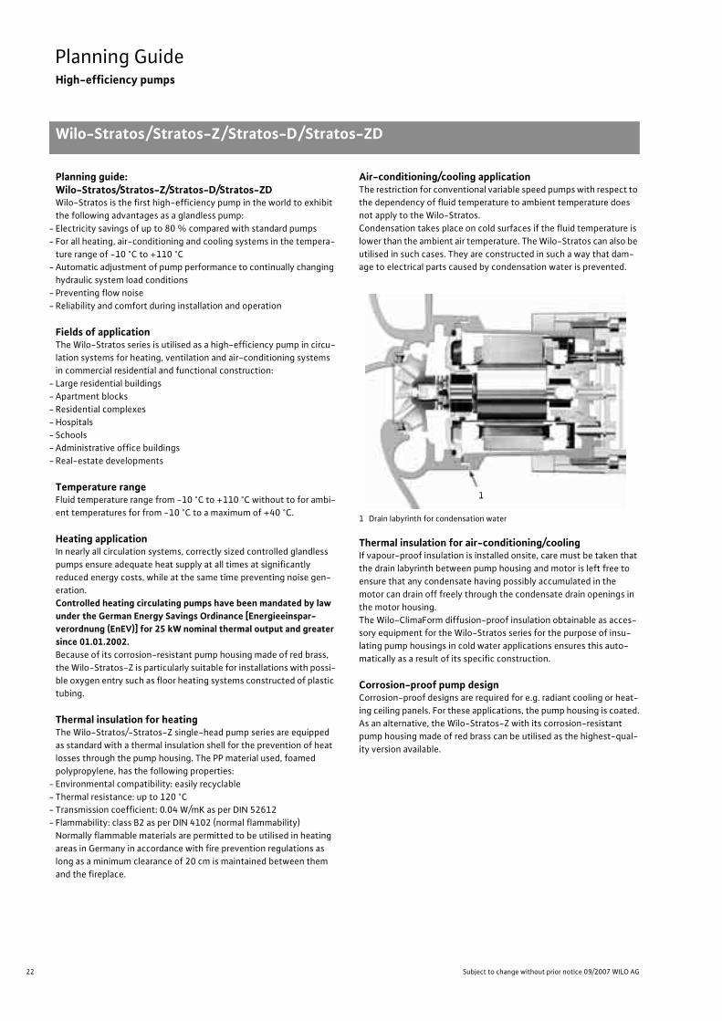
Air-conditioning/cooling applicationThe restriction for conventional variable speed pumps with respect to the dependency of fluid temperature to ambient temperature does not apply to the Wilo-Stratos.Condensation takes place on cold surfaces if the fluid temperature is lower than the ambient air temperature. The Wilo-Stratos can also be utilised in such cases. They are constructed in such a way that dam-age to electrical parts caused by condensation water is prevented.
1 Drain labyrinth for condensation water
Thermal insulation for air-conditioning/coolingIf vapour-proof insulation is installed onsite, care must be taken that the drain labyrinth between pump housing and motor is left free to ensure that any condensate having possibly accumulated in the motor can drain off freely through the condensate drain openings in the motor housing.The Wilo-ClimaForm diffusion-proof insulation obtainable as acces-sory equipment for the Wilo-Stratos series for the purpose of insu-lating pump housings in cold water applications ensures this auto-matically as a result of its specific construction.
Corrosion-proof pump designCorrosion-proof designs are required for e.g. radiant cooling or heat-ing ceiling panels. For these applications, the pump housing is coated.As an alternative, the Wilo-Stratos-Z with its corrosion-resistant pump housing made of red brass can be utilised as the highest-qual-ity version available.
1

23
Planning GuideHigh-efficiency pumps
Wilo-Stratos/Stratos-Z/Stratos-D/Stratos-ZD
Wilo Catalogue A1 - 50 Hz - Circulating Pumps in Glandless Design
Hea
ting,
Air-
cond
ition
ing,
Co
olin
gSe
cond
ary
Hot W
ater
Circ
ulat
ion
Sola
r The
rmal
, Geo
ther
mal
En
ergy
Sys
tem
sSe
rvic
e/Ac
cess
orie
s, S
yste
ms
Switc
hgea
rs a
nd C
ontr
ol
Dev
ices
Pum
p M
anag
emen
t Sys
tem
s
Applications for secondary hot water circulation (Wilo-Stratos-Z/Stratos-ZD)Pumps which are utilised in secondary hot water circulation systems are subject to specific requirements that are fulfilled by the Wilo-Stratos-Z/Stratos-ZD series:
- Fluids are secondary hot water and water for food businesses as per TrinkwV 2001. The formation of calcium deposits has been taken into account in the structural design, so that a total carbonate hardness of 20°d is authorised for a maximum fluids temperature of +80 °C.
- All plastic parts that come into contact with the pumped liquid are in conformance with KTW recommendations.
- The differential pressure control modes �p-c and �p-v enable auto-matic adaptation of the pump performance in volume flow-variable secondary hot water circulation systems with thermostatically con-trolling line shutoff valves.
- The manual control mode allows optimum manual adjustment of pump performance to the constant volume flow circulation system. This can take place with the Wilo-IR-Monitor, for example. The crite-rion for this is the temperature of the secondary hot water in the cir-culation line, which may not register a temperature more than 5 K below the storage temperature at the time it enters the secondary hot water storage tank.
High-efficiency pumpsThe pump overall efficiency is determined by the hydraulic and motor efficiencies. Both components were able to be doubled for the Wilo-Stratos in comparison with the glandless pumps previously used in building services, thus undergoing considerable improvement.The applied ECM technology drastically reduces the annual power consumption. Comparisons show considerable savings over conven-tional pumps.
ECM technologyThe new ECM technology is the basis for outstanding efficiency of Wilo-Stratos. It is made up of:
EC motorEC stands for electronically commutated motor. Its basis is a syn-chronous motor with permanent magnet rotor. The rotating stator flux is generated by electronic commutation, meaning that the stator windings are specifically activated for the reciprocal action of the electrical and magnetic poles.
Advantage: The magnetic field required in the rotor does not firsthave to be generated with losses.
Advantage: Especially in the partial load range (up to 98 % of theoperating time) the difference in efficiency incomparison with an asynchronous motor will be evengreater than it already is anyway in the full-load range.
Advantage: This motor can be operated at higher speeds than with an asynchronous motor. This leads to a reduction insize and weight of the pump with comparablehydraulics.
Wet rotor encapsulationThe rotor of the glandless pump motor runs in the pumping medium. This fluid serves to lubricate the bearings and cool the motor.The current-carrying stator is separated from the pumping medium by a can, this being known as the wet rotor encapsulation.This wet rotor encapsulation directly influences efficiency
- through the size of the necessary gap between stator and rotor,- through the magnetic resistance of the selected can material.- The improvement in terms of efficiency of the Wilo-Stratos at this
position is the result of:- reduction of the air gap and- utilisation of an innovative can material with smaller losses to the
magnetic flux between stator and rotor.
Hydraulic optimisationOptimised hydraulic conditions are provided by a 3D spiral housing, a 3D impeller and a smooth surface in the pump housing (cataphoretic painting).The suction throat seal between impeller and pump housing reduces radial gap losses. Axial losses are reduced by the sealing lip on the longitudinal side of the impeller.
Annual power consumption of a heating pump (DN 30) with setback operation*
Comparison of different pump types
High-efficiency pump Stratos 30/1-12
Energy-saving pump TOP-E 30/1-10
Standard pump TOP-S 30/10
* Load profile with 5500 operating hours per year:
1832
0 1000 2000Power consumption [kWh/a]
1216
396
2% ( 110 hrs.) at 100% QN (peak load)25% (1375 hrs.) at 65% Q N (partial load)40% (2200 hrs.) at 30% Q N (low load)33% (1815 hrs.) setback operation
Wilo-Stratos with EC motor
Wilo-TOP-E with AC motor
Comparison of motor components

24 Subject to change without prior notice 09/2007 WILO AG
Planning GuideHigh-efficiency pumps
Wilo-Stratos/Stratos-Z/Stratos-D/Stratos-ZD
Automatic performance controlThe volume flow conveyed through a circulating pump is dependent on the thermal output/cooling output requirement of the system being supplied.This requirement varies as per
- climatic changes- user behaviour- external heat influence- influence of hydraulic control devices, etc.
The circulating pump designed for maximum load status is adapted by means of a continuous setpoint/actual-value comparison to the relevant system operating state. This automatic control functions serves to adapt the pump performance and thus also the power con-sumption continuously to the actual requirement/demand.Electricity savings of up to 80 % in comparison with conventional standard pumps can be achieved when the entire array of measures described here are implemented in conjunction with Wilo-Stratos high-efficiency pumps.
Automatic air ventilationAir ventilation from the rotor space is effected automatically by the filter and flow channel system. As the fluid flows into the rotor space, a filter plug in the shaft and a filter disc in the bearing plate reduce the ingress of the smallest abrasive particles.The seal between impeller and bearing plate prevents dirt from accu-mulating in the A-bearing gap on the motor side.
Advantage: The automatic ventilation of the rotor space is accelerated, thus reducing both dry-running times andventilation noise.
Advantage: Damage to the radial bearings or to the can is reducedby the filtering-out feature.
Motor protectionThe standard series integrated protection device reliably protects the pump, in all settings, against excess temperature, excess current draw and rotor locking.Advantage: No external motor protection switch is required.
The connecting instructions of the local electricity supply companies are to be observed.If, for example at the time of replacement, a motor protection switch is present in the electrical installa-tion that cannot be bridged, then it is to be set to the maximum current specified on the name plate.
Manual operation
Control buttonThe Wilo-Stratos is operated by means of the proven red-button technology (1-button operation). The important basic functions can be set easily and safely, directly at the pump.
All-way (non-position-dependent) displayThe pump monitor to be read from the front with its non-position-dependent display offers important information at all times during pump operation.The extension of the manual operation level enables the use of the Wilo-IR-Monitor operating and service unit via wireless communica-tion for special utilisation purposes.
Fig.: All symbols can be read in horizontal or vertical set-up installation
3-D spiral
Suction throat seal
Lip seal
3-D impeller
Smooth inside surface
Lip seal
Impeller
A-bearing
Bearing plate
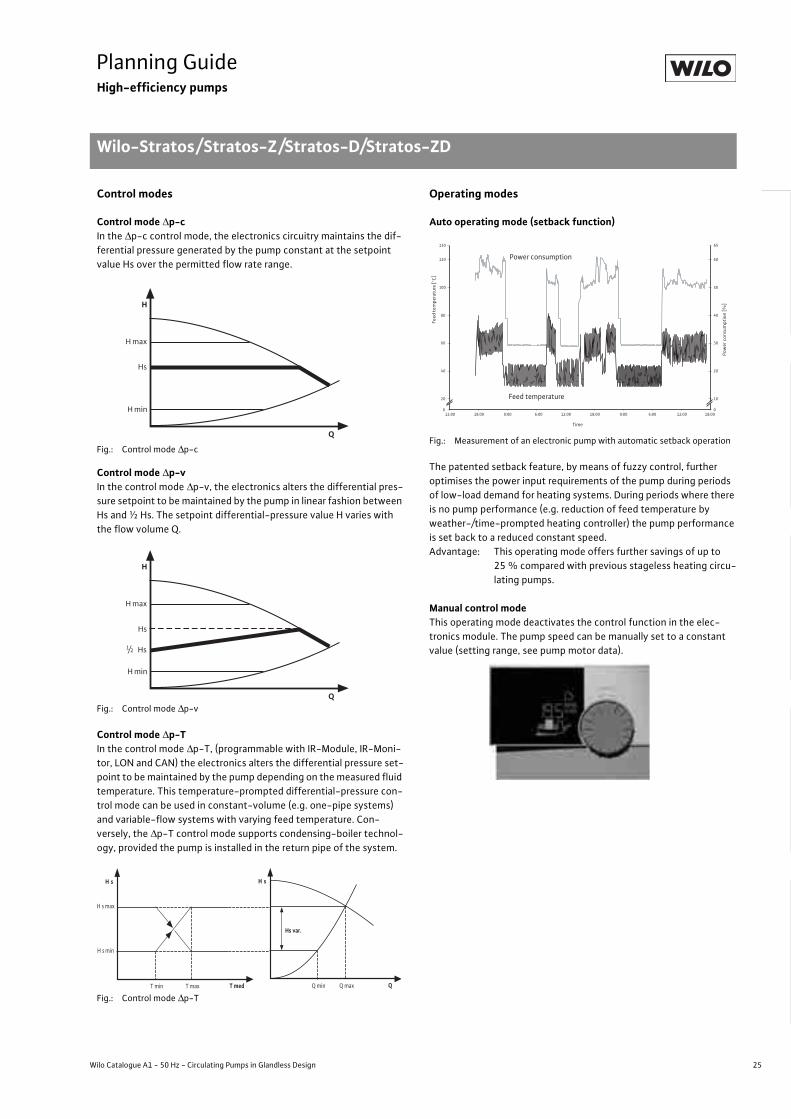
25
Planning GuideHigh-efficiency pumps
Wilo-Stratos/Stratos-Z/Stratos-D/Stratos-ZD
Wilo Catalogue A1 - 50 Hz - Circulating Pumps in Glandless Design
Hea
ting,
Air-
cond
ition
ing,
Co
olin
gSe
cond
ary
Hot W
ater
Circ
ulat
ion
Sola
r The
rmal
, Geo
ther
mal
En
ergy
Sys
tem
sSe
rvic
e/Ac
cess
orie
s, S
yste
ms
Switc
hgea
rs a
nd C
ontr
ol
Dev
ices
Pum
p M
anag
emen
t Sys
tem
s
Control modes
Control mode �p-cIn the �p-c control mode, the electronics circuitry maintains the dif-ferential pressure generated by the pump constant at the setpoint value Hs over the permitted flow rate range.
Fig.: Control mode �p-c
Control mode �p-vIn the control mode �p-v, the electronics alters the differential pres-sure setpoint to be maintained by the pump in linear fashion between Hs and ½ Hs. The setpoint differential-pressure value H varies with the flow volume Q.
Fig.: Control mode �p-v
Control mode �p-TIn the control mode �p-T, (programmable with IR-Module, IR-Moni-tor, LON and CAN) the electronics alters the differential pressure set-point to be maintained by the pump depending on the measured fluid temperature. This temperature-prompted differential-pressure con-trol mode can be used in constant-volume (e.g. one-pipe systems) and variable-flow systems with varying feed temperature. Con-versely, the �p-T control mode supports condensing-boiler technol-ogy, provided the pump is installed in the return pipe of the system.
Fig.: Control mode �p-T
Operating modes
Auto operating mode (setback function)
Fig.: Measurement of an electronic pump with automatic setback operation
The patented setback feature, by means of fuzzy control, further optimises the power input requirements of the pump during periods of low-load demand for heating systems. During periods where there is no pump performance (e.g. reduction of feed temperature by weather-/time-prompted heating controller) the pump performance is set back to a reduced constant speed.Advantage: This operating mode offers further savings of up to
25 % compared with previous stageless heating circu-lating pumps.
Manual control modeThis operating mode deactivates the control function in the elec-tronics module. The pump speed can be manually set to a constant value (setting range, see pump motor data).
H max
H
H min
Hs
Q
H max
H
H min
Hs
Q
Hs1/2
H s min
H s
Hs var.
QQ min Q max
H s
T medT min T max
H s max
Pow
er c
onsu
mpt
ion
[%]
0
20
40
60
80
100
120
130
12:00 18:00 0:00 6:00 12:00 18:00 0:00 6:00 12:00 18:00
Time
0
10
20
30
40
50
60
65
Power consumption
Feed temperature
Feed
tem
pera
ture
[°C
]
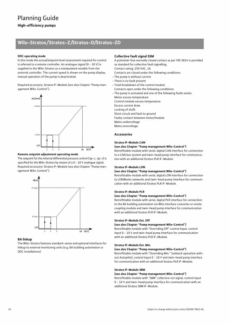
26 Subject to change without prior notice 09/2007 WILO AG
Planning GuideHigh-efficiency pumps
Wilo-Stratos/Stratos-Z/Stratos-D/Stratos-ZD
DDC operating modeIn this mode the actual/setpoint level assessment required for control is referred to a remote controller. An analogue signal (0 - 10 V) is supplied to the Wilo-Stratos as a manipulated variable from the external controller. The current speed is shown on the pump display, manual operation of the pump is deactivated.
Required accessory: Stratos IF-Module (see also Chapter “Pump man-agement Wilo-Control”).
Remote setpoint adjustment operating modeThe setpoint for the internal differential pressure control (�p-c, �p-v) is specified for the Wilo-Stratos by means of a 0 - 10 V analogue signal.Required accessory: Stratos IF-Module (see also Chapter “Pump man-agement Wilo-Control”).
BA linkupThe Wilo-Stratos features standard-series and optional interfaces for linkup to external monitoring units (e.g. BA building automation or DDC installations).
Collective fault signal SSMA potential-free normally closed contact as per VDI 3814 is provided as standard for collective fault signalling.Contact rating: 250 VAC, 1AContacts are closed under the following conditions:
- The pump is without current- There is no fault present- Total breakdown of the control module
Contacts open under the following conditions:- The pump is activated and one of the following faults exists:
Motor excess temperatureControl module excess temperature Excess current drawLocking of shaftShort circuit and fault to ground Faulty contact between motor/moduleMains undervoltageMains overvoltage
Accessories
Stratos IF-Module CAN(see also Chapter “Pump management Wilo-Control”)Retrofittable module with serial, digital CAN interface for connection to a CAN bus system and twin-head pump interface for communica-tion with an additional Stratos PLR IF-Module.
Stratos IF-Module LON(see also Chapter “Pump management Wilo-Control”)Retrofittable module with serial, digital LON interface for connection to LONWorks networks and twin-head pump interface for communi-cation with an additional Stratos PLR IF-Module.
Stratos IF-Module PLR(see also Chapter “Pump management Wilo-Control”)Retrofittable module with serial, digital PLR interface for connection to the BA building automation via Wilo interface converter or onsite coupling module and twin-head pump interface for communication with an additional Stratos PLR IF-Module.
Stratos IF-Module Ext. Off(see also Chapter “Pump management Wilo-Control”)Retrofittable module with “Overriding Off” control input, control input 0 - 10 V and twin-head pump interface for communication with an additional Stratos PLR IF-Module.
Stratos IF-Module Ext. Min.(see also Chapter “Pump management Wilo-Control”)Retrofittable module with “Overriding Min.” (setback operation with-out Autopilot), control input 0 - 10 V and twin-head pump interface for communication with an additional Stratos PLR IF-Module.
Stratos IF-Module SBM(see also Chapter “Pump management Wilo-Control”)Retrofittable module with “SBM” collective run signal, control input 0 - 10 V and twin-head pump interface for communication with an additional Stratos SBM IF-Module.
n[1/min]
n max
n min
Aus 10 U[V]1 3 2
Off
H max
H min
Aus
H[m]
10 U[V]1 3 2
Off
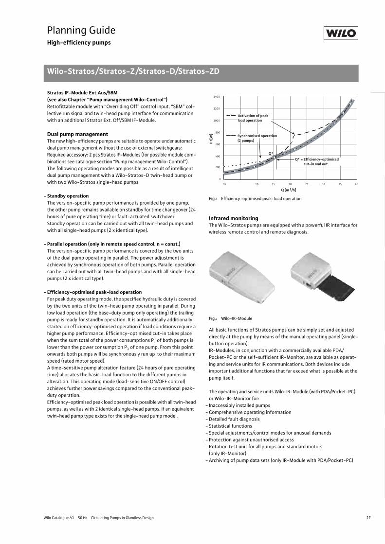
27
Planning GuideHigh-efficiency pumps
Wilo-Stratos/Stratos-Z/Stratos-D/Stratos-ZD
Wilo Catalogue A1 - 50 Hz - Circulating Pumps in Glandless Design
Hea
ting,
Air-
cond
ition
ing,
Co
olin
gSe
cond
ary
Hot W
ater
Circ
ulat
ion
Sola
r The
rmal
, Geo
ther
mal
En
ergy
Sys
tem
sSe
rvic
e/Ac
cess
orie
s, S
yste
ms
Switc
hgea
rs a
nd C
ontr
ol
Dev
ices
Pum
p M
anag
emen
t Sys
tem
s
Stratos IF-Module Ext.Aus/SBM(see also Chapter “Pump management Wilo-Control”)Retrofittable module with “Overriding Off” control input, “SBM” col-lective run signal and twin-head pump interface for communication with an additional Stratos Ext. Off/SBM IF-Module.
Dual pump managementThe new high-efficiency pumps are suitable to operate under automatic dual pump management without the use of external switchgears: Required accessory: 2 pcs Stratos IF-Modules (for possible module com-binations see catalogue section “Pump management Wilo-Control”).The following operating modes are possible as a result of intelligent dual pump management with a Wilo-Stratos-D twin-head pump or with two Wilo-Stratos single-head pumps:
- Standby operationThe version-specific pump performance is provided by one pump, the other pump remains available on standby for time changeover (24 hours of pure operating time) or fault-actuated switchover. Standby operation can be carried out with all twin-head pumps and with all single-head pumps (2 x identical type).
- Parallel operation (only in remote speed control, n = const.)The version-specific pump performance is covered by the two units of the dual pump operating in parallel. The power adjustment is achieved by synchronous operation of both pumps. Parallel operation can be carried out with all twin-head pumps and with all single-head pumps (2 x identical type).
- Efficiency-optimised peak-load operationFor peak duty operating mode, the specified hydraulic duty is covered by the two units of the twin-head pump operating in parallel. During low load operation (the base-duty pump only operating) the trailing pump is ready for standby operation. It is automatically additionally started on efficiency-optimised operation if load conditions require a higher pump performance. Efficiency-optimised cut-in takes place when the sum total of the power consumptions P1 of both pumps is lower than the power consumption P1 of one pump. From this point onwards both pumps will be synchronously run up to their maximum speed (rated motor speed).A time-sensitive pump alteration feature (24 hours of pure operating time) allocates the basic-load function to the different pumps in alteration. This operating mode (load-sensitive ON/OFF control) achieves further power savings compared to the conventional peak-duty operation. Efficiency-optimised peak load operation is possible with all twin-head pumps, as well as with 2 identical single-head pumps, if an equivalent twin-head pump type exists for the single-head pump model.
.
Fig.: Efficiency-optimised peak-load operation
Infrared monitoringThe Wilo-Stratos pumps are equipped with a powerful IR interface for wireless remote control and remote diagnosis.
Fig.: Wilo-IR-Module
All basic functions of Stratos pumps can be simply set and adjusted directly at the pump by means of the manual operating panel (single-button operation).IR-Modules, in conjunction with a commercially available PDA/Pocket-PC or the self-sufficient IR-Monitor, are available as operat-ing and service units for IR communications. Both devices include important additional functions that far exceed what is possible at the pump itself.
The operating and service units Wilo-IR-Module (with PDA/Pocket-PC) or Wilo-IR-Monitor for:
- Inaccessibly installed pumps- Comprehensive operating information- Detailed fault diagnosis- Statistical functions- Special adjustments/control modes for unusual demands- Protection against unauthorised access- Rotation test unit for all pumps and standard motors
(only IR-Monitor)- Archiving of pump data sets (only IR-Module with PDA/Pocket-PC)
0
200
400
600
800
1000
1200
1400
05 10 15 20 25 30 35 40
Q [m 3/h]
P1[
W]
Activation of peak-load operation
Q*
Synchronised operation (2 pumps)
Q* = Efficiency-optimised cut-in and out

28 Subject to change without prior notice 09/2007 WILO AG
Planning GuideHigh-efficiency pumps
Wilo-Stratos/Stratos-Z/Stratos-D/Stratos-ZD
As is the case with the Stratos pumps, the IR-Monitor is equipped with 1-button operation and an LC display. An operator program with a graphics user interface runs on the PDA/Pocket-PC.
Application in compact manifoldsIn narrow and low-clearance situations the control module can be put in a vertical position by turning the motor. Dimension b4 serves as the minimum clearance (x) for application of thermal insulation shells (see Chapter “Dimensions, weights”).
Fig.: Simplified illustration, installation dimensions of additional fittings must be allowed for.
Installation and electrical connectionInstallation of the Wilo-Stratos is uncomplicated, because the flanges are readily accessible due to the positioning of the control module and because the terminal room is also accessible from the front. The pump and module installation positions provide for highly variable installa-tions.All of the high-efficiency pumps of the Wilo-Stratos/Stratos-Z/Stratos-D/Stratos-ZD series can be hooked up to the following volt-ages and frequencies:1~230 V, 50/60 Hz, tolerance as per DIN IEC 60038 ± 10 %3~230 V, 50/60 Hz, tolerance as per DIN IEC 60038 ± 10 %
Permitted installation positions
Single-head pumps:
Twin-head pumps:
Operation on residual-current devices (RCD)The operation of the Wilo-Stratos at residual current-operated pro-tective devices in accordance with DIN EN 61008-1 is permissible without functional impairment of the residual current-operated pro-tective device (DIN VDE 0160). Suitable RCD circuit-breakers are identified by or .

29
Planning GuideHigh-efficiency pumps
Wilo-Stratos ECO/ECO-BMS/ECO-Z/ECO-Z-BMS/ECO-ST
Wilo Catalogue A1 - 50 Hz - Circulating Pumps in Glandless Design
Hea
ting,
Air-
cond
ition
ing,
Co
olin
gSe
cond
ary
Hot W
ater
Circ
ulat
ion
Sola
r The
rmal
, Geo
ther
mal
En
ergy
Sys
tem
sSe
rvic
e/Ac
cess
orie
s, S
yste
ms
Switc
hgea
rs a
nd C
ontr
ol
Dev
ices
Pum
p M
anag
emen
t Sys
tem
s
Wilo-Stratos ECO, Stratos ECO-BMS, Stratos ECO-Z, Stratos ECO-Z-BMS, Stratos ECO-STThe Wilo-Stratos ECO series with the variants Stratos ECO-BMS, ECO-Z, ECO-Z-BMS and ECO-ST are extensions of the previously described Wilo-Stratos series that have the following advantages:
- Energy savings of up to 80 % compared with standard pumps- Stratos ECO and ECO-BMS version for all heating systems in the tem-
perature range +15 °C to +110 °C- Stratos ECO-ST version for solar thermal systems in the temperature
range +15 °C to +110 °C- Automatic adjustment of pump performance to continually changing
hydraulic system load conditions- Preventing flow noise- Reliability and comfort during installation and operation
Fields of applicationThe Wilo-Stratos ECO, ECO-BMS and ECO-ST series are suitable for utilisation as high-efficiency pumps in circulation systems for heat-ing and in solar-powered systems in 1-6-family houses.
Temperature rangeFluid temperature range from +15 °C to +110 °C at ambient temper-atures of 0 °C up to a maximum of +40 °C.
Heating applicationBecause of its corrosion-resistant pump housing made of red brass, the Wilo-Stratos ECO in the RG version is particularly suitable for installations subject to possible oxygen entry, e.g. floor heating sys-tems with heating surfaces made of plastic tubing.
Thermal insulation with heating applicationsThe pumps of the Wilo-Stratos ECO series (except Stratos ECO-ST) are equipped as standard with thermal insulation shells in order to prevent thermal losses through the pump housing. The EPP material used (foamed polypropylene), has the following properties:
- Environmental compatibility: easily recyclable- Thermal resistance: up to 120 °C- Transmission coefficient: 0.04 W/mK as per DIN 52612- Flammability: class B2 as per DIN 4102 (normal flammability)
Normally flammable materials are permitted to be utilised in heating areas in Germany in accordance with fire prevention regulations as long as a minimum clearance of 20 cm is maintained between them and the fireplace.
Application of secondary hot water circulation(Wilo-Stratos ECO-Z, ECO-Z-BMS)Pumps which are utilised in secondary hot water circulation system are subject to specific requirements that are fulfilled by the Wilo-Stratos ECO-Z and ECO-Z-BMS series:
- Fluids are secondary hot water and water for food businesses as per TrinkwV 2001. The formation of calcium deposits has been taken into account in the structural design, so that a total carbonate hardness of 20°d is authorised for a maximum fluids temperature of +65 °C.
- All plastic parts that come into contact with the pumped liquid are in conformance with KTW recommendations.
Automatic air ventilationRotor space ventilation is effected automatically by the filter and flow channel system. As the pumping medium flows into the rotor space, a filter plug in the shaft and a filter disc in the bearing plate prevent the ingress of the smallest abrasive particles.The seal between impeller and bearing plate prevents dirt from accu-mulating in the A-bearing gap on the motor side.Advantage: The automatic ventilation of the rotor space is accel-
erated, thus reducing both dry-running times and ventilation noise.
Advantage: Damage to the radial bearings or to the can is avoided by the filtering-out feature.
Motor protectionThe standard series integrated protection device reliably protects the pump, in all settings, against excess temperature, excess current draw and rotor locking.Advantage: No external motor protection switch is required.
The connecting instructions of the local electricity supply companies are to be observed.If, for example at the time of replacement, a motor protection switch is present in the electrical installa-tion that cannot be bridged, then it is to be set to the maximum current specified on the name plate.
Manual operation
Control buttonAll versions of the Wilo-Stratos ECO series are operated using the proven red-button technology (1-button operation). The important basic functions can thus be safely and comfortably set and adjusted.
Control mode �p-vIn the control mode p-v, the differential pressure setpoint is raised above the permitted volume flow range in linear fashion between ½ Hs and Hs. The differential pressure generated by the pump is regulated to the respective differential pressure setpoint.
Fig.: Control mode �p-v
H max
H
H min
Hs
Q
Hs1/2

30 Subject to change without prior notice 09/2007 WILO AG
Planning GuideHigh-efficiency pumps
Wilo-Stratos ECO/ECO-BMS/ECO-Z/ECO-Z-BMS/ECO-ST
Auto operating mode (setback function)
Fig.: Measurement of an electronic pump with automatic setback operation
The patented setback feature, by means of fuzzy control, further optimises the power input requirements of the pump during periods of low-load demand for heating systems. During periods where there is no pump performance (e.g. reduction of feed temperature by weather-/time-prompted heating controller) the pump performance is set back to a reduced constant speed.Advantage: This operating mode offers further savings of up to
25 % compared with previous stageless heating circu-lating pumps.
Building automation (BA) connection(with Stratos ECO-BMS, ECO-Z-BMS and ECO-ST)The Wilo-Stratos versions ECO-BMS, ECO-Z-BMS and ECO-ST fea-ture as standard equipment a collective fault signal, the function External OFF and the 0 - 10 V control input for linkup to external monitoring units (e.g. BA building automation or DDC installations).
Collective fault signal SSMA potential-free normally closed contact as per VDI 3814 is provided as standard for collective fault signalling.Contact rating: 250 VAC, 1AContacts are closed under the following conditions:
- The pump is without current- There is no fault present- Total breakdown of the control module
Contacts open under the following conditions:- The pump is activated and one of the following faults exists:
- motor overheating- excess temperature control module- excess current draw- blocking of the shaft- short circuit and fault to ground- faulty contact between motor/module- mains undervoltage- mains overvoltage
Control input 0 - 10 VIn this mode the actual/setpoint level assessment required for control is referred to a remote controller. The Wilo-Stratos ECO-BMS/ECO-Z-BMS and ECO-ST are supplied with an analogue signal (0 - 10 V) from the external controller as manipulated variable. As an alternative, a fixed speed can be set locally at the red button.
Control input External OFFInput for potential-free NC contact. The pump operates under auto control when the contact is closed.An open contact stops the pump.
Pow
er c
onsu
mpt
ion
[%]
0
20
40
60
80
100
120
130
12:00 18:00 0:00 6:00 12:00 18:00 0:00 6:00 12:00 18:00
Time
0
10
20
30
40
50
60
65
Power consumption
Feed temperature
Feed
tem
pera
ture
[°C
]
n[1/min]
n max
n min
Aus 10 U[V]1 3 2
Off

31
Planning GuideEnergy-saving pumps
Wilo-Star-E, Wilo-TOP-E, TOP-ED
Wilo Catalogue A1 - 50 Hz - Circulating Pumps in Glandless Design
Hea
ting,
Air-
cond
ition
ing,
Co
olin
gSe
cond
ary
Hot W
ater
Circ
ulat
ion
Sola
r The
rmal
, Geo
ther
mal
En
ergy
Sys
tem
sSe
rvic
e/Ac
cess
orie
s, S
yste
ms
Switc
hgea
rs a
nd C
ontr
ol
Dev
ices
Pum
p M
anag
emen
t Sys
tem
s
Wilo-Star-E (EasyStar) seriesThe energy-saving pumps of the Wilo-Star-E series provide the entire performance range for one-family to six-family houses. They can be utilised with all conventional pipe systems (single-pipe and twin-pipe heating systems) and offer the possibility of adjusting the delivery head-setpoints between 0.5 m and 5 m.
Control technology Wilo-Star-E
Control mode �p-variable (�p-v):In the control mode �p-v, the electronics alters the differential pres-sure to be maintained by the pump in linear fashion between Hs and 1/2 Hs. The differential pressure setpoint H alters with the flow volume Q.
“Autopilot” automatic setback operationWith the standard series integrated Autopilot Wilo is the first pump manufacturer worldwide to offer a fully automatic self-teaching set-back operation for small electronically controlled pumps with screwed connections.The patented setback process by fuzzy control enables further opti-misation on the power input demand of the pump under low-load conditions of the heating system. When the heating water reaches a specific lower temperature (e.g. reduction of feed temperature by weather-/time-prompted heating controller), the pump is run down to a reduced constant speed.This operating mode features further savings of up to 25 % in com-parison with previous steplessly adjustable pumps.
Fig.: Measurement of an electronic pump with automatic setback operation
StandardsThe Wilo energy-saving pumps are distinguished by proven stand-ards such as the “red-button technology” for practice-oriented delivery head presetting.
Wilo-TOP-E/-ED seriesThe world’s first electronically controlled circulating pump with standard integrated display screen and manual control panel (single button operation). It comes as standard with the unique, patented “Autopilot” automatic setback control facility based on the latest cutting-edge Fuzzy technology.Without the need for external switchgears, automatic stageless dif-ferential-pressure control offers:
- Energy savings of up to 50 % and thus reduced operating costs and reduced CO2 emissions
- Elimination of noises from thermostatic valves.The Wilo-TOP-E series is available across the entire performance range from Rp 1 to DN 100 and is suitable for fluid temperatures up to Tmax = 110 °C.
Manual operationThe basic functions of the Wilo-TOP-E/-ED pumps can be parame-terised at the manual operation level:
- ON/OFF control- Control mode (�p-c, �p-v, manual control mode)- Differential pressure setpoint- Automatic setback to minimum speed- Twin-head pump function (main/standby or parallel operation)
All operating states as well as a wide range of fault and alarm signals (fault signals result in immediate shutdown) are indicated directly in the standard series pump display.
Fig.: Manual operation level (pump display and operating button)
Fig.: Symbols featured in pump display
Q
Hs
/ Hs 1 2
�p-v
Regelungsart H control mode
Pow
er c
onsu
mpt
ion
[%]
0
20
40
60
80
100
120
130
12:00 18:00 0:00 6:00 12:00 18:00 0:00 6:00 12:00 18:00
Time
0
10
20
30
40
50
60
65
Power consumption
Feed temperature
Feed
tem
pera
ture
[°C
]
H m
auto
on
Automatic setback operation
GLT communication HRPM
m x100
auto + /
on off
Keyboard lock
Control mode Dp-c
Control mode Dp-v
Control mode (n-const.)
Control mode Dp-T Analog input 0-10 V
Pump On
Pump Off
Parallel operation
Standby operation
Unit, delivery head
Unit, motor speed
Pump at min. speed
Pump under auto control Current set point level
10V
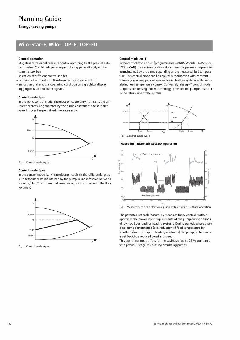
32 Subject to change without prior notice 09/2007 WILO AG
Planning GuideEnergy-saving pumps
Wilo-Star-E, Wilo-TOP-E, TOP-ED
Control operationStageless differential pressure control according to the pre-set set-point value. Combined operating and display panel directly on the terminal box for:
- selection of different control modes- setpoint adjustment in m (the lower setpoint value is 1 m)- indication of the actual operating condition on a graphical display- logging of fault and alarm signals.
Control mode �p-cIn the �p-c control mode, the electronics circuitry maintains the dif-ferential pressure generated by the pump constant at the setpoint value Hs over the permitted flow rate range.
Fig.: Control mode �p-c
Control mode �p-vIn the control mode �p-v, the electronics alters the differential pres-sure setpoint to be maintained by the pump in linear fashion between Hs and 1/2 Hs. The differential pressure setpoint H alters with the flow volume Q.
Fig.: Control mode �p-v
Control mode �p-TIn the control mode �p-T, (programmable with IR-Module, IR-Monitor, LON or CAN) the electronics alters the differential pressure setpoint to be maintained by the pump depending on the measured fluid tempera-ture. This control mode can be applied in conjunction with constant-volume (e.g. one-pipe) systems and variable-flow systems with mod-ulating feed temperature control. Conversely, the �p-T control mode supports condensing-boiler technology, provided the pump is installed in the return pipe of the system.
Fig.: Control mode �p-T
“Autopilot” automatic setback operation
Fig.: Measurement of an electronic pump with automatic setback operation
The patented setback feature, by means of fuzzy control, further optimises the power input requirements of the pump during periods of low-load demand for heating systems. During periods where there is no pump performance (e.g. reduction of feed temperature by weather-/time-prompted heating controller) the pump performance is set back to a reduced constant speed.This operating mode offers further savings of up to 25 % compared with previous stageless heating circulating pumps.
Q
H max
Hs
H min
H
Q
H max
Hs
H min
½Hs
H
Hs max
Q
Hs min
T min T max Q min Q max
Hs var .
Hs Hs
TMed
Pow
er c
onsu
mpt
ion
[%]
0
20
40
60
80
100
120
130
12:00 18:00 0:00 6:00 12:00 18:00 0:00 6:00 12:00 18:00
Time
0
10
20
30
40
50
60
65
Power consumption
Feed temperature
Feed
tem
pera
ture
[°C
]

33
Planning GuideEnergy-saving pumps
Wilo-Star-E, Wilo-TOP-E, TOP-ED
Wilo Catalogue A1 - 50 Hz - Circulating Pumps in Glandless Design
Hea
ting,
Air-
cond
ition
ing,
Co
olin
gSe
cond
ary
Hot W
ater
Circ
ulat
ion
Sola
r The
rmal
, Geo
ther
mal
En
ergy
Sys
tem
sSe
rvic
e/Ac
cess
orie
s, S
yste
ms
Switc
hgea
rs a
nd C
ontr
ol
Dev
ices
Pum
p M
anag
emen
t Sys
tem
s
Manual control mode
The manual control mode deactivates the control in the electronics module. The speed of the pump can be set manually to a constant value between 800 and 2.800 1/min.
BA linkupThe Wilo-TOP-E/-ED pumps feature standard-series and optional interfaces for linkup to external monitoring units (e.g. DDC/BA).
Collective fault signal SSMAll pumps of the Wilo-TOP-E/-ED series are equipped with a poten-tial-free contact (normally closed contact in accordance with VDI 3814) for collective fault signalling. Contact load
- minimum permissible: 12 V DC, 10 mA,- maximum permissible: 250 V AC, 1 A.
Any fault, due to any one of the following causes, will be signalled by the collective fault signal:
- motor excess temperature- module excess temperature- excess current draw- blocking- short circuit and fault to ground
Neither a mains failure nor a total failure of the electronics is inter-preted as a fault. The pump resumes running automatically after the resumption of electricity from the mains.
Control input Overriding OffThe Wilo-TOP-E/-ED pumps, beginning with a rated motor power of P2 = 350 W, are equipped with an Ext. Off. control input for the pur-pose of switchoff by external control units. The control input received here overrides all other control commands (contacts open: pump off).Wilo-TOP-E/-ED pumps with lower rated outputs can be switched off directly via the mains power cable.
Analogue input 0 - 10 V
The speed can be adjusted in the Manual control mode, depending on an external control voltage (0 - 10 V), with Wilo-TOP-E/-ED pumps and a rated motor power of P2 = 350 W or higher. The electronics module control is deactivated in such case.
“IF-Module” serial interfaceThe Wilo-IF-Module has the option of being retrofitted in the termi-nal boxes of Wilo-TOP-E/-ED pumps. Extensive Wilo-TOP-E/-ED pumps operating data is available with the Wilo-IF-Module. This data can be transferred with the Wilo-specific, serial, digital PLR interface of the PLR IF-Module by means of a two-wire connection via inter-face converter or company-specific coupling module to modern building automation systems (BA).With the LON IF-Module, this data can also be transferred by means of two-wire connection via a manufacturer-neutral, open LONWorks network to modern BA systems.
Dual pump managementThe electronic pumps are suitable for operation under automatic dual pump management without the use of external control devices.Required accessory: 2 pieces IF-Module.The following operating modes are possible as a result of intelligent dual pump management with one Wilo-TOP-ED- or two Wilo-TOP-E pumps.
- Stand-by operationThe configuration pump performance is achieved by the respective main pump in individual operation. The other pump stands in reserve, ready for time-actuated (24-hour) and/or fault-actuated switchover. Standby operation can be carried out with all twin-head pumps and with all single-head pumps (2 x identical type).
- Parallel operation (only in remote speed control, n =const.)The version-specific pump performance is covered by the two units of the dual pump operating in parallel. The power adjustment is achieved by synchronous operation of both pumps. Parallel operation can be carried out with all twin-head pumps and with all single-head pumps (2 x identical type).
- Efficiency-optimised peak-load operationFor peak duty operating mode, the specified hydraulic duty is covered by the two units of the twin-head pump operating in parallel.During low load operation (the base-duty pump only operating) the trailing pump is ready for standby operation. It is automatically addi-tionally started on efficiency-optimised operation if load conditions require a higher pump performance. Efficiency-optimised cut-in takes place when the sum total of the power consumptions P1 of both pumps is lower than the power consumption P1 of one pump.
RPM x100
on
RPM x100
on10V
n[1/min]
n max
n min
Aus 10 U[V]1 3 2
Off

34 Subject to change without prior notice 09/2007 WILO AG
Planning GuideEnergy-saving pumps
From this point onwards both pumps will be synchronously run up to their maximum speed (rated motor speed).Time-sensitive pump duty cycling (24 h operating period) alternately allocates the basic-load function to the pumps. This operating mode (load-sensitive ON/OFF control) achieves further power savings compared to the conventional peak-duty operation.Efficiency-optimised peak load operation is possible with all twin-head pumps, as well as with 2 identical single-head pumps, if an equivalent twin-head pump type exists for the single-head pump model.
Fig.: Efficiency-optimised peak-load operation (here: Wilo-TOP-ED 50/1-7; �p-c; Hs = 2 m)
Infrared monitoringTOP-E/-ED pumps are equipped with a powerful IR interface for wireless remote control and remote diagnosis. All basic functions of TOP-E/-ED pumps can be simply set and adjusted directly at the pump by means of the manual operating panel (single-button operation).IR-Modules, in conjunction with a commercially available PDA/Pocket-PC or the self-sufficient IR-Monitor, are available as operating and serv-ice units for IR communications. Both devices include important addi-tional functions that far exceed what is possible at the pump itself.
The operating and service units Wilo-IR-Module (with PDA/Pocket-PC) or Wilo-IR-Monitor for:
- Inaccessibly installed pumps- Comprehensive operating information- Detailed fault diagnosis- Statistical functions- Special adjustments/control modes for unusual demands- Protection against unauthorised access- Rotation test unit for all pumps and standard motors
(only IR-Monitor)- Archiving of pump data sets (only IR-Module with PDA/Pocket-PC)
As is the case with the TOP-E/-ED pumps, the IR-Monitor is equipped with a 1-button operation and an LC display. The main operating func-tion of the IR-Monitor corresponds to those at the pump itself. An oper-ator program with a graphics user interface runs on the PDA/Pocket-PC.
Operation on residual-current devices (RCD)The operation of the Wilo-TOP-E/-ED series at residual current-operated protective devices in accordance with DIN EN 61008-1 is permissible without functional impairment of the residual current-operated protective device (DIN VDE 0160). Suitable RCD circuit-breakers are identified by or .
0
200
400
600
800
1000
1200
1400
0 5 10 15 20 25 30 35 40
Q [m 3/h]
P1[
W]
Activation of peak-load operation
Q*
Synchronised operation (2 pumps)
Q* = Efficiency-optimised cut-in and out

35
Heating, Air-conditioning, CoolingContents
Wilo Catalogue A1 - 50 Hz - Circulating Pumps in Glandless Design
Hea
ting,
Air-
cond
ition
ing,
Co
olin
gSe
cond
ary
Hot W
ater
Circ
ulat
ion
Sola
r The
rmal
, Geo
ther
mal
En
ergy
Sys
tem
sSe
rvic
e/Ac
cess
orie
s, S
yste
ms
Switc
hgea
rs a
nd C
ontr
ol
Dev
ices
Pum
p M
anag
emen
t Sys
tem
s
Heating, air-conditioning, cooling
High-efficiency pumps Wilo-Stratos ECO, Stratos, Stratos-D 40
Series overview 40
Wilo-Stratos-ECO 40
Equipment/function 42
Series description 44
Technical data 46
Pump curves 48
Terminal diagrams, motor data 49
Dimensions, weights 50
Wilo-Stratos 40
Equipment/function 42
Series description 52
Technical data 54
Pump curves 58
Terminal diagrams, motor data 65
Dimensions, weights 66
Wilo-Stratos-D 40
Equipment/function 68
Series description 70
Technical data 72
Pump curves 74
Terminal diagrams, motor data 79
Dimensions, weights 80
Energy-saving pumps Wilo-Star-E (EasyStar), TOP-E, TOP-ED 82
Series overview 82
Wilo-Star-E (EasyStar) 82
Equipment/function 84
Series description 86
Technical data 88
Pump curves 90
Terminal diagrams, motor data 91
Dimensions, weights 92
Wilo-TOP-E 82
Equipment/function 84
Series description 94
Technical data 96
Pump curves 98
Terminal diagrams, motor data 103
Dimensions, weights 104

36 Subject to change without prior notice 09/2007 WILO AG
Heating, Air-conditioning, CoolingContents
Energy-saving pumps (continued) Wilo-TOP-ED 82
Equipment/function 106
Series description 109
Technical data 111
Pump curves 113
Terminal diagrams, motor data 117
Dimensions, weights 118
Automatic pumps Wilo-Smart 122
Series overview 122
Wilo-Smart 122
Equipment/function 124
Series description 126
Technical data 128
Pump curves 130
Terminal diagrams, motor data, dimensions, weights 131
Standard pumps Wilo-Star-RS (ClassicStar), Wilo-AXL, Wilo-TOP-RL 132
Series overview 132
Wilo-SE, Wilo-TOP-S, Wilo-TOP-D 134
Series overview 134
Wilo-RP, Wilo-P 136
Series overview 136
Wilo-Star-RSD (ClassicStar), Wilo-TOP-SD, Wilo-SE-TW 138
Series overview 138
Wilo-DOP 140
Series overview 140
Wilo-Star-RS (ClassicStar) 132
Equipment/function 142
Series description 148
Technical data 150
Pump curves 154
Terminal diagrams, motor data 156
Dimensions, weights 157
Heating, air-conditioning, cooling

37
Heating, Air-conditioning, CoolingContents
Wilo Catalogue A1 - 50 Hz - Circulating Pumps in Glandless Design
Hea
ting,
Air-
cond
ition
ing,
Co
olin
gSe
cond
ary
Hot W
ater
Circ
ulat
ion
Sola
r The
rmal
, Geo
ther
mal
En
ergy
Sys
tem
sSe
rvic
e/Ac
cess
orie
s, S
yste
ms
Switc
hgea
rs a
nd C
ontr
ol
Dev
ices
Pum
p M
anag
emen
t Sys
tem
s
Standard pumps (continued) Wilo-AXL 132
Equipment/function 142
Series description 159
Technical data 160
Pump curves, terminal diagrams, motor data 162
Dimensions, weights 163
Wilo-TOP-RL 132
Equipment/function 142
Series description 164
Technical data 166
Pump curves 168
Terminal diagram, motor data 170
Dimensions, weights 171
Wilo-SE 134
Equipment/function 142
Series description 172
Technical data 174
Pump curves 176
Terminal diagram, motor data 177
Dimensions, weights 178
Wilo-TOP-S 134
Equipment/function 145
Series description 180
Technical data 182
Pump curves 188
Terminal diagrams 197
Motor data 198
Dimensions, weights 201
Wilo-TOP-D 134
Equipment/function 145
Series description 204
Technical data 206
Pump curves 208
Terminal diagrams 210
Motor data 211
Dimensions, weights 212
Wilo-RP 136
Equipment/function 145
Series description 214
Technical data 216
Pump curves 218
Terminal diagrams 219
Motor data 220
Dimensions, weights 221
Heating, air-conditioning, cooling

38 Subject to change without prior notice 09/2007 WILO AG
Heating, Air-conditioning, CoolingContents
Standard pumps (continued) Wilo-P 136
Equipment/function 145
Series description 222
Technical data 224
Pump curves 226
Terminal diagrams 230
Motor data 230
Dimensions, weights 232
Wilo-Star-RSD (ClassicStar) 138
Equipment/function 234
Series description 238
Technical data 240
Pump curves 242
Terminal diagrams, motor data, dimensions, weights 243
Wilo-TOP-SD 138
Equipment/function 234
Series description 244
Technical data 246
Pump curves 250
Terminal diagrams, motor data 263
Dimensions, weights 266
Wilo-SE-TW 138
Equipment/function 234
Series description 268
Technical data 270
Pump curves 272
Terminal diagrams, motor data 274
Dimensions, weights 275
Wilo-DOP 140
Equipment/function 234
Series description 276
Technical data 278
Pump curves 280
Terminal diagrams 285
Motor data 286
Dimensions, weights 287
Heating, air-conditioning, cooling

Fast pump exchange at+49 1511 4 44 44 66.Wilo text message replacement guide.
Exchange recommendation via mobile phone.All types of pumps available.
Always reachable.Quick help.
With the Wilo text message replacement guide, you will now get individualrecommendations sent to your mobile phone – and that 24 hours a day, 7 days a week. After a simple text message query with the pump designation(e.g., S 50/100), Wilo will send you the ideal exchange product solution within a maximum of 20 seconds with all installation and fitting information,including the order numbers. Advanced? We call this Pumpen Intelligenz.
www.wilo.com

40 Subject to change without prior notice 09/2007 WILO AG
Heating, Air-conditioning, CoolingHigh-efficiency pumps (single-head pumps/twin-head pumps)
Series overview Wilo-Stratos ECO, Stratos, Stratos-D
Series: Wilo-Stratos ECO
> Single-head pumps:• Electronically controlled circulating pumps
with screwed connection> Application:• High efficiency pump especially for single-
and two-family houses, as well as for two to six-family houses. For hot water heating systems of all kinds.
> Special features:• Obtainable with pump housing in red brass
as version …RG• Can be connected to building automation
devices as model …BMS (with Building Man-agement System)
• Obtainable as a ventilation pump as model
Series: Wilo-Stratos
> Single-head pumps:• Electronically controlled circulating pumps
with screwed or flanged connection> Application: • Hot-water heating systems for all systems,
air-conditioning systems, closed cooling circuits, industrial circulating systems
Series: Wilo-Stratos-D
> Twin-head pumps:• Electronically controlled circulating pumps
with flanged connection> Application:• Hot-water heating systems for all systems,
air-conditioning systems, closed cooling circuits, industrial circulating systems
0
1
2
3
4
0 0,5 1,0 1,5 2,0 Q [m³/h]
H [m
]
Wilo-Stratos ECO
BMS
25(30)1-5
25(30)1-3

41
Heating, Air-conditioning, CoolingHigh-efficiency pumps (single-head pumps/twin-head pumps)
Series overview Wilo-Stratos ECO, Stratos, Stratos-D
Wilo Catalogue A1 - 50 Hz - Circulating Pumps in Glandless Design
Hea
ting,
Air-
cond
ition
ing,
Co
olin
gSe
cond
ary
Hot W
ater
Circ
ulat
ion
Sola
r The
rmal
, Geo
ther
mal
En
ergy
Sys
tem
sSe
rvic
e/Ac
cess
orie
s, S
yste
ms
Switc
hgea
rs a
nd C
ontr
ol
Dev
ices
Pum
p M
anag
emen
t Sys
tem
s
Series: Wilo-Stratos-ECO
> Product advantages:• Energy efficiency class A• Up to 80% energy savings in comparison to uncontrolled circulating pumps• High efficiency pump especially for single- and two-family houses, as well as for two to six-
family houses.• Highest degrees of efficiency due to ECM technology• Very high starting torque for secure starting (starting torque 3 x higher than conventional cir-
culating pumps)• Quick connection with spring clips• Optimal handling through front operation, variable installation positions• No noise due to Autopilot• Only 5.8 W minimum power consumption• Standard series thermal insulation for heating applications
>Additional information: Page:• Planning guide:. . . . . . . . . . . . . . . . . . . 6/29• Equipment/function . . . . . . . . . . . . . . 42• Series description: . . . . . . . . . . . . . . . . 44• Technical data: . . . . . . . . . . . . . . . . . . . 46• Pump curves: . . . . . . . . . . . . . . . . . . . . 48• Terminal diagrams, motor data: . . . . 49• Dimensions, weights: . . . . . . . . . . . . . 50• Service/accessories: . . . . . . . . . . . . . . 393• Switching and control devices:. . . . . 417• Pump management Wilo-Control:. . 489
Series: Wilo-Stratos
> Product advantages:• Energy efficiency class A• Highest degrees of efficiency due to ECM technology• Up to 80% energy savings in comparison to uncontrolled circulating pumps• Optimum handling through front-side operation and front-side access to the terminal room,
variable installation positions, position-independent display, combination flange PN 6/PN 10 (for DN 32 to DN 65)
• Standard series thermal insulation for heating applications• Utilisation in cooling/air-conditioning systems possible without ambient temperature restric-
tions• System expansion through retrofittable communication modules LON, CAN, PLR, etc.• Remote control via infrared interface (IR-Module/ IR-Monitor)
>Additional information: Page:• Planning guide:. . . . . . . . . . . . . . . . . . . 6/22• Equipment/function:. . . . . . . . . . . . . . 42• Series description: . . . . . . . . . . . . . . . . 52• Technical data: . . . . . . . . . . . . . . . . . . . 56• Pump curves: . . . . . . . . . . . . . . . . . . . . 58• Terminal diagrams, motor data: . . . . 65• Dimensions, weights: . . . . . . . . . . . . . 66• Service/accessories: . . . . . . . . . . . . . . 393• Switching and control devices:. . . . . 417• Pump management Wilo-Control:. . 489
Series: Wilo-Stratos-D
> Product advantages:• Energy efficiency class A• Highest degrees of efficiency due to ECM technology• Up to 80% energy savings in comparison to uncontrolled circulating pumps• Optimum handling through front-side operation and front-side access to the terminal room,
variable installation positions, position-independent display, combination flange PN 6/PN 10 (for DN 32 to DN 65)
• Utilisation in cooling/air-conditioning systems possible without ambient temperature restrictions• System expansion through retrofittable communication modules LON, CAN, PLR, etc.• Remote control via infrared interface (IR-Module/ IR-Monitor)• Integrable dual pump management through retrofittable Stratos IF-Modules for:
- Main/standby operation with fault-dependent switchover- Efficiency-optimised peak-load operation
>Additional information: Page:• Planning guide:. . . . . . . . . . . . . . . . . . . 6/22• Equipment/function:. . . . . . . . . . . . . . 68• Series description: . . . . . . . . . . . . . . . . 70• Technical data: . . . . . . . . . . . . . . . . . . . 72• Pump curves: . . . . . . . . . . . . . . . . . . . . 74• Terminal diagrams, motor data: . . . . 79• Dimensions, weights: . . . . . . . . . . . . . 80• Service/accessories: . . . . . . . . . . . . . . 393• Switching and control devices:. . . . . 417• Pump management Wilo-Control:. . 489

42 Subject to change without prior notice 09/2007 WILO AG
Heating, Air-conditioning, CoolingHigh-efficiency pumps (single-head pumps)
Equipment/function Wilo-Stratos ECO, Wilo-Stratos
Wilo-Stratos ECO Wilo-Stratos
Operating modes
Speed-stage switching – –
Manual control mode (n=constant) •(only Stratos ECO...-BMS) •
�p-c for constant differential pressure •(only Stratos ECO...-BMS) •
�p-v for variable differential pressure • •
�p-T for temperature-prompted differential pressure– •
(programmable via IR-Module, IR-Monitor, LON or CAN)
Manual functions
Setting the operating mode •(only Stratos ECO...-BMS)
•
Setting the differential-pressure setpoint • •Setting to “Autopilot” (automatic setback operation) • •
Setting the pump to ON/OFF •(only Stratos ECO...-BMS)
•
Setting the speed (manual setting mode) •(only Stratos ECO...-BMS)
•
Setting the speed stages – –
Automatic functions
Stageless power adjustment depending on the oper-ating mode • •
“Autopilot” automatic setback operation • •Deblocking function • •Soft start • •Safety control • –
Full motor protection with integrated trip electronics – •
External control functions
Control input “Overriding Off” •(only Stratos ECO...-BMS)
•Possible with Stratos IF-Modules (accessory)
Control input “Overriding Min” – •Possible with Stratos IF-Modules (accessory)
Control input “Analogue In 0 - 10 V” (remote speed adjustment)
•(only Stratos ECO...-BMS)
•Possible with Stratos IF-Modules (accessory)
Control input “Analogue In 0 - 10 V” (remote setpoint adjustment)
•(only Stratos ECO...-BMS)
•Possible with Stratos IF-Modules (accessory)
Signal and display functions
Single/collective fault signal (potential-free NC contact) – –
Collective fault signal (potential-free NC contact) •(only Stratos ECO...-BMS)
•
Individual run signal (potential-free NO contact) – •Possible with Stratos IF-Modules (accessory)
Thermal winding contact (WSK, potential-free NC contact) – –
• = available, – = not available

43
Heating, Air-conditioning, CoolingHigh-efficiency pumps (single-head pumps)
Equipment/function Wilo-Stratos ECO, Wilo-Stratos
Wilo Catalogue A1 - 50 Hz - Circulating Pumps in Glandless Design
Hea
ting,
Air-
cond
ition
ing,
Co
olin
gSe
cond
ary
Hot W
ater
Circ
ulat
ion
Sola
r The
rmal
, Geo
ther
mal
En
ergy
Sys
tem
sSe
rvic
e/Ac
cess
orie
s, S
yste
ms
Switc
hgea
rs a
nd C
ontr
ol
Dev
ices
Pum
p M
anag
emen
t Sys
tem
s
Signal and display functions (continued)
Fault signal light •(only Stratos ECO...-BMS) •
Direction-of-rotation control lamp – –
LC display for showing pump data and fault codes – •
Data exchange
Infrared interface for wireless data exchange with IR-Module/IR-Monitor (see IR-Module/IR-Monitor Function table)
– •
Serial digital PLR interface for connection to BA building automation via Wilo interface converter or company-specific coupling module
– •Possible with Stratos IF-Modules (accessory)
Serial digital LON interface for connection toa LONWorks network
– •Possible with Stratos IF-Modules (accessory)
Serial digital CAN interface for connection to a CAN bus system – •
Dual pump management (twin-head pump or 2 x single-head pump)
Main/standby operation (automatic fault-actuated switchover/time-sensitive pump alteration)
– •Various combinations with Stratos
IF-Modules (accessory) possible
Parallel operation (efficiency-optimised peak-load cut-in and out)
– •Various combinations with Stratos
IF-Modules (accessory) possible
Equipment/scope of delivery
Wrench attachment point on pump body • •(threaded pipe union pumps with P2 < 100 W)
Double switchover valve in pump housing – –
Cable entry possible on both sides • –
Wilo quick connection with spring clips • –
Integrated air extraction fitting for automatic rapid ventilator Rp 3/8
•(only Stratos ECO-L) –
Slot for optional extensions with Wilo-IF-Modules – •Blocking current-proof motor • –
Including seals for threaded connection (loose) • •Including installation and operating instructions • •Including thermal insulation • •Including washers for flange bolts(for nominal connection widths DN 32 - DN 65) – •
Incl. 1.8 m power cable with grounding plug – –
Integrated non-return valve – –
Integrated ball shutoff valve – –
Including clock timer – –
Particle filter • –
Wilo-Stratos ECO Wilo-Stratos
• = available, – = not available
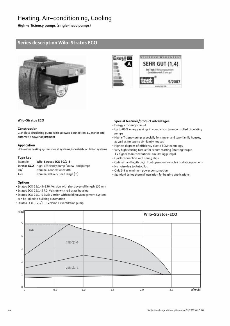
44 Subject to change without prior notice 09/2007 WILO AG
Heating, Air-conditioning, CoolingHigh-efficiency pumps (single-head pumps)
Series description Wilo-Stratos ECO
Wilo-Stratos ECO
ConstructionGlandless circulating pump with screwed connection, EC motor and automatic power adjustment
ApplicationHot-water heating systems for all systems, industrial circulation systems
Type keyExample: Wilo-Stratos ECO 30/1-3Stratos ECO High-efficiency pump (screw-end pump)30/ Nominal connection width 1-3 Nominal delivery head range [m]
Options• Stratos ECO 25/1-5-130: Version with short over-all length 130 mm• Stratos ECO 25/1-5 RG: Version with red brass housing • Stratos ECO 25/1-5 BMS: Version with Building Management System,
can be linked to building automation• Stratos ECO-L 25/1-5: Version as ventilation pump
Special features/product advantages• Energy efficiency class A• Up to 80% energy savings in comparison to uncontrolled circulating
pumps• High efficiency pump especially for single- and two-family houses,
as well as for two to six-family houses• Highest degrees of efficiency due to ECM technology• Very high starting torque for secure starting (starting torque
3 x higher than conventional circulating pumps)• Quick connection with spring clips• Optimal handling through front operation, variable installation positions• No noise due to Autopilot• Only 5.8 W minimum power consumption• Standard series thermal insulation for heating applications
0
1
2
3
4
5
H[m]
0 0,5 1,0 1,5 2,0 2,5 Q[m³/h]
BMS
25(30)1-5
25(30)1-3
Wilo-Stratos-ECO

45
Heating, Air-conditioning, CoolingHigh-efficiency pumps (single-head pumps)
Series description Wilo-Stratos ECO
Wilo Catalogue A1 - 50 Hz - Circulating Pumps in Glandless Design
Hea
ting,
Air-
cond
ition
ing,
Co
olin
gSe
cond
ary
Hot W
ater
Circ
ulat
ion
Sola
r The
rmal
, Geo
ther
mal
En
ergy
Sys
tem
sSe
rvic
e/Ac
cess
orie
s, S
yste
ms
Switc
hgea
rs a
nd C
ontr
ol
Dev
ices
Pum
p M
anag
emen
t Sys
tem
s
Equipment/function
Operating modes• Remote speed control (n=constant) (only Stratos ECO...BMS)• �p-c for constant differential pressure (only Stratos ECO...BMS)• �p-v for variable differential pressure
Manual functions• Selection of operating mode (only Stratos ECO...BMS)• Setting the differential-pressure setpoint• Setting to “Autopilot” (automatic setback operation)• Selection Pump ON/OFF (only Stratos ECO...BMS)• Selection of speed (manual speed setting) (only Stratos ECO...BMS)
Automatic functions• Stageless power adjustment depending on the operating mode• “Autopilot” automatic setback operation• Deblocking function• Soft start• Safety control
External control functions• Control input “Overriding Off” (only Stratos ECO...BMS)• Control input “Analogue In 0 - 10 V” (remote speed adjustment)
(only Stratos ECO...BMS)• Control input “Analogue In 0 - 10 V” (remote setpoint adjustment)
(only Stratos ECO...BMS)
Signal and display functions• Collective fault signal (potential-free NC contact) (only Stratos
ECO...BMS)• Fault signal light (only Stratos ECO...BMS)
Equipment/scope of delivery• Wrench attachment point on pump body• Cable entry possible on both sides• Quick connection with spring clips• Integrated air extraction fitting for automatic quick aspirator Rp 3/8
(only Stratos ECO-L)• Blocking current-proof motor• Including seals for threaded connection (loose)• Including installation and operating instructions• Including thermal insulation• Particle filter
Accessories• Screwed connections

46 Subject to change without prior notice 09/2007 WILO AG
Heating, Air-conditioning, CoolingHigh-efficiency pumps (single-head pumps)
Technical data Wilo-Stratos ECO
Wilo-Stratos ECO...
25/1-325/1-3-130
25/1-525/1-5-13025/1-5 BMS-L 25/1-5
25/1-5 RG 30/1-3 30/1-530/1-5 BMS
Approved fluids (other fluids/media on request)
Heating water (as per VDI 2035) • • • • •Water/glycol mixtures (maximum 1:1; mixtures with more than 20 % glycol content require rechecking of the pumping data)
• • • • •
Secondary hot water and water for food businesses as per TrinkwV 2001 – – – – –
Performance
Maximum delivery head [m] 2.5 5 5 2.5 5
Maximum flow volume [m3/h] 2.5 2.5 2.5 2.5 2.5
Permitted field of application
Temperature range for utilisation in heating, ventila-tion & air conditioning systems
at maximum ambient temperature +25 °C [°C]at maximum ambient temperature +40 °C [°C]
+ 15 to + 110+ 15 to + 95
Temperature range for utilisation in secondary hot water circulation systems
at maximum ambient temperature +40 °C [°C]with maximum ambient temperature +40 °C in short-term operation 2 h [°C]
–
–
–
–
–
–
–
–
–
–
Maximum permissible total hardness in secondary hot water circulation systems [°d] – – – – –
Standard version with nominal pressure, pmax [bar] 10 10 10 10 10
Special version with nominal pressure, pmax [bar] – – – – –
Pipe connections
Screwed connection Rp 1 1 1 1 1/4 1 1/4
Nominal connection diameter flange DN – – – – –
Flange for counter flange PN 6, standard version – – – – –
Flange for counter flange PN 16, special version – – – – –
Combination flange PN 6/10 for counter flange PN 6 and PN 16, standard version – – – – –
Support-bracket mounting (with horizontal shaft only), standard version – – – – –
Support-bracket mounting (with horizontal shaft only), special version – – – – –
Electrical connection
Mains connection 1~ [V], standard version 230 230 230 230 230
Mains connection 3~ [V], standard version – – – – –
Mains connection 3~ [V], with optional switching plug – – – – –
Mains frequency [Hz] 50 50 50 50 50
• = available, – = not available

47
Heating, Air-conditioning, CoolingHigh-efficiency pumps (single-head pumps)
Technical data Wilo-Stratos ECO
Wilo Catalogue A1 - 50 Hz - Circulating Pumps in Glandless Design
Hea
ting,
Air-
cond
ition
ing,
Co
olin
gSe
cond
ary
Hot W
ater
Circ
ulat
ion
Sola
r The
rmal
, Geo
ther
mal
En
ergy
Sys
tem
sSe
rvic
e/Ac
cess
orie
s, S
yste
ms
Switc
hgea
rs a
nd C
ontr
ol
Dev
ices
Pum
p M
anag
emen
t Sys
tem
s
Motor/electronics
Electromagnetic compatibility EN 61800-3
Emitted interference EN 61000-6-3
Immunity to interference EN 61000-6-2
Power electronics Pulse-pack control
Protection class IP 44 IP 44 IP 44 IP 44 IP 44
Insulation class F F F F F
Materials
Pump housing Cast iron (EN-GJL-200)
Red brass (CC 491K) as per DIN EN 1982, as
per TrinkwV 2001
Cast iron (EN-GJL-200)
Impeller Plastic (PP - 40 % GF)
Shaft Stainless steel
Bearing Metal-impregnated carbon
Minimum suction head at suction port [m]for the prevention of cavitation at water delivery temperature
50 °C 0.5 0.5 0.5 0.5 0.5
95 °C 3.0 3.0 3.0 3.0 3.0
110 °C 10.0 10.0 10.0 10.0 10.0
Wilo-Stratos ECO...
25/1-325/1-3-130
25/1-525/1-5-13025/1-5 BMS-L 25/1-5
25/1-5 RG 30/1-3 30/1-530/1-5 BMS
• = available, – = not available
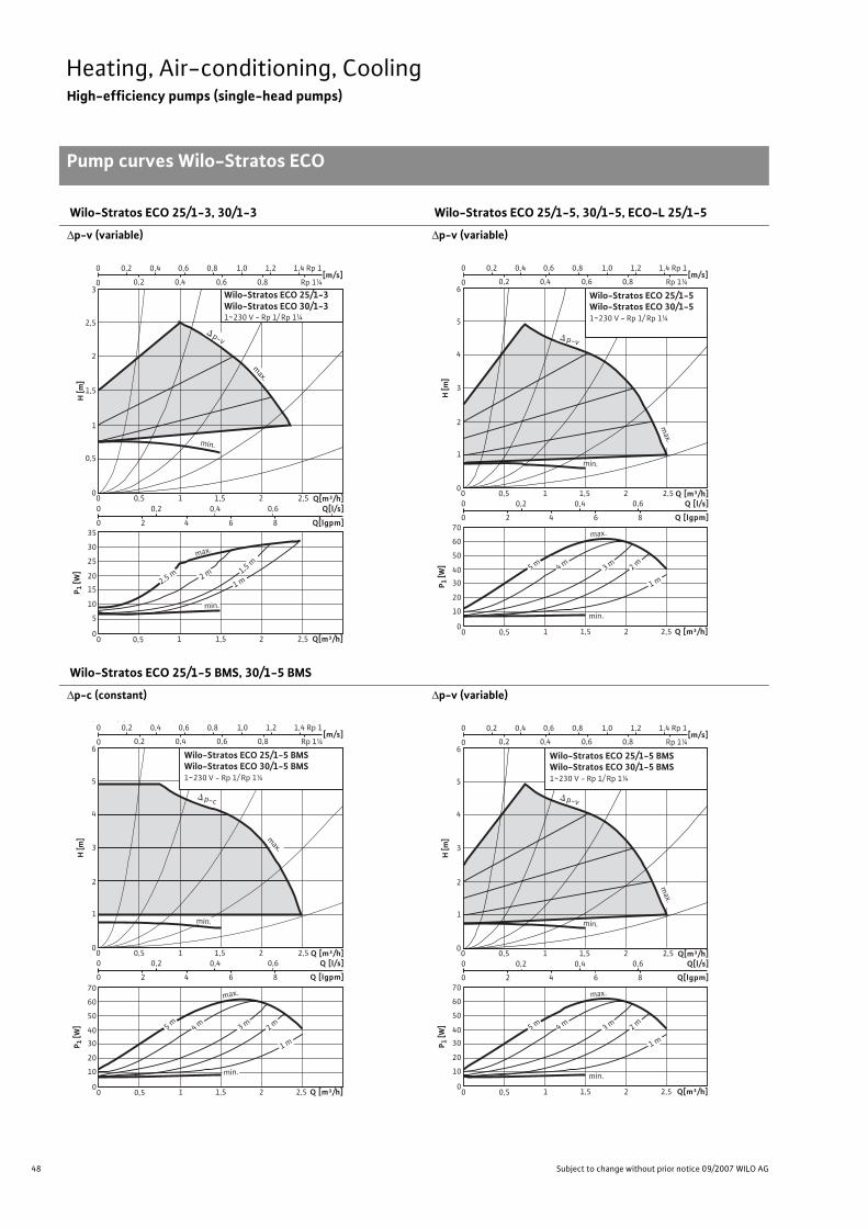
48 Subject to change without prior notice 09/2007 WILO AG
Heating, Air-conditioning, CoolingHigh-efficiency pumps (single-head pumps)
Pump curves Wilo-Stratos ECO
Wilo-Stratos ECO 25/1-3, 30/1-3 Wilo-Stratos ECO 25/1-5, 30/1-5, ECO-L 25/1-5
�p-v (variable) �p-v (variable)
Wilo-Stratos ECO 25/1-5 BMS, 30/1-5 BMS
�p-c (constant) �p-v (variable)
Pump curves
H [m
]
0
2
2,5
3
1
0,5
1,5
0 0,5 0 0,2 0,4 0,6
0 2 4 6 8
1 1,5 2 2,5
Q[m³/h]1,51 2,520 0,5
Q[m³/h]Q[l/s]
Q[lgpm]
0
20
15
10
5
25
30
35
P 1 [W
]
[m/s]0 0,8 0,2 0,4
0,2 0 0,4 0,6 0,8 1,0 1,2 1,4
0,6 Rp 1¼
Rp 1
p-v
max.
min.
Wilo-Stratos ECO 25/1-3Wilo-Stratos ECO 30/1-31~230 V - Rp 1/ Rp 1¼
max.
2 m 1,5 m
1 m
min.
2,5 m
H [m
]
0
4
5
6
2
1
3
[m/s] 0 0,8 0,2 0,4
0,2 0 0,4 0,6 0,8 1,0 1,2 1,4
0,6
0 0,5 0 0,2 0,4 0,6
0 2 4 6 8
1 1,5 2 2,5
Q [m³/h]1,51 2,520 0,5
Q [m³/h]Q [l/s]
Q [lgpm]
0
40
30
20
10
50
60
70
P 1 [W
]
Rp 1¼
Rp 1
p-v
max.
min.
Wilo-Stratos ECO 25/1-5Wilo-Stratos ECO 30/1-51~230 V - Rp 1/ Rp 1¼
max.
4 m 3 m 2 m
1 m
5 m
min.
max.
H [m
]
0
4
5
6
2
1
3
[m/s] 0 0,8 0,2 0,4
0,2 0 0,4 0,6 0,8 1,0 1,2 1,4
0,6
0 0,5 0 0,2 0,4 0,6
0 2 4 6 8
1 1,5 2 2,5
[m³/h] 1,5 1 2,5 2 0 0,5
[m³/h] [l/s]
[lgpm]
0
40
30
20
10
50
60
70
P 1 [W
]
Q
4 m
3 m
2 m
1 m
p-c
max.
min.
min.
5 m
Rp 1¼
Rp 1
Wilo-Stratos ECO 25/1-5 BMS1 ~ 230 V - Rp 1/ Rp 1¼
H [m
]
0
4
5
6
2
1
3
[m/s] 0 0,8 0,2 0,4
0,2 0 0,4 0,6 0,8 1,0 1,2 1,4
0,6
0 0,50 0,2 0,4 0,6
0 2 4 6 8
1 1,5 2 2,5
Q [m³/h]1,51 2,520 0,5
Q [m³/h]Q [l/s]
Q [lgpm]
0
40
30
20
10
50
60
70
P 1 [W
]
Rp 1¼
Rp 1
max.
4 m 3 m 2 m
1 m
p-c
max.
min.
min.
5 m
Wilo-Stratos ECO 25/1-5 BMSWilo-Stratos ECO 30/1-5 BMS1~230 V - Rp 1/ Rp 1¼
H [m
]
0
4
5
6
2
1
3
[m/s] 0 0,8 0,2 0,4
0,2 0 0,4 0,6 0,8 1,0 1,2 1,4
0,6
0 0,5 0 0,2 0,4 0,6
0 2 4 6 8
1 1,5 2 2,5
Q[m³/h]1,51 2,520 0,5
Q[m³/h]Q[l/s]
Q[lgpm]
0
40
30
20
10
50
60
70
P 1 [W
]
Rp 1¼
Rp 1
p-v
max.
min.
max.
4 m 3 m 2 m
1 m
5 m
min.
Wilo-Stratos ECO 25/1-5 BMSWilo-Stratos ECO 30/1-5 BMS1~230 V - Rp 1/ Rp 1¼
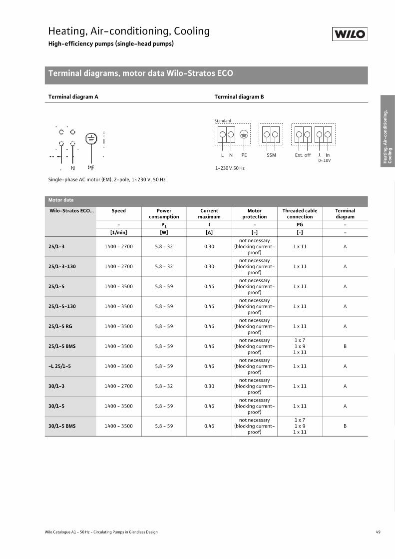
49
Heating, Air-conditioning, CoolingHigh-efficiency pumps (single-head pumps)
Terminal diagrams, motor data Wilo-Stratos ECO
Wilo Catalogue A1 - 50 Hz - Circulating Pumps in Glandless Design
Hea
ting,
Air-
cond
ition
ing,
Co
olin
gSe
cond
ary
Hot W
ater
Circ
ulat
ion
Sola
r The
rmal
, Geo
ther
mal
En
ergy
Sys
tem
sSe
rvic
e/Ac
cess
orie
s, S
yste
ms
Switc
hgea
rs a
nd C
ontr
ol
Dev
ices
Pum
p M
anag
emen
t Sys
tem
s
Terminal diagram A Terminal diagram B
Single-phase AC motor (EM), 2-pole, 1~230 V, 50 Hz
Motor data
Wilo-Stratos ECO... Speed Power consumption
Current maximum
Motor protection
Threaded cable connection
Terminal diagram
- P1 I - PG -[1/min] [W] [A] [-] [-] -
25/1-3 1400 - 2700 5.8 - 32 0.30not necessary
(blocking current-proof)
1 x 11 A
25/1-3-130 1400 - 2700 5.8 - 32 0.30not necessary
(blocking current-proof)
1 x 11 A
25/1-5 1400 - 3500 5.8 - 59 0.46not necessary
(blocking current-proof)
1 x 11 A
25/1-5-130 1400 - 3500 5.8 - 59 0.46not necessary
(blocking current-proof)
1 x 11 A
25/1-5 RG 1400 - 3500 5.8 - 59 0.46not necessary
(blocking current-proof)
1 x 11 A
25/1-5 BMS 1400 - 3500 5.8 - 59 0.46not necessary
(blocking current-proof)
1 x 71 x 9
1 x 11B
-L 25/1-5 1400 - 3500 5.8 - 59 0.46not necessary
(blocking current-proof)
1 x 11 A
30/1-3 1400 - 2700 5.8 - 32 0.30not necessary
(blocking current-proof)
1 x 11 A
30/1-5 1400 - 3500 5.8 - 59 0.46not necessary
(blocking current-proof)
1 x 11 A
30/1-5 BMS 1400 - 3500 5.8 - 59 0.46not necessary
(blocking current-proof)
1 x 71 x 9
1 x 11B
0~10V
Standard
L N PE SSM In Ext. off
1~230 V, 50 Hz

50 Subject to change without prior notice 09/2007 WILO AG
Heating, Air-conditioning, CoolingHigh-efficiency pumps (single-head pumps)
Dimensions, weights Wilo-Stratos ECO
Dimension drawing A Dimension drawing B
Dimension drawing C Dimension drawing D
Dimensions, weights
Wilo-Stratos ECO... Pipe connection
Thread Dimensions Weight about
Dimension drawing
Rp G l0 l1 l3 l4 l5 a a2 b1 b2 b3 b4 b5 - -[-] [-] [mm] [kg] [-]
25/1-3 1 1 1/2 180 96 90 78 50 60 32.5 133 93.5 61 73 69 2.6 A25/1-3-130 1 1 1/2 130 96 90 78 50 60 32.5 133 93.5 61 73 69 2.5 A25/1-5 1 1 1/2 180 96 90 78 50 60 32.5 133 93.5 61 73 69 2.6 A25/1-5-130 1 1 1/2 130 96 65 78 50 60 32.5 133 93.5 61 73 69 2.5 B25/1-5 RG 1 1 1/2 180 96 90 78 50 60 32.5 133 93.5 61 73 69 2.6 A25/1-5 BMS 1 1 1/2 180 96 90 78 50 60 32.5 185 93.5 78 73 94 2.9 D-L 25/1-5 1 1 1/2 180 100 90 78 50 62 28.0 129 93.5 61 73 69 3.2 C30/1-3 1 1/4 2 180 96 90 78 50 60 32.5 133 93.5 61 73 69 2.7 A30/1-5 1 1/4 2 180 96 90 78 50 60 32.5 133 93.5 61 73 69 2.7 A30/1-5 BMS 1 1/4 2 180 96 90 78 50 60 32.5 185 93.5 78 73 94 2.9 D
G
a
b1
b3
b2 a2
b5
I4 I5
I1
I 0
l 3
b 4 b 1b 3
b 5
b 2
b4I4 I5
I1
I 0l 3
a
a2
G
b1
b2
48 57
71
43 47,75
G
a2
a
b3 b5
I4
I5
I1
I 0l 3
b 4
b1
b3
b2
b5 G
a
a2
I4 I5
I1
I 0
l 3
b 4

Wilo-Stratos ECO high-efficiency pump.
*With a grade of 1.3, the Wilo-Stratos ECO is even a test winner in terms of energy efficiency:• 23 % lower energy consumption than the runner-up.• savings of up to 3,000 Euro in 20 years compared to uncontrolled heating pumps.
Very good? We call this Pumpen Intelligenz.
www.wilo.com
Best in energy saving.*
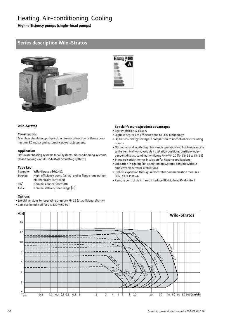
52 Subject to change without prior notice 09/2007 WILO AG
Heating, Air-conditioning, CoolingHigh-efficiency pumps (single-head pumps)
Series description Wilo-Stratos
Wilo-Stratos
ConstructionGlandless circulating pump with screwed connection or flange con-nection, EC motor and automatic power adjustment.
ApplicationHot-water heating systems for all systems, air-conditioning systems, closed cooling circuits, industrial circulating systems.
Type keyExample: Wilo-Stratos 30/1-12Stratos High-efficiency pump (screw-end or flange-end pump),
electronically controlled30/ Nominal connection width 1-12 Nominal delivery head range [m]
Options• Special versions for operating pressure PN 16 (at additional charge)• Can also be utilised for 1 x 230 V/60 Hz
Special features/product advantages• Energy efficiency class A• Highest degrees of efficiency due to ECM technology• Up to 80% energy savings in comparison to uncontrolled circulating
pumps• Optimum handling through front-side operation and front-side access
to the terminal room, variable installation positions, position-inde-pendent display, combination flange PN 6/PN 10 (for DN 32 to DN 65)
• Standard series thermal insulation for heating applications• Utilisation in cooling/air-conditioning systems possible without
ambient temperature restrictions• System expansion through retrofittable communication modules
LON, CAN, PLR, etc.• Remote control via infrared interface (IR-Module/ IR-Monitor)
Q[m³/h]0,1 0,2 0,3 0,4 0,5 0,6 0,8 1 2 3 4 5 6 8 10 20 30 40 50 60 80 100
H[m]
0
2
4
6
8
10
12
14
65/1-9
30/1-1240(50)/1-8
80(100)/1-12
Wilo-Stratos
32/1-12
25(30)/1-8
40/1-425(30)/1-6
50/1-965/1-12
40/1-12
50/1-12
53
Heating, Air-conditioning, CoolingHigh-efficiency pumps (single-head pumps)
Series description Wilo-Stratos
Wilo Catalogue A1 - 50 Hz - Circulating Pumps in Glandless Design
Hea
ting,
Air-
cond
ition
ing,
Co
olin
gSe
cond
ary
Hot W
ater
Circ
ulat
ion
Sola
r The
rmal
, Geo
ther
mal
En
ergy
Sys
tem
sSe
rvic
e/Ac
cess
orie
s, S
yste
ms
Switc
hgea
rs a
nd C
ontr
ol
Dev
ices
Pum
p M
anag
emen
t Sys
tem
s
Equipment/function
Operating modes• Manual control mode (n=constant)• �p-c for constant differential pressure • �p-v for variable differential pressure• �p-T for temperature-controlled differential pressure (programma-
ble via IR-Module, IR-Monitor, LON or CAN)
Manual functions• Setting the operating mode• Setting the differential-pressure setpoint• Setting to “Autopilot” (automatic setback operation)• Setting the pump to ON/OFF • Setting the speed (manual setting mode)
Automatic functions• Stageless power adjustment depending on the operating mode• “Autopilot” automatic setback operation• Deblocking function• Soft start• Full motor protection with integrated trip electronics
External control functions• Control input “Overriding Off” (possible with Stratos IF-Modules)• Control input “Overriding Min” (possible with Stratos IF-Modules)• Control input “Analogue In 0 - 10 V” (remote speed adjustment)
(possible with Stratos IF-Modules)• Control input “Analogue In 0 - 10 V” (remote setpoint adjustment)
(possible with Stratos IF-Modules)
Signal and display functions• Collective fault signal (potential-free NC contact)• Individual run signal (potential-free NO contact) (possible with
Stratos IF-Modules)• Fault signal light• LC display for showing pump data and fault codes
Data exchange• Infrared interface for wireless data exchange with IR-Module/IR-
Monitor (see IR-Module/IR-Monitor Function table)• Serial digital PLR interface for connection to BA via Wilo interface
converter or company-specific coupling module (possible with Stratos IF-Modules)
• Serial digital LON interface for connection to a LONWorks network (possible with Stratos IF-Modules)
• Serial digital CAN interface for connection to a CAN bus system (possible with Stratos IF-Modules)
Dual pump management (twin-head pump or 2 x single-head pump)• Main/standby operation (automatic fault-actuated switchover/time-
sensitive pump alteration): Various combinations with Stratos IF-modules (accessory) possible
• Parallel operation (efficiency-optimised peak-load cut-in and out): Various combinations with Stratos IF-Modules (accessory) possible
Equipment/scope of delivery• Wrench attachment point at pump body (for threaded pipe union
pumps with P2 < 100 W)• Plug-in slot for optional expansion with Wilo-IF-Modules• Including seals for threaded connection (loose)• Including installation and operating instructions• Including thermal insulation• Including washers for flange bolts (for nominal connection widths
DN 32 - DN 65)
Accessories• Screwed connections with screw thread• Cold water insulation for pumps Wilo-Climaform• IR-Module• IR-Monitor• IF-Modules Stratos:
PLR, LON, CAN, Ext. Off, Ext. Min., SBM, Ext.Aus/SBM• Analogue interface converter AnaCon• Digital interface converter DigiCon/DigiCon-A

54 Subject to change without prior notice 09/2007 WILO AG
Heating, Air-conditioning, CoolingHigh-efficiency pumps (single-head pumps)
Technical data Wilo-Stratos
Wilo-Stratos
25/1-6 25/1-8 30/1-6 30/1-8 30/1-12 32/1-12 40/1-4 40/1-8 40/1-12
Approved fluids (other fluids on request)
Heating water (as per VDI 2035) • • • • • • • • •Water/glycol mixtures (maximum 1:1; mixtures with more than 20 % glycol content require rechecking of the pumping data)
• • • • • • • • •
Secondary hot water and water for food busi-nesses as per TrinkwV 2001 – – – – – – – – –
Performance
Maximum delivery head [m] 6 7 6 7 11 9 5 8 12
Maximum flow volume [m3/h] 7 8 7 8 10 13 11 13 21
Permitted field of application
Temperature range for utilisation in heating, ven-tilation & air conditioning systems
at maximum ambient temperature +25 °C [°C]at maximum ambient temperature +40 °C [°C]
–- 10 to + 110
Temperature range for utilisation in secondary hot water circulation systems
at maximum ambient temperature +40 °C [°C]at maximum ambient temperature +40 °C in short-term operation 2 h [°C]
–
–
–
–
–
–
–
–
–
–
–
–
–
–
–
–
–
–
Maximum permissible total hardness in secondary hot water-circulation systems [°d] – – – – – – – – –
Standard version with nominal pressure, pmax [bar] 6/10 6/10 6/10 6/10 6/10 6/10 6/10 6/10 6/10
Special version with nominal pressure, pmax [bar] 16 16 16 16 16 16 16 16 16
Pipe connections
Screwed connection Rp 1 1 1 1/4 1 1/4 1 1/4 – – – –
Nominal connection diameter flange DN – – – – – 32 40 40 40
Flange for counter flange PN 6, standard version – – – – – – – – –
Flange for counter flange PN 16, special version – – – – – • • • •Combination flange PN 6/10 for counter flange PN 6 and PN 16, standard version – – – – – • • • •
Support-bracket mounting (with horizontal shaft only), standard version – – – – – – – – –
Support-bracket mounting (with horizontal shaft only), special version – – – – – – – – –
Electrical connection
Mains connection 1~ [V], standard version 230 230 230 230 230 230 230 230 230
Mains connection 3~ [V], standard version 230 230 230 230 230 230 230 230 230
Mains connection 3~ [V], with optional switching plug – – – – – – – – –
Mains frequency [Hz] 50/60 50/60 50/60 50/60 50/60 50/60 50/60 50/60 50/60
• = available, – = not available
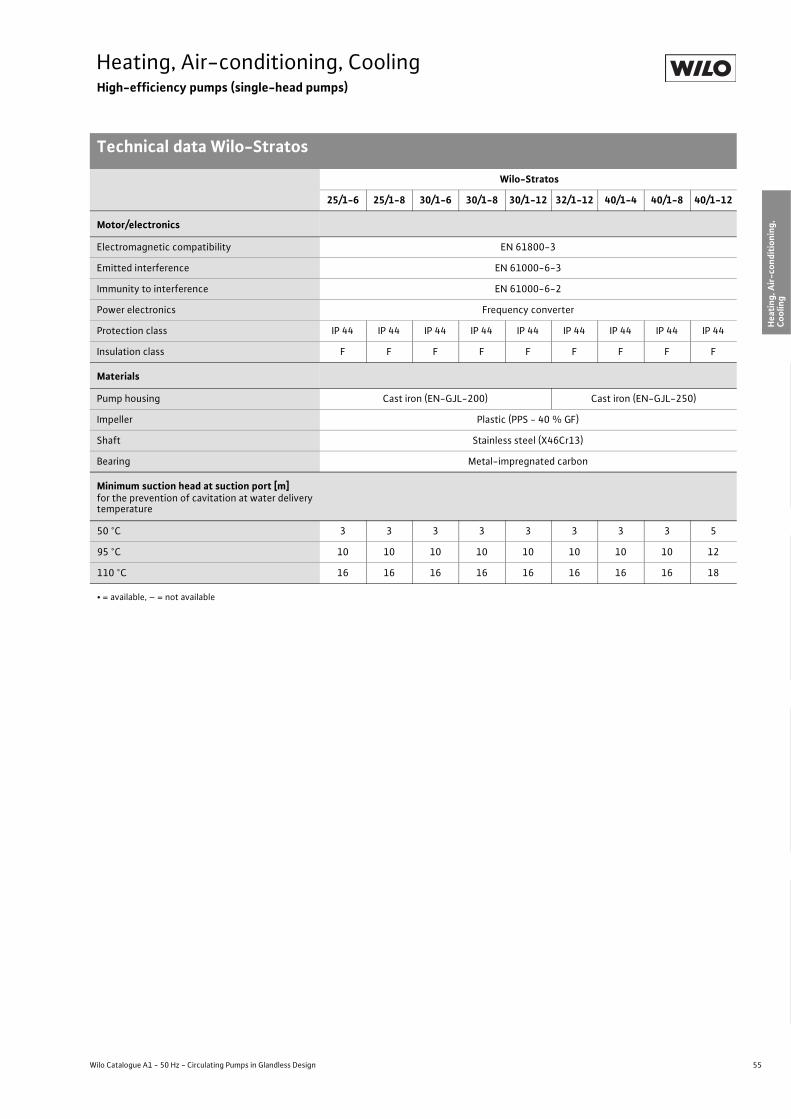
55
Heating, Air-conditioning, CoolingHigh-efficiency pumps (single-head pumps)
Technical data Wilo-Stratos
Wilo Catalogue A1 - 50 Hz - Circulating Pumps in Glandless Design
Hea
ting,
Air-
cond
ition
ing,
Co
olin
gSe
cond
ary
Hot W
ater
Circ
ulat
ion
Sola
r The
rmal
, Geo
ther
mal
En
ergy
Sys
tem
sSe
rvic
e/Ac
cess
orie
s, S
yste
ms
Switc
hgea
rs a
nd C
ontr
ol
Dev
ices
Pum
p M
anag
emen
t Sys
tem
s
Motor/electronics
Electromagnetic compatibility EN 61800-3
Emitted interference EN 61000-6-3
Immunity to interference EN 61000-6-2
Power electronics Frequency converter
Protection class IP 44 IP 44 IP 44 IP 44 IP 44 IP 44 IP 44 IP 44 IP 44
Insulation class F F F F F F F F F
Materials
Pump housing Cast iron (EN-GJL-200) Cast iron (EN-GJL-250)
Impeller Plastic (PPS - 40 % GF)
Shaft Stainless steel (X46Cr13)
Bearing Metal-impregnated carbon
Minimum suction head at suction port [m]for the prevention of cavitation at water delivery temperature
50 °C 3 3 3 3 3 3 3 3 5
95 °C 10 10 10 10 10 10 10 10 12
110 °C 16 16 16 16 16 16 16 16 18
Wilo-Stratos
25/1-6 25/1-8 30/1-6 30/1-8 30/1-12 32/1-12 40/1-4 40/1-8 40/1-12
• = available, – = not available

56 Subject to change without prior notice 09/2007 WILO AG
Heating, Air-conditioning, CoolingHigh-efficiency pumps (single-head pumps)
Technical data Wilo-Stratos
Wilo-Stratos
50/1-8 50/1-9 50/1-12 65/1-9 65/1-12 80/1-12 100/1-12
Approved fluids (other fluids on request)
Heating water (as per VDI 2035) • • • • • • •Water/glycol mixtures (maximum 1:1; mixtures with more than 20 % glycol content require rechecking of the pumping data)
• • • • • • •
Secondary hot water and water for food businesses as per TrinkwV 2001 – – – – – – –
Performance
Maximum delivery head [m] 8 9 11 10 11 13 13
Maximum flow volume [m3/h] 13 24 29 29 41 61 61
Permitted field of application
Temperature range for utilisation in heating, ventila-tion & air conditioning systems
at maximum ambient temperature +25 °C [°C]at maximum ambient temperature +40 °C [°C]
–- 10 to + 110
Temperature range for utilisation in secondary hot water circulation systems
at maximum ambient temperature +40 °C [°C]at maximum ambient temperature +40 °C in short-term operation 2 h [°C]
–
–
–
–
–
–
–
–
–
–
–
–
–
–
Maximum permissible total hardness in secondary hot water-circulation systems [°d] – – – – – – –
Standard version with nominal pressure, pmax [bar] 6/10 6/10 6/10 6/10 6/10 6 6
Special version with nominal pressure, pmax [bar] 16 16 16 16 16 10, 16
Pipe connections
Screwed connection Rp – – – – – – –
Nominal connection diameter flange DN 50 50 50 65 65 80 100
Flange for counter flange PN 6, standard version – – – – – • •Flange for counter flange PN 16, special version • • • • • • •Combination flange PN 6/10 for counter flange PN 6 and PN 16, standard version • • • • • – –
Support-bracket mounting (with horizontal shaft only), standard version – – – – – – –
Support-bracket mounting (with horizontal shaft only), special version – – – – – – –
Electrical connection
Mains connection 1~ [V], standard version 230 230 230 230 230 230 230
Mains connection 3~ [V], standard version 230 230 230 230 230 230 230
Mains connection 3~ [V], with optional switching plug – – – – – – –
Mains frequency [Hz] 50/60 50/60 50/60 50/60 50/60 50/60 50/60
• = available, – = not available

57
Heating, Air-conditioning, CoolingHigh-efficiency pumps (single-head pumps)
Technical data Wilo-Stratos
Wilo Catalogue A1 - 50 Hz - Circulating Pumps in Glandless Design
Hea
ting,
Air-
cond
ition
ing,
Co
olin
gSe
cond
ary
Hot W
ater
Circ
ulat
ion
Sola
r The
rmal
, Geo
ther
mal
En
ergy
Sys
tem
sSe
rvic
e/Ac
cess
orie
s, S
yste
ms
Switc
hgea
rs a
nd C
ontr
ol
Dev
ices
Pum
p M
anag
emen
t Sys
tem
s
Motor/electronics
Electromagnetic compatibility EN 61800-3
Emitted interference EN 61000-6-3
Immunity to interference EN 61000-6-2
Power electronics Frequency converter
Protection class IP 44 IP 44 IP 44 IP 44 IP 44 IP 44 IP 44
Insulation class F F F F F F F
Materials
Pump housing Cast iron (EN-GJL-250)
Impeller Plastic (PPS - 40% GF) Plastic (PP - 50% GF)
Shaft Stainless steel (X46Cr13)
Bearing Metal-impregnated carbon
Minimum suction head at suction port [m]for the prevention of cavitation at water delivery temperature
50 °C 3 5 5 5 7 7 7
95 °C 10 12 12 12 15 15 15
110 °C 16 18 18 18 23 23 23
Wilo-Stratos
50/1-8 50/1-9 50/1-12 65/1-9 65/1-12 80/1-12 100/1-12
• = available, – = not available

58 Subject to change without prior notice 09/2007 WILO AG
Heating, Air-conditioning, CoolingHigh-efficiency pumps (single-head pumps)
Pump curves Wilo-Stratos
Wilo-Stratos 25/1-6, 30/1-6
�p-c (constant)
�p-v (variable)
Wilo-Stratos 25/1-8, 30/1-8
�p-c (constant)
�p-v (variable)
Q
min.
max.
H [m
]
0
4
5
7
6
2
1
3
Wilo-Stratos 25/1-6 Wilo-Stratos 30/1-6
1 ~ 230 V - Rp1 / Rp1¼
[m/s]
v210 2,5 31,5 3,50,5
0 0,5 1 21,5
[m³/h]640 2 5 731
[m³/h]640 2 5 731
[l/s]
[lgpm]
2
10 20
1,510,5
0
0
0
80
60
40
20
100
P 1 [W
]
1 m
2 m
3 m4 m5 m6 mmax.
min.
max.
p-c
Rp 1¼
Rp 1
Q
min.
max.
H [m
]
0
4
5
7
6
2
1
3
Wilo-Stratos 25/1-6 Wilo-Stratos 30/1-6
1 ~ 230 V - Rp1 / Rp1¼
[m³/h]640 2 5 731
[m³/h]640 2 5 731
[l/s]
[lgpm]
2
10 20
1,510,5
0
0
0
80
60
40
20
100
P 1 [W
] 6 m 5 m 4 m3 m
2 m
p-v
min.
max.
[m/s]
v210 2,5 31,5 3,50,5
0 0,5 1 21,5 Rp 1¼
Rp 1
0
4
5
7
6
8
2
1
3
H [m
]
Q
[m³/h][l/s]
[lgpm]
P 1 [W
]
0
80
60
40
20
100
120
140
Wilo-Stratos 25/1-8 Wilo-Stratos 30/1-8 1 ~ 230 V - Rp 1 / Rp 1 ¼
6 8 4 0 2 5 7 3 1
[m³/h]6 8 4 0 2 5 7 3 1
2
10 20
1,5 1 0,5
0
0
[m/s] 2 1 0 2,5 1,5 0,5
v 2 1 0 2,5 3 4 1,5 Rp 1
Rp 1 ¼
3,5 0,5
max.
max.
1 m 2 m
3 m 4 m 5 m 6 m 7 m
min.
p-c
max.
min.
0
4
5
7
6
8
2
1
3
H [m
]
Q
[l/s]
[lgpm]
P 1 [W
]
0
80
60
40
20
100
120
140
2
10 20
1,5 1 0,5
0
0
[m/s] 2 1 0 2,5 1,5 0,5
v 2 1 0 2,5 3 4 1,5 Rp 1
Rp 1 ¼
3,5 0,5
Wilo-Stratos 25/1-8 Wilo-Stratos 30/1-8 1 ~ 230 V - Rp 1 / Rp 1 ¼
[m³/h] 6 8 4 0 2 5 7 3 1
[m³/h] 6 8 4 0 2 5 7 3 1
max.
min. 2 m 3 m 4 m 5 m
6 m 7 m
min.
max.
p-v

59
Heating, Air-conditioning, CoolingHigh-efficiency pumps (single-head pumps)
Pump curves Wilo-Stratos
Wilo Catalogue A1 - 50 Hz - Circulating Pumps in Glandless Design
Hea
ting,
Air-
cond
ition
ing,
Co
olin
gSe
cond
ary
Hot W
ater
Circ
ulat
ion
Sola
r The
rmal
, Geo
ther
mal
En
ergy
Sys
tem
sSe
rvic
e/Ac
cess
orie
s, S
yste
ms
Switc
hgea
rs a
nd C
ontr
ol
Dev
ices
Pum
p M
anag
emen
t Sys
tem
s
Wilo-Stratos 30/1-12
�p-c (constant)
�p-v (variable)
Wilo-Stratos 32/1-12
�p-c (constant)
�p-v (variable)
v0 1 2 31,50,5 2,5 3,5 [m/s]
0
8
10
12
14
4
2
6
H [m
]
[m³/h][l/s]
[lgpm]
P 1 [W
]
0
250
200
100
150
50
300
350
Wilo-Stratos 30/1-121 ~ 230 V - Rp 1 ¼
80 4 1062
[m³/h]80 4 1062
1 1,5 2 32,5
10 20 30
0,5
0
0
Qmax.
max.
10 m 8 m 6 m 4 m
2 m
1 mmin.
min.
p-c
max.
v0 1 2 31,50,5 2,5 3,5 [m/s]
0
8
10
12
14
4
2
6
H [m
][m³/h]
[l/s]
[lgpm]
P 1 [W
]
0
250
200
100
150
50
300
350
Wilo-Stratos 30/1-121 ~ 230 V - Rp 1 ¼
80 4 1062
[m³/h]80 4 1062
1 1,5 2 32,5
10 20 30
0,5
0
0
Qmax.
10 m 8 m 6 m 4 m
min.
min.
p-v
max.
v0 1 2 3 41,50,5 2,5 3,5 [m/s]
0
8
10
4
2
6
H [m
]
[m³/h][l/s]
[lgpm]
P 1 [W
]
0
250
200
100
150
50
300
350
Wilo-Stratos 32/1-121 ~ 230 V - DN 32
80 4 10 1262
[m³/h]80 4 10 1262
1 1,5 2 32,5 3,5
10 20 30 40
0,5
0
0
Qmax.
max.
8 m 6 m 4 m
2 m
9 m
1 mmin.
min.
p-c
max.
v0 1 2 3 41,50,5 2,5 3,5 [m/s]
0
8
10
4
2
6
H [m
]
[m³/h][l/s]
[lgpm]
P 1 [W
]
0
250
200
100
150
50
300
350
Wilo-Stratos 32/1-121 ~ 230 V - DN 32
80 4 10 1262
[m³/h]80 4 10 1262
1 1,5 2 32,5 3,5
10 20 30 40
0,5
0
0
Qmax.
min.
8 m 7 m 6 m 5 m 4 m
min.
p-v
max.
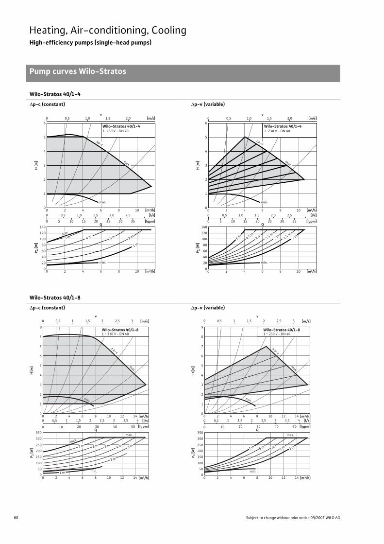
60 Subject to change without prior notice 09/2007 WILO AG
Heating, Air-conditioning, CoolingHigh-efficiency pumps (single-head pumps)
Pump curves Wilo-Stratos
Wilo-Stratos 40/1-4
�p-c (constant)
�p-v (variable)
Wilo-Stratos 40/1-8
�p-c (constant)
�p-v (variable)
0 0.5 1.0 1.5 2.0 [m/s]
0
1
2
3
4
5
6
0 2 4 6 8 10 [m³/h]
H [m
]
0 0.5 1.0 1.5 2.0 2.5 [l/s]
0 5 10 15 20 25 30 35 [Igpm]
0
20
40
60
80
100
120
140
0 2 4 6 8 10 [m³/h]
P 1 [W
]
v
Q
Wilo-Stratos 40/1-41~230 V - DN 40
max.
min.
min.
5 m 4 m 3 m 2 m
1 m
max.
Δp-c
0 0.5 1.0 1.5 2.0 [m/s]
0
1
2
3
4
5
6
0 2 4 6 8 10 [m³/h]
H [m
]
0 0.5 1.0 1.5 2.0 2.5 [l/s]
0 5 10 15 20 25 30 35 [Igpm]
0
20
40
60
80
100
120
140
0 2 4 6 8 10 [m³/h]
P 1 [W
]
v
Q
Wilo-Stratos 40/1-41~230 V - DN 40
max.
min.
min.
5 m 4.5 m4 m 3 m 2 m3.5 m
2.5 m
Δp-v
0
8
9
4
2
6
7
3
1
5
H [m
]
[m³/h][l/s]
[lgpm]
Wilo-Stratos 40/1-81 ~ 230 V - DN 40
1280 4 10 1462
[m³/h]1280 4 10 1462
1,51 2,52 43,53
10 20 30 40 50
0,5
0
0
Q
P 1 [W
]
0
250
200
100
150
50
300
350
v0 1 2 31,50,5 2,5 [m/s]
max.
max.
7 m 6 m 5 m 4 m 3 m
2 m
1 m min.
p-c
min.
max.
0
8
9
4
2
6
7
3
1
5
H [m
]
[m³/h][l/s]
[lgpm]
Wilo-Stratos 40/1-81 ~ 230 V - DN 40
1280 4 10 1462
[m³/h]1280 4 10 1462
1,51 2,52 43,53
10 20 30 40 50
0,5
0
0
Q
P 1 [W
]
0
250
200
100
150
50
300
350
v0 1 2 31,50,5 2,5 [m/s]
min.
max.
7 m 6 m 5 m 4 m 3 m
min.
p-v
max.
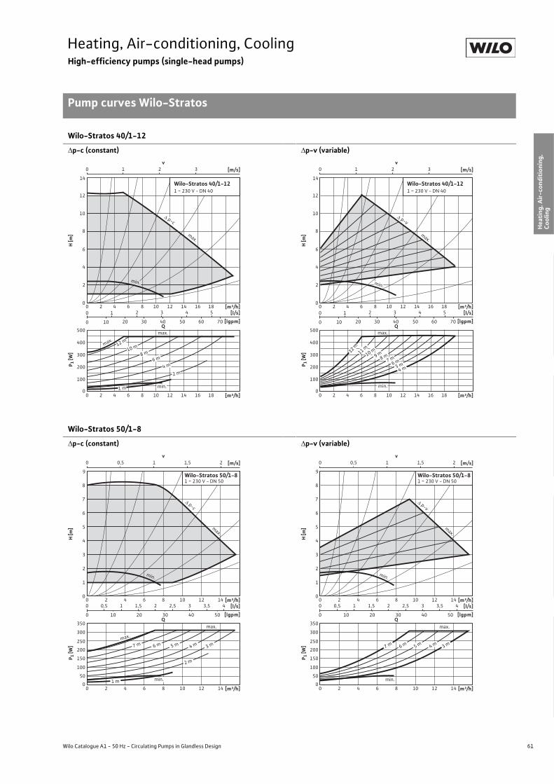
61
Heating, Air-conditioning, CoolingHigh-efficiency pumps (single-head pumps)
Pump curves Wilo-Stratos
Wilo Catalogue A1 - 50 Hz - Circulating Pumps in Glandless Design
Hea
ting,
Air-
cond
ition
ing,
Co
olin
gSe
cond
ary
Hot W
ater
Circ
ulat
ion
Sola
r The
rmal
, Geo
ther
mal
En
ergy
Sys
tem
sSe
rvic
e/Ac
cess
orie
s, S
yste
ms
Switc
hgea
rs a
nd C
ontr
ol
Dev
ices
Pum
p M
anag
emen
t Sys
tem
s
Wilo-Stratos 40/1-12
�p-c (constant)
�p-v (variable)
Wilo-Stratos 50/1-8
�p-c (constant)
�p-v (variable)
v0 1 2 3 [m/s]
0
8
10
12
14
4
2
6
H [m
]
[m³/h][l/s]
[lgpm]
P 1 [W
]
0
300
200
100
400
500
Wilo-Stratos 40/1-121 ~ 230 V - DN 40
12 16 1880 4 10 1462
12 16 1880 4 10 1462 [m³/h]
2 3 4 5
10 20 30 40 50 60 70
1
0
0
Qmax.
8 m10 m
6 m
4 m
2 m
1 m
max.
min.
12 m
p-c
min.
max.
v0 1 2 3 [m/s]
0
8
10
12
14
4
2
6
H [m
]
[l/s]
[lgpm]
P 1 [W
]
0
300
200
100
400
500
Wilo-Stratos 40/1-121 ~ 230 V - DN 40
2 3 4 5
10 20 30 40 50 60 70
1
0
0
Q
[m³/h]12 16 1880 4 10 1462
12 16 1880 4 10 1462 [m³/h]
max.
9 m8 m10 m12 m
11 m
7 m6 m
5 m4 m
min.
p-v
max.
min.
v0 1 21,50,5 [m/s]
0
8
9
4
2
6
7
3
1
5
H [m
]
[m³/h][l/s]
[lgpm]
P 1 [W
]
0
250
200
100
150
50
300
350
Wilo-Stratos 50/1-81 ~ 230 V - DN 50
80 4 10 12 1462
[m³/h]80 4 10 12 1462
1 1,5 2 3 42,5 3,5
10 20 30 40 50
0,5
0
0
Q
min.
max.
7 m 6 m 5 m 4 m 3 m
2 m
1 m
max.
min.
p-c
max.
v0 1 21,50,5 [m/s]
0
8
9
4
2
6
7
3
1
5
H [m
]
[m³/h][l/s]
[lgpm]
P 1 [W
]
0
250
200
100
150
50
300
350
Wilo-Stratos 50/1-81 ~ 230 V - DN 50
80 4 10 12 1462
[m³/h]80 4 10 12 1462
1 1,5 2 3 42,5 3,5
10 20 30 40 50
0,5
0
0
Q
min.
7 m 6 m 5 m 4 m 3 m
max.
min.
p-v
max.

62 Subject to change without prior notice 09/2007 WILO AG
Heating, Air-conditioning, CoolingHigh-efficiency pumps (single-head pumps)
Pump curves Wilo-Stratos
Wilo-Stratos 50/1-9
�p-c (constant)
�p-v (variable)
Wilo-Stratos 50/1-12
�p-c (constant)
�p-v (variable)
v0 1 2 3 [m/s]
0
8
10
12
4
2
6
H [m
]
[m³/h][l/s]
[lgpm]
P 1 [W
]
0
350
10050
400450
200150
250300
12 16 18 20 2280 4 10 1462
12 16 18 20 2280 4 10 1462
2 3 4 5 6
10 20 30 40 50 60 70 80
1
0
0
Q
[m³/h]
Wilo-Stratos 50/1-91 ~ 230 V - DN 50
max.8 m
7 m
min.
6 m5 m
4 m3 m
2 m
1m
min.
p-c
max.
v0 1 2 3 [m/s]
0
8
10
12
4
2
6
H [m
]
[l/s]
[lgpm]
P 1 [W
]
0
350
10050
400450
200150
250300
2 3 4 5 6
10 20 30 40 50 60 70 80
1
0
0
Q
Wilo-Stratos 50/1-91 ~ 230 V - DN 50
[m³/h]12 16 18 20 2280 4 10 1462
12 16 18 20 2280 4 10 1462 [m³/h]
min.
max.9 m
8 m7 m
6 m5 m
4 m3 m
min.
p-v
max.
v0 1 32 [m/s]
0
12
14
4
2
8
10
6
H [m
]
[m³/h][l/s]
[lgpm]
P 1 [W
]
0
500
400
200
300
100
600
700
100 15 20 255
[m³/h]100 15 20 255
2 3 4 65 7
20 40 60 80
1
0
0
Q
Wilo-Stratos 50/1-121 ~ 230 V - DN 50
9 m7 m
max.
min.
6 m5 m
4 m3 m
2 m
1m
max.
11 m10 m
8 m
min.
p-c
max.
v0 1 32 [m/s]
0
12
14
4
2
8
10
6
H [m
]
[m³/h][l/s]
[lgpm]
P 1 [W
]
0
500
400
200
300
100
600
700
100 15 20 255
[m³/h]100 15 20 255
2 3 4 65 7
20 40 60 80
1
0
0
Q
Wilo-Stratos 50/1-121 ~ 230 V - DN 50
min.
max.
11 m
10 m9 m
8 m7 m
6 m5 m
4 m
min.
p-v
max.
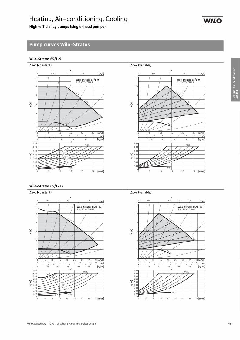
63
Heating, Air-conditioning, CoolingHigh-efficiency pumps (single-head pumps)
Pump curves Wilo-Stratos
Wilo Catalogue A1 - 50 Hz - Circulating Pumps in Glandless Design
Hea
ting,
Air-
cond
ition
ing,
Co
olin
gSe
cond
ary
Hot W
ater
Circ
ulat
ion
Sola
r The
rmal
, Geo
ther
mal
En
ergy
Sys
tem
sSe
rvic
e/Ac
cess
orie
s, S
yste
ms
Switc
hgea
rs a
nd C
ontr
ol
Dev
ices
Pum
p M
anag
emen
t Sys
tem
s
Wilo-Stratos 65/1-9
�p-c (constant)
�p-v (variable)
Wilo-Stratos 65/1-12
�p-c (constant)
�p-v (variable)
v0 10,5 1,5 2 [m/s]
0
12
4
2
8
10
6
H [m
]
[m³/h][l/s]
[lgpm]
P 1 [W
]
0
500
400
200
300
100
600
700
100 15 20 255
[m³/h]100 15 20 255
2 3 4 65 7
20 40 60 80
1
0
0
Q
Wilo-Stratos 65/1-91 ~ 230 V - DN 65
8 m9 m
7 m
max.
min.
6 m5 m4 m3 m2 m
1 m
max.
min.
p-c
max.
v0 10,5 1,5 2 [m/s]
0
12
4
2
8
10
6
H [m
][m³/h]
[l/s]
[lgpm]
P 1 [W
]
0
500
400
200
300
100
600
700
100 15 20 255
[m³/h]100 15 20 255
2 3 4 65 7
20 40 60 80
1
0
0
Q
Wilo-Stratos 65/1-91 ~ 230 V - DN 65
9 m10 m
8 m
min.
7 m
5 m4 m
max.
6 m
min.
p-v
max.
v0 10,5 1,5 2,52 [m/s]
0
12
4
2
8
10
6
H [m
]
[m³/h][l/s]
[lgpm]
P 1 [W
]
0
500400
200300
100
600
900
700800
100 15 20 25 30 35 405
[m³/h]100 15 20 25 30 35 405
2 3 4 65 7 8 109 11
25 50 75 100 125
1
0
0
Q
Wilo-Stratos 65/1-121 ~ 230 V - DN 65
max.max.
2 m
1 m
3 m4 m
5 m6 m
7 m8 m
min.
9 m10 m
min.
p-c
max.
v0 10,5 1,5 2,52 [m/s]
0
12
4
2
8
10
6
H [m
]
[m³/h][l/s]
[lgpm]
P 1 [W
]
0
500400
200300
100
600
900
700800
100 15 20 25 30 35 405
[m³/h]100 15 20 25 30 35 405
2 3 4 65 7 8 109 11
25 50 75 100 125
1
0
0
Q
Wilo-Stratos 65/1-121 ~ 230 V - DN 65
min.
max.
4 m5 m6 m7 m8 m9 m10 m
min.
p-v
max.
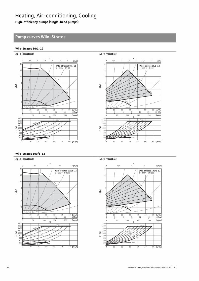
64 Subject to change without prior notice 09/2007 WILO AG
Heating, Air-conditioning, CoolingHigh-efficiency pumps (single-head pumps)
Pump curves Wilo-Stratos
Wilo-Stratos 80/1-12
�p-c (constant)
�p-v (variable)
Wilo-Stratos 100/1-12
�p-c (constant)
�p-v (variable)
v0 1 1,50,5 32 2,5 [m/s]
0
12
14
4
2
8
10
6
H [m
]
[m³/h][l/s]
[lgpm]
P 1 [W
]
0
14001200
8001000
600400200
16001800
200 30 40 50 6010
[m³/h]200 30 40 50 6010
3 6 9 1512 18
50 100 150 2000
0
Q
Wilo-Stratos 80/1-121 ~ 230 V - DN 80
max.
max.
1 m min.2 m
4 m6 m
8 m10 m12 m
min.
p-c
max.
v0 1 1,50,5 32 2,5 [m/s]
0
12
14
4
2
8
10
6
H [m
]
[m³/h][l/s]
[lgpm]
P 1 [W
]
0
14001200
8001000
600400200
16001800
200 30 40 50 6010
[m³/h]200 30 40 50 6010
3 6 9 1512 18
50 100 150 2000
0
Q
Wilo-Stratos 80/1-121 ~ 230 V - DN 80
min.
4 m6 m7 m8 m9 m10 m11 m12 m
5 m
max.
min.
p-v
max.
v0 1 1,50,5 2[m/s]
0
12
14
4
2
8
10
6
H [m
]
[m³/h][l/s]
[lgpm]
P 1 [W
]
0
14001200
8001000
600400200
16001800
200 30 40 50 6010
[m³/h]200 30 40 50 6010
3 6 9 1512 18
50 100 150 2000
0
Q
Wilo-Stratos 100/1-121 ~ 230 V - DN 100
max.
max.
1 m min.2 m
4 m6 m
8 m10 m12 m
min.
p-c
max.
0
12
14
4
2
8
10
6
H [m
]
[m³/h][l/s]
[lgpm]
P 1 [W
]
0
14001200
8001000
600400200
16001800
200 30 40 50 6010
[m³/h]200 30 40 50 6010
3 6 9 1512 18
50 100 150 2000
0
Q
Wilo-Stratos 100/1-121 ~ 230 V - DN 100
min.
4 m6 m7 m8 m9 m10 m11 m12 m
5 m
max.
min.
p-v
max.
v0 1 1,50,5 2[m/s]

65
Heating, Air-conditioning, CoolingHigh-efficiency pumps (single-head pumps)
Terminal diagrams, motor data Wilo-Stratos
Wilo Catalogue A1 - 50 Hz - Circulating Pumps in Glandless Design
Hea
ting,
Air-
cond
ition
ing,
Co
olin
gSe
cond
ary
Hot W
ater
Circ
ulat
ion
Sola
r The
rmal
, Geo
ther
mal
En
ergy
Sys
tem
sSe
rvic
e/Ac
cess
orie
s, S
yste
ms
Switc
hgea
rs a
nd C
ontr
ol
Dev
ices
Pum
p M
anag
emen
t Sys
tem
s
Terminal diagram
*) For additional Stratos IF-Modules, see Chapter “Pump management sys-tems Wilo-Control”
DP: Dual pump management (2 pumps)PLR: Serial digital BA interfaceLON: Serial digital LONWorks interfaceCAN: Serial digital bus interface CANSSM Collective fault signal
(Normally closed contact as per VDI 3814, load capacity 1 A,250 V ~) Function see Chapter “Pump management Wilo-Control,Planning guide”
Motor data
Wilo-Stratos Nominalpower
Speed Power consumption
Current at 1~230
Current at 3~230
Current at 3~400
Motor protection
Threaded cable connection
P2 n P1 I - PG[W] [1/min] [W] [A] - -
25/1-6 65 1400 - 3400 9 - 85 0.13 - 0.78 0.13 - 0.78 – integrated 1 x 7/ 1 x 9/ 1 x 13.525/1-8 100 1400 - 3700 9 - 130 0.13 - 1.20 0.13 - 1.20 – integrated 1 x 7/ 1 x 9/ 1 x 13.530/1-6 65 1400 - 3400 9 - 85 0.13 - 0.78 0.13 - 0.78 – integrated 1 x 7/ 1 x 9/ 1 x 13.530/1-8 100 1400 - 3700 9 - 130 0.13 - 1.20 0.13 - 1.20 – integrated 1 x 7/ 1 x 9/ 1 x 13.530/1-12 200 1600 - 4800 16 - 310 0.16 - 1.37 0.16 - 1.37 – integrated 1 x 7/ 1 x 9/ 1 x 13.532/1-12 200 1600 - 4800 16 - 310 0.16 - 1.37 0.16 - 1.37 – integrated 1 x 7/ 1 x 9/ 1 x 13.540/1-4 100 1600 - 3700 14 - 130 0.16 - 1.20 0.16 - 1.20 – integrated 1 x 7/ 1 x 9/ 1 x 13.540/1-8 200 1800 - 4800 18 - 310 0.17 - 1.37 0.17 - 1.37 – integrated 1 x 7/ 1 x 9/ 1 x 13.540/1-12 350 1400 - 4600 21 - 450 0.16 - 2.01 0.16 - 2.01 – integrated 1 x 7/ 1 x 9/ 1 x 13.550/1-8 200 1800 - 4800 18 - 310 0.17 - 1.37 0.17 - 1.37 – integrated 1 x 7/ 1 x 9/ 1 x 13.550/1-9 350 1400 - 4100 21 - 430 0.16 - 1.88 0.16 - 1.88 – integrated 1 x 7/ 1 x 9/ 1 x 13.550/1-12 500 1400 - 4600 21 - 620 0.16 - 2.70 0.16 - 2.70 – integrated 1 x 7/ 1 x 9/ 1 x 13.565/1-9 500 1400 - 4600 21 - 620 0.16 - 2.70 0.16 - 2.70 – integrated 1 x 7/ 1 x 9/ 1 x 13.565/1-12 650 950 - 3300 38 - 800 0.28 - 3.50 0.28 - 3.50 – integrated 1 x 7/ 1 x 9/ 1 x 13.580/1-12 1300 900 - 3300 40 - 1550 0.30 - 6.80 0.30 - 6.80 – integrated 1 x 7/ 1 x 9/ 1 x 13.5100/1-12 1300 900 - 3300 40 - 1550 0.30 - 6.80 0.30 - 6.80 – integrated 1 x 7/ 1 x 9/ 1 x 13.5
L N PE SSM L1 L3
L2 L3
L1 L2
PE SSM
DP
PLR
DP
LON
Option: IF-modules Stratos *)
PLR-module LON-module
1~230 V, 50/60 Hz
3~230 V, 50/60 Hz
DP
CAN
CAN-module

66 Subject to change without prior notice 09/2007 WILO AG
Heating, Air-conditioning, CoolingHigh-efficiency pumps (single-head pumps)
Dimensions, weights Wilo-Stratos
Dimension drawing A
Permitted installation positions, see Planning guideATTENTION: The cable thread protrudes above the pump flange
with vertical module configuration (Total dimension: dimension b5 + maximum 9 mm)!
Dimension drawing B
Permitted installation positions, see Planning guideATTENTION: The cable thread protrudes above the pump flange
with vertical module configuration (Total dimension: dimension b5 + maximum 9 mm)!
Dimension drawing C Dimension drawing D
l 0
l 2
a2 a1
Pg 7
b3b3
G
b5b4
Pg 9
Pg 13,5
a3
Rpl 1
l 0 l 2
a2 a1
Pg 7
b3b3
b5b4
Pg 9
Pg 13,5
a3
l 1
Ø D
n x Ø d
Ø k
DN
L2Ø k Ø d
L 1
1
n x Ø d 2n x Ø d
Ø D Ø k
DN
Ø d
L
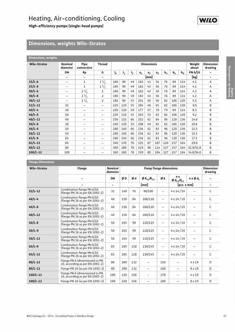
67
Heating, Air-conditioning, CoolingHigh-efficiency pumps (single-head pumps)
Dimensions, weights Wilo-Stratos
Wilo Catalogue A1 - 50 Hz - Circulating Pumps in Glandless Design
Hea
ting,
Air-
cond
ition
ing,
Co
olin
gSe
cond
ary
Hot W
ater
Circ
ulat
ion
Sola
r The
rmal
, Geo
ther
mal
En
ergy
Sys
tem
sSe
rvic
e/Ac
cess
orie
s, S
yste
ms
Switc
hgea
rs a
nd C
ontr
ol
Dev
ices
Pum
p M
anag
emen
t Sys
tem
s
Dimensions, weights
Wilo-Stratos Nominaldiameter
Pipe connection
Thread Dimensions Weight about
Dimensiondrawing
DN Rp G l0 l1 l2 a1 a2 a3 b3 b4 b5 PN 6/10 -- - - [mm] [kg] -
25/1-6 – 1 1 1/2 180 90 49 182 43 56 76 89 114 4.1 A25/1-8 – 1 1 1/2 180 90 49 182 43 56 76 89 114 4.1 A30/1-6 – 1 1/4 2 180 90 49 182 43 56 76 89 114 4.2 A30/1-8 – 1 1/4 2 180 90 49 182 43 56 76 89 114 4.2 A30/1-12 – 1 1/4 2 180 90 55 201 50 56 82 106 120 5.5 A32/1-12 32 – – 220 110 55 204 48 65 82 106 120 9.0 B40/1-4 40 – – 220 110 49 177 57 70 79 89 114 8.3 B40/1-8 40 – – 220 110 55 203 53 63 82 106 120 9.2 B40/1-12 40 – – 250 125 66 252 62 84 96 120 136 14.0 B50/1-8 50 – – 240 120 55 208 49 65 82 106 120 10.6 B50/1-9 50 – – 280 140 66 256 62 83 96 120 136 15.5 B50/1-12 50 – – 280 140 66 256 62 83 96 120 136 15.5 B65/1-9 65 – – 280 140 66 256 62 83 96 120 136 17.5 B65/1-12 65 – – 340 170 78 325 87 107 120 157 164 29.0 B80/1-12 80 – – 360 180 78 329 90 114 127 157 164 31.0/31.0 B100/1-12 100 – – 360 180 78 339 80 104 127 157 164 34.0/34.0 B
Flange dimensions
Wilo-Stratos Flange Nominal diameter
Pump flange dimensions Dimension drawing
- DN Ø D Ø d Ø KL1/KL2 Ø k n xØ dL1/dL2
n x Ø dL -
- - [mm] [pcs. x mm] -
32/1-12 Combination flange PN 6/10(flange PN 16 as per EN 1092-2) 32 140 76 90/100 – 4 x 14 / 19 – C
40/1-4 Combination flange PN 6/10(flange PN 16 as per EN 1092-2) 40 150 84 100/110 – 4 x 14 / 19 – C
40/1-8 Combination flange PN 6/10(flange PN 16 as per EN 1092-2) 40 150 84 100/110 – 4 x 14 / 19 – C
40/1-12 Combination flange PN 6/10(flange PN 16 as per EN 1092-2) 40 150 84 100/110 – 4 x 14 / 19 – C
50/1-8 Combination flange PN 6/10(flange PN 16 as per EN 1092-2) 50 165 99 110/125 – 4 x 14 / 19 – C
50/1-9 Combination flange PN 6/10(flange PN 16 as per EN 1092-2) 50 165 99 110/125 – 4 x 14 / 19 – C
50/1-12 Combination flange PN 6/10(flange PN 16 as per EN 1092-2) 50 165 99 110/125 – 4 x 14 / 19 – C
65/1-9 Combination flange PN 6/10(flange PN 16 as per EN 1092-2) 65 185 118 130/145 – 4 x 14 / 19 – C
65/1-12 Combination flange PN 6/10(flange PN 16 as per EN 1092-2) 65 185 118 130/145 – 4 x 14 / 19 – C
80/1-12 Flange PN 6 (dimensioned to PN 16, according as per EN 1092-2) 80 200 132 – 150 – 4 x 19 D
80/1-12 Flange PN 16 (as per EN 1092-2) 80 200 132 – 160 – 8 x 19 D
100/1-12 Flange PN 6 (dimensioned to PN 16, according as per EN 1092-2) 100 220 156 – 170 – 4 x 19 D
100/1-12 Flange PN 16 (as per EN 1092-2) 100 220 156 – 180 – 8 x 19 D

68 Subject to change without prior notice 09/2007 WILO AG
Heating, Air-conditioning, CoolingHigh-efficiency pumps (twin-head pumps)
Equipment/function Wilo-Stratos-D
Wilo-Stratos-D
Operating modes
Speed-stage switching –
Manual control mode (n=constant) •�p-c for constant differential pressure •�p-v for variable differential pressure •
�p-T for temperature-prompted differential pressure •(programmable via IR-Module, IR-Monitor, LON or CAN)
Manual functions
Setting the operating mode •Setting the differential-pressure setpoint •Setting to “Autopilot” (automatic setback operation) •Setting the pump to ON/OFF •Setting the speed (manual setting mode) •Setting the speed stages –
Automatic functions
Stageless power adjustment depending on the oper-ating mode •
“Autopilot” automatic setback operation •Deblocking function •Soft start •Safety control –
Full motor protection with integrated trip electronics •
External control functions
Control input “Overriding Off” •Possible with Stratos IF-Modules (accessory)
Control input “Overriding Min” •Possible with Stratos IF-Modules (accessory)
Control input “Analogue In 0 - 10 V” (remote speed adjustment)
•Possible with Stratos IF-Modules (accessory)
Control input “Analogue In 0 - 10 V” (remote setpoint adjustment)
•Possible with Stratos IF-Modules (accessory)
Signal and display functions
Individual/collective fault signal (potential-free NC contact)
•(programmable with IR-Monitor)
Collective fault signal (potential-free NC contact) •
Individual run signal (potential-free NO contact) •Possible with Stratos IF-Modules (accessory)
Thermal winding contact(WSK, potential-free NC contact) –
Fault signal light •
• = available, – = not available
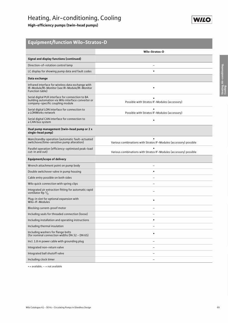
69
Heating, Air-conditioning, CoolingHigh-efficiency pumps (twin-head pumps)
Equipment/function Wilo-Stratos-D
Wilo Catalogue A1 - 50 Hz - Circulating Pumps in Glandless Design
Hea
ting,
Air-
cond
ition
ing,
Co
olin
gSe
cond
ary
Hot W
ater
Circ
ulat
ion
Sola
r The
rmal
, Geo
ther
mal
En
ergy
Sys
tem
sSe
rvic
e/Ac
cess
orie
s, S
yste
ms
Switc
hgea
rs a
nd C
ontr
ol
Dev
ices
Pum
p M
anag
emen
t Sys
tem
s
Signal and display functions (continued)
Direction-of-rotation control lamp –
LC display for showing pump data and fault codes •
Data exchange
Infrared interface for wireless data exchange with IR-Module/IR-Monitor (see IR-Module/IR-Monitor Function table)
•
Serial digital PLR interface for connection to BA building automation via Wilo interface converter or company-specific coupling module
•Possible with Stratos IF-Modules (accessory)
Serial digital LON interface for connection to a LONWorks network
•Possible with Stratos IF-Modules (accessory)
Serial digital CAN interface for connection to a CAN bus system •
Dual pump management (twin-head pump or 2 x single-head pump)
Main/standby operation (automatic fault-actuated switchover/time-sensitive pump alteration)
•Various combinations with Stratos IF-Modules (accessory) possible
Parallel operation (efficiency-optimised peak-load cut-in and out)
•Various combinations with Stratos IF-Modules (accessory) possible
Equipment/scope of delivery
Wrench attachment point on pump body –
Double switchover valve in pump housing •Cable entry possible on both sides –
Wilo quick connection with spring clips –
Integrated air extraction fitting for automatic rapid ventilator Rp 3/8
–
Plug-in slot for optional expansion with Wilo-IF-Modules •
Blocking current-proof motor –
Including seals for threaded connection (loose) –
Including installation and operating instructions •Including thermal insulation –
Including washers for flange bolts(for nominal connection widths DN 32 - DN 65) •
Incl. 1.8 m power cable with grounding plug –
Integrated non-return valve –
Integrated ball shutoff valve –
Including clock timer –
Wilo-Stratos-D
• = available, – = not available
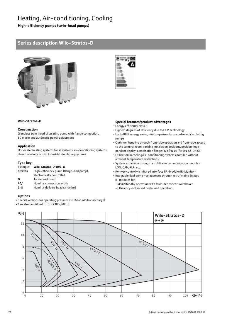
70 Subject to change without prior notice 09/2007 WILO AG
Heating, Air-conditioning, CoolingHigh-efficiency pumps (twin-head pumps)
Series description Wilo-Stratos-D
Wilo-Stratos-D
ConstructionGlandless twin-head circulating pump with flange connection, EC motor and automatic power adjustment
ApplicationHot-water heating systems for all systems, air-conditioning systems, closed cooling circuits, industrial circulating systems
Type keyExample: Wilo-Stratos-D 40/1-8Stratos High-efficiency pump (flange-end pump),
electronically controlledD Twin-head pump40/ Nominal connection width1-8 Nominal delivery head range [m]
Options• Special versions for operating pressure PN 16 (at additional charge)• Can also be utilised for 1 x 230 V/60 Hz
Special features/product advantages• Energy efficiency class A• Highest degrees of efficiency due to ECM technology• Up to 80% energy savings in comparison to uncontrolled circulating
pumps• Optimum handling through front-side operation and front-side access
to the terminal room, variable installation positions, position-inde-pendent display, combination flange PN 6/PN 10 (for DN 32-DN 65)
• Utilisation in cooling/air-conditioning systems possible without ambient temperature restrictions
• System expansion through retrofittable communication modules LON, CAN, PLR, etc.
• Remote control via infrared interface (IR-Module/ IR-Monitor)• Integrable dual pump management through retrofittable Stratos
IF-modules for:- Main/standby operation with fault-dependent switchover- Efficiency-optimised peak-load operation
32/1-8
32/1-12 40/1-12
50/1-9
50/1-12 65/1-12
80/1-12
40(50)/1-8
+Wilo-Stratos-D
00
2
4
6
8
10
12
H[m]
10 20 30 40 50 60 70 80 90 100 Q[m³/h]

71
Heating, Air-conditioning, CoolingHigh-efficiency pumps (twin-head pumps)
Series description Wilo-Stratos-D
Wilo Catalogue A1 - 50 Hz - Circulating Pumps in Glandless Design
Hea
ting,
Air-
cond
ition
ing,
Co
olin
gSe
cond
ary
Hot W
ater
Circ
ulat
ion
Sola
r The
rmal
, Geo
ther
mal
En
ergy
Sys
tem
sSe
rvic
e/Ac
cess
orie
s, S
yste
ms
Switc
hgea
rs a
nd C
ontr
ol
Dev
ices
Pum
p M
anag
emen
t Sys
tem
s
Equipment/function
Operating modes• Manual control mode (n=constant)• �p-c for constant differential pressure• �p-v for variable differential pressure• �p-T for temperature-controlled differential pressure
(programmable via IR-Module, IR-Monitor, LON or CAN)
Manual functions• Setting the operating mode• Setting the differential-pressure setpoint• Setting to “Autopilot” (automatic setback operation)• Setting the pump to ON/OFF• Setting the speed (manual setting mode)
Automatic functions• Stageless power adjustment depending on the operating mode• “Autopilot” automatic setback operation• Deblocking function• Soft start• Full motor protection with integrated trip electronics
External control functions• Control input “Overriding Off” (possible with Stratos IF-Modules)• Control input “Overriding Min” (possible with Stratos IF-Modules)• Control input “Analogue In 0 - 10 V” (remote speed adjustment)
(possible with Stratos IF-Modules)• Control input “Analogue In 0 - 10 V” (remote setpoint adjustment)
(possible with Stratos IF-Modules)
Signal and display functions• Individual / collective fault signal (potential-free NC contact)
(programmable with the IR-Monitor)• Collective fault signal (potential-free NC contact)• Individual run signal (potential-free NO contact)
(possible with Stratos IF-Modules)• Fault signal light• LC display for showing pump data and fault codes
Data exchange• Infrared interface for wireless data exchange with IR-Module/IR-Monitor
(see IR-Module/IR-Monitor Function table)• Serial digital PLR interface for connection to BA via Wilo interface
converter or company-specific coupling module (possible with Stratos IF-Modules)
• Serial digital LON interface for connection to a LONWorks network (possible with Stratos IF-Modules)
• Serial digital CAN interface for connection to a CAN bus system CAN (possible with Stratos IF-Modules)
Dual pump management (twin-head pump or 2 x single-head pump)
• Main/standby operation (automatic fault-actuated switchover/time-sensitive pump alteration): Various combinations with Stratos IF-modules (accessory) possible
• Parallel operation (efficiency-optimised peak-load cut-in and out): Various combinations with Stratos IF-Modules (accessory) possible
Equipment/scope of delivery• Double switchover valve in pump housing• Plug-in slot for optional expansion with Wilo-IF-Modules• Including installation and operating instructions• Including washers for flange bolts (for nominal connection widths
DN 32 - DN 65)
Accessories• IR-Module• IR-Monitor• IF-Modules Stratos:
PLR, LON, CAN, Ext. Off, Ext. Min., SBM, Ext.Aus/SBM• Analogue interface converter AnaCon• Digital interface converter DigiCon/DigiCon-A

72 Subject to change without prior notice 09/2007 WILO AG
Heating, Air-conditioning, CoolingHigh-efficiency pumps (twin-head pumps)
Technical data Wilo-Stratos-Ds
Wilo-Stratos-D
32/1-8 32/1-12 40/1-8 40/1-12 50/1-8 50/1-9 50/1-12 65/1-12 80/1-12
Approved fluids (other fluids/media on request)
Heating water (as per VDI 2035) • • • • • • • • •Water/glycol mixtures (maximum 1:1; mixtures with more than 20 % glycol content require rechecking of the pumping data)
• • • • • • • • •
Secondary hot water and water for food businesses as per TrinkwV 2001 – – – – – – – – –
Performance
Maximum delivery head [m] 7 9 8 12 8 9 11 11 13
Maximum flow volume [m3/h] 13 19 21 32 21 38 43 72 107
Permitted field of application
Temperature range for utilisation in heating, ventila-tion & air conditioning systems
at maximum ambient temperature +25 °C [°C]at maximum ambient temperature +40 °C [°C]
–- 10 to + 110
Temperature range for utilisation in secondary hot water circulation systems
at maximum ambient temperature +40 °C [°C]at maximum ambient temperature +40 °C in short-term operation 2 h [°C]
–
–
–
–
–
–
–
–
–
–
–
–
–
–
–
–
–
–
Maximum permissible total hardness in secondary hot water-circulation systems [°d] – – – – – – – – –
Standard version with nominal pressure, pmax [bar] 6/10 6/10 6/10 6/10 6/10 6/10 6/10 6/10 6
Special version with nominal pressure, pmax [bar] 16 16 16 16 16 16 16 16 10, 16
Pipe connections
Screwed connection Rp – – – – – – – – –
Nominal connection diameter flange DN 32 32 40 40 50 50 50 65 80
Flange for counter flange PN 6, standard version – – – – – – – – •Flange for counter flange PN 16, special version • • • • • • • • •Combination flange PN 6/10 for counter flange PN 6 and PN 16, standard version • • • • • • • • –
Support-bracket mounting (with horizontal shaft only), standard version – – – – – – – – –
Support-bracket mounting (with horizontal shaft only), special version – – – – – – – – –
Electrical connection
Mains connection 1~ [V], standard version 230 230 230 230 230 230 230 230 230
Mains connection 3~ [V], standard version 230 230 230 230 230 230 230 230 230
Mains connection 3~ [V], with optional switching plug – – – – – – – – –
Mains frequency [Hz] 50/60 50/60 50/60 50/60 50/60 50/60 50/60 50/60 50/60
• = available, – = not available

73
Heating, Air-conditioning, CoolingHigh-efficiency pumps (twin-head pumps)
Technical data Wilo-Stratos-D
Wilo Catalogue A1 - 50 Hz - Circulating Pumps in Glandless Design
Hea
ting,
Air-
cond
ition
ing,
Co
olin
gSe
cond
ary
Hot W
ater
Circ
ulat
ion
Sola
r The
rmal
, Geo
ther
mal
En
ergy
Sys
tem
sSe
rvic
e/Ac
cess
orie
s, S
yste
ms
Switc
hgea
rs a
nd C
ontr
ol
Dev
ices
Pum
p M
anag
emen
t Sys
tem
s
Motor/electronics
Electromagnetic compatibility EN 61800-3
Emitted interference EN 61000-6-3
Immunity to interference EN 61000-6-2
Power electronics Frequency converter
Protection class IP 44 IP 44 IP 44 IP 44 IP 44 IP 44 IP 44 IP 44 IP 44
Insulation class F F F F F F F F F
Materials
Pump housing Cast iron (EN-GJL-250)
Impeller Plastic (PPS - 40 % GF) Plastic (PP - 50% GF)
Shaft Stainless steel (X46Cr13)
Bearing Metal-impregnated carbon
Minimum suction head at suction port [m]for the prevention of cavitation at water delivery temperature
50 °C 3 3 3 5 3 5 5 7 7
95 °C 10 10 10 12 10 12 12 15 15
110 °C 16 16 16 18 16 18 18 23 23
Wilo-Stratos-D
32/1-8 32/1-12 40/1-8 40/1-12 50/1-8 50/1-9 50/1-12 65/1-12 80/1-12
• = available, – = not available

74 Subject to change without prior notice 09/2007 WILO AG
Heating, Air-conditioning, CoolingHigh-efficiency pumps (twin-head pumps)
Pump curves Wilo-Stratos-D
Wilo-Stratos-D 32/1-8
�p-c (constant)
�p-v (variable)
Wilo-Stratos-D 32/1-12
�p-c (constant)
�p-v (variable)
Q
max.
max.
min.
min.
v0 0,5 1 1,5 2 2,5 3 3,5 4 [m/s]
0
2
1
3
4
6
5
7
8
H [m
]
[m³/h][l/s]
[lgpm]
1280 4 10621 1,5 2 2,5 3,530,50
10 20 30 400
Wilo-Stratos-D 32/1-81 ~ 230 V - DN 32
+
P1 Wilo-Stratos 32/1-8
6 m 5 m 4 m
3 m
2 m
1 m
7 m
max.
p-c
P 1 [W
]
0
150
100
50
200
250
300
1280 4 1062 [m³/h]
0
4
5
7
6
8
2
1
3
H [m
]
Q
P 1 [W
]
[m3/h][l/s]
[lgpm]
12106 840 2
[m3/h]12106 840 2
2
10
32,5 3,5
3020
1,510,5
0
0
40
0
150
100
50
200
250
300
[m/s]v
210 2,51,50,5 43 3,5
max.
3 m4 m5 m
6 m7 m
min.
min.
max.
p-v
P1 Wilo-Stratos 32/1-8
Wilo-Stratos-D 32/1-81 ~ 230 V - DN 32
+
v0 1 2 3 4 5 6 [m/s]
0
8
10
12
4
2
6
H [m
]
[m³/h][l/s]
[lgpm]
P 1 [W
]
0
300
200
100
400
500
600
700
12 16 1880 4 10 1462
12 16 1880 4 10 1462 [m³/h]
2 3 4 5
10 20 30 40 50 60
1
0
0
P1 Wilo-Stratos 32/1-12
Wilo-Stratos-D 32/1-121 ~ 230 V - DN 32
+
max.
1 m
9 m 8 m 7 m 6 m 5 m 4 m
2 m
3 m
min.
max.
p-c
max.
min.
Q
v0 1 2 3 4 5 6 [m/s]
0
8
10
12
4
2
6
H [m
]
[m³/h][l/s]
[lgpm]
P 1 [W
]
0
300
200
100
400
500
600
700
12 16 1880 4 10 1462
12 16 1880 4 10 1462 [m³/h]
2 3 4 5
10 20 30 40 50 60
1
0
0
Wilo-Stratos-D 32/1-121 ~ 230 V - DN 32
+
Q
P1 Wilo-Stratos 32/1-12
max.
min.
8 m 7 m 6 m 5 m 4 m
p-v
max.
min.
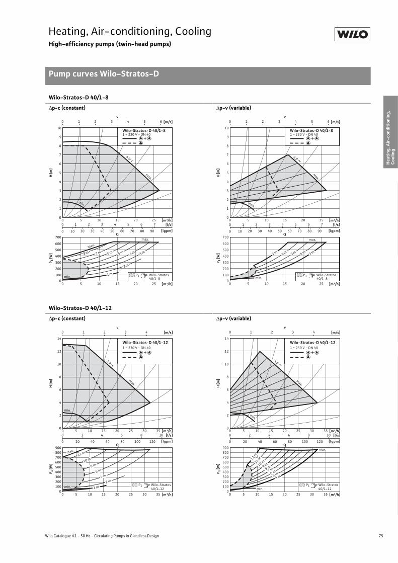
75
Heating, Air-conditioning, CoolingHigh-efficiency pumps (twin-head pumps)
Pump curves Wilo-Stratos-D
Wilo Catalogue A1 - 50 Hz - Circulating Pumps in Glandless Design
Hea
ting,
Air-
cond
ition
ing,
Co
olin
gSe
cond
ary
Hot W
ater
Circ
ulat
ion
Sola
r The
rmal
, Geo
ther
mal
En
ergy
Sys
tem
sSe
rvic
e/Ac
cess
orie
s, S
yste
ms
Switc
hgea
rs a
nd C
ontr
ol
Dev
ices
Pum
p M
anag
emen
t Sys
tem
s
Wilo-Stratos-D 40/1-8
�p-c (constant)
�p-v (variable)
Wilo-Stratos-D 40/1-12
�p-c (constant)
�p-v (variable)
v0 1 2 3 4 5 6 [m/s]
0
8
10
4
2
6
7
9
3
1
5
H [m
]
[m³/h][l/s]
[lgpm]
P 1 [W
]
0
300
200
100
400
500
600
700
200 10 251552 3 4 5 6 7
10 20 30 40 50 60 70 80 90
1
0
0
[m³/h]200 10 25155
Wilo-Stratos-D 40/1-81 ~ 230 V - DN 40
+
Q
P1 Wilo-Stratos 40/1-8
max.
min.
max.
3 m
2 m
1 m
4 m5 m6 m7 m8 m
p-c
max.
min.
v0 1 2 3 4 5 6 [m/s]
0
8
10
4
2
6
7
9
3
1
5
H [m
][m³/h]
[l/s]
[lgpm]
P 1 [W
]
0
300
200
100
400
500
600
700
200 10 251552 3 4 5 6 7
10 20 30 40 50 60 70 80 90
1
0
0
[m³/h]200 10 25155
Wilo-Stratos-D 40/1-81 ~ 230 V - DN 40
+
Q
P1 Wilo-Stratos 40/1-8min.
3 m4 m5 m6 m7 m
max.
p-v
max.
min.
v0 1 2 3 4 [m/s]
0
8
10
14
12
4
2
6
H [m
]
[m³/h][l/s]
[lgpm]
P 1 [W
]
0
300200100
400500600
900800700
15 25 35300 10 2054 6 8 10
20 40 60 80 100 120
2
0
0
[m³/h]15 25 35300 10 205
P1 Wilo-Stratos 40/1-12
Wilo-Stratos-D 40/1-121 ~ 230 V - DN 40
+
Q
min. 1 m2 m
4 m6 m
8 m
12 m
10 m
max.
p-c
max.
min.
v0 1 2 3 4
0
8
10
14
12
4
2
6
H [m
]P 1
[W]
0
300200100
400500600
900800700
15 25 35300 10 2054 6 8 10
20 40 60 80 100 120
2
0
0
15 25 35300 10 205
P1 Wilo-Stratos 40/1-12
Wilo-Stratos-D 40/1-121 ~ 230 V - DN 40
+
Q
[m/s]
[m³/h][l/s]
[lgpm]
[m³/h]
max.
min.
5 m6 m
4 m
7 m8 m9 m10 m11 m12 m
p-v
max.
min.

76 Subject to change without prior notice 09/2007 WILO AG
Heating, Air-conditioning, CoolingHigh-efficiency pumps (twin-head pumps)
Pump curves Wilo-Stratos-D
Wilo-Stratos-D 50/1-8
�p-c (constant)
�p-v (variable)
Wilo-Stratos-D 50/1-9
�p-c (constant)
�p-v (variable)
v0 1 2 3 [m/s]
0
7
8
10
9
5
4
3
2
1
6
H [m
]P 1
[W]
[m³/h][l/s]
[lgpm]
0
500
400
200
300
100
600
700
100 15 20 255
[m³/h]100 15 20 255
2 3 4 65 7
10 20 30 40 50 70 60 80 90
1
0
0
P1 Wilo-Stratos 50/1-8
Q
Wilo-Stratos-D 50/1-81 ~ 230 V - DN 50
+
max.
min.
max.
3 m
2 m
1 m
4 m5 m6 m7 m8 m
p-c
max.
min.
v0 1 2 3 [m/s]
0
7
8
10
9
5
4
3
2
1
6
H [m
]P 1
[W]
[m³/h][l/s]
[lgpm]
0
500
400
200
300
100
600
700
100 15 20 255
[m³/h]100 15 20 255
2 3 4 65 7
10 20 30 40 50 70 60 80 90
1
0
0
P1 Wilo-Stratos 50/1-8
Q
Wilo-Stratos-D 50/1-81 ~ 230 V - DN 50
+
min.
3 m4 m5 m6 m7 m
max.
p-v
max.
min.
v0 1 2 3 4 [m/s]
0
8
10
12
4
2
6
H [m
]
[m³/h][l/s]
[lgpm]
P 1 [W
]
0
300200100
400500600
900800700
15 25 35300 10 2054 6 8 10
20 40 60 80 100 120
2
0
0
[m³/h]15 25 35300 10 205
P1 Wilo-Stratos 50/1-9
Wilo-Stratos-D 50/1-91 ~ 230 V - DN 50
+
Q
2 m1 m
4 m
6 m
8 m
min.
max.
p-c
max.
min.
v0 1 2 3 4 [m/s]
0
8
10
12
4
2
6
H [m
]
[m³/h][l/s]
[lgpm]
P 1 [W
]
0
300200100
400500600
900800700
15 25 35300 10 2054 6 8 10
20 40 60 80 100 120
2
0
0
[m³/h]15 25 35300 10 205
P1 Wilo-Stratos 50/1-9
Wilo-Stratos-D 50/1-91 ~ 230 V - DN 50
+
Qmax.
min.
3 m4 m
5 m6 m
7 m8 m
p-v
max.
min.
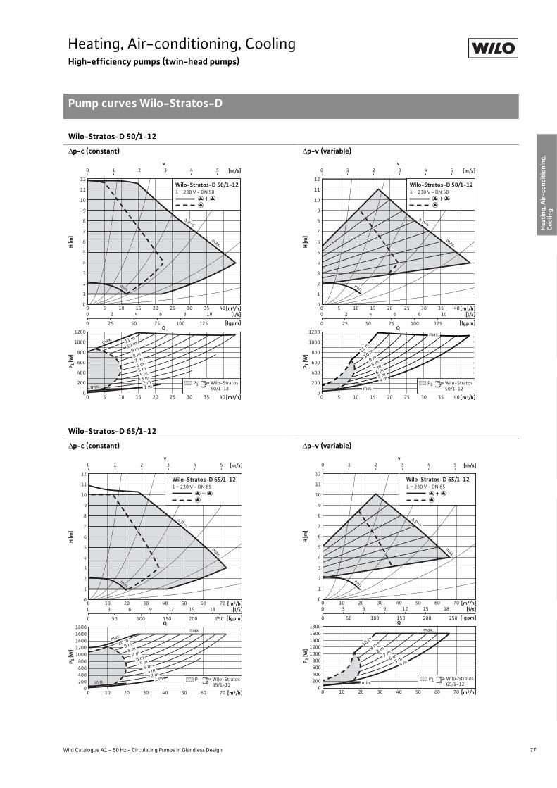
77
Heating, Air-conditioning, CoolingHigh-efficiency pumps (twin-head pumps)
Pump curves Wilo-Stratos-D
Wilo Catalogue A1 - 50 Hz - Circulating Pumps in Glandless Design
Hea
ting,
Air-
cond
ition
ing,
Co
olin
gSe
cond
ary
Hot W
ater
Circ
ulat
ion
Sola
r The
rmal
, Geo
ther
mal
En
ergy
Sys
tem
sSe
rvic
e/Ac
cess
orie
s, S
yste
ms
Switc
hgea
rs a
nd C
ontr
ol
Dev
ices
Pum
p M
anag
emen
t Sys
tem
s
Wilo-Stratos-D 50/1-12
�p-c (constant)
�p-v (variable)
Wilo-Stratos-D 65/1-12
�p-c (constant)
�p-v (variable)
v0 1 2 3 4 5 [m/s]
0
7
8
12
11
10
9
5
4
3
2
1
6
H [m
]P 1
[W]
[m³/h][l/s]
[lgpm]
0
800
600
200
400
1000
1200
100 15 20 25 30 35 4052 4 86 10
25 50 75 100 1250
0
[m³/h]100 15 20 25 30 35 405
P1 Wilo-Stratos 50/1-12
Q
Wilo-Stratos-D 50/1-121 ~ 230 V - DN 50
+
max.
min. 1 m2 m
3 m4 m
5 m6 m
7 m8 m
9 m10 m11 m
p-c
max.
min.
v0 1 2 3 4 5 [m/s]
0
7
8
12
11
10
9
5
4
3
2
1
6
H [m
]P 1
[W]
[m³/h][l/s]
[lgpm]
0
800
600
200
400
1000
1200
100 15 20 25 30 35 4052 4 86 10
25 50 75 100 1250
0
[m³/h]100 15 20 25 30 35 405
P1 Wilo-Stratos 50/1-12
Q
Wilo-Stratos-D 50/1-121 ~ 230 V - DN 50
+
min.
max.
4 m5 m6 m7 m8 m
9 m10 m11 m
p-v
max.
min.
v0 1 2 3 4 5 [m/s]
0
7
8
12
11
10
9
5
4
3
2
1
6
H [m
]P 1
[W]
[m³/h][l/s]
[lgpm]
0
800600
200400
10001200140016001800
200 30 40 50 60 70103 6 9 1512 18
50 100 150 200 2500
0
[m³/h]200 30 40 50 60 7010
P1 Wilo-Stratos 65/1-12
Q
Wilo-Stratos-D 65/1-121 ~ 230 V - DN 65
+
max.
max.
2 m3 m
4 m5 m
6 m
1 m
7 m8 m
9 m10 m
min.
p-c
max.
min.
v0 1 2 3 4 5 [m/s]
0
7
8
12
11
10
9
5
4
3
2
1
6
H [m
]P 1
[W]
[m³/h][l/s]
[lgpm]
0
800600
200400
10001200140016001800
200 30 40 50 60 70103 6 9 1512 18
50 100 150 200 2500
0
[m³/h]200 30 40 50 60 7010
P1 Wilo-Stratos 65/1-12
Q
Wilo-Stratos-D 65/1-121 ~ 230 V - DN 65
+
max.
4 m5 m6 m7 m8 m9 m10 m
min.
p-v
max.
min.
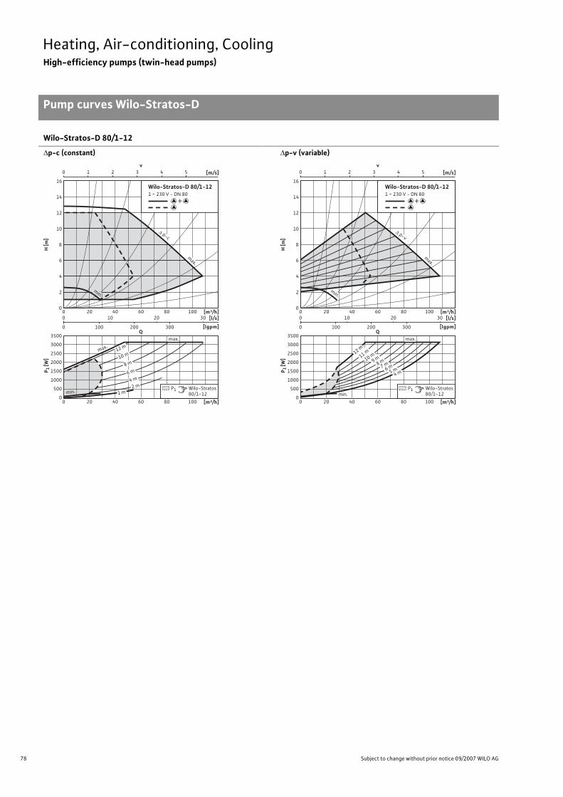
78 Subject to change without prior notice 09/2007 WILO AG
Heating, Air-conditioning, CoolingHigh-efficiency pumps (twin-head pumps)
Pump curves Wilo-Stratos-D
Wilo-Stratos-D 80/1-12
�p-c (constant)
�p-v (variable)
v0 1 2 3 4 5 [m/s]
0
8
14
12
10
4
2
6
H [m
]P 1
[W]
[m³/h][l/s]
[lgpm]
0
1000
500
1500
2000
2500
3000
3500
400 60 80 1002010 20 30
100 200 3000
0
[m³/h]400 60 80 10020
P1 Wilo-Stratos 80/1-12
Q
Wilo-Stratos-D 80/1-121 ~ 230 V - DN 80
+
16
min.
max.
max.
2 m4 m
6 m
1 m
8 m10 m
12 m
p-c
max.
min.
v0 1 2 3 4 5 [m/s]
0
8
14
12
10
4
2
6
H [m
]P 1
[W]
[m³/h][l/s]
[lgpm]
0
1000
500
1500
2000
2500
3000
3500
400 60 80 1002010 20 30
100 200 3000
0
[m³/h]400 60 80 10020
P1 Wilo-Stratos 80/1-12
Q
Wilo-Stratos-D 80/1-121 ~ 230 V - DN 80
+
16
max.
min.
4 m5 m6 m7 m8 m9 m10 m11 m12 m
p-v
max.
min.

79
Heating, Air-conditioning, CoolingHigh-efficiency pumps (twin-head pumps)
Terminal diagrams, motor data Wilo-Stratos-D
Wilo Catalogue A1 - 50 Hz - Circulating Pumps in Glandless Design
Hea
ting,
Air-
cond
ition
ing,
Co
olin
gSe
cond
ary
Hot W
ater
Circ
ulat
ion
Sola
r The
rmal
, Geo
ther
mal
En
ergy
Sys
tem
sSe
rvic
e/Ac
cess
orie
s, S
yste
ms
Switc
hgea
rs a
nd C
ontr
ol
Dev
ices
Pum
p M
anag
emen
t Sys
tem
s
Terminal diagram
*) For additional Stratos IF-Modules, see Chapter “ Pump management sys-tems” Wilo-Control”
DP: Dual pump management (2 pumps)PLR: Serial digital BA interfaceLON: Serial digital LONWorks interfaceCAN: Serial digital bus interface CANSSM Collective fault signal
(Normally closed contact as per VDI 3814, load capacity 1 A, 250 V ~) Function see Chapter “Pump management Wilo-Control, Planning guide”
Motor data
Wilo-Stratos D... Nominalpower
Speed Power consumption
Current for 1~230 V
Current for 3~230 V
Current for 3~400 V
Motor protection
Cable screwed connection
P2 n P1 I - PG[W] [1/min] [W] [A] - -
32/1-8 100 1400 - 3700 9 - 130 0.13 - 1.20 0.17 - 1.37 – integrated 1 x 7/1 x 9 /1 x 13.5
32/1-12 200 1600 - 4800 16 - 310 0.16 - 1.37 0.16 - 1.37 – integrated 1 x 7/1 x 9 /1 x 13.5
40/1-8 200 1800 - 4800 18 - 310 0.17 - 1.37 0.17 - 1.37 – integrated 1 x 7/1 x 9 /1 x 13.5
40/1-12 350 1400 - 4600 21 - 450 0.16 - 2.01 0.16 - 2.01 – integrated 1 x 7/1 x 9 /1 x 13.5
50/1-8 200 1800 - 4800 18 - 310 0.17 - 1.37 0.17 - 1.37 – integrated 1 x 7/1 x 9 /1 x 13.5
50/1-9 350 1400 - 4100 21 - 430 0.16 - 1.88 0.16 - 1.88 – integrated 1 x 7/1 x 9 /1 x 13.5
50/1-12 500 1400 - 4600 21 - 620 0.16 - 2.70 0.16 - 2.70 – integrated 1 x 7/1 x 9 /1 x 13.5
65/1-12 650 950 - 3300 38 - 800 0.28 - 3.50 0.28 - 3.50 – integrated 1 x 7/1 x 9 /1 x 13.5
80/1-12 1300 900 - 3300 40 - 1550 0.30 - 6.80 0.30 - 6.80 – integrated 1 x 7/1 x 9 /1 x 13.5
L N PE SSM L1 L3
L2 L3
L1 L2
PE SSM
DP
PLR
DP
LON
Option: IF-modules Stratos *)
PLR-module LON-module
1~230 V, 50/60 Hz
3~230 V, 50/60 Hz
DP
CAN
CAN-module

80 Subject to change without prior notice 09/2007 WILO AG
Heating, Air-conditioning, CoolingHigh-efficiency pumps (twin-head pumps)
Dimensions, weights Wilo-Stratos-D
Dimension drawing A
Permitted installation positions, see Planning guideATTENTION: The cable connection protrudes above the pump flange
(total dimension: dimension l3 + maximum 9 mm)!
Dimension drawing B Dimension drawing C
Dimensions, weights
Wilo-Stratos D... Nominal diameter
Dimensions Weight about
Dimension drawing
DN l0 l1 l3 l4 a1 a2 b1 b2 b4 b5 PN 6/10 -- [mm] [kg] -
32/1-8 32 220 110 114 89 182 44 112 106 107 107 12.0 A 32/1-12 32 220 110 120 106 204 57 117 130 110 130 16.5 A 40/1-8 40 220 110 120 106 200 64 125 138 115 135 16.6 A 40/1-12 40 250 125 136 120 252 62 151 144 145 145 25.0 A 50/1-8 50 240 120 120 106 204 61 123 135 113 132 18.0 A 50/1-9 50 280 140 136 120 256 62 159 148 145 145 27.0 A 50/1-12 50 280 140 136 120 256 62 159 148 145 145 27.0 A 65/1-12 65 340 170 164 156 325 88 209 196 188 188 52.8 A 80/1-12 80 360 180 164 156 329 100 235 221 203 203 61.0/61.0 A
Pg 7
Pg 9Pg 13,5
a1b 2
b 1b5b4
l 0l 3
l 4
a2
l 1
Ø D
n x Ø d
Ø k
DN
L2Ø k Ø d
L 1
1
n x Ø d 2n x Ø d
Ø D Ø k
DN
Ø d
L

81
Heating, Air-conditioning, CoolingHigh-efficiency pumps (twin-head pumps)
Dimensions, weights Wilo-Stratos-D
Wilo Catalogue A1 - 50 Hz - Circulating Pumps in Glandless Design
Hea
ting,
Air-
cond
ition
ing,
Co
olin
gSe
cond
ary
Hot W
ater
Circ
ulat
ion
Sola
r The
rmal
, Geo
ther
mal
En
ergy
Sys
tem
sSe
rvic
e/Ac
cess
orie
s, S
yste
ms
Switc
hgea
rs a
nd C
ontr
ol
Dev
ices
Pum
p M
anag
emen
t Sys
tem
s
Flange dimensions
Wilo-Stratos-D... Flange Nominal diameter
Pump flange dimensions Dimension drawing
- DN Ø D Ø d Ø KL1/KL2 Ø k n xØ dL1/dL2
n x Ø dL -
- - [mm] [pcs. x mm] -
32/1-8 Combination flange PN 6/10(flange PN 16 as per EN 1092-2) 32 140 76 90/100 – 4 x 14 / 19 – B
32/1-12 Combination flange PN 6/10(flange PN 16 as per EN 1092-2) 32 140 76 90/100 – 4 x 14 / 19 – B
40/1-8 Combination flange PN 6/10(flange PN 16 as per EN 1092-2) 40 150 84 100/110 – 4 x 14 / 19 – B
40/1-12 Combination flange PN 6/10(flange PN 16 as per EN 1092-2) 40 150 84 100/110 – 4 x 14 / 19 – B
50/1-8 Combination flange PN 6/10(flange PN 16 as per EN 1092-2) 50 165 99 110/125 – 4 x 14 / 19 – B
50/1-9 Combination flange PN 6/10(flange PN 16 as per EN 1092-2) 50 165 99 110/125 – 4 x 14 / 19 – B
50/1-12 Combination flange PN 6/10(flange PN 16 as per EN 1092-2) 50 165 99 110/125 – 4 x 14 / 19 – B
65/1-12 Combination flange PN 6/10(flange PN 16 as per EN 1092-2) 65 185 118 130/145 – 4 x 14 / 19 – B
80/1-12 Flange PN 6 (dimensioned to PN 16, according as per EN 1092-2) 80 200 132 – 150 – 4 x 19 C
80/1-12 Flange PN 16(as per EN 1092-2) 80 200 132 – 160 – 8 x 19 C
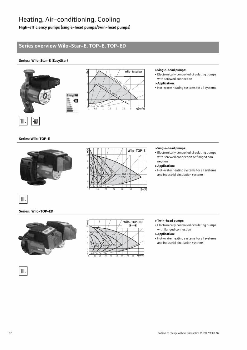
82 Subject to change without prior notice 09/2007 WILO AG
Heating, Air-conditioning, CoolingHigh-efficiency pumps (single-head pumps/twin-head pumps)
Series overview Wilo-Star-E, TOP-E, TOP-ED
Series: Wilo-Star-E (EasyStar)
> Single-head pumps:• Electronically controlled circulating pumps
with screwed connection> Application:• Hot-water heating systems for all systems
Series: Wilo-TOP-E
> Single-head pumps:• Electronically controlled circulating pumps
with screwed connection or flanged con-nection
> Application:• Hot-water heating systems for all systems
and industrial circulation systems
Series: Wilo-TOP-ED
> Twin-head pumps:• Electronically controlled circulating pumps
with flanged connection> Application:• Hot-water heating systems for all systems
and industrial circulation systems
Q[m³/h]
Wilo-EasyStar
H[m
]
00 0,5 1 1,5 2 32,5
1
2
3
4Star-E 15 (25, 30)/1-5
Star-E 15 (25, 30)/1-3
0 10 20 30 40 50 0 1
2
4
6
8
10
Wilo-TOP-E
80/1-10100/1-10
40/1-4
50/1-7
30/1-10 40/1-10
50/1-10
50/1-6
65/1-10
25
(30
)/1-7
Q[m3/h]
H[m
]
0 10 20 30 40 50 60 70 80 0 1
2
4
6
8
10
32/1-7
40/1-750/1-6
80/1-10
65/1-10
40/1-10 50/1-10
50/1-7
Wilo-TOP-ED
Q[m3/h]
H[m
]
+

83
Heating, Air-conditioning, CoolingHigh-efficiency pumps (single-head pumps/twin-head pumps)
Series overview Wilo-Star-E, TOP-E, TOP-ED
Wilo Catalogue A1 - 50 Hz - Circulating Pumps in Glandless Design
Hea
ting,
Air-
cond
ition
ing,
Co
olin
gSe
cond
ary
Hot W
ater
Circ
ulat
ion
Sola
r The
rmal
, Geo
ther
mal
En
ergy
Sys
tem
sSe
rvic
e/Ac
cess
orie
s, S
yste
ms
Switc
hgea
rs a
nd C
ontr
ol
Dev
ices
Pum
p M
anag
emen
t Sys
tem
s
Series: Wilo-Star-E (EasyStar)
> Product advantages:• Energy-saving pump especially for single- and two-family houses, as well as for two to six-
family houses.• Up to 50% energy savings in comparison to uncontrolled heating pumps• Optimum heating comfort with maximum energy savings• Easy installation by means of wrench attachment point on the pump body and quick connec-
tion with spring clips.• Easy operation. Ex-works setting suitable for 90 % of all heating systems requirements. The
“Red Button” allows individual settings to be made for specific systems.• Activated Autopilot offers automatic adaptation of pump performance in boiler setback operation.• Avoids irritating flow noise in the heating system• Operational reliability through deblocking function and Safety Control.
>Additional information: Page• Planning guide:. . . . . . . . . . . . . . . . . . . 6/31• Equipment/function:. . . . . . . . . . . . . . 84• Series description: . . . . . . . . . . . . . . . . 86• Technical data: . . . . . . . . . . . . . . . . . . . 88• Pump curves: . . . . . . . . . . . . . . . . . . . . 90• Terminal diagrams, motor data: . . . . 91• Dimensions, weights: . . . . . . . . . . . . . 92• Service/accessories: . . . . . . . . . . . . . . 393
Series: Wilo-TOP-E
> Product advantages:• Stageless power control and several control functions for energy-saving operation (up to 50%
current savings in comparison with uncontrolled heating pumps)• Autopilot for automatic setback operation by means of self-teaching “Fuzzy Logic”• Easy operation by means of standard-series integrated pump display and manual operation
level (one-button operation)• Optional retrofitting of IF-Modules with interfaces to the building automation systems• Remote control and remote query of the pump functions possible with Wilo-IR-Module/IR-Monitor• System expansion with retrofittable LON and PLR communication modules
>Additional information: Page• Planning guide:. . . . . . . . . . . . . . . . . . . 6/31• Equipment/function:. . . . . . . . . . . . . . 84• Series description: . . . . . . . . . . . . . . . . 94• Technical data: . . . . . . . . . . . . . . . . . . . 96• Pump curves: . . . . . . . . . . . . . . . . . . . . 98• Terminal diagrams, motor data: . . . . 103• Dimensions, weights: . . . . . . . . . . . . . 104• Service/accessories: . . . . . . . . . . . . . . 393• Switching and control devices . . . . . 417• Pump management Wilo-Control:. . 489
Series: Wilo-TOP-ED
> Product advantages:• Stageless power control and several control functions for energy-saving operation (up to 50%
current savings in comparison with uncontrolled heating pumps)• Autopilot for automatic setback operation by means of self-teaching “Fuzzy Logic”• Easy operation by means of standard-series integrated pump display and manual operation
level (one-button operation)• Optional retrofitting of IF-Modules with interfaces to the building automation systems• Remote control and remote query of the pump functions possible with Wilo-IR-Module/IR-Monitor• System expansion with retrofittable LON and PLR communication modules• Integrable dual pump management through retrofittable IF-Modules for:
- Main/standby operation with fault-dependent switchover- Efficiency-optimised peak-load operation
>Additional information: Page• Planning guide:. . . . . . . . . . . . . . . . . . . 6/31• Equipment/function:. . . . . . . . . . . . . . 106• Series description: . . . . . . . . . . . . . . . . 109• Technical data: . . . . . . . . . . . . . . . . . . . 111• Pump curves: . . . . . . . . . . . . . . . . . . . . 113• Terminal diagrams, motor data: . . . . 117• Dimensions, weights: . . . . . . . . . . . . . 118• Service/accessories: . . . . . . . . . . . . . . 393• Switching and control devices . . . . . 417• Pump management Wilo-Control:. . 489

84 Subject to change without prior notice 09/2007 WILO AG
Heating, Air-conditioning, CoolingEnergy-saving pumps (single-head pumps)
Equipment/function Wilo-Star-E, Wilo-TOP-E
Wilo-Star-E(EasyStar)
Wilo-TOP-E
Operating modes
Speed-stage switching – –
Manual control mode (n=constant) – •�p-c for constant differential pressure – •�p-v for variable differential pressure • •
�p-T for temperature-prompted differential pressure –•
(programmable via IR-Module, IR-Monitor, LON or CAN)
Manual functions
Setting the operating mode – •Setting the differential-pressure setpoint • •Setting to “Autopilot” (automatic setback operation) • •Setting the pump to ON/OFF – •Setting the speed (manual setting mode) – •Setting the speed stages – –
Automatic functions
Stageless power adjustment depending on the oper-ating mode • •
“Autopilot” automatic setback operation • •Deblocking function • •
Soft start• •
(not for TOP-E 25(30)/1-7, 30/1-10, 40/1-4, 50/1-6)
Safety control • –
Full motor protection with integrated trip electronics – •
External control functions
Control input “Overriding Off”– •
(not for TOP-E 25(30)/1-7, 30/1-10, 40/1-4, 50/1-6)
Control input “Overriding Min” – –
Control input “Analogue In 0 - 10 V” (remote speed adjustment)
– •(not for TOP-E 25(30)/1-7, 30/1-10,
40/1-4, 50/1-6)
Control input “Analogue In 0 - 10 V” (remote setpoint adjustment) – –
Signal and display functions
Single/collective fault signal (potential-free NC con-tact) – –
Collective fault signal (potential-free NC contact) – •Individual run signal (potential-free NO contact) – –
Thermal winding contact (WSK, potential-free NC contact) – –
• = available, – = not available

85
Heating, Air-conditioning, CoolingEnergy-saving pumps (single-head pumps)
Equipment/function Wilo-Star-E, Wilo-TOP-E
Wilo Catalogue A1 - 50 Hz - Circulating Pumps in Glandless Design
Hea
ting,
Air-
cond
ition
ing,
Co
olin
gSe
cond
ary
Hot W
ater
Circ
ulat
ion
Sola
r The
rmal
, Geo
ther
mal
En
ergy
Sys
tem
sSe
rvic
e/Ac
cess
orie
s, S
yste
ms
Switc
hgea
rs a
nd C
ontr
ol
Dev
ices
Pum
p M
anag
emen
t Sys
tem
s
Signal and display functions (continued)
Fault signal light – •Direction-of-rotation control lamp – –
LC display for showing pump data and fault codes – •
Data exchange
Infrared interface for wireless data exchange with IR-Module/IR-Monitor (see IR-Module/IR-Monitor Function table)
– •
Serial digital PLR interface for connection to BA building automation via Wilo interface converter or company-specific coupling module
– •Possible with IF-Modules (accessories)
Serial digital LON interface for connection to a LONWorks network
– •Possible with IF-Modules (accessories)
Serial digital CAN interface for connection to a CAN bus system – –
Dual pump management (twin-head pump or 2 x single-head pump)(Dual pump management with 2 single-head pumpspossible only if the equivalent double pump is also listedin the Wilo Catalogue)
Main/standby operation (automatic fault-actuated switchover/time-sensitive pump alteration)
– •Different combinations with IF-Modules
(accessories) possible
Parallel operation (efficiency-optimised peak-load cut-in and out)
– •Different combinations with IF-Modules
(accessories) possible
Equipment/scope of delivery
Wrench attachment point on pump body • –
Double switchover valve in pump housing – –
Cable entry possible on both sides • –
Quick connection with spring clips • –
Integrated air extraction fitting for automatic rapid ventilator Rp 3/8
– –
Plug-in slot for optional expansion with Wilo-IF-Modules – •
Blocking current-proof motor • –
Including seals for threaded connection (loose) • •Including installation and operating instructions • •Including thermal insulation – •Including washers for flange bolts(for nominal connection widths DN 32 - DN 65) – •
Incl. 1.8 m power cable with grounding plug – –
Integrated non-return valve – –
Integrated ball shutoff valve – –
Including clock timer – –
Wilo-Star-E(EasyStar)
Wilo-TOP-E
• = available, – = not available

86 Subject to change without prior notice 09/2007 WILO AG
Heating, Air-conditioning, CoolingEnergy-saving pumps (single-head pumps)
Series description Wilo-Star-E (EasyStar)
Wilo-Star-E (EasyStar)
ConstructionGlandless circulating pump with screwed connection and automatic power adjustment
ApplicationHot-water heating systems for all systems, industrial circulation sys-tems
Type keyExample: Wilo-Star-E 25/1-3Star-E Energy-saving pump (screw-end pump)25/ Nominal connection width DN1-3 Nominal delivery head range [m]
Options• Wilo Star-E 15(25)...-130: pump with short over-all length 130 mm
Special features/product advantages• Energy-saving pump especially for single- and two-family houses, as
well as for two to six-family houses.• Up to 50 % electricity savings in comparison with uncontrolled heat-
ing pumps• Optimum heating comfort with maximum energy savings• Easy installation by means of wrench attachment point on the pump
body and quick connection with spring clips.• Easy operation. Ex-works setting suitable for 90 % of all heating sys-
tems requirements. The “Red Button” allows individual settings to be made for specific systems.
• Activated Autopilot offers automatic adaptation of pump perform-ance in boiler setback operation.
• Avoids irritating flow noise in the heating system• Operational reliability through deblocking function and Safety Control.
Wilo-Star-E
Star-E 15 (25, 30)/1-5
Star-E 15 (25, 30)/1-3
0 0,5 1 1,5 2 2,5 3 3,5 Q[m³/h]0
1
2
3
4
H[m]
87
Heating, Air-conditioning, CoolingEnergy-saving pumps (single-head pumps)
Series description Wilo-Star-E (EasyStar)
Wilo Catalogue A1 - 50 Hz - Circulating Pumps in Glandless Design
Hea
ting,
Air-
cond
ition
ing,
Co
olin
gSe
cond
ary
Hot W
ater
Circ
ulat
ion
Sola
r The
rmal
, Geo
ther
mal
En
ergy
Sys
tem
sSe
rvic
e/Ac
cess
orie
s, S
yste
ms
Switc
hgea
rs a
nd C
ontr
ol
Dev
ices
Pum
p M
anag
emen
t Sys
tem
s
Equipment/function
Operating modes• �p-v for variable differential pressure
Manual functions• Setting the differential-pressure setpoint• Setting to “Autopilot” (automatic setback operation)
Automatic functions• Stageless power adjustment depending on the operating mode• “Autopilot” automatic setback operation• Deblocking function• Soft start• Safety control
Equipment/scope of delivery• Wrench attachment point on pump body• Cable entry possible on both sides• Quick connection with spring clips• Blocking current-proof motor• Including seals for threaded connection (loose)• Including installation and operating instructions
Accessories• Screwed connections• Thermal insulation shells

88 Subject to change without prior notice 09/2007 WILO AG
Heating, Air-conditioning, CoolingEnergy-saving pumps (single-head pumps)
Technical data Wilo-Star-E
Wilo-Star-E...(EasyStar)
15/1-315/1-3-130
15/1-515/1-5-130
25/1-325/1-3-130
25/1-525/1-5-130
30/1-3 30/1-5
Approved fluids(other fluids on request)
Heating water (as per VDI 2035) • • • • • •Water/glycol mixtures (maximum 1:1; mixtures with more than 20 % glycol content require rechecking of the pumping data)
• • • • • •
Secondary hot water and water for food businesses as per TrinkwV 2001 – – – – – –
Performance
Maximum delivery head [m] 3 5 3 5 3 5
Maximum flow volume [m3/h] 2.5 3.5 2.5 3.5 2.5 3.5
Permitted field of application
Temperature range for utilisation in HVAC systemswith maximum ambient temperature +25 °C [°C]with maximum ambient temperature +40 °C [°C]
+15 to +110+15 to +95
Temperature range for application in secondary hot water-circulation systems [°C]
with maximum ambient temperature of +40 °C [°C] – – – – – –
Maximum permissible total hardness in secondary hot water-circulation systems [°d] – – – – – –
Standard version for operating pressure pmax [bar] 10 10 10 10 10 10
Special version for operating pressure pmax [bar] – – – – – –
Pipe connections
Screwed connection Rp 1/21/2 1 1 1 1/4 1 1/4
Nominal connection diameter flange DN – – – – – –
Flange for counter flange PN 6, standard version – – – – – –
Counter flange for PN 16, flange, special version – – – – – –
Combination flange PN 6/10 for counter flange PN 6 and PN 16, standard version – – – – – –
Support-bracket mounting (with horizontal shaft only), standard version – – – – – –
Support-bracket mounting (with horizontal shaft only), special version – – – – – –
Electrical connection
Mains connection 1~ [V], standard version 230 230 230 230 230 230
Mains connection 3~ [V], standard version – – – – – –
Mains connection 3~ [V], with optional switching plug – – – – – –
Mains frequency [Hz] 50 50 50 50 50 50
• = available, – = not available

89
Heating, Air-conditioning, CoolingEnergy-saving pumps (single-head pumps)
Technical data Wilo-Star-E
Wilo Catalogue A1 - 50 Hz - Circulating Pumps in Glandless Design
Hea
ting,
Air-
cond
ition
ing,
Co
olin
gSe
cond
ary
Hot W
ater
Circ
ulat
ion
Sola
r The
rmal
, Geo
ther
mal
En
ergy
Sys
tem
sSe
rvic
e/Ac
cess
orie
s, S
yste
ms
Switc
hgea
rs a
nd C
ontr
ol
Dev
ices
Pum
p M
anag
emen
t Sys
tem
s
Motor/electronics
Electromagnetic compatibility EN 61000-6-3
Emitted interference EN 61000-6-3
Immunity to interference EN 61000-6-2
Power electronics Pulse-pack control
Protection class IP 42 IP 42 IP 42 IP 42 IP 42 IP 42
Insulation class F F F F F F
Materials
Pump housing Cast iron (EN-GJL-200)
Impeller Plastic (PP - 40% GF)
Shaft Stainless steel (X40 Cr13)
Bearing Metal-impregnated carbon
Minimum suction head at suction port [m]for the prevention of cavitation at water delivery temperature
50 °C 0.5 0.5 0.5 0.5 0.5 0.5
95 °C 3 3 3 3 3 3
110 °C 10 10 10 10 10 10
Wilo-Star-E...(EasyStar)
15/1-315/1-3-130
15/1-515/1-5-130
25/1-325/1-3-130
25/1-525/1-5-130
30/1-3 30/1-5
• = available, – = not available

90 Subject to change without prior notice 09/2007 WILO AG
Heating, Air-conditioning, CoolingEnergy-saving pumps (single-head pumps)
Pump curves Wilo-Star-E
Wilo-Star-E 15/1-3, E 25/1-3, E 30/1-3 Wilo-Star-E 15/1-5, E 25/1-5, E 30/1-5
�p-v (variable) �p-v (variable)
Q
Rp ½
Rp 1
Rp 1¼
0 31 2
0
0
0,5
0,25 0,5 0,75 0,75
v
1 1,5
4 5
[m/s]
00 0,50 0,2 0,4 0,6 0,8 1,0
1,51 2 2,5
2
1
0,5
1,5
0
20
10
30
40
50
3
2,5
3,5
H[m
]
[m³/h]
0 0,5 1,51 2 2,5 [m³/h]
P 1 [W
]
p-v
[l/s]
Wilo-Star-E15/1-3, 25/1-3, 30/1-31 ~ 230 V - Rp ½, Rp 1, Rp 1¼
max.
min.
3 m 2 m
min.
max.
Q
Rp ½
Rp 1
Rp 1¼
0 31 2
0
0
0,5
0,25 0,5 0,75 0,75
v
1 1,5
4 5
Wilo-Star-E15/1-5, 25/1-5, 30/1-51 ~ 230 V - Rp ½, Rp 1, Rp 1¼
[m/s]
00 0,50 0,2 0,4 0,6 0,8 1,0
1,51 2 2,5 3,53
4
2
1
3
0
40
20
60
80
100
6
5
H[m
]
[m³/h]
0 0,5 1,51 2 2,5 3,53 [m³/h]
P 1 [W
]
p-v max.
min.
min.
max.
[l/s]
3 m2 m
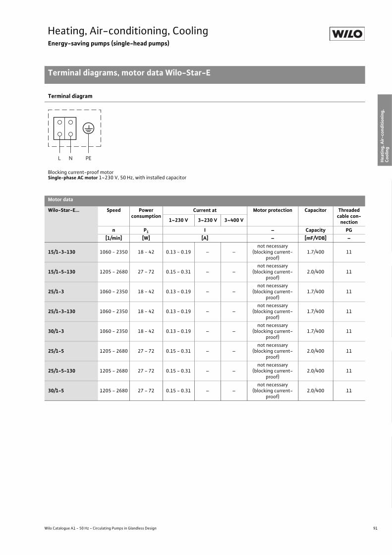
91
Heating, Air-conditioning, CoolingEnergy-saving pumps (single-head pumps)
Terminal diagrams, motor data Wilo-Star-E
Wilo Catalogue A1 - 50 Hz - Circulating Pumps in Glandless Design
Hea
ting,
Air-
cond
ition
ing,
Co
olin
gSe
cond
ary
Hot W
ater
Circ
ulat
ion
Sola
r The
rmal
, Geo
ther
mal
En
ergy
Sys
tem
sSe
rvic
e/Ac
cess
orie
s, S
yste
ms
Switc
hgea
rs a
nd C
ontr
ol
Dev
ices
Pum
p M
anag
emen
t Sys
tem
s
Terminal diagram
Blocking current-proof motorSingle-phase AC motor 1~230 V, 50 Hz, with installed capacitor
Motor data
Wilo-Star-E... Speed Power consumption
Current at Motor protection Capacitor Threaded cable con-
nection1~230 V 3~230 V 3~400 V
n P1 I – Capacity PG[1/min] [W] [A] – [mF/VDB] –
15/1-3-130 1060 - 2350 18 - 42 0.13 - 0.19 – –not necessary
(blocking current-proof)
1.7/400 11
15/1-5-130 1205 - 2680 27 - 72 0.15 - 0.31 – –not necessary
(blocking current-proof)
2.0/400 11
25/1-3 1060 - 2350 18 - 42 0.13 - 0.19 – –not necessary
(blocking current-proof)
1.7/400 11
25/1-3-130 1060 - 2350 18 - 42 0.13 - 0.19 – –not necessary
(blocking current-proof)
1.7/400 11
30/1-3 1060 - 2350 18 - 42 0.13 - 0.19 – –not necessary
(blocking current-proof)
1.7/400 11
25/1-5 1205 - 2680 27 - 72 0.15 - 0.31 – –not necessary
(blocking current-proof)
2.0/400 11
25/1-5-130 1205 - 2680 27 - 72 0.15 - 0.31 – –not necessary
(blocking current-proof)
2.0/400 11
30/1-5 1205 - 2680 27 - 72 0.15 - 0.31 – –not necessary
(blocking current-proof)
2.0/400 11
L N PE

92 Subject to change without prior notice 09/2007 WILO AG
Heating, Air-conditioning, CoolingEnergy-saving pumps (single-head pumps)
Dimensions, weights Wilo-Star-E
Dimension drawing
Dimensions, weights
Wilo-Star-E... Pipe connection/nominal diameter
Thread Pump dimensions Weight about
Rp G a1 I0 l1 l2 l3 l4 b0 b1 b2 b3 –– – [mm] [kg]
15/1-3-130 Rp 1/2 G 1 33 130 96 65 78 160 93 106 56 74 2.2
15/1-5-130 Rp 1/2 G 1 33 130 96 65 78 160 93 106 56 74 2.5
25/1-3 Rp 1 G 1 1/2 33 180 96 90 78 160 93 106 56 74 2.4
25/1-3-130 Rp 1 G 1 1/2 33 130 96 65 78 160 93 106 56 74 2.2
25/1-5 Rp 1 G 1 1/2 33 180 96 90 78 160 93 106 56 74 2.7
25/1-5-130 Rp 1 G 1 1/2 33 130 96 65 78 160 93 106 56 74 2.5
30/1-3 Rp 1 1/4 G 2 33 180 96 90 78 160 93 106 56 74 2.6
30/1-5 Rp 1 1/4 G 2 33 180 96 90 78 160 93 106 56 74 2.8
G
b 3
l 0
l 2
b0
b1
b2
a1 l1
l3
l4
Rp/DN

The knowledge database from Wilo.
500 answers to FAQs.Used 9000 times in 14 days.
1001 new suggestions.For even more expert knowledge.
Did you know? The knowledge database from Wilo will give you good and quickadvice: with approx. 500 responses to the most frequently asked questions (FAQs)all about pumps, installations and systems. It is already being visited extensively bymany skilled craftsmen.This is proven by 9000 utilisations in only 14 days, which werecently registered. The best thing: With every new question which you ask uswith the contact form, we all become wiser together. Because the correspondinganswer is naturally incorporated as soon as possible. Know-how? We call this Pumpen Intelligenz.
www.wilo.com
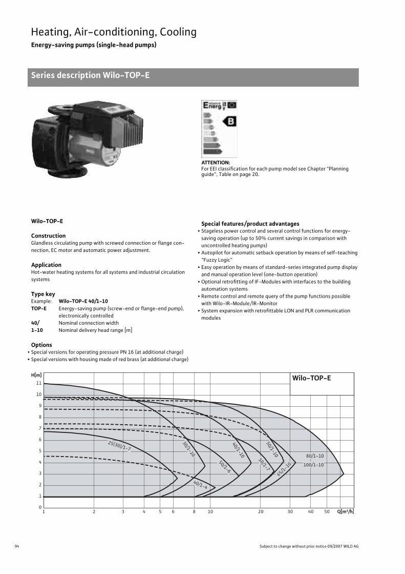
94 Subject to change without prior notice 09/2007 WILO AG
Heating, Air-conditioning, CoolingEnergy-saving pumps (single-head pumps)
Series description Wilo-TOP-E
Wilo-TOP-E
ConstructionGlandless circulating pump with screwed connection or flange con-nection, EC motor and automatic power adjustment.
ApplicationHot-water heating systems for all systems and industrial circulation systems
Type keyExample: Wilo-TOP-E 40/1-10TOP-E Energy-saving pump (screw-end or flange-end pump),
electronically controlled40/ Nominal connection width1-10 Nominal delivery head range [m]
Options• Special versions for operating pressure PN 16 (at additional charge)• Special versions with housing made of red brass (at additional charge)
Special features/product advantages• Stageless power control and several control functions for energy-
saving operation (up to 50% current savings in comparison with uncontrolled heating pumps)
• Autopilot for automatic setback operation by means of self-teaching “Fuzzy Logic”
• Easy operation by means of standard-series integrated pump display and manual operation level (one-button operation)
• Optional retrofitting of IF-Modules with interfaces to the building automation systems
• Remote control and remote query of the pump functions possible with Wilo-IR-Module/ IR-Monitor
• System expansion with retrofittable LON and PLR communication modules
ATTENTION:For EEI classification for each pump model see Chapter “Planning guide”, Table on page 20.
Q[m³/h]1 2 3 4 5 6 8 10 20 30 40 50
H[m]
0
1
2
3
4
5
6
7
8
9
10
11
40/1-4
40/1-10
50/1-750/1-10
65/1-10
80/1-10
100/1-10
30/1-10
50/1-6
25(30)/1-7
Wilo-TOP-E

95
Heating, Air-conditioning, CoolingEnergy-saving pumps (single-head pumps)
Series description Wilo-TOP-E
Wilo Catalogue A1 - 50 Hz - Circulating Pumps in Glandless Design
Hea
ting,
Air-
cond
ition
ing,
Co
olin
gSe
cond
ary
Hot W
ater
Circ
ulat
ion
Sola
r The
rmal
, Geo
ther
mal
En
ergy
Sys
tem
sSe
rvic
e/Ac
cess
orie
s, S
yste
ms
Switc
hgea
rs a
nd C
ontr
ol
Dev
ices
Pum
p M
anag
emen
t Sys
tem
s
Equipment/function
Operating modes• Manual control mode (n=constant)• �p-c for constant differential pressure• �p-v for variable differential pressure• �p-T for temperature-controlled differential pressure (programma-
ble via IR-Module, IR-Monitor or LON)
Manual functions• Setting the operating mode• Setting the differential-pressure setpoint• Setting to “Autopilot” (automatic setback operation)• Setting the pump to ON/OFF• Setting the speed (manual setting mode)
Automatic functions• Stageless power adjustment depending on the operating mode• “Autopilot” automatic setback operation• Deblocking function• Soft start
(not with TOP-E 25(30)/1-7, TOP-E 30/1-10, TOP-E 40/1-4 and TOP-E 50/1-6)
• Full motor protection with integrated trip electronics
External control functions• Control input “Overriding Off” (not with TOP-E 25(30)/1-7, TOP-E
30/1-10, TOP-E 40/1-4 and TOP-E 50/1-6)• Control input “Analogue In 0 - 10 V” (remote speed adjustment)
(not with TOP-E 25(30)/1-7, TOP-E 30/1-10, TOP-E 40/1-4 and TOP-E 50/1-6)
Signal and display functions• Collective fault signal (potential-free NC contact)• Fault signal light• LC display for showing pump data and fault codes
Data exchange• Infrared interface for wireless data exchange with IR-Module/IR-Monitor• Serial digital PLR interface for connection to BA building automation
via Wilo interface converter or company-specific coupling module Possible with IF-Modules (accessories)
• Serial digital LON interface for connection to a LONWorks network; Possible with IF-Modules (accessories)
Dual pump management (twin-head pump or 2 x single-head pumps)• Main/standby operation (automatic fault-actuated switchover/me-
sensitive pump alteration): Different combinations with IF-Modules (accessories) possible
• Parallel operation (efficiency-optimised peak-load cut-in and out): Different combinations with IF-Modules (accessories) possible
Equipment/scope of delivery• Plug-in slot for optional expansion with Wilo-IF-Modules• Including seals for threaded connection (loose)• Including installation and operating instructions• Including thermal insulation• Including washers for flange bolts (for nominal connection widths
DN 32 - DN 65)
Accessories• Screwed connections with screw thread• IR-Module• IR-Monitor• IF-Modules: PLR, LON• Analogue interface converter AnaCon• Digital interface converter DigiCon/DigiCon-A

96 Subject to change without prior notice 09/2007 WILO AG
Heating, Air-conditioning, CoolingEnergy-saving pumps (single-head pumps)
Technical data Wilo-TOP-E
Wilo-TOP-E...
25/1
-7
30/1
-7
30/1
-10
40/1
-4
40/1
-10
50/1
-6
50/1
-7
50/1
-10
65/1
-10
80/1
-10
100/
1-10
Approved fluids(other fluids on request)
Heating water (as per VDI 2035) • • • • • • • • • • •Water/glycol mixtures (maximum 1:1; mixtures with more than 20 % glycol content require rechecking of the pumping data)
• • • • • • • • • • •
Secondary hot water and water for food businesses as per TrinkwV 2001 – – – – – – – – – – –
Performance
Maximum delivery head [m] 7 7 11 4 10 7 7 10 9 10 10
Maximum flow volume [m3/h] 6.5 6.5 9 11 18 15 24 27 32 62 62
Permitted field of application
Temperature range for utilisation in heating, ventila-tion & air conditioning systems
for maximum ambient temperature +25 °C [°C]for maximum ambient temperature +40 °C [°C]
–+20 to +110
Temperature range for application in secondary hot water-circulation systems [°C]
with maximum ambient temperature of +40 °C [°C] – – – – – – – – – – –
Maximum permissible total hardness in secondary hot water-circulation systems [°d] – – – – – – – – – – –
Standard version for operating pressure pmax [bar] 10 10 10 6/10 6/10 6/10 6/10 6/10 6/10 6 6
Special version for operating pressure pmax [bar] – – 16 – 16 16 16 16 1610 10
16 16
Pipe connections
Screwed connection Rp 1 1 1/4 1 1/4 – – – – – – – –
Nominal connection diameter DN – – – 40 40 50 50 50 65 80 100
Flange for counter flange PN 6, standard version – – – – – – – – – • •Counter flange for PN 16, flange, special version – – – – • • • • • • •Combination flange PN 6/10 for counter flange PN 6 and PN 16, standard version – – – • • • • • • – –
Support-bracket mounting (with horizontal shaft only), standard version – – – – – – – – – – –
Support-bracket mounting (with horizontal shaft only), special version – – – – – – – – – – –
Electrical connection
Mains connection 1~ [V], standard version 230 230 230 230 230 230 230 230 230 230 230
Mains connection 3~ [V], standard version 230 230 230 230 230 230 230 230 230 230 230
Mains connection 3~ [V], with optional switching plug – – – – – – – – – – –
Mains frequency [Hz] 50 50 50 50 50 50 50 50 50 50 50
• = available, – = not available

97
Heating, Air-conditioning, CoolingEnergy-saving pumps (single-head pumps)
Technical data Wilo-TOP-E
Wilo Catalogue A1 - 50 Hz - Circulating Pumps in Glandless Design
Hea
ting,
Air-
cond
ition
ing,
Co
olin
gSe
cond
ary
Hot W
ater
Circ
ulat
ion
Sola
r The
rmal
, Geo
ther
mal
En
ergy
Sys
tem
sSe
rvic
e/Ac
cess
orie
s, S
yste
ms
Switc
hgea
rs a
nd C
ontr
ol
Dev
ices
Pum
p M
anag
emen
t Sys
tem
s
Motor/electronics
Electromagnetic compatibility EN 61800-3
Emitted interference EN 61000-6-3
Immunity to interference EN 61000-6-2
Power electronics High-frequency PWM procedure
Fre-quency conv.
High-fre-
quency PWM
proce-dure
Frequency converter
Protection class IP 43 IP 43 IP 43 IP 43 IP 43 IP 43 IP 43 IP 43 IP 43 IP 43 IP 43
Insulation class F F F F F F F F F F F
Materials
Pump housing
Cast iron (EN-GJL-200)
TOP-E 30/1-7:Also as special version
in red brass (CC 491K)
Cast iron (EN-GJL-250)
TOP-E 50/1-7, TOP-E 65/1-10, TOP E-80/1-10:Also as special version in red brass (CC 491K)
Impeller Plastic (PP - 50% GF)
Shaft Stainless steel (X46 Cr13)
Bearing Metal-impregnated carbon
Minimum suction head at suction port [m]for the prevention of cavitation at water delivery temperature
50 °C 0.5 0.5 0.5 0.5 0.5 0.5 3 3 3 3 3
95 °C 5 5 5 5 5 5 10 10 10 10 10
110 °C 11 11 11 11 11 11 16 16 16 16 16
Wilo-TOP-E...
25/1
-7
30/1
-7
30/1
-10
40/1
-4
40/1
-10
50/1
-6
50/1
-7
50/1
-10
65/1
-10
80/1
-10
100/
1-10
• = available, – = not available

98 Subject to change without prior notice 09/2007 WILO AG
Heating, Air-conditioning, CoolingEnergy-saving pumps (single-head pumps)
Pump curves Wilo-TOP-E
Wilo-TOP-E 25/1-7, 30/1-7
�p-c (constant) �p-v (variable)
Wilo-TOP-E 30/1-10
�p-c (constant) �p-v (variable)
Pump curves Wilo-TOP-E
Pump curves
200
175
150
125
100
75
50
25
0
0 0,5 1 1,5
0 5 10 15 20
0 0,5 1 1,5 2 Rp 11/4
0 1 2 3 4 5 6
0 1 2 3 4 5 6
Q
[m3/h]
[lgpm]
7
6
5
4
3
2
1
0
[l/s]
[m3/h]
0 1 2 3 Rp 1v
[m/s]
min.
max.
∆ p-c
max.
1 m2 m
3 m4 m5 m
6 m
Wilo-TOP-E 25/1-7Wilo-TOP-E 30/1-71 ~ 230 V - Rp 1/Rp 11/4
min.P 1[W]
H[m
]
200
175
150
125
100
75
50
25
0
0 0,5 1 1,5
0 5 10 15 20
0 0,5 1 1,5 2 Rp 11/4
0 1 2 3 4 5 6
0 1 2 3 4 5 6
Q
[m3/h]
[lgpm]
7
6
5
4
3
2
1
0
[l/s]
[m3/h]
0 1 2 3 Rp 1v
[m/s]
max.
max.
2 m3 m4 m5 m
6 m
min.
? p-v
Wilo-TOP-E 25/1-7Wilo-TOP-E 30/1-71 ~ 230 V - Rp 1/Rp 11/4
min.P 1[W]
H[m
]
400
300
200
100
0
0 0,5 1 1,5 2 2,5
0 5 10 15 20 25 30 35
0 1 2 3 4 5 6 7 8 9
0 1 2 3 4 5 6 7 8 9
Q
[m3/h]
[lgpm]
12
11
10
9
8
7
6
5
4
3
2
1
0
[l/s]
[m3/h]
min.
max.
� p-c
max.
1 m
2 m
4 m6 m
Wilo-TOP-E 30/1-10 1 ~ 230 V - Rp 11/4
0 0,5 1 1,5 2 2,5 3v
[m/s]
8 m
10 m
min.
P 1[W]
H[m
]
400
300
200
100
0
0 0,5 1 1,5 2 2,5
0 5 10 15 20 25 30 35
0 1 2 3 4 5 6 7 8 9
0 1 2 3 4 5 6 7 8 9
Q
[m3/h]
[lgpm]
12
11
10
9
8
7
6
5
4
3
2
1
0
[l/s]
[m3/h]
min.
max.
? p-v
max.
8 m 4 m
6 m
Wilo-TOP-E 30/1-10 1 ~ 230 V - Rp 11/4
0 0,5 1 1,5 2 2,5 3v
[m/s]
min.10 m
P 1[W]
H[m
]

99
Heating, Air-conditioning, CoolingEnergy-saving pumps (single-head pumps)
Pump curves Wilo-TOP-E
Wilo Catalogue A1 - 50 Hz - Circulating Pumps in Glandless Design
Hea
ting,
Air-
cond
ition
ing,
Co
olin
gSe
cond
ary
Hot W
ater
Circ
ulat
ion
Sola
r The
rmal
, Geo
ther
mal
En
ergy
Sys
tem
sSe
rvic
e/Ac
cess
orie
s, S
yste
ms
Switc
hgea
rs a
nd C
ontr
ol
Dev
ices
Pum
p M
anag
emen
t Sys
tem
s
Wilo-TOP-E 40/1-4
�p-c (constant) �p-v (variable)
Wilo-TOP-E 40/1-10
�p-c (constant) �p-v (variable)
225
200
175
150
125
100
75
50
25
0
0 1 2 3
0 10 20 30
0 0,5 1 1,5 2
0 2 4 6 8 10
0 2 4 6 8 10
v[m/s]
Q
[m3/h]
[lgpm]
5
4
3
2
1
0
[l/s]
[m3/h]
max.
Wilo-TOP-E 40/1-4 1 ~ 230 V - DN 40
max.
� p-c
min.
2 m
1 m3 m
min.
P 1[W]
H[m
]
225
200
175
150
125
100
75
50
25
0
0 1 2 3
0 10 20 30
0 0,5 1 1,5 2
0 2 4 6 8 10
0 2 4 6 8 10
v[m/s]
Q
[m3/h]
[lgpm]
5
4
3
2
1
0
[l/s]
[m3/h]
max.
Wilo-TOP-E 40/1-4 1 ~ 230 V - DN 40
max.
� p-c
min.
2 m
1 m3 m
min.
P 1[W]
H[m
]
700
600
500
400
300
200
100
0
0 1 2 3 4
0 10 20 30 40 50
0 0,5 1 1,5 2 2,5 3
0 2 4 6 8 10 12 14 16
0 2 4 6 8 10 12 14 16
v[m/s]
Q
[m3/h]
[lgpm]
10
9
8
7
6
5
4
3
2
1
0
[l/s]
[m3/h]
max.
3 m
1 m
5 m7 m
max.
min.
� p-c Wilo-TOP-E 40/1-10 1 ~ 230 V - DN 40
min.
P 1[W]
H[m
]
0 1 2 3 4
0 10 20 30 40 50
0 0,5 1 1,5 2 2,5 3
0 2 4 6 8 10 12 14 16
0 2 4 6 8 10 12 14 16
v[m/s]
Q
[m3/h]
[lgpm]
10
9
8
7
6
5
4
3
2
1
0
[l/s]
[m3/h]
min.
max.
5m8m
6m
7m
min.
� p-v
4m
max.
Wilo-TOP-E 40/1-10 1 ~ 230 V - DN 40
700
600
500
400
300
200
100
0
P 1[W]
H[m
]

100 Subject to change without prior notice 09/2007 WILO AG
Heating, Air-conditioning, CoolingEnergy-saving pumps (single-head pumps)
Pump curves Wilo-TOP-E
Wilo-TOP-E 50/1-6
�p-c (constant) �p-v (variable)
Wilo-TOP-E 50/1-7
�p-c (constant) �p-v (variable)
450
400
350
300
250
200
150
100
50
0
0 1 2 3 4
0 10 20 30 40 50
0 0,5 1 1,5
0 2 4 6 8 10 12 14
v[m/s]
Q
[m3/h]
[lgpm]
8
7
6
5
4
3
2
1
0
[l/s]
[m3/h]
max.
max.
� p-c
min.
2 m
1 m
3 m4 m
5 m6 m
min.
Wilo-TOP-E 50/1-6 1 ~ 230 V - DN 50
0 2 4 6 8 10 12 14
P 1[W]
H[m
]
450
400
350
300
250
200
150
100
50
0
0 1 2 3 4
0 10 20 30 40 50
0 2 4 6 8 10 12 14
Q
[m3/h]
[lgpm]
8
7
6
5
4
3
2
1
0
[l/s]
[m3/h]
max.
max.
�p-v
min.
2 m
3 m4 m5 m
min.
0 0,5 1 1,5 v
[m/s]
6 m
0 2 4 6 8 10 12 14
Wilo-TOP-E 50/1-6 1 ~ 230 V - DN 50
P 1[W]
H[m
]
700
600
500
400
300
200
100
0
0 1 2 3 4 5 6
0 10 20 30 40 50 60 70 80
0 5 10 15 20
0 5 10 15 20
Q
[m3/h]
[lgpm]
8
7
6
5
4
3
2
1
0
[l/s]
[m3/h]
min.
max.
� p-c
max.
1 m2 m
3 m
4 m
6 m
0 1 2 3v
[m/s]
min.
Wilo-TOP-E 50/1-7 1 ~ 230 V - DN 50
5 mP 1[W]
H[m
]
700
600
500
400
300
200
100
0
0 1 2 3 4 5 6
0 10 20 30 40 50 60 70 80
0 5 10 15 20
0 5 10 15 20
Q
[m3/h]
[lgpm]
8
7
6
5
4
3
2
1
0
[l/s]
[m3/h]
min.
max.
� p-v
max.
3 m4 m
5 m
6 m
0 1 2 3v
[m/s]
min.
Wilo-TOP-E 50/1-7 1 ~ 230 V - DN 50
P 1[W]
H[m
]

101
Heating, Air-conditioning, CoolingEnergy-saving pumps (single-head pumps)
Pump curves Wilo-TOP-E
Wilo Catalogue A1 - 50 Hz - Circulating Pumps in Glandless Design
Hea
ting,
Air-
cond
ition
ing,
Co
olin
gSe
cond
ary
Hot W
ater
Circ
ulat
ion
Sola
r The
rmal
, Geo
ther
mal
En
ergy
Sys
tem
sSe
rvic
e/Ac
cess
orie
s, S
yste
ms
Switc
hgea
rs a
nd C
ontr
ol
Dev
ices
Pum
p M
anag
emen
t Sys
tem
s
Wilo-TOP-E 50/1-10
�p-c (constant) �p-v (variable)
Wilo-TOP-E 65/1-10
�p-c (constant) �p-v (variable)
1000
800
600
400
200
0
0 1 2 3 4 5 6 7
0 10 20 30 40 50 60 70 80 90
0 1 2 3
0 5 10 15 20 25
0 5 10 15 20 25
v[m/s]
Q
[m3/h]
[lgpm]
10
9
8
7
6
5
4
3
2
1
0
[l/s]
[m3/h]
min.
� p-c
1 m
3 m
min.
5 m
7 m
max.
9 m
max.
Wilo-TOP-E 50/1-10 1 ~ 230 V - DN 50
P 1[W]
H[m
]
1000
800
600
400
200
0
0 1 2 3 4 5 6 7
0 10 20 30 40 50 60 70 80 90
0 1 2 3
0 5 10 15 20 25
0 5 10 15 20 25
v[m/s]
Q
[m3/h]
[lgpm]
10
9
8
7
6
5
4
3
2
1
0
[l/s]
[m3/h]
min.
� p-v
4 m
7 m
min.
5 m6 m
max.
8 m
max.
Wilo-TOP-E 50/1-10 1 ~ 230 V - DN 50
P 1[W]
H[m
]
1000
800
600
400
200
0
0 2 4 6 8
0 25 50 75 100
0 0,5 1 1,5 2
0 5 10 15 20 25 30
0 5 10 15 20 25 30
v[m/s]
Q
[m3/h]
[lgpm]
9
8
7
6
5
4
3
2
1
0
[l/s]
[m3/h]
max.
max.
� p-c
min.
5 m7 m
3 m
min.
1 m
Wilo-TOP-E 65/1-10 1 ~ 230 V - DN 65
P 1[W]
H[m
]
1000
800
600
400
200
0
0 2 4 6 8
0 25 50 75 100
0 0,5 1 1,5 2
0 5 10 15 20 25 30
0 5 10 15 20 25 30
v[m/s]
Q
[m3/h]
[lgpm]
9
8
7
6
5
4
3
2
1
0
[l/s]
[m3/h]
max.
� p-v
min.
5 m
7 m
4 m
min.
6 m
max.
Wilo-TOP-E 65/1-10 1 ~ 230 V - DN 65
P 1[W]
H[m
]

102 Subject to change without prior notice 09/2007 WILO AG
Heating, Air-conditioning, CoolingEnergy-saving pumps (single-head pumps)
Pump curves Wilo-TOP-E
Wilo-TOP-E 80/1-10
�p-c (constant) �p-v (variable)
Wilo-TOP-E 100/1-10
�p-c (constant) �p-v (variable)
1800
1600
1400
1200
1000
800
600
400
200
0
0 2 4 6 8 10 12 14 16 18
0 50 100 150 200
0 0,5 1 1,5 2 2,5 3
0 10 20 30 40 50 60
0 10 20 30 40 50 60
v[m/s]
Q
[m3/h]
[lgpm]
10
9
8
7
6
5
4
3
2
1
0
[l/s]
[m3/h]
min.
� p-c
1 m
3 m
min.
5 m7 m
9 m
max.
max.
Wilo-TOP-E 80/1-10 1 ~ 230 V - DN 80
P 1[W]
H[m
]
1800
1600
1400
1200
1000
800
600
400
200
0
0 2 4 6 8 10 12 14 16 18
0 50 100 150 200
0 0,5 1 1,5 2 2,5 3
0 10 20 30 40 50 60
0 10 20 30 40 50 60
v[m/s]
Q
[m3/h]
[lgpm]
10
9
8
7
6
5
4
3
2
1
0
[l/s]
[m3/h]
min.
� p-v
4 m
min.
5 m7 m
max.
max.
6 m
Wilo-TOP-E 80/1-10 1 ~ 230 V - DN 80
8 m
P 1[W]
H[m
]
1800
1600
1400
1200
1000
800
600
400
200
0
0 2 4 6 8 10 12 14 16 18
0 50 100 150 200
0 0,5 1 1,5
0 10 20 30 40 50 60
0 10 20 30 40 50 60
v[m/s]
Q
[m3/h]
[lgpm]
10
9
8
7
6
5
4
3
2
1
0
[l/s]
[m3/h]
min.
� p-c
1m
3m5m
7m9m
max.
max.
Wilo-TOP-E 100/1-10 1 ~ 230 V - DN 100
min.
P 1[W]
H[m
]
1800
1600
1400
1200
1000
800
600
400
200
0
0 2 4 6 8 10 12 14 16 18
0 50 100 150 200
0 0,5 1 1,5
0 10 20 30 40 50 60
0 10 20 30 40 50 60
v[m/s]
Q
[m3/h]
[lgpm]
10
9
8
7
6
5
4
3
2
1
0
[l/s]
[m3/h]
min.
� p-v
4m
min.
5m7m
8m
max.
max.
6m
Wilo-TOP-E 100/1-10 1 ~ 230 V - DN 100
P 1[W]
H[m
]

103
Heating, Air-conditioning, CoolingEnergy-saving pumps (single-head pumps)
Terminal diagrams, motor data Wilo-TOP-E
Wilo Catalogue A1 - 50 Hz - Circulating Pumps in Glandless Design
Hea
ting,
Air-
cond
ition
ing,
Co
olin
gSe
cond
ary
Hot W
ater
Circ
ulat
ion
Sola
r The
rmal
, Geo
ther
mal
En
ergy
Sys
tem
sSe
rvic
e/Ac
cess
orie
s, S
yste
ms
Switc
hgea
rs a
nd C
ontr
ol
Dev
ices
Pum
p M
anag
emen
t Sys
tem
s
Terminal diagram A Terminal diagram B
DP: Dual pump management (2 pumps)PLR: Serial digital BA interfaceLON: Serial digital LONWorks interfaceSSM Collective fault signal
(normally closed contact as per VDI 3814, load capacity 1 A,250 V ~) for function, see Chapter “Pump managementWilo-Control, Planning guide”
DP: Dual pump management (2 pumps)PLR: Serial digital BA interfaceLON: Serial digital LONWorks interfaceSSM Collective fault signal
(normally closed contact as per VDI 3814, load capacity 1 A,250 V ~) for function, see Chapter “Pump managementWilo-Control, Planning guide”
�/In: Control input 0 - 10 V for speed-controller operation+24V: Auxiliary voltageExt. off: Control input override “Off” for ext. potential-free
contact (normally closed contact):Contact closed: Pump enabled,contact open: Pump “Off”
Motor data
Wilo-TOP-E... Nominal power
Speed Power consumption
Current at Motor protection
Threaded cable connection
Terminal diagram1~230V 3~230V 3~400V
P2 n P1 I – PG –[W] [1/min] [W] [A] – – –
25/1-7 90 1000 – 2800 30 – 200 0.2 – 0.9 0.20 – 0.90 – integrated 1 x 7 / 1 x 11 / 1 x 13.5 A30/1-7 90 1000 – 2800 30 – 200 0.2 – 0.9 0.20 – 0.90 – integrated 1 x 7 / 1 x 11 / 1 x 13.5 A30/1-10 180 900 – 2800 45 – 400 0.25 – 1.8 0.25 – 1.80 – integrated 1 x 7 / 1 x 11 / 1 x 13.5 A40/1-4 90 1250 – 2700 60 – 200 0.3 – 0.9 0.30 – 0.90 – integrated 1 x 7 / 1 x 11 / 1 x 13.5 A40/1-10 350 850 – 2850 25 – 625 0.18 – 2.75 0.18 – 2.75 – integrated 1 x 7 / 1 x 11 / 1 x 13.5 B50/1-6 180 1000 – 2800 70 – 390 0.35 – 1.7 0.35 – 1.70 – integrated 1 x 7 / 1 x 11 / 1 x 13.5 A50/1-7 350 850 – 2850 25 – 645 0.18 – 2.81 0.18 – 2.81 – integrated 1 x 7 / 1 x 11 / 1 x 13.5 B50/1-10 450 850 – 2850 30 – 930 0.28 – 4.1 0.28 – 4.10 – integrated 1 x 7 / 1 x 11 / 1 x 13.5 B65/1-10 570 850 – 2850 35 – 980 0.27– 4.31 0.27– 4.31 – integrated 1 x 7 / 1 x 11 / 1 x 13.5 B80/1-10 1100 850 – 2850 60 – 1650 0.33 – 7.2 0.33 – 7.20 – integrated 1 x 7 / 1 x 11 / 1 x 13.5 B100/1-10 1100 850 – 2850 60 – 1650 0.33 – 7.2 0.33 – 7.20 – integrated 1 x 7 / 1 x 11 / 1 x 13.5 B
Standard
PLR
DP
Option: IF-Module PLR
DP
LON
Option: IF-Module LON
L N PE SSM L1 L3
L2 L3
L1 L2
PE SSM
1~ 230 V, 50 Hz
3~ 230 V, 50 Hz
0… 10V
Standard
PLR
DP
Option: IF-Module PLR
DP
LON
Option: IF-Module LON
L N PE SSMIn +24V Ext. off L1 L3
L2 L3
L1 L2
PE SSM
1~ 230 V, 50 Hz
3~ 230 V, 50 Hz

104 Subject to change without prior notice 09/2007 WILO AG
Heating, Air-conditioning, CoolingEnergy-saving pumps (single-head pumps)
Dimensions, weights Wilo-TOP-E
Dimension drawing A Dimension drawing B
Permitted installation positions, see Planning guide Permitted installation positions, see Planning guide
Dimension drawing C Dimension drawing D
Permitted installation positions, see Planning guide Permitted installation positions, see Planning guide
Dimension drawing E Dimension drawing F Dimension drawing G
Rp
l 2
a3
l 1
b1 b2
b3 b3
G a2
a1
l 0
Pg b4 b5
Rp
l 2
a3b1 b2
b3 b3
G a2
a1
l 0l 1
Pgb4 b5
l 2
b1
b3 b3
a2
l 0
l 1
a3 a1
Pg
b2
R 1/8
b4 b5
l 2
b1 b2
b3 b3
a2
l 0
l 1
a3 a1
Pg
R 1/8
b4 b5
R 1/8
b1 b2
b4 b5
b3 b3
Pg
a2
a1a3
l 0
l 1
l 2
Ø D
n x Ø d
Ø k
DN
L2Ø k Ø d
L 1
1
n x Ø d 2n x Ø d
Ø D Ø k
DN
Ø d
L

105
Heating, Air-conditioning, CoolingEnergy-saving pumps (single-head pumps)
Dimensions, weights Wilo-TOP-E
Wilo Catalogue A1 - 50 Hz - Circulating Pumps in Glandless Design
Hea
ting,
Air-
cond
ition
ing,
Co
olin
gSe
cond
ary
Hot W
ater
Circ
ulat
ion
Sola
r The
rmal
, Geo
ther
mal
En
ergy
Sys
tem
sSe
rvic
e/Ac
cess
orie
s, S
yste
ms
Switc
hgea
rs a
nd C
ontr
ol
Dev
ices
Pum
p M
anag
emen
t Sys
tem
s
Dimensions, weights
Wilo-TOP-E... Pipe connection/
nominaldiameter
Thread Pump dimensions
Weightabout
Dimen-sional
drawing
Rp/DN G I0 l1 l2 a1 a2 a3 b1 b2 b3 b4 b5 PN 6/10 –– – [mm] [kg] –
25/1-7 Rp 1 G 1 1/2 180 90 123 225 34 56 66 57 80 52 76 5.5 A
30/1-7 Rp 1 1/4 G 2 180 90 123 232 34 64 66 57 88 56 76 5.5 A
30/1-10 Rp 1 1/4 G 2 180 90 131 257 40 68 73 66 93 56 83 7.5 B
40/1-4 40 – 220 110 123 237 54 76 83 60 103 52 76 10.0 C
40/1-10 40 – 250 125 160 306 57 88 90 87 115 77 87 15.5 E
50/1-6 50 – 240 120 133 275 39 82 78 62 112 56 83 13.0 D
50/1-7 50 – 280 140 160 314 63 82 91 74 119 77 87 17.5 E
50/1-10 50 – 280 140 190 337 69 91 101 86 123 77 87 19.5 E
65/1-10 65 – 340 170 200 368 79 100 118 98 136 77 87 26.0 E
80/1-10 80 – 360 180 200 371 95 130 135 135 159 77 87 30.5/32.5 E
100/1-10 100 – 360 180 200 371 95 130 135 135 159 77 87 31.0/33.0 E
Flange dimensions
Wilo-TOP-E... Flange Nominal diameter
Pump flange dimensions
Dimen-sional
drawing– DN Ø D Ø d Ø kL1/kL2 Ø k n x Ø dL1/dL2 n x Ø dL –– – [mm] [pcs. x mm] [pcs. x mm] –
40/1-440/1-10
Combination flange PN 6/10(flange PN 16, as per DIN 2533) 40 150 88 100/110 – 4 x 14/19 – F
50/1-650/1-750/1-10
Combination flange PN 6/10(flange PN 16, as per DIN 2533) 50 165 102 110/125 – 4 x 14/19 – F
65/1-10 Combination flange PN 6/10(flange PN 16, as per DIN 2533) 65 185 122 130/145 – 4 x 14/19 – F
80/1-10
Flange PN 6 (as per DIN DIN 2531) 80 190 128 – 150 – 4 x 19 G
Flange PN 16(as per DIN 2533, drilled as per EN 1092-2)
80 200 138 – 160 – 8 x 19 G
100/1-10
Flange PN 6 (as per DIN DIN 2531) 100 210 148 – 170 – 4 x 19 G
Flange PN 16(as per DIN 2533, drilled as per EN 1092-2)
100 220 158 – 180 – 8 x 19 G
n = No. of bolt holes
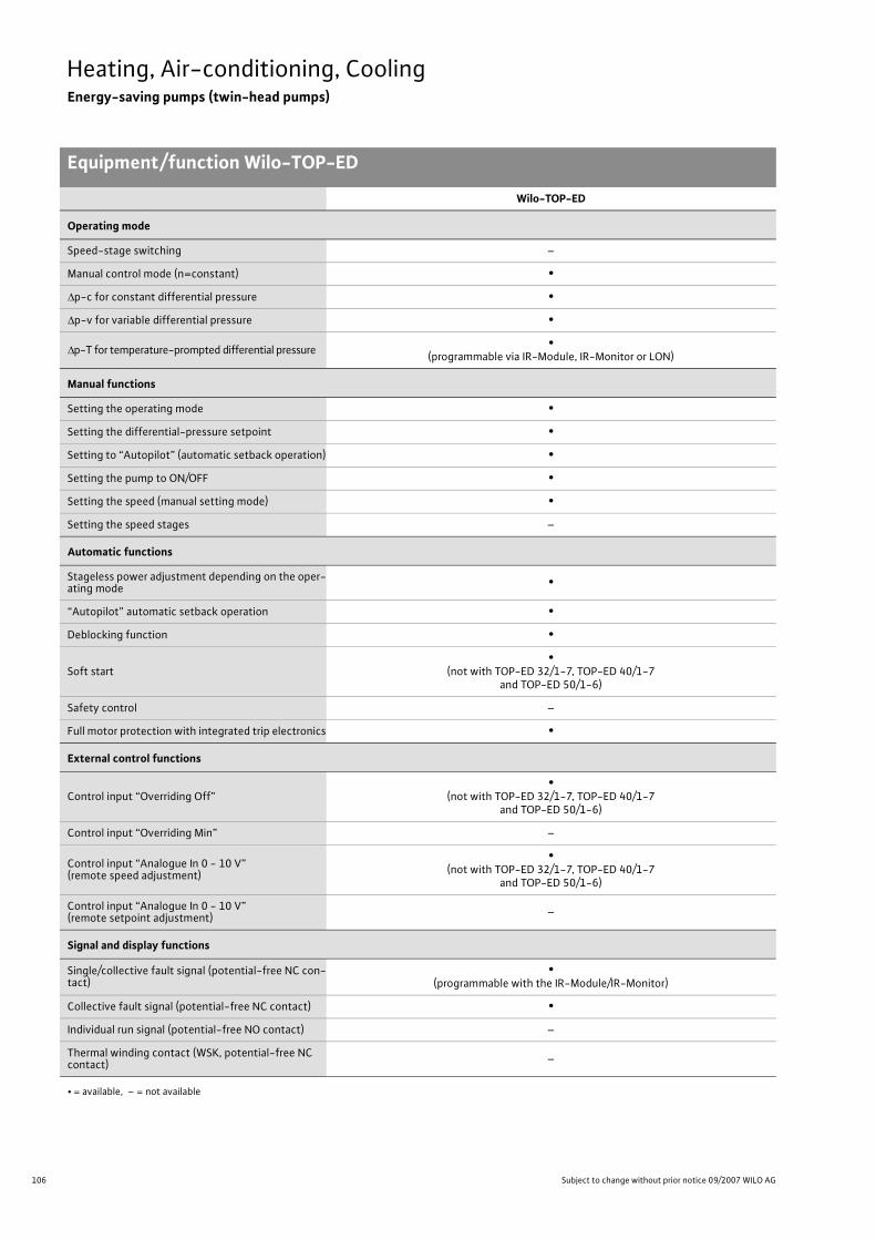
106 Subject to change without prior notice 09/2007 WILO AG
Heating, Air-conditioning, CoolingEnergy-saving pumps (twin-head pumps)
Equipment/function Wilo-TOP-ED
Wilo-TOP-ED
Operating mode
Speed-stage switching –
Manual control mode (n=constant) •�p-c for constant differential pressure •�p-v for variable differential pressure •
�p-T for temperature-prompted differential pressure •(programmable via IR-Module, IR-Monitor or LON)
Manual functions
Setting the operating mode •Setting the differential-pressure setpoint •Setting to “Autopilot” (automatic setback operation) •Setting the pump to ON/OFF •Setting the speed (manual setting mode) •Setting the speed stages –
Automatic functions
Stageless power adjustment depending on the oper-ating mode •
“Autopilot” automatic setback operation •Deblocking function •
Soft start•
(not with TOP-ED 32/1-7, TOP-ED 40/1-7and TOP-ED 50/1-6)
Safety control –
Full motor protection with integrated trip electronics •
External control functions
Control input “Overriding Off”•
(not with TOP-ED 32/1-7, TOP-ED 40/1-7and TOP-ED 50/1-6)
Control input “Overriding Min” –
Control input “Analogue In 0 - 10 V” (remote speed adjustment)
•(not with TOP-ED 32/1-7, TOP-ED 40/1-7
and TOP-ED 50/1-6)
Control input “Analogue In 0 - 10 V” (remote setpoint adjustment) –
Signal and display functions
Single/collective fault signal (potential-free NC con-tact)
•(programmable with the IR-Module/IR-Monitor)
Collective fault signal (potential-free NC contact) •Individual run signal (potential-free NO contact) –
Thermal winding contact (WSK, potential-free NC contact) –
• = available, – = not available

107
Heating, Air-conditioning, CoolingEnergy-saving pumps (twin-head pumps)
Equipment/function Wilo-TOP-ED
Wilo Catalogue A1 - 50 Hz - Circulating Pumps in Glandless Design
Hea
ting,
Air-
cond
ition
ing,
Co
olin
gSe
cond
ary
Hot W
ater
Circ
ulat
ion
Sola
r The
rmal
, Geo
ther
mal
En
ergy
Sys
tem
sSe
rvic
e/Ac
cess
orie
s, S
yste
ms
Switc
hgea
rs a
nd C
ontr
ol
Dev
ices
Pum
p M
anag
emen
t Sys
tem
s
Signal and display functions (continued)
Fault signal light •Direction-of-rotation control lamp –
LC display for showing pump data and fault codes •
Data exchange
Infrared interface for wireless data exchange with IR-Module/IR-Monitor (see IR-Module/IR-Monitor Function table)
•
Serial digital PLR interface for connection to BA building automation via Wilo interface converter or company-specific coupling module
•Possible with IF-Modules (accessories)
Serial digital LON interface for connection to a LONWorks network
•Possible with IF-Modules (accessories)
Serial digital CAN interface for connection to a CAN bus system –
Dual pump management (twin-head pump or 2 x single-head pump)(Dual pump management with 2 single-head pumps possible only if the equivalent tiwn-head pump is alsolisted in the Wilo Catalogue)
Main/standby operation (automatic fault-actuated switchover/time-sensitive pump alteration)
•Different combinations with IF-Modules (accessories) possible
(see Chapter “pump Management Wilo-Control”)
Parallel operation (efficiency-optimised peak-load cut-in and out)
•Different combinations with IF-Modules (accessories) possible
(see Chapter “pump Management Wilo-Control”)
Equipment/scope of delivery
Wrench attachment point on pump body –
Double switchover valve in pump housing •Cable entry possible on both sides –
Quick connection with spring clips –
Integrated air extraction fitting for automatic rapid ventilator Rp 3/8
–
Plug-in slot for optional expansion withWilo-IF-Modules •
Blocking current-proof motor –
Including seals for threaded connection (loose) –
Including installation and operating instructions •Including thermal insulation –
Including washers for flange bolts(for nominal connection widths DN 32 - DN 65) •
Incl. 1.8 m power cable with grounding plug –
Integrated non-return valve –
Integrated ball shutoff valve –
Including clock timer –
Wilo-TOP-ED
• = available, – = not available

108 Subject to change without prior notice 09/2007 WILO AG
Heating, Air-conditioning, CoolingEnergy-saving pumps (twin-head pumps)
Equipment/function Wilo-TOP-ED

109
Heating, Air-conditioning, CoolingEnergy-saving pumps (twin-head pumps)
Series description Wilo-TOP-ED
Wilo Catalogue A1 - 50 Hz - Circulating Pumps in Glandless Design
Hea
ting,
Air-
cond
ition
ing,
Co
olin
gSe
cond
ary
Hot W
ater
Circ
ulat
ion
Sola
r The
rmal
, Geo
ther
mal
En
ergy
Sys
tem
sSe
rvic
e/Ac
cess
orie
s, S
yste
ms
Switc
hgea
rs a
nd C
ontr
ol
Dev
ices
Pum
p M
anag
emen
t Sys
tem
s
Wilo-TOP-ED
Wilo-TOP-ED
ConstructionGlandless twin-head circulating pump with flange connection and automatic power adjustment
ApplicationHot-water heating systems for all systems and industrial circulation systems
Type keyExample: Wilo-TOP-ED 40/1-10TOP-ED Energy-saving pump (flange twin-head pump),
electronically controlled40/ Nominal connection width1-10 Nominal delivery head range [m]
Options• Special versions for operating pressure PN 16 (at additional charge)
Special features/Product advantages• Stageless power control and several control functions for energy-
saving operation (up to 50% current savings in comparison with uncontrolled heating pumps)
• Autopilot for automatic setback operation by means of self-teaching “Fuzzy Logic”
• Easy operation by means of standard-series integrated pump display and manual operation level (one-button operation)
• Optional retrofitting of IF-Modules with interfaces to the building automation systems
• Remote control and remote query of the pump functions possible with Wilo-IR-Module/ IR-Monitor
• System expansion with retrofittable LON and PLR communication modules
• Integrable dual pump management through retrofittable IF-Modules for:- Main/standby operation with fault-dependent switchover- Efficiency-optimised peak-load operation
ATTENTION:For EEI classification for each pump model see Chapter “Planning guide”, Table on page 20.
Q[m³/h]1 2 3 5 64 8 10 20 30 40 50 60
H[m]
0
1
2
3
4
5
6
7
8
9
10
32/1-7
40/1-10
40/1-750/1-6 50/1-7
50/1-10
65/1-10
80/1-10
Wilo-TOP-ED+
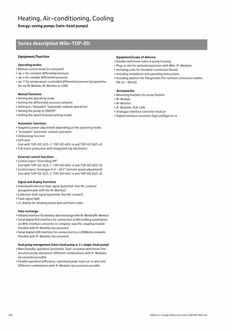
110 Subject to change without prior notice 09/2007 WILO AG
Heating, Air-conditioning, CoolingEnergy-saving pumps (twin-head pumps)
Series description Wilo-TOP-ED
Equipment/function
Operating modes• Manual control mode (n=constant)• �p-c for constant differential pressure• �p-v for variable differential pressure• �p-T for temperature-controlled differential pressure (programma-
ble via IR-Module, IR-Monitor or LON)
Manual functions• Setting the operating mode• Setting the differential-pressure setpoint• Setting to “Autopilot” (automatic setback operation)• Setting the pump to ON/OFF• Setting the speed (manual setting mode)
Automatic functions• Stageless power adjustment depending on the operating mode• “Autopilot” automatic setback operation• Deblocking function• Soft start
(not with TOP-ED 32/1-7, TOP-ED 40/1-4 and TOP-ED 50/1-6)• Full motor protection with integrated trip electronics
External control functions• Control input “Overriding Off”
(not with TOP-ED 32/1-7, TOP-ED 40/1-4 and TOP-ED 50/1-6)• Control input “Analogue In 0 - 10 V” (remote speed adjustment)
(not with TOP-ED 32/1-7, TOP-ED 40/1-4 and TOP-ED 50/1-6)
Signal and display functions• Individual/collective fault signal (potential-free NC contact)
(programmable with the IR-Monitor)• Collective fault signal (potential-free NC contact)• Fault signal light• LC display for showing pump data and fault codes
Data exchange• Infrared interface for wireless data exchange with IR-Module/IR-Monitor• Serial digital PLR interface for connection to BA building automation
via Wilo interface converter or company-specific coupling module Possible with IF-Modules (accessories)
• Serial digital LON interface for connection to a LONWorks network; Possible with IF-Modules (accessories)
Dual pump management (twin-head pump or 2 x single-head pump)• Main/standby operation (automatic fault-actuated switchover/me-
sensitive pump alteration): Different combinations with IF-Modules (accessories) possible
• Parallel operation (efficiency-optimised peak-load cut-in and out): Different combinations with IF-Modules (accessories) possible
Equipment/scope of delivery• Double switchover valve in pump housing• Plug-in slot for optional expansion with Wilo-IF-Modules• Including seals for threaded connection (loose)• Including installation and operating instructions• Including washers for flange bolts (for nominal connection widths
DN 32 - DN 65)
Accessories• Mounting brackets for pump fixation• IR-Module• IR-Monitor• IF-Modules: PLR, LON• Analogue interface converter AnaCon• Digital interface converter DigiCon/DigiCon-A

111
Heating, Air-conditioning, CoolingEnergy-saving pumps (twin-head pumps)
Technical data Wilo-TOP-ED
Wilo Catalogue A1 - 50 Hz - Circulating Pumps in Glandless Design
Hea
ting,
Air-
cond
ition
ing,
Co
olin
gSe
cond
ary
Hot W
ater
Circ
ulat
ion
Sola
r The
rmal
, Geo
ther
mal
En
ergy
Sys
tem
sSe
rvic
e/Ac
cess
orie
s, S
yste
ms
Switc
hgea
rs a
nd C
ontr
ol
Dev
ices
Pum
p M
anag
emen
t Sys
tem
s
Wilo-TOP-ED...
32/1-7 40/1-7 40/1-10 50/1-6 50/1-7 50/1-10 65/1-10 80/1-10
Approved fluids(other fluids on request)
Heating water (as per VDI 2035) • • • • • • • •Water/glycol mixtures (maximum 1:1; mixtures with more than 20 % glycol content require rechecking of the pumping data)
• • • • • • • •
Secondary hot water and water for food businesses as per TrinkwV 2001 – – – – – – – –
Performance
Maximum delivery head [m] 7 7 10 7 7 10 9 10
Maximum flow volume [m3/h] 10 23 27 24 39 43 59 93
Permitted field of application
Temperature range for utilisation in HVAC systemswith maximum ambient temperature +25 °C [°C]with maximum ambient temperature +40 °C [°C]
–+20 to +110
Temperature range for utilisation in secondary hot water circulation systems
at maximum ambient temperature +40 °C [°C] – – – – – – – –
Maximum permissible total hardness in secondary hot water-circulation systems [°d] – – – – – – – –
Standard version for operating pressure pmax [bar] 6/10 6/10 6/10 6/10 6/10 6/10 6/10 6
Special version for operating pressure pmax [bar] – 16 16 16 16 16 1610
16
Pipe connections
Screwed connection Rp – – – – – – – –
Nominal connection diameter DN 32 40 40 50 50 50 65 80
Flange for counter flange PN 6, standard version – – – – – – – •Counter flange for PN 16, flange, special version – • • • • • • •Combination flange PN 6/10 for counter flange PN 6 and PN 16, standard version • • • • • • • –
Support-bracket mounting (with horizontal shaft only), standard version – – – – – – • •
Support-bracket mounting (with horizontal shaft only), special version – • • • • • – –
Electrical connection
Mains connection 1~ [V], standard version 230 230 230 230 230 230 230 230
Mains connection 3~ [V], standard version 230 230 230 230 230 230 230 230
Mains connection 3~ [V], with optional switching plug – – – – – – – –
Mains frequency [Hz] 50 50 50 50 50 50 50 50
• = available, – = not available

112 Subject to change without prior notice 09/2007 WILO AG
Heating, Air-conditioning, CoolingEnergy-saving pumps (twin-head pumps)
Technical data Wilo-TOP-ED
Motor/electronics
Electromagnetic compatibility EN 61800-3
Emitted interference EN 61000-6-3
Immunity to interference EN 61000-6-2
Power electronics High-frequency PWM procedure
Fre-quency
converter
High-fre-quency
PWM pro-cedure
Frequency converter
Protection class IP 43 IP 43 IP 43 IP 43 IP 43 IP 43 IP 43 IP 43
Insulation class F F F F F F F F
Materials
Pump housing Cast iron (EN-GJL-250)
Impeller Plastic (PP - 50% GF)
Shaft Stainless steel (X46 Cr13)
Bearing Metal-impregnated carbon
Minimum suction head at suction port [m]for the prevention of cavitation at water delivery temperature
50 °C 0.5 0.5 0.5 0.5 3 3 3 3
95 °C 5 5 5 5 10 10 10 10
110 °C 11 11 11 11 16 16 16 16
Wilo-TOP-ED...
32/1-7 40/1-7 40/1-10 50/1-6 50/1-7 50/1-10 65/1-10 80/1-10
• = available, – = not available
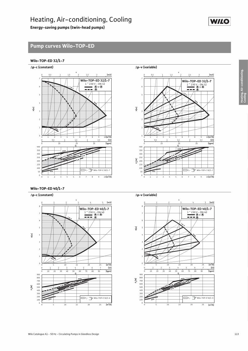
113
Heating, Air-conditioning, CoolingEnergy-saving pumps (twin-head pumps)
Pump curves Wilo-TOP-ED
Wilo Catalogue A1 - 50 Hz - Circulating Pumps in Glandless Design
Hea
ting,
Air-
cond
ition
ing,
Co
olin
gSe
cond
ary
Hot W
ater
Circ
ulat
ion
Sola
r The
rmal
, Geo
ther
mal
En
ergy
Sys
tem
sSe
rvic
e/Ac
cess
orie
s, S
yste
ms
Switc
hgea
rs a
nd C
ontr
ol
Dev
ices
Pum
p M
anag
emen
t Sys
tem
s
Wilo-TOP-ED 32/1-7
�p-c (constant) �p-v (variable)
Wilo-TOP-ED 40/1-7
�p-c (constant) �p-v (variable)
400
350
300
250
200
150
100
50
0
0 0,5 1 1,5 2 2,5
0 10 20 30
0 1 2 3 4 5 6 7 8 9 10
0 1 2 3 4 5 6 7 8 9 10
Q
[m3/h]
[lgpm]
7
6
5
4
3
2
1
0
[l/s]
[m3/h]
max.
� p-c
max.
1 m
2 m3 m4 m6 m
Wilo-TOP-ED 32/1-7 1 ~ 230 V - DN 32
0 0,5 1 1,5 2 2,5 3v
[m/s]
P1- Wilo-TOP-E 30/1-7
min.
min.
5 m
H[m
]
+
400
350
300
250
200
150
100
50
0
0 0,5 1 1,5 2 2,5
0 10 20 30
0 1 2 3 4 5 6 7 8 9 10
0 1 2 3 4 5 6 7 8 9 10
Q
[m3/h]
[lgpm]
7
6
5
4
3
2
1
0
[l/s]
[m3/h]
min.
max.
� p-v
2 m3 m
4 m5 m6 m
max.
Wilo-TOP-ED 32/1-7 1 ~ 230 V - DN 32
0 0,5 1 1,5 2 2,5 3v
[m/s]
P1- Wilo-TOP-E 30/1-7min.
P 1[W]
H[m
]
+
900
800
700
600
500
400
300
200
100
0
0 1 2 3 4 5 6 7
0 10 20 30 40 50 60 70 80 90
0 1 2 3 4 5
0 5 10 15 20 25
0 5 10 15 20 25
v[m/s]
Q
[m3/h]
[lgpm]
8
7
6
5
4
3
2
1
0
[l/s]
[m3/h]
max.
� p-c
min.
1 m
2 m3 m
4 m5 m
6 m
Wilo-TOP-ED 40/1-7 1 ~ 230 V - DN 40
P1- Wilo-TOP-E 50/1-6
max.
min.
+
P 1[W]
H[m
]
900
800
700
600
500
400
300
200
100
0
0 1 2 3 4 5 6 7
0 10 20 30 40 50 60 70 80 90
0 5 10 15 20 25
0 5 10 15 20 25
Q
[m3/h]
[m3/h]
[lgpm]
8
7
6
5
4
3
2
1
0
[l/s]
max.
� p-v
2 m
3 m4 m
5 m
min.
0 1 2 3 4 5v
[m/s]
Wilo-TOP-ED 40/1-7 1 ~ 230 V - DN 40
min.
max.
P1- Wilo-TOP-E 50/1-6
6 m
P 1[W]
H[m
]
+

114 Subject to change without prior notice 09/2007 WILO AG
Heating, Air-conditioning, CoolingEnergy-saving pumps (twin-head pumps)
Pump curves Wilo-TOP-ED
Wilo-TOP-ED 40/1-10
�p-c (constant) �p-v (variable)
Wilo-TOP-ED 50/1-6
�p-c (constant) �p-v (variable)
1200
1000
800
600
400
200
0
0 1 2 3 4 5 6 7
0 25 50 75
0 1 2 3 4 5
0 5 10 15 20 25
0 5 10 15 20 25
v[m/s]
Q
[m3/h]
[lgpm]
11
10
9
8
7
6
5
4
3
2
1
0
[l/s]
[m3/h]min.
� p-c
2 m
3 m
min.
4 m
5 m6 m
max.
max.
8 m
1 m
Wilo-TOP-ED 40/1-10 1 ~ 230 V - DN 40
P1- Wilo-TOP-E 40/1-10
7 m
+
P 1[W]
H[m
]
1200
1000
800
600
400
200
0
0 1 2 3 4 5 6 7
0 25 50 75
0 1 2 3 4 5
0 5 10 15 20 25
0 5 10 15 20 25
v [m/s]
Q
[m3/h]
[lgpm]
11
10
9
8
7
6
5
4
3
2
1
0
[l/s]
[m3/h]
min.
min.
4 m
5 m6 m7 m
max.
8 m
max.
� p-v
Wilo-TOP-ED 40/1-10 1 ~ 230 V - DN 40
P1- Wilo-TOP-E 40/1-10
P 1[W]
H[m
]
+
900
800
700
600
500
400
300
200
100
0
0 1 2 3 4 5 6 7
0 10 20 30 40 50 60 70 80 90
0 1 2 3
0 5 10 15 20 25
0 5 10 15 20 25
v[m/s]
Q
[m3/h]
[lgpm]
8
7
6
5
4
3
2
1
0
[l/s]
[m3/h]
� p-c
min.
1 m3 m
4 m5 m
6 m
Wilo-TOP-ED 50/1-6 1 ~ 230 V - DN 50
max.
P1- Wilo-TOP-E 50/1-6min.
max.
2 m
+
P 1[W]
H[m
]
900
800
700
600
500
400
300
200
100
0
0 1 2 3 4 5 6 7
0 10 20 30 40 50 60 70 80 90
0 1 2 3
0 5 10 15 20 25
0 5 10 15 20 25
v [m/s]
Q
[m3/h]
[lgpm]
8
7
6
5
4
3
2
1
0
[l/s]
[m3/h]
max.
max.
� p-v
2 m
3 m4 m
min.
Wilo-TOP-ED 50/1-6 1 ~ 230 V - DN 50
min. P1- Wilo-TOP-E 50/1-6
6 m 5 m
P 1[W]
H[m
]
+

115
Heating, Air-conditioning, CoolingEnergy-saving pumps (twin-head pumps)
Pump curves Wilo-TOP-ED
Wilo Catalogue A1 - 50 Hz - Circulating Pumps in Glandless Design
Hea
ting,
Air-
cond
ition
ing,
Co
olin
gSe
cond
ary
Hot W
ater
Circ
ulat
ion
Sola
r The
rmal
, Geo
ther
mal
En
ergy
Sys
tem
sSe
rvic
e/Ac
cess
orie
s, S
yste
ms
Switc
hgea
rs a
nd C
ontr
ol
Dev
ices
Pum
p M
anag
emen
t Sys
tem
s
Wilo-TOP-ED 50/1-7
�p-c (constant) �p-v (variable)
Wilo-TOP-ED 50/1-10
�p-c (constant) �p-v (variable)
1400
1200
1000
800
600
400
200
0
0 2 4 6 8 10
0 20 40 60 80 100 120
0 5 10 15 20 25 30 35
0 5 10 15 20 25 30 35
Q
[m3/h]
[lgpm]
8
7
6
5
4
3
2
1
0
[l/s]
[m3/h]
max.
� p-c
min.
1 m
2 m3 m4 m
5 m6 m
min.
max.
Wilo-TOP-ED 50/1-7 1 ~ 230 V - DN 50
P1- Wilo-TOP-E 50/1-7
0 0,5 1 1,5 2 2,5 3 3,5 4 4,5 v
[m/s]
P 1[W]
H[m
]
+
1400
1200
1000
800
600
400
200
0
0 2 4 6 8 10
0 20 40 60 80 100 120
0 0,5 1 1,5 2 2,5 3 3,5 4 4,5
0 5 10 15 20 25 30 35
0 5 10 15 20 25 30 35
v[m/s]
Q
[m3/h]
[lgpm]
8
7
6
5
4
3
2
1
0
[l/s]
[m3/h]
Wilo-TOP-ED 50/1-7 1 ~ 230 V - DN 50
max.
� p-v
min.
3 m
6 m
min.
max.
P1- Wilo-TOP-E 50/1-7
5 m 4 m
P 1[W]
H[m
]
+
200018001600140012001000
800600400200
0
0 2 4 6 8 10
0 25 50 75 100 125
0 1 2 3 4 5
0 5 10 15 20 25 30 35 40
0 5 10 15 20 25 30 35 40
v[m/s]
Q
[m3/h]
[lgpm]
10
9
8
7
6
5
4
3
2
1
0
[l/s]
[m3/h]min.
max.
� p-c
2 m
max.
min.
6 m7 m
P1- Wilo-TOP-E 50/1-10
8 m
5 m4 m
1 m
3 m
Wilo-TOP-ED 50/1-10 1 ~ 230 V - DN 50
P 1[W]
H[m
]
+
200018001600140012001000
800600400200
0
0 2 4 6 8 10
0 25 50 75 100 125
0 1 2 3 4 5
0 5 10 15 20 25 30 35 40
0 5 10 15 20 25 30 35 40
v [m/s]
Q
[m3/h]
[lgpm]
10
9
8
7
6
5
4
3
2
1
0
[l/s]
[m3/h]
min.
max.
� p-v
5 m
max.
6 m
min.
7 m
Wilo-TOP-ED 50/1-10 1 ~ 230 V - DN 50
P1- Wilo-TOP-E 50/1-10
4 m
8 mP 1[W]
H[m
]
+

116 Subject to change without prior notice 09/2007 WILO AG
Heating, Air-conditioning, CoolingEnergy-saving pumps (twin-head pumps)
Pump curves Wilo-TOP-ED
Wilo-TOP-ED 65/1-10
�p-c (constant) �p-v (variable)
Wilo-TOP-ED 80/1-10
�p-c (constant) �p-v (variable)
2000
1600
1200
800
400
0
0 2 4 6 8 10 12 14
0 20 40 60 80 100 120 140 160 180
0 0,5 1 1,5 2 2,5 3 3,5 4
0 10 20 30 40 50
0 10 20 30 40 50
v [m/s]
Q
[m3/h]
[lgpm]
9
8
7
6
5
4
3
2
1
0
[l/s]
[m3/h]
min.
max.
� p-c
min.
5 m6 m7 m
2 m
1 m
3 m4 m
Wilo-TOP-ED 65/1-10 1 ~ 230 V - DN 65
P1- Wilo-TOP-E 65/1-10
max.
P 1[W]
H[m
]
+
2000
1600
1200
800
400
0
0 10 20 30 40 50
0 10 20 30 40 50
Q
[m3/h]
9
8
7
6
5
4
3
2
1
0
[m3/h]
max.
� p-v
min.
6 m
4 m5 m
min.
max.
0 2 4 6 8 10 12 14
0 20 40 60 80 100 120 140 160 180 [lgpm]
[l/s]
7 m
0 0,5 1 1,5 2 2,5 3 3,5 4v
[m/s]
P1- Wilo-TOP-E 65/1-10
Wilo-TOP-ED 65/1-10 1 ~ 230 V - DN 65
P 1[W]
H[m
]
+
4000
3000
2000
1000
0
0 4 8 12 16 20 24
0 40 80 120 160 200 240 280 320
0 1 2 3 4
0 10 20 30 40 50 60 70 80 90
0 10 20 30 40 50 60 70 80 90
v [m/s]
Q
[m3/h]
[lgpm]
10
9
8
7
6
5
4
3
2
1
0
[l/s]
[m3/h]
� p-c
1 m2 m
3 m
min.
4 m5 m
6 m7 m
max.
max.
Wilo-TOP-ED 80/1-10 1 ~ 230 V - DN 80
P1- Wilo-TOP-E 80/1-10
min.
8 m
P 1[W]
H[m
]
+
4000
3000
2000
1000
0
0 4 8 12 16 20 24
0 40 80 120 160 200 240 280 320
0 1 2 3 4
0 10 20 30 40 50 60 70 80 90
0 10 20 30 40 50 60 70 80 90
v [m/s]
Q
[m3/h]
[lgpm]
10
9
8
7
6
5
4
3
2
1
0
[l/s]
[m3/h]
� p-v
min.
4 m5 m6 m
7 m8 m
max.
max.
Wilo-TOP-ED 80/1-10 1 ~ 230 V - DN 80
min.P1- Wilo-TOP-E 80/1-10
P 1[W]
H[m
]
+

117
Heating, Air-conditioning, CoolingEnergy-saving pumps (twin-head pumps)
Terminal diagrams, motor data Wilo-TOP-ED
Wilo Catalogue A1 - 50 Hz - Circulating Pumps in Glandless Design
Hea
ting,
Air-
cond
ition
ing,
Co
olin
gSe
cond
ary
Hot W
ater
Circ
ulat
ion
Sola
r The
rmal
, Geo
ther
mal
En
ergy
Sys
tem
sSe
rvic
e/Ac
cess
orie
s, S
yste
ms
Switc
hgea
rs a
nd C
ontr
ol
Dev
ices
Pum
p M
anag
emen
t Sys
tem
s
Terminal diagram A Terminal diagram B
DP: Dual pump management (2 pumps)PLR: Serial digital BA interfaceLON: Serial digital LONWorks interfaceSSM Collective fault signal
(normally closed contact as per VDI 3814, load capacity 1 A,250 V ~) for function, see Chapter “Pump managementWilo-Control, Planning guide”
DP: Dual pump management (2 pumps)PLR: Serial digital BA interfaceLON: Serial digital LONWorks interfaceSSM Collective fault signal
(normally closed contact as per VDI 3814, load capacity 1 A,250 V ~) for function, see Chapter “Pump managementWilo-Control, Planning guide”
�/In: Control input 0 - 10 V for speed-controller operation+24V: Auxiliary voltageExt. off: Control input override “Off” for ext. potential-free
contact (normally closed contact):Contact closed: Pump enabled,contact open: Pump “Off”
Motor data
Wilo-TOP-ED... Nominalpower
Speed Power consumption
Current at Motorprotection
Threaded cable connection
Terminaldiagram1~230 V 3~230 V 3~400 V
P2 n P1 I – PG –[W] [1/min] [W] [A] – – –
32/1-7 90 1000 - 2800 30 - 200 0.2 - 0.9 0.2 - 0.9 – integrated 1 x 7 / 1 x 11 / 1 x 13.5 A
40/1-7 180 1000 - 2800 70 - 390 0.35 - 1.7 0.35 - 1.7 – integrated 1 x 7 / 1 x 11 / 1 x 13.5 A
40/1-10 350 850 - 2850 25 - 625 0.18 - 2.75 0.18 - 2.75 – integrated 1 x 7 / 1 x 11 / 1 x 13.5 B
50/1-6 180 1000 - 2800 70 - 390 0.35 - 1.7 0.35 - 1.7 – integrated 1 x 7 / 1 x 11 / 1 x 13.5 A
50/1-7 350 850 - 2850 25 - 645 0.18 - 2.81 0.18 - 2.81 – integrated 1 x 7 / 1 x 11 / 1 x 13.5 B
50/1-10 450 850 - 2850 30 - 930 0.28 - 4.1 0.28 - 4.1 – integrated 1 x 7 / 1 x 11 / 1 x 13.5 B
65/1-10 570 850 - 2850 35 - 980 0.27 - 4.31 0.27 - 4.31 – integrated 1 x 7 / 1 x 11 / 1 x 13.5 B
80/1-10 1100 850 - 2850 60 - 1650 0.33 - 7.2 0.33 - 7.2 – integrated 1 x 7 / 1 x 11 / 1 x 13.5 B
Standard
PLR
DP
Option: IF-Module PLR
DP
LON
Option: IF-Module LON
L N PE SSM L1 L3
L2 L3
L1 L2
PE SSM
1~ 230 V, 50 Hz
3~ 230 V, 50 Hz
0… 10V
Standard
PLR
DP
Option: IF-Module PLR
DP
LON
Option: IF-Module LON
L N PE SSMIn +24V Ext. off L1 L3
L2 L3
L1 L2
PE SSM
1~ 230 V, 50 Hz
3~ 230 V, 50 Hz
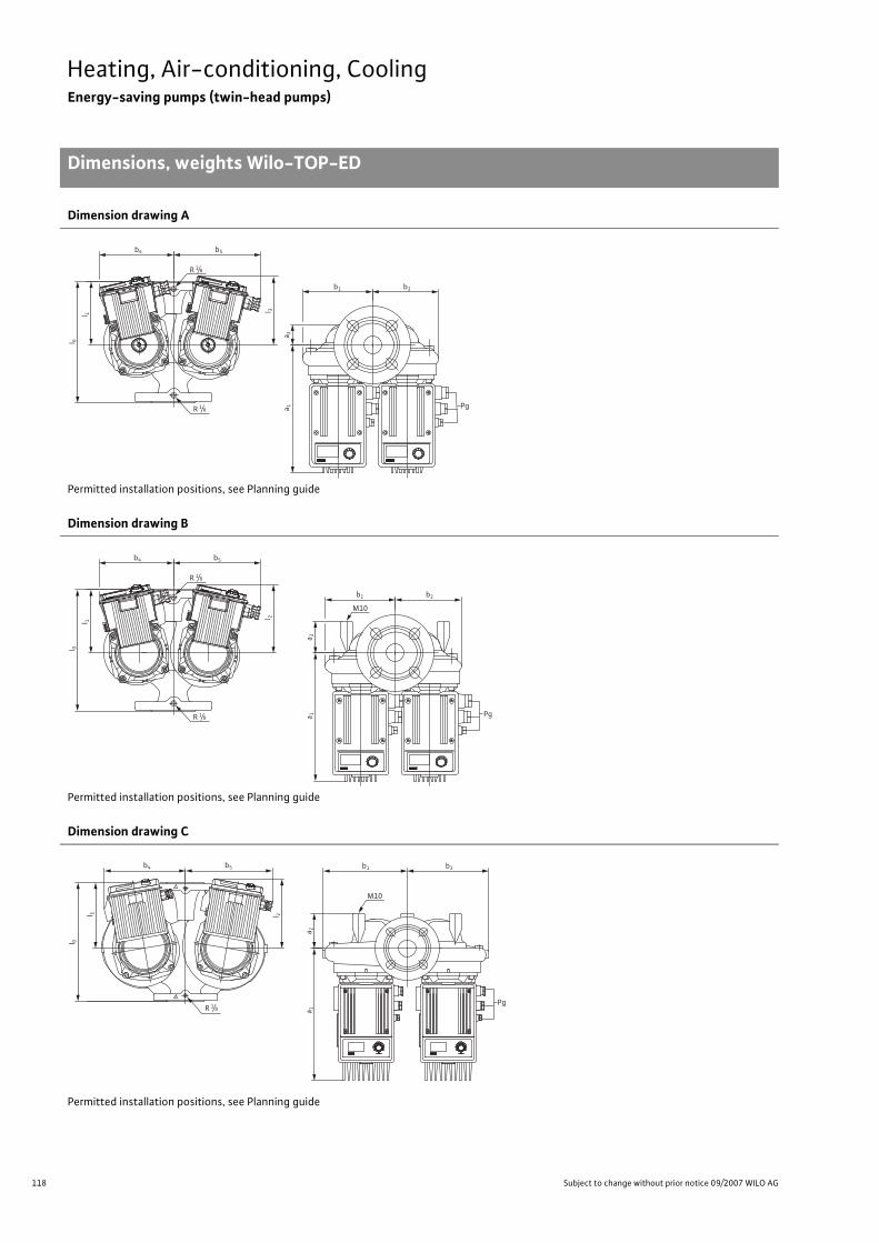
118 Subject to change without prior notice 09/2007 WILO AG
Heating, Air-conditioning, CoolingEnergy-saving pumps (twin-head pumps)
Dimensions, weights Wilo-TOP-ED
Dimension drawing A
Permitted installation positions, see Planning guide
Dimension drawing B
Permitted installation positions, see Planning guide
Dimension drawing C
Permitted installation positions, see Planning guide
l 0l 1
R 1/8
R 1/8
b4 b5
b1 b2
Pga 1a 2
l 3
R 1/8
R 1/8
l 0l 1
b4 b5
b1 b2
a 1a 2
l 2
M10
Pg
M10
R 1/8
b4 b5
l 0
l 1 l 2
b1 b2
a 1a 2
Pg

119
Heating, Air-conditioning, CoolingEnergy-saving pumps (twin-head pumps)
Dimensions, weights Wilo-TOP-ED
Wilo Catalogue A1 - 50 Hz - Circulating Pumps in Glandless Design
Hea
ting,
Air-
cond
ition
ing,
Co
olin
gSe
cond
ary
Hot W
ater
Circ
ulat
ion
Sola
r The
rmal
, Geo
ther
mal
En
ergy
Sys
tem
sSe
rvic
e/Ac
cess
orie
s, S
yste
ms
Switc
hgea
rs a
nd C
ontr
ol
Dev
ices
Pum
p M
anag
emen
t Sys
tem
s
Dimension drawing D Dimension drawing E
Dimension drawing F
Dimensions, weights
Wilo-TOP-ED... Nominal flange
diameter
Pump dimensions
Weight approxi-mately
Dimen-sional
drawingDN I0 l1 l2 a1 a2 b1 b2 b4 b5 y1 y2 z1 PN 6/10 –– [mm] [kg] –
32/1-7 32 220 115 124 232 38 127 120 135 158 – – – 15.0 A
40/1-7 40 250 135 133 266 75 145 135 152 175 108 11 172 22.0 B/F
40/1-10 40 250 135 165 306 75 178 172 182 195 132 35 225 32.0 C/F
50/1-6 50 280 160 132 275 83 149 139 152 175 113 11 172 24.0 B/F
50/1-7 50 280 160 165 314 83 179 169 182 195 132 30 225 33.5 C/F
50/1-10 50 280 155 192 337 83 198 192 192 215 157 50 228 38.0 C/F
65/1-10 65 340 185 203 368 93 223 209 202 226 162 25 225 51.0 C/F
80/1-10 80 360 205 202 371 100 249 231 219 234 180 43 240 59.5/61.0 C/F
Note for support-bracket mounting:For all bores with M10 threads for support-bracket mounting for versions TOP-ED 40 and TOP-ED 50 are obtainable upon request.
Ø D
n x Ø d
Ø k
DN
L2Ø k Ø d
L 1
1
n x Ø d 2n x Ø d
Ø D Ø k
DN
Ø d
L
z1
50
y 1
y 2
50
18
18
18
3030
30

120 Subject to change without prior notice 09/2007 WILO AG
Heating, Air-conditioning, CoolingEnergy-saving pumps (twin-head pumps)
Dimensions, weights Wilo-TOP-ED
Flange dimensions
Wilo-TOP-ED...Flange Nominal
diameter Pump flange dimensionsDimen-sional
drawing– DN Ø D Ø d Ø kL1/kL2 Ø k n x Ø dL1/dL2 n x Ø dL –– – [mm] [pcs. x mm] [pcs. x mm] –
32/1-7 Combination flange PN 6/10(flange PN 16, as per DIN 2533) 32 140 78 90/100 – 4 x 14/19 – D
40/1-740/1-10
Combination flange PN 6/10(flange PN 16, as per DIN 2533) 40 150 88 100/110 – 4 x 14/19 – D
50/1-650/1-750/1-10
Combination flange PN 6/10(flange PN 16, as per DIN 2533) 50 165 102 100/125 – 4 x 14/19 – D
65/1-10 Combination flange PN 6/10(flange PN 16, as per DIN 2533) 65 185 122 130/145 – 4 x 14/19 – D
80/1-10
Flange PN 6 (as per DIN 2531) 80 190 128 – 150 – 4 x 19 E
Flange PN 16(as per DIN 2533, drilled as per EN 1092-2)
80 200 138 – 150 – 8 x 19 E
n = No. of bolt holes
121
Heating, Air-conditioning, CoolingEnergy-saving pumps (twin-head pumps)
Dimensions, weights Wilo-TOP-ED
Wilo Catalogue A1 - 50 Hz - Circulating Pumps in Glandless Design
Hea
ting,
Air-
cond
ition
ing,
Co
olin
gSe
cond
ary
Hot W
ater
Circ
ulat
ion
Sola
r The
rmal
, Geo
ther
mal
En
ergy
Sys
tem
sSe
rvic
e/Ac
cess
orie
s, S
yste
ms
Switc
hgea
rs a
nd C
ontr
ol
Dev
ices
Pum
p M
anag
emen
t Sys
tem
s

122 Subject to change without prior notice 09/2007 WILO AG
Heating, Air-conditioning, CoolingAutomatic pumps (single-head pumps)
Series overview Wilo-Smart
Series: Wilo-Smart
> Single-head pumps:• Automatic circulating pumps with screw
connection> Application:• Hot-water heating systems for all systems
Wilo-Smart
Smart 25/30/4
Smart 25/30/6
00
1
2
3
4
5
10,5 21,5 3 Q[m³/h]2,5
H[m
]

123
Heating, Air-conditioning, CoolingAutomatic pumps (single-head pumps)
Series overview Wilo-Smart
Wilo Catalogue A1 - 50 Hz - Circulating Pumps in Glandless Design
Hea
ting,
Air-
cond
ition
ing,
Co
olin
gSe
cond
ary
Hot W
ater
Circ
ulat
ion
Sola
r The
rmal
, Geo
ther
mal
En
ergy
Sys
tem
sSe
rvic
e/Ac
cess
orie
s, S
yste
ms
Switc
hgea
rs a
nd C
ontr
ol
Dev
ices
Pum
p M
anag
emen
t Sys
tem
s
Series: Wilo-Smart
> Product advantages:• Simple pipe connection due to the safe and practical wrench attachment point on the pump
body.• Secure electrical connection through ergonomically optimised terminal box.
Quick connection with spring clips.• Easy operation. Ex-works setting suitable for 80 % of all heating systems requirements. Simple
selection of the 3 pre-programmed control channels is accomplished with the “red button”.• The automatic controller of the Wilo-Smart prevents flow noise in the heating system and
reduces electricity consumption.• Operational reliability due to automatic deblocking function. A special bronze filter prevents
particles from reaching the motor space.
>Additional information: Page:• Planning guide:. . . . . . . . . . . . . . . . . . . 6• Equipment/function:. . . . . . . . . . . . . . 124• Series description: . . . . . . . . . . . . . . . . 126• Technical data: . . . . . . . . . . . . . . . . . . . 128• Pump curves: . . . . . . . . . . . . . . . . . . . . 130• Terminal diagrams, motor data: . . . . 131• Dimensions, weights: . . . . . . . . . . . . . 131• Service/accessories: . . . . . . . . . . . . . . 393

124 Subject to change without prior notice 09/2007 WILO AG
Heating, Air-conditioning, CoolingAutomatic pumps (single-head pumps)
Equipment/function Wilo-Smart
Wilo-Smart
Operating modes
Speed-stage switching •Manual control mode (n=constant) –
Differential pressure control •�p-c for constant differential pressure •�p-v for variable differential pressure –
�p-T for temperature-controlled differential pressure –
Manual functions
Setting the operating mode –
Setting the differential-pressure setpoint –
Setting to “Autopilot”(automatic setback operation) –
Setting the pump to ON/OFF –
Setting the speed (manual setting mode) –
Setting the speed stages –
Setting the control channels 3
Automatic functions
Stageless power adjustment depending on the oper-ating mode –
“Autopilot” automatic setback operation –
Deblocking function •Soft start –
Safety control •Full motor protection with integrated trip electronics –
External control functions
Control input “Overriding Off” –
Control input “Overriding Min” –
Control input “Analogue In 0 - 10 V” (remote speed adjustment) –
Control input “Analogue In 0 - 10 V” (remote setpoint adjustment) –
Signal and display functions
Single/collective fault signal (potential-free NC con-tact) –
Collective fault signal (potential-free NC contact) –
Individual run signal (potential-free NO contact) –
Thermal winding contact (WSK, potential-free NC contact) –
• = available, – = not available

125
Heating, Air-conditioning, CoolingAutomatic pumps (single-head pumps)
Equipment/function Wilo-Smart
Wilo Catalogue A1 - 50 Hz - Circulating Pumps in Glandless Design
Hea
ting,
Air-
cond
ition
ing,
Co
olin
gSe
cond
ary
Hot W
ater
Circ
ulat
ion
Sola
r The
rmal
, Geo
ther
mal
En
ergy
Sys
tem
sSe
rvic
e/Ac
cess
orie
s, S
yste
ms
Switc
hgea
rs a
nd C
ontr
ol
Dev
ices
Pum
p M
anag
emen
t Sys
tem
s
Signal and display functions (continued)
Fault signal light –
Direction-of-rotation control lamp –
LC display for showing pump data and fault codes –
Data exchange
Infrared interface for wireless data exchange with IR-Module/ IR-Monitor (see IR-Module/ IR-Monitor Function table)
–
Serial digital PLR interface for connection to BA building automation via Wilo interface converter or company-specific coupling module
–
Serial digital LON interface for connection to a LONWorks network –
Serial digital CAN interface for connection to a CAN bus system –
Dual pump management (twin-head pump or 2 x single-head pumps)
Main/standby operation (automatic fault-actuated duty changeover/time-sensitive pump alteration) –
Parallel operation (efficiency-optimised peak-load cut-in and out) –
Equipment/scope of delivery
Wrench attachment point on pump body •Double switchover valve in pump housing –
Cable entry possible on both sides –
Wilo quick connection with spring clips •Integrated air extraction fitting for automatic rapid ventilator Rp 3/8
–
Plug-in slot for optional expansion with Wilo-IF-Modules –
Blocking current-proof motor •Particle filter •Including seals for threaded connection (loose) •Including installation and operating instructions •Including thermal insulation –
Including washers for flange bolts(for nominal connection widths DN 32 - DN 65) –
Incl. 1.8 m power cable with grounding plug –
Integrated non-return valve –
Integrated ball shutoff valve –
Including clock timer –
Wilo-Smart
• = available, – = not available
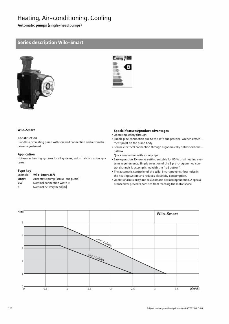
126 Subject to change without prior notice 09/2007 WILO AG
Heating, Air-conditioning, CoolingAutomatic pumps (single-head pumps)
Series description Wilo-Smart
Wilo-Smart
ConstructionGlandless circulating pump with screwed connection and automatic power adjustment
ApplicationHot-water heating systems for all systems, industrial circulation sys-tems
Type keyExample: Wilo-Smart 25/6Smart Automatic pump (screw-end pump)25/ Nominal connection width R6 Nominal delivery head [m]
Special features/product advantages• Operating safety through • Simple pipe connection due to the safe and practical wrench attach-
ment point on the pump body.• Secure electrical connection through ergonomically optimised termi-
nal box. Quick connection with spring clips.
• Easy operation. Ex-works setting suitable for 80 % of all heating sys-tems requirements. Simple selection of the 3 pre-programmed con-trol channels is accomplished with the “red button”.
• The automatic controller of the Wilo-Smart prevents flow noise in the heating system and reduces electricity consumption.
• Operational reliability due to automatic deblocking function. A special bronze filter prevents particles from reaching the motor space.
H[m]
0
1
2
3
4
5
Wilo-Smart
Smart 25/30/6
Smart 25/30/4
0 10,5 21,5 3 Q[m³/h]2,5 3,5

127
Heating, Air-conditioning, CoolingAutomatic pumps (single-head pumps)
Series description Wilo-Smart
Wilo Catalogue A1 - 50 Hz - Circulating Pumps in Glandless Design
Hea
ting,
Air-
cond
ition
ing,
Co
olin
gSe
cond
ary
Hot W
ater
Circ
ulat
ion
Sola
r The
rmal
, Geo
ther
mal
En
ergy
Sys
tem
sSe
rvic
e/Ac
cess
orie
s, S
yste
ms
Switc
hgea
rs a
nd C
ontr
ol
Dev
ices
Pum
p M
anag
emen
t Sys
tem
s
Equipment/function
Operating modes• Speed-stage switching• Differential pressure control• �p-c for constant differential pressure
Manual functions• Control channel adjustment (3 control channels)
Automatic functions• Deblocking function• Safety control
Equipment/scope of delivery• Wrench attachment point on pump body• Quick connection with spring clips• Blocking current-proof motor• Particle filter• Including seals for threaded connection (loose)• Including installation and operating instructions
Accessories• Screwed connections• Thermal insulation shells

128 Subject to change without prior notice 09/2007 WILO AG
Heating, Air-conditioning, CoolingAutomatic pumps (single-head pumps)
Technical data Wilo-Smart
Wilo-Smart...
25/4 25/6 30/4 30/6
Approved fluids(other fluids/media on request)
Heating water (as per VDI 2035) • • • •
Water/glycol mixtures (maximum 1:1; mixtures with more than 20% glycol content require rechecking of the pumping data)
• • • •
Secondary hot water and water for food businesses as per TrinkwV 2001 – – – –
Performance
Maximum delivery head [m] 4 6 4 6
Maximum flow volume [m3/h] 3 3.5 3 3.5
Permitted field of application
Temperature range for utilisation in HVAC systemswith maximum ambient temperature +25 °C [°C]with maximum ambient temperature +40 °C [°C]
–+2°C to +95°C
–+2°C to +95°C
–+2°C to +95°C
–+2°C to +95°C
Temperature range for utilisation in secondary hot water circulation systems
at maximum ambient temperature +40 °C [°C]– – – –
Maximum permissible total hardness in secondary hot water-circulation systems [°d] – – – –
Standard version for operating pressure pmax [bar] 10 10 10 10
Special version for operating pressure pmax [bar] – – – –
Pipe connections
Screwed connection Rp 1 1 1 1/4 1 1/4
Nominal connection diameter flange DN – – – –
Flange for counter flange PN 6, standard version – – – –
Flange for counter flange PN 16, special version – – – –
Combination flange PN 6/10 for counter flange PN 6 and PN 16, standard version – – – –
Support-bracket mounting (with horizontal shaft only), standard version – – – –
Support-bracket mounting (with horizontal shaft only), special version – – – –
Electrical connection
Mains connection 1~ [V], standard version 230 230 230 230
Mains connection 3~ [V], standard version – – – –
Mains connection 3~ [V], with optional switching plug – – – –
Mains frequency [Hz] 50 50 50 50
• = available, – = not available

129
Heating, Air-conditioning, CoolingAutomatic pumps (single-head pumps)
Technical data Wilo-Smart
Wilo Catalogue A1 - 50 Hz - Circulating Pumps in Glandless Design
Hea
ting,
Air-
cond
ition
ing,
Co
olin
gSe
cond
ary
Hot W
ater
Circ
ulat
ion
Sola
r The
rmal
, Geo
ther
mal
En
ergy
Sys
tem
sSe
rvic
e/Ac
cess
orie
s, S
yste
ms
Switc
hgea
rs a
nd C
ontr
ol
Dev
ices
Pum
p M
anag
emen
t Sys
tem
s
Motor/electronics
Electromagnetic compatibility EN 61800-3 EN 61800-3 EN 61800-3 EN 61800-3
Emitted interference EN 61000-6-3 EN 61000-6-3 EN 61000-6-3 EN 61000-6-3
Immunity to interference EN 61000-6-2 EN 61000-6-2 EN 61000-6-2 EN 61000-6-2
Power electronics – – – –
Protection class IP 42 IP 42 IP 42 IP 42
Insulation class F F F F
Materials
Pump housing Cast iron (EN-GJL-200)
Impeller Plastic (PP – 40% GF)
Shaft Stainless steel (X40 Cr13)
Bearing Metal-impregnated carbon
Minimum suction head at suction port [m]for the prevention of cavitation at water delivery temperature
50°C 0.5 0.5 0.5 0.5
95°C 3 3 3 3
Wilo-Smart...
25/4 25/6 30/4 30/6
• = available, – = not available

130 Subject to change without prior notice 09/2007 WILO AG
Heating, Air-conditioning, CoolingAutomatic pumps (single-head pumps)
Pump curves Wilo-Smart
Wilo-Smart 25/4, 30/4 Wilo-Smart 25/6, 30/6
H [m
]
0 0,5 1,0 1,5 2,0 2,5 3,0 3,5
0 0,5 1,0 1,5 2,0 2,5 3,0 3,5
0 0,25 0,5 0,75 1,0
0 2,5 5 7,5 10 12,5
5
4
3
2
1
0
50
40
30
20
Q
[l/s]
[lgpm]
[m3/h]
[m3/h]
P 1[W]
Wilo-Smart 25/4Wilo-Smart 30/41~230V - Rp1, Rp1¼
[m/s]0
0
0,5
0,5
1 1,5
1
vRp1
Rp1¼
H [m
]
[m/s]
Q
[l/s]
0 2,5 5 7,5 10 12,5 [lgpm]
[m3/h]
0 0,5 1,0 1,5 2,0 2,5 3,0 3,5 [m3/h]20
40
60
80
P 1[W]
Wilo-Smart 25/6Wilo-Smart 30/61~230V - Rp1, Rp1¼
0
0
0
1
2
3
4
5
6
0,5
0,5
1 1,5
1
0 0,5 1 21,5
0 0,25 0,5 0,75 1,0
2,5 3 3,5
vRp1
Rp1¼
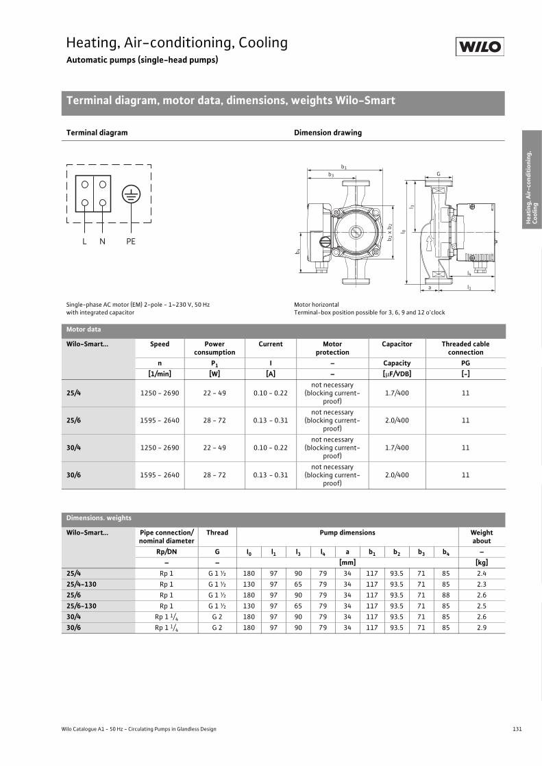
131
Heating, Air-conditioning, CoolingAutomatic pumps (single-head pumps)
Terminal diagram, motor data, dimensions, weights Wilo-Smart
Wilo Catalogue A1 - 50 Hz - Circulating Pumps in Glandless Design
Hea
ting,
Air-
cond
ition
ing,
Co
olin
gSe
cond
ary
Hot W
ater
Circ
ulat
ion
Sola
r The
rmal
, Geo
ther
mal
En
ergy
Sys
tem
sSe
rvic
e/Ac
cess
orie
s, S
yste
ms
Switc
hgea
rs a
nd C
ontr
ol
Dev
ices
Pum
p M
anag
emen
t Sys
tem
s
Terminal diagram Dimension drawing
Single-phase AC motor (EM) 2-pole - 1~230 V, 50 Hzwith integrated capacitor
Motor horizontalTerminal-box position possible for 3, 6, 9 and 12 o’clock
Motor data
Wilo-Smart... Speed Power consumption
Current Motor protection
Capacitor Threaded cable connection
n P1 I – Capacity PG[1/min] [W] [A] – [�F/VDB] [-]
25/4 1250 - 2690 22 - 49 0.10 - 0.22not necessary
(blocking current-proof)
1.7/400 11
25/6 1595 - 2640 28 - 72 0.13 - 0.31not necessary
(blocking current-proof)
2.0/400 11
30/4 1250 - 2690 22 - 49 0.10 - 0.22not necessary
(blocking current-proof)
1.7/400 11
30/6 1595 - 2640 28 - 72 0.13 - 0.31not necessary
(blocking current-proof)
2.0/400 11
Dimensions. weights
Wilo-Smart... Pipe connection/nominal diameter
Thread Pump dimensions Weightabout
Rp/DN G I0 l1 l3 l4 a b1 b2 b3 b4 –– – [mm] [kg]
25/4 Rp 1 G 1 ½ 180 97 90 79 34 117 93.5 71 85 2.425/4-130 Rp 1 G 1 ½ 130 97 65 79 34 117 93.5 71 85 2.325/6 Rp 1 G 1 ½ 180 97 90 79 34 117 93.5 71 88 2.625/6-130 Rp 1 G 1 ½ 130 97 65 79 34 117 93.5 71 85 2.530/4 Rp 1 1/4 G 2 180 97 90 79 34 117 93.5 71 85 2.630/6 Rp 1 1/4 G 2 180 97 90 79 34 117 93.5 71 85 2.9
L N PE
b1
b3 G
b 4
l 3
l4
l1a
l 0
b 2b 2
x

132 Subject to change without prior notice 09/2007 WILO AG
Heating, Air-conditioning, CoolingStandard pumps (single-head pumps)
Series overview Wilo-Star-RS, Wilo-AXL
Series: Wilo-Star-RS (ClassicStar) (maximum 2850 1/min)
>Single-head pumps:• Circulating pumps with screwed connection>Application:• Hot-water heating systems for all systems,
industrial circulating systems, cold water systems and air-conditioning systems
>Special features:• Obtainable with pump housing in red brass
as version …RG• Obtainable as version …-130 with short
overall length (130 mm)• Obtainable as a ventilation pump as version …-
RSL
Series: Wilo-AXL (maximum 2440 1/min)
>Single-head pumps:• Circulating pumps with screwed connection>Application:• Hot-water heating systems for all systems,
industrial circulating systems, air-condi-tioning systems and closed cooling circuits
Series: Wilo-TOP-RL (maximum 2660 1/min)
>Single-head pumps:• Circulating pumps with screwed or flanged
connection>Application:• Hot-water heating systems for all systems,
industrial circulating systems, air-condi-tioning systems and closed cooling circuits
0
1
2
3
4
5
6
7H[m]
0 1 2 3 4 Q [m³/h]
Star-RS 15/7, 25/7, 30/7
Star-RS 15/8, 25/8, 30/8
Star-RS 15/6, 25/6, 30/6
Star-RS 15/4, 25/4, 30/4
Star-RS 25/2, 30/2
Wilo-Star-RS
6
5
4
3
1
2
00 1 3 42 65 Q [m3/h]
H [m
]
Wilo-AXL
2
1
6
5
4
3
1
2
00 2 6 84 10 Q [m3/h]
H [m
]
Wilo-TOP-RL
30/6,5
25/7,5, 30/7,5
30/4, 40/4
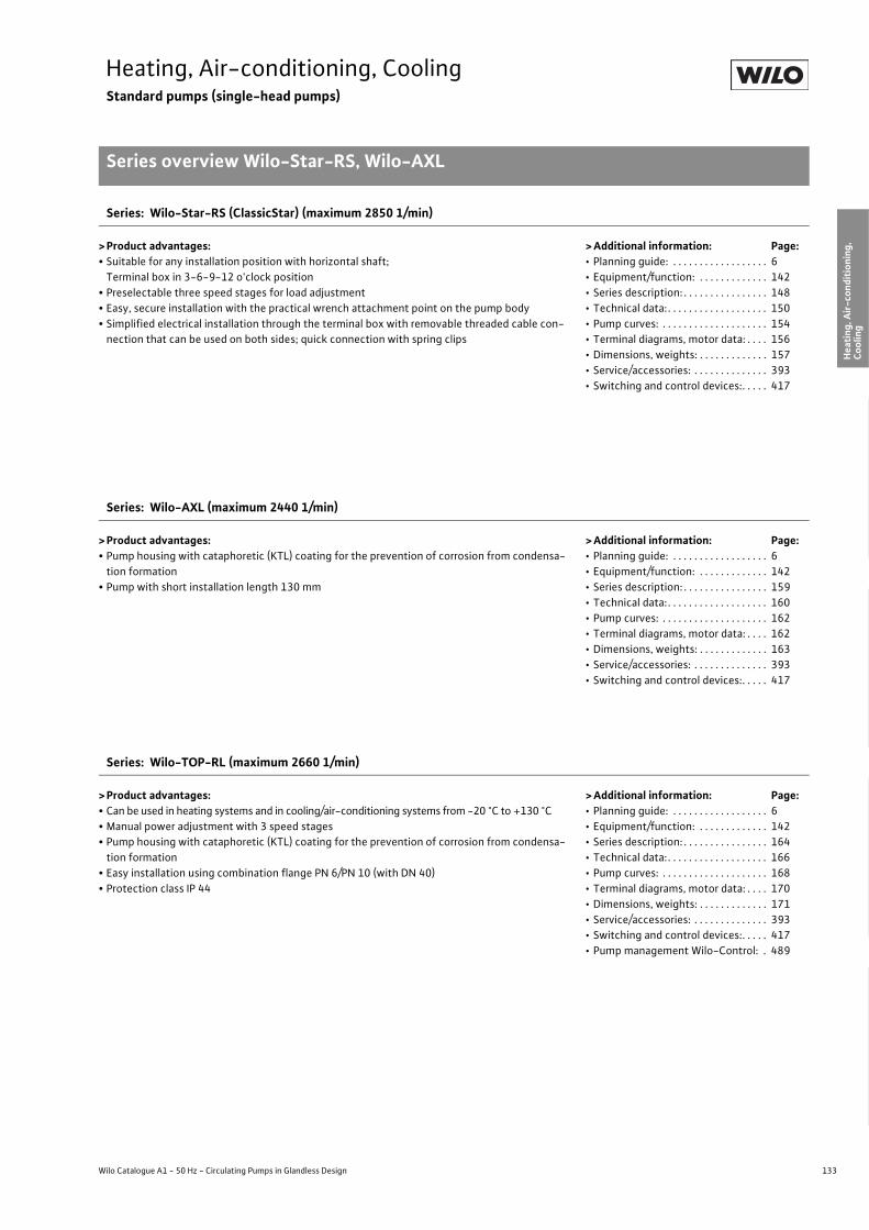
133
Heating, Air-conditioning, CoolingStandard pumps (single-head pumps)
Series overview Wilo-Star-RS, Wilo-AXL
Wilo Catalogue A1 - 50 Hz - Circulating Pumps in Glandless Design
Hea
ting,
Air-
cond
ition
ing,
Co
olin
gSe
cond
ary
Hot W
ater
Circ
ulat
ion
Sola
r The
rmal
, Geo
ther
mal
En
ergy
Sys
tem
sSe
rvic
e/Ac
cess
orie
s, S
yste
ms
Switc
hgea
rs a
nd C
ontr
ol
Dev
ices
Pum
p M
anag
emen
t Sys
tem
s
Series: Wilo-Star-RS (ClassicStar) (maximum 2850 1/min)
> Product advantages:• Suitable for any installation position with horizontal shaft;
Terminal box in 3-6-9-12 o'clock position• Preselectable three speed stages for load adjustment• Easy, secure installation with the practical wrench attachment point on the pump body• Simplified electrical installation through the terminal box with removable threaded cable con-
nection that can be used on both sides; quick connection with spring clips
> Additional information: Page:• Planning guide: . . . . . . . . . . . . . . . . . . 6• Equipment/function: . . . . . . . . . . . . . 142• Series description: . . . . . . . . . . . . . . . . 148• Technical data: . . . . . . . . . . . . . . . . . . . 150• Pump curves: . . . . . . . . . . . . . . . . . . . . 154• Terminal diagrams, motor data: . . . . 156• Dimensions, weights: . . . . . . . . . . . . . 157• Service/accessories: . . . . . . . . . . . . . . 393• Switching and control devices:. . . . . 417
Series: Wilo-AXL (maximum 2440 1/min)
> Product advantages:• Pump housing with cataphoretic (KTL) coating for the prevention of corrosion from condensa-
tion formation• Pump with short installation length 130 mm
> Additional information: Page:• Planning guide: . . . . . . . . . . . . . . . . . . 6• Equipment/function: . . . . . . . . . . . . . 142• Series description: . . . . . . . . . . . . . . . . 159• Technical data: . . . . . . . . . . . . . . . . . . . 160• Pump curves: . . . . . . . . . . . . . . . . . . . . 162• Terminal diagrams, motor data: . . . . 162• Dimensions, weights: . . . . . . . . . . . . . 163• Service/accessories: . . . . . . . . . . . . . . 393• Switching and control devices:. . . . . 417
Series: Wilo-TOP-RL (maximum 2660 1/min)
> Product advantages:• Can be used in heating systems and in cooling/air-conditioning systems from -20 °C to +130 °C• Manual power adjustment with 3 speed stages• Pump housing with cataphoretic (KTL) coating for the prevention of corrosion from condensa-
tion formation• Easy installation using combination flange PN 6/PN 10 (with DN 40)• Protection class IP 44
> Additional information: Page:• Planning guide: . . . . . . . . . . . . . . . . . . 6• Equipment/function: . . . . . . . . . . . . . 142• Series description: . . . . . . . . . . . . . . . . 164• Technical data: . . . . . . . . . . . . . . . . . . . 166• Pump curves: . . . . . . . . . . . . . . . . . . . . 168• Terminal diagrams, motor data: . . . . 170• Dimensions, weights: . . . . . . . . . . . . . 171• Service/accessories: . . . . . . . . . . . . . . 393• Switching and control devices:. . . . . 417• Pump management Wilo-Control: . 489

134 Subject to change without prior notice 09/2007 WILO AG
Heating, Air-conditioning, CoolingStandard pumps (single-head pumps)
Series overview Wilo-TOP-RL, Wilo-SE, Wilo-TOP-S
Series: Wilo-SE (maximum 2880 1/min)
>Single-head pumps:• Circulating pumps with screwed or flanged
connection>Application:• Hot-water heating systems for all systems,
industrial circulating systems, air-condi-tioning systems and closed cooling circuits
Series: Wilo-TOP-S (maximum 2850 1/min)
>Single-head pumps:• Circulating pumps with screwed or flanged
connection>Application:• Hot-water heating systems for all systems,
industrial circulating systems, air-condi-tioning systems and closed cooling circuits
Series: Wilo-TOP-D (maximum 1400 1/min)
>Single-head pumps:• Circulating pumps with screwed or flanged
connection>Application:• Hot-water heating systems for all systems,
industrial circulating systems, air-condi-tioning systems and closed cooling circuits
6
5
4
3
1
2
00 2 6 84 10 12 Q [m3/h]
H [
m]
Wilo-SE
SE 200
SE 125
SE 110, SE 150
Seriesexten
sion:
TOP-S25/13
Q[m³/h]
Wilo-TOP-S14
H[m]
12
10
8
6
4
2
00 10 20 30 40 50
50/15
65/13
50/10
40/10
65/1065/7
50/450/7
80/1080/765/15
100/10
30/10
40/7
25/1325/7
40/4
30/4
25/5
30/730/5
0
0,4
0,8
1,2
1,6
2,0
2,42,8
H[m
]
1 2 3 4 5 6 7 8910 20 30 40 Q[m³/h]
Wilo-TOP-D
D125
D100
D80
D65D50D40D30

135
Heating, Air-conditioning, CoolingStandard pumps (single-head pumps)
Series overview Wilo-TOP-RL, Wilo-SE, Wilo-TOP-S
Wilo Catalogue A1 - 50 Hz - Circulating Pumps in Glandless Design
Hea
ting,
Air-
cond
ition
ing,
Co
olin
gSe
cond
ary
Hot W
ater
Circ
ulat
ion
Sola
r The
rmal
, Geo
ther
mal
En
ergy
Sys
tem
sSe
rvic
e/Ac
cess
orie
s, S
yste
ms
Switc
hgea
rs a
nd C
ontr
ol
Dev
ices
Pum
p M
anag
emen
t Sys
tem
s
Series: Wilo-SE (maximum 2880 1/min)
> Product advantages:• Can be used in heating systems and in cooling/air-conditioning systems from -20 °C to +130 °C• Manual power adjustment with 3 speed stages.• Pump housing with cataphoretic (KTL) coating for the prevention of corrosion from condensa-
tion formation• Easy installation using combination flange PN 6/PN 10 (with DN 40)• With kit including seal for length compensation between the connection adapters from
244 mm to 250 mm. Equipped as standard for all pump types with flange connection• Protection class IP 44
> Additional information: Page:• Planning guide: . . . . . . . . . . . . . . . . . . 6• Equipment/function: . . . . . . . . . . . . . 142• Series description: . . . . . . . . . . . . . . . . 172• Technical data: . . . . . . . . . . . . . . . . . . . 174• Pump curves: . . . . . . . . . . . . . . . . . . . . 176• Terminal diagrams, motor data: . . . . 177• Dimensions, weights: . . . . . . . . . . . . . 178• Service/accessories: . . . . . . . . . . . . . . 393• Switching and control devices:. . . . . 417• Pump management Wilo-Control: . 489
Series: Wilo-TOP-S (maximum 2850 1/min)
> Product advantages:• Can be used in heating systems and in cooling/air-conditioning systems from -20 °C to +130 °C• Manual power adjustment with 2 speed stages (for pumps 1~230 V with P2 � 350 W) or with
3 speed stages• Pump housing with cataphoretic (KTL) coating for the prevention of corrosion from condensa-
tion formation• With thermal insulation as standard• Easy installation using combination flange PN 6/PN 10 (for DN 40 - DN 65)• Cable feed to terminal box possible on both sides (starting with P1 � 250 W) with integrated
strain-relief device• Protection class IP 44
> Additional information: Page:• Planning guide: . . . . . . . . . . . . . . . . . . 6• Equipment/function: . . . . . . . . . . . . . 145• Series description: . . . . . . . . . . . . . . . . 180• Technical data: . . . . . . . . . . . . . . . . . . . 182• Pump curves: . . . . . . . . . . . . . . . . . . . . 188• Terminal diagrams: . . . . . . . . . . . . . . . 197• Motor data: . . . . . . . . . . . . . . . . . . . . . . 198• Dimensions, weights: . . . . . . . . . . . . . 201• Service/accessories: . . . . . . . . . . . . . . 393• Switching and control devices:. . . . . 417• Pump management Wilo-Control: . 489
Series: Wilo-TOP-D (maximum 1400 1/min)
> Product advantages:• For installations with low pipework resistances, can be utilised in heating systems and in cool-
ing/air-conditioning systems from -20 °C to +130 °C• Universal utilisation for various mains operations, 3~400 V as standard connection, 3~230 V
with modification of the terminal allocation and 1~230 V with the use of a capacitor (accesso-ries)
• Pump housing with cataphoretic (KTL) coating for the prevention of corrosion from condensa-tion formation
• With thermal insulation as standard• Easy installation using combination flange PN 6/PN 10 (for DN 40 - DN 65)• Cable feed to terminal box possible on both sides (starting with P1 = 95 W) possible with inte-
grated strain-relief device• Protection class IP 44
> Additional information: Page:• Planning guide: . . . . . . . . . . . . . . . . . . 6• Equipment/function: . . . . . . . . . . . . . 145• Series description: . . . . . . . . . . . . . . . . 204• Technical data: . . . . . . . . . . . . . . . . . . . 206• Pump curves: . . . . . . . . . . . . . . . . . . . . 208• Terminal diagrams: . . . . . . . . . . . . . . . 210• Motor data . . . . . . . . . . . . . . . . . . . . . . 211• Dimensions, weights: . . . . . . . . . . . . . 212• Service/accessories: . . . . . . . . . . . . . . 393• Switching and control devices:. . . . . 417• Pump management Wilo-Control: . 489

136 Subject to change without prior notice 09/2007 WILO AG
Heating, Air-conditioning, CoolingStandard pumps (single-head pumps)
Series overview Wilo-TOP-D, Wilo-RP, Wilo-P
Series: Wilo-RP (maximum 1400 1/min)
>Single-head pumps:• Circulating pumps with screwed connection>Application:• Hot-water heating systems for all systems,
industrial circulation systems
Series: Wilo-P (maximum 1400 1/min)
>Single-head pumps:• Circulating pumps with flanged connection>Application:• Hot-water heating systems for all systems,
industrial circulation systems
0 1 2 3 4 5 Q[m³/h]0
1
2
3
RP 25/80r, RP 30/80r
RP 25/100r, RP 30/100r
Wilo-RP
H[m
]
0 2 4 6 8 10 15 20 25 30 35 40 45 50 60 70 Q[m3/h]0
1
10
23456789
12 P 50/250 r P 65/250 r
P 100/200 r
P 80/250 r
P 100/160 r
P 80/160 r
P 65/160 r P 50/160 r P 80/125 r P65/ 125r
P 50/125 r
P 40/160 r
P 40/100 r
Wilo-P [m
]H

137
Heating, Air-conditioning, CoolingStandard pumps (single-head pumps)
Series overview Wilo-TOP-D, Wilo-RP, Wilo-P
Wilo Catalogue A1 - 50 Hz - Circulating Pumps in Glandless Design
Hea
ting,
Air-
cond
ition
ing,
Co
olin
gSe
cond
ary
Hot W
ater
Circ
ulat
ion
Sola
r The
rmal
, Geo
ther
mal
En
ergy
Sys
tem
sSe
rvic
e/Ac
cess
orie
s, S
yste
ms
Switc
hgea
rs a
nd C
ontr
ol
Dev
ices
Pum
p M
anag
emen
t Sys
tem
s
Series: Wilo-RP
> Product advantages:• Manual power adjustment with 4 speed stages.• Pump housing with cataphoretic (KTL) coating for the prevention of corrosion from condensa-
tion formation
>Additional information: Page:• Planning guide:. . . . . . . . . . . . . . . . . . . 6• Equipment/function:. . . . . . . . . . . . . . 145• Series description: . . . . . . . . . . . . . . . . 214• Technical data: . . . . . . . . . . . . . . . . . . . 216• Pump curves: . . . . . . . . . . . . . . . . . . . . 218• Terminal diagrams: . . . . . . . . . . . . . . . 219• Motor data: . . . . . . . . . . . . . . . . . . . . . . 220• Dimensions, weights: . . . . . . . . . . . . . 221• Service/accessories: . . . . . . . . . . . . . . 393• Switching and control devices:. . . . . 417
Series: Wilo-P
> Product advantages:• Manual power adjustment with 4 speed stages.• Pump housing with cataphoretic (KTL) coating for the prevention of corrosion from condensa-
tion formation
>Additional information: Page:• Planning guide:. . . . . . . . . . . . . . . . . . . 6• Equipment/function:. . . . . . . . . . . . . . 145• Series description: . . . . . . . . . . . . . . . . 222• Technical data: . . . . . . . . . . . . . . . . . . . 224• Pump curves: . . . . . . . . . . . . . . . . . . . . 226• Terminal diagrams, motor data: . . . . 230• Dimensions, weights: . . . . . . . . . . . . . 232• Service/accessories: . . . . . . . . . . . . . . 393• Switching and control devices:. . . . . 417

138 Subject to change without prior notice 09/2007 WILO AG
Heating, Air-conditioning, CoolingStandard pumps (twin-head pumps)
Series overview Wilo-Star-RSD, Wilo-TOP-SD, SE-TW
Series: Wilo-Star-RSD (ClassicStar)
>Twin-head pumps:• Multi-speed circulating pumps with
screwed connection>Application:• Hot-water heating systems for all systems,
industrial circulating systems, cold water systems and air-conditioning systems
Series: Wilo-TOP-SD (maximum 2850 1/min)
>Twin-head pumps:• Circulating pumps with screwed or flanged
connection>Application:• Hot-water heating systems for all systems,
industrial circulating systems, air-condi-tioning systems and closed cooling circuits
Series: Wilo-SE-TW (maximum 2880 1/min)
>Twin-head pumps:• Circulating pumps with screwed or flanged
connection>Application:• Hot-water heating systems for all systems,
industrial circulating systems, air-condi-tioning systems and closed cooling circuits
0 1 2 3 4 5 60
1
2
3
4 Star-RSD 30/6Star-RSD 30/4
Wilo-ClassicStar
Q[m3/h]
H[m
]
+
Seriesexten
sion:
TOP-SD 32/1
0 0 10 20 30 40 50 60 70 80 90
0
2
4
6
8
10
12
80/10
40/7
50/7
32/7
65/10
65/13
65/15
40/3
30/5
Q[m³/h]
H[m
]
+40/15
50/15
Wilo-TOP-SD
50/10
32/10
40/10
6
5
4
3
1
2
00 2 6 84 10 12 14 16 Q [m3/h]
H [m
]
Wilo-SE-TW
SE 200-N-TW
SE 150-N-TW
SE 125-N-TW
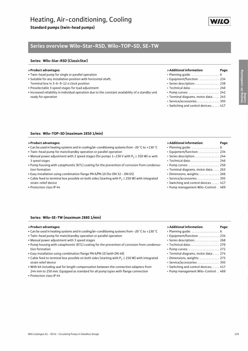
139
Heating, Air-conditioning, CoolingStandard pumps (twin-head pumps)
Series overview Wilo-Star-RSD, Wilo-TOP-SD, SE-TW
Wilo Catalogue A1 - 50 Hz - Circulating Pumps in Glandless Design
Hea
ting,
Air-
cond
ition
ing,
Co
olin
gSe
cond
ary
Hot W
ater
Circ
ulat
ion
Sola
r The
rmal
, Geo
ther
mal
En
ergy
Sys
tem
sSe
rvic
e/Ac
cess
orie
s, S
yste
ms
Switc
hgea
rs a
nd C
ontr
ol
Dev
ices
Pum
p M
anag
emen
t Sys
tem
s
Series: Wilo-Star-RSD (ClassicStar)
> Product advantages:• Twin-head pump for single or parallel operation• Suitable for any installation position with horizontal shaft;
Terminal box in 3-6-9-12 o'clock position• Preselectable 3 speed stages for load adjustment• Increased reliability in individual operation due to the constant availability of a standby unit
ready for operation
> Additional information: Page:• Planning guide: . . . . . . . . . . . . . . . . . . 6• Equipment/function: . . . . . . . . . . . . . 234• Series description: . . . . . . . . . . . . . . . . 238• Technical data: . . . . . . . . . . . . . . . . . . . 240• Pump curves: . . . . . . . . . . . . . . . . . . . . 242• Terminal diagrams, motor data: . . . . 243• Service/accessories: . . . . . . . . . . . . . . 393• Switching and control devices:. . . . . 417
Series: Wilo-TOP-SD (maximum 2850 1/min)
> Product advantages:• Can be used in heating systems and in cooling/air-conditioning systems from -20 °C to +130 °C• Twin-head pump for main/standby operation or parallel operation• Manual power adjustment with 2 speed stages (for pumps 1~230 V with P2 � 350 W) or with
3 speed stages• Pump housing with cataphoretic (KTL) coating for the prevention of corrosion from condensa-
tion formation• Easy installation using combination flange PN 6/PN 10 (for DN 32 - DN 65)• Cable feed to terminal box possible on both sides (starting with P1 � 250 W) with integrated
strain-relief device• Protection class IP 44
> Additional information: Page:• Planning guide: . . . . . . . . . . . . . . . . . . 6• Equipment/function: . . . . . . . . . . . . . 234• Series description: . . . . . . . . . . . . . . . . 244• Technical data: . . . . . . . . . . . . . . . . . . . 246• Pump curves: . . . . . . . . . . . . . . . . . . . . 250• Terminal diagrams, motor data: . . . . 263• Dimensions, weights: . . . . . . . . . . . . . 266• Service/accessories: . . . . . . . . . . . . . . 393• Switching and control devices . . . . . 417• Pump management Wilo-Control: . 489
Series: Wilo-SE-TW (maximum 2880 1/min)
> Product advantages:• Can be used in heating systems and in cooling/air-conditioning systems from -20 °C to +130 °C• Twin-head pump for main/standby operation or parallel operation• Manual power adjustment with 3 speed stages• Pump housing with cataphoretic (KTL) coating for the prevention of corrosion from condensa-
tion formation• Easy installation using combination flange PN 6/PN 10 (with DN 40)• Cable feed to terminal box possible on both sides (starting with P1 � 250 W) with integrated
strain relief device• With kit including seal for length compensation between the connection adapters from
244 mm to 250 mm. Equipped as standard for all pump types with flange connection• Protection class IP 44
> Additional information: Page:• Planning guide: . . . . . . . . . . . . . . . . . . 6• Equipment/function: . . . . . . . . . . . . . 234• Series description: . . . . . . . . . . . . . . . . 268• Technical data: . . . . . . . . . . . . . . . . . . . 270• Pump curves: . . . . . . . . . . . . . . . . . . . . 272• Terminal diagrams, motor data: . . . . 274• Dimensions, weights: . . . . . . . . . . . . . 275• Service/accessories: . . . . . . . . . . . . . . 393• Switching and control devices:. . . . . 417• Pump management Wilo-Control: . 489
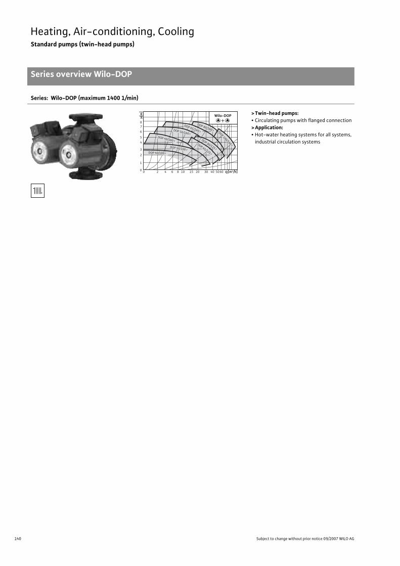
140 Subject to change without prior notice 09/2007 WILO AG
Heating, Air-conditioning, CoolingStandard pumps (twin-head pumps)
Series overview Wilo-DOP
Series: Wilo-DOP (maximum 1400 1/min)
>Twin-head pumps:• Circulating pumps with flanged connection>Application:• Hot-water heating systems for all systems,
industrial circulation systems
0 2 4 6 8 10 15 20 30 40 5060 Q[m3/h]0
1
2
3
4
5
6
78
[m
]H
DOP 80/160 r
DOP 65/160 r DOP 100/160 r
DOP 80/125 r
DOP 65/125 r
DOP 50/160 r DOP 40/160 r
DOP 50/100 r DOP 40/100 r
Wilo-DOP+
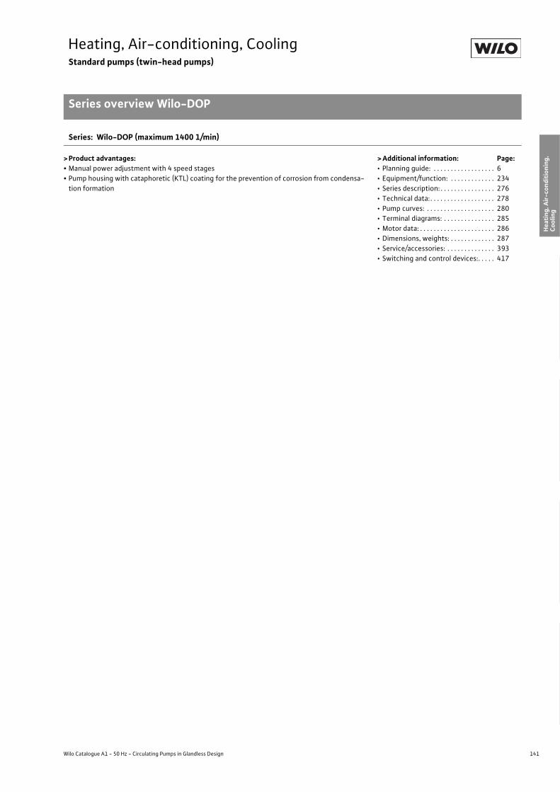
141
Heating, Air-conditioning, CoolingStandard pumps (twin-head pumps)
Series overview Wilo-DOP
Wilo Catalogue A1 - 50 Hz - Circulating Pumps in Glandless Design
Hea
ting,
Air-
cond
ition
ing,
Co
olin
gSe
cond
ary
Hot W
ater
Circ
ulat
ion
Sola
r The
rmal
, Geo
ther
mal
En
ergy
Sys
tem
sSe
rvic
e/Ac
cess
orie
s, S
yste
ms
Switc
hgea
rs a
nd C
ontr
ol
Dev
ices
Pum
p M
anag
emen
t Sys
tem
s
Series: Wilo-DOP (maximum 1400 1/min)
> Product advantages:• Manual power adjustment with 4 speed stages• Pump housing with cataphoretic (KTL) coating for the prevention of corrosion from condensa-
tion formation
> Additional information: Page:• Planning guide: . . . . . . . . . . . . . . . . . . 6• Equipment/function: . . . . . . . . . . . . . 234• Series description: . . . . . . . . . . . . . . . . 276• Technical data: . . . . . . . . . . . . . . . . . . . 278• Pump curves: . . . . . . . . . . . . . . . . . . . . 280• Terminal diagrams: . . . . . . . . . . . . . . . 285• Motor data: . . . . . . . . . . . . . . . . . . . . . . 286• Dimensions, weights: . . . . . . . . . . . . . 287• Service/accessories: . . . . . . . . . . . . . . 393• Switching and control devices:. . . . . 417

142 Subject to change without prior notice 09/2007 WILO AG
Heating, Air-conditioning, CoolingStandard pumps (single-head pumps)
Equipment/function Wilo-Star-RS, AXL, TOP-RL, SE
Wilo-Star-RS (ClassicStar) Wilo-AXL Wilo-TOP-RL Wilo-SE
(maximum 2850 1/min)
(maximum 2440 1/min)
(maximum 2660 1/min)
(maximum 2880 1/min)
Operating mode
Speed-stage switching • • • •Manual control mode (n=constant) – – – –
�p-c for constant differential pressure – – – –
�p-v for variable differential pressure – – – –
�p-T for temperature-prompted differential pressure – – – –
Manual functions
Setting the operating mode – – – –
Setting the differential-pressure setpoint – – – –
Setting to “Autopilot” (automatic setback operation) – – – –
Setting the pump to ON/OFF – – – –
Setting the speed (manual setting mode) – – – –
Setting the speed stages 3 2 3 3
Automatic functions
Stageless power adjustment depending on the oper-ating mode – – – –
“Autopilot” automatic setback operation – – – –
Deblocking function – – – –
Soft start – – – –
Safety control – – – –
Full motor protection with integrated trip electronics
– – •(optional for all types with Wilo-Protect-
Module C)
•(optional for all types with Wilo-Protect-
Module C)
External control functions
Control input “Overriding Off”
– – •(optional for all types with Wilo-Protect-
Module C)
•(optional for all types with Wilo-Protect-
Module C)
Control input “Overriding Min” – – – –
Control input “Analogue In 0 - 10 V” (remote speed adjustment) – – – –
Control input “Analogue In 0 - 10 V” (remote setpoint adjustment) – – – –
Signal and display functions
Single/collective fault signal (potential-free NC contact)
– – •(optional for all types with Wilo-Protect-
Module C)
•(optional for all types with Wilo-Protect-
Module C)
• = available, – = not available

143
Heating, Air-conditioning, CoolingStandard pumps (single-head pumps)
Equipment/function Wilo-Star-RS, AXL, TOP-RL, SE
Wilo Catalogue A1 - 50 Hz - Circulating Pumps in Glandless Design
Hea
ting,
Air-
cond
ition
ing,
Co
olin
gSe
cond
ary
Hot W
ater
Circ
ulat
ion
Sola
r The
rmal
, Geo
ther
mal
En
ergy
Sys
tem
sSe
rvic
e/Ac
cess
orie
s, S
yste
ms
Switc
hgea
rs a
nd C
ontr
ol
Dev
ices
Pum
p M
anag
emen
t Sys
tem
s
Signal and display functions (continued)
Collective fault signal (potential-free NC contact)
– – •(optional for all types with Wilo-Protect-
Module C)
•(optional for all types with Wilo-Protect-
Module C)
Individual run signal (potential-free NO contact)
– – •(optional for all types
with WiloProtect Module C)
•(optional for all types with Wilo-Protect-
Module C)
Thermal winding contact (WSK, potential-free NC contact) – – – –
Fault signal light
– – •(optional for all types with Wilo-Protect-
Module C)
•(optional for all types with Wilo-Protect-
Module C)
Direction-of-rotation control lamp – – – –
LC display for showing pump data and fault codes – – – –
Data exchange
Infrared interface for wireless data exchange with IR-Module/ IR-Monitor (see IR-Module/IR-Monitor Function table)
– – – –
Serial digital PLR interface for connection to BA building automation via Wilo interface converter or company-specific coupling module
– – – –
Serial digital LON interface for connection toa LONWorks network – – – –
Serial digital CAN interface for connection to a CAN bus system – – – –
Dual pump management (twin-head pump or 2 x single-head pumps)
Main/standby operation (automatic fault-actuated switchover/time-sensitive pump alteration)
– – •(optional for all types with Wilo-Protect-
Module C)
•(optional for all types with Wilo-Protect-
Module C)
Parallel operation (efficiency-optimised peak-load cut-in and out) – – – –
Equipment/scope of delivery
Wrench attachment point on pump body • – – –
Double switchover valve in pump housing – – – –
Cable entry possible on both sides • – – –
Quick connection with spring clips • – – –
Integrated air extraction fitting for automatic rapid ventilator Rp 3/8
•(only as RSL version)
– – –
Plug-in slot for optional expansion with Wilo-IF-Modules – – – –
Wilo-Star-RS (ClassicStar) Wilo-AXL Wilo-TOP-RL Wilo-SE
(maximum 2850 1/min)
(maximum 2440 1/min)
(maximum 2660 1/min)
(maximum 2880 1/min)
• = available, – = not available

144 Subject to change without prior notice 09/2007 WILO AG
Heating, Air-conditioning, CoolingStandard pumps (single-head pumps)
Equipment/function Wilo-Star-RS, AXL, TOP-RL, SE
Equipment/scope of delivery (continued)
Blocking current-proof motor • – – –
Including seals for threaded connection (loose) • – • •Including installation and operating instructions • • • •Including thermal insulation – – – –
Including washers for flange bolts – – –•
(for nominal connec-tion width DN 40)
Incl. 1.8 m power cable with grounding plug – – – –
Integrated non-return valve – – – –
Integrated ball shutoff valve – – – –
Including clock timer – – – –
Particle filter – – – –
Wilo-Star-RS (ClassicStar) Wilo-AXL Wilo-TOP-RL Wilo-SE
(maximum 2850 1/min)
(maximum 2440 1/min)
(maximum 2660 1/min)
(maximum 2880 1/min)
• = available, – = not available
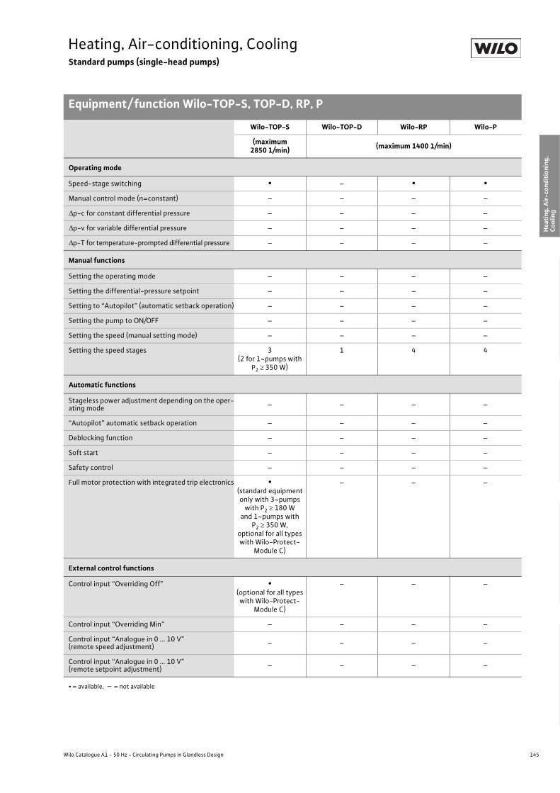
145
Heating, Air-conditioning, CoolingStandard pumps (single-head pumps)
Equipment/ function Wilo-TOP-S, TOP-D, RP, P
Wilo Catalogue A1 - 50 Hz - Circulating Pumps in Glandless Design
Hea
ting,
Air-
cond
ition
ing,
Co
olin
gSe
cond
ary
Hot W
ater
Circ
ulat
ion
Sola
r The
rmal
, Geo
ther
mal
En
ergy
Sys
tem
sSe
rvic
e/Ac
cess
orie
s, S
yste
ms
Switc
hgea
rs a
nd C
ontr
ol
Dev
ices
Pum
p M
anag
emen
t Sys
tem
s
Wilo-TOP-S Wilo-TOP-D Wilo-RP Wilo-P
(maximum 2850 1/min) (maximum 1400 1/min)
Operating mode
Speed-stage switching • – • •Manual control mode (n=constant) – – – –
�p-c for constant differential pressure – – – –
�p-v for variable differential pressure – – – –
�p-T for temperature-prompted differential pressure – – – –
Manual functions
Setting the operating mode – – – –
Setting the differential-pressure setpoint – – – –
Setting to “Autopilot” (automatic setback operation) – – – –
Setting the pump to ON/OFF – – – –
Setting the speed (manual setting mode) – – – –
Setting the speed stages 3(2 for 1~pumps with
P2 � 350 W)
1 4 4
Automatic functions
Stageless power adjustment depending on the oper-ating mode – – – –
“Autopilot” automatic setback operation – – – –
Deblocking function – – – –
Soft start – – – –
Safety control – – – –
Full motor protection with integrated trip electronics •(standard equipment only with 3~pumps
with P2 � 180 W and 1~pumps with
P2 � 350 W,optional for all types with Wilo-Protect-
Module C)
– – –
External control functions
Control input “Overriding Off” •(optional for all types with Wilo-Protect-
Module C)
– – –
Control input “Overriding Min” – – – –
Control input “Analogue in 0 ... 10 V” (remote speed adjustment) – – – –
Control input “Analogue in 0 ... 10 V” (remote setpoint adjustment) – – – –
• = available, – = not available
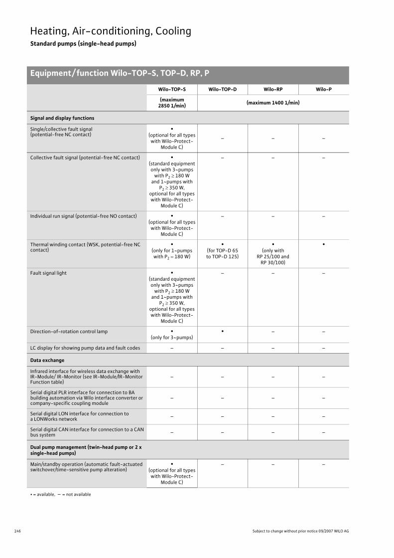
146 Subject to change without prior notice 09/2007 WILO AG
Heating, Air-conditioning, CoolingStandard pumps (single-head pumps)
Equipment/ function Wilo-TOP-S, TOP-D, RP, P
Signal and display functions
Single/collective fault signal (potential-free NC contact)
•(optional for all types with Wilo-Protect-
Module C)
– – –
Collective fault signal (potential-free NC contact) •(standard equipment only with 3~pumps
with P2 � 180 W and 1~pumps with
P2 � 350 W,optional for all types with Wilo-Protect-
Module C)
– – –
Individual run signal (potential-free NO contact) •(optional for all types with Wilo-Protect-
Module C)
– – –
Thermal winding contact (WSK, potential-free NC contact)
•(only for 1~pumps with P2 180 W)
•(for TOP-D 65to TOP-D 125)
•(only with
RP 25/100 andRP 30/100)
•
Fault signal light •(standard equipment only with 3~pumps
with P2 � 180 W and 1~pumps with
P2 � 350 W,optional for all types with Wilo-Protect-
Module C)
– – –
Direction-of-rotation control lamp •(only for 3~pumps)
• – –
LC display for showing pump data and fault codes – – – –
Data exchange
Infrared interface for wireless data exchange with IR-Module/ IR-Monitor (see IR-Module/IR-Monitor Function table)
– – – –
Serial digital PLR interface for connection to BA building automation via Wilo interface converter or company-specific coupling module
– – – –
Serial digital LON interface for connection to a LONWorks network – – – –
Serial digital CAN interface for connection to a CAN bus system – – – –
Dual pump management (twin-head pump or 2 x single-head pumps)
Main/standby operation (automatic fault-actuated switchover/time-sensitive pump alteration)
•(optional for all types with Wilo-Protect-
Module C)
– – –
Wilo-TOP-S Wilo-TOP-D Wilo-RP Wilo-P
(maximum 2850 1/min) (maximum 1400 1/min)
• = available, – = not available

147
Heating, Air-conditioning, CoolingStandard pumps (single-head pumps)
Equipment/ function Wilo-TOP-S, TOP-D, RP, P
Wilo Catalogue A1 - 50 Hz - Circulating Pumps in Glandless Design
Hea
ting,
Air-
cond
ition
ing,
Co
olin
gSe
cond
ary
Hot W
ater
Circ
ulat
ion
Sola
r The
rmal
, Geo
ther
mal
En
ergy
Sys
tem
sSe
rvic
e/Ac
cess
orie
s, S
yste
ms
Switc
hgea
rs a
nd C
ontr
ol
Dev
ices
Pum
p M
anag
emen
t Sys
tem
s
Parallel operation (efficiency-optimised peak-load cut-in and out) – – – –
Equipment/scope of delivery
Wrench attachment point on pump body – – – –
Double switchover valve in pump housing – – – –
Cable entry possible on both sides •(only with 1~pumps and 3~pumps with
P2 � 180 W)
•(for TOP-D 65to TOP-D 125)
– –
Quick connection with spring clips – – – –
Integrated air extraction fitting for automatic rapid ventilator Rp 3/8
– – – –
Plug-in slot for optional expansion with Wilo-IF-Modules – – – –
Blocking current-proof motor – •(only with TOP-D
30, 40, 50)
•(not with RP 25/100
and RP 30/100)
–
Including seals for threaded connection (loose) • • • –
Including installation and operating instructions • • • •Including thermal insulation • • – –
Including washers for flange bolts(for nominal connection widths DN 32 - DN 65) • • – –
Incl. 1.8 m power cable with grounding plug – – – –
Integrated non-return valve – – – –
Integrated ball shutoff valve – – – –
Including clock timer – – – –
Wilo-TOP-S Wilo-TOP-D Wilo-RP Wilo-P
(maximum 2850 1/min) (maximum 1400 1/min)
• = available, – = not available

148 Subject to change without prior notice 09/2007 WILO AG
Heating, Air-conditioning, CoolingStandard pumps (single-head pumps)
Series description Wilo-Star-RS (ClassicStar)
Wilo-Star-RS (ClassicStar)
ConstructionGlandless circulating pump with screwed connection. Preselectable speed stages for power adjustment
ApplicationHot-water heating systems for all systems, industrial circulating sys-tems, cold water systems and air-conditioning systems
Type keyExample: Wilo-Star-RS 25/4Star-RS Standard pump (screw-end pump)25/ Nominal connection width R4 Nominal delivery head [m] when Q = 0 m3/h
Options• Version ...RG with housing made of red brass• Version ...-130 with short over-all length 130 mm • RSL version with connection for rapid ventilation.
Special features/product advantages• Suitable for any installation position with horizontal shaft; Terminal
box in 3-6-9-12 o'clock position• Preselectable three speed stages for load adjustment• Easy, secure installation with the practical wrench attachment point
on the pump body• Simplified electrical installation through the terminal box with
removable threaded cable connection that can be used on both sides; Quick connection with spring clips
ATTENTION:For EEI classification for each pump model see Chapter “Planning guide”, Table on page 20.
0
1
2
3
4
5
6
7
H[m]
0 1 2 3 4 5 Q [m³/h]
Star-RS 15/6, 25/6, 30/6
Star-RS 15/8, 25/8, 30/8
Star-RS 15/4, 25/4, 30/4
Star-RS 15/7, 25/7, 30/7
Star-RS 25/2, 30/2
Wilo-Star-RS

149
Heating, Air-conditioning, CoolingStandard pumps (single-head pumps)
Series description Wilo-Star-RS (ClassicStar)
Wilo Catalogue A1 - 50 Hz - Circulating Pumps in Glandless Design
Hea
ting,
Air-
cond
ition
ing,
Co
olin
gSe
cond
ary
Hot W
ater
Circ
ulat
ion
Sola
r The
rmal
, Geo
ther
mal
En
ergy
Sys
tem
sSe
rvic
e/Ac
cess
orie
s, S
yste
ms
Switc
hgea
rs a
nd C
ontr
ol
Dev
ices
Pum
p M
anag
emen
t Sys
tem
s
Equipment/function
Operating modes• Speed-stage switching
Manual functions• Selection of speed stages (3 speed stages)
Equipment/scope of delivery• Wrench attachment point on pump body• Cable entry possible on both sides• Quick connection with spring clips• Integrated air extraction fitting for automatic quick aspirator Rp 3/8
(only version ...-RSL)• Blocking current-proof motor• Including seals for threaded connection (loose)• Including installation and operating instructions
Accessories• Screwed connections• Thermal insulation shells

150 Subject to change without prior notice 09/2007 WILO AG
Heating, Air-conditioning, CoolingStandard pumps (single-head pumps)
Technical data Wilo-Star-RS
Wilo-Star-RS...(ClassicStar)
15/4 15/6 25/2 25/4 25/6 25/7
Approved fluids(other fluids on request)
Heating water (as per VDI 2035) • • • • • •Water/glycol mixtures (maximum 1:1; mixtures with more than 20% glycol content require rechecking of the pumping data)
• • • • • •
Secondary hot water and water for food businesses as per TrinkwV 2001 – – – – – –
Performance
Maximum delivery head [m] 4.0 6.0 2.0 4.0 6.0 7.0
Maximum flow volume [m3/h] 3.5 4.0 2.5 3.5 4.0 5.5
Permitted field of application
Temperature range for utilisation in HVAC systemswith maximum ambient temperature +25°C [°C]with maximum ambient temperature +40°C [°C]
–-10 up to +110
Temperature range for utilisation in secondary hot water circulation systems
at maximum ambient temperature +40 °C [°C] – – – – – –
Maximum permissible total hardness in secondary hot water-circulation systems [°d] – – – – – –
Standard version for operating pressure pmax [bar] 10 10 10 10 10 10
Special version for operating pressure pmax [bar] – – – – – –
Pipe connections
Screwed connection Rp 1/21/2 1 1 1 1
Nominal connection diameter flange DN – – – – – –
Flange for counter flange PN 6, standard version – – – – – –
Counter flange for PN 16, flange, special version – – – – – –
Combination flange PN 6/10 for counter flange PN 6 and PN 16, standard version – – – – – –
Support-bracket mounting (with horizontal shaft only), standard version – – – – – –
Support-bracket mounting (with horizontal shaft only), special version – – – – – –
Electrical connection
Mains connection 1~ [V], standard version 230 230 230 230 230 230
Mains connection 3~ [V], standard version – – – – – –
Mains connection 3~ [V], with optional switching plug – – – – – –
Mains frequency [Hz] 50 50 50 50 50 50
• = available, – = not available

151
Heating, Air-conditioning, CoolingStandard pumps (single-head pumps)
Technical data Wilo-Star-RS
Wilo Catalogue A1 - 50 Hz - Circulating Pumps in Glandless Design
Hea
ting,
Air-
cond
ition
ing,
Co
olin
gSe
cond
ary
Hot W
ater
Circ
ulat
ion
Sola
r The
rmal
, Geo
ther
mal
En
ergy
Sys
tem
sSe
rvic
e/Ac
cess
orie
s, S
yste
ms
Switc
hgea
rs a
nd C
ontr
ol
Dev
ices
Pum
p M
anag
emen
t Sys
tem
s
Motor/electronics
Electromagnetic compatibility – – – – – –
Emitted interference EN 61000-6-3
Immunity to interference EN 61000-6-2
Power electronics – – – – – –
Protection class IP 44 IP 44 IP 44 IP 44 IP 44 IP 44
Insulation class F F F F F F
Materials
Pump housing Cast iron (EN-GJL-200)
Impeller Plastic (PP - 40% GF)
Shaft Stainless steel (X46 Cr13)
Bearing Metal-impregnated carbon
Minimum suction head at suction port [m]for the prevention of cavitation at water delivery temperature
50 °C 0.5 0.5 0.5 0.5 0.5 0.5
95 °C 3 3 3 3 3 3
110 °C 10 10 10 10 10 10
130 °C – – – – – –
Wilo-Star-RS...(ClassicStar)
15/4 15/6 25/2 25/4 25/6 25/7
• = available, – = not available
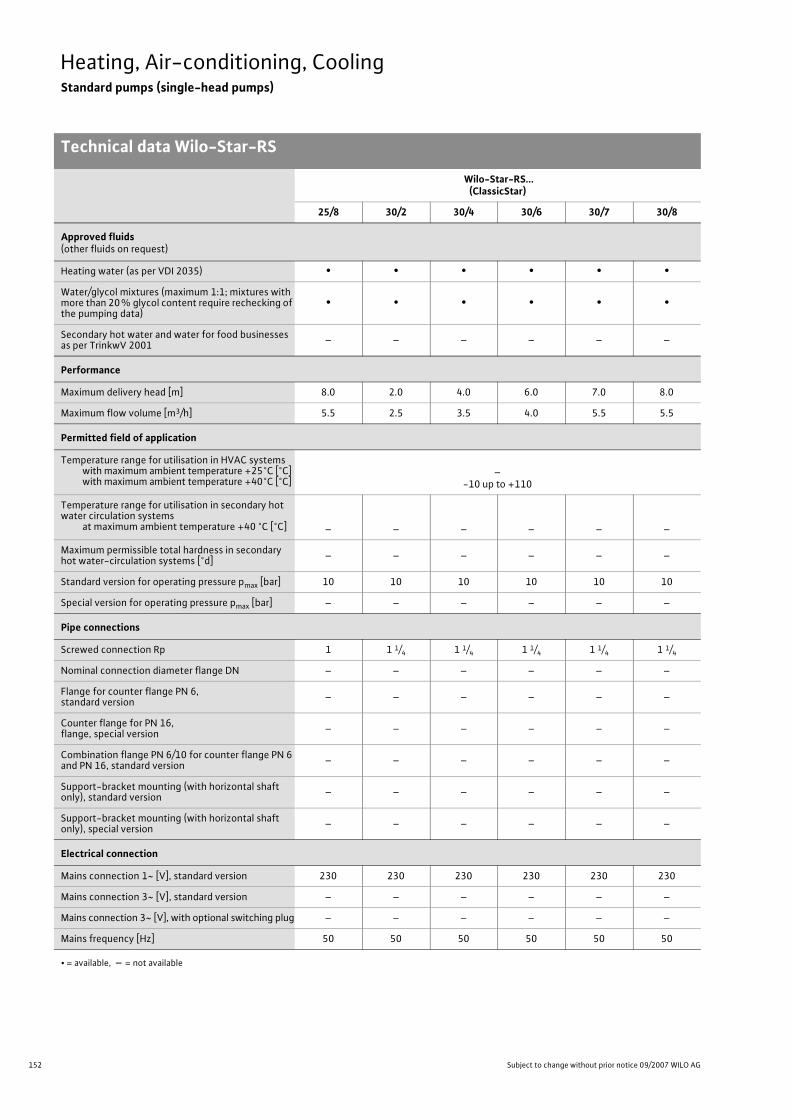
152 Subject to change without prior notice 09/2007 WILO AG
Heating, Air-conditioning, CoolingStandard pumps (single-head pumps)
Technical data Wilo-Star-RS
Wilo-Star-RS...(ClassicStar)
25/8 30/2 30/4 30/6 30/7 30/8
Approved fluids(other fluids on request)
Heating water (as per VDI 2035) • • • • • •Water/glycol mixtures (maximum 1:1; mixtures with more than 20% glycol content require rechecking of the pumping data)
• • • • • •
Secondary hot water and water for food businesses as per TrinkwV 2001 – – – – – –
Performance
Maximum delivery head [m] 8.0 2.0 4.0 6.0 7.0 8.0
Maximum flow volume [m3/h] 5.5 2.5 3.5 4.0 5.5 5.5
Permitted field of application
Temperature range for utilisation in HVAC systemswith maximum ambient temperature +25°C [°C]with maximum ambient temperature +40°C [°C]
–-10 up to +110
Temperature range for utilisation in secondary hot water circulation systems
at maximum ambient temperature +40 °C [°C] – – – – – –
Maximum permissible total hardness in secondary hot water-circulation systems [°d] – – – – – –
Standard version for operating pressure pmax [bar] 10 10 10 10 10 10
Special version for operating pressure pmax [bar] – – – – – –
Pipe connections
Screwed connection Rp 1 1 1/4 1 1/4 1 1/4 1 1/4 1 1/4
Nominal connection diameter flange DN – – – – – –
Flange for counter flange PN 6, standard version – – – – – –
Counter flange for PN 16, flange, special version – – – – – –
Combination flange PN 6/10 for counter flange PN 6 and PN 16, standard version – – – – – –
Support-bracket mounting (with horizontal shaft only), standard version – – – – – –
Support-bracket mounting (with horizontal shaft only), special version – – – – – –
Electrical connection
Mains connection 1~ [V], standard version 230 230 230 230 230 230
Mains connection 3~ [V], standard version – – – – – –
Mains connection 3~ [V], with optional switching plug – – – – – –
Mains frequency [Hz] 50 50 50 50 50 50
• = available, – = not available

153
Heating, Air-conditioning, CoolingStandard pumps (single-head pumps)
Technical data Wilo-Star-RS
Wilo Catalogue A1 - 50 Hz - Circulating Pumps in Glandless Design
Hea
ting,
Air-
cond
ition
ing,
Co
olin
gSe
cond
ary
Hot W
ater
Circ
ulat
ion
Sola
r The
rmal
, Geo
ther
mal
En
ergy
Sys
tem
sSe
rvic
e/Ac
cess
orie
s, S
yste
ms
Switc
hgea
rs a
nd C
ontr
ol
Dev
ices
Pum
p M
anag
emen
t Sys
tem
s
Motor/electronics
Electromagnetic compatibility EN 61800-3
Emitted interference EN 61000-6-3
Immunity to interference EN 61000-6-2
Power electronics – – – – – –
Protection class IP 44 IP 44 IP 44 IP 44 IP 44 IP 44
Insulation class F F F F F F
Materials
Pump housing Cast iron (EN-GJL-200)
Impeller Plastic (PP - 40% GF)
Shaft Stainless steel (X46 Cr13)
Bearing Metal-impregnated carbon
Minimum suction head at suction port [m]for the prevention of cavitation at water delivery temperature
50 °C 0.5 0.5 0.5 0.5 0.5 0.5
95 °C 3 3 3 3 3 3
110 °C 10 10 10 10 10 10
130 °C – – – – – –
Wilo-Star-RS...(ClassicStar)
25/8 30/2 30/4 30/6 30/7 30/8
• = available, – = not available
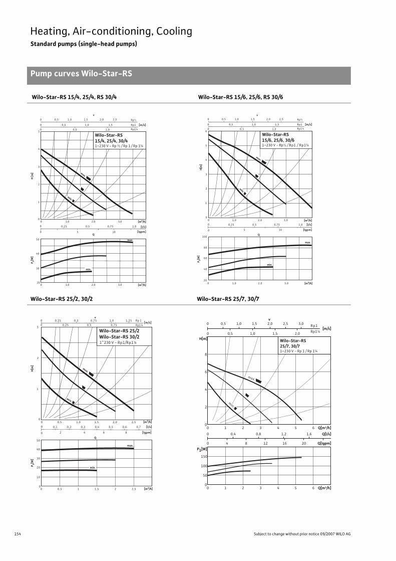
154 Subject to change without prior notice 09/2007 WILO AG
Heating, Air-conditioning, CoolingStandard pumps (single-head pumps)
Pump curves Wilo-Star-RS
Wilo-Star-RS 15/4, 25/4, RS 30/4 Wilo-Star-RS 15/6, 25/6, RS 30/6
Wilo-Star-RS 25/2, 30/2 Wilo-Star-RS 25/7, 30/7
H [m
]
0,5
1,0 0
0
0
0
1
2
3
4
5
0 1,0 2,0 3,0
0
0 5 10
0,75
1,0
1,0
1,5
Rp½
0,5
0,25 0,5 1,0
min.
1,5 0,5 2,0 2,5
[m/s] Rp1
Rp1¼
20
50
40
30
P 1[W]
[l/s]
[lgpm]
[m3/h]
0 1,0 2,0 3,0 [m3/h]
v
Q
max.
min.
max.
Wilo-Star-RS15/4, 25/4, 30/41~230 V - Rp ½ / Rp 1 / Rp 1¼
Q
00
0
0
[l/s]
[lgpm]
020
0,75
1,0
1
2
5
6
105
100
60
80
min.
1,0 2,0 3,0
0,25 0,5 1,0
2,0 3,0
4
3
max.
40
max.
Wilo-Star-RS15/6, 25/6, 30/61~230 V - Rp½ / Rp1 / Rp1¼
[m3/h]
[m3/h]
P 1[W]
0,5
1,00
0
0
1,0
1,0
1,5
Rp½
0,5
1,50,5 2,0 2,5
[m/s]Rp1
Rp1¼
v
min.
H[m
]
Q
0,50
00
0
0
0,5
[l/s]
[lgpm]
00
0,5
0,5
[m/s]
1
2
30,25
v
0
1,0
0,75
1,25
84
50
40
30
20
10
Rp 1
Rp1¼
max.
0,25
0,5
0,75
min.
max.
1,0 1,5 2,0 2,5
0,20,1 0,3
2
0,4
6
0,6 0,7
1 1,5 2 2,5
Wilo-Star-RS 25/2Wilo-Star-RS 30/21~230 V - Rp1/Rp1¼
[m3/h]
P 1[W]
H[m
]
[m3/h]
min.
[m/s]0 0,5 1,0 1,5 2,0
Q[m³/h]0 1 2 3 4 5 6
Q[l/s]0 0,4 0,8 1,2 1,6
Q[Igpm]0 4 8 12 16 20
H[m]
0
2
4
6
8
Q[m³/h]0 1 2 3 4 5 6
P1[W]
0
50
100
150
v0 0,5 1,0 1,5 2,0 2,5 3,0
Wilo-Star-RS25/7, 30/71~230 V - Rp 1 / Rp 1¼
Rp1
Rp1¼
min.
max.

155
Heating, Air-conditioning, CoolingStandard pumps (single-head pumps)
Pump curves Wilo-Star-RS
Wilo Catalogue A1 - 50 Hz - Circulating Pumps in Glandless Design
Hea
ting,
Air-
cond
ition
ing,
Co
olin
gSe
cond
ary
Hot W
ater
Circ
ulat
ion
Sola
r The
rmal
, Geo
ther
mal
En
ergy
Sys
tem
sSe
rvic
e/Ac
cess
orie
s, S
yste
ms
Switc
hgea
rs a
nd C
ontr
ol
Dev
ices
Pum
p M
anag
emen
t Sys
tem
s
Wilo-Star-RS 25/8, RS 30/8
Q[m³/h]0 1 2 3 4 5 6
Q[l/s]0 0,4 0,8 1,2 1,6
Q[Igpm]0 4 8 12 16 20
H[m]
0
2
4
6
8
Q[m³/h]0 1 2 3 4 5 6
P1[W]
0
50
100
150
[m/s]0 0,5 1,0 1,5 2,0
v0 0,5 1,0 1,5 2,0 2,5 3,0 Rp1
Rp1¼
Wilo-Star-RS25/8, 30/81~230 V - Rp 1 / Rp 1¼
min.
max.

156 Subject to change without prior notice 09/2007 WILO AG
Heating, Air-conditioning, CoolingStandard pumps (single-head pumps)
Terminal diagram, motor data Wilo-Star-RS
Terminal diagram
1-phase motor (EM) 2-pole - 1~230 V, 50 Hz,with integrated capacitor
Motor data
Wilo-Star-RS... Nominal power
Speed Power consumption
Current maximum
Motorprotection
Capacitor Threaded cable connection
P2 n P1 I – Capacity PG[W] [1/min] [W] [A] – [�F/VDB] [–]
15/4-13017.5011.50
6.50
max.
min.
272026302350
483828
0.210.170.13
not necessary (blocking current-
proof)1.7/400 1 x 11
15/6-13038.0021.0011.00
max.
min.
284027502480
846143
0.360.280.20
not necessary (blocking current-
proof)2.6/400 1 x 11
25/27.004.001.50
max.
min.
225022101660
453018
0.200.130.08
not necessary (blocking current-
proof)1.6/400 1 x 11
25/417.5011.506.50
max.
min.
272026302350
483828
0.210.170.13
not necessary (blocking current-
proof)1.7/400 1 x 11
25/638.0021.0011.00
max.
min.
284027502480
846143
0.360.280.20
not necessary (blocking current-
proof)2.6/400 1 x 11
25/759.2031.2014.80
max.
min.
280026502300
1329262
0.580.420.30
not necessary (blocking current-
proof)3.5/400 1 x 11
25/870.6039.3720.62
max.
min.
203524042122
151113
810.76
not necessary (blocking current-
proof)3.5/400 1 x 11
30/27.004.001.50
max.
min.
225022101660
453018
0.200.130.08
not necessary (blocking current-
proof)1.6/400 1 x 11
30/417.5011.506.50
max.
min.
272026302350
483828
0.210.170.13
not necessary (blocking current-
proof)1.7/400 1 x 11
30/638.0021.0011.00
max.
min.
284027502480
846143
0.360.280.20
not necessary (blocking current-
proof)2.6/400 1 x 11
30/759.2031.2014.80
max.
min.
280026502300
1329568
0.58not necessary
(blocking current-proof)
3.5/400 1x11
30/870.6039.3720.62
max.
min.
203524042122
151113
810.76
not necessary (blocking current-
proof)3.5/400 1x11
Always refer to name plate data!
L N PE

157
Heating, Air-conditioning, CoolingStandard pumps (single-head pumps)
Dimensions, weights Wilo-Star-RS
Wilo Catalogue A1 - 50 Hz - Circulating Pumps in Glandless Design
Hea
ting,
Air-
cond
ition
ing,
Co
olin
gSe
cond
ary
Hot W
ater
Circ
ulat
ion
Sola
r The
rmal
, Geo
ther
mal
En
ergy
Sys
tem
sSe
rvic
e/Ac
cess
orie
s, S
yste
ms
Switc
hgea
rs a
nd C
ontr
ol
Dev
ices
Pum
p M
anag
emen
t Sys
tem
s
Dimension drawing A Dimension drawing B
Motor horizontalTerminal-box position possible for 3, 6, 9 and 12 o’clockAt delivery terminal box position is at 3 o'clock.
Motor horizontalTerminal-box position possible for 3, 6, 9 and 12 o’clock
Dimensions, weights
Wilo-Star-RS... Pipe connection/nominal diameter
Thread Pump dimensions
Weightabout
Dimensiondrawing
Rp G I0 l1 l3 l4 a b1 b2 b3 b4 – –– – [mm] [kg] –
15/4-130 Rp 1/2 G1 130 96 65 78 34 104 93.5 58 73 2.4 A
15/6-130 Rp 1/2 G1 130 96 65 78 33 104 93.5 58 76 2.5 A
25/2 Rp 1 G 1 1/2 180 96 90 78 34 104 93.5 58 73 2.2 B
25/4 Rp 1 G 1 1/2 180 96 90 78 34 104 93.5 58 73 2.2 B
25/4-130 Rp 1 G 1 1/2 130 96 65 78 34 104 93.5 58 73 2.2 B
25/6 Rp 1 G 1 1/2 180 96 90 78 33 104 93.5 58 76 2.4 B
25/6-130 Rp 1 G 1 1/2 130 96 65 78 33 104 93.5 58 76 2.4 B
25/7 Rp 1 G 1 1/2 180 109 90 91 32 101 93.5 54 79 2.7 B
25/8 Rp 1 G 1 1/2 180 119 90 88 34 113 93.5 54 79 3.3 B
30/2 Rp 1 1/4 G 2 180 96 90 78 34 104 93.5 58 73 2.2 B
30/4 Rp 1 1/4 G 2 180 96 90 78 34 104 93.5 58 73 2.4 B
30/6 Rp 1 1/4 G 2 180 96 90 78 33 104 93.5 58 76 2.7 B
30/7 Rp 1 1/4 G 2 180 109 90 91 32 101 93.5 54 79 3.0 B
30/8 Rp 1 1/4 G 2 180 119 90 88 34 113 93.5 54 79 3.5 B
b
b2
1
l 0
l1
l4
l 3
G
a
PG 11
b2
b1
b4
l 0
l1
l4
l 3
G
PG 11
b3
a

158 Subject to change without prior notice 09/2007 WILO AG
Heating, Air-conditioning, CoolingStandard pumps (single-head pumps)

159
Heating, Air-conditioning, CoolingStandard pumps (single-head pumps)
Series description Wilo-AXL
Wilo Catalogue A1 - 50 Hz - Circulating Pumps in Glandless Design
Hea
ting,
Air-
cond
ition
ing,
Co
olin
gSe
cond
ary
Hot W
ater
Circ
ulat
ion
Sola
r The
rmal
, Geo
ther
mal
En
ergy
Sys
tem
sSe
rvic
e/Ac
cess
orie
s, S
yste
ms
Switc
hgea
rs a
nd C
ontr
ol
Dev
ices
Pum
p M
anag
emen
t Sys
tem
s
Wilo-AXL
ConstructionGlandless circulating pump with screwed connection, preselectable speed stages for power adjustment
ApplicationHot-water heating systems for all systems, air-conditioning systems, closed cooling circuits, industrial circulating systems
Type keyExample: Wilo-AXL 80/25AXL Standard pump (screw-end pump)80/ Nominal delivery head/10 [m] at Q = 0 m3/h25 Nominal connection width
Special features/product advantages• Pump housing with cataphoretic (KTL) coating for the prevention of
corrosion from condensation formation• Pump with short installation length 130 mm.
Equipment/function
Operating modes• Speed-stage switching
Manual functions• Selection of speed stages (2 speed stages)
Equipment/scope of delivery• Includes seals • Includes installation and operating instructions
Accessories• Screwed connections
Wilo-AXL
0
1
2
3
4
5
6
7
H[m
]
0 1 2
1
2
3 4 5 6 Q[m³/h]
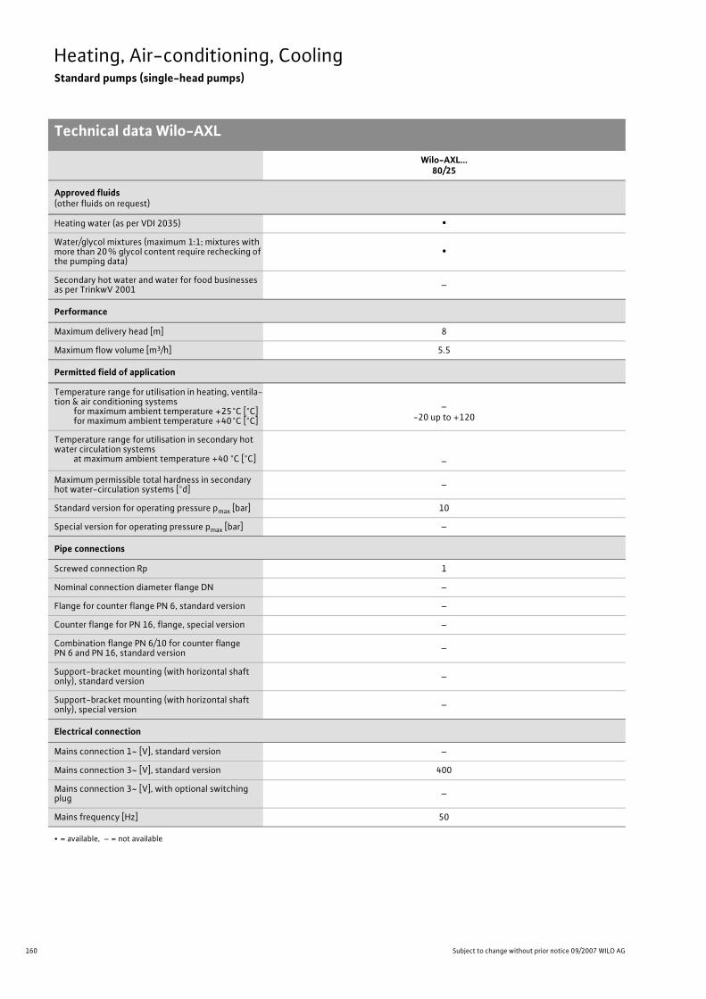
160 Subject to change without prior notice 09/2007 WILO AG
Heating, Air-conditioning, CoolingStandard pumps (single-head pumps)
Technical data Wilo-AXL
Wilo-AXL…80/25
Approved fluids(other fluids on request)
Heating water (as per VDI 2035) •Water/glycol mixtures (maximum 1:1; mixtures with more than 20% glycol content require rechecking of the pumping data)
•
Secondary hot water and water for food businesses as per TrinkwV 2001 –
Performance
Maximum delivery head [m] 8
Maximum flow volume [m3/h] 5.5
Permitted field of application
Temperature range for utilisation in heating, ventila-tion & air conditioning systems
for maximum ambient temperature +25°C [°C]for maximum ambient temperature +40°C [°C]
–-20 up to +120
Temperature range for utilisation in secondary hot water circulation systems
at maximum ambient temperature +40 °C [°C] –
Maximum permissible total hardness in secondary hot water-circulation systems [°d] –
Standard version for operating pressure pmax [bar] 10
Special version for operating pressure pmax [bar] –
Pipe connections
Screwed connection Rp 1
Nominal connection diameter flange DN –
Flange for counter flange PN 6, standard version –
Counter flange for PN 16, flange, special version –
Combination flange PN 6/10 for counter flangePN 6 and PN 16, standard version –
Support-bracket mounting (with horizontal shaft only), standard version –
Support-bracket mounting (with horizontal shaft only), special version –
Electrical connection
Mains connection 1~ [V], standard version –
Mains connection 3~ [V], standard version 400
Mains connection 3~ [V], with optional switching plug –
Mains frequency [Hz] 50
• = available, – = not available

161
Heating, Air-conditioning, CoolingStandard pumps (single-head pumps)
Technical data Wilo-AXL
Wilo Catalogue A1 - 50 Hz - Circulating Pumps in Glandless Design
Hea
ting,
Air-
cond
ition
ing,
Co
olin
gSe
cond
ary
Hot W
ater
Circ
ulat
ion
Sola
r The
rmal
, Geo
ther
mal
En
ergy
Sys
tem
sSe
rvic
e/Ac
cess
orie
s, S
yste
ms
Switc
hgea
rs a
nd C
ontr
ol
Dev
ices
Pum
p M
anag
emen
t Sys
tem
s
Motor/electronics
Electromagnetic compatibility –
Emitted interference –
Immunity to interference –
Power electronics –
Protection class IP 42
Insulation class F
Materials
Pump housing Cast iron (EN-GJL-200)
Impeller Plastic (PPE, trade name Noryl)
Shaft Stainless steel (X46 Cr13)
Bearing Metal-impregnated carbon
Minimum suction head at suction port [m]for the prevention of cavitation at water delivery temperature
50 °C 0.5
95 °C 3
110 °C 10
130 °C –
Wilo-AXL…80/25
• = available, – = not available

162 Subject to change without prior notice 09/2007 WILO AG
Heating, Air-conditioning, CoolingStandard pumps (single-head pumps)
Pump curve, terminal diagram, motor data Wilo-AXL
Wilo-AXL 80/25-130
Terminal diagram A - stage 2 (maximum) Terminal diagram B - stage 1 (minimum)
Mains connection 3~400 V, 50 HzBlocking current-proof, no motor protection required
Mains connection 3~400 V, 50 HzBlocking current-proof, no motor protection required
Motor data
Wilo-AXL... Nominal power Speed Power consumption Current Terminal diagramP2 n P1 I -
[W] [1/min] [W] [A] -
80/25-130 80 maximum 2440minimum 1710
maximum 190minimum 100
maximum 0.38minimum 0.18
AB
Always refer to name plate data!Current I: Onsite thermal overload settings.
Wilo-AXL
0
1
min.2
3
4
5
6
0 1 2 3 4 5 6
H[m
]
Q[m³/h]
max.
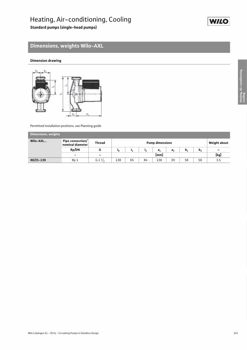
163
Heating, Air-conditioning, CoolingStandard pumps (single-head pumps)
Dimensions, weights Wilo-AXL
Wilo Catalogue A1 - 50 Hz - Circulating Pumps in Glandless Design
Hea
ting,
Air-
cond
ition
ing,
Co
olin
gSe
cond
ary
Hot W
ater
Circ
ulat
ion
Sola
r The
rmal
, Geo
ther
mal
En
ergy
Sys
tem
sSe
rvic
e/Ac
cess
orie
s, S
yste
ms
Switc
hgea
rs a
nd C
ontr
ol
Dev
ices
Pum
p M
anag
emen
t Sys
tem
s
Dimension drawing
Permitted installation positions, see Planning guide
Dimensions, weights
Wilo-AXL... Pipe connection/nominal diameter Thread Pump dimensions Weight about
Rp/DN G I0 I1 I2 a1 a2 b1 b2 –- – [mm] [kg]
80/25-130 Rp 1 G 1 1/2 130 65 84 138 39 50 50 3.5
l 2
a2 a1
b1 b2
l 0
l 1

164 Subject to change without prior notice 09/2007 WILO AG
Heating, Air-conditioning, CoolingStandard pumps (single-head pumps)
Series description Wilo-TOP-RL
Wilo-TOP-RL
ConstructionGlandless circulating pump with screwed connection or flange con-nection. Preselectable speed stages for power adjustment
ApplicationHot-water heating systems for all systems, air-conditioning systems, closed cooling circuits, industrial circulating systems
Type keyExample: Wilo-TOP-RL 40/4TOP-RL Standard pump (screw-end or flange-end pump)40/ Nominal connection width4 Nominal delivery head [m] when Q = 0 m3/h
Special features/product advantages• Can be used in heating systems and in cooling/air-conditioning sys-
tems from -20 °C to +130 °C• Manual power adjustment with 3 speed stages.• Pump housing with cataphoretic (KTL) coating for the prevention of
corrosion from condensation formation• Easy installation using combination flange PN 6/PN 10 (with DN 40)• Protection class IP 44
ATTENTION:For EEI classification for each pump model see Chapter “Planning guide”, Table on page 20.
Q[m³/h]1 2 3 4 5 6 7 8 9 10
H[m]
0
1
2
3
4
5
6
7
30/6,5
25/7,5, 30/7,5
30/4, 40/4
Wilo-TOP-RL

165
Heating, Air-conditioning, CoolingStandard pumps (single-head pumps)
Series description Wilo-TOP-RL
Wilo Catalogue A1 - 50 Hz - Circulating Pumps in Glandless Design
Hea
ting,
Air-
cond
ition
ing,
Co
olin
gSe
cond
ary
Hot W
ater
Circ
ulat
ion
Sola
r The
rmal
, Geo
ther
mal
En
ergy
Sys
tem
sSe
rvic
e/Ac
cess
orie
s, S
yste
ms
Switc
hgea
rs a
nd C
ontr
ol
Dev
ices
Pum
p M
anag
emen
t Sys
tem
s
Equipment/function
Operating modes• Speed-stage switching
Manual functions• Selection of speed stages (3 speed stages)
Automatic functions• Full motor protection with integrated trip electronics
(optional for all types with Wilo-Protect-Module C)
External control functions• Control input “Overriding Off”
(optional for all types with Wilo-Protect-Module C)
Signal and display functions• Individual/collective fault signal (potential-free NC contact)
(optional for all types with Wilo-Protect-Module C)• Collective fault signal (potential-free NC contact)
(optional for all types with Wilo-Protect-Module C)• Individual run signal (potential-free NO contact)
(optional for all types with Wilo-Protect-Module C)• Fault signal light
(optional for all types with Wilo-Protect-Module C)
Dual pump management (twin-head pump or 2 x single-head pumps)• Main/standby operation (automatic fault-actuated switchover /
time-dependent pump alteration) (optional for all types with Wilo-Protect-Module C)
Equipment/scope of delivery• Including seals for threaded connection (loose)• Includes installation and operating instructions• Including washers for flange bolts (for nominal connection width DN 40)
Accessories• Screwed connections• Cold water insulation for pumps Wilo-ClimaForm• Wilo-Protect-Module C for single-head pumps (1~230 V)

166 Subject to change without prior notice 09/2007 WILO AG
Heating, Air-conditioning, CoolingStandard pumps (single-head pumps)
Technical data Wilo-TOP-RL
Wilo-TOP-RL...
25/7.5 30/4 30/6.5 30/7.5 40/4
Approved fluids(other fluids on request)
Heating water (as per VDI 2035) • • • • •Water/glycol mixtures (maximum 1:1; mixtures with more than 20% glycol content require rechecking of the pumping data)
• • • • •
Secondary hot water and water for food businesses as per TrinkwV 2001 – – – – –
Performance
Maximum delivery head [m] 7.5 4.0 7.0 7.5 4.5
Maximum flow volume [m3/h] 6.5 9.0 10.0 6.5 14
Permitted field of application
Temperature range for utilisation in HVAC systemswith maximum ambient temperature +25°C [°C]with maximum ambient temperature +40°C [°C]
–-20 to +130 (in short-term operation 2 h: +140)
(for utilisation with Wilo-Protect-Module C: -20 to +110)
Temperature range for utilisation in secondary hot water circulation systems
at maximum ambient temperature +40 °C [°C] – – – – –
Maximum permissible total hardness in secondary hot water-circulation systems [°d] – – – – –
Standard version for operating pressure pmax [bar] 10 10 10 10 6/10
Special version for operating pressure pmax [bar] – – – – –
Pipe connections
Screwed connection Rp 1 1 1/4 1 1/4 1 1/4 –
Nominal connection diameter flange DN – – – – 40
Flange for counter flange PN 6, standard version – – – – –
Counter flange for PN 16, flange, special version – – – – –
Combination flange PN 6/10 for counter flange PN 6 and PN 16, standard version – – – – •
Support-bracket mounting (with horizontal shaft only), standard version – – – – –
Support-bracket mounting (with horizontal shaft only), special version – – – – –
Electrical connection
Mains connection 1~ [V], standard version 230 230 230 230 230
Mains connection 3~ [V], standard version – – – – –
Mains connection 3~ [V], with optional switching plug – – – – –
Mains frequency [Hz] 50 50 50 50 50
• = available, – = not available

167
Heating, Air-conditioning, CoolingStandard pumps (single-head pumps)
Technical data Wilo-TOP-RL
Wilo Catalogue A1 - 50 Hz - Circulating Pumps in Glandless Design
Hea
ting,
Air-
cond
ition
ing,
Co
olin
gSe
cond
ary
Hot W
ater
Circ
ulat
ion
Sola
r The
rmal
, Geo
ther
mal
En
ergy
Sys
tem
sSe
rvic
e/Ac
cess
orie
s, S
yste
ms
Switc
hgea
rs a
nd C
ontr
ol
Dev
ices
Pum
p M
anag
emen
t Sys
tem
s
Motor/electronics
Electromagnetic compatibility – – – – –
Emitted interference EN 61000-6-3
Immunity to interference EN 61000-6-2
Power electronics – – – – –
Protection class IP 44 IP 44 IP 44 IP 44 IP 44
Insulation class F F F F F
Materials
Pump housing Cast iron (EN-GJL-200) Cast iron (EN-GJL-250)
Impeller Plastic (PPE, trade name Noryl)Plastic
(PPE, trade name Noryl)
Shaft Stainless steel (X46 Cr13) Stainless steel (X46 Cr13)
Bearing Metal-impregnated carbon Metal-impreg-nated carbon
Minimum suction head at suction port [m]for the prevention of cavitation at water delivery temperature
50 °C 0.5 0.5 0.5 0.5 0.5
95 °C 5.0 5.0 5.0 5.0 5.0
110 °C 11.0 11.0 11.0 11.0 11.0
130 °C 24.0 24.0 24.0 24.0 24.0
Wilo-TOP-RL...
25/7.5 30/4 30/6.5 30/7.5 40/4
• = available, – = not available
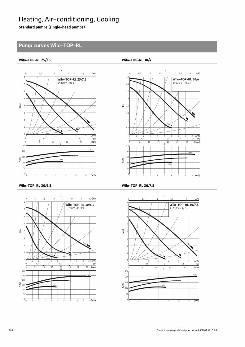
168 Subject to change without prior notice 09/2007 WILO AG
Heating, Air-conditioning, CoolingStandard pumps (single-head pumps)
Pump curves Wilo-TOP-RL
Wilo-TOP-RL 25/7.5 Wilo-TOP-RL 30/4
Wilo-TOP-RL 30/6.5 Wilo-TOP-RL 30/7.5
0
0
0
50
100
150
200
250
00
0 5 10 15Q
20
0,5 1,511 2 3 4 5 6 [m³/h]
0 1 2 3 4 5 6 [m³/h]
[l/s]
[Igpm]
1
2
3
4
5
6
7
8
0,5 1,5 2 [m/s]v
1
Wilo-TOP-RL 25/7,51~230 V - Rp 1
H[m
]P 1[
W]
max.
min.
max.
min.
Q
0
0 1 2 3 4 5 6 7 8 9 [m³/h]
0 1 2 3 4 5 6 7 8 9 [m³/h]
0 0,5 1,51 2,52 [l/s]
0 5 10 15 20 25 30 [Igpm]
0,5 1,5 2,52 3 [m/s]v
1
Wilo-TOP-RL 30/41~230 V - Rp 1¼
0
0,5
1,0
1,5
2,0
2,5
3,0
3,5
4,0
H[m
]
0
50
100
150
200
250
P 1[W
]
max.
min.
max.
min.
0 1 2 3 4 5 6 7 8 9 10 [m³/h]
00 0,5 1,51 2,52
1 2 3 4 5 6 7 8 9 10 [m³/h][l/s]
0 5 10 15Q
20 25 30 35 [Igpm]
0 0,5 1,5 2 [m/s]v
1 3 3,52,5
0
1
2
3
4
5
6
7
8
H[m
]
0
50
100
150
200
250
300
P 1[W
]
max.
min.
Wilo-TOP-RL 30/6,51~230 V - Rp 1¼
min.
max.
Wilo-TOP-RL 30/7,51~230 V - Rp 1¼
00 1 2 3 4 5 6 [m³/h]
0 1 2 3 4 5 6 [m³/h]
0 0,5 1,51 [l/s]
0 5 10 15Q
20 [Igpm]
1
2
3
4
5
6
7
8
0 0,5 1,5 2 [m/s]v
1
H[m
]
0
50
100
150
200
250
P 1[W
]
max.
min.
max.
min.

169
Heating, Air-conditioning, CoolingStandard pumps (single-head pumps)
Pump curves Wilo-TOP-RL
Wilo Catalogue A1 - 50 Hz - Circulating Pumps in Glandless Design
Hea
ting,
Air-
cond
ition
ing,
Co
olin
gSe
cond
ary
Hot W
ater
Circ
ulat
ion
Sola
r The
rmal
, Geo
ther
mal
En
ergy
Sys
tem
sSe
rvic
e/Ac
cess
orie
s, S
yste
ms
Switc
hgea
rs a
nd C
ontr
ol
Dev
ices
Pum
p M
anag
emen
t Sys
tem
s
Wilo-TOP-RL 40/4
H [m
]P 1
[W]
0 1 2
0
0
50
100
150
200
1
2
3
4
5
10 2 30 1 2 3 [l/s]
0 5 10 15 20 25 30 35 [Igpm]
4 5 6 7 8 9 10 [m³/h]
10 2 3 4 5 6 7 8 9 10 [m³/h]
v[m/s]
Wilo-TOP-RL 40/41~230V - DN40
Qmax.
min.
min.
max.
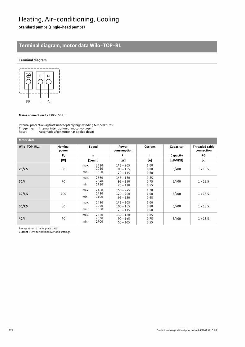
170 Subject to change without prior notice 09/2007 WILO AG
Heating, Air-conditioning, CoolingStandard pumps (single-head pumps)
Terminal diagram, motor data Wilo-TOP-RL
Terminal diagram
Mains connection 1~230 V, 50 Hz
Internal protection against unacceptably high winding temperaturesTriggering: Internal interruption of motor voltageReset: Automatic after motor has cooled down
Motor data
Wilo-TOP-RL... Nominal power
Speed Power consumption
Current Capacitor Threaded cable connection
P2 n P1 I Capacity PG[W] [1/min] [W] [A] [�F/VDB] [-]
25/7.5 80max. 2420
1950 min. 1350
145 - 205100 - 165
70 - 115
1.000.800.60
5/400 1 x 13.5
30/4 70max. 2660
2340min. 1710
145 - 18095 - 15070 - 110
0.850.750.55
5/400 1 x 13.5
30/6.5 100max. 2160
1480min. 1100
150 - 245120 - 200
95 - 130
1.201.000.65
5/400 1 x 13.5
30/7.5 80max. 2420
1950min. 1350
145 - 205100 - 165
70 - 115
1.000.800.60
5/400 1 x 13.5
40/4 70max. 2660
2330min. 1700
130 - 18090 - 14560 - 105
0.850.750.55
5/400 1 x 13.5
Always refer to name plate data!Current I: Onsite thermal overload settings.
L NPE
NL
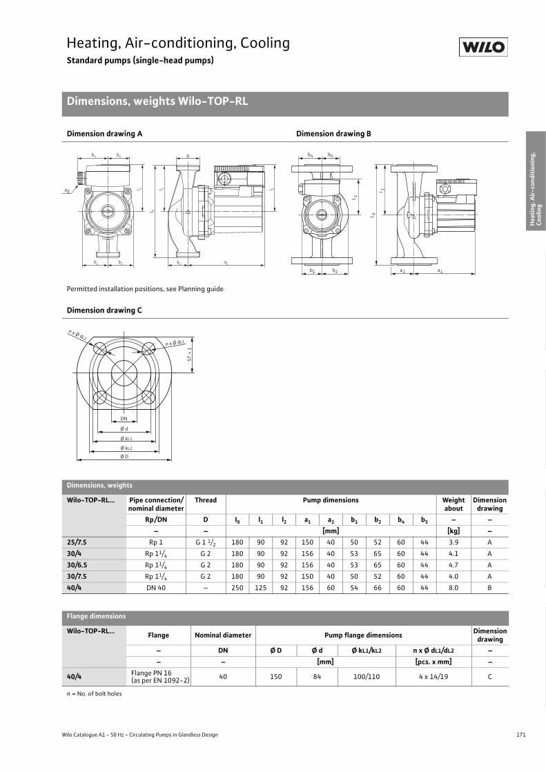
171
Heating, Air-conditioning, CoolingStandard pumps (single-head pumps)
Dimensions, weights Wilo-TOP-RL
Wilo Catalogue A1 - 50 Hz - Circulating Pumps in Glandless Design
Hea
ting,
Air-
cond
ition
ing,
Co
olin
gSe
cond
ary
Hot W
ater
Circ
ulat
ion
Sola
r The
rmal
, Geo
ther
mal
En
ergy
Sys
tem
sSe
rvic
e/Ac
cess
orie
s, S
yste
ms
Switc
hgea
rs a
nd C
ontr
ol
Dev
ices
Pum
p M
anag
emen
t Sys
tem
s
Dimension drawing A Dimension drawing B
Permitted installation positions, see Planning guide
Dimension drawing C
Dimensions, weights
Wilo-TOP-RL... Pipe connection/nominal diameter
Thread Pump dimensions Weight about
Dimensiondrawing
Rp/DN D I0 l1 l2 a1 a2 b1 b2 b4 b5 – –– – [mm] [kg] –
25/7.5 Rp 1 G 1 1/2 180 90 92 150 40 50 52 60 44 3.9 A
30/4 Rp 11/4 G 2 180 90 92 156 40 53 65 60 44 4.1 A
30/6.5 Rp 11/4 G 2 180 90 92 156 40 53 65 60 44 4.7 A
30/7.5 Rp 11/4 G 2 180 90 92 150 40 50 52 60 44 4.0 A
40/4 DN 40 – 250 125 92 156 60 54 66 60 44 8.0 B
Flange dimensions
Wilo-TOP-RL... Flange Nominal diameter Pump flange dimensions Dimensiondrawing
– DN Ø D Ø d Ø kL1/kL2 n x Ø dL1/dL2 –– – [mm] [pcs. x mm] –
40/4 Flange PN 16 (as per EN 1092-2) 40 150 84 100/110 4 x 14/19 C
n = No. of bolt holes
Pg
b1 b2 a1a2
l 3 l 1 l 2
b4 b5
l 0D
l 2
l 1
l 0
b4 b5
b1 b2 a2 a1
57 +
1 n x Ø dL1
n x Ø dL2
Ø kL1
Ø kL2
DN
Ø d
Ø D
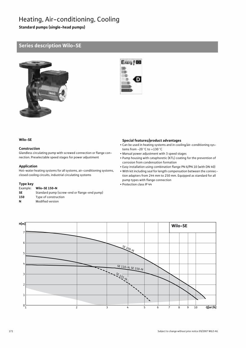
172 Subject to change without prior notice 09/2007 WILO AG
Heating, Air-conditioning, CoolingStandard pumps (single-head pumps)
Series description Wilo-SE
Wilo-SE
ConstructionGlandless circulating pump with screwed connection or flange con-nection. Preselectable speed stages for power adjustment
ApplicationHot-water heating systems for all systems, air-conditioning systems, closed cooling circuits, industrial circulating systems
Type keyExample: Wilo-SE 150-NSE Standard pump (screw-end or flange-end pump)150 Type of constructionN Modified version
Special features/product advantages• Can be used in heating systems and in cooling/air-conditioning sys-
tems from -20 °C to +130 °C• Manual power adjustment with 3 speed stages• Pump housing with cataphoretic (KTL) coating for the prevention of
corrosion from condensation formation• Easy installation using combination flange PN 6/PN 10 (with DN 40)• With kit including seal for length compensation between the connec-
tion adapters from 244 mm to 250 mm. Equipped as standard for all pump types with flange connection
• Protection class IP 44
Q[m³/h]109876543210
1
2
3
4
5
6
7
H[m]
SE 110-N, SE 150-N
SE 200-N
SE 125-N
Wilo-SE

173
Heating, Air-conditioning, CoolingStandard pumps (single-head pumps)
Series description Wilo-SE
Wilo Catalogue A1 - 50 Hz - Circulating Pumps in Glandless Design
Hea
ting,
Air-
cond
ition
ing,
Co
olin
gSe
cond
ary
Hot W
ater
Circ
ulat
ion
Sola
r The
rmal
, Geo
ther
mal
En
ergy
Sys
tem
sSe
rvic
e/Ac
cess
orie
s, S
yste
ms
Switc
hgea
rs a
nd C
ontr
ol
Dev
ices
Pum
p M
anag
emen
t Sys
tem
s
Equipment/function
Operating modes• Speed-stage switching
Manual functions• Selection of speed stages (3 speed stages)
External control functions• Control input “Overriding Off”
(optional for all types with Wilo-Protect-Module C)
Signal and display functions• Individual/collective fault signal (potential-free NC contact)
(optional for all types with Wilo-Protect-Module C)• Collective fault signal (potential-free NC contact)
(optional for all types with Wilo-Protect-Module C)• Individual run signal (potential-free NO contact)
(optional for all types with Wilo-Protect-Module C)• Fault signal light
(optional for all types with Wilo-Protect-Module C)
Dual pump management (twin-head pump or 2 x single-head pumps)• Main/standby operation (automatic fault-actuated switchover /
time-dependent pump alteration) (optional for all types with Wilo-Protect-Module C)
Equipment/scope of delivery• Including seals for threaded connection (loose)• Including installation and operating instructions• Including washers for flange bolts (for nominal connection width DN 40)
Accessories• Screwed connections with screw thread• Cold water insulation for pumps Wilo-ClimaForm• Wilo-Protect-Module C for single-head pumps (1~230 V)
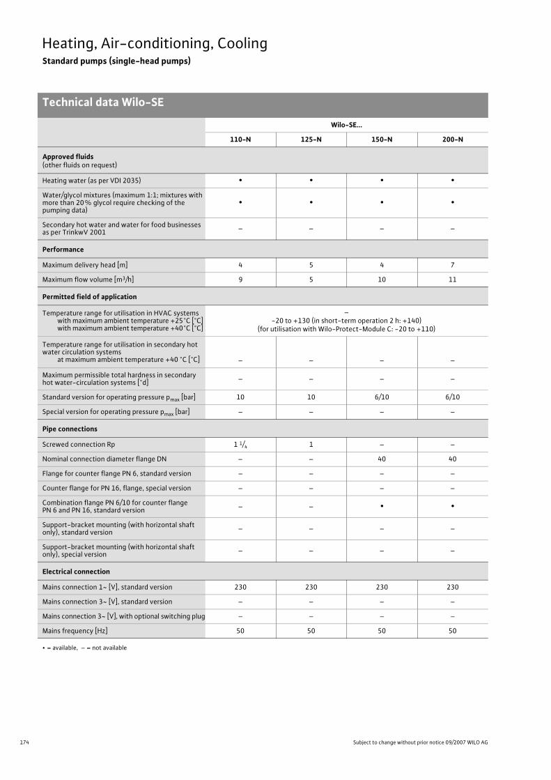
174 Subject to change without prior notice 09/2007 WILO AG
Heating, Air-conditioning, CoolingStandard pumps (single-head pumps)
Technical data Wilo-SE
Wilo-SE...
110-N 125-N 150-N 200-N
Approved fluids(other fluids on request)
Heating water (as per VDI 2035) • • • •Water/glycol mixtures (maximum 1:1; mixtures with more than 20% glycol require checking of the pumping data)
• • • •
Secondary hot water and water for food businesses as per TrinkwV 2001 – – – –
Performance
Maximum delivery head [m] 4 5 4 7
Maximum flow volume [m3/h] 9 5 10 11
Permitted field of application
Temperature range for utilisation in HVAC systemswith maximum ambient temperature +25°C [°C]with maximum ambient temperature +40°C [°C]
–-20 to +130 (in short-term operation 2 h: +140)
(for utilisation with Wilo-Protect-Module C: -20 to +110)
Temperature range for utilisation in secondary hot water circulation systems
at maximum ambient temperature +40 °C [°C] – – – –
Maximum permissible total hardness in secondary hot water-circulation systems [°d] – – – –
Standard version for operating pressure pmax [bar] 10 10 6/10 6/10
Special version for operating pressure pmax [bar] – – – –
Pipe connections
Screwed connection Rp 1 1/4 1 – –
Nominal connection diameter flange DN – – 40 40
Flange for counter flange PN 6, standard version – – – –
Counter flange for PN 16, flange, special version – – – –
Combination flange PN 6/10 for counter flange PN 6 and PN 16, standard version – – • •
Support-bracket mounting (with horizontal shaft only), standard version – – – –
Support-bracket mounting (with horizontal shaft only), special version – – – –
Electrical connection
Mains connection 1~ [V], standard version 230 230 230 230
Mains connection 3~ [V], standard version – – – –
Mains connection 3~ [V], with optional switching plug – – – –
Mains frequency [Hz] 50 50 50 50
• = available, – = not available

175
Heating, Air-conditioning, CoolingStandard pumps (single-head pumps)
Technical data Wilo-SE
Wilo Catalogue A1 - 50 Hz - Circulating Pumps in Glandless Design
Hea
ting,
Air-
cond
ition
ing,
Co
olin
gSe
cond
ary
Hot W
ater
Circ
ulat
ion
Sola
r The
rmal
, Geo
ther
mal
En
ergy
Sys
tem
sSe
rvic
e/Ac
cess
orie
s, S
yste
ms
Switc
hgea
rs a
nd C
ontr
ol
Dev
ices
Pum
p M
anag
emen
t Sys
tem
s
Motor/electronics
Electromagnetic compatibility – – – –
Emitted interference EN 61000-6-3
Immunity to interference EN 61000-6-2
Power electronics – – – –
Protection class IP 44 IP 44 IP 44 IP 44
Insulation class F F F F
Materials
Pump housing Cast iron (EN-GJL-200) Cast iron (EN-GJL-250)
Impeller Plastic (PPE, trade name: Noryl)
Shaft Stainless steel (X40 Cr13)
Bearing Metal-impregnated carbon
Minimum suction head at suction port [m]for the prevention of cavitation at water delivery temperature
50 °C 0.5 0.5 0.5 0.5
95 °C 5 5 5 5
110 °C 11 11 11 11
130 °C 24 24 24 24
Wilo-SE...
110-N 125-N 150-N 200-N
• = available, – = not available

176 Subject to change without prior notice 09/2007 WILO AG
Heating, Air-conditioning, CoolingStandard pumps (single-head pumps)
Pump curves Wilo-SE
Wilo-SE 110-N Wilo-SE 125-N
Wilo-SE 150-N Wilo-SE 200-N
P 1[W]
H[m
]
0 0,5 1 1,5 2 2,5
0 5 10 15 20 25 30
0 1 2 3 4 5 6 7 8 9
0 1 2 3 4 5 6 7 8 9 [m³/h]
[m³/h]
Q[lgpm]
200
175
150
125
100
75
50
25
0
5
4
3
2
1
0
[l/s]
max.
min.
0 0,5 1 1,5 2 2,5 3v
[m/s]
Wilo-SE 110-N1~230V - Rp1¼
min.
max.
0 1 2 3 4 5 6
0 1 2 3 4 5 6 [m 3/h]
Q
[m 3/h]
150
125
100
75
50
25
0
6
5
4
3
2
1
0
0 0,5 1 1,5
0 5 10 15 20 [lgpm]
[l/s]
min.
min.
max.
0 1 2 3v
[m/s]m
ax.
P 1[W]
H[m
]
Wilo-SE 125-N1~230V - Rp1
H [m
]P 1
[W]
0 1 2
0
0
50
100
150
200
1
2
3
4
5
10 2 30 1 2 3 [l/s]
0 5 10 15 20 25 30 35 [Igpm]
4 5 6 7 8 9 10 [m³/h]
10 2 3 4 5 6 7 8 9 10 [m³/h]
v[m/s]
Wilo-SE 150-N1~230V - DN40
Q
max.
min.
min.
max.
H [m
]P 1
[W]
max.
0 1 2
0
50
100
150
200
250
1
2
3
4
5
6
7
8
10 2 30 1 2 3 [l/s]
0 5 10 15 20 25 30 35 [Igpm]
4 5 6 7 8 9 10 [m³/h]
10 2 3 4 5 6 7 8 9 10 [m³/h]
v[m/s]
min.
min.
max.
Wilo-SE 200-N1~230V - DN40
Q

177
Heating, Air-conditioning, CoolingStandard pumps (single-head pumps)
Terminal diagram, motor data Wilo-SE
Wilo Catalogue A1 - 50 Hz - Circulating Pumps in Glandless Design
Hea
ting,
Air-
cond
ition
ing,
Co
olin
gSe
cond
ary
Hot W
ater
Circ
ulat
ion
Sola
r The
rmal
, Geo
ther
mal
En
ergy
Sys
tem
sSe
rvic
e/Ac
cess
orie
s, S
yste
ms
Switc
hgea
rs a
nd C
ontr
ol
Dev
ices
Pum
p M
anag
emen
t Sys
tem
s
Terminal diagram/motor protection
Mains connection 1~230 V, 50 Hz
Internal protection against unacceptably high winding temperaturesTriggering: Internal interruption of motor voltageReset: Automatic after motor has cooled down
Motor data
Wilo-SE... Nominal power
Speed Power consumption
Current Capacitor Cable screwed connection
P2 n P1 I Capacity PG[W] [1/min] [W] [A] [�F/VDB] [-]
110-N 70max. 2660
2340min. 1740
145 - 180 95 - 150 70 - 110
0.850.750.55
5/400 1 x 13.5
125-N 50 max. 2320
1640 min. 1200
100 - 140 75 - 110 55 - 75
0.650.550.35
3.7/400 1 x 13.5
150-N 70max. 2660
2330min. 1700
130 - 18090 - 14560 - 105
0.850.750.55
5/400 1 x 13.5
200-N 100max. 2080
1410min. 920
145 - 245125 - 200100 - 135
1.201.000.70
5/400 1 x 13.5
Always refer to name plate data!Current I: Onsite thermal overload settings.
L NPE
NL

178 Subject to change without prior notice 09/2007 WILO AG
Heating, Air-conditioning, CoolingStandard pumps (single-head pumps)
Dimensions, weights Wilo-SE
Dimension drawing A Dimension drawing B
Dimension drawing C
Dimensions, weights
Wilo-SE... Pipe connection/nominal diameter Thread Pump dimensions Weight
aboutDimension
drawingRp/DN D I0 l1 L2 a1 a2 b1 b2 b4 b5 – –
– – [mm] [kg] –110-N Rp 1 1/4 G 2 180 90 92 156 50 53 65 60 44 4.1 A
125-N Rp 1 G 1 1/2 180 90 92 150 40 50 52 60 44 3.7 A
150-N DN 40 – 244 122 92 156 60 54 66 60 44 7.3 B
200-N DN 40 – 244 122 92 156 60 54 66 60 44 7.9 B
Flange dimensions
Wilo-SE... Flange Nominal diameter Pump flange dimensions Dimension
drawing– DN Ø D Ø d Ø kL1/kL2 n x Ø dL1/dL2 –– – [mm] [pcs. x mm] –
150-N Flange PN 16 (as per EN 1092-2) 40 150 84 100/110 4 x 14/19 C
200-N Flange PN 16 (as per EN 1092-2) 40 150 84 100/110 4 x 14/19 C
n = No. of bolt holes
Pg
b1 b2 a1a2
l 3 l 1 l 2
b4 b5
l 0
D
l 2
l 1
l 0
b4 b5
b1 b2 a2 a1
57 +
1 n x Ø dL1
n x Ø dL2
Ø kL1
Ø kL2
DN
Ø d
Ø D

Wilo-Star-RS.
Multiply proven technology.For heating and air-conditioning systems.
In single and multi-family houses.Convenient and reliable.
The Wilo-Star-RS is an extremely reliable standard pump for utilisation in single andmulti-family houses. It offers perfected pump technology for the highest demandson heating and air-conditioning systems, and has already proven itself multiple times during their many years of use. The Wilo-Star-RS can be installed very easily. And, with its three speed stages, it can be optimally adapted to loads at any time.Perfect? We call this Pumpen Intelligenz.
www.wilo.com
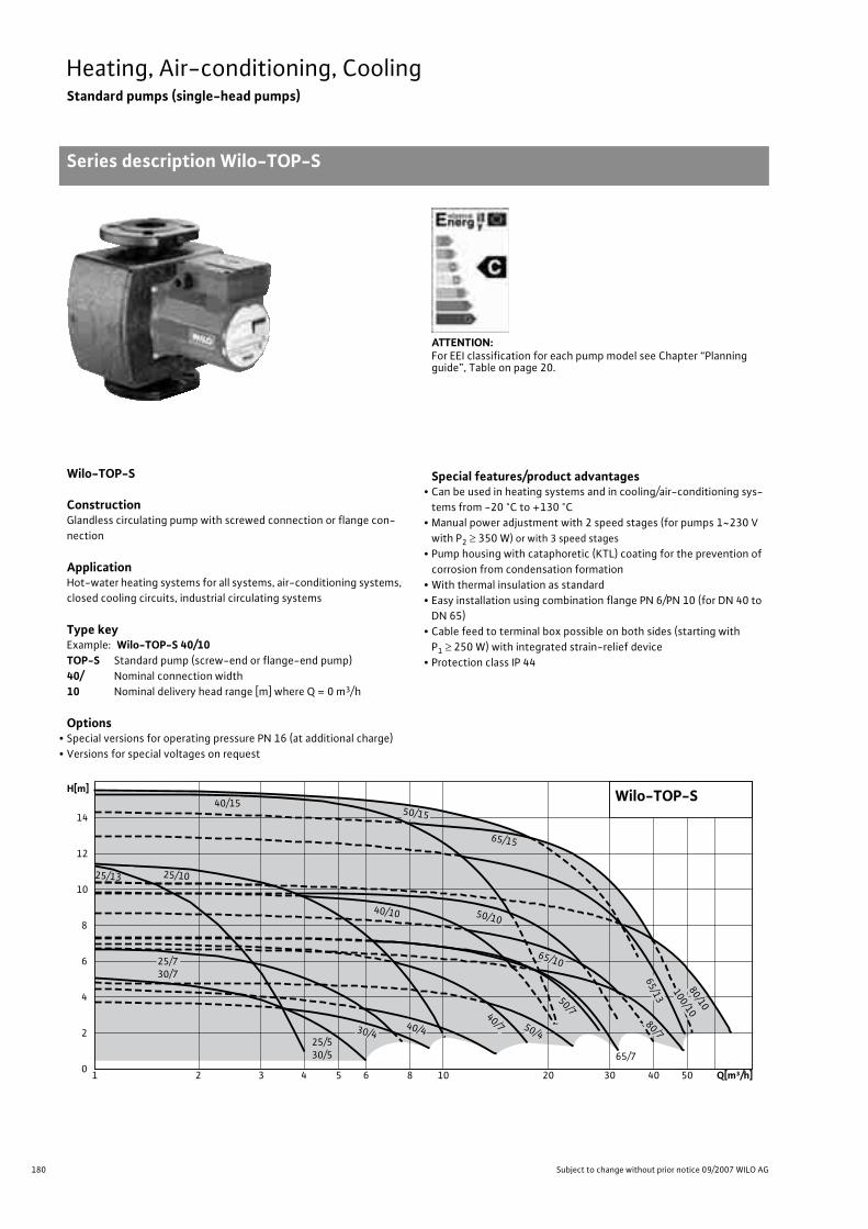
180 Subject to change without prior notice 09/2007 WILO AG
Heating, Air-conditioning, CoolingStandard pumps (single-head pumps)
Series description Wilo-TOP-S
Wilo-TOP-S
ConstructionGlandless circulating pump with screwed connection or flange con-nection
ApplicationHot-water heating systems for all systems, air-conditioning systems, closed cooling circuits, industrial circulating systems
Type keyExample: Wilo-TOP-S 40/10TOP-S Standard pump (screw-end or flange-end pump)40/ Nominal connection width10 Nominal delivery head range [m] where Q = 0 m3/h
Options• Special versions for operating pressure PN 16 (at additional charge)• Versions for special voltages on request
Special features/product advantages• Can be used in heating systems and in cooling/air-conditioning sys-
tems from -20 °C to +130 °C• Manual power adjustment with 2 speed stages (for pumps 1~230 V
with P2 � 350 W) or with 3 speed stages• Pump housing with cataphoretic (KTL) coating for the prevention of
corrosion from condensation formation• With thermal insulation as standard• Easy installation using combination flange PN 6/PN 10 (for DN 40 to
DN 65)• Cable feed to terminal box possible on both sides (starting with
P1 � 250 W) with integrated strain-relief device• Protection class IP 44
ATTENTION:For EEI classification for each pump model see Chapter “Planning guide”, Table on page 20.
65/725/530/5
25/1025/13
40/15
40/10
50/4
50/7
65/10
80/7
80/10
100/10
65/13
65/15
50/15
50/10
40/4
25/730/7
40/730/4
Wilo-TOP-S
Q[m³/h]1 2 3 4 5 6 8 10 20 30 40 50
H[m]
0
2
4
6
8
10
12
14

181
Heating, Air-conditioning, CoolingStandard pumps (single-head pumps)
Series description Wilo-TOP-S
Wilo Catalogue A1 - 50 Hz - Circulating Pumps in Glandless Design
Hea
ting,
Air-
cond
ition
ing,
Co
olin
gSe
cond
ary
Hot W
ater
Circ
ulat
ion
Sola
r The
rmal
, Geo
ther
mal
En
ergy
Sys
tem
sSe
rvic
e/Ac
cess
orie
s, S
yste
ms
Switc
hgea
rs a
nd C
ontr
ol
Dev
ices
Pum
p M
anag
emen
t Sys
tem
s
Equipment/function
Operating modes• Speed stage switching:
Manual functions• Setting the speed stages: 3 speed stages (2 speed stages for
1~pumps with P2 � 350 W)
Automatic functions• Full motor protection with integrated trip electronics
(standard equipment only for 3~pumps with P2 � 180 W and 1~pumps with P2 � 350 W, optional for all types with Wilo-Protect-Module C)
External control functions• Control input “Overriding Off”
(optional for all types with Wilo-Protect-Module C)
Signal and display functions• Individual/collective fault signal (potential-free NC contact)
(optional for all types with Wilo-Protect-Module C)collective fault signal (potential-free NC contact) (standard equipment only for 3~pumps with P2 � 180 W and 1~pumps with P2 � 350 W, optional for all types with Wilo-Protect-Module C)
• Individual run signal (potential-free NO contact)(optional for all types with Wilo-Protect-Module C)
• Thermal winding contact (WSK, potential-free NC contact)only for 1~pumps with P2 180 W)
• Fault signal light (standard equipment only for 3~pumps with P2 � 180 W and 1~pumps with P2 � 350 W, optional for all types with Wilo-Protect-Module C)
• Direction-of-rotation control lamp
Dual pump management (twin-head pump or 2 x single-head pumps)
• Main/standby operation (automatic fault-actuated switchover/me-sensitive pump alteration): (optional for all types with Wilo-Protect-Module C)
Equipment/scope of delivery• Cable feed possible from both sides (only with 1~pumps and
3~pumps with P2 � 180 W)• Including seals for threaded connection (loose)• Including installation and operating instructions• Including thermal insulation• Including washers for flange bolts
(for nominal connection widths DN 40 - DN 65)
Accessories• Screwed connections with screw thread• For pumps 3~400 V:
- Switching plug 3~230 V, 50 Hz- Wilo-Protect-Module C, 3~400 V
• For pumps 1~230 V:- Wilo relay SK 602/SK 622 for full motor protection- Wilo-Protect-Module C, 1~230 V
• Cold water insulation for pumps Wilo-ClimaForm
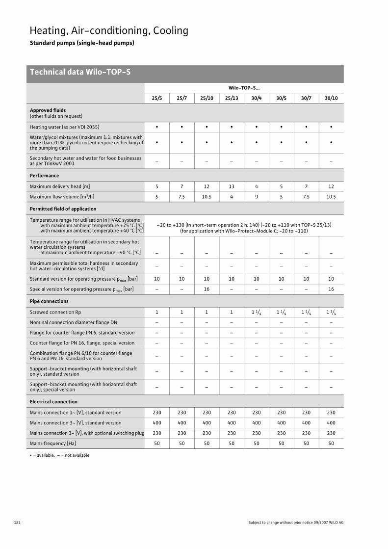
182 Subject to change without prior notice 09/2007 WILO AG
Heating, Air-conditioning, CoolingStandard pumps (single-head pumps)
Technical data Wilo-TOP-S
Wilo-TOP-S...
25/5 25/7 25/10 25/13 30/4 30/5 30/7 30/10
Approved fluids(other fluids on request)
Heating water (as per VDI 2035) • • • • • • • •Water/glycol mixtures (maximum 1:1; mixtures with more than 20 % glycol content require rechecking of the pumping data)
• • • • • • • •
Secondary hot water and water for food businesses as per TrinkwV 2001 – – – – – – – –
Performance
Maximum delivery head [m] 5 7 12 13 4 5 7 12
Maximum flow volume [m3/h] 5 7.5 10.5 4 9 5 7.5 10.5
Permitted field of application
Temperature range for utilisation in HVAC systemswith maximum ambient temperature +25 °C [°C]with maximum ambient temperature +40 °C [°C]
–20 to +130 (in short-term operation 2 h: 140) (-20 to +110 with TOP-S 25/13)(for application with Wilo-Protect-Module C: -20 to +110)
Temperature range for utilisation in secondary hot water circulation systems
at maximum ambient temperature +40 °C [°C] – – – – – – – –
Maximum permissible total hardness in secondary hot water-circulation systems [°d] – – – – – – – –
Standard version for operating pressure pmax [bar] 10 10 10 10 10 10 10 10
Special version for operating pressure pmax [bar] – – 16 – – – – 16
Pipe connections
Screwed connection Rp 1 1 1 1 1 1/4 1 1/4 1 1/4 1 1/4
Nominal connection diameter flange DN – – – – – – – –
Flange for counter flange PN 6, standard version – – – – – – – –
Counter flange for PN 16, flange, special version – – – – – – – –
Combination flange PN 6/10 for counter flange PN 6 and PN 16, standard version – – – – – – – –
Support-bracket mounting (with horizontal shaft only), standard version – – – – – – – –
Support-bracket mounting (with horizontal shaft only), special version – – – – – – – –
Electrical connection
Mains connection 1~ [V], standard version 230 230 230 230 230 230 230 230
Mains connection 3~ [V], standard version 400 400 400 400 400 400 400 400
Mains connection 3~ [V], with optional switching plug 230 230 230 230 230 230 230 230
Mains frequency [Hz] 50 50 50 50 50 50 50 50
• = available, – = not available

183
Heating, Air-conditioning, CoolingStandard pumps (single-head pumps)
Technical data Wilo-TOP-S
Wilo Catalogue A1 - 50 Hz - Circulating Pumps in Glandless Design
Hea
ting,
Air-
cond
ition
ing,
Co
olin
gSe
cond
ary
Hot W
ater
Circ
ulat
ion
Sola
r The
rmal
, Geo
ther
mal
En
ergy
Sys
tem
sSe
rvic
e/Ac
cess
orie
s, S
yste
ms
Switc
hgea
rs a
nd C
ontr
ol
Dev
ices
Pum
p M
anag
emen
t Sys
tem
s
Motor/electronics
Electromagnetic compatibility – – – – – – – –
Emitted interference EN 61000-6-3
Immunity to interference EN 61000-6-2
Power electronics – – – – – – – –
Protection class IP 44 IP 44 IP 44 IP 44 IP 44 IP 44 IP 44 IP 44
Insulation class F F F F F F F F
Materials
Pump housing Cast iron (EN-GJL-200)
Impeller
Plastic (PPE, trade
name: Noryl)
Plastic(PP - 50% GF)
Plastic (PPE, trade name Noryl)
Plastic(PP - 50% GF)
Shaft Stainless steel (X46 Cr13)
Bearing Metal-impregnated carbon
Minimum suction head at suction port [m]for the prevention of cavitation at water delivery temperature
50 °C 0.5 0.5 0.5 0.5 0.5 0.5 0.5 0.5
95 °C 5 5 5 5 5 5 5 5
110 °C 11 11 11 11 11 11 11 11
130 °C 24 24 24 24 24 24 24 24
Wilo-TOP-S...
25/5 25/7 25/10 25/13 30/4 30/5 30/7 30/10
• = available, – = not available

184 Subject to change without prior notice 09/2007 WILO AG
Heating, Air-conditioning, CoolingStandard pumps (single-head pumps)
Technical data Wilo-TOP-S
Wilo-TOP-S...
40/4 40/7 40/10 40/15 50/4 50/7 50/10 50/15
Approved fluids(other fluids on request)
Heating water (as per VDI 2035) • • • • • • • •Water/glycol mixtures (maximum 1:1; mixtures with more than 20 % glycol content require rechecking of the pumping data)
• • • • • • • •
Secondary hot water and water for food businesses as per TrinkwV 2001 – – – – – – – –
Performance
Maximum delivery head [m] 4.5 7 10 15 5 7 10 15
Maximum flow volume [m3/h] 14 16.5 21 21 23 28 32 36
Permitted field of application
Temperature range for utilisation in HVAC systemswith maximum ambient temperature +25 °C [°C]with maximum ambient temperature +40 °C [°C]
–-20 to +130 (in short-term operation 2 h: 140)
(for utilisation with Wilo-Protect-Module C: -20 to +110)
Temperature range for utilisation in secondary hot water circulation systems
at maximum ambient temperature +40 °C [°C] – – – – – – – –
Maximum permissible total hardness in secondary hot water-circulation systems [°d] – – – – – – – –
Standard version for operating pressure pmax [bar] 6/10 6/10 6/10 6/10 6/10 6/10 6/10 6/10
Special version for operating pressure pmax [bar] 16 16 16 16 16 16 16 16
Pipe connections
Screwed connection Rp – – – – – – – –
Nominal connection diameter flange DN 40 40 40 40 50 50 50 50
Flange for counter flange PN 6, standard version – – – – – – – –
Counter flange for PN 16, flange, special version – • • • • • • •Combination flange PN 6/10 for counter flange PN 6 and PN 16, standard version • • • • • • • •
Support-bracket mounting (with horizontal shaft only), standard version – – – – – – – –
Support-bracket mounting (with horizontal shaft only), special version – – – – – – – –
Electrical connection
Mains connection 1~ [V], standard version 230 230 230 230 230 230 230 –
Mains connection 3~ [V], standard version 400 400 400 400 400 400 400 400
Mains connection 3~ [V], with optional switching plug 230 230 230 230 230 230 230 230
Mains frequency [Hz] 50 50 50 50 50 50 50 50
• = available, – = not available

185
Heating, Air-conditioning, CoolingStandard pumps (single-head pumps)
Technical data Wilo-TOP-S
Wilo Catalogue A1 - 50 Hz - Circulating Pumps in Glandless Design
Hea
ting,
Air-
cond
ition
ing,
Co
olin
gSe
cond
ary
Hot W
ater
Circ
ulat
ion
Sola
r The
rmal
, Geo
ther
mal
En
ergy
Sys
tem
sSe
rvic
e/Ac
cess
orie
s, S
yste
ms
Switc
hgea
rs a
nd C
ontr
ol
Dev
ices
Pum
p M
anag
emen
t Sys
tem
s
Motor/electronics
Electromagnetic compatibility – – – – – – – –
Emitted interference EN 61000-6-3
Immunity to interference EN 61000-6-2
Power electronics – – – – – – – –
Protection class IP 44 IP 44 IP 44 IP 44 IP 44 IP 44 IP 44 IP 44
Insulation class F F F F F F F F
Materials
Pump housing Cast iron (EN-GJL-250)
Impeller Plastic (PP - 50% GF)
Shaft Stainless steel (X46 Cr13)
Bearing Metal-impregnated carbon
Minimum suction head at suction port [m]for the prevention of cavitation at water delivery temperature
50 °C 0.5 0.5 0.5 0.5 3 3 3 3
95 °C 5 5 5 5 10 10 10 10
110 °C 11 11 11 11 16 16 16 16
130 °C 24 24 24 24 29 29 29 29
Wilo-TOP-S...
40/4 40/7 40/10 40/15 50/4 50/7 50/10 50/15
• = available, – = not available
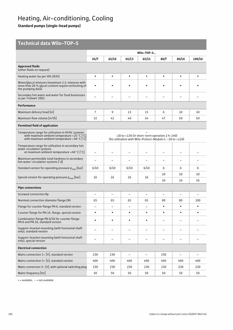
186 Subject to change without prior notice 09/2007 WILO AG
Heating, Air-conditioning, CoolingStandard pumps (single-head pumps)
Technical data Wilo-TOP-S
Wilo-TOP-S...
65/7 65/10 65/13 65/15 80/7 80/10 100/10
Approved fluids(other fluids on request)
Heating water (as per VDI 2035) • • • • • • •Water/glycol mixtures (maximum 1:1; mixtures with more than 20 % glycol content require rechecking of the pumping data)
• • • • • • •
Secondary hot water and water for food businesses as per TrinkwV 2001 – – – – – – –
Performance
Maximum delivery head [m] 7 9 13 15 6 10 10
Maximum flow volume [m3/h] 32 42 49 54 47 69 69
Permitted field of application
Temperature range for utilisation in HVAC systemswith maximum ambient temperature +25 °C [°C]with maximum ambient temperature +40 °C [°C]
–-20 to +130 (in short-term operation 2 h: 140)
(for utilisation with Wilo-Protect-Module C: -20 to +110)
Temperature range for utilisation in secondary hot water circulation systems
at maximum ambient temperature +40 °C [°C] – – – – – – –
Maximum permissible total hardness in secondary hot water-circulation systems [°d] – – – – – – –
Standard version for operating pressure pmax [bar] 6/10 6/10 6/10 6/10 6 6 6
Special version for operating pressure pmax [bar] 16 16 16 1610 10 10
16 16 16
Pipe connections
Screwed connection Rp – – – – – – –
Nominal connection diameter flange DN 65 65 65 65 80 80 100
Flange for counter flange PN 6, standard version – – – – • • •Counter flange for PN 16, flange, special version • • • • • • •Combination flange PN 6/10 for counter flange PN 6 and PN 16, standard version • • • • – – –
Support-bracket mounting (with horizontal shaft only), standard version – – – – – – –
Support-bracket mounting (with horizontal shaft only), special version – – – – – – –
Electrical connection
Mains connection 1~ [V], standard version 230 230 – – 230 – –
Mains connection 3~ [V], standard version 400 400 400 400 400 400 400
Mains connection 3~ [V], with optional switching plug 230 230 230 230 230 230 230
Mains frequency [Hz] 50 50 50 50 50 50 50
• = available, – = not available

187
Heating, Air-conditioning, CoolingStandard pumps (single-head pumps)
Technical data Wilo-TOP-S
Wilo Catalogue A1 - 50 Hz - Circulating Pumps in Glandless Design
Hea
ting,
Air-
cond
ition
ing,
Co
olin
gSe
cond
ary
Hot W
ater
Circ
ulat
ion
Sola
r The
rmal
, Geo
ther
mal
En
ergy
Sys
tem
sSe
rvic
e/Ac
cess
orie
s, S
yste
ms
Switc
hgea
rs a
nd C
ontr
ol
Dev
ices
Pum
p M
anag
emen
t Sys
tem
s
Motor/electronics
Electromagnetic compatibility – – – – – – –
Emitted interference EN 61000-6-3
Immunity to interference EN 61000-6-2
Power electronics – – – – – – –
Protection class IP 44 IP 44 IP 44 IP 44 IP 44 IP 44 IP 44
Insulation class F F F F F F F
Materials
Pump housing Cast iron (EN-GJL-250)
Impeller Plastic (PP - 50% GF)
Shaft Stainless steel (X46 Cr13)
Bearing Metal-impregnated carbon
Minimum suction head at suction port [m]for the prevention of cavitation at water delivery temperature
50 °C 3 3 3 3 3 3 3
95 °C 10 10 10 10 10 10 10
110 °C 16 16 16 16 16 16 16
130 °C 29 29 29 29 29 29 29
Wilo-TOP-S...
65/7 65/10 65/13 65/15 80/7 80/10 100/10
• = available, – = not available

188 Subject to change without prior notice 09/2007 WILO AG
Heating, Air-conditioning, CoolingStandard pumps (single-head pumps)
Pump curves Wilo-TOP-S
Wilo-TOP-S 25/5, TOP-S 30/5
AC Three-phase (DM)
Wilo-TOP-S 25/7,TOP-S 30/7
AC Three-phase (DM)
0 1 2 3 4 5 6
0 1 2 3 4 5 6 [m 3/h]
Q
[m 3/h]
150
125
100
75
50
25
0
6
5
4
3
2
1
0
Wilo-TOP-S 25/5Wilo-TOP-S 30/51~230 V - Rp1/Rp11/4
0 0,5 1 1,5
0 5 10 15 20 [lgpm]
[l/s]
min.
min.
max.
0 1 2 3
0 0,5 1 1,5 2
v
[m/s]Rp1
Rp11/4
max.
P 1[W]
H[m
]
0 0,5 1 1,5
0 5 10 15 20 [lgpm]
[l/s]0 1 2 3 4 5 6
0 1 2 3 4 5 6 [m 3/h]
Q
[m 3/h]
150
125
100
75
50
25
0
6
5
4
3
2
1
0
Wilo-TOP-S 25/5Wilo-TOP-S 30/53~400 V - Rp1/Rp11/4
min.
min.
max.
0 1 2 3
0 0,5 1 1,5 2
v
[m/s]Rp1
Rp11/4
max.
P 1[W]
H[m
]
0 1 2 3 Rp1
0 0,5 1 1,5 2
0 5 10 15 20 25
0 1 2 3 4 5 6 7
0 1 2 3 4 5 6 7
v
[m 3/h]
P1 [
W ]
H[m
]
Q
[m 3/h]
[lgpm]
200
175
150
125
100
75
50
25
0
8
7
6
5
4
3
2
1
0
[l/s]
min.
max.
max.
0 0,5 1 1,5 2 Rp11/4
[m/s]
min.
Wilo-TOP-S 25/7Wilo-TOP-S 30/71~230 V - Rp1/Rp1¼
200
175
150
125
100
75
50
25
0
0 0,5 1 1,5 2
0 5 10 15 20 25
0 1 2 3 4 5 6 7
0 1 2 3 4 5 6 7 [m 3/h]
P1 [
W]
H[m
]
Q
[m 3/h]
[lgpm]
8
7
6
5
4
3
2
1
0
[l/s]
min.
max.
min.
max.
0 1 2 3 Rp1v
0 0,5 1 1,5 2 Rp11/4
[m/s]
Wilo-TOP-S 25/7Wilo-TOP-S 30/73~400 V - Rp1/Rp1¼
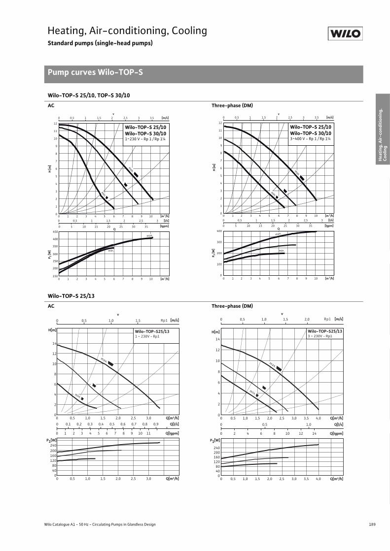
189
Heating, Air-conditioning, CoolingStandard pumps (single-head pumps)
Pump curves Wilo-TOP-S
Wilo Catalogue A1 - 50 Hz - Circulating Pumps in Glandless Design
Hea
ting,
Air-
cond
ition
ing,
Co
olin
gSe
cond
ary
Hot W
ater
Circ
ulat
ion
Sola
r The
rmal
, Geo
ther
mal
En
ergy
Sys
tem
sSe
rvic
e/Ac
cess
orie
s, S
yste
ms
Switc
hgea
rs a
nd C
ontr
ol
Dev
ices
Pum
p M
anag
emen
t Sys
tem
s
Wilo-TOP-S 25/10, TOP-S 30/10
AC Three-phase (DM)
Wilo-TOP-S 25/13
AC Three-phase (DM)
H [m
]P 1
[W]
0 0,5 1 1,5 2 2,5 3
0 5 10 15 20 25 30 35
0 1 2 3 4 5 6 7 8 9 10
0 1 2 3 4 5 6 7 8 9 10 [m 3/h]
Q
[m 3/h]
[lgpm]
150
200
12
11
10
9
8
7
6
5
4
3
2
1
0
[l/s]
min.
min.
max.
0 0,5 1 1,5 2 2,5 3 3,5v
[m/s]
250
300
350
400
450max.
Wilo-TOP-S 25/10Wilo-TOP-S 30/101~230 V - Rp 1 / Rp 1¼
H [m
]P 1
[W]
0 1 2 3 4 5 6 7 8 9 10 [m 3/h]0 0,5 1 1,5 2 2,5 3
0 5 10 15 20 25 30 35 [lgpm]
[l/s]
400
300
200
100
00 1 2 3 4 5 6 7 8 9 10 [m 3/h]
Q
min.
0 0,5 1 1,5 2 2,5 3 3,5v
[m/s]
max.
12
11
10
9
8
7
6
5
4
3
2
1
0
min.
max.
Wilo-TOP-S 25/10Wilo-TOP-S 30/103~400 V - Rp 1 / Rp 1¼
[m/s]0 0,5 1,0 1,5
Q[m³/h]0 0,5 1,0 1,5 2,0 2,5 3,0
Q[l/s]0 0,1 0,2 0,3 0,4 0,5 0,6 0,7 0,8 0,9
Q[Igpm]0 1 2 3 4 5 6 7 8 9 10 11
H[m]
0
2
4
6
8
10
12
14
Q[m³/h]0 0,5 1,0 1,5 2,0 2,5 3,0
P1[W]
04080
120160200240
Rp1
v
min.
max.
Wilo-TOP-S25/131 ~ 230V - Rp1
[m/s]0 0,5 1,0 1,5 2,0
Q[m³/h]0 0,5 1,0 1,5 2,0 2,5 3,0 3,5 4,0
Q[l/s]0 0,5 1,0
Q[Igpm]0 2 4 6 8 10 12 14
H[m]
0
2
4
6
8
10
12
14
Q[m³/h]0 0,5 1,0 1,5 2,0 2,5 3,0 3,5 4,0
P1[W]
04080
120160200240
Rp1v
Wilo-TOP-S25/133 ~ 230V - Rp1
min.
max.

190 Subject to change without prior notice 09/2007 WILO AG
Heating, Air-conditioning, CoolingStandard pumps (single-head pumps)
Pump curves Wilo-TOP-S
Wilo-TOP-S 30/4
AC Three-phase (DM)
Wilo-TOP-S 40/4
AC Three-phase (DM)
0 0,5 1 1,5 2 2,5
0 5 10 15 20 25 30
0 1 2 3 4 5 6 7 8 9
0 1 2 3 4 5 6 7 8 9 [m 3/h]
P1 [
W]
H [m
]
Q
[m 3/h]
[lgpm]
200
175
150
125
100
75
50
25
0
5
4
3
2
1
0
[l/s]
max.
min.
min.
max.
0 0,5 1 1,5 2 2,5 3v
[m/s]
Wilo-TOP-S 30/41~230 V - Rp 1¼
0 0,5 1 1,5 2 2,5
0 5 10 15 20 25 30
0 1 2 3 4 5 6 7 8 9
0 1 2 3 4 5 6 7 8 9 [m 3/h]
P1 [
W]
H [m
]
Q
[m 3/h]
[lgpm]
200
175
150
125
100
75
50
25
0
5
4
3
2
1
0
[l/s]
max.
min.
min.
0 0,5 1 1,5 2 2,5 3v
[m/s]
max.
Wilo-TOP-S 30/43~400 V - Rp 1¼
0 1 2 3 4
0 10 20 30 40 50
0 0,5 1 1,5 2 2,5
0 2 4 6 8 10 12 14
0 2 4 6 8 10 12 14
v [m/s]
Q[lgpm]
200
175
150
125
100
75
50
25
0
5
4,5
4
3,5
3
2,5
2
1,5
1
0,5
0
[l/s]
max.
min.
[m3/h]
[m3/h]
P 1[W]
H[m
]
max.
min.
Wilo-TOP-S 40/41~230 V - DN 40
0 2 4 6 8 10 12 14
Q 200
175
150
125
100
75
50
25
0
max.
0 2 4 6 8 10 12 14
5
4,5
4
3,5
3
2,5
2
1,5
1
0,5
0
0 1 2 3 4
0 10 20 30 40 50 [lgpm]
[l/s]
0 0,5 1 1,5 2 2,5 v
[m/s]
min.
P 1[W]
H[m
]
[m3/h]
[m3/h]
Wilo-TOP-S 40/43~400 V - DN 40
min.
max.

191
Heating, Air-conditioning, CoolingStandard pumps (single-head pumps)
Pump curves Wilo-TOP-S
Wilo Catalogue A1 - 50 Hz - Circulating Pumps in Glandless Design
Hea
ting,
Air-
cond
ition
ing,
Co
olin
gSe
cond
ary
Hot W
ater
Circ
ulat
ion
Sola
r The
rmal
, Geo
ther
mal
En
ergy
Sys
tem
sSe
rvic
e/Ac
cess
orie
s, S
yste
ms
Switc
hgea
rs a
nd C
ontr
ol
Dev
ices
Pum
p M
anag
emen
t Sys
tem
s
Wilo-TOP-S 40/7
AC Three-phase (DM)
Wilo-TOP-S 40/10
AC Three-phase (DM)
0 1 2 3 4
0 10 20 30 40 50
0 0,5 1 1,5 2 2,5 3
0 2 4 6 8 10 12 14 16
v
500
450
400
350
300
250
200
150
100
8
7
6
5
4
3
2
1
0
min.
max.
max.
min.
[m3/h]
0 2 4 6 8 10 12 14 16 [m3/h]
[lgpm][l/s]
[m/s]
Q
P 1[W]
H[m
]
Wilo-TOP-S 40/71~230 V - DN 40
min.
max.
0 2 4 6 8 10 12 14 16 [m3/h]
0 10 20 30 40 50 [lgpm]
0 1 2 3 4 [l/s]
0 0,5 1 1,5 2 2,5 3v
[m/s]
Q500
450
400
350
300
250
200
150
100
P 1[W]
8
7
6
5
4
3
2
1
0H
[m] max.
min.
Wilo-TOP-S 40/73~400 V - DN 40
0 2 4 6 8 10 12 14 16 [m3/h]
0 4 8 12 160
100
200
300
400
500
600
700Q
max.min.
0 0,5 1,0 1,5 2,0 2,5 3,0
0 1 2 3 4 5
v
0
2
4
6
8
10
0 4 8 12 16
max.
min.
H [m
]P 1
[W]
[m3/h]
[m3/h]
[m/s]
[l/s]
Wilo-TOP-S 40/101~230 V - DN 40
0 1 2 3 4 5
0 10 20 30 40 50 60 70
0 2 4 6 8 10 12 14 16 18
0 2 4 6 8 10 12 14 16 18
Q[lgpm]
600
500
400
300
200
100
0
12
11
10
9
8
7
6
5
4
3
2
1
0
[l/s]
max.
0 0,5 1 1,5 2 2,5 3 3,5 v
[m/s]
max.
min.
min.
[m3/h]
[m3/h]
P 1[W]
H[m
]
Wilo-TOP-S 40/103~400 V, DN 40

192 Subject to change without prior notice 09/2007 WILO AG
Heating, Air-conditioning, CoolingStandard pumps (single-head pumps)
Pump curves Wilo-TOP-S
Wilo-TOP-S 40/15
AC Three-phase (DM)
Wilo-TOP-S 50/4
AC Three-phase (DM)
2 4 8 12 16 18 Q [m³/h]
Q [l/s]
0
2
4
6
8
10
12
14
16
H [m
]
0 20 40 60 Q [Igpm]
200300400
500600700
800900
1000
0
0 1 2 3 4 5
6 10 14
2 4 60 10 12 14 16 188 Q [m³/h]
P 1 [W]
0 0,5 1,51 2,52 3,53 4,54 [m/s]v
Wilo-TOP-S 40/151~230V - DN 40
max.
min.
max.
min.
0 1 2 3 4 [m/s]
0
2
4
6
8
10
12
14
16
2,5 7,5 12,5 17,5 Q [m³/h]
H [m
]
0 1 2 3 4 5 Q [l/s]
0 20 40 60 Q [Igpm]
0
250
500
750
1000
2,5 7,5 12,5
0
0
5 10 15
5 10 15 17,5 Q [m³/h]
P 1 [W]
v
min.
Wilo-TOP-S 40/153~400 V DN 40
max.
max.
min.
0 1 2 3 4 5 6
0 25 50 75
0 0,5 1 1,5 2 2,5 3
0 5 10 15 20
0 5 10 15 20
v[m/s]
[m 3/h]
P1 [
W]
H[m
]
Q
[m 3/h]
[lgpm]
400
350
300
250
200
5
4,5
4
3,5
3
2,5
2
1,5
1
0,5
0
[l/s]
min.
max.
max.
min.
Wilo-TOP-S 50/41~230 V - DN 50
400
300
200
100
0
0 5 10 15 20
0 5 10 15 20 [m 3/h]
P1 [
W ]
H[m
]
[m 3/h]
5
4,5
4
3,5
3
2,5
2
1,5
1
0,5
0
max.
min.
max.
min.
0 1 2 3 4 5 6
0 25 50 75Q
[lgpm]
[l/s]
0 0,5 1 1,5 2 2,5 3v
[m/s]
Wilo-TOP-S 50/43~400 V - DN 50
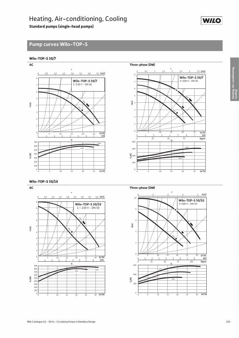
193
Heating, Air-conditioning, CoolingStandard pumps (single-head pumps)
Pump curves Wilo-TOP-S
Wilo Catalogue A1 - 50 Hz - Circulating Pumps in Glandless Design
Hea
ting,
Air-
cond
ition
ing,
Co
olin
gSe
cond
ary
Hot W
ater
Circ
ulat
ion
Sola
r The
rmal
, Geo
ther
mal
En
ergy
Sys
tem
sSe
rvic
e/Ac
cess
orie
s, S
yste
ms
Switc
hgea
rs a
nd C
ontr
ol
Dev
ices
Pum
p M
anag
emen
t Sys
tem
s
Wilo-TOP-S 50/7
AC Three-phase (DM)
Wilo-TOP-S 50/10
AC Three-phase (DM)
0
1
2
3
4
5
6
7
8
0
100
200
300
400
500
600
700
0 5 10 15 20 25
0 0,5 1,0 1,5 2,0 2,5 3,0 3,5
0 1 2 3 4 5 6 70 5 10 15 20 25
v
Q
max.
min.
max.
min.
H [m
]P 1
[W]
[m3/h]
[m3/h]
[m/s]
[l/s]
Wilo-TOP-S 50/71~230 V - DN 40
0 1 2 3 4 5 6 7
0 25 50 75
0 0,5 1 1,5 2 2,5 3 3,5
0 5 10 15 20 25
0 5 10 15 20 25
v [m/s]
Q[lgpm]
800
600
400
200
0
8
7
6
5
4
3
2
1
0
[l/s]
min.
max.
min.
max.
[m3/h]
[m3/h] P 1[W
]H
[m]
Wilo-TOP-S 50/73~400 V - DN 50
0
1
2
3
4
5
6
7
8
9
0
100
200
300
400
500
600
700
800
900
0 5 10 15 20 25 30
0 5 10 15 20 25 300 1 2 3 4 5 6 7 8
0 0,5 1,0 1,5 2,0 2,5 3,0 3,5 4,0
v
Wilo-TOP-S 50/101 ~ 230 V - DN 50
Q
max.
min.
max.min.
H [m
]P 1
[W]
[m3/h]
[m3/h]
[m/s]
[l/s]
900
600
300
0
0 5 10 15 20 25 30
0 5 10 15 20 25 30
Q
10
8
6
4
2
0
min.
0 1 2 3 4 5 6 7 8
0 25 50 75 100 [lgpm]
[l/s]
0 1 2 3 4 v
[m/s]
max.
max.
min.
[m3/h]
[m3/h]
P 1[W]
H[m
]
Wilo-TOP-S 50/103~400 V - DN 50

194 Subject to change without prior notice 09/2007 WILO AG
Heating, Air-conditioning, CoolingStandard pumps (single-head pumps)
Pump curves Wilo-TOP-S
Wilo-TOP-S 50/15
Three-phase (DM)
Wilo-TOP-S 65/7
AC Three-phase (DM)
0
2
4
6
8
10
12
14
16
0 5 10 15 20 25 30 Q [m³/h]
H [m
]
0 1 2 3 4 5 6 7 8 9 Q [l/s]
0 20 40 60 80 100 120 Q [Igpm]
0
250
500
750
1000
1250
1500
1750
0 5 10 15 20 25 30 Q [m³/h]
P 1 [W]
min.
max.
Wilo-TOP-S 50/153~400 V - DN 50
min.
max.
0
1
2
3
4
5
6
7
8
0
100
200
300
400
500
600
700
0 5 10 15 20 25 30
0 5 10 15 20 25 30
0 1 2 3 4 5 6 7 8
0 0,5 1,0 1,5 2,0
v[m/s]
[l/s]
Q
max.
min.
max.
min.
H [m
]P 1
[W]
[m3/h]
[m3/h]
Wilo-TOP-S 65/71~230 V - DN 65
0 1 2 3 4 5 6 7 8 9
0 20 40 60 80 100
0 0,5 1 1,5 2
0 5 10 15 20 25 30
0 5 10 15 20 25 30
v [m/s]
Q[lgpm]
700
600
500
400
300
200
100
0
8
7
6
5
4
3
2
1
0
[l/s]
min.
max.
min.
max.
[m3/h]
[m3/h]
P 1[W]
H[m
]
Wilo-TOP-S 65/73~400 V - DN 65

195
Heating, Air-conditioning, CoolingStandard pumps (single-head pumps)
Pump curves Wilo-TOP-S
Wilo Catalogue A1 - 50 Hz - Circulating Pumps in Glandless Design
Hea
ting,
Air-
cond
ition
ing,
Co
olin
gSe
cond
ary
Hot W
ater
Circ
ulat
ion
Sola
r The
rmal
, Geo
ther
mal
En
ergy
Sys
tem
sSe
rvic
e/Ac
cess
orie
s, S
yste
ms
Switc
hgea
rs a
nd C
ontr
ol
Dev
ices
Pum
p M
anag
emen
t Sys
tem
s
Wilo-TOP-S 65/10
AC Three-phase (DM)
Wilo-TOP-S 65/13 Wilo-TOP-S 65/15
Three-phase (DM) Three-phase (DM)
0
1
2
3
4
5
6
7
8
9
0 1 2 3 4 5 6 7 8 9 10
Q
max.
min.
max.
min.
1000
900
800
700
600
500
400
300
200
0 5 10 15 20 25 30 35
0 5 10 15 20 25 30 35
0 0,5 1 1,5 2 2,5v
[m/s]
[l/s]
[m3/h]
[m3/h]
P 1[W]
H[m
]
Wilo-TOP-S 65/101~230 V - DN 65
1000
900
800
700
600
500
400
300
200
0 2 4 6 8 10
0 20 40 60 80 100 120 140
0 0,5 1 1,5 2 2,5 3
0 5 10 15 20 25 30 35 40
0 5 10 15 20 25 30 35 40
v [m/s]
Q [lgpm]
10
9
8
7
6
5
4
3
2
1
0
[l/s]
min.
max.
min.
max.
[m3/h]
[m3/h] P 1[W
] H
[m]
Wilo-TOP-S 65/103~400 V - DN 65
0 2 4 6 8 10 12
0 20 40 60 80 100 120 140 160
0 1 2 3
0 5 10 15 20 25 30 35 40 45
0 5 10 15 20 25 30 35 40 45
v [m/s]
Q[lgpm]
1800
1600
1400
1200
1000
800
600
14
12
10
8
6
4
2
0
[l/s]
max.
min.
max.
min.
[m3/h]
[m3/h]
P 1[W]
H[m
]
Wilo-TOP-S 65/133~400 V - DN 65
1800
1600
1400
1200
1000
800
600
0 2 4 6 8 10 12 14
0 20 40 60 80 100 120 140 160 180
0 0,5 1 1,5 2 2,5 3 3,5 4
0 10 20 30 40 50
0 10 20 30 40 50
v [m/s]
Q[lgpm]
16
14
12
10
8
6
4
2
0
[l/s]
min.
max.
max.
min.
[m3/h]
[m3/h]
P 1[W]
H[m
]
Wilo-TOP-S 65/153~400 V - DN 65

196 Subject to change without prior notice 09/2007 WILO AG
Heating, Air-conditioning, CoolingStandard pumps (single-head pumps)
Pump curves Wilo-TOP-S
Wilo-TOP-S 80/7
AC Three-phase (DM)
Wilo-TOP-S 80/10 Wilo-TOP-S 100/10
Three-phase (DM) Three-phase (DM)
0
1
2
3
4
5
6
7
0 100 3 6 9 12
20 30 40 50
Q
max.
min.
max.
min.
1100
1000
900
800
700
600
500
0 0,5 1 1,5 2 2,5v
[m/s]
[l/s]
[m3/h]
0 10 20 30 40 50 [m3/h]
P 1[W]
H[m
]
Wilo-TOP-S 80/71~230 V - DN 80
0 3 6 9 12
0 50 100 150
0 0,5 1 1,5 2 2,5
0 10 20 30 40
0 10 20 30 40
v [m/s]
Q[lgpm]
800
700
600
500
400
300
7
6
5
4
3
2
1
0
[l/s]
min.
max.
max.
min.
[m3/h]
[m3/h]
P 1[W]
H[m
]
Wilo-TOP-S 80/73~400 V - DN 80
1800
1600
1400
1200
1000
800
0 3 6 9 12 15
0 50 100 150
0 0,5 1 1,5 2 2,5 3
0 10 20 30 40 50 60
0 10 20 30 40 50 60
v [m/s]
Q [lgpm]
12
11
10
9
8
7
6
5
4
3
2
1
0
[l/s]
min.
max.
min.
max.
[m3/h]
[m3/h]
P 1[W]
H[m
]
Wilo-TOP-S 80/103~400 V - DN 80
0 0,5 1 1,5 2v
[m/s]
1800
1600
1400
1200
1000
800
0 3 6 9 12 15
0 50 100 150
0 10 20 30 40 50 60
0 10 20 30 40 50 60
Q [lgpm]
12
11
10
9
8
7
6
5
4
3
2
1
0
[l/s]
min.
max.
max.
min.
[m3/h]
[m3/h]
P 1[W]
H[m
]
Wilo-TOP-S 100/103~400V - DN 100

197
Heating, Air-conditioning, CoolingStandard pumps (single-head pumps)
Terminal diagrams Wilo-TOP-S
Wilo Catalogue A1 - 50 Hz - Circulating Pumps in Glandless Design
Hea
ting,
Air-
cond
ition
ing,
Co
olin
gSe
cond
ary
Hot W
ater
Circ
ulat
ion
Sola
r The
rmal
, Geo
ther
mal
En
ergy
Sys
tem
sSe
rvic
e/Ac
cess
orie
s, S
yste
ms
Switc
hgea
rs a
nd C
ontr
ol
Dev
ices
Pum
p M
anag
emen
t Sys
tem
s
Terminal diagram A/motor protection A Terminal diagram B/motor protection B
Mains connection 1~230 V, 50 Hz Mains connection 3~400 V, 50 Hz3~230 V, 50 Hz (with optional switching plug 3~230 V)
Internal protection against unacceptably high winding temperaturesTriggering: Internal interruption of motor voltageReset: Automatic after motor has cooled down
Internal protection against unacceptably high winding temperaturesTriggering: Internal interruption of motor phaseReset: Disconnect mains voltage, allow motor to cool down,
switch mains voltage back on
Terminal diagram C/motor protection C Terminal diagram D/motor protection D
Mains connection 1~230 V, 50 Hz Mains connection 3~400 V, 50 Hz3~230 V, 50 Hz (with optional switching plug 3~230 V)
WSK = Thermal winding contactFull motor protection in all speed stages with optional Wilo-SK 602/SK 622/Protect-Module C relay or other switchgears/control devices with WSK connection optionTriggering: External tripping at switchgear/control deviceReset: Manual reset at switchgear/control device necessary
(circuit diagram with SK 602/622 see “Service/accessories”)
Full motor protection with integrated trip electronics in terminal box for all speed stagesTriggering: All-pole shutdown of motor by integrated tripping
electronicsReset: Manual reset at terminal box necessary
Load capacity of the potential-free NC contact as per VDI 3814 for the collective fault signal (SSM) 1 A, 250 V ~Function see “Pump management Wilo-Control, Planning guide”
Terminal diagram E/motor protection E
Mains connection 1~230 V, 50 HzFull motor protection with integrated trip electronics in terminal box for all speed stages.Triggering: All-pole shutdown of motor by integrated automatic
trippingReset: Manual reset at terminal box necessary
Load capacity of the potential-free NC contact as per 3814 only for collective fault signal (SSM) 1 A, 250 V~Function see “Pump management Wilo-Control, Planning guide”
L NPE
NL
L1 L2PE
L2
L3
L3L1
L NPE
NL
WSK
WSK
L1 L2 L3PE
L1 L2 L3
SSM
SSM
C2 N LPEC1
C1SSM LC2 N
SSM
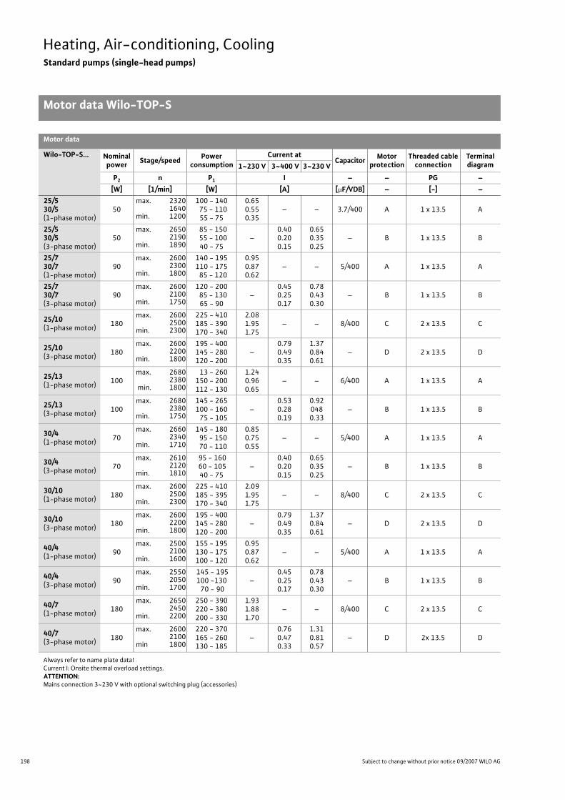
198 Subject to change without prior notice 09/2007 WILO AG
Heating, Air-conditioning, CoolingStandard pumps (single-head pumps)
Motor data Wilo-TOP-S
Motor data
Wilo-TOP-S... Nominal power Stage/speed Power
consumptionCurrent at
Capacitor Motorprotection
Threaded cableconnection
Terminaldiagram1~230 V 3~400 V 3~230 V
P2 n P1 I – – PG –[W] [1/min] [W] [A] [�F/VDB] – [-] –
25/530/5(1-phase motor)
50max. 2320
1640min. 1200
100 - 140 75 - 110
55 - 75
0.650.550.35
– – 3.7/400 A 1 x 13.5 A
25/530/5(3-phase motor)
50max. 2650
2190min. 1890
85 - 150 55 - 100
40 - 75–
0.400.200.15
0.650.350.25
– B 1 x 13.5 B
25/730/7(1-phase motor)
90max. 2600
2300min. 1800
140 - 195110 - 175 85 - 120
0.950.870.62
– – 5/400 A 1 x 13.5 A
25/730/7(3-phase motor)
90max. 2600
2100min. 1750
120 - 200 85 - 130
65 - 90–
0.450.250.17
0.780.430.30
– B 1 x 13.5 B
25/10(1-phase motor) 180
max. 26002500
min. 2300
225 - 410185 - 390170 - 340
2.081.951.75
– – 8/400 C 2 x 13.5 C
25/10(3-phase motor) 180
max. 26002200
min. 1800
195 - 400145 - 280120 - 200
–0.790.490.35
1.370.840.61
– D 2 x 13.5 D
25/13(1-phase motor) 100
max. 26802380
min. 1800
13 - 260150 - 200112 - 130
1.240.960.65
– – 6/400 A 1 x 13.5 A
25/13(3-phase motor) 100
max. 26802380
min. 1750
145 - 265100 - 160
75 - 105–
0.530.280.19
0.920480.33
– B 1 x 13.5 B
30/4(1-phase motor) 70
max. 26602340
min. 1710
145 - 180 95 - 150 70 - 110
0.850.750.55
– – 5/400 A 1 x 13.5 A
30/4(3-phase motor) 70
max. 26102120
min. 1810
95 - 160 60 - 10540 - 75
–0.400.200.15
0.650.350.25
– B 1 x 13.5 B
30/10(1-phase motor) 180
max. 26002500
min. 2300
225 - 410185 - 395170 - 340
2.091.951.75
– – 8/400 C 2 x 13.5 C
30/10(3-phase motor) 180
max. 26002200
min. 1800
195 - 400145 - 280120 - 200
–0.790.490.35
1.370.840.61
– D 2 x 13.5 D
40/4(1-phase motor) 90
max. 25002100
min. 1600
155 - 195130 - 175100 - 120
0.950.870.62
– – 5/400 A 1 x 13.5 A
40/4(3-phase motor) 90
max. 25502050
min. 1700
145 - 195100 -130 70 - 90
–0.450.250.17
0.780.430.30
– B 1 x 13.5 B
40/7(1-phase motor) 180
max. 26502450
min. 2200
250 - 390220 - 380200 - 330
1.931.881.70
– – 8/400 C 2 x 13.5 C
40/7(3-phase motor) 180
max. 26002100
min 1800
220 - 370165 - 260130 - 185
–0.760.470.33
1.310.810.57
– D 2x 13.5 D
Always refer to name plate data!Current I: Onsite thermal overload settings.ATTENTION:Mains connection 3~230 V with optional switching plug (accessories)
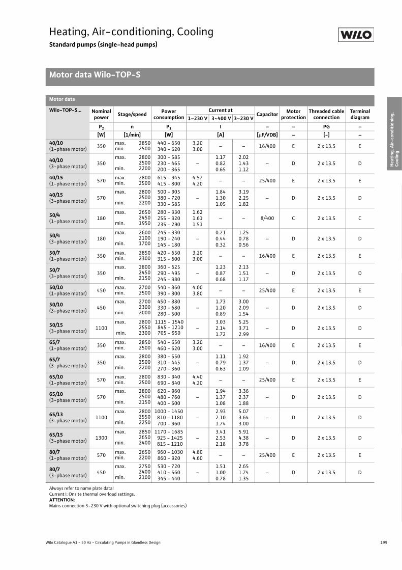
199
Heating, Air-conditioning, CoolingStandard pumps (single-head pumps)
Motor data Wilo-TOP-S
Wilo Catalogue A1 - 50 Hz - Circulating Pumps in Glandless Design
Hea
ting,
Air-
cond
ition
ing,
Co
olin
gSe
cond
ary
Hot W
ater
Circ
ulat
ion
Sola
r The
rmal
, Geo
ther
mal
En
ergy
Sys
tem
sSe
rvic
e/Ac
cess
orie
s, S
yste
ms
Switc
hgea
rs a
nd C
ontr
ol
Dev
ices
Pum
p M
anag
emen
t Sys
tem
s
40/10(1-phase motor) 350 max. 2850
min. 2500440 - 650340 - 620
3.203.00 – – 16/400 E 2 x 13.5 E
40/10(3-phase motor) 350
max. 28002500
min. 2200
300 - 585230 - 465200 - 365
–1.170.820.65
2.021.431.12
– D 2 x 13.5 D
40/15(1-phase motor) 570 max. 2800
min. 2500615 - 945415 - 800
4.574.20 – – 25/400 E 2 x 13.5 E
40/15(3-phase motor) 570
max. 28002500
min. 2200
500 - 905380 - 720330 - 585
–1.841.301.05
3.192.251.82
– D 2 x 13.5 D
50/4(1-phase motor) 180
max. 26502450
min. 1950
280 - 330255 - 320235 - 290
1.621.611.51
– – 8/400 C 2 x 13.5 C
50/4(3-phase motor) 180
max. 2600 2100
min. 1700
245 - 330190 - 240145 - 180
–0.710.440.32
1.250.780.56
– D 2 x 13.5 D
50/7(1-phase motor) 350 max. 2850
min. 2300420 - 650315 - 600
3.203.00 – – 16/400 E 2 x 13.5 E
50/7(3-phase motor) 350
max. 28002450
min. 2150
360 - 625290 - 495245 - 380
–1.230.870.68
2.131.511.17
– D 2 x 13.5 D
50/10(1-phase motor) 450 max. 2700
min. 2500540 - 860390 - 800
4.003.80 – – 25/400 E 2 x 13.5 E
50/10(3-phase motor) 450
max. 27002300
min. 2000
450 - 880330 - 680280 - 500
–1.731.200.89
3.002.091.54
– D 2 x 13.5 D
50/15(3-phase motor) 1100
max. 28002550
min. 2300
1115 - 1540845 - 1210705 - 950
–3.032.141.72
5.253.712.99
– D 2 x 13.5 D
65/7(1-phase motor) 350 max. 2850
min. 2500540 - 650460 - 620
3.203.00 – – 16/400 E 2 x 13.5 E
65/7(3-phase motor) 350
max. 28002500
min. 2200
380 - 550310 - 445270 - 360
–1.110.790.63
1.921.371.09
– D 2 x 13.5 D
65/10(1-phase motor) 570 max. 2800
min. 2500830 - 940690 - 840
4.404.20 – – 25/400 E 2 x 13.5 E
65/10(3-phase motor) 570
max. 28002500
min. 2150
620 - 960480 - 760400 - 600
–1.941.371.08
3.362.371.88
– D 2 x 13.5 D
65/13(3-phase motor) 1100
max. 28002550
min. 2250
1000 - 1450 810 - 1180
700 - 960–
2.932.101.74
5.073.643.00
– D 2 x 13.5 D
65/15(3-phase motor) 1300
max. 28502650
min. 2400
1170 - 1685 925 - 1425 815 - 1210
–3.412.532.18
5.914.383.78
– D 2 x 13.5 D
80/7(1-phase motor) 570 max. 2650
min. 2200960 - 1030860 - 920
4.804.60 – – 25/400 E 2 x 13.5 E
80/7(3-phase motor) 450
max. 27502400
min. 2100
530 - 720410 - 560345 - 440
–1.511.000.78
2.651.741.35
– D 2 x 13.5 D
Motor data
Wilo-TOP-S... Nominal power Stage/speed Power
consumptionCurrent at
Capacitor Motorprotection
Threaded cableconnection
Terminaldiagram1~230 V 3~400 V 3~230 V
P2 n P1 I – – PG –[W] [1/min] [W] [A] [�F/VDB] – [-] –
Always refer to name plate data!Current I: Onsite thermal overload settings.ATTENTION:Mains connection 3~230 V with optional switching plug (accessories)
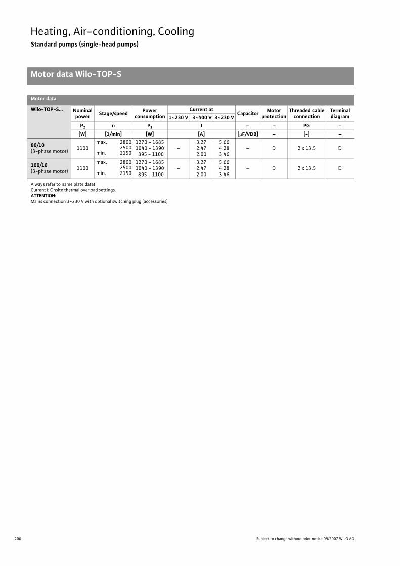
200 Subject to change without prior notice 09/2007 WILO AG
Heating, Air-conditioning, CoolingStandard pumps (single-head pumps)
Motor data Wilo-TOP-S
80/10(3-phase motor) 1100
max. 28002500
min. 2150
1270 - 16851040 - 1390 895 - 1100
–3.272.472.00
5.664.283.46
– D 2 x 13.5 D
100/10(3-phase motor) 1100
max. 28002500
min. 2150
1270 - 16851040 - 1390 895 - 1100
–3.272.472.00
5.664.283.46
– D 2 x 13.5 D
Motor data
Wilo-TOP-S... Nominal power Stage/speed Power
consumptionCurrent at
Capacitor Motorprotection
Threaded cableconnection
Terminaldiagram1~230 V 3~400 V 3~230 V
P2 n P1 I – – PG –[W] [1/min] [W] [A] [�F/VDB] – [-] –
Always refer to name plate data!Current I: Onsite thermal overload settings.ATTENTION:Mains connection 3~230 V with optional switching plug (accessories)

201
Heating, Air-conditioning, CoolingStandard pumps (single-head pumps)
Dimensions, weights Wilo-TOP-S
Wilo Catalogue A1 - 50 Hz - Circulating Pumps in Glandless Design
Hea
ting,
Air-
cond
ition
ing,
Co
olin
gSe
cond
ary
Hot W
ater
Circ
ulat
ion
Sola
r The
rmal
, Geo
ther
mal
En
ergy
Sys
tem
sSe
rvic
e/Ac
cess
orie
s, S
yste
ms
Switc
hgea
rs a
nd C
ontr
ol
Dev
ices
Pum
p M
anag
emen
t Sys
tem
s
Dimension drawing A Dimension drawing B
Permitted installation positions, see Planning guide Permitted installation positions, see Planning guide
Dimension drawing C Dimension drawing D
Permitted installation positions, see Planning guide Permitted installation positions, see Planning guide
Dimension drawing E Dimension drawing F Dimension drawing G
Permitted installation positions, see Planning guide
Pg
Rp
b1 b2
b3 b3
G
l 0
l 2a3
a2
a1
l 1b4 b5
Pg Pg
Rp
b1 b2
b3 b3
G
l 0
l 2
a3
a2
a1
l 1
b4 b5
Pg
l 0
l 2
b1
b4 b5
b2
b3 b3
R 1/8 a2
a1a3
l 1
PgPg
l 0
l 2
b1 b2
b3 b3
R 1/8
R 1 / 8
a2
a1a3
b4 b5
l 1
Pg Pg
b1 b2
b3 b3
R 1/8
R 1/8
l 0
l 2
a2
a1a3
l 1
b4 b5 Ø D
n x Ø d
Ø k
DN
L2Ø k Ø d
L 1
1
n x Ø d 2 n x Ø d
Ø D Ø k
DN
Ø d
L

202 Subject to change without prior notice 09/2007 WILO AG
Heating, Air-conditioning, CoolingStandard pumps (single-head pumps)
Dimensions, weights Wilo-TOP-S
Dimensions, weights
Wilo-TOP-S... Pipe con-nection/nominal diameter
Thread Pump dimensions Weightabout
Dimension drawing
[Rp/DN] G I0 I2 a1 a2 a3 l1 b1 b2 b3 b4 b5 PN 6/10 –– – [mm] [kg] –
25/5 Rp 1 G 11 /2 180 92 150 40 65 90 50 52 88 60 44 4.5 A
25/7 Rp 1 G 1 1/2 180 92 165 34 56 90 66 56 80 60 44 5.0 A
25/10 Rp 1 G 1 1/2 180 102 172 45 68 90 69 68 92 66 66 6.3 B
25/13 Rp 1 G 1 1/2 180 92 156 30 57 90 68 64 89 60 44 5.2 A
30/4 Rp 11/4 G 2 180 92 156 50 65 90 53 65 88 60 44 5.0 A
30/5 Rp 11/4 G 2 180 92 150 40 65 90 50 52 88 60 44 4.5 A
30/7 Rp 11/4 G 2 180 92 172 34 64 90 66 57 88 60 44 5.0 A
30/10 Rp 11/4 G 2 180 102 172 45 68 90 69 68 92 66 66 6.3 B
40/4 DN 40 – 220 102 178 54 76 110 83 60 103 66 66 9.5 C
40/7 DN 40 – 250 102 193 46 72 125 78 62 97 66 66 11.0 D
40/10 DN 40 – 250 109 216 58 88 125 90 79 121 66 66 14.0 D/E
40/15 DN 40 – 250 119 258 55 83 125 99 86 135 66 66 20.6 D/E
50/4 DN 50 – 240 102 199 52 80 120 93 64 112 66 66 13.0 D
50/7 DN 50 – 280 109 224 65 82 140 91 77 119 66 66 16.0 D/E
50/10 DN 50 – 280 109 222 70 91 140 101 86 123 66 66 17.0 D/E
50/15 DN 50 – 340 119 242 81 113 170 105 90 137 66 66 25.0 D
65/7 DN 65 – 280 109 234 74 97 140 111 86 124 66 66 18.5 D/E
65/10 DN 65 – 340 119 253 80 100 170 118 98 136 66 66 23.5 D/E
65/13 DN 65 – 340 119 253 80 100 170 118 98 136 66 66 25.5 D
65/15 DN 65 – 340 119 283 80 100 170 118 98 136 66 66 29.0 D
80/7 (1~) DN 80 – 360 109 258 96 130 180 101 87 149 66 66 28.0 E
80/7 (3~) DN 80 – 360 119 227 96 130 180 111 87 135 66 66 26 D
80/10 DN 80 – 360 119 258 95 130 180 135 108 159 66 66 28/30 D
100/10 DN 100 – 360 119 258 95 130 180 135 108 159 66 66 28.5/30.5 D

203
Heating, Air-conditioning, CoolingStandard pumps (single-head pumps)
Dimensions, weights Wilo-TOP-S
Wilo Catalogue A1 - 50 Hz - Circulating Pumps in Glandless Design
Hea
ting,
Air-
cond
ition
ing,
Co
olin
gSe
cond
ary
Hot W
ater
Circ
ulat
ion
Sola
r The
rmal
, Geo
ther
mal
En
ergy
Sys
tem
sSe
rvic
e/Ac
cess
orie
s, S
yste
ms
Switc
hgea
rs a
nd C
ontr
ol
Dev
ices
Pum
p M
anag
emen
t Sys
tem
s
Flange dimensions
Wilo-TOP-S... Flange Nominal diameter Pump flange dimensions Dimension
drawing
– DN Ø D Ø d Ø kØ kL1/kL2
n x Ø dLn x Ø dL1/dL2
–
– – [mm] [pcs. x mm] –40/440/740/10
Combination flange 6/10(flange PN 16, as per DIN 2533) 40 150 88 100/110 4 x 14/19 F
40/15 Combination flange PN 6/10(flange PN 16, as per EN 1092-2 40 150 84 100/110 4 x 14/19 F
50/450/750/10
Combination flange PN 6/10(flange PN 16, as per DIN 2533) 50 165 102 110/125 4 x 14/19 F
50/15 Combination flange PN 6/10(flange PN 16, as per EN 1092-2) 50 165 99 110/125 4 x 14/19 F
65/765/1065/1365/15
Combination flange 6/10(flange PN 16, as per DIN 2533)
65 185 122 130/145 4 x 14/19 F
80/7 (3~)
Flange PN 6(designed to PN 16,as per EN 1092-2)
80 200 132 150 4 x 19 G
Flange PN 16 (as per EN 1092-2) 80 200 132 160 8 x 19 G
80/7 (1~)80/10
Flange PN 6 (as per DIN 2531,drilled as per EN 1092-2)
80 190 128 150 4 x 19 G
Flange PN 16(as per DIN 2533,drilled as per EN 1092-2)
80 200 138 160 8 x 19 G
100/10
Flange PN 6 (as per DIN 2531,drilled as per EN 1092-2)
100 210 148 170 4 x 19 G
Flange PN 16(as per DIN 2533,drilled as per EN 1092-2)
100 220 158 180 8 x 19 G
n = No. of bolt holes

204 Subject to change without prior notice 09/2007 WILO AG
Heating, Air-conditioning, CoolingStandard pumps (single-head pumps)
Series description Wilo-TOP-D
Wilo-TOP-D
ConstructionGlandless circulating pump with screwed connection or flange con-nection. Preselectable speed stages for power adjustment
ApplicationHot-water heating systems for all systems, air-conditioning systems, closed cooling circuits, industrial circulating systems
Type keyExample: Wilo-TOP-D 40TOP-D Standard pump (screw-end or flange-end pump)40 Nominal connection width
Options• Versions for special voltages on request
Special features/product advantages• For installations with low pipe network resistances, applicable in
heating systems and in cooling/air-conditioning systems from -20 °C to +130 °C
• Universal utilisation for different mains operations:- 3~400 V as standard connection- 3~230 V with modification of the terminal allocation- 1~230 V with utilisation of a capacitor (accessories)
• Pump housing with cataphoretic (KTL) coating for the prevention of corrosion from condensation formation
• With thermal insulation as standard• Easy installation using combination flange PN 6/PN 10
(for DN 40 - DN 65)• Cable feed to terminal box possible on both sides (starting with P1 = 95 W)
possible with integrated strain-relief device• Protection class IP 44
ATTENTION:For EEI classification for each pump model see Chapter “Planning guide”, Table on page 20.
Q[m³/h]1,2 1,6 2,0 4 8 12 16 20 24 32 40
H[m]
0
0,4
0,8
1,2
1,6
2,0
Wilo-TOP-D
D100
D80
D65
D50D40
D30

205
Heating, Air-conditioning, CoolingStandard pumps (single-head pumps)
Series description Wilo-TOP-D
Wilo Catalogue A1 - 50 Hz - Circulating Pumps in Glandless Design
Hea
ting,
Air-
cond
ition
ing,
Co
olin
gSe
cond
ary
Hot W
ater
Circ
ulat
ion
Sola
r The
rmal
, Geo
ther
mal
En
ergy
Sys
tem
sSe
rvic
e/Ac
cess
orie
s, S
yste
ms
Switc
hgea
rs a
nd C
ontr
ol
Dev
ices
Pum
p M
anag
emen
t Sys
tem
s
Equipment/function
Manual functions• Setting the speed stages: 1 speed stage
Signal and display functions• Thermal winding contact (WSK, potential-free NC contact)
for TOP-D 65 to TOP-D 125• Direction-of-rotation control lamp
Equipment/scope of delivery• Cable feed possible from both sides with TOP-D 65 to TOP 125• Blocking-current proof motor (only with TOP-D 30, 40, 50)• Including seals for threaded connection (loose)• Including installation and operating instructions• Including thermal insulation• Including washers for flange bolts
(for nominal connection widths DN 32 - DN 65)
Accessories• Screwed connections with screw thread• Capacitor for AC operation 1~230 V• Condenser switchbox Wilo-SK-C2• Wilo relay SK 602
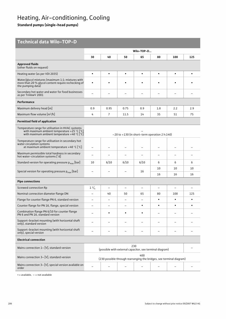
206 Subject to change without prior notice 09/2007 WILO AG
Heating, Air-conditioning, CoolingStandard pumps (single-head pumps)
Technical data Wilo-TOP-D
Wilo-TOP-D...
30 40 50 65 80 100 125
Approved fluids(other fluids on request)
Heating water (as per VDI 2035) • • • • • • •Water/glycol mixtures (maximum 1:1; mixtures with more than 20 % glycol content require rechecking of the pumping data)
• • • • • • •
Secondary hot water and water for food businesses as per TrinkwV 2001 – – – – – – –
Performance
Maximum delivery head [m] 0.9 0.95 0.75 0.9 1.8 2.2 2.9
Maximum flow volume [m3/h] 4 7 11.5 14 35 51 75
Permitted field of application
Temperature range for utilisation in HVAC systemswith maximum ambient temperature +25 °C [°C]with maximum ambient temperature +40 °C [°C]
––20 to +130 (in short-term operation 2 h:140)
Temperature range for utilisation in secondary hot water circulation systems
at maximum ambient temperature +40 °C [°C] – – – – – – –
Maximum permissible total hardness in secondary hot water-circulation systems [°d] – – – – – – –
Standard version for operating pressure pmax [bar] 10 6/10 6/10 6/10 6 6 6
Special version for operating pressure pmax [bar] – – – 1610 10 10
16 16 16
Pipe connections
Screwed connection Rp 1 1/4 – – – – – –
Nominal connection diameter flange DN – 40 50 65 80 100 125
Flange for counter flange PN 6, standard version – – – – • • •Counter flange for PN 16, flange, special version – – – • • • •Combination flange PN 6/10 for counter flange PN 6 and PN 16, standard version – • • • – – –
Support-bracket mounting (with horizontal shaft only), standard version – – – – – – –
Support-bracket mounting (with horizontal shaft only), special version – – – – – – –
Electrical connection
Mains connection 1~ [V], standard version 230 (possible with external capacitor, see terminal diagram) –
Mains connection 3~ [V], standard version 400(230 possible through rearranging the bridges, see terminal diagram)
Mains connection 3~ [V], special version available on order – – – – – – –
• = available, – = not available

207
Heating, Air-conditioning, CoolingStandard pumps (single-head pumps)
Technical data Wilo-TOP-D
Wilo Catalogue A1 - 50 Hz - Circulating Pumps in Glandless Design
Hea
ting,
Air-
cond
ition
ing,
Co
olin
gSe
cond
ary
Hot W
ater
Circ
ulat
ion
Sola
r The
rmal
, Geo
ther
mal
En
ergy
Sys
tem
sSe
rvic
e/Ac
cess
orie
s, S
yste
ms
Switc
hgea
rs a
nd C
ontr
ol
Dev
ices
Pum
p M
anag
emen
t Sys
tem
s
Electrical connection (continued)
Mains connection 3~ [V], with optional switching plug – – – – – – –
Mains frequency [Hz] 50 50 50 50 50 50 50
Motor/electronics
Electromagnetic compatibility – – – – – – –
Emitted interference EN 61000-6-3
Immunity to interference EN 61000-6-2
Power electronics – – – – – – –
Protection class IP 44 IP 44 IP 44 IP 44 IP 44 IP 44 IP 44
Insulation class F F F F F F F
Materials
Pump housingCast iron (EN-GJL-
200)Cast iron (EN-GJL-250)
Impeller Plastic (PP - 50% GF)
Shaft Stainless steel (X46 Cr13)
Bearing Metal-impregnated carbon
Minimum suction head at suction port [m]for the prevention of cavitation at water delivery temperature
50 °C 0.5 0.5 0.5 0.5 0.5 0.5 0.5
95 °C 2 2 2 2 3 3 3
110 °C 8 8 8 8 9 9 9
130 °C 21 21 21 21 22 22 22
Wilo-TOP-D...
30 40 50 65 80 100 125
• = available, – = not available

208 Subject to change without prior notice 09/2007 WILO AG
Heating, Air-conditioning, CoolingStandard pumps (single-head pumps)
Pump curves Wilo-TOP-D
Wilo-TOP-D 30 Wilo-TOP-D 40
Wilo-TOP-D 50 Wilo-TOP-D 65
0,6
0,7
0,8
0,5
0,4
0,3
0,2
0,1
0
55
60
70
65
75
0,9
0 1 2 3 40 0,5 1
0 10
0 0,5 1
5
v [m/s]
Wilo-TOP-D 30Rp 1 1/4
Q
[l/s]
[lgpm]
3 ~1 ~
0 1 2 3 4 [m3/h]
P 1[W]
H[m
]
[m3/h]
1,0
0,9
0,8
0,7
0,6
0,5
0,4
0,3
0,2
0,1
1 3 5 620
40 7
60
75
69
72
66
63
1,50,5
25155
0 0,5 1
20100
210
v [m/s]
Wilo-TOP-D 40DN 40
Q
[l/s]
[lgpm]
1 3 5 62 40 7
3 ~1 ~
[m3/h]
P 1[W]
H[m
]
[m3/h]
70
75
85
80
90
65
0 80
4 1062
0,1
0,2
0,3
0,4
0,5
0,6
0,7
0,8
0,9
0 0,5 1
0
0
1 2 3
10 20 30
v [m/s]
Wilo-TOP-D 50DN 50
Q
[l/s]
[lgpm]
0 84 1062
3 ~1 ~
[m3/h]
P 1[W]
H[m
]
[m3/h]
0,9
0,8
0,7
0,6
0,5
0,4
0,3
0,2
110
100
90
1412108642
80
0,1
00
1
0 1
0 20
0 0,5
2 3 4
40
v [m/s]
Wilo-TOP-D 65DN 65
Q
[l/s]
[lgpm]
14121086420
3 ~1 ~
[m3/h]
P 1[W]
H[m
]
[m3/h]

209
Heating, Air-conditioning, CoolingStandard pumps (single-head pumps)
Pump curves Wilo-TOP-D
Wilo Catalogue A1 - 50 Hz - Circulating Pumps in Glandless Design
Hea
ting,
Air-
cond
ition
ing,
Co
olin
gSe
cond
ary
Hot W
ater
Circ
ulat
ion
Sola
r The
rmal
, Geo
ther
mal
En
ergy
Sys
tem
sSe
rvic
e/Ac
cess
orie
s, S
yste
ms
Switc
hgea
rs a
nd C
ontr
ol
Dev
ices
Pum
p M
anag
emen
t Sys
tem
s
Wilo-TOP-D 80 Wilo-TOP-D 100
Wilo-TOP-D 125
2,0
1,8
1,6
1,4
1,2
1,0
0,8
0,6
0,4
220
200
180
3530252015105
160
0,2
00
10 0,5v
[m/s]
Wilo-TOP-D 80DN 80
[m3/h]
P1 [
W]
H [m
]
Q
[l/s]
[lgpm]
35302520151050
valid for 3 ~and for 1 ~
806040 12020
10842
100
60
0
1,5
[m3/h]
0 [m/s]v
0
0,5
1
1,5
2
2.5
0 10 20 30 40 50 Q [m³/h]H
[m]
0 2 4 6 8 10 12 14 Q [l/s]
0 20 40 60 80 100 120 140 160 180 Q [Igpm]
300
200
400
0 10 20 30 40 50 Q [m³/h]
P 1 [W
]
0,2 0,4 0,6 0,8 1,0 1,2 1,4 1,6 1,8
Wilo-TOP-D 100DN 100
gültig für 3~und für 1~
[m/s]0,0
0 20 40 60 80
0 20 40 60 80
0 5 10 15 20 25
0 50 100 150 200 250 300
0,4 0,8 1,2 1,6 2,0
Q[m³/h]
Q[l/s]
Q[Igpm]
H[m]
0,0
0,5
1,0
1,5
0,0
0,2
0,4
2,0
2,5
3,0
Q[m³/h]
P1[kW]
Wilo-TOP-D 125DN 125
gültig für 3~und für 1~
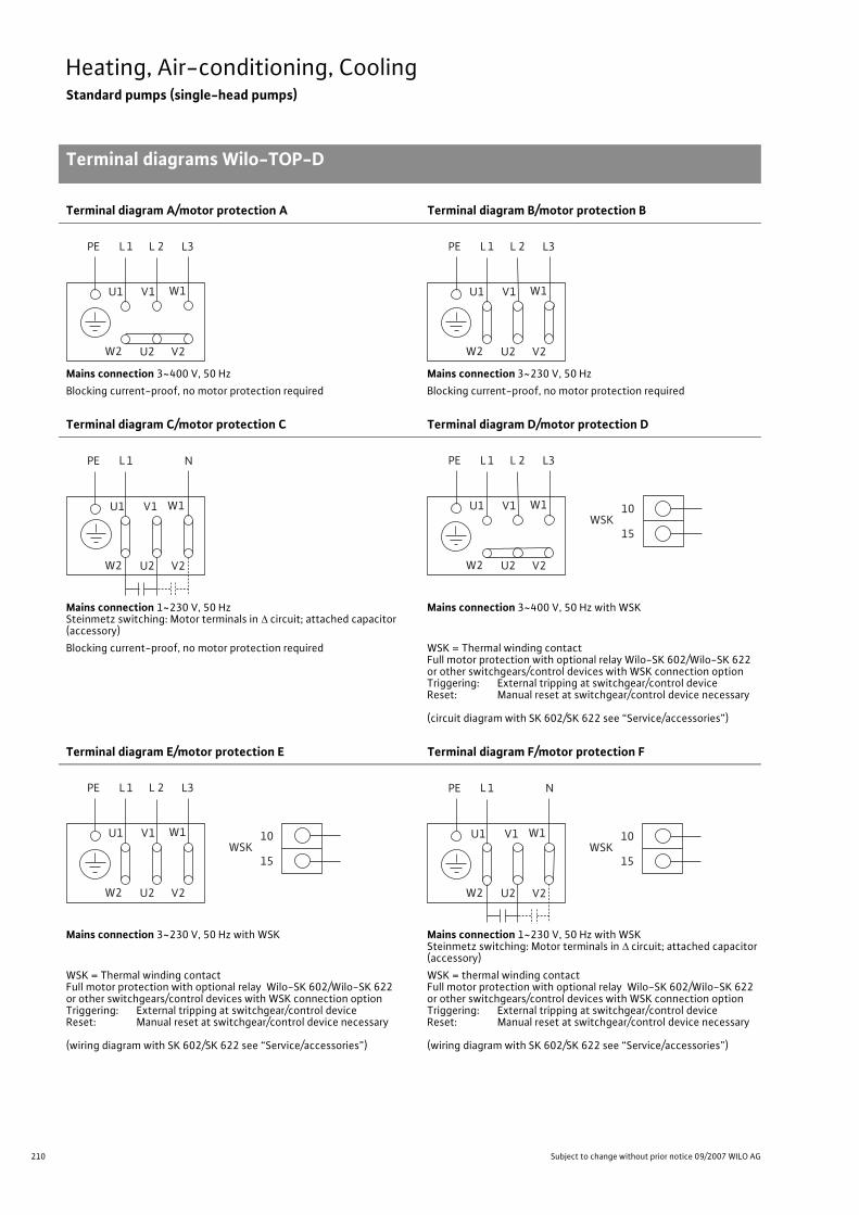
210 Subject to change without prior notice 09/2007 WILO AG
Heating, Air-conditioning, CoolingStandard pumps (single-head pumps)
Terminal diagrams Wilo-TOP-D
Terminal diagram A/motor protection A Terminal diagram B/motor protection B
Mains connection 3~400 V, 50 Hz Mains connection 3~230 V, 50 HzBlocking current-proof, no motor protection required Blocking current-proof, no motor protection required
Terminal diagram C/motor protection C Terminal diagram D/motor protection D
Mains connection 1~230 V, 50 HzSteinmetz switching: Motor terminals in � circuit; attached capacitor (accessory)
Mains connection 3~400 V, 50 Hz with WSK
Blocking current-proof, no motor protection required WSK = Thermal winding contactFull motor protection with optional relay Wilo-SK 602/Wilo-SK 622 or other switchgears/control devices with WSK connection optionTriggering: External tripping at switchgear/control deviceReset: Manual reset at switchgear/control device necessary
(circuit diagram with SK 602/SK 622 see “Service/accessories”)
Terminal diagram E/motor protection E Terminal diagram F/motor protection F
Mains connection 3~230 V, 50 Hz with WSK Mains connection 1~230 V, 50 Hz with WSKSteinmetz switching: Motor terminals in � circuit; attached capacitor (accessory)
WSK = Thermal winding contactFull motor protection with optional relay Wilo-SK 602/Wilo-SK 622 or other switchgears/control devices with WSK connection optionTriggering: External tripping at switchgear/control deviceReset: Manual reset at switchgear/control device necessary
(wiring diagram with SK 602/SK 622 see “Service/accessories”)
WSK = thermal winding contactFull motor protection with optional relay Wilo-SK 602/Wilo-SK 622 or other switchgears/control devices with WSK connection optionTriggering: External tripping at switchgear/control deviceReset: Manual reset at switchgear/control device necessary
(wiring diagram with SK 602/SK 622 see “Service/accessories”)
L 1 L3PE
W2 U2 V2
U1 V1 W1
L 2 L 1 L3PE
W2 U2 V2
U1 V1 W1
L 2
L 1 NPE
W2 U2 V2
U1 V1 W1
L 1 L3PE
W2 U2 V2
U1 V1 W1
L 2
10
15WSK
L 1 L3PE
W2 U2 V2
U1 V1 W1
L 2
10
15WSK
L 1 NPE
W2 U2 V2
U1 V1 W1 10
15WSK

211
Heating, Air-conditioning, CoolingStandard pumps (single-head pumps)
Motor data Wilo-TOP-D
Wilo Catalogue A1 - 50 Hz - Circulating Pumps in Glandless Design
Hea
ting,
Air-
cond
ition
ing,
Co
olin
gSe
cond
ary
Hot W
ater
Circ
ulat
ion
Sola
r The
rmal
, Geo
ther
mal
En
ergy
Sys
tem
sSe
rvic
e/Ac
cess
orie
s, S
yste
ms
Switc
hgea
rs a
nd C
ontr
ol
Dev
ices
Pum
p M
anag
emen
t Sys
tem
s
Motor data
Wilo-TOP-D... Nominalpower
Stage/speed
Power consumption
Current atCapacitor Motor
protection
Threaded cable con-
nection
Terminal diagram1~230 V 3~400 V 3~230 V
P2 n P1 I – – PG –[W] [1/min] [W] [A] [�F/VDB] – [-] –
30(AC connection) 20 1350 72 - 75 0.40 – – 5/240
not necessary (blocking cur-
rent-proof)
1 x 91 x 13.5 C
30(3-phase motor, 4-pole)
20 1350 58 - 65 – 0.20 0.35 –not necessary (blocking cur-
rent-proof)
1 x 91 x 13.5 A, B
40(AC connection) 20 1300 72 - 74 0.37 – – 5/240
not necessary (blocking cur-
rent-proof)
1 x 91 x 13.5 C
40(3-phase motor, 4-pole)
20 1300 63 - 70 – 0.20 0.35 –not necessary (blocking cur-
rent-proof)
1 x 91 x 13.5 A, B
50(AC connection) 20 1150 77 - 81 0.40 – – 5/240
not necessary (blocking cur-
rent-proof)
1 x 91 x 13.5 C
50(3-phase motor, 4-pole)
20 1150 73 - 86 – 0.20 0.35 –not necessary (blocking cur-
rent-proof)
1 x 91 x 13.5 A, B
65(AC connection) 60 1350 83 - 98 0.57 – – 6/240 F 1 x 9
2 x 13.5 F
65(3-phase motor, 4-pole)
60 1350 83 - 103 – 0.35 0.60 – D, E 1 x 92 x 13.5 D, E
80(AC connection) 120 1400 185 - 210 1.20 – – 14/280 F 1 x 9
2 x 13.5 F
80(3-phase motor, 4-pole)
120 1400 185 - 210 – 0.64 1.11 – D, E 1 x 92 x 13.5 D, E
100(AC connection) 220 1350 325 - 360 1.78 – – 20/400 F 1 x 9
2 x 13.5 F
100(3-phase motor, 4-pole)
220 1350 325 - 360 – 0.88 1.53 – D, E 1 x 92 x 13.5 D, E
125(3-phase motor, 4-pole)
320 1260 440-550 – 1.22 2.11 – D, E 1 x 92 x 13.5 D, E
Always refer to name plate data! Current I: Onsite thermal overload settings.
Note on AC connection:3-phase motor in Steinmetz switching
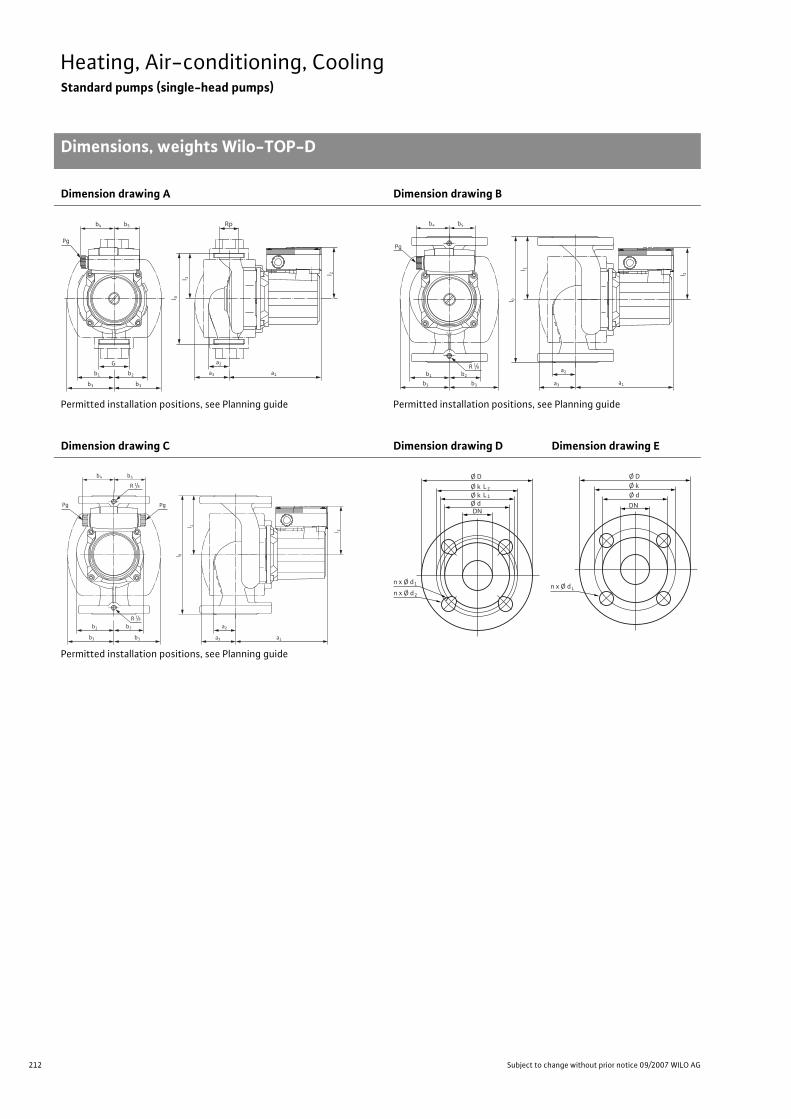
212 Subject to change without prior notice 09/2007 WILO AG
Heating, Air-conditioning, CoolingStandard pumps (single-head pumps)
Dimensions, weights Wilo-TOP-D
Dimension drawing A Dimension drawing B
Permitted installation positions, see Planning guide Permitted installation positions, see Planning guide
Dimension drawing C Dimension drawing D Dimension drawing E
Permitted installation positions, see Planning guide
Pg
Rp
b1 b2
b3 b3
G
l 0
l 2
a3
a2
a1
l 1
b4 b5
Pg
l 0
l 2
b1
b4 b5
b2
b3 b3
R 1/8 a2
a1a3
l 1
PgPg
l 0
l 2
b1 b2
b3 b3
R 1/8
R 1 / 8
a2
a1a3
b4 b5
l 1
Ø D
n x Ø d
Ø k
DN
L2Ø k Ø d
L 1
1
n x Ø d 2n x Ø d
Ø D Ø k
DN
Ø d
L

213
Heating, Air-conditioning, CoolingStandard pumps (single-head pumps)
Dimensions, weights Wilo-TOP-D
Wilo Catalogue A1 - 50 Hz - Circulating Pumps in Glandless Design
Hea
ting,
Air-
cond
ition
ing,
Co
olin
gSe
cond
ary
Hot W
ater
Circ
ulat
ion
Sola
r The
rmal
, Geo
ther
mal
En
ergy
Sys
tem
sSe
rvic
e/Ac
cess
orie
s, S
yste
ms
Switc
hgea
rs a
nd C
ontr
ol
Dev
ices
Pum
p M
anag
emen
t Sys
tem
s
Dimensions, weights
Wilo-TOP-D... Pipe con-nection/nominal diameter
Thread Pump dimensions Weightabout
Dimensiondrawing
[Rp/DN] G I0 l1 l2 a1 a2 a3 b1 b2 b3 b4 b5 PN6/10 –– [mm] [kg] –
30 Rp 11/4 G 2 180 90 92 172 34 64 66 57 88 60 44 5.0 A
40 DN 40 – 220 110 92 178 54 76 83 60 103 60 44 9.5 B
50 DN 50 – 240 120 92 185 51 80 93 57 112 60 44 11.0 B
65 DN 65 – 280 140 101 199 52 80 93 64 112 66 66 16.0 C
80 DN 80 – 330 165 108 246 86 117 145 92 167 66 66 25.5 C
100 DN 100 – 380 190 119 279 89 120 159 115 182 66 66 34.5 C
125 DN 125 – 450 225 119 290 96 127 183 132 210 66 66 46.0 C
Flange dimensions
Wilo-TOP-D... Flange Nominal diameter Pump flange dimensions Dimension
drawing– DN Ø D Ø d Ø kL1/kL2 Ø k n x Ø dL1/dL2 n x Ø dL –– – [mm] [pcs. x mm] [pcs. x mm] –
40Combination flange PN 6/10(flange PN 16, as per DIN 2533)
40 150 88 100/110 – 4 x 14/19 – D
50Combination flange PN 6/10(flange PN 16, as per EN 1092-2)
50 165 99 110/125 – 4 x 14/19 – D
65Combination flange PN 6/10(flange PN 16, as per EN 1092-2)
65 185 118 130/145 – 4 x 14/19 – D
80
Flange 6(designed to PN 16, as per EN 1092-2)
80 200 132 – 150 – 4 x 19 E
Flange PN 16 (as per EN 1092-2) 80 200 132 – 160 – 8 x 19 E
100
Flange 6(designed to PN 16, as per EN 1092-2)
100 220 156 – 170 – 4 x 19 E
Flange PN 16 (as per EN 1092-2) 100 220 156 – 180 – 8 x 19 E
125
Flange 6(designed to PN 16, as per EN 1092-2)
125 250 184 – 200 – 8 x 19 E
Flange PN 16 (as per EN 1092-2) 125 250 184 – 210 – 8 x 19 E
n = No. of bolt holes

214 Subject to change without prior notice 09/2007 WILO AG
Heating, Air-conditioning, CoolingStandard pumps (single-head pumps)
Series description Wilo-RP
Wilo-RP
ConstructionGlandless circulating pump with screwed connection
ApplicationHot-water heating systems for all systems, industrial circulation systems
Type keyExample: Wilo-RP 30/100 rRP Standard pump (screw-end pump)30 Nominal connection width100 Nominal impeller diameter [mm]r 4 speed stages
Options• SM1 version (depending on type, at additional charge) with special
motor for 3~230 V, 50 Hz• SM2 version (depending on type, at additional charge) with special
motor for3~415 V, 50 Hz 3~440 V, 60 Hz 3~500 V, 50 Hz
Special features/product advantages• Manual power adjustment in 4 speed stages• Pump housing with cataphoretic (KTL) coating for the prevention of
corrosion from condensation formation
ATTENTION:For EEI classification for each pump model see Chapter “Planning guide”, Table on page 20.
Q[m³/h]0,1 0,2 0,3 0,4 0,5 0,6 0,8 1,0 2,0 3,0 4,0 5,0
H[m]
0
0,4
0,8
1,2
1,6
2,0
2,4
2,8
3,2
Wilo-RP
25/100 r
30/100 r
25/80 r
30/80 r

215
Heating, Air-conditioning, CoolingStandard pumps (single-head pumps)
Series description Wilo-RP
Wilo Catalogue A1 - 50 Hz - Circulating Pumps in Glandless Design
Hea
ting,
Air-
cond
ition
ing,
Co
olin
gSe
cond
ary
Hot W
ater
Circ
ulat
ion
Sola
r The
rmal
, Geo
ther
mal
En
ergy
Sys
tem
sSe
rvic
e/Ac
cess
orie
s, S
yste
ms
Switc
hgea
rs a
nd C
ontr
ol
Dev
ices
Pum
p M
anag
emen
t Sys
tem
s
Equipment/function
Operating modes• Speed-stage switching
Manual functions• Setting the speed stages: 4 speed stages
Signal and display functions• Thermal winding contact (WSK, potential-free NC contact)
(only with RP 25/100 and RP 30/100)
Equipment/scope of delivery• Blocking current-proof motor (only with RP 25/80, RP 30/80)• Including seals for threaded connection (loose)• Including installation and operating instructions
Accessories• Screwed connections• For pumps 3~400 V:
- Wilo relay SK602/SK622 or C-SK for full motor protection- Step switching equipment S2R 2.5 and S4R 2.5
• For pumps 1~230 V:- Wilo relay SK602/SK622 for full motor protection

216 Subject to change without prior notice 09/2007 WILO AG
Heating, Air-conditioning, CoolingStandard pumps (single-head pumps)
Technical data Wilo-RP
Wilo-RP...
25/80 r 30/80 r 25/100 r 30/100 r
Approved fluids(other fluids on request)
Heating water (as per VDI 2035) • • • •Water/glycol mixtures (maximum 1:1; mixtures with more than 20 % glycol content require rechecking of the pumping data)
• • • •
Secondary hot water and water for food businesses as per TrinkwV 2001 – – – –
Performance
Maximum delivery head [m] 2 2 4 4
Maximum flow volume [m3/h] 3.7 3.7 6 6
Permitted field of application
Temperature range for utilisation in HVAC systemswith maximum ambient temperature +25 °C [°C]with maximum ambient temperature +40 °C [°C]
–+20 to +130 (short-term operation 2 h: 140)
Temperature range for utilisation in secondary hot water circulation systems
at maximum ambient temperature +40 °C [°C] – – – –
Maximum permissible total hardness in secondary hot water-circulation systems [°d] – – – –
Standard version for operating pressure pmax [bar] 10 10 10 10
Special version for operating pressure pmax [bar] 16 16 16 16
Pipe connections
Screwed connection Rp 1 1 1/4 1 1 1/4
Nominal connection diameter flange DN – – – –
Flange for counter flange PN 6, standard version – – – –
Counter flange for PN 16, flange, special version – – – –
Combination flange PN 6/10 for counter flange PN 6 and PN 16, standard version – – – –
Support-bracket mounting (with horizontal shaft only), standard version – – – –
Support-bracket mounting (with horizontal shaft only), special version – – – –
Electrical connection
Mains connection 1~ [V], standard version 230 230 230 230
Mains connection 3~ [V], standard version 400 400 400 400
Mains connection 3~ [V], special version available on order 230 230 230 230
Mains connection 3~ [V], with optional switching plug – – – –
Mains frequency [Hz] 50 50 50 50
Motor/electronics
Electromagnetic compatibility – – – –
• = available, – = not available

217
Heating, Air-conditioning, CoolingStandard pumps (single-head pumps)
Technical data Wilo-RP
Wilo Catalogue A1 - 50 Hz - Circulating Pumps in Glandless Design
Hea
ting,
Air-
cond
ition
ing,
Co
olin
gSe
cond
ary
Hot W
ater
Circ
ulat
ion
Sola
r The
rmal
, Geo
ther
mal
En
ergy
Sys
tem
sSe
rvic
e/Ac
cess
orie
s, S
yste
ms
Switc
hgea
rs a
nd C
ontr
ol
Dev
ices
Pum
p M
anag
emen
t Sys
tem
s
Emitted interference
Immunity to interference
Power electronics – – – –
Protection class IP 42 IP 42 IP 42 IP 42
Insulation class F F F F
Materials
Pump housing
Impeller
Shaft
Bearing
Minimum suction head at suction port [m]for the prevention of cavitation at water delivery temperature
50 °C 0.5 0.5 0.5 0.5
95 °C 2 2 2 2
110 °C 8 8 8 8
130 °C 21 21 21 21
Wilo-RP...
25/80 r 30/80 r 25/100 r 30/100 r
• = available, – = not available

218 Subject to change without prior notice 09/2007 WILO AG
Heating, Air-conditioning, CoolingStandard pumps (single-head pumps)
Pump curves Wilo-RP
Wilo-RP 25/80 r, 30/80 r Wilo-RP 25/100 r, 30/100 r
Q
0,5 0
0 0
0
0
1
[l/s]
[lgpm]
0 0
2
0,5
1 2
3
3
[m/s]
0,4
0,8
1,2
1,6
2,0 0,5
v
0
1,0
1,0
1,5
1,0
10 5
150
100
50
min.
Rp 1Rp 1¼
3~400 V1~230 V
max.
max.
min.
Wilo-RP 25/80 r Wilo-RP 30/80 r Rp1/Rp1¼
[m3/h]
P 1[W]
H[m
]
[m3/h]
100
max.
min.
150
50 min.
max.
Q
0,5 0
0 0
0
0
1
[l/s]
[lgpm]
0 0
2
0,5
3
[m/s]
1
2
3
0,5
v
0
1,0
1,0
1,5
1,0
10 5
Rp 1
Rp 1¼
4 5 6
2,0 2,5 3,0
1,5 2,0
15
1,5
20
1 2 3 4 5 6
3~400 V 1~230 V
max.
[m3/h]
P 1[W]
H[m
]
[m3/h]
Wilo-RP 25/100 r Wilo-RP 30/100 r Rp1/Rp1¼
min.

219
Heating, Air-conditioning, CoolingStandard pumps (single-head pumps)
Terminal diagrams Wilo-RP
Wilo Catalogue A1 - 50 Hz - Circulating Pumps in Glandless Design
Hea
ting,
Air-
cond
ition
ing,
Co
olin
gSe
cond
ary
Hot W
ater
Circ
ulat
ion
Sola
r The
rmal
, Geo
ther
mal
En
ergy
Sys
tem
sSe
rvic
e/Ac
cess
orie
s, S
yste
ms
Switc
hgea
rs a
nd C
ontr
ol
Dev
ices
Pum
p M
anag
emen
t Sys
tem
s
Terminal diagram A/motor protection A Terminal diagram B/motor protection B
Mains connection 1~230 V, 50 HzWith built-in capacitor
Mains connection 3~400 V, 50 Hz
Blocking current-proof, no motor protection required Blocking current-proof, no motor protection required
Terminal diagram C/motor protection C Terminal diagram D/motor protection D
Mains connection 1~230 V, 50 Hz (with capacitor) Mains connection 3~400 V, 50 HzWSK = thermal winding contactFull motor protection in all speed stages with optional Wilo-SK 602/ Wilo-SK 622 relay or other Wilo AS systems switchgears/control devices with WSK connection option
Triggering: External tripping at switchgear/control deviceReset: Manual reset at switchgear/control device necessary
(wiring diagram with SK 602/SK 622 see “Service/accessories”)
WSK = thermal winding contactFull motor protection in all speed stages with optional Wilo-SK 602/ Wilo-SK 622, C-SK relay or other Wilo AS systems switchgears/con-trol devices with WSK connection optionNote: Wilo-C-SK suitable only with fluid temperatures up to a
maximum of 110 °C Triggering: External tripping at switchgear/control deviceReset: Manual reset at switchgear/control device necessary
(wiring diagram with SK 602/SK 622 see “Service/accessories”)
L N
L N
PE
L1 L2 L3
L1 L2 L3
PE
L
PE L1 N
N WSKC1
C2
L1WSK
L2 L3 15 10 11
PEL1 L2 L3

220 Subject to change without prior notice 09/2007 WILO AG
Heating, Air-conditioning, CoolingStandard pumps (single-head pumps)
Motor data Wilo-RP
Motor data
Wilo-RP...Nominalpower Stage/speed Power
consumption
Current atCapacitor Motor
protectionThreaded cable
connectionTerminal diagram1~230
V3~400
V3~230 V
(special motor)P2 n P1 I – – PG –
[W] [1/min] [W] [A] [�F/VDB] – [–] –25/80 r 30/80 r(1-phase motor, 4-pole)
191694
max. 1350 12501100
min. 900
118 - 12979 - 9251 - 6633 - 44
0.560.430.330.24
– – 4.0/400 A 1 x 11 A
25/80 r 30/80 r(3-phase motor, 4-pole)
2017149
max. 1300 12501150
min. 1050
90 - 11269 - 8648 - 6432 - 46
–
0.350.230.170.13
0.610.400.290.23
– B 1 x 11 B
25/100 r 30/100 r(1-phase motor, 4-pole)
54514130
max. 1300 12001150
min. 1100
130 - 170115 - 155100 - 145 85 - 130
1.101.050.950.85
– – 4.0/400 C 1 x 11 C
25/100 r 30/100 r(3-phase motor, 4-pole)
57473830
max. 1300 12001150
min. 1100
95 - 150 75 - 120 60 - 10045 - 80
–
0.530.380.280.22
0.920.660.480.38
– D 1 x 11 D
Always refer to name plate data!Current I: Onsite thermal overload settings.

221
Heating, Air-conditioning, CoolingStandard pumps (single-head pumps)
Dimensions, weights Wilo-RP
Wilo Catalogue A1 - 50 Hz - Circulating Pumps in Glandless Design
Hea
ting,
Air-
cond
ition
ing,
Co
olin
gSe
cond
ary
Hot W
ater
Circ
ulat
ion
Sola
r The
rmal
, Geo
ther
mal
En
ergy
Sys
tem
sSe
rvic
e/Ac
cess
orie
s, S
yste
ms
Switc
hgea
rs a
nd C
ontr
ol
Dev
ices
Pum
p M
anag
emen
t Sys
tem
s
Dimension drawing
Permitted installation positions, see Planning guide
Dimensions, weights
Wilo-RP... Pipe connection/nominal diameter
Thread Dimensions Weight about
[Rp] G l0 l1 a1 a2 b1 b2 b5 PN 10– – [mm] [kg]
25/80 r Rp 1 G 1 1/2 180 90 166 35 54 50 98 4.5
30/80 r Rp 11/4 G 2 180 90 166 35 54 50 98 4.5
25/100 r Rp 1 G 1 1/2 180 90 181 36 72 65 106 6.5
30/100 r Rp 11/4 G 2 180 90 181 36 72 65 106 6.5
b1 b2
b5
Pg
l 0
l 1
G
Rp
a1a2

222 Subject to change without prior notice 09/2007 WILO AG
Heating, Air-conditioning, CoolingStandard pumps (single-head pumps)
Series description Wilo-P
Wilo-P
ConstructionGlandless circulating pump with flange connection
ApplicationHot-water heating systems for all systems, industrial circulation systems
Type keyExample: Wilo-P 40/100 rP Standard pump (flange-end pump)40 Nominal connection width100 Nominal impeller diameter [mm]r 4 speed stages
Options• SM1 version (depending on type, at additional charge) with special
motor for 3~230 V, 50 Hz• SM2 version (depending on type, at additional charge) with special
motor for 3~415 V, 50 Hz3~440 V, 60 Hz3~500 V, 50 Hz
Special features/product advantages• Manual power adjustment in 4 speed stages• Pump housing with cataphoretic (KTL) coating for the prevention of
corrosion from condensation formation
ATTENTION:For EEI classification for each pump model see Chapter “Planning guide”, Table on page 20.
Q[m³/h]1 2 3 4 5 6 8 9 10 20 30 40 50 60
H[m]
0
2
4
6
8
10
12
14
16
40/100 r
50/160 r 65/125 r80/125 r
65/160 r
80/160 r
80/250 r
65/250 r50/250 r
100/160 r
100/200 r
40/160 r 50/125 r
Wilo-P
223
Heating, Air-conditioning, CoolingStandard pumps (single-head pumps)
Series description Wilo-P
Wilo Catalogue A1 - 50 Hz - Circulating Pumps in Glandless Design
Hea
ting,
Air-
cond
ition
ing,
Co
olin
gSe
cond
ary
Hot W
ater
Circ
ulat
ion
Sola
r The
rmal
, Geo
ther
mal
En
ergy
Sys
tem
sSe
rvic
e/Ac
cess
orie
s, S
yste
ms
Switc
hgea
rs a
nd C
ontr
ol
Dev
ices
Pum
p M
anag
emen
t Sys
tem
s
Equipment/function
Operating modes• Speed-stage switching
Manual functions• Setting the speed stages: 4 speed stages
Signal and display functions• Thermal winding contact (WSK, potential-free NC contact)
Equipment/scope of delivery• Including installation and operating instructions
Accessories• For pumps 3~400 V:
- Wilo relay SK602/SK622 or C-SK for full motor protection- Step switching equipment S2R 2.5 and S4R 2.5
• For pumps 1~230 V:- Wilo relay SK602/SK622 for full motor protection

224 Subject to change without prior notice 09/2007 WILO AG
Heating, Air-conditioning, CoolingStandard pumps (single-head pumps)
Technical data Wilo-P
Wilo-P...
40/1
00 r
40/1
60 r
50/1
25 r
50/1
60 r
50/2
50 r
65/1
25 r
65/1
60 r
65/2
50 r
80/1
25 r
80/1
60 r
80/2
50 r
100/
160
r
100/
200
r
Approved fluids(other fluids on request)
Heating water (as per VDI 2035) • • • • • • • • • • • • •Water/glycol mixtures (maximum 1:1; mixtures with more than 20 % glycol content require rechecking of the pumping data)
• • • • • • • • • • • • •
Secondary hot water and water for food businesses as per TrinkwV 2001 – – – – – – – – – – – – –
Performance
Maximum delivery head [m] 3 6 3.75 7 14 5 8 16 5.75 8 15 8 11
Maximum flow volume [m3/h] 12 13.5 21 22 22 35 35 37 44 50 50 75 78
Permitted field of application
Temperature range for utilisation in HVAC systemswith maximum ambient temperature +25 °C [°C]with maximum ambient temperature +40 °C [°C]
–+20 to +130 (in short-term operation 2 h:140)
Temperature range for utilisation in secondary hot water circulation systems
at maximum ambient temperature +40 °C [°C] – – – – – – – – – – – – –
Maximum permissible total hardness in secondary hot water-circulation systems [°d] – – – – – – – – – – – – –
Standard version for operating pressure pmax [bar] 6 6 6 6 10 6 6 10 6 6 10 6 10
Special version for operating pressure pmax [bar]10 10 10 10
1610 10
1610 10
1610
1616 16 16 16 16 16 16 16 16
Pipe connections
Screwed connection Rp – – – – – – – – – – – – –
Nominal connection diameter flange DN 40 40 50 50 50 65 65 65 80 80 80 100 100
Flange for counter flange PN 6, standard version • • • • – • • – • • – • –
Counter flange for PN 16, flange, special version • • • • • • • • • • • • •Combination flange PN 6/10 for counter flange PN 6 and PN 16, standard version – – – – – – – – – – – – –
Support-bracket mounting (with horizontal shaft only), standard version – – – – – – – – – – – – –
Support-bracket mounting (with horizontal shaft only), special version – – – – – – – – – – – – –
Electrical connection
Mains connection 1~ [V], standard version 230 – – – – – – – – – – – –
Mains connection 3~ [V], standard version 400 400 400 400 400 400 400 400 400 400 400 400 400
Mains connection 3~ [V], special version available on order 230 230 230 230 230 230 230 230 230 230 230 230 230
• = available, – = not available

225
Heating, Air-conditioning, CoolingStandard pumps (single-head pumps)
Technical data Wilo-P
Wilo Catalogue A1 - 50 Hz - Circulating Pumps in Glandless Design
Hea
ting,
Air-
cond
ition
ing,
Co
olin
gSe
cond
ary
Hot W
ater
Circ
ulat
ion
Sola
r The
rmal
, Geo
ther
mal
En
ergy
Sys
tem
sSe
rvic
e/Ac
cess
orie
s, S
yste
ms
Switc
hgea
rs a
nd C
ontr
ol
Dev
ices
Pum
p M
anag
emen
t Sys
tem
s
Electrical connection (continued)
Mains connection 3~ [V], with optional switching plug – – – – – – – – – – – – –
Mains frequency [Hz] 50 50 50 50 50 50 50 50 50 50 50 50 50
Motor/electronics
Electromagnetic compatibility – – – – – – – – – – – – –
Emitted interference EN 61000-6-3
Immunity to interference EN 61000-6-2
Power electronics – – – – – – – – – – – – –
Protection class IP 42 IP 42 IP 42 IP 42 IP 42 IP 42 IP 42 IP 42 IP 42 IP 42 IP 42 IP 42 IP 42
Insulation class F F F F F F F F F F F F F
Materials
Pump housing
Cast
iron
(E
N-G
JL-2
00)
Cast
iron
(E
N-G
JL-2
50)
Cast
iron
(E
N-G
JL-2
00)
Cast iron (EN-GJL-250) Cast iron (EN-GJL-250
Impeller Plastic(PP - 50% GF)
Cast
iron
(EN
-GJL
-200
)
Plastic(PP - 50%
GF)
Cast
iron
(EN
-GJL
-200
)
Plastic (PP - 50% GF)
Cast iron (EN-GJL-200)
Shaft Stainless steel (X46 Cr13)
Bearing Metal-impregnated carbon
Minimum suction head at suction port [m]for the prevention of cavitation at water delivery temperature
50 °C 0.5 0.5 0.5 0.5 3 0.5 0.5 3 0.5 0.5 3 0.5 3
95 °C 2 5 3 5 10 3 5 10 3 5 10 5 10
110 °C 8 11 9 11 16 9 11 16 9 11 16 11 16
130 °C 21 24 22 24 29 22 24 29 22 24 29 24 29
Wilo-P...
40/1
00 r
40/1
60 r
50/1
25 r
50/1
60 r
50/2
50 r
65/1
25 r
65/1
60 r
65/2
50 r
80/1
25 r
80/1
60 r
80/2
50 r
100/
160
r
100/
200
r
• = available, – = not available

226 Subject to change without prior notice 09/2007 WILO AG
Heating, Air-conditioning, CoolingStandard pumps (single-head pumps)
Pump curves Wilo-P
Wilo-P 40/100 r Wilo-P 40/160 r
Wilo-P 50/125 r Wilo-P 50/160 r
Q
0,5 0
0 0
0
0
[l/s]
[lgpm]
0 0
2
0,5
[m/s]
1
2
3
v 1,0 1,5
1,0
10 5
max.
min.
200
150
50
4 10 6
2,0
15
1,5
20
100
max.
min.
8
2,0 2,5 3,0
25 30 35
3~400 V1~230 V
2 4 10 6 8
min.
[m3/h]
P 1[W]
H[m
]
[m3/h]
Wilo-P 40/100 rDN 40
Q
0,5 0
0 0
0
0
[l/s]
[lgpm]
0
Wilo-P 40/160 rDN 40
2
0,5
[m/s]
1
4
6
v 1,0 1,5
1,0
10 5
400
300
100
4 10
4 10
6
2,0
15
1,5
20
200
max.
min.
8
2,0 2,5 3,0
25 30 35
5
3
2
12
min.
max.
40
2 6 8 12
[m3/h]
[m3/h]
P 1[W]
H[m
]
Q
0,5 0
0 0
0
0
[l/s]
[lgpm]
4
1
[m/s]
1
2
3
v 1,0 1,5
2
20 10
300
200
8 20 12
2,0
30
3
40
0
max.
16
0 4 8 20 12 16
4 5 6
50 60
4
2,5
70
100
min.
max.
min.
Wilo-P 50/125 rDN 50
[m3/h]
P 1[W]
H[m
]
[m3/h]
Q
0,5 0
0 0
0
0
[l/s]
[lgpm]
Wilo-P 50/160 rDN 50
4
1
[m/s]
2
4
6
v 1,0 1,5
2
20 10
700
500
8 20 12
2,0
30
3
40
100
max.
16
0 4 8 20 12 16
4 5 6
50 60
8
2,5
70
300
min.
max.
min.
[m3/h]
P 1[W]
H[m
]
[m3/h]

227
Heating, Air-conditioning, CoolingStandard pumps (single-head pumps)
Pump curves Wilo-P
Wilo Catalogue A1 - 50 Hz - Circulating Pumps in Glandless Design
Hea
ting,
Air-
cond
ition
ing,
Co
olin
gSe
cond
ary
Hot W
ater
Circ
ulat
ion
Sola
r The
rmal
, Geo
ther
mal
En
ergy
Sys
tem
sSe
rvic
e/Ac
cess
orie
s, S
yste
ms
Switc
hgea
rs a
nd C
ontr
ol
Dev
ices
Pum
p M
anag
emen
t Sys
tem
s
Wilo-P 50/250 r Wilo-P 65/125 r
Wilo-P 65/160 r Wilo-P 65/250 r
Q
0,5 0
0 0
0
0
[l/s]
[lgpm]
0
Wilo-P 50/250 rDN 50
1
[m/s]
2
4
6
v 1,0 1,5
2
20 10
1700
1300
8 1 2
2,0
30
3
40
500
max.
16
4 5
50 60
4 8 1 2 1 6
8
70
900
10
12
14
4
max.
min.
min.
[m3/h]
P1 [
W]
H[m
]
[m3/h]
Q
0,5 0
0 0
0
0
[l/s]
[lgpm]
0
2
[m/s]
1
2
3
v 1,0 1,5
4
20
600
400
30 20
2,0
6
40
0
max.
8
60
30 10 20
80
200
4
5
6
10
min.
2,5
min.
max.
10
100 120
Wilo-P 65/125 rDN 65
P 1[W]
H[m
] [m3/h]
[m3/h]
Q
0,5 0
0 0
0
0
[l/s]
[lgpm]
0
2
[m/s]
2
4
v 1,0 1,5
4
20
1000
800
30 20
2,0
6
40
200
max.
8
60
10 20
80
600
6
8
10
10
2,5
min.
10
100 120
max.
400
30
min.
Wilo-P 65/160 rDN 65
[m3/h]
P 1 [W
] H
[m]
[m3/h]
Q
0,5 0
0 0
0
0
[l/s]
[lgpm]
0
Wilo-P 65/250 rDN 65
2
[m/s]
4
6
v 1,0 1,5
4
20
3000
2500
30 20
2,0
6
40
1000
8
60
10 20
80
2000
10
14
18
10
2,5
10
100 120
1500
30
min.
16
12
8
2
max.
min.
max.
[m3/h]
P 1[W]
H[m
]
[m3/h]

228 Subject to change without prior notice 09/2007 WILO AG
Heating, Air-conditioning, CoolingStandard pumps (single-head pumps)
Pump curves Wilo-P
Wilo-P 80/125 r Wilo-P 80/160 r
Wilo-P 80/250 r Wilo-P 100/160 r
max.Q
0,5 0
0 0
0
0
[l/s]
[lgpm]
0
2
[m/s]
2
v 1,0 1,5
4
20
800
700
30 20
2,0
6
40
200
8
60
10 20
80
600
6
10
10
100 120
500
30
min.
5
4
3
1
max.
min.
140
400
300
40
40 [m3/h]
P 1[W]
H[m
]
[m3/h]
Wilo-P 80/125 rDN 80
Q
0,5 0
0 0
0
0
[l/s]
[lgpm]
0
2
[m/s]
3
v 1,0 1,5
4
20
1500
1200
30 20
2,0
6
40
8
60
10 20
80
9
10
10
100 120
900
30
6
5
1
max.
max.
140
600
300 40
8
7
4
2
min.
40
12
min.
Wilo-P 80/160 rDN 80
[m3/h]
P 1[W]
H[m
]
[m3/h]
Q
0,5 0
0 0
0
0
[l/s]
[lgpm]
0
2
[m/s]
6
v 1,0 1,5
4
20
3600
3000
3020
2,0
6
40
8
60
10 20
80
16
10
10
100 120
2400
30
10
8
2
max.
140
1800
1200 40
14
12
4
40
12
min.
max.
min.
Wilo-P 80/250 rDN 80
[m3/h]
P 1[W]
H[m
]
[m3/h]
Q
0,5 0
0 0
0
0
[l/s]
[lgpm]
0
Wilo-P 100/160 rDN 100
[m/s]
6
v 1,0 1,5
5
1800
1500
30 20
2,0
10 20 70 30 40
50
10
10
100
1200
50 60
8
2
max.
200
900
600
4
40
min.
50 60 70
min.
max.
15 20
150 250
[m3/h]
P 1[W]
H[m
]
[m3/h]

229
Heating, Air-conditioning, CoolingStandard pumps (single-head pumps)
Pump curves Wilo-P
Wilo Catalogue A1 - 50 Hz - Circulating Pumps in Glandless Design
Hea
ting,
Air-
cond
ition
ing,
Co
olin
gSe
cond
ary
Hot W
ater
Circ
ulat
ion
Sola
r The
rmal
, Geo
ther
mal
En
ergy
Sys
tem
sSe
rvic
e/Ac
cess
orie
s, S
yste
ms
Switc
hgea
rs a
nd C
ontr
ol
Dev
ices
Pum
p M
anag
emen
t Sys
tem
s
Wilo-P 100/200 r
Q
0,5 0
0 0
0
0
[l/s]
[lgpm]
0
Wilo-P 100/200 rDN 100
[m/s]
8
v 1,0 1,5
5
4000
3000
30 20
2,0
10 20 70 30 40
50
10
10
100
2000
50 60
12
200
1000
6
40 50 60 70
15 20
150 250
max.
min.
10
4
2
min.
max.
[m3/h]
P 1[W]
H[m
]
[m3/h]

230 Subject to change without prior notice 09/2007 WILO AG
Heating, Air-conditioning, CoolingStandard pumps (single-head pumps)
Terminal diagrams, motor data Wilo-P
Terminal diagram A/motor protection A Terminal diagram B/motor protection B
Mains connection 1~230 V, 50 HzWith attached capacitor
Mains connection 3~400 V, 50 Hz
WSK = thermal winding contactFull motor protection in all speed stages with optional Wilo-SK 602/ Wilo-SK 622 relay or other Wilo AS and CR systems switchgears/con-trol devices with WSK connection option
Triggering: External tripping at switchgears/control devicesReset: Manual reset at switchgears/control devices necessary
(wiring diagram with SK 602/SK 622 see “Service/accessories”)
WSK = thermal winding contactFull motor protection in all speed stages with optional Wilo-SK 602/ Wilo-SK 622, C-SK relay or other Wilo AS and CR systems switch-gears/control devices with WSK connection optionNote: Wilo-C-SK only suitable for fluid temperatures up to a
maximum of 110 °C; not suitable for P 65/250 r, P 80/250 r, P 100/250 r.
Triggering: External tripping at switchgears/control devicesReset: Manual reset at switchgears/control devices necessary
(wiring diagram with SK 602/SK 622 see “Service/accessories”)
Motor data
Wilo-P...Nominalpower Stage/speed Power
consumption
Current at
Capacitor Motorprotection
Threaded cableconnection
Terminaldiagram1~230
V3~400
V
3~230 V (special motor)
P2 n P1 I – – PG –[W] [1/min] [W] [A] [�F/VDB] – [-] –
40/100 r(1-phase motor, 4-pole)
74574130
max. 1300 12001150
min. 1100
155 - 200140 - 190120 - 175105 - 155
1.101.050.950.85
4/400 A 1 x 11 A
40/100 r(3-phase motor, 4-pole)
80584431
max. 1300 12001150
min. 1100
105 - 170 85 - 140 65 - 110
50 - 85
–
0.530.380.280.22
0.920.660.480.38
– B 1 x 11 B
40/160 r(3-phase motor, 4-pole)
1641127048
max. 1300 11501050
min. 850
200 - 365180 - 320155 - 260125 - 185
–
0.900.750.600.45
1.561.301.040.78
– B 1 x 13.5 B
50/125 r(3-phase motor, 4-pole)
1351027048
max. 1350 13001200
min. 1100
140 - 290115 - 260 95 - 220 80 - 165
–
0.900.750.600.45
1.561.301.040.78
– B 1 x 13.5 B
50/160 r(3-phase motor, 4-pole)
335265190130
max. 1400 13001200
min. 1100
310 - 635285 - 585255 - 490220 - 395
–
1.601.301.100.80
2.802.301.901.40
– B 1 x 13.5 B
50/250 r(3-phase motor, 4-pole)
1080920720520
max. 1400 13501300
min. 1200
860 - 1650780 - 1500725 - 1330660 - 1100
–
4.003.603.102.70
6.906.205.404.70
– B 1 x 13.5 B
65/125 r(3-phase motor, 4-pole)
335265190130
max. 1400 13001200
min. 1100
310 - 635285 - 585255 - 490220 - 395
–
1.601.301.100.80
2.802.301.901.40
– B 1 x 13.5 B
Always refer to name plate data!Current I: Onsite thermal overload settings.
L
PE L1 N
N WSKC1C2
L1WSK
L2 L3 15 10 11
PEL1 L2 L3

231
Heating, Air-conditioning, CoolingStandard pumps (single-head pumps)
Terminal diagrams, motor data Wilo-P
Wilo Catalogue A1 - 50 Hz - Circulating Pumps in Glandless Design
Hea
ting,
Air-
cond
ition
ing,
Co
olin
gSe
cond
ary
Hot W
ater
Circ
ulat
ion
Sola
r The
rmal
, Geo
ther
mal
En
ergy
Sys
tem
sSe
rvic
e/Ac
cess
orie
s, S
yste
ms
Switc
hgea
rs a
nd C
ontr
ol
Dev
ices
Pum
p M
anag
emen
t Sys
tem
s
65/160 r(3-phase motor, 4-pole)
560420280200
max. 1300 12001050
min. 950
470 - 970430 - 880385 - 715340 - 560
–
2.201.901.501.20
3.803.302.602.10
– B 1 x 13.5 B
65/250 r(3-phase motor, 4-pole)
1500140012001100
max. 1400 13001200
min. 1100
1700 - 25001500 - 22001300 - 18001100 - 1350
–
6.105.304.603.70
10.609.208.006.40
–B
(C-SK not permitted)
1 x 13.5 B
80/125 r(3-phase motor, 4-pole)
430350270200
max. 1350 13001150
min. 1050
405 - 745360 - 685320 - 585290 - 490
–
2.201.901.501.20
3.803.302.602.10
– B 1 x 13.5 B
80/160 r(3-phase motor, 4-pole)
810690530370
max. 1400 13501250
min. 1100
645 - 1330 590 - 1260 540 - 1140495 - 930
–
3.202.802.502.20
5.504.804.303.80
– B 1 x 13.5 B
80/250 r(3-phase motor, 4-pole)
2500230020501800
max. 1400 13001200
min. 1100
2000 - 35001850 - 31001700 - 27001600 - 2300
–
8.608.007.306.70
14.9013.9012.6011.60
–B
(C-SK not permitted)
1 x 13.5 B
100/160 r(3-phase motor, 4-pole)
1080920720520
max. 1400 13501300
min. 1200
900 - 1650800 - 1500750 - 1330650 - 1100
–
4.003.603.102.70
6.906.205.404.70
– B 1 x 13.5 B
100/200 r(3-phase motor, 4-pole)
2500230020501800
max. 1400 13001200
min. 1100
1800 - 34001700 - 32001600 - 27001400 - 2300
–
8.608.007.306.70
14.9013.9012.6011.60
–B
(C-SK not permitted)
1 x 13.5 B
Motor data
Wilo-P...Nominalpower Stage/speed Power
consumption
Current at
Capacitor Motorprotection
Threaded cableconnection
Terminaldiagram1~230
V3~400
V
3~230 V (special motor)
P2 n P1 I – – PG –[W] [1/min] [W] [A] [�F/VDB] – [-] –
Always refer to name plate data!Current I: Onsite thermal overload settings.
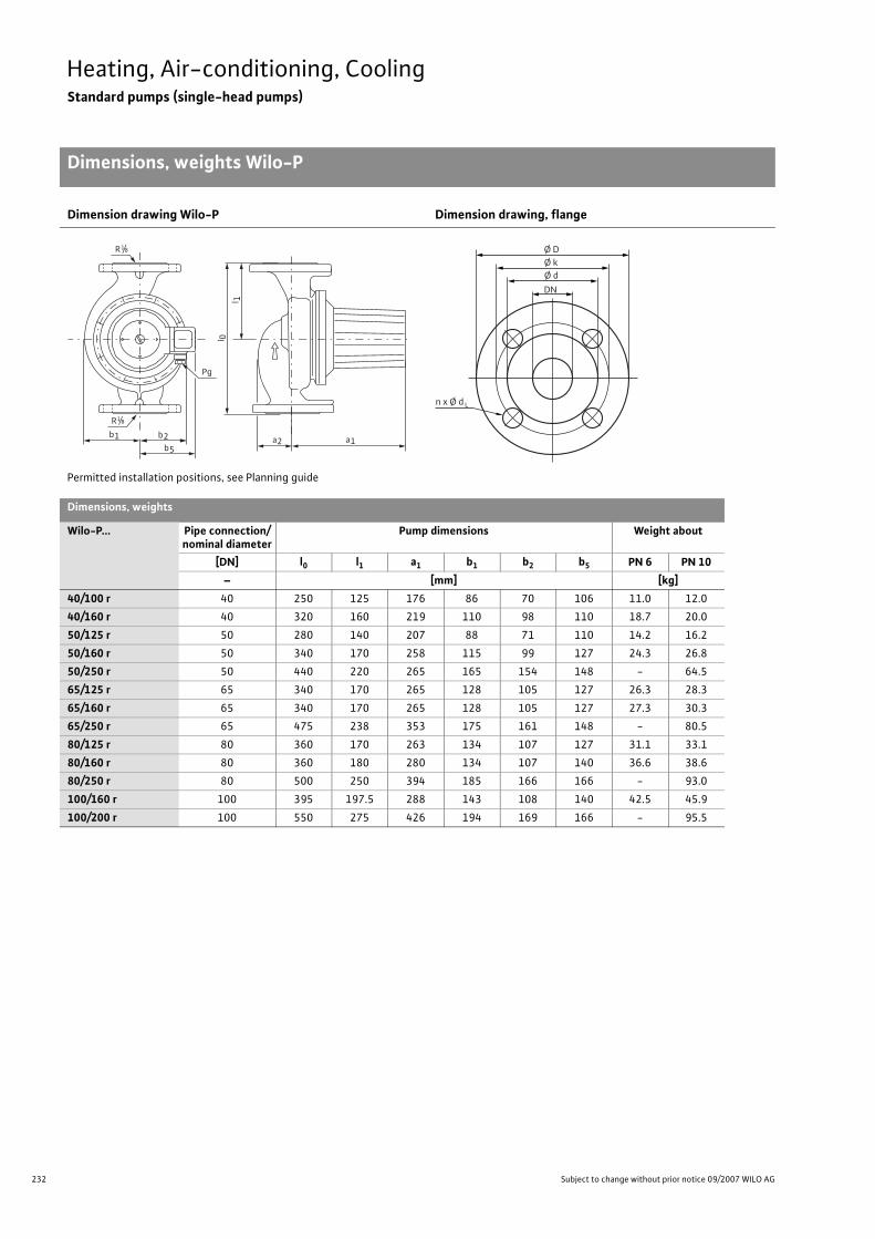
232 Subject to change without prior notice 09/2007 WILO AG
Heating, Air-conditioning, CoolingStandard pumps (single-head pumps)
Dimensions, weights Wilo-P
Dimension drawing Wilo-P Dimension drawing, flange
Permitted installation positions, see Planning guide
Dimensions, weights
Wilo-P... Pipe connection/nominal diameter
Pump dimensions Weight about
[DN] l0 l1 a1 b1 b2 b5 PN 6 PN 10– [mm] [kg]
40/100 r 40 250 125 176 86 70 106 11.0 12.0
40/160 r 40 320 160 219 110 98 110 18.7 20.0
50/125 r 50 280 140 207 88 71 110 14.2 16.2
50/160 r 50 340 170 258 115 99 127 24.3 26.8
50/250 r 50 440 220 265 165 154 148 - 64.5
65/125 r 65 340 170 265 128 105 127 26.3 28.3
65/160 r 65 340 170 265 128 105 127 27.3 30.3
65/250 r 65 475 238 353 175 161 148 - 80.5
80/125 r 80 360 170 263 134 107 127 31.1 33.1
80/160 r 80 360 180 280 134 107 140 36.6 38.6
80/250 r 80 500 250 394 185 166 166 - 93.0
100/160 r 100 395 197.5 288 143 108 140 42.5 45.9
100/200 r 100 550 275 426 194 169 166 - 95.5
R 1/8
Pg
R 1/8
b5
b1 b2
l 0
a1a2
l 1
n x Ø d
Ø D Ø k
DN
Ø d
L
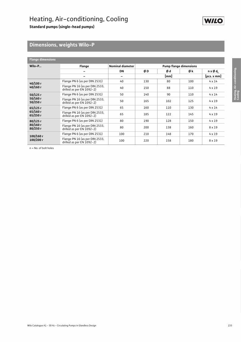
233
Heating, Air-conditioning, CoolingStandard pumps (single-head pumps)
Dimensions, weights Wilo-P
Wilo Catalogue A1 - 50 Hz - Circulating Pumps in Glandless Design
Hea
ting,
Air-
cond
ition
ing,
Co
olin
gSe
cond
ary
Hot W
ater
Circ
ulat
ion
Sola
r The
rmal
, Geo
ther
mal
En
ergy
Sys
tem
sSe
rvic
e/Ac
cess
orie
s, S
yste
ms
Switc
hgea
rs a
nd C
ontr
ol
Dev
ices
Pum
p M
anag
emen
t Sys
tem
s
Flange dimensions
Wilo-P... Flange Nominal diameter Pump flange dimensions– DN Ø D Ø d Ø k n x Ø dL – – [mm] [pcs. x mm]
40/100 r40/160 r
Flange PN 6 (as per DIN 2531) 40 130 80 100 4 x 14Flange PN 16 (as per DIN 2533,drilled as per EN 1092-2) 40 150 88 110 4 x 19
50/125 r50/160 r50/250 r
Flange PN 6 (as per DIN 2531) 50 140 90 110 4 x 14Flange PN 16 (as per DIN 2533,drilled as per EN 1092-2) 50 165 102 125 4 x 19
65/125 r65/160 r65/250 r
Flange PN 6 (as per DIN 2531) 65 160 110 130 4 x 14Flange PN 16 (as per DIN 2533,drilled as per EN 1092-2) 65 185 122 145 4 x 19
80/125 r80/160 r80/250 r
Flange PN 6 (as per DIN 2531) 80 190 128 150 4 x 19Flange PN 16 (as per DIN 2533,drilled as per EN 1092-2) 80 200 138 160 8 x 19
100/160 r100/200 r
Flange PN 6 (as per DIN 2531) 100 210 148 170 4 x 19Flange PN 16 (as per DIN 2533,drilled as per EN 1092-2) 100 220 158 180 8 x 19
n = No. of bolt holes

234 Subject to change without prior notice 09/2007 WILO AG
Heating, Air-conditioning, CoolingStandard pumps (twin-head pumps)
Equipment/function Wilo-Star-RSD, TOP-SD, SE-TW, DOP
Wilo-Star-RSD(ClassicStar)
Wilo-TOP-SD Wilo-SE-TW Wilo-DOP
(max. 2850 1/min) (max. 2850 1/min) (max. 2880 1/min) (max. 1400 1/min)
Operating modes
Speed-stage switching • • • •Manual control mode (n=constant) – – – –
�p-c for constant differential pressure – – – –
�p-v for variable differential pressure – – – –
�p-T for temperature-prompted differential pres-sure – – – –
Manual functions
Setting the operating mode – – – –
Setting the differential-pressure setpoint – – – –
Setting to “Autopilot” (automatic setback operation) – – – –
Setting the pump to ON/OFF – – – –
Setting the speed (manual setting mode) – – – –
Setting the speed stages3 3
(2 for 1~pumps with P2 � 350 W)
3 4
Automatic functions
Stageless power adjustment depending on the oper-ating mode – – – –
“Autopilot” automatic setback operation – – – –
Deblocking function – – – –
Soft start – – – –
Safety control – – – –
Full motor protection with integrated trip electronics
– •(standard equipment only with 3~pumps
with P2 � 180 W and 1~pumps with
P2 � 350 W, optional for all types with Wilo-
Protect-Module C)
•(optional for all types with Wilo-Protect-
Module C)
–
External control functions
Control input “Overriding Off” –
•(optional for all types with Wilo-Protect-
Module C)
•(optional for all types with Wilo-Protect-
Module C)
–
Control input “Overriding Min” – – – –
Control input “Analogue In 0 - 10 V” (remote speed adjustment) – – – –
Control input “Analogue In 0 - 10 V” (remote setpoint adjustment) – – – –
• = available, – = not available
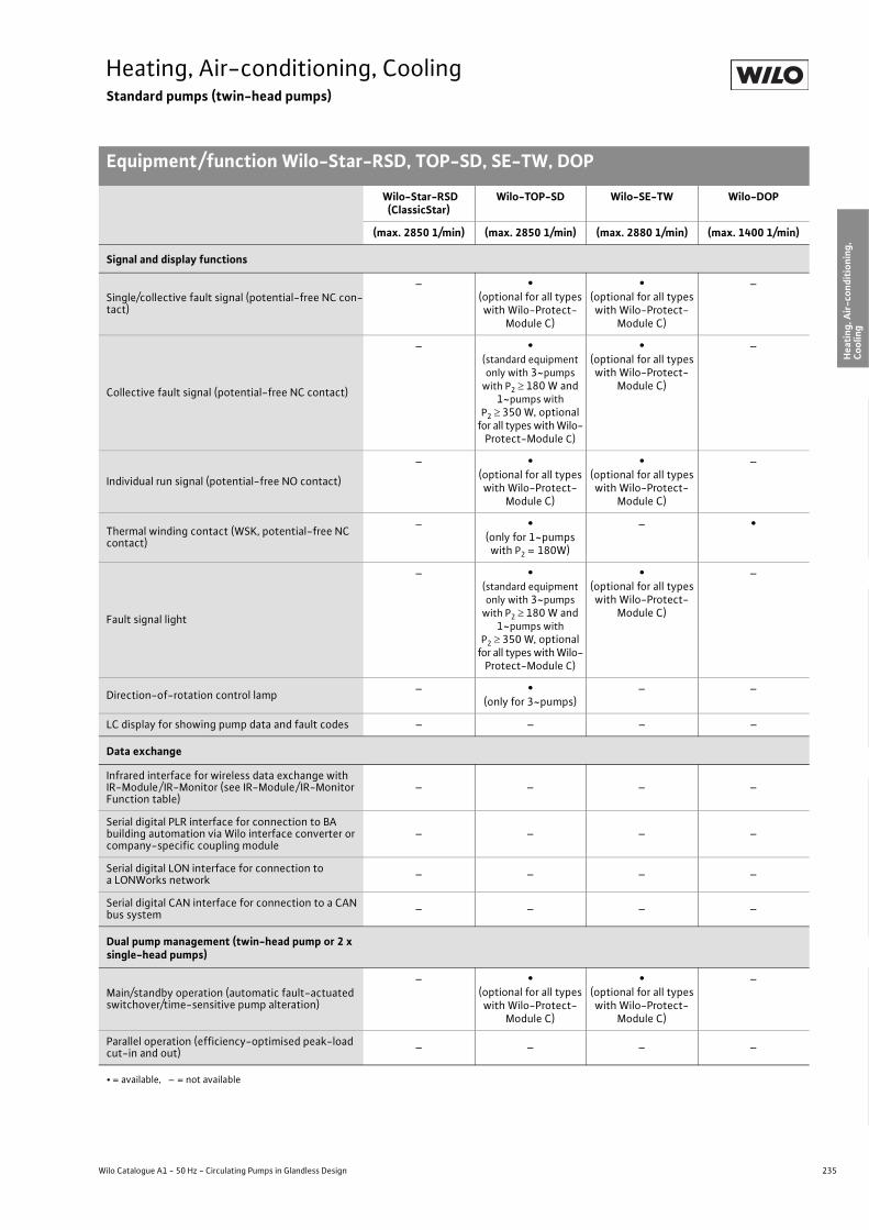
235
Heating, Air-conditioning, CoolingStandard pumps (twin-head pumps)
Equipment/function Wilo-Star-RSD, TOP-SD, SE-TW, DOP
Wilo Catalogue A1 - 50 Hz - Circulating Pumps in Glandless Design
Hea
ting,
Air-
cond
ition
ing,
Co
olin
gSe
cond
ary
Hot W
ater
Circ
ulat
ion
Sola
r The
rmal
, Geo
ther
mal
En
ergy
Sys
tem
sSe
rvic
e/Ac
cess
orie
s, S
yste
ms
Switc
hgea
rs a
nd C
ontr
ol
Dev
ices
Pum
p M
anag
emen
t Sys
tem
s
Signal and display functions
Single/collective fault signal (potential-free NC con-tact)
– •(optional for all types with Wilo-Protect-
Module C)
•(optional for all types with Wilo-Protect-
Module C)
–
Collective fault signal (potential-free NC contact)
– •(standard equipment only with 3~pumps
with P2 � 180 W and 1~pumps with
P2 � 350 W, optional for all types with Wilo-
Protect-Module C)
•(optional for all types with Wilo-Protect-
Module C)
–
Individual run signal (potential-free NO contact)
– •(optional for all types with Wilo-Protect-
Module C)
•(optional for all types with Wilo-Protect-
Module C)
–
Thermal winding contact (WSK, potential-free NC contact)
– •(only for 1~pumps
with P2 = 180W)
– •
Fault signal light
– •(standard equipment only with 3~pumps
with P2 � 180 W and 1~pumps with
P2 � 350 W, optional for all types with Wilo-
Protect-Module C)
•(optional for all types with Wilo-Protect-
Module C)
–
Direction-of-rotation control lamp – •(only for 3~pumps)
– –
LC display for showing pump data and fault codes – – – –
Data exchange
Infrared interface for wireless data exchange with IR-Module/ IR-Monitor (see IR-Module/ IR-Monitor Function table)
– – – –
Serial digital PLR interface for connection to BA building automation via Wilo interface converter or company-specific coupling module
– – – –
Serial digital LON interface for connection to a LONWorks network – – – –
Serial digital CAN interface for connection to a CAN bus system – – – –
Dual pump management (twin-head pump or 2 x single-head pumps)
Main/standby operation (automatic fault-actuated switchover/time-sensitive pump alteration)
– •(optional for all types with Wilo-Protect-
Module C)
•(optional for all types with Wilo-Protect-
Module C)
–
Parallel operation (efficiency-optimised peak-load cut-in and out) – – – –
Wilo-Star-RSD(ClassicStar)
Wilo-TOP-SD Wilo-SE-TW Wilo-DOP
(max. 2850 1/min) (max. 2850 1/min) (max. 2880 1/min) (max. 1400 1/min)
• = available, – = not available

236 Subject to change without prior notice 09/2007 WILO AG
Heating, Air-conditioning, CoolingStandard pumps (twin-head pumps)
Equipment/function Wilo-Star-RSD, TOP-SD, SE-TW, DOP
Equipment/scope of delivery
Wrench attachment point on pump body – – – –
Double switchover valve in pump housing • • • •
Cable entry possible on both sides
• •(only for 1~ and
3~ pumps with P2 � 180W)
– –
Quick connection with spring clips • – – –
Integrated air extraction fitting for automatic rapid ventilator Rp 3/8
– – – –
Plug-in slot for optional expansion with Wilo-IF-Modules – – – –
Blocking current-proof motor • – – –
Including seals for threaded connection (loose)• •
(only forTOP-SD 30/5)
•(only for
SE 125-N-TW)
–
Including installation and operating instructions • • • •Including thermal insulation – – – –
Including washers for flange bolts(for nominal connection widths DN 32 - DN 65) – • • –
Incl. 1.8 m power cable with grounding plug – – – –
Integrated non-return valve – – – –
Integrated ball shutoff valve – – – –
Including clock timer – – – –
Wilo-Star-RSD(ClassicStar)
Wilo-TOP-SD Wilo-SE-TW Wilo-DOP
(max. 2850 1/min) (max. 2850 1/min) (max. 2880 1/min) (max. 1400 1/min)
• = available, – = not available
237
Heating, Air-conditioning, CoolingStandard pumps (twin-head pumps)
Equipment/function Wilo-Star-RSD, TOP-SD, SE-TW, DOP
Wilo Catalogue A1 - 50 Hz - Circulating Pumps in Glandless Design
Hea
ting,
Air-
cond
ition
ing,
Co
olin
gSe
cond
ary
Hot W
ater
Circ
ulat
ion
Sola
r The
rmal
, Geo
ther
mal
En
ergy
Sys
tem
sSe
rvic
e/Ac
cess
orie
s, S
yste
ms
Switc
hgea
rs a
nd C
ontr
ol
Dev
ices
Pum
p M
anag
emen
t Sys
tem
s

238 Subject to change without prior notice 09/2007 WILO AG
Heating, Air-conditioning, CoolingStandard pumps (twin-head pumps)
Series description Wilo-Star-RSD (ClassicStar)
Wilo-Star-RSD (ClassicStar)
ConstructionGlandless circulating pump with screwed connection; preselectable speed stages for power adjustment
ApplicationHot-water heating systems for all systems, industrial circulating sys-tems, cold water systems and air-conditioning systems
Type keyExample: Wilo-Star-RSD 30/4Star-RSD Standard pump (screw-end pump)D Twin-head pump30/ Nominal connection width4 Nominal delivery head [m] for Q = 0 m3/h
Special features/product advantages• Twin-head pump for single or parallel operation• Suitable for any installation position with horizontal shaft; terminal
box in 3-6-9-12 o'clock position• Preselectable 3 speed stages for load adjustment• Increased reliability in individual operation due to the constant avail-
ability of a standby unit ready for operation
Q[m³/h]2 31 4 5 6 7
H[m]
0
0,5
1,0
1,5
2,0
2,5
3,0
3,5
4,0
4,5
5,0
5,5
Star-RSD 30/6
Star-RSD 30/4
Wilo-ClassicStar+

239
Heating, Air-conditioning, CoolingStandard pumps (twin-head pumps)
Series description Wilo-Star-RSD (ClassicStar)
Wilo Catalogue A1 - 50 Hz - Circulating Pumps in Glandless Design
Hea
ting,
Air-
cond
ition
ing,
Co
olin
gSe
cond
ary
Hot W
ater
Circ
ulat
ion
Sola
r The
rmal
, Geo
ther
mal
En
ergy
Sys
tem
sSe
rvic
e/Ac
cess
orie
s, S
yste
ms
Switc
hgea
rs a
nd C
ontr
ol
Dev
ices
Pum
p M
anag
emen
t Sys
tem
s
Equipment/function
Operating modes• Speed-stage switching
Manual functions• Selection of speed stages (3 speed stages)
Equipment/scope of delivery• Double switchover valve in pump housing• Cable entry possible on both sides• Quick connection with spring clips• Blocking current-proof motor• Including seals for threaded connection (loose)• Including installation and operating instructions
Accessories• Screwed connections• Switchgear S2R3D for time-dependent pump alteration and/or assist
switching
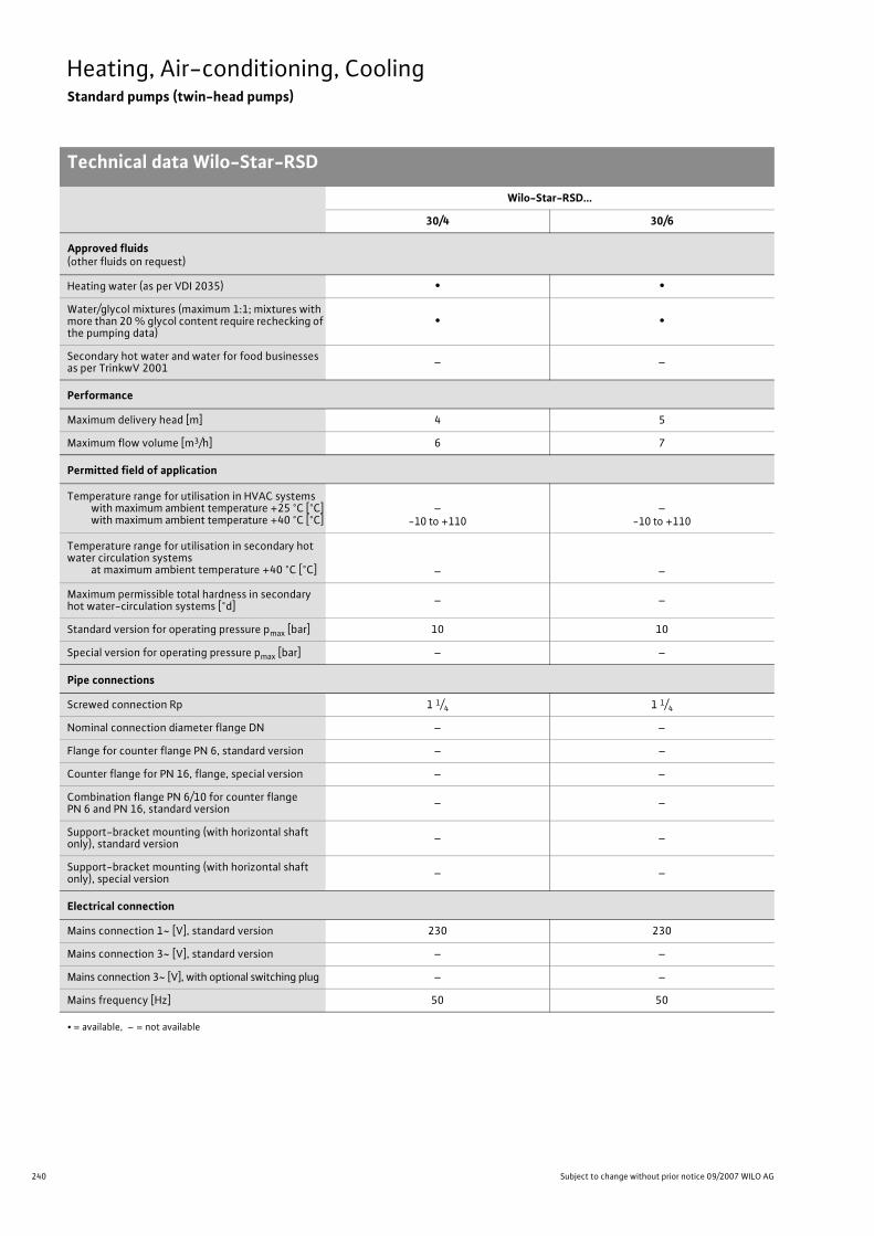
240 Subject to change without prior notice 09/2007 WILO AG
Heating, Air-conditioning, CoolingStandard pumps (twin-head pumps)
Technical data Wilo-Star-RSD
Wilo-Star-RSD...
30/4 30/6
Approved fluids(other fluids on request)
Heating water (as per VDI 2035) • •Water/glycol mixtures (maximum 1:1; mixtures with more than 20 % glycol content require rechecking of the pumping data)
• •
Secondary hot water and water for food businesses as per TrinkwV 2001 – –
Performance
Maximum delivery head [m] 4 5
Maximum flow volume [m3/h] 6 7
Permitted field of application
Temperature range for utilisation in HVAC systemswith maximum ambient temperature +25 °C [°C]with maximum ambient temperature +40 °C [°C]
–-10 to +110
–-10 to +110
Temperature range for utilisation in secondary hot water circulation systems
at maximum ambient temperature +40 °C [°C] – –
Maximum permissible total hardness in secondary hot water-circulation systems [°d] – –
Standard version for operating pressure pmax [bar] 10 10
Special version for operating pressure pmax [bar] – –
Pipe connections
Screwed connection Rp 1 1/4 1 1/4
Nominal connection diameter flange DN – –
Flange for counter flange PN 6, standard version – –
Counter flange for PN 16, flange, special version – –
Combination flange PN 6/10 for counter flange PN 6 and PN 16, standard version – –
Support-bracket mounting (with horizontal shaft only), standard version – –
Support-bracket mounting (with horizontal shaft only), special version – –
Electrical connection
Mains connection 1~ [V], standard version 230 230
Mains connection 3~ [V], standard version – –
Mains connection 3~ [V], with optional switching plug – –
Mains frequency [Hz] 50 50
• = available, – = not available

241
Heating, Air-conditioning, CoolingStandard pumps (twin-head pumps)
Technical data Wilo-Star-RSD
Wilo Catalogue A1 - 50 Hz - Circulating Pumps in Glandless Design
Hea
ting,
Air-
cond
ition
ing,
Co
olin
gSe
cond
ary
Hot W
ater
Circ
ulat
ion
Sola
r The
rmal
, Geo
ther
mal
En
ergy
Sys
tem
sSe
rvic
e/Ac
cess
orie
s, S
yste
ms
Switc
hgea
rs a
nd C
ontr
ol
Dev
ices
Pum
p M
anag
emen
t Sys
tem
s
Motor/electronics
Electromagnetic compatibility – –
Emitted interference EN 61000-6-3 EN 61000-6-3
Immunity to interference EN 61000-6-2 EN 61000-6-2
Power electronics – –
Protection class IP 44 IP 44
Insulation class F F
Materials
Pump housing Cast iron (EN-GJL 200)
Cast iron (EN-GJL 200)
Impeller Plastic (PP) Plastic (PP)
Shaft Stainless steel X40 (Cr13)
Stainless steel X40 (Cr13)
Bearing Metal-impregnated carbon Metal-impregnated carbon
Minimum suction head at suction port [m]for the prevention of cavitation at water delivery temperature
50 °C 0.5 0.5
95 °C 3 3
110 °C 10 10
Wilo-Star-RSD...
30/4 30/6
• = available, – = not available

242 Subject to change without prior notice 09/2007 WILO AG
Heating, Air-conditioning, CoolingStandard pumps (twin-head pumps)
Pump curves Wilo-Star-RSD
Wilo-Star-RSD 30/4
Individual operation Parallel operation
Wilo-Star-RSD 30/6
Individual operation Parallel operation
�
Q �
�
0
00
0
0
0,5
[l/s]
020
Wilo-Star-RSD 30/41 ~ 230 V – Rp11/4
0,5
1,0
[m/s]
1
2
3
4
v �
0
0,5
0,75
80
60
40
1,0
1,0 1,5 2,0 2,5
max.
0,25
0,5 1,5 2,0 2,5
2,5 5 7,5 10
3,0
min
3,0
max.
min.
P1 [W
] H
[m]
[m3/h]
[lgpm]
[m3/h]
P1 [W
] �
Q �
H [m
] �
0
00
0
0
1 [m3/h]
[l/s]
[lgpm]
040
1,0
2
[m/s]
1
2
3
4
v �
0
0,5
1,5
140
100
80
1,0
2 3 4 5
0,5
1 3 4 5
5 10 15 20
6
min
6
1,5 2,0
max.
160
120
60
Wilo-Star-RSD 30/41 ~ 230 V – Rp11/4
max.
min.
[m3/h]
+
�
Q �
�
0
00
0
0
0,5
[l/s]
040
Wilo-Star-RSD 30/61 ~ 230 V – Rp11/ 4
0,5
1,0
[m/s]
1
v �
0
0,5
0,75
100
80
60
1,0
1,0 1,5 2,0 2,5
0,25
0,5 1,5 2,0 2,5
min.
2,5 5 7,5 10
3,0
3,0
0,25 0,75 1,25
2
3
4
5
6
3,5
max.
min.
1
120
3,5
max.
P1 [W
] H
[m]
[m3/h]
[lgpm]
[m3/h]
�
� �
�
0
00
0
0
1
[l/s]
080
1,0
2
[m/s]
1
v c
0
1,0
1,5
200
160
120
2,0
2 3 4 5
0,5
1 3 4 5
5 10 15 20
6
6
0,5 1,5 2,5
2
3
4
5
6
7
max.
2,0
240
7
min.
min.
max.
Wilo-Star-RSD 30/61 ~ 230 V – Rp1 1/ 4
P1 [W
] H
[m]
[m3/h]
[lgpm]
[m3/h]
+

243
Heating, Air-conditioning, CoolingStandard pumps (twin-head pumps)
Terminal diagrams, motor data, dimensions, weights Wilo-Star-RSD
Wilo Catalogue A1 - 50 Hz - Circulating Pumps in Glandless Design
Hea
ting,
Air-
cond
ition
ing,
Co
olin
gSe
cond
ary
Hot W
ater
Circ
ulat
ion
Sola
r The
rmal
, Geo
ther
mal
En
ergy
Sys
tem
sSe
rvic
e/Ac
cess
orie
s, S
yste
ms
Switc
hgea
rs a
nd C
ontr
ol
Dev
ices
Pum
p M
anag
emen
t Sys
tem
s
Always refer to name plate data!
Terminal diagram Dimension drawing
1-phase motor (EM) 2-pole - 1~230 V, 50 Hzwith integrated capacitor
Motor data
Wilo-Star-RSD... Nominalpower
Speed Power consumption
Current at Motor protection Capacitor Threaded cable
connection1~230 V 3~230 V 3~400 VP2 n P1 I – Capacity PG
[W] [1/min] [W] [A] – �F/VDB] –
30/422137
max.
min.
2000 16501200
60 - 6743 - 4829 - 31
0.290.210.14
– –not necessary (blocking cur-
rent-proof)2.0/400 11
30/6352112
max.
min.
2200 19001200
80 - 9960 - 7443 - 50
0.410.320.22
– –not necessary (blocking cur-
rent-proof)2.6/400 11
Dimensions. weights
Wilo-Star-RSD... Pipe connection/nominal diameter
Thread Pump dimensions Weight approxi-mately
[Rp/DN] G I0 l1 l2 m a a1 b b1 b2 b3 b4 –– – [mm] [kg]
30/4 Rp 1 1/4 2 180 94 73 70 47 78 46 55 55 54 92.5 5.3
30/6 Rp 1 1/4 2 180 94 76 70 47 78 46 55 55 54 92.5 5.5
L N PE
a
PG 11
l0 l1
b3
b2
b1
b4
G
b
l2 a1mPG 11

244 Subject to change without prior notice 09/2007 WILO AG
Heating, Air-conditioning, CoolingStandard pumps (twin-head pumps)
Series description Wilo-TOP-SD
Wilo-TOP-SD
ConstructionGlandless pump twin-head circulating pump with flange connection (TOP-SD 30/5 with screwed connection).
ApplicationHot-water heating systems for all systems, industrial circulating sys-tems, air-conditioning systems and closed cooling circuits
Type keyExample: Wilo-TOP-SD 40/7TOP-SD Standard twin-head pump (flange-end pump,
TOP-SD 30/5 with screwed connection)40/ Nominal connection width7 Nominal delivery head [m] for Q = 0 m3/h
Options• Special versions for operating pressure PN 16 (at additional charge)• Versions for special voltages on request
Special features/product advantages• Can be used in heating systems and in cooling/air-conditioning sys-
tems from -20 °C to +130 °C• Twin-head pump for main/standby operation or parallel operation• Manual power adjustment with 2 speed stages
(for pumps 1~230 V with P2 � 350 W) or with 3 speed stages• Pump housing with cataphoretic (KTL) coating for the prevention of
corrosion from condensation formation• Easy installation using combination flange PN 6/PN 10
(for DN 32 to DN 65)• Cable feed to terminal box possible on both sides (starting with
P1 � 250 W) with integrated strain-relief device• Protection class IP 44
ATTENTION:For EEI classification for each pump model see Chapter “Planning guide”, Table on page 20.
Q[m³/h]1 2 3 4 5 6 8 10 20 30 40 50 60 80
H[m]
0
2
4
6
8
10
12
14
16
80/10
30/5
32/7
40/3
40/7
40/10
50/750/10 65/10
65/13
65/15
50/15
40/15
Wilo-TOP-SD+

245
Heating, Air-conditioning, CoolingStandard pumps (twin-head pumps)
Series description Wilo-TOP-SD
Wilo Catalogue A1 - 50 Hz - Circulating Pumps in Glandless Design
Hea
ting,
Air-
cond
ition
ing,
Co
olin
gSe
cond
ary
Hot W
ater
Circ
ulat
ion
Sola
r The
rmal
, Geo
ther
mal
En
ergy
Sys
tem
sSe
rvic
e/Ac
cess
orie
s, S
yste
ms
Switc
hgea
rs a
nd C
ontr
ol
Dev
ices
Pum
p M
anag
emen
t Sys
tem
s
Equipment/function
Operating modes• Speed-stage switching
Manual functions• Setting the speed stages: 3 speed stages
(2 speed stages for 1~pumps with P2 � 350 W)
Automatic functions• Full motor protection with integrated trip electronics
(standard equipment only for 3~pumps with P2 � 180 W and 1~pumps with P2 � 350 W, optional for all types with Wilo-Protect-Module C)
External control functions• Control input “Overriding Off”
(optional for all types with Wilo-Protect-Module C)
Signal and display functions• Individual/collective fault signal (potential-free NC contact)
(optional for all types with Wilo-Protect-Module C)• Collective fault signal (potential-free NC contact)
(standard equipment only with 3~pumps with P2 � 180 W and 1~pumps with P2 � 350 W, optional for all types with Wilo-Protect-Module C)
• Individual run signal (potential-free NO contact)(optional for all types with Wilo-Protect-Module C)
• Thermal winding contact (WSK, potential-free NC contact)(only for 1~pumps with P2 180 W)
• Fault signal light (standard equipment only for 3~pumps with P2 � 180 W and 1~pumps with P2 � 350 W, optional for all types with Wilo-Protect-Module C)
• Direction of rotation control lamp (standard equipment only with 3~pumps)
Dual pump management (twin-head pump or 2 x single-head pumps)
• Main/standby operation (automatic fault-actuated switchover/me-sensitive pump alteration): (optional for all types with Wilo-Protect-Module C)
Equipment/scope of delivery• Double switchover valve in pump housing• Cable feed possible from both sides (only with 1~pumps and
3~pumps with P2 � 180 W)• Including seals with screw thread (loose) (only with TOP-SD 30/5)• Including installation and operating instructions• Including washers for flange bolts
(for nominal connection widths DN 32 - DN 65)
Accessories• Screwed connections for screw thread (for TOP-SD 30/5)• Mounting brackets for pump fixation• For pumps 3~400 V:
- Switching plug 3~230 V, 50 Hz (2 plugs required)- Wilo-Protect-Module C 3~400 V (2 modules required)
• For pumps 1~230 V:- Wilo relay SK 602/SK 622- Wilo-Protect-Module C 1~230 V (2 modules required)

246 Subject to change without prior notice 09/2007 WILO AG
Heating, Air-conditioning, CoolingStandard pumps (twin-head pumps)
Technical data Wilo-TOP-SD
Wilo-TOP-SD...
30/5 32/7 32/10 40/3 40/7 40/10 40/15
Approved fluids(other fluids on request)
Heating water (as per VDI 2035) • • • • • • •Water/glycol mixtures (maximum 1:1; mixtures with more than 20 % glycol content require rechecking of the pumping data)
• • • • • • •
Secondary hot water and water for food businesses as per TrinkwV 2001 – – – – – – –
Performance
Maximum delivery head [m] 5.5 7 12 3.5 7 10 15
Maximum flow volume [m3/h] 10 13 18 16 28 34 33
Permitted field of application
Temperature range for utilisation in HVAC systemswith maximum ambient temperature +25 °C [°C]with maximum ambient temperature +40 °C [°C]
–-20 to +130 (in short-term operation 2 h: +140)
(for utilisation with Wilo-Protect-Module C: -20 to +110)
Temperature range for utilisation in secondary hot water circulation systems
at maximum ambient temperature +40 °C [°C] – – – – – – –
Maximum permissible total hardness in secondary hot water-circulation systems [°d] – – – – – – –
Standard version for operating pressure pmax [bar] 10 6/10 6/10 6/10 6/10 6/10 6/10
Special version for operating pressure pmax [bar] – – – – 16 16 16
Pipe connections
Screwed connection Rp 1 1/4 – – – – – –
Nominal connection diameter flange DN – 32 32 40 40 40 50
Flange for counter flange PN 6, standard version – – – – – – –
Counter flange for PN 16, flange, special version – – – – • • •
Combination flange PN 6/10 for counter flange PN 6 and PN 16, standard version – • • • • • •
Support-bracket mounting (with horizontal shaft only), standard version – – – – – – •
Support-bracket mounting (with horizontal shaft only), special version – – – • • • –
Electrical connection
Mains connection 1~ [V], standard version 230 230 230 230 230 230 230
Mains connection 3~ [V], standard version 400 400 400 400 400 400 400
Mains connection 3~ [V], with optional switching plug 230 230 230 230 230 230 230
Mains frequency [Hz] 50 50 50 50 50 50 50
• = available, – = not available
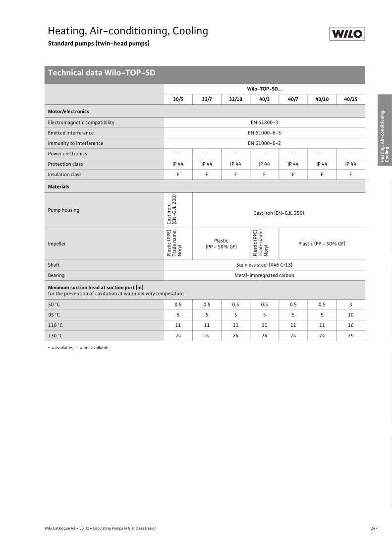
247
Heating, Air-conditioning, CoolingStandard pumps (twin-head pumps)
Technical data Wilo-TOP-SD
Wilo Catalogue A1 - 50 Hz - Circulating Pumps in Glandless Design
Hea
ting,
Air-
cond
ition
ing,
Co
olin
gSe
cond
ary
Hot W
ater
Circ
ulat
ion
Sola
r The
rmal
, Geo
ther
mal
En
ergy
Sys
tem
sSe
rvic
e/Ac
cess
orie
s, S
yste
ms
Switc
hgea
rs a
nd C
ontr
ol
Dev
ices
Pum
p M
anag
emen
t Sys
tem
s
Motor/electronics
Electromagnetic compatibility EN 61800-3
Emitted interference EN 61000-6-3
Immunity to interference EN 61000-6-2
Power electronics – – – – – – –
Protection class IP 44 IP 44 IP 44 IP 44 IP 44 IP 44 IP 44
Insulation class F F F F F F F
Materials
Pump housing
Cast
iron
(EN
-GJL
200
)
Cast iron (EN-GJL 250)
Impeller
Plas
tic (P
PE)
Trad
e na
me:
Nor
yl
Plastic(PP - 50% GF)
Plas
tic (P
PE)
Trad
e na
me:
Nor
yl Plastic (PP - 50% GF)
Shaft Stainless steel (X46 Cr13)
Bearing Metal-impregnated carbon
Minimum suction head at suction port [m]for the prevention of cavitation at water delivery temperature
50 °C 0.5 0.5 0.5 0.5 0.5 0.5 3
95 °C 5 5 5 5 5 5 10
110 °C 11 11 11 11 11 11 16
130 °C 24 24 24 24 24 24 29
Wilo-TOP-SD...
30/5 32/7 32/10 40/3 40/7 40/10 40/15
• = available, – = not available
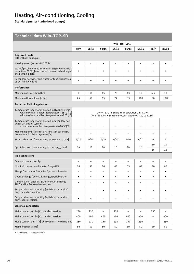
248 Subject to change without prior notice 09/2007 WILO AG
Heating, Air-conditioning, CoolingStandard pumps (twin-head pumps)
Technical data Wilo-TOP-SD
Wilo-TOP-SD...
50/7 50/10 50/15 65/10 65/13 65/15 80/7 80/10
Approved fluids(other fluids on request)
Heating water (as per VDI 2035) • • • • • • • •Water/glycol mixtures (maximum 1:1; mixtures with more than 20 % glycol content require rechecking of the pumping data)
• • • • • • • •
Secondary hot water and water for food businesses as per TrinkwV 2001 – – – – – – – –
Performance
Maximum delivery head [m] 7 10 15 9 13 15 6.5 10
Maximum flow volume [m3/h] 45 50 65 74 83 100 80 118
Permitted field of application
Temperature range for utilisation in HVAC systemswith maximum ambient temperature +25 °C [°C]with maximum ambient temperature +40 °C [°C]
–-20 to +130 (in short-term operation 2 h: +140)
(for utilisation with Wilo-Protect-Module C: -20 to +110)
Temperature range for utilisation in secondary hot water circulation systems
at maximum ambient temperature +40 °C [°C]–
– – – – – – –
Maximum permissible total hardness in secondary hot water-circulation systems [°d] – – – – – – – –
Standard version for operating pressure pmax [bar] 6/10 6/10 6/10 6/10 6/10 6/10 6 6
Special version for operating pressure pmax [bar] 16 16 16 16 16 1610 10
16 16
Pipe connections
Screwed connection Rp – – – – – – – –
Nominal connection diameter flange DN 50 50 50 65 65 65 80 80
Flange for counter flange PN 6, standard version – – – – – – • •Counter flange for PN 16, flange, special version • • • • • • • •Combination flange PN 6/10 for counter flange PN 6 and PN 16, standard version • • • • • • – –
Support-bracket mounting (with horizontal shaft only), standard version – – • • • • • •
Support-bracket mounting (with horizontal shaft only), special version • • – – – – – –
Electrical connection
Mains connection 1~ [V], standard version 230 230 – 230 – – 230 –
Mains connection 3~ [V], standard version 400 400 400 400 400 400 – 400
Mains connection 3~ [V], with optional switching plug 230 230 230 230 230 230 – 230
Mains frequency [Hz] 50 50 50 50 50 50 50 50
• = available, – = not available

249
Heating, Air-conditioning, CoolingStandard pumps (twin-head pumps)
Technical data Wilo-TOP-SD
Wilo Catalogue A1 - 50 Hz - Circulating Pumps in Glandless Design
Hea
ting,
Air-
cond
ition
ing,
Co
olin
gSe
cond
ary
Hot W
ater
Circ
ulat
ion
Sola
r The
rmal
, Geo
ther
mal
En
ergy
Sys
tem
sSe
rvic
e/Ac
cess
orie
s, S
yste
ms
Switc
hgea
rs a
nd C
ontr
ol
Dev
ices
Pum
p M
anag
emen
t Sys
tem
s
Motor/electronics
Electromagnetic compatibility EN 61800-3
Emitted interference EN 61000-6-3
Immunity to interference EN 61000-6-2
Power electronics – – – – – – – –
Protection class IP 44 IP 44 IP 44 IP 44 IP 44 IP 44 IP 44 IP 44
Insulation class F F F F F F F F
Materials
Pump housing Cast iron (EN-GJL 250)
Impeller Plastic (PP - 50% GF)
Shaft Stainless steel (X46 Cr13)
Bearing Metal-impregnated carbon
Minimum suction head at suction port [m]for the prevention of cavitation at water delivery temperature
50 °C 3 3 3 3 3 3 3 3
95 °C 10 10 10 10 10 10 10 10
110 °C 16 16 16 16 16 16 16 16
130 °C 29 29 29 29 29 29 29 29
Wilo-TOP-SD...
50/7 50/10 50/15 65/10 65/13 65/15 80/7 80/10
• = available, – = not available

250 Subject to change without prior notice 09/2007 WILO AG
Heating, Air-conditioning, CoolingStandard pumps (twin-head pumps)
Pump curves Wilo-TOP-SD
Wilo-TOP-SD 30/5
AC - individual operation AC - parallel operation
Three-phase - individual operation Three-phase - parallel operation
Q[lgpm]
0
320
240
280
160
200
80
120
40
0 2 0
0
0
0
[l/s]
1
4
5
6
3
2
2
0,5
10 20 30
1,5 2,5 2
4 6 8
3 2 1 0 [m/s] v
1
4 6 8
max.
min.P 1[W]
H[m
]
+
[m3/h]
[m3/h]
max.
min.
Wilo-TOP-SD 30/51~230 V - Rp 1¼
Q[lgpm]
0
160
200
80
120
40
0 2 0
0
0
0
[l/s]
1
4
5
6
3
2
2
0,5
10 20
1,5
4 6
2 1 0 [m/s] v
1
4 6
max.
min.
max.
[m3/h]
[m3/h]
P 1[W]
H[m
]
Wilo-TOP-SD 30/51~230 V - Rp 1¼
min.
Q [lgpm]
0
160
200
80
120
40
0 2 0
0
0
0
[l/s]
1
4
5
6
3
2
2
0,5
10 20
1,5
4 6
2 1 0 [m/s] v
1
4 6
max.
min.
[m3/h]
[m3/h]
P 1[W]
H[m
]
max.
min.
Wilo-TOP-SD 30/53~400 V - Rp 1¼
Q [lgpm]
0
320
240
280
160
200
80
120
40
0 2 0
0
0
0
[l/s]
1
4
5
6
3
2
2
0,5
10 20 30
1,5 2,5 2
4 6 8
3 2 1 0 [m/s] v
1
4 6 8
max.
min.
P 1[W]
H[m
]
+
[m3/h]
[m3/h]
max.
max.
Wilo-TOP-SD 30/53~400 V - Rp 1¼
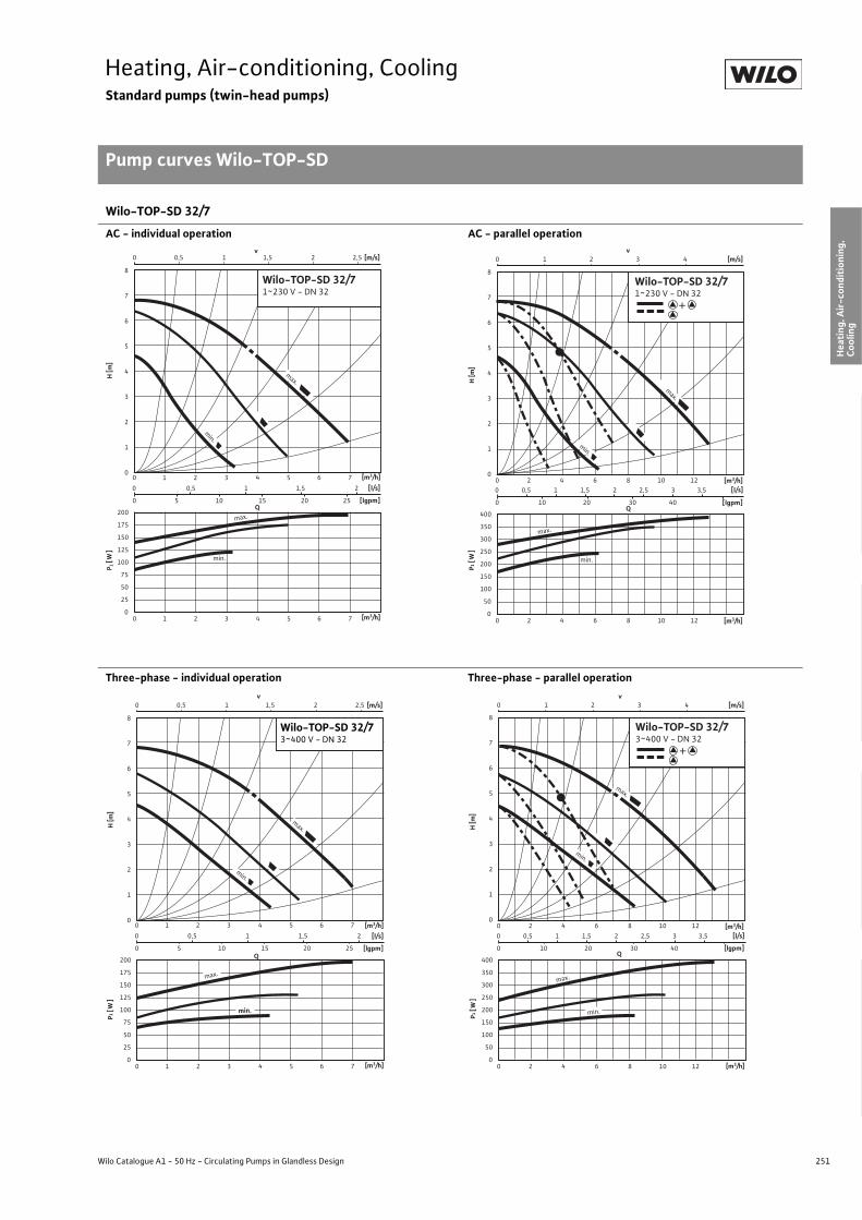
251
Heating, Air-conditioning, CoolingStandard pumps (twin-head pumps)
Pump curves Wilo-TOP-SD
Wilo Catalogue A1 - 50 Hz - Circulating Pumps in Glandless Design
Hea
ting,
Air-
cond
ition
ing,
Co
olin
gSe
cond
ary
Hot W
ater
Circ
ulat
ion
Sola
r The
rmal
, Geo
ther
mal
En
ergy
Sys
tem
sSe
rvic
e/Ac
cess
orie
s, S
yste
ms
Switc
hgea
rs a
nd C
ontr
ol
Dev
ices
Pum
p M
anag
emen
t Sys
tem
s
Wilo-TOP-SD 32/7
AC - individual operation AC - parallel operation
Three-phase - individual operation Three-phase - parallel operation
0 0,5 1 1,5 2
0 5 10 15 20 25
0 0,5 1 1,5 2 2,5
0 1 2 3 4 5 6 7
0 1 2 3 4 5 6 7
v [m/s]
Q[lgpm]
200
175
150
125
100
75
50
25
0
8
7
6
5
4
3
2
1
0
[l/s]
min.
max.
max.
min.
P 1 [
W]
H [m
]
[m3/h]
[m3/h]
Wilo-TOP-SD 32/71~230 V - DN 32
400
350
300
250
200
150
100
50
0
0 0,5 1 1,5 2 2,5 3 3,5
0 10 20 30 40
0 1 2 3 4
0 2 4 6 8 10 12
0 2 4 6 8 10 12
v [m/s]
Q[lgpm]
8
7
6
5
4
3
2
1
0
[l/s]
min.
max.
max.
min.
P1 [
W]
H [m
]
[m3/h]
[m3/h]
+
Wilo-TOP-SD 32/71~230 V - DN 32
0 0,5 1 1,5 2
0 5 10 15 20 25
0 0,5 1 1,5 2 2,5
0 1 2 3 4 5 6 7
0 1 2 3 4 5 6 7
v[m/s]
P1[W
]H
[m]
Q
[m3/h]
[lgpm]
200
175
150
125
100
75
50
25
0
8
7
6
5
4
3
2
1
0
[l/s]
max.
min.
max.
min.
[m3/h]
Wilo-TOP-SD 32/73~400 V - DN 32
400
350
300
250
200
150
100
50
0
0 0,5 1 1,5 2 2,5 3 3,5
0 10 20 30 40
0 1 2 3 4
0 2 4 6 8 10 12
0 2 4 6 8 10 12
v[m/s]
Q[lgpm]
8
7
6
5
4
3
2
1
0
[l/s]
min.
max.
max.
min.
H [m
]P 1
[W]
[m3/h]
[m3/h]
+
Wilo-TOP-SD 32/73~400 V - DN 32

252 Subject to change without prior notice 09/2007 WILO AG
Heating, Air-conditioning, CoolingStandard pumps (twin-head pumps)
Pump curves Wilo-TOP-SD
Wilo-TOP-SD 32/10
AC - individual operation AC - parallel operation
Three-phase - individual operation Three-phase - parallel operation
[m/s]v
0 2 4 6
Q[m³/h]0
Q[l/s]0 1 2 3 4 5 6
Q[Igpm]0 20 40 60
H[m]
0
2
4
6
8
10
12
14
Q[m³/h]0
P1[W]
0
400
800
Wilo-TOP-SD 32/101~230V - DN 32
max.
min.
max.
min.
4 8
4 6
6
10
10
2
2
8
[m/s]v
0 2 4 6
Q[m³/h]0 4 8 12 16 20
Q[l/s]0 1 2 3 4 5 6
Q[Igpm]0 20 40 60
H[m]
0
2
4
6
8
10
12
14
Q[m³/h]0 4 8 12 16 20
P1[W]
0
400
800
Wilo-TOP-SD 32/101~230V - DN 32
max.m
in.
+
max.
min.
H[m]
0
2
4
6
8
10
12
14
P[kW]
0,0
0,4
0,8
Wilo-TOP-SD 32/101~230V - DN 32
[m/s]
Q[m³/h]
Q[l/s]
Q[Igpm]
max.
min.
max.
min.
v
0 2 4 6 8 10
Q[m³/h]0 2 4 6 8 10
0
0 1 2 3
0,5 1 2
0 1 2 3
1,5 1,5
[m/s]0 2 4 6
Q[m³/h]0 4 8 12 16 20
Q[l/s]0 1 2 3 4 5 6
Q[Igpm]0 20 40 60
H[m]
0
2
4
6
8
10
12
14
Q[m³/h]0 4 8 12 16 20
P[kW]
0,0
0,4
0,8
Wilo-TOP-SD 32/101~230V - DN 32
+
max.
min.
max.
min.
v

253
Heating, Air-conditioning, CoolingStandard pumps (twin-head pumps)
Pump curves Wilo-TOP-SD
Wilo Catalogue A1 - 50 Hz - Circulating Pumps in Glandless Design
Hea
ting,
Air-
cond
ition
ing,
Co
olin
gSe
cond
ary
Hot W
ater
Circ
ulat
ion
Sola
r The
rmal
, Geo
ther
mal
En
ergy
Sys
tem
sSe
rvic
e/Ac
cess
orie
s, S
yste
ms
Switc
hgea
rs a
nd C
ontr
ol
Dev
ices
Pum
p M
anag
emen
t Sys
tem
s
Wilo-TOP-SD 40/3
AC - individual operation AC - parallel operation
Three-phase - individual operation Three-phase - parallel operation
Q
0
240
160
200
80
120
40
0
0
0
0
[ l/s]
0,8
3,2
4,0
2,4
1,6
2
1
10 20 30
3
4 6 8 10
2 0,5 0 [m/s] v
1 1,5
2
2 0 4 6 8 10
max.
min.
max.
P1 [
W]
H [m
]
[m 3 /h]
[lgpm ]
[m 3 /h]
Wilo-TOP-SD 40/31~230 V - DN 40
min.
Q
0
320
360
240
280
160
200
80
120
40
0
0
0
0
[ l/s]
0,8
3,2
4,0
2,4
1,6
4
1
25
3 5 4
8 12 16
50
3 2 1 0 [m/s] v
2
4 0 8 12 16
max.
min.
P 1 [
W]
H [m
] [m 3 /h]
[lgpm ]
[m 3 /h]
+
Wilo-TOP-SD 40/31~230 V - DN 40
max.
min.
0,5 0 1 1,5 2
Q [lgpm]
0
240
160
200
80
120
40
0
0
0
0
[l/s]
0,8
3,2
4,0
2,4
1,6
[m 3 /h] 2
1
10 20 30
3
4 6 8 10
[m/s] v
H
[ m
]
2
[m 3 /h]
P 1 [
W]
2 0 4 6 8 10
max.
min.
min.
max.
Wilo-TOP-SD 40/33~400 V - DN 40
Q [lgpm]
0
320
360
1 0 2 3
240
280
160
200
80
120
40
0
0
0
0
[l/s]
0,8
3,2
4,0
2,4
1,6
[m 3 /h] 4
1
25
3 5 4
8 12 16
50
[m/s] v
H
[ m
]
2
[m 3 /h]
4 0 8 12 16
max.
min.
+
Wilo-TOP-SD 40/33~400 V - DN 40
max.
min.

254 Subject to change without prior notice 09/2007 WILO AG
Heating, Air-conditioning, CoolingStandard pumps (twin-head pumps)
Pump curves Wilo-TOP-SD
Wilo-TOP-SD 40/7
AC - individual operation AC - parallel operation
Three-phase - individual operation Three-phase - parallel operation
0 1 2 3 4
0 10 20 30 40 50
0 0,5 1 1,5 2 2,5 3
0 4 8 12 16
0 4 8 12 16
v[m/s]
Q[lgpm]
400
350
300
250
200
150
100
8
7
6
5
4
3
2
1
0
[l/s]
max.
max.
min.
min.
P 1[W
]H
[m]
[m3/h]
[m3/h]
Wilo-TOP-SD 40/71~230 V - DN 40
800
700
600
500
400
300
200
0 1 2 3 4 5 6 7
0 25 50 75
0 1 2 3 4 5
0 5 10 15 20 25
0 5 10 15 20 25
v[m/s]
Q[lgpm]
8
7
6
5
4
3
2
1
0
[l/s]
min.
max.
max.
min.
P1[W
]H
[m]
[m3/h]
[m3/h]
+
Wilo-TOP-SD 40/71~230 V - DN 40
Q[m/s]v
0 1 2 3 4 5 6
Q[m³/h]0 5 10 15
Q[l/s]0 2 4 6 8
Q[Igpm]0 20 40 60 80
H[m]
0
2
4
6
Q[m³/h]0 5 10 15 20 25
P1[W]
0
400
Wilo-TOP-SD 40/73~400V - DN 40
max.
min.
max.
min.
Q[m/s]v
0 1 2 3 4 5 6
Q[m³/h]0 5 10 15 20 25
Q[l/s]0 2 4 6 8
Q[Igpm]0 20 40 60 80
H[m]
0
2
4
6
Q[m³/h]0 5 10 15 20 25
P1[W]
0
400
Wilo-TOP-SD 40/73~400V - DN 40
max.
min.
+
max.
min.

255
Heating, Air-conditioning, CoolingStandard pumps (twin-head pumps)
Pump curves Wilo-TOP-SD
Wilo Catalogue A1 - 50 Hz - Circulating Pumps in Glandless Design
Hea
ting,
Air-
cond
ition
ing,
Co
olin
gSe
cond
ary
Hot W
ater
Circ
ulat
ion
Sola
r The
rmal
, Geo
ther
mal
En
ergy
Sys
tem
sSe
rvic
e/Ac
cess
orie
s, S
yste
ms
Switc
hgea
rs a
nd C
ontr
ol
Dev
ices
Pum
p M
anag
emen
t Sys
tem
s
Wilo-TOP-SD 40/10
AC - individual operation AC - parallel operation
Three-phase - individual operation Three-phase - parallel operation
0
1
2
3
4
5
6
7
8
9
10
11
0
100
200
300
400
500
600
700
0 2 4 6 8 10 12 14 16
0 2 4 6 8 10 12 14 160 1 2 3 4
0 0,5 1,0 1,5 2,0 2,5 3v
Q
max.
min.max.
[m3/h]
[m3/h]
[m/s]
[l/s]
H [m
]P 1
[W]
min.
Wilo-TOP-SD 40/101~230 V - DN 40
0
1
2
3
4
5
6
7
8
9
10
11
0
200
400
600
800
1000
1200
1400
0 5 10 15 20 25 30
0 5 10 15 20 25 300 1 2 3 4 5 6 7 8
0 1 2 3 4 5v
Q
max.
min.
min.max.
[m3/h]
[m3/h]
[m/s]
[l/s]
H [m
]P 1
[W]
+
Wilo-TOP-SD 40/101~230 V - DN 40
0 1 2 3 4 5
0 10 20 30 40 50 60
0 0,5 1 1,5 2 2,5 3 3,5
0 2 4 6 8 10 12 14 16 18
v[m/s]
Q[lgpm]
600
500
400
300
200
100
0
11
10
9
8
7
6
5
4
3
2
1
0
[l/s]
max.
max.
min.
min.
0 2 4 6 8 10 12 14 16 18
P 1[W
]H
[m]
[m3/h]
[m3/h]
Wilo-TOP-SD 40/103~400 V - DN 40
1200
1000
800
600
400
200
0
0 1 2 3 4 5 6 7 8 9
0 20 40 60 80 100
0 1 2 3 4 5 6
0 5 10 15 20 25 30
v[m/s]
Q[lgpm]
11
10
9
8
7
6
5
4
3
2
1
0
[l/s]
min.
max.
0 5 10 15 20 25 30
max.
min.
P1[W
]H
[m]
[m3/h]
[m3/h]
+
Wilo-TOP-SD 40/103~400 V - DN 40

256 Subject to change without prior notice 09/2007 WILO AG
Heating, Air-conditioning, CoolingStandard pumps (twin-head pumps)
Pump curves Wilo-TOP-SD
Wilo-TOP-SD 40/15
AC - individual operation AC - parallel operation
Three-phase - individual operation Three-phase - parallel operation
0 0,5 1 1,5 2,52 3 3,5 4,54 [m/s]v
0
2,5
5
7,5
10
12,5
15
17,5
2,5 7,5 12,5 17,5 Q [m³/h]
H [m
]
0 1 2 3 4 5 Q [l/s]
0 10 20 30 40 50 60 70 Q [Igpm]
0
250
500
750
1000
2,5 7,5 12,5
0 5 10 15
0 5 10 15 17,5 Q [m³/h]
P 1 [W
]
max.
min.
max.
min.
Wilo-TOP-SD-40/151~230 V - DN 40
0 0,5 1 1,5 2 2,5 3 3,5v
4 4,5 5 5,5 6 76,5 [m/s]
0
2,5
5,0
7,5
10,0
12,5
15,0
17,5
20,0
0 5 10 15 20 25 Q [m³/h]
H [m
]
0 1 2 3 4 5 6 7 8 Q [l/s]
0 20 40 60 80 100 Q [Igpm]
0
500
1000
1500
2000
0 5 10 15 20 25 Q [m³/h]
P 1 [W
]
+
Wilo-TOP-SD 40/151~230 V - DN 40
max.
min.
max.
min.
0 0,5 1 1,5 2 2,5 3 3,5 4,54 [m/s]
0
2,5
5,0
7,5
10,0
12,5
15,0
17,5
2,5 7,5 12,5 17,5 Q [m³/h]
H [m
]
0 1 2 3 4 5 Q [l/s]
0 10 20 30 40 50 60 70 Q [Igpm]
0
250
500
750
1000
2,5 7,5 12,5
0 5 10 15
0 5 10 15 17,5 Q [m³/h]
P 1 [W
]
v
max.
min.
max.
min.
Wilo-TOP-SD-40/153~400 V - DN 40
H [m
]P 1
[W]
[m/s]
000 1 2 3
0 10 20 30 40 50 60 70 80 90 100
4 5 6 7 85 10 15 20 25 30 Q [m³/h]
0 5 10 15 20 25 30 Q [m³/h]
Q [l/s]Q [lgpm]
2,5
5
7,5
0
500
1000
1500
2000
10
12,5
15
17,5
20Wilo-TOP-SD 40/153~400 V - DN 40
max.
min.
v0 1 2 3 4 5 6 7
+
max.
min.

257
Heating, Air-conditioning, CoolingStandard pumps (twin-head pumps)
Pump curves Wilo-TOP-SD
Wilo Catalogue A1 - 50 Hz - Circulating Pumps in Glandless Design
Hea
ting,
Air-
cond
ition
ing,
Co
olin
gSe
cond
ary
Hot W
ater
Circ
ulat
ion
Sola
r The
rmal
, Geo
ther
mal
En
ergy
Sys
tem
sSe
rvic
e/Ac
cess
orie
s, S
yste
ms
Switc
hgea
rs a
nd C
ontr
ol
Dev
ices
Pum
p M
anag
emen
t Sys
tem
s
Wilo-TOP-SD 50/7
AC - individual operation AC - parallel operation
Three-phase - individual operation Three-phase - parallel operation
0
1
2
3
4
5
6
7
0
100
200
300
400
500
600
700
0 5 10 15 20
0 5 10 15 200 1 2 3 4 5 6
0 0,5 1,0 1,5 2,0 2,5v
Q
max.
min.
min.min.min.min.min.min.min.min.min.min.min.min.min.max.max.max.max.max.
[m3/h]
[m3/h]
[m/s]
[l/s]
H [m
]P 1
[W]
Wilo-TOP-SD 50/71~230 V - DN 40
0
1
2
3
4
5
6
7
0 5 10 15 20 25 30 35 400 1 2 3 4 5 6 7 8 9 10 11
0 1 2 3 4 5v
max.
min.
[m3/h]
0
200
400
600
800
1000
1200
1400
0 5 10 15 20 25 30 35 40
Q
min.max.
[m3/h]
[m/s]
[l/s]
H [m
]P 1
[W]
Wilo-TOP-SD 50/71~230 V - DN 50
+
0 1 2 3 4 5 6 7
0 25 50 75
0 0,5 1 1,5 2 2,5 3 3,5
0 5 10 15 20 25
v[m/s]
Q[lgpm]
700
600
500
400
300
200
8
7
6
5
4
3
2
1
0
[l/s]
0 5 10 15 20 25
min.
max.
min.
max.
P 1[W
]H
[m]
[m3/h]
[m3/h]
Wilo-TOP-SD 50/73~400 V - DN 50
1400
1200
1000
800
600
400
0 2 4 6 8 10 12
0 25 50 75 100 125 150
0 1 2 3 4 5
0 10 20 30 40
v[m/s]
Q[lgpm]
8
7
6
5
4
3
2
1
0
[l/s]
0 10 20 30 40
min.
max.
max.
min.
P 1[W
]H
[m]
[m3/h]
[m3/h]
+
Wilo-TOP-SD 50/73~400 V - DN 50

258 Subject to change without prior notice 09/2007 WILO AG
Heating, Air-conditioning, CoolingStandard pumps (twin-head pumps)
Pump curves Wilo-TOP-SD
Wilo-TOP-SD 50/10
AC - individual operation AC - parallel operation
Three-phase - individual operation Three-phase - parallel operation
0
1
2
3
4
5
6
7
8
9
0
100
200
300
400
500
600
700
800
900
0 5 10 15 20 25
0 5 10 15 20 250 1 2 3 4 5 6 7
0 0,5 1,0 1,5 2,0 2,5v
Q
max.
min.
min.max.
[m3/h]
[m3/h]
[m/s]
[l/s]
H [m
]P 1 [W
]
Wilo-TOP-SD 50/101~230 V - DN 50
0
1
2
3
4
5
6
7
8
9
0
200
400
600
800
1000
1200
1400
1600
1800
0 5 10 15 20 25 30 35 40 45
0 5 10 15 20 25 30 35 40 45
0 2 4 6 8 10 12
0 1 2 3 4v
Q
max.
min.
min.max.
[m3/h]
[m3/h]
[m/s]
[l/s]
H [m
]P 1
[W]
+
Wilo-TOP-SD 50/101~230 V - DN 40
0 1 2 3 4 5 6 7
0 25 50 75
0 1 2 3
0 5 10 15 20 25
0 5 10 15 20 25
v[m/s]
Q[lgpm]
900
600
300
0
10
8
6
4
2
0
[l/s]
min.
max.
min.
max.
P 1[W
]H
[m]
[m3/h]
[m3/h]
Wilo-TOP-SD 50/103~400 V - DN 50
1800
1600
1400
1200
1000
800
600
400
0 2 4 6 8 10 12 14
0 25 50 75 100 125 150 175
0 1 2 3 4 5 6 7
0 10 20 30 40 50
v[m/s]
Q[lgpm]
10
8
6
4
2
0
[l/s]
min.
0 10 20 30 40 50
max.
min.
max.
P 1[W
]H
[m]
[m3/h]
[m3/h]
+
Wilo-TOP-SD 50/103~400 V - DN 50

259
Heating, Air-conditioning, CoolingStandard pumps (twin-head pumps)
Pump curves Wilo-TOP-SD
Wilo Catalogue A1 - 50 Hz - Circulating Pumps in Glandless Design
Hea
ting,
Air-
cond
ition
ing,
Co
olin
gSe
cond
ary
Hot W
ater
Circ
ulat
ion
Sola
r The
rmal
, Geo
ther
mal
En
ergy
Sys
tem
sSe
rvic
e/Ac
cess
orie
s, S
yste
ms
Switc
hgea
rs a
nd C
ontr
ol
Dev
ices
Pum
p M
anag
emen
t Sys
tem
s
Wilo-TOP-SD 50/15
Three-phase - individual operation Three-phase - parallel operation
0 10 20 30 40
v[m/s]
Q1800
1600
1400
1200
1000
800
600
min.
16
14
12
10
8
6
4
2
0
0 10 20 30 40
0 2 4 6 8 10 12
0 50 100 150 [lgpm]
[l/s]
max.
min.
max.
P 1[W
]H
[m]
[m3/h]
[m3/h]
0 1 2 3 4 5 6
Wilo-TOP-SD 50/153~400 V - DN 50
0 10 20 30 40 50 60
0 10 20 30 40 50 60
v[m/s]
Q
0 2 4 6 8 10 12 14 16 18
0 50 100 150 200 [lgpm]
[l/s]
min.
max.
3600
3200
2800
2400
2000
1600
1200
16
14
12
10
8
6
4
2
0
max.
min.
P1[W
]H
[m]
[m3/h]
[m3/h]
0 1 2 3 4 5 6 7 8
+
Wilo-TOP-SD 50/153~400 V - DN 50

260 Subject to change without prior notice 09/2007 WILO AG
Heating, Air-conditioning, CoolingStandard pumps (twin-head pumps)
Pump curves Wilo-TOP-SD
Wilo-TOP-SD 65/10
AC - individual operation AC - parallel operation
Three-phase - individual operation Three-phase - parallel operation
0
1
2
3
4
5
6
7
8
9
0 1 2 3 4 5 6 7 8 9 10
Q
max.
min.
max.
min.
1000
900
800
700
600
500
400
300
200
0 5 10 15 20 25 30 35
0 5 10 15 20 25 30 35
0 0,5 1 1,5 2 2,5v
[m/s]
[l/s]
[m3/h]
[m3/h]
P 1[W]
H[m
]
Wilo-TOP-S 65/101~230 V - DN 65
0
1
2
3
4
5
6
7
8
9
800
1000
1200
1400
1600
1800
2000
0 10 20 30 40 50
0 10 20 30 40 500 2 4 6 8 10 12 14
0 0,5 1,0 1,5 2,0 2,5 3,0 3,5v
Q
max.
min.
min.
max.
[m3/h]
[m3/h]
[m/s]
[l/s]
H [m
]P 1
[W]
+
Wilo-TOP-SD 65/101~230 V - DN 65
0 1 2 3 4 5 6 7 8 9 10
0 20 40 60 80 100 120
0 0,5 1 1,5 2 2,5
0 5 10 15 20 25 30 35
0 5 10 15 20 25 30 35
v [m/s]
Q[lgpm]
1000
900
800
700
600
500
400
300
200
10
9
8
7
6
5
4
3
2
1
0
[l/s]
min.
max.
max.
min.
P1 [
W]
H [m
]
[m3/h]
[m3/h]
Wilo-TOP-SD 65/103~400 V - DN 65
2000
1800
1600
1400
1200
1000
800
600
0 2 4 6 8 10 12 14 16 18 19
0 50 100 150 200 250
0 1 2 3 4 5
0 10 20 30 40 50 60 70
v [m/s]
Q[lgpm]
10
9
8
7
6
5
4
3
2
1
0
[l/s]
min.
max.
0 10 20 30 40 50 60 70
max.
min.
P1 [
W]
H [m
]
[m3/h]
[m3/h]
+
Wilo-TOP-SD 65/103~400 V - DN 65
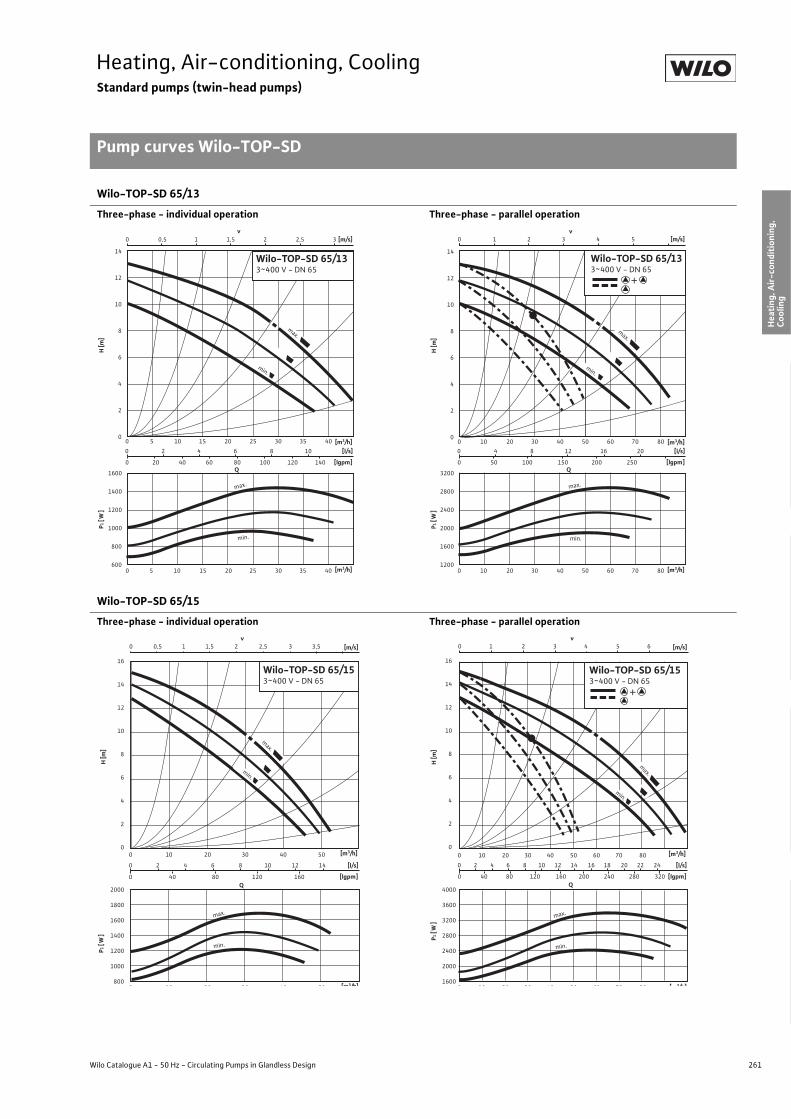
261
Heating, Air-conditioning, CoolingStandard pumps (twin-head pumps)
Pump curves Wilo-TOP-SD
Wilo Catalogue A1 - 50 Hz - Circulating Pumps in Glandless Design
Hea
ting,
Air-
cond
ition
ing,
Co
olin
gSe
cond
ary
Hot W
ater
Circ
ulat
ion
Sola
r The
rmal
, Geo
ther
mal
En
ergy
Sys
tem
sSe
rvic
e/Ac
cess
orie
s, S
yste
ms
Switc
hgea
rs a
nd C
ontr
ol
Dev
ices
Pum
p M
anag
emen
t Sys
tem
s
Wilo-TOP-SD 65/13
Three-phase - individual operation Three-phase - parallel operation
Wilo-TOP-SD 65/15
Three-phase - individual operation Three-phase - parallel operation
0 2 4 6 8 10
0 20 40 60 80 100 120 140
0 0,5 1 1,5 2 2,5 3
0 5 10 15 20 25 30 35 40
0 5 10 15 20 25 30 35 40
v[m/s]
Q[lgpm]
1600
1400
1200
1000
800
600
14
12
10
8
6
4
2
0
[l/s]
min.
max.
min.
max.
P 1[W
]H
[m]
[m3/h]
[m3/h]
Wilo-TOP-SD 65/133~400 V - DN 65
3200
2800
2400
2000
1600
1200
0 4 8 12 16 20
0 50 100 150 200 250
0 1 2 3 4 5
0 10 20 30 40 50 60 70 80
0 10 20 30 40 50 60 70 80
v[m/s]
Q[lgpm]
14
12
10
8
6
4
2
0
[l/s]
min.
max.
min.
max.
P1[W
]H
[m]
[m3/h]
[m3/h]
+
Wilo-TOP-SD 65/133~400 V - DN 65
2000
1800
1600
1400
1200
1000
800
16
14
12
10
8
6
4
2
0
v0 0,5 1 1,5 2 2,5 3 3,5
0 2 4 6 8 10 12 14
0 40 80 120 160 [lgpm]
[l/s]
0 10 20 30 40 50
Q
[m/s]
min.
max.
max.
min.
0 10 20 30 40 50
P 1[W
]H
[m]
[m3/h]
[m3/h]
Wilo-TOP-SD 65/153~400 V - DN 65
4000
3600
3200
2800
2400
2000
1600
16
14
12
10
8
6
4
2
0
0 2 4 6 8 10 12 14 16 18 20 22 24
0 40 80 120 160 200 240 280 320 [lgpm]
[l/s]
0 10 20 30 40 50 60 70 80
Q
min.
max.
max.
min.
v0 1 2 3 4 5 6 [m/s]
0 10 20 30 40 50 60 70 80
P1[W
]H
[m]
[m3/h]
[ 3/h]
+
Wilo-TOP-SD 65/153~400 V - DN 65

262 Subject to change without prior notice 09/2007 WILO AG
Heating, Air-conditioning, CoolingStandard pumps (twin-head pumps)
Pump curves Wilo-TOP-SD
Wilo-TOP-SD 80/7
AC - individual operation AC - parallel operation
Wilo-TOP-SD 80/10
Three-phase - individual operation Three-phase - parallel operation
0
1
2
3
4
5
6
7
1000
1200
1400
1600
1800
2000
2200
0 10 20 30 40 50 60 70
0 10 20 30 40 50 60 70
0 3 6 9 12 15 18 21
0 1 2 3v
Q
[m3/h]
[m3/h]
[m/s]
[l/s]
H [m
]P 1
[W]
min.
max.
max.
min.
+
Wilo-TOP-SD 80/71~230 V - DN 80
0
1
2
3
4
5
6
7
1000
1200
1400
1600
1800
2000
2200
0 10 20 30 40 50 60 70
0 10 20 30 40 50 60 70
0 3 6 9 12 15 18 21
0 1 2 3v
Q
[m3/h]
[m3/h]
[m/s]
[l/s]
H [m
]P 1
[W]
min.
max.
max.
min.
+
Wilo-TOP-SD 80/71~230 V - DN 80
1800
1600
1400
1200
1000
800
12
11
10
9
8
7
6
5
4
3
2
1
0
v0 1 2 3 4
0 4 8 12 16 20
0 50 100 150 200 250 [lgpm]
[l/s]
0 20 40 60 80
Q
[m/s]
min.
max.
max.
0 20 40 60 80
min.
P 1[W
]H
[m]
[m3/h]
[m3/h]
Wilo-TOP-SD 80/103~400 V - DN 80
3600
3200
2800
2400
2000
1600
0 4 8 12 16 20 24 28
0 50 100 150 200 250 300 350 [lgpm]
[l/s]
0 20 40 60 80 100
Q
min.
max.
v0 1 2 3 4 5 [m/s]
12
11
10
9
8
7
6
5
4
3
2
1
0
max.
min.
0 20 40 60 80 100
P1[W
]H
[m]
[m3/h]
[m3/h]
+
Wilo-TOP-SD 80/103~400 V - DN 80

263
Heating, Air-conditioning, CoolingStandard pumps (twin-head pumps)
Terminal diagrams, motor data Wilo-TOP-SD
Wilo Catalogue A1 - 50 Hz - Circulating Pumps in Glandless Design
Hea
ting,
Air-
cond
ition
ing,
Co
olin
gSe
cond
ary
Hot W
ater
Circ
ulat
ion
Sola
r The
rmal
, Geo
ther
mal
En
ergy
Sys
tem
sSe
rvic
e/Ac
cess
orie
s, S
yste
ms
Switc
hgea
rs a
nd C
ontr
ol
Dev
ices
Pum
p M
anag
emen
t Sys
tem
s
Terminal diagram A/motor protection A Terminal diagram B/motor protection B
Mains connection 1~230 V, 50 Hz Mains connection3~400 V, 50 Hz3~230 V, 50 Hz (with optional switching plug 3~230 V)
Internal protection against unacceptably high winding temperatures
Triggering: Internal interruption of motor voltageReset: Automatic after motor has cooled down
Internal protection against unacceptably high winding temperatures
Triggering: Internal interruption of a motor phaseReset: Disconnect mains voltage, allow motor to cool down,
switch mains voltage back on
Terminal diagram C/motor protection C Terminal diagram D/motor protection D
Mains connection 1~230 V, 50 Hz Mains connection3~400 V, 50 Hz3~230 V, 50 Hz (with optional switching plug 3~230 V)
WSK = thermal winding contactFull motor protection in all speed stages with optional Wilo-SK 602/ Wilo-SK 622 relay or other switchgears/control devices with WSK connection option
Triggering: External tripping at switchgear/control deviceReset: Manual reset at switchgear/control device necessary
(circuit diagram with SK 602/622 see “Service/accessories”)
Full motor protection with integrated trip electronics in terminal box for all speed stages
Triggering: All-pole shutdown of motor by integrated tripping electronics
Reset: Manual reset at terminal box necessary
Load capacity of the potential-free NC contact as per VDI 3814 for the collective fault signal (SSM) 1 A, 250 V ~Function see “Pump management Wilo-Control, Planning guide”
Terminal diagram E/motor protection E
Mains connection 1~230 V, 50 HzFull motor protection with integrated trip electronics in terminal box for all speed stages.Triggering: All-pole shutdown of motor by integrated
automatic trippingReset: Manual reset at terminal box necessary
Load capacity of the potential-free NC contact as per 3814 only for collective fault signal (SSM) 1 A, 250 V~Function see “Pump management Wilo-Control, Planning guide”
L NPE
NL
L1 L2PE
L2
L3
L3L1
L NPE
NL
WSK
WSK
L1 L2 L3PE
L1 L2 L3
SSM
SSM
C2 N LPEC1
C1SSM LC2 N
SSM

264 Subject to change without prior notice 09/2007 WILO AG
Heating, Air-conditioning, CoolingStandard pumps (twin-head pumps)
Terminal diagrams, motor data Wilo-TOP-SD
Motor data
Wilo-TOP-SD... Nominal power
Stage/speed Power consumption
Current at Capacitor Motorprotection
Threaded cableconnection
Terminaldiagram1~230 V 3~400 V 3~230 V
P2 n P1 I – – PG –[W] [1/min] [W] [A] �F/VDB] – – –
30/5(1-phase motor) 50
max. 2320 1640
min. 1200
100 - 140 75 - 110
55 - 75
0.650.550.35
– – 3.7/400 A 1 x 13.5 A
30/5(3-phase motor) 50
max. 2650 2190
min. 1890
85 - 150 55 - 100
40 - 75–
0.400.200.15
0.650.350.25
– B 1 x 13.5 B
32/7(1-phase motor) 90
max. 2600 2300
min. 1800
140 - 195110 - 175 85 - 120
0.950.870.62
– – 5/400 A 1 x 13.5 A
32/7(3-phase motor) 90
max. 2600 2100
min. 1750
120 - 200 85 - 130
65 - 90–
0.450.250.17
0.780.430.30
– B 1 x 13.5 B
32/10(1-phase motor) 180
max. 2600 2500
min. 2300
260 - 410210 - 395185 - 340
2.051.951.75
– – 8/400 C 2 x 13.5 C
32/10(3-phase motor) 180
max. 2600 2200
min. 1800
210 - 400160 - 280130 - 200
–0.790.490.35
1.370.840.61
– D 2 x 13.5 D
40/3(1-phase motor) 70
max. 2660 2340
min. 1710
145 - 180 95 - 150 70 - 110
0.850.750.55
– – 5/400 A 1 x 13.5 A
40/3(3-phase motor) 70
max. 2610 2120
min. 1810
95 - 160 60 - 105
40 -75–
0.400.200.15
0.650.350.25
– B 1 x 13.5 B
40/7(1-phase motor) 180
max. 2650 2450
min. 2200
250 - 390220 - 380200 - 330
1.931.881.70
– – 8/400 C 2 x 13.5 C
40/7(3-phase motor) 180
max. 2600 2100
min. 1800
220 - 370165 - 260130 - 185
–0.760.470.33
1.310.810.57
– D 2 x 13.5 D
40/10(1-phase motor) 350 max. 2850
min. 2500440 - 650340 - 620
3.203.00 – – 16/400 E 2 x 13.5 E
40/10(3-phase motor) 350
max. 2800 2500
min. 2200
300 - 585230 - 465200 - 365
–1.170.820.65
2.021.431.12
– D 2 x 13.5 D
40/15(1-phase motor) 570 max. 2800
min. 2500 615- 945415- 800
4.574.20 – – 25/400 E 2 x 13.5 E
40/15(3-phase motor) 570
max. 2800 2500
min. 2200
500 - 905380 - 720330- 585
–1.841.301.05
3.192.251.82
– D 2 x 13.5 D
50/7(1-phase motor) 350 max. 2850
min. 2300420 - 650315 - 600
3.203.00 – – 16/400 E 2 x 13.5 E
50/7(3-phase motor) 350
max. 2800 2450
min. 2150
360 - 625290 - 495245 - 380
–1.230.870.68
2.131.511.17
– D 2 x 13.5 D
50/10(1-phase motor) 450 max. 2700
min. 2500540 - 860390 - 800
4.003.80 – – 25/400 E 2 x 13.5 E
50/10(3-phase motor) 450
max. 2700 2300
min. 2000
450 - 880330 - 680280 - 500
–1.731.200.89
3.002.091.54
– D 2 x 13.5 D
Always refer to name plate data!Current I: Onsite thermal overload settings.
ATTENTION:3~230 V only with optional switching plug (accessories)

265
Heating, Air-conditioning, CoolingStandard pumps (twin-head pumps)
Terminal diagrams, motor data Wilo-TOP-SD
Wilo Catalogue A1 - 50 Hz - Circulating Pumps in Glandless Design
Hea
ting,
Air-
cond
ition
ing,
Co
olin
gSe
cond
ary
Hot W
ater
Circ
ulat
ion
Sola
r The
rmal
, Geo
ther
mal
En
ergy
Sys
tem
sSe
rvic
e/Ac
cess
orie
s, S
yste
ms
Switc
hgea
rs a
nd C
ontr
ol
Dev
ices
Pum
p M
anag
emen
t Sys
tem
s
50/15(3-phase motor) 1100
max. 2800 2650
min. 2300
1070 - 1600 840 - 1290 720 - 1030
–3.102.251.85
5.353.903.20
– D 2 x 13.5 D
65/10(1-phase motor) 570 max. 2800
min. 2500830 - 940690 - 840
4.404.20 – – 25/400 E 2 x 13.5 E
65/10(3-phase motor) 570
max. 2800 2500
min. 2150
620 - 960480 - 760400 - 600
–1.941.371.08
3.362.371.88
– D 2 x 13.5 D
65/13(3-phase motor) 1100
max. 2800 2550
min. 2250
1000 - 1450 810 - 1180
700 - 960–
2.932.101.74
5.073.643.00
– D 2 x 13.5 D
65/15(3-phase motor) 1300
max. 2850 2650
min. 2400
1170 - 1685 925 - 1425 815 - 1210
–3.412.532.18
5.914.383.78
– D 2 x 13.5 D
80/7(1-phase motor) 570 max. 2650
min. 2200960 - 1030860 - 920
4.804.60 – – 25/400 E 2 x 13.5 E
80/10(3-phase motor) 1100
max. 2800 2500
min. 2150
1270 - 16851040 - 1390 895 - 1100
–3.272.472.00
5.664.283.46
– D 2 x 13.5 D
Motor data
Wilo-TOP-SD... Nominal power
Stage/speed Power consumption
Current at Capacitor Motorprotection
Threaded cableconnection
Terminaldiagram1~230 V 3~400 V 3~230 V
P2 n P1 I – – PG –[W] [1/min] [W] [A] �F/VDB] – – –
Always refer to name plate data!Current I: Onsite thermal overload settings.
ATTENTION:3~230 V only with optional switching plug (accessories)

266 Subject to change without prior notice 09/2007 WILO AG
Heating, Air-conditioning, CoolingStandard pumps (twin-head pumps)
Dimensions, weights Wilo-TOP-SD
Dimension drawing A Dimension drawing B
Permitted installation positions, see Planning guide Permitted installation positions, see Planning guide
Dimension drawing C Dimension drawing D
Permitted installation positions, see Planning guide
Dimension drawing E Dimension drawing F - bracket diagram
Pg
b4
b1 b2
G
l 2
l 0
l 1
a2 a1
b5 Rp
R 1/8
R 1/8
l 0
l 1
l 2
b4 b5
Pg Pg
a 1a 2
b1 b2
l 0
R 1/8
R 1/8
b4 b5 b1 b2
l 1
Pg Pg Pg Pg
M10
l 2
a 1a 2
Ø D
n x Ø d
Ø k
DN
L2Ø k Ø d
L 1
1
n x Ø d 2
n x Ø d
Ø D Ø k
DN
Ø d
L
z1
50
y 1
y 2
50
18
18
18
3030
30

267
Heating, Air-conditioning, CoolingStandard pumps (twin-head pumps)
Dimensions, weights Wilo-TOP-SD
Wilo Catalogue A1 - 50 Hz - Circulating Pumps in Glandless Design
Hea
ting,
Air-
cond
ition
ing,
Co
olin
gSe
cond
ary
Hot W
ater
Circ
ulat
ion
Sola
r The
rmal
, Geo
ther
mal
En
ergy
Sys
tem
sSe
rvic
e/Ac
cess
orie
s, S
yste
ms
Switc
hgea
rs a
nd C
ontr
ol
Dev
ices
Pum
p M
anag
emen
t Sys
tem
s
Note:M10 bolt hole for attaching panel available on request for typesTOP-SD 40/3, TOP-SD 40/7, TOP-SD 40/10, TOP-SD 50/7, TOP-SD 50/10
Dimensions, weights
Wilo-TOP-SD... Pipeconnection/
nominal diameter
Thread Pump dimensions Weightabout
Dimensiondrawing
[Rp/DN] G l0 l1 l2 a1 a2 b1 b2 b4 b5 y1 y2 z1 PN 6/10 –– – [mm] [kg] –
30/5 Rp 11/4 G 2 180 105 92 150 40 112 112 120 102.5 – – – 8.0 A32/7 DN 32 – 220 115 99 172 38 126 119 123 107 – – – 14.0 B32/10 DN 32 – 220 110 102 173 60 144 143 141 141 107 11 172 18.0 C/F40/3 DN 40 – 250 135 92 156 75 126 133 123 107 108 14 154 15.0 B40/7 DN 40 – 250 135 104 193 75 150 140 153 153 108 11 172 20.5 C/F40/10 DN 40 – 250 135 111 216 75 178 172 167 167 132 35 225 29.5 C/F40/15 DN 40 – 250 125 119 258 65 200 195 172 172 132 25 225 40.0 C/F50/7 DN 50 – 280 160 111 224 82.5 179 169 167 167 132 30 225 30.5 C/F50/10 DN 50 – 280 155 111 222 82.5 198 192 176 176 157 50 228 33.5 C/F50/15 DN 50 – 340 180 120 235 120 306 296 236 236 180 50 360 63.0 C/F65/10 DN 65 – 340 185 120 253 92.5 223 209 187 187 162 25 225 46.5 C/F65/13 DN 65 – 340 185 120 253 92.5 223 209 187 187 162 25 225 50.0 C/F65/15 DN 65 – 340 185 120 283 92.5 223 209 187 187 162 25 225 55.5 C/F80/7 (1~) DN 80 – 360 205 121 253 100 249 231 199 199 180 43 240 54.5/- C/F80/10 DN 80 – 360 205 120 253 100 249 231 183.5 206 180 43 240 54.5/56.0 C/F
Flange dimensions
Wilo-TOP-SD... Flange Nominaldiameter
Pump flange dimensions Dimensiondrawing
– DN Ø D Ø d Ø kL1/kL2 Ø k n x Ø dL1/dL2 n x Ø dL –– – [mm] [pcs. x mm] [pcs. x mm] –
32/7Combination flange PN 6/10(flange PN 16, as per DIN 2533)
32 140 78 90/100 – 4 x 14 / 19 – D
32/10Combination flange 6/10(flange PN 16, in accord-ance with EN 1092-2)
32 140 76 90/100 – 4 x 14 / 19 – D
40/340/740/10
Combination flange PN 6/10(flange PN 16, as per DIN 2533)
40 150 88 100/110 – 4 x 14 / 19 - D
40/15Combination flange 6/10(flange PN 16, in accord-ance with EN 1092-2)
40 150 84 100/110 – 4 x 14 / 19 - D
50/750/10
Combination flange PN 6/10(flange PN 16, as per DIN 2533)
50 165 102 100/125 – 4 x 14 / 19 - D
50/15Combination flange PN 6/10(flange PN 16, as per EN 1092-2)
50 165 99 110/125 – 4 x 14 / 19 - D
65/1065/1365/15
Combination flange PN 6/10(flange PN 16, as per DIN 2533)
65 185 122 130/145 – 4 x 14 / 19 - D
80/7 (1~)80/10
Flange PN 6 (as per DIN 2531) 80 190 128 – 150 – 4 x 19 E
Flange PN 16(as per DIN 2533, drilled as per EN 1092-2)
80 200 138 – 160 – 8 x 19 E
n = No. of bolt holes

268 Subject to change without prior notice 09/2007 WILO AG
Heating, Air-conditioning, CoolingStandard pumps (twin-head pumps)
Series description Wilo-SE-TW
Wilo-SE
Wilo-SE-TW
ConstructionGlandless twin-head circulating pump with screwed connection or flange connection.
ApplicationHot-water heating systems for all systems, air-conditioning systems, closed cooling circuits, industrial circulating systems
Type keyExample: Wilo-SE 150-SE Standard pump (screw-end or flange-end pump)150 Type of constructionN Modified versionTW Twin-head pump (double pump)
Special features/product advantages• Can be used in heating systems and in cooling/air-conditioning sys-
tems from -20 °C to +130 °C• Twin-head pump for main/standby operation or parallel operation• Manual power adjustment with 3 speed stages• Pump housing with cataphoretic (KTL) coating for the prevention of
corrosion from condensation formation• Easy installation using combination flange PN 6/PN 10 (with DN 40)• Cable feed to terminal box possible on both sides (starting with
P1 � 250 W) with integrated strain relief device• With kit including seal for length compensation between the connec-
tion adapters from 244 mm to 250 mm. Equipped as standard for all pump types with flange connection
• Protection class IP 44
ATTENTION:For EEI classification for each pump model see Chapter “Planning guide”, Table on page 20.
SE 150-N-TW
SE 125-N-TW
SE 200-N-TW
Q[m³/h]1 2 4 6 8 10 12 14 16
H[m]
0
1
2
3
4
5
6
7
Wilo-SE-TW

269
Heating, Air-conditioning, CoolingStandard pumps (twin-head pumps)
Series description Wilo-SE-TW
Wilo Catalogue A1 - 50 Hz - Circulating Pumps in Glandless Design
Hea
ting,
Air-
cond
ition
ing,
Co
olin
gSe
cond
ary
Hot W
ater
Circ
ulat
ion
Sola
r The
rmal
, Geo
ther
mal
En
ergy
Sys
tem
sSe
rvic
e/Ac
cess
orie
s, S
yste
ms
Switc
hgea
rs a
nd C
ontr
ol
Dev
ices
Pum
p M
anag
emen
t Sys
tem
s
Equipment/function
Operating modes• Speed-stage switching
Manual functions• Selection of speed stages (3 speed stages)
Automatic functions• Full motor protection with integrated trip electronics
(optional for all types with Wilo-Protect-Module C)
External control functions• Control input “Overriding Off”
(optional for all types with Wilo-Protect-Module C)
Signal and display functions• Individual/collective fault signal (potential-free NC contact)
(optional for all types with Wilo-Protect-Module C)• Collective fault signal (potential-free NC contact)
(optional for all types with Wilo-Protect-Module C)• Individual run signal (potential-free NO contact)
(optional for all types with Wilo-Protect-Module C)• Fault signal light
(optional for all types with Wilo-Protect-Module C)
Dual pump management (twin-head pump or 2 x single-head pumps)• Main/standby operation (automatic fault-actuated switchover/time-
dependent pump alteration) (optional for all types with Wilo-Protect-Module C)
Equipment/scope of delivery• Double switchover valve in pump housing• Including seals with screw thread (loose) (only with SE 125-N-TW)• Including installation and operating instructions• Including washers for flange bolts (for nominal connection width DN 40)
Accessories• Screwed connections with screw thread• Wilo-Protect-Module C 1~230 V (2 modules required)

270 Subject to change without prior notice 09/2007 WILO AG
Heating, Air-conditioning, CoolingStandard pumps (twin-head pumps)
Technical data Wilo-SE-TW
Wilo-SE-TW...
125-N-TW 150-N-TW 200-N-TW
Approved fluids(other fluids on request)
Heating water (as per VDI 2035) • • •Water/glycol mixtures (maximum 1:1; mixtures with more than 20 % glycol content require rechecking of the pumping data)
• • •
Secondary hot water and water for food businesses as per TrinkwV 2001 – – –
Performance
Maximum delivery head [m] 5.5 4 7
Maximum flow volume [m3/h] 9 16 18
Permitted field of application
Temperature range for utilisation in HVAC systemswith maximum ambient temperature +25 °C [°C]with maximum ambient temperature +40 °C [°C]
–-20 to +130 (in short-term operation 2 h: +140)
(for utilisation with Wilo-Protect-Module C: -20 to +110)
Temperature range for utilisation in secondary hot water circulation systems
at maximum ambient temperature +40 °C [°C] – – –
Maximum permissible total hardness in secondary hot water-circulation systems [°d] – – –
Standard version for operating pressure pmax [bar] 10 6/10 6/10
Special version for operating pressure pmax [bar] – – –
Pipe connections
Screwed connection Rp 11/4 – –
Nominal connection diameter flange DN – 40 40
Flange for counter flange PN 6, standard version – – –
Counter flange for PN 16, flange, special version – – –
Combination flange PN 6/10 for counter flange PN 6 and PN 16, standard version – • •
Support-bracket mounting (with horizontal shaft only), standard version – – –
Support-bracket mounting (with horizontal shaft only), special version – • •
Electrical connection
Mains connection 1~ [V], standard version 230 230 230
Mains connection 3~ [V], standard version – – –
Mains connection 3~ [V], with optional switching plug – – –
Mains frequency [Hz] 50 50 50
• = available, – = not available

271
Heating, Air-conditioning, CoolingStandard pumps (twin-head pumps)
Technical data Wilo-SE-TW
Wilo Catalogue A1 - 50 Hz - Circulating Pumps in Glandless Design
Hea
ting,
Air-
cond
ition
ing,
Co
olin
gSe
cond
ary
Hot W
ater
Circ
ulat
ion
Sola
r The
rmal
, Geo
ther
mal
En
ergy
Sys
tem
sSe
rvic
e/Ac
cess
orie
s, S
yste
ms
Switc
hgea
rs a
nd C
ontr
ol
Dev
ices
Pum
p M
anag
emen
t Sys
tem
s
Motor/electronics
Electromagnetic compatibility – – –
Emitted interference EN 61000-6-3 EN 61000-6-3 EN 61000-6-3
Immunity to interference EN 61000-6-2 EN 61000-6-2 EN 61000-6-2
Power electronics – – –
Protection class IP 44 IP 44 IP 44
Insulation class F F F
Materials
Pump housing Cast iron (EN-GJL-200) Cast iron (EN-GJL-250) Cast iron (EN-GJL-250)
Impeller Plastic (PPE, trade name: Noryl)
Shaft Stainless steel (X46Cr13)
Bearing Metal-impregnated carbon
Minimum suction head at suction port [m]for the prevention of cavitation at water delivery temperature
50 °C 0.5 0.5 0.5
95 °C 5 5 5
110 °C 11 11 11
130 °C 24 24 24
Wilo-SE-TW...
125-N-TW 150-N-TW 200-N-TW
• = available, – = not available

272 Subject to change without prior notice 09/2007 WILO AG
Heating, Air-conditioning, CoolingStandard pumps (twin-head pumps)
Pump curves Wilo-SE-TW
Wilo-SE 125-N-TW
Individual operation Parallel operation
Wilo-SE 150-N-TW
Individual operation Parallel operation
Q[lgpm]
0
160
200
80
120
40
02 0
0
0
0
[l/s]
1
4
5
6
3
2
2
0,5
10 20
1,5
4 6
2 1 0 [m/s] v
1
4 6
max.
[m3/h]
[m3/h]
P 1[W]
H[m
]
Wilo-SE 125-N-TW1~230V - Rp 1¼
max.
max.
min.
Q[lgpm]
0
320
240
280
160
200
80
120
40
0 20
0
0
0
[l/s]
1
4
5
6
3
2
2
0,5
10 20 30
1,5 2,5 2
4 6 8
3 2 1 0 [m/s] v
1
4 6 8
max.
min.
min.
max.
P 1[W]
H[m
]
+
[m3/h]
[m3/h]
Wilo-SE 125-N-TW1~230V - Rp 1¼
H [m
]P 1
[W]
0 1 2
0
0
50
100
150
200
1
2
3
4
5
10 2 30 1 2 3 [l/s]
0 5 10 15 20 25 30 35 [Igpm]
4 5 6 7 8 9 10 [m³/h]
10 2 3 4 5 6 7 8 9 10 [m³/h]
v[m/s]
Wilo-SE 150-N-TW1~230V - DN40
Q
max.
min.
min.
max.
Q
0
320
360
240
280
160
200
80
120
40
0
0
0
0
[ l/s]
0,8
3,2
4,0
2,4
1,6
4
1
25
3 5 4
8 12 16
50
3 2 1 0 [m/s] v
2
4 0 8 12 16
max.
min.
P 1 [
W]
H [m
]
[m 3 /h]
[lgpm ]
[m 3 /h]
+
Wilo-SE 150-N-TW1~230V - DN 40
max.
min.

273
Heating, Air-conditioning, CoolingStandard pumps (twin-head pumps)
Pump curves Wilo-SE-TW
Wilo Catalogue A1 - 50 Hz - Circulating Pumps in Glandless Design
Hea
ting,
Air-
cond
ition
ing,
Co
olin
gSe
cond
ary
Hot W
ater
Circ
ulat
ion
Sola
r The
rmal
, Geo
ther
mal
En
ergy
Sys
tem
sSe
rvic
e/Ac
cess
orie
s, S
yste
ms
Switc
hgea
rs a
nd C
ontr
ol
Dev
ices
Pum
p M
anag
emen
t Sys
tem
s
Wilo-SE 200-N-TW
Individual operation Parallel operation
H [m
]P 1
[W]
[l/s]
[Igpm]
[m/s]v
Q
21,510 0,5
4
5
6
7
0
100
200
300
400
500
3
2
1
0
0 5 10 15 20 25 30 35
[m³/h]0 2 4 6 8 100 0,5 1 1,5 2 2,5 3
[m³/h]0 2 4 6 8 10
Wilo-SE 200-N-TW1~230V - DN40
max.
min.
min.
max.
H [m
]P 1
[W]
00 2 4 6 8 10 12 14 16 [m³/h]
200
100
300
400
500
[Igpm]
v
min.
max.
[m/s]43,53
3
4
2,52
2
6
7
5
1,51
1
0
00 2 4 6 8 10
Q
12 14 16
543210
2010 4030 50 600
[m³/h][l/s]
0,5
+
max.
Wilo-SE 200-N-TW1~230 V - DN40
min.
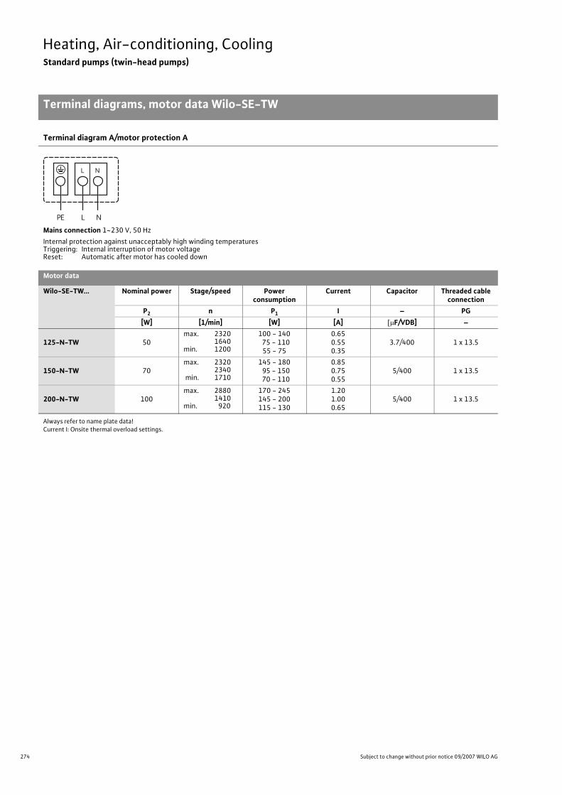
274 Subject to change without prior notice 09/2007 WILO AG
Heating, Air-conditioning, CoolingStandard pumps (twin-head pumps)
Terminal diagrams, motor data Wilo-SE-TW
Terminal diagram A/motor protection A
Mains connection 1~230 V, 50 HzInternal protection against unacceptably high winding temperaturesTriggering: Internal interruption of motor voltageReset: Automatic after motor has cooled down
Motor data
Wilo-SE-TW... Nominal power Stage/speed Power consumption
Current Capacitor Threaded cable connection
P2 n P1 I – PG[W] [1/min] [W] [A] �F/VDB] –
125-N-TW 50max. 2320
1640 min. 1200
100 - 140 75 - 110
55 - 75
0.650.550.35
3.7/400 1 x 13.5
150-N-TW 70max. 2320
2340 min. 1710
145 - 180 95 - 150 70 - 110
0.850.750.55
5/400 1 x 13.5
200-N-TW 100max. 2880
1410min. 920
170 - 245145 - 200115 - 130
1.201.000.65
5/400 1 x 13.5
Always refer to name plate data!Current I: Onsite thermal overload settings.
L NPE
NL

275
Heating, Air-conditioning, CoolingStandard pumps (twin-head pumps)
Dimensions, weights Wilo-SE-TW
Wilo Catalogue A1 - 50 Hz - Circulating Pumps in Glandless Design
Hea
ting,
Air-
cond
ition
ing,
Co
olin
gSe
cond
ary
Hot W
ater
Circ
ulat
ion
Sola
r The
rmal
, Geo
ther
mal
En
ergy
Sys
tem
sSe
rvic
e/Ac
cess
orie
s, S
yste
ms
Switc
hgea
rs a
nd C
ontr
ol
Dev
ices
Pum
p M
anag
emen
t Sys
tem
s
Dimension drawing A Dimension drawing B
Dimension drawing C
Dimensions, weights
Wilo-SE-TW... Pipe connection/
nominal diameter
Thread Pump dimensions Weightabout
Dimension drawing
[Rp/DN] G I0 l1 I2 A1 a2 b1 b2 b4 b5 - –– – [mm] [kg] –
125-N-TW Rp 1 1/4 G2 180 105 92 150 40 112 112 120 104 8.0 A
150-N-TW DN 40 – 250 135 92 156 75 126 133 123 107 15.0 B
200-N-TW DN 40 – 250 135 92 156 75 126 133 123 107 15.6 B
Flange dimensions
Wilo-SE-TW... Flange Nominal diameter Pump flange dimensions Dimension drawing
– DN Ø D Ø d Ø k n x Ø dL –– – [mm] [pcs. x mm] –
150-N-TW Flange PN 10(as per EN 1092) 40 150 84 110 4 x 19 C
200-N-TW Flange PN 10(as per EN 1092) 40 150 84 110 4 x 19 C
b4
l 2
l 0
l 1
b5 G
b1 b2 a1 a2
l 2
l 0l 1
b4 b5
b1 b2 a1a2
DN
Ø d
Ø K
Ø D
n x Ø dL

276 Subject to change without prior notice 09/2007 WILO AG
Heating, Air-conditioning, CoolingStandard pumps (twin-head pumps)
Series description Wilo-DOP
Wilo-DOP
ConstructionGlandless twin-head circulating pump with flange connection
ApplicationHot-water heating systems for all systems, industrial circulation systems
Type keyExample: Wilo-DOP 40/100 rDOP Standard twin-head pump (flange-end pump)40/ Nominal connection width100 Nominal impeller diameter [mm]r 4-stage manual switching
Options• SM1 version with special motor (depending on type at additional
charge) for 3~230 V, 50 Hz
• SM2 version with special motor (depending on type at additional charge) for 3~415 V, 50 Hz 3~440 V, 60 Hz 3~500 V, 50 Hz
Special features/product advantages• Manual power adjustment in 4 speed stages.• Pump housing with cataphoretic (KTL) coating for the prevention of
corrosion from condensation formation
ATTENTION:For EEI classification for each pump model see Chapter “Planning guide”, Table on page 20.
Q[m³/h]1 2 3 4 5 6 8 10 20 30 40 50 60 80 100
H[m]
0
1
2
3
4
5
6
7
8
Wilo-DOP
40/100 r
50/100 r
40/160 r
65/125 r
50/160 r
80/125 r
65/160 r
80/160 r
100/160 r
277
Heating, Air-conditioning, CoolingStandard pumps (twin-head pumps)
Series description Wilo-DOP
Wilo Catalogue A1 - 50 Hz - Circulating Pumps in Glandless Design
Hea
ting,
Air-
cond
ition
ing,
Co
olin
gSe
cond
ary
Hot W
ater
Circ
ulat
ion
Sola
r The
rmal
, Geo
ther
mal
En
ergy
Sys
tem
sSe
rvic
e/Ac
cess
orie
s, S
yste
ms
Switc
hgea
rs a
nd C
ontr
ol
Dev
ices
Pum
p M
anag
emen
t Sys
tem
s
Equipment/function
Operating modes• Speed-stage switching
Manual functions• Setting the speed stages: 4 speed stages
Signal and display functions• Thermal winding contact (WSK, potential-free NC contact)
Equipment/scope of delivery• Double switchover valve in pump housing• Including installation and operating instructions
Accessories• For pumps 3~400 V:
- Wilo relay SK602/SK622 or C-SK for full motor protection- Step switching equipment S2R 2.5 and S4R 2.5
• For pumps 1~230 V:- Wilo relay SK602/SK622 for full motor protection
• Mounting brackets for pump fixation
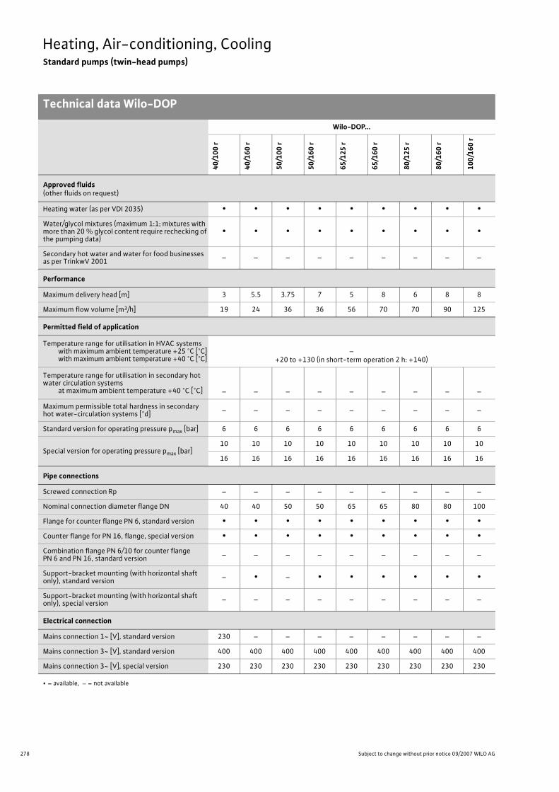
278 Subject to change without prior notice 09/2007 WILO AG
Heating, Air-conditioning, CoolingStandard pumps (twin-head pumps)
Technical data Wilo-DOP
Wilo-DOP...
40/1
00 r
40/1
60 r
50/1
00 r
50/1
60 r
65/1
25 r
65/1
60 r
80/1
25 r
80/1
60 r
100/
160
r
Approved fluids(other fluids on request)
Heating water (as per VDI 2035) • • • • • • • • •Water/glycol mixtures (maximum 1:1; mixtures with more than 20 % glycol content require rechecking of the pumping data)
• • • • • • • • •
Secondary hot water and water for food businesses as per TrinkwV 2001 – – – – – – – – –
Performance
Maximum delivery head [m] 3 5.5 3.75 7 5 8 6 8 8
Maximum flow volume [m3/h] 19 24 36 36 56 70 70 90 125
Permitted field of application
Temperature range for utilisation in HVAC systemswith maximum ambient temperature +25 °C [°C]with maximum ambient temperature +40 °C [°C]
–+20 to +130 (in short-term operation 2 h: +140)
Temperature range for utilisation in secondary hot water circulation systems
at maximum ambient temperature +40 °C [°C] – – – – – – – – –
Maximum permissible total hardness in secondary hot water-circulation systems [°d] – – – – – – – – –
Standard version for operating pressure pmax [bar] 6 6 6 6 6 6 6 6 6
Special version for operating pressure pmax [bar]10 10 10 10 10 10 10 10 10
16 16 16 16 16 16 16 16 16
Pipe connections
Screwed connection Rp – – – – – – – – –
Nominal connection diameter flange DN 40 40 50 50 65 65 80 80 100
Flange for counter flange PN 6, standard version • • • • • • • • •Counter flange for PN 16, flange, special version • • • • • • • • •Combination flange PN 6/10 for counter flange PN 6 and PN 16, standard version – – – – – – – – –
Support-bracket mounting (with horizontal shaft only), standard version – • – • • • • • •
Support-bracket mounting (with horizontal shaft only), special version – – – – – – – – –
Electrical connection
Mains connection 1~ [V], standard version 230 – – – – – – – –
Mains connection 3~ [V], standard version 400 400 400 400 400 400 400 400 400
Mains connection 3~ [V], special version 230 230 230 230 230 230 230 230 230
• = available, – = not available

279
Heating, Air-conditioning, CoolingStandard pumps (twin-head pumps)
Technical data Wilo-DOP
Wilo Catalogue A1 - 50 Hz - Circulating Pumps in Glandless Design
Hea
ting,
Air-
cond
ition
ing,
Co
olin
gSe
cond
ary
Hot W
ater
Circ
ulat
ion
Sola
r The
rmal
, Geo
ther
mal
En
ergy
Sys
tem
sSe
rvic
e/Ac
cess
orie
s, S
yste
ms
Switc
hgea
rs a
nd C
ontr
ol
Dev
ices
Pum
p M
anag
emen
t Sys
tem
s
Electrical connection (continued)
Mains connection 3~ [V], with optional switching plug – – – – – – – – –
Mains frequency [Hz] 50 50 50 50 50 50 50 50 50
Motor/electronics
Electromagnetic compatibility – – – – – – – – –
Emitted interference EN 61000-6-3
Immunity to interference EN 61000-6-2
Power electronics – – – – – – – – –
Protection class IP 42 IP 42 IP 42 IP 42 IP 42 IP 42 IP 42 IP 42 IP 42
Insulation class F F F F F F F F F
Materials
Pump housing Cast iron (EN-GJL-250)
Impeller Plastic (PP - 50% GF)Cast ironEN-GJL-
200
Shaft Stainless steel (X46 Cr13)
Bearing Metal-impregnated carbon
Minimum suction head at suction port [m]for the prevention of cavitation at water delivery temperature
50 °C 0.5 0.5 0.5 0.5 0.5 0.5 0.5 0.5 0.5
95 °C 2 5 3 5 3 5 3 5 5
110 °C 8 11 9 11 9 11 9 11 11
130 °C 21 24 22 24 22 24 22 24 24
Wilo-DOP...
40/1
00 r
40/1
60 r
50/1
00 r
50/1
60 r
65/1
25 r
65/1
60 r
80/1
25 r
80/1
60 r
100/
160
r
• = available, – = not available
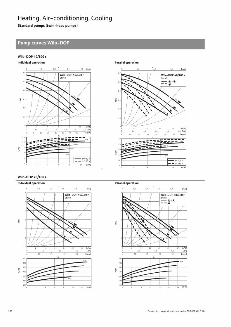
280 Subject to change without prior notice 09/2007 WILO AG
Heating, Air-conditioning, CoolingStandard pumps (twin-head pumps)
Pump curves Wilo-DOP
Wilo-DOP 40/100 r
Individual operation Parallel operation
Wilo-DOP 40/160 r
Individual operation Parallel operation
max.
Q
0 0
0 2 4 6 8 10
6
0
2
1,0
1,5
2,0
160
40
6 4
120
3~400 V 1~230 V
0,5
8
2,5
3,0
80
200
min.
10
min.
max.
0,5 0 [m/s] v
1,0 1,5 2,0
0
0
[l/s]
[lgpm]
0,5 1,0
10 5 15
1,5
20
2,0 2,5 3,0
25 30 35
[m3/h]
P 1[W]
H[m
]
[m3/h]
Wilo-DOP 40/100 rDN 40
Q
1,0 0
0 0
0
0
[l/s]
[lgpm]
0
80
1,0
[m/s]
1,0
1,5
2,0
v 2,0 3,0
240
12 4
320
4
0,5
8
2,5
3,0
2,0 3,0 4,0 5,0
400
8
16
max.
12 16
160
max.
3~400 V 1~230 V
0
min.
60 50 40 30 20 10
+
[m3/h]
P 1[W]
H[m
]
[m3/h]
Wilo-DOP 40/100 rDN 40
min
max.
Q
0,5 0
0 0
0
0
[l/s]
[lgpm]
0
2
[m/s]
2
3
4
v 1,0 2,0
350
200
6 4
300
2 6 4
1
8
5
6
1,0 2,0
10 20 30
250
400
min.
8
10
10
1,5
12
max.
min.
3,0
40
150
100 12
[m3/h]
P 1[W]
H[m
]
[m3/h]
Wilo-DOP 40/160 rDN 40
max.
Q
1,0 0
0 0
0
0
[l/s]
[lgpm]
0
4
[m/s]
2
3
4
v 2,0 4,0
700
400
12 8
600
4 1 2 8
1
16
5
6
2,0 4,0
20 40 60
500
800
min.
16
20
20
3,0
24
max.
min.
6,0
80
300
200 24 [m3/h]
P 1[W]
H[m
]
+
[m3/h]
Wilo-DOP 40/160 rDN 40
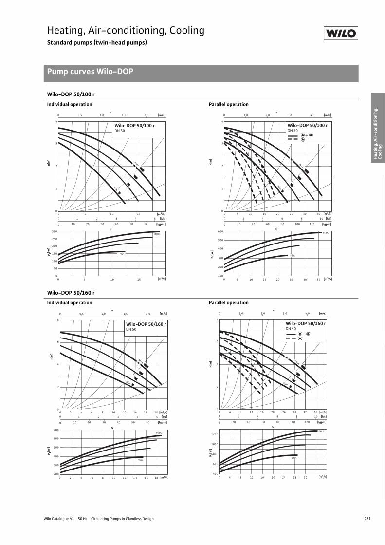
281
Heating, Air-conditioning, CoolingStandard pumps (twin-head pumps)
Pump curves Wilo-DOP
Wilo Catalogue A1 - 50 Hz - Circulating Pumps in Glandless Design
Hea
ting,
Air-
cond
ition
ing,
Co
olin
gSe
cond
ary
Hot W
ater
Circ
ulat
ion
Sola
r The
rmal
, Geo
ther
mal
En
ergy
Sys
tem
sSe
rvic
e/Ac
cess
orie
s, S
yste
ms
Switc
hgea
rs a
nd C
ontr
ol
Dev
ices
Pum
p M
anag
emen
t Sys
tem
s
Wilo-DOP 50/100 r
Individual operation Parallel operation
Wilo-DOP 50/160 r
Individual operation Parallel operation
Q
0,5 0
0 0
0
0
[l/s]
[lgpm ]
0
[m/s]
2
3
v 1,0 2,0
250
100
5
200
5
1
4
1 2
150
300
10
10
1,5
15
3
50
0 15
min.
max.
4 5
min.
max.
10 20 30 40 50 60
[m3/h]
P 1[W]
H[m
]
[m3/h]
Wilo-DOP 50/100 rDN 50
[m3/h]
P 1[W]
H[m
]
+
max.Q
1,0 0
0 0
0
0
[l/s]
[lgpm]
0
[m/s]
2
3
v 2,0 4,0
200
5
500
5
1
4
2 4
20 40
600
10
10
3,0
15
6
120
300
100 15
min.
max.
8 10
60 80 100
min.
20 25 30 35
400
20 25 30 35
+
[m3/h]
Wilo-DOP 50/100 rDN 50
Q
0,5 0
0 0
0
0
[l/s]
[lgpm]
0
[m/s]
4
6
v 1,0 2,0
400
2
600
4
2
8
1 2
10 20
500
700
10
10
1,5
12
3
300
200 12
max.
4 5
30 40
min.
4 6 8 14 16 18
min.
max.
2 6 8 1 4 1 6 18
60 50
[m3/h]
P 1[W]
H[m
]
[m3/h]
Wilo-DOP 50/160 rDN 50
Q
1,0 0
0 0
0
0
[l/s]
[lgpm]
0
[m/s]
4
6
v2,0 4,0
800
4
1200
8
2
8
2 4
1000
20
20
3,0
24
6
600
400 24
max.
8 10
8 1 2 1 6 2 8 3 2 3 6
min.
max.
4 1 2 1 6 2 8 3 2
min.
20 40 60 80 100 120
[m3/h]
P 1[W]
H[m
]
+
[m3/h]
Wilo-DOP 50/160 rDN 40

282 Subject to change without prior notice 09/2007 WILO AG
Heating, Air-conditioning, CoolingStandard pumps (twin-head pumps)
Pump curves Wilo-DOP
Wilo-DOP 65/125 r
Individual operation Parallel operation
Wilo-DOP 65/160 r
Individual operation Parallel operation
Q
0,5 0
0 0
0
0
[l/s]
[lgpm]
0
[m/s]
3
4
v 1,0
300
5
500
5
2
5
1 2
20
400
600
15
10
1,5
3
200
100 15
4 5
40
min.
10 20 25
min.
max.
20 25
1
max.
6 7
60 80
[m3/h]
P 1[W]
H[m
]
[m3/h]
Wilo-DOP 65/125 rDN 65
Q
1,0 0
0 0
0
0
[l/s]
[lgpm]
0
[m/s]
3
4
v 2,0
600
10
900
10
2
5
2 4
40
750
1200
30
20
3,0
6
450
300 30
8 1 0
80
20 40 50
min.
max.
40 50
1
min.
12 14
120 160
1050
[m3/h]
P 1[W]
H[m
]
[m3/h]
+
Wilo-DOP 65/125 rDN 65
min.
Q
0,5 0
0 0
0
0
[l/s]
[lgpm]
0
[m/s]
6
v 1,0
400
5
800
5
2
8
2
20
600
1000
15
10
1,5
4
200 15
6
40
min.
10 20 25
max.
20 25
10
60 100
2,0 2,5
30 35
min.
max.
8
80 120
30 35
4
[m3/h]
P 1[W]
H[m
]
[m3/h]
Wilo-DOP 65/160 rDN 65
Q
1,0 0
0 0
0
0
[l/s]
[lgpm]
0
[m/s]
6
v 2,0
10
10
4
40
2000
30
20
3,0
8
500 30
12
80
20 40 50
max.
40 50
20
120 200
4,0 5,0
60 70
min.
16
160 240
60 70
max.
1500
1000 min.
2
8
4
[m3/h]
P 1[W]
H[m
]
[m3/h]
+
Wilo-DOP 65/160 rDN 80

283
Heating, Air-conditioning, CoolingStandard pumps (twin-head pumps)
Pump curves Wilo-DOP
Wilo Catalogue A1 - 50 Hz - Circulating Pumps in Glandless Design
Hea
ting,
Air-
cond
ition
ing,
Co
olin
gSe
cond
ary
Hot W
ater
Circ
ulat
ion
Sola
r The
rmal
, Geo
ther
mal
En
ergy
Sys
tem
sSe
rvic
e/Ac
cess
orie
s, S
yste
ms
Switc
hgea
rs a
nd C
ontr
ol
Dev
ices
Pum
p M
anag
emen
t Sys
tem
s
Wilo-DOP 80/125 r
Individual operation Parallel operation
Wilo-DOP 80/160 r
Individual operation Parallel operation
Q
0,5 0
0 0
0
0
[l/s]
[lgpm]
0
[m/s]
4
v 1,0
5
600
5
2
6
2
20
400
800
15
10
1,5
4
200 15
6
40
min.
10 20 25
max.
20 25
10
60 100
Wilo-DOP 80/125 r DN 80
30 35
8
80 120
30 35
5
3
1
max.
min.
[m3/h]
P 1[W]
H[m
]
[m3/h]
Q
1,0 0
0 0
0
0
[l/s]
[lgpm]
0
[m/s]
4
v 2,0
10
10
2
6
4
40
750
1500
30
20
3,0
8
500 30
12
80
min.
20 40 50
max.
40 50
20
120 200
60 70
16
160 240
60 70
5
3
1
max.
min.
1250
1000
[m3/h]
P 1[W]
H[m
] [m3/h]
+
Wilo-DOP 80/125 rDN 80
Q
0,5 0
0 0
0
0
[l/s]
[lgpm]
0
[m/s]
6
v 1,0
5
800
5
3
9
2,5
25
600
1400
15
10
2,0
5
400 15
7,5
50
10 20 25
20 25
12,5
75 125
30 35
10
100 150
30 35
max.
1,5
40
min.
1200
1000 min
max.
40 [m3/h]
[m3/h]
P 1[W]
H[m
]
Wilo-DOP 80/160 rDN 80
Q
1,0 0
0 0
0
0
[l/s]
[lgpm]
0
[m/s]
6
v 2,0
10
10
3
9
5
50
2800
30
20
4,0
10
800 30
15
100
min.
20 40 50
max.
40 50
25
150 250
60 70
20
200 300
60 70
max.
3,0
80
min.
2400
2000
1600
1200
80
[m3/h]
P 1[W]
H[m
]
+
[m3/h]
Wilo-DOP 80/160 rDN 80
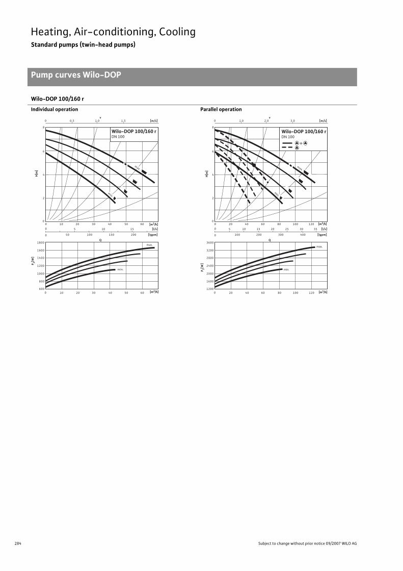
284 Subject to change without prior notice 09/2007 WILO AG
Heating, Air-conditioning, CoolingStandard pumps (twin-head pumps)
Pump curves Wilo-DOP
Wilo-DOP 100/160 r
Individual operation Parallel operation
Q
0,5 0
0 0
0
0
[l/s]
[lgpm]
0
[m/s]
6
v 1,0
1200
2
8
800
1800
20
10
5
600
50
10 30
20
40 50
10
100 150
30
1,5
60
1600
1400
min.
max.
40
4
15
200
50 60
min.
max.
1000
[m3/h]
P 1[W]
H[m
]
[m3/h]
Wilo-DOP 100/160 rDN 100
Q
1,0 0
0 0
0
0
[l/s]
[lgpm]
0
[m/s]
6
v 2,0
2400
2
8
5
1600
3600
40
20
10
1200
15
100
20 60
40
25
80 100
20
200 300
60
3,0
120
3200
2800
min.
max.
80
4
30 35
400
100 120
min.
max.
2000
[m3/h]
P 1[W]
H[m
]
+
[m3/h]
Wilo-DOP 100/160 rDN 100

285
Heating, Air-conditioning, CoolingStandard pumps (twin-head pumps)
Terminal diagrams Wilo-DOP
Wilo Catalogue A1 - 50 Hz - Circulating Pumps in Glandless Design
Hea
ting,
Air-
cond
ition
ing,
Co
olin
gSe
cond
ary
Hot W
ater
Circ
ulat
ion
Sola
r The
rmal
, Geo
ther
mal
En
ergy
Sys
tem
sSe
rvic
e/Ac
cess
orie
s, S
yste
ms
Switc
hgea
rs a
nd C
ontr
ol
Dev
ices
Pum
p M
anag
emen
t Sys
tem
s
Terminal diagram A/motor protection A Terminal diagram B/motor protection B
Mains connection 1~230 V, 50 HzWith attached capacitor
Mains connection 3~400 V, 50 Hz
WSK = thermal winding contact
Full motor protection in all speed stages with optional Wilo-SK 602/ Wilo-SK 622 relay or other Wilo AS and CR systems switchgears/con-trol devices with WSK connection option
Tripping: External tripping at switchgears/control devicesReset: Manual reset at switchgears/control devices necessary
(wiring diagram with SK 602/SK 622 see “Service/accessories”)
WSK = thermal winding contact
Full motor protection in all speed stages with optional Wilo-SK 602/ Wilo-SK 622, C-SK relay or other Wilo AS and CR systems switch-gears/control devices with WSK connection optionNote: Wilo-C-SK suitable only with 3~400 V and fluid tem-
perature up to a maximum 110 °C.Triggering: External tripping at switchgears/control devicesReset: Manual reset at switchgears/control devices necessary
(wiring diagram with SK 602/SK 622 see “Service/accessories”)
PE L1 N
L NC1
C2
WSK
L1 L2 L3
L1 L2 L3 15WSK
10 11
PE

286 Subject to change without prior notice 09/2007 WILO AG
Heating, Air-conditioning, CoolingStandard pumps (twin-head pumps)
Motor data Wilo-DOP
Motor data
Wilo-DOP... Nominal power
Stage/speed
Power consumption
Current at Capacitor Motorprotection
Threaded cable con-
nection
Terminaldiagram
1~230 V 3~400 V3~230 V (special motor)
P2 n P1 I – – PG –[W] [1/min] [W] [A] �F/VDB] – – –
40/100 r(1-phase motor)
74574130
max.130012001150
min. 1100
155 - 200140 - 190120 - 175105 - 155
1.101.050.950.85
– – 4/400 A 11 A
40/100 r(3-phase motor)
80584431
max.130012001150
min. 1000
105 - 170 85 - 140 65 - 110 50 - 85
–
0.530.380.280.22
0.920.660.480.38
– B 11 B
40/160 r(3-phase motor)
1641127048
max.130011501050
min. 850
200 - 365180 - 320155 - 260125 - 185
–
0.900.750.600.45
1.561.301.040.78
– B 13.5 B
50/100 r(3-phase motor)
1351027048
max.135013001200
min. 1100
140 - 290115 - 260 95 - 220 80 - 165
–
0.900.750.600.45
1.561.301.040.78
– B 13.5 B
50/160 r(3-phase motor)
335265190130
max.140013001200
min. 1100
310 - 635285 - 585255 - 490220 - 395
–
1.601.301.100.80
2.802.301.901.40
– B 13.5 B
65/125 r(3-phase motor)
335265190130
max.140013001200
min. 1100
310 - 635285 - 585255 - 490220 - 395
–
1.601.301.100.80
2.802.301.901.40
– B 13.5 B
65/160 r(3-phase motor)
560420280200
max.130012001050
min. 950
470 - 970430 - 880385 - 715340 - 560
–
2.201.901.501.20
3.803.302.602.10
– B 13.5 B
80/125 r(3-phase motor)
430350270200
max.135013001150
min. 1050
405 - 745360 - 685320 - 585290 - 490
–
2.21.91.51.2
3.83.32.62.1
– B 13.5 B
80/160 r(3-phase motor)
810690530370
max.140013501250
min. 1100
645 - 1330 590 - 1260 540 - 1140 495 - 930
–
3.22.82.52.2
5.54.84.33.8
– B 13.5 B
100/160 r(3-phase motor)
1080920720520
max.140013501300
min. 1200
900 - 1650800 - 1500750 - 1330650 - 1100
–
4.03.63.12.7
6.96.25.44.7
– B 13.5 B
Please consider name plate data!Current I: Default value for motor protection switch provided by customer
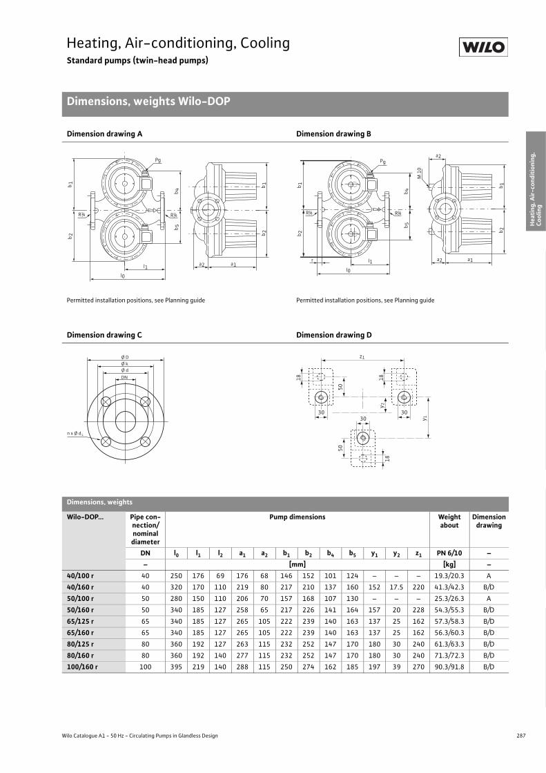
287
Heating, Air-conditioning, CoolingStandard pumps (twin-head pumps)
Dimensions, weights Wilo-DOP
Wilo Catalogue A1 - 50 Hz - Circulating Pumps in Glandless Design
Hea
ting,
Air-
cond
ition
ing,
Co
olin
gSe
cond
ary
Hot W
ater
Circ
ulat
ion
Sola
r The
rmal
, Geo
ther
mal
En
ergy
Sys
tem
sSe
rvic
e/Ac
cess
orie
s, S
yste
ms
Switc
hgea
rs a
nd C
ontr
ol
Dev
ices
Pum
p M
anag
emen
t Sys
tem
s
Dimension drawing A Dimension drawing B
Permitted installation positions, see Planning guide Permitted installation positions, see Planning guide
Dimension drawing C Dimension drawing D
Dimensions, weights
Wilo-DOP... Pipe con-nection/nominal diameter
Pump dimensions Weight about
Dimension drawing
DN l0 l1 l2 a1 a2 b1 b2 b4 b5 y1 y2 z1 PN 6/10 –– [mm] [kg] –
40/100 r 40 250 176 69 176 68 146 152 101 124 – – – 19.3/20.3 A
40/160 r 40 320 170 110 219 80 217 210 137 160 152 17.5 220 41.3/42.3 B/D
50/100 r 50 280 150 110 206 70 157 168 107 130 – – – 25.3/26.3 A
50/160 r 50 340 185 127 258 65 217 226 141 164 157 20 228 54.3/55.3 B/D
65/125 r 65 340 185 127 265 105 222 239 140 163 137 25 162 57.3/58.3 B/D
65/160 r 65 340 185 127 265 105 222 239 140 163 137 25 162 56.3/60.3 B/D
80/125 r 80 360 192 127 263 115 232 252 147 170 180 30 240 61.3/63.3 B/D
80/160 r 80 360 192 140 277 115 232 252 147 170 180 30 240 71.3/72.3 B/D
100/160 r 100 395 219 140 288 115 250 274 162 185 197 39 270 90.3/91.8 B/D
l0
l1
R 1/8 R 1/8
Pg
b1
b4
b5
b2
b1
b2
a1a2
M 1
0
R 1/8 R 1/8
Pg
l0
l1 a1a2
b 1b 2
b 1b 2
b 4b 5
a2
r
n x Ø d
Ø D Ø k
DN
Ø d
L
z1
50
y 1
y 2
50
18
18
18
3030
30

288 Subject to change without prior notice 09/2007 WILO AG
Heating, Air-conditioning, CoolingStandard pumps (twin-head pumps)
Dimensions, weights Wilo-DOP
Flange dimensions
Wilo-DOP... Flange Pipe connection/nominal diameter
Pump flange dimensions Dimensiondrawing
– DN Ø D Ø d Ø k n x Ø dL –– – [mm] [pcs. x mm] –
40/100 r 40/160 r
Flange PN 6 (as per DIN 2531) 40 130 80 100 4 x 14 CFlange PN 16(as per DIN 2533,drilled as per EN 1092-2)
40 150 88 110 4 x 19 C
50/100 r 50/160 r
Flange PN 6 (as per DIN 2531) 50 140 90 110 4 x 14 CFlange PN 16(as per DIN 2533,drilled as per EN 1092-2)
50 165 102 125 4 x 19 C
65/125 r 65/160 r
Flange PN 6 (as per DIN 2531) 65 160 110 130 4 x 14 CFlange PN 16(as per DIN 2533,drilled as per EN 1092-2)
65 185 122 145 4 x 19 C
80/125 r 80/160 r
Flange PN 6 (as per DIN 2531) 80 190 128 150 4 x 19 CFlange PN 16(as per DIN 2533,drilled as per EN 1092-2)
80 200 138 160 8 x 19 C
100/160 r
Flange PN 6 (as per DIN 2531) 100 210 148 170 4 x 19 CFlange PN 16(as per DIN 2533,drilled as per EN 1092-2)
100 220 158 180 8 x 19 C
n = No. of bolt holes

289
Heating, Air-conditioning, CoolingStandard pumps (twin-head pumps)
Wilo Catalogue A1 - 50 Hz - Circulating Pumps in Glandless Design
Hea
ting,
Air-
cond
ition
ing,
Co
olin
gSe
cond
ary
Hot W
ater
Circ
ulat
ion
Sola
r The
rmal
, Geo
ther
mal
En
ergy
Sys
tem
sSe
rvic
e/Ac
cess
orie
s, S
yste
ms
Switc
hgea
rs a
nd C
ontr
ol
Dev
ices
Pum
p M
anag
emen
t Sys
tem
s

290 Subject to change without prior notice 09/2007 WILO AG
Secondary Hot Water CirculationContents
Secondary hot water circulation
High-efficiency pumps Wilo-Stratos ECO-Z, Stratos-Z, Stratos-ZD 292
Series overview 292
Wilo-Stratos ECO-Z 292
Equipment/function 294
Series description 296
Technical data 298
Pump curves 300
Terminal diagrams, motor data 301
Dimensions, weights 302
Wilo-Stratos-Z 292
Equipment/function 294
Series description 304
Technical data 306
Pump curves 308
Terminal diagrams, motor data 311
Dimensions, weights 312
Wilo-Stratos-ZD 292
Equipment/function 314
Series description 316
Technical data 318
Pump curves 320
Terminal diagrams, motor data 321
Dimensions, weights 322
Standard pumps Wilo-Star-Z, TOP-Z, VeroLine-IP-Z 324
Series overview 324
Wilo-Star-Z (CircoStar) 324
Equipment/function 326
Series description 330
Technical data 332
Pump curves 336
Terminal diagram, motor data 338
Dimensions, weights 339
Wilo-TOP-Z 324
Equipment/function 326
Series description 342
Technical data 344
Pump curves 346
Terminal diagram, motor data 350
Dimensions, weights 352
291
Secondary Hot Water CirculationContents
Wilo Catalogue A1 - 50 Hz - Circulating Pumps in Glandless Design
Hea
ting,
Air-
cond
ition
ing,
Co
olin
gSe
cond
ary
Hot W
ater
Circ
ulat
ion
Sola
r The
rmal
, Geo
ther
mal
En
ergy
Sys
tem
sSe
rvic
e/Ac
cess
orie
s, S
yste
ms
Switc
hgea
rs a
nd C
ontr
ol
Dev
ices
Pum
p M
anag
emen
t Sys
tem
s
Standard pumps (continued) Wilo-VeroLine-IP-Z 324
Equipment/function 326
Series description 354
Technical data 356
Pump curves 358
Terminal diagram, motor data 359
Dimensions, weights 360

292 Subject to change without prior notice 09/2007 WILO AG
Secondary Hot Water CirculationHigh-efficiency pumps (single-head pumps/twin-head pumps)
Series overview Wilo-Stratos ECO-Z, Stratos-Z, Stratos-ZD
Series: Wilo-Stratos ECO-Z
> Single-head pumps:• Electronically controlled circulating pumps
with screwed connection> Application: • All versions of secondary hot water circula-
tion systems> Special features: • Can be connected to building automation
devices as version …BMS (with Building Management System)
Series: Wilo-Stratos-Z
> Single-head pumps: • Electronically controlled circulating pumps
with screwed or flanged connection> Application:• Secondary hot water circulation systems of
all kinds, hot-water heating systems of all kinds, air conditioning, closed cooling cir-cuits, industrial circulating systems
Series: Wilo-Stratos-ZD
> Twin-head pumps:• Electronically controlled circulating pumps
with flanged connection> Application:• Secondary hot water circulation systems of
all kinds, hot-water heating systems of all kinds, air conditioning, closed cooling cir-cuits, industrial circulating systems
25/1-5
BMS
0
1
2
3
4
0 0,5 1,0 1,5 2,0 Q[m³/h]
H [m
]
Wilo-Stratos ECO-Z
Seriesexten
sion:
Stratos-Z 65
/1-12
10
8
6
4
2
00 5 10 15 20 25 30 35 Q[m3/h]
H [m
]
Wilo-Stratos-Z
65/1-1250/1-9
40/1-12
40/1-8
30/1-12
25/1-8
30/1-8

293
Secondary Hot Water CirculationHigh-efficiency pumps (single-head pumps/twin-head pumps)
Series overview Wilo-Stratos ECO-Z, Stratos-Z, Stratos-ZD
Wilo Catalogue A1 - 50 Hz - Circulating Pumps in Glandless Design
Hea
ting,
Air-
cond
ition
ing,
Co
olin
gSe
cond
ary
Hot W
ater
Circ
ulat
ion
Sola
r The
rmal
, Geo
ther
mal
En
ergy
Sys
tem
sSe
rvic
e/Ac
cess
orie
s, S
yste
ms
Switc
hgea
rs a
nd C
ontr
ol
Dev
ices
Pum
p M
anag
emen
t Sys
tem
s
Series: Wilo-Stratos ECO-Z
> Product advantages:• Corrosion-resistant pump housing in red brass for systems where oxygen entry is possible• Optimal handling through front operation, variable installation positions• Automatic setback operation (Autopilot)• Automatic adjustment of the pump performance in secondary hot water circulation systems
where the flow rate is variable• Very high starting torque for secure starting (starting torque 3 x higher than conventional cir-
culating pumps)• All plastic parts that come into contact with the fluid fulfil KTW recommendations• Minimum electrical power consumption: only 5.8 Watt• Thermal insulation as standard
>Additional information: Page• Planning guide:. . . . . . . . . . . . . . . . . . . 6/29• Equipment/function:. . . . . . . . . . . . . . 294• Series description: . . . . . . . . . . . . . . . . 296• Technical data: . . . . . . . . . . . . . . . . . . . 298• Pump curves: . . . . . . . . . . . . . . . . . . . . 300• Terminal diagrams, motor data: . . . . 301• Dimensions, weights: . . . . . . . . . . . . . 302• Service/accessories: . . . . . . . . . . . . . . 393• Switchgears and control devices:. . . 417
Series: Wilo-Stratos-Z
> Product advantages:• Optimum handling resulting from front-side operation and front-side access to the terminal
room, variable installation positions, position-independent display• Combination flange PN 6/PN 10 (with DN 40 to DN 50)• System expansion through retrofittable communication modules LON, CAN, PLR, DP, etc.• Thermal insulation as standard • Corrosion-resistant pump housing in red brass for systems where oxygen entry is possible• Automatic adjustment of the pump performance in variable flow rate secondary hot water cir-
culation systems with thermostatically controlled line shutoff valves• Manual control mode allows the pump performance to be ideally adjusted to the system for
constant volume flow secondary hot water circulation systems
>Additional information: Page• Planning guide:. . . . . . . . . . . . . . . . . . . 6/22• Equipment/function:. . . . . . . . . . . . . . 294• Series description: . . . . . . . . . . . . . . . . 304• Technical data: . . . . . . . . . . . . . . . . . . . 306• Pump curves: . . . . . . . . . . . . . . . . . . . . 308• Terminal diagrams, motor data: . . . . 311• Dimensions, weights: . . . . . . . . . . . . . 312• Service/accessories: . . . . . . . . . . . . . . 393• Switchgears and control devices:. . . 417• Pump management Wilo-Control:. . 489
Series: Wilo-Stratos-ZD
> Product advantages:• Highest degrees of efficiency due to ECM technology• Optimum handling resulting from front-side operation and front-side access to the terminal room,
variable installation positions, position-independent display. Combination flange PN 6/PN 10 (with DN 32 to DN 40)
• Automatic adjustment of the pump performance in variable flow rate secondary hot water cir-culation systems with thermostatically controlled line shutoff valves
• Manual control mode allows the pump performance to be ideally adjusted to the system for constant volume flow circulation systems
• System expansion through retrofittable communication modules LON, CAN, PLR, etc.• Integrable dual pump management through retrofittable Stratos IF-Modules for:
- Main/standby operation with fault-dependent switchover- Efficiency-optimised peak-load operation
• Remote control via infrared interface (IR-Module/ IR-Monitor)
>Additional information: Page• Planning guide:. . . . . . . . . . . . . . . . . . . 6/22• Equipment/function:. . . . . . . . . . . . . . 314• Series description: . . . . . . . . . . . . . . . . 316• Technical data: . . . . . . . . . . . . . . . . . . . 318• Pump curves: . . . . . . . . . . . . . . . . . . . . 320• Terminal diagrams, motor data: . . . . 321• Dimensions, weights: . . . . . . . . . . . . . 322• Service/accessories: . . . . . . . . . . . . . . 393• Switchgears and control devices:. . . 417• Pump management Wilo-Control:. . 489

294 Subject to change without prior notice 09/2007 WILO AG
Secondary Hot Water CirculationHigh-efficiency pumps (single-head pumps)
Equipment/function Wilo-Stratos ECO-Z, Stratos-Z
Wilo-Stratos ECO-Z Wilo-Stratos-Z
Operating modes
Speed-stage switching – –
Manual control mode (n=constant) •(only Stratos ECO-Z...-BMS) •
�p-c for constant differential pressure •(only Stratos ECO-Z...-BMS) •
�p-v for variable differential pressure • •�p-T for temperature-prompted differential pres-sure
– •(programmable via IR-Module, IR-Monitor,
LON or CAN)
Manual functions
Setting the operating mode •(only Stratos ECO-Z...-BMS) •
Setting the differential-pressure setpoint • •Setting to “Autopilot” (automatic setback operation) • •Setting the pump to ON/OFF •
(only Stratos ECO-Z...-BMS) •
Setting the speed (manual setting mode) •(only Stratos ECO-Z...-BMS) •
Setting the speed stages – –
Automatic functions
Stageless power adjustment depending on the oper-ating mode • •
“Autopilot” automatic setback operation • •Deblocking function • •Soft start • •Safety control • –
Full motor protection with integrated trip electronics – •
External control functions
Control input “Overriding Off” •(only Stratos ECO-Z...-BMS)
•Possible with Stratos IF-Modules (accessory)
Control input “Overriding Min” – •Possible with Stratos IF-Modules (accessory)
Control input “Analogue In 0 - 10 V” (remote speed adjustment)
•(only Stratos ECO-Z...-BMS)
•Possible with Stratos IF-Modules (accessory)
Control input “Analogue In 0 - 10 V” (remote set-point adjustment)
•(only Stratos ECO-Z...-BMS)
•Possible with Stratos IF-Modules (accessory)
Signal and display functions
Single/collective fault signal (potential-free NC con-tact) – –
Collective fault signal (potential-free NC contact) • (only Stratos ECO-Z...-BMS) •Individual run signal (potential-free NO contact) – •
Possible with Stratos IF-Modules (accessory)
Thermal winding contact (WSK, potential-free NC contact) – –
• = available, – = not available
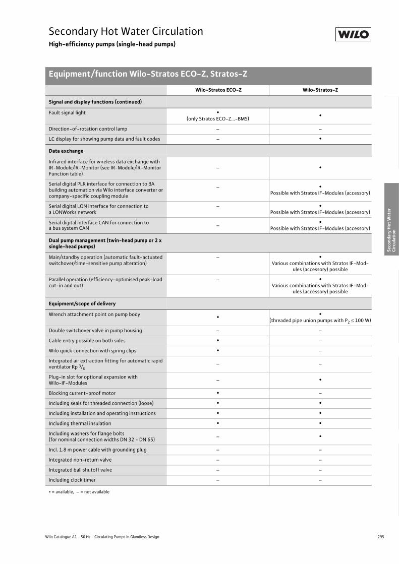
295
Secondary Hot Water CirculationHigh-efficiency pumps (single-head pumps)
Equipment/function Wilo-Stratos ECO-Z, Stratos-Z
Wilo Catalogue A1 - 50 Hz - Circulating Pumps in Glandless Design
Hea
ting,
Air-
cond
ition
ing,
Co
olin
gSe
cond
ary
Hot W
ater
Circ
ulat
ion
Sola
r The
rmal
, Geo
ther
mal
En
ergy
Sys
tem
sSe
rvic
e/Ac
cess
orie
s, S
yste
ms
Switc
hgea
rs a
nd C
ontr
ol
Dev
ices
Pum
p M
anag
emen
t Sys
tem
s
Signal and display functions (continued)
Fault signal light •(only Stratos ECO-Z...-BMS) •
Direction-of-rotation control lamp – –
LC display for showing pump data and fault codes – •
Data exchange
Infrared interface for wireless data exchange with IR-Module/IR-Monitor (see IR-Module/IR-Monitor Function table)
– •
Serial digital PLR interface for connection to BA building automation via Wilo interface converter or company-specific coupling module
– •Possible with Stratos IF-Modules (accessory)
Serial digital LON interface for connection to a LONWorks network
– •Possible with Stratos IF-Modules (accessory)
Serial digital interface CAN for connection toa bus system CAN – •
Possible with Stratos IF-Modules (accessory)
Dual pump management (twin-head pump or 2 x single-head pumps)
Main/standby operation (automatic fault-actuated switchover/time-sensitive pump alteration)
– •Various combinations with Stratos IF-Mod-
ules (accessory) possible
Parallel operation (efficiency-optimised peak-load cut-in and out)
– •Various combinations with Stratos IF-Mod-
ules (accessory) possible
Equipment/scope of delivery
Wrench attachment point on pump body • •(threaded pipe union pumps with P2 � 100 W)
Double switchover valve in pump housing – –
Cable entry possible on both sides • –
Wilo quick connection with spring clips • –
Integrated air extraction fitting for automatic rapid ventilator Rp 3/8
– –
Plug-in slot for optional expansion with Wilo-IF-Modules – •
Blocking current-proof motor • –
Including seals for threaded connection (loose) • •Including installation and operating instructions • •Including thermal insulation • •Including washers for flange bolts(for nominal connection widths DN 32 - DN 65) – •
Incl. 1.8 m power cable with grounding plug – –
Integrated non-return valve – –
Integrated ball shutoff valve – –
Including clock timer – –
Wilo-Stratos ECO-Z Wilo-Stratos-Z
• = available, – = not available

296 Subject to change without prior notice 09/2007 WILO AG
Secondary Hot Water CirculationHigh-efficiency pumps (single-head pumps)
Series description Wilo-Stratos ECO-Z
Wilo-Stratos ECO-Z
ConstructionGlandless circulating pump with screwed connection and automatic power adjustment
ApplicationSecondary hot water circulation systems and similar systems in industrial and building services
Type keyExample: Wilo-Stratos ECO-Z 25/1-5Stratos ECO High-efficiency pump (screw-end pump)-Z Secondary hot water circulation25/ Nominal connection width1-5 Nominal delivery head range [m]
Options• As version ...-BMS suitable for linkup to external monitoring units
(e.g. BA building automation or DDC installations). The Stratos ECO-Z BMS version displays as standard a collective fault signal, the function “External OFF” and the control input “0-10 V”.
Special features/product advantages• Corrosion-resistant pump housing in red brass for systems where
oxygen entry is possible• Optimal handling through front operation, variable installation posi-
tions• Automatic setback operation (Autopilot)• Automatic adjustment of the pump performance in secondary hot
water circulation systems where the flow rate is variable• Very high starting torque for secure starting (starting torque
3 x higher than conventional circulating pumps)• All plastic parts that come into contact with the fluid fulfil KTW rec-
ommendations• Minimum electrical power consumption: only 5.8 Watt• Thermal insulation as standard
25/1-5
BMS
0
1
2
3
4
5
H[m]
0 0 5 1 0 1 5 2 0 2 5 Q[m³/h]
Wilo-Stratos ECO-Z

297
Secondary Hot Water CirculationHigh-efficiency pumps (single-head pumps)
Series description Wilo-Stratos ECO-Z
Wilo Catalogue A1 - 50 Hz - Circulating Pumps in Glandless Design
Hea
ting,
Air-
cond
ition
ing,
Co
olin
gSe
cond
ary
Hot W
ater
Circ
ulat
ion
Sola
r The
rmal
, Geo
ther
mal
En
ergy
Sys
tem
sSe
rvic
e/Ac
cess
orie
s, S
yste
ms
Switc
hgea
rs a
nd C
ontr
ol
Dev
ices
Pum
p M
anag
emen
t Sys
tem
s
Equipment/function
Operating modes• Remote speed control (n=constant) (only Stratos ECO-Z...BMS)• �p-c for constant differential pressure (only Stratos ECO-Z...BMS)• �p-v for variable differential pressure
Manual functions• Selection of operating mode (only Stratos ECO-Z...BMS)• Setting the differential-pressure setpoint• Setting to “Autopilot” (automatic setback operation)• Selection Pump ON/OFF (only Stratos ECO-Z...BMS)• Selection of speed (manual speed setting) (only Stratos ECO-Z...-BMS)
Automatic functions• Stageless power adjustment depending on the operating mode• “Autopilot” automatic setback operation• Deblocking function• Soft start• Safety control
External control functions• Control input “Overriding Off” (only Stratos ECO-Z...BMS)• Control input “Analogue In 0 - 10 V” (remote speed adjustment)
(only Stratos ECO-Z...-BMS)• Control input “Analogue In 0 - 10 V” (remote setpoint adjustment)
(only Stratos ECO-Z...-BMS)
Signal and display functions• Collective fault signal (potential-free NC contact)
(only Stratos ECO-Z...-BMS)• Fault signal light (only Stratos ECO-Z...-BMS)
Equipment/scope of delivery• Wrench attachment point on pump body• Cable entry possible on both sides• Quick connection with spring clips• Blocking current-proof motor• Including seals for threaded connection (loose)• Including installation and operating instructions• Including thermal insulation
Accessories• Screwed connections

298 Subject to change without prior notice 09/2007 WILO AG
Secondary Hot Water CirculationHigh-efficiency pumps (single-head pumps)
Technical data Wilo-Stratos ECO-Z
Wilo-Stratos ECO-Z ...
25/1-525/1-5 BMS
Approved fluids (other fluids on request)
Heating water (as per VDI 2035) –
Water/glycol mixtures (maximum 1:1; mixtures with more than 20 % glycol content require rechecking of the pumping data)
–
Secondary hot water and water for food businesses as per TrinkwV 2001 •
Performance
Maximum delivery head [m] 5
Maximum flow volume [m3/h] 2.5
Permitted field of application
Temperature range for utilisation in heating, ventila-tion & air conditioning systems
at maximum ambient temperature +25 °C [°C]at maximum ambient temperature +40 °C [°C]
––
Temperature range for utilisation in secondary hot water circulation systems
at maximum ambient temperature +40 °C [°C]at maximum ambient temperature +40 °C in short-term operation 2 h [°C]
+15 to +65
–
Maximum permissible total hardness in secondary hot water-circulation systems [°d] 20
Standard version with nominal pressure, pmax [bar] 10
Special version with nominal pressure, pmax [bar] –
Pipe connections
Screwed connection Rp 1
Nominal connection diameter flange DN 25
Flange for counter flange PN 6, standard version –
Flange for counter flange PN 16, special version –
Combination flange PN 6/10 for counter flange PN 6 and PN 16, standard version –
Support-bracket mounting (with horizontal shaft only), standard version –
Support-bracket mounting (with horizontal shaft only), special version –
Electrical connection
Mains connection 1~ [V], standard version 230
Mains connection 3~ [V], standard version –
Mains connection 3~ [V], with optional switching plug –
Mains frequency [Hz] 50
• = available, – = not available

299
Secondary Hot Water CirculationHigh-efficiency pumps (single-head pumps)
Technical data Wilo-Stratos ECO-Z
Wilo Catalogue A1 - 50 Hz - Circulating Pumps in Glandless Design
Hea
ting,
Air-
cond
ition
ing,
Co
olin
gSe
cond
ary
Hot W
ater
Circ
ulat
ion
Sola
r The
rmal
, Geo
ther
mal
En
ergy
Sys
tem
sSe
rvic
e/Ac
cess
orie
s, S
yste
ms
Switc
hgea
rs a
nd C
ontr
ol
Dev
ices
Pum
p M
anag
emen
t Sys
tem
s
Motor/electronics
Electromagnetic compatibility EN 61800-3
Emitted interference EN 61000-6-3
Immunity to interference EN 61000-6-2
Power electronics Pulse-pack control
Protection class IP 44
Insulation class F
Materials
Pump housing Red brass (CC 491K) as per DIN EN 1982, as per TrinkwV 2001
Impeller Polypropylene
Shaft Stainless steel
Bearing Metal-impregnated carbon
Minimum suction head at suction port [m]for the prevention of cavitation at water delivery temperature
50 °C 0.5
95 °C 3.0
Wilo-Stratos ECO-Z ...
25/1-525/1-5 BMS
• = available, – = not available

300 Subject to change without prior notice 09/2007 WILO AG
Secondary Hot Water CirculationHigh-efficiency pumps (single-head pumps)
Pump curves Wilo-Stratos ECO-Z
Wilo-Stratos ECO-Z 25/1-5
�p-v (variable)
Wilo-Stratos ECO-Z 25/1-5 BMS Wilo-Stratos ECO-Z 25/1-5 BMS
�p-c (constant) �p-v (variable)
H [m
]
0
4
5
6
2
1
3
[m/s]0,20 0,4 0,6 0,8 1,0 1,2 1,4
0 0,5 0 0,2 0,4 0,6
0 2 4 6 8
1 1,5 2 2,5
Q[m³/h]1,51 2,520 0,5
Q[m³/h]Q[l/s]
Q[lgpm]
0
40
30
20
10
50
60
70
P 1 [W
]
p-v
max.
min.
max.
4 m 3 m 2 m
1 m
5 m
min.
Wilo-Stratos ECO-Z 25/1-51~230 V - Rp 1
H [m
]
0
4
5
6
2
1
3
[m/s]0,20 0,4 0,6 0,8 1,0 1,2 1,4
0 0,50 0,2 0,4 0,6
0 2 4 6 8
1 1,5 2 2,5
Q[m³/h]1,51 2,520 0,5
Q[m³/h]Q[l/s]
Q[lgpm]
0
40
30
20
10
50
60
70
P 1 [W
]
max.
4 m 3 m 2 m
1 m
p-c
max.
min.
min.
5 m
Wilo-Stratos ECO-Z-BMS1~230 V - Rp 1
H [m
]
0
4
5
6
2
1
3
[m/s]0,20 0,4 0,6 0,8 1,0 1,2 1,4
0 0,5 0 0,2 0,4 0,6
0 2 4 6 8
1 1,5 2 2,5
Q[m³/h]1,51 2,520 0,5
Q[m³/h]Q[l/s]
Q[lgpm]
0
40
30
20
10
50
60
70
P 1 [W
]
p-v
max.
min.
max.
4 m 3 m 2 m
1 m
5 m
min.
Wilo-Stratos ECO-Z-BMS1~230 V - Rp 1

301
Secondary Hot Water CirculationHigh-efficiency pumps (single-head pumps)
Terminal diagrams, motor data Wilo-Stratos ECO-Z
Wilo Catalogue A1 - 50 Hz - Circulating Pumps in Glandless Design
Hea
ting,
Air-
cond
ition
ing,
Co
olin
gSe
cond
ary
Hot W
ater
Circ
ulat
ion
Sola
r The
rmal
, Geo
ther
mal
En
ergy
Sys
tem
sSe
rvic
e/Ac
cess
orie
s, S
yste
ms
Switc
hgea
rs a
nd C
ontr
ol
Dev
ices
Pum
p M
anag
emen
t Sys
tem
s
Terminal diagram A
Single-phase AC motor (EM), 2-pole, 1~230 V, 50 Hz
Terminal diagram B
Motor data
Wilo-StratosECO-Z...
Speed Power consumption
Current maximum Motor protection Threaded cable connection
Terminal diagram
- p1 I - PG -[1/min] [W] [A] [-] [-] -
25/1-5 1400 - 3500 5.8 - 59 0.46not necessary
(blocking current-proof)
1 x 11 A
25/1-5 BMS 1400 - 3500 5.8 - 59 0.46not necessary
(blocking current-proof)
1 x 7 1 x 9
1 x 11B
0~10VL N PE SSM InExt. off
1~ 230 V, 50 Hz

302 Subject to change without prior notice 09/2007 WILO AG
Secondary Hot Water CirculationHigh-efficiency pumps (single-head pumps)
Dimensions, weights Wilo-Stratos ECO-Z
Dimension drawing
Dimensions, weights
Wilo-StratosECO-Z...
Pipe connection
Thread Dimensions Weight about
Rp G l0 l1 l3 l4 l5 a a2 b1 b2 b3 b4 b5
- - [mm] [kg]25/1-5 1 1 1/2 180 96 90 78 50 60 32.5 133 93.5 69 73 69 2.825/1-5 BMS 1 1 1/2 180 96 90 78 50 60 32.5 185 93.5 78 73 94 2.8
G
a
b1
b3
b2 a2
b5
I4 I5
I1
I 0
l 3
b 4

303
Secondary Hot Water CirculationHigh-efficiency pumps (single-head pumps)
Wilo Catalogue A1 - 50 Hz - Circulating Pumps in Glandless Design
Hea
ting,
Air-
cond
ition
ing,
Co
olin
gSe
cond
ary
Hot W
ater
Circ
ulat
ion
Sola
r The
rmal
, Geo
ther
mal
En
ergy
Sys
tem
sSe
rvic
e/Ac
cess
orie
s, S
yste
ms
Switc
hgea
rs a
nd C
ontr
ol
Dev
ices
Pum
p M
anag
emen
t Sys
tem
s

304 Subject to change without prior notice 09/2007 WILO AG
Secondary Hot Water CirculationHigh-efficiency pumps (single-head pumps)
Series description Wilo-Stratos-Z
Wilo-Stratos-Z
ConstructionGlandless circulating pump with screwed connection or flange con-nection, EC motor and automatic power adjustment.
ApplicationSecondary hot water circulation systems of all kinds, hot-water heat-ing systems of all kinds, air conditioning, closed cooling circuits, industrial circulating systems
Type keyExample: Wilo-Stratos-Z 40/1-8Stratos High-efficiency pump (screw-end or flange-end pump),
electronically controlledZ Single-head pump for secondary hot water circulation40/ Nominal connection width1-8 Nominal delivery head range [m]
Options• Special versions for operating pressure PN 16 (at additional charge)• Can also be utilised for 1~230 V/60 Hz
Special features/product advantages• Highest degrees of efficiency due to ECM technology• Optimum handling resulting from front-side operation and front-
side access to the terminal room, variable installation positions, posi-tion-independent display
• Combination flange PN 6/PN 10 (with DN 40 to DN 50)• Thermal insulation as standard• Corrosion-resistant pump housing in red brass for systems where
oxygen entry is possible• Automatic adjustment of the pump performance in variable flow rate
secondary hot water circulation systems with thermostatically con-trolled line shutoff valves
• Manual control mode allows the pump performance to be ideally adjusted to the system for constant volume flow secondary hot water circulation systems
• System expansion through retrofittable communication modules LON, CAN, PLR, etc.
• Remote control via infrared interface (IR-Module/ IR-Monitor)
Q[m³/h]1,2 1,6 2 4 8 12 16 20 24 28 32 36
H[m]
12
10
8
6
4
2
0
25/1-8, 30/1-8
30/1-12
40/1-12
65/1-12
50/1-9
40/1-8
Wilo-Stratos-Z

305
Secondary Hot Water CirculationHigh-efficiency pumps (single-head pumps)
Series description Wilo-Stratos-Z
Wilo Catalogue A1 - 50 Hz - Circulating Pumps in Glandless Design
Hea
ting,
Air-
cond
ition
ing,
Co
olin
gSe
cond
ary
Hot W
ater
Circ
ulat
ion
Sola
r The
rmal
, Geo
ther
mal
En
ergy
Sys
tem
sSe
rvic
e/Ac
cess
orie
s, S
yste
ms
Switc
hgea
rs a
nd C
ontr
ol
Dev
ices
Pum
p M
anag
emen
t Sys
tem
s
Equipment/function
Operating modes• Manual control mode (n=constant)• �p-c for constant differential pressure• �p-v for variable differential pressure• �p-T for temperature-controlled differential pressure (programma-
ble via IR-Module, IR-Monitor, LON or CAN)
Manual functions• Setting the operating mode• Setting the differential-pressure setpoint• Setting to “Autopilot” (automatic setback operation)• Setting the pump to ON/OFF• Setting the speed (manual setting mode)
Automatic functions• Stageless power adjustment depending on the operating mode• ”Autopilot” automatic setback operation• Deblocking function• Soft start• Full motor protection with integrated trip electronics
External control functions• Control input “Overriding Off” (possible with Stratos IF-Modules)• Control input “Overriding Min” (possible with Stratos IF-Modules)• Control input “Analogue In 0 - 10 V” (remote speed adjustment)
(possible with Stratos IF-Modules)• Control input “Analogue In 0 - 10 V” (remote setpoint adjustment)
(possible with Stratos IF-Modules)
Signal and display functions• Collective fault signal (potential-free NC contact)• Individual run signal (potential-free NO contact) (possible with
Stratos IF-Modules)• Fault signal light• LC display for showing pump data and fault codes
Data exchange• Infrared interface for wireless data exchange with IR-Module/
IR-monitor (see IR-Module/IR-Monitor Function table)• Serial digital PLR interface for connection to BA via Wilo interface
converter or company-specific coupling module (possible with Stratos IF-Modules)
• Serial digital LON interface for connection to a LONWorks network (possible with Stratos IF-Modules)
• Serial digital CAN interface for connection to a CAN bus system (possible with Stratos IF-Modules)
Dual pump management (twin-head pump or 2 x single-head pumps)
• Main/standby operation (automatic fault-actuated switchover/time-sensitive pump alteration): Various combinations with Stratos IF-Modules (accessory) possible
• Parallel operation (efficiency-optimised peak-load cut-in and out): Various combinations with Stratos IF-Modules (accessory) possible
Equipment/scope of delivery• Wrench attachment point at pump body (for threaded pipe union
pumps with P2 � 100 W)• Plug-in slot for optional expansion with Wilo-IF-Modules• Including seals for threaded connection (loose)• Including installation and operating instructions• Including thermal insulation• Including washers for flange bolts (for nominal connection widths
DN 32 - DN 65)
Accessories• Screwed connections with screw thread• Cold water insulation for pumps Wilo-Climaform• IR-Module• IR-Monitor• IF-Modules Stratos:• PLR, LON, CAN, Ext. Off, Ext. Min., SBM, Ext.Aus/SBM• Analogue interface converter AnaCon• Digital interface converter DigiCon/DigiCon-A

306 Subject to change without prior notice 09/2007 WILO AG
Secondary Hot Water CirculationHigh-efficiency pumps (single-head pumps)
Technical data Wilo-Stratos-Z
Wilo-Stratos-Z …
25/1-8 30/1-8 30/1-12 40/1-8 40/1-12 50/1-9 65/1-12
Approved fluids (other fluids on request)
Heating water (as per VDI 2035) • • • • • • •Water/glycol mixtures (maximum 1:1; mixtures with more than 20 % glycol content require rechecking of the pumping data)
• • • • • • •
Secondary hot water and water for food businesses as per TrinkwV 2001
•(excluding pumps in cast iron)
Performance
Maximum delivery head [m] 7 7 11 8 12 9 11
Maximum flow volume [m3/h] 8 8 10 13 21 24 41
Permitted field of application
Temperature range for utilisation in heating, ventila-tion & air conditioning systems
at maximum ambient temperature +25 °C [°C]at maximum ambient temperature +40 °C [°C]
–- 10 to + 110
Temperature range for utilisation in secondary hot water circulation systems
at maximum ambient temperature +40 °C [°C]at maximum ambient temperature +40 °C in short-term operation 2 h [°C]
0 to +80
–
0 to +80
–
0 to +80
–
0 to +80
–
0 to +80
–
0 to +80
–
0 to +80
–
Maximum permissible total hardness in secondary hot water-circulation systems [°d] 20 20 20 20 20 20 20
Standard version with nominal pressure, pmax [bar] 6/10 6/10 6/10 6/10 6/10 6/10 6/10
Special version with nominal pressure, pmax [bar] 16 16 16 16 16 16 16
Pipe connections
Screwed connection Rp 1 1 1/4 1 1/4 – – – –
Nominal connection diameter flange DN – – – 40 40 50 65
Flange for counter flange PN 6, standard version – – – – – – –
Flange for counter flange PN 16, special version – – – • • • •Combination flange PN 6/10 for counter flangePN 6 and PN 16, standard version – – – • • • •
Support-bracket mounting (with horizontal shaft only), standard version – – – – – – –
Support-bracket mounting (with horizontal shaft only), special version – – – – – – –
Electrical connection
Mains connection 1~ [V], standard version 230 230 230 230 230 230 230
Mains connection 3~ [V], standard version 230 230 230 230 230 230 230
Mains connection 3~ [V], with optional switching plug – – – – – – –
Mains frequency [Hz] 50/60 50/60 50/60 50/60 50/60 50/60 50/60
• = available, – = not available

307
Secondary Hot Water CirculationHigh-efficiency pumps (single-head pumps)
Technical data Wilo-Stratos-Z
Wilo Catalogue A1 - 50 Hz - Circulating Pumps in Glandless Design
Hea
ting,
Air-
cond
ition
ing,
Co
olin
gSe
cond
ary
Hot W
ater
Circ
ulat
ion
Sola
r The
rmal
, Geo
ther
mal
En
ergy
Sys
tem
sSe
rvic
e/Ac
cess
orie
s, S
yste
ms
Switc
hgea
rs a
nd C
ontr
ol
Dev
ices
Pum
p M
anag
emen
t Sys
tem
s
Motor/electronics
Electromagnetic compatibility EN 61800-3
Emitted interference EN 61000-6-3
Immunity to interference EN 61000-6-2
Power electronics Frequency converter
Protection class IP 44 IP 44 IP 44 IP 44 IP 44 IP 44 IP 44
Insulation class F F F F F F F
Materials
Pump housingRed brass (CC 491K) as per DIN EN 1982, as per TrinkwV 2001
Red brass (CC 491K) as per DIN EN 1982, as per TrinkwV 2001
Red brass (CC 491K) as per DIN EN 1982, as per TrinkwV 2001
– Cast iron (EN-GJL-250) –
Impeller Plastic (PPS - 40% GF)
Plastic (PPE), trade
name: Noryl
Shaft Stainless steel (X39CrMo17-1)
Bearing Synthetic resin-impregnated carbon
Minimum suction head at suction port [m] for the prevention of cavitation at water delivery temperature
50 °C 3 3 3 3 5 5 5
95 °C 10 10 10 10 12 12 12
110 °C 16 16 16 16 18 18 18
Wilo-Stratos-Z …
25/1-8 30/1-8 30/1-12 40/1-8 40/1-12 50/1-9 65/1-12
• = available, – = not available
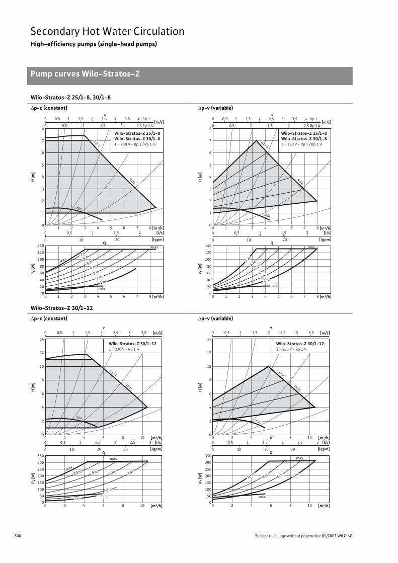
308 Subject to change without prior notice 09/2007 WILO AG
Secondary Hot Water CirculationHigh-efficiency pumps (single-head pumps)
Pump curves Wilo-Stratos-Z
Wilo-Stratos-Z 25/1-8, 30/1-8
�p-c (constant)
�p-v (variable)
Wilo-Stratos-Z 30/1-12
�p-c (constant)
�p-v (variable)
0
4
5
7
6
8
2
1
3
H [m
]
Q
[m³/h] [l/s]
[lgpm]
P 1 [W
]
0
80
60
40
20
100
120
140
Wilo-Stratos-Z 25/1-8Wilo-Stratos-Z 30/1-81 ~ 230 V - Rp 1 / Rp 1 ¼
6 8 4 0 2 5 7 3 1
[m³/h] 6 8 4 0 2 5 7 3 1
2
10 20
1,5 1 0,5
0
0
[m/s] 2 1 0 2,5 1,5 0,5
v 2 1 0 2,5 3 4 1,5 Rp 1
Rp 1 ¼
3,5 0,5
max.
max.
1 m 2 m
3 m 4 m 5 m 6 m 7 m
min.
p-c
max.
min.
0
4
5
7
6
8
2
1
3
H [m
]
Q
[l/s]
[lgpm]
P 1 [W
]
0
80
60
40
20
100
120
140
2
10 20
1,5 1 0,5
0
0
[m/s] 2 1 0 2,5 1,5 0,5
v 2 1 0 2,5 3 4 1,5 Rp 1
Rp 1¼
3,5 0,5
Wilo-Stratos-Z 25/1-8Wilo-Stratos-Z 30/1-81 ~ 230 V - Rp 1 / Rp 1 ¼
[m³/h] 6 8 4 0 2 5 7 3 1
[m³/h] 6 8 4 0 2 5 7 3 1
max.
min. 2 m 3 m 4 m 5 m
6 m 7 m
min.
max.
p-v
v0 1 2 31,50,5 2,5 3,5 [m/s]
0
8
10
12
14
4
2
6
H [m
]
[m³/h][l/s]
[lgpm]
P 1 [W
]
0
250
200
100
150
50
300
350
Wilo-Stratos-Z 30/1-121 ~ 230 V - Rp 1 ¼
80 4 1062
[m³/h]80 4 1062
1 1,5 2 32,5
10 20 30
0,5
0
0
Qmax.
max.
10 m 8 m 6 m 4 m
2 m
1 mmin.
min.
p-c
max.
v0 1 2 31,50,5 2,5 3,5 [m/s]
0
8
10
12
14
4
2
6
H [m
]
[m³/h][l/s]
[lgpm]
P 1 [W
]
0
250
200
100
150
50
300
350
Wilo-Stratos-Z 30/1-121 ~ 230 V - Rp 1 ¼
80 4 1062
[m³/h]80 4 1062
1 1,5 2 32,5
10 20 30
0,5
0
0
Qmax.
10 m 8 m 6 m 4 m
min.
min.
p-v
max.

309
Secondary Hot Water CirculationHigh-efficiency pumps (single-head pumps)
Pump curves Wilo-Stratos-Z
Wilo Catalogue A1 - 50 Hz - Circulating Pumps in Glandless Design
Hea
ting,
Air-
cond
ition
ing,
Co
olin
gSe
cond
ary
Hot W
ater
Circ
ulat
ion
Sola
r The
rmal
, Geo
ther
mal
En
ergy
Sys
tem
sSe
rvic
e/Ac
cess
orie
s, S
yste
ms
Switc
hgea
rs a
nd C
ontr
ol
Dev
ices
Pum
p M
anag
emen
t Sys
tem
s
Wilo-Stratos-Z 40/1-8
�p-c (constant)
�p-v (variable)
Wilo-Stratos-Z 40/1-12
�p-c (constant)
�p-v (variable)
0
8
9
4
2
6
7
3
1
5
H [m
]
[m³/h][l/s]
[lgpm]
Wilo-Stratos-Z 40/1-81 ~ 230 V - DN 40
1280 4 10 1462
[m³/h]1280 4 10 1462
1,51 2,52 43,53
10 20 30 40 50
0,5
0
0
Q
P 1 [W
]
0
250
200
100
150
50
300
350
v0 1 2 31,50,5 2,5 [m/s]
max.
max.
7 m 6 m 5 m 4 m 3 m
2 m
1 m min.
p-c
min.
max.
0
8
9
4
2
6
7
3
1
5
H [m
]
[m³/h][l/s]
[lgpm]
Wilo-Stratos-Z 40/1-81 ~ 230 V - DN 40
1280 4 10 1462
[m³/h]1280 4 10 1462
1,51 2,52 43,53
10 20 30 40 50
0,5
0
0
Q
P 1 [W
]
0
250
200
100
150
50
300
350
v0 1 2 31,50,5 2,5 [m/s]
min.
max.
7 m 6 m 5 m 4 m 3 m
min.
p-v
max.
v0 1 2 3 [m/s]
0
8
10
12
14
4
2
6
H [m
]
[m³/h][l/s]
[lgpm]
P 1 [W
]
0
300
200
100
400
500
Wilo-Stratos-Z 40/1-121 ~ 230 V - DN 40
12 16 1880 4 10 1462
12 16 1880 4 10 1462 [m³/h]
2 3 4 5
10 20 30 40 50 60 70
1
0
0
Qmax.
9 m8 m
10 m11 m
7 m6 m
5 m4 m
3 m2 m
1 m
max.
min.
12 m
p-c
min.
max.
v0 1 2 3 [m/s]
0
8
10
12
14
4
2
6
H [m
]
[l/s]
[lgpm]
P 1 [W
]
0
300
200
100
400
500
Wilo-Stratos-Z 40/1-121 ~ 230 V - DN 40
2 3 4 5
10 20 30 40 50 60 70
1
0
0
Q
[m³/h]12 16 1880 4 10 1462
12 16 1880 4 10 1462 [m³/h]
max.
9 m8 m10 m12 m
11 m
7 m6 m
5 m4 m
min.
max.
min.
p-v
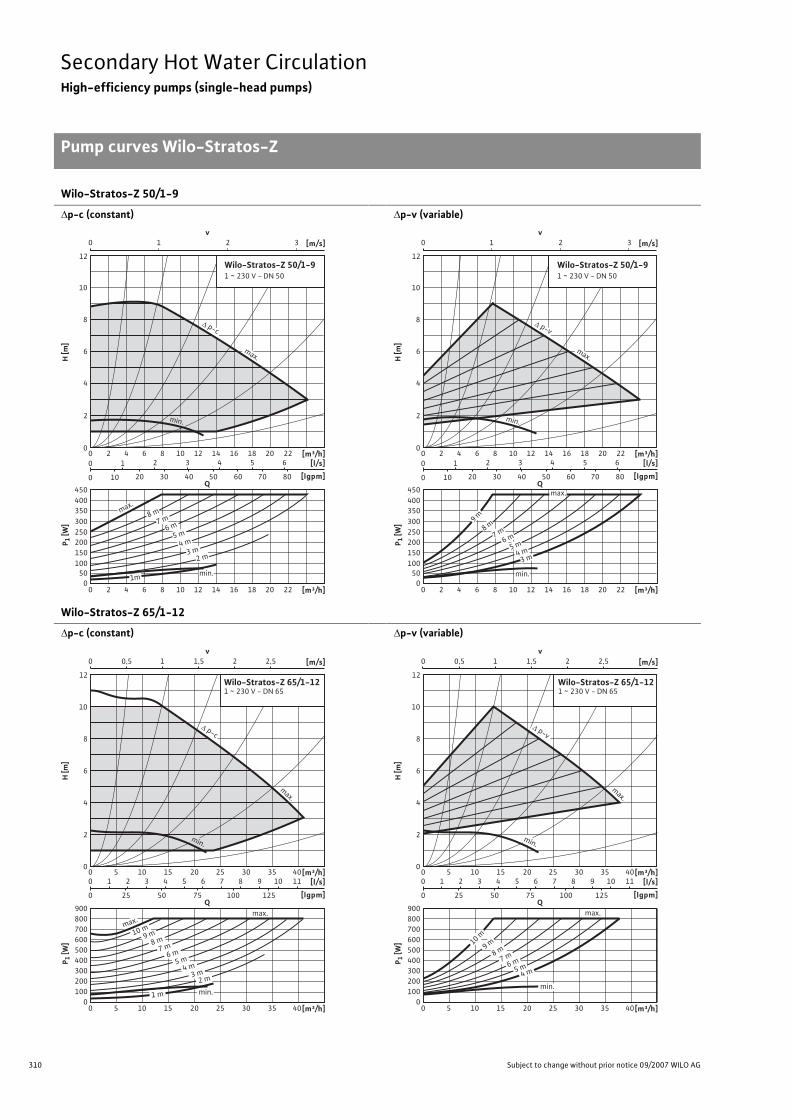
310 Subject to change without prior notice 09/2007 WILO AG
Secondary Hot Water CirculationHigh-efficiency pumps (single-head pumps)
Pump curves Wilo-Stratos-Z
Wilo-Stratos-Z 50/1-9
�p-c (constant)
�p-v (variable)
Wilo-Stratos-Z 65/1-12
�p-c (constant)
�p-v (variable)
v0 1 2 3 [m/s]
0
8
10
12
4
2
6
H [m
]
[m³/h][l/s]
[lgpm]
P 1 [W
]
0
350
10050
400450
200150
250300
12 16 18 20 2280 4 10 1462
12 16 18 20 2280 4 10 1462
2 3 4 5 6
10 20 30 40 50 60 70 80
1
0
0
Q
[m³/h]
Wilo-Stratos-Z 50/1-91 ~ 230 V - DN 50
max.8 m
7 m
min.
6 m5 m
4 m3 m
2 m
1m
min.
p-c
max.
v0 1 2 3 [m/s]
0
8
10
12
4
2
6
H [m
]
[l/s]
[lgpm]
P 1 [W
]
0
350
10050
400450
200150
250300
2 3 4 5 6
10 20 30 40 50 60 70 80
1
0
0
Q
Wilo-Stratos-Z 50/1-91 ~ 230 V - DN 50
[m³/h]12 16 18 20 2280 4 10 1462
12 16 18 20 2280 4 10 1462 [m³/h]
min.
max.
9 m
8 m7 m
6 m5 m
4 m3 m
min.
p-v
max.
v 0 1 0,5 1,5 2,5 2 [m/s]
0
12
4
2
8
10
6
H [m
]
[m³/h] [l/s]
[lgpm]
P 1 [W
]
0
500 400
200 300
100
600
900
700 800
10 0 15 20 25 30 35 40 5
[m³/h] 10 0 15 20 25 30 35 40 5
2 3 4 6 5 7 8 10 9 11
25 50 75 100 125
1
0
0
Q
Wilo-Stratos-Z 65/1-121 ~ 230 V - DN 65
max. max.
2 m
1 m
3 m 4 m 5 m 6 m 7 m 8 m
min.
9 m 10 m
min.
p-c
max.
v 0 1 0,5 1,5 2,5 2 [m/s]
0
12
4
2
8
10
6
H [m
]
[m³/h] [l/s]
[lgpm]
P 1 [W
]
0
500 400
200 300
100
600
900
700 800
10 0 15 20 25 30 35 40 5
[m³/h] 10 0 15 20 25 30 35 40 5
2 3 4 6 5 7 8 10 9 11
25 50 75 100 125
1
0
0
Q
Wilo-Stratos-Z 65/1-121 ~ 230 V - DN 65
min.
max.
4 m 5 m 6 m 7 m 8 m 9 m 10 m
min.
p-v
max.

311
Secondary Hot Water CirculationHigh-efficiency pumps (single-head pumps)
Terminal diagrams, motor data Wilo-Stratos-Z
Wilo Catalogue A1 - 50 Hz - Circulating Pumps in Glandless Design
Hea
ting,
Air-
cond
ition
ing,
Co
olin
gSe
cond
ary
Hot W
ater
Circ
ulat
ion
Sola
r The
rmal
, Geo
ther
mal
En
ergy
Sys
tem
sSe
rvic
e/Ac
cess
orie
s, S
yste
ms
Switc
hgea
rs a
nd C
ontr
ol
Dev
ices
Pum
p M
anag
emen
t Sys
tem
s
Terminal diagram
*) For additional Stratos IF-Modules, see Chapter “ Pump management sys-tems Wilo-Control”
DP: Dual pump management (2 pumps)PLR: Serial digital BA interfaceLON: Serial digital LONWorks interfaceCAN: Serial digital bus interface CANSSM Collective fault signal
(Normally closed contact as per VDI 3814, load capacity 1 A,250 V ~) Function see Chapter “Pump management Wilo-Control,Planning guide”
Motor data
Wilo-Stratos-Z... Nominal power
Speed Power consumption
Current for 1~230 V
Current for 3~230 V
Current for 3~400 V
Motor protection
Threaded cable connection
p2 n p1 I - PG[W] [1/min] [W] [A] [-] [-]
25/1-8 100 1400 - 3700 9 - 130 0.13 - 1.20 0.13 - 1.20 – integrated 1 x 7/ 1 x 9/ 1 x 13.530/1-8 100 1400 - 3700 9 - 130 0.13 - 1.20 0.13 - 1.20 – integrated 1 x 7/ 1 x 9/ 1 x 13.530/1-12 200 1600 - 4800 16 - 310 0.16 - 1.37 0.16 - 1.37 – integrated 1 x 7/ 1 x 9/ 1 x 13.540/1-8 200 1800 - 4800 18 - 310 0.17 - 1.37 0.17 - 1.37 – integrated 1 x 7/ 1 x 9/ 1 x 13.540/1-12 350 1400 - 4600 21 - 450 0.16 - 2.01 0.16 - 2.01 – integrated 1 x 7/ 1 x 9/ 1 x 13.550/1-9 350 1400 - 4100 21 - 430 0.16 - 1.88 0.16 - 1.88 – integrated 1 x 7/1 x 9/ 1 x 13.565/1-12 650 950 - 3300 38 - 800 0.28 - 3.50 0.28 - 3.50 – integrated 1 x 7/1 x 9/ 1 x 13.5
L N PE SSM L1 L3
L2 L3
L1 L2
PE SSM
DP
PLR
DP
LON
Option: IF-modules Stratos *)
PLR-module LON-module
1~230 V, 50/60 Hz
3~230 V, 50/60 Hz
DP
CAN
CAN-module
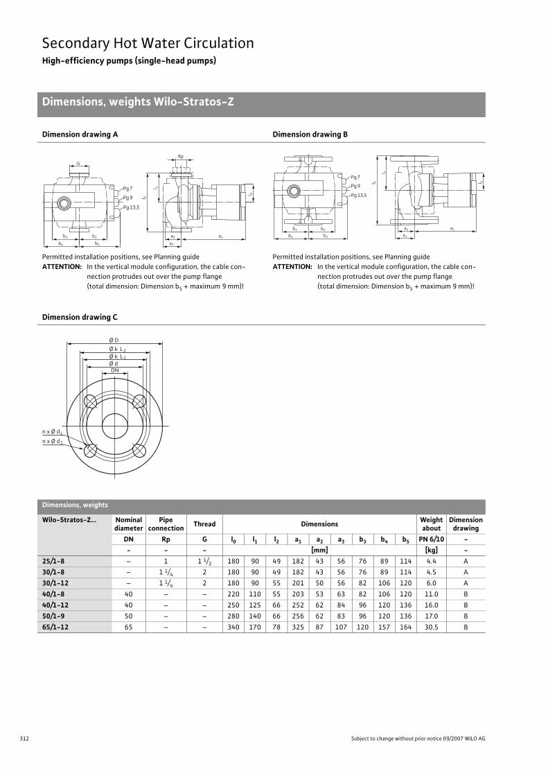
312 Subject to change without prior notice 09/2007 WILO AG
Secondary Hot Water CirculationHigh-efficiency pumps (single-head pumps)
Dimensions, weights Wilo-Stratos-Z
Dimension drawing A
Permitted installation positions, see Planning guideATTENTION: In the vertical module configuration, the cable con-
nection protrudes out over the pump flange (total dimension: Dimension b5 + maximum 9 mm)!
Dimension drawing B
Permitted installation positions, see Planning guideATTENTION: In the vertical module configuration, the cable con-
nection protrudes out over the pump flange (total dimension: Dimension b5 + maximum 9 mm)!
Dimension drawing C
Dimensions, weights
Wilo-Stratos-Z... Nominaldiameter
Pipe connection Thread Dimensions Weight
aboutDimension
drawingDN Rp G l0 l1 l2 a1 a2 a3 b3 b4 b5 PN 6/10 -- - - [mm] [kg] -
25/1-8 – 1 1 1/2 180 90 49 182 43 56 76 89 114 4.4 A30/1-8 – 1 1/4 2 180 90 49 182 43 56 76 89 114 4.5 A30/1-12 – 1 1/4 2 180 90 55 201 50 56 82 106 120 6.0 A40/1-8 40 – – 220 110 55 203 53 63 82 106 120 11.0 B40/1-12 40 – – 250 125 66 252 62 84 96 120 136 16.0 B50/1-9 50 – – 280 140 66 256 62 83 96 120 136 17.0 B65/1-12 65 – – 340 170 78 325 87 107 120 157 164 30.5 B
l 0
l 2
a2 a1
Pg 7
b3b3
G
b5b4
Pg 9
Pg 13,5
a3
Rpl 1
l 0 l 2
a2 a1
Pg 7
b3b3
b5b4
Pg 9
Pg 13,5
a3
l 1
Ø D
n x Ø d
Ø k
DN
L2Ø k Ø d
L 1
1
n x Ø d 2

313
Secondary Hot Water CirculationHigh-efficiency pumps (single-head pumps)
Dimensions, weights Wilo-Stratos-Z
Wilo Catalogue A1 - 50 Hz - Circulating Pumps in Glandless Design
Hea
ting,
Air-
cond
ition
ing,
Co
olin
gSe
cond
ary
Hot W
ater
Circ
ulat
ion
Sola
r The
rmal
, Geo
ther
mal
En
ergy
Sys
tem
sSe
rvic
e/Ac
cess
orie
s, S
yste
ms
Switc
hgea
rs a
nd C
ontr
ol
Dev
ices
Pum
p M
anag
emen
t Sys
tem
s
Flange dimensions
Wilo-Stratos-Z... Flange Nominal diameter
Pump flange dimensions Dimension drawing
- DN Ø D Ø d Ø KL1/KL2 n x Ø dL1/dL2 -[-] [-] [mm] [pcs. x mm] [-]
40/1-8 Combination flange PN 6/10(flange PN 16 as per EN 1092-2) 40 150 84 100/110 4 x 14 / 19 C
40/1-12 Combination flange PN 6/10(flange PN 16 as per EN 1092-2) 40 150 84 100/110 4 x 14 / 19 C
50/1-9 Combination flange PN 6/10(flange PN 16 as per EN 1092-2) 50 165 99 110/125 4 x 14 / 19 C
65/1-12 Combination flange PN 6/10(flange PN 16 as per EN 1092-2) 65 185 118 130/145 4 x 14 / 19 C

314 Subject to change without prior notice 09/2007 WILO AG
Secondary Hot Water CirculationHigh-efficiency pumps (twin-head pumps)
Equipment/function Wilo-Stratos-ZD
Wilo-Stratos-ZD
Operating mode
Speed-stage switching –
Manual control mode (n=constant) •�p-c for constant differential pressure •�p-v for variable differential pressure •�p-T for temperature-prompted differential pres-sure
•(programmable via IR-Module, IR-Monitor, LON or CAN)
Manual functions
Setting the operating mode •Setting the differential-pressure setpoint •Setting to “Autopilot” (automatic setback operation) •Setting the pump to ON/OFF •Setting the speed (manual setting mode) •Setting the speed stages –
Automatic functions
Stageless power adjustment depending on the oper-ating mode •
“Autopilot” automatic setback operation •Deblocking function •Soft start •Safety control –
Full motor protection with integrated trip electronics •
External control functions
Control input “Overriding Off” •Possible with Stratos IF-Modules (accessory)
Control input “Overriding Min” •Possible with Stratos IF-Modules (accessory)
Control input “Analogue In 0 - 10 V” (remote speed adjustment)
•Possible with Stratos IF-Modules (accessory)
Control input “Analogue In 0 - 10 V” (remote set-point adjustment)
•Possible with Stratos IF-Modules (accessory)
Signal and display functions
Single/collective fault signal (potential-free NC con-tact) –
Collective fault signal (potential-free NC contact) •
Individual run signal (potential-free NO contact) •Possible with Stratos IF-Modules (accessory)
Thermal winding contact (WSK, potential-free NC contact) –
Fault signal light •Direction-of-rotation control lamp –
• = available, – = not available
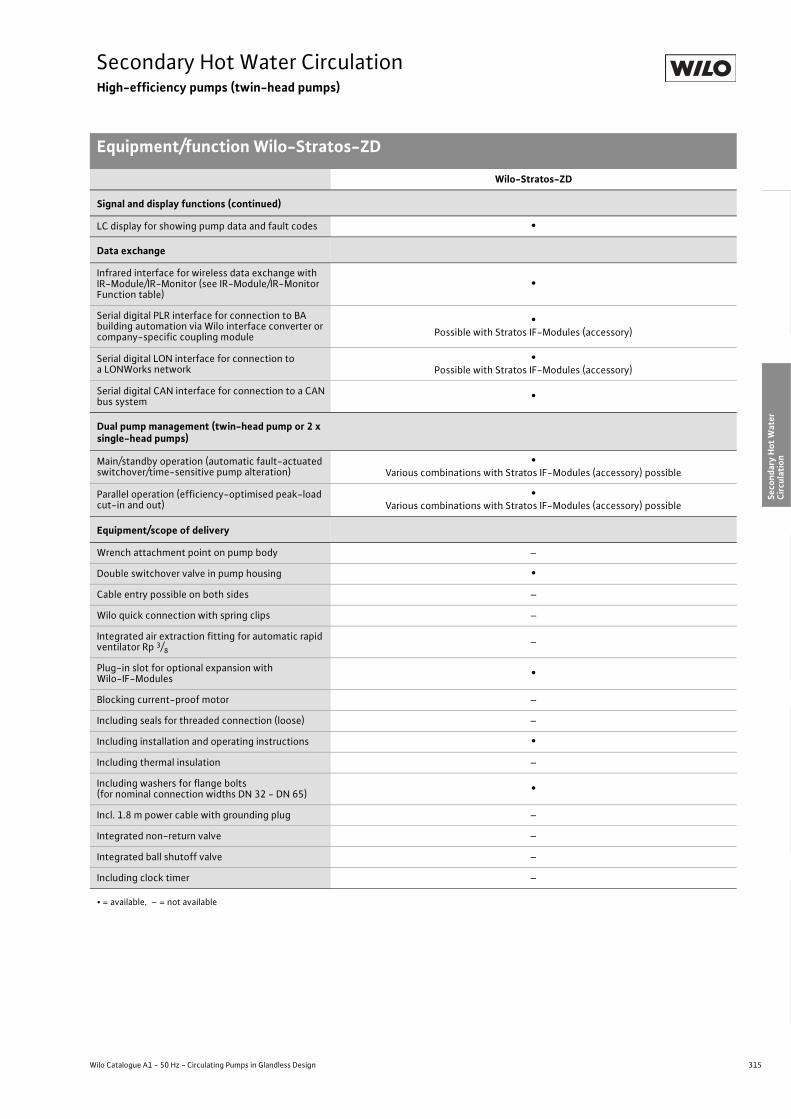
315
Secondary Hot Water CirculationHigh-efficiency pumps (twin-head pumps)
Equipment/function Wilo-Stratos-ZD
Wilo Catalogue A1 - 50 Hz - Circulating Pumps in Glandless Design
Hea
ting,
Air-
cond
ition
ing,
Co
olin
gSe
cond
ary
Hot W
ater
Circ
ulat
ion
Sola
r The
rmal
, Geo
ther
mal
En
ergy
Sys
tem
sSe
rvic
e/Ac
cess
orie
s, S
yste
ms
Switc
hgea
rs a
nd C
ontr
ol
Dev
ices
Pum
p M
anag
emen
t Sys
tem
s
Signal and display functions (continued)
LC display for showing pump data and fault codes •
Data exchange
Infrared interface for wireless data exchange with IR-Module/IR-Monitor (see IR-Module/IR-Monitor Function table)
•
Serial digital PLR interface for connection to BA building automation via Wilo interface converter or company-specific coupling module
•Possible with Stratos IF-Modules (accessory)
Serial digital LON interface for connection to a LONWorks network
•Possible with Stratos IF-Modules (accessory)
Serial digital CAN interface for connection to a CAN bus system •
Dual pump management (twin-head pump or 2 x single-head pumps)
Main/standby operation (automatic fault-actuated switchover/time-sensitive pump alteration)
•Various combinations with Stratos IF-Modules (accessory) possible
Parallel operation (efficiency-optimised peak-load cut-in and out)
•Various combinations with Stratos IF-Modules (accessory) possible
Equipment/scope of delivery
Wrench attachment point on pump body –
Double switchover valve in pump housing •Cable entry possible on both sides –
Wilo quick connection with spring clips –
Integrated air extraction fitting for automatic rapid ventilator Rp 3/8
–
Plug-in slot for optional expansion with Wilo-IF-Modules •
Blocking current-proof motor –
Including seals for threaded connection (loose) –
Including installation and operating instructions •Including thermal insulation –
Including washers for flange bolts(for nominal connection widths DN 32 - DN 65) •
Incl. 1.8 m power cable with grounding plug –
Integrated non-return valve –
Integrated ball shutoff valve –
Including clock timer –
Wilo-Stratos-ZD
• = available, – = not available

316 Subject to change without prior notice 09/2007 WILO AG
Secondary Hot Water CirculationHigh-efficiency pumps (twin-head pumps)
Series description Wilo-Stratos-ZD
Wilo-Stratos-ZD
ConstructionGlandless twin-head circulating pump with flange connection, EC motor and automatic power adjustment
ApplicationSecondary hot water circulation systems of all kinds, hot-water heat-ing systems of all kinds, air conditioning, closed cooling circuits, industrial circulating systems
Type keyExample: Wilo-Stratos-ZD 40/1-8Stratos High-efficiency pump (flange-end pump), electronically
controlledZD Twin-head pump for secondary hot water circulation40/ Nominal connection width1-8 Nominal delivery head range [m]
Options• Special versions for operating pressure PN 16 (at additional charge)• Can also be utilised for 1~230 V/60 Hz
Special features/product advantages• Highest degrees of efficiency due to ECM technology• Optimum handling resulting from front-side operation and front-
side access to the terminal room, variable installation positions, posi-tion-independent display. Combination flange PN 6/PN 10 (with DN 32 to DN 40)
• Automatic adjustment of the pump performance in variable flow rate secondary hot water circulation systems with thermostatically con-trolled line shutoff valves
• Manual control mode allows the pump performance to be ideally adjusted to the system for constant volume flow circulation systems
• System expansion through retrofittable communication modules LON, CAN, PLR, etc.
• Integrable dual pump management through retrofittable StratosIF-Modules for:- Main/standby operation with fault-dependent switchover- Efficiency-optimised peak-load operation
• Remote control via infrared interface (IR-Module/ IR-Monitor)
Q[m³/h]1 2 3 4 5 6 7 8 9 10 20
H[m]
0
1
2
3
4
5
6
7
8
9
10
Wilo-Stratos-ZD
40/1-8
32/1-12
+

317
Secondary Hot Water CirculationHigh-efficiency pumps (twin-head pumps)
Series description Wilo-Stratos-ZD
Wilo Catalogue A1 - 50 Hz - Circulating Pumps in Glandless Design
Hea
ting,
Air-
cond
ition
ing,
Co
olin
gSe
cond
ary
Hot W
ater
Circ
ulat
ion
Sola
r The
rmal
, Geo
ther
mal
En
ergy
Sys
tem
sSe
rvic
e/Ac
cess
orie
s, S
yste
ms
Switc
hgea
rs a
nd C
ontr
ol
Dev
ices
Pum
p M
anag
emen
t Sys
tem
s
Equipment/function
Operating modes• Manual control mode (n=constant)• �p-c for constant differential pressure• �p-v for variable differential pressure• �p-T for temperature-controlled differential pressure (programma-
ble via IR-Module, IR-Monitor, LON or CAN)
Manual functions• Setting the operating mode• Setting the differential-pressure setpoint• Setting to “Autopilot” (automatic setback operation)• Setting the pump to ON/OFF• Setting the speed (manual setting mode)
Automatic functions• Stageless power adjustment depending on the operating mode• “Autopilot” automatic setback operation• Deblocking function• Soft start• Full motor protection with integrated trip electronics
External control functions• Control input “Overriding Off” (possible with Stratos IF-Modules)• Control input “Overriding Min” (possible with Stratos IF-Modules)• Control input “Analogue In 0 - 10 V” (remote speed adjustment)
(possible with Stratos IF-Modules)• Control input “Analogue In 0 - 10 V” (remote setpoint adjustment)
(possible with Stratos IF-Modules)
Signal and display functions• Collective fault signal (potential-free NC contact)• Individual run signal (potential-free NO contact) (possible with
Stratos IF-Modules)• Fault signal light• LC display for showing pump data and fault codes
Data exchange• Infrared interface for wireless data exchange with IR-Module/IR-
Monitor (see IR-Module/IR-Monitor Function table)• Serial digital PLR interface for connection to BA via Wilo interface
converter or company-specific coupling module (possible with Stratos IF-Modules)
• Serial digital LON interface for connection to a LONWorks network (possible with Stratos IF-Modules)
• Serial digital CAN interface for connection to a CAN bus system (possible with Stratos IF-Modules)
Dual pump management (twin-head pump or 2 x single-head pumps)
• Main/standby operation (automatic fault-actuated switchover/time-sensitive pump alteration): Various combinations with Stratos IF-Modules (accessory) possible
• Parallel operation (efficiency-optimised peak-load cut-in and out): Various combinations with Stratos IF-Modules (accessory) possible
Equipment/scope of delivery• Double switchover valve in pump housing• Plug-in slot for optional expansion with Wilo-IF-Modules• Including installation and operating instructions• Including washers for flange bolts (for nominal connection widths
DN 40 - DN 65)
Accessories• IR-Module• IR-Monitor• IF-Modules Stratos:
PLR, LON, CAN, Ext. Off, Ext. Min., SBM, Ext.Aus/SBM• Analogue interface converter AnaCon• Digital interface converter DigiCon/DigiCon-A

318 Subject to change without prior notice 09/2007 WILO AG
Secondary Hot Water CirculationHigh-efficiency pumps (twin-head pumps)
Technical data Wilo-Stratos-ZD
Wilo-Stratos-ZD...
32/1-12 40/1-8
Approved fluids (other fluids on request)
Heating water (as per VDI 2035) • •Water/glycol mixtures (maximum 1:1; mixtures with more than 20% glycol content require rechecking of the pumping data)
• •
Secondary hot water and water for food businesses as per TrinkwV 2001
•(observe national regulations and directives)
Performance
Maximum delivery head [m] 9 8
Maximum flow volume [m3/h] 19 21
Permitted field of application
Temperature range for utilisation in heating, ventila-tion & air conditioning systems
at maximum ambient temperature +25 °C [°C]at maximum ambient temperature +40 °C [°C]
–- 10 to + 110
–- 10 to + 110
Temperature range for utilisation in secondary hot water circulation systems
at maximum ambient temperature +40 °C [°C]at maximum ambient temperature +40 °C in short-term operation 2 h [°C]
0 to +80
–
0 to +80
–
Maximum permissible total hardness in secondary hot water-circulation systems [°d] 20 20
Standard version with nominal pressure, pmax [bar] 6/10 6/10
Special version with nominal pressure, pmax [bar] 16 16
Pipe connections
Screwed connection Rp – –
Nominal connection diameter flange DN 32 40
Flange for counter flange PN 6, standard version – –
Flange for counter flange PN 16, special version • •Combination flange PN 6/10 for counter flange PN 6 and PN 16, standard version • •
Support-bracket mounting (with horizontal shaft only), standard version – –
Support-bracket mounting (with horizontal shaft only), special version – –
Electrical connection
Mains connection 1~ [V], standard version 230 230
Mains connection 3~ [V], standard version 230 230
Mains connection 3~ [V], with optional switching plug – –
Mains frequency [Hz] 50/60 50/60
• = available, – = not available

319
Secondary Hot Water CirculationHigh-efficiency pumps (twin-head pumps)
Technical data Wilo-Stratos-ZD
Wilo Catalogue A1 - 50 Hz - Circulating Pumps in Glandless Design
Hea
ting,
Air-
cond
ition
ing,
Co
olin
gSe
cond
ary
Hot W
ater
Circ
ulat
ion
Sola
r The
rmal
, Geo
ther
mal
En
ergy
Sys
tem
sSe
rvic
e/Ac
cess
orie
s, S
yste
ms
Switc
hgea
rs a
nd C
ontr
ol
Dev
ices
Pum
p M
anag
emen
t Sys
tem
s
Motor/electronics
Electromagnetic compatibility EN 61800-3 EN 61800-3
Emitted interference EN 61000-6-3 EN 61000-6-3
Immunity to interference EN 61000-6-2 EN 61000-6-2
Power electronics Frequency converter Frequency converter
Protection class IP 44 IP 44
Insulation class F F
Materials
Pump housing Cast iron (EN-GJL-250) Cast iron (EN-GJL-250)
Impeller Fibreglass-reinforced PPS Fibreglass-reinforced PPS
Shaft Stainless steel (X39CrMo17-1) Stainless steel (X39CrMo17-1)
Bearing Synthetic resin-impregnated carbon Synthetic resin-impregnated carbon
Minimum suction head at suction port [m]for the prevention of cavitation at water delivery temperature
50 °C 3 3
95 °C 10 10
110 °C 16 16
Wilo-Stratos-ZD...
32/1-12 40/1-8
• = available, – = not available

320 Subject to change without prior notice 09/2007 WILO AG
Secondary Hot Water CirculationHigh-efficiency pumps (twin-head pumps)
Pump curves Wilo-Stratos-ZD
Wilo-Stratos-ZD 32/1-12
�p-c (constant)
�p-v (variable)
Wilo-Stratos-ZD 40/1-8
�p-c (constant)
�p-v (variable)
v0 1 2 3 4 5 6 [m/s]
0
8
10
12
4
2
6
H [m
]
[m³/h][l/s]
[lgpm]
P 1 [W
]
0
300
200
100
400
500
600
700
12 16 1880 4 10 1462
12 16 1880 4 10 1462 [m³/h]
2 3 4 5
10 20 30 40 50 60
1
0
0
P1- Wilo-Stratos 32/1-12
Wilo-Stratos-ZD 32/1-121 ~ 230 V - DN 32
+
max.
1 m
9 m 8 m 7 m 6 m 5 m 4 m
2 m
3 m
min.
max.
p-c
max.
min.
v0 1 2 3 4 5 6 [m/s]
0
8
10
12
4
2
6
H [m
]
[m³/h][l/s]
[lgpm]
P 1 [W
]
0
300
200
100
400
500
600
700
12 16 1880 4 10 1462
12 16 1880 4 10 1462 [m³/h]
2 3 4 5
10 20 30 40 50 60
1
0
0
P1- Wilo-Stratos 32/1-12
Wilo-Stratos-ZD 32/1-121 ~ 230 V - DN 32
+
max.
min.
8 m 7 m 6 m 5 m 4 m
p-v
max.
min.
v0 1 2 3 4 5 6 [m/s]
0
8
10
4
2
6
7
9
3
1
5
H [m
]
[m³/h][l/s]
[lgpm]
P 1 [W
]
0
300
200
100
400
500
600
700
200 10 251552 3 4 5 6 7
10 20 30 40 50 60 70 80 90
1
0
0
[m³/h]200 10 25155
Wilo-Stratos-ZD 40/1-81 ~ 230 V - DN 40
+
Q
P1 Wilo-Stratos 40/1-8
max.
min.
max.
3 m
2 m
1 m
4 m5 m6 m7 m8 m
p-c
max.
min.
v0 1 2 3 4 5 6 [m/s]
0
8
10
4
2
6
7
9
3
1
5
H [m
]
[m³/h][l/s]
[lgpm]
P 1 [W
]
0
300
200
100
400
500
600
700
200 10 251552 3 4 5 6 7
10 20 30 40 50 60 70 80 90
1
0
0
[m³/h]200 10 25155
Wilo-Stratos-ZD 40/1-81 ~ 230 V - DN 40
+
Q
P1 Wilo-Stratos 40/1-8min.
3 m4 m5 m6 m7 m
max.
p-v
max.
min.

321
Secondary Hot Water CirculationHigh-efficiency pumps (twin-head pumps)
Terminal diagrams, motor data Wilo-Stratos-ZD
Wilo Catalogue A1 - 50 Hz - Circulating Pumps in Glandless Design
Hea
ting,
Air-
cond
ition
ing,
Co
olin
gSe
cond
ary
Hot W
ater
Circ
ulat
ion
Sola
r The
rmal
, Geo
ther
mal
En
ergy
Sys
tem
sSe
rvic
e/Ac
cess
orie
s, S
yste
ms
Switc
hgea
rs a
nd C
ontr
ol
Dev
ices
Pum
p M
anag
emen
t Sys
tem
s
Terminal diagram
*) For additional Stratos IF-Modules, see Chapter “ Pump management sys-tems” Wilo-Control”
DP: Dual pump management (2 pumps)PLR: Serial digital BA interfaceLON: Serial digital LONWorks interfaceCAN: Serial digital bus interface CANSSM Collective fault signal
(Normally closed contact as per VDI 3814, load capacity 1 A,250 V ~) Function see Chapter “Pump management Wilo-Control,Planning guide”
Motor data
Wilo-Stratos-ZD... Nominal power
Speed Power consumption
Current for 1~230 V
Current for 3~230 V
Current for 3~400 V
Motor protection
Cablescrewed connection
P2 n P1 I - PG[W] [1/min] [W] [A] - -
32/1-12 200 1600 - 4800 16 - 310 0.16 - 1.37 0.16 - 1.37 – integrated 1 x 7/1 x 9/1 x 13.540/1-8 200 1800 - 4800 18 - 310 0.17 - 1.37 0.17 - 1.37 – integrated 1 x 7/1 x 9/1 x 13.5
L N PE SSM L1 L3
L2 L3
L1 L2
PE SSM
DP
PLR
DP
LON
Option: IF-Module Stratos *)
PLR-Modul LON-Modul
1~230 V, 50/60 Hz
3~230 V, 50/60 Hz
DP
CAN
CAN-Modul

322 Subject to change without prior notice 09/2007 WILO AG
Secondary Hot Water CirculationHigh-efficiency pumps (twin-head pumps)
Dimensions, weights Wilo-Stratos-ZD
Dimension drawing A
Permitted installation positions, see Planning guideATTENTION: The cable connection protrudes above the pump
flange (total dimension: Dimension l3 + maximum 9 mm)!
Dimension drawing B
Dimensions, weights
Wilo-Stratos-ZD... Nominal diameter
Dimensions Weight approxi-mately
Dimension drawing
DN l0 l1 l3 l4 a1 a2 b1 b2 b4 b5 PN 6/10 -- [mm] [kg] -
32/1-12 32 220 110 120 106 204 57 117 130 110 130 16.5 A 40/1-8 40 220 110 120 106 200 64 125 138 115 135 17.0 A
Flange dimensions
Wilo-Stratos-ZD... Flange Nominal diameter
Pump flange dimensions Dimension drawing
- DN Ø D Ø d Ø KL1/KL2 n x Ø dL1/dL2 -- - [mm] [pcs. x mm] -
32/1-12Flange PN 6/10 (dimensioned to PN 16, in accordance with EN 1092-2)
32 140 76 90/100 4 x 14 / 19 B
40/1-8Flange PN 6/10 (dimensioned to PN 16, in accordance with EN 1092-2)
40 150 84 100/110 4 x 14 / 19 B
Pg 7
Pg 9Pg 13,5
a1b 2
b 1b5b4
l 0l 3
l 4
a2
l 1
Ø D
n x Ø d
Ø k
DN
L2Ø k Ø d
L 1
1
n x Ø d 2

323
Secondary Hot Water CirculationHigh-efficiency pumps (twin-head pumps)
Wilo Catalogue A1 - 50 Hz - Circulating Pumps in Glandless Design
Hea
ting,
Air-
cond
ition
ing,
Co
olin
gSe
cond
ary
Hot W
ater
Circ
ulat
ion
Sola
r The
rmal
, Geo
ther
mal
En
ergy
Sys
tem
sSe
rvic
e/Ac
cess
orie
s, S
yste
ms
Switc
hgea
rs a
nd C
ontr
ol
Dev
ices
Pum
p M
anag
emen
t Sys
tem
s

324 Subject to change without prior notice 09/2007 WILO AG
Secondary Hot Water CirculationStandard pumps (single-head pumps)
Series overview Wilo-Star-Z, TOP-Z, VeroLine-IP-Z
Series: Wilo-Star-Z (CircoStar)
>Single-head pumps:• Circulating pumps with screw fittings or
press fittings>Application:• Secondary hot water circulation systems
and similar systems in industrial and building services (e.g. cooling water circulation)
Series: Wilo-TOP-Z (maximum 2850 1/min)
>Single-head pumps:• Circulating pumps with screwed or flanged
connection>Application:• Secondary hot water circulation systems
and similar systems in industrial and building services (e.g. cooling water circulation)
Series: Wilo-VeroLine-IP-Z
>Single-head pumps:• Single-stage, low-pressure centrifugal
pump in Inline construction with threaded connection
>Application:• For pumping secondary hot water as well as
cold and hot water (as per VDI 2035) with-out abrasive substances in heating, cold water and cooling water installations
0 0,5 1 2 30
1
2
3
4
Star-Z 20/1
Star-Z 25/2 EM
Star-Z 25/2 DM
Star-Z 25/6 DM
Wilo-CircoStar
Q[m3/h]
H[m
]
Star-Z 15
Wilo-TOP-ZH[m
]
10
8
6
4
2
0Q[m³/h]0 10 20 30 40 50
Z80/10Z65/10Z50/7Z40/7
Z25/6Z20/4
Z30/7
Z25/30/10
0
1
0 1 2 3 4 5
2
3
4
5Wilo-VeroLine-IP-Z
IP-Z 25/6IP-Z 25/2
Q[m3/h]
H[m
]

325
Secondary Hot Water CirculationStandard pumps (single-head pumps)
Series overview Wilo-Star-Z, TOP-Z, VeroLine-IP-Z
Wilo Catalogue A1 - 50 Hz - Circulating Pumps in Glandless Design
Hea
ting,
Air-
cond
ition
ing,
Co
olin
gSe
cond
ary
Hot W
ater
Circ
ulat
ion
Sola
r The
rmal
, Geo
ther
mal
En
ergy
Sys
tem
sSe
rvic
e/Ac
cess
orie
s, S
yste
ms
Switc
hgea
rs a
nd C
ontr
ol
Dev
ices
Pum
p M
anag
emen
t Sys
tem
s
Series: Wilo-Star-Z (CircoStar)
> Product advantages:• AC pumps with electrical quick connection• All plastic parts that come into contact with the fluid fulfil KTW recommendations• Equipped as standard heat insulation for Star-Z 15...• Star-Z 15 TT with an integrated timer and thermostat, LCD with symbolic language, red button
technology and automatic detection of the thermal disinfection of the warm secondary hot water reservoir
> Additional information: Page• Planning guide: . . . . . . . . . . . . . . . . . . 6• Equipment/function: . . . . . . . . . . . . . 326• Series description: . . . . . . . . . . . . . . . . 330• Technical data: . . . . . . . . . . . . . . . . . . . 332• Pump curves: . . . . . . . . . . . . . . . . . . . . 336• Terminal diagrams, motor data: . . . . 338• Dimensions, weights: . . . . . . . . . . . . . 339• Service/accessories: . . . . . . . . . . . . . . 393• Switchgears and control devices: . . 417
Series: Wilo-TOP-Z (maximum 2850 1/min)
> Product advantages:• Manual power adjustment with 3 speed stages• With thermal insulation as standard• Easy installation using combination flange PN 6/PN 10 (for DN 40 - DN 65)• Cable feed to terminal box possible on both sides (starting with P1 �250 W) with integrated
strain-relief device• Protection class IP 44
> Additional information: Page• Planning guide: . . . . . . . . . . . . . . . . . . 6• Equipment/function: . . . . . . . . . . . . . 326• Series description: . . . . . . . . . . . . . . . . 342• Technical data: . . . . . . . . . . . . . . . . . . . 344• Pump curves: . . . . . . . . . . . . . . . . . . . . 346• Terminal diagrams, motor data: . . . . 350• Dimensions, weights: . . . . . . . . . . . . . 352• Service/accessories: . . . . . . . . . . . . . . 393• Switchgears and control devices: . . 417• Pump management Wilo-Control: . 489
Series: Wilo-VeroLine-IP-Z
> Product advantages:• High resistance to corrosive media, due to the stainless steel housing and Noryl impeller • Great versatility due to suitability for water with hardness values up to 28°d• All plastic parts that come into contact with the fluid fulfil KTW recommendations
> Additional information: Page• Planning guide: . . . . . . . . . . . . . . . . . . 6• Equipment/function: . . . . . . . . . . . . . 326• Series description: . . . . . . . . . . . . . . . . 354• Technical data: . . . . . . . . . . . . . . . . . . . 356• Pump curves: . . . . . . . . . . . . . . . . . . . . 358• Terminal diagrams, motor data: . . . . 359• Dimensions, weights: . . . . . . . . . . . . . 360• Service/accessories: . . . . . . . . . . . . . . 393• Switchgears and control devices: . . 417• Pump management Wilo-Control: . 489

326 Subject to change without prior notice 09/2007 WILO AG
Secondary Hot Water CirculationStandard pumps (single-head pumps)
Equipment/function Wilo-Star-Z, Wilo-TOP-Z, VeroLine-IP-Z
Wilo-Star-Z(CircoStar) Wilo-TOP-Z VeroLine-IP-Z
Operating modes
Speed-stage switching •(only Star-Z 25/6)
• –
Manual control mode (n=constant) – – –
�p-c for constant differential pressure – – –
�p-v for variable differential pressure – – –
�p-T for temperature-prompted differential pressure – – –
Manual functions
Setting the operating mode – – –
Setting the differential-pressure setpoint – – –
Setting to “Autopilot” (automatic setback operation) – – –
Setting the pump to ON/OFF – – –
Setting the speed (manual setting mode) – – –
Setting the speed stages 1(3 for Star-Z 25/6)
3 1
Automatic functions
Stageless power adjustment depending on the oper-ating mode – – –
“Autopilot” automatic setback operation – – –
Timed switching function for programming 3 on or off times
•(only Z 15 TT)
– –
Temperature control for maintaining a constant return temperature in the secondary hot water cir-culation system
•(only Z 15 TT)
– –
Thermal disinfection routine(detection and support of thermal disinfection of the warm secondary hot water reservoir)
•(only Z 15 TT)
– –
Deblocking function – – –
Blocking protection •(only Z 15 TT) – –
Soft start – – –
Safety control – – –
Full motor protection with integrated trip electronics – •(only with 3~pumps with
P2 � 180W)–
External control functions
Control input “Overriding Off” ––
(optional for all types with Wilo-Protect-Module C)
–
Control input “Overriding Min” – – –
Control input “Analogue In 0 - 10 V” (remote speed adjustment) – – –
Control input “Analogue In 0 - 10 V” (remote setpoint adjustment) – – –
• = available, – = not available
Standard pumps (single-head pumps)Equipment/function Wilo-Star-Z, Wilo-TOP-Z, VeroLine-IP-Z

327
Secondary Hot Water CirculationStandard pumps (single-head pumps)
Equipment/function Wilo-Star-Z, Wilo-TOP-Z, VeroLine-IP-Z
Wilo Catalogue A1 - 50 Hz - Circulating Pumps in Glandless Design
Hea
ting,
Air-
cond
ition
ing,
Co
olin
gSe
cond
ary
Hot W
ater
Circ
ulat
ion
Sola
r The
rmal
, Geo
ther
mal
En
ergy
Sys
tem
sSe
rvic
e/Ac
cess
orie
s, S
yste
ms
Switc
hgea
rs a
nd C
ontr
ol
Dev
ices
Pum
p M
anag
emen
t Sys
tem
s
Signal and display functions
Single/collective fault signal (potential-free NC con-tact) –
•(optional for all types with Wilo-Protect-Module C)
–
Collective fault signal (potential-free NC contact) –
•(standard equipment only
with 3~pumps with P2 � 180W, optional for all types with Wilo-Protect-
Module C)
–
Individual run signal (potential-free NO contact) –•
(optional for all types with Wilo-Protect-Module C)
–
Thermal winding contact (WSK, potential-free NC contact) –
•(only with 1~pumps with P2 =
180W)–
Fault signal light –
•(standard equipment only
with 3~pumps with P2 � 180W, optional for all types with Wilo-Protect-
Module C)
–
Direction-of-rotation control lamp – •(only for 3~pumps) –
LC display for showing pump data and fault codes •(only Z 15 TT)
– –
Data exchange
Infrared interface for wireless data exchange with IR-Module/ IR-Monitor(see function table IR-Module/ IR-Monitor)
– – –
Serial digital PLR interface for connection to BA building automation via Wilo interface converter or company-specific coupling module
– – –
Serial digital LON interface for connection to a LON-Works network – – –
Serial digital CAN interface for connection to a CAN bus system – – –
Dual pump management (twin-head pump or 2 x single-head pumps)
Main/standby operation (automatic fault-actuated switchover/time-sensitive pump alteration) –
•(optional for all types with Wilo-Protect-Module C)
–
Parallel operation (efficiency-optimised peak-load cut-in and out) – – –
Equipment/scope of delivery
Wrench attachment point on pump body •(only for Star-Z 25/6) – –
Double switchover valve in pump housing – – –
Cable entry possible on both sides•
(only with Star-Z 20/25)•
(only with 1~ u. 3~pumps with P2 � 180W)
–
Quick connection with spring clips • – –
Wilo-Star-Z(CircoStar) Wilo-TOP-Z VeroLine-IP-Z
• = available, – = not available

328 Subject to change without prior notice 09/2007 WILO AG
Secondary Hot Water CirculationStandard pumps (single-head pumps)
Equipment/function Wilo-Star-Z, Wilo-TOP-Z, VeroLine-IP-Z
Integrated air extraction fitting for automatic rapid ventilator Rp 3/8
– – –
Equipment/scope of delivery (continued)
Plug-in slot for optional expansion with Wilo-IF-Modules – – –
Blocking current-proof motor • – –
Including seals for threaded connection (loose) •(only with Star-Z 25/6) • –
Including installation and operating instructions • • •
Including thermal insulation •(only series Z 15...)...)
• –
Including washers for flange bolts(for nominal connection widths DN 40 - DN 65) – • –
Incl. 1.8 m power cable with grounding plug •(only Z 15 TT) – –
Integrated non-return valve •(only Z 15 A, Z 15 TT) – –
Integrated ball shutoff valve •(only Z 15 A, Z 15 TT) – –
Including clock timer •(only Z 15 TT) – –
Wilo-Star-Z(CircoStar) Wilo-TOP-Z VeroLine-IP-Z
• = available, – = not available

329
Secondary Hot Water CirculationStandard pumps (single-head pumps)
Wilo Catalogue A1 - 50 Hz - Circulating Pumps in Glandless Design
Hea
ting,
Air-
cond
ition
ing,
Co
olin
gSe
cond
ary
Hot W
ater
Circ
ulat
ion
Sola
r The
rmal
, Geo
ther
mal
En
ergy
Sys
tem
sSe
rvic
e/Ac
cess
orie
s, S
yste
ms
Switc
hgea
rs a
nd C
ontr
ol
Dev
ices
Pum
p M
anag
emen
t Sys
tem
s

330 Subject to change without prior notice 09/2007 WILO AG
Secondary Hot Water CirculationStandard pumps (single-head pumps)
Series description Wilo-Star-Z (CircoStar)
Wilo-Star-Z (CircoStar)
ConstructionGlandless circulating pump with screwed connection and/or crimped connection
ApplicationSecondary hot water circulation systems and similar systems in industrial and building services
Special features/product advantages• AC pumps with electrical quick connection• All plastic parts that come into contact with the fluid fulfil KTW rec-
ommendations• Standard heat insulation for Star-Z 15...• Star-Z 15 TT with an integrated timer and thermostat, LCD with sym-
bolic language, red button technology and automatic detection of the thermal disinfection of the warm secondary hot water reservoir.
Type keyExample: Wilo-Star-Z 20/1Star Standard pump (screw-end pump or pump with crimped
connection)Z Circulating pump20/ Nominal connection width1 Nominal delivery head [m]
Options• Wilo-Star-Z 15 A with non-return valve and ball shutoff valve• Wilo-Star-Z 15 TT as with Star-Z 15 A, with integrated clock timer,
temperature control and routine for recognising and supporting ther-mal legionellae switching on the boiler side
0 0,5 1 2 3 40
1
2
3
4
5
H[m]Wilo-CircoStar
Q[m3/h]
Star-Z 25/6 DM
Star-Z 25/2 DM
Star-Z 20/1
Star-Z 15
Star-Z 25/2 EM

331
Secondary Hot Water CirculationStandard pumps (single-head pumps)
Series description Wilo-Star-Z (CircoStar)
Wilo Catalogue A1 - 50 Hz - Circulating Pumps in Glandless Design
Hea
ting,
Air-
cond
ition
ing,
Co
olin
gSe
cond
ary
Hot W
ater
Circ
ulat
ion
Sola
r The
rmal
, Geo
ther
mal
En
ergy
Sys
tem
sSe
rvic
e/Ac
cess
orie
s, S
yste
ms
Switc
hgea
rs a
nd C
ontr
ol
Dev
ices
Pum
p M
anag
emen
t Sys
tem
s
Equipment/function
Operating modes• Speed stage switching (only Star-Z 25/6)
Manual functions• Selection of speed stages (1 speed stage, 3 speed stages with Star-Z 25/6)
Automatic functions• Time switching function for programming of 3 switch-on and/or
switch-off times (only Z 15 TT)• Temperature control for maintaining a constant return temperature
in the secondary hot water circulation system (only Z 15 TT)• Thermal disinfection routine (detection and support of thermal disin-
fection of the warm secondary hot water reservoir) (only Z 15 TT)• Blocking protection (only Z 15 TT)
Signal and display functions• LC display for showing pump data and error codes (only Z 15 TT)
Equipment/scope of delivery• Wrench attachment point on the pump body (only Star-Z 25/6)• Cable feed possible from both sides (only Star-Z 20/..., Star-Z 25/...)• Quick connection with spring clips• Blocking current-proof motor• Including seals with screw thread (loose) (only Star-Z 25/6)• Including installation and operating instructions• Including thermal insulation (only series Z 15...)• Including 1.8 m connection cable with shockproof plug (only Z 15 TT)• Integrated flap valve (only Z 15 A, Z 15 TT)• Integrated ball shutoff valve (only Z 15 A, Z 15 TT)• Including clock timer (only Z 15 TT)
Accessories• Screwed connections• Thermal insulation shells for Star-Z 20/1 - Z 25/2(6)• Brass special insert parts for screw-end pumps:
Male thread/inner soldering connection• Industrial water plug module Wilo-S1R-h for Star-Z 20/1, Z 25/2 EM
(AC version)• Time switch unit Wilo-SK 601 in conjunction with Wilo-SK 602
(as contactor) for Wilo-Star-Z 25/2 DM (three-phase version)• Switchgear Wilo-SK 601 for time-dependent Off/On switching for
Star-Z 25/6

332 Subject to change without prior notice 09/2007 WILO AG
Secondary Hot Water CirculationStandard pumps (single-head pumps)
Technical data Wilo-Star-Z (CircoStar)
WIlo-Star-Z...
15 15 A 15 TT
Approved fluids(other fluids on request)
Heating water (as per VDI 2035) – – –
Water/Glycol mixture (maximum 1 :1; mixtures with more than 20% glycol require checking of the pumping data)
– – –
Secondary hot water and water for food businesses as per TrinkwV 2001 • • •
Performance
Maximum delivery head [m] 1.25 1.25 1.1
Maximum flow volume [m3/h] 0.6 0.6 0.4
Permitted field of application
Temperature range for utilisation in HVAC systemswith maximum ambient temperature +25 °C [°C]with maximum ambient temperature +40 °C [°C]
––
––
––
Temperature range for utilisation in secondary hot water circulation systems
at maximum ambient temperature +40 °C [°C] + 65 (in short-term operation 2 h:+70)
Maximum permissible total hardness in secondary hot water-circulation systems [°d] 18 18 18
Standard version for operating pressure pmax [bar] 10 10 10
Special version for operating pressure pmax [bar] – – –
Pipe connections
Screwed connection Rp 1/21/2
1/2
Nominal connection diameter DN – – –
Flange with nominal pressure rating PN – – –
Combination flange with nominal pressure rating PN – – –
Connection with compression connection (Viega system) [Ø mm] – – –
Support-bracket mounting (with horizontal shaft only) – – –
Electrical connection
Mains connection 1~ [V], standard version 230 230 230
Mains connection 3~ [V], standard version – – –
Mains connection 3~ [V], with optional switching plug – – –
Mains frequency [Hz] 50 50 50
Motor/electronics
Electromagnetic compatibility – – EN 61800-3
Emitted interference EN 61000-6-3
Immunity to interference EN 61000-6-2
• = available, – = not available
Technical data Wilo-Star-Z (CircoStar)

333
Secondary Hot Water CirculationStandard pumps (single-head pumps)
Technical data Wilo-Star-Z (CircoStar)
Wilo Catalogue A1 - 50 Hz - Circulating Pumps in Glandless Design
Hea
ting,
Air-
cond
ition
ing,
Co
olin
gSe
cond
ary
Hot W
ater
Circ
ulat
ion
Sola
r The
rmal
, Geo
ther
mal
En
ergy
Sys
tem
sSe
rvic
e/Ac
cess
orie
s, S
yste
ms
Switc
hgea
rs a
nd C
ontr
ol
Dev
ices
Pum
p M
anag
emen
t Sys
tem
s
Motor/electronics (continued)
Power electronics – – –
Protection class IP 42 IP 42 IP 42
Insulation class F F F
Materials
Pump housing Brass (CuZn40Pb2)
Impeller Plastic (PPO)Trade name: Noryl
Shaft Stainless steel (X35 CrMo17)
Bearing Synthetic resin-impregnated carbon
Minimum suction head at suction port [m]for the prevention of cavitation at water delivery temperature
40 °C 0.5 0.5 0.5
65 °C 2 2 2
WIlo-Star-Z...
15 15 A 15 TT
• = available, – = not available

334 Subject to change without prior notice 09/2007 WILO AG
Secondary Hot Water CirculationStandard pumps (single-head pumps)
Technical data Wilo-Star-Z (CircoStar)
WIlo-Star-Z...
20/1 25/2 EM 25/2 DM 25/6
Approved fluids(other fluids on request)
Heating water (as per VDI 2035) • • • •Water/glycol mixtures (maximum 1:1; from 20 % the pumping data must be checked) • • • •
Secondary hot water and water for food businesses as per TrinkwV 2001 • • • •
Performance
Maximum delivery head [m] 1.0 2.0 2.9 6.0
Maximum flow volume [m3/h] 1.7 3.1 3.7 4.8
Permitted field of application
Temperature range for utilisation in HVAC systemswith maximum ambient temperature +25 °C [°C]with maximum ambient temperature +40 °C [°C]
– 10 to +110 1)
– 10 to + 95
Temperature range for utilisation in secondary hot water circulation systems
at maximum ambient temperature +40 °C [°C] + 65 (in short-term operation 2 h:+70)
Maximum permissible total hardness in secondary hot water-circulation systems [°d] 18 18 18 18
Standard version for operating pressure pmax [bar] 10 10 10 10
Special version for operating pressure pmax [bar] – – – –
Pipe connections
Screwed connection Rp 1/2 1 1 1
Nominal connection diameter DN – – – –
Flange with nominal pressure rating PN – – – –
Combination flange with nominal pressure rating PN – – – –
Connection with compression connection (Viega system) [Ø] – – – –
Support-bracket mounting (with horizontal shaft only) – – – –
Electrical connection
Mains connection 1~ [V], standard version 230 230 – 230
Mains connection 3~ [V], standard version – – 400 –
Mains connection 3~ [V], with optional switching plug – – – –
Mains frequency [Hz] 50 50 50 50
Motor/electronics
Electromagnetic compatibility – – – –
Emitted interference EN 61000-6-3
Immunity to interference EN 61000-6-2
Power electronics – – – –
• = available, – = not available1) = with utilisation of the plug-in timer Wilo-S1R-h: +20 °C to +110 °C

335
Secondary Hot Water CirculationStandard pumps (single-head pumps)
Technical data Wilo-Star-Z (CircoStar)
Wilo Catalogue A1 - 50 Hz - Circulating Pumps in Glandless Design
Hea
ting,
Air-
cond
ition
ing,
Co
olin
gSe
cond
ary
Hot W
ater
Circ
ulat
ion
Sola
r The
rmal
, Geo
ther
mal
En
ergy
Sys
tem
sSe
rvic
e/Ac
cess
orie
s, S
yste
ms
Switc
hgea
rs a
nd C
ontr
ol
Dev
ices
Pum
p M
anag
emen
t Sys
tem
s
Motor/electronics (continued)
Protection class IP 44 IP 44 IP 44 IP 44
Insulation class F F F F
Materials
Pump housing Red brass (G-CuSn5)
Impeller Plastic (PPO)Trade name: Noryl
Shaft Ceramic
Bearing Synthetic resin-impregnated carbon
Minimum suction head at suction port [m]for the prevention of cavitation at water delivery temperature
40 °C 0.5 0.5 0.5 0.5
65 °C 3 3 3 3
110 °C 10 10 10 10
WIlo-Star-Z...
20/1 25/2 EM 25/2 DM 25/6
• = available, – = not available1) = with utilisation of the plug-in timer Wilo-S1R-h: +20 °C to +110 °C

336 Subject to change without prior notice 09/2007 WILO AG
Secondary Hot Water CirculationStandard pumps (single-head pumps)
Pump curves Wilo-Star-Z (CircoStar)
Wilo-Star-Z 15, Z 15 A, Z 15 TT Wilo-Star-Z 20/1
AC AC
Wilo-Star-Z 25/2
AC Three-phase (DM)
Pump curves Wilo-Star-Z (CircoStar)
0 0
0,5
15
20
25
30
35
0,1 0,2 0,3 0,4
0 0,05
0 0,5 1 1,5
0,1
0 0,2 0,4 0,6
0 0,1 0,2 0,3 0,4
[m/s]
Q [lgpm]
[l/s] [m3/h]
P 1[W]
H[m
]
[m3/h]
0,25
0,75
1,0
1,5
1,25
Z 15 Z 15 A, Z 15 C, Z 15 TT
Wilo-Star-Z 15,Z 15 A, Z 15 C, Z 15 TT1~230 V - RP ½
P 1[W]
Q
H [m
]
0,50
00
0
[m 3/h]
[l/s]
[lgpm ]
[m 3/h]
[m/s]
0,2
v1,0
0,2
10
0,5 1,0 1,5
0,3
20
30
50
0,4
0,6
0,8
1,0
2 3 40
1,2
1
0,1
5
0,4
0
40
Wilo-Star-Z 20/11 ~ 230 V – Rp 1⁄2
0,25 0,75 1,25
0,5 1,0 1,50,25 0,75 1,25
P1 [
W]
�
Q �
H [m
] �
0,50
00
0
[m 3/h]
[l/s]
[lgpm ]
[m 3/h]
0,5
[m/s]
0,5
v �1,0
0,25
1,5 2,0 2,5
0,5
40
60
80
1,0
2,5
3,0
4,0
2,5 5,0 7,5
1,0 3,0 3,5
0,75
10
1,0
12,50
1,5
1,5
2,0
200 0,5 1,5 2,0 2,51,0 3,0 3,5
Wilo-Star -Z 25/21 ~ 230 V – Rp 13,5
P1 [
W]
�
Q �
H [m
] �
0,50
00
0
[m 3/h]
[l/s]
[lgpm ]
[m 3/h]
0,5
[m/s]
0,5
v �1,0
0,25
1,5 2,0 2,5
0,5
60
80
100
1,0
2,5
3,0
4,0
2,5 5,0 7,5
1,0 3,0 3,5
0,75
10
1,0
12,50
1,5
1,5
2,0
3,5
400 0,5 1,5 2,0 2,51,0 3,0 3,5
Wilo-Star -Z 25/23 ~ 400 V – Rp 1

337
Secondary Hot Water CirculationStandard pumps (single-head pumps)
Pump curves Wilo-Star-Z (CircoStar)
Wilo Catalogue A1 - 50 Hz - Circulating Pumps in Glandless Design
Hea
ting,
Air-
cond
ition
ing,
Co
olin
gSe
cond
ary
Hot W
ater
Circ
ulat
ion
Sola
r The
rmal
, Geo
ther
mal
En
ergy
Sys
tem
sSe
rvic
e/Ac
cess
orie
s, S
yste
ms
Switc
hgea
rs a
nd C
ontr
ol
Dev
ices
Pum
p M
anag
emen
t Sys
tem
s
Wilo-Star-Z 25/6
AC
110
100
90
80
70
60
50
40
0 0,25 0,5 0,75 1 1,25
0 2,5 5 7,5 10 12,5 15
0 0,5 1,0 1,5 2,0 2,5
0 1 2 3 4
v [m/s]
P1 [
W]
H [m
]
Q
[m3/h]
[lgpm]
6
5
4
3
2
1
0
[l/s]
Wilo-Star-Z 25/61 ~ 230 V - Rp 1
[m3/h]0 1 2 3 4
max.
max.
min
min

338 Subject to change without prior notice 09/2007 WILO AG
Secondary Hot Water CirculationStandard pumps (single-head pumps)
Terminal diagram, motor data Wilo-Star-Z (CircoStar)
Terminal diagram A Terminal diagram B
1-phase motor (EM), 2-pole – 1~230 V, 50 Hz 3-phase motor (DM), 2-pole – 3~400 V, 50 Hz
Motor data
Wilo-Star-Z... Nominalpower
Speed Powerconsumption
Current at Motor protection
Capacitor Threaded cable con-
nection
Terminal diagram1~230
V3~400
V3~230
VP2 n P1 I – – PG –
[W] [1/min] [W] [A] – [�F/VDB] – –
1515 A15 TT
– 2700 22 0.25 – –
not neces-sary (block-ing current-
proof)
– 1 x 9 A
20/1 4 1700 36 - 38 0.18 – –
not neces-sary (block-ing current-
proof)
1/400 1 x 11 A
25/2 EM 12 2300 38 - 49 0.22 – –
not neces-sary (block-ing current-
proof)
1/400 1 x 11 A
25/2 DM 12 2650 55 - 72 – 0.16 –
not neces-sary (block-ing current-
proof)
– 1 x 11 B
25/6352112
max.
eco
270025002100
72 - 9952 - 7439 - 49
0.410.320.22
– –
not neces-sary (block-ing current-
proof)
2.6/400 1 x 11 A
Always refer to name plate data!
L N
L N
PE
L1 L3PE L2

339
Secondary Hot Water CirculationStandard pumps (single-head pumps)
Dimensions, weights Wilo-Star-Z (CircoStar)
Wilo Catalogue A1 - 50 Hz - Circulating Pumps in Glandless Design
Hea
ting,
Air-
cond
ition
ing,
Co
olin
gSe
cond
ary
Hot W
ater
Circ
ulat
ion
Sola
r The
rmal
, Geo
ther
mal
En
ergy
Sys
tem
sSe
rvic
e/Ac
cess
orie
s, S
yste
ms
Switc
hgea
rs a
nd C
ontr
ol
Dev
ices
Pum
p M
anag
emen
t Sys
tem
s
Dimensions A Dimension drawing B
Dimension drawing C Dimension drawing D
Dimension drawing E
Dimen-sions, weights Wilo-Star-Z (CircoStar)
106,739,5
77
4074
106,7
66,3
5
138
39,5
77
4074
106,7
39,3
5
5584
27
(166
)
39,5
77
4074
126,4
8,4
31
42
77
5074
19
41
66,3
5
138
126,4
8,4
39,3
5
5584
31
27
(166
)
42
77
5074
19
41

340 Subject to change without prior notice 09/2007 WILO AG
Secondary Hot Water CirculationStandard pumps (single-head pumps)
Dimensions, weights Wilo-Star-Z (CircoStar)
Dimension drawing F Dimension drawing G
Dimensions, weights
Wilo-Star-Z... Pipe connection/nominal diameter
Thread Pump dimensions Weightabout
Dimensiondrawing
[Rp/DN] G I0 l1 l2 l3 l4 a1 b1 b2 b3 b4 – –– – [mm] [kg] –
15 RP 1/2
See dimension drawings A to E
1.42 A
15 A RP 1/2 1.63 B
15 TT RP 1/2 1.76 D
20/1 Rp 1/2 1 140 97 130 70 79 34 100 92.5 54 73 2.2 F
25/2 EM Rp 1 11/2 180 97 130 70 79 34 100 92.5 54 73 2.5 F
25/2 DM Rp 1 11/2 180 97 130 70 79 34 100 92.5 54 73 2.3 F
25/6 Rp 1 11/2 180 97 – 90 79 33 100 92.5 54 76 2.5 G
b 4
l 0
l1
l4
l 3
G
b2
b1
PG 11
b3
a1
l2G
b4
l1
l4
l 3
l 0
b2 a1
b1
b3
Pg 11
341
Secondary Hot Water CirculationStandard pumps (single-head pumps)
Wilo Catalogue A1 - 50 Hz - Circulating Pumps in Glandless Design
Hea
ting,
Air-
cond
ition
ing,
Co
olin
gSe
cond
ary
Hot W
ater
Circ
ulat
ion
Sola
r The
rmal
, Geo
ther
mal
En
ergy
Sys
tem
sSe
rvic
e/Ac
cess
orie
s, S
yste
ms
Switc
hgea
rs a
nd C
ontr
ol
Dev
ices
Pum
p M
anag
emen
t Sys
tem
s

342 Subject to change without prior notice 09/2007 WILO AG
Secondary Hot Water CirculationStandard pumps (single-head pumps)
Series description Wilo-TOP-Z
Wilo-TOP-Z
ConstructionGlandless circulating pump with screwed connection or flange con-nection. Preselectable speed stages for power adjustment
ApplicationSecondary hot water circulation systems, similar systems in industrial and building services (e.g. cooling water circulation)
Type keyExample: Wilo-TOP-Z 40/7TOP Standard pump (screw-end or flange-end pump)-Z Circulating pump40/ Nominal connection width7 Nominal delivery head range [m] where Q = 0 m3/h
Options• Special versions for operating pressure PN 16 (at additional charge)• Version for special voltage on request
Special features/product advantages• Manual power adjustment with 3 speed stages• With thermal insulation as standard• Easy installation using combination flange PN 6/PN 10
(for DN 40 - DN 65)• Cable feed to terminal box possible on both sides (starting with P1 �250 W) with integrated strain-relief device
• Protection class IP 44
20/4 30/7
50/7
80/10
65/10
25/1030/10
25/6
H[m]
0
1
2
3
4
5
6
7
8
9
Q[m³/h]1 2 3 4 5 6 8 10 20 30 40 50
Wilo-TOP-Z
40/7

343
Secondary Hot Water CirculationStandard pumps (single-head pumps)
Series description Wilo-TOP-Z
Wilo Catalogue A1 - 50 Hz - Circulating Pumps in Glandless Design
Hea
ting,
Air-
cond
ition
ing,
Co
olin
gSe
cond
ary
Hot W
ater
Circ
ulat
ion
Sola
r The
rmal
, Geo
ther
mal
En
ergy
Sys
tem
sSe
rvic
e/Ac
cess
orie
s, S
yste
ms
Switc
hgea
rs a
nd C
ontr
ol
Dev
ices
Pum
p M
anag
emen
t Sys
tem
s
Equipment/function
Operating modes• Speed-stage switching
Manual functions• Setting the speed stages: 3 speed stages
Automatic functions• Full motor protection with integrated trip electronics
(only with 3~pumps with P2 � 180 W)
Signal and display functions• Individual/collective fault signal (potential-free NC contact)
(optional for all types with Wilo-Protect-Module C)• Collective fault signal (potential-free NC contact)
(standard equipment only with 3~pumps with P2 � 180 W and 1~pumps with P2 � 350 W, optional for all types with Wilo-Protect-Module C)
• Individual run signal (potential-free NO contact)(optional for all types with Wilo-Protect-Module C)
• Thermal winding contact (WSK, potential-free NC contact)(only for 1~pumps with P2 180 W)
• Fault signal light (standard equipment only with 3~pumps with P2 � 180 W, optional for all types with Wilo-Protect-Module C)
• Direction of rotation control lamp (only with 3~pumps)
Dual pump management (twin-head pump or 2 x single-head pumps)• Main/standby operation (automatic fault-actuated switchover/me-
sensitive pump alteration): (optional for all types with Wilo-Protect-Module C)
Equipment/scope of delivery• Cable feed possible from both sides (only with 1~pumps and
3~pumps with P2 � 180 W)• Including seals for threaded connection (loose)• Including installation and operating instructions• Including thermal insulation• Including washers for flange bolts
(for nominal connection widths DN 40 - DN 65)
Accessories• Screwed connections with screw thread• Time switch unit Wilo-SK 601• For pumps 3~400 V:
- Switching plug 3~230 V, 50 Hz- Wilo-Protect-Module-C 3~400 V
• For pumps 1~230 V:- Wilo relay SK 602/SK 622 for full motor protection- Wilo-Protect-Module-C 1~230V

344 Subject to change without prior notice 09/2007 WILO AG
Secondary Hot Water CirculationStandard pumps (single-head pumps)
Technical data Wilo-TOP-Z
Wilo-TOP-Z...
20/4 25/6 25/10 30/7 30/10 40/7 50/7 65/10 80/10
Approved fluids(other fluids on request)
Heating water (as per VDI 2035) • • • • • • • • •Water/glycol mixtures (maximum 1:1; mixtures with more than 20 % glycol content require rechecking of the pumping data)
• • • • • • • • •
Secondary hot water and water for food businesses as per TrinkwV 2001 • • • •
•(with pump housing in red brass CC 491K)
Performance
Maximum delivery head [m] 3.5 6.0 9.5 5.5 9.5 6.0 7.0 9.0 9.0
Maximum flow volume [m3/h] 4.0 5.5 9.5 7.0 9.5 16.0 25.0 42.5 65.0
Permitted field of application
Temperature range for utilisation in HVAC systemswith maximum ambient temperature +25 °C [°C]with maximum ambient temperature +40 °C [°C]
–-20 to +110
Temperature range for utilisation in secondary hot water circulation systems
at maximum ambient temperature +40 °C [°C]
0 to +65 (in short-term
operation 2 h: +80)
0 to +80 (in short-term operation 2 h: +110)
Maximum permissible total hardness in secondary hot water-circulation systems [°d] 18 18 20 20 20 20 20 20 20
Standard version for operating pressure pmax [bar] 10 10 10 10 10 6/10 6/10 6/10 6
Special version for operating pressure pmax [bar] – – 16 – 16 16 16 1610
16
Pipe connections
Screwed connection Rp 3/4 1 1 1 1/4 1 1/4 – – – –
Nominal connection widths DN – – – – – 40 50 65 80
Flange for counter flange PN 6, standard version – – – – – – – – •Counter flange for PN 16, flange, special version – – – – – • • • •Combination flange PN 6/10 for counter flange PN 6 and PN 16, standard version – – – – – • • • –
Support-bracket mounting (with horizontal shaft only), standard version – – – – – – – – –
Support-bracket mounting (with horizontal shaft only), special version – – – – – – – – –
Electrical connection
Mains connection 1~ [V], standard version 230 230 230 230 230 230 – – –
Mains connection 3~ [V], standard version 400 400 400 400 400 400 400 400 400
Mains connection 3~ [V], with optional switching plug 230 230 230 230 230 230 230 230 230
• = available, – = not availableNote on pump housing:Red brass material (CC 491K) as per DIN EN 1982, in accordance with TrinkwV 2001
Technical data Wilo-TOP-Z
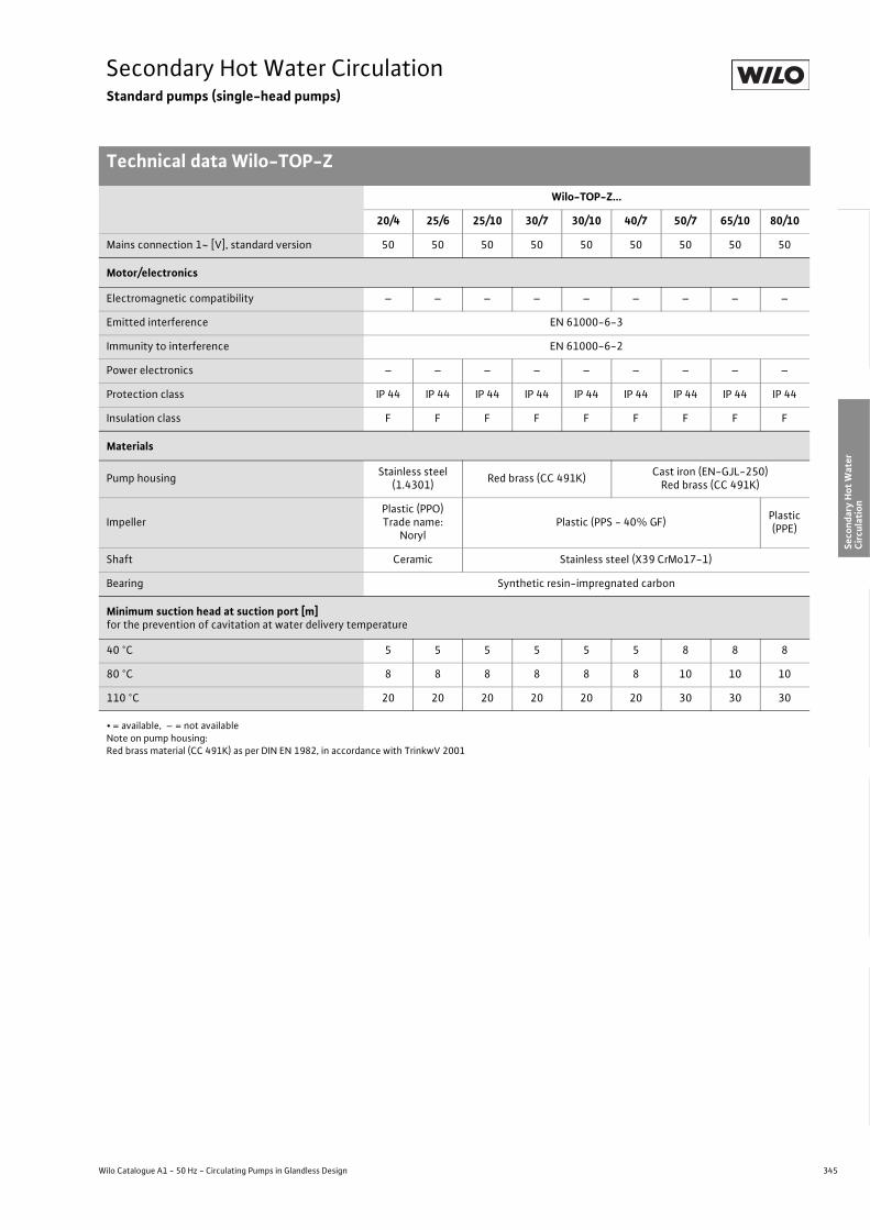
345
Secondary Hot Water CirculationStandard pumps (single-head pumps)
Technical data Wilo-TOP-Z
Wilo Catalogue A1 - 50 Hz - Circulating Pumps in Glandless Design
Hea
ting,
Air-
cond
ition
ing,
Co
olin
gSe
cond
ary
Hot W
ater
Circ
ulat
ion
Sola
r The
rmal
, Geo
ther
mal
En
ergy
Sys
tem
sSe
rvic
e/Ac
cess
orie
s, S
yste
ms
Switc
hgea
rs a
nd C
ontr
ol
Dev
ices
Pum
p M
anag
emen
t Sys
tem
s
Mains connection 1~ [V], standard version 50 50 50 50 50 50 50 50 50
Motor/electronics
Electromagnetic compatibility – – – – – – – – –
Emitted interference EN 61000-6-3
Immunity to interference EN 61000-6-2
Power electronics – – – – – – – – –
Protection class IP 44 IP 44 IP 44 IP 44 IP 44 IP 44 IP 44 IP 44 IP 44
Insulation class F F F F F F F F F
Materials
Pump housing Stainless steel (1.4301) Red brass (CC 491K) Cast iron (EN-GJL-250)
Red brass (CC 491K)
ImpellerPlastic (PPO)Trade name:
NorylPlastic (PPS - 40% GF) Plastic
(PPE)
Shaft Ceramic Stainless steel (X39 CrMo17-1)
Bearing Synthetic resin-impregnated carbon
Minimum suction head at suction port [m]for the prevention of cavitation at water delivery temperature
40 °C 5 5 5 5 5 5 8 8 8
80 °C 8 8 8 8 8 8 10 10 10
110 °C 20 20 20 20 20 20 30 30 30
Wilo-TOP-Z...
20/4 25/6 25/10 30/7 30/10 40/7 50/7 65/10 80/10
• = available, – = not availableNote on pump housing:Red brass material (CC 491K) as per DIN EN 1982, in accordance with TrinkwV 2001

346 Subject to change without prior notice 09/2007 WILO AG
Secondary Hot Water CirculationStandard pumps (single-head pumps)
Pump curves Wilo-TOP-Z
Wilo-TOP-Z 20/4
AC Three-phase (DM)
Wilo-TOP-Z 25/6
AC Three-phase (DM)
Pump curves Wilo-TOP-Z
0 1 2 3 4
0 1 2 3 4 [m 3/h]
P1 [
W]
H [m
]
Q
[m 3/h]
110
100
90
80
70
60
50
40
30
4
3
2
1
0
0 0,25 0,5 0,75 1 1,25
0 2,5 5 7,5 10 12,5 15 [lgpm]
[l/s]
min.
v[m/s]
max.
max.
min.
v
Wilo-TOP-Z 20/41~230 V - Rp ¾
0,50 1,0 1,5 2,0 2,5 3,0 3,5 4,0
0 0,25 0,5 0,75 1 1,25
[lgpm]
[l/s]0 1 2 3 4
0 1 2 3 4 [m 3/h]
P1 [
W]
H [m
]
[m 3/h]
110
100
90
80
70
60
50
40
30
4
3
2
1
0
max.
min.
max.
min.
0 2,5 5 7,5 10 12,5 15
v[m/s]
Wilo-TOP-Z 20/43~400 V - Rp ¾
0,50 1,0 1,5 2,0 2,5 3,0 3,5 4,0
Q
0 0,25 0,5 0,75 1 1,25 1,5
0 2,5 5 7,5 10 12,5 15 17,5
0 1 2 3 4 5
0 1 2 3 4 5 [m 3/h]
P1 [
W]
H [m
]
Q
[m 3/h]
[lgpm]
220
200
180
160
140
120
100
80
60
7
6
5
4
3
2
1
0
[l/s]
max.
min.
0 0,5 1 1,5 2 2,5 3v
[m/s]
min.
max.
Wilo-TOP-Z 25/61~230 V - Rp 1
0 0,5 1 1,5 2 2,5 3v
[m/s]
0 0,25 0,5 0,75 1 1,25 1,5
0 2,5 5 7,5 10 12,5 15 17,5
0 1 2 3 4 5
0 1 2 3 4 5 [m 3/h]
P1 [
W]
H [m
]
Q
[m 3/h]
[lgpm]
220
200
180
160
140
120
100
80
60
7
6
5
4
3
2
1
0
[l/s]
max.
min.
min.
max.
Wilo-TOP-Z 25/63~400 V - Rp 1

347
Secondary Hot Water CirculationStandard pumps (single-head pumps)
Pump curves Wilo-TOP-Z
Wilo Catalogue A1 - 50 Hz - Circulating Pumps in Glandless Design
Hea
ting,
Air-
cond
ition
ing,
Co
olin
gSe
cond
ary
Hot W
ater
Circ
ulat
ion
Sola
r The
rmal
, Geo
ther
mal
En
ergy
Sys
tem
sSe
rvic
e/Ac
cess
orie
s, S
yste
ms
Switc
hgea
rs a
nd C
ontr
ol
Dev
ices
Pum
p M
anag
emen
t Sys
tem
s
Wilo-TOP-Z 25/10
AC Three-phase (DM)
Wilo-TOP-Z 30/7
AC Three-phase (DM)
0 0,5 1 1,5 2 2,5
0 5 10 15 20 25 30
0 1 2 3 4 5 6 7 8 9
0 1 2 3 4 5 6 7 8 9 [m 3/h]
P1 [
W]
H[m
]
Q
[m 3/h]
[lgpm]
[l/s]
max.
min.
0 0,5 1 1,5 2 2,5 3v
[m/s]
0
1
2
3
4
5
0
50
100
150
200
250
300
350
6
7
8
9
10
max.
min.
Wilo-TOP-Z 25/101~230V - Rp 1
0 0,5 1 1,5 2 2,5
0 5 10 15 20 25 30
0 1 2 3 4 5 6 7 8 9
0 1 2 3 4 5 6 7 8 9 [m 3/h]
P1 [
W]
H[m
]
Q
[m 3/h]
[lgpm]
[l/s]
max. (1 )
min. (3 )
(2 )
0 0,5 1 1,5 2 2,5 3v
[m/s]
0
1
2
3
4
5
0
50
100
150
200
250
300
350
6
7
8
9
10
max.
min.
Wilo-TOP-Z 25/103~400V - Rp 1
200
175
150
125
100
75
50
0 0,5 1 1,5 2
0 5 10 15 20 25
0 0,5 1 1,5 2 2,5
0 1 2 3 4 5 6 7
v [m/s]
P1 [
W]
H [m
]
Q
[m3/h]
[lgpm]
6
5
4
3
2
1
0
[l/s]
[m3/h]
min.
0 1 2 3 4 5 6 7
max.
min.
Wilo-TOP-Z 30/71~230 V - Rp 1¼
max.
160
140
120
100
80
60
40
20
0
P1 [
W]
H [m
]
Q
[m3/h]
6
5
4
3
2
1
0
max.
min.
0 0,5 1 1,5 2
0 5 10 15 20 25
0 0,5 1 1,5 2 2,5
0 1 2 3 4 5 6 7
v [m/s]
[lgpm]
[l/s]
[m3/h]0 1 2 3 4 5 6 7
Wilo-TOP-Z 30/73~400 V - Rp 1¼
max.
min.
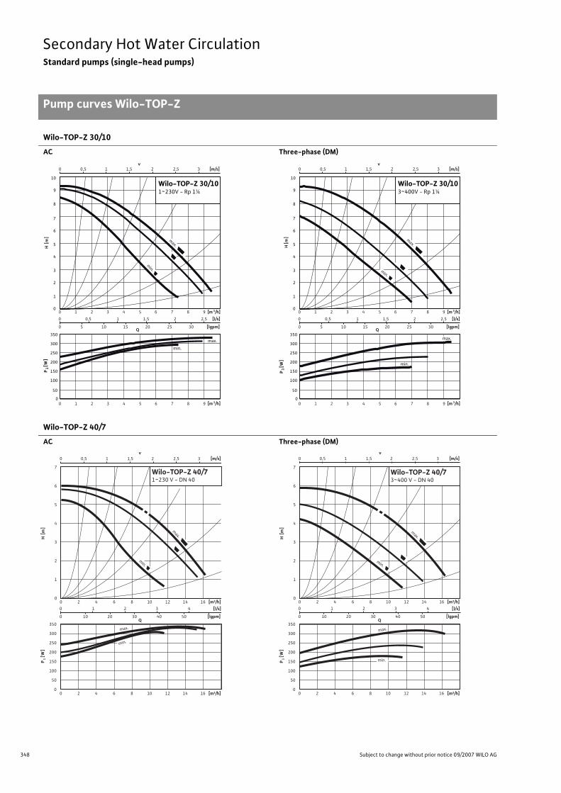
348 Subject to change without prior notice 09/2007 WILO AG
Secondary Hot Water CirculationStandard pumps (single-head pumps)
Pump curves Wilo-TOP-Z
Wilo-TOP-Z 30/10
AC Three-phase (DM)
Wilo-TOP-Z 40/7
AC Three-phase (DM)
0 0,5 1 1,5 2 2,5
0 5 10 15 20 25 30
0 1 2 3 4 5 6 7 8 9
0 1 2 3 4 5 6 7 8 9 [m 3/h]
P1 [
W]
H[m
]
Q
[m 3/h]
[lgpm]
[l/s]
max.
min.
0 0,5 1 1,5 2 2,5 3v
[m/s]
0
1
2
3
4
5
0
50
100
150
200
250
300
350
6
7
8
9
10
max.
min.
Wilo-TOP-Z 30/101~230V - Rp 1¼
0 0,5 1 1,5 2 2,5
0 5 10 15 20 25 30
0 1 2 3 4 5 6 7 8 9
0 1 2 3 4 5 6 7 8 9 [m 3/h]
P1 [
W]
H[m
]
Q
[m 3/h]
[lgpm]
[l/s]
max.
min.
0 0,5 1 1,5 2 2,5 3v
[m/s]
0
1
2
3
4
5
0
50
100
150
200
250
300
350
6
7
8
9
10
max.
min.
Wilo-TOP-Z 30/103~400V - Rp 1¼
0 1 2 3 4
0 10 20 30 40 50
0 0,5 1 1,5 2 2,5 3
0 2 4 6 8 10 12 14 16
v [m/s]
P1 [
W]
H [m
]
Q
[m3/h]
[lgpm]
7
6
5
4
3
2
1
0
[l/s]
[m3/h]
max.350
300
250
200
150
100
50
0
min.
min.
0 2 4 6 8 10 12 14 16
max.
Wilo-TOP-Z 40/71~230 V - DN 40
350
300
250
200
150
100
50
0
P1 [
W]
H [m
]
Q
7
6
5
4
3
2
1
0
[m3/h]
max.
min.
0 1 2 3 4
0 10 20 30 40 50
0 0,5 1 1,5 2 2,5 3
0 2 4 6 8 10 12 14 16
v [m/s]
[m3/h]
[lgpm]
[l/s]
0 2 4 6 8 10 12 14 16
min.
max.
Wilo-TOP-Z 40/73~400 V - DN 40

349
Secondary Hot Water CirculationStandard pumps (single-head pumps)
Pump curves Wilo-TOP-Z
Wilo Catalogue A1 - 50 Hz - Circulating Pumps in Glandless Design
Hea
ting,
Air-
cond
ition
ing,
Co
olin
gSe
cond
ary
Hot W
ater
Circ
ulat
ion
Sola
r The
rmal
, Geo
ther
mal
En
ergy
Sys
tem
sSe
rvic
e/Ac
cess
orie
s, S
yste
ms
Switc
hgea
rs a
nd C
ontr
ol
Dev
ices
Pum
p M
anag
emen
t Sys
tem
s
Wilo-TOP-Z 50/7 Wilo-TOP-Z 65/10
Three-phase (DM) Three-phase (DM)
Wilo-TOP-Z 80/10
Three-phase (DM)
800
600
400
200
0
0 1 2 3 4 5 6 7
0 25 50 75
0 0,5 1 1,5 2 2,5 3 3,5
0 5 10 15 20 25
0 5 10 15 20 25
v [m/s]
P1 [
W]
H [m
]
Q
[m3/h]
[lgpm]
8
7
6
5
4
3
2
1
0
[l/s]
[m3/h]
max.
min.
max.
min.
Wilo-TOP-Z 50/73~400 V - DN 50
1200
1100
1000
900
800
700
600
500
400
0 1 2 3 4 5 6 7 8 9 10 11
0 20 40 60 80 100 120 140
0 0,5 1 1,5 2 2,5
0 5 10 15 20 25 30 35 40
0 5 10 15 20 25 30 35 40
v [m/s]
P1 [
W]
H [m
]
Q
[m3/h]
[lgpm]
9
8
7
6
5
4
3
2
1
0
[l/s]
[m3/h]
max.
min.
min.
max.
Wilo-TOP-Z 65/103~400 V - DN 65
1500
1400
1300
1200
1100
1000
900
800
0 2 4 6 8 10 12 14 16 18
0 50 100 150 200
0 0,5 1 1,5 2 2,5 3
0 10 20 30 40 50 60
0 10 20 30 40 50 60
v [m/s]
P1 [
W]
H [m
]
Q
[m3/h]
[lgpm]
9
8
7
6
5
4
3
2
1
0
[l/s]
[m3/h]
max.
min.
min.
max.
Wilo-TOP-Z 80/103~400 V - DN 80
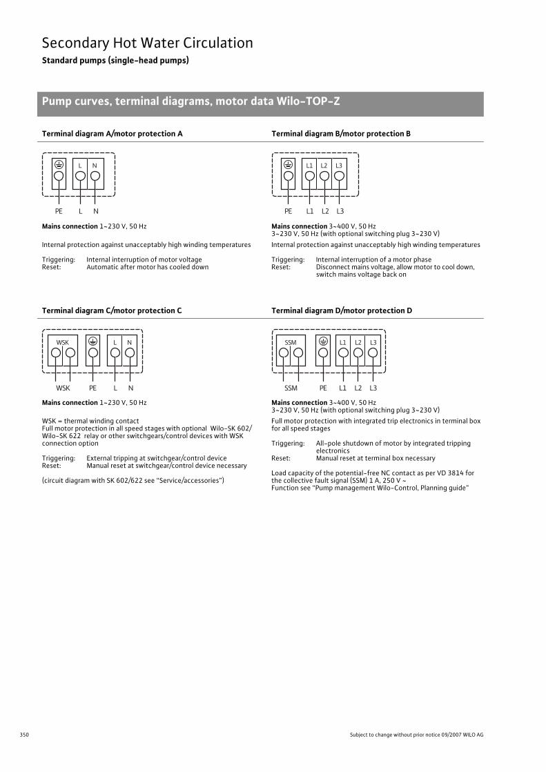
350 Subject to change without prior notice 09/2007 WILO AG
Secondary Hot Water CirculationStandard pumps (single-head pumps)
Pump curves, terminal diagrams, motor data Wilo-TOP-Z
Terminal diagram A/motor protection A Terminal diagram B/motor protection B
Mains connection 1~230 V, 50 Hz Mains connection 3~400 V, 50 Hz3~230 V, 50 Hz (with optional switching plug 3~230 V)
Internal protection against unacceptably high winding temperatures
Triggering: Internal interruption of motor voltageReset: Automatic after motor has cooled down
Internal protection against unacceptably high winding temperatures
Triggering: Internal interruption of a motor phaseReset: Disconnect mains voltage, allow motor to cool down,
switch mains voltage back on
Terminal diagram C/motor protection C Terminal diagram D/motor protection D
Mains connection 1~230 V, 50 Hz Mains connection 3~400 V, 50 Hz3~230 V, 50 Hz (with optional switching plug 3~230 V)
WSK = thermal winding contactFull motor protection in all speed stages with optional Wilo-SK 602/ Wilo-SK 622 relay or other switchgears/control devices with WSK connection option
Triggering: External tripping at switchgear/control deviceReset: Manual reset at switchgear/control device necessary
(circuit diagram with SK 602/622 see “Service/accessories”)
Full motor protection with integrated trip electronics in terminal box for all speed stages
Triggering: All-pole shutdown of motor by integrated tripping electronics
Reset: Manual reset at terminal box necessary
Load capacity of the potential-free NC contact as per VD 3814 for the collective fault signal (SSM) 1 A, 250 V ~Function see “Pump management Wilo-Control, Planning guide”
Pump curves, terminal diagrams, motor data Wilo-TOP-Z
L NPE
NL
L1 L2PE
L2
L3
L3L1
L NPE
NL
WSK
WSK
L1 L2 L3PE
L1 L2 L3
SSM
SSM

351
Secondary Hot Water CirculationStandard pumps (single-head pumps)
Pump curves, terminal diagrams, motor data Wilo-TOP-Z
Wilo Catalogue A1 - 50 Hz - Circulating Pumps in Glandless Design
Hea
ting,
Air-
cond
ition
ing,
Co
olin
gSe
cond
ary
Hot W
ater
Circ
ulat
ion
Sola
r The
rmal
, Geo
ther
mal
En
ergy
Sys
tem
sSe
rvic
e/Ac
cess
orie
s, S
yste
ms
Switc
hgea
rs a
nd C
ontr
ol
Dev
ices
Pum
p M
anag
emen
t Sys
tem
s
Motor data
Wilo-TOP-Z... Nominalpower Stage/speed Power
consumptionCurrent at Capaci-
torThreaded
cableconnection
Motorprotection
Terminaldiagram
1~230 V 3~400 V 3~230 V
P2 n P1 I – PG – –[W] [1/min] [W] [A] [�F/VDB] – – –
20/4(1-phase motor) 60
max. 2790 2600
min. 2100
95 - 10570 - 8050 - 65
0.500.400.35
– – 3.5/400 1 x 13.5 A A
20/4(3-phase motor) 60
max. 2850 2650
min. 2440
80 - 10045 - 6535 - 50
–0.350.150.10
0.600.300.20
– 1 x 13.5 B B
25/6(1-phase motor) 100
max. 2390 1810
min. 1260
140 - 200115 - 175 85 - 120
1.000.900.65
– – 5/400 1 x 13.5 A A
25/6(3-phase motor) 100
max. 2450 1880
min. 1590
125 - 210 80 - 135
60 - 95–
0.450.250.20
0.800.450.35
– 1 x 13.5 B B
25/10(1-phase motor) 180
max. 2800 2500
min. 2400
210 - 325170 - 315150 - 295
1.621.581.51
– – 8/400 2 x 13.5 C C
25/10(3-phase motor) 180
max. 2700 2400
min. 2000
175 - 310125 - 230100 - 175
–0.770.430.32
1.330.740.55
– 2 x 13.5 D D
30/7(1-phase motor) 90
max. 2700 2500
min. 2100
135 - 165100 - 145 70 - 110
0.800.720.56
– – 5/400 1 x 13.5 A A
30/7(3-phase motor) 90
max. 2700 2350
min. 2050
105 - 155 70 - 105
50 - 80–
0.420.210.15
0.720.370.26
– 1 x 13.5 B B
30/10(1-phase motor) 180
max. 28002600
min. 2400
210 - 335170 - 315150 - 295
1.621.581.51
– – 8/400 2 x 13.5 C C
30/10(3-phase motor) 180
max. 27002400
min. 2000
175 - 310125 - 230100 - 175
–0.770.430.32
1.330.740.55
– 2 x 13.5 D D
40/7(1-phase motor) 180
max. 2700 2600
min. 2400
240 - 340200 - 330175 - 310
1.621.601.54
– – 8/400 2 x 13.5 C C
40/7(3-phase motor) 180
max. 2700 2300
min. 2000
195 - 320145 - 240120 - 180
–0.700.440.32
1.220.760.55
– 2 x 13.5 D D
50/7(3-phase motor) 350
max. 2700 2300
min. 2000
375 - 680280 - 520240 - 390
–1.380.920.69
2.381.601.19
– 2 x 13.5 D D
65/10(3-phase motor) 700
max. 2850 2700
min. 2500
760 - 1050580 - 840515 - 720
–2.421.551.30
4.192.682.25
– 2 x 13.5 D D
80/10(3-phase motor) 1100
max. 2800 2500
min. 2200
1290 - 14401055 - 1155
865 - 940–
2.922.061.68
5.063.562.91
– 2 x 13.5 D D
Always refer to name plate data! Current I: Onsite thermal overload settings.
Note:3~230 V only with optional switching plug (accessories)
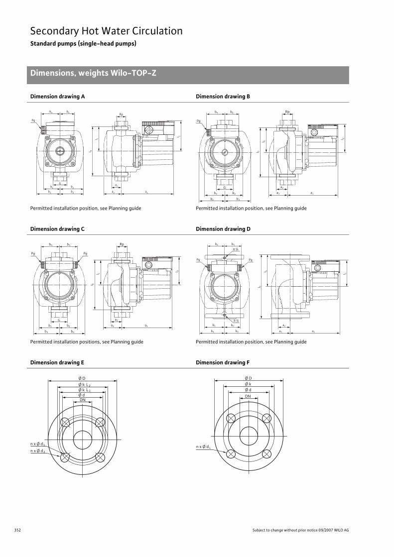
352 Subject to change without prior notice 09/2007 WILO AG
Secondary Hot Water CirculationStandard pumps (single-head pumps)
Dimensions, weights Wilo-TOP-Z
Dimension drawing A Dimension drawing B
Permitted installation position, see Planning guide Permitted installation position, see Planning guide
Dimension drawing C Dimension drawing D
Permitted installation positions, see Planning guide Permitted installation position, see Planning guide
Dimension drawing E Dimension drawing F
Dimen-sions, weights Wilo-TOP-Z
l 0
Pg
b3 b3 a3 a1
b1
l 2
G a2b2
b4 b5
l 1
Rp
Pg
Rp
b1 b2
b3 b3
G
l 0
l 2
a3
a2
a1
l 1
b4 b5
Pg Pg
Rp
b1 b2
b3 b3
G
l 0
l 2
a3
a2
a1
l 1
b4 b5
PgPgl 0
l 2
b1 b2
b3 b3
R 1/8
R 1 / 8
a2
a1a3
b4 b5
l 1
Ø D
n x Ø d
Ø k
DN
L2Ø k Ø d
L 1
1
n x Ø d 2n x Ø d
Ø D Ø k
DN
Ø d
L

353
Secondary Hot Water CirculationStandard pumps (single-head pumps)
Dimensions, weights Wilo-TOP-Z
Wilo Catalogue A1 - 50 Hz - Circulating Pumps in Glandless Design
Hea
ting,
Air-
cond
ition
ing,
Co
olin
gSe
cond
ary
Hot W
ater
Circ
ulat
ion
Sola
r The
rmal
, Geo
ther
mal
En
ergy
Sys
tem
sSe
rvic
e/Ac
cess
orie
s, S
yste
ms
Switc
hgea
rs a
nd C
ontr
ol
Dev
ices
Pum
p M
anag
emen
t Sys
tem
s
Dimensions, weights
Wilo-TOP-Z... Pipeconnection/
nominal diameter
Thread Pump dimensions Weightabout
Dimensiondrawing
[Rp/DN] G I0 l1 l2 a1 a2 a3 b1 b2 b3 b4 b5 PN 6/10 –– – [mm] [kg] –
20/4 Rp 3/4 G 11/4 150 75 92 162 30 54 50 50 70 60 44 3.1 A
25/6 Rp 1 G 11/2 180 90 92 162 30 54 50 50 70 60 44 3.3 A
25/10 Rp 1 G 11/2 180 90 102 172 52 73 69 68 92 66 66 6.7 C
30/7 Rp 11/4 G 2 180 90 92 172 34 64 66 57 88 60 44 5.5 B
30/10 Rp 11/4 G 2 180 90 102 172 52 73 69 61 92 66 66 6.7 C
40/7 DN 40 – 250 125 102 193 46 72 78 62 97 66 66 13.0 D
50/7 DN 50 – 280 140 109 224 65 82 91 77 119 66 66 19.5 D
65/10 DN 65 – 340 170 119 253 80 100 118 98 136 66 66 29.5 D
80/10 DN 80 – 360 180 119 258 95 130 135 108 159 66 66 32.5/35 D
Flange dimensions
Wilo-TOP-Z... Flange Nominaldiameter
Pump flange dimensions Dimensiondrawing
– DN Ø D Ø d Ø kL1/kL2 Ø k n x Ø dL1/dL2 n x Ø dL –– – [mm] [pcs. x mm] [pcs. x mm] –
40/7 Combination flange PN 6/10(flange PN 16, as per DIN 2533) 40 150 88 100/110 – 4 x 14 / 19 – E
50/7 Combination flange PN 6/10(flange PN 16, as per DIN 2533) 50 165 102 110/125 – 4 x 14 / 19 - E
65/10 Combination flange PN 6/10(flange PN 16, as per DIN 2533) 65 185 122 130/145 – 4 x 14 / 19 - E
80/10
Flange PN 6(designed to PN 16, as per DIN 2531)
80 190 128 – 150 - 4 x 19 F
Flange PN 16 (as per DIN 2533, drilled as per EN 1092-2)
80 200 138 – 160 - 8 x 19 F
n = No. of bolt holes
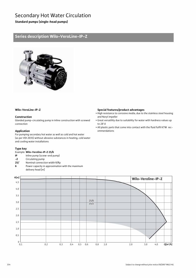
354 Subject to change without prior notice 09/2007 WILO AG
Secondary Hot Water CirculationStandard pumps (single-head pumps)
Series description Wilo-VeroLine-IP-Z
Wilo-VeroLine-IP-Z
ConstructionGlanded pump-circulating pump in Inline construction with screwed connection
ApplicationFor pumping secondary hot water as well as cold and hot water (as per VDI 2035) without abrasive substances in heating, cold water and cooling water installations
Type keyExample: Wilo-Veroline-IP-Z 25/6IP Inline pump (screw-end pump)-Z Circulating pump25/ Nominal connection width R/Rp6 Power capacity in approximation with the maximum
delivery head [m]
Special features/product advantages• High resistance to corrosive media, due to the stainless steel housing
and Noryl impeller• Great versatility due to suitability for water with hardness values up
to 28°d• All plastic parts that come into contact with the fluid fulfil KTW rec-
ommendations
Wilo-Veroline-IP-Z
Q[m³/h]0,1 0,2 0,3 0,4 0,5 0,6 0,8 1,0 2,0 3,0 4,0
H[m]
0
0,5
1,0
1,5
2,0
2,5
3,0
3,5
4,0
4,5
25/625/2
355
Secondary Hot Water CirculationStandard pumps (single-head pumps)
Series description Wilo-VeroLine-IP-Z
Wilo Catalogue A1 - 50 Hz - Circulating Pumps in Glandless Design
Hea
ting,
Air-
cond
ition
ing,
Co
olin
gSe
cond
ary
Hot W
ater
Circ
ulat
ion
Sola
r The
rmal
, Geo
ther
mal
En
ergy
Sys
tem
sSe
rvic
e/Ac
cess
orie
s, S
yste
ms
Switc
hgea
rs a
nd C
ontr
ol
Dev
ices
Pum
p M
anag
emen
t Sys
tem
s
Equipment/function
Manual functions• Setting the speed stages: 1 speed stage
Equipment/scope of delivery• Including installation and operating instructions
Accessories• Adapters• Motor protection switch

356 Subject to change without prior notice 09/2007 WILO AG
Secondary Hot Water CirculationStandard pumps (single-head pumps)
Technical data Wilo-VeroLine-IP-Z
Wilo-VeroLine-IP-Z
Approved fluids(other fluids on request)
Heating water (as per VDI 2035) •Water-glycol mixture(for 20-40 vol.-% glycol and fluid temperature � 40 °C) •
Cooling and cold water •
Hot water –
Heat transfer oil –
Secondary hot water and water for food businesses as per TrinkwV 2001 •
Permitted field of application
Nominal pressure, maximum [bar] 10
Temperature range [°C] -8 to +110
Ambient temperature, maximum [°C] 40
Installation in closed buildings •Outdoor installation Special version at additional charge
Pipe connections
Threaded connection G 1 1/2
Flange connection(groove and tongue-faced flange, DIN DIN 2445) –
Flange version PN 10
Nominal connection widths DN –
Flange with pressure-measurement connections –
Materials
Pump housing and lantern 1.4306
Impeller Noryl
Shaft 1.4571
Mechanical seal Ceramic/graphite/EPDM
Other mechanical seals –
Electrical connections (other versions on request)
Mains connection 3~ [V/Hz] 400/50
Mains connection 1~ [V/Hz] 230/50
Speed, maximum [1/min] 1450/2900
• = available, – = not available
Technical data Wilo-VeroLine-IP-Z

357
Secondary Hot Water CirculationStandard pumps (single-head pumps)
Technical data Wilo-VeroLine-IP-Z
Wilo Catalogue A1 - 50 Hz - Circulating Pumps in Glandless Design
Hea
ting,
Air-
cond
ition
ing,
Co
olin
gSe
cond
ary
Hot W
ater
Circ
ulat
ion
Sola
r The
rmal
, Geo
ther
mal
En
ergy
Sys
tem
sSe
rvic
e/Ac
cess
orie
s, S
yste
ms
Switc
hgea
rs a
nd C
ontr
ol
Dev
ices
Pum
p M
anag
emen
t Sys
tem
s
Motor/electronics
Integrated full motor protection(see accessories for necessary relay)
–
Protection class IP 44 (motor)IP 54 (terminal box)
Insulation class F
Motor protection required onsite •Speed control –
Motor winding up to 3 kW 3~230 V �/400 V Y, 50 Hz
Motor winding starting at 4 kW –
Installation options
Pipe mounting (up to 15 kW motor power) •Support-bracket mounting –
• = available, – = not available
Wilo-VeroLine-IP-Z
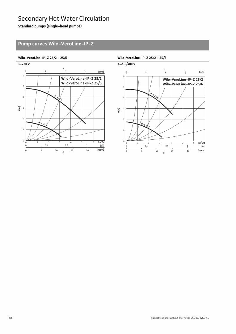
358 Subject to change without prior notice 09/2007 WILO AG
Secondary Hot Water CirculationStandard pumps (single-head pumps)
Pump curves Wilo-VeroLine-IP-Z
Wilo-VeroLine-IP-Z 25/2 - 25/6
1~230 V
Wilo-VeroLine-IP-Z 25/2 - 25/6
3~230/400 VPump curves Wilo-VeroLine-IP-Z
0 1 2 3 v
Q [lgpm]
[l/s]
0
0 0
0,5 1 2 3 4 5 6
5 10 15 20
0,5 1
0
2
1
3
4
5
6
H[m
]
[m/h]
[m3/h]
Wilo-VeroLine-IP-Z 25/2Wilo-VeroLine-IP-Z 25/6
IP-Z 25/2
IP-Z 25/6
0 1 2 3 v
[m/s]
[m3/h]
Q [lgpm]
[l/s]
0
0 0
0,5 1 2 3 4 5 6
5 10 15 20
0,5 1
0
2
1
3
4
5
6
H[m
]
Wilo-VeroLine-IP-Z 25/2 Wilo-VeroLine-IP-Z 25/6
IP-Z 25/2
IP-Z 25/6
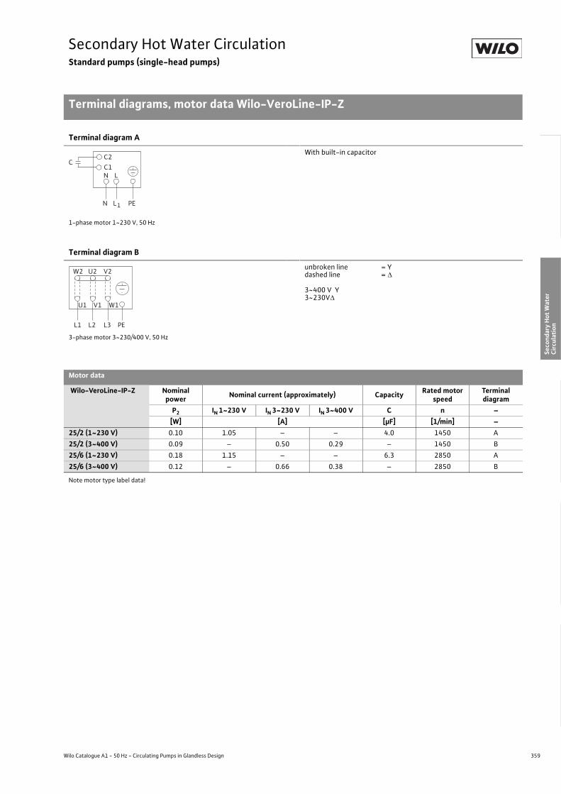
359
Secondary Hot Water CirculationStandard pumps (single-head pumps)
Terminal diagrams, motor data Wilo-VeroLine-IP-Z
Wilo Catalogue A1 - 50 Hz - Circulating Pumps in Glandless Design
Hea
ting,
Air-
cond
ition
ing,
Co
olin
gSe
cond
ary
Hot W
ater
Circ
ulat
ion
Sola
r The
rmal
, Geo
ther
mal
En
ergy
Sys
tem
sSe
rvic
e/Ac
cess
orie
s, S
yste
ms
Switc
hgea
rs a
nd C
ontr
ol
Dev
ices
Pum
p M
anag
emen
t Sys
tem
s
Terminal diagram A
1-phase motor 1~230 V, 50 Hz
With built-in capacitor
Terminal diagram B
3-phase motor 3~230/400 V, 50 Hz
unbroken line = Ydashed line = �
3~400 V Y3~230V�
Motor data
Wilo-VeroLine-IP-Z Nominal power Nominal current (approximately) Capacity Rated motor
speedTerminal diagram
P2 IN 1~230 V IN 3~230 V IN 3~400 V C n –[W] [A] [�F] [1/min] –
25/2 (1~230 V) 0.10 1.05 – – 4.0 1450 A25/2 (3~400 V) 0.09 – 0.50 0.29 – 1450 B25/6 (1~230 V) 0.18 1.15 – – 6.3 2850 A25/6 (3~400 V) 0.12 – 0.66 0.38 – 2850 B
Note motor type label data!
Terminal diagrams, motor data Wilo-VeroLine-IP-Z
L
L1
N
N PE
C1C2
C
L1 L2 L3 PE
W2 U2 V2
U1 V1 W1

360 Subject to change without prior notice 09/2007 WILO AG
Secondary Hot Water CirculationStandard pumps (single-head pumps)
Dimensions, weights Wilo-VeroLine-IP-Z
Dimension drawing
Dimensions, weights
Wilo-VeroLine-IP-Z Nominaldiameter
Dimensions Weightabout
DN l0 l1 a a1 a2 b c e f Ø g –– [mm] [kg]
25/2 (1~230 V) 25 180 250 241 213 136 148 92 58 82 115 5.525/2 (3~400 V) 25 180 250 241 213 136 148 92 58 – 115 4.525/6 (1~230 V) 25 180 250 241 213 136 148 92 58 82 115 5.525/6 (3~400 V) 25 180 250 241 213 136 148 92 58 – 115 4.5
Dimen-sions, weights Wilo-VeroLine-IP-Z
a
G1½
f
1~230 V
e e
3~230/400 V
e
Øg
c
b
G½
" x G
2
a1
a2
l0l1

361
Solar Thermal, Geothermal Energy SystemsContents
Wilo Catalogue A1 - 50 Hz - Circulating Pumps in Glandless Design
Hea
ting,
Air-
cond
ition
ing,
Co
olin
gSe
cond
ary
Hot W
ater
Circ
ulat
ion
Sola
r The
rmal
, Geo
ther
mal
En
ergy
Sys
tem
sSe
rvic
e/Ac
cess
orie
s, S
yste
ms
Switc
hgea
rs a
nd C
ontr
ol
Dev
ices
Pum
p M
anag
emen
t Sys
tem
s
Solar thermal, geothermal energy systems
High-efficiency pumps Wilo-Stratos ECO-ST 362
Series overview 362
Wilo-Stratos ECO-ST 362
Equipment/function 364
Series description 366
Technical data 368
Pump curves 370
Terminal diagram, motor data 371
Dimensions, weights 372
Standard pumps Wilo-Star-ST, Star-RSG 374
Series overview 374
Wilo-Star-ST 374
Equipment/function 376
Series description 378
Technical data 380
Pump curves 382
Terminal diagrams, motor data 384
Dimensions, weights 385
Wilo-Star-RSG 374
Equipment/function 376
Series description 386
Technical data 388
Pump curves 390
Terminal diagrams, motor data 391
Dimensions, weights 392

362 Subject to change without prior notice 09/2007 WILO AG
Solar Thermal, Geothermal Energy SystemsHigh-efficiency pumps (single-head pumps)
Series overview Wilo-Stratos ECO-ST
Series: Wilo-Stratos ECO-ST
>Single-head pumps:• Glandless circulating pumps with screwed
connection>Application:• High-flow volume and low-flow volume
solar thermal systems
0
1
2
3
4
0 0,5 1,0 1,5 2,0 Q[m³/h]
H [m
]
Wilo-Stratos ECO-ST
15(25)1-5

363
Solar Thermal, Geothermal Energy SystemsHigh-efficiency pumps (single-head pumps)
Series overview Wilo-Stratos ECO-ST
Wilo Catalogue A1 - 50 Hz - Circulating Pumps in Glandless Design
Hea
ting,
Air-
cond
ition
ing,
Co
olin
gSe
cond
ary
Hot W
ater
Circ
ulat
ion
Sola
r The
rmal
, Geo
ther
mal
En
ergy
Sys
tem
sSe
rvic
e/Ac
cess
orie
s, S
yste
ms
Switc
hgea
rs a
nd C
ontr
ol
Dev
ices
Pum
p M
anag
emen
t Sys
tem
s
Series: Wilo-Stratos ECO-ST
> Product advantages:• Class A motor technology• Up to 80 % energy savings in comparison to uncontrolled circulating pumps• Highest degrees of efficiency due to ECM technology• Minimum electronic power consumption: only 5.8 Watt• 3- times greater starting torque than conventional circulating pumps• Pump housing with wrench attachment point• Pump housing with cataphoretic (KTL) coating for the prevention of corrosion from condensa-
tion formation• BA linkup: For linkage to external monitoring units (e.g. building automation BA or DDC instal-
lations)
> Additional information: Page• Planning guide: . . . . . . . . . . . . . . . . . . 6/29• Equipment/function: . . . . . . . . . . . . . 364• Series description: . . . . . . . . . . . . . . . . 366• Technical data: . . . . . . . . . . . . . . . . . . . 368• Pump curves: . . . . . . . . . . . . . . . . . . . . 370• Terminal diagrams, motor data: . . . . 371• Dimensions, weights: . . . . . . . . . . . . . 372• Service/accessories: . . . . . . . . . . . . . . 393
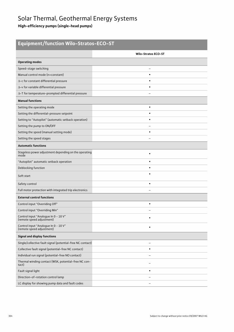
364 Subject to change without prior notice 09/2007 WILO AG
Solar Thermal, Geothermal Energy SystemsHigh-efficiency pumps (single-head pumps)
Equipment/function Wilo-Stratos-ECO-ST
Wilo-Stratos ECO-ST
Operating modes
Speed-stage switching –
Manual control mode (n=constant) •�-c for constant differential pressure •�-v for variable differential pressure •�-T for temperature-prompted differential pressure –
Manual functions
Setting the operating mode •Setting the differential-pressure setpoint •Setting to “Autopilot” (automatic setback operation) •Setting the pump to ON/OFF –
Setting the speed (manual setting mode) •Setting the speed stages –
Automatic functions
Stageless power adjustment depending on the operating mode •
“Autopilot” automatic setback operation •Deblocking function •
Soft start •
Safety control •Full motor protection with integrated trip electronics –
External control functions
Control input “Overriding Off” •Control input “Overriding Min” –
Control input “Analogue In 0 - 10 V” (remote speed adjustment) •
Control input “Analogue In 0 - 10 V” (remote speed adjustment) •
Signal and display functions
Single/collective fault signal (potential-free NC contact) –
Collective fault signal (potential-free NC contact) •Individual run signal (potential-free NO contact) –
Thermal winding contact (WSK, potential-free NC con-tact) –
Fault signal light •Direction-of-rotation control lamp –
LC display for showing pump data and fault codes –
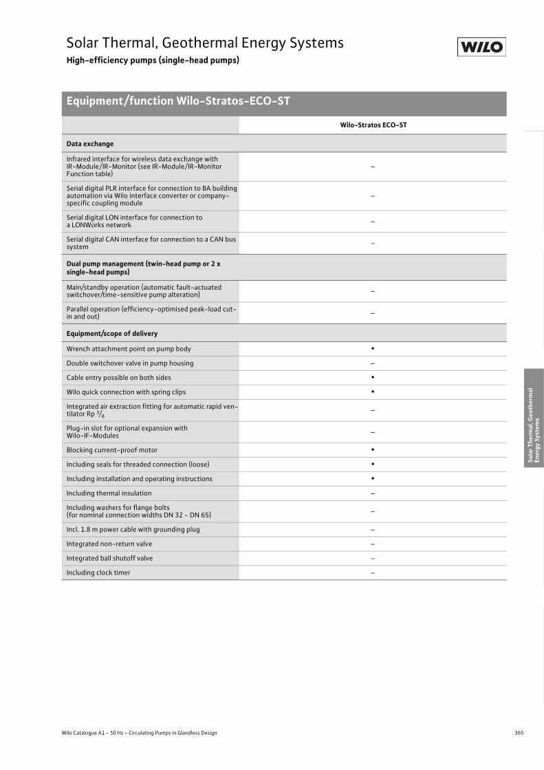
365
Solar Thermal, Geothermal Energy SystemsHigh-efficiency pumps (single-head pumps)
Equipment/function Wilo-Stratos-ECO-ST
Wilo Catalogue A1 - 50 Hz - Circulating Pumps in Glandless Design
Hea
ting,
Air-
cond
ition
ing,
Co
olin
gSe
cond
ary
Hot W
ater
Circ
ulat
ion
Sola
r The
rmal
, Geo
ther
mal
En
ergy
Sys
tem
sSe
rvic
e/Ac
cess
orie
s, S
yste
ms
Switc
hgea
rs a
nd C
ontr
ol
Dev
ices
Pum
p M
anag
emen
t Sys
tem
s
Data exchange
Infrared interface for wireless data exchange with IR-Module/ IR-Monitor (see IR-Module/ IR-Monitor Function table)
–
Serial digital PLR interface for connection to BA building automation via Wilo interface converter or company-specific coupling module
–
Serial digital LON interface for connection to a LONWorks network –
Serial digital CAN interface for connection to a CAN bus system –
Dual pump management (twin-head pump or 2 x single-head pumps)
Main/standby operation (automatic fault-actuated switchover/time-sensitive pump alteration) –
Parallel operation (efficiency-optimised peak-load cut-in and out) –
Equipment/scope of delivery
Wrench attachment point on pump body •Double switchover valve in pump housing –
Cable entry possible on both sides •Wilo quick connection with spring clips •Integrated air extraction fitting for automatic rapid ven-tilator Rp 3/8
–
Plug-in slot for optional expansion withWilo-IF-Modules –
Blocking current-proof motor •Including seals for threaded connection (loose) •Including installation and operating instructions •Including thermal insulation –
Including washers for flange bolts(for nominal connection widths DN 32 - DN 65) –
Incl. 1.8 m power cable with grounding plug –
Integrated non-return valve –
Integrated ball shutoff valve –
Including clock timer –
Wilo-Stratos ECO-ST

366 Subject to change without prior notice 09/2007 WILO AG
Solar Thermal, Geothermal Energy SystemsHigh-efficiency pumps (single-head pumps)
Series description Wilo-Stratos ECO-ST
Wilo-Stratos ECO-ST
ConstructionGlandless circulating pump with screwed connection, EC motor and automatic power adjustment
ApplicationCirculation in solar thermal systems
Type keyExample: Wilo-Stratos ECO-ST 25/1-5Stratos ECO High-efficiency pump (screw-end pump)-ST Version for solar thermal applications25/ Nominal connection width1-5 Nominal delivery head range [m]
Options• Stratos ECO-ST ...-130: Version with short over-all length 130 mm• Stratos ECO-ST ...-RG: Version with red brass housing
Special features/product advantages• Class A motor technology• Up to 80 % energy savings in comparison to uncontrolled circulating
pumps• Highest degrees of efficiency due to ECM technology• Minimum electronic power consumption: only 5.8 Watt• 3- times greater starting torque than conventional circulating pumps• Pump housing with wrench attachment point• Pump housing with cataphoretic (KTL) coating for the prevention of
corrosion from condensation formation• BA linkup: For linkage to external monitoring units
(e.g. building automation BA or DDC installations)
0
1
2
3
4
5
H[m]
0 0,5 1,0 1,5 2,0 2,5 Q[m³/h]
BMS
15(25)1-5
Wilo-Stratos-ECO-ST
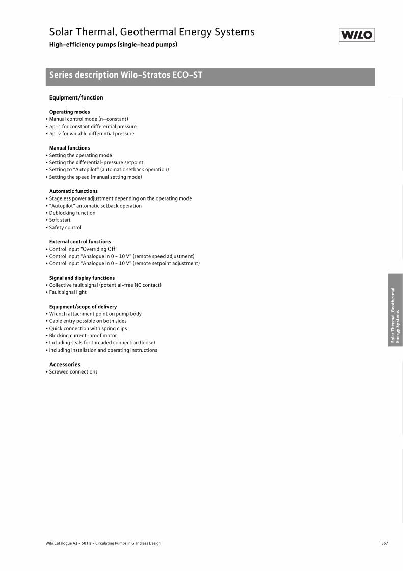
367
Solar Thermal, Geothermal Energy SystemsHigh-efficiency pumps (single-head pumps)
Series description Wilo-Stratos ECO-ST
Wilo Catalogue A1 - 50 Hz - Circulating Pumps in Glandless Design
Hea
ting,
Air-
cond
ition
ing,
Co
olin
gSe
cond
ary
Hot W
ater
Circ
ulat
ion
Sola
r The
rmal
, Geo
ther
mal
En
ergy
Sys
tem
sSe
rvic
e/Ac
cess
orie
s, S
yste
ms
Switc
hgea
rs a
nd C
ontr
ol
Dev
ices
Pum
p M
anag
emen
t Sys
tem
s
Equipment/function
Operating modes• Manual control mode (n=constant)• �p-c for constant differential pressure• �p-v for variable differential pressure
Manual functions• Setting the operating mode• Setting the differential-pressure setpoint• Setting to “Autopilot” (automatic setback operation)• Setting the speed (manual setting mode)
Automatic functions• Stageless power adjustment depending on the operating mode• “Autopilot” automatic setback operation• Deblocking function• Soft start• Safety control
External control functions• Control input “Overriding Off”• Control input “Analogue In 0 - 10 V” (remote speed adjustment) • Control input “Analogue In 0 - 10 V” (remote setpoint adjustment)
Signal and display functions• Collective fault signal (potential-free NC contact)• Fault signal light
Equipment/scope of delivery• Wrench attachment point on pump body• Cable entry possible on both sides• Quick connection with spring clips• Blocking current-proof motor• Including seals for threaded connection (loose)• Including installation and operating instructions
Accessories• Screwed connections

368 Subject to change without prior notice 09/2007 WILO AG
Solar Thermal, Geothermal Energy SystemsHigh-efficiency pumps (single-head pumps)
Technical data Wilo-Stratos-ECO-ST
Wilo-Stratos ECO-ST...
15/1-5-130 25/1-5 25/1-5-RG
Approved fluids (other fluids on request)
Heating water (as per VDI 2035) • • •Water/glycol mixtures (maximum 1:1; mixtures with more than 20 % glycol content require rechecking of the pumping data)
• • •
Secondary hot water and water for food businesses as per TrinkwV 2001 – – –
Performance
Maximum delivery head [m] 5 5 5
Maximum flow volume [m3/h] 2.5 2.5 2.5
Permitted field of application
Temperature range for utilisation in heating, ventila-tion & air conditioning systems
at maximum ambient temperature +25 °C [°C]at maximum ambient temperature +40 °C [°C]
+ 15 to + 110+ 15 to + 95
+ 15 to + 110+ 15 to + 95
+ 15 to + 110+ 15 to + 95
Temperature range for utilisation in secondary hot water circulation systems
at maximum ambient temperature +40 °C [°C]with maximum ambient temperature +40 °C inshort-term operation 2 h [°C]
–
–
–
–
–
–
Maximum permissible total hardness in secondary hot water-circulation systems [°d] – – –
Standard version with nominal pressure, pmax [bar] 10 10 10
Special version with nominal pressure, pmax [bar] – – –
Pipe connections
Thread connection ½ 1 1
Nominal flange diameter 15 25 25
Flange for counter flange PN 6, standard version – – –
Flange for counter flange PN 16, special version – – –
Combination flange PN 6/10 for counter flange PN 6 and PN 16, standard version – – –
Support-bracket mounting (with horizontal shaft only), standard version – – –
Support-bracket mounting (with horizontal shaft only), special version – – –
Electrical connection
Mains connection 1~ [V], standard version 230 230 230
Mains connection 3~ [V], standard version – – –
Mains connection 3~ [V], with optional switching plug – – –
Mains frequency [Hz] 50 50 50
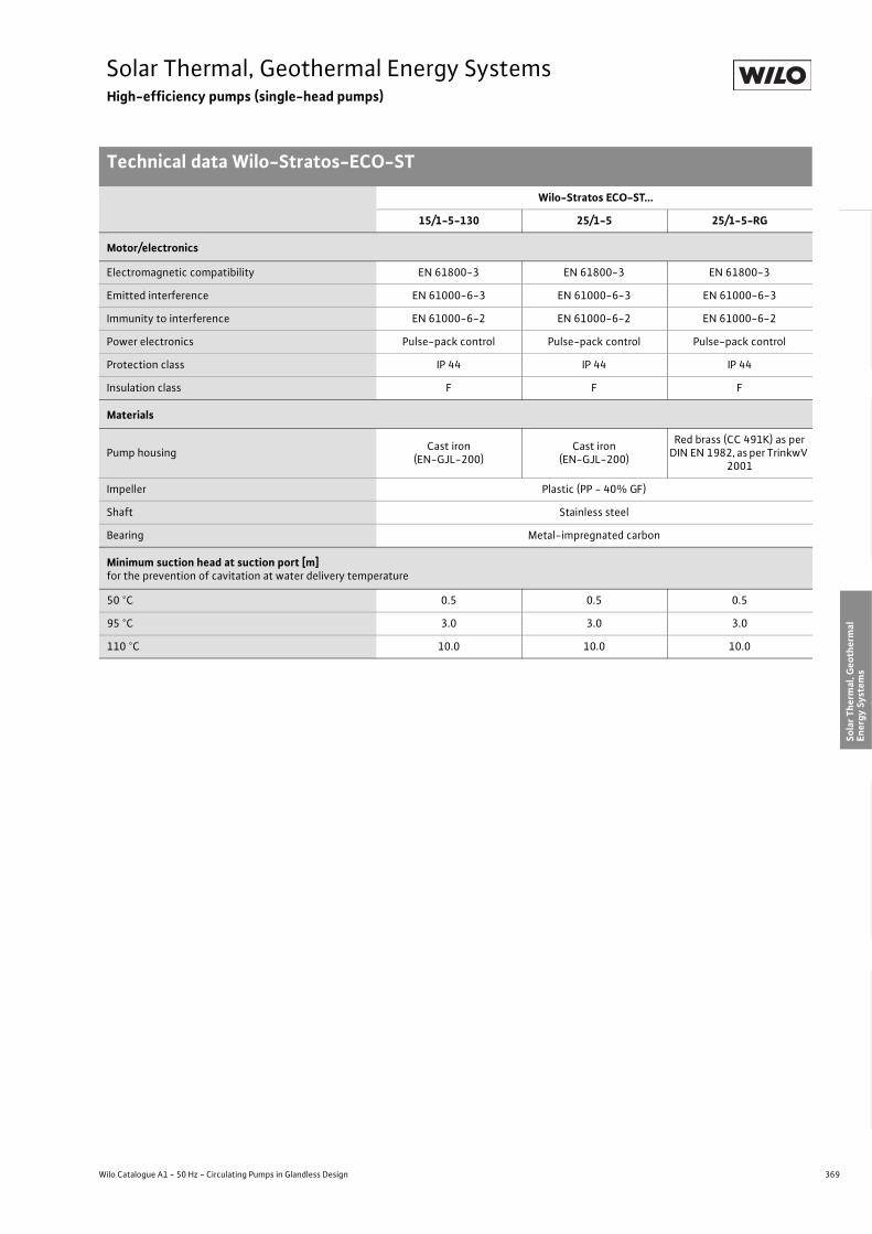
369
Solar Thermal, Geothermal Energy SystemsHigh-efficiency pumps (single-head pumps)
Technical data Wilo-Stratos-ECO-ST
Wilo Catalogue A1 - 50 Hz - Circulating Pumps in Glandless Design
Hea
ting,
Air-
cond
ition
ing,
Co
olin
gSe
cond
ary
Hot W
ater
Circ
ulat
ion
Sola
r The
rmal
, Geo
ther
mal
En
ergy
Sys
tem
sSe
rvic
e/Ac
cess
orie
s, S
yste
ms
Switc
hgea
rs a
nd C
ontr
ol
Dev
ices
Pum
p M
anag
emen
t Sys
tem
s
Motor/electronics
Electromagnetic compatibility EN 61800-3 EN 61800-3 EN 61800-3
Emitted interference EN 61000-6-3 EN 61000-6-3 EN 61000-6-3
Immunity to interference EN 61000-6-2 EN 61000-6-2 EN 61000-6-2
Power electronics Pulse-pack control Pulse-pack control Pulse-pack control
Protection class IP 44 IP 44 IP 44
Insulation class F F F
Materials
Pump housing Cast iron (EN-GJL-200)
Cast iron (EN-GJL-200)
Red brass (CC 491K) as per DIN EN 1982, as per TrinkwV
2001
Impeller Plastic (PP - 40% GF)
Shaft Stainless steel
Bearing Metal-impregnated carbon
Minimum suction head at suction port [m]for the prevention of cavitation at water delivery temperature
50 °C 0.5 0.5 0.5
95 °C 3.0 3.0 3.0
110 °C 10.0 10.0 10.0
Wilo-Stratos ECO-ST...
15/1-5-130 25/1-5 25/1-5-RG
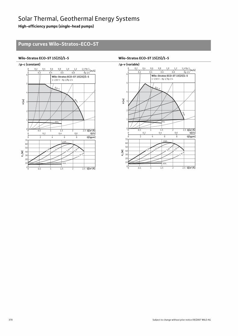
370 Subject to change without prior notice 09/2007 WILO AG
Solar Thermal, Geothermal Energy SystemsHigh-efficiency pumps (single-head pumps)
Pump curves Wilo-Stratos-ECO-ST
Wilo-Stratos ECO-ST 15(25)/1-5
�p-c (constant)
Wilo-Stratos ECO-ST 15(25)/1-5
�p-v (variable)
H [m
]
0
4
5
6
2
1
3
[m/s] 0 0,8 0,2 0,4
0,2 0 0,4 0,6 0,8 1,0 1,2 1,4
0,6
0 0,50 0,2 0,4 0,6
0 2 4 6 8
1 1,5 2 2,5
Q[m³/h]1,51 2,520 0,5
Q[m³/h]Ql/s]
Q[lgpm]
0
40
30
20
10
50
60
70
P 1 [W
]
Rp 1¼
Rp 1
max.
4 m 3 m 2 m
1 m
p-c
max.
min.
min.
5 m
Wilo-Stratos ECO-ST 15(25)/1-51~230 V - Rp 1/Rp 1¼
H [m
]
0
4
5
6
2
1
3
[m/s] 0 0,8 0,2 0,4
0,2 0 0,4 0,6 0,8 1,0 1,2 1,4
0,6
0 0,5 0 0,2 0,4 0,6
0 2 4 6 8
1 1,5 2 2,5
Q[m³/h]1,51 2,520 0,5
Q[m³/h]Q[l/s]
Q[lgpm]
0
40
30
20
10
50
60
70
P 1 [W
]
Rp 1¼
Rp 1
p-v
max.
min.
max.
4 m 3 m 2 m
1 m
5 m
min.
Wilo-Stratos ECO-ST 15(25)1-51~230 V - Rp 1/ Rp 1¼

371
Solar Thermal, Geothermal Energy SystemsHigh-efficiency pumps (single-head pumps)
Pump curves, terminal diagrams, motor data Wilo-Stratos-ECO-ST
Wilo Catalogue A1 - 50 Hz - Circulating Pumps in Glandless Design
Hea
ting,
Air-
cond
ition
ing,
Co
olin
gSe
cond
ary
Hot W
ater
Circ
ulat
ion
Sola
r The
rmal
, Geo
ther
mal
En
ergy
Sys
tem
sSe
rvic
e/Ac
cess
orie
s, S
yste
ms
Switc
hgea
rs a
nd C
ontr
ol
Dev
ices
Pum
p M
anag
emen
t Sys
tem
s
Terminal diagram
Single-phase AC motor (EM), 2-pole, 1~230 V, 50 Hz
Motor data
Wilo-Stratos ECO-ST... Speed Power consumption
Current maximum
Motor protection
Threaded cable connection
n P1 I - PG[1/min] [W] [A] - -
15/1-5-130 1400 - 3500 5.8 - 59 0.46not necessary
(blocking current-proof)
1x7/1x9/1x11
25/1-5 1400 - 3500 5.8 - 59 0.46not necessary
(blocking current-proof)
1x7/1x9/1x11
25/1-5-RG 1400 - 3500 5.8 - 59 0.46not necessary
(blocking current-proof)
1x7/1x9/1x11
0~10VL N PE SSM InExt. off
1~ 230 V, 50 Hz

372 Subject to change without prior notice 09/2007 WILO AG
Solar Thermal, Geothermal Energy SystemsHigh-efficiency pumps (single-head pumps)
Dimensions, weights Wilo-Stratos-ECO-ST
Dimension drawing
Dimensions, weights
Wilo-Stratos ECO-ST...
Screwed connection Thread Dimensions Weight
aboutRp G l0 l1 l3 l4 l5 a a2 b1 b2 b3 b4 b5 -- - [mm] [kg]
15/1-5-130 ½ 1 130 96 90 78 50 60 32.5 184.8 92.5 77.5 73 107.3 3.025/1-5 1 1½ 180 96 90 78 50 60 32.5 184.8 92.5 77.5 73 107.3 3.025/1-5-RG 1 1½ 180 96 90 78 50 60 32.5 184.8 92.5 77.5 73 107.3 3.0
b1
b3
b2
b5 G
a2
I4 I5
I1
I 0
l 3
b 4

373
Solar Thermal, Geothermal Energy SystemsHigh-efficiency pumps (single-head pumps)
Wilo Catalogue A1 - 50 Hz - Circulating Pumps in Glandless Design
Hea
ting,
Air-
cond
ition
ing,
Co
olin
gSe
cond
ary
Hot W
ater
Circ
ulat
ion
Sola
r The
rmal
, Geo
ther
mal
En
ergy
Sys
tem
sSe
rvic
e/Ac
cess
orie
s, S
yste
ms
Switc
hgea
rs a
nd C
ontr
ol
Dev
ices
Pum
p M
anag
emen
t Sys
tem
s

374 Subject to change without prior notice 09/2007 WILO AG
Solar Thermal, Geothermal Energy SystemsStandard pumps (single-head pumps)
Series overview Wilo-Star-ST, Wilo-Star-RSG
Series: Wilo-Star-ST
>Single-head pumps:• Circulating pumps with screwed connection>Application:• Solar thermal systems
Series: Wilo-Star-RSG
>Single-head pumps:• Circulating pumps with screwed connection>Application:• Geothermal systems, heating systems
0
2
4
6
8
0 0,5 1,0 1,5 2,0 2,5 3,0 Q [m³/h]
H [m
]
Wilo-Star ST
ST20(25)/4
ST20(25)/6
ST20/11ST20/9
ST25/7
0
1
2
3
4
5
6
7H[m]
0 1 2 3 4 5 Q [m³/h]
Wilo-STAR-RSG
Star-RSG 25/7, 30/7
Star-RSG 25/8, 30/8

375
Solar Thermal, Geothermal Energy SystemsStandard pumps (single-head pumps)
Series overview Wilo-Star-ST, Wilo-Star-RSG
Wilo Catalogue A1 - 50 Hz - Circulating Pumps in Glandless Design
Hea
ting,
Air-
cond
ition
ing,
Co
olin
gSe
cond
ary
Hot W
ater
Circ
ulat
ion
Sola
r The
rmal
, Geo
ther
mal
En
ergy
Sys
tem
sSe
rvic
e/Ac
cess
orie
s, S
yste
ms
Switc
hgea
rs a
nd C
ontr
ol
Dev
ices
Pum
p M
anag
emen
t Sys
tem
s
Series: Wilo-Star-ST
> Product advantages:• Special hydraulics for utilisation in solar thermal systems• Up to 30 % less current consumption due to class B motor technology• Pump housing with wrench attachment point• Pump housing with cataphoretic (KTL) coating for the prevention of corrosion from condensa-
tion formation
> Additional information: Page• Planning guide: . . . . . . . . . . . . . . . . . . 6• Equipment/function: . . . . . . . . . . . . . 376• Series description: . . . . . . . . . . . . . . . . 378• Technical data: . . . . . . . . . . . . . . . . . . . 380• Pump curves: . . . . . . . . . . . . . . . . . . . . 382• Terminal diagrams, motor data: . . . . 384• Dimensions, weights: . . . . . . . . . . . . . 385
Series: Wilo-Star-RSG
> Product advantages:• Special hydraulics for utilisation in geothermal systems• Pump housing with cataphoretic (KTL) coating for the prevention of corrosion from condensa-
tion formation
> Additional information: Page• Planning guide: . . . . . . . . . . . . . . . . . . 6• Equipment/function: . . . . . . . . . . . . . 376• Series description: . . . . . . . . . . . . . . . . 386• Technical data: . . . . . . . . . . . . . . . . . . . 388• Pump curves: . . . . . . . . . . . . . . . . . . . . 390• Terminal diagrams, motor data: . . . . 391• Dimensions, weights: . . . . . . . . . . . . . 392

376 Subject to change without prior notice 09/2007 WILO AG
Solar Thermal, Geothermal Energy SystemsStandard pumps (single-head pumps)
Equipment/function Wilo-Star-ST, Wilo-Star-RSG
Wilo-Star-ST Wilo-Star-RSG
Operating modes
Speed-stage switching • •Manual control mode (n=constant) – –
�p-c for constant differential pressure – –
�p-v for variable differential pressure – –
�p-T for temperature-prompted differential pressure – –
Manual functions
Setting the operating mode – –
Setting the differential-pressure setpoint – –
Setting to “Autopilot” (automatic setback operation) – –
Setting the pump to ON/OFF – –
Setting the speed (manual setting mode) – –
Setting the speed stages 3 3
Automatic functions
Stageless power adjustment depending on the operat-ing mode – –
“Autopilot” automatic setback operation – –
Deblocking function – –
Soft start – –
Safety control – –
Full motor protection with integrated trip electronics – –
External control functions
Control input “Overriding Off” – –
Control input “Overriding Min” – –
Control input “Analogue In 0 - 10 V” (remote speed adjustment) – –
Control input “Analogue in 0 - 10 V” (remote setpoint adjustment) – –
Signal and display functions
Single fault signal (potential-free NC contact) – –
Collective fault signal (potential-free NC contact) – –
Single/collective run signal (potential-free NO contact) – –
Thermal winding contact (WSK, potential-free NC con-tact) – –
• = available, – = not available
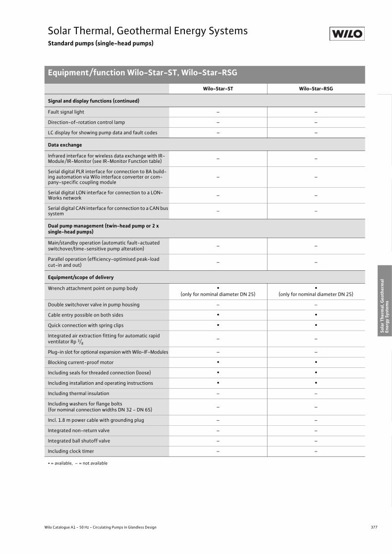
377
Solar Thermal, Geothermal Energy SystemsStandard pumps (single-head pumps)
Equipment/function Wilo-Star-ST, Wilo-Star-RSG
Wilo Catalogue A1 - 50 Hz - Circulating Pumps in Glandless Design
Hea
ting,
Air-
cond
ition
ing,
Co
olin
gSe
cond
ary
Hot W
ater
Circ
ulat
ion
Sola
r The
rmal
, Geo
ther
mal
En
ergy
Sys
tem
sSe
rvic
e/Ac
cess
orie
s, S
yste
ms
Switc
hgea
rs a
nd C
ontr
ol
Dev
ices
Pum
p M
anag
emen
t Sys
tem
s
Signal and display functions (continued)
Fault signal light – –
Direction-of-rotation control lamp – –
LC display for showing pump data and fault codes – –
Data exchange
Infrared interface for wireless data exchange with IR-Module/ IR-Monitor (see IR-Monitor Function table) – –
Serial digital PLR interface for connection to BA build-ing automation via Wilo interface converter or com-pany-specific coupling module
– –
Serial digital LON interface for connection to a LON-Works network – –
Serial digital CAN interface for connection to a CAN bus system – –
Dual pump management (twin-head pump or 2 x single-head pumps)
Main/standby operation (automatic fault-actuated switchover/time-sensitive pump alteration) – –
Parallel operation (efficiency-optimised peak-load cut-in and out) – –
Equipment/scope of delivery
Wrench attachment point on pump body •(only for nominal diameter DN 25)
•(only for nominal diameter DN 25)
Double switchover valve in pump housing – –
Cable entry possible on both sides • •Quick connection with spring clips • •Integrated air extraction fitting for automatic rapid ventilator Rp 3/8
– –
Plug-in slot for optional expansion with Wilo-IF-Modules – –
Blocking current-proof motor • •Including seals for threaded connection (loose) • •Including installation and operating instructions • •Including thermal insulation – –
Including washers for flange bolts(for nominal connection widths DN 32 - DN 65) – –
Incl. 1.8 m power cable with grounding plug – –
Integrated non-return valve – –
Integrated ball shutoff valve – –
Including clock timer – –
Wilo-Star-ST Wilo-Star-RSG
• = available, – = not available

378 Subject to change without prior notice 09/2007 WILO AG
Solar Thermal, Geothermal Energy SystemsStandard pumps (single-head pumps)
Series description Wilo-Star-ST
Wilo-Star-ST
ConstructionGlandless circulating pump with screwed connection. Preselectable speed stages for power adjustment
ApplicationHigh-flow volume and low-flow volume solar thermal systems
Type keyExample: Wilo-Star-ST 25/6Star Standard pump (screw-end pump)-ST Version for solar thermal applications25/ Nominal connection width6 Nominal delivery head [m]
Special features/product advantages• Special hydraulics for utilisation in solar thermal systems• Up to 30 % less current consumption due to class B motor techno-
logy• Pump housing with wrench attachment point• Pump housing with cataphoretic (KTL) coating for the prevention of
corrosion from condensation formation
00
1
2
3
4
5
6
7
8
9
10
11
H[m]
0,5 1 21,5 Q[m³/h]2,5 3
Wilo-Star-ST
ST 20/11
ST 20/9
ST 25/7ST 20(25)/6
ST 20(25)/4

379
Solar Thermal, Geothermal Energy SystemsStandard pumps (single-head pumps)
Series description Wilo-Star-ST
Wilo Catalogue A1 - 50 Hz - Circulating Pumps in Glandless Design
Hea
ting,
Air-
cond
ition
ing,
Co
olin
gSe
cond
ary
Hot W
ater
Circ
ulat
ion
Sola
r The
rmal
, Geo
ther
mal
En
ergy
Sys
tem
sSe
rvic
e/Ac
cess
orie
s, S
yste
ms
Switc
hgea
rs a
nd C
ontr
ol
Dev
ices
Pum
p M
anag
emen
t Sys
tem
s
Equipment/function
Operating modes• Speed-stage switching
Manual functions• Setting the speed stages: 3 speed stages
Equipment/scope of delivery• Spanner grip on the pump body (only with nominal diameter DN 25)• Cable entry possible on both sides• Quick connection with spring clips• Blocking current-proof motor• Including seals for threaded connection (loose)• Including installation and operating instructions
Accessories• Screwed connections• Thermal insulation shells for Wilo-Star-ST 25
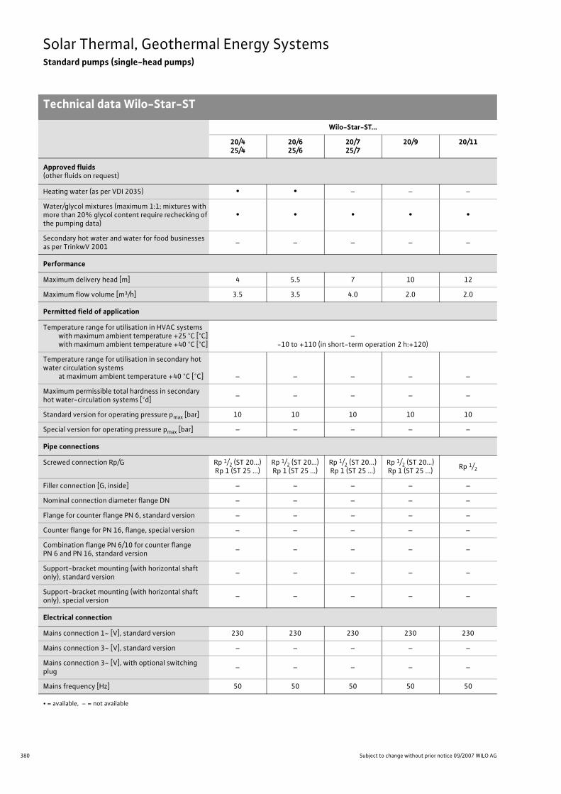
380 Subject to change without prior notice 09/2007 WILO AG
Solar Thermal, Geothermal Energy SystemsStandard pumps (single-head pumps)
Technical data Wilo-Star-ST
Wilo-Star-ST...
20/425/4
20/625/6
20/725/7
20/9 20/11
Approved fluids(other fluids on request)
Heating water (as per VDI 2035) • • – – –
Water/glycol mixtures (maximum 1:1; mixtures with more than 20% glycol content require rechecking of the pumping data)
• • • • •
Secondary hot water and water for food businesses as per TrinkwV 2001 – – – – –
Performance
Maximum delivery head [m] 4 5.5 7 10 12
Maximum flow volume [m3/h] 3.5 3.5 4.0 2.0 2.0
Permitted field of application
Temperature range for utilisation in HVAC systemswith maximum ambient temperature +25 °C [°C]with maximum ambient temperature +40 °C [°C]
–-10 to +110 (in short-term operation 2 h:+120)
Temperature range for utilisation in secondary hot water circulation systems
at maximum ambient temperature +40 °C [°C] – – – – –
Maximum permissible total hardness in secondary hot water-circulation systems [°d] – – – – –
Standard version for operating pressure pmax [bar] 10 10 10 10 10
Special version for operating pressure pmax [bar] – – – – –
Pipe connections
Screwed connection Rp/G Rp 1/2 (ST 20...)Rp 1 (ST 25 ...)
Rp 1/2 (ST 20...)Rp 1 (ST 25 ...)
Rp 1/2 (ST 20...)Rp 1 (ST 25 ...)
Rp 1/2 (ST 20...)Rp 1 (ST 25 ...) Rp 1/2
Filler connection [G, inside] – – – – –
Nominal connection diameter flange DN – – – – –
Flange for counter flange PN 6, standard version – – – – –
Counter flange for PN 16, flange, special version – – – – –
Combination flange PN 6/10 for counter flange PN 6 and PN 16, standard version – – – – –
Support-bracket mounting (with horizontal shaft only), standard version – – – – –
Support-bracket mounting (with horizontal shaft only), special version – – – – –
Electrical connection
Mains connection 1~ [V], standard version 230 230 230 230 230
Mains connection 3~ [V], standard version – – – – –
Mains connection 3~ [V], with optional switching plug – – – – –
Mains frequency [Hz] 50 50 50 50 50
• = available, – = not available

381
Solar Thermal, Geothermal Energy SystemsStandard pumps (single-head pumps)
Technical data Wilo-Star-ST
Wilo Catalogue A1 - 50 Hz - Circulating Pumps in Glandless Design
Hea
ting,
Air-
cond
ition
ing,
Co
olin
gSe
cond
ary
Hot W
ater
Circ
ulat
ion
Sola
r The
rmal
, Geo
ther
mal
En
ergy
Sys
tem
sSe
rvic
e/Ac
cess
orie
s, S
yste
ms
Switc
hgea
rs a
nd C
ontr
ol
Dev
ices
Pum
p M
anag
emen
t Sys
tem
s
Motor/electronics
Electromagnetic compatibility – – – – –
Emitted interference EN 61000-6-3
Immunity to interference EN 61000-6-2
Power electronics – – – – –
Radio interference suppression level N N N N N
Protection class IP 44 IP 44 IP 44 IP 44 IP 44
Insulation class F F F F F
Materials
Pump housing Cast iron (EN-GJL-200), cataphoretic painting
Impeller Polypropylene
Shaft Stainless steel (X40 Cr13)
Bearing Carbon
Minimum suction head [m]
for water delivery temperature of 50 °C 0.5 0.5 0.5 0.5 0.5
for water delivery temperature of 95 °C 3 3 3 3 3
for water delivery temperature of 110 °C 10 10 10 10 10
Wilo-Star-ST...
20/425/4
20/625/6
20/725/7
20/9 20/11
• = available, – = not available

382 Subject to change without prior notice 09/2007 WILO AG
Solar Thermal, Geothermal Energy SystemsStandard pumps (single-head pumps)
Pump curves Wilo-Star-ST
Wilo-Star ST 20/4, ST 25/4 Wilo-Star ST 20/6, ST 25/6
Wilo-Star ST 20/7, ST 25/7 Wilo-Star ST 20/9
0 0,4 0,8 1,2 1,6
Q[m³/h]0 0,5 1,0 1,5 2,0 2,5 3,0
Q[l/s]0 0,2 0,4 0,6 0,8 1,0
Q[Igpm]0 2 4 6 8 10
H[m]
0
1
2
3
4
Q[m³/h]0 0,5 1,0 1,5 2,0 2,5 3,0
P1[W]
0
20
40
Q[m/s]
v0 1 2 3 4 5 Rp½
Rp1
Wilo-Star-ST20/4, 25/41~230 V - Rp ½ / Rp 1
max.
min.
6Q[m/s]
v
0 0,5 1,0 1,5 2,0
Q[m³/h]0 1 2 3 4
Q[l/s]0 0,2 0,4 0,6 0,8 1,0 1,2
Q[Igpm]0 4 8 12
H[m]
0
1
2
3
4
5
6
Q[m³/h]0 1 2 3 4
P1[W]
0
40
0 1 2 3 4 5 Rp½
Rp1
Wilo-Star-ST20/6, 25/61~230 V - Rp ½ / Rp 1
max.
min.
Q
0,50
00
0
0
[l/s]
[lgpm ]
040
0,75
1,0
[m/s]
1
2
5
v1,0 1,5
105
120
100
80
1,0 2,0 3,0
0,25 0,5 1,0
2,0 3,0
4
3
6
max.
min.
60
7
min.
max.
2,0
Wilo-Star ST 20/7ST 25/7
1~230 V - Rp 1/2, Rp 1
[m3/h]
[m3/h]
P 1[W]
H[m
]
140
120
100
80
60
40
20
0 0,1 0,2 0,3 0,4 0,5 0,6 0,7
0 0,2 0,4 0,6 0,8
0 0,5 1 1,5
0 0,5 1 1,5 2 2,5
v [m/s]
Q
[m3/h]
[lgpm]
12
10
8
6
4
2
0
[l/s]
Wilo-Star ST 20/91 ~ 230 V - Rp 1/2
[m3/h]
max.
min
max.
min
0 0,5 1 1,5 2 2,5
P 1[W]
H[m
]

383
Solar Thermal, Geothermal Energy SystemsStandard pumps (single-head pumps)
Pump curves Wilo-Star-ST
Wilo Catalogue A1 - 50 Hz - Circulating Pumps in Glandless Design
Hea
ting,
Air-
cond
ition
ing,
Co
olin
gSe
cond
ary
Hot W
ater
Circ
ulat
ion
Sola
r The
rmal
, Geo
ther
mal
En
ergy
Sys
tem
sSe
rvic
e/Ac
cess
orie
s, S
yste
ms
Switc
hgea
rs a
nd C
ontr
ol
Dev
ices
Pum
p M
anag
emen
t Sys
tem
s
Wilo-Star ST 20/11
Q
max.
[m3/h]
0 0,1 0,2 0,3 0,4 0,5 0,6 0,7
0 0,2 0,4 0,6 0,8
0 0,5 1 1,5
0 0,5 1 1,5 2 2,5
v [m/s]
[m3/h]
[lgpm]
12
10
8
6
4
2
0
[l/s]
Wilo-Star ST 20/111 ~ 230 V - Rp 1/2
max.
min
0 0,5 1 1,5 2 2,5
180
160
140
120
100
80
60
min
P 1[W]
H[m
]

384 Subject to change without prior notice 09/2007 WILO AG
Solar Thermal, Geothermal Energy SystemsStandard pumps (single-head pumps)
Terminal diagrams, motor data Wilo-Star-ST
Always refer to name plate data!
Terminal diagram
1-phase motor (EM) 2-pole - 1~230 V, 50 Hz,with integrated capacitor
Motor data
Wilo-Star-ST... Nominal power Stage/speed Power consumption
Current Capacitor Threaded cable connection
Motor protection
P2 n P1 I Capacity PG –[W] [1/min] [W] [A] [�F/VDB] – –
20/417.5011.50
6.50
max.
min.
272026302350
483828
0.210.170.13
1.7/400 1 x 11not necessary
(blocking current-proof)
20/626.0017.5010.50
max.
min.
275026502350
635441
0.280.230.18
2.0/400 1 x 11not necessary
(blocking current-proof)
20/759.2031.2014.80
max.
min.
270726042170
1108159
0.300.240.16
3.5/400 1 x 11not necessary
(blocking current-proof)
20/939.5023.0013.00
max.
min.
253521221564
1107850
0.500.340.23
3.0/400 1 x 11not necessary
(blocking current-proof)
20/1159.2031.2014.80
max.
min.
248119991448
165115
75
0.720.520.32
3.5/400 1 x 11not necessary
(blocking current-proof)
25/417.5011.50
6.50
max.
min.
272026302350
483828
0.210.170.13
1.7/400 1 x 11not necessary
(blocking current-proof)
25/626.0017.5010.50
max.
min.
275026502350
635441
0.280.230.18
2.0/400 1 x 11not necessary
(blocking current-proof)
25/759.2031.2014.80
max.
min.
270726042170
1108159
0.300.240.16
3.5/400 1 x 11not necessary
(blocking current-proof)
L N PE
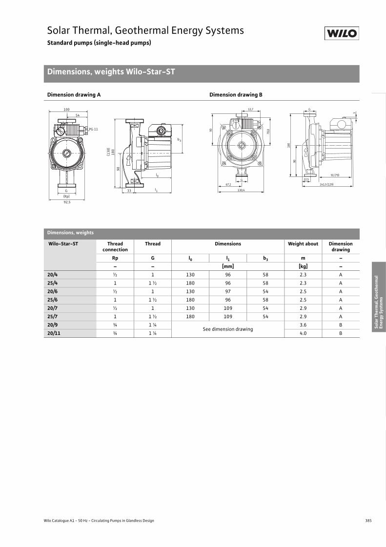
385
Solar Thermal, Geothermal Energy SystemsStandard pumps (single-head pumps)
Dimensions, weights Wilo-Star-ST
Wilo Catalogue A1 - 50 Hz - Circulating Pumps in Glandless Design
Hea
ting,
Air-
cond
ition
ing,
Co
olin
gSe
cond
ary
Hot W
ater
Circ
ulat
ion
Sola
r The
rmal
, Geo
ther
mal
En
ergy
Sys
tem
sSe
rvic
e/Ac
cess
orie
s, S
yste
ms
Switc
hgea
rs a
nd C
ontr
ol
Dev
ices
Pum
p M
anag
emen
t Sys
tem
s
Dimension drawing A Dimension drawing B
Dimensions, weights
Wilo-Star-ST Thread connection
Thread Dimensions Weight about Dimension drawing
Rp G l0 l1 b3 m –– – [mm] [kg] –
20/4 ½ 1 130 96 58 2.3 A
25/4 1 1 ½ 180 96 58 2.3 A
20/6 ½ 1 130 97 54 2.5 A
25/6 1 1 ½ 180 96 58 2.5 A
20/7 ½ 1 130 109 54 2.9 A
25/7 1 1 ½ 180 109 54 2.9 A
20/9 ¾ 1 ¼See dimension drawing
3.6 B
20/11 ¾ 1 ¼ 4.0 B
180
l0
b3
l1
90
92,5
100
PG 11
54
33G
(Rp)
(130
)53,7
90
78,8
67,2
130,4
G
180
90
91 (79)
3
141,5 (129)
22,5G

386 Subject to change without prior notice 09/2007 WILO AG
Solar Thermal, Geothermal Energy SystemsStandard pumps (single-head pumps)
Series description Wilo-Star-RSG
Wilo-Star-RSG
ConstructionGlandless circulating pump with screwed connection. Preselectable speed stages for power adjustment
ApplicationGeothermal systems, heating systems
Type keyExample: Wilo-Star-RSG 25/7Star Standard pump (screw-end pump)-RSG Version for geothermal systems25/ Nominal connection width7 Nominal delivery head [m]
Special features/product advantages• Special hydraulics for utilisation in geothermal systems• Pump housing with cataphoretic (KTL) coating for the prevention of
corrosion from condensation formation
Q[m³/h]0,1 0,2 0,3 0,4 0,5 0,6 0,8 1,0 2 3 4 5
H[m]
0
1
2
3
4
5
6
7
8
Star-RSG 25/8, 30/8
Star-RSG 25/7, 30/7
Wilo-Star-RSG
387
Solar Thermal, Geothermal Energy SystemsStandard pumps (single-head pumps)
Series description Wilo-Star-RSG
Wilo Catalogue A1 - 50 Hz - Circulating Pumps in Glandless Design
Hea
ting,
Air-
cond
ition
ing,
Co
olin
gSe
cond
ary
Hot W
ater
Circ
ulat
ion
Sola
r The
rmal
, Geo
ther
mal
En
ergy
Sys
tem
sSe
rvic
e/Ac
cess
orie
s, S
yste
ms
Switc
hgea
rs a
nd C
ontr
ol
Dev
ices
Pum
p M
anag
emen
t Sys
tem
s
Equipment/function
Operating modes• Speed-stage switching
Equipment/scope of delivery• Spanner grip on the pump body (only with nominal diameter DN 25)• Cable entry possible on both sides• Quick connection with spring clips• Blocking current-proof motor• Including seals for threaded connection (loose)• Including installation and operating instructions
Accessories• Screwed connections• Thermal insulation shells

388 Subject to change without prior notice 09/2007 WILO AG
Solar Thermal, Geothermal Energy SystemsStandard pumps (single-head pumps)
Technical data Wilo-Star-RSG
Wilo-Star-RSG...
25/7 30/7 25/8 30/8
Approved fluids(other fluids on request)
Heating water (as per VDI 2035) • • • •Water/glycol mixtures (maximum 1:1; mixtures with more than 20% glycol content require rechecking of the pumping data)
• • • •
Secondary hot water and water for food businesses as per TrinkwV 2001 – – – –
Performance
Maximum delivery head [m] 7 7 8 8.5
Maximum flow volume [m3/h] 5.5 5.5 5.5 5.5
Permitted field of application
Temperature range for utilisation in HVAC systemswith maximum ambient temperature +25 °C [°C]with maximum ambient temperature +40 °C [°C]
–- 10 to + 110
Temperature range for utilisation in secondary hot water circulation systems
at maximum ambient temperature +40 °C [°C] –
Maximum permissible total hardness in secondary hot water-circulation systems [°d] – – – –
Standard version for operating pressure pmax [bar] 10 10 10 10
Special version for operating pressure pmax [bar] – – – –
Pipe connections
Screwed connection Rp/G Rp 1 Rp 1 1/4 Rp 1 Rp 1 1/4
Filler connection [G, inside] – – – –
Nominal connection diameter flange DN – – – –
Flange for counter flange PN 6, standard version – – – –
Counter flange for PN 16, flange, special version – – – –
Combination flange PN 6/10 for counter flange PN 6 and PN 16, standard version – – – –
Support-bracket mounting (with horizontal shaft only), standard version – – – –
Support-bracket mounting (with horizontal shaft only), special version – – – –
Electrical connection
Mains connection 1~ [V], standard version 230 230 230 230
Mains connection 3~ [V], standard version – – – –
Mains connection 3~ [V], with optional switching plug – – – –
Mains frequency [Hz] 50 50 50 50
• = available, – = not available

389
Solar Thermal, Geothermal Energy SystemsStandard pumps (single-head pumps)
Technical data Wilo-Star-RSG
Wilo Catalogue A1 - 50 Hz - Circulating Pumps in Glandless Design
Hea
ting,
Air-
cond
ition
ing,
Co
olin
gSe
cond
ary
Hot W
ater
Circ
ulat
ion
Sola
r The
rmal
, Geo
ther
mal
En
ergy
Sys
tem
sSe
rvic
e/Ac
cess
orie
s, S
yste
ms
Switc
hgea
rs a
nd C
ontr
ol
Dev
ices
Pum
p M
anag
emen
t Sys
tem
s
Motor/electronics
Electromagnetic compatibility EN 61800-3
Emitted interference EN 61000-6-3
Immunity to interference EN 61000-6-2
Power electronics – – – –
Radio interference suppression level – – – –
Protection class IP 44 IP 44 IP 44 IP 44
Insulation class F F F F
Materials
Pump housing Cast iron (EN-GJL-200)
Impeller Plastic (PP - 40% GF)
Fibreglass-reinforced PP
Plastic (PP - 40% GF)
Shaft Stainless steel (X40 Cr13)
Bearing Metal-impregnated carbon Carbon Metal-impregnated carbon
Minimum suction head [m]
For water delivery temperature of 50 °C 0.5 0.5 0.5 0.5
For water delivery temperature of 95 °C 3.0 3.0 3.0 3.0
For water delivery temperature of 110 °C 10.0 10.0 10.0 10.0
Wilo-Star-RSG...
25/7 30/7 25/8 30/8
• = available, – = not available

390 Subject to change without prior notice 09/2007 WILO AG
Solar Thermal, Geothermal Energy SystemsStandard pumps (single-head pumps)
Pump curves Wilo-Star-RSG
Wilo-Star-RSG 25/7, 30/7 Wilo-Star-RSG 25/8, 30/8
Q[m³/h]Q[l/s]0 0,4 0,8 1,2 1,6
Q[Igpm]0 84 12 2016
H[m]
0
2
4
6
8
Q[m³/h]0 1 2 3 4 5 6
P1[W]
0
50
100
150
0 1 2 3 4 5 6
Wilo - Star-RSG 25/7, 30/71~230 V - Rp 1 / Rp 1¼
max.
min.
[m/s]0 0,5 1,0 1,5 2,0
v0 0,5 1,0 1,5 2,0 2,5 3,0 Rp1
Rp1¼
Q[m³/h]0 2 3 4 51 6Q[l/s]0 0,4 0,8 1,2 1,6
Q[Igpm]0 4 8 12 16
H[m]
0
2
4
6
8
Q[m³/h]0 1 2 3 4 5 6
P1[W]
0
50
100
150
Wilo - Star-RSG 25/8, 30/81~230 V - Rp 1 / Rp 1¼
v
[m/s]0 0,5 1,0 1,5 2,0
0 0,5 1,0 1,5 2,0 2,5 3,0 Rp1
Rp1¼
max.
min.
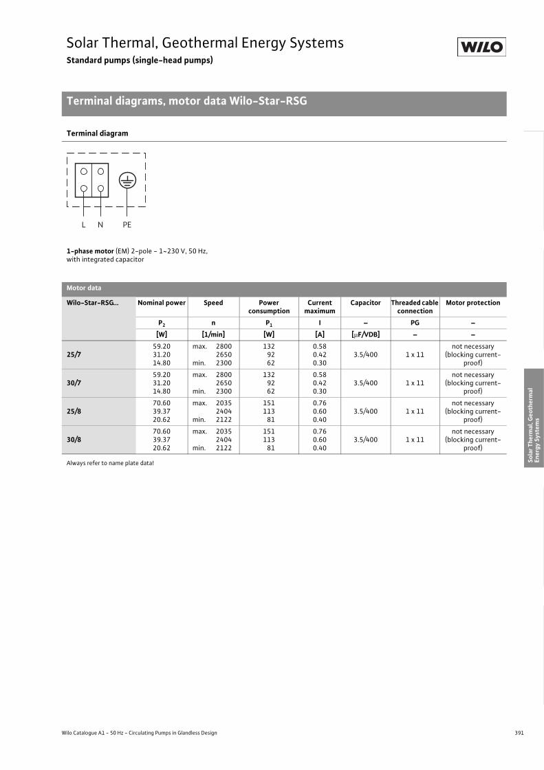
391
Solar Thermal, Geothermal Energy SystemsStandard pumps (single-head pumps)
Terminal diagrams, motor data Wilo-Star-RSG
Wilo Catalogue A1 - 50 Hz - Circulating Pumps in Glandless Design
Hea
ting,
Air-
cond
ition
ing,
Co
olin
gSe
cond
ary
Hot W
ater
Circ
ulat
ion
Sola
r The
rmal
, Geo
ther
mal
En
ergy
Sys
tem
sSe
rvic
e/Ac
cess
orie
s, S
yste
ms
Switc
hgea
rs a
nd C
ontr
ol
Dev
ices
Pum
p M
anag
emen
t Sys
tem
s
Always refer to name plate data!
Terminal diagram
1-phase motor (EM) 2-pole - 1~230 V, 50 Hz,with integrated capacitor
Motor data
Wilo-Star-RSG... Nominal power Speed Power consumption
Current maximum
Capacitor Threaded cable connection
Motor protection
P2 n P1 I – PG –[W] [1/min] [W] [A] [�F/VDB] – –
25/759.2031.2014.80
max.
min.
280026502300
1329262
0.580.420.30
3.5/400 1 x 11not necessary
(blocking current-proof)
30/759.2031.2014.80
max.
min.
280026502300
1329262
0.580.420.30
3.5/400 1 x 11not necessary
(blocking current-proof)
25/870.6039.3720.62
max.
min.
203524042122
151113
81
0.760.600.40
3.5/400 1 x 11not necessary
(blocking current-proof)
30/870.6039.3720.62
max.
min.
203524042122
151113
81
0.760.600.40
3.5/400 1 x 11not necessary
(blocking current-proof)
L N PE
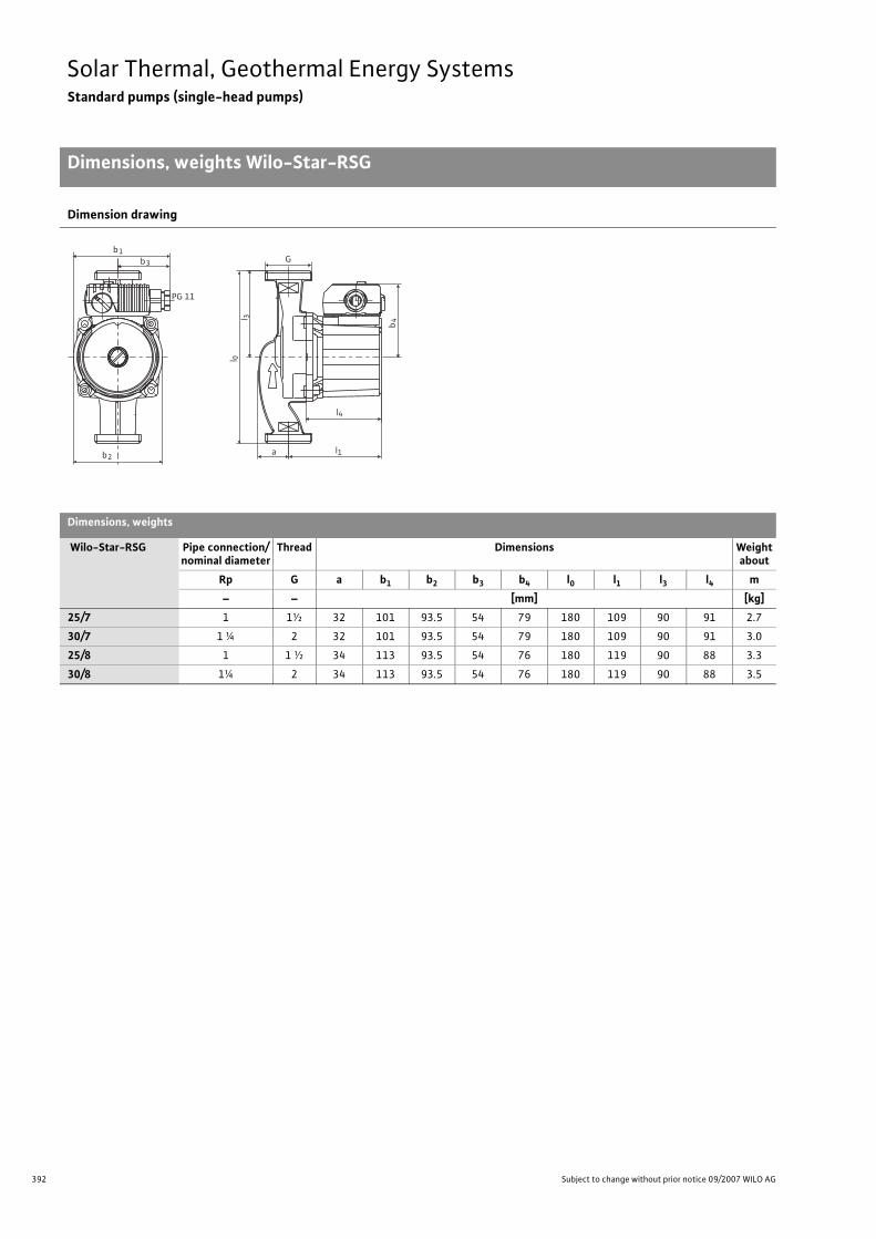
392 Subject to change without prior notice 09/2007 WILO AG
Solar Thermal, Geothermal Energy SystemsStandard pumps (single-head pumps)
Dimensions, weights Wilo-Star-RSG
Dimension drawing
Dimensions, weights
Wilo-Star-RSG Pipe connection/nominal diameter
Thread Dimensions Weightabout
Rp G a b1 b2 b3 b4 l0 l1 l3 l4 m– – [mm] [kg]
25/7 1 1½ 32 101 93.5 54 79 180 109 90 91 2.7
30/7 1 ¼ 2 32 101 93.5 54 79 180 109 90 91 3.0
25/8 1 1 ½ 34 113 93.5 54 76 180 119 90 88 3.3
30/8 1¼ 2 34 113 93.5 54 76 180 119 90 88 3.5
b2
b1
b4
l 0
l1
l4
l 3
G
PG 11
b3
a
393
Service/AccessoriesContents
Wilo Catalogue A1 - 50 Hz - Circulating Pumps in Glandless Design
Hea
ting,
Air-
cond
ition
ing,
Co
olin
gSe
cond
ary
Hot W
ater
Circ
ulat
ion
Sola
r The
rmal
, Geo
ther
mal
En
ergy
Sys
tem
sSe
rvic
e/Ac
cess
orie
s, S
yste
ms
Switc
hgea
rs a
nd C
ontr
ol
Dev
ices
Pum
p M
anag
emen
t Sys
tem
s
Service/accessories
Wilo-TOP motor technology 394
Circuit diagrams 396
Switching plug/servicing apparatus 400
Threaded pipe unions 401
Adapter fittings Wilo-(R), Wilo-(RF), Wilo-(F) 403
Pump thermal insulation 405
Cold water insulation for pumps Wilo-ClimaForm 406

394 Subject to change without prior notice 09/2007 WILO AG
Service/AccessoriesWilo-TOP motor technology
Motor technology
Motor technologyThe basis for the entire Wilo-TOP series is the motor conception. The so-called “Cold Motor” concept is based on optimised rotor and sta-tor configurations in conjunction with similarly optimised motor mechanics and an electrical connecting technology with chamber block contacts.The conventional insulating materials of Classes F and H are fully suf-ficient due to the minor electrical losses and resulting lower heat generation.
Electrical connectionWilo-TOP-S, TOP-SD, Wilo-TOP-D, Wilo-TOP-Z, Wilo-SE, Wilo-SE-TW, Wilo-RLThe single-phase AC motors and also the three-phase motors are each conceived as “voltage range motors” for European voltage.
- Single-phase AC motor:1~230 V, 50 Hz, tolerance as per DIN IEC 60038: ± 10%Connection also permitted to AC networks 1~220 Volt, 50 Hz.
- Three-phase motor:3~400 V, 50 Hz, tolerance as per DIN IEC 60038: ± 10%Connection also permitted to three-phase networks 3~380 Volt, 50 Hz.Connection to 3~230 V networks is possible with Wilo-TOP-S/-SD and Wilo-TOP-Z when the 3~230 V switching plug is used as an accessory. Connection to 3~230 V networks is possible with TOP-D by means of winding switch-over in the terminal box.
Wilo-TOP-E and Wilo-TOP-EDThe Wilo-TOP-E/-ED series has a three-phase motor starting with P2 = 350 W. Integration of the 1-phase micro-frequency converter requires connections to AC mains power.Electrical connection: 1~230 V, 50 Hz, tolerance as per DIN IEC 60038: ± 10%It is possible in three-phase networks with 3~230 V to connect Wilo-TOP-E/-ED series pumps between 2 phases.ATTENTION:For operating the Wilo pumps with control devices or modular acces-sories, the electrical operating conditions as per VDE 0160 are to be observed (for details, see planning guide).
Direction of rotation controlThe integrated electronic direction of rotation control displays the correct direction of rotation with the Wilo-TOP three-phase pumps when the direction of rotation control lamp lights up and the incor-rect one when it goes out.
Rotor unitThe integration of all components that rotate and come into contact with water in the compact rotor unit ensures maximum smooth oper-ation, long service life and ease of handling during service work.
ATTENTION:No pump ventilation necessary for commissioning, because forced ventilation takes place through a special borehole in the shaft during operation of the Wilo-TOP Pumps (see illustration).
Motor protection Wilo-TOP seriesMotor fuse protection is ensured as follows with Wilo-TOP Pumps.
Blocking current-proof motors: no motor protection requiredThe motors are designed in such a way that the windings are not damaged in the event of overload. This applies to the Wilo-TOP-D in three-phase/single phase AC version with nominal motor power P2 = 20 W.
Pumps with internal protection against unacceptably high winding temperaturesThe motors are designed in such a way that motor voltage is shut down internally in the event of overload and winding damage is thereby prevented. This applies for the pump typesWilo-TOP-S/-SDWilo-ZWilo-RLWilo-SE/SE-TWin both single-phase and in three-phase version with nominal motor power 50 W � P2 � 100 W. An automatic restart takes place in the single-phase versions after the coil has cooled down, the three-phase versions are acknowledged by switching the mains voltage off and then back on.
Pumps with full motor protection (WSK) and Wilo relay SK 602/622Realisation of full motor protection by means of thermal winding contacts (WSK) placed within the stator windings. This applies for TOP-S/-SD/-D/-Z AC pumps with rated motor power of P2 = 180 W, TOP-D three-phase pumps with P2 � 60 W.
Water
Rotor shaft / pump shaftAir venting

395
Service/AccessoriesWilo-TOP motor technology
Motor technology
Wilo Catalogue A1 - 50 Hz - Circulating Pumps in Glandless Design
Hea
ting,
Air-
cond
ition
ing,
Co
olin
gSe
cond
ary
Hot W
ater
Circ
ulat
ion
Sola
r The
rmal
, Geo
ther
mal
En
ergy
Sys
tem
sSe
rvic
e/Ac
cess
orie
s, S
yste
ms
Switc
hgea
rs a
nd C
ontr
ol
Dev
ices
Pum
p M
anag
emen
t Sys
tem
s
Pumps with integrated full motor protection including trip electronics
Patented motor protection with integrated triggering mechanism in the terminal box are equipped as standard in all Wilo-TOP-S/-SD/-Z three-phase pumps starting with P2 � 180 Watt, in all Wilo-S/SD AC pumps starting with P2 � 350 Watt, and in all Wilo-TOP-E/-ED pumps.Permanent full motor protection by way of exact motor temperature monitoring:
- TOP-E/-ED: 3 PTC thermistor sensors (PTC) in the windingTOP-S/-SD/-Z: 2 thermal winding contacts (WSK) in the winding
(for P2 � 180 W)In the event of disruption, e.g. when blocking, 2-phase running, etc. causes impermissible motor heating, a three-pole shutdown in the terminal box of the pump motor ensues with Wilo-TOP-S/-SD/-Z or the frequency converter is switched off with Wilo-TOP-E/-ED. They must be reset by actuating the cancel button on the terminal box.
Fault indication/signalStandard series integrated signals at the terminal box with
- Fault signal light- Collective fault signal (P2 � 180 Watt) with potential-free NC contact
as per VDI 3814 for Wilo-TOP three-phase pumps (not TOP-D) and Wilo-TOP-E/-ED pumps.
Electronics Supply voltage
Trip mechanismin the terminal box
Heating PTC
Bimetal washer (leaf spring) will be heated via PTC in case of fault
Bimetal switch
Thermal windingcontact (WSK)opens in case of thermal winding overtemperature
Motor
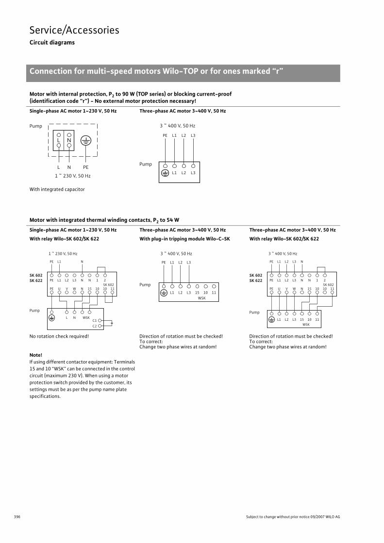
396 Subject to change without prior notice 09/2007 WILO AG
Service/AccessoriesCircuit diagrams
Connection for multi-speed motors Wilo-TOP or for ones marked “r”
Motor with internal protection, P2 to 90 W (TOP series) or blocking current-proof(identification code “r”) - No external motor protection necessary!
Single-phase AC motor 1~230 V, 50 Hz Three-phase AC motor 3~400 V, 50 Hz
With integrated capacitor
Motor with integrated thermal winding contacts, P2 to 54 W
Single-phase AC motor 1~230 V, 50 Hz Three-phase AC motor 3~400 V, 50 Hz Three-phase AC motor 3~400 V, 50 Hz
With relay Wilo-SK 602/SK 622 With plug-in tripping module Wilo-C-SK With relay Wilo-SK 602/SK 622
No rotation check required! Direction of rotation must be checked!To correct: Change two phase wires at random!
Direction of rotation must be checked!To correct: Change two phase wires at random!
Note!If using different contactor equipment: Terminals 15 and 10 “WSK” can be connected in the control circuit (maximum 230 V). When using a motor protection switch provided by the customer, its settings must be as per the pump name plate specifications.
L
L
N
N PE
Pump
1 ~ 230 V, 50 Hz
PE L1 L2 L3
L1 L2 L3
Pump
3 ~ 400 V, 50 Hz
PE
PE
U
L1
V
L2
W
L3
N
N
PE L1 N
15
N
10
1
L N WSKC1
C2
10SK 6022
11
Pump
SK 602SK 622
1 ~ 230 V, 50 Hz
PE L1 L2 L3
L1 L2 L3 15WSK
10 11
Pump
3 ~ 400 V, 50 Hz
PE
PE
U
L1
V
L2
W
L3
N
N
PE L1 L2 L3 N
15
N
10
1
L1 L2 L3 15WSK
10 11
10SK 6022
11
Pump
SK 602SK 622
3 ~ 400 V, 50 Hz

397
Service/AccessoriesCircuit diagrams
Connection for constant-speed three-phase AC motors 230 V �/400 V Y
Wilo Catalogue A1 - 50 Hz - Circulating Pumps in Glandless Design
Hea
ting,
Air-
cond
ition
ing,
Co
olin
gSe
cond
ary
Hot W
ater
Circ
ulat
ion
Sola
r The
rmal
, Geo
ther
mal
En
ergy
Sys
tem
sSe
rvic
e/Ac
cess
orie
s, S
yste
ms
Switc
hgea
rs a
nd C
ontr
ol
Dev
ices
Pum
p M
anag
emen
t Sys
tem
s
Blocking current-proof motor, P2 to 20 W - No motor protection required!
Mains connection 1~230 V, 50 Hz Mains connection 3~400 V, 50 Hz Mains connection 3~230 V, 50 HzSteinmetz circuit:Motor terminals in � circuit;attached capacitor
Motor terminals in Y circuit Motor terminals in � circuit
Motor with installed thermal winding contacts, P2 � 60 W
Mains connection 1~230 V, 50 Hz Mains connection 3~400 V, 50 Hz Mains connection 3~230 V, 50 Hz
Direction of rotation check required!To correct:Change capacitor terminal connections W2 <–> V2 (illustrated in dashed lines)
Direction of rotation must be checked!To correct: Change any two phase wires!
Direction of rotation must be checked!To correct: Change any two phase wires!
PE L1 N
U1 V1 W1
W2 U2 V2
Pump
1 ~ 230 V, 50 Hz
PE L1 L2 L3
U1 V1 W1
W2 U2 V2
Pump
3 ~ 400 V, 50 Hz
PE L1 L2 L3
U1 V1 W1
W2 U2 V2
Pump
3 ~ 230 V, 50 Hz
PE
PE
U
L1
V
L2
W
L3
N
N
PE L1 N
15
N
10
1
U1 V1 W1
W2 U2 V2
WSK
10SK 6022
11
Pump
SK 602SK 622
1 ~ 230 V, 50 Hz
PE
PE
U
L1
V
L2
W
L3
N
N
PE L1 L2 L3 N
15
N
10
1
U1 V1 W1
W2 U2 V2
WSK
10SK 6022
11
Pump
SK 602SK 622
3 ~ 400 V, 50 Hz
PE
PE
U
L1
V
L2
W
L3
N
N
PE L1 L2 L3
15
N
10
1
U1 V1 W1
W2 U2 V2
WSK
10SK 6022
11
Pump
SK 602SK 622
3 ~ 230 V, 50 Hz

398 Subject to change without prior notice 09/2007 WILO AG
Service/AccessoriesCircuit diagrams
Connection for motors Wilo-TOP-E/-ED
Wilo-TOP-E/-ED
Mains connection 1~230 V, 50 Hz Mains connection 3~230 V, 50 Hz, connection between 2 phases
Mains connection 1~230 V, 50 Hz,in the three-phase network 3~400 V, 50 Hz
ATTENTION: Correct connection of the neutral conductor is to be observed!
PE L1 N
L N SSM
Wilo-TOP-E/-ED
1~230 V, 50 Hz
PE L1 L3
L2 L3or
L1 L2or
L N SSM
Wilo-TOP-E/-ED
3~230 V, 50 Hz
PE L3
L2
L1 N
SSM
1~230 V, 50 Hz
Wilo-TOP-E/-ED
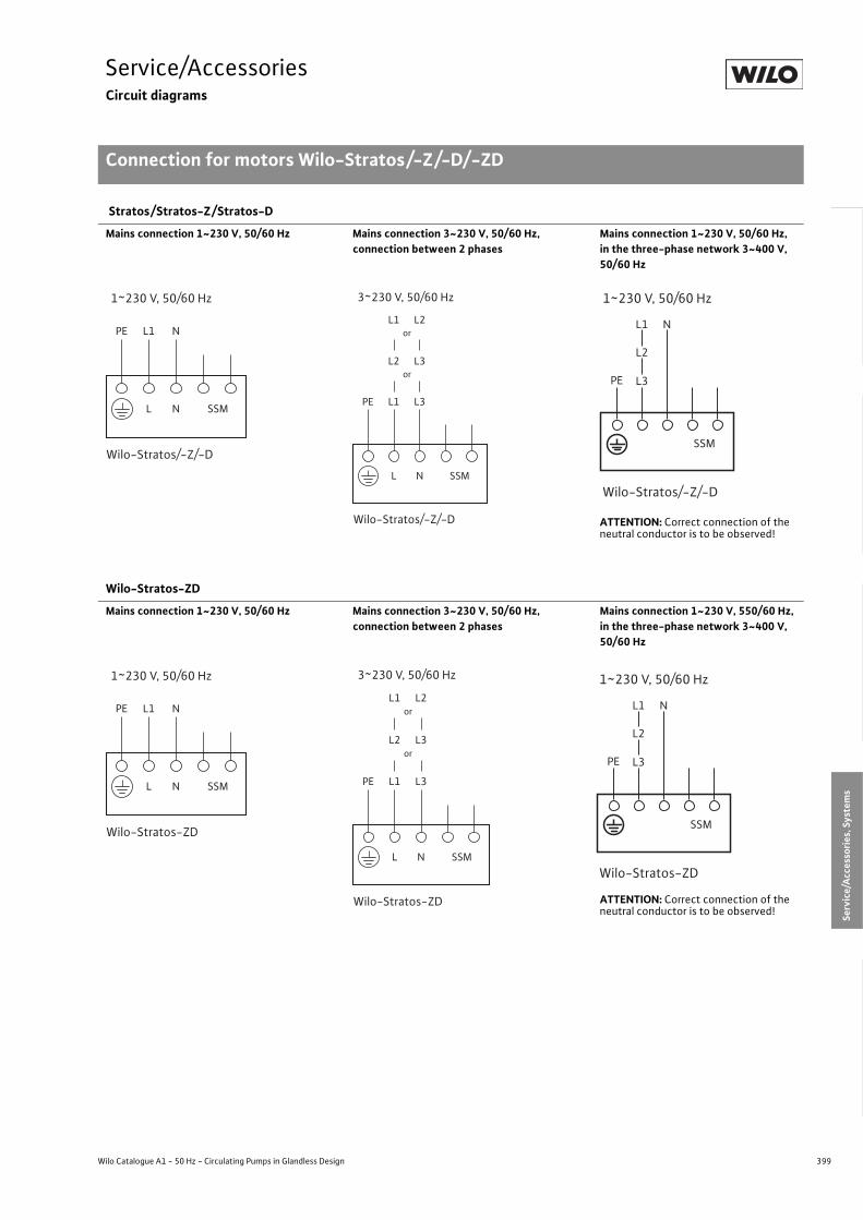
399
Service/AccessoriesCircuit diagrams
Connection for motors Wilo-Stratos/-Z/-D/-ZD
Wilo Catalogue A1 - 50 Hz - Circulating Pumps in Glandless Design
Hea
ting,
Air-
cond
ition
ing,
Co
olin
gSe
cond
ary
Hot W
ater
Circ
ulat
ion
Sola
r The
rmal
, Geo
ther
mal
En
ergy
Sys
tem
sSe
rvic
e/Ac
cess
orie
s, S
yste
ms
Switc
hgea
rs a
nd C
ontr
ol
Dev
ices
Pum
p M
anag
emen
t Sys
tem
s
Stratos/Stratos-Z/Stratos-D
Mains connection 1~230 V, 50/60 Hz Mains connection 3~230 V, 50/60 Hz, connection between 2 phases
Mains connection 1~230 V, 50/60 Hz,in the three-phase network 3~400 V, 50/60 Hz
ATTENTION: Correct connection of the neutral conductor is to be observed!
Wilo-Stratos-ZD
Mains connection 1~230 V, 50/60 Hz Mains connection 3~230 V, 50/60 Hz, connection between 2 phases
Mains connection 1~230 V, 550/60 Hz,in the three-phase network 3~400 V, 50/60 Hz
ATTENTION: Correct connection of the neutral conductor is to be observed!
PE L1 N
L N SSM
Wilo-Stratos/-Z/-D
1~230 V, 50/60 Hz
PE L1 L3
L2 L3or
L1 L2or
L N SSM
Wilo-Stratos/-Z/-D
3~230 V, 50/60 Hz
PE L3
L2
L1 N
SSM
1~230 V, 50/60 Hz
Wilo-Stratos/-Z/-D
PE L1 N
L N SSM
Wilo-Stratos-ZD
1~230 V, 50/60 Hz
PE L1 L3
L2 L3or
L1 L2or
L N SSM
Wilo-Stratos-ZD
3~230 V, 50/60 Hz
PE L3
L2
L1 N
SSM
1~230 V, 50/60 Hz
Wilo-Stratos-ZD

400 Subject to change without prior notice 09/2007 WILO AG
Service/AccessoriesSwitching plugs/servicing apparatus
Wilo – switching plug 3~230 V three-phase current
Retrofittable plug for three-phase current pumps Wilo-TOP-S/-SD/-Z for connecting the pump motor to the existing mains volt-age 3~230 V, 50 Hz.Weight: approximately 30 g.
> FunctionThe simple conversion for connecting the pump to 3~230 V is achieved by replacing the standard-series 400 V speed/voltage plug present in the terminal box of the pump with the 230 V switching plug (acces-sories). This conversion does not permit the con-nection of the pump to 1~230 V. No further wiring work is required.Manual variable speed control with the plug is retained for 3 stages.
Wilo-DKG-II rotation control/service device
Wilo service device with expanded function for electronic, non-contact
- checking of the precise direction of rotation (glanded and glandless pumps) and
- testing for possible pump standstill (stand-ard glandless pumps in single- or three-phase versions).Measurement takes place during operation as a basic principle. It is no longer necessary to switch the pump motor on and off briefly. Device includes 9V battery (commercially available) and testing directions.
> FunctionThree integrated, high-sensitivity sensors measure the stray field of the pump motor when the service device is loaded. Based on the time sequence of the sensor signals, the electronics determines
- the direction of rotation and- the rotation of the pump rotor, and this the
conveyance of the fluid through the pump. Red and yellow LEDs signalise rapidly and clearly disrupted/undisrupted pump opera-tion.
Switching plugs/servicing apparatus
3 230 V 3 400 V
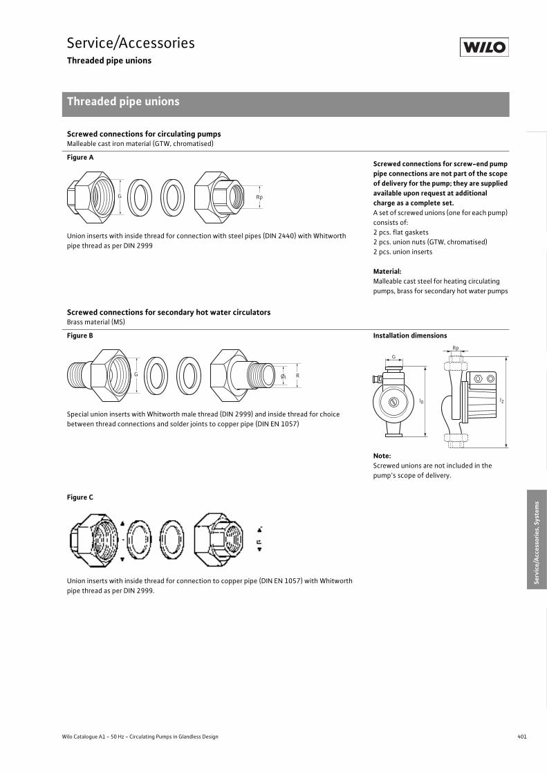
401
Service/AccessoriesThreaded pipe unions
Threaded pipe unions
Wilo Catalogue A1 - 50 Hz - Circulating Pumps in Glandless Design
Hea
ting,
Air-
cond
ition
ing,
Co
olin
gSe
cond
ary
Hot W
ater
Circ
ulat
ion
Sola
r The
rmal
, Geo
ther
mal
En
ergy
Sys
tem
sSe
rvic
e/Ac
cess
orie
s, S
yste
ms
Switc
hgea
rs a
nd C
ontr
ol
Dev
ices
Pum
p M
anag
emen
t Sys
tem
s
Screwed connections for circulating pumpsMalleable cast iron material (GTW, chromatised)
Figure A
Union inserts with inside thread for connection with steel pipes (DIN 2440) with Whitworth pipe thread as per DIN 2999
Screwed connections for screw-end pump pipe connections are not part of the scope of delivery for the pump; they are supplied available upon request at additional charge as a complete set.A set of screwed unions (one for each pump) consists of:2 pcs. flat gaskets2 pcs. union nuts (GTW, chromatised)2 pcs. union inserts
Material:Malleable cast steel for heating circulating pumps, brass for secondary hot water pumps
Screwed connections for secondary hot water circulatorsBrass material (MS)
Figure B
Special union inserts with Whitworth male thread (DIN 2999) and inside thread for choice between thread connections and solder joints to copper pipe (DIN EN 1057)
Installation dimensions
Note:Screwed unions are not included in the pump’s scope of delivery.
Figure C
Union inserts with inside thread for connection to copper pipe (DIN EN 1057) with Whitworth pipe thread as per DIN 2999.
G Rp
G RØi
G
Rp
l0 l2

402 Subject to change without prior notice 09/2007 WILO AG
Service/AccessoriesThreaded pipe unions
Threaded pipe unions
Screwed connections - Pump configuration,dimensions and weights
Dimensions Installation length
Pipe connection size Weight (set) Figure
Variable Rp/R G Øi lo l2DN, steel pipe
DIN 2440DN, copper pipe
DIN EN 1057 – –
Unit – [mm] [mm] – – [kg] –
Screwed connection for circulating pumps:Cast iron material, union insert/union nut GTW chromatisedGTW 1For pumps with pump housing thread G 11/2 Rp 1 G 11/2 –
130
180
184
23425 – 0.46 A
GTW 1 1/4For pumps with pump housing thread G 2 Rp 11/4 G 2 – 180 244 32 – 0.69 A
Screwed connection for secondary hot water circulators:Material brass, union nut GTW chromatisedor brass (for Type MS 3/4)MS 1/2For secondary hot water circulators with housing or fittings male thread G 1
Rp 1/2 G 1 15 140 216 15 Ø 15 0.26 B
MS 3/4For secondary hot water circulators with housing thread G 11/4
Rp 3/4 G 11/4 – 150 195 – R 3/4 0.34 C
MS 1 For secondary hot water circulators with housing thread G 11/2
Rp 1 G 11/2 28 180 274 25 Ø 28 0.72 B
MS 1 1/4For secondary hot water circulators with housing thread G 2
Rp 11/4 G 2 35 180 280 32 Ø 35 1.20 B

403
Service/AccessoriesAdapter fittings
Wilo-(R), Wilo-(RF), Wilo-(F)
Wilo Catalogue A1 - 50 Hz - Circulating Pumps in Glandless Design
Hea
ting,
Air-
cond
ition
ing,
Co
olin
gSe
cond
ary
Hot W
ater
Circ
ulat
ion
Sola
r The
rmal
, Geo
ther
mal
En
ergy
Sys
tem
sSe
rvic
e/Ac
cess
orie
s, S
yste
ms
Switc
hgea
rs a
nd C
ontr
ol
Dev
ices
Pum
p M
anag
emen
t Sys
tem
s
Adapters for length compensation Wilo – (R) Wilo – (R)
New pump Pipe Material Description Weight Part No.
DN C1 C DN I1 I2 – –approxi-mately
[kg]–
DN 25 G 11/2 G 11/2 25 18 20 GG R 24 0.2 110 880 596DN 25 G 11/2 G 11/2 25 28 30 GG R 1 0.3 110 786 891DN 25 G 11/2 G 11/2 25 38 40 GG R 2 0.5 110 626 790DN 25 G 11/2 G 2 32 3 5 Ms R 5 0.1 110 678 298DN 25 G 11/2 G 2 32 13 15 GG R 6 0.3 110 678 493DN 25 G 11/2 G 2 32 18 20 GG R 7 0.4 110 787 094DN 25 G 11/2 G 21/4 40 3 5 Ms R 12 0.1 110 788 294DN 32 G 2 G 2 32 18 20 GG R 8 0.3 110 627 199DN 32 G 2 G 2 32 23 25 GG R 9 0.4 110 627 291DN 32 G 2 G 2 32 28 30 GG R 10 0.5 110 627 394DN 32 G 2 G 2 32 38 40 GG R 14 0.6 110 627 497DN 32 G 2 G 2 32 38 40 Rg R 22 0.8 110 680 092DN 32 G 2 G 2 32 68 70 GG R 11 1.0 110 627 590
ATTENTION: The part no. comprises: 1 adapter and 2 seals
Flanged rings/adapters Wilo-(RF)The Wilo-(RF) adapters are - with a few exceptions - provided for length compensation with PN 6 flanges (RF 4, RF 5 and RF 6 also in PN 16). Pipeline modification is required for length compensation with PN 10/16 flanges.
Flanged rings Wilo – (RF) Wilo – (RF)
New pump Pipe Version Material Description Weightabout [kg]
Part No.
DN G C – I1 I2 – – PN 6/PN 16 PN 6 PN 16
DN 25 G 11/2DN 25
(oval flange) II – – GG RF 7 0.4/- 110 628 790Hole Ø 80 –
DN 25 G 11/2 DN 25 I 25.5 30 GG RF 10 1.0/- 110 851 499 –
DN 25 G 11/2 DN 40 I 15.5 20 GG RF 9 1.4/- 110 679 395 –
DN 25 G 11/2 DN 50 I 25.5 30 GG RF 13 1.9/- 110 679 498 –
DN 32 G 2 DN 32 II – – GG RF 1 1.0/- 110 627 990 –
DN 32 G 2 DN 32 I 2.5 7 GG RF 2 1.4/- 110 680 298 –
DN 32 G 2 DN 32 I 15.5 20 GG RF 3 1.4/- 110 680 596 –
DN 32 G 2 DN 32 I 30.5 35 GG RF 4 2.5/2.7 110 680 699 110 680 791
DN 32 G 2 DN 40 II – – GG RF 0 1.3/- 110 679 796 –
DN 32 G 2DN 40(square flange)
I 5.5 10 GG RF 8 0.9/- 110 680 997Hole Ø 90 –
DN 32 G 2 DN 40 I 5.5 10 GG RF 12 1.6/- 110 851 797 –
DN 32 G 2 DN 50 II – – GG RF 11 1.7/- 110 679 899 –
DN 32 G 2 DN 50 I 15.5 20 GG RF 5 2.8/3.1 110 787 197 110 791 299
DN 32 G 2 DN 50 I 30.5 35 GG RF 6 3.0/3.3 110 787 290 110 791 391
ATTENTION: The part no. comprises: 1 flanged ring, 2 seals and screws
G
l 1
C
l 2l 0
DNNew pump
PipeDN
Union nut
C1
C
l 0
DN
Newpump
C1
l 1
C
l 2l 0
DN
Newpump
Pipework
Pipework
Version II
Version I

404 Subject to change without prior notice 09/2007 WILO AG
Service/AccessoriesAdapter fittings
Wilo-(R), Wilo-(RF), Wilo-(F)
Intermediate flange pieces/adapters Wilo-(F)The Wilo-(F) adapters are - with a few exceptions - provided for length compensation with PN 6 or PN 16 flanges. Onsite pipe alteration is required if adapters are not available.The washers included in the scope of delivery must be used with pumps that have combination flanges. F1-MS single-ended flanged nipple made of CW 612 N bronze/brass authorised for secondary hot water circulation systems.
Intermediate flange piece for length compensation Wilo – (F) Wilo – (F)
New pump Pipe Material Description Weight about [kg]
Part No.
DN C I1 I2 Ød – – PN 6/PN 16 PN 6 PN 16
DN 40 DN 40 13 15 91 GG F 0 0.8/1.1 110 842 497
110 842 590
DN 40 DN 40 28 30 91 GG F 1 1.4/1.7 110 586 593
110 586 696
DN 40 DN 40 28 30 90 MS F1-MS 1.4/1.9 2 060 865 2 060 920
DN 40 DN 40 48 50 106 GG F 26 2.1/2.4 110 851 098
110 851 190
DN 50 DN 50 8 10 106 GG F 2 0.7/0.9 110 787 690
110 791 494
DN 50 DN 50 18 20 106 GG F 3 1.1/1.4 110 623 098
110 623 190
DN 50 DN 50 28 30 106 GG F 4 1.7/2.0 110 681 292
110 681 395
DN 50 DN 50 33 35 126 GG F 5 1.9/2.2 110 623 293
110 623 396
DN 65 DN 65 8 10 126 GG F 9 0.8/1.1 110 787 896
110 791 690
DN 65 DN 65 18 20 126 GG F 10 1.5/1.8 110 624 092
110 624 195
DN 65 DN 65 28 30 141 GG F 11 2.2/2.5 110 624 298
110 624 390
DN 65 DN 65 38 40 141 GG F 28 2.8/3.1 110 681 498
110 681 590
DN 65 DN 65 43 45 141 GG F 29 3.1/3.4 110 681 693
110 681 796
DN 80 DN 80 8 10 91 GG F 16 0.9/– 110 788 099 -
DN 80 DN 80 18 20 126 GG F 17 2.1/– 110 625 097 -
DN 80 DN 80 23 25 126 GG F 30 2.4/3.3 110 681 899
110 681 991
DN 80 DN 80 38 40 141 GG F 18 3.7/– 110 625 292 -
DN 100 DN 100 33 35 161 GG F 34 3.9/– 110 851 293 -
DN 100 DN 100 53 55 161 GG F 35 5.7/– 110 862 592 -
ATTENTION: The part no. comprises: 1 adapter, 2 seals and screws
l 1
C
l 2l 0
DN
Newpump
Pipe-work DN
l 1
C
l 2l 0
DN
Newpump
Pipe-work DN
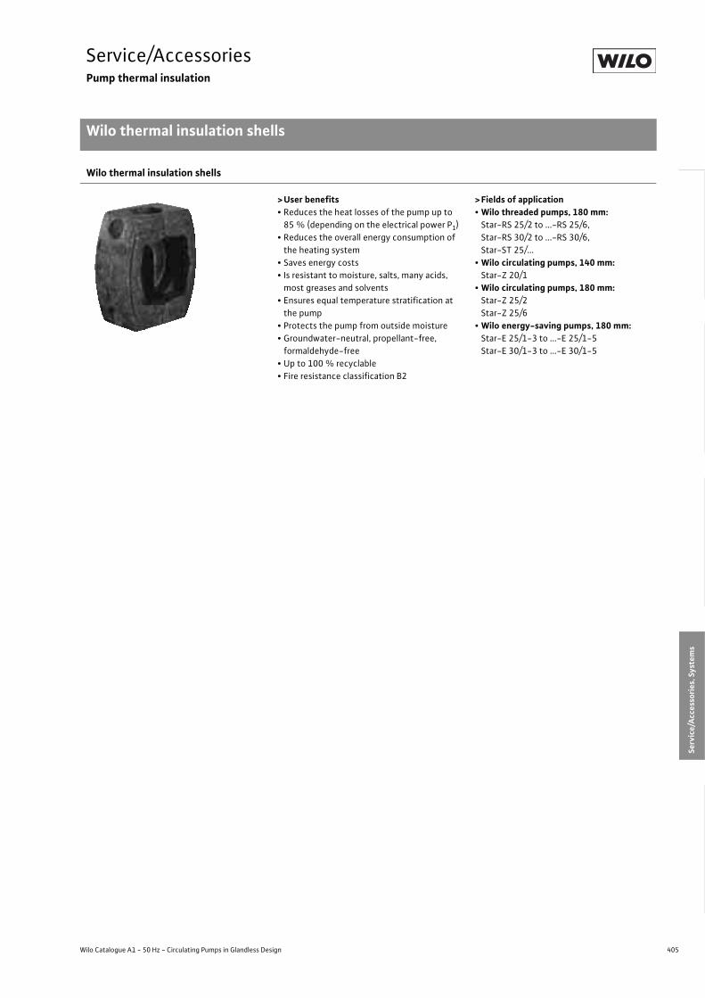
405
Service/AccessoriesPump thermal insulation
Wilo thermal insulation shells
Wilo Catalogue A1 - 50 Hz - Circulating Pumps in Glandless Design
Hea
ting,
Air-
cond
ition
ing,
Co
olin
gSe
cond
ary
Hot W
ater
Circ
ulat
ion
Sola
r The
rmal
, Geo
ther
mal
En
ergy
Sys
tem
sSe
rvic
e/Ac
cess
orie
s, S
yste
ms
Switc
hgea
rs a
nd C
ontr
ol
Dev
ices
Pum
p M
anag
emen
t Sys
tem
s
Wilo thermal insulation shells
>User benefits• Reduces the heat losses of the pump up to
85 % (depending on the electrical power P1)• Reduces the overall energy consumption of
the heating system• Saves energy costs• Is resistant to moisture, salts, many acids,
most greases and solvents• Ensures equal temperature stratification at
the pump• Protects the pump from outside moisture• Groundwater-neutral, propellant-free,
formaldehyde-free• Up to 100 % recyclable• Fire resistance classification B2
>Fields of application• Wilo threaded pumps, 180 mm:
Star-RS 25/2 to ...-RS 25/6,Star-RS 30/2 to ...-RS 30/6,Star-ST 25/...
• Wilo circulating pumps, 140 mm:Star-Z 20/1
• Wilo circulating pumps, 180 mm:Star-Z 25/2Star-Z 25/6
• Wilo energy-saving pumps, 180 mm:Star-E 25/1-3 to ...-E 25/1-5Star-E 30/1-3 to ...-E 30/1-5
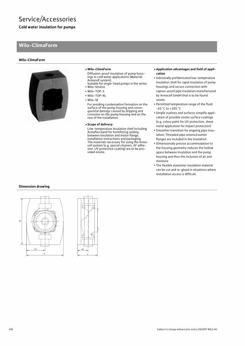
406 Subject to change without prior notice 09/2007 WILO AG
Service/AccessoriesCold water insulation for pumps
Wilo-ClimaForm
Wilo-ClimaForm
> Wilo-ClimaFormDiffusion-proof insulation of pump hous-ings in cold water applications (Material: Armacell system). Suitable for single-head pumps in the series:
• Wilo-Stratos• Wilo-TOP-S• Wilo-TOP-RL• Wilo-SE
For avoiding condensation formation on the surface of the pump housing and conse-quential damage caused by dripping and corrosion on the pump housing and on the rest of the installation.
> Scope of delivery:Low-temperature insulation shell including Armaflex band for formfitting sealing between insulation and motor flange, installation instructions and packaging. The materials necessary for using the Arma-cell system (e.g. special cleaners, AF adhe-sive, UV protective coating) are to be pro-vided onsite.
> Application advantages and field of appli-cation
• Industrially prefabricated low-temperature insulation shell for rapid insulation of pump housings and secure connection with vapour-proof pipe insulation manufactured by Armacell GmbH that is to be found onsite.
• Permitted temperature range of the fluid: -10 °C to +105 °C
• Simple outlines and surfaces simplify appli-cation of possible onsite surface coatings (e.g. colour paint for UV protection, sheet metal application for impact protection)
• Smoother transition for ongoing pipe insu-lation: Threaded pipe unions/counter flanges are included in the insulation
• Dimensionally precise accommodation to the housing geometry reduces the hollow space between insulation and the pump housing and thus the inclusion of air and moisture
• The flexible elastomer insulation material can be cut and re-glued in situations where installation access is difficult.
Dimension drawing
b1
l0
b
a1
a

407
Service/AccessoriesCold water insulation for pumps
Wilo-ClimaForm
Wilo Catalogue A1 - 50 Hz - Circulating Pumps in Glandless Design
Hea
ting,
Air-
cond
ition
ing,
Co
olin
gSe
cond
ary
Hot W
ater
Circ
ulat
ion
Sola
r The
rmal
, Geo
ther
mal
En
ergy
Sys
tem
sSe
rvic
e/Ac
cess
orie
s, S
yste
ms
Switc
hgea
rs a
nd C
ontr
ol
Dev
ices
Pum
p M
anag
emen
t Sys
tem
s
Dimensions
Wilo-... Dimensions depending on pump typel0 a a1 b b1
[mm]Stratos 25/1-6 240 137 68 150 75Stratos 25/1-8 240 137 68 150 75Stratos 30/1-6 240 137 68 150 75Stratos 30/1-8 240 137 68 150 75Stratos 30/1-12 240 145 75 162 81Stratos 32/1-12 350 192 97 225 112.5Stratos 40/1-4 350 199 101 240 120Stratos 40/1-8 350 205 103 240 120Stratos 40/1-12 380 207 107 240 120Stratos 50/1-8 380 219 112 260 130Stratos 50/1-9 420 225 115 270 135Stratos 50/1-12 420 225 115 270 135Stratos 65/1-9 420 239 121 280 140Stratos 65/1-12 490 249 132 290 145Stratos 80/1-12 520 262 133 320 160Stratos 100/1-12 520 280 145 350 175TOP-RL 25/7.5 240 117 62 144 72TOP-RL 30/4 240 133 76 170 85TOP-RL 30/6.5 240 133 76 170 85TOP-RL 30/7.5 240 117 62 144 72SE 110-N 240 133 76 170 85SE 125-N 240 117 62 144 72TOP-S 30/4 240 133 76 170 85TOP-S 25/5 240 117 62 144 72TOP-S 30/5 240 117 62 144 72TOP-S 25/7 240 110 62 176 88TOP-S 25/10 1) 240 121 68 188 94TOP-S 25/13 240 87 55 180 90TOP-S 30/7 240 117 68 176 88TOP-S 30/10 1) 240 121 68 188 94TOP-S 40/4 350 207 108 240 120TOP-S 40/7 380 211 111 240 120TOP-S 40/10 380 213 109 240 120TOP-S 40/15 1) 380 210 106 260 130TOP-S 50/4 380 225 117 260 130TOP-S 50/7 420 226 115 270 135TOP-S 50/10 420 226 119 270 135TOP-S 50/15 1) 490 250 202 266 133
1) Because of the complex geometry of the pump bodies, the insulation layer thickness specification of 19 mm may not be present in certain areas with this Clima-Form. In the event of the simultaneous occurrence of extreme operating conditions involving - low fluid temperature (< 0 °C) and- high ambient temperature (> 22 °C) and- high atmospheric humidity (> 72 %),limited local condensation formation may appear on the surface of the ClimaForm. This represents no impairment of the protective function of the pump. The same applies in the event that the ClimaForm insulation layer is squeezed to a lesser thickness.

408 Subject to change without prior notice 09/2007 WILO AG
Service/AccessoriesCold water insulation for pumps
Wilo-ClimaForm
TOP-S 65/7 420 240 125 270 135TOP-S 65/10 490 247 131 290 145TOP-S 65/13 490 247 131 290 145TOP-S 65/15 490 247 131 290 145TOP-S 80/7 (3~) 500 252 130 320 160TOP-S 80/7 (1~) 500 246 125 320 160TOP-S 80/10 500 246 125 320 160TOP-S 100/10 520 272 136 350 175
Dimensions
Wilo-... Dimensions depending on pump typel0 a a1 b b1
[mm]

409
SystemsContents
Wilo Catalogue A1 - 50 Hz - Circulating Pumps in Glandless Design
Hea
ting,
Air-
cond
ition
ing,
Co
olin
gSe
cond
ary
Hot W
ater
Circ
ulat
ion
Sola
r The
rmal
, Geo
ther
mal
En
ergy
Sys
tem
sSe
rvic
e/Ac
cess
orie
s, S
yste
ms
Switc
hgea
rs a
nd C
ontr
ol
Dev
ices
Pum
p M
anag
emen
t Sys
tem
s
Systems
Series overview 410
Package heat exchanger assembly Wilo-Safe-WS 410
Series description 411
Technical data 413
Condensate lifting unit Wilo-DrainLift Con 414
Series description 414
Technical data, pump curve, dimension drawing 415
Pump curve, dimension drawing 416
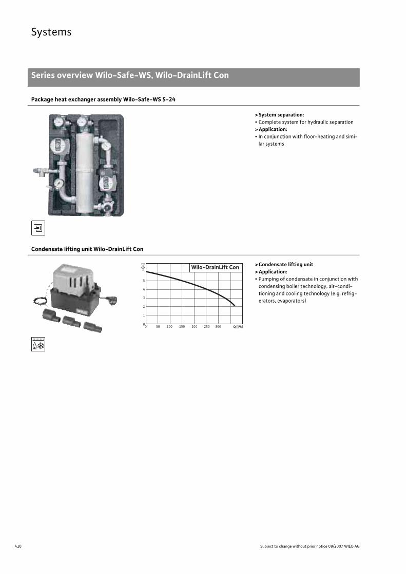
410 Subject to change without prior notice 09/2007 WILO AG
Systems
Series overview Wilo-Safe-WS, Wilo-DrainLift Con
Package heat exchanger assembly Wilo-Safe-WS 5-24
> System separation:• Complete system for hydraulic separation> Application:• In conjunction with floor-heating and simi-
lar systems
Condensate lifting unit Wilo-DrainLift Con
> Condensate lifting unit> Application:• Pumping of condensate in conjunction with
condensing boiler technology, air-condi-tioning and cooling technology (e.g. refrig-erators, evaporators)
0 50 100 150 200 250 3000
1
2
3
4
5
H[m
]
Wilo-DrainLift Con
Q [l/h]

411
SystemsPackage heat exchanger assembly
Series description Wilo-Safe-WS
Wilo Catalogue A1 - 50 Hz - Circulating Pumps in Glandless Design
Hea
ting,
Air-
cond
ition
ing,
Co
olin
gSe
cond
ary
Hot W
ater
Circ
ulat
ion
Sola
r The
rmal
, Geo
ther
mal
En
ergy
Sys
tem
sSe
rvic
e/Ac
cess
orie
s, S
yste
ms
Switc
hgea
rs a
nd C
ontr
ol
Dev
ices
Pum
p M
anag
emen
t Sys
tem
s
Wilo-Safe WS 5-24
> Wilo-Safe WS 5-24 compl. consisting of:
- Wilo-Safe fundamental unit WSG 5-24,- Wilo-Safe connector set WSA 5-24,- Wilo-Safe mixer WSM 5-24> Wilo-Safe WS 5-24 E compl.
as for WS 5-24 complete, although with- Energy-saving pump for floor area, Type Wilo-Star-ZE 25/1-5- Adjustable pump control modes �p-constant or �p-variable
Wilo-Safe fundamental unit WSG 5-24
> Wilo-Safe fundamental unit WSG 5-24consisting of:
- Floor-area pump Star-Z 25/6 with red brass housing, 1.8 m electric cable- Special heat exchanger WT 5-24 Ms/Cu- Secondary pipe assembly with safety valve 2.5 bar, fill/drain cock
2 pieces multipurpose fittings with ball block and integrated ther-mometer 0 - 120 °C including immersion well (for additional temper-ature sensor), possibility of connecting an expansion tank
- Pressure gauge 4 bar- 2 thermal insulation shells made of environmentally-friendly EPP
with pre-stamped cut-out provisions for right-hand installation, including wall brackets and fixing materials
Performance parameters for WS 5-24 complete
Primary circuit Secondary circuitThermal output up to maximum Volume flow Feed
temperatureReturn
temperature Volume flow Feed temperature
Return temperature
[kW] [m3/h] [°C] [°C] [m3/h] [°C] [°C]
Conventional boiler 26 1.1 80 60 2.2 45 35
Low-temperature boiler
22 0.95 70 50 1.9 40 30
Condensing boiler 15 1.3 55 45 1.3 40 30
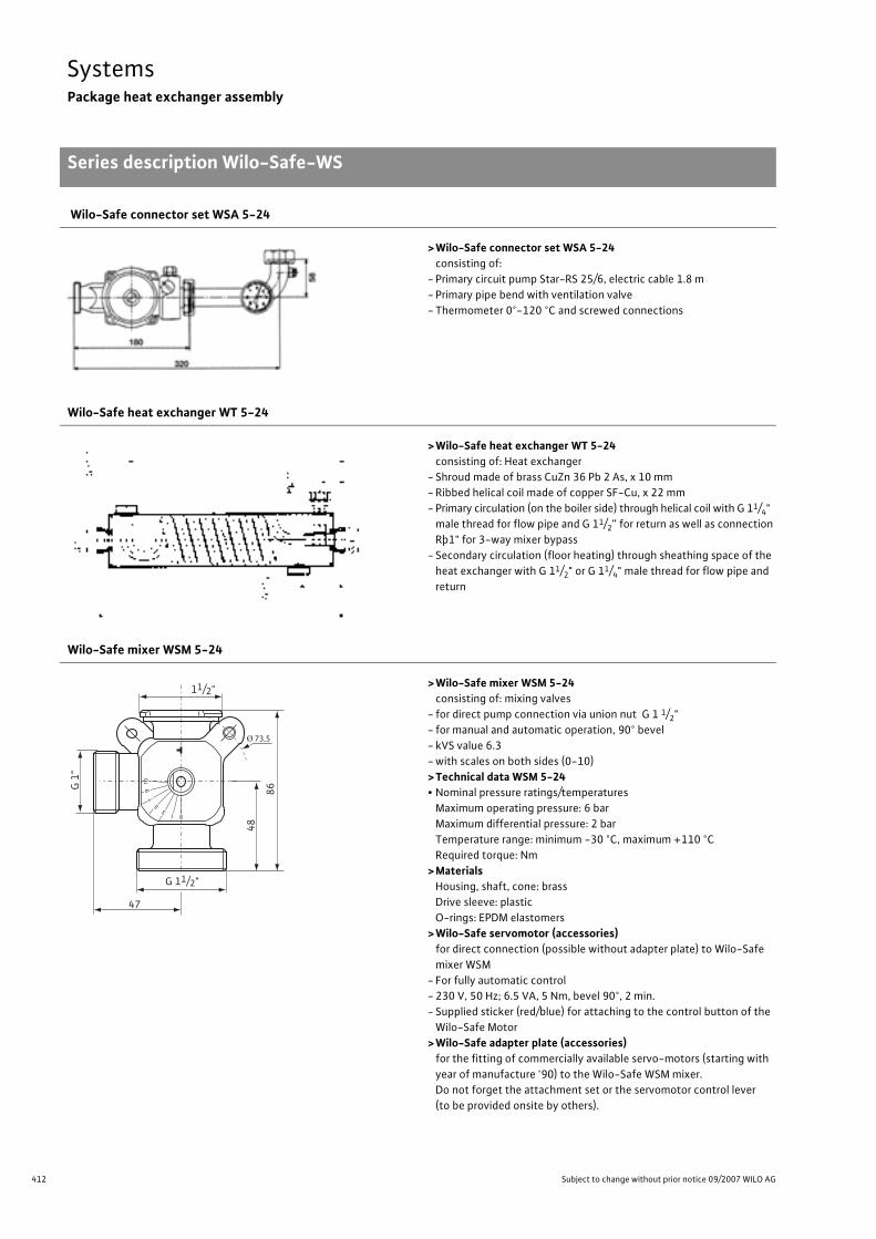
412 Subject to change without prior notice 09/2007 WILO AG
SystemsPackage heat exchanger assembly
Series description Wilo-Safe-WS
Wilo-Safe connector set WSA 5-24
>Wilo-Safe connector set WSA 5-24consisting of:
- Primary circuit pump Star-RS 25/6, electric cable 1.8 m- Primary pipe bend with ventilation valve- Thermometer 0°-120 °C and screwed connections
Wilo-Safe heat exchanger WT 5-24
>Wilo-Safe heat exchanger WT 5-24consisting of: Heat exchanger
- Shroud made of brass CuZn 36 Pb 2 As, x 10 mm- Ribbed helical coil made of copper SF-Cu, x 22 mm- Primary circulation (on the boiler side) through helical coil with G 11/4"
male thread for flow pipe and G 11/2” for return as well as connection Rþ1" for 3-way mixer bypass
- Secondary circulation (floor heating) through sheathing space of the heat exchanger with G 11/2" or G 11/4" male thread for flow pipe and return
Wilo-Safe mixer WSM 5-24
>Wilo-Safe mixer WSM 5-24consisting of: mixing valves
- for direct pump connection via union nut G 1 1/2" - for manual and automatic operation, 90° bevel- kVS value 6.3- with scales on both sides (0-10)>Technical data WSM 5-24• Nominal pressure ratings/temperatures
Maximum operating pressure: 6 bar Maximum differential pressure: 2 barTemperature range: minimum -30 °C, maximum +110 °CRequired torque: Nm
>MaterialsHousing, shaft, cone: brassDrive sleeve: plasticO-rings: EPDM elastomers
>Wilo-Safe servomotor (accessories)for direct connection (possible without adapter plate) to Wilo-Safe mixer WSM
- For fully automatic control- 230 V, 50 Hz; 6.5 VA, 5 Nm, bevel 90°, 2 min.- Supplied sticker (red/blue) for attaching to the control button of the
Wilo-Safe Motor>Wilo-Safe adapter plate (accessories)
for the fitting of commercially available servo-motors (starting with year of manufacture '90) to the Wilo-Safe WSM mixer.Do not forget the attachment set or the servomotor control lever (to be provided onsite by others).
11/2"
G 11/2"
47
86
Ø 73,5
48
G 1
"

413
SystemsPackage heat exchanger assembly
Technical data Wilo-Safe WS
Wilo Catalogue A1 - 50 Hz - Circulating Pumps in Glandless Design
Hea
ting,
Air-
cond
ition
ing,
Co
olin
gSe
cond
ary
Hot W
ater
Circ
ulat
ion
Sola
r The
rmal
, Geo
ther
mal
En
ergy
Sys
tem
sSe
rvic
e/Ac
cess
orie
s, S
yste
ms
Switc
hgea
rs a
nd C
ontr
ol
Dev
ices
Pum
p M
anag
emen
t Sys
tem
s
Wilo-Safe WS 5-24
Approved fluids(other fluids on request)
Heating water (as per VDI 2035) •Water/glycol mixtures maximum 50%/50% –
Performance
Maximum delivery head [m] –
Maximum flow volume [m3/h] –
Speed range [1/min] –
Permitted field of application
Temperature rangeat maximum 40 °C ambient temperature [°C] 20 - 90
Nominal pressure, maximum [bar] 6
Connections
Nominal connection width Page dimension drawings
Electrical connection
Mains connection [V/Hz] 230/50
Motor/electronics
Emitted interference EN 61000-6-3
Immunity to interference EN 61000-6-2
Radio interference level –
Protection class –
Insulation class –
Materials(special version available at additional charge)
Pump housing –
Impeller –
Shaft –
Bearing –
Dimensions/weights
Gross volume [l] –
Weight [kg] 14.6
• = available, – = not available

414 Subject to change without prior notice 09/2007 WILO AG
SystemsLifting unit for condensates
Series description Wilo-DrainLift Con
Wilo-DrainLift ConAutomatic lifting unit for condensates with feed adapters (accessory)
Type keyExample: Wilo-DrainLift ConCon Condensate
Product advantages• Low-noise operation (� 43 dB[A])• 2 intake openings• Standard-series alarm contact (normally closed contact/normally
open contact)• Easy to install• Motor unit can be reversed by 180°• Variable feed lines/drains• Suitable for condensates with a pH value � 2.4
ApplicationThe condensate lifting unit must be used if disposal is not possible via natural gravity flow, or if the installation location is below the back-flow level. It has been designed for installation in condensing boilers that generate aggressive condensate according to the specifications of worksheet A 251 as distributed by the ATV (German Association for Water, Wastewater and Waste). Because of the materials used in the manufacture of the plant, condensate with a pH value of up to 2.4 can be conveyed without any problems. For oil-fired or gas-fired boilers with an output > 200 kW, the lifting unit must be installed downline of a neutralisation system. The condensate lifting unit can also be used in the air-conditioning and cooling systems where con-densate is produced, for example refrigerators and freezers, evapora-tors, and refrigerated display cases.
The plant can be installed in free-standing form or vertically wall-mounted with two fastening holes. The positioning of the motor unit on the tank is reversible, allowing a variable inlet and outlet.
Construction2 inlets in the lid (19 mm or 2 mm). Hose connection on discharge end, DN 10 mm with built-in check valve. Motor unit can be reversed by 180°.
Scope of deliveryLifting unit ready for connection with standard-series alarm contact (normally closed contact/normally open contact) for connection to condensing boilers or to alarm switchgears. Including hose connection with integrated non-return valve, 5 m hose for discharge side, 1 m alarm cable and 2 m network cable with shockproof plug in addition to wall fixation material and installation and operating instructions.
Accessories- Intake adapter Ø 24 to 25 mm, Ø 24 to 30 mm, Ø 24 to 40 mm- Pressure hose 25 m length

415
SystemsLifting unit for condensates
Technical data Wilo-DrainLift Con
Wilo Catalogue A1 - 50 Hz - Circulating Pumps in Glandless Design
Hea
ting,
Air-
cond
ition
ing,
Co
olin
gSe
cond
ary
Hot W
ater
Circ
ulat
ion
Sola
r The
rmal
, Geo
ther
mal
En
ergy
Sys
tem
sSe
rvic
e/Ac
cess
orie
s, S
yste
ms
Switc
hgea
rs a
nd C
ontr
ol
Dev
ices
Pum
p M
anag
emen
t Sys
tem
s
Wilo-DrainLift Con
Approved fluids
Charged condensate (pH � 2.4) •
Electrical connection
Mains connection [V] 1~230
Connected load P1 [kW] 0.08
Nominal current [A] 0.8
Mains frequency [Hz] 50
Cable length from plant to switchgear/plug [m] 2
Permitted field of application
Operating mode S3 - 15%
Fluid temperature, maximum [°C] 80
Connections
Delivery connection [mm] 12
Intake connection [mm] 19/24
Motor
Protection class IP 20
Dimensions/weights
Gross volume [l] 1.5
Weight [kg] 2
• = available or authorised, – = not available or not authorised

416 Subject to change without prior notice 09/2007 WILO AG
SystemsLifting unit for condensates
Pump curve, dimension drawing Wilo-DrainLift Con
Pump curve
Dimension drawing
[l/h]0 50 100 150 200 250 300 350
H
0
2
4
3
5
6
1
Q
Wilo-DrainLift Con [m]
21
Ø 12
195
169,
513
0
82,5
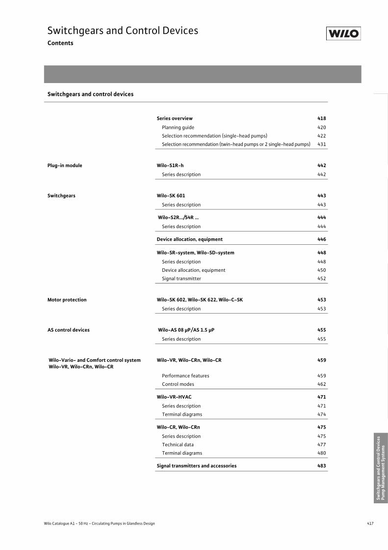
417
Switchgears and Control DevicesContents
Wilo Catalogue A1 - 50 Hz - Circulating Pumps in Glandless Design
Hea
ting,
Air-
cond
ition
ing,
Co
olin
gSe
cond
ary
Hot W
ater
Circ
ulat
ion
Sola
r The
rmal
, Geo
ther
mal
En
ergy
Sys
tem
sSe
rvic
e/Ac
cess
orie
s, S
yste
ms
Switc
hgea
rs a
nd C
ontr
ol D
evic
esPu
mp
Man
agem
ent S
yste
ms
Switchgears and control devices
Series overview 418
Planning guide 420
Selection recommendation (single-head pumps) 422
Selection recommendation (twin-head pumps or 2 single-head pumps) 431
Plug-in module Wilo-S1R-h 442
Series description 442
Switchgears Wilo-SK 601 443
Series description 443
Wilo-S2R.../S4R … 444
Series description 444
Device allocation, equipment 446
Wilo-SR-system, Wilo-SD-system 448
Series description 448
Device allocation, equipment 450
Signal transmitter 452
Motor protection Wilo-SK 602, Wilo-SK 622, Wilo-C-SK 453
Series description 453
AS control devices Wilo-AS 08 �P/AS 1.5 �P 455
Series description 455
Wilo-Vario- and Comfort control system Wilo-VR, Wilo-CRn, Wilo-CR
Wilo-VR, Wilo-CRn, Wilo-CR 459
Performance features 459
Control modes 462
Wilo-VR-HVAC 471
Series description 471
Terminal diagrams 474
Wilo-CR, Wilo-CRn 475
Series description 475
Technical data 477
Terminal diagrams 480
Signal transmitters and accessories 483

418 Subject to change without prior notice 09/2007 WILO AG
Switchgears and Control DevicesPlug-in modules, switchgears, motor protection
Series overview
Plug-in modulesSeries: Wilo-S1R-h
> Time switching for secondary hot water circulators• Retrofittable plug-in module for time-sensitive ON/OFF control in secondary hot water circu-
lation systems
SwitchgearsSeries: Wilo-SK 601
> Time switch unit• Switchgear for automatic time-sensitive On/Off control• For single-head pumps driven by single-phase or three-phase AC motors• Maximum switching capacity 10 A
Series: Wilo-SR-system and Wilo-SD-system
> Twin-head pump switching• Switchgear for dual pump management of glandless and glanded pumps• For single-phase or three-phase AC motors• 10 A maximum switching capacity for each pump• Time- or fault-sensitive pump duty switchover• Time- or load-sensitive peak-load cut-in• Including full motor protection apparatus
Motor protectionSeries: Wilo-SK 602/SK 622, Wilo-C-SK
> Full motor protection relays• Full motor protection relays for pumps with thermal winding contacts (WSK)• Wall-mounted device for pumps with single-phase and three-phase AC motors• Additional potential-free run and fault signals (only Wilo-SK 622)• Retrofittable plug-in module for 4-stage glandless pump with three-phase motor
(only Wilo-C-SK)
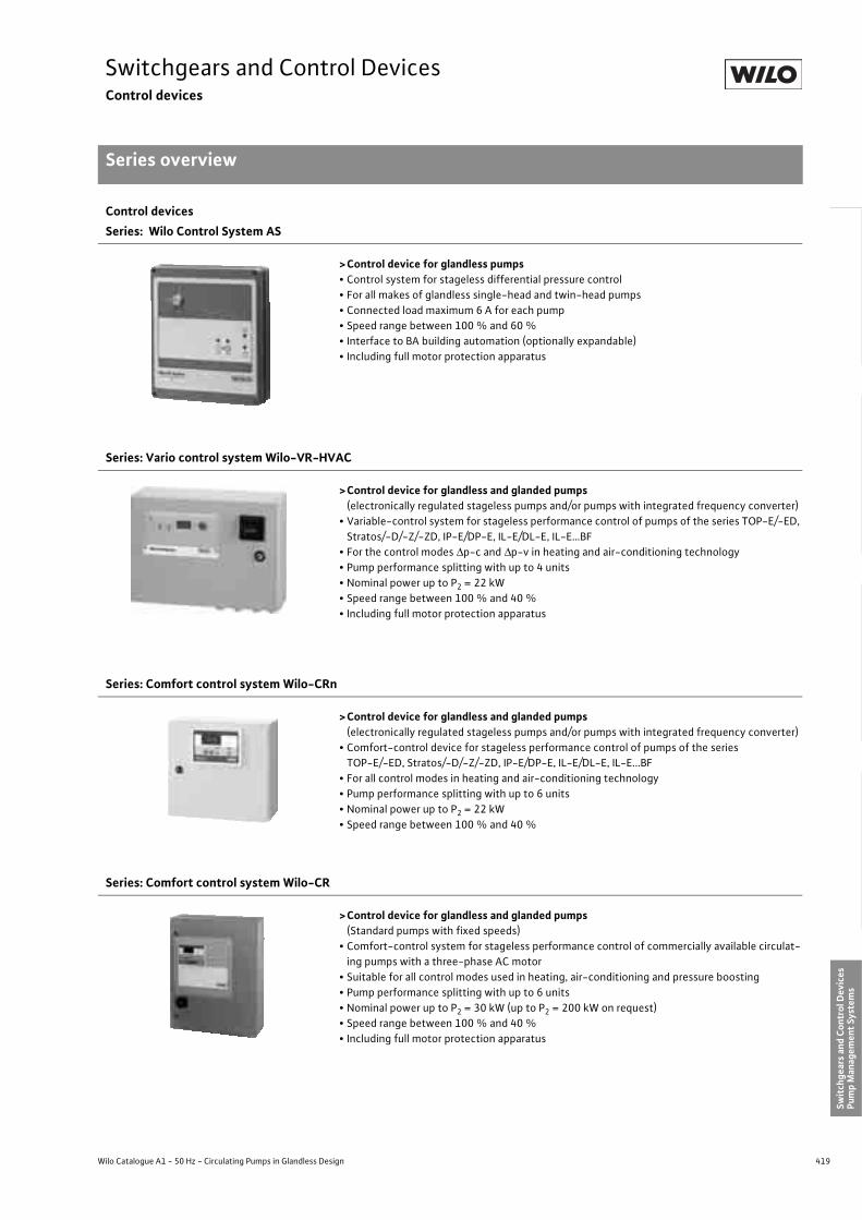
419
Switchgears and Control DevicesControl devices
Series overview
Wilo Catalogue A1 - 50 Hz - Circulating Pumps in Glandless Design
Hea
ting,
Air-
cond
ition
ing,
Co
olin
gSe
cond
ary
Hot W
ater
Circ
ulat
ion
Sola
r The
rmal
, Geo
ther
mal
En
ergy
Sys
tem
sSe
rvic
e/Ac
cess
orie
s, S
yste
ms
Switc
hgea
rs a
nd C
ontr
ol D
evic
esPu
mp
Man
agem
ent S
yste
ms
Control devicesSeries: Wilo Control System AS
>Control device for glandless pumps• Control system for stageless differential pressure control• For all makes of glandless single-head and twin-head pumps• Connected load maximum 6 A for each pump• Speed range between 100 % and 60 %• Interface to BA building automation (optionally expandable)• Including full motor protection apparatus
Series: Vario control system Wilo-VR-HVAC
>Control device for glandless and glanded pumps(electronically regulated stageless pumps and/or pumps with integrated frequency converter)
• Variable-control system for stageless performance control of pumps of the series TOP-E/-ED, Stratos/-D/-Z/-ZD, IP-E/DP-E, IL-E/DL-E, IL-E…BF
• For the control modes �p-c and �p-v in heating and air-conditioning technology• Pump performance splitting with up to 4 units• Nominal power up to P2 = 22 kW• Speed range between 100 % and 40 %• Including full motor protection apparatus
Series: Comfort control system Wilo-CRn
>Control device for glandless and glanded pumps(electronically regulated stageless pumps and/or pumps with integrated frequency converter)
• Comfort-control device for stageless performance control of pumps of the series TOP-E/-ED, Stratos/-D/-Z/-ZD, IP-E/DP-E, IL-E/DL-E, IL-E...BF
• For all control modes in heating and air-conditioning technology• Pump performance splitting with up to 6 units• Nominal power up to P2 = 22 kW• Speed range between 100 % and 40 %
Series: Comfort control system Wilo-CR
>Control device for glandless and glanded pumps (Standard pumps with fixed speeds)
• Comfort-control system for stageless performance control of commercially available circulat-ing pumps with a three-phase AC motor
• Suitable for all control modes used in heating, air-conditioning and pressure boosting• Pump performance splitting with up to 6 units• Nominal power up to P2 = 30 kW (up to P2 = 200 kW on request)• Speed range between 100 % and 40 %• Including full motor protection apparatus

420 Subject to change without prior notice 09/2007 WILO AG
Switchgears and Control DevicesPlanning guide
Pump performance control
Pump performance controlLoad-conditioned excess pump performanceCirculating pumps for central heating and air-conditioning as well as the hydraulic pipe system must by necessity be designed to be capa-ble to meet the maximum design load at minimum outside tempera-tures.These maximum load conditions do however exist only on a very few days during the course of the heating/cooling season. A typical load factor curve for a central heating system is shown on the graph.Centralised and decentralised control systems intervene continu-ously in the installation hydraulics in order to make adjustments to accommodate the actual load situation; in most cases, they cause a reduction of the flow volume while at the same time increasing the pump delivery head. Such operating states are non-economical for pump operations, because lower delivery heads would in fact be suf-ficient, particularly for low flow volumes; in addition, the noise levels that would result must be avoided under all circumstances.
Fig.: Typical heating load factor graph for a central heating system: about 5500 h
The Wilo solution: load-sensitive power adjustment
Type of control/control mode Pump model/pump type
Signal/controlled variable
Controlsystem
Integrated stageless differential-pressure control Stratos/Stratos-ZStar-E/Star-ZE
TOP-EIP-E/IL-E
�p Standard equipment
Time-sensitive ON/OFF control TOP-Z t SK 601– Single-head pumps Star-Z t S1R-h/SK 601
RS/RP t SK 601Variable speed control– Single-head pumps P �p, +T, �T, t S2R 2.5/S4R 2.5
– Twin-head pumps DOP �p, +T, �T, t S4R 2.5 DDual control Stratos/Stratos-Z/
Stratos-D/Stratos-ZD �p, t Stratos IF-Module
TOP-E/-ED �p, t IF-ModuleIP-E/DP-E �p, tIL-E/DL-E �p, t IF-Module
Glandless and glanded �p, +T, �T, t S2R 3D/SDStageless performance control– Single-head and twin-head pumps
RP/RS/RSDP
DOP�p, t AS system
– Individual- and multi-pump systems Glandless and glanded �p, ±T, �T, t, DDC CR systemMotor protection Glandless pumps – SK 602/SK 622/C-SKBuilding automation – – Wilo-Control
�p = differential pressure ±T = feed/return temperature �T = differential temperature t = time
Operating range Heating days Lo
ad fa
ctor
�

421
Switchgears and Control DevicesPlanning guide
Pump performance control
Wilo Catalogue A1 - 50 Hz - Circulating Pumps in Glandless Design
Hea
ting,
Air-
cond
ition
ing,
Co
olin
gSe
cond
ary
Hot W
ater
Circ
ulat
ion
Sola
r The
rmal
, Geo
ther
mal
En
ergy
Sys
tem
sSe
rvic
e/Ac
cess
orie
s, S
yste
ms
Switc
hgea
rs a
nd C
ontr
ol D
evic
esPu
mp
Man
agem
ent S
yste
ms
Need for controlThree main criteria, in line with the steady development of mechani-cal equipment for building services and the growing sensibility towards energy consumption, have led to the increased considera-tion of controls for utilisation in conjunction with heating pumps.
1. Function optimisationAdjusting the pump capacity/heat flow to actual load demand, par-ticularly to stabilise hydraulic conditions and to reduce circulating losses.
2. Economic efficiencyLowering of electricity consumption and operating costs, particularly in partial load or low load operation (thus during more than 80 % of the operating time).
3. Comfort and convenienceAvoiding system noise, in particular flow noise and noise in the ther-mostatic valves that are due to excessive flow and thermostatic radi-ator valves (TRVs).
Power savings in relation to reducing CO2 emissions are in conjunc-tion with environmental-protection considerations playing an ever more important role. It is widely known that generating power from fossil fuels produces significant levels of CO2 emissions. The amount that has been established in Germany as a calculation variable for determining the amount of CO2 released during the generation of one kWh of electricity is approximately 0.56 kg.The decisive factor for concentrating studies on pumps in particular is their proportionally high share of power consumption within the energy balance of buildings.The causes for this are the high levels of operating hours as well as the familiar phenomenon of over-dimensioning heating pumps at the planning stage, factors which considerably add to the energy bal-ance. Over-dimensioning by a factor of 2 to 5 times is the usual standard.
Pump performance control through speed variationOf the many procedures developed and tried in the past to automati-cally control pump performance to actual load demands, among them mechanical/hydraulic processes (bypass/throttling control), the method of variable speed control has proved to be the most lasting. Particularly the high efficiency and the easy handling have ensured its dominance as the vital performance parameters – volume flow, head and input power – directly relate to changes of speed.
n1/n2 = Q1/Q2 (n1/n2)2 = H1/H2 (n1/n2)3 = P1/P2
Thus, for example, when motor speed is doubled, the flow volume is increased by a factor of two and the delivery head by a factor of while the power input must be about 7- to 8- times greater.
Fig.: Pump curves of a pump during operation at different speedsSingle-family house Large buildings
Pumps account for 10 – 15% of the overall power consumption, because...
Pumps account for 5 – 8% of the overall power consumption
- Two to four pumps are available (heating/secondary hot water circulation/accumu-lator charging, etc.) each pump with about 1500 h to 5000 h operating time per year (depending on application), i.e. with three pumps on average:
- 3 x 65 x W x ca. 3500 h/a = ca. 700 kWh/a- In comparison: Mean statistically verified
total power consumption of a single-family house:
- about 5000 to 8000 kWh/a
Q [m3/h] Q [m3/h]
Q [m3/h]
H (%)
P (%)

422 Subject to change without prior notice 09/2007 WILO AG
Switchgears and Control DevicesPlanning guide
Selection recommendation (single-head pumps)
Wilo pump type
Function
ON/OFFWilo-SR-/SK-system
2-stage switchingWilo-SR-system
Time-sensitive
Three-phase (DM)
Time-sensitive Signal transmitter
Basic device Temperature(+T)
Differential temp. (�T)
Differential pressure(�p)
EM DM DM
WA WA/SE DDM1)
TOP-S 25/5SK 601
SK 601 + SK 602 – – – –
TOP-S 25/7
TOP-S 25/10 SK 601 + SK 602
TOP-S 25/13
SK 601TOP-S 30/4
TOP-S 30/5
TOP-S 30/7
TOP-S 30/10 SK 601 + SK 602
TOP-S 40/4 SK 601
TOP-S 40/7 SK 601 + SK 602
TOP-S 40/10 SK 601 + SK 602
TOP-S 40/15 SK 601 + SK 602
TOP-S 50/4 SK 601 + SK 602
TOP-S 50/7 SK 601 + SK 602
TOP-S 50/10 SK 601 + SK 602
TOP-S 50/15 SK 601 + SK 602
TOP-S 65/7 SK 601 + SK 602
TOP-S 65/10 SK 601 + SK 602
TOP-S 65/13 –
TOP-S 65/15 –
TOP-S 80/7 SK 601 + SK 602
TOP-S 80/10 –
TOP-S 100/10 –
AXL 80/25-130 – SK 601 + SK 602 – – – –
WA = wall-mounted installationSE = switch cabinet installationWA/SE = wall-mounted or switch cabinet installationDM = three-phase AC motorEM = single-phase AC motor
SK 602/SK 622 required as contactorand/or for full motor protectionAlternative: C-SK for full motor protection
Basic device + signal transmitter/load module according to choice (order extra)1) specify measurement range for DDM transmitter
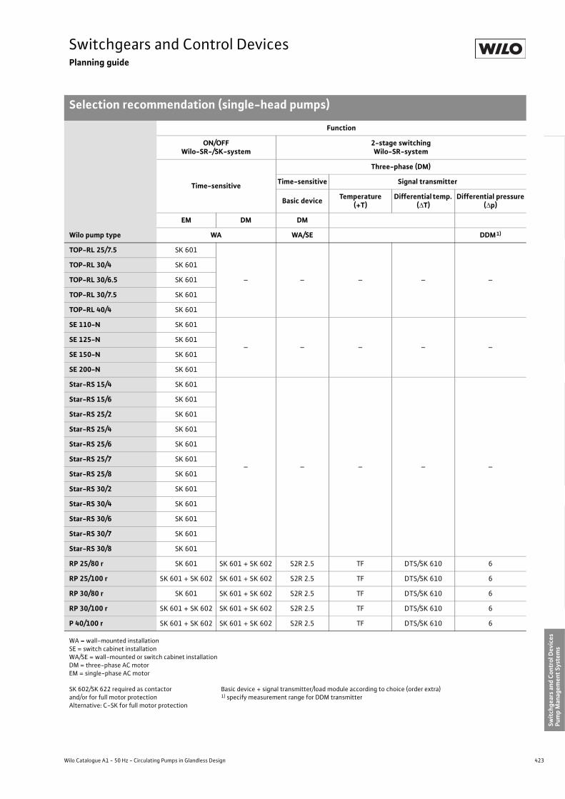
423
Switchgears and Control DevicesPlanning guide
Selection recommendation (single-head pumps)
Wilo Catalogue A1 - 50 Hz - Circulating Pumps in Glandless Design
Hea
ting,
Air-
cond
ition
ing,
Co
olin
gSe
cond
ary
Hot W
ater
Circ
ulat
ion
Sola
r The
rmal
, Geo
ther
mal
En
ergy
Sys
tem
sSe
rvic
e/Ac
cess
orie
s, S
yste
ms
Switc
hgea
rs a
nd C
ontr
ol D
evic
esPu
mp
Man
agem
ent S
yste
ms
TOP-RL 25/7.5 SK 601
– – – – –
TOP-RL 30/4 SK 601
TOP-RL 30/6.5 SK 601
TOP-RL 30/7.5 SK 601
TOP-RL 40/4 SK 601
SE 110-N SK 601
– – – – –SE 125-N SK 601
SE 150-N SK 601
SE 200-N SK 601
Star-RS 15/4 SK 601
– – – – –
Star-RS 15/6 SK 601
Star-RS 25/2 SK 601
Star-RS 25/4 SK 601
Star-RS 25/6 SK 601
Star-RS 25/7 SK 601
Star-RS 25/8 SK 601
Star-RS 30/2 SK 601
Star-RS 30/4 SK 601
Star-RS 30/6 SK 601
Star-RS 30/7 SK 601
Star-RS 30/8 SK 601
RP 25/80 r SK 601 SK 601 + SK 602 S2R 2.5 TF DTS/SK 610 6
RP 25/100 r SK 601 + SK 602 SK 601 + SK 602 S2R 2.5 TF DTS/SK 610 6
RP 30/80 r SK 601 SK 601 + SK 602 S2R 2.5 TF DTS/SK 610 6
RP 30/100 r SK 601 + SK 602 SK 601 + SK 602 S2R 2.5 TF DTS/SK 610 6
P 40/100 r SK 601 + SK 602 SK 601 + SK 602 S2R 2.5 TF DTS/SK 610 6
Wilo pump type
Function
ON/OFFWilo-SR-/SK-system
2-stage switchingWilo-SR-system
Time-sensitive
Three-phase (DM)
Time-sensitive Signal transmitter
Basic device Temperature(+T)
Differential temp. (�T)
Differential pressure(�p)
EM DM DM
WA WA/SE DDM1)
WA = wall-mounted installationSE = switch cabinet installationWA/SE = wall-mounted or switch cabinet installationDM = three-phase AC motorEM = single-phase AC motor
SK 602/SK 622 required as contactorand/or for full motor protectionAlternative: C-SK for full motor protection
Basic device + signal transmitter/load module according to choice (order extra)1) specify measurement range for DDM transmitter

424 Subject to change without prior notice 09/2007 WILO AG
Switchgears and Control DevicesPlanning guide
Selection recommendation (single-head pumps)
P 40/160 r
–
SK 601 + SK 602 S2R 2.5 TF DTS/SK 610 6
P 50/125 r SK 601 + SK 602 S2R 2.5 TF DTS/SK 610 6
P 50/160 r SK 601 + SK 602 S2R 2.5 TF DTS/SK 610 10
P 50/250 r SK 601 + SK 602 S2R 2.5 TF DTS/SK 610 16
P 65/125 r SK 601 + SK 602 S2R 2.5 TF DTS/SK 610 6
P 65/160 r SK 601 + SK 602 S2R 2.5 TF DTS/SK 610 10
P 65/250 r SK 601 + SK 602 S2R 2.5 TF DTS/SK 610 16
P 80/125 r SK 601 + SK 602 S2R 2.5 TF DTS/SK 610 6
P 80/160 r SK 601 + SK 602 S2R 2.5 TF DTS/SK 610 10
P 80/250 r SK 601 + SK 602 S2R 2.5 TF DTS/SK 610 16
P 100/160 r – SK 601 + SK 602 S2R 2.5 TF DTS/SK 610 16
P 100/200 r – SK 601 + SK 602 S2R 2.5 TF DTS/SK 610 16
TOP-D 30/40/50 SK 601 SK 601 + SK 602– – – –
TOP-D 65/80/100/125 SK 601 + SK 602 SK 601 + SK 602
Star-Z 15 SK 601–
– – – –
Star-Z 20/1 S1R-h
Star-Z 25/2 S1R-h
SK 601 + SK 602
TOP-Z 20/4 SK 601
TOP-Z 25/6 SK 601
TOP-Z 25/10 SK 601 + SK 602
TOP-Z 30/7 SK 601
TOP-Z 30/10 SK 601 + SK 602
TOP-Z 40/7 SK 601 + SK 602
TOP-Z 50/7, 65/10,80/10 –
Wilo pump type
Function
ON/OFFWilo-SR-/SK-system
2-stage switchingWilo-SR-system
Time-sensitive
Three-phase (DM)
Time-sensitive Signal transmitter
Basic device Temperature(+T)
Differential temp. (�T)
Differential pressure(�p)
EM DM DM
WA WA/SE DDM1)
WA = wall-mounted installationSE = switch cabinet installationWA/SE = wall-mounted or switch cabinet installationDM = three-phase AC motorEM = single-phase AC motor
SK 602/SK 622 required as contactorand/or for full motor protectionAlternative: C-SK for full motor protection
Basic device + signal transmitter/load module according to choice (order extra)1) specify measurement range for DDM transmitter

425
Switchgears and Control DevicesPlanning guide
Selection recommendation (single-head pumps)
Wilo Catalogue A1 - 50 Hz - Circulating Pumps in Glandless Design
Hea
ting,
Air-
cond
ition
ing,
Co
olin
gSe
cond
ary
Hot W
ater
Circ
ulat
ion
Sola
r The
rmal
, Geo
ther
mal
En
ergy
Sys
tem
sSe
rvic
e/Ac
cess
orie
s, S
yste
ms
Switc
hgea
rs a
nd C
ontr
ol D
evic
esPu
mp
Man
agem
ent S
yste
ms
Wilo pump type
Function
4-stage switchingWilo-SR-system
Stageless controlWilo-AS-system
Time-sensitive plus Differential pressure-sensitive (�p)
(+T/�T) (�p)
Basic device Load module signal transmitter Load module Signal
transmitter Basic device Signal transmitter
DM EM DM
WA/SE DDM WA/SE DDS1)
TOP-S 25/5
– – – –
AS 08 AS 08
6
TOP-S 25/7 6
TOP-S 25/10 10
TOP-S 30/4 6
TOP-S 25/13 16
TOP-S 30/5 6
TOP-S 30/7 6
TOP-S 30/10 10
TOP-S 40/4 6
TOP-S 40/7 6
TOP-S 40/10 – AS 08 10
TOP-S 40/15 – AS 08 16
TOP-S 50/4 AS 08 AS 08 6
TOP-S 50/7 – AS 08 6
TOP-S 50/10 – AS 08 10
TOP-S 50/15 – AS 1.5 16
TOP-S 65/7
– AS 08
10
TOP-S 65/10 16
TOP-S 65/13 16
TOP-S 65/15 – AS 1.5 16
TOP-S 80/7 – AS 08 10
TOP-S 80/10– AS 1.5
10
TOP-S 100/10 10
AXL 80/25-130 – – – – – AS 08 6
WA = wall-mounted installationSE = switch cabinet installationWA/SE = wall-mounted or switch cabinet installationDM = three-phase AC motorEM = single-phase AC motor
1) Order DDS signal transmitter separately (specify measuring range)

426 Subject to change without prior notice 09/2007 WILO AG
Switchgears and Control DevicesPlanning guide
Selection recommendation (single-head pumps)
TOP-RL 25/7.5
– – – – AS 08 –
6
TOP-RL 30/4 6
TOP-RL 30/6.5 6
TOP-RL 30/7.5 6
TOP-RL 40/4 6
SE 110-N
– – – – AS 08 –
6
SE 125-N 6
SE 150-N 6
SE 200-N 6
Star-RS 15/4
– – – – – –
Star-RS 15/6
Star-RS 25/2
Star-RS 25/4
Star-RS 25/6
Star-RS 25/7
Star-RS 25/8
Star-RS 30/2
Star-RS 30/4
Star-RS 30/6
Star-RS 30/7
Star-RS 30/8
RP 25/80 r S4R 2.5 T/�T MOD + sensor �p MOD 6 – –
RP 25/100 r S4R 2.5 T/�T MOD + sensor �p MOD 6 AS 08 AS 08 6
RP 30/80 r S4R 2.5 T/�T MOD + sensor �p MOD 6 – –
RP 30/100 r S4R 2.5 T/�T MOD + sensor �p MOD 6 AS 08 AS 08 6
P 40/100 r S4R 2.5 T/�T MOD + sensor �p MOD 6 AS 08 AS 08 6
P 40/160 r S4R 2.5 T/�T MOD + sensor �p MOD 6 – AS 08 6
P 50/125 r S4R 2.5 T/�T MOD + sensor �p MOD 6 – AS 08 6
Wilo pump type
Function
4-stage switchingWilo-SR-system
Stageless controlWilo-AS-system
Time-sensitive plus Differential pressure-sensitive (�p)
(+T/�T) (�p)
Basic device Load module signal transmitter Load module Signal
transmitter Basic device Signal transmitter
DM EM DM
WA/SE DDM WA/SE DDS1)
WA = wall-mounted installationSE = switch cabinet installationWA/SE = wall-mounted or switch cabinet installationDM = three-phase AC motorEM = single-phase AC motor
1) Order DDS signal transmitter separately (specify measuring range)

427
Switchgears and Control DevicesPlanning guide
Selection recommendation (single-head pumps)
Wilo Catalogue A1 - 50 Hz - Circulating Pumps in Glandless Design
Hea
ting,
Air-
cond
ition
ing,
Co
olin
gSe
cond
ary
Hot W
ater
Circ
ulat
ion
Sola
r The
rmal
, Geo
ther
mal
En
ergy
Sys
tem
sSe
rvic
e/Ac
cess
orie
s, S
yste
ms
Switc
hgea
rs a
nd C
ontr
ol D
evic
esPu
mp
Man
agem
ent S
yste
ms
P 50/160 r S4R 2.5 T/�T MOD + sensor �p MOD 10 – AS 08 10
P 50/250 r S4R 2.5 T/�T MOD + sensor �p MOD 16 – AS 1.5 16
P 65/125 r S4R 2.5 T/�T MOD + sensor �p MOD 6 – AS 08 6
P 65/160 r S4R 2.5 T/�T MOD + sensor �p MOD 10 – AS 08 10
P 65/250 r S4R 2.5 T/�T MOD + sensor �p MOD 16 – AS 1.5 16
P 80/125 r S4R 2.5 T/�T MOD + sensor �p MOD 6 – AS 08 6
P 80/160 r S4R 2.5 T/�T MOD + sensor �p MOD 10 – AS 08 10
P 80/250 r S4R 2.5 T/�T MOD + sensor �p MOD 16 – – –
P 100/160 r S4R 2.5 T/�T MOD + sensor �p MOD 10 – AS 1.5 10
P 100/200 r S4R 2.5 T/�T MOD + sensor �p MOD 16 – – –
TOP-D 30/40/50– – – – – –
TOP-D 65/80/100/125
Star-Z 15
– – – – – –
Star-Z 20/1
Star-Z 25/2
TOP-Z 20/4
TOP-Z 25/6
TOP-Z 25/10
TOP-Z 30/7
TOP-Z 30/10
TOP-Z 40/7
TOP-Z 50/7, 65/10,80/10
Wilo pump type
Function
4-stage switchingWilo-SR-system
Stageless controlWilo-AS-system
Time-sensitive plus Differential pressure-sensitive (�p)
(+T/�T) (�p)
Basic device Load module signal transmitter Load module Signal
transmitter Basic device Signal transmitter
DM EM DM
WA/SE DDM WA/SE DDS1)
WA = wall-mounted installationSE = switch cabinet installationWA/SE = wall-mounted or switch cabinet installationDM = three-phase AC motorEM = single-phase AC motor
1) Order DDS signal transmitter separately (specify measuring range)

428 Subject to change without prior notice 09/2007 WILO AG
Switchgears and Control DevicesPlanning guide
Selection recommendation (single-head pumps)
Wilo pump type
Function
Stageless speed controlWilo-CR-system
Manual controlmode
Differential pressure (�p) Temperature
�p-c
Basic device DDC �p-v / �p-q 1) Signal transmitter ±T �T
DM DDG3)
WA or SE
TOP-S 25/5– – – – –
TOP-S 25/7
TOP-S 25/10 CR 1.1-1 DDC board Basic equipment 10 Temperature board
TOP-S 25/13 – – – – –
TOP-S 30/4
– – – – –TOP-S 30/5
TOP-S 30/7
TOP-S 30/10 CR 1.1–1
DDC board Basic equipment
10
Temperature board 2)
TOP-S 40/4 – –
TOP-S 40/7CR 1.1–1
10
TOP-S 40/10 10
TOP-S 40/15 CR 2.2-1 20
TOP-S 50/4
CR 1.1–1
10
TOP-S 50/7 10
TOP-S 50/10 10
TOP-S 50/15 CR 2.2–1 20
TOP-S 65/7 CR 1.1–1 10
TOP-S 65/10 CR 1.1–1 10
TOP-S 65/13 CR 2.2–1 20
TOP-S 65/15 CR 2.2–1 20
TOP-S 80/7 CR 1.1–1 10
TOP-S 80/10 CR 2.2–1 10
TOP-S 100/10 CR 2.2–1 10
AXL 80/25-130 – – – – –
WA = wall-mounted installationSE = switch cabinet installationWA/SE = wall-mounted or switch cabinet installationDM = three-phase AC motorEM = single-phase AC motor
1) Required volume flow transmitter to be provided by customer2) Order temperature board separately as required:
Temperature board KTY 10: Temperature sensor TSG in the scope of delivery Temperature board PT 100: Temperature sensor to be provided onsite
3) Order DDG signal transmitter separately (specify measuring range)

429
Switchgears and Control DevicesPlanning guide
Selection recommendation (single-head pumps)
Wilo Catalogue A1 - 50 Hz - Circulating Pumps in Glandless Design
Hea
ting,
Air-
cond
ition
ing,
Co
olin
gSe
cond
ary
Hot W
ater
Circ
ulat
ion
Sola
r The
rmal
, Geo
ther
mal
En
ergy
Sys
tem
sSe
rvic
e/Ac
cess
orie
s, S
yste
ms
Switc
hgea
rs a
nd C
ontr
ol D
evic
esPu
mp
Man
agem
ent S
yste
ms
TOP-RL 25/7.5
– – – – –
TOP-RL 30/4
TOP-RL 30/6.5
TOP-RL 30/7.5
TOP-RL 40/4
SE 110-N
– – – – –SE 125-N
SE 150-N
SE 200-N
Star-RS 15/4
– – – – –
Star-RS 15/6
Star-RS 25/2
Star-RS 25/4
Star-RS 25/6
Star-RS 25/7
Star-RS 25/8
Star-RS 30/2
Star-RS 30/4
Star-RS 30/6
Star-RS 30/7
Star-RS 30/8
RP 25/80 r
– – – – –RP 25/100 r
RP 30/80 r
RP 30/100 r
Wilo pump type
Function
Stageless speed controlWilo-CR-system
Manual controlmode
Differential pressure (�p) Temperature
�p-c
Basic device DDC �p-v / �p-q 1) Signal transmitter ±T �T
DM DDG3)
WA or SE
WA = wall-mounted installationSE = switch cabinet installationWA/SE = wall-mounted or switch cabinet installationDM = three-phase AC motorEM = single-phase AC motor
1) Required volume flow transmitter to be provided by customer2) Order temperature board separately as required:
Temperature board KTY 10: Temperature sensor TSG in the scope of delivery Temperature board PT 100: Temperature sensor to be provided onsite
3) Order DDG signal transmitter separately (specify measuring range)

430 Subject to change without prior notice 09/2007 WILO AG
Switchgears and Control DevicesPlanning guide
Selection recommendation (single-head pumps)
P 40/100 r – – – – –
P 40/160 r CR 1.1–1
DDC-Board Basic equipment
10
Temperatureboard 2)
P 50/125 r CR 1.1–1 10
P 50/160 r CR 1.1–1 10
P 50/250 r CR 2.2–1 20
P 65/125 r CR 1.1–1 10
P 65/160 r CR 1.1–1 10
P 65/250 r CR 3.0–1 20
P 80/125 r CR 1.1–1 10
P 80/160 r CR 2.2–1 10
P 80/250 r CR 4.0–1 20
P 100/160 r CR 2.2–1 10
P 100/200 r CR 4.0–1 20
TOP-D 30/40/50– – – – –
TOP-D 65/80/100/125
Star-Z 15
– – – – –
Star-Z 20/1
Star-Z 25/2
TOP-Z 20/4
TOP-Z 25/6
TOP-Z 25/10
TOP-Z 30/7
TOP-Z 30/10
TOP-Z 40/7
TOP-Z 50/7, 65/10,TOP-Z 80/10
Wilo pump type
Function
Stageless speed controlWilo-CR-system
Manual controlmode
Differential pressure (�p) Temperature
�p-c
Basic device DDC �p-v / �p-q 1) Signal transmitter ±T �T
DM DDG3)
WA or SE
WA = wall-mounted installationSE = switch cabinet installationWA/SE = wall-mounted or switch cabinet installationDM = three-phase AC motorEM = single-phase AC motor
1) Required volume flow transmitter to be provided by customer2) Order temperature board separately as required:
Temperature board KTY 10: Temperature sensor TSG in the scope of delivery Temperature board PT 100: Temperature sensor to be provided onsite
3) Order DDG signal transmitter separately (specify measuring range)

431
Switchgears and Control DevicesPlanning guide
Selection recommendation (twin-head pumps or 2 single-head pumps)
Wilo Catalogue A1 - 50 Hz - Circulating Pumps in Glandless Design
Hea
ting,
Air-
cond
ition
ing,
Co
olin
gSe
cond
ary
Hot W
ater
Circ
ulat
ion
Sola
r The
rmal
, Geo
ther
mal
En
ergy
Sys
tem
sSe
rvic
e/Ac
cess
orie
s, S
yste
ms
Switc
hgea
rs a
nd C
ontr
ol D
evic
esPu
mp
Man
agem
ent S
yste
ms
Pump type
Function
2-pump switching or parallel operation (Maximum/Min.)
Wilo-SR-system
AC (EM) Three-phase (DM)
Time-sensitive Signal transmitter Time-
sensitive Signal transmitter
Basic device
Temperature(+T)
Differentialtemp. (�T)
Differential pressure (�p)
Basic device
Temperature(+T)
Differential temp. (�T)
Differential pressure (�p)
Twin-head pumps
2 single-head pumps
EM DM
WA/SE DDM1) WA/SE DDM1)
– 2 x TOP-S 25/5 S2R 3D TF DTS/SK 610 6 S2R 3D TF DTS/SK 610 6
– 2 x TOP-S 25/7 S2R 3D TF DTS/SK 610 6 S2R 3D TF DTS/SK 610 6
– 2 x TOP-S 25/10 S2R 3D TF DTS/SK 610 6 S2R 3D TF DTS/SK 610 10
– 2 x TOP-S 25/13 S2R 3D TF DTS/SK 610 16 S2R 3D TF DTS/SK 610 16
– 2 x TOP-S 30/4 S2R 3D TF DTS/SK 610 6 S2R 3D TF DTS/SK 610 6
TOP-SD 30/5 2 x TOP-S 30/5 S2R 3D TF DTS/SK 610 6 S2R 3D TF DTS/SK 610 6
TOP-SD 32/7 2 x TOP-S 30/7 S2R 3D TF DTS/SK 610 6 S2R 3D TF DTS/SK 610 6
TOP-SD 32/10 2 x TOP-S 30/10 S2R 3D TF DTS/SK 610 10 S2R 3D TF DTS/SK 610 10
– 2 x TOP-S 40/4 S2R 3D TF DTS/SK 610 6 S2R 3D TF DTS/SK 610 6
TOP-SD 40/3 – S2R 3D TF DTS/SK 610 6 S2R 3D TF DTS/SK 610 6
TOP-SD 40/7 2 x TOP-S 40/7 S2R 3D TF DTS/SK 610 6 S2R 3D TF DTS/SK 610 6
TOP-SD 40/10 2 x TOP-S 40/10 S2R 3D TF DTS/SK 610 10 S2R 3D TF DTS/SK 610 10
– 2 x TOP-S 50/4 S2R 3D TF DTS/SK 610 6 S2R 3D TF DTS/SK 610 6
TOP-SD 50/7 2 x TOP-S 50/7 S2R 3D TF DTS/SK 610 6 S2R 3D TF DTS/SK 610 6
TOP-SD 50/10 2 x TOP-S 50/10 S2R 3D TF DTS/SK 610 10 S2R 3D TF DTS/SK 610 10
TOP-SD 40/15 2 x TOP-S 40/15 S2R 3D TF DTS/SK 610 16 S2R 3D TF DTS/SK 610 16
TOP-SD 50/15 2 x TOP-S 50/15 – – – – S2R 3D TF DTS/SK 610 16
– 2 x TOP-S 65/7 S2R 3D TF DTS/SK 610 10 S2R 3D TF DTS/SK 610 10
TOP-SD 65/10 2 x TOP-S 65/10 S2R 3D TF DTS/SK 610 10 S2R 3D TF DTS/SK 610 10
TOP-SD 65/13 2 x TOP-S 65/13– – – –
S2R 3D TF DTS/SK 610 16
TOP-SD 65/15 2 x TOP-S 65/15 S2R 3D TF DTS/SK 610 16
TOP-SD 80/ 7 (only 1~) 2 x TOP-S 80/7 S2R 3D TF DTS/SK 610 10 S2R 3D TF DTS/SK 610 10
TOP-SD 80/10 2 x TOP-S 80/10– – – –
S2R 3D TF DTS/SK 610 10
– 2 x TOP-S 100/10 S2R 3D TF DTS/SK 610 10
– 2 x AXL 80/25-130 – – – – S2R 3D TF DTS/SK 610 6
WA = wall-mounted installationSE = switch cabinet installationWA/SE = wall-mounted or switch cabinet installationDM = three-phase AC motorEM = single-phase AC motor
Basic device + signal transmitter/load module as required (order separately)
1) Specify measurement range for transmitter DDM

432 Subject to change without prior notice 09/2007 WILO AG
Switchgears and Control DevicesPlanning guide
Selection recommendation (twin-head pumps or 2 single-head pumps)
– 2 x TOP-RL 25/7.5 S2R 3D TF DTS/SK 610 10
– – – –
– 2 x TOP-RL 30/4 S2R 3D TF DTS/SK 610 6
– 2 x TOP-RL 30/6.5 S2R 3D TF DTS/SK 610 10
– 2 x TOP-RL 30/7.5 S2R 3D TF DTS/SK 610 10
– 2 x TOP-RL 40/4 S2R 3D TF DTS/SK 610 6
– 2 x SE 110-N S2R 3D TF DTS/SK 610 6
– – – –SE 125-N-TW 2 x SE 125-N S2R 3D TF DTS/SK 610 6
SE 150-N-TW 2 x SE 150-N S2R 3D TF DTS/SK 610 6
SE 200-N-TW 2 x SE 200-N S2R 3D TF DTS/SK 610 10
– 2 x RP 25/80 r S2R 3D TF DTS/SK 610 6 S2R 3D TF DTS/SK 610 6
– 2 x RP 25/100 r S2R 3D TF DTS/SK 610 6 S2R 3D TF DTS/SK 610 6
DOP 32/80 r 2 x RP 30/80 r S2R 3D TF DTS/SK 610 6 S2R 3D TF DTS/SK 610 6
– 2 x RP 30/100 r S2R 3D TF DTS/SK 610 6 S2R 3D TF DTS/SK 610 6
DOP 40/100 r 2 x P 40/100 r S2R 3D TF DTS/SK 610 6 S2R 3D TF DTS/SK 610 6
DOP 40/160 r 2 x P 40/160 r
– – – –
S2R 3D TF DTS/SK 610 6
DOP 50/100 r 2 x P 50/125 r S2R 3D TF DTS/SK 610 6
DOP 50/160 r 2 x P 50/160 r S2R 3D TF DTS/SK 610 10
– 2 x P 50/250 r S2R 3D TF DTS/SK 610 6
DOP 65/125 r 2 x P 65/125 r S2R 3D TF DTS/SK 610 6
DOP 65/160 r 2 x P 65/160 r S2R 3D TF DTS/SK 610 10
– 2 x P 65/250 r S2R 3D TF DTS/SK 610 16
DOP 80/125 r 2 x P 80/125 r S2R 3D TF DTS/SK 610 6
DOP 80/160 r 2 x P 80/160 r S2R 3D TF DTS/SK 610 10
– 2 x P 80/250 r S2R 3D TF DTS/SK 610 16
DOP 100/160 r 2 x P 100/160 r S2R 3D TF DTS/SK 610 10
– 2 x P 100/200 r S2R 3D TF DTS/SK 610 16
Pump type
Function
2-pump switching or parallel operation (Maximum/Min.)
Wilo-SR-system
AC (EM) Three-phase (DM)
Time-sensitive Signal transmitter Time-
sensitive Signal transmitter
Basic device
Temperature(+T)
Differentialtemp. (�T)
Differential pressure (�p)
Basic device
Temperature(+T)
Differential temp. (�T)
Differential pressure (�p)
Twin-head pumps
2 single-head pumps
EM DM
WA/SE DDM1) WA/SE DDM1)
WA = wall-mounted installationSE = switch cabinet installationWA/SE = wall-mounted or switch cabinet installationDM = three-phase AC motorEM = single-phase AC motor
Basic device + signal transmitter/load module as required (order separately)
1) Specify measurement range for transmitter DDM
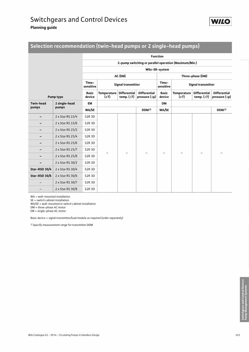
433
Switchgears and Control DevicesPlanning guide
Selection recommendation (twin-head pumps or 2 single-head pumps)
Wilo Catalogue A1 - 50 Hz - Circulating Pumps in Glandless Design
Hea
ting,
Air-
cond
ition
ing,
Co
olin
gSe
cond
ary
Hot W
ater
Circ
ulat
ion
Sola
r The
rmal
, Geo
ther
mal
En
ergy
Sys
tem
sSe
rvic
e/Ac
cess
orie
s, S
yste
ms
Switc
hgea
rs a
nd C
ontr
ol D
evic
esPu
mp
Man
agem
ent S
yste
ms
– 2 x Star RS 15/4 S2R 3D
– – – – – – –
– 2 x Star RS 15/6 S2R 3D
– 2 x Star RS 25/2 S2R 3D
– 2 x Star RS 25/4 S2R 3D
– 2 x Star RS 25/6 S2R 3D
– 2 x Star RS 25/7 S2R 3D
– 2 x Star RS 25/8 S2R 3D
– 2 x Star RS 30/2 S2R 3D
Star-RSD 30/4 2 x Star RS 30/4 S2R 3D
Star-RSD 30/6 2 x Star RS 30/6 S2R 3D
– 2 x Star RS 30/7 S2R 3D
– 2 x Star RS 30/8 S2R 3D
Pump type
Function
2-pump switching or parallel operation (Maximum/Min.)
Wilo-SR-system
AC (EM) Three-phase (DM)
Time-sensitive Signal transmitter Time-
sensitive Signal transmitter
Basic device
Temperature(+T)
Differentialtemp. (�T)
Differential pressure (�p)
Basic device
Temperature(+T)
Differential temp. (�T)
Differential pressure (�p)
Twin-head pumps
2 single-head pumps
EM DM
WA/SE DDM1) WA/SE DDM1)
WA = wall-mounted installationSE = switch cabinet installationWA/SE = wall-mounted or switch cabinet installationDM = three-phase AC motorEM = single-phase AC motor
Basic device + signal transmitter/load module as required (order separately)
1) Specify measurement range for transmitter DDM

434 Subject to change without prior notice 09/2007 WILO AG
Switchgears and Control DevicesPlanning guide
Selection recommendation (twin-head pumps or 2 single-head pumps)
Pump type
Function
4-stage switching Stageless control
Wilo-SR-system Wilo-AS-system
Basic device
Time-sensitive plus Differential pressure (�p)
(+T/�T) (�p)
Load module
Signaltransmitter
Load module
Signaltransmitter Basic device Signal
transmitter
Twin-head pumps
2 single-head pumps
DM EM DM
WA/SE DDM WA/SE DDS1)
– 2 x TOP-S 25/5
– – – – –
2 x AS 08 + SK 613
2 x AS 08 + SK 613
6
– 2 x TOP-S 25/7 6
2 x TOP-S 25/10 10
– 2 x TOP-S 25/13 16
– 2 x TOP-S 30/4 6
TOP-SD 30/5 2 x TOP-S 30/5 6
TOP-SD 32/7 2 x TOP-S 30/7 6
TOP-SD 32/10 2 x TOP-S 30/10 10
– 2 x TOP-S 40/4 6
TOP-SD 40/3 – 6
TOP-SD 40/7 2 x TOP-S 40/7 6
TOP-SD 40/10 2 x TOP-S 40/10 – 10
TOP-SD 40/15 2 x TOP-S 40/15 – 2 x AS 1.5 + SK 613 16
– 2 x TOP-S 50/4 2 x AS 08 + SK 613
2 x AS 08 + SK 613 6
TOP-SD 50/7 2 x TOP-S 50/7 – 2 x AS 08 + SK 613 6
TOP-SD 50/10 2 x TOP-S 50/10 – 2 x AS 08 + SK 613 10
TOP-SD 50/15 2 x TOP-S 50/15 – 2 x AS 1.5 + SK 613 16
– 2 x TOP-S 65/7
– 2 x AS 08 + SK 613
10
TOP-SD 65/10 2 x TOP-S 65/10 10
TOP-SD 65/13 2 x TOP-S 65/13 16
TOP-SD 65/15 2 x TOP-S 65/15 – 2 x AS 1.5 + SK 613 16
TOP-SD 80/7(only 1~) 2 x TOP-S 80/7 – 2 x AS 08 +
SK 613 10
TOP-SD 80/10 2 x TOP-S 80/10– 2 x AS 1.5 +
SK 613
10
– 2 x TOP-S 100/10 10
WA = wall-mounted installationSE = switch cabinet installationWA/SE = wall-mounted or switch cabinet installationDM = three-phase AC motorEM = single-phase AC motor
1) Order DDS signal transmitter separately (specify measuring range)

435
Switchgears and Control DevicesPlanning guide
Selection recommendation (twin-head pumps or 2 single-head pumps)
Wilo Catalogue A1 - 50 Hz - Circulating Pumps in Glandless Design
Hea
ting,
Air-
cond
ition
ing,
Co
olin
gSe
cond
ary
Hot W
ater
Circ
ulat
ion
Sola
r The
rmal
, Geo
ther
mal
En
ergy
Sys
tem
sSe
rvic
e/Ac
cess
orie
s, S
yste
ms
Switc
hgea
rs a
nd C
ontr
ol D
evic
esPu
mp
Man
agem
ent S
yste
ms
– 2 x AXL 80/25-130 – – – – – – 2 x AS 08 + SK 613 6
– 2 x TOP-RL 25/7.5
– – – – – 2 x AS 08 + SK 613 –
6
– 2 x TOP-RL 30/4 6
– 2 x TOP-RL 30/6.5 6
– 2 x TOP-RL 30/7.5 6
– 2 x TOP-RL 40/4 6
– 2 x SE 110-N 6
SE 125-N-TW 2 x SE 125-N 6
SE 150-N-TW 2 x SE 150-N 6
SE 200-N-TW 2 x SE 200-N 6
– 2 x RP 25/80 r S4R 2.5 D T/�T MOD + sensor �p MOD 6 – – –
– 2 x RP 25/100 r S4R 2.5 D T/�T MOD + sensor �p MOD 6 2 x AS 08 + SK 613
2 x AS 08 + SK 613 6
DOP 32/80 r 2 x RP 30/80 r S4R 2.5 D T/�T MOD + sensor �p MOD 6 – –
– 2 x RP 30/100 r S4R 2.5 D T/�T MOD + sensor �p MOD 6 2 x AS 08 + SK 613
2 x AS 08 + SK 613
6
DOP 40/100 r 2 x P 40/100 r S4R 2.5 D T/�T MOD + sensor �p MOD 6 6
DOP 40/160 r 2 x P 40/160 r S4R 2.5 D T/�T MOD + sensor �p MOD 6– 2 x AS 08 +
SK 613
6
DOP 50/100 r 2 x P 50/125 r S4R 2.5 D T/�T MOD + sensor �p MOD 6 6
DOP 50/160 r 2 x P 50/160 r S4R 2.5 D T/�T MOD + sensor �p MOD 10 – 2 x AS 08 + SK 613 6
– 2 x P 50/250 r S4R 2.5 D T/�T MOD + sensor �p MOD 16 – 2 x AS 1.5 + SK 613 16
DOP 65/125 r 2 x P 65/125 r S4R 2.5 D T/�T MOD + sensor �p MOD 6– 2 x AS 08 +
SK 613
6
DOP 65/160 r 2 x P 65/160 r S4R 2.5 D T/�T MOD + sensor �p MOD 10 10
– 2 x P 65/250 r S4R 2.5 D T/�T MOD + sensor �p MOD 16 – 2 x AS 1.5 + SK 613 16
DOP 80/125 r 2 x P 80/125 r S4R 2.5 D T/�T MOD + sensor �p MOD 6– 2 x AS 08 +
SK 6136
DOP 80/160 r 2 x P 80/160 r S4R 2.5 D T/�T MOD + sensor �p MOD 10 10
– 2 x P 80/250 r S4R 2.5 D T/�T MOD + sensor �p MOD 16 – – –
Pump type
Function
4-stage switching Stageless control
Wilo-SR-system Wilo-AS-system
Basic device
Time-sensitive plus Differential pressure (�p)
(+T/�T) (�p)
Load module
Signaltransmitter
Load module
Signaltransmitter Basic device Signal
transmitter
Twin-head pumps
2 single-head pumps
DM EM DM
WA/SE DDM WA/SE DDS1)
WA = wall-mounted installationSE = switch cabinet installationWA/SE = wall-mounted or switch cabinet installationDM = three-phase AC motorEM = single-phase AC motor
1) Order DDS signal transmitter separately (specify measuring range)

436 Subject to change without prior notice 09/2007 WILO AG
Switchgears and Control DevicesPlanning guide
Selection recommendation (twin-head pumps or 2 single-head pumps)
DOP 100/160 r 2 x P 100/160 r S4R 2.5 D T/�T MOD + sensor �p MOD 10 – 2 x AS 1.5 + SK 613 10
– 2 x P 100/200 r S4R 2.5 D T/�T MOD + sensor �p MOD 16 – – –
– 2 x Star RS 15/4
– – – – – – –
– 2 x Star RS 15/6
– 2 x Star RS 25/2
– 2 x Star RS 25/4
– 2 x Star RS 25/6
– 2 x Star RS 25/7
– 2 x Star RS 25/8
– 2 x Star RS 30/2
Star-RSD 30/4 2 x Star RS 30/4 r
Star-RSD 30/6 2 x Star RS 30/6
– 2 x Star RS 30/7
– 2 x Star RS 30/8
Pump type
Function
4-stage switching Stageless control
Wilo-SR-system Wilo-AS-system
Basic device
Time-sensitive plus Differential pressure (�p)
(+T/�T) (�p)
Load module
Signaltransmitter
Load module
Signaltransmitter Basic device Signal
transmitter
Twin-head pumps
2 single-head pumps
DM EM DM
WA/SE DDM WA/SE DDS1)
WA = wall-mounted installationSE = switch cabinet installationWA/SE = wall-mounted or switch cabinet installationDM = three-phase AC motorEM = single-phase AC motor
1) Order DDS signal transmitter separately (specify measuring range)
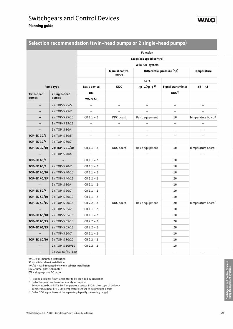
437
Switchgears and Control DevicesPlanning guide
Selection recommendation (twin-head pumps or 2 single-head pumps)
Wilo Catalogue A1 - 50 Hz - Circulating Pumps in Glandless Design
Hea
ting,
Air-
cond
ition
ing,
Co
olin
gSe
cond
ary
Hot W
ater
Circ
ulat
ion
Sola
r The
rmal
, Geo
ther
mal
En
ergy
Sys
tem
sSe
rvic
e/Ac
cess
orie
s, S
yste
ms
Switc
hgea
rs a
nd C
ontr
ol D
evic
esPu
mp
Man
agem
ent S
yste
ms
Pump type
Function
Stageless speed control
Wilo-CR-system
Manual control mode
Differential pressure (�p) Temperature
�p-c
Basic device DDC �p-v/�p-q 1) Signal transmitter ±T �T
Twin-head pumps
2 single-head pumps
DM DDG3)
WA or SE
– 2 x TOP-S 25/5 – – – – –
– 2 x TOP-S 25/7 – – – – –
– 2 x TOP-S 25/10 CR 1.1 – 2 DDC board Basic equipment 10 Temperature board2)
– 2 x TOP-S 25/13 – – – – –
– 2 x TOP-S 30/4 – – – – –
TOP-SD 30/5 2 x TOP-S 30/5 – – – – –
TOP-SD 32/7 2 x TOP-S 30/7 – – – – –
TOP-SD 32/10 2 x TOP-S 30/10 CR 1.1 – 2 DDC board Basic equipment 10 Temperature board2)
– 2 x TOP-S 40/4 – – – – –
TOP-SD 40/3 – CR 1.1 – 2
DDC board Basic equipment
10
Temperature board2)
TOP-SD 40/7 2 x TOP-S 40/7 CR 1.1 – 2 10
TOP-SD 40/10 2 x TOP-S 40/10 CR 1.1 – 2 10
TOP-SD 40/15 2 x TOP-S 40/15 CR 2.2 – 2 20
– 2 x TOP-S 50/4 CR 1.1 – 2 10
TOP-SD 50/7 2 x TOP-S 50/7 CR 1.1 – 2 10
TOP-SD 50/10 2 x TOP-S 50/10 CR 1.1 – 2 10
TOP-SD 50/15 2 x TOP-S 50/15 CR 2.2 – 2 20
– 2 x TOP-S 65/7 CR 1.1 – 2 10
TOP-SD 65/10 2 x TOP-S 65/10 CR 1.1 – 2 10
TOP-SD 65/13 2 x TOP-S 65/13 CR 2.2 – 2 20
TOP-SD 65/15 2 x TOP-S 65/15 CR 2.2 – 2 20
– 2 x TOP-S 80/7 CR 1.1 – 2 10
TOP-SD 80/10 2 x TOP-S 80/10 CR 2.2 – 2 10
– 2 x TOP-S 100/10 CR 2.2 – 2 10
– 2 x AXL 80/25-130 – – – – –
WA = wall-mounted installationSE = switch cabinet installationWA/SE = wall-mounted or switch cabinet installationDM = three-phase AC motorEM = single-phase AC motor
1) Required volume flow transmitter to be provided by customer2) Order temperature board separately as required:
Temperature board KTY 10: Temperature sensor TSG in the scope of delivery Temperature board PT 100: Temperature sensor to be provided onsite
3) Order DDG signal transmitter separately (specify measuring range)
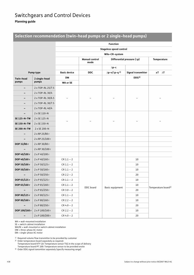
438 Subject to change without prior notice 09/2007 WILO AG
Switchgears and Control DevicesPlanning guide
Selection recommendation (twin-head pumps or 2 single-head pumps)
– 2 x TOP-RL 25/7.5
– – – – –
– 2 x TOP-RL 30/4
– 2 x TOP-RL 30/6.5
– 2 x TOP-RL 30/7.5
– 2 x TOP-RL 40/4
– 2 x SE 110-N
– – – – –SE 125-N-TW 2 x SE 125-N
SE 150-N-TW 2 x SE 150-N
SE 200-N-TW 2 x SE 200-N
– 2 x RP 25/80 r
– 2 x RP 25/100 r
DOP 32/80 r 2 x RP 30/80 r
– 2 x RP 30/100 r
DOP 40/100 r 2 x P 40/100 r
DOP 40/160 r 2 x P 40/160 r CR 1.1 – 2
DDC board Basic equipment
10
Temperature board2)
DOP 50/100 r 2 x P 50/125 r CR 1.1 – 2 10
DOP 50/160 r 2 x P 50/160 r CR 1.1 – 2 10
– 2 x P 50/250 r CR 2.2 – 2 20
DOP 65/125 r 2 x P 65/125 r CR 1.1 – 2 10
DOP 65/160 r 2 x P 65/160 r CR 1.1 – 2 10
– 2 x P 65/250 r CR 3.0 – 2 20
DOP 80/125 r 2 x P 80/125 r CR 1.1 – 2 10
DOP 80/160 r 2 x P 80/160 r CR 2.2 – 2 10
– 2 x P 80/250 r CR 4.0 – 2 20
DOP 100/160 r 2 x P 100/160 r CR 2.2 – 2 10
– 2 x P 100/200 r CR 4.0 – 2 20
Pump type
Function
Stageless speed control
Wilo-CR-system
Manual control mode
Differential pressure (�p) Temperature
�p-c
Basic device DDC �p-v/�p-q 1) Signal transmitter ±T �T
Twin-head pumps
2 single-head pumps
DM DDG3)
WA or SE
WA = wall-mounted installationSE = switch cabinet installationWA/SE = wall-mounted or switch cabinet installationDM = three-phase AC motorEM = single-phase AC motor
1) Required volume flow transmitter to be provided by customer2) Order temperature board separately as required:
Temperature board KTY 10: Temperature sensor TSG in the scope of delivery Temperature board PT 100: Temperature sensor to be provided onsite
3) Order DDG signal transmitter separately (specify measuring range)

439
Switchgears and Control DevicesPlanning guide
Selection recommendation (twin-head pumps or 2 single-head pumps)
Wilo Catalogue A1 - 50 Hz - Circulating Pumps in Glandless Design
Hea
ting,
Air-
cond
ition
ing,
Co
olin
gSe
cond
ary
Hot W
ater
Circ
ulat
ion
Sola
r The
rmal
, Geo
ther
mal
En
ergy
Sys
tem
sSe
rvic
e/Ac
cess
orie
s, S
yste
ms
Switc
hgea
rs a
nd C
ontr
ol D
evic
esPu
mp
Man
agem
ent S
yste
ms
– 2 x Star RS 15/4
– – – – –
– 2 x Star RS 15/6
– 2 x Star RS 25/2
– 2 x Star RS 25/4
– 2 x Star RS 25/6
– 2 x Star RS 25/7
– 2 x Star RS 25/8
– 2 x Star RS 30/2
Star-RSD 30/4 2 x Star RS 30/4
Star-RSD 30/6 2 x Star RS 30/6
– 2 x Star RS 30/7
– 2 x Star RS 30/8
Pump type
Function
Stageless speed control
Wilo-CR-system
Manual control mode
Differential pressure (�p) Temperature
�p-c
Basic device DDC �p-v/�p-q 1) Signal transmitter ±T �T
Twin-head pumps
2 single-head pumps
DM DDG3)
WA or SE
WA = wall-mounted installationSE = switch cabinet installationWA/SE = wall-mounted or switch cabinet installationDM = three-phase AC motorEM = single-phase AC motor
1) Required volume flow transmitter to be provided by customer2) Order temperature board separately as required:
Temperature board KTY 10: Temperature sensor TSG in the scope of delivery Temperature board PT 100: Temperature sensor to be provided onsite
3) Order DDG signal transmitter separately (specify measuring range)

440 Subject to change without prior notice 09/2007 WILO AG
Switchgears and Control DevicesPlanning guide
Selection Guide
This selection recommendation is in reference to installation systems which are designed as per the German Heating Installation Ordinance [Heizungsanlagenverordnung (HeizAnlV)]and the German Energy Savings Ordinance [Energieeinsparverordnung (EnEV)].
Control functionTime Temperature Differential
temperatureDifferential pres-
sure
Differential pressure with temperature
prompt
H T �T �p Feed Return
Switchgear/control device type
Pipe systemMode of utilisation/operating mode
Wilo
-SK
601
Wilo
-S1R
-h
Wilo
-S2R
…W
ilo-S
4R…
Wilo
-CR.
..
Wilo
-S2R
…
Wilo
-S4R
…
Wilo
-CR.
...
Wilo
-S2R
…
Wilo
-S4R
…
Wilo
-AS…
�P
Wilo
-CR.
...
Wilo
-Str
atos
...W
ilo-T
OP-
E…
Twin-pipe system- with thermostatic valves
• • • • •
Twin-pipe system- with manual control valves
• • • •
Single-pipe system- with space heating panels
• • • •
Single-pipe system- with radiant panel heating
• • • •
Partial gravity
•
Open system
•
Boiler admixture for- minimum return tempera-
ture- minimum flow volume
• • • •
Primary circuit
• • • • •
Primary circuit with con-densing boiler
• • •
Secondary hot water cir-culation
• •
Air heating/cooling cir-cuits
• • • •

441
Switchgears and Control DevicesPlanning guide
Wilo Catalogue A1 - 50 Hz - Circulating Pumps in Glandless Design
Hea
ting,
Air-
cond
ition
ing,
Co
olin
gSe
cond
ary
Hot W
ater
Circ
ulat
ion
Sola
r The
rmal
, Geo
ther
mal
En
ergy
Sys
tem
sSe
rvic
e/Ac
cess
orie
s, S
yste
ms
Switc
hgea
rs a
nd C
ontr
ol D
evic
esPu
mp
Man
agem
ent S
yste
ms

442 Subject to change without prior notice 09/2007 WILO AG
Switchgears and Control DevicesPlug-in modules
Series description Wilo-S1R-h
Wilo-S1R-h
> Time switching for secondary hot water circulatorsFor the pump types Star-Z 20/1 and Star-Z 25/2 EM
• Time-sensitive ON/OFF control for secondary hot water circulators• 24h clock timer (1�4h cycle) switches the pump ON/OFF at preset operating times• Fixed-speed version• Special version for hour/day programme and battery backup with digital display: Type S1R-h S> Identification Code:
Example: Wilo-S1R-hS Switchgear1 Switching
On/OffR Automatic controlh Type of control time h
Installation
Safe-to-use plug-in technology facilitates problem-free automation of demand-compatible pump performance adjustment for both ini-tial installation and retrofits.Basic plug-in module can be replaced as per the sequence pictured below.No separate electrical connection required!
Fig.: Pump with standard module Fig.: Dismantling of the standard module Fig.: Installation of the time module S1R-h
Fig.: Modules completely exchanged

443
Switchgears and Control DevicesSwitchgears
Series description Wilo-SK 601
Wilo Catalogue A1 - 50 Hz - Circulating Pumps in Glandless Design
Hea
ting,
Air-
cond
ition
ing,
Co
olin
gSe
cond
ary
Hot W
ater
Circ
ulat
ion
Sola
r The
rmal
, Geo
ther
mal
En
ergy
Sys
tem
sSe
rvic
e/Ac
cess
orie
s, S
yste
ms
Switc
hgea
rs a
nd C
ontr
ol D
evic
esPu
mp
Man
agem
ent S
yste
ms
Wilo switchgear SK 601
For wall-mounted installation for automatic, time-dependent On/Off switching of Wilo sin-gle-head pumps with AC or three-phase motor.
>Switch function• Automatic time-sensitive ON/OFF control by means of clock timer at settable times
(every 1/4 hours).• Parallel control of multiple pump installations feasible up to maximum switching capacity.
Special-design clock timer with day/week programme and battery backup (120 hours)
Dimension drawing
>Technical dataOperating voltage: 230 V/50 HzProtection class: IP 31Maximum switch rating: max. 10 APower loss: 1.7 WMaximum ambient temp.: 40 °CWeight: 0.25 kg
Direct connection for alternating current (EM) without thermal winding contacts (WSK). For three-phase or AC current with WSK only in conjunction with SK 602 or contactor.
>Connecting cables (provided by customer)Mains –> SK 601 –> pump
EM: 3 x 1.5 mm2 (10 A slow-blow)Mains –> SK 602
EM: 3 x 1.5 mm2 (16 A slow-blow)DM: 5 x 1.5 mm2 (16 A slow-blow)
SK 602 –>SK 601EM/DM: 4 x 1.5 mm2
SK 602 –>pumpEM with WSK: 5 x 1.5 mm2
DM with WSK: 7 x 1.5 mm2
DM without WSK:4 x 1.5 mm2
Dimensions in mmFixing sundries provided by customer
Switch-gearsSeries descrip-tion Wilo-SK 601
108
130
84 56
10
Ø 4
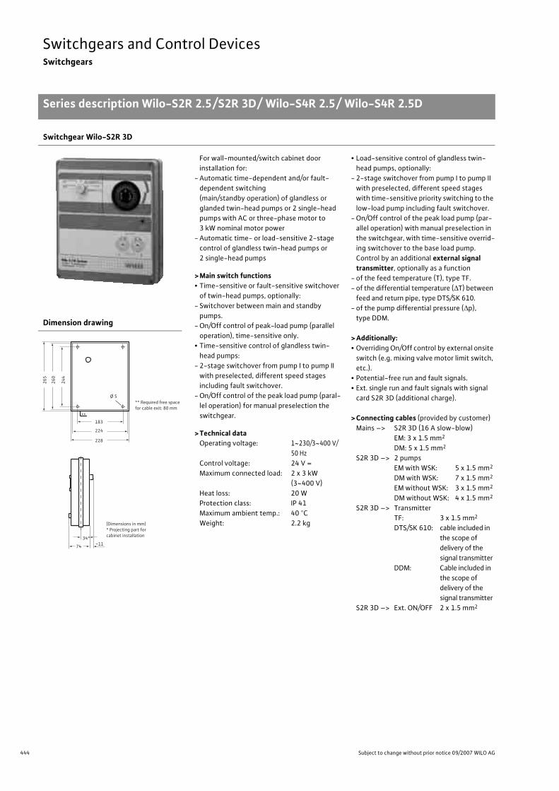
444 Subject to change without prior notice 09/2007 WILO AG
Switchgears and Control DevicesSwitchgears
Series description Wilo-S2R 2.5/S2R 3D/ Wilo-S4R 2.5/ Wilo-S4R 2.5D
Switchgear Wilo-S2R 3D
For wall-mounted/switch cabinet door installation for:
- Automatic time-dependent and/or fault-dependent switching(main/standby operation) of glandless or glanded twin-head pumps or 2 single-head pumps with AC or three-phase motor to 3 kW nominal motor power
- Automatic time- or load-sensitive 2-stage control of glandless twin-head pumps or 2 single-head pumps
> Main switch functions• Time-sensitive or fault-sensitive switchover
of twin-head pumps, optionally:- Switchover between main and standby
pumps.- On/Off control of peak-load pump (parallel
operation), time-sensitive only.• Time-sensitive control of glandless twin-
head pumps:- 2-stage switchover from pump I to pump II
with preselected, different speed stages including fault switchover.
- On/Off control of the peak load pump (paral-lel operation) for manual preselection the switchgear.
> Technical dataOperating voltage: 1~230/3~400 V/
50 HzControl voltage: 24 V =Maximum connected load: 2 x 3 kW
(3~400 V)Heat loss: 20 WProtection class: IP 41Maximum ambient temp.: 40 °CWeight: 2.2 kg
• Load-sensitive control of glandless twin-head pumps, optionally:
- 2-stage switchover from pump I to pump II with preselected, different speed stages with time-sensitive priority switching to the low-load pump including fault switchover.
- On/Off control of the peak load pump (par-allel operation) with manual preselection in the switchgear, with time-sensitive overrid-ing switchover to the base load pump.Control by an additional external signal transmitter, optionally as a function
- of the feed temperature (T), type TF.- of the differential temperature (�T) between
feed and return pipe, type DTS/SK 610.- of the pump differential pressure (�p),
type DDM.
> Additionally:• Overriding On/Off control by external onsite
switch (e.g. mixing valve motor limit switch, etc.).
• Potential-free run and fault signals.• Ext. single run and fault signals with signal
card S2R 3D (additional charge).
> Connecting cables (provided by customer)Mains –> S2R 3D (16 A slow-blow)
EM: 3 x 1.5 mm2
DM: 5 x 1.5 mm2
S2R 3D –> 2 pumpsEM with WSK: 5 x 1.5 mm2
DM with WSK: 7 x 1.5 mm2
EM without WSK: 3 x 1.5 mm2
DM without WSK: 4 x 1.5 mm2
S2R 3D –> TransmitterTF: 3 x 1.5 mm2
DTS/SK 610: cable included in the scope of delivery of the signal transmitter
DDM: Cable included in the scope of delivery of the signal transmitter
S2R 3D –> Ext. ON/OFF 2 x 1.5 mm2
Dimension drawing
Series descrip-tion Wilo-S2R 2.5/S2R 3D/ Wilo-S4R 2.5/ Wilo-S4R 2.5D
244
260
265
228
224
183
74 ~1134*
**
Ø 5** Required free space for cable exit: 80 mm
(Dimensions in mm)* Projecting part for cabinet installation

445
Switchgears and Control DevicesSwitchgears
Series description Wilo-S2R 2.5/S2R 3D/ Wilo-S4R 2.5/ Wilo-S4R 2.5D
Wilo Catalogue A1 - 50 Hz - Circulating Pumps in Glandless Design
Hea
ting,
Air-
cond
ition
ing,
Co
olin
gSe
cond
ary
Hot W
ater
Circ
ulat
ion
Sola
r The
rmal
, Geo
ther
mal
En
ergy
Sys
tem
sSe
rvic
e/Ac
cess
orie
s, S
yste
ms
Switc
hgea
rs a
nd C
ontr
ol D
evic
esPu
mp
Man
agem
ent S
yste
ms
Wilo signal cards SR for remote signal > SR signal cards for extending the internal equipment potential-free connections as per the table.Onsite wiring to a central monitoring station.Mounting of signal card in the SR unit in conjunction with a 10-pole flat plug.
> Technical dataContact rating: 250 V~/1 AConnection cable: maximum 100 m lengthCable cross-section: as required up to 1.5 mm2
Potential-free contacts S2R 2.5 S2R 3D S4R 2.5 S4R 2.5DCollective run signal SBM o • o –Collective fault signal SSM • • • •Individual run signal, pumps I + II – o – o
Single fault signal, pumps I + II – o – o
Speed-stage signal, operating pump o2 – o4 o4
• Series (included in the switchgear)o Signal card (functions on one card)

446 Subject to change without prior notice 09/2007 WILO AG
Switchgears and Control DevicesSwitchgears
Device allocation, equipment Wilo-S2R 2.5/S2R 3D, Wilo-S4R 2.5/ Wilo-S4R 2.5D
Device equipment
Single-head pump
Twin-head pump
Select between main/standby or peak-load
operation
Single-head pump
Twin-head pump
Select between main/standby or peak-load
operation
ON/OFF 2-stage 4-stage
Time-sensitive and/or
Tim
e-se
nsit
ive
for Z
-pum
p
Tim
e-se
nsit
ive
Diff
.-pr
essu
re d
epen
dent
�p
Tem
pera
ture
-dep
ende
nt T
Diff
.-te
mp.
-dep
ende
nt �
T
Diff
.-pr
essu
re d
epen
dent
�p
Tem
pera
ture
-dep
ende
nt T
Diff
.-Te
mp.
-dep
ende
nt �
T
Diff
.-pr
essu
re d
epen
dent
�p
Tem
pera
ture
-dep
ende
nt T
Diff
.-Te
mp.
-dep
ende
nt �
T
Diff
.-pr
essu
re d
epen
dent
�p
Tem
pera
ture
-dep
ende
nt T
Diff
.-Te
mp.
-dep
ende
nt �
T
Switching device S1R-h SK 601 S2R 2.5 S2R 3D S4R 2.5 S4R 2.5D
Auxiliary load module (optional – required for function)
�pMOD
T��TMOD
�p MOD
T��TMOD
o o o o o o
Auxiliary signal transmitter DDMo
TFo
DTSo
DDMo
TFo
DTSo
DDMo
DDMo
Motorallocation
AC current with built-in capacitor •AC current, blocking current-proof •AC current, WSK • 1) •Three-phase current, blocking cur-rent-proof • 1) •
Three-phase current, WSK, SSM • 1) • • • •Installation Wall-mounted installation, direct • • • • •
Cabinet-door installation • • • •Integrated pump installation – plug-in module •
Equipment
Main switch 0 – 1 •Selector switch – continuous •Pre-selector switch maximum speed stage
Control switch – 0 – Automatic • •Control switch II – I – 0 – Standby I/II –
Addition I + II • •
Clock timer with daily programme ON/OFF (1/4-hourly) • •Clock timer with daily programme Maximum/Min. or Automatic/Min. • • • •
Clock timer with daily/weekly programme and battery backup (120 hours) o o o o o o
Setpoint regulator 2) (�p – T – �T) in the scope of deliv-ery auxiliary module/transmitter • • • • • • • • • • • •
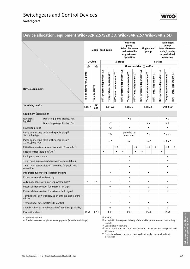
447
Switchgears and Control DevicesSwitchgears
Device allocation, equipment Wilo-S2R 2.5/S2R 3D, Wilo-S4R 2.5/ Wilo-S4R 2.5D
Wilo Catalogue A1 - 50 Hz - Circulating Pumps in Glandless Design
Hea
ting,
Air-
cond
ition
ing,
Co
olin
gSe
cond
ary
Hot W
ater
Circ
ulat
ion
Sola
r The
rmal
, Geo
ther
mal
En
ergy
Sys
tem
sSe
rvic
e/Ac
cess
orie
s, S
yste
ms
Switc
hgea
rs a
nd C
ontr
ol D
evic
esPu
mp
Man
agem
ent S
yste
ms
Equipment (continued)
Run signal light(s)
Operating-pump display…/pc. • 2 • 2
Operating-stage display…/pc. • 2 • 4 • 4
Fault signal light • 2 • • •Pump connecting cable with special plug 3)
3 m.../plug type • C provided bycustomer • C • 2 x C
Pump connecting cable with special plug 3)
10 m.../plug type o C – o C o 2 x C
Fitted temperature sensors each with 5 m cable 2) • 2 • 2 • 1 • 2 • 1 • 2
Fitted control cable 3 m/5m 2) • • • • • •Fault pump switchover • •Twin-head pump operation switchover switching • •Twin-head pump addition switching for peak-load operation • •
Integrated full motor protection tripping • • • •Excess current draw fault trip •Automatic reactivation after power failure4) • • • • • •Potential-free contact for external run signal o o o o
Potential-free contact for external fault signal • • • •Terminals for power supply to an external signal trans-mitter • •
Terminals for external ON/OFF control • • • •Signal card for external operation/speed-stage display o o o o
Protection class 5) IP 42 IP 31 IP 41 IP 41 IP 41 IP 41
• Standard versiono Special version or supplementary equipment (at additional charge)
1) + SK 6022) Included in the scope of delivery of the auxiliary transmitter or the auxiliary
module3) Special plug types Cor E4) Clock setting must be corrected in event of a power failure lasting more than
15 minutes5) Protection class of the entire switch cabinet applies to switch cabinet
installation
Device equipment
Single-head pump
Twin-head pump
Select between main/standby or peak-load
operation
Single-head pump
Twin-head pump
Select between main/standby or peak-load
operation
ON/OFF 2-stage 4-stage
Time-sensitive and/or
Tim
e-se
nsit
ive
for Z
-pum
p
Tim
e-se
nsit
ive
Diff
.-pr
essu
re d
epen
dent
�p
Tem
pera
ture
-dep
ende
nt T
Diff
.-te
mp.
-dep
ende
nt �
T
Diff
.-pr
essu
re d
epen
dent
�p
Tem
pera
ture
-dep
ende
nt T
Diff
.-Te
mp.
-dep
ende
nt �
T
Diff
.-pr
essu
re d
epen
dent
�p
Tem
pera
ture
-dep
ende
nt T
Diff
.-Te
mp.
-dep
ende
nt �
T
Diff
.-pr
essu
re d
epen
dent
�p
Tem
pera
ture
-dep
ende
nt T
Diff
.-Te
mp.
-dep
ende
nt �
T
Switching device S1R-h SK 601 S2R 2.5 S2R 3D S4R 2.5 S4R 2.5D

448 Subject to change without prior notice 09/2007 WILO AG
Switchgears and Control DevicesSwitchgears
Series description Wilo-SR-system, Wilo-SD-system
Switchgear series: Wilo-SD
Wall-mounted switchgear installation for automatic control of operating and standby pumps with glanded twin units.Automatic switchover from main pump to standby pump in the event of a fault and automatically time-sensitive by means of a day clock timer for regular switching of oper-ating and standby pumps. Additional manu-ally preselectable peak load operation by time-dependent switching of the 2nd pump on and off. With star/delta activation for connected load from 4 kW (for connected load up to 3 kW switchgear S2R 3D as described above). With motor protection switch or full thermistor protection starting with 11 kW .
> Main switch functions• Switchover from glanded pump twin-head
pumps or 2 single-head pumps.Optionally:
- Time-sensitive duty cycling from main to standby pump.
- Time-sensitive On/Off control of the peak load pump (parallel operation).
Short-time parallel operation during duty switchover is a feature in order to avoid the flap noise normally experienced on uncon-trolled pump performance switchover.
• Load-sensitive control of twin-head pumps and two single-head pumps
- Automatic On/Off control of the peak-load pump (parallel operation) by means of an additional signal transmitter, optionally as a function:- of the feed temperature (+T)
signal transmitter: TF.- of the differential temperature (�T)
between feed and return pipe,Signal transmitter: DTS/SK 610.
- of the pump differential pressure (�p),signal transmitter: DDM.
Time-sensitive switchover to the base load pump possible with manual switchgear preselection (setback opera-tion).
> Additional control function:Overriding On/Off control by onsite poten-tial-free switch (e.g. mixing valve motor limit switch, etc.)
> Connecting cablesS2R 3D –> as described aboveSD:SD –> mains
5-core(cross-section and fuse protec-tion pursuant to local regulations)
SD –> 2 pumps7-wire, starting with 11 kW addi-tional2 x 1.5 mm2 for full motor protec-tion (cross-section and fuse as per regional regulations)
SD –> transmitterTF: 3 x 1.5 mm2
DTS/SK 610: Cable included in the scope of deliv-ery of the signal transmitter
DDM: Cable included in the scope of deliv-ery of the signal transmitter
SD –> Ext. ON/OFF 2 x 1.5 mm2
Dimension drawing
Series descrip-tion Wilo-SR-sys-tem, Wilo-SD-sys-tem
CA
B
D
E
Ø d
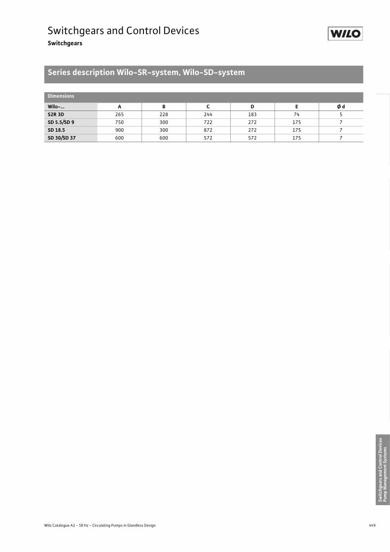
449
Switchgears and Control DevicesSwitchgears
Series description Wilo-SR-system, Wilo-SD-system
Wilo Catalogue A1 - 50 Hz - Circulating Pumps in Glandless Design
Hea
ting,
Air-
cond
ition
ing,
Co
olin
gSe
cond
ary
Hot W
ater
Circ
ulat
ion
Sola
r The
rmal
, Geo
ther
mal
En
ergy
Sys
tem
sSe
rvic
e/Ac
cess
orie
s, S
yste
ms
Switc
hgea
rs a
nd C
ontr
ol D
evic
esPu
mp
Man
agem
ent S
yste
ms
Dimensions
Wilo-... A B C D E Ø dS2R 3D 265 228 244 183 74 5SD 5.5/SD 9 750 300 722 272 175 7SD 18.5 900 300 872 272 175 7SD 30/SD 37 600 600 572 572 175 7

450 Subject to change without prior notice 09/2007 WILO AG
Switchgears and Control DevicesSwitchgears
Device allocation, equipment Wilo-S2R 3D/SD
Device allocation
Device equipment
Twin-head pump or 2 x single-head pumpMain/standby or peak-load operation
Time-sensitive and/or
Diff
eren
tial p
ress
ure-
depe
nden
t �p
Tem
pera
ture
-dep
ende
nt +
T
Diff
eren
tial t
empe
ratu
re-d
epen
dent
�T
Diff
eren
tial p
ress
ure-
depe
nden
t �p
Tem
pera
ture
-dep
ende
nt +
T
Diff
eren
tial t
empe
ratu
re-d
epen
dent
�T
Diff
eren
tial p
ress
ure-
depe
nden
t �p
Tem
pera
ture
-dep
ende
nt +
T
Diff
eren
tial t
empe
ratu
re-d
epen
dent
�T
Diff
eren
tial p
ress
ure-
depe
nden
t �p
Tem
pera
ture
-dep
ende
nt +
T
Diff
eren
tial t
empe
ratu
re-d
epen
dent
�T
Diff
eren
tial p
ress
ure-
depe
nden
t �p
Tem
pera
ture
-dep
ende
nt +
T
Diff
eren
tial t
empe
ratu
re-d
epen
dent
�T
Diff
eren
tial p
ress
ure-
depe
nden
t �p
Tem
pera
ture
-dep
ende
nt +
T
Diff
eren
tial t
empe
ratu
re-d
epen
dent
�T
Switching device S2R 3D SD 5.5 SD 9 SD 18.5 SD 30 SD 37
Auxiliary signal transmitter DDMo
TFo
DTSo
DDMo
TFo
DTSo
DDMo
TFo
DTSo
DDMo
TFo
DTSo
DDMo
TFo
DTSo
DDMo
TFo
DTSo
Motorallocation
Three-phase current P2 � 3 kW •Three-phase current P2 = 4 to 5.5 kW •
Three-phase current P2 = 7.5 to 9 kW •
Three-phase current P2 = 11 to 18.5 kW •
Three-phase current P2 = 22 to 30 kW •
Three-phase current P2 = 37 kW •
Installation Wall-mounted installation, direct • • • • •Cabinet-door installation •
Equipment
Control switch II – I – 0 – Standby I/II – Addition I + II • • • • • •
Clock timer with daily programme Maximum/Min. or Automatic/Min. • • • • • •
Clock timer with daily programme and battery backup (120 hours) o o o o o o
Clock timer with week programme and battery backup (120 hours) o o o o o o
Setpoint regulator 3) (�p – T – �T) in the scope of delivery auxiliary module/transmitter • • • • • • • • • • • • • • • • • •
Operation run signal light(s), operating-pump display…/pc. • 2 • 2 • 2 • 2 • 2 • 2
Fault signal light • • • • • •Pump connecting cable provided by
customerprovided by
customerprovided by
customerprovided by
customerprovided by
customerprovided by
customer
Activation type direct Y/� Y/� Y/� Y/� Y/�
Fitted temperature sensors each with 5 m cable 3) • 2 • 2 • 2 • 2 • 2 • 2
Fitted control cable 3 m/5m 3) • • • • • • • • • • • •

451
Switchgears and Control DevicesSwitchgears
Device allocation, equipment Wilo-S2R 3D/SD
Wilo Catalogue A1 - 50 Hz - Circulating Pumps in Glandless Design
Hea
ting,
Air-
cond
ition
ing,
Co
olin
gSe
cond
ary
Hot W
ater
Circ
ulat
ion
Sola
r The
rmal
, Geo
ther
mal
En
ergy
Sys
tem
sSe
rvic
e/Ac
cess
orie
s, S
yste
ms
Switc
hgea
rs a
nd C
ontr
ol D
evic
esPu
mp
Man
agem
ent S
yste
ms
Fault pump switchover • • • • • •Twin-head pump operation switchover switch-ing • • • • • •
Twin-head pump addition switching for peak-load operation • • • • • •
Integrated full motor protection tripping(starting with 11 kW thermistor) • • • •
Excess current draw fault trip • • •Setting range, motor protection switch (1 - 10) A (5.2 - 7.5) A (9.0 - 13.0) A
Automatic reactivation after power failure 2) • • • • • •Potential-free contact for external run signal • o o o o o
Potential-free contact for external fault signal • • • • • •Potential-free contacts for individual run and fault signals o o o o o o
Terminals for power supply to an external signal transmitter • • • • • •
Terminals for external ON/OFF control • • • • • •Protection class 1) IP 41 IP 54 IP 54 IP 54 IP 54 IP 54
• Standard versiono Special version or supplementary equipment (at additional charge)
1) Protection class of the entire switch cabinet applies to switch cabinet installation2) Clock setting must be corrected in event of a power failure lasting more than 15 minutes (standard version)3) Included in the scope of delivery of the auxiliary transmitter or the auxiliary module
Device allocation
Device equipment
Twin-head pump or 2 x single-head pumpMain/standby or peak-load operation
Time-sensitive and/or
Diff
eren
tial p
ress
ure-
depe
nden
t �p
Tem
pera
ture
-dep
ende
nt +
T
Diff
eren
tial t
empe
ratu
re-d
epen
dent
�T
Diff
eren
tial p
ress
ure-
depe
nden
t �p
Tem
pera
ture
-dep
ende
nt +
T
Diff
eren
tial t
empe
ratu
re-d
epen
dent
�T
Diff
eren
tial p
ress
ure-
depe
nden
t �p
Tem
pera
ture
-dep
ende
nt +
T
Diff
eren
tial t
empe
ratu
re-d
epen
dent
�T
Diff
eren
tial p
ress
ure-
depe
nden
t �p
Tem
pera
ture
-dep
ende
nt +
T
Diff
eren
tial t
empe
ratu
re-d
epen
dent
�T
Diff
eren
tial p
ress
ure-
depe
nden
t �p
Tem
pera
ture
-dep
ende
nt +
T
Diff
eren
tial t
empe
ratu
re-d
epen
dent
�T
Diff
eren
tial p
ress
ure-
depe
nden
t �p
Tem
pera
ture
-dep
ende
nt +
T
Diff
eren
tial t
empe
ratu
re-d
epen
dent
�T
Switching device S2R 3D SD 5.5 SD 9 SD 18.5 SD 30 SD 37
Auxiliary signal transmitter DDMo
TFo
DTSo
DDMo
TFo
DTSo
DDMo
TFo
DTSo
DDMo
TFo
DTSo
DDMo
TFo
DTSo
DDMo
TFo
DTSo

452 Subject to change without prior notice 09/2007 WILO AG
Switchgears and Control DevicesSwitchgears
Signal transmitter Wilo-TF, Wilo-DTS/SK 610, Wilo-DDM
Signal transmitter Wilo-TF Signal transmitter Wilo-DTS/SK 610 Signal transmitter Wilo-DDM
Pipe contact temperature sensor with tem-perature-dependent changeover contact for automatic switch-over of maximum/minimum speed stages with Wilo single- or twin-head pumps with multi-speed motors in conjunc-tion with the associated switchgears.
Electronic differential thermostat for differ-ential temperature-dependent switch-over of maximum/minimum speed stages with Wilo single-head or twin-head pumps with multi-speed motors in conjunction with the associated Wilo switchgears.
For wall-mounted installation as differential pressure contact pressure gauge. With adjustable switchpoints for automatic switch-over of maximum/minimum speed stages or of the maximum to minimum speed stages with Wilo single-head or twin-head pumps with multi-speed motors. Only in conjunction with the associated switchgears.Differential pressure switch with differential pressure display, adjustable maximum/mini-mum contacts, install pressure surge throt-tling, including 5 m shielded connection cable to the switchgear, 2 pieces cutting ring threads DIN 3862 ø 6 mm and 2 pieces cutting ring unions R 1�8 x ø 6 mm (pressure measuring lines and 3-way pressure-gauge cocks to be provided by customer).
> Technical dataMaximum supply voltage: 250 VMaximum switching capacity: 1 AProtection class: IP 54Maximum pressure rating: up to 16 barWeight: 1.7 kg
Pressure DDM 6: 0 to 0.6 barmeasurement DDM 10: 0 to 1.0 barranges: DDM 16: 0 to 1.6 bar
DDM 25: 0 to 2.5 bar
Temperature switch with selection button including 1 piece spring fastener for place-ment on tubes up to DN 50.
>Technical dataMaximum supply voltage: 250 VContacts: potential-free
changeover contactMaximum switching capacity: 3 AProtection class: IP 30Control range: +30 °C to +90 °CSwitching difference: 5 KWeight: 0.2 kg
Switchgear with selection button for differ-ential temperature, 3 m connection cable to the main switchgear, 2 pieces completely wired pipe contact sensor, each with 5 m cable and designation FLOW PIPE or RETURN and 4 pieces fastening straps for fixation to pipelines up to DN 100.
> Technical dataOperating voltage: 230 V/50 HzMaximum connected load: 0.1 kWProtection class: IP 54Differential temperaturerange: +4 °C to +90 °CWeight: 1.4 kg
Dimension drawing Dimension drawing Dimension drawing
Dimensions in mm Dimensions in mmFixation elements onsite
Dimensions in mmFixation elements onsite
Signal transmit-ter Wilo-TF, Wilo-DTS/SK 610, Wilo-DDM
Wilo pump
Connection cable foruse with S2R 2.5:with special plug included in scope ofdelivery; for use withS2R 3D: onsite
Cable connection to switch gear 3 x 1,5 mm2
Return
Return sensor
?
Feed
Feed sensor
Wilo pump
Connection cable for use with S2R 2.5: with special plug included in scope of delivery; for use with S2R 3D: onsite
1)Included in scope of delivery of the signal transmitter
Feed sensor cable1)
Return sensorcable1)
3 m cable forconnection to switch gear1) 6 x 0,75 mm.
DTS/SK 610 controllerShown as external sensor (iT)use together with Wilo switchgear
DDM
:
Pressure measuring lines 6 x 1 mm Cu (onsite)
Wilo single-head pump
Motor cable withspecial plug(scope of delivery ofthe Wilo switchgear)
1)Included in scope of delivery of the DDMPressure measuring lines and the three-way-gauge cocks must be available onsite
Elbow taper bush typepipe union R 1"x ø 6 mm1)
Elbow taper bushtype pipe union R 1" x ø 6 mm1)
2 pcs. taper bushtype screwedunions R 1" x ø 6 mm1)
5 m
shie
lded
cab
le 3
x 0
,75
mm
2 for c
onne
ctio
n to
switc
hgea
rs1
)
Shie
lded
cab
le fo
r ons
ite e
xten
sion
:to
100
m 3
x 1
,5 m
m2
; to
250
m 2
x 0
,75
mm
2

453
Switchgears and Control DevicesMotor protection
Wilo-SK 602, Wilo-SK 622, Wilo-C-SK
Wilo Catalogue A1 - 50 Hz - Circulating Pumps in Glandless Design
Hea
ting,
Air-
cond
ition
ing,
Co
olin
gSe
cond
ary
Hot W
ater
Circ
ulat
ion
Sola
r The
rmal
, Geo
ther
mal
En
ergy
Sys
tem
sSe
rvic
e/Ac
cess
orie
s, S
yste
ms
Switc
hgea
rs a
nd C
ontr
ol D
evic
esPu
mp
Man
agem
ent S
yste
ms
1) Wiring to indicator lights in switch cabinet door to be provided by customer.
Motor protection
Service life and operational reliability of a cir-culating pump depend to a great extent on the choice of the correct motor protection device.Motor protection switches can no longer be justified for utilisation in conjunction with multi-speed pumps due to the fact that their motors demonstrate different rated currents in the various speed stages and this requires correspondingly different types of fuse protection.
The motor fuse protection is secured with Wilo pumps as follows:
Blocking-current proof motor:no motor protection requiredThe pump motors are designed in such a way that current passing through the wind-ing cannot cause any damage in the event of overloading or blocking. This applies equally to single-phase and three-phase AC motors depending on the motor power rat-ings of the following pump series:
Pumps with full motor protection and Wilo relay SK 602/622/C-SK or Wilo Switch-gear/control deviceRealisation of full motor protection by means of thermal winding contacts (WSK) placed within the stator windings. This applies equally to single-phase and three-phase AC motors depending on the motor power ratings of the following pump series:
Series 1~ 3~ Series 1~ 3~Star-RS/-RSD P2 � 40 W – RP / P / DOP P2 � 50 WRP P2 � 20 W TOP-S/-SD
TOP-Z P2 � 180 W –TOP-S/-SDTOP-Z P2 � 90 W 1)
TOP-D 60 W � P2 � 320WTOP-D P2 � 20 W –
1) Internal protection against unacceptably high winding temperatures
Overview table Wilo motor protection relays
Relay Equipment Unit assembly Type of current
On/
Off
sw
itch
Term
inal
s fo
r rem
ote
On/
Off
sw
itchi
ng
Ope
rati
ng ru
n si
gnal
ligh
t
Faul
t sig
nal l
ight
Pote
ntia
l-fr
ee c
onta
cts
for e
xter
nal r
unsi
gnal
Pote
ntia
l-fr
ee c
onta
cts
for e
xter
nal f
ault
sig
nal
Pow
er c
onta
ctor
Sepa
rate
wal
l-m
ount
ed
inst
alla
tion
Alte
rnat
ive
switc
h ca
bine
t ins
talla
tion
1)
Term
inal
box
plug
-in
mod
ule
1~23
0 V
3~40
0 V
plus
ne
utra
l con
duct
or
3~40
0 V
with
out
neut
ral c
ondu
ctor
Wilo-C-SK • • • •Wilo-SK 602 • • • • • • •Wilo-SK 622 • • • • • • • • • • •
Relay Wilo-C-SK
Actuator plug-in module for plugging onto the motor connection box of Wilo gland-less circulating pumps with 4-stage three-phase motor1) and installed thermal wind-ing contacts (WSK) for monitoring the coil temperature (full motor protection).1) except for types P 65/250 r, P 80/250 r and P 100/200 r
Automatic reactivation of pump after power failure. After being tripped by full motor pro-tection, the motor remains deactivated until it is manually reset at the plug-in module.
C-SK versionContaining: contactors for full motor pro-tection tripping, an operation run signal light and reset button.
>Technical dataOperating voltage: 3~400 V without
neutral conductor (N)Frequency: 50 HzMaximum motor output P2 1.3 kW (4.4 A)Power loss: 0.8 WProtection class: IP 42Maximum media temp.: +110 °CMaximum ambient temp.: +40 °C
Motor pro-tectionWilo-SK 602, Wilo-SK 622, Wilo-C-SK
Cancel button

454 Subject to change without prior notice 09/2007 WILO AG
Switchgears and Control DevicesMotor protection
Series description Wilo-SK 602, Wilo-SK 622, Wilo-C-SK
Relay Wilo-SK 602/622
SK 602
SK 622
Wall-mounted unit for electrical connection of single-phase and three-phase AC pumps with integrated thermal winding contacts (WSK) for monitoring the winding temperature (full motor protection).Automatic reactivation of pump after power failure. After being tripped by full motor protection, the motor remains deactivated until it is manually reset.
> Device version SK 602Containing: contactors for full motor protec-tion tripping, ON/OFF switch, an operation run signal light, terminals for external poten-tial-free ON/OFF control and terminal rail.
> Device version SK 622As with SK 602, but also with potential-free contacts for external run and fault messages and fault signal light.
> Technical dataOperating voltage:SK 602/SK 622 1~230 V, 3~400 VFrequency: 50 HzMaximum motor power P2: 3 kWPower loss: 4 WProtection class: IP 31Maximum ambient temp.: +40 °CWeight: 0.25 kg
SK 6222 potential-free contactsMaximum contact load: 250 V/1 A/
150 VA eachRun signal: NO contactFault signal: NO contact
> Connecting cables (provided by customer)Connecting cable between SK and pumpAC (EM): 5 x 1.5 mm2
Three-phase (DM): 7 x 1.5 mm2
Dimension drawing
Dimensions in mmFixing sundries provided by customer
Series descrip-tion Wilo-SK 602, Wilo-SK 622, Wilo-C-SK
108
130
84 56
10
Ø 4

455
Switchgears and Control DevicesWilo Control System AS
Series description Wilo-AS 08 �P/AS 1.5 �P
Wilo Catalogue A1 - 50 Hz - Circulating Pumps in Glandless Design
Hea
ting,
Air-
cond
ition
ing,
Co
olin
gSe
cond
ary
Hot W
ater
Circ
ulat
ion
Sola
r The
rmal
, Geo
ther
mal
En
ergy
Sys
tem
sSe
rvic
e/Ac
cess
orie
s, S
yste
ms
Switc
hgea
rs a
nd C
ontr
ol D
evic
esPu
mp
Man
agem
ent S
yste
ms
Wilo-AS-system
Stageless control system with microproces-sor, differential pressure-sensitive, for the lower and median performance range on phase cut-in basis for glandless pumps (sin-gle-head and twin-head pumps) of all makes.
AS 08 �P• For single-phase and three-phase AC motors
with maximum current consumption I = A3
AS 1.5 �P• For three-phase AC motors with maximum
current consumption I = 6 A
Application• Differential pressure-sensitive perform-
ance control of glandless circulating pumps• Speed range between 100 % and 60 %• Simple installation: The control facility is
inserted into the electrical power wiring. Transmitter connections to pipework or to the pump
• Can be controlled externally by means of potential-free contacts
• Potential-free run and fault signal• Universal device for wall/switch cabinet
door installation (AS 1.5 �P only wall-mounted installation)
Main switch functions• Automatic, load-sensitive, stageless pump speed
control as a function of differential pressure (�p).• Random duty point adjustments by making
corrections at the signal transmitter or in the unit.
• Manual main switch switchover from control-led to mains operation.
• Overriding ON/OFF control by means of onsite external potential-free contact (e.g. SK clock timer 613 or mixing valve motor limit switch).
• Overriding MIN operation by means of exter-nal potential-free contact (e.g. SK clock timer 613 or mixing valve motor limit switch).
• Full motor protection with fault trip for pumps with integrated thermal winding contacts (WSK).
Standard equipment• Main switch Mains-Off regulation• Automatic reactivation after power failure• Short-circuit-proof due to integrated fuses• All control/transmitter inputs interference-
voltage-proof up to 400 V• Potential-free contacts for run and fault signal• Indicator lights:
Operation 1 pieceFault 1 pieceDifferential pressure too great 1 pieceDifferential pressure too low 1 piece
Functional sequenceDecreasing differential pressure will be responded to by increasing the motor speed until setpoint pressure is reached again. Rise of differential pressure will be counteracted by speed reduction until the set level is reached again. An external potential-free contact can be used to switch over to a fixed minimum speed (about 60 %).Note: Ideal for retrofitting all makes of
glandless pumps.
Connecting cables (provided by customer)Mains - switchgear: Minimum 5 x 1.5 mm2 with three-phase current, minimum 3 x 1.5 mm2 with alternating current.Switchgear - motor: Minimum 7 x 1.5 mm2 for three-phase pumps with thermal winding contact (WSK), minimum 5 x 1.5 mm2 for AC pumps with WSK, minimum 5 x 1.5 mm2 for three-phase pumps without WSK, minimum 3 x 1.5 mm2 for AC pumps without WSK.Switchgear transmitter (5 m cable included in the scope of delivery of the signal trans-mitter):DDS (up to 100 m): at least 2 x 1.5 mm2.Cable for ext. ON/OFF switch:(e.g. SK 613) 2 x 1.5 mm2, maximum cable length 100 m, contact open: pump stops.Cable for ext. Min. switch: (e.g. SK 613) 2 x 1.5 mm2, maximum cable length 100 m, contact open: pump runs at minimum speedConnecting cable for potential-free run/process signal: 2-core, cross-section as required (contact rating maximum 250 V/1 A/150 VA).Connecting cable for potential-free fault signal: 2-core, cross-section as required (contact rating maximum 250 V/1 A/150 VA).Twin-head pump operation possible with 2 AS units. Automatic, load-sensitive �p-regulation and fault-sensitive switcho-ver of twin-head pumps or 2 single-head pumps. Connecting cable: 3 x 0.75 mm2 or 2 x 0.75 mm2 shielded, maximum cable length 2 m.
Accessories (at additional charge)DDS differential pressure switchSK 613 switchgearControl card Wilo-AS (2–10 V) for installa-tion in AS device for remote adjustment of the �p setpoint. Required transmitter: DDG (4–20 mA) (also see: CR system accessories)

456 Subject to change without prior notice 09/2007 WILO AG
Switchgears and Control DevicesWilo Control System AS
Series description Wilo-AS 08 �P/AS 1.5 �P
Dimension drawing Technical data
Dimensions in mm AS 08 �P AS 1.5 �POperating voltage 1~230/3~400 V 3~400 VControl voltage 230 VFrequency 50 HzMaximum output current I 3 A 6 AMin. output power P2 75 W 500 WMaximum power loss 20 W 25 WProtection class IP 41Ambient temperature 0 to +40 °CMaximum back-up fuse 10 A (slow-blow)Weight 2.5 kg 3.5 kg
244
(360
)
260
(380
)
265
(384
)
228 (277)
224 (270)
183 (223)
74 ~1134
***
Ø 5
** Required clearance for cable outlet 80 mm
* Protruding part for cabinet installation (AS 08)
105 ~11
AS 08 AS 1.5
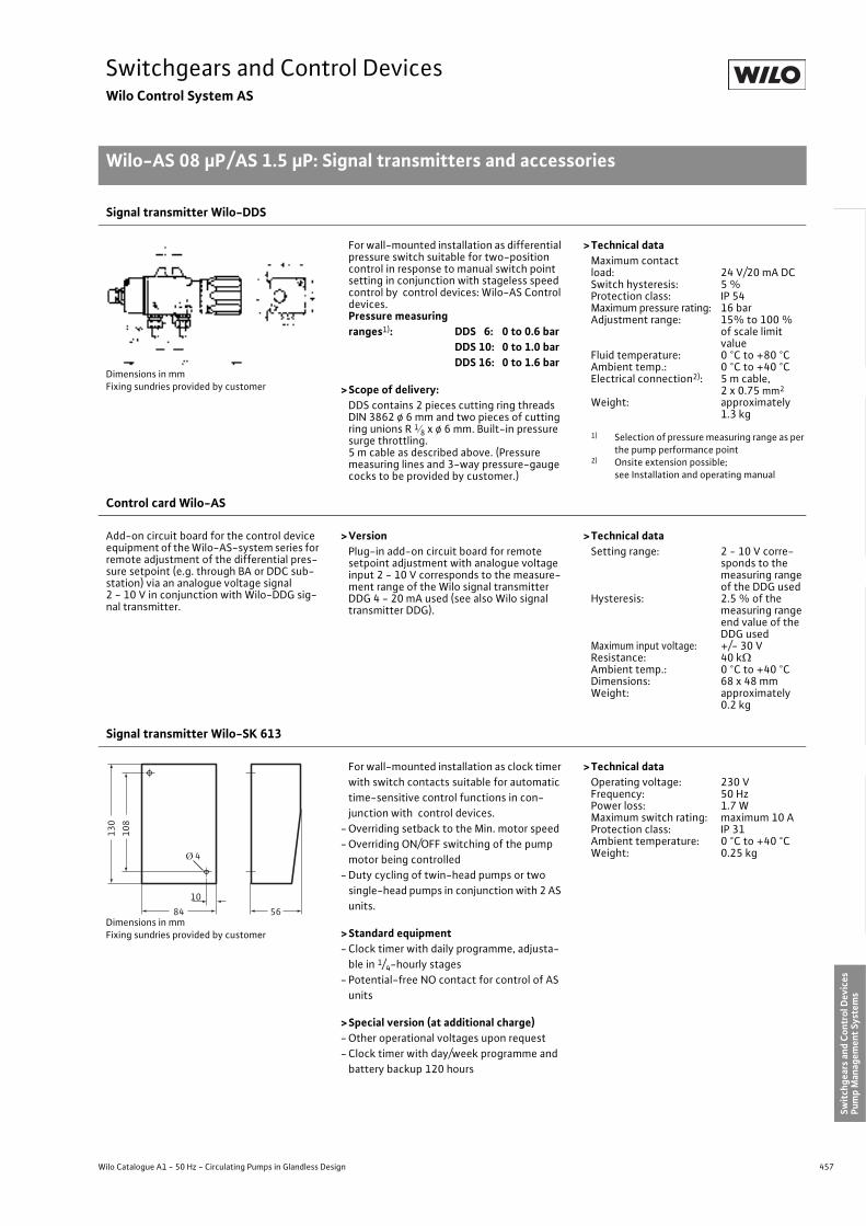
457
Switchgears and Control DevicesWilo Control System AS
Wilo-AS 08 �P/AS 1.5 �P: Signal transmitters and accessories
Wilo Catalogue A1 - 50 Hz - Circulating Pumps in Glandless Design
Hea
ting,
Air-
cond
ition
ing,
Co
olin
gSe
cond
ary
Hot W
ater
Circ
ulat
ion
Sola
r The
rmal
, Geo
ther
mal
En
ergy
Sys
tem
sSe
rvic
e/Ac
cess
orie
s, S
yste
ms
Switc
hgea
rs a
nd C
ontr
ol D
evic
esPu
mp
Man
agem
ent S
yste
ms
Signal transmitter Wilo-DDS
Dimensions in mmFixing sundries provided by customer
For wall-mounted installation as differential pressure switch suitable for two-position control in response to manual switch point setting in conjunction with stageless speed control by control devices: Wilo-AS Control devices.Pressure measuringranges1): DDS 6: 0 to 0.6 bar
DDS 10: 0 to 1.0 barDDS 16: 0 to 1.6 bar
>Scope of delivery:DDS contains 2 pieces cutting ring threads DIN 3862 ø 6 mm and two pieces of cutting ring unions R 1�8 x ø 6 mm. Built-in pressure surge throttling. 5 m cable as described above. (Pressure measuring lines and 3-way pressure-gauge cocks to be provided by customer.)
>Technical dataMaximum contactload: 24 V/20 mA DCSwitch hysteresis: 5 %Protection class: IP 54Maximum pressure rating: 16 barAdjustment range: 15% to 100 %
of scale limitvalue
Fluid temperature: 0 °C to +80 °CAmbient temp.: 0 °C to +40 °CElectrical connection2): 5 m cable,
2 x 0.75 mm2
Weight: approximately 1.3 kg
1) Selection of pressure measuring range as per the pump performance point
2) Onsite extension possible; see Installation and operating manual
Control card Wilo-AS
Add-on circuit board for the control device equipment of the Wilo-AS-system series for remote adjustment of the differential pres-sure setpoint (e.g. through BA or DDC sub-station) via an analogue voltage signal 2 - 10 V in conjunction with Wilo-DDG sig-nal transmitter.
>VersionPlug-in add-on circuit board for remote setpoint adjustment with analogue voltage input 2 - 10 V corresponds to the measure-ment range of the Wilo signal transmitter DDG 4 - 20 mA used (see also Wilo signal transmitter DDG).
>Technical dataSetting range: 2 - 10 V corre-
sponds to the measuring range of the DDG used
Hysteresis: 2.5 % of the measuring range end value of the DDG used
Maximum input voltage: +/- 30 VResistance: 40 k�Ambient temp.: 0 °C to +40 °CDimensions: 68 x 48 mmWeight: approximately
0.2 kg
Signal transmitter Wilo-SK 613
Dimensions in mmFixing sundries provided by customer
For wall-mounted installation as clock timer with switch contacts suitable for automatic time-sensitive control functions in con-junction with control devices.
- Overriding setback to the Min. motor speed- Overriding ON/OFF switching of the pump
motor being controlled- Duty cycling of twin-head pumps or two
single-head pumps in conjunction with 2 AS units.
>Standard equipment- Clock timer with daily programme, adjusta-
ble in 1/4-hourly stages- Potential-free NO contact for control of AS
units
>Special version (at additional charge)- Other operational voltages upon request- Clock timer with day/week programme and
battery backup 120 hours
>Technical dataOperating voltage: 230 VFrequency: 50 HzPower loss: 1.7 WMaximum switch rating: maximum 10 AProtection class: IP 31Ambient temperature: 0 °C to +40 °CWeight: 0.25 kg
108
130
84 56
10
Ø 4

458 Subject to change without prior notice 09/2007 WILO AG
Switchgears and Control DevicesWilo Control System AS
Wilo-AS 08 �P/AS 1.5 �P: Signal transmitters and accessories
Display unit for differential pressure Wilo-DDA
Dimensions in mmFixing sundries provided by customer
Wall-mounted gauge. Universal utilisation for optical head/pressure check procedure, measuring and testing in installations:
• Differential pressure readings between feed and return lines in heating systems
• Monitoring of heating circulating pumps • Monitoring of filters, compressors, fans, etc.• Checking transmission links:
measuring point – monitoring station – actuator – pump drive
Pressure measurement ranges:DDA 6: 0 to 0.6 barDDA 16: 0 to 1.6 barDDA 40: 0 to 4.0 bar
> Technical dataMaximum pressure rating: up to 25 barMeasuring accuracy: 2.5 % of upper limitAmbient temp.: -10 °C to +80 °CMedia temp.: 0 °C to +85 °CInstallation position: anyWeight: approximately
1.2 kg
Type bushtype pipeuniondia. 6 mm
ØØ

459
Switchgears and Control DevicesWilo-Vario- and Comfort control system VR, CRn, CR
Performance features
Wilo Catalogue A1 - 50 Hz - Circulating Pumps in Glandless Design
Hea
ting,
Air-
cond
ition
ing,
Co
olin
gSe
cond
ary
Hot W
ater
Circ
ulat
ion
Sola
r The
rmal
, Geo
ther
mal
En
ergy
Sys
tem
sSe
rvic
e/Ac
cess
orie
s, S
yste
ms
Switc
hgea
rs a
nd C
ontr
ol D
evic
esPu
mp
Man
agem
ent S
yste
ms
Wilo control device…
VR-HVAC CRn CR
Applications
Pump versions Glandless/ glanded pumps Glandless/ glanded pumps Glandless/ glanded pumps
Pump types Electronically controlled pumps Standard/Electronically controlled pumps
Standard Pumps
Number of pumps 1–4 1–6 1–6
Technical data
Complete device • Power supply for pumps required onsite •
Modular construction • • •Nominal power range P2 0.37–22.0 kW 1.1–200 kW 1.1–200 kW
Activation types Stageless analogue Stageless analogue/St.-Delta opt. Direct/St.-Delta
Electrical connection standard version 3~400 V, 50 Hz or
1~230 V, 50 Hz
1~230V, 50 HzPower connection of the pumps
onsite
3~400 V, 50 Hz
Protection class IP 54 IP 00 + IP 42 Standard /IP 54 optional
IP 00 + IP 42 standard/ IP 54 optional
Permitted ambient temperature 0 °C to +40 °C 0 °C to +40 °C 0 °C to +40 °C
Speed range Stageless analogue, 2–10 V, 3–10 V,
4–10 V preselectable, minimum speed of the pump
as per name plate up to 100 %
Between 40% and 100% of the nominal motor speed
Between 40% and 100% of the nominal motor speed
Control modes(description on the following pages)
�p-c • • •�p-c (TA) – • •�p-q (m³/ h) – • •�p-v • • •TA (outside temperature), controller – • •T-abs (process temp.), controller – • •TVL (feed temperature), controller – • •TRL (return temperature), controller – • •�T-c – • •�T-v – • •Manual control mode (DDC) – • •Q-c – • •
• = available, – = not available, o= optional on request
1) Larger number of pumps on request2) Higher rated motor power on request
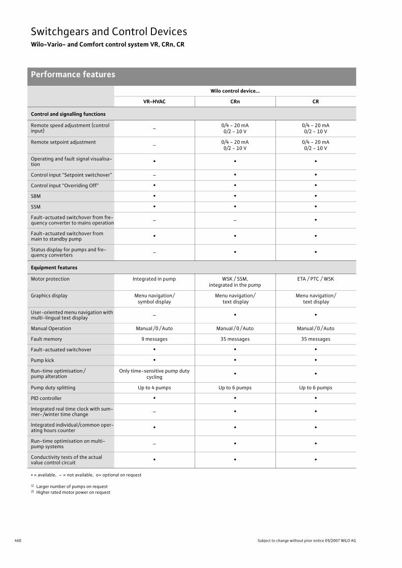
460 Subject to change without prior notice 09/2007 WILO AG
Switchgears and Control DevicesWilo-Vario- and Comfort control system VR, CRn, CR
Performance features
Control and signalling functions
Remote speed adjustment (control input) – 0/4 - 20 mA
0/2 - 10 V0/4 - 20 mA0/2 - 10 V
Remote setpoint adjustment – 0/4 - 20 mA0/2 - 10 V
0/4 - 20 mA0/2 - 10 V
Operating and fault signal visualisa-tion • • •
Control input “Setpoint switchover” – • •Control input “Overriding Off” • • •SBM • • •SSM • • •Fault-actuated switchover from fre-quency converter to mains operation – – •
Fault-actuated switchover from main to standby pump • • •
Status display for pumps and fre-quency converters – • •
Equipment features
Motor protection Integrated in pump WSK / SSM, integrated in the pump
ETA / PTC / WSK
Graphics display Menu navigation/symbol display
Menu navigation/text display
Menu navigation/text display
User-oriented menu navigation with multi-lingual text display – • •
Manual Operation Manual /0 / Auto Manual / 0 / Auto Manual / 0 / Auto
Fault memory 9 messages 35 messages 35 messages
Fault-actuated switchover • • •Pump kick • • •Run-time optimisation /pump alteration
Only time-sensitive pump duty cycling • •
Pump duty splitting Up to 4 pumps Up to 6 pumps Up to 6 pumps
PID controller • • •Integrated real time clock with sum-mer-/winter time change – • •
Integrated individual/common oper-ating hours counter • • •
Run-time optimisation on multi-pump systems – • •
Conductivity tests of the actual value control circuit • • •
Wilo control device…
VR-HVAC CRn CR
• = available, – = not available, o= optional on request
1) Larger number of pumps on request2) Higher rated motor power on request

461
Switchgears and Control DevicesWilo-Vario- and Comfort control system VR, CRn, CR
Performance features
Wilo Catalogue A1 - 50 Hz - Circulating Pumps in Glandless Design
Hea
ting,
Air-
cond
ition
ing,
Co
olin
gSe
cond
ary
Hot W
ater
Circ
ulat
ion
Sola
r The
rmal
, Geo
ther
mal
En
ergy
Sys
tem
sSe
rvic
e/Ac
cess
orie
s, S
yste
ms
Switc
hgea
rs a
nd C
ontr
ol D
evic
esPu
mp
Man
agem
ent S
yste
ms
Equipment features (continued)
“Mains - Emergency - Operation” service selector switch for mainte-nance purposes
– • •
Night reduction to minimum speed and/or second controlled level by means of internal clock timer
– • •
Remote confirmation of collective fault signal
– •(with DDC board)
•
Pilot pump function – • •Clock timer – • •
(with DDC board)
Switchover to a second setpoint level
– •(with DDC board)
•
Individual run and fault signals for pumps and converters
•(with options board)
•(with signal board)
•
Manual- / automatic switchover with external switch
– •(with control board)
•(with DDC board)
Connection option for a repair switch (potential-free contact)
– •(with control board)
•(with signal board)
Accessories
DDG differential-pressure sensor • • •(with control board)
Temperature boards KTY / PT 100 – • –
Temperature module PT 100 – – –
TSG temperature sensors – • •KTY outdoor temperature sensors – • •PT 100 outdoor temperature sensors – • •PTC fault trip – • •Control board – • –
(to be provided by the customer)
Signal board •(options board)
• •
DDC board – • •Volume flow transmitter –
(to be provided by the customer)–
(to be provided by the customer)•
Special features
DPM (dual pump management)
for DPM not required with: Stratos/-D /-Z/-ZD, TOP-E /-ED,
VeroLine IP-E, VeroTwin DP-E, CronoLine IL-E, CronoTwin DL-E
for DPM not required with: Stratos/-D /-Z/-ZD, TOP-E /-ED,
VeroLine IP-E, VeroTwin DP-E, CronoLine IL-E, CronoTwin DL-E
•
Wilo control device…
VR-HVAC CRn CR
• = available, – = not available, o= optional on request
1) Larger number of pumps on request2) Higher rated motor power on request

462 Subject to change without prior notice 09/2007 WILO AG
Switchgears and Control DevicesWilo-Vario- and Comfort control system VR, CRn, CR
Control modes
Differential pressure – constant (�p-c)
The differential pressure setpoint to be adjusted at the control devices is kept con-stant across the entire volume flow range. I.e., any reduction of flow volume (Q) due to throttling of the hydraulic regulating devices will in turn decrease the pump performance to match actual system demand by reducing the speed of the pump. A reduction in power consumption to less than 50 % of nominal power takes place parallel to the speed mod-ification. The application of differential-pressure control requires a variable flow vol-ume in the system.Peak-load operation, e. g. in conjunction with a twin-head pump, will be effected automatically and load-sensitively by the control system. If the capacity of the con-trolled base-load pump becomes insuffi-cient to cover the increasing load demand, the second pump will automatically be started to operate in parallel to cover the risen demand. The variable speed pump will then be run down until reaching the preset differential-pressure setpoint value.
> Required accessory:- Differential pressure sensor DDG
(also see Table “Performance features” pg. 459)
Fig.: Pump curve behaviour for stageless constant differential-pressure control (�p-c)
Δp-level = constant
Control range
Flow volume Q [%]
Q [%]
Del
iver
y he
adH
[%
] Po
wer
requ
irem
ent
[%]
Control / savings range
Flow volume
approx. ± 2 % Linearity/hysteresis

463
Switchgears and Control DevicesWilo-Vario- and Comfort control system VR, CRn, CR
Control modes
Wilo Catalogue A1 - 50 Hz - Circulating Pumps in Glandless Design
Hea
ting,
Air-
cond
ition
ing,
Co
olin
gSe
cond
ary
Hot W
ater
Circ
ulat
ion
Sola
r The
rmal
, Geo
ther
mal
En
ergy
Sys
tem
sSe
rvic
e/Ac
cess
orie
s, S
yste
ms
Switc
hgea
rs a
nd C
ontr
ol D
evic
esPu
mp
Man
agem
ent S
yste
ms
Index circuit evaluation
It is generally recommended to pick off the differential-pressure directly at the pump and to maintain it there at a constant level. An alternative would be to install the signal transmitter in the heating system as a remote signal transmitter in the so-called index circuit of the system (control-range extension). Operation with a remote signal transmitter will partly allow much larger speed reductions and thus pump perform-ance reductions. It is essential in this respect that the selected measuring point is valid for the consumption performance of all the system sections.In view of the fact that the index circuit can shift within the installation, optimisation can be carried out with the Wilo evaluator DDG. Measuring points ranging from 2 to 4 can be compared on a continuous basis. Only the lowest measured value forms the basis for the nominal / actual value comparison of the easy-to-use CC/CRn control device.
>Required accessory:- DDG differential-pressure sensor- Power supply unit DDG (for each DDG)- Impulse selector DDG (2 ...4 DDG)
(also see Table “Performance features” pg. 459)
Fig.: Block diagram for impulse-selector operation
DDG
DDG
DDG
DDG
*** Power cable min. 3 x 1,5 mm2
*** Sensor cable, shielded 3 x 1,5 mm2
*** Impulse selector cable, shielded 2 x 1,5 mm2
All cables onsiteFixing sundries and cable onsite
Mot
or c
able
, shi
eld
ed 7
x 1
,5 m
m2
Pow
er c
able
min
. 5
x ...
mm
2
cros
s-se
ctio
n ac
cord
ing
to lo
cal r
egul
atio
ns
Cab
le, s
hiel
ded
2 x
1,5
mm
2
Pow
er c
able
min
. 3 x
1,5
mm
2
DDG impulse selector
DDG transformer

464 Subject to change without prior notice 09/2007 WILO AG
Switchgears and Control DevicesWilo-Vario- and Comfort control system VR, CRn, CR
Control modes
Differential pressure – variable (�p-v)
When refurbishing or upgrading existing sys-tems it is not always possible to evaluate the point in the circuit which shows the lowest differential pressure. Original installations have been completed years ago and now, after installing thermostatic valves, noise problems have developed. The index circuit of the system is not known or it is not possi-ble to integrate new sensor connections.A control-range extension is nevertheless possible using the �p-v control mode (rec-ommended for single-pump systems). A processor unit of the control system adapts the differential-pressure setpoint value to a predetermined variable differential-pressure curve by means of setpoint /actual-value comparison. In duty/assist mode, the differential pressure is kept constant at the design level after the first peak-load pump has been cut in.
> Required accessory:- DDG differential-pressure sensor
(also see Table “Performance features” pg. 459)
Fig.: Pump curve behaviour for stageless variable differential-pressure control (�p-v)
Del
iver
y he
ad H
[m]
Pow
er r
equi
rem
ent
P [%
]
36
16
100
n = 60%
n = 40%
n = 100%
25
12
100
Δp = constant
Control range
Control range / savings potential
n = 100%
n = 40%
Q [%]
Q [%]
n = 60%
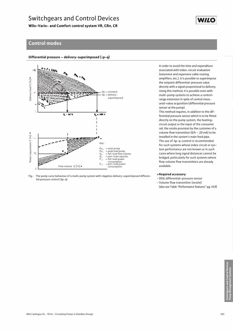
465
Switchgears and Control DevicesWilo-Vario- and Comfort control system VR, CRn, CR
Control modes
Wilo Catalogue A1 - 50 Hz - Circulating Pumps in Glandless Design
Hea
ting,
Air-
cond
ition
ing,
Co
olin
gSe
cond
ary
Hot W
ater
Circ
ulat
ion
Sola
r The
rmal
, Geo
ther
mal
En
ergy
Sys
tem
sSe
rvic
e/Ac
cess
orie
s, S
yste
ms
Switc
hgea
rs a
nd C
ontr
ol D
evic
esPu
mp
Man
agem
ent S
yste
ms
Differential pressure – delivery-superimposed (�p-q)
In order to avoid the time and expenditure associated with index-circuit evaluation (extensive and expensive cable routing, amplifiers, etc.), it is possible to superimpose the setpoint differential-pressure value directly with a signal proportional to delivery. Using this method, it is possible even with multi-pump systems to achieve a control-range extension in spite of central meas-ured-value acquisition (differential pressure sensor at the pump).This method requires, in addition to the dif-ferential pressure sensor which is to be fitted directly on the pump system, the heating-circuit output or the input of the consumer rail, the onsite provision by the customer of a volume flow transmitter (0/4 – 20 mA) to be installed in the system's main feed pipe.The use of �p-q-control is recommended for such systems whose index circuit or sys-tem performance are not known or in such cases where long signal distances cannot be bridged, particularly for such systems where flow volume flow transmitters are already available.
>Required accessory:- DDG differential-pressure sensor- Volume flow transmitter (onsite)
(also see Table “Performance features” pg. 459)
Fig.: The pump curve behaviour of a multi-pump system with stageless delivery-superimposed differen-tial pressure control (�p-q)
Del
iver
y he
adH
[%
] Po
wer
requ
irem
ent
P [%
]
Flow volume Q [%]
Dp = constantDp = delivery-
superimposed
Key:
Pu H = main pumpPu S = peak load pumpQ V = full-load flow volumeQ T = part-load capacityP 1V = full-load power
consumptionP 1T = part-load power
consumption

466 Subject to change without prior notice 09/2007 WILO AG
Switchgears and Control DevicesWilo-Vario- and Comfort control system VR, CRn, CR
Control modes
Differential pressure – temperature-superimposed (�p-T)
The operational performance of the hydrau-lic system can be further optimised by adapting the differential-pressure setpoint value for pump performance control as a function of a superimposed reference varia-ble (e.g. outdoor temperature).The setpoint differential-pressure value and thus the pump performance is reduced with rising outside temperatures, it will increase with falling outside temperatures.
> Required accessory:- DDG differential-pressure sensor- KTY 10 temperature board
or - PT 100 temperature board- CC temperature module PT 100
(also see Table “Performance features” pg. 459)- Process temperature sensors and outdoor
temperature sensors PT 100 or KTY
Fig.: Differential-pressure setpoint variation as a function of temperature
Temperature T[C]
Dif
fere
ntia
l pre
ssur
e se
tpoi
nt �
p [m
]
max.
min.
+ 50 - 20

467
Switchgears and Control DevicesWilo-Vario- and Comfort control system VR, CRn, CR
Control modes
Wilo Catalogue A1 - 50 Hz - Circulating Pumps in Glandless Design
Hea
ting,
Air-
cond
ition
ing,
Co
olin
gSe
cond
ary
Hot W
ater
Circ
ulat
ion
Sola
r The
rmal
, Geo
ther
mal
En
ergy
Sys
tem
sSe
rvic
e/Ac
cess
orie
s, S
yste
ms
Switc
hgea
rs a
nd C
ontr
ol D
evic
esPu
mp
Man
agem
ent S
yste
ms
Differential temperature control (�T)
Fig.: Flow volume-rate variation as a function of temperature spread
Heating / air-conditioning systems vary in terms of their cooling / heating require-ments with expectable outside tempera-ture fluctuations. A number of installations are based on constant volume circulation without fittings to regulate the flow volume (one-pipe systems, primary circuits, etc.). Moreover, pure throttling or bypass controls are highly uneconomical. Added to this comes the unnecessarily high power con-sumption (current) to drive the pump during low load periods.Differential-temperature control �T is one option of maintaining a constant difference between feed and return temperatures as a result of weather- and usage-related tem-perature spread. The heat flow becomes variable due to the changes in flow rates and the transferred heating/cooling capac-ity can be controlled independently of feed or return temperatures. Differential-tem-perature control should for reasons of com-prehensibility only be used with individual consumers or with systems with a known control-time constant.
>Required accessory:- KTY 10 temperature board
or - PT 100 temperature board- CC temperature module PT 100
(also see Table “Performance features” pg. 459)- Temperature sensor TSG or PT 100 (onsite)
Tem
pera
ture
T[C
]
Q [%]
Feed temperature
Return temperature
25
20
90
70
100
T
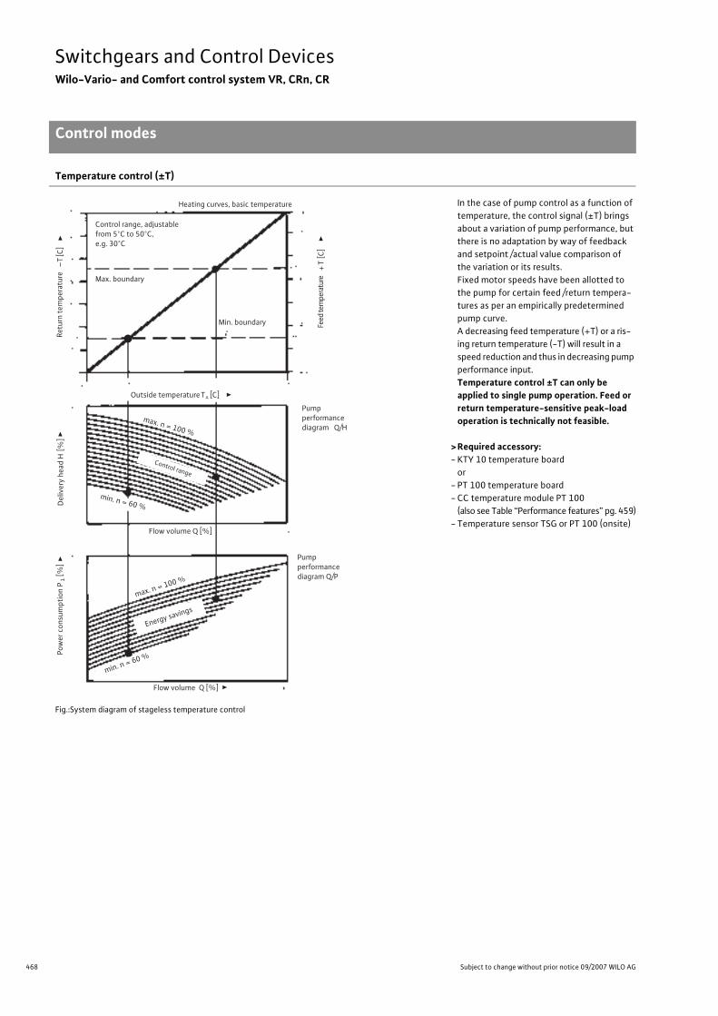
468 Subject to change without prior notice 09/2007 WILO AG
Switchgears and Control DevicesWilo-Vario- and Comfort control system VR, CRn, CR
Control modes
Temperature control (±T)
In the case of pump control as a function of temperature, the control signal (±T) brings about a variation of pump performance, but there is no adaptation by way of feedback and setpoint /actual value comparison of the variation or its results.Fixed motor speeds have been allotted to the pump for certain feed /return tempera-tures as per an empirically predetermined pump curve.A decreasing feed temperature (+T) or a ris-ing return temperature (-T) will result in a speed reduction and thus in decreasing pump performance input.Temperature control ±T can only be applied to single pump operation. Feed or return temperature-sensitive peak-load operation is technically not feasible.
> Required accessory:- KTY 10 temperature board
or - PT 100 temperature board- CC temperature module PT 100
(also see Table “Performance features” pg. 459)- Temperature sensor TSG or PT 100 (onsite)
Fig.:System diagram of stageless temperature control
Heating curves, basic temperature
Min. boundary
Del
iver
y he
ad
Pow
er c
onsu
mpt
ion
P1
[%]
Outside temperature
Pump performance diagram Q/H
Pump performance diagram Q/P
Flow volume Q [%]
Retu
rn te
mpe
ratu
re –T
[C]
H [
%]
Feed
tem
pera
ture
+T
[C]
TA [C]
Control range, adjustable from 5°C to 50°C, e.g. 30°C
Max. boundary
Flow volume Q [%]
Control range
max. n = 100 %
min. n = 60 %
max. n = 100 %
min. n = 60 %
Energy savings

469
Switchgears and Control DevicesWilo-Vario- and Comfort control system VR, CRn, CR
Control modes
Wilo Catalogue A1 - 50 Hz - Circulating Pumps in Glandless Design
Hea
ting,
Air-
cond
ition
ing,
Co
olin
gSe
cond
ary
Hot W
ater
Circ
ulat
ion
Sola
r The
rmal
, Geo
ther
mal
En
ergy
Sys
tem
sSe
rvic
e/Ac
cess
orie
s, S
yste
ms
Switc
hgea
rs a
nd C
ontr
ol D
evic
esPu
mp
Man
agem
ent S
yste
ms
Variable differential temperature (�T-v)
The �T-v control function is especially suit-able for pump performance control in one-pipe systems, district heating, systems with condensing boiler technology as well as cooling systems. The �T-v control mode ensures that the differential temperature is spread variably as a function of another temperature, e.g. the one outdoors. This allows that only the flow volume required for the heat transfer is circulated. This leads to significant energy savings on the drive side. Furthermore, the return temperature can be dramatically reduced. The broad temperature spread improves the efficiency of boilers or heat exchangers, and return temperature limits, as they are required e.g. in most district heating networks, can be achieved.
>Required accessory:- KTY 10 temperature board
or- PT 100 temperature board- CC temperature module PT 100
(also see Table “Performance features” pg. 459)- Temperature sensor TSG or PT 100 (onsite)- Process temperature sensors and outdoor
temperature sensors PT 100 or KTY
Fig.: Differential temperature as a function of the process- or outdoor temperature
Fig.: Impact on the differential temperature
Diff
eren
tial
tem
pera
ture
ΔT
[°K]
Outside, process temperature [°C]
ΔT
Feed temperature
Return temperature
Tmin Tmax
Outside, process temperature [°C]
Controller influence
negative positive
Diff
eren
tial
tem
pera
ture
– s
etpo
int
[°C
]

470 Subject to change without prior notice 09/2007 WILO AG
Switchgears and Control DevicesWilo-Vario- and Comfort control system VR, CRn, CR
Control modes
Constant flow volume control Q-c
The Q-c control function is sensibly applied in such cases where a constant, determinable flow volume is to be delivered. Such cases are for example cooling systems, cooling towers, test stands or systems for water supply, wastewater treatment and sewage disposal. Quantities from 2–2.000 m³ / h can be con-trolled.
> Examples for the application of flow rate controls:
- Mixing of chemically different well waters in an elevated tank for achieving a constant water quality
- Delivery of cold and cooling water as a func-tion of the connected cooling towers or consumers
- Mixing diverse sewage (municipal and industrial) for achieving a defined untreated sewage composition, adapted to the sew-age treatment in a sewage treatment plant
- Proportioning of chemicals in chemical and environmental engineering
- Agricultural irrigation
> Required accessory:- Flow rate meter onsite - Monitoring of limiting values is to be real-
ised onsite (system protection)
The flow volume which is set at the CR unit is kept constant. If the flow volume Q decreases, the speed of the pump system is increased until the set flow volume is covered again. If the flow volume increases, the speed is reduced so that only the required rate is delivered.
Fig.: Principle of the constant flow volume control
Pressure – constant (p-c)
The constant pressure (p-c) control mode is suitable for utilisation in conjunction with open pipe systems, e.g. water supply and pressure booster applications.Pump performance is adapted according to water demand (pressure-sensitive) along a setpoint level. Multi-pump operation fea-tures demand-sensitive On/Off control of base- and peak-load pumps. Problems of pressure surging originating from hunting between stop and start are fully eliminated.The deactivation of the base-load pump is effected by the control system when Q = 0 for a pressure boosting system.(also see Table “Performance features” pg. 459).
Fig.: Constant pressure control (p-c) depicted using a 3-pump system as an example
Qmin Qmax
Del
iver
y he
ad H
[m]
Delivery rate Q [m³]
Qset
De
live
ry h
ead
H [
m] Switch-off pressure level
peak-load pumppOff
Pipe network parabola
Set pointlevel
Pump 3Switch-onpressure levelpeak-load pump p On
Pump 1 Pump 2
Flow rate Q

471
Switchgears and Control DevicesWilo-Vario Control System VR-HVAC
Series description Wilo-VR-HVAC
Wilo Catalogue A1 - 50 Hz - Circulating Pumps in Glandless Design
Hea
ting,
Air-
cond
ition
ing,
Co
olin
gSe
cond
ary
Hot W
ater
Circ
ulat
ion
Sola
r The
rmal
, Geo
ther
mal
En
ergy
Sys
tem
sSe
rvic
e/Ac
cess
orie
s, S
yste
ms
Switc
hgea
rs a
nd C
ontr
ol D
evic
esPu
mp
Man
agem
ent S
yste
ms
Wilo-VR-HVAC-systemDigitally-controlled, stageless Vario control system for electroni-cally controlled glandless and glanded pumps of the Stratos, TOP-E, VeroLine-IP-E and CronoLine-IL-E series, for the mounting of single-pump and multiple-pump systems.
Typical field of application of the Wilo-VR-HVAC-systems is water circulation in heating, ventilation, cooling and air-conditioning sys-tems in larger-sized buildings such as hospitals, hotels, schools, department stores, industrial installations, residential, office and administration complexes.The most up-to-date of pumping technology and digital control electronics enable fulfilment of all the requirements demanded of the Wilo-VR-HVAC-system at the time of new installation and retrofit-ting:
- For all glandless and glanded pumps with integrated power electron-ics up to P2 = 22 kW nominal power.
- For pump splitting with up to 4 units (to utilise the lower-power indi-vidual units in low-load operation).
- Avoiding flow or cavitation noise.- Reduction of operating costs due to energy savings.
Principle of operationThe control device is responsible for controlling and regulating circu-lating pumps with electronic control or integrated pump performance electronics. The differential-pressure of a system is controlled as a function of the load with signal transmitters. The controller affects the frequency converter which has an impact on the pump speed. A modi-fication of the speed changes the delivery head and thus the power output of the single pumps. Depending on load-demand, pumps are activated or deactivated. The control device can control up to 4 pumps.
Equipment features- PID controller- Lockable main switch- Graphics LC display for displaying all values and operating states- Red-button technology (1-button operation)- LEDs for displaying operational readiness, operating pump(s), faulty
pump(s)- Circuit-breakers and output terminals for power supply of pump(s)- Integrated signal board (option)- Automatic pump alteration- Emergency operation as an option- Selection of a standby pump
Stageless speed controlAn electronic differential pressure sensor Wilo-DDG provides the dif-ferential pressure actual value as 4 - 20 mA current signal. Then the controller maintains the differential-pressure on a constant level by means of a setpoint / actual value comparison. If there is no “External Off”-signal and no fault, at least pump is run-ning. The pump speed here depends on the load. If the required out-put cannot be covered by this pump (base-load pump), another pump is activated, the speed of which is then, corresponding to the load consumption, controlled to the pressure setpoint. Pumps, which have been running already, keep operating at maximum speed (peak-load pumps). If demand decreases to such an extent that the control-ling pump runs in its lowest performance range and is not needed to cover demand, this pump will be deactivated and the control function is assigned to another pump which has previously been working at maximum speed.The control modes �p-c and �p-v can be preselected in the menu, only the first pump is controlled in �p-v mode, and if more pumps are activated, these will be controlled to the �p-c curve.
Control modesThe following control modes can be preselected for electronic per-formance control with the Wilo-VR-HVAC-system:
- For variable-delivery systems (e.g. heating systems with thermo-static valves):
- Constant differential-pressure control (�p-c)- Variable differential-pressure control (�p-v)
Control and signalling functionsThe Wilo-VR-HVAC-system provides extensive control inputs and outputs as standard equipment for integration in external monitoring units onsite:
- Analogue output �pout (0 - 10 VDC) for the outputting of the differ-ential pressure sensor actual value
- On/ / Off control by external potential-free contact- Collective fault signal SSM as potential-free switchover contact- Collective run signal SBM as potential-free switchover contact- Individual fault signal ESM for each pump as potential-free switcho-
ver contact (optional)- Individual run signal EBM as potential-free switchover contact
(optional)
Series descrip-tion Wilo-VR-HVAC

472 Subject to change without prior notice 09/2007 WILO AG
Switchgears and Control DevicesWilo-Vario Control System VR-HVAC
Series description Wilo-VR-HVAC
Dimensions, weights Wilo-VR-HVAC
Switch cabinet Dimensions (W x H x D)[mm]
Weight (without packaging)[kg]
VR-HVAC 1x0.37 WA 400 x 300 x 120 8.5
VR-HVAC 2x0.37 WA 400 x 300 x 120 9.0
VR-HVAC 3x0.37 WA 400 x 300 x 120 9.5
VR-HVAC 4x0.37 WA 400 x 300 x 120 10.0
VR-HVAC 1x0.55 WA 400 x 300 x 120 8.5
VR-HVAC 2x0.55 WA 400 x 300 x 120 9.0
VR-HVAC 3x0.55 WA 400 x 300 x 120 9.5
VR-HVAC 4x0.55 WA 400 x 300 x 120 10.0
VR-HVAC 1x0.75 WA 400 x 300 x 120 8.5
VR-HVAC 2x0.75 WA 400 x 300 x 120 9.0
VR-HVAC 3x0.75 WA 400 x 300 x 120 9.5
VR-HVAC 4x0.75 WA 400 x 300 x 120 10.0
VR-HVAC 1x1.1 WA 400 x 300 x 120 8.5
VR-HVAC 2x1.1 WA 400 x 300 x 120 9.0
VR-HVAC 3x1.1 WA 400 x 300 x 120 9.5
VR-HVAC 4x1.1 WA 400 x 300 x 120 10.0
VR-HVAC 1x1.5 WA 400 x 300 x 120 8.5
VR-HVAC 2x1.5 WA 400 x 300 x 120 9.0
VR-HVAC 3x1.5 WA 400 x 300 x 120 9.5
VR-HVAC 4x1.5 WA 400 x 300 x 120 10.0
VR-HVAC 1x2.2 WA 400 x 300 x 120 8.5
VR-HVAC 2x2.2 WA 400 x 300 x 120 9.0
VR-HVAC 3x2.2 WA 400 x 300 x 120 9.5
VR-HVAC 4x2.2 WA 400 x 300 x 120 10.0
VR-HVAC 1x3.0 WA 400 x 300 x 120 8.5
VR-HVAC 2x3.0 WA 400 x 300 x 120 9.0
VR-HVAC 3x3.0 WA 400 x 300 x 120 9.5
VR-HVAC 4x3.0 WA 400 x 300 x 120 10.0
VR-HVAC 1x4.0 WA 400 x 300 x 120 8.5
VR-HVAC 2x4.0 WA 400 x 300 x 120 9.0
VR-HVAC 3x4.0 WA 400 x 300 x 120 9.5
VR-HVAC 4x4.0 WA 400 x 300 x 120 10.0
VR-HVAC 1x5.5 WA 400 x 300 x 120 8.5
VR-HVAC 2x5.5 WA 400 x 300 x 120 9.0
VR-HVAC 3x5.5 WA 400 x 300 x 120 9.5
VR-HVAC 4x5.5 WA 400 x 300 x 120 10.0
VR-HVAC 1x7.5 WA 400 x 300 x 120 8.5
VR-HVAC 2x7.5 WA 400 x 300 x 120 9.0
VR-HVAC 3x7.5 WA 400 x 400 x 120 11.5
VR-HVAC 4x7.5 WA 400 x 400 x 120 12.0
VR-HVAC 1x11 WA 400 x 400 x 120 10.5
VR-HVAC 2x11 WA 400 x 400 x 120 11.0
VR-HVAC 3x11 WA 600 x 600 x 250 34.5
VR-HVAC 4x11 WA 600 x 600 x 250 35.0

473
Switchgears and Control DevicesWilo-Vario Control System VR-HVAC
Series description Wilo-VR-HVAC
Wilo Catalogue A1 - 50 Hz - Circulating Pumps in Glandless Design
Hea
ting,
Air-
cond
ition
ing,
Co
olin
gSe
cond
ary
Hot W
ater
Circ
ulat
ion
Sola
r The
rmal
, Geo
ther
mal
En
ergy
Sys
tem
sSe
rvic
e/Ac
cess
orie
s, S
yste
ms
Switc
hgea
rs a
nd C
ontr
ol D
evic
esPu
mp
Man
agem
ent S
yste
ms
VR-HVAC 1x15 WA 400 x 400 x 120 10.5
VR-HVAC 2x15 WA 400 x 400 x 120 11.0
VR-HVAC 3x15 WA 600 x 600 x 250 35.0
VR-HVAC 4x15 WA 600 x 600 x 250 35.5
VR-HVAC 1x18.5 WA 400 x 400 x 120 10.5
VR-HVAC 2x18.5 WA 400 x 400 x 120 11.0
VR-HVAC 3x18.5 WA 600 x 600 x 250 35.0
VR-HVAC 4x18.5 WA 600 x 600 x 250 35.5
VR-HVAC 1x22 WA 400 x 400 x 120 10.5
VR-HVAC 2x22 WA 400 x 400 x 120 11.0
VR-HVAC 3x22 WA 600 x 600 x 250 35.5
VR-HVAC 4x22 WA 600 x 600 x 250 36.0
Dimensions, weights Wilo-VR-HVAC
Switch cabinet Dimensions (W x H x D)[mm]
Weight (without packaging)[kg]

474 Subject to change without prior notice 09/2007 WILO AG
Switchgears and Control DevicesWilo-Vario Control System VR-HVAC
Terminal diagrams Wilo-VR-HVAC
Terminal diagram VR-HVAC 3~400 V Terminal diagram VR-HVAC 1~230 V
L1 L2 L3 PE
1 42...
1 42...
U V W PE
+24
V
SSM SBMExt.OFF
Sensor
IN
0...1
0 V
SSM
L1 N PE L1 N PE
1 42...
1 42...
+24
V
SSM SBMExt.OFF
Sensor
IN
0...1
0 V
SSM

475
Switchgears and Control DevicesWilo Comfort Control Systems CR, CRn
Series description Wilo-CR, Wilo-CRn
Wilo Catalogue A1 - 50 Hz - Circulating Pumps in Glandless Design
Hea
ting,
Air-
cond
ition
ing,
Co
olin
gSe
cond
ary
Hot W
ater
Circ
ulat
ion
Sola
r The
rmal
, Geo
ther
mal
En
ergy
Sys
tem
sSe
rvic
e/Ac
cess
orie
s, S
yste
ms
Switc
hgea
rs a
nd C
ontr
ol D
evic
esPu
mp
Man
agem
ent S
yste
ms
Wilo-Comfort Control Systems CR and CRnDigitally controlled, stageless Comfort-control systems for gland-less and glanded pumps of all makes, single and multi-pump sys-tems.CR version for conventional pumps with fixed speed.CRn version for stageless electronically controlled pumps or pumps with integrated frequency converter.
Fig.: Wilo-Comfort Control Device CR in heating/air-conditioning applications
Fig.: Wilo-Comfort Control Device CR in pressure boosting applications
Typical fields of application of the Wilo-Comfort Control Device are water circulation and water supply (e.g. pressure boosting)
- In residential, commercial and public buildings, hotels, hospitals, department stores and for industrial buildings.The most up-to-date of digital control electronics enables fulfilment of all the requirements demanded of the Wilo-Comfort Control Sys-tems at the time of new installation and retrofitting:
- With CR version for all glandless and glanded pumps with three-phase motor up to P2 = 30 kW nominal power (greater power outputs and other voltages on request)
- With CRn version power-independent via analogue control signals 0/2 – 10 V or 0/4 – 20 mA
- For pump splitting with up to 6 units (to utilise the lower-power indi-vidual units in low-load operation)
Abb.: System design, example of a one-pipe heating system with differential temperature control
- Avoidance of flow or cavitation noise- Lower operating costs due to energy savings- Speed control range between 100 % and 40 % of the nominal speed.
Principle of operationThe Wilo-Comfort Control Systems enable stageless electronic adjust-ment of pump power to the variable operating states of the hydraulic system, depending on the controlled variables of pressure (p), volume flow (Q), temperature (T).
Equipment features- PID controller- Integrated real-time clock with summertime- / wintertime switchover- Integrated individual / common operating hours counter- Run-time optimisation on multi-pump systems- Motor protection due to connection of WSK, KLF and TSA
(on CR version)- Motor protection due to connection of WSK and SSM (on CRn version)- Alphanumerical LCD display with the versions CR and CRn (4-line)
with backlight- Status display for drives
(e.g. pumps and frequency converters)- User-oriented menu navigation with multi-language clear-text dis-
play and/or symbol navigation- Data logging and detailed operating data display- Defined display of fault signals and history memory- Conductivity test of the transmitter paths
Sensor connection
DDG - or
TSG
Mains connectionMotor connection
Mains connect
Return Return sensor
Outside temperature sensor
Ext. offSSM0-10 Volt
6
Feed
Feed sensor
Mains supply connection
Mains supplyconnection

476 Subject to change without prior notice 09/2007 WILO AG
Switchgears and Control DevicesWilo Comfort Control Systems CR, CRn
Series description Wilo-CR, Wilo-CRn
Stageless speed controlStageless speed control must be regarded as the ideal solution to the problem of achieving 100% harmonious matching of pump perform-ance to the actual operating states of the system.Unfortunately, it is all but impossible to implement the special fea-ture it offers, namely the reduction of pump rotation speed to a very low amount – approximately 10–20 % residual speed, in everyday heating installation practice. Speed reductions in the range below 60% residual speed and the resulting drop in delivery head (delivery head as a quadratic function of speed) may result in malfunctions and sometimes to a breakdown in water distribution. In this case, the �p measuring point must be installed in the so-called index circuit of the system, i.e. the line or consumer with the greatest pressure losses. Thermal and mechanical overloading of the electro motors can occur at extremely low speeds below 40 % of the nominal speed.
Control modesThe following control modes can be preselected for electronic pump performance control with the Wilo-Comfort Control Systems (see also table “Performance features”, pg. 459):
• For variable-delivery systems (e.g. heating systems with thermo-static valves):
- Constant differential-pressure control (�p-c)- Variable differential-pressure control (�p-v)- Variable-delivery differential-pressure control (�p-q)- Temperature-superimposed differential-pressure control (�p-T)- Constant pressure control (p-c) for pressure boosting systems- Constant flow rate control (Q-c)• For constant-delivery systems
(e.g. cooling systems with heat exchangers):- Differential temperature control (�T)- Process-temperature control (±T)- Variable temperature control (�T-v)
Control and signalling functionsThe Wilo-Comfort Control Systems provide extensive control inputs and outputs as standard equipment for integration in external moni-toring units onsite (see also Table “Performance features” pg. 459):
- Remote setpoint adjustment (0 – 10 V/10 – 20 mA) preselectable (with CR and CRn)
- On/ Off control by external potential-free contact- Switching-on of frost protection by means of external potential-free
contact (only with heating / air-conditioning) via digital input- Low water cut-out switch by means of external potential-free con-
tact (only with pressure boosting) via digital input- Collective fault signal/collective run signal as potential-free change-
over contact- “Mains – Emergency – Operation” service selector switch for main-
tenance personnel- Switch-over to second setpoint level (with CR and CRn)
The following optional control inputs and outputs are available:- Remote confirmation of collective fault signal- Switchover to manual control mode- Individual run and fault signals for pumps and converters- Manual / automatic switch-over- Connection signalling contact of repair switches
Type key CR control device (Example CR 1.1 2 WA)
CR User-friendly regulation technology
1. Maximum rated motor output P2 of pump to be controlled in kW
2 Number of pumps to be controlled(1–6 pumps)
WA
Device version
WA = wall-mounted installation IP 42 (IP 54 on request)
SG = floor model IP 42 (IP 54 on request)
SE = control-panel installation
Type key CRn control system (example CRn 1-2 TP WA)
CRn User-friendly regulation technology new1-2 Number of connectable pumps:
1–23–45–6
TP, TK Control mode:T = temperature
P = sensor PT 100K = sensor KTY
WA
Device versionWA = wall-mounted installation IP 42
(IP 54 on request)SE = control-panel installation

477
Switchgears and Control DevicesWilo Comfort Control Systems CR, CRn
Technical data Wilo-CR, Wilo-CRn
Wilo Catalogue A1 - 50 Hz - Circulating Pumps in Glandless Design
Hea
ting,
Air-
cond
ition
ing,
Co
olin
gSe
cond
ary
Hot W
ater
Circ
ulat
ion
Sola
r The
rmal
, Geo
ther
mal
En
ergy
Sys
tem
sSe
rvic
e/Ac
cess
orie
s, S
yste
ms
Switc
hgea
rs a
nd C
ontr
ol D
evic
esPu
mp
Man
agem
ent S
yste
ms
Electrical data Wilo-Comfort Control System CRMain functionsAutomatic, load-sensitive, stageless speed control of glanded and glandless pumps with three-phase AC motors. For heating /air-conditioning as a function of differential-pressure �p, feed / return temperature (±T) or differential temperature (�T) including free adjustment of the duty point by means of advance cor-rection of full-load pump performance. For pressure boosting as a function of pressure (p).
Device version- Wall-mounted installation (WA) obtainable only up to 4 kW- Floor models (SG) obtainable starting from 5.5 kW- Control-panel installation (SE)
Electrical data Wilo-Comfort Control SystemMain functionsAutomatic-load-sensitive, stageless speed control of glanded and glandless pumps with integrated or external frequency converter. For heating/air-conditioning as a function of differential-pressure �p, feed / return temperature (±T) or differential temperature (�T) including free adjustment of the duty point by means of advance cor-rection of full-load pump performance by means of pre-correction of the full-load pump performance.
Device version- Wall-mounted installation- Control-panel installation
Power supply data Wilo-CR
Device classification:Maximum nominal motor power P2 [kW]3~400 V/ 50 Hz / 60 Hz
1.1 2.2 3.0 4.0 5.5 7.5 11.0 15.0 22.0 30.0
Maximum output current I [A] 2.8 5.6 7.6 9.7 13.0 16.0 24.0 32.0 44.0 61.0
Power factor cos > 0.9
Efficiency: – at Pmax– in permitted partial-load range
> 0.93> 0.85
Electrical connection 3~400 V/ N / 50 Hz / 60 Hz
Output voltage [V] 3 x 130 x V –400 V
Output frequency [Hz] (10 Hz) 12 Hz – 50 Hz / 60 Hz
Control range (% nominal motor speed) 40% – 100%
Permitted ambient temperature 0°C to +40°C
Power supply data Wilo-CRn
Electrical connection 1~230 V (shockproof plug) / N/ PE / 50 Hz / 60 HzPower connection of the pumps onsite
Output signals 0/2 – 10 V0/4 – 20 mA
Permitted ambient temperature 0°C to +40°C

478 Subject to change without prior notice 09/2007 WILO AG
Switchgears and Control DevicesWilo Comfort Control Systems CR, CRn
Technical data Wilo-CR, Wilo-CRn
Accessories for Wilo-Comfort Control SystemsAccessories
Sensor/transmitter
Differential pressure sensor DDG (4 – 20 mA) (observe measurement range) Terminal diagram:Base board CC / CRn system
Outdoor temperature sensor KTY or PT 100TSG temperature signal transmitter (included in the scope of delivery of the temperature board)
Terminal diagram:KTY 10 temperature board
Temperature boardAutomatic-stageless speed control as a function of the feed or return temperature or as a function of the tempera-ture differential between feed and return
Temperature board KTY 10: Heating systems with big differentials (T max: +140 °C, �T minimum � 10 K, �T maximum: 100 K), 2 temperature transmitters TSG included in scope of delivery
Terminal diagram:Temperature board KTY 10
PT 100: temperature board Cooling / air-conditioning systems with small differentials (T max: +140 °C, �T minimum � 5 K, �T maximum: 100 K)
Terminal diagram:PT 100 temperature board
CR-/CRn-control board
Shutdown of each pump (up to 2 pumps) by repair switch onsite and remote adjustment of operating mode (Mains / Automatic) for each pump (up to 2 pcs.) 3 control boards are required for 6 pumps
Terminal diagram:Control board
CR-/CRn-DDC board
Load adjustment of the pump system (setpoint-actual value comparison) via external controller, pump activation and deactivation, pump cycling, setpoint switchover, switch-over to remote speed control and acknowledgement of the collective fault signal via external potential-free contact
Terminal diagram:DDC board
CR/CRnsignal board 1 – 2
Potential-free individual operation signal / individual fault signal for pumps 1 – 2 and frequency converter, signalling of the conditions at digital inputs DIG2 or DIG3 (e.g. low water, antifreeze protection), speed-actual value and/or transmitter-actual value (preselectable)
Terminal diagram:Signal board 1-2
CR/CRnsignal board 3 – 6 Potential-free individual operation / individual fault signal for the pumps 3 – 6 Terminal diagram:
Signal board 3-6
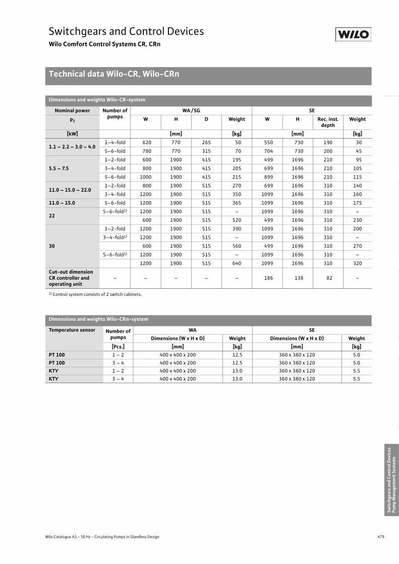
479
Switchgears and Control DevicesWilo Comfort Control Systems CR, CRn
Technical data Wilo-CR, Wilo-CRn
Wilo Catalogue A1 - 50 Hz - Circulating Pumps in Glandless Design
Hea
ting,
Air-
cond
ition
ing,
Co
olin
gSe
cond
ary
Hot W
ater
Circ
ulat
ion
Sola
r The
rmal
, Geo
ther
mal
En
ergy
Sys
tem
sSe
rvic
e/Ac
cess
orie
s, S
yste
ms
Switc
hgea
rs a
nd C
ontr
ol D
evic
esPu
mp
Man
agem
ent S
yste
ms
Dimensions and weights Wilo-CR-system
Nominal power Number of pumps
WA / SG SEp2 W H D Weight W H Rec. inst.
depthWeight
[kW] [mm] [kg] [mm] [kg]
1.1 – 2.2 – 3.0 – 4.01–4-fold 620 770 265 50 550 730 190 30
5–6-fold 780 770 315 70 704 730 200 45
5.5 – 7.51–2-fold 600 1900 415 195 499 1696 210 95
3–4-fold 800 1900 415 205 699 1696 210 105
5–6-fold 1000 1900 415 215 899 1696 210 115
11.0 – 15.0 – 22.01–2-fold 800 1900 515 270 699 1696 310 140
3–4-fold 1200 1900 515 350 1099 1696 310 160
11.0 – 15.0 5–6-fold 1200 1900 515 365 1099 1696 310 175
225–6-fold1) 1200 1900 515 – 1099 1696 310 –
600 1900 515 520 499 1696 310 230
30
1–2-fold 1200 1900 515 390 1099 1696 310 200
3–4-fold1) 1200 1900 515 – 1099 1696 310 –
600 1900 515 560 499 1696 310 270
5–6-fold1) 1200 1900 515 – 1099 1696 310 –
1200 1900 515 640 1099 1696 310 320
Cut-out dimension CR controller and operating unit
– – – – – 186 138 82 –
1) Control system consists of 2 switch cabinets.
Dimensions and weights Wilo-CRn-system
Temperature sensor Number of pumps
WA SEDimensions (W x H x D) Weight Dimensions (W x H x D) Weight
[Pcs.] [mm] [kg] [mm] [kg]PT 100 1 – 2 400 x 400 x 200 12.5 360 x 380 x 120 5.0PT 100 3 – 4 400 x 400 x 200 12.5 360 x 380 x 120 5.0KTY 1 – 2 400 x 400 x 200 13.0 360 x 380 x 120 5.5KTY 3 – 4 400 x 400 x 200 13.0 360 x 380 x 120 5.5

480 Subject to change without prior notice 09/2007 WILO AG
Switchgears and Control DevicesWilo-Comfort Control Systems CR, CRn
Terminal diagrams Wilo-CR, Wilo-CRn
Terminal diagram, CR System base board
Terminal diagram Drives CR-system (P2 � 4 kW) Terminal diagram Drives CR-system (P2 � 5.5 kW)
DDG1 2 3
Act
ual v
alue
Eart
hSe
nsor
Shie
ld
Sign
alEa
rth
Sens
orSh
ield
External setpoint
or actual value 2
Ext.off
MPI MPI
SSM SBM
Pot.-freemessages
P
J
Bridgeor
Ea
rth
Off
On
X1 9 10 11 12 13 14 15 16 17 18 19 20 21 22 23 24SSM SBMSensor Analog IN 1 Ext. off WM
Electroderelais
or
Frost-guard
or
Waterlevel-reglulator
X4 10 11 12 13 14 X5 15 16 17 18 19
U V W U V W
WSK WSK
Pump 1/3/5
Bridge or ther- mistor or
Pump 2/4/6
Bridge or ther- mistor or
Bridge
orTher-
mistor
or
WSK
X2 1 2
3 ~
X1 PE PE 1 2 3 PE PE 4 5 6 PE
102
U1V1W1
W2U2V2
Pump 1...6P = ...kWI = ...A

481
Switchgears and Control DevicesWilo-Comfort Control Systems CR, CRn
Terminal diagrams Wilo-CR, Wilo-CRn
Wilo Catalogue A1 - 50 Hz - Circulating Pumps in Glandless Design
Hea
ting,
Air-
cond
ition
ing,
Co
olin
gSe
cond
ary
Hot W
ater
Circ
ulat
ion
Sola
r The
rmal
, Geo
ther
mal
En
ergy
Sys
tem
sSe
rvic
e/Ac
cess
orie
s, S
yste
ms
Switc
hgea
rs a
nd C
ontr
ol D
evic
esPu
mp
Man
agem
ent S
yste
ms
Terminal diagram base board CRn System (for pump drives 1~230 V)
Terminal diagram expansion board CRn System (for pump drives 3~400 V)
421
Bridgeor
SSM
Pump 1...4P = ...kWI = ...A
TOP-E or
openor
WSKor
Pot.-freeNC contact
SSM Pump orStart relay
In0.......10V
Stratos0.......10V
1 ~M
L N PE
1)
On+ -
CR-IPG X3 / X4
CR-IPE X1 / X2
Required for Stratos IF-Modul with 0...10 V input(IF-Modul Stratos SBM, Stratos Ext. Min, Stratos Ext. Aus)
On-sitepower supply
Setpoint 1)
Bridgeor
SSM
orPump 1...6P = ...kWI = ...A
openor
Setpoint inputsof the pump,see table
WSK or
Pot.-freeNC contact
SSMPump or
Startrelayor
3 ~M
L1 L2 L3 PE
SetpointOn+ -
CR-IPG X3 / X4
CR-IPE X1 / X2
On-sitepower supply
Star-delta starter

482 Subject to change without prior notice 09/2007 WILO AG
Switchgears and Control DevicesWilo-Comfort Control Systems CR, CRn
Terminal diagrams Wilo-CR, Wilo-CRn
Wilo-CRn-system, allocation of the setpoint outputs: 1. at the control device CRn/2. at the pump to be regulated
Pump typeAnalogue control signal
1. Setpoint outlets CRn:+ -
2. Setpoint inputs pump:
IL-E...BF R1 (from date of manufacture 08/2002 to 02/2003) 0 - 10 V 2 4GND
IL-E...BF R1 (from date of manufacture 08/2002 to 02/2003) 0 - 20 mA 2 4GND
IL-E...BF R1 (from date of manufacture 03/2003) 0 - 10 V 2 7GND
IL-E...BF R1 (from date of manufacture 03/2003) 0 - 20 mA 2 7GND
IL-E... R1 (from date of manufacture 01/2003) 0 - 10 V 1 (0 - 10 V) 2 (GND)IL-E... R1 (from date of manufacture 01/2003) 0 - 20 mA 4 - 20 mA 2 (GND)IP-E 0 - 10 V 1 2IP-E 4 - 20 mA 1 2
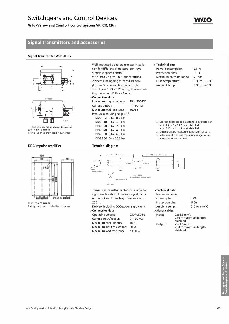
483
Switchgears and Control DevicesWilo-Vario- and Comfort control system VR, CR, CRn
Signal transmitters and accessories
Wilo Catalogue A1 - 50 Hz - Circulating Pumps in Glandless Design
Hea
ting,
Air-
cond
ition
ing,
Co
olin
gSe
cond
ary
Hot W
ater
Circ
ulat
ion
Sola
r The
rmal
, Geo
ther
mal
En
ergy
Sys
tem
sSe
rvic
e/Ac
cess
orie
s, S
yste
ms
Switc
hgea
rs a
nd C
ontr
ol D
evic
esPu
mp
Man
agem
ent S
yste
ms
Signal transmitter Wilo-DDG
(Dimensions in mm),Fixing sundries provided by customer
Wall-mounted signal transmitter installa-tion for differential pressure-sensitive stageless speed control.With installed pressure surge throttling, 2 pieces cutting ring threads DIN 3862 ø 6 mm, 5 m connection cable to the switchgear 1) (3 x 0.75 mm2), 2 pieces cut-ting ring unions R 1/8 x ø 6 mm.
>Connection dataMaximum supply voltage: 15 – 30 VDCCurrent output: 4 – 20 mAMaximum load resistance: 500 �Pressure measuring ranges:2) 3)
DDG 2: 0 to 0.2 barDDG 10: 0 to 1.0 barDDG 20: 0 to 2.0 barDDG 40: 0 to 4.0 barDDG 60: 0 to 6.0 barDDG 100: 0 to 10.0 bar
>Technical data Power consumption: 1.5 WProtection class: IP 54Maximum pressure rating: 25 barFluid temperature: 0 °C to +70 °CAmbient temp.: 0 °C to +40 °C
1) Greater distances to be extended by customerup to 25 m: 3 x 0.75 mm2, shielded up to 250 m: 3 x 1.5 mm2, shielded
2) Other pressure measuring ranges on request3) Selection of pressure measuring range to suit
pump performance point
DDG impulse amplifier Terminal diagram
(Dimensions in mm),Fixing sundries provided by customer
Transducer for wall-mounted installation for signal amplification of the Wilo signal trans-mitter DDG with line lengths in excess of 250 m.Delivery including DDG power supply unit.
>Connection dataOperating voltage: 230 V/50 HzCurrent input/output: 0 – 20 mAMaximum back-up fuse: 10 AMaximum input resistance: 50 �Maximum load resistance: � 600 �
>Technical dataMaximum powerconsumption: 5 VAProtection class: IP 54Ambient temp.: 0°C to +40°C
>Signal cables:Input: 2 x 1.5 mm2,
250 m maximum length,shielded
Output: 2 x 1.5 mm2. 750 m maximum length,shielded
Top view
DDG 10 to 100 (DDG 2 without illustration)
- +24V=
~
CR4-20 mA 4-20 mA
9 10
4 2
7 1
+
-
+
-
1
2
+
+
>
230V 50HzMeasuring transformer DDG
230V 50Hz
Transformer DDG
Wilo-signaltransmitter DDG
123
max. 250 m (2 x 1.5 mm2) max. 750 m (2 x 1.5 mm2)

484 Subject to change without prior notice 09/2007 WILO AG
Switchgears and Control DevicesWilo-Vario- and Comfort control system VR, CR, CRn
Signal transmitters and accessories
DDG impulse selector
Impulse selector (evaluator) for control-panel installation (rail mounting) for signal selection for two to four DDG measuring points.
> Connection dataOperating voltage: 230 V/ 50 HzCurrent input (2 to 4 x): 0 – 20 mACurrent output: 0 – 20 mAMaximum back-up fuse: 10 AMaximum input resistance: 50 �Maximum load resistance: � 1000 �
> Technical dataMaximum power consumption: 8 VAProtection class: IP 00Ambient temp.: 0°C to +40°C
> Signal cables:Per input: 2 x 1.5 mm2,
250 m maximum length,shielded
Per output: 2 x 1.5 mm2, 750 m maximum length,shielded
DDG power supply unit
Fixing sundries provided by customer
Wall-mounted power supply unit installa-tion for supplying power to the DDG signal transmitter in conjunction with the DDG impulse selector.
> Connection dataOperating voltage: 230 V/ 50 HzOutput voltage: 24 V DCOutput current: 0 – 20 mA
> Technical dataProtection class: IP 54Ambient temp.: 0°C to +40°C
TSG signal transmitter
Pipe-attached contact temperature sensor. Included in scope of delivery with KTY 10 temperature board.With 2 pieces spring fasteners for place-ment on the pipes up to DN 100, 1 tube thermal conduction paste, 5 m connection cable to the switchgear 1) (2 x 0.75 mm2, shielded).
> Connection dataKTY 10 PTC thermistor
- For +25°C: 2 k�- For +90°C: 3.09 k�
Maximum current: 2 mA
> Technical dataProtection class: IP 43Temp. range: 0°C to +150°C
1) Greater distances to be extended by customerup to 25 m: 3 x 0.75 mm2, shielded up to 100 m: 3 x 1.50 mm2, shielded up to 250 m: 3 x 2.50 mm2, shielded
70
15

485
Switchgears and Control DevicesWilo-Vario- and Comfort control system VR, CR, CRn
Signal transmitters and accessories
Wilo Catalogue A1 - 50 Hz - Circulating Pumps in Glandless Design
Hea
ting,
Air-
cond
ition
ing,
Co
olin
gSe
cond
ary
Hot W
ater
Circ
ulat
ion
Sola
r The
rmal
, Geo
ther
mal
En
ergy
Sys
tem
sSe
rvic
e/Ac
cess
orie
s, S
yste
ms
Switc
hgea
rs a
nd C
ontr
ol D
evic
esPu
mp
Man
agem
ent S
yste
ms
Outdoor temperature sensor KTY/ PT
Transmitter for wall mounting for outdoor temperature indication.
>Required accessory:- Connection line (onsite)
up to 25 m: 3 x 0.75 mm2, shieldedup to 100 m: 3 x 1.50 mm2, shieldedup to 250 m: 3 x 2.50 mm2, shielded
>Technical dataProtection class: IP 65Temp. range: –25 °C to +80°C
KTY 10 temperature board
Terminal diagram, KTY 10 temperature board
Add-on circuit board for the Wilo-CR/CRn-system switchgear series equipment when utilising the control modes
- Differential temperature control (�T)- Feed / return temperature control (±T)- Differential pressure – temperature-super-
imposed (�p-T)>Version
3 analogue inputs for TSG temperature sen-sors:
- Feed temperature (+T)- Return temperature (-T)- Temperature reference value (T)
Fixation material, CAN bus cable and 2 pcs. TSG temperature signal transmitters are included in the scope of delivery.
>Technical dataMeasuring range: ±T: - 20 ... +150 °C �T: � 10 KResolution: 10 bitsAccuracy: 0.2% of upper limit
+ transmitter toleranceAmbienttemperature: 0 °C to +40 °CDimensions: 100 mm x 120 mmWeight: approximately 0.5 kg
PT 100 temperature board
Terminal diagram, PT 100 temperature board
Add-on circuit board for the Wilo-CR/CRn-system switchgear series equipment when utilising the control modes
- Differential temperature control (�T)- Feed / return temperature control (±T)- Differential pressure – temperature-super-
imposed (�p-T)>Version
3 Analogue inputs for temperature sensor PT 100 in 2-/ 3- and 4-conductor technol-ogy to be provided by the customer:
- Feed temperature (+T)- Return temperature (-T)- Temperature reference value (T)
Fixing sundries and CAN-bus cable are included in the scope of delivery.
>Technical dataMeasuring range: ±T: - 20 ... +150 °C
�T: �5 KAccuracy: ± 2 K (in terms of standard
values as per DIN IEC 751)+ transmitter tolerance
Ambienttemperature: 0 °C to +40 °CDimensions: 100 mm x 120 mmWeight: approximately 0.5 kg
38
4,2
5365
35
50
M16
65
Feed
tem
pera
ture
Retu
rnte
mpe
ratu
re
Exte
rnal
tem
pera
ture
X3 1 2 3 4 5 6+ - + - + -
T (feed) T (return) T (external)
Feed
te
mpe
ratu
re
Retu
rn
tem
pera
ture
Exte
rnal
tem
pera
ture
X3 1 2 3 4 5 6 7 8 9
T (feed) T (return) T (process) + - + - + -
Two-wire circuit
Three-wire circuit

486 Subject to change without prior notice 09/2007 WILO AG
Switchgears and Control DevicesWilo-Vario- and Comfort control system VR, CR, CRn
Signal transmitters and accessories
DDC board
Terminal diagram, DDC board
Add-on circuit board for the Wilo-CR/CRn-system switchgear series equipment for remote control by means of external moni-toring units (e.g. BA or DDC substation)
> Version1 analogue input for external manipulated variable (speed adjustment with DDC oper-ation)8 digital inputs for connecting external potential-free probe for
- Peak-load cut-in- Peak-load deactivation- Pump duty cycling- Setpoint switchover- Confirmation of the collective fault signal- Parameter-record switchover- Control input 0/ 2 -10 V or 0 / 4 - 20 mA- Signal input DIG 3
Fixing sundries and CAN-bus cable are included in the scope of delivery.
> Technical dataAnalogue input: manipulated variableMeasuring range: 0 - 10 V,
0 / 4 - 20 mA( minimum - maxi-mum speed)
Input resistance: 10 k� or 50 �Resolution: 10 bitsAccuracy: 0.2 % of upper limit
+ transmitter toleranceDigital inputs:Input level: 24 VDC / 1 mADielectric strength: 250 VACMaximum cable length: 100 mTerminal cross-section: 1.5 mm2
Ambient temp.: 0 °C to +40 °CDimensions: 100 mm x 120 mmWeight: approximately 0.5 kg
Control board
Terminal diagram, control board
Add-on circuit board for the Wilo-CR/CRn-system switchgear series equipment for selecting between operating modes Manual – 0 – Automatic for a maximum of 2 pumps (e. g.: 5-pump system will require 3 pcs. control boards). Switch-over for each pump by means of potential-free control switches provided by the customer.
> FunctionManual – 0 – Automatic switch-over by means of potential-free two-way closers provided by the customer with middle posi-tion “Off” for each pump.Operating mode:
- Manual: pump in mains operation- 0: pump Off- Automatic: pump on standby for auto-
matically controlled opera-tion
Connection for customer-provided repair switches with auxiliary contact:
- closed: pump enabled- open: pump disabled
Fixing sundries and CAN-bus cable are included in the scope of delivery.
> Technical dataSelector switch: P1 / P2, P3 / P4,
P5 / P6Control inputs: 2 x repair switches
(On / Off for each pump)4 x control switches(Manual – 0 – Auto-matic for each pump)
Input level: 24 VDC / 1 mAVoltageresistance: 250 VACMaximum cable length: 100 mTerminalcross-section: 1.5 mm2
Ambient temp.: 0°C to +40°CDimensions: 100 mm x 120 mmWeight: approximately 0.5 kg
S1
0/4…20 mA
0…10 V
UI
SL- SL- PT SW External Param. Analogue ZU AB 1/2 Quit 2 IN 2
Peak
-loa
d cu
t-in
Peak
-loa
d de
acti
vati
on
Pum
p D
uty
Cyc
ling
Setp
oint
ch
ange
over
Exte
rnal
faul
t co
nfirm
atio
n
Cha
nge
of
para
met
er re
cord
Ana
logu
e, e
xter
nal
X3 1 2 3 4 5 6 7 8 9 10 11 12 13 14 15
1617
1819
In – +
DIG
.3Re
s.2
Pump 1/3/5 Pump 2/4/6
Pump 1/3/5 Pump 2/4/6
Man
ual
oper
atio
n
Rele
ase
Con
trol
func
tion
Man
ual
oper
atio
n
Rele
ase
Con
trol
func
tion
X3 1 2 3 4 5 6 7 8 9 10 11 12
Man
ual
Rele
ase
Con
trol
func
tion
Man
ual
Rele
sae
Con
trol
fu
ncti
on
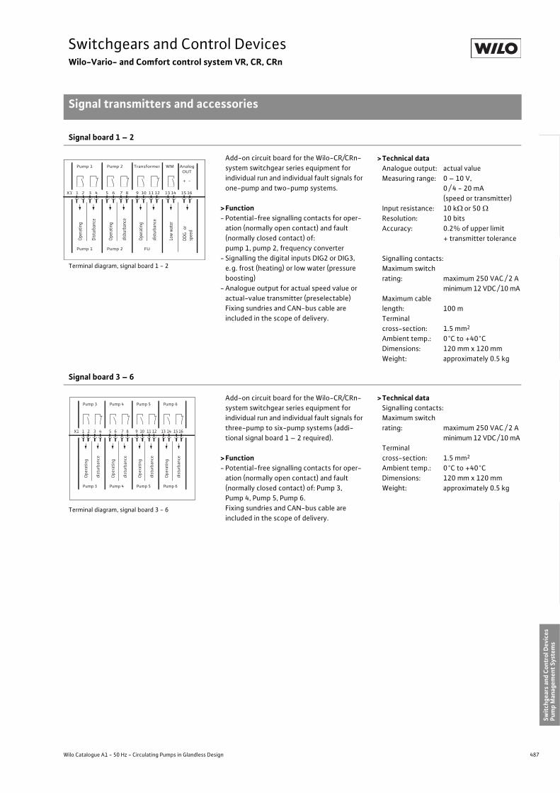
487
Switchgears and Control DevicesWilo-Vario- and Comfort control system VR, CR, CRn
Signal transmitters and accessories
Wilo Catalogue A1 - 50 Hz - Circulating Pumps in Glandless Design
Hea
ting,
Air-
cond
ition
ing,
Co
olin
gSe
cond
ary
Hot W
ater
Circ
ulat
ion
Sola
r The
rmal
, Geo
ther
mal
En
ergy
Sys
tem
sSe
rvic
e/Ac
cess
orie
s, S
yste
ms
Switc
hgea
rs a
nd C
ontr
ol D
evic
esPu
mp
Man
agem
ent S
yste
ms
Signal board 1 – 2
Terminal diagram, signal board 1 - 2
Add-on circuit board for the Wilo-CR/CRn-system switchgear series equipment for individual run and individual fault signals for one-pump and two-pump systems.
>Function- Potential-free signalling contacts for oper-
ation (normally open contact) and fault (normally closed contact) of:pump 1, pump 2, frequency converter
- Signalling the digital inputs DIG2 or DIG3, e.g. frost (heating) or low water (pressure boosting)
- Analogue output for actual speed value or actual-value transmitter (preselectable)Fixing sundries and CAN-bus cable are included in the scope of delivery.
>Technical dataAnalogue output: actual valueMeasuring range: 0 – 10 V,
0 / 4 - 20 mA(speed or transmitter)
Input resistance: 10 k� or 50 �Resolution: 10 bitsAccuracy: 0.2% of upper limit
+ transmitter tolerance
Signalling contacts:Maximum switch rating: maximum 250 VAC / 2 A
minimum 12 VDC /10 mAMaximum cable length: 100 mTerminal cross-section: 1.5 mm2
Ambient temp.: 0°C to +40°CDimensions: 120 mm x 120 mmWeight: approximately 0.5 kg
Signal board 3 – 6
Terminal diagram, signal board 3 - 6
Add-on circuit board for the Wilo-CR/CRn-system switchgear series equipment for individual run and individual fault signals for three-pump to six-pump systems (addi-tional signal board 1 – 2 required).
>Function- Potential-free signalling contacts for oper-
ation (normally open contact) and fault (normally closed contact) of: Pump 3, Pump 4, Pump 5, Pump 6.Fixing sundries and CAN-bus cable are included in the scope of delivery.
>Technical dataSignalling contacts:Maximum switch rating: maximum 250 VAC / 2 A
minimum 12 VDC /10 mATerminal cross-section: 1.5 mm2
Ambient temp.: 0°C to +40°CDimensions: 120 mm x 120 mmWeight: approximately 0.5 kg
Pump 1 Pump 2 Transformer WM Analog OUT
Pump 1 Pump 2 FU
Oper
atin
g
Dist
urba
nce
X1 1 2 3 4 5 6 7 8 9 10 11 12 13 14 15 16
Oper
atin
g
disb
urba
nce
Oper
atin
g
dist
urba
nce
Low
wat
er
+ - DD
G o
r sp
eed
Pump 3 Pump 4 Pump 5 Pump 6
Pump 3 Pump 4 Pump 5 Pump 6
Ope
rati
ng
dist
urba
nce
X1 1 2 3 4 5 6 7 8 9 10 11 12 13 14 15 16
Ope
rati
ng
dist
urba
nce
Ope
rati
ng
dist
urba
nce
Ope
rati
ng
dist
urba
nce
488 Subject to change without prior notice 09/2007 WILO AG
Switchgears and Control DevicesWilo-Vario- and Comfort control system VR, CR, CRn

489
Pump Management Systems Wilo-ControlContents
Wilo Catalogue A1 - 50 Hz - Circulating Pumps in Glandless Design
Hea
ting,
Air-
cond
ition
ing,
Co
olin
gSe
cond
ary
Hot W
ater
Circ
ulat
ion
Sola
r The
rmal
, Geo
ther
mal
En
ergy
Sys
tem
sSe
rvic
e/Ac
cess
orie
s, S
yste
ms
Switc
hgea
rs a
nd C
ontr
ol D
evic
esPu
mp
Man
agem
ent S
yste
ms
Pump management Wilo-Control
Series overview 490
Planning guide building automation 496
Pump control Wilo-IR-Module, Wilo-Dia-Log 500
Series description 500
Wilo-IR-Monitor 504
Series description 504
Wilo-IF-Module Stratos, Wilo-IF-Modules 506
Technical data 506
Function overview Wilo-Stratos pumpsWilo-IF-Modules Stratos 508
Function tables 508
Wilo-IF-Modules Stratos for single-head pumps 512
Wilo-IF-Modules Stratos for twin-head pumps 519
Function overview Wilo-TOP-E/-ED with Wilo-IF-Modules 526
Function tables 526
Wilo-IF-Modules for single-head pumps 530
Wilo-IF-Modules for twin-head pumps 533
Function overview Wilo-IP-E/IL-E and DP-E/DL-E with Wilo-IF-Modules 528
Function tables 528
Wilo-IF-Modules for single-head pumps 530
Wilo-IF-Modules for twin-head pumps 533
Wilo-Protect-Module 538
Function overview 538
Wilo-Protect-Module C for single-head pumps 540
Wilo-Protect-Module C for twin-head pumps 542
Building automation (BA) Wilo-Control AnaCon 546
Wilo-Control DigiCon 549
Wilo-Control DigiCon-A 550
Accessories Wilo-Control BusBox, CAN-Bus wire 552

490 Subject to change without prior notice 09/2007 WILO AG
Pump Management Systems Wilo-ControlPump control
Series overview interface modules
Converter modules Wilo-StratosWilo-IF-Module Stratos PLR
• Retrofittable plug-in module for pump types Wilo-Stratos/Stratos-Z/Stratos-D/Stratos-ZD• Serial digital PLR interface for connection to BA building automation via- Wilo interface converter or- Company-specific coupling modules• Communication-ready dual pump management (dependent on time, load and fault)
Wilo-IF-Module Stratos LON
• Retrofittable plug-in module for pump types Wilo-Stratos/Stratos-Z/Stratos-D/Stratos-ZD• Serial digital LON interface for connection to BA building automation via LONWorks networks:- LONTalk protocol- LONMark conformity• Communication-ready dual pump management (dependent on time, load and fault)
Wilo-IF-Module Stratos CAN
• Retrofittable plug-in module for pump types Wilo-Stratos/Stratos-Z/Stratos-D/Stratos-ZD• Serial, digital CAN interface for connection to a building automation BA via CAN bus system.• Protocol as per CANopen Standard• Communication-ready dual pump management (dependent on time, load and fault)
Wilo-IF-Module Stratos Ext. Off
• Retrofittable plug-in module for pump types Wilo-Stratos/Stratos-Z/Stratos-D/Stratos-ZD• Control input Overriding Off• Control input 0 - 10 V (remote speed or setpoint adjustment) for connection to BA building
automation• Communication-ready dual pump management (dependent on time, load and fault)
New!

491
Pump Management Systems Wilo-ControlPump control
Series overview interface modules
Wilo Catalogue A1 - 50 Hz - Circulating Pumps in Glandless Design
Hea
ting,
Air-
cond
ition
ing,
Co
olin
gSe
cond
ary
Hot W
ater
Circ
ulat
ion
Sola
r The
rmal
, Geo
ther
mal
En
ergy
Sys
tem
sSe
rvic
e/Ac
cess
orie
s, S
yste
ms
Switc
hgea
rs a
nd C
ontr
ol D
evic
esPu
mp
Man
agem
ent S
yste
ms
Wilo-IF-Module Stratos Ext. Min
• Retrofittable plug-in module for pump types Wilo-Stratos/Stratos-Z/Stratos-D/Stratos-ZD• Control input Overriding Min (setback operation without autopilot)• Control input 0 - 10 V (remote speed or setpoint adjustment) for connection to BA building
automation• Communication-ready dual pump management (dependent on time, load and fault)
Wilo-IF-Module Stratos SBM
• Retrofittable plug-in module for pump types Wilo-Stratos/Stratos-Z/Stratos-D/Stratos-ZD• Collective run signal • Control input 0 - 10 V (remote speed or setpoint adjustment) for connection to BA building
automation• Communication-ready dual pump management (dependent on time, load and fault)
Wilo-IF-Module Stratos Ext. Off/SBM
• Retrofittable plug-in module for pump types Wilo-Stratos/Stratos-Z/Stratos-D/Stratos-ZD• Control input Overriding Off• Collective run signal • Communication-ready dual pump management (dependent on time, load and fault)

492 Subject to change without prior notice 09/2007 WILO AG
Pump Management Systems Wilo-ControlPump control
Series overview interface modules
Interface converter modulesWilo-IF-Module
• Retrofittable plug-in module for pump types with IR interface- Wilo-TOP-E/ED- Wilo-VeroLine-IP-E- Wilo-VeroTwin-DP-E- Wilo-CronoLine-IL-E- Wilo-CronoTwin-DL-E• Serial digital PLR interface for connection to BA building automation via:- Wilo interface converters or- Company-specific coupling modules• Communication-ready dual pump management (dependent on time, load and fault, only
TOP-E/-ED and IL-E/DL-E)
Wilo-IF-Module LON
• Retrofittable plug-in module for LON-compatible pump types with infrared interface- Wilo-TOP-E/ED- Wilo-VeroLine-IP-E- Wilo-VeroTwin-DP-E- Wilo-CronoLine-IL-E- Wilo-CronoTwin-DL-E• Serial digital LON interface for connection to BA building automation via LONWorks networks:- LONTalk protocol- LONMark conformity• Communication-ready dual pump management (dependent on time, load and fault, only
TOP-E/-ED and IL-E/DL-E)
Wilo-IF-Module CAN
• Retrofittable plug-in module for pump types with IR interface- Wilo-VeroLine-IP-E- Wilo-VeroTwin-DP-E• Serial, digital CAN interface for connection to a building automation BA via CAN bus system.• Protocol as per CANopen Standard
New!

493
Pump Management Systems Wilo-ControlPump control
Series overview Operating and service units
Wilo Catalogue A1 - 50 Hz - Circulating Pumps in Glandless Design
Hea
ting,
Air-
cond
ition
ing,
Co
olin
gSe
cond
ary
Hot W
ater
Circ
ulat
ion
Sola
r The
rmal
, Geo
ther
mal
En
ergy
Sys
tem
sSe
rvic
e/Ac
cess
orie
s, S
yste
ms
Switc
hgea
rs a
nd C
ontr
ol D
evic
esPu
mp
Man
agem
ent S
yste
ms
Operating and service unitsWilo-IR-Module
• Remote control for electronically controlled Wilo pumps with infrared interface• Commissioning and diagnostic instrument/tool• Adaptable into the SDIO plug location of a Pocket-PC (PDA)• Wilo-Software compatible with Microsoft Windows mobile operating system• Extension of pump functions• Enables read-out, saving and printing of pump data sets
Wilo-Dia-Log
• Complete package for commissioning, service, maintenance and documentation of electroni-cally controlled Wilo pumps with infrared interface, consisting of:- Wilo-IR-Module- Pocket-PC- Portable printer- Accessories
Wilo-IR-Monitor
• Remote control for electronically controlled Wilo pumps with infrared interface• Commissioning and diagnostic instrument/tool• Extension of pump functions• Rotation test unit for all kinds of pumps and IEC standards motors
New!
New!

494 Subject to change without prior notice 09/2007 WILO AG
Pump Management Systems Wilo-ControlPump control
Series overview Wilo-Protect-Module
Wilo-Protect-ModuleWilo-Protect-Module C (single-head pumps)
• Plug-in module for single-head pumps of the Wilo-TOP-S/-Z as well as Wilo-TOP-RL and Wilo-SE series with mains connection 1~230 V, 50 Hz or 3~400 V, 50 Hz. Not suitable with controlled power supplies (e.g. Wilo-AS-system, Wilo-CC-system).
Wilo-Protect-Module C (twin-head pumps)
• Plug-in module for twin-head pumps of the Wilo-TOP-SD (2 pieces Wilo-Protect-Module C) and Wilo-SE-TW (2 pieces Wilo-Protect-Module C) series with mains connection 1~230 V, 50 Hz or 3~400 V, 50 Hz. Not suitable with controlled power supplies (e.g. Wilo-AS-system, Wilo-CC-system).

495
Pump Management Systems Wilo-ControlPump control
Series overview building automation
Wilo Catalogue A1 - 50 Hz - Circulating Pumps in Glandless Design
Hea
ting,
Air-
cond
ition
ing,
Co
olin
gSe
cond
ary
Hot W
ater
Circ
ulat
ion
Sola
r The
rmal
, Geo
ther
mal
En
ergy
Sys
tem
sSe
rvic
e/Ac
cess
orie
s, S
yste
ms
Switc
hgea
rs a
nd C
ontr
ol D
evic
esPu
mp
Man
agem
ent S
yste
ms
Building automation (BA)Series: Wilo-Control AnaCon
• Analogue interface converter for the universal connection of communication-ready Wilo pumps with serial, digital interface PLR to onsite monitoring units as per VDI 3814.
Series: Wilo-Control DigiCon
• Digital interface converter for the universal connection of communication-ready Wilo pumps with serial, digital interface PLR to onsite monitoring units with digital interface RS 485.
Series: Wilo-Control DigiCon-A (manual operation level)
• Manual operation level for Wilo-Control DigiCon for expanded connection of communication-ready Wilo pumps with serial, digital interface PLR to onsite operation levels as per VDI 3814.The Wilo-Control DigiCon-A manual operation level makes possible the overriding control of pumps which are connected to Wilo-Control DigiCon interface converters.
Series: Wilo-Control BusBox
• Junction box for mounting a CAN bus system with short spur lines for linking up the nodesNew!

496 Subject to change without prior notice 09/2007 WILO AG
Pump Management Systems Wilo-ControlPump control
Planning guide building automation
Building automation (BA)Automatically controlled processes have become vitally important in advanced building services technology. This particularly applies to all building and mechanical services in the areas of:
- Heating systems- Cooling systems- Ventilation systems- Heat pump installations- Combined heat and power plants - Water Supply- Drainage, sewage disposal
The BA has the task of controlling the dependencies between the different trades involved in the technical building equipment (TGA). It is in particular the facility management that requires the intersec-tional exchange of information and data in order to run the building or estates with optimum efficiency and economy. As field devices, pumps are to be seen as components indispensable for operations in the TGA that utilise high power consumption. Operational reliability and economic efficiency of pumps and pump systems are guaranteed to the greatest possible extent by central availability and monitoring of these pumps and pump systems.Due to the rapid technical advances made in the areas of electrical engineering/electronics, potential-free contacts and analogue unit signals are being successively superseded by bus systems.
Fig.: Building automation - schematic diagram
M M MM
Operating station /
operating unit
Network
Net
wor
k
Network
Network
Programmingunit
Data interfaceunit
Data processingapparatus /
server station
Operating unit Communications unit / controller /
ASR
Application-specificcontrol and
regulatory unit
Controller / automation station /
ASR
Data interfaceunit
Systemfor special
applications
Systemfor special
applications
Programmingunit
Operating station /
operating unit
Data interfaceunit
Space / operating unit
Local overridingoperating units
Systemfor special
applications
Aut
omat
ion
Man
agem
ent
Fiel
d
Venetian blinds / protection against sunlight
Light / dimming
Connections within the functional levels
Connections between the functional levels

497
Pump Management Systems Wilo-ControlPump control
Planning guide building automation
Wilo Catalogue A1 - 50 Hz - Circulating Pumps in Glandless Design
Hea
ting,
Air-
cond
ition
ing,
Co
olin
gSe
cond
ary
Hot W
ater
Circ
ulat
ion
Sola
r The
rmal
, Geo
ther
mal
En
ergy
Sys
tem
sSe
rvic
e/Ac
cess
orie
s, S
yste
ms
Switc
hgea
rs a
nd C
ontr
ol D
evic
esPu
mp
Man
agem
ent S
yste
ms
Integration in BADifferent communication connections, depending on the kind and extent of a BA system, are required to communicate with signals, commands or data exchange.In Germany, design and functions of BA systems are precisely defined in standard specification VDI 3814. The scope of communication is crucial in determining whether potential-free contacts and analogue signals (2 control cables are required for each kind of information) or intelligent bus systems (all data via a bus line) are used for data trans-mission.Control terminals at which signals are available via internal relays are on hand with Wilo pumps and with possible accessories in accordance with VDI 3814.
Principle of operation:
It is also possible to effect external control functions such as Overrid-ing Off and Overriding Min. by means of customer-provided poten-tial-free contacts, offering the following combinations:
• Overriding Off:- Stratos/Stratos-Z/Stratos-D/Stratos-ZD with IF-Modules- TOP-E/-ED (P2 � 350 W)- CronoLine-IL-E/CronoTwin-DL-E- VeroLine-IP-E/VeroTwin-DP-E• Overriding Min.:- Stratos/Stratos-Z/Stratos-D/Stratos-ZD with IF-Modules• Overriding Off, Overriding Maximum and Overriding Min:- Stratos/Stratos-Z/Stratos-D/Stratos-ZD with Stratos IF-Modules PLR
and analogue interface converter- TOP-E/-ED with IF-Modules PLR and Wilo-Control AnaCon- VeroLine-IP-E/VeroTwin-DP-E with IF-Module PLR and Wilo-Control
AnaCon- CronoLine-IL-E/CronoTwin-DL-E with IF-Modules PLR and Wilo-
Control AnaCon
In addition to these functions the new pumps with communication capabilities feature the option of logging an extensive number of physical actual data. The latest sensor technology records hydraulic and electrical pump data and makes them available via a PLR or LON serial digital interface of the BA. All of this information can be exchanged between a communication-ready pump (Accessories modules required) and another BA unit with a 2-wire cable. Pumps with communication capability are:
• Stratos/Stratos-Z/Stratos-D with IF-Modules• TOP-E/-ED with IF-Modules• CronoLine-IL-E/CronoTwin-DL-E with IF-Modules• VeroLine-IP-E/VeroTwin-DP-E with IF-Modules
Systems integrationThe demands made of communication capabilities and functionality are guided through ever more complex hierarchies of building auto-mation as a result of the rising demands made of mechanical services equipment (TGA - also referred to as technical building equipment) in large building projects. This leads to a situation where components at the field level are becoming increasingly technically sophisticated, because - among other things - they also fulfil functional needs at the automation level. In order to lower installation costs and thus investment costs of technical building equipment, and thus also those associated with pump systems, while at the same time increas-ing their economic efficiency and reliability, it is necessary to use sys-tems with “open communication” and “distributed intelligence”. The automation and control system Wilo-Control offers:
• Monitoring and control as per 3814 with- potential-free contacts- analogue signals
• Serial, digital interface PLR (Wilo-specific hardware and protocol) of the communication-ready pumps is connected via a 2-wire line in star formation to a Wilo interface converter or a company-specific coupling module (I/O module). This connection permits transmission links of up to 200 m. Additional advantages are:
- Locking protection- Immunity to interference- Small cross-sections (0.75 mm2)- ECM-protected at both ends- Galvanically isolated- Interference-voltage-proof to 250 VAC
• Serial, bus-ready Interface RS 485 (hardware standard, protocol Wilo-specific) with the digital interface converter for communication with digital monitoring units. The data protocol is to be co-ordinated with respective BA manufacturer.
• Serial, bus-ready Interface LON with LONTalk protocol and trans-ceiver type FTT10A for connection with electronically controlled LON compatible Wilo pumps with infrared interface to LONWorks net-works. The LONWorks technology offers installation advantages such as:
- Locking protection- Immunity to interference- Small cross-sections (0.75 mm2)- Shielded cable not required- ECM-protected at both ends- Galvanically isolated
Mains voltage Control input “Overriding Off”
Signalling relaySBM SSM
Off 1) 0 0On closed
open10
00
On;Pump faulty
closedopen
00
11
0 = relay inactive SBM = collective run signal1 = relay active SSM = collective fault signal1) Mains voltage “Off” = complete electronics breakdown
Input NO contact SPDT contact
Fault signal in compliance
with VDI 3814
Run signal incompliance
with VDI 3814 Connection
optional
Illustration:De-energised idle state (relay not active)

498 Subject to change without prior notice 09/2007 WILO AG
Pump Management Systems Wilo-ControlPump control
Planning guide building automation
- Interference-voltage-proof to 250 VAC- Freely selectable topology.
LON is an open, non-manufacturer-specific system which enables open, intersectional communication between different components and systems. It thus offers advantages to planner, installer and oper-ator, such as:
• Intersectional trade integration• Non-manufacturer-specific• Creation of functional added values• Avoidance of installation and planning errors through uniform data
interface (prerequisite: no changing transfer media)• Reduction of installation expenditure in comparison with stand-
alone systems• Reduced investment costs through multiple utilisation of sensors• No expensive gateway solutions are required for data communication
between stand-alone systems• Flexibility in the event of modifications and retrofitting• Reduced operating costs due to intelligent energy management• Efficiency and operational reliability due to hydraulic load manage-
ment in heating/ventilation/air-conditioning installations• Overall transparency due to centralised displays, interventions and
monitoring• Standardised and transparent operation of equipment and building-
services systems• LONWorks provides for 2 directions of communication:• Vertical communication between components on the field level and
automation stations on the automation level• Horizontal communication between components at the field level.
It is horizontal communication in particular which allows the set-up of decentralised structures which operate without higher-level auto-mation stations. It has thus become possible to realise previously expensive control tasks with significantly lower installation expendi-ture; e.g. a controlled pump with communication capability can exchange data directly via LON with a valve, a differential-pressure sensor or a boiler control system and undertake control tasks. In par-allel fashion, the pump can send electrical and hydraulic operating data for statistical conditioning and if necessary fault and run/proc-ess signals to the higher-level control room and receive higher-level commands from this control room.Communication takes place with the standardised LONTalk protocol and uses the established network variables of the LONMark func-tional profiles “Pump controller Object for HVAC Applications” (8120_10.pdf).
• Serial bus-ready Interface CAN as the new Wilo-Standard for con-nection to a CAN bus system. The protocol satisfies the CANopen standard. In comparison with the data items of the LONTalk protocol, the CAN protocol uses newly defined data items. The data items of these two bus protocols are nevertheless comparable at the func-tional level (selection of control mode, setpoint specification, etc.). With its high transmission speed (125 kBit/s), however, CAN does offer a few advantages over the LON field bus system:
- Real-time control over the bus; using a CAN-bus-ready pressure or differential pressure sensor, a bad-point control can be mounted that reacts very quickly and thus effectively suppresses the oscillation tendency of the control loop.
- Integration in any CAN bus system because the protocol complies with the CANopen Standard.
- Communications possibilities with CAN-bus-ready third-party prod-ucts
- Communications possibilities with Wilo-I/O-modules and Wilo gate-ways; the amount of cable required is reduced to a minimum, due to the line structure of the CAN bus system.
• The following points are to be observed when planning and mounting a CAN bus line:
- A maximum of 127 consumers can be connected and addressed to a CAN bus line. Of these 127 consumers, a maximum of 64 can be pumps.
- If a maximum of 32 pumps and a maximum of 32 I/O modules are connected to a CAN bus line, then an automatic addressing of the consumers and an automatic allocation of the I/O modules to the cor-responding pumps will take place.
- When there are more than 32 pumps to a CAN bus line, then the pumps must be configured with a commercially available CANopen configuration programme.
- A special, shielded CAN bus cable is used for the cabling. This shield is to be placed carefully on both sides in order to avoid communication disruptions on the bus. This will be carried out at the pumps with electromagnetic compatibility cable connections which accompany the IF-Module CAN/Stratos CAN IF-Module. Cable clips that enclose the braided shield are to be used in the switch cabinet.
- The maximum line lengths are to be taken into account when config-uring the different bus topologies (cf. Fig. 1, Fig. 2, Fig. 3):
• Nodes can be structural elements and components (including ones from third-party sources) such as:
- Single-head pumps, twin-head pumps, pump systems with interface CAN
- Pressure sensors, differential pressure sensors, temperature sensors- External controllers- Router, repeater, gateways- I/O-modules• The bus must be closed off in the last node of the bus line with corre-
sponding resistances. The (Stratos) CAN IF-Module with two DIP switches is possible with the pumps.
• The utilisation of CAN bridges with interface as per ISO11898-2 is recommended for extending the bus length. The use of repeaters is not recommended.
Maximum line lengths with different bus topologies
Maximum total line length Lt
Maximum line length of a single spur line Ld
Maximum cumula-tive length of all spur
lines[m] [m] [m]200 10 50

499
Pump Management Systems Wilo-ControlPump control
Planning guide building automation
Wilo Catalogue A1 - 50 Hz - Circulating Pumps in Glandless Design
Hea
ting,
Air-
cond
ition
ing,
Co
olin
gSe
cond
ary
Hot W
ater
Circ
ulat
ion
Sola
r The
rmal
, Geo
ther
mal
En
ergy
Sys
tem
sSe
rvic
e/Ac
cess
orie
s, S
yste
ms
Switc
hgea
rs a
nd C
ontr
ol D
evic
esPu
mp
Man
agem
ent S
yste
ms
Operating-data management by BAData management by BA systems allows the logging and recording of cyclical and eventful data, e.g.:
• Maximum output data for �p and Q• Minimum output data for �p and Q• Current power consumption P1• Operating hours• Cumulative power consumption• Status reports• Fault signals with specification of date, time and cause.
The multitude of the information and functions listed allows specific energy and maintenance management and thus contributes to reducing costs.Overall efficiencies and performance figures can be determined, e.g. through power and values in relation to the heating load to be meas-ured.
Fig. 1: Line structure with linkup of all nodes via short spur lines
Fig. 2: Line structure with linkup of single nodes via short spur lines
Fig. 3: Pure line structure
Node 3Node 2 Node n
Node 1 Node 127Bus-Box
Bus-Box
Bus-Box
Lt
Ld
Node 3
Node 2
Node nNode 1 Node 127Bus-Box
Ld
Lt
Node 3Node 2 Node nNode 1 Node 127
Lt
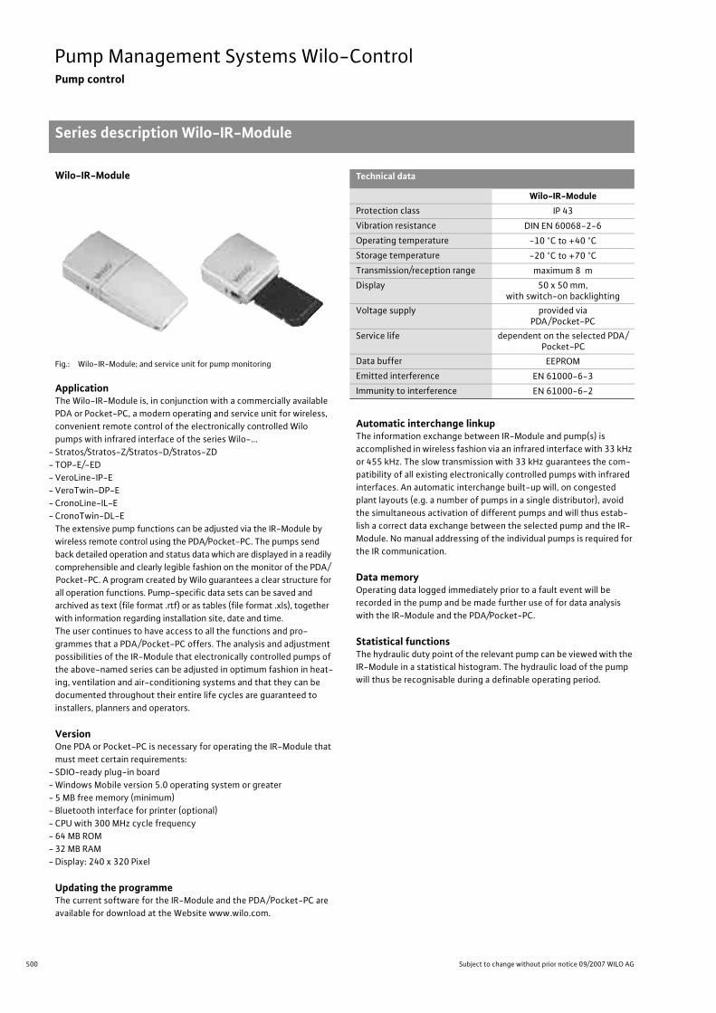
500 Subject to change without prior notice 09/2007 WILO AG
Pump Management Systems Wilo-ControlPump control
Series description Wilo-IR-Module
Wilo-IR-Module
Fig.: Wilo-IR-Module; and service unit for pump monitoring
ApplicationThe Wilo-IR-Module is, in conjunction with a commercially available PDA or Pocket-PC, a modern operating and service unit for wireless, convenient remote control of the electronically controlled Wilo pumps with infrared interface of the series Wilo-...
- Stratos/Stratos-Z/Stratos-D/Stratos-ZD- TOP-E/-ED- VeroLine-IP-E- VeroTwin-DP-E- CronoLine-IL-E- CronoTwin-DL-E
The extensive pump functions can be adjusted via the IR-Module by wireless remote control using the PDA/Pocket-PC. The pumps send back detailed operation and status data which are displayed in a readily comprehensible and clearly legible fashion on the monitor of the PDA/Pocket-PC. A program created by Wilo guarantees a clear structure for all operation functions. Pump-specific data sets can be saved and archived as text (file format .rtf) or as tables (file format .xls), together with information regarding installation site, date and time.The user continues to have access to all the functions and pro-grammes that a PDA/Pocket-PC offers. The analysis and adjustment possibilities of the IR-Module that electronically controlled pumps of the above-named series can be adjusted in optimum fashion in heat-ing, ventilation and air-conditioning systems and that they can be documented throughout their entire life cycles are guaranteed to installers, planners and operators.
VersionOne PDA or Pocket-PC is necessary for operating the IR-Module that must meet certain requirements:
- SDIO-ready plug-in board- Windows Mobile version 5.0 operating system or greater- 5 MB free memory (minimum)- Bluetooth interface for printer (optional)- CPU with 300 MHz cycle frequency- 64 MB ROM- 32 MB RAM- Display: 240 x 320 Pixel
Updating the programmeThe current software for the IR-Module and the PDA/Pocket-PC are available for download at the Website www.wilo.com.
Automatic interchange linkupThe information exchange between IR-Module and pump(s) is accomplished in wireless fashion via an infrared interface with 33 kHz or 455 kHz. The slow transmission with 33 kHz guarantees the com-patibility of all existing electronically controlled pumps with infrared interfaces. An automatic interchange built-up will, on congested plant layouts (e.g. a number of pumps in a single distributor), avoid the simultaneous activation of different pumps and will thus estab-lish a correct data exchange between the selected pump and the IR-Module. No manual addressing of the individual pumps is required for the IR communication.
Data memoryOperating data logged immediately prior to a fault event will be recorded in the pump and be made further use of for data analysis with the IR-Module and the PDA/Pocket-PC.
Statistical functionsThe hydraulic duty point of the relevant pump can be viewed with the IR-Module in a statistical histogram. The hydraulic load of the pump will thus be recognisable during a definable operating period.
Technical data
Wilo-IR-ModuleProtection class IP 43Vibration resistance DIN EN 60068-2-6Operating temperature -10 °C to +40 °CStorage temperature -20 °C to +70 °CTransmission/reception range maximum 8 mDisplay 50 x 50 mm,
with switch-on backlightingVoltage supply provided via
PDA/Pocket-PCService life dependent on the selected PDA/
Pocket-PCData buffer EEPROMEmitted interference EN 61000-6-3Immunity to interference EN 61000-6-2

501
Pump Management Systems Wilo-ControlPump control
Series description Wilo-IR-Module
Wilo Catalogue A1 - 50 Hz - Circulating Pumps in Glandless Design
Hea
ting,
Air-
cond
ition
ing,
Co
olin
gSe
cond
ary
Hot W
ater
Circ
ulat
ion
Sola
r The
rmal
, Geo
ther
mal
En
ergy
Sys
tem
sSe
rvic
e/Ac
cess
orie
s, S
yste
ms
Switc
hgea
rs a
nd C
ontr
ol D
evic
esPu
mp
Man
agem
ent S
yste
ms
Main menu The main menu of the IR-Module enables access to nine function menus.
Function menu 1: “Communication”This function menu initiates the automatic linkup between the IR-Module and the pump. All of the recognised pumps in a single group (e.g. distributor) can be selectively activated here.
Function menu 2: “Display/operating data”Hydraulic and electrical operating data are displayed in this function menu. Status messages and infor-mation concerning pumping modes can continue to be called up.
Function menu 3: “Operation”Operating data and status information are displayed in this function menu. Settings such as the selection of the control mode and setpoint changes can be undertaken at the same time.

502 Subject to change without prior notice 09/2007 WILO AG
Pump Management Systems Wilo-ControlPump control
Series description Wilo-IR-Module
Function menu 4: “Statistics”Statistical data are displayed in this function menu which can also be reset here. A histogram shows the percentile distribution of the volume flow through-out the operating time. This makes the hydraulic load of the pump transparent.
Function menu 5: “Service”This function menu makes possible a detailed fault diagnosis with the stored operating data that were present prior to the last error that occurred. The fault storage (FIFO principle) of the pump is extracted and various self-tests can be carried out at the pump.
Function menu 6: “Adapt”This function menu enables the selection of a country-specific language. In addition, SI units or US units can be selected for the presentation of the operating data.
Function menu 7: “Printing”Detests for pumps can be printed out in this func-tion menu. The data transfer to a mobile printer is carried out by means of a Bluetooth interface. The printer must be set up separately.
Function menu 8: “Opening”Saved data sets for pumps are opened in this func-tion menu.

503
Pump Management Systems Wilo-ControlPump control
Series description Wilo-IR-Module
Wilo Catalogue A1 - 50 Hz - Circulating Pumps in Glandless Design
Hea
ting,
Air-
cond
ition
ing,
Co
olin
gSe
cond
ary
Hot W
ater
Circ
ulat
ion
Sola
r The
rmal
, Geo
ther
mal
En
ergy
Sys
tem
sSe
rvic
e/Ac
cess
orie
s, S
yste
ms
Switc
hgea
rs a
nd C
ontr
ol D
evic
esPu
mp
Man
agem
ent S
yste
ms
Function menu 9: “Saving”Detests for pumps are stored in this function menu together with details concerning installation-spe-cific designations. Date and time are automatically included in file names, so that multiple saving of a single data set will result in a chronological sequence.
Wilo-Dia-Log
Fig.: Wilo-Dia-Log
The complete package for the servicing, maintenance and documentation of elec-tronically controlled Wilo pumps with infrared interface, consisting of:
- IR-Module complete- Pocket-PC, preconfigured with the Microsoft Windows Mobile Version 5.0 operat-
ing system and “IR-Module” user software- Power supply unit for Pocket-PC- Data transfer cable from the Pocket-PC to a computer (USB interface)- Portable printer- Power supply unit for printer- Paper roll for printer- Documentation and software

504 Subject to change without prior notice 09/2007 WILO AG
Pump Management Systems Wilo-ControlPump control
Series description Wilo-IR-Monitor
Wilo-IR-Monitor
Fig.: Wilo-IR-Monitor and service unit for pump monitoring
ApplicationModern operating and service unit for convenient remote control of the electronically controlled Wilo pumps with infrared interface of the series Wilo-...
- Stratos/Stratos-Z/Stratos-D/Stratos-ZD- TOP-E/-ED- VeroLine-IP-E- VeroTwin-DP-E- CronoLine-IL-E- CronoTwin-DL-E
The IR-Monitor can be used in conjunction with all conventional glandless and glanded pumps without IR interfaces. It is capable of checking the direction of rotation, the rotating-field frequency and the current operating status of each pump and standard motor with the IR-Monitor.The numerous pump functions can be remotely monitored by wire-less control. All operating steps and status reports are clearly graphi-cally displayed.The functionality of the IR monitor is closely linked with the proper-ties of the high-efficiency and/or energy-saving pumps. Operation of the IR-Monitor corresponds to that of the pump itself, i.e. modifica-tion and confirmation of the values that have been newly adjusted is carried out by rotating and pressing the red operating button (one-button operation).The functional capacity has mainly been tailored for the use by con-tractors and service personnel.
VersionShock resistant due to its sturdy and robust plastic casing and the scratch-resistant monitor screen. A carrying case for additional pro-tection is also included in the scope of delivery.
Automatic interchange linkupThe information exchange between the IR-Monitor and the pump is wireless by infrared light. An automatic interchange built-up will, on congested plant layouts (e.g. a number of pumps installed closely side-by-side), avoid the simultaneous activation of different pumps and will thus establish a correct data exchange between the selected pump and the IR-Monitor. Manual coding of the individual pumps is not required.
Data memoryOperating data logged immediately prior to a fault event will be recorded in the pump and be made further use of for data analysis with the IR-Monitor.
Statistical functionsThe hydraulic performance (volume flow) of the relevant pump can be viewed with the IR-Monitor in a statistical histogram.The load profile of the hydraulic plant will thus become perceptible over the range of a defined operating period.A non-fading data storage medium (EEPROM) is available for buffer-ing preset values.
Battery monitoringBattery condition is subject to constant check. A warning light will be displayed to indicate fading capacity
Technical data
Wilo-IR-MonitorProtection class IP 43Vibration resistance DIN EN 60068-2-6Operating temperature -10 °C to +40 °CStorage temperature -20 °C to +70 °CTransmission/reception range maximum 8 mDisplay 50 x 50 mm,
with switch-on backlightingVoltage supply 2 pc. Mignon alkali battery cells
1.5 V size AA (included in the scope of delivery)
Service life approximately 24 hrs. when on and illuminated
Data buffer EE-PromEmitted interference EN 61000-6-3Immunity to interference EN 61000-6-2

505
Pump Management Systems Wilo-ControlPump control
Series description Wilo-IR-Monitor
Wilo Catalogue A1 - 50 Hz - Circulating Pumps in Glandless Design
Hea
ting,
Air-
cond
ition
ing,
Co
olin
gSe
cond
ary
Hot W
ater
Circ
ulat
ion
Sola
r The
rmal
, Geo
ther
mal
En
ergy
Sys
tem
sSe
rvic
e/Ac
cess
orie
s, S
yste
ms
Switc
hgea
rs a
nd C
ontr
ol D
evic
esPu
mp
Man
agem
ent S
yste
ms
Main menuThe main menu of the IR-Monitor is divided into 6 function menus:
Menu 1: “Communication”This menu initiates the automatic linkup between the IR-Monitor and the pump.Selective activation of individual pumps within a set of pumps � 1000 �� is also possible here.
Menu 2: “Display”Here it is possible to read system data, e.g. actual electrical and hydraulic values, operating status, operating mode, fault reports.For correct interpretation, the display always distin-guishes clearly between “Single-head” and “Twin-head pump”.
Menu 3: “Operate”In this menu, data can be both displayed (current setpoint value) and changed, e.g. control mode, setpoint value, pump ON/OFF, disabling the manual operating level at the pump (pump ON/OFF, Ext. Off and SSM remaining active).
Menu 4: “Statistics”So that operating periods can be analysed, this menu offers clearly definable histograms of hydrau-lic performance (volume flow Q), thus giving an appreciation of the system load conditions over a definable operating period. It also records hours-run and operating data.
Menu 5: “Service”In the service menu the user is given the open of fault diagnosis, fault statistics, function-testing the pump, the IR-Monitor and the serial digital inter-face, as well as direction-of-rotation check and frequency measurement of the rotating field.The latter two checks can also be conducted with all conventional pumps without IR interface.
Menu 6: “Adapt”Language selection, contrast and time-out set-tings, changing and activating the personal pass-word are available to adapt the IR-Monitor to suit individual requirements.
Series descrip-tion Wilo-IR-Monitor

506 Subject to change without prior notice 09/2007 WILO AG
Pump Management Systems Wilo-ControlPump control
Technical data Wilo-IF-Modules Stratos/ Wilo-IF-Modules PLR, LON, CAN
Stra
tos
IF-M
odul
e PL
RIF
-Mod
ule
PLR
Stra
tos
IF-M
odul
e LO
NIF
-Mod
ule
LON
Stra
tos
IF-M
odul
e CA
NIF
-Mod
ule
CAN
Terminal cross-section 2.5 mm2 2.5 mm2 1.5 mm2
Maximum cable length
200 m
– 1000 m for bus topology with maximum 3 m long spur lines
– 500 m with free topology, with a maximum of 400 m between two nodes that commu-nicate with one another
– maximum bus length: 200 m– maximum length of a spur line: 10 m– maximum cumulative length of all
spur lines: 50 m
Bus cableCable shielded
minimum 2 x 0.34 mm2, drilled (10 t/m),shielded cable,(e.g. J-Y(st)Y 2 x 2 x 0.8 mm2)
e.g. CAN bus cable 1 x 2 x 0.34minimum 2 x 0.34 mm2, shielded cable, characteristic impedance 120 �
Transceiver – FTT 10 A –
Voltage supply – 5 V=/15 V= via the pump 5 V=/15 V= via the pump
Current consumption – 30 mA 30 mA
Neuron ID/address – 2-part sticker with barcode of Neu-ron ID
2-part sticker with open field for address
Protocol – LONTalk as per CANopen
Contact load – – –
Dielectric strength – – –
Control input 0 - 10 V
Terminal cross-section – – –
Maximum cable length – – –
Dielectric strength – – –
Input resistance of voltage input – – –
Accuracy – – –

507
Pump Management Systems Wilo-ControlPump control
Technical data Wilo-IF-Modules Stratos Ext.Aus, Ext.Min, SBM, Ext.Aus/SBM
Wilo Catalogue A1 - 50 Hz - Circulating Pumps in Glandless Design
Hea
ting,
Air-
cond
ition
ing,
Co
olin
gSe
cond
ary
Hot W
ater
Circ
ulat
ion
Sola
r The
rmal
, Geo
ther
mal
En
ergy
Sys
tem
sSe
rvic
e/Ac
cess
orie
s, S
yste
ms
Switc
hgea
rs a
nd C
ontr
ol D
evic
esPu
mp
Man
agem
ent S
yste
ms
Stra
tos
IF-M
odul
e Ex
t. O
ff
Stra
tos
IF-M
odul
e Ex
t. M
in
Stra
tos
IF-M
odul
e SB
M
Stra
tos
IF-M
odul
eEx
t. O
ff/S
BM
Function:Ext. Off
Function:SBM
Terminal cross-section 1.5 mm2 1.5 mm2 1.5 mm2 1.5 mm2 1.5 mm2
Maximum cable length 100 m 100 m 100 m 100 m 100 m
Bus cable Cable shielded Cable shielded – Cable shielded –
Transceiver – – – – –
Voltage supply – – – – –
Current consumption – – – – –
Neuron ID – – – – –
Protocol – – – – –
Contact load 24 VDC, 10 mA
24 VDC, 10 mA
24 VAC, .0.2 A
24 VDC.10 mA /
24 VAC, .0.2 A
Dielectric strength 250 V AC 250 V AC – 250 V AC –
Control input 0 - 10 V
Terminal cross-section 1.5 mm2 1.5 mm2 1.5 mm2 – –
Maximum cable length 25 m (shielded cable)
25 m (shielded cable)
25 m (shielded cable) – –
Dielectric strength 24 V = 24 V = 24 V = – –
Input resistance of voltage input >100 k� >100 k� >100 k� – –
Accuracy ± 5 % ± 5 % ± 5 % – –

508 Subject to change without prior notice 09/2007 WILO AG
Pump Management Systems Wilo-ControlPump control
Function overview Wilo-Stratos pumps Wilo-IF-Modules Stratos
1) programmable via IR-Module, IR-Monitor, LON or CAN
Wilo-Stratos/Stratos-Z with Stratos IF-Module Wilo-Stratos-D/Stratos-ZD with 2 x Stratos IF-Module
• Integrated electronic performance control for operation at constant/variable differential pressure
- simplifies pump configuration- duty point-adjustable- reduces noise and saves electricity• Integrated full motor protection• Thermal insulation as standard• Retrofittable Stratos IF-Modules for function expansion
• Integrated electronic performance control for operation at constant/variable differential pressure
- simplifies pump configuration- duty point-adjustable- reduces noise and saves electricity• Integrated full motor protection• Twin-head pump switchover valve• Retrofittable Stratos IF-Modules for function expansion
Function table Wilo-Stratos/Stratos-Z/Stratos-D/Stratos-ZD
Function Single-head pumps Wilo-Stratos
Single-head pumps Wilo-Stratos-Z
Twin-head pumps Wilo-Stratos-D
Twin-head pumps Wilo-Stratos-ZD
Electrical connection
1~230 V, 50/60 Hz • • • •
Manual functions
Pump ON/OFF • • • •Setting control mode(�p-c, �p-v, �p-T1), manual control mode) • • • •
Setting setpoint differential-pressure value • • • •Setting speed (manual setting) • • • •
Automatic functions
Stageless performance control �p-c • • • •Stageless performance control �p-v • • • •Stageless performance control �p-T • • • •Automatic setback in low-load periods (e.g. at night) • • • •Full motor protection with fault trip • • • •
• = available, – = not available
Function overview Wilo-Stratos pumps Wilo-IF-Modules Stratos

509
Pump Management Systems Wilo-ControlPump control
Function overview Wilo-Stratos pumps Wilo-IF-Modules Stratos
Wilo Catalogue A1 - 50 Hz - Circulating Pumps in Glandless Design
Hea
ting,
Air-
cond
ition
ing,
Co
olin
gSe
cond
ary
Hot W
ater
Circ
ulat
ion
Sola
r The
rmal
, Geo
ther
mal
En
ergy
Sys
tem
sSe
rvic
e/Ac
cess
orie
s, S
yste
ms
Switc
hgea
rs a
nd C
ontr
ol D
evic
esPu
mp
Man
agem
ent S
yste
ms
Function table Wilo-Stratos/Stratos-Z/Stratos-D/Stratos-ZD (continued)
Function Single-head pumps Wilo-Stratos
Single-head pumps Wilo-Stratos-Z
Twin-head pumps Wilo-Stratos-D
Twin-head pumps Wilo-Stratos-ZD
External control functions
Control input Overriding Off • 1) 6) • 1) 6) • 1) 6) • 1) 6)
Control input Overriding Min • 2) • 2) • 2) • 2)
Control input 0 - 10 V (remote speed adjustment) • 1) 2) 3) • 1) 2) 3) • 1) 2) 3) • 1) 2) 3)
Control input 0 - 10 V(remote setpoint adjustment) • 1) 2) 3) • 1) 2) 3) • 1) 2) 3) • 1) 2) 3)
Signalling and display functions
Collective fault signal (potential-free NC contact), for function details see Wilo-Control • • • •
Run signal (potential-free NO contact) For function, see Wilo-Control • 3) 6) • 3) 6) • 3) 6) • 3) 6)
Fault signal light • • • •IR communication run signal light • • • •Fault code • • • •LC display for indicating pump data • • • •
Data exchange
Infrared interface for wireless data exchange with the Wilo-IR-Module/ IR-Monitor operating and serv-ice unit
• 10) • 10) • 10) • 10)
Serial digital PLR interface for connection to BA building automation via Wilo interface converter or company-specific coupling module
• 4) • 4) • 4) • 4)
Serial digital LON interface for connection to a LONWorks network • 5) • 5) • 5) • 5)
Serial digital CAN interface for connection to a CAN bus system • 7) • 7) • 7) • 7)
Dual pump management(2 single-head or 1 x twin-head pump)
Main/standby operation (automatic. fault-actuated switchover/time-sensitive pump duty cycling) • 8) • 8) • 8) • 8)
Parallel operation (efficiency-optimised peak-load cut-in and out) • 8)9) • 8) 9) • 8) • 8)
• = available, – = not available
1) IF-Module Stratos Ext. Off2) IF-Module Stratos Ext. Min3) IF-Module Stratos SBM4) IF-Module Stratos PLR5) IF-Module Stratos LON6) Stratos IF-Module Ext. Off/SBM7) Stratos IF-Module CAN8) Various combinations possible with Stratos IF-Modules, see “Pump management Wilo-Control”9) Dual pump management with 2 single-head pumps possible only if the equivalent twin-head pump is also listed in the Wilo Catalogue10) For functions, see Wilo-IR-Module/IR Monitor function table

510 Subject to change without prior notice 09/2007 WILO AG
Pump Management Systems Wilo-ControlPump control
Function overview Wilo-Stratos pumps Wilo-IF-Modules Stratos
Integrable dual pump management for 1 x Wilo-Stratos-D/Stratos-ZD or 2 x Wilo-Stratos/Stratos-ZFunctions of dual pump management that can be integrated:
- Main/Standby operation- Parallel operation (efficiency-optimised peak-load cut-in and out)- Base-load pump exchange after 24 hours of accumulated operating time- Automatic fault-actuated switchover
Combination possibilities with the Stratos IF-Modules for integrated dual pump management1)
Function 2)
Stra
tos
IF-M
odul
e PL
R
Stra
tos
IF-M
odul
e LO
N
Stra
tos
IF-M
odul
e CA
N
Stra
tos
IF-M
odul
e Ex
t. O
ff
Stra
tos
IF-M
odul
e Ex
t. M
in
Stra
tos
IF-M
odul
e SB
M
Stra
tos
IF-M
odul
e Ex
t. O
ff/S
BM
Serial digital PLR interface for connection to BA building auto-mation via Wilo interface converter or onsite coupling module
1x MA1x SL – – – – – –
Serial digital LON interface for connection to LONWorks net-works, FTT 10 A transceiver 1x SL 1x MA – – – – –
Serial digital CAN interface for connection to a CAN bus system 1x SL – 1x MA – – – –Input for potential-free NC contact with the function Ext. Off 3)
Control input 0 - 10 V for remote speed adjustment or remote setpoint adjustment 4)
1 x SL – – 1x MA – – –
Input for potential-free NC contact with the function Ext. Min 5)
Control input 0 - 10 V for remote speed adjustment or remote setpoint adjustment 4)
1 x SL – – – 1 x MA – –
Run signal SBM as potential-free NO contact 6)
Control input 0 - 10 V for remote speed adjustment or remote setpoint adjustment 4)
– – – – – 1 x MA1 x SL –
Input for potential-free NC contact with the function Ext. Off 3)
and run signal SBM as potential-free NO contact 6) – – – – – – 1 x MA1 x SL
Fault signal SSM integrated in the pump as potential-free NC contact7) – – – – – –
MA = Master, SL = Slave
1) All Stratos IF-Modules can be combined with one another in any configuration desired for integrated dual pump management. The table shows the most inexpensive combinations that do not require dispensing with functional properties.
2) The control function is placed on the MA of the twin-head pump; it is effective for the entire twin-head pump.The SL of the twin-head pump receives the respective command from the MA via the DP interface of the IF-Modules (2-wire connection cable).The control functions (inputs) on the SL are not active. The PLR interface on the SL is not active. The IR interface on the SL is not active.The signal outputs (SSM, SBM) at the SL are active.
3) Both drives are at a stop.4) The control input 0 - 10 V has a variety of additional functions, see Table “Function of the analogue input 0 - 10 V in the integrated dual pump management” and
“High-efficiency pumps Planning guide”.5) The base-load pump runs at minimum speed, the other drive is at a stop.6) Run signal displays the rotation of the respective drive (individual run signals separate for MA and SL).7) The SSM on the MA can be set as individual (for the MA) or collective fault signal (for MA and SL) with the IR-Module/IR-Monitor.
Function overview Wilo-Stratos pumps Wilo-IF-Modules Stratos

511
Pump Management Systems Wilo-ControlPump control
Function overview Wilo-Stratos pumps Wilo-IF-Modules Stratos
Wilo Catalogue A1 - 50 Hz - Circulating Pumps in Glandless Design
Hea
ting,
Air-
cond
ition
ing,
Co
olin
gSe
cond
ary
Hot W
ater
Circ
ulat
ion
Sola
r The
rmal
, Geo
ther
mal
En
ergy
Sys
tem
sSe
rvic
e/Ac
cess
orie
s, S
yste
ms
Switc
hgea
rs a
nd C
ontr
ol D
evic
esPu
mp
Man
agem
ent S
yste
ms
Function of the analogue input 0 - 10 V in integrated dual pump management
Function 0 - 10 V Twin-head pump operating modeMain-/ Standby operation
/ Parallel operation
+
Remote speed adjustment (DDC)0 - 1 V: Off 1)
1 - 3 V: Min. speed 1)
3 - 10 V: nmin…nmax
- Speed of base-load pump follows voltage signal
- Base-load pump exchange after 24 operat-ing hours
- Both pumps follow voltage signal with the same speed
Remote setpoint adjustment 2)
0 - 1 V: Off 1)
1 - 3 V: Hmin3 - 10 V: Hmin…Hmax
- Base-load pump controls differential pres-sure
- Base-load pump exchange after 24 operat-ing hours
- Efficiency-optimised On/Off control of peak-load pump
- Base-load pump exchange after 24 operat-ing hours
1) Observe On/Off switching hysteresis, see “High-efficiency pumps Planning guide”2) If the functions Ext. Off and Ext. Min are also simultaneously called for via potential-free contacts,
then one Wilo-Control AnaCon and 2 x Stratos PLR IF-Modules are required. All functions are then available at the Wilo-Control AnaCon.

512 Subject to change without prior notice 09/2007 WILO AG
Pump Management Systems Wilo-ControlPump control
Wilo-IF-Modules Stratos for single-head pumps
1 x Wilo-IF-Module Stratos PLR
Plug-in module for single-head pumps of the Wilo-Stratos and Wilo-Stratos-Z series
>Additional functions• Serial digital Interface PLR for connection to BA building automation.
Connection via- Wilo interface converters or- Company-specific coupling modules• Transfer of the following data items as control commands to the
pump:- Control mode - Setpoint delivery head/speed- Pump ON/OFF- Setback operation• Transfer of the following data items as signals from the pump:- Actual value, delivery head- Actual value, volume flow- Actual value, power consumption- Actual value, power output- Actual value, motor current- Operating hours- Actual value, speed - Detailed fault reports- Status reports• Twin-head pumps interface DP for integrated dual pump manage-
ment of 2 x single-head or 1 x twin-head pump (see Wilo-IF-Module Stratos for twin-head pumps)
Terminal diagram
PLR
DP
L N PE SSM
1~230 V
Wilo-IF-module Stratos PLR
Wilo Interface converter orcompany-specific coupling module
Wilo-StratosWilo-Stratos-Z

513
Pump Management Systems Wilo-ControlPump control
Wilo-IF-Modules Stratos for single-head pumps
Wilo Catalogue A1 - 50 Hz - Circulating Pumps in Glandless Design
Hea
ting,
Air-
cond
ition
ing,
Co
olin
gSe
cond
ary
Hot W
ater
Circ
ulat
ion
Sola
r The
rmal
, Geo
ther
mal
En
ergy
Sys
tem
sSe
rvic
e/Ac
cess
orie
s, S
yste
ms
Switc
hgea
rs a
nd C
ontr
ol D
evic
esPu
mp
Man
agem
ent S
yste
ms
1 x Wilo-IF-Module Stratos LON
Plug-in module for single-head pumps of the Wilo-Stratos and Wilo-Stratos-Z series
> Additional functions• Serial digital LON interface for connection to LONWorks networks.• Transfer of the following data items as control commands to the
pump:- Operating mode- Setpoint- External sensor data
Transfer of the following data points as messages from the pump:- Hydraulic operating data- Electrical operating data- Status reports- Fault signals• Twin-head pumps interface DP for integrable dual pump manage-
ment of 2 x single-head or 1 x twin-head pump (see Wilo-IF-Module Stratos for twin-head pumps)
> Standards• LONMark Application Layer Interoperability Guidelines version 3.2• LONMark Layers 1-6 Interoperability Guidelines 3.0• LONMark Functional Profile “Pump controller Object for HVAC Appli-
cations” (8120_10.pdf)
> Delivery statusThe LON IF-Module LON is supplied as “Application unconfigured” in line with LONMark Application Layer Interoperability Guidelines.
> DocumentationWe make the following documentation available to you on our homepage www.wilo.com (- Products, - Wilo switchgears):LONMark Functional Profile “Pump controller Object for HVAC Appli-cations” (8120_10.pdf)
• Download application over network: *.NXE/*.APB• External interface files: *.XIF/*.XFB• Device resource files: *.ENU/*.FMT/*.FPT/*.TYP
Terminal diagram
LONWorks network
LON
DP
L N PE SSM1~230 V
Wilo-StratosWilo-Stratos-Z
Wilo-IF-module Stratos LON
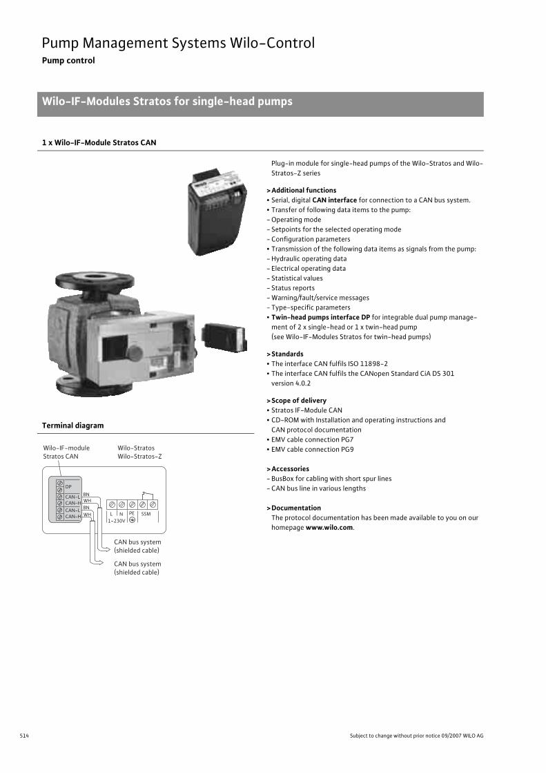
514 Subject to change without prior notice 09/2007 WILO AG
Pump Management Systems Wilo-ControlPump control
Wilo-IF-Modules Stratos for single-head pumps
1 x Wilo-IF-Module Stratos CAN
Plug-in module for single-head pumps of the Wilo-Stratos and Wilo-Stratos-Z series
>Additional functions• Serial, digital CAN interface for connection to a CAN bus system.• Transfer of following data items to the pump:- Operating mode- Setpoints for the selected operating mode- Configuration parameters• Transmission of the following data items as signals from the pump:- Hydraulic operating data- Electrical operating data- Statistical values- Status reports- Warning/fault/service messages- Type-specific parameters• Twin-head pumps interface DP for integrable dual pump manage-
ment of 2 x single-head or 1 x twin-head pump (see Wilo-IF-Modules Stratos for twin-head pumps)
>Standards• The interface CAN fulfils ISO 11898-2• The interface CAN fulfils the CANopen Standard CiA DS 301
version 4.0.2
>Scope of delivery• Stratos IF-Module CAN• CD-ROM with Installation and operating instructions and
CAN protocol documentation• EMV cable connection PG7• EMV cable connection PG9
>Accessories- BusBox for cabling with short spur lines- CAN bus line in various lengths
>DocumentationThe protocol documentation has been made available to you on our homepage www.wilo.com.
Terminal diagram
DP
CAN-LCAN-HCAN-LCAN-H WH
BNWHBN
L N PE SSM1~230V
CAN bus system(shielded cable)
CAN bus system(shielded cable)
Wilo-StratosWilo-Stratos-Z
Wilo-IF-moduleStratos CAN
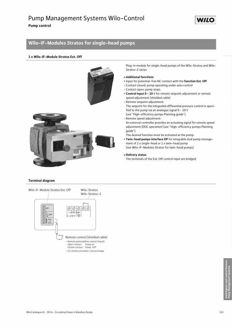
515
Pump Management Systems Wilo-ControlPump control
Wilo-IF-Modules Stratos for single-head pumps
Wilo Catalogue A1 - 50 Hz - Circulating Pumps in Glandless Design
Hea
ting,
Air-
cond
ition
ing,
Co
olin
gSe
cond
ary
Hot W
ater
Circ
ulat
ion
Sola
r The
rmal
, Geo
ther
mal
En
ergy
Sys
tem
sSe
rvic
e/Ac
cess
orie
s, S
yste
ms
Switc
hgea
rs a
nd C
ontr
ol D
evic
esPu
mp
Man
agem
ent S
yste
ms
1 x Wilo-IF-Module Stratos Ext. Off
Plug-in module for single-head pumps of the Wilo-Stratos and Wilo-Stratos-Z series
> Additional functions• Input for potential-free NC contact with the function Ext. Off- Contact closed: pump operating under auto control- Contact open: pump stops• Control input 0 - 10 V for remote setpoint adjustment or remote
speed adjustment (shielded cable)- Remote setpoint adjustment:
The setpoint for the integrated differential pressure control is speci-fied to the pump via an analogue signal 0 - 10 V (see “High-efficiency pumps Planning guide”).
- Remote speed adjustment:An external controller provides an actuating signal for remote speed adjustment (DDC operation) (see “High-efficiency pumps Planning guide”). The desired function must be activated at the pump.
• Twin-head pumps interface DP for integrable dual pump manage-ment of 2 x single-head or 1 x twin-head pump (see Wilo-IF-Modules Stratos for twin-head pumps)
> Delivery statusThe terminals of the Ext. Off control input are bridged.
Terminal diagram
Ext.off
DP
L N PE SSM1~230 V
Wilo-StratosWilo-Stratos-Z
Wilo-IF-Module Stratos Ext. Off
0...10V
Remote control (shielded cable)– Remote potentialfree contact (input): Open contact: Pump on Closed contact: Pump "Off"– For remote actuation, remove bridge
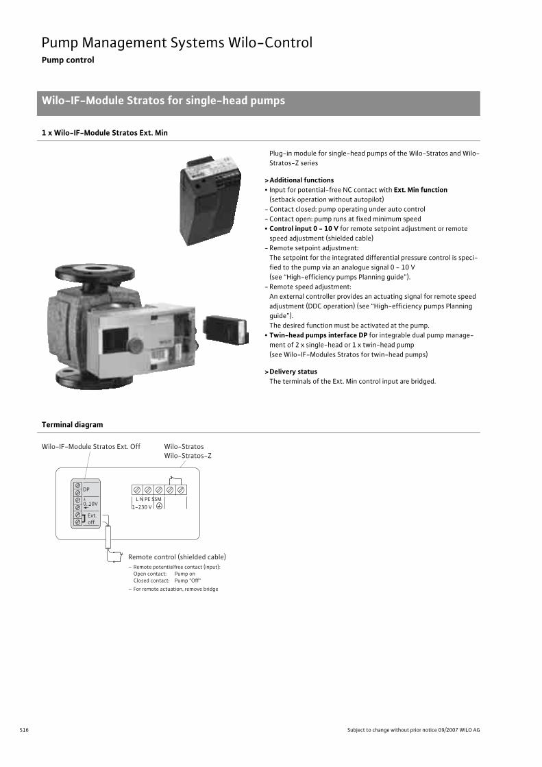
516 Subject to change without prior notice 09/2007 WILO AG
Pump Management Systems Wilo-ControlPump control
Wilo-IF-Module Stratos for single-head pumps
1 x Wilo-IF-Module Stratos Ext. Min
Plug-in module for single-head pumps of the Wilo-Stratos and Wilo-Stratos-Z series
>Additional functions• Input for potential-free NC contact with Ext. Min function
(setback operation without autopilot)- Contact closed: pump operating under auto control- Contact open: pump runs at fixed minimum speed• Control input 0 - 10 V for remote setpoint adjustment or remote
speed adjustment (shielded cable)- Remote setpoint adjustment:
The setpoint for the integrated differential pressure control is speci-fied to the pump via an analogue signal 0 - 10 V (see “High-efficiency pumps Planning guide”).
- Remote speed adjustment:An external controller provides an actuating signal for remote speed adjustment (DDC operation) (see “High-efficiency pumps Planning guide”). The desired function must be activated at the pump.
• Twin-head pumps interface DP for integrable dual pump manage-ment of 2 x single-head or 1 x twin-head pump (see Wilo-IF-Modules Stratos for twin-head pumps)
>Delivery statusThe terminals of the Ext. Min control input are bridged.
Terminal diagram
Ext.off
DP
L N PE SSM1~230 V
Wilo-StratosWilo-Stratos-Z
Wilo-IF-Module Stratos Ext. Off
0...10V
Remote control (shielded cable)– Remote potentialfree contact (input): Open contact: Pump on Closed contact: Pump "Off"– For remote actuation, remove bridge

517
Pump Management Systems Wilo-ControlPump control
Wilo-IF-Module Stratos for single-head pumps
Wilo Catalogue A1 - 50 Hz - Circulating Pumps in Glandless Design
Hea
ting,
Air-
cond
ition
ing,
Co
olin
gSe
cond
ary
Hot W
ater
Circ
ulat
ion
Sola
r The
rmal
, Geo
ther
mal
En
ergy
Sys
tem
sSe
rvic
e/Ac
cess
orie
s, S
yste
ms
Switc
hgea
rs a
nd C
ontr
ol D
evic
esPu
mp
Man
agem
ent S
yste
ms
1 x Wilo-IF-Module Stratos SBM
Plug-in module for single-head pumps of the Wilo-Stratos and Wilo-Stratos-Z series
> Additional functions• Collective run signal SBM as potential-free NO contact- Contact closed: pump operates in the specified operating mode- Contact open: pump stops• Control input 0 - 10 V for remote setpoint adjustment or remote
speed adjustment (shielded cable)- Remote setpoint adjustment:
The setpoint for the integrated differential pressure control is speci-fied to the pump via an analogue signal 0 - 10 V (see “High-efficiency pumps Planning guide”).
- Remote speed adjustment:An external controller provides an actuating signal for remote speed adjustment (DDC operation) (see “High-efficiency pumps Planning guide”). The desired function must be activated at the pump.
• Twin-head pumps interface DP for integrable dual pump manage-ment of 2 x single-head or 1 x twin-head pump (see Wilo-IF-Module Stratos for twin-head pumps)
Terminal diagram
SBM*
DP
L N PE SSM1~230 V
Wilo-IF module Stratos SBM
0...10V
* SBM: Collective run signal, normally open contact according to VDI 3814 (load capacity of the potential-free NO contact: 0.2 A, 24 V~), see Wilo Control for function
External monitoring unit
Wilo-StratosWilo-Stratos-Z

518 Subject to change without prior notice 09/2007 WILO AG
Pump Management Systems Wilo-ControlPump control
Wilo-IF-Module Stratos for single-head pumps
1 x Wilo-IF-Module Stratos Ext. Off/SBM
Plug-in module for single-head pumps of the Wilo-Stratos and Wilo-Stratos-Z series
>Additional functions• Input for potential-free NC contact with the function Ext. Off- Contact closed: pump operating under auto control- Contact open: pump stops• Collective run signal SBM as potential-free NO contact- Contact closed: pump operates in the specified operating mode- Contact open: pump stops• Twin-head pumps interface DP for integrable dual pump manage-
ment of 2 x single-head or 1 x twin-head pump (see Wilo-IF-Modules Stratos for twin-head pumps)
Terminal diagram
DP
SBM*
Ext. Off
L N PE SSM1~230 V
Remote control (shielded cable)* Remote potentialfree contact Open contact: Pump on Closed contact: Pump "Off"* For remote actuation, remove bridge
* SBM: Collective run signal, normally open contact according to VDI 3814 (load capacity of the potential-free NO contact: 0.2 A, 24 V~), see Wilo Control for function
Wilo-Stratos/-ZWilo-IF-ModuleStratos Ext. Off / SBM
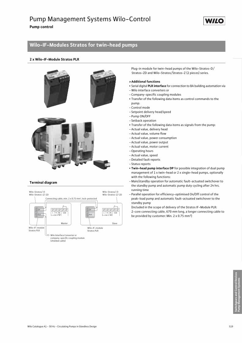
519
Pump Management Systems Wilo-ControlPump control
Wilo-IF-Modules Stratos for twin-head pumps
Wilo Catalogue A1 - 50 Hz - Circulating Pumps in Glandless Design
Hea
ting,
Air-
cond
ition
ing,
Co
olin
gSe
cond
ary
Hot W
ater
Circ
ulat
ion
Sola
r The
rmal
, Geo
ther
mal
En
ergy
Sys
tem
sSe
rvic
e/Ac
cess
orie
s, S
yste
ms
Switc
hgea
rs a
nd C
ontr
ol D
evic
esPu
mp
Man
agem
ent S
yste
ms
2 x Wilo-IF-Module Stratos PLR
Plug-in module for twin-head pumps of the Wilo-Stratos-D/Stratos-ZD and Wilo-Stratos/Stratos-Z (2 pieces) series.
> Additional functions• Serial digital PLR interface for connection to BA building automation via- Wilo interface converters or- Company-specific coupling modules• Transfer of the following data items as control commands to the
pump:- Control mode - Setpoint delivery head/speed- Pump ON/OFF- Setback operation• Transfer of the following data items as signals from the pump:- Actual value, delivery head- Actual value, volume flow- Actual value, power consumption- Actual value, power output- Actual value, motor current- Operating hours- Actual value, speed - Detailed fault reports- Status reports• Twin-head pump interface DP for possible integration of dual pump
management of 1 x twin-head or 2 x single-head pumps, optionally with the following functions:
- Main/standby operation for automatic fault-actuated switchover to the standby pump and automatic pump duty cycling after 24 hrs. running time
- Parallel operation for efficiency-optimised On/Off control of the peak-load pump and automatic fault-actuated switchover to the standby pump(Included in the scope of delivery of the Stratos IF-Module PLR: 2-core connecting cable, 670 mm long, a longer connecting cable to be provided by customer: Min. 2 x 0.75 mm2)
Terminal diagram
PLR
DP
L N PE 1~230 V PLR
DP
Master
L N PE 1~230 V
Slave
SSMSSM
Wilo-Stratos/-DWilo-Stratos-Z/-ZD
Wilo-Stratos/-DWilo-Stratos-Z/-ZD
Wilo Interface Converter orcompany-speci�c coupling module(shielded cable)
Wilo-IF-module Stratos PLR
Wilo-IF-moduleStratos PLR
Connecting cable, min. 2 x 0.75 mm2, lock-protected

520 Subject to change without prior notice 09/2007 WILO AG
Pump Management Systems Wilo-ControlPump control
Wilo-IF-Module Stratos for twin-head pumps
Wilo-IF-Module Stratos 1 x LON and 1 x PLR
Plug-in module for twin-head pumps of the Wilo-Stratos-D/Stratos-ZD and Wilo-Stratos/Stratos-Z (2 pieces) series.For dual pump management a PLR module is required in addition to the LON function module.The functions of the “LON” module are applicable to the entire twin-head pump.
>Additional functions• Serial digital LON interface for connection to LONWorks networks. In
the LONWorks network, data items are transmitted for the twin-head pump as a complete single unit; there is no differentiation between Master and Slave.Transfer of the following data items as control commands to the pump:
- Operating mode- Setpoint- Data from external sensors• Transfer of the following data items as signals from the pump:- Hydraulic operating data- Electrical operating data- Status reports- Fault signals• Twin-head pump interface DP for possible integration of dual pump
management of 1 x twin-head or 2 x single-head pumps, optionally with the following functions:
- Main/standby operation for automatic fault-actuated switchover to the standby pump and automatic pump duty cycling after 24 hrs. running time
- Parallel operation for efficiency-optimised On/Off control of the peak-load pump and automatic fault-actuated switchover to the standby pump (Included in the scope of delivery of the Stratos IF-Module PLR: 2-core connecting cable, 670 mm long, a longer connecting cable to be provided by customer: Min. 2 x 0.75 mm2)
>Standards• LONMark Application Layer Interoperability Guidelines version 3.2• LONMark Layers 1-6 Interoperability Guidelines 3.0• LONMark Functional Profile “Pump controller Object for HVAC Appli-
cations” (8120_10.pdf)
>Delivery statusThe LON IF-Module LON is supplied as “Application unconfigured” in line with LONMark Application Layer Interoperability Guidelines.
>DocumentationWe make the following documentation available to you on our homepage www.wilo.com (- Products, - Wilo switchgears):LONMark Functional Profile “Pump controller Object for HVAC Appli-cations” (8120_10.pdf)
• Download application over network: *.NXE/*.APB• External interface files: *.XIF/*.XFB• Device resource files: *.ENU/*.FMT/*.FPT/
*.TYP
Terminal diagram
LON
DP
L N PE 1~230 V PLR
DP
Master
L N PE 1~230 V
Slave
SSMSSM
Wilo-Stratos/-DWilo-Stratos-Z/-ZD
Wilo-Stratos/-DWilo-Stratos-Z/-ZD
LONWorks network(shielded cable)
Wilo-IF-module Stratos LON
Wilo-IF-moduleStratos PLR
Connecting cable, min. 2 x 0.75 mm2, lock-protected
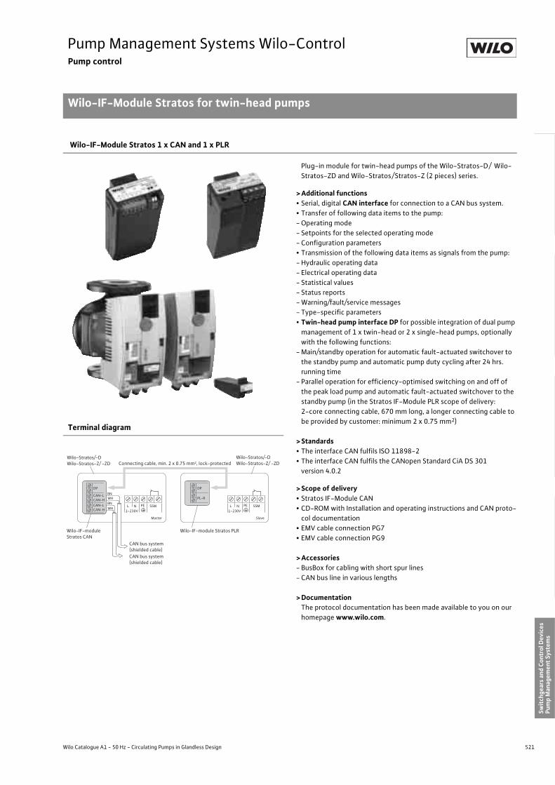
521
Pump Management Systems Wilo-ControlPump control
Wilo-IF-Module Stratos for twin-head pumps
Wilo Catalogue A1 - 50 Hz - Circulating Pumps in Glandless Design
Hea
ting,
Air-
cond
ition
ing,
Co
olin
gSe
cond
ary
Hot W
ater
Circ
ulat
ion
Sola
r The
rmal
, Geo
ther
mal
En
ergy
Sys
tem
sSe
rvic
e/Ac
cess
orie
s, S
yste
ms
Switc
hgea
rs a
nd C
ontr
ol D
evic
esPu
mp
Man
agem
ent S
yste
ms
Wilo-IF-Module Stratos 1 x CAN and 1 x PLR
Plug-in module for twin-head pumps of the Wilo-Stratos-D/ Wilo-Stratos-ZD and Wilo-Stratos/Stratos-Z (2 pieces) series.
> Additional functions• Serial, digital CAN interface for connection to a CAN bus system.• Transfer of following data items to the pump:- Operating mode- Setpoints for the selected operating mode- Configuration parameters• Transmission of the following data items as signals from the pump:- Hydraulic operating data- Electrical operating data- Statistical values- Status reports- Warning/fault/service messages- Type-specific parameters• Twin-head pump interface DP for possible integration of dual pump
management of 1 x twin-head or 2 x single-head pumps, optionally with the following functions:
- Main/standby operation for automatic fault-actuated switchover to the standby pump and automatic pump duty cycling after 24 hrs. running time
- Parallel operation for efficiency-optimised switching on and off of the peak load pump and automatic fault-actuated switchover to the standby pump (in the Stratos IF-Module PLR scope of delivery: 2-core connecting cable, 670 mm long, a longer connecting cable to be provided by customer: minimum 2 x 0.75 mm2)
> Standards• The interface CAN fulfils ISO 11898-2• The interface CAN fulfils the CANopen Standard CiA DS 301
version 4.0.2
> Scope of delivery• Stratos IF-Module CAN• CD-ROM with Installation and operating instructions and CAN proto-
col documentation• EMV cable connection PG7• EMV cable connection PG9
> Accessories- BusBox for cabling with short spur lines- CAN bus line in various lengths
> DocumentationThe protocol documentation has been made available to you on our homepage www.wilo.com.
Terminal diagram
DP
CAN-LCAN-HCAN-LCAN-H WH
BNWHBN
L N PE SSM
Master Slave
1~230V
Wilo-Stratos/-DWilo-Stratos-Z/ -ZD
Wilo-Stratos/-DWilo-Stratos-Z/ -ZD
Wilo-IF-moduleStratos CAN
DP
PL-R
L N PE SSM1~230V
CAN bus system(shielded cable)CAN bus system(shielded cable)
Wilo-IF-module Stratos PLR
Connecting cable, min. 2 x 0.75 mm2, lock-protected

522 Subject to change without prior notice 09/2007 WILO AG
Pump Management Systems Wilo-ControlPump control
Wilo-IF-Module Stratos for twin-head pumps
Wilo-IF-Module Stratos 1 x Ext. Off and 1 x PLR
Plug-in module for twin-head pumps of the Wilo-Stratos-D/Stratos-ZD and Wilo-Stratos/Stratos-Z (2 pieces) series.For dual pump management a PLR module is required in addition to the “Ext. Off” function module.The functions of the “Ext. Off” module are applicable to the entire dual pump.
>Additional functions• Input for potential-free NC contact with the Ext. Off Function- Contact closed: pump operating under auto control- Contact open: pump stops• Control input 0 - 10 V for remote setpoint adjustment or remote
speed adjustment (shielded cable)- Remote setpoint adjustment:
The setpoint for the integrated differential pressure control is speci-fied to the pump via an analogue signal 0 - 10 V (see “High-efficiency pumps Planning guide”).
- Remote speed adjustment:An external controller issues an actuating signal for remote speed adjustment (DDC operation). This actuating signal acts in:
- The active pump in each case in main/standby operation- Parallel operation on both pumps simultaneously (synchronised)
(see also “High-efficiency pumps Planning guide”).The desired function must be activated at the pump.
• Twin-head pump interface DP for possible integration of dual pump management of 1x twin-head or 2x single-head pumps, optionally with the following functions:
- Main/standby operation for automatic fault-actuated switchover to the standby pump and automatic pump duty cycling after 24 hrs. running time
- Parallel operation for efficiency-optimised switching on and off of the peak load pump and automatic fault-actuated switchover to the standby pump (in the Stratos IF-Module PLR scope of delivery: 2-core connecting cable, 670 mm long, a longer connecting cable to be provided by customer: Min. 2 x 0.75 mm2)
>Delivery statusThe terminals of the Ext. Off control input are bridged.
Terminal diagram
DP
L N PE1~230 V
Master
PLR
DP
L N PE 1~230 V
Slave
SSM SSM
Wilo-Stratos/-DWilo-Stratos-Z/-ZD
Wilo-Stratos/-DWilo-Stratos-Z/-ZD
Wilo-IF-ModuleStratos PLR
Remote contact (shielded cable)– Ext. potential-free contact (Input): Closed contacts: Twin-head pump on Open contacts: Twin-head pump "off"– For remote actuation, remove bridge
Wilo-IF-Module Stratos Ext. Off
Connecting cable, min. 2 x 0.75 mm 2, lock-protected
Ext.off
0...10V
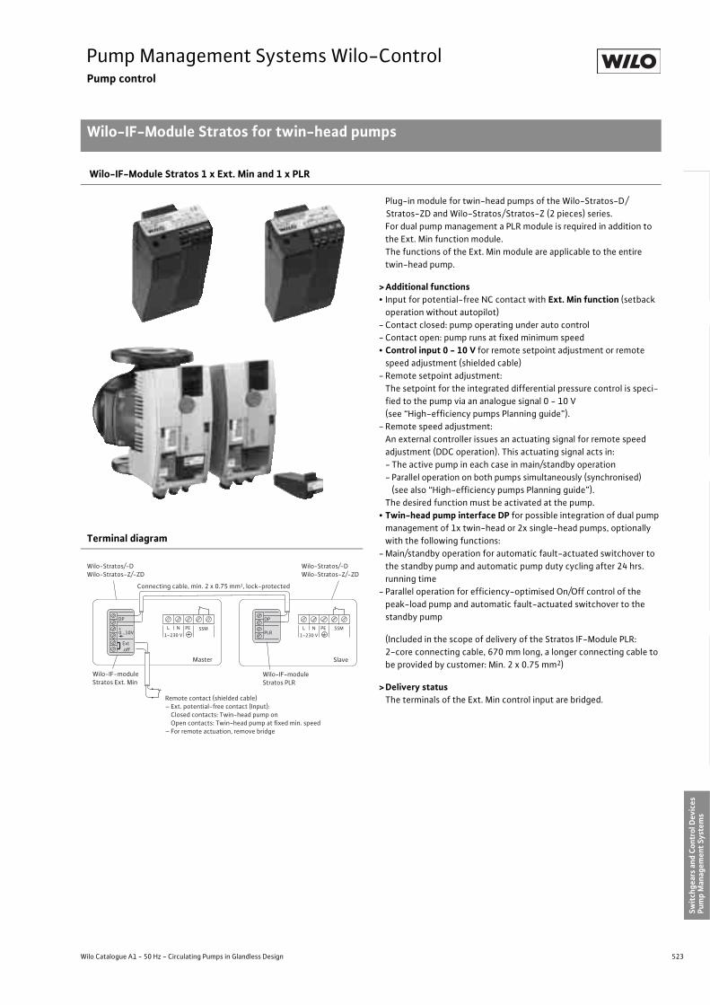
523
Pump Management Systems Wilo-ControlPump control
Wilo-IF-Module Stratos for twin-head pumps
Wilo Catalogue A1 - 50 Hz - Circulating Pumps in Glandless Design
Hea
ting,
Air-
cond
ition
ing,
Co
olin
gSe
cond
ary
Hot W
ater
Circ
ulat
ion
Sola
r The
rmal
, Geo
ther
mal
En
ergy
Sys
tem
sSe
rvic
e/Ac
cess
orie
s, S
yste
ms
Switc
hgea
rs a
nd C
ontr
ol D
evic
esPu
mp
Man
agem
ent S
yste
ms
Wilo-IF-Module Stratos 1 x Ext. Min and 1 x PLR
Plug-in module for twin-head pumps of the Wilo-Stratos-D/Stratos-ZD and Wilo-Stratos/Stratos-Z (2 pieces) series.For dual pump management a PLR module is required in addition to the Ext. Min function module.The functions of the Ext. Min module are applicable to the entire twin-head pump.
> Additional functions• Input for potential-free NC contact with Ext. Min function (setback
operation without autopilot)- Contact closed: pump operating under auto control- Contact open: pump runs at fixed minimum speed• Control input 0 - 10 V for remote setpoint adjustment or remote
speed adjustment (shielded cable)- Remote setpoint adjustment:
The setpoint for the integrated differential pressure control is speci-fied to the pump via an analogue signal 0 - 10 V (see “High-efficiency pumps Planning guide”).
- Remote speed adjustment:An external controller issues an actuating signal for remote speed adjustment (DDC operation). This actuating signal acts in:- The active pump in each case in main/standby operation- Parallel operation on both pumps simultaneously (synchronised)
(see also “High-efficiency pumps Planning guide”).The desired function must be activated at the pump.
• Twin-head pump interface DP for possible integration of dual pump management of 1x twin-head or 2x single-head pumps, optionally with the following functions:
- Main/standby operation for automatic fault-actuated switchover to the standby pump and automatic pump duty cycling after 24 hrs. running time
- Parallel operation for efficiency-optimised On/Off control of the peak-load pump and automatic fault-actuated switchover to the standby pump
(Included in the scope of delivery of the Stratos IF-Module PLR: 2-core connecting cable, 670 mm long, a longer connecting cable to be provided by customer: Min. 2 x 0.75 mm2)
> Delivery statusThe terminals of the Ext. Min control input are bridged.
Terminal diagram
DP
L N PE1~230 V
Master
PLR
DP
L N PE 1~230 V
Slave
SSM SSM
Wilo-Stratos/-DWilo-Stratos-Z/-ZD
Wilo-Stratos/-DWilo-Stratos-Z/-ZD
Wilo-IF-moduleStratos PLR
Remote contact (shielded cable)– Ext. potential-free contact (Input): Closed contacts: Twin-head pump on Open contacts: Twin-head pump at �xed min. speed– For remote actuation, remove bridge
Wilo-IF-module Stratos Ext. Min
Connecting cable, min. 2 x 0.75 mm2, lock-protected
Ext.off
0...10V

524 Subject to change without prior notice 09/2007 WILO AG
Pump Management Systems Wilo-ControlPump control
Wilo-IF-Module Stratos for twin-head pumps
2 x Wilo-IF-Module Stratos SBM
Plug-in module for twin-head pumps of the Wilo-Stratos-D/Stratos-ZD and Wilo-Stratos/Stratos-Z (2 pieces) series.For dual pump management an extra SBM function module is required in addition to the SBM function module.
>Additional functions• Collective run signal SBM as potential-free NO contact- Contact closed: pump operates in the specified operating mode- Contact open: pump stops- Twin-head pump operation:
The SBM contact operates as an individual run signal for the associ-ated drive.
• Control input 0 - 10 V for remote setpoint adjustment or remote speed adjustment (shielded cable)
- Remote setpoint adjustment:The setpoint for the integrated differential pressure control is speci-fied to the pump via an analogue signal 0 - 10 V (see “High-efficiency pumps Planning guide”).
- Remote speed adjustment:An external controller issues an actuating signal for remote speed adjustment (DDC operation). This actuating signal acts in:
- The active pump in each case in main/standby operation- Parallel operation on both pumps simultaneously (synchronised)
(see also “High-efficiency pumps Planning guide”).The desired function must be activated at the pump.
• Twin-head pump interface DP for possible integration of dual pump management of 1x twin-head or 2x single-head pumps, optionally with the following functions:
- Main/standby operation for automatic fault-actuated switchover to the standby pump and automatic pump duty cycling after 24 hrs. running time
- Parallel operation for efficiency-optimised On/Off control of the peak-load pump and automatic fault-actuated switchover to the standby pump
A connecting cable must be provided by the customer: Minimum 2 x 0.75 mm2
Terminal diagram
Master
DP
0...10V
SBM* SBM*
0...10VL N PE SSM L N PE SSM
1~230V1~230V
Slave
External control unit
DP
Wilo-Stratos/-DWilo-Stratos-Z/-ZD
Wilo-Stratos/-DWilo-Stratos-Z/-ZD
Connecting cable, min. 2 x 0.75 mm2, lock-protected
Wilo-IF-moduleStratos SBM
Wilo-IF-moduleStratos SBM
Externalcontrol unit* SBM: Collective run signal, normally open contact according
to VDI 3814 (load capacity of the potential-free NO contact: 0.2 A, 24 V~), see Wilo Control for function

525
Pump Management Systems Wilo-ControlPump control
Wilo-IF-Module Stratos for twin-head pumps
Wilo Catalogue A1 - 50 Hz - Circulating Pumps in Glandless Design
Hea
ting,
Air-
cond
ition
ing,
Co
olin
gSe
cond
ary
Hot W
ater
Circ
ulat
ion
Sola
r The
rmal
, Geo
ther
mal
En
ergy
Sys
tem
sSe
rvic
e/Ac
cess
orie
s, S
yste
ms
Switc
hgea
rs a
nd C
ontr
ol D
evic
esPu
mp
Man
agem
ent S
yste
ms
2 x Wilo-IF-Module Stratos Ext. Off/SBM
Plug-in module for twin-head pumps of the Wilo-Stratos-D/Stratos-ZD and Wilo-Stratos/Stratos-Z (2 pieces) series.An additional Ext. Off/SBM function module is required for dual pump management.
> Additional functions• Input for potential-free NC contact with the Ext. Off Function- Contact closed: pump operating under auto control- Contact open: pump stops• Collective run signal SBM as potential-free NO contact- Contact closed: pump operates in the specified operating mode- Contact open: pump stops- Twin-head pump operation:
The SBM contact operates as an individual run signal for the associ-ated drive.
• Twin-head pump interface DP for possible integration of dual pump management of 1x twin-head or 2x single-head pumps, optionally with the following functions:
- Main/standby operation for automatic fault-actuated switchover to the standby pump and automatic pump duty cycling after 24 hrs. running time
- Parallel operation for efficiency-optimised On/Off control of the peak-load pump and automatic fault-actuated switchover to the standby pump
A connecting cable must be provided by the customer: Minimum 2 x 0.75 mm2
> Delivery status• The terminals of the Ext. Off control input are bridged at the time of
delivery.
Terminal diagram
DP
SBM*
Ext. Off L N PE SSM1~230 V
Remote contact (shielded cable)– Ext. potential-free contact (Input): Closed contacts: Twin-head pump on Open contacts: Twin-head pump "off"– For remote actuation, remove bridge
External control unit* SBM: Collective run signal,
normally open contact accordingto VDI 3814 (load capacity of the potential-free NO contact: 0.2 A, 24 V~)
DP
SBM*
Ext. Off L N PE SSM1~230 V
Wilo-IF-moduleStratos Ext. Aus / SBM
External control unit
Connecting cable, min. 2 x 0.75 mm 2, lock-protectedWilo-Stratos/-DWilo-Stratos-Z/-ZD
Wilo-Stratos/-DWilo-Stratos-Z/-ZD
Wilo-IF-Module Stratos Ext. Off / SBM
Master Slave

526 Subject to change without prior notice 09/2007 WILO AG
Pump Management Systems Wilo-ControlPump control
Function overview Wilo-TOP-E/-ED with Wilo-IF-Modules
Wilo-TOP-E with IF-Module Wilo-TOP-ED with 2 x IF-Module
>Integrated electronic performance control for operation at con-stant/variable differential pressure
• simplifies pump configuration• duty point-adjustable• reduces noise and saves electricity>Integrated full motor protection>Thermal insulation as standard>Retrofittable IF-Modules for function expansion
>Integrated electronic performance control for operation at con-stant/variable differential pressure
• simplifies pump configuration• duty point-adjustable• reduces noise and saves electricity>Integrated full motor protection>Twin-head pump switchover valve>Retrofittable IF-Modules for function expansion
Function table Wilo-TOP-E and TOP-ED
Function: Single-head pumps Wilo-TOP-E... Wilo-TOP-ED...
25/1-730/1-730/1-1040/1-450/1-6
40/1-1050/1-750/1-1065/1-1080/1-10100/1-10
32/1-740/1-750/1-6
40/1-1050/1-750/1-1065/1-1080/1-10
Electrical connection
1~230 V/50 Hz • • • •
Manual functions
Pump ON/OFF • • • •Setting control mode (�p-c, �p-v, �p-T, manual control mode) • • • •
Setting setpoint differential-pressure value • • • •Setting speed (manual setting) • • • •
Automatic functions
Stageless performance control �p-c • • • •Stageless performance control �p-v • • • •Stageless performance control �p-T • • • •Automatic setback in low-load periods (e.g. at night) • • • •Full motor protection with fault trip • • • •
External control functions
Control input Overriding Off – • – •Control input 0 - 10 V (remote speed adjustment) – • – •
• = available, – = not available

527
Pump Management Systems Wilo-ControlPump control
Function overview Wilo-TOP-E/-ED with Wilo-IF-Modules
Wilo Catalogue A1 - 50 Hz - Circulating Pumps in Glandless Design
Hea
ting,
Air-
cond
ition
ing,
Co
olin
gSe
cond
ary
Hot W
ater
Circ
ulat
ion
Sola
r The
rmal
, Geo
ther
mal
En
ergy
Sys
tem
sSe
rvic
e/Ac
cess
orie
s, S
yste
ms
Switc
hgea
rs a
nd C
ontr
ol D
evic
esPu
mp
Man
agem
ent S
yste
ms
Function table Wilo-TOP-E and TOP-ED (continued)
Function: Single-head pumps Wilo-TOP-E... Wilo-TOP-ED...
25/1-730/1-730/1-1040/1-450/1-6
40/1-1050/1-750/1-1065/1-1080/1-10100/1-10
32/1-740/1-750/1-6
40/1-1050/1-750/1-1065/1-1080/1-10
Signalling and display functions
Collective fault signal (potential-free NC contact) 5) • • • •Run and fault indicator lights • • • •Fault code • • • •LC display for indicating pump data • • • •
Data exchange
Infrared interface for wireless data exchange with the Wilo-IR-Monitor operating and service unit • • • •
Serial digital PLR interface for connection to BA build-ing automation via Wilo interface converter or com-pany-specific coupling module
• 1) • 1) • 2) • 2)
Serial digital LON interface for connection to a LONWorks network • 3) • 3) • 4) • 4)
Dual pump management(2 single-head or 1 x twin-head pump)
Main/standby operation (automatic. fault-actuated switchover/time-sensi-tive pump duty cycling)
• 2) 4) 6) • 2) 4) 6) • 2) 4) • 2) 4)
Parallel operation (efficiency-optimised peak-load cut-in and out) • 2) 4) 6) • 2) 4) 6) • 2) 4) • 2) 4)
• = available, – = not available
1) With 1 piece IF-Module PLR2) With 2 pieces IF-Modules PLR/PLR3) With 1 piece IF-Module LON4) With 2 pieces IF-Modules LON/PLR5) Function see “Pump management Planning guide Wilo-Control”6) Dual pump management with 2 single-head pumps possible only if the equivalent double pump is also listed in the Wilo Catalogue
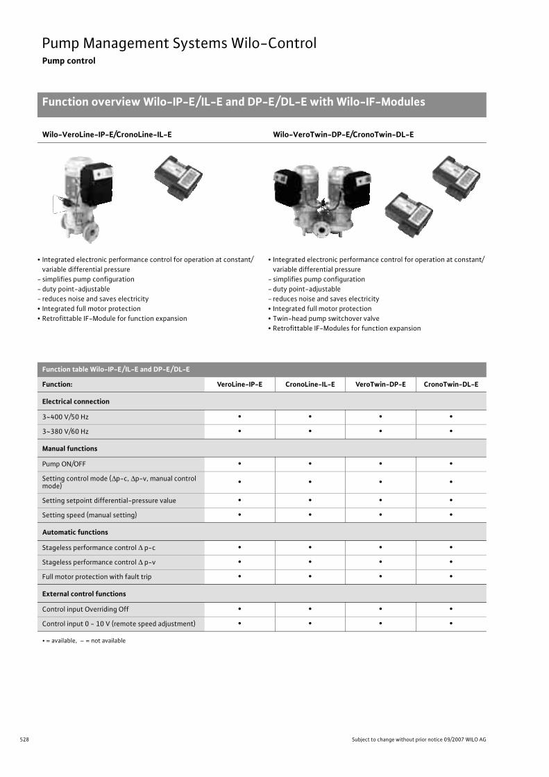
528 Subject to change without prior notice 09/2007 WILO AG
Pump Management Systems Wilo-ControlPump control
Function overview Wilo-IP-E/IL-E and DP-E/DL-E with Wilo-IF-Modules
Wilo-VeroLine-IP-E/CronoLine-IL-E Wilo-VeroTwin-DP-E/CronoTwin-DL-E
• Integrated electronic performance control for operation at constant/variable differential pressure
- simplifies pump configuration- duty point-adjustable- reduces noise and saves electricity• Integrated full motor protection• Retrofittable IF-Module for function expansion
• Integrated electronic performance control for operation at constant/variable differential pressure
- simplifies pump configuration- duty point-adjustable- reduces noise and saves electricity• Integrated full motor protection• Twin-head pump switchover valve• Retrofittable IF-Modules for function expansion
Function table Wilo-IP-E/IL-E and DP-E/DL-E
Function: VeroLine-IP-E CronoLine-IL-E VeroTwin-DP-E CronoTwin-DL-E
Electrical connection
3~400 V/50 Hz • • • •3~380 V/60 Hz • • • •
Manual functions
Pump ON/OFF • • • •Setting control mode (�p-c, �p-v, manual control mode) • • • •
Setting setpoint differential-pressure value • • • •Setting speed (manual setting) • • • •
Automatic functions
Stageless performance control � p-c • • • •Stageless performance control � p-v • • • •Full motor protection with fault trip • • • •
External control functions
Control input Overriding Off • • • •Control input 0 - 10 V (remote speed adjustment) • • • •
• = available, – = not available

529
Pump Management Systems Wilo-ControlPump control
Function overview Wilo-IP-E/IL-E and DP-E/DL-E with Wilo-IF-Modules
Wilo Catalogue A1 - 50 Hz - Circulating Pumps in Glandless Design
Hea
ting,
Air-
cond
ition
ing,
Co
olin
gSe
cond
ary
Hot W
ater
Circ
ulat
ion
Sola
r The
rmal
, Geo
ther
mal
En
ergy
Sys
tem
sSe
rvic
e/Ac
cess
orie
s, S
yste
ms
Switc
hgea
rs a
nd C
ontr
ol D
evic
esPu
mp
Man
agem
ent S
yste
ms
Function table Wilo-IP-E/IL-E and DP-E/DL-E (continued)
Function: VeroLine-IP-E CronoLine-IL-E VeroTwin-DP-E CronoTwin-DL-E
Signalling and display functions
Collective fault signal • • • •Collective run signal • • • •Fault signal light • • • •IR communication run signal light • • • •Fault code • • • •LC display for indicating pump data • • • •
Data exchange
Infrared interface for wireless data exchange with the Wilo-IR-Module/ IR-Monitor operating and serv-ice unit
• • • •
Serial digital PLR interface for connection to BA building automation via Wilo interface converter or company-specific coupling module
• 1) • 1) • 1) • 2)
Serial digital LON interface for connection to a LONWorks network • 3) • 3) • 3) • 4)
Serial digital CAN interface for connection to a CAN bus system • 5) – • 5) –
Dual pump management(2 x single-head or 1 x twin-head pump)
Main/standby operation (automatic. fault-actuated switchover/time-sensi-tive pump duty cycling)
• • • •
Duty/assist mode (peak-load cut-in and out) • • • •
• = available, – = not available
1) With 1 pc. IF-Module PLR2) With 2 pc. IF-Modules PLR/PLR3) With 1 pc. IF-Module LON4) With 2 pc. IF-Modules LON/PLR5) With 1 piece IF-Module CAN

530 Subject to change without prior notice 09/2007 WILO AG
Pump Management Systems Wilo-ControlPump control
Wilo-IF-Modules for single-head pumps
1 x Wilo-IF-Module PLR
Plug-in module for single-head pumps of the Wilo-TOP-E and Wilo-VeroLine-IP-E/CronoLine-IL-E series with infrared interface
>Additional functions• Serial digital PLR interface for connection to BA building automation via- Wilo interface converters or- Company-specific coupling modules• Transfer of the following data items as control commands to the
pump:- Control mode �p-c - Setpoint delivery head/speed- Pump ON/OFF- Setback operation• Transfer of the following data items as signals from the pump:- Actual value, delivery head- Actual value, volume flow- Actual value, power consumption- Actual value, power output- Actual value, motor current- Operating hours- Actual value, speed- Detailed fault reports- Status reports• Twin-head pumps interface DP for integrated dual pump manage-
ment of 2 x single-head or 1 x twin-head pump (see Wilo-IF-Module for twin-head pumps)
Terminal diagrams
PLR
DP L N PE SSM1~230 V
Wilo-TOP-EWilo-IF module PLR
Wilo interface converter orcompany specific coupling module
0...10V In
Ext.off P1 ≥ 500 W (P2 ≥ 350 W)
+24V
Wilo-IF-module PLR
Wilo interface converter orcompany speci�c coupling module
0/4...20 mAAux, no function
23 +24 V
PE L1 L2 L33~400V
1 0...10 V
Ext.off
Wilo-IL-E
DP
PLR
SBM
SSM
Wilo-IF-module PLR
Wilo interface converter orcompany speci�c coupling module
0/4...20 mAAux, no function
2
HL MP
3 +24 V PE L1 L2 L33~400V
1 0...10 V
Ext.off
Wilo-IP-E
DP
PLR
SBM
SSM

531
Pump Management Systems Wilo-ControlPump control
Wilo-IF-Module for single-head pumps
Wilo Catalogue A1 - 50 Hz - Circulating Pumps in Glandless Design
Hea
ting,
Air-
cond
ition
ing,
Co
olin
gSe
cond
ary
Hot W
ater
Circ
ulat
ion
Sola
r The
rmal
, Geo
ther
mal
En
ergy
Sys
tem
sSe
rvic
e/Ac
cess
orie
s, S
yste
ms
Switc
hgea
rs a
nd C
ontr
ol D
evic
esPu
mp
Man
agem
ent S
yste
ms
1 x Wilo-IF-Module LON
Plug-in module for LON compatible single-head pumps of the Wilo-TOP-E and Wilo-VeroLine-IP-E/CronoLine-IL-E series with infrared interface.
> Additional functions• Serial digital LON interface for connection to LONWorks networks.
Transfer of the following data items as control commands to the pump:
- Operating mode- Setpoint- Data from external sensors• Transfer of the following data items as signals from the pump:- Hydraulic operating data- Electrical operating data- Status reports- Fault signals• Twin-head pumps interface DP for integrated dual pump manage-
ment of 2 x single-head or 1 x twin-head pump (see Wilo-IF-Modules for twin-head pumps)
> Standards• LONMark Application Layer Interoperability Guidelines version 3.2• LONMark Layers 1-6 Interoperability Guidelines 3.0• LONMark Functional Profile “Pump controller Object for HVAC Appli-
cations” (8120_10.pdf)
> Delivery statusThe LON IF-Module is supplied as “Application unconfigured” in line with LONMark Application Layer Interoperability Guidelines.
> DocumentationWe make the following documentation available to you on our homepage www.wilo.com (- Products, - Wilo switchgears):LONMark Functional Profile “Pump controller Object for HVAC Appli-cations” (8120_10.pdf)
• Download application over network: *.NXE/*.APB• External interface files: *.XIF/*.XFB• Device resource files: *.ENU/*.FMT/*.FPT/
*.TYP
Terminal diagram
Wilo-IF-module LON*
* The picture does not showthe actual position of the terminals
LONWorks network
0/4...20 mAAux, no function
23 +24 V
PE L1 L2 L33~400V
1 0...10 V
Ext.off
Wilo-IL-E
DP
LON
SBM
SSM
LON
DP L N PE SSM1~230 V
Wilo-TOP-EWilo-IF module LON*
LONWorks network
0...10V In
Ext.off+24V
* The picture does not showthe actual position of the terminals
P1 � 500 W (P2 � 350 W)
Wilo-IF-module LON*
0/4...20 mAAux, no function
2
HL MP
3 +24 V PE L1 L2 L33~400V
1 0...10 V
Ext.off
Wilo-IP-E
DP
LON
SBM
SSM
* The picture does not showthe actual position of the terminals
LONWorks network

532 Subject to change without prior notice 09/2007 WILO AG
Pump Management Systems Wilo-ControlPump control
Wilo-IF-Module for single-head pumps
1 x Wilo-IF-Module CAN
Plug-in module for single-head pumps of the Wilo-VeroLine-IP-E series with infrared interface.
>Additional functions• Serial, digital CAN interface for connection to a CAN bus system• Transfer of following data items to the pump:- Operating mode- Setpoints for the selected operating mode- Configuration parameters• Transmission of the following data items as signals from the pump:- Hydraulic operating data- Electrical operating data- Statistical values- Status reports- Warning/fault/service messages- Type-specific parameters
>Standards• The interface CAN fulfils ISO 11898-2• The interface CAN fulfils the CANopen Standard CiA DS 301
version 4.0.2
>Scope of delivery• IF-Module CAN• CD-ROM with Installation and operating instructions and CAN proto-
col documentation• EMV cable connection PG7• EMV cable connection PG9
>Accessories- BusBox for cabling with short spur lines- CAN bus line in various lengths
>DocumentationThe protocol documentation has been made available to you on our homepage www.wilo.com.
Terminal diagram
Wilo-IF-module CAN
0/4...20 mAAux, no function
2
HL MP
3 +24 V PE L1 L2 L33~400V
1 0...10 V
Ext.off
Wilo-IP-E
CAN-LCAN-HCAN-LCAN-H WH
BNWHBN
CAN bus system (shielded cable)
CAN bus system(shielded cable)
SBM
SSM
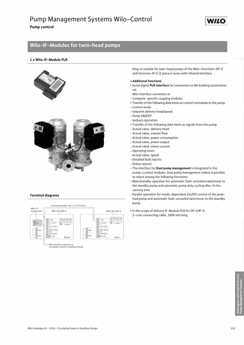
533
Pump Management Systems Wilo-ControlPump control
Wilo-IF-Modules for twin-head pumps
Wilo Catalogue A1 - 50 Hz - Circulating Pumps in Glandless Design
Hea
ting,
Air-
cond
ition
ing,
Co
olin
gSe
cond
ary
Hot W
ater
Circ
ulat
ion
Sola
r The
rmal
, Geo
ther
mal
En
ergy
Sys
tem
sSe
rvic
e/Ac
cess
orie
s, S
yste
ms
Switc
hgea
rs a
nd C
ontr
ol D
evic
esPu
mp
Man
agem
ent S
yste
ms
1 x Wilo-IF-Module PLR
Plug-in module for twin-head pumps of the Wilo-VeroTwin-DP-E and VeroLine-IP-E (2 pieces) series with infrared interface
> Additional functions• Serial digital PLR interface for connection to BA building automation
via- Wilo interface converters or- Company-specific coupling modules• Transfer of the following data items as control commands to the pump:- Control mode - Setpoint delivery head/speed- Pump ON/OFF- Setback operation• Transfer of the following data items as signals from the pump:- Actual value, delivery head- Actual value, volume flow- Actual value, power consumption- Actual value, power output- Actual value, motor current- Operating hours- Actual value, speed- Detailed fault reports- Status reports- The interface for Dual pump management is integrated in the
pump's control modules. Dual pump management makes it possible to select among the following functions:
- Main/standby operation for automatic fault-actuated switchover to the standby pump and automatic pump duty cycling after 24 hrs. running time
- Parallel operation for needs-dependent On/Off control of the peak-load pump and automatic fault-actuated switchover to the standby pump
• In the scope of delivery IF-Module PLR for DP-E/IP-E:2-core connecting cable, 1800 mm long
Terminal diagrams
PLR PE L1 L2 L33~400 V
Wilo-DP-E/IP-EWilo-IF-module PLR
Wilo interface converter ora company-speci�c coupling module.
SBM
SSM
3 +24 V21 0...10 V
0/4...20 mAAux, no function
Ext.off Master
PE L1 L2 L33~400 V
SBM
SSM
3 +24 V21 0...10 V
0/4...20 mAAux, no function
Ext.off Slave
Connecting cable, min. 2 x 0.75 mm2,2
Wilo-DP-E/IP-E
H MP MPLHL
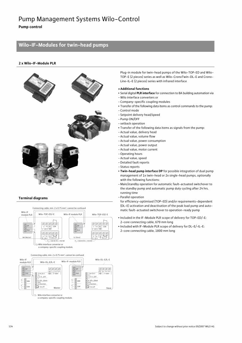
534 Subject to change without prior notice 09/2007 WILO AG
Pump Management Systems Wilo-ControlPump control
Wilo-IF-Modules for twin-head pumps
2 x Wilo-IF-Module PLR
Plug-in module for twin-head pumps of the Wilo-TOP-ED and Wilo-TOP-E (2 pieces) series as well as Wilo-CronoTwin-DL-E and Crono-Line-IL-E (2 pieces) series with infrared interface
>Additional functions• Serial digital PLR interface for connection to BA building automation via- Wilo interface converters or- Company-specific coupling modules• Transfer of the following data items as control commands to the pump:- Control mode - Setpoint delivery head/speed- Pump ON/OFF- setback operation• Transfer of the following data items as signals from the pump:- Actual value, delivery head- Actual value, volume flow- Actual value, power consumption- Actual value, power output- Actual value, motor current- Operating hours- Actual value, speed- Detailed fault reports- Status reports• Twin-head pump interface DP for possible integration of dual pump
management of 1x twin-head or 2x single-head pumps, optionally with the following functions:
- Main/standby operation for automatic fault-actuated switchover to the standby pump and automatic pump duty cycling after 24 hrs. running time
- Parallel operation for efficiency-optimised (TOP-ED) and/or requirements-dependent (DL-E) activation and deactivation of the peak load pump and auto-matic fault-actuated switchover to operation-ready pump
• Included in the IF-Module PLR scope of delivery for TOP-ED/-E:2-core connecting cable, 670 mm long
• Included with IF-Module PLR scope of delivery for DL-E/-IL-E:2-core connecting cable, 1800 mm long
Terminal diagrams
PLR
DP L N PE
1~230 V
0...10 V In
PLR
DP L N PE
1~230 V
0...10 V In
SSMSSM
Wilo-IF module PLR Wilo-TOP-ED/-E Wilo-IF module PLR
Wilo interface converter or a company-specific coupling module.
P1 � 500 W (P2 � 350 W) P1
� 500 W (P2 � 350 W)
Ext.offExt.off+24V
+24VMA (Master) SL (Slave)
Wilo-TOP-ED/-E
Connecting cable, min. 2 x 0.75 mm2, cannot be confused
Master Slave
3 +24 V21 0...10V
0/4...20mAAux, no function
23 +24 V
0/4...20mA
PE L1 L2 L3 PE L1 L2 L33~400V 3~400V
DP
PLR
DP
PLR
SBM
SSM
SBM
SSM
1 0...10V
Connecting cable, min. 2 x 0.75 mm2, cannot be confused
Wilo-IF module PLR Wilo-DL-E/IL-E Wilo-IF-module PLR
Wilo interface converter or a company-specific coupling module.
Wilo-DL-E/IL-E
Ext.offExt.off
Aux, no function

535
Pump Management Systems Wilo-ControlPump control
Wilo-IF-Module for twin-head pumps
Wilo Catalogue A1 - 50 Hz - Circulating Pumps in Glandless Design
Hea
ting,
Air-
cond
ition
ing,
Co
olin
gSe
cond
ary
Hot W
ater
Circ
ulat
ion
Sola
r The
rmal
, Geo
ther
mal
En
ergy
Sys
tem
sSe
rvic
e/Ac
cess
orie
s, S
yste
ms
Switc
hgea
rs a
nd C
ontr
ol D
evic
esPu
mp
Man
agem
ent S
yste
ms
1 x Wilo-IF-Module LON
Plug-in module for LON compatible twin-head pumps of the Wilo-VeroTwin-DP-E and Wilo-VeroLine-IP-E (2 pieces) series with infrared interface. The functions of the “LON” module are applicable to the entire twin-head pump.
> Additional functions• Serial digital LON interface for connection to LONWorks networks.
In the LONWorks network, data items are transmitted for the twin-head pump as a complete single unit; there is no differentiation between Master and Slave.
• Transfer of the following data items as control commands to the pump:- Operating mode- Setpoint- Data from external sensors• Transfer of the following data items as signals from the pump:- Hydraulic operating data- Electrical operating data- Status reports- Fault signals• The interface for Dual pump management is integrated in the
pump's control modules. Dual pump management makes it possible to select among the following functions:
- Main/standby operation for automatic fault-actuated switchover to the standby pump and automatic pump duty cycling after 24 hrs. running time
- Parallel operation for needs-dependent On/Off control of the peak-load pump and automatic fault-actuated switchover to the standby pump
> Standards• LONMark Application Layer Interoperability Guidelines version 3.2• LONMark Layers 1-6 Interoperability Guidelines 3.0• LONMark Functional Profile “Pump controller Object for HVAC
Applications” (8120_10.pdf)
> Delivery statusThe LON IF-Module is supplied as “Application unconfigured” in line with LONMark Application Layer Interoperability Guidelines.
> DocumentationWe make the following documentation available to you on our homepage www.wilo.com (- Products, - Wilo switchgears): LONMark Functional Profile “Pump controller Object for HVAC Applications” (8120_10.pdf)
• Download application over network: *.NXE/*.APB• External interface files: *.XIF/*.XFB• Device resource files: *.ENU/*.FMT/*.FPT/
*.TYP
Terminal diagrams
LON PE L1 L2 L33~400 V
Wilo-DP-E/IP-EWilo-IF-module LON*
LONWorks network
SBM
SSM
3 +24 V21 0...10 V
0/4...20 mAAux, no function
Ext.off Master
PE L1 L2 L33~400 V
SBM
SSM
3 +24 V21 0...10 V
0/4...20 mAAux, no function
Ext.off Slave
Connecting cable, min. 2 x 0,75 mm2
Wilo-DP-E/IP-E
H MP MPLHL

536 Subject to change without prior notice 09/2007 WILO AG
Pump Management Systems Wilo-ControlPump control
Wilo-IF-Module for twin-head pumps
Wilo-IF-Module 1 x LON and 1 x PLR
Plug-in module for LON-compatible twin-head pumps of the Wilo-TOP-ED and Wilo-TOP-E (2 pieces) series as well as Wilo-CronoTwin-DL-E and CronoLine-IL-E (2 pieces) series with infrared interface.For dual pump management a PLR module is required in addition to the LON function module.The functions of the “LON” module are applicable to the entire twin-head pump.
>Additional functions• Serial digital LON interface for connection to LONWorks networks.
In the LONWorks network, data items are transmitted for the twin-head pump as a complete single unit; there is no differentiation between Master and Slave.
• Transfer of the following data items as control commands to the pump:- Operating mode- Setpoint- Data from external sensors• Transfer of the following data items as signals from the pump:- Hydraulic operating data- Electrical operating data- Status reports- Fault signals• Twin-head pump interface DP for possible integration of dual pump
management of 1x twin-head or 2x single-head pumps, optionally with the following functions:
- Main/standby operation for automatic fault-actuated switchover to the standby pump and automatic pump duty cycling after 24 hrs. running time
- Duty/assist mode for efficiency-optimised On/Off control of the peak-load pump and automatic fault-actuated switchover to the standby pump
• Included in the IF-Module PLR scope of delivery for TOP-ED/-E:2-core connecting cable, 670 mm long
• Included with IF-Module PLR scope of delivery for DL-E/-IL-E:2-core connecting cable, 1800 mm long
>Standards• LONMark Application Layer Interoperability Guidelines version 3.2• LONMark Layers 1-6 Interoperability Guidelines 3.0• LONMark Functional Profile “Pump controller Object for HVAC
Applications” (8120_10.pdf)
>Delivery statusThe LON IF-Module is supplied as “Application unconfigured” in line with LONMark Application Layer Interoperability Guidelines.
>DocumentationWe make the following documentation available to you on our homepage www.wilo.com (- Products, - Wilo switchgears): LONMark Functional Profile “Pump controller Object for HVAC Applications” (8120_10.pdf)
• Download application over network: *.NXE/*.APB• External interface files: *.XIF/*.XFB• Device resource files: *.ENU/*.FMT/*.FPT/
*.TYP
Terminal diagrams
LON
DP L N PE SSM
1~230 V
Wilo-TOP-ED/-EWilo-IFmodule LON*
LONWorks network
0...10 V In
Ext.off+24V
PLR
DP L N PE SSM
1~230 V
0...10 V Ext.off
Connecting cable, min. 2 x 0,75 mm2, lock-protected
Wilo-IF module PLR Wilo-TOP-ED/-E
MA (Master) SL (Slave)
* Illustration does not reflect the actual position of the terminals
In
+24V
P1� 500 W (P2� 350 W) P1� 500 W (P2� 350 W)
LON
DP
PE L1 L2 L33~400 V
Wilo-DL-E/-IL-E
Wilo-IFmoduleLON*
LONWorks network
SBM
SSM
3 +24 V21 0...10 V
0/4...20mAAux,without function
Ext.offMaster
PLR
DP
PE L1 L2 L33~400 V
Wilo-IF module PLR
SBM
SSM
3 +24 V21 0...10 V
0/4...20mAAux, without function
Ext.offSlave
Connecting cable, min. 2 x 0,75 mm2, lock-protected
Wilo-DL-E/-IL-E
* Illustration does not reflect the actual position of the terminals

537
Pump Management Systems Wilo-ControlPump control
Wilo-IF-Module for twin-head pumps
Wilo Catalogue A1 - 50 Hz - Circulating Pumps in Glandless Design
Hea
ting,
Air-
cond
ition
ing,
Co
olin
gSe
cond
ary
Hot W
ater
Circ
ulat
ion
Sola
r The
rmal
, Geo
ther
mal
En
ergy
Sys
tem
sSe
rvic
e/Ac
cess
orie
s, S
yste
ms
Switc
hgea
rs a
nd C
ontr
ol D
evic
esPu
mp
Man
agem
ent S
yste
ms
1 x Wilo-IF-Module CAN
Plug-in module for twin-head pumps of the Wilo-VeroTwin-DP-E and Wilo-VeroLine-IP-E series with infrared interface.
> Additional functions• Serial, digital CAN interface for connection to a CAN bus system• Transfer of following data items to the pump:- Operating mode- Setpoints for the selected operating mode- Configuration parameters• Transmission of the following data items as signals from the pump:- Hydraulic operating data- Electrical operating data- Statistical values- Status reports- Warning/fault/service messages- Type-specific parameters• The interface for Dual pump management is integrated in the
pump's control modules. Dual pump management makes it possible to select among the following functions:
- Main/standby operation for automatic fault-actuated switchover to the standby pump and automatic pump duty cycling after 24 hrs. running time
- Parallel operation for needs-dependent On/Off control of the peak-load pump and automatic fault-actuated switchover to the standby pump
> Standards• The interface CAN fulfils ISO 11898-2• The interface CAN fulfils the CANopen Standard CiA DS 301
version 4.0.2
> Scope of delivery• IF-Module CAN• CD-ROM with Installation and operating instructions and CAN pro-
tocol documentation• EMV cable connection PG7• EMV cable connection PG9
> Accessories- BusBox for cabling with short spur lines- CAN bus line in various lengths
> DocumentationThe protocol documentation has been made available to you on our homepage www.wilo.com.
Terminal diagrams
LON PE L1 L2 L33~400 V
Wilo-DP-E/IP-EWilo-IF-module CAN
CAN bus system
SBM
SSM
3 +24 V21 0...10 V
0/4...20 mAAux, no function
Ext.off Master
PE L1 L2 L33~400 V
SBM
SSM
3 +24 V21 0...10 V
0/4...20 mAAux, no function
Ext.off Slave
Connecting cable, min. 2 x 0,75 mm2
Wilo-DP-E/IP-E
H MP MPLHL

538 Subject to change without prior notice 09/2007 WILO AG
Pump Management Systems Wilo-ControlPump control
Function overview Wilo-Protect-Module
Standard single-head pumps:Wilo-TOP-S/-TOP-Z/-TOP-RL/-SE series
Standard twin-head pumps:Wilo-TOP-SD/-SE-TW series
• 3 speed stages • 2 speed stages for the series TOP-S, 1~230 V, P2 � 350 W• Blocking current-proof or with full motor protection• Thermal insulation as standard• Retrofittable Protect module for standard pumps for supplementing
existing functions• For secondary hot water circulation systems on TOP-Z
• 3 speed stages• 2 speed stages for the series TOP-SD, 1~230 V, P2 � 350 W• Blocking current-proof or with full motor protection• Twin-head pump switchover valve with delay• Retrofittable Protect modules for standard pumps for supplementing
existing functions
Function table TOP-S /-Z/-SD/-RL/-SE/-SE-TW
Function: Single-head pump Wilo-TOP-S/-TOP-Z
Wilo-TOP-RL/-SE
Twin-head pump Wilo-TOP-SD/-SE-TW
1~ 3~ 1~ 3~
PumpPump with
Protect-Module C
PumpPump with
Protect-Module C
Pump
Pump with 2 pcs. Pro-tect-Mod-
ules C
Pump
Pump with 2 pcs. Pro-tect-Mod-
ules C
Electrical connection
1~230 V/50 Hz • • – – • • – –
3~400 V/50 Hz – – • • – – • •3~230 V/50 Hz – – • – – – • –
Manual functions
3-stage variable speed control • 1) • • • • 1) • • •Reset button • 2) • • • • 2) • • •
Automatic functions
Motor protection • 3) • • 3) • • 3) • • 3) •Full motor protection with fault trip • 2) • • • • 2) • • •Blockage detection with fault trip – • – • – • – •
External control functions
External Off/On-switching by means of onsite potential-free NC contact – • – • – • – •
• = available, – = not available
1) Pumps with P2 � 350 W: 2-stage speed control2) Only pumps with P2 � 350 W3) P2 � 100 W: Pumps with internal protection against unacceptably high winding temperatures
P2 = 180 W: WSK, motor protection only in conjunction with relays

539
Pump Management Systems Wilo-ControlPump control
Function overview Wilo-Protect-Module
Wilo Catalogue A1 - 50 Hz - Circulating Pumps in Glandless Design
Hea
ting,
Air-
cond
ition
ing,
Co
olin
gSe
cond
ary
Hot W
ater
Circ
ulat
ion
Sola
r The
rmal
, Geo
ther
mal
En
ergy
Sys
tem
sSe
rvic
e/Ac
cess
orie
s, S
yste
ms
Switc
hgea
rs a
nd C
ontr
ol D
evic
esPu
mp
Man
agem
ent S
yste
ms
Signalling and display functions
Individual/collective fault signal, potential-free – • • 1) • – • • 1) •
Individual/collective operating signal, potential-free – • – • – • – •
Run signal light – • – • – • – •Fault light motor protection – • • • – • • •Fault light blockage – • – • – • – •Direction of rotation control – • • – • •
Dual pump management (2 single-head pumps)
Main/standby operation (automatic fault-actuated switchover/time-sen-sitive pump alteration)
– • – • – • – •
• = available, – = not available
1) Pumps with P2 � 350 W: 2-stage speed control2) Only pumps with P2 � 350 W3) P2 � 100 W: Pumps with internal protection against unacceptably high winding temperatures
P2 = 180 W: WSK, motor protection only in conjunction with relays
Function table TOP-S /-Z/-SD/-RL/-SE/-SE-TW
Function: Single-head pump Wilo-TOP-S/-TOP-Z
Wilo-TOP-RL/-SE
Twin-head pump Wilo-TOP-SD/-SE-TW
1~ 3~ 1~ 3~
PumpPump with
Protect-Module C
PumpPump with
Protect-Module C
Pump
Pump with 2 pcs. Pro-tect-Mod-
ules C
Pump
Pump with 2 pcs. Pro-tect-Mod-
ules C
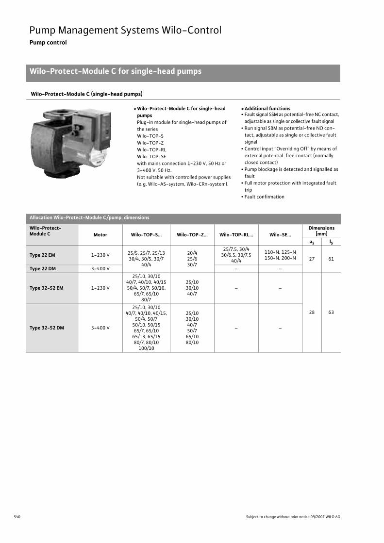
540 Subject to change without prior notice 09/2007 WILO AG
Pump Management Systems Wilo-ControlPump control
Wilo-Protect-Module C for single-head pumps
Wilo-Protect-Module C (single-head pumps)
> Wilo-Protect-Module C for single-head pumpsPlug-in module for single-head pumps of the series Wilo-TOP-SWilo-TOP-ZWilo-TOP-RLWilo-TOP-SEwith mains connection 1~230 V, 50 Hz or 3~400 V, 50 Hz. Not suitable with controlled power supplies (e.g. Wilo-AS-system, Wilo-CRn-system).
> Additional functions• Fault signal SSM as potential-free NC contact,
adjustable as single or collective fault signal• Run signal SBM as potential-free NO con-
tact, adjustable as single or collective fault signal
• Control input “Overriding Off” by means of external potential-free contact (normally closed contact)
• Pump blockage is detected and signalled as fault
• Full motor protection with integrated fault trip
• Fault confirmation
Allocation Wilo-Protect-Module C/pump, dimensions
Wilo-Protect-Module C Motor Wilo-TOP-S... Wilo-TOP-Z... Wilo-TOP-RL… Wilo-SE…
Dimensions [mm]
a5 l5
Type 22 EM 1~230 V 25/5, 25/7, 25/1330/4, 30/5, 30/7
40/4
20/425/630/7
25/7.5, 30/430/6.5, 30/7.5
40/4
110-N, 125-N150-N, 200-N 27 61
Type 22 DM 3~400 V – –
Type 32-52 EM 1~230 V
25/10, 30/1040/7, 40/10, 40/1550/4, 50/7, 50/10,
65/7, 65/1080/7
25/1030/1040/7
– –
28 63
Type 32-52 DM 3~400 V
25/10, 30/1040/7, 40/10, 40/15,
50/4, 50/750/10, 50/1565/7, 65/10
65/13, 65/1580/7, 80/10
100/10
25/1030/1040/750/7
65/1080/10
– –
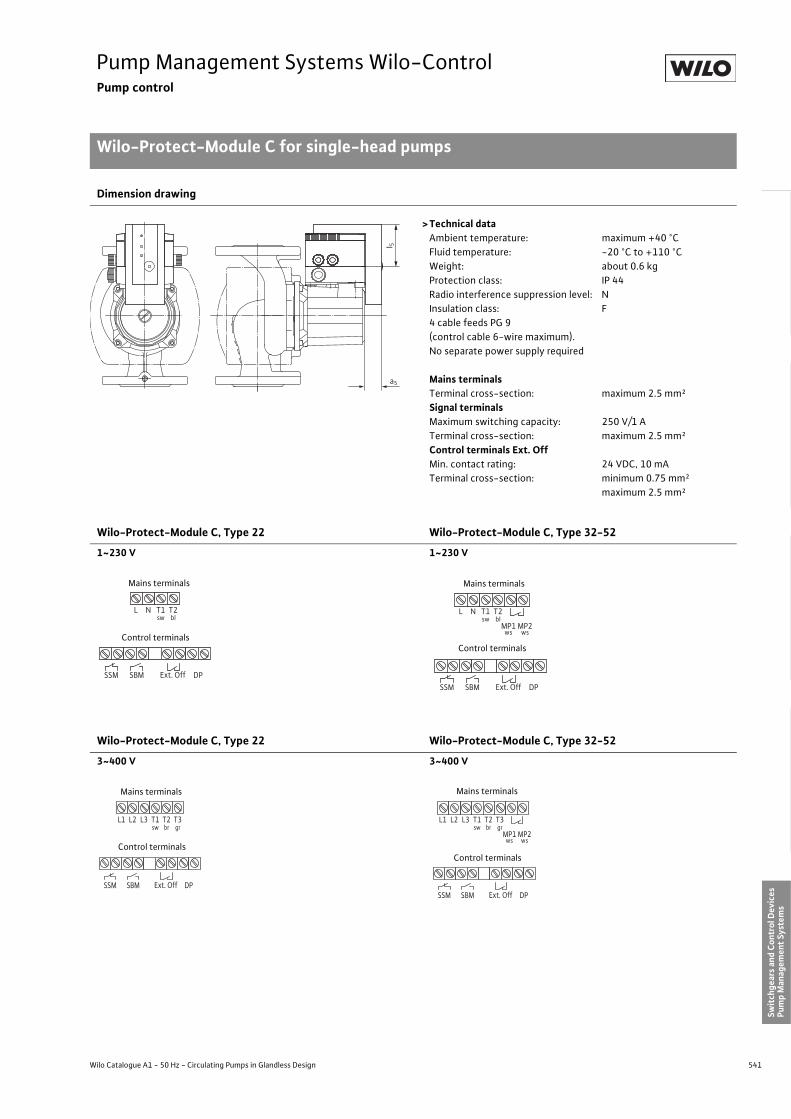
541
Pump Management Systems Wilo-ControlPump control
Wilo-Protect-Module C for single-head pumps
Wilo Catalogue A1 - 50 Hz - Circulating Pumps in Glandless Design
Hea
ting,
Air-
cond
ition
ing,
Co
olin
gSe
cond
ary
Hot W
ater
Circ
ulat
ion
Sola
r The
rmal
, Geo
ther
mal
En
ergy
Sys
tem
sSe
rvic
e/Ac
cess
orie
s, S
yste
ms
Switc
hgea
rs a
nd C
ontr
ol D
evic
esPu
mp
Man
agem
ent S
yste
ms
Dimension drawing
> Technical dataAmbient temperature: maximum +40 °CFluid temperature: -20 °C to +110 °CWeight: about 0.6 kgProtection class: IP 44Radio interference suppression level: NInsulation class: F4 cable feeds PG 9 (control cable 6-wire maximum).No separate power supply required
Mains terminalsTerminal cross-section: maximum 2.5 mm²Signal terminalsMaximum switching capacity: 250 V/1 ATerminal cross-section: maximum 2.5 mm²Control terminals Ext. OffMin. contact rating: 24 VDC, 10 mATerminal cross-section: minimum 0.75 mm²
maximum 2.5 mm²
Wilo-Protect-Module C, Type 22 Wilo-Protect-Module C, Type 32-52
1~230 V 1~230 V
Wilo-Protect-Module C, Type 22 Wilo-Protect-Module C, Type 32-52
3~400 V 3~400 V
a5l 5
L N T1sw
T2bl
SSM SBM DPExt. Off
Mains terminals
Control terminals
L N T1sw
T2bl
SSM SBM DPExt. Off
MP1 MP2ws ws
Mains terminals
Control terminals
L3 T1 sw
L1 L2 T2 br
T3 gr
SSM SBM DP Ext. Off
Mains terminals
Control terminals
SSM SBM DP Ext. Off
L3 T1 sw
L1 L2 T2 br
T3 gr
MP1 MP2 ws ws
Mains terminals
Control terminals

542 Subject to change without prior notice 09/2007 WILO AG
Pump Management Systems Wilo-ControlPump control
Wilo-Protect-Module C for twin-head pumps
Wilo-Protect-Module C (twin-head pumps)
> Wilo-Protect-Module C for twin-head pumpsPlug-in module for twin-head pumps of the series Wilo-TOP-SDWilo-SE-TWor 2 pieces single-head pumps of the series Wilo-TOP-SWilo-TOP-ZWilo-TOP-RLWilo-SEwith mains connection 1~230 V, 50 Hz or 3~400 V, 50 Hz. Not suitable with controlled power supplies (e.g. Wilo-AS-system, Wilo-CRn-system).
> Additional functions• Fault signal SSM as potential-free NC con-
tact, adjustable as single or collective fault signal
• Run signal SBM as potential-free NO con-tact, adjustable as single or collective oper-ating signal
• Control input “Overriding Off” by means of external potential-free contact (normally closed contact)
• Pump blockage is detected and signalled as fault
• Full motor protection with integrated fault trip
• Fault confirmation• Integrated dual pump management with the
functions- Main/standby operation with time-sensitive
(24 h) switchover from main to standby pump- Fault-sensitive switchover to operational
standby pump
Allocation Wilo-Protect-Module C/pump, dimensions
Wilo-Protect-Module C Motor Wilo-TOP-SD... Wilo-SE-TW...
Dimensions [mm]a5 l5
Type 22 EM 1~230 V30/532/7
32/1040/3
125-N-TW150-N-TW200-N-TW 27 61
Type 22 DM 3~400 V –
Type 32-52 EM 1~230 V40/7, 40/10, 40/15
50/7, 50/1065/10, 80/7
–
28 63
Type 32-52 DM 3~400 V
40/7, 40/10, 40/1550/7, 50/10, 50/15
65/10, 65/13, 65/1580/10
–
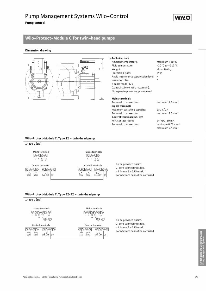
543
Pump Management Systems Wilo-ControlPump control
Wilo-Protect-Module C for twin-head pumps
Wilo Catalogue A1 - 50 Hz - Circulating Pumps in Glandless Design
Hea
ting,
Air-
cond
ition
ing,
Co
olin
gSe
cond
ary
Hot W
ater
Circ
ulat
ion
Sola
r The
rmal
, Geo
ther
mal
En
ergy
Sys
tem
sSe
rvic
e/Ac
cess
orie
s, S
yste
ms
Switc
hgea
rs a
nd C
ontr
ol D
evic
esPu
mp
Man
agem
ent S
yste
ms
Dimension drawing
> Technical dataAmbient temperature: maximum +40 °CFluid temperature: -20 °C to +110 °CWeight: about 0.6 kgProtection class: IP 44Radio interference suppression level: NInsulation class: F4 cable feeds PG 9 (control cable 6-wire maximum).No separate power supply required
Mains terminalsTerminal cross-section: maximum 2.5 mm²Signal terminalsMaximum switching capacity: 250 V/1 ATerminal cross-section: maximum 2.5 mm²Control terminals Ext. OffMin. contact rating: 24 VDC, 10 mATerminal cross-section: minimum 0.75 mm²
maximum 2.5 mm²
Wilo-Protect-Module C, Type 22 – twin-head pump
1~230 V (EM)
Wilo-Protect-Module C, Type 32-52 – twin-head pump
1~230 V (EM)
a5
l 5
L N T1sw
T2bl
SSM SBM DPExt. Off
L N T1sw
T2bl
SSM SBM DPExt. Off
Mains terminals
Control terminals
Mains terminals
Control terminals To be provided onsite:2-core connecting cable,minimum 2 x 0.75 mm²,connections cannot be confused
L N T1sw
T2bl
SSM SBM DPExt. Off
MP1 MP2ws ws
L N T1sw
T2bl
SSM SBM DPExt. Off
MP1 MP2ws ws
Mains terminals
Control terminals
Mains terminals
Control terminals
To be provided onsite:2-core connecting cable,minimum 2 x 0.75 mm²,connections cannot be confused
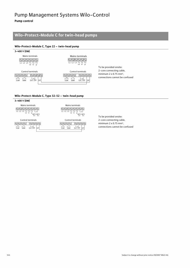
544 Subject to change without prior notice 09/2007 WILO AG
Pump Management Systems Wilo-ControlPump control
Wilo-Protect-Module C for twin-head pumps
Wilo-Protect-Module C, Type 22 – twin-head pump
3~400 V (DM)
Wilo-Protect-Module C, Type 32-52 – twin-head pump
3~400 V (DM)
SSM SBM DP Ext. Off SSM SBM DP Ext. Off
L3 T1 sw
L1 L2 T2 br
T3 gr
L3 T1 sw
L1 L2 T2 br
T3 gr
Mains terminals
Control terminals
Mains terminals
Control terminals
To be provided onsite:2-core connecting cable,minimum 2 x 0.75 mm²,connections cannot be confused
SSM SBM DP Ext. Off
L3 T1 sw
L1 L2 T2 br
T3 gr
MP1 MP2 ws ws
SSM SBM DP Ext. Off
L3 T1 sw
L1 L2 T2 br
T3 gr
MP1 MP2 ws ws
Mains terminals
Control terminals
Mains terminals
Control terminalsTo be provided onsite:2-core connecting cable,minimum 2 x 0.75 mm²,connections cannot be confused
545
Pump Management Systems Wilo-ControlPump control
Wilo Catalogue A1 - 50 Hz - Circulating Pumps in Glandless Design
Hea
ting,
Air-
cond
ition
ing,
Co
olin
gSe
cond
ary
Hot W
ater
Circ
ulat
ion
Sola
r The
rmal
, Geo
ther
mal
En
ergy
Sys
tem
sSe
rvic
e/Ac
cess
orie
s, S
yste
ms
Switc
hgea
rs a
nd C
ontr
ol D
evic
esPu
mp
Man
agem
ent S
yste
ms

546 Subject to change without prior notice 09/2007 WILO AG
Pump Management Systems Wilo-ControlControl Technology
Wilo-Control AnaCon
Wilo-Control AnaCon
Front view Dimension drawing
I 0 Bus Controller
EIB
Bus Controller
CAN
Bus Controller
AnaCon AnaCon
TOP-E Stratos
LON
I 0 I 0
Sensor
Sensor
Sensor
Sensor
Sensor
ma
0-10V off max min on 24V ssm ebm-ma ebm-sl
+-
mode
p-cp-v
n-c
set pointAna
Con
100%
0%
0-10V disable
set
sl 0/0/0
power
+-
pump rs 23224 V
DC
50m
A
1446 90
87 33
58
15 10
148
8

547
Pump Management Systems Wilo-ControlControl Technology
Wilo-Control AnaCon
Wilo Catalogue A1 - 50 Hz - Circulating Pumps in Glandless Design
Hea
ting,
Air-
cond
ition
ing,
Co
olin
gSe
cond
ary
Hot W
ater
Circ
ulat
ion
Sola
r The
rmal
, Geo
ther
mal
En
ergy
Sys
tem
sSe
rvic
e/Ac
cess
orie
s, S
yste
ms
Switc
hgea
rs a
nd C
ontr
ol D
evic
esPu
mp
Man
agem
ent S
yste
ms
Wilo-Control AnaConThe Wilo-Control AnaCon interface converter is suitable for the uni-versal connection of communication-ready pumps with the interface PLR to onsite control and monitoring units with conventional incom-ing/outgoing channels. It is installed in the immediate vicinity of the monitoring unit on a DIN rail (DIN EN 50 022-35) in a switch cabinet. The interface converter Wilo-Control AnaCon converts the two-wire connection of the serial digital interface PLR into a parallel interface with analogue signals and potential-free contacts.1 single-head or twin-head pump of the following Wilo series is linked to the BA via the Wilo-Control AnaCon interface converter:
- TOP-E/-ED (with IF-Module PLR)- Stratos/-D/-ZD (with Stratos IF-Module PLR)- VeroLine-IP-E/-DP-E (with IF-Module PLR)- CronoLine-IL-E/-DL-E (with IF-Module PLR)
Bidirectional communication between the pumps and the monitoring unit (BA) makes possible remote control of:
- Pump Off- Pump in control mode ON- Maximum speed- Minimum speed (setback operation)- Setpoint for differential pressure or speed
(control input analogue In 0 - 10 V)Bidirectional communication between the pumps and the monitoring unit (BA) makes possible remote query of:
- Collective fault signal- Individual run signal MA or individual pump- Individual run signal SL (twin-head pump only)
In addition to the remote control and the remote query, the interface converter Wilo-Control AnaCon also makes possible the local setting of:
-�p-c for constant differential pressure-�p-v for variable differential pressure- n-c for constant speed- Setpoint for differential pressure or speed- Enablement of the control input analogue In 0 - 10 V
The interface converter Wilo-Control AnaCon is equipped with LEDs for:- AnaCon operational state- Communication with the pump- Communication with interface RS 485- Collective fault signal- Individual run signal MA or individual pump- Individual run signal SL (twin-head pump only)
Technical data• Contact load- Collective fault signal
(potential-free changeover contact): maximum 250 VAC, 1 A- Individual run signal MA
(potential-free NO contact) maximum 250 VAC, 1 A- Individual run signal SL
(potential-free NO contact) maximum 250 VAC, 1 A- Potential-free NO contact
for function “Pump Off”: 24 VDC, 2.4 mA- Potential-free NO contact
for function “Control mode On”: 24 VDC, 2.4 mA
- Potential-free NO contactfor function “Maximum speed”: 24 VDC, 2.4 mA
- Potential-free NO contactfor function “Min. speed”: 24 VDC, 2.4 mA
• Supply voltage- Operating voltage: 24 VDC ± 25%- Current consumption: 40 mA
• Electromagnetic compatibility- Emitted interference: DIN EN 61000-6-3- Immunity to interference: DIN EN 61000-6-2
• Control input analogue In 0 - 10 V- Input resistance: >200 k�- Input protection: maximum +/- 48 VDC
• Interface PLR- Point-to-point interface with Wilo-specific hardware and Wilo-spe-
cific protocol- Two-wire connection with interchangeable cores (no shielded cable
necessary)- Maximum cable length: 200 m
Manual operation of the pump by means of the red button is not pos-sible if the pump is connected to the AnaCon.A temporary disruption of the interface connection to electronically controlled pumps with IR interface is possible with the IR-Monitor. The operation can then be controlled with the IR-Monitor. Interface communication is automatically restored after the IR connection is disconnected.

548 Subject to change without prior notice 09/2007 WILO AG
Pump Management Systems Wilo-ControlControl Technology
Wilo-Control DigiCon
Wilo-Control DigiCon
Front view Dimension drawing
I 0 Bus Controller
RS 485
Bus Controller
CAN
Bus Controller
DigiCon
Stratos-D Stratos
DigiCon
IP-E IL-ETOP-E TOP-ED
LON
I 0 I 0
4321
RSNON
65
pump 1 pump 2 pump 3 pump 4
mode
p-cp-v
n-c
set pointaddress
Dig
iCon
100%
0%
rs 485
1
1
2 3 4
power
+-
rs 485
a b BaudZ
rs 232
0/0/0
2
0/0/0
3
0/0/0
4
0/0/0
24 V
DC
50m
A
1446 90
87 33
58
15 10
148
8
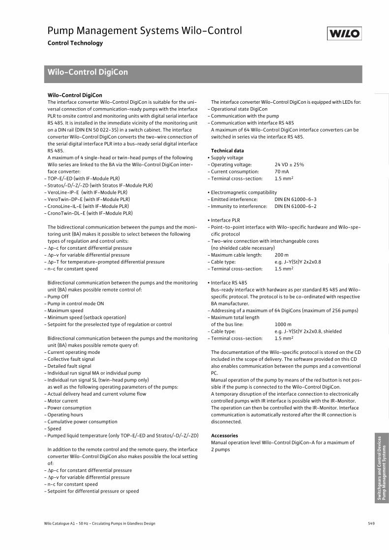
549
Pump Management Systems Wilo-ControlControl Technology
Wilo-Control DigiCon
Wilo Catalogue A1 - 50 Hz - Circulating Pumps in Glandless Design
Hea
ting,
Air-
cond
ition
ing,
Co
olin
gSe
cond
ary
Hot W
ater
Circ
ulat
ion
Sola
r The
rmal
, Geo
ther
mal
En
ergy
Sys
tem
sSe
rvic
e/Ac
cess
orie
s, S
yste
ms
Switc
hgea
rs a
nd C
ontr
ol D
evic
esPu
mp
Man
agem
ent S
yste
ms
Wilo-Control DigiConThe interface converter Wilo-Control DigiCon is suitable for the uni-versal connection of communication-ready pumps with the interface PLR to onsite control and monitoring units with digital serial interface RS 485. It is installed in the immediate vicinity of the monitoring unit on a DIN rail (DIN EN 50 022-35) in a switch cabinet. The interface converter Wilo-Control DigiCon converts the two-wire connection of the serial digital interface PLR into a bus-ready serial digital interface RS 485.A maximum of 4 single-head or twin-head pumps of the following Wilo series are linked to the BA via the Wilo-Control DigiCon inter-face converter:
- TOP-E/-ED (with IF-Module PLR)- Stratos/-D/-Z/-ZD (with Stratos IF-Module PLR)- VeroLine-IP-E (with IF-Module PLR)- VeroTwin-DP-E (with IF-Module PLR)- CronoLine-IL-E (with IF-Module PLR)- CronoTwin-DL-E (with IF-Module PLR)
The bidirectional communication between the pumps and the moni-toring unit (BA) makes it possible to select between the following types of regulation and control units:
-�p-c for constant differential pressure-�p-v for variable differential pressure-�p-T for temperature-prompted differential pressure- n-c for constant speed
Bidirectional communication between the pumps and the monitoring unit (BA) makes possible remote control of:
- Pump Off- Pump in control mode ON- Maximum speed- Minimum speed (setback operation)- Setpoint for the preselected type of regulation or control
Bidirectional communication between the pumps and the monitoring unit (BA) makes possible remote query of:
- Current operating mode- Collective fault signal- Detailed fault signal- Individual run signal MA or individual pump- Individual run signal SL (twin-head pump only)
as well as the following operating parameters of the pumps:- Actual delivery head and current volume flow- Motor current- Power consumption- Operating hours- Cumulative power consumption- Speed- Pumped liquid temperature (only TOP-E/-ED and Stratos/-D/-Z/-ZD)
In addition to the remote control and the remote query, the interface converter Wilo-Control DigiCon also makes possible the local setting of:
-�p-c for constant differential pressure-�p-v for variable differential pressure- n-c for constant speed- Setpoint for differential pressure or speed
The interface converter Wilo-Control DigiCon is equipped with LEDs for:- Operational state DigiCon- Communication with the pump- Communication with interface RS 485
A maximum of 64 Wilo-Control DigiCon interface converters can be switched in series via the interface RS 485.
Technical data• Supply voltage- Operating voltage: 24 VD ± 25%- Current consumption: 70 mA- Terminal cross-section: 1.5 mm2
• Electromagnetic compatibility- Emitted interference: DIN EN 61000-6-3- Immunity to interference: DIN EN 61000-6-2
• Interface PLR- Point-to-point interface with Wilo-specific hardware and Wilo-spe-
cific protocol- Two-wire connection with interchangeable cores
(no shielded cable necessary)- Maximum cable length: 200 m- Cable type: e.g. J-Y(St)Y 2x2x0.8- Terminal cross-section: 1.5 mm2
• Interface RS 485Bus-ready interface with hardware as per standard RS 485 and Wilo-specific protocol. The protocol is to be co-ordinated with respective BA manufacturer.
- Addressing of a maximum of 64 DigiCons (maximum of 256 pumps)- Maximum total length
of the bus line: 1000 m- Cable type: e.g. J-Y(St)Y 2x2x0.8, shielded- Terminal cross-section: 1.5 mm2
The documentation of the Wilo-specific protocol is stored on the CD included in the scope of delivery. The software provided on this CD also enables communication between the pumps and a conventional PC.Manual operation of the pump by means of the red button is not pos-sible if the pump is connected to the Wilo-Control DigiCon. A temporary disruption of the interface connection to electronically controlled pumps with IR interface is possible with the IR-Monitor. The operation can then be controlled with the IR-Monitor. Interface communication is automatically restored after the IR connection is disconnected.
AccessoriesManual operation level Wilo-Control DigiCon-A for a maximum of 2 pumps

550 Subject to change without prior notice 09/2007 WILO AG
Pump Management Systems Wilo-ControlControl Technology
Wilo-Control DigiCon-A
Wilo-Control DigiCon-A
Front view Dimension drawing
I 0 Bus Controller
RS 485
Bus Controller
CAN
Bus Controller
DigiCon DigiCon-A DigiCon-A
Stratos-D Stratos
DigiCon DigiCon-A DigiCon-A
IP-E IL-ETOP-E TOP-ED
LON
I 0 I 0
ma
0-10V off max min on 24V ssm ebm-ma ebm-sl
0-10V off max min on 24V ssm ebm-ma ebm-sl
+ -
+ -
Dig
iCon
-A
0-10V disable
0-10V disable
sl
1 1 1
ma sl
2 2 2
1446 90
87 33
58
15 10
148
8

551
Pump Management Systems Wilo-ControlControl Technology
Wilo-Control DigiCon-A
Wilo Catalogue A1 - 50 Hz - Circulating Pumps in Glandless Design
Hea
ting,
Air-
cond
ition
ing,
Co
olin
gSe
cond
ary
Hot W
ater
Circ
ulat
ion
Sola
r The
rmal
, Geo
ther
mal
En
ergy
Sys
tem
sSe
rvic
e/Ac
cess
orie
s, S
yste
ms
Switc
hgea
rs a
nd C
ontr
ol D
evic
esPu
mp
Man
agem
ent S
yste
ms
Wilo-Control DigiCon-AThe Wilo-Control DigiCon-A manual operation level makes possible the overriding control of pumps which are connected to Wilo-Control DigiCon interface converters.The manual operation level is installed on a DIN rail (DIN EN 50 022-35) and contacted with the Wilo-Control DigiCon interface converter by means of a lateral plug system. 2 manual operation levels for the overriding control of a maximum of 4 single-head or twin-head pumps can be connected to a Wilo-Control DigiCon.The Wilo-Control DigiCon-A manual operation level enables overrid-ing remote control via potential-free control contacts and an ana-logue signal with simultaneous bus communication:
- Pump Off- Pump in control mode ON- Maximum speed- Minimum speed (setback operation)- Setpoint for differential pressure or speed
(control input Analogue In 0 - 10 V)
The Wilo-Control DigiCon-A manual operation level enables remote queries via potential-free signalling contacts with simultaneous bus communication of:
- Collective fault signal- Individual run signal MA or individual pump- Individual run signal SL (twin-head pump only)
In addition to remote control and remote query, the Wilo-Control DigiCon-A manual operation level also enables
- Enablement of the control input Analogue In 0 - 10 V
The Wilo-Control DigiCon-A manual operation level is equipped with LEDs for:
- Operational state DigiCon-A- Collective fault signal (for each pump)- Individual run signal MA or individual pump (for each pump)- Individual run signal SL (twin-head pump only) (for each pump)
Technical data• Contact load- Collective fault signal
(potential-free changeover contact): maximum 250 VAC, 1 A- Individual run signal MA
(potential-free NO contact) maximum 250 VAC, 1 A- Individual run signal SL
(potential-free NO contact) maximum 250 VAC, 1 A- Potential-free NO contact
for function “Pump Off”: 24 VDC, 2.4 mA- Potential-free NO contact
for function “Control mode On”: 24 VDC, 2.4 mA- Potential-free NO contact
for function “Maximum speed”: 24 VDC, 2.4 mA- Potential-free NO contact
for function “Min. speed”: 24 VDC, 2.4 mA
• Supply voltage- Operating voltage: The DigiCon-A manual operation level
is supplied with voltage by DigiConvia the lateral plug system.
- Current consumption: 40 mA
• Electromagnetic compatibility- Emitted interference: DIN EN 61000-6-3- Immunity to interference: DIN EN 61000-6-2
• Control input analogue In 0 - 10 V- Input resistance: >200 k�- Input protection: maximum +/- 48 VDC
• Interface PLR- Point-to-point interface with Wilo-specific hardware and Wilo-spe-
cific protocol- Two-wire connection with interchangeable cores (no shielded cable
necessary)- Maximum cable length: 200 m
Manual operation of the pump by means of the red button is not pos-sible if the pump is connected to the Wilo-Control DigiCon. A temporary disruption of the interface connection to electronically controlled pumps with IR interface is possible with the IR-Monitor. The operation can then be controlled with the IR-Monitor. Interface communication is automatically restored after the IR connection is disconnected.

552 Subject to change without prior notice 09/2007 WILO AG
Pump Management Systems Wilo-ControlControl Technology
Accessories
Wilo-Control BusBox• Junction box for mounting a CAN bus system with linkup of the
nodes via short spur lines. The Wilo-Control BusBox requires no external power supply.
Technical data:- Protection class: IP 44
Fig.: Wilo-Control BusBox
Wilo-Control CAN bus wire• Shielded CAN bus wire 1 x 2 x 0.5, available in the lengths:- 10 m- 50 m - 100 m- 200 m• The cable is suitable for permanent placement inside buildings.
Technical data:- Number of cores: 2- Nominal cross-section: 0.5 mm2
- Characteristic impedance: 120 W- Loop resistance: maximum 186 W/km- Operating capacity: 60 pF/m
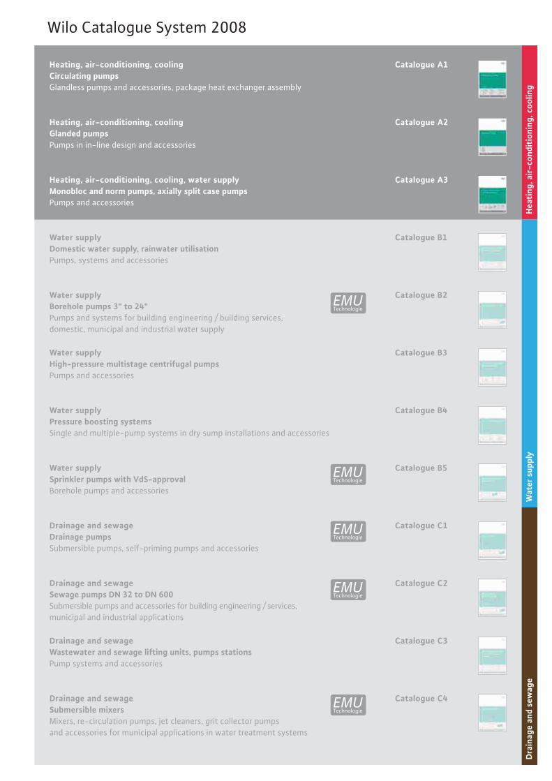
Heating, air-conditioning, coolingCirculating pumpsGlandless pumps and accessories, package heat exchanger assembly
Heating, air-conditioning, coolingGlanded pumpsPumps in in-line design and accessories
Heating, air-conditioning, cooling, water supplyMonobloc and norm pumps, axially split case pumpsPumps and accessories
Water supplyDomestic water supply, rainwater utilisationPumps, systems and accessories
Water supplyBorehole pumps 3" to 24"Pumps and systems for building engineering / building services,domestic, municipal and industrial water supply
Water supplyHigh-pressure multistage centrifugal pumpsPumps and accessories
Water supplySprinkler pumps with VdS-approvalBorehole pumps and accessories
Drainage and sewageDrainage pumpsSubmersible pumps, self-priming pumps and accessories
Drainage and sewageSewage pumps DN 32 to DN 600Submersible pumps and accessories for building engineering / services,municipal and industrial applications
Drainage and sewageWastewater and sewage lifting units, pumps stationsPump systems and accessories
Drainage and sewageSubmersible mixersMixers, re-circulation pumps, jet cleaners, grit collector pumps and accessories for municipal applications in water treatment systems
Catalogue A1
Catalogue A2
Catalogue A3
Catalogue B1
Catalogue B2
Catalogue B3
Catalogue B5
Water supplyPressure boosting systemsSingle and multiple-pump systems in dry sump installations and accessories
Catalogue B4
Catalogue C1
Catalogue C2
Catalogue C3
Catalogue C4
UMETechnologie
UMETechnologie
UMETechnologie
UMETechnologie
UMETechnologie
Hea
ting
, air
-con
diti
onin
g, c
oolin
gW
ater
sup
ply
Dra
inag
e an
d se
wag
e
Wilo Catalogue System 2008

WILO AGNortkirchenstraße 10044263 DortmundGermanyT +49 231 4102-0F +49 231 4102-7363www.wilo.com
AlgeriaBad Ezzouar, Dar El BeidaT +213 21 [email protected]
Armenia375001 YerevanT +374 10 [email protected]
Bosnia and Herzegovina71000 Sarajevo T +387 33 [email protected]
Georgia0177 TbilisiT +995 [email protected]
Macedonia1000 SkopjeT +389 2 [email protected]
Moldova2012 ChisinauT +373 2 [email protected]
Rep. MongoliaUlaanbaatarT +976 11 [email protected]
Tajikistan734025 DushanbeT +992 37 [email protected]
Turkmenistan744000 AshgabadT +993 12 [email protected]
Uzbekistan700046 [email protected]
January 2008
Wilo – International (Subsidiaries)
Wilo – International (Representation offices)
ArgentinaWILO SALMSONArgentina S.A.C1270ABE CiudadAutónoma de Buenos AiresT +54 11 [email protected]
AustriaWILO Handelsges. m.b.H.1230 WienT +43 5 [email protected]
Azerbaijan WILO Caspian LLC1065 BakuT +994 12 [email protected]
BelarusWILO Bel OOO220035 MinskT +375 17 [email protected]
BelgiumWILO SA/NV1083 GanshorenT +32 2 [email protected]
BulgariaWILO Bulgaria Ltd.1125 Sofia T +359 2 [email protected]
CanadaWILO Canada Inc. Calgary, Alberta T2A 5L4T +1 403 [email protected]
ChinaWILO China Ltd.101300 BeijingT +86 10 [email protected]
CroatiaWILO Hrvatska d.o.o. 10090 ZagrebT +38 51 [email protected]
Czech RepublicWILO Praha s.r.o.25101 CestliceT +420 234 [email protected]
DenmarkWILO Danmark A/S2690 KarlslundeT +45 70 [email protected]
EstoniaWILO Eesti OÜ12618 TallinnT +372 [email protected]
FinlandWILO Finland OY02330 EspooT +358 [email protected]
FranceWILO S.A.S.78390 Bois d'ArcyT +33 1 [email protected]
Great BritainWILO (U.K.) Ltd.DE14 2WJ Burton-Upon-TrentT +44 1283 [email protected]
GreeceWILO Hellas AG14569 Anixi (Attika)T +302 10 [email protected]
HungaryWILO Magyarország Kft2045 Törökbálint(Budapest)T +36 23 [email protected]
IrelandWILO Engineering Ltd.LimerickT +353 61 [email protected]
ItalyWILO Italia s.r.l.20068 PeschieraBorromeo (Milano)T +39 [email protected]
KazakhstanWILO Central Asia 050002 AlmatyT +7 3272 [email protected]
KoreaWILO Pumps Ltd. 621-807 GimhaeGyeongnamT +82 55 [email protected]
LatviaWILO Baltic SIA1019 RigaT +371 7 [email protected]
LebanonWILO SALMSON Lebanon12022030 El MetnT +961 4 [email protected]
LithuaniaWILO Lietuva UAB03202 VilniusT +370 5 [email protected]
The NetherlandsWILO Nederland b.v.1948 RC BeverwijkT +31 251 [email protected]
NorwayWILO Norge AS0901 OsloT +47 22 [email protected]
PolandWILO Polska Sp. z.o.o.05-090 RaszynT +48 22 [email protected]
PortugalBombas Wilo-SalmsonPortugal Lda.4050-040 PortoT +351 22 [email protected]
RomaniaWILO Romania s.r.l.077040 Com. ChiajnaJud. IlfovT +40 21 [email protected]
RussiaWILO Rus ooo123592 MoscowT +7 495 [email protected]
Saudi ArabiaWILO ME - RiyadhRiyadh 11465T +966 1 [email protected]
Serbia and MontenegroWILO Beograd d.o.o.11000 BeogradT +381 11 [email protected]
SlovakiaWILO Slovakia s.r.o.82008 Bratislava 28T +421 2 [email protected]
SloveniaWILO Adriatic d.o.o.1000 LjubljanaT +386 1 [email protected]
South AfricaSalmson South Africa1610 EdenvaleT +27 11 [email protected]
SpainWILO Ibérica S.A.28806 Alcalá de Henares(Madrid)T +34 91 [email protected]
SwedenWILO Sverige AB35246 VäxjöT +46 470 [email protected]
SwitzerlandEMB Pumpen AG4310 RheinfeldenT +41 61 [email protected]
TaiwanWILO-EMU Taiwan Co. Ltd.110 TaipehT +886 227 [email protected]
TurkeyWILO Pompa Sistemleri San. ve Tic. A.S.34530 IstanbulT +90 216 [email protected]
UkrainaWILO Ukraina t.o.w.01033 KiewT +38 044 [email protected]
VietnamPompes Salmson VietnamHo Chi Minh-Ville VietnamT +84 8 [email protected]
United Arab EmiratesWILO ME - DubaiDubaiT +971 4 [email protected]
USAWILO-EMU USA LLCThomasville, Georgia 31792T +1 229 [email protected]
USAWILO USA LLC Melrose Park, Illinois 60160T +1 708 [email protected]
Subject to change without prior notice. In appliance of our General Terms of Delivery and Service (see www.wilo.com)
W2924/3T/0709/GB/MP