technical bulletin - the mcilvaine company feedwater services..... 4 condensate services ..... 5...
TRANSCRIPT

Technical Bulletin
Combined Cycle Unit Applications
Experience In Motion

Combined Cycle Unit ApplicationsTable of Contents and Figures
Table of Contents PageIntroduction
................................................................................................. 1
Pump Recommendations Boiler Feedwater Services......................................................... 4Condensate Services ................................................................ 5Circulating Water Services ........................................................ 5Ancillary Services ..................................................................... 5Guidelines for Mechanical Seals ............................................... 5
CO2 Capture and SequestrationCO2 Capture .............................................................................. 6CO2 Transportation ................................................................... 7Sequestering ............................................................................. 7
Figures PageFigure 1 Simplified Combined Cycle Power Plant ........................ 1Figure 2 Combined Cycle Unit Power Plant ................................. 2Figure 3 Integrated Gasification Combined Cycle Power Plant .... 3Figure 4 Two-Turbine Combined Cycle Unit Pump Applications .. 4Figure 5 CO2 Recovery Unit ........................................................ 6Figure 6 A Post-Combustion CO2 Capture Unit............................ 6Figure 7 A Carbon Capture Unit in a Coal-Fired Power Plant ....... 6Figure 8 Overview of Geologic Storage Options .......................... 7
Combined Cycle Unit Applications
ii

1
Introduction
Combined Cycle Unit ApplicationsIntroduction
Driven largely by economic growth in developing countries, global energy demand is expected to surge more than one-third by 2030. Fossil fuels still continue to make up most of the mix with natural gas and coal accounting for a little more than 44% of electricity generation. (Source: International Energy Administration.)
The “Economist” magazine reports the world’s population currently consumes about 15 terawatts of energy annually. By 2030, global power consumption will likely rise to 30 terawatts. To put this in perspective, a terawatt is 1000 gigawatts and a gigawatt is the capacity of the very largest coal-fired power stations. A typical combined cycle power station generates 450 to 500 megawatts.
Advantages of Combined Cycle Power PlantsCombined cycle power plants have many advantages compared with other fossil fuel plants. (See Figure 1.) Chief among these is the fact that natural gas is a relatively clean burning fuel, emitting far less SOx, NOx, mercury and CO2 than coal. This is a significant benefit as movement toward carbon taxes grows globally. Other advantages include:
•Lower initial investment cost (about one half that of coal-fired plant: U.S. $1.0 billion per 550 mW vs. U.S. $ 2.0 billion)
•Shorter construction cycle•Smaller land parcels needed•Higher efficiency (58 to 60% vs. 38 to 42%)•Lower operating and maintenance costs• Faster return on investment•Easier permitting•Versatility
It should be noted that operating costs of combined cycle power plants are highly price sensitive to and dependent upon an abundant, reliable supply of natural gas. While coal is less expensive than natural gas, the cost associated with handling, processing and cleaning emissions are significantly higher than those related to natural gas. Furthermore, global environmental treaties and carbon-related taxes will almost certainly discourage the use of coal in favor of natural gas.
Before reviewing combined cycle processes in detail, it will be helpful to define several associated terms to avoid confusion.
First of all, do not confuse combined cycle with cogeneration. Combined cycle is an electric generating technology in which additional electricity is produced from otherwise lost waste heat exiting from gas turbines. The exiting heat is routed to a conventional boiler or to a heat recovery steam generator for utilization by a steam turbine in the production of electricity. The process significantly increases the efficiency of the electricity generating unit from 38 to 42% to 58 to 60%. “Cogen,” on the other hand, is the simultaneous production of electricity and steam from the same energy source. For example, burning natural gas produces electricity and heat. The heat is captured and converted to steam for space heating or industrial process use.
Heat Recovery Steam Generator
Condensate Extraction Pump
Circulation WaterPump
Gas Turbine
Condenser
GeneratorSteam
Turbine
Generator
Process Steam
Deaerator/LP DrumBoiler Feed
Pumps
Figure 1 – Simplified Combined Cycle Power Plant
2
Combined Cycle Unit ApplicationsIntroduction
EvaporativeCooler
EmissionsReductionCatalyst
Heat RecoverySteam Generator I.A
(HRSG)
Mist Eliminator
180 000 kW
SMUD Substation
GeneratorNo.2
Filter
Air
Generator No.1Compressor Turbine
SteamTurbine
Make-upWater
Stack
Steam Drum(LP, IP, HP)Natural Gas
Fuel
SteamCondenser
Condensate Pump
Blowdown to Treatment
Cooling Tower
CirculatingWater Pump
Boiler Feed Pump
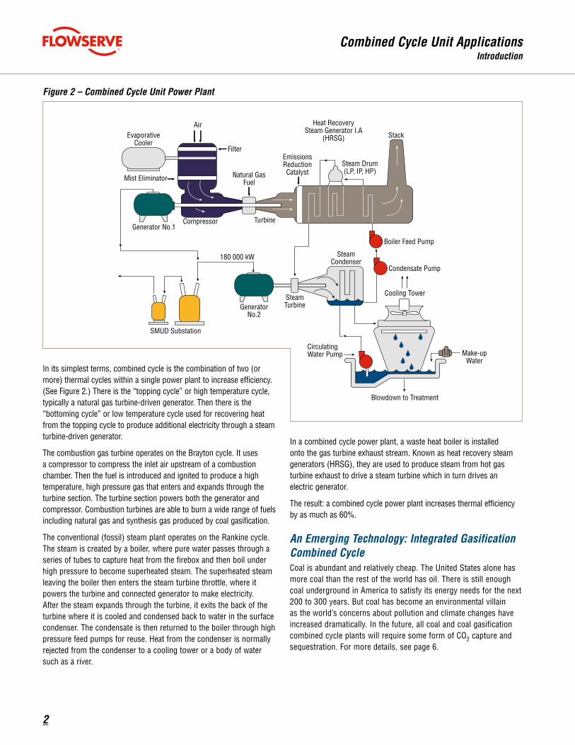
Figure 2 – Combined Cycle Unit Power Plant
In its simplest terms, combined cycle is the combination of two (or more) thermal cycles within a single power plant to increase efficiency. (See Figure 2.) There is the “topping cycle” or high temperature cycle, typically a natural gas turbine-driven generator. Then there is the “bottoming cycle” or low temperature cycle used for recovering heat from the topping cycle to produce additional electricity through a steam turbine-driven generator.
The combustion gas turbine operates on the Brayton cycle. It uses a compressor to compress the inlet air upstream of a combustion chamber. Then the fuel is introduced and ignited to produce a high temperature, high pressure gas that enters and expands through the turbine section. The turbine section powers both the generator and compressor. Combustion turbines are able to burn a wide range of fuels including natural gas and synthesis gas produced by coal gasification.
The conventional (fossil) steam plant operates on the Rankine cycle. The steam is created by a boiler, where pure water passes through a series of tubes to capture heat from the firebox and then boil under high pressure to become superheated steam. The superheated steam leaving the boiler then enters the steam turbine throttle, where it powers the turbine and connected generator to make electricity. After the steam expands through the turbine, it exits the back of the turbine where it is cooled and condensed back to water in the surface condenser. The condensate is then returned to the boiler through high pressure feed pumps for reuse. Heat from the condenser is normally rejected from the condenser to a cooling tower or a body of water such as a river.
In a combined cycle power plant, a waste heat boiler is installed onto the gas turbine exhaust stream. Known as heat recovery steam generators (HRSG), they are used to produce steam from hot gas turbine exhaust to drive a steam turbine which in turn drives an electric generator.
The result: a combined cycle power plant increases thermal efficiency by as much as 60%.
An Emerging Technology: Integrated Gasification Combined CycleCoal is abundant and relatively cheap. The United States alone has more coal than the rest of the world has oil. There is still enough coal underground in America to satisfy its energy needs for the next 200 to 300 years. But coal has become an environmental villain as the world’s concerns about pollution and climate changes have increased dramatically. In the future, all coal and coal gasification combined cycle plants will require some form of CO2 capture and sequestration. For more details, see page 6.

3
Combined Cycle Unit ApplicationsIntroduction
The continued dominance of coal as the fuel of choice for power generating plants may well depend upon clean coal technology, a new generation of energy processes that sharply reduce air emissions and other pollutants compared to older coal-burning systems. To date, the application of clean coal technology has largely been restricted to pilot plant scale. However, in August 2008 Montana’s Crow Nation and Australian-American Energy Co. announced plans to construct a U.S. $7 billion coal-to-liquid (CTL) fuels plant in southeastern Montana. It is expected to open in 2016.
This CTL project presents an ideal opportunity for coal, utility and petroleum companies to collaborate. Utility companies want to turn coal into electricity, while coal companies seek to expand their market from solely power generation to liquid hydrocarbon conversion and petroleum companies can use the carbon dioxide (CO2) produced for enhanced oil recovery (EOR).
Integral to the CTL fuels process is integrated gasification combined cycle (IGCC), a technology that turns coal into gas – synthesis gas (syngas). (See Figure 3.) In a typical IGCC plant, coal is first gasified to synthesis gas – hydrogen and carbon monoxide (CO). The synthesis gas is scrubbed to remove acid gases and mercury. The syngas is then burned in the combustion turbine, and hot exhaust is captured in a waste heat boiler or HRSG and used to raise steam to drive a second turbine. As in natural gas combined cycle, both turbines produce electricity while significantly increasing thermal efficiency: 58 to 60% for IGCC operation versus 38 to 42% for a direct-fired coal unit.
While the IGCC gas plant is far more complex than that of the natural gas combined cycle unit, both the power generating sections and pumping equipment are virtually identical.
Figure 3 – Integrated Gasification Combined Cycle Power Plant
Diluent Nitrogen5300 TPD
Saturator H2O + CO2 to Acid Plant
COS H2Shydrolysis
AcidGasRemoval
Steam55 psig
Generator190 MW
Heat Recovery Steam Generator
Cooling Water
Filter
Air
Slag and Water
RawSyngas
gasifier
RadiantSyngasCooler
Clean Syngas
ColdBox
AirDryer
Coal 2500 TPD
Rod Mill
LockhopperPumpSlurry
Water andRecycle Fines
ProductCompressors
20 MW
Main AirCompressor
30 MW
Oxygen2100 TPD
Water Scrubber
Flyash and WaterConvective
Syngas CoolerSaturated Steam 1600 psig
Economized Boiler Feedwater
Pump
CleanStackGas Combustion
Turbine
Turbine
SteamTurbine
Generator120 MW
Cooling WaterCondenser
Condensate Pump
Compressor

4
Combined Cycle Unit ApplicationsPump Recommendations
Flowserve has achieved a reputation for supplying high quality, dependable pumping equipment to the electric power generation industry and has gained a wealth of experience through handling many of the critical services found in central power generating units. Most of the critical applications in combined cycle units involve water handling – namely, boiler feedwater services, condensate services and water circulating services.
Boiler Feedwater ServicesThe boiler feedwater pumps must handle high pressures and fairly high flow rates and for these services between bearing multistage pumps are commonly used. For very high pressure, double case pumps are sometimes required; Flowserve models DMX and WXH are commonly used. These between bearings, multistage pumps offer the following features and benefits:
Pump Recommendations
Regardless of the size of a combined cycle unit, the water handling pumps are critical elements in the performance of the unit. To give a sense of the types of pumps typically used and the configuration of these pumps, presented below is the water handling pumps for 500 MW combined cycle unit. This is a two-turbine unit and Figure 4 is a schematic of this unit and showing the placement of the pumps.
•HRSG Feedwater Pumps – Total dynamic head (TDH) @ rated capacity – 5800 ft (1770 m) – Capacity @ rated TDH – 950 gpm (215 m3/h) – Temperature – 300ºF (150ºC) – Pump model – WXH (4x12LC, 9 stage) – Materials of construction – Suction and discharge casing are ASTM A216 Grade WCB; impellers are ASTM A743, Grade CA-6NM
Mechanical seal – Flowserve Type QB (Material Code – 5N4A; API Code – BSTFM)
•Auxiliary Steam Boiler Feedwater Pumps – (These pumps are not shown in Figure 4. These are used as start-up pumps or as fill pumps for the system and their location will depend on the individual system design.) Total dynamic head (TDH) @ rated capacity – 760 ft (230 m)
– Capacity @ rated TDH – 550 gpm (125 m3/h) – Temperature – 105ºC (220ºF) – Pump model – HPX (3x6x15M) – Material of construction – Case: Carbon steel; impeller: ASTM A743, Grade CA-6NM
– Mechanical seal – Flowserve Type QB (Material Code – 5N4A; API Code – BSTFM)
Figure 4 – Two-Turbine Combined Cycle Unit Pump Applications
Feature BenefitChoice of axially or radically split case Ease of maintenance
Choice of volute or diffuser case construction
Fluid dynamics best suited for application
Double-suction first-stage impeller (option) Minimizes NPSHR
Flanged balance drum or hydraulically balanced rotating unit
Balances hydraulic thrust and reduces vibration
Finned bearing housing Maximizes heat dissipation

5
Combined Cycle Unit ApplicationsPump Recommendations
Ancillary ServicesDepending on the combined cycle unit design, there can be applications for other types of Flowserve pumps. These include:•Service water•Chlorine booster •Evaporator coil feed• Filter backwash•Gland water circulation•Auxiliary cooling water
•Glycol solution recirculation•Evaporator feed•Service water jockey•Glycol heater drain•Turbine oil transfer•Chemical feed
An integrated gasification combined cycle unit (IGCC) will include a coal handling system and there will probably be a need for the following pumps:
•Dust suppression spray•Dump building sump•Coal pile runoff pond •Treatment pond discharge• Floor drain sump
Guidelines for Mechanical SealsWater, particularly hot water, is difficult to seal. As the temperature increases, the viscosity, and therefore the lubricity, of water drops dramatically. For this reason, proper seal design and materials of construction are critical to providing long and dependable life. Wavy-face seal technology may provide the best solution in these critical services. To ensure proper seal selection for the critical water handling pumps in a combined cycle unit, the advice of a Flowserve FSD sealing specialist should be sought.
Condensate ServicesCondensate services typically have very low values for NPSH available and vertically suspended double case pumps are used. For condensate water services, Flowserve model APKD and VPC pumps are commonly used. These vertically suspended pumps offer the following features and benefits for these difficult services:
Feature Benefit
Standard large eye first-stage impeller Very low NPSH required
Integral wear rings Lower initial cost
Registered motor fitBetter alignment, reduced vibration
Four piece rigid adjustable couplingSuperior alignment, eases
seal replacement
•Condensate Pumps – Total dynamic head (TDH) @ rated capacity – 575 ft (175 m) – Capacity @ rated TDH – 1475 gpm (335 m3/h) – Temperature – 100ºF (38ºC) – Pump model – APKD – Material of construction – Case and impeller (Cast iron) – Mechanical seal – Flowserve Type QB (Material Code – 5N4A, API Code – BSTFM)
Circulating Water ServicesCirculating water services characteristically have very high flow rates at low pressures and vertically suspended mixed flow and axial flow pumps are used. Typical models include the PMR, APH, APMA and HXH. Features and benefits of these pumps include:
Feature Benefit
Open and semi-open impellers Optimum hydraulic coverage
Integral bearing retainer Positive alignment, reduced maintenance
Engineered to customer specifications Maximize efficiency
Split-ring, keyed impeller Reliable, safe operation
•Circulating Water Pumps – Total dynamic head (TDH) @ rated capacity – 80 ft (24 m) – Capacity @ rated TDH – 55 300 gpm (12 560 m3/h) – Temperature – 80ºF (27ºC) – Pump model – 48 HXH (1 stage) – Material of construction – Case (Cast iron), impeller (316L SS)
•Air-to-air Heat Exchangers – In arid regions the use of fresh water for cooling purposes is being reduced. About one in six plants now uses these types of cooling systems, which require no pumps. They also require sig-nificantly more land to construct which is an additional cost.

6
Figure 6 shows a post-combustion capture unit on a chemical plant in Malaysia and Figure 7 shows the carbon capture unit of a coal gasification power plant.
In addition to the process unit itself, site utilities such as cooling water and power supply will also have to be upgraded. With the emphasis of reducing potable water, power plant designers are focusing on air-to-air heat exchangers which will reduce water systems but increase land needs.
CO2 capture is still a developing technology and the key issue is the cost. There are very few commercial units operating and most projects are government-sponsored pilot programs. However, once global laws regulating CO2 emissions are in place, probably in the next two to five years, CO2 capture will become a large market.
Interest in CO2 Capture and Sequestering (CCS) has increased lately as the world begins to struggle with the problems of greenhouse gases and their potential impact on global warming. The Intergovernmental Panel on Carbon Capture (IPCC) estimates that the global emissions of CO2 from fossil fuels in 2000 were 23.5 billion tons. By 2020 this may grow to 44 billion. In order to stabilize CO2 concentration in the atmosphere and reduce the increasing impact CO2 emissions have on raising temperatures, hundreds of billions of tons of CO2 will need to be captured and permanently stored [1].
CO2 CaptureThe key to CCS is the capture of CO2 from point sources. Power plants are the current focus due to their high emission rates of the gas: about 11 billion tons per year at a rate of one ton per megawatt-hour of generation capacity. Other point sources include cement mills, with an emission of about 900 million tons per year, and refineries, which emit approximately 700 million tons per year [1].
Three primary capture technologies are being investigated:
•Post-combustion where the CO2 is removed from the flue gas.• Pre-combustion where the fuel is modified to remove the CO2 before
combustion. Coal to gas technology uses this type of capture.•Oxyfuel combustion where pure oxygen is used instead of air in the
combustion process to produce a flue gas that is 80% CO2. The flue gas can be compressed and stored without additional processing.
Capture of CO2 from flue gas will require a significant investment for power plants and other emission sources. Like the SOx recovery projects of the late 1990s, new process units will need to be installed to remove the CO2 from the flue gas. Figure 5 shows a schematic of a CO2 typical recovery unit. This type of unit can be used in both post and pre-combustion processes.
Combined Cycle Unit ApplicationsCO2 Capture and Sequestration
Figure 6 – A Post-Combustion CO2 Capture Unit Source: [1]
Pretreatment
Flue gasFlue gasDust
RemovalSO2
Removal
CO2
NOXRemoval
Flue Gas to Stack
Steam
Cooling Water
Cross-Exchange,
Surge, Filter,Cooling
To Compressiorand Drying
Reclaimer
CO2
Flue gas
Figure 5 – CO2 Recovery Unit Source: [2]
CO2 Capture and Sequestration
Figure 7 – A Carbon Capture Unit in a Coal-Fired Power Plant (circled area) Source: [1]

7
Combined Cycle Unit ApplicationsCO2 Capture and Sequestration
Figure 8 – Overview of Geologic Storage Options Source: [1]
CO2 TransportationOnce the CO2 is captured at the emission source it must be transported to the storage site. The most economical method for transportation is through pipelines, although liquefying the gas and transporting by ship and rail are being studied. In pipeline operations the gas is compressed to high pressures, greater than 1500 psi (100 bar) where it behaves more like a liquid than a gas (i.e., the dense phase). Once in the dense phase, pumps can then be used to move it through the pipeline. Pipeline transportation is proven technology and currently there are over 1500 miles (2500 km) of CO2 pipelines in the United States.
SequesteringThe goal of sequestering is to permanently store CO2 and prevent its escape to the atmosphere. Several sequestering options have been proposed, including injecting it into deep oceans, or converting it to carbonate minerals, but the leading solution is geologic storage. Figure 8 from IPCC’s 2005 report shows the various geologic storage options.
Geologic storage is favored since the technology is already present. Additionally, the geologic storage options of injecting the CO2 into active oil and gas reservoirs in order to increase production actually produce a market for waste gas. While the technology to inject CO2 into the ground is proven, government agencies around the world are conducting research to determine whether the geologic storage is a permanent solution for CO2 sequestering.
References1. Metz, B., O. Davidson, et al. eds. 2005. Carbon Dioxide Capture
and Storage. New York City. Cambridge University Press.
2. Friedman, B., R. Wissbaum, and S. Anderson, Various Recovery Process Supply CO2 for EOR Projects, Oil & Gas Journal (23 August, 2004).
1. Depleted oil and gas reservoirs2. Use of CO2 in enhanced oil and gas recovery3. Deep saline formations – (a) offshore (b) onshore4. Use of CO2 in enhanced coal bed methane recovery
1
3b
3a2
4
1km
2km
Produced Oil or Gas
Injected CO2
CO2
Gas or Oil

8
Combined Cycle Unit ApplicationsNotes
Notes

9
Combined Cycle Unit ApplicationsNotes
Notes

To find your local Flowserve representative:
For more information about Flowserve Corporation,visit www.flowserve.com or call USA 1 800 728 PUMP (7867)
USA and CanadaFlowserve Corporation5215 North O’Connor Blvd. Suite 2300Irving, Texas 75039-5421 USATelephone: 1 937 890 5839
Europe, Middle East, Africa Flowserve CorporationGebouw HagepointWestbroek 39-514822 ZX Breda NetherlandsTelephone: 31 76 502 8920
Latin America Flowserve CorporationBoulevard del Cafetal Edificio Ninina, Local 7 El Cafetal - Caracas Venezuela 1061 Telephone: 58 212 985 3092 Telefax: 58 212 985 1007
Asia Pacific Flowserve Pte. Ltd.200 Pandan Loop #06-03/04Pantech 21Singapore 128388Telephone: 65 6771 0600Telefax: 65 6779 4607
Bulletin FPD-1308† (E) Printed in USA. April 2009. © Flowserve Corporation
flowserve.com