canalplast.itcanalplast.it/2018_catalogo_estero_web.pdf2018-03-012 catalogue 2018 trunking...
TRANSCRIPT
your solutions to manage energy
vos solutions pour la gestion de l’énergie
18

2 CATALOGUE 2018
TrunkingspecialisTsWho We arecanalplasT is, since more than 35 years, a specialized company in the production and development of trunking systems for electrical installation. Our effort, the technology of our production and the quality of our products bring our presence in the national markets and make us grow more and more towards the international ones, placing us among the leaders of the sector, with a network of agencies and own promoters that constantly cooperate with the clients and their design dept., and having as partners the distributors of electric material with which we collaborate for the”satisfaction of the end client”.
a strategic structurecanalplasT’s facilities cover an area of more than 20.000 m2. Using constantly updated technologies, canalplasT produces profiles made of high quality materials. These products follow a rigid quality control procedure, from production to packing and storing. canalplasT’s facilities house the Research and Development department, as well as administrative and production departments. Approximately 1500 stock items are stored in our 7.500 m2 warehouse. A Customer Care department is in charge of coordinating all orders,from placement to final shipment to the customer.
SpécialiSte en injection extruSion plaStiqueQui sommes-nous?canalplaSt est une société spécialisée depuis plus de 35 ans dans la production et le développement de systèmes de conduits pour installations électriques. L’engagement, la technologie de production, la qualité-produit l’ont amenée à être présent sur les marchés nationaux et internationaux, positionnées parmi les leaders de son secteur. Son réseau d’agents (agences commerciales), ses promoteurs qui intéragissent constamment avec les clients et la conception des produits permettent à nos partenaires distributeurs de donner entière satisfaction aux clients finaux.
une infrastructure stratégiQueAvec une superficie totale de plus de 20.000 m2, dont plus de la moitié entièrement couvert, canalplaSt possède un outil industriel de haute technologie avancée, ce qui leur permet de garantir une grande qualité de fabrication testée, vérifiée, emballée et palettisée. L’usine regroupe les bureaux commerciaux et administratifs, le laboratoire de tests qualité et de contrôle, l’atelier de développement pour la réalisation et l’entretien des moules, l’implantation des machines de production ainsi que le stockage des matières premières. Environs 1500 références sont stockées dans un peu plus de 7500 m². La gestion du stock est entièrement gérée par nos bureaux de coordinations spécialement dédiés aux expéditions et aux enlèvements des marchandises.
3CATALOGUE 2018
Sect
ion
1
®
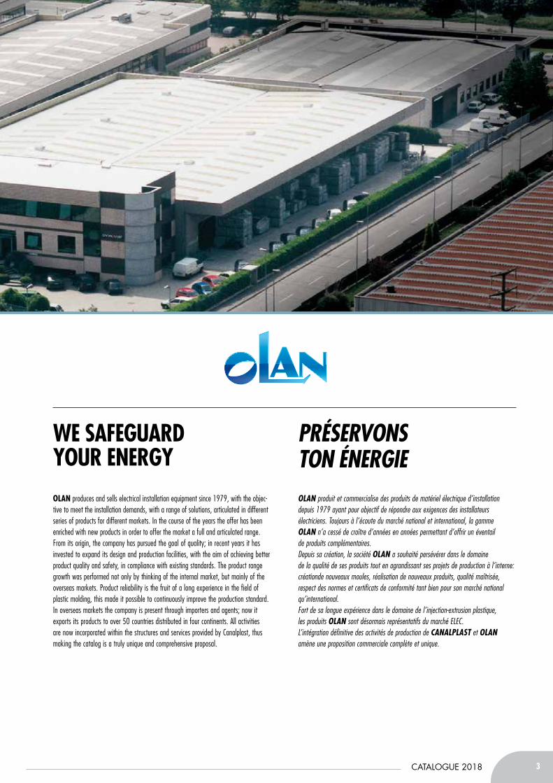
We safeguard your energyolan produces and sells electrical installation equipment since 1979, with the objec-tive to meet the installation demands, with a range of solutions, articulated in different series of products for different markets. In the course of the years the offer has been enriched with new products in order to offer the market a full and articulated range. From its origin, the company has pursued the goal of quality; in recent years it has invested to expand its design and production facilities, with the aim of achieving better product quality and safety, in compliance with existing standards. The product range growth was performed not only by thinking of the internal market, but mainly of the overseas markets. Product reliability is the fruit of a long experience in the field of plastic molding, this made it possible to continuously improve the production standard. In overseas markets the company is present through importers and agents; now it exports its products to over 50 countries distributed in four continents. All activities are now incorporated within the structures and services provided by Canalplast, thus making the catalog is a truly unique and comprehensive proposal.
préServonS ton énergieolan produit et commercialise des produits de matériel électrique d’installation depuis 1979 ayant pour objectif de répondre aux exigences des installateurs électriciens. Toujours à l’écoute du marché national et international, la gamme olan n’a cessé de croître d’années en années permettant d’offrir un éventail de produits complémentaires.Depuis sa création, la société olan a souhaité persévérer dans le domaine de la qualité de ses produits tout en agrandissant ses projets de production à l’interne: créationde nouveaux moules, réalisation de nouveaux produits, qualité maîtrisée, respect des normes et certificats de conformité tant bien pour son marché national qu’international.Fort de sa longue expérience dans le domaine de l’injection-extrusion plastique, les produits olan sont désormais représentatifs du marché ELEC.L’intégration définitive des activités de production de canalplaSt et olan amène une proposition commerciale complète et unique.

4 CATALOGUE 2018
Safety and reSiStance - Sécurité et réSiStance
TesTed valueProduction at canalplasT is constantly supervised and monitored by technical staff from the Quality Control Department, to guarantee full compliance and conformity to the specific legal requirements and to obtain a high quality product with continuous improvements. The company invests resources, incurring in major expenditures, for the researching and testing materials, for equipment, machinery and the development of new products.
la valeur teStéeLa production canalplaSt est systématiquement prise en charge par notre bureau de contrôle qualité afin d’assurer en permanence la fiabilité de nos produits et la mise en adéquation aux nombreuses normes et certifications Italiennes et internationales. La société investit régulièrement dans la recherche et le développement, notamment pour tout ce qui concerne les essais matériaux, moules, machines et projets de nouveaux produits.
Refrigerator to prepare samples for low temperature shock tests.
Chambre froide pour la climatisation à l’impact des éprouvettes à basse température.
Apparatus for finger-removal and side-segment removal test.
Essais d’équipement et sur le coté du segment retrait de la lame.
Cabin for age acceleration test.
Chambre climatique pour le test de vieillissement accélère.
Apparatus for testing side walls and lids lowering.
Équipement pour tester les couvercles inférieurs et les parois latérales.
Apparatus for testing heat resistance (850° C) GWT.
Résistance au fil incandescent 850° C.
Apparatus for shock testing at room temperature.
Équipement de test de choc à température ambiante.
Apparatus for shock testing at low temperature.
Équipement pour tester l’impact à basse température.
Apparatus for testing heat resistance.
Équipement de test résistance à la chaleur.
Apparatus for insulation resistance above 100 MΩ.
Équipement pour tester la résistance d’isolation de plus de 100 MΩ.
Apparatus for flame propagation resistance test.
Équipement pour essais de résistanceà la propagation des flammes.
5CATALOGUE 2018
Sect
ion
1
cerTified qualiTyfor us, quality is not a slogan, but a term that implies strict adherence to creating a product of the highest quality. IMQ, CSA UL and GOST certifications are an evidence of canalplasT‘s quality mission. Since 1991, Canalplast has also received the CSQ, ISO 9001:2008 Certification.
certificationS et normeSla qualité est une priorité pour canalplaSt. Il en résulte de nos homologations telles que IMQ, CSA, UL, GOST. Notre laboratoire est certifié CSQ, ISO 90001 : 2008 depuis Mai 1991.
Safety and reSiStance - Sécurité et réSiStance Safety and reSiStance - Sécurité et réSiStance
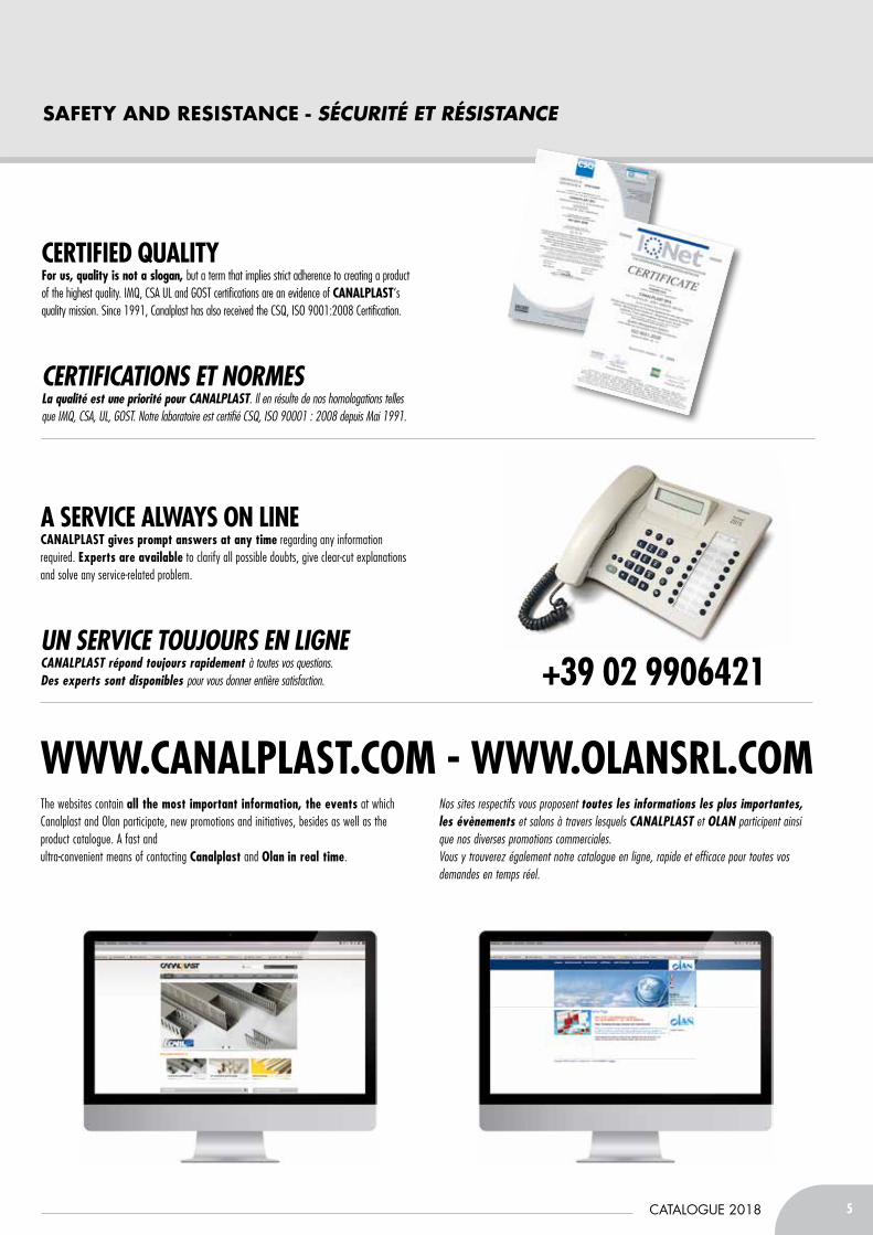
The websites contain all the most important information, the events at which Canalplast and Olan participate, new promotions and initiatives, besides as well as the product catalogue. A fast and ultra-convenient means of contacting canalplast and olan in real time.
Nos sites respectifs vous proposent toutes les informations les plus importantes, les évènements et salons à travers lesquels canalplaSt et olan participent ainsi que nos diverses promotions commerciales.Vous y trouverez également notre catalogue en ligne, rapide et efficace pour toutes vos demandes en temps réel.
+39 02 9906421
WWW.canalplasT.com - WWW.olansrl.com
a service alWays on linecanalplasT gives prompt answers at any time regarding any information required. experts are available to clarify all possible doubts, give clear-cut explanations and solve any service-related problem.
un Service toujourS en lignecanalplaSt répond toujours rapidement à toutes vos questions.Des experts sont disponibles pour vous donner entière satisfaction.

6 CATALOGUE 2018
indeX/Sommaire
Section 1 Section 3
Section 2
inStaLLation trUnKinGSGouLotteS D’inStaLLation
indUStriaL Wire dUctScÂBLaGe inDuStrieL 8
28 52
44air conditioninG inStaLLationGouLotteS De cLimatiSation
Section 4
eLectricaL eQUiPMent inStaLLationmatérieL éLectriQue D’inStaLLation
MINITRUNKINGS AND ACCESSORIESMOULURES Et accESSOiRES 29
TRUNKING SYSTEMS AND ACCESSORIESGOULOttES Et accESSOiRES 31
“SYS45” QUICK INSTALLATION TRUNKINGSGOULOttES pORtE-pRiSES RapiDE “SYS45” 35
DISTRIbUTION bOARD TRUNKINGSGaiNES tEcHNiQUES DE LOGEMENt (GtL) 37
CAvITY fLOOR SOCKET bOxESBOÎtES DE SOL 40
fLOOR SOCKET-pOINT TURRETScOLONNES DE BUREaU 43
GeneraL noteS GENERAL SALES CONDITIONS - SYMbOLS 98
noteS GénéraLeScONDitiONS GéNéRaLES DE vENtE - SYMBOLES 99
WIRING DUCTSGOULOttES DE cÂBLaGE 9
TRUNKINGS fOR LIfTSGOULOttES pOUR aScENSORiStES 12
HALOGEN fREE WIRE DUCTS fOR SWITCHbOARDSGOULOttES SaNS HaLOGENES 13
ACCESSORIES OUtiLS 22
DIN RAILS - ACCESSORIESRaiLS DiN MétaLLiQUE - OUtiLS 25
AIR CONDITIONING DUCTSSYStèME DE GOULOttES pOUR L’aiR cONDitiONNé 45
CONDENSATION DRAIN ACCESSORIESaccESSOiRES DE viDaNGE cONDENSatiON 48
bASES AND bRACKETSBaSES Et SUppORtS 50
fLUSH JUNCTION bOxESBOÎtES D’ENcaStREMENt 53
JUNCTION bOxES fOR WALL MOUNTINGbOîTES DE DéRIvATION 58
fLUSH AND WALL DISTRIbUTION bOARDScOffREtS DE DiStRiBUtiON 72
CIRCUIT bREAKERS AND fUSE HOLDERSDiSjONctEURS, BLOcS DifféRENtiELS Et cOUpE ciRcUit 81
fITTINGS, fASTENINGS, CONNECTORS AND ACCESSORIESMaNcHONS, BaRREttES DE cONNExiONS Et accESSOiRES 89
fISHTApES AND HOSEScORDONS ExtENSiBLES, tiRE fiLS Et OUtiLS 97
7CATALOGUE 2018
Sect
ion
1
indeX neWS/Sommaire deS noUveLLeS
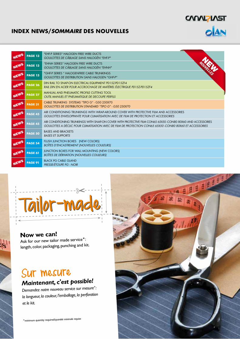
Now we can! Ask for our new tailor made service*:
length, color, packaging, punching and kit.
Sur mesureMaintenant, c'est possible!Demandez notre nouveau service sur mesure*:
la longueur, la couleur, l’emballage, la perforation
et le kit.
*minimum quantity required/quantité minimale requise
Tailor-madeTailor-made✂
NEWS
NEWS
NEWS
NEWS
NEWS
NEWS
NEWS
NEWS
NEWS
NEWS
NEWS
NEWS
PaGe 13"EHf-p SERIES" HALOGEN fREE WIRE DUCTSGOULOttES DE cÂBLaGE SaNS HaLOGèN "EHf-p"
PaGe 13“EHNH SERIES” HALOGEN fREE WIRE DUCTSGOULOttES DE cÂBLaGE SaNS HaLOGèN "EHNH"
PaGe 13"GHf-p SERIES “ HALOGENfREE CAbLE TRUNKINGSGOULOttES DE DiStRiBUtiON SaNS HaLOGEN "GHf-p"
PaGe 26DIN RAIL TO SNAp-ON ELECTRICAL EQUIpMENT pD15Z-pD15Zf4RaiL DiN EN aciER pOUR accROcHaGE DE MatéRiEL éLEctRiQUE pD15Z-pD15Zf4
PaGe 27MANUAL AND pNEUMATIC pROfILE CUTTING TOOLOUtiL MaNUEL Et pNEUMatiQUE DE DEcOUpE pERfiLS
PaGe 31CAbLE TRUNKING SYSTEMS “TIpO G” - G50 250x70GOULOttES DE DiStRiBUtiON StaNDaRD “tipO G” - G50 250x70
PaGe 45AIR CONDITIONING TRUNKINGS WITH WRAp-AROUND COvER WITH pROTECTIvE fILM AND ACCESSORIESGOULOttES ENvELOppaNtE pOUR cLiMatiSatiON avEc DE fiLM DE pROtEctiON Et accESSORiES
PaGe 45AIR CONDITIONING TRUNKINGS WITH SNAp-ON COvER WITH pROTECTIvE fILM CON65 65x50 -CON80 80x60 AND ACCESSORIESGOULOttES a DécLic pOUR cLiMatiSatiON avEc DE fiLM DE pROtEctiON cON65 65x50 -cON80 80x60 Et accESSORiES
PaGe 50bASES AND bRACKETSBaSES Et SUppORtS
PaGe 54fLUSH JUNCTION bOxES (NEW COLORS)BOÎtES D’ENcaStREMENt (NOUvELLES cOULEURS)
PaGe 61JUNCTION bOxES fOR WALL MOUNTING (NEW COLORS)BOÎtES DE DéRivatiON (NOUvELLES cOULEURS)
PaGe 91bLACK pG CAbLE GLANDpRESSE-étOUpE pG - NOiR

INDUSTRIAL WIRE DUCTS➤ WIRING DUCTS➤ TRUNKINGS fOR LIfTS➤ HALOGEN fREE WIRE DUCTS fOR SWITCHbOARDS➤ ACCESSORIES➤ DIN RAILS
Section 1
CÂBLAGE INDUSTRIEL➤ GOULOttES DE cÂBLaGE➤ GOULOttES pOUR aScENSORiStES➤ GOULOttES SaNS HaLOGENES➤ OUtiLS➤ RaiLS DiN MétaLLiQUE
9CATALOGUE 2018
INDUSTRIAL WIRE DUCTS/CÂBLAGE INDUSTRIEL
SECT
IoN
1
SECTIoN 1
WIRING DUCTS/GOULOttES DE cÂBLaGE
CODERÉFÉRENCE
bOttOm SECtiOnsECtioN du FoNd
b mm
H mm
PACK mEMB. m
PACK m3
EMB. m3
PACK KgEMB. Kg
PAllEt mPALEttE m
tECHniCAl DAtAdoNNÉEs tECh.
FiG. C D P
E16
25
30 80 0,057 16,0 1600 1 8 12 20
E13 40 60 0,051 15,8 1500 1 8 12 20
E7 60 40 0,051 15,0 1000 1 8 12 20
E14 80 32 0,057 15,6 640 2 8 12 20
E34 100 24 0,057 13,8 480 2 8 12 20
E23
40
30 48 0,051 13,5 1200 1 8 12 20
E8 40 40 0,057 14,2 800 1 8 12 20
E5 60 36 0,069 17,8 720 1 8 12 20
E15 80 24 0,057 14,7 480 2 8 12 20
E35 100 16 0,051 14,1 400 2 8 12 20
E24
60
30 32 0,051 14,4 800 1 8 12 20
E4 40 24 0,051 11,4 600 1 8 12 20
E9 60 24 0,069 15,5 480 1 8 12 20
E11 80 24 0,081 18,5 360 2 8 12 20
E18 100 16 0,074 16,9 320 2 8 12 20
E26
80
40 24 0,069 14,3 480 1 8 12 20
E6 60 24 0,092 19,2 288 1 8 12 20
E12 80 24 0,110 21,7 288 2 8 12 20
E36 100 16 0,093 19,8 192 2 8 12 20
E27
100
40 16 0,057 12,3 320 1 8 12 20
E17 60 20 0,092 18,7 240 1 8 12 20
E19 80 16 0,092 18,1 192 1 8 12 20
E37 100 16 0,114 21,5 192 2 8 12 20
E43 150 8 0,085 14,6 120 3 8 12 20
E28
120
40 20 0,081 18,2 300 1 8 12 20
E10 60 16 0,085 17,5 240 1 8 12 20
E32 80 16 0,106 20,5 192 2 8 12 20
E38 100 8 0,071 12,6 120 2 8 12 20
E30150
60 12 0,081 17,3 180 1 8 12 20
E33 80 12 0,106 18,9 144 2 8 12 20
E39 100 8 0,081 15,1 120 2 8 12 20
E31200
60 8 0,071 14,6 120 1 8 12 20
E48 80 8 0,092 16,6 96 2 8 12 20
E40 100 8 0,114 18,2 96 2 8 12 20
WiRE DUCtS WitH bOttOm RAilS - SUPPLIED UPON REQUEST AND FOR QUANTITIES TO BE AGREEDGOULOTTES avEc GUidE inTEGréE aU fOnd - DISPONIBLE SUR DEMANDE ET POUR DES QUANTITES A CONVENIR
E5 CG40
60 36 0,069 17,8 720 1 8 12 20
E15 CG 80 24 0,057 14,7 480 2 8 12 20
E4 CG60
40 24 0,051 11,4 600 1 8 12 20
E9 CG 60 24 0,069 15,5 480 1 8 12 20
E11 CG 80 24 0,081 18,5 360 2 8 12 20
E26 CG80
40 24 0,069 14,3 480 1 8 12 20
E6 CG 60 24 0,092 19,2 288 1 8 12 20
E12 CG 80 24 0,11 21,7 288 2 8 12 20
E17 CG100
60 20 0,092 18,7 240 1 8 12 20
E19 CG 80 16 0,092 18,1 192 1 8 12 20
Colour: Grey RAL 7030/ Couleur: Gris RAL 7030
CODERÉFÉRENCE
b mm
GCOP25 25
GCOP40 40
GCOP60 60
GCOP80 80
GCOP100 100
GCOP120 120
GCOP150 150
GCOP200 200
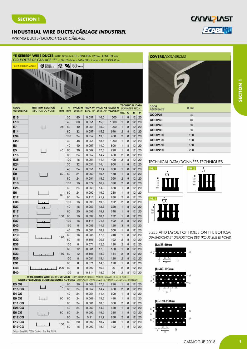
coverS/COUVERCLEs“e SerieS” Wire dUctS WITH 8mm SLOTS - FINGERS 12mm - LENGTH 2m.GOULOTTEs DE CÂBLAGE “E” - fentes 8mm - LAMeLLes 12mm - Longueur 2m
RoHS cOmpLIaNcE A Norme EN50085-2-3
®
TECHNICAL DATA/DONNéES TECHNIQUES
c dp
H304060
mm
fig. 1
H80
100mm
c dpfig. 2
fig. 3c d
H150mm
p
SIZES AND LAYOUT Of HOLES ON THE bOTTOMDiMENSiONS Et DiSpOSitiON DES tROUS SUR LE fOND
(B)=80-120mm
4,5
4,5
8 50
25 25 25 25
25
25
(B)=150-200mm
25
50
4,5
4,5
25 25
50148
25
(a)=25-60mm
4,5
8
25 25
5014
6,5
10
INDUSTRIAL WIRE DUCTS/CÂBLAGE INDUSTRIEL
CATALOGUE 2018
SECTIoN 1
WIRING DUCTS/GOULOttES DE cÂBLaGE
CODERÉFÉRENCE
bOttOm SECtiOnsECtioN du FoNd
b mm
H mm
PACK mEMB. m
PACK m3
EMB. m3
PACK KgEMB. Kg
PAllEt mPALEttE m
tECHniCAl DAtAdoNNÉEs tECh.
FiG. C D P
E2015
17 120 0,036 11,3 3600 1 4 6 10
E22 30 96 0,042 14,1 - - 1 4 6 10
E25 40 72 0,042 14,8 2160 1 4 6 10
E164
25
30 80 0,057 16 1600 1 4 6 10
E134 40 60 0,051 15,8 1500 1 4 6 10
E74 60 40 0,051 15 1000 1 4 6 10
E144 80 32 0,057 15,6 640 2 4 6 10
E344 100 24 0,057 13,8 480 1 4 6 10
E84
40
40 40 0,057 14,2 800 1 4 6 10
E54 60 36 0,069 17,8 720 1 4 6 10
E154 80 24 0,057 14,7 480 2 4 6 10
E354 100 16 0,051 14,1 400 1 4 6 10
E44
60
40 24 0,051 11,4 600 1 4 6 10
E94 60 24 0,069 15,5 480 1 4 6 10
E114 80 24 0,081 18,5 360 2 4 6 10
E184 100 16 0,074 16,9 320 1 4 6 10
E264
80
40 24 0,069 14,3 480 1 4 6 10
E64 60 24 0,092 19,2 288 1 4 6 10
E124 80 24 0,11 21,7 288 2 4 6 10
E364 100 16 0,093 19,8 192 1 4 6 10
E174100
60 20 0,092 18,7 240 1 4 6 10
E194 80 16 0,092 18,1 192 2 4 6 10
E374 100 16 0,114 21,5 192 1 4 6 10
E104120
60 16 0,085 17,5 240 1 4 6 10
E324 80 16 0,106 20,5 192 2 4 6 10
E384 100 8 0,071 12,6 120 1 4 6 10
WiRE DUCtS WitH bOttOm RAilS - SUPPLIED UPON REQUEST AND FOR QUANTITIES TO BE AGREEDGOULOTTES avEc GUidE inTEGréE aU fOnd - DISPONIBLE SUR DEMANDE ET POUR DES QUANTITES A CONVENIR
E54 CG40
60 36 0,069 17,8 720 1 4 6 10
E154 CG 80 24 0,057 14,7 480 2 4 6 10
E44 CG60
40 24 0,051 11,4 600 1 4 6 10
E94 CG 60 24 0,069 15,5 480 1 4 6 10
E114 CG 80 24 0,081 18,5 360 2 4 6 10
E264 CG80
40 24 0,069 14,3 480 1 4 6 10
E64 CG 60 24 0,092 19,2 288 1 4 6 10
E124 CG 80 24 0,11 21,7 288 2 4 6 10
E174 CG100
60 20 0,092 18,7 240 1 4 6 10
E194 CG 80 16 0,092 18,1 192 2 4 6 10
Colour: Grey RAL 7030/ Couleur: Gris RAL 7030
CODERÉFÉRENCE
b mm
GCOP15 15
GCOP25 25
GCOP40 40
GCOP60 60
GCOP80 80
GCOP100 100
GCOP120 120
GCOP150 150
GCOP200 200
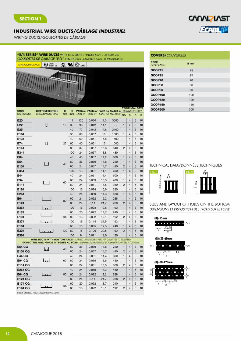
coverS/COUVERCLEs
®
H80
mm
c dp
TECHNICAL DATA/DONNéES TECHNIQUES
fig. 1 fig. 2
c dpH
17304060
100mm
SIZES AND LAYOUT Of HOLES ON THE bOTTOMDiMENSiONS Et DiSpOSitiON DES tROUS SUR LE fOND
(B)=15mm4,5
8
25 25
50
(B)=80-120mm
4,5
4,5
8 50
25 25 25 25
25
25
(B)=25-60mm
4,5
8
25 25
5014
6,5
“e/4 SerieS” Wire dUctS WITH 4mm SLOTS - FINGER 6mm - LENGTH 2mGOULOTTEs DE CÂBLAGE “E/4”- fentes 4mm - LAMeLLes 6mm - Longueur 2m
RoHS cOmpLIaNcE A Norme EN50085-2-3
11CATALOGUE 2018
INDUSTRIAL WIRE DUCTS/CÂBLAGE INDUSTRIEL
SECT
IoN
1
SECTIoN 1
WIRING DUCTS/GOULOttES DE cÂBLaGE
CODERÉFÉRENCE
bOttOm SECtiOnsECtioN du FoNd
bmm
Hmm
PACK mEMB. m
PACK m3
EMB. m3
PACK KgEMB. Kg
PAllEt mPALEttE m
tECHniCAl DAtAdoNNÉEs tECh.
FiG. C D P
ED2525
25
25 84 0,051 16,5 2100 1 5 7,5 12,5
ED2537 37,5 64 0,057 15,1 1280 1 5 7,5 12,5
ED2550 50 52 0,057 15,3 1040 1 5 7,5 12,5
ED2575 75 32 0,051 13,1 800 2 5 7,5 12,5
ED373737,5
37,5 48 0,057 14,4 960 1 5 7,5 12,5
ED3750 50 32 0,051 11,2 800 1 5 7,5 12,5
ED3775 75 32 0,069 15 640 2 5 7,5 12,5
ED505050
50 24 0,051 10,8 600 1 5 7,5 12,5
ED5075 75 24 0,069 13,4 480 2 5 7,5 12,5
ED755075
50 24 0,069 13,7 480 1 5 7,5 12,5
ED7575 75 16 0,069 11,8 320 2 5 7,5 12,5
ED10050100
50 16 0,064 12,2 288 1 5 7,5 12,5
ED10075 75 16 0,085 14,1 240 2 5 7,5 12,5
ED12575 125 75 12 0,085 13,6 180 2 5 7,5 12,5
Colour: Grey RAL 7030/ Couleur: Gris RAL 7030
CODERÉFÉRENCE
b mm H mmPACK mEMB. m
PACK m3
EMB. m3
PACK KgEMB. Kg
ED110K40 90 90 8 0,036 12,5
ED110K60 110 110 8 0,036 13,1
Colour: Grey RAL 7030/ Couleur: Gris RAL 7030
coverS/COUVERCLEs
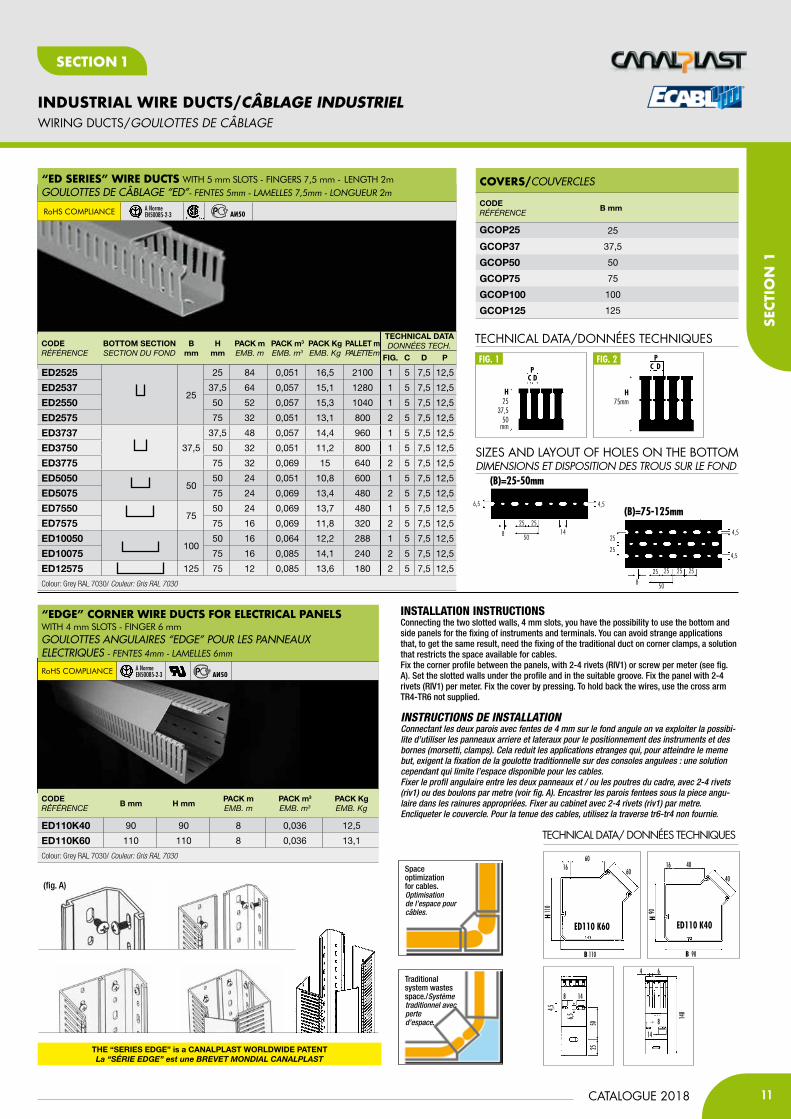
INSTALLATION INSTRUCTIONSConnecting the two slotted walls, 4 mm slots, you have the possibility to use the bottom and side panels for the fixing of instruments and terminals. You can avoid strange applications that, to get the same result, need the fixing of the traditional duct on corner clamps, a solution that restricts the space available for cables.Fix the corner profile between the panels, with 2-4 rivets (RIV1) or screw per meter (see fig. A). Set the slotted walls under the profile and in the suitable groove. Fix the panel with 2-4 rivets (RIV1) per meter. Fix the cover by pressing. To hold back the wires, use the cross arm TR4-TR6 not supplied.
InstructIons de InstallatIon Connectant les deux parois avec fentes de 4 mm sur le fond angule on va exploiter la possibi-lite d’utiliser les panneaux arriere et lateraux pour le positionnement des instruments et des bornes (morsetti, clamps). Cela reduit les applications etranges qui, pour atteindre le meme but, exigent la fixation de la goulotte traditionnelle sur des consoles angulees : une solution cependant qui limite l’espace disponible pour les cables. Fixer le profil angulaire entre les deux panneaux et / ou les poutres du cadre, avec 2-4 rivets (riv1) ou des boulons par metre (voir fig. A). Encastrer les parois fentees sous la piece angu-laire dans les rainures appropriées. Fixer au cabinet avec 2-4 rivets (riv1) par metre. Encliqueter le couvercle. Pour la tenue des cables, utilisez la traverse tr6-tr4 non fournie.
Traditional system wastes space./Système traditionnel avec perte d’espace.
Space optimizationfor cables.Optimisation de l’espace pour câbles.
®
“ed SerieS” Wire dUctS WITH 5 mm SLOTS - FINGERS 7,5 mm - LENGTH 2mGOULOTTEs DE CÂBLAGE “ED”- fentes 5mm - LAMeLLes 7,5mm - Longueur 2m
RoHS cOmpLIaNcE A Norme EN50085-2-3
“edGe” corner Wire dUctS for eLectricaL PaneLS WITH 4 mm SLOTS - FINGER 6 mmGOULOTTEs ANGULAIREs “EDGE” POUR LEs PANNEAUX ELECTRIQUEs - fentes 4mm - LAMeLLes 6mm
RoHS cOmpLIaNcE A Norme EN50085-2-3
CODERÉFÉRENCE
b mm
GCOP25 25
GCOP37 37,5
GCOP50 50
GCOP75 75
GCOP100 100
GCOP125 125
TECHNICAL DATA/DONNéES TECHNIQUES
fig. 1 fig. 2
c dp
H25
37,550
mm
H75mm
c dp
SIZES AND LAYOUT Of HOLES ON THE bOTTOMDiMENSiONS Et DiSpOSitiON DES tROUS SUR LE fOND
(B)=75-125mm
4,5
4,5
8 50
25 25 25 25
25
25
(B)=25-50mm
4,5
8
25 25
5014
6,5
tHE “SERiES EDGE” is a CAnAlPlASt WORlDWiDE PAtEntLa “SériE EdGE” est une BrEvET MOndiaL canaLPLaST
(fig. A)
TECHNICAL DATA/ DONNéES TECHNIQUES
5025
14
4,5
6,5
8
140
14
8
4 6
60
110
110
6016
ed110 k60
H
B
40
90
90
16 40
ed110 k40
B
H
12
INDUSTRIAL WIRE DUCTS/CÂBLAGE INDUSTRIEL
CATALOGUE 2018
SECTIoN 1
TRUNKINGS fOR LIfTS/GOULOttES pOUR aScENSORiStES
CODERÉFÉRENCE
bOttOm SECtiOnsECtioN du FoNd
b mm H mmPACK mEMB. m
PACK m3
EMB. m3
PACK KgEMB. Kg
S. G. mm2
AS G8 40 40 40 0,057 16 1310
AS G460
40 24 0,051 13 1960
AS G9 60 24 0,069 18 3080
AS G2680
40 24 0,069 15,8 2665
AS G6 60 24 0,092 22 4175
AS G17100
60 20 0,092 21 5295
AS G19 80 16 0,092 21,2 7215
AS G10120
60 16 0,085 19,3 6390
AS G32 80 16 0,106 23,1 8710
AS G33 150 80 12 0,106 21,2 10770
CODERÉFÉRENCE
bOttOm SECtiOnsECtioN du FoNd
b mm H mmPACK mEMB. m
PACK m3
EMB. m3
PACK KgEMB. Kg
S. G. mm2
AS G8P 40 40 40 0,057 16 1310
AS G4P 60 40 24 0,051 12,9 1960
AS G26P 80 40 24 0,069 15,4 2665
CODERÉFÉRENCE
bOttOm SECtiOnsECtioN du FoNd
b mm H mmPACK mEMB. m
PACK m3
EMB. m3
PACK KgEMB. Kg
S. G. mm2
G055P 50 50 24 0,051 12,7 2126
G075P 75 50 24 0,069 16,3 3115
G105P 100 50 16 0,064 14,6 4270
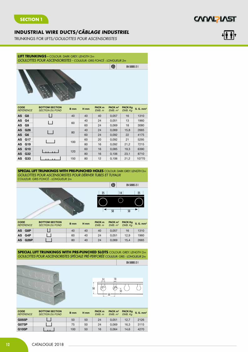
SPeciaL Lift trUnKinGS WitH Pre-PUncHed HoLeS cOLOuR: DaRK GREY. LENGTH 2mGOULOTTEs POUR AsCENsORIsTEs POUR DéRIVER TUBEs ET TUyAUX couLeur: gris foncé - Longueur 2m
EN-50085-2-1
SPeciaL Lift trUnKinGS WitH Pre-PUncHed SLotS cOLOuR: GREY. LENGTH 2mGOULOTTEs POUR AsCENsORIsTEs sPéCIALE PRé-PERFORéE couLeur: gris - Longueur 2m
EN-50085-2-1
Lift trUnKinGS - cOLOuR: DaRK GREY. LENGTH 2mGOULOTTEs POUR AsCENsORIsTEs - couLeur: gris foncé - Longueur 2m
EN-50085-2-1
25 14 25
50 50
13CATALOGUE 2018
INDUSTRIAL WIRE DUCTS/CÂBLAGE INDUSTRIEL
SECT
IoN
1
SECTIoN 1
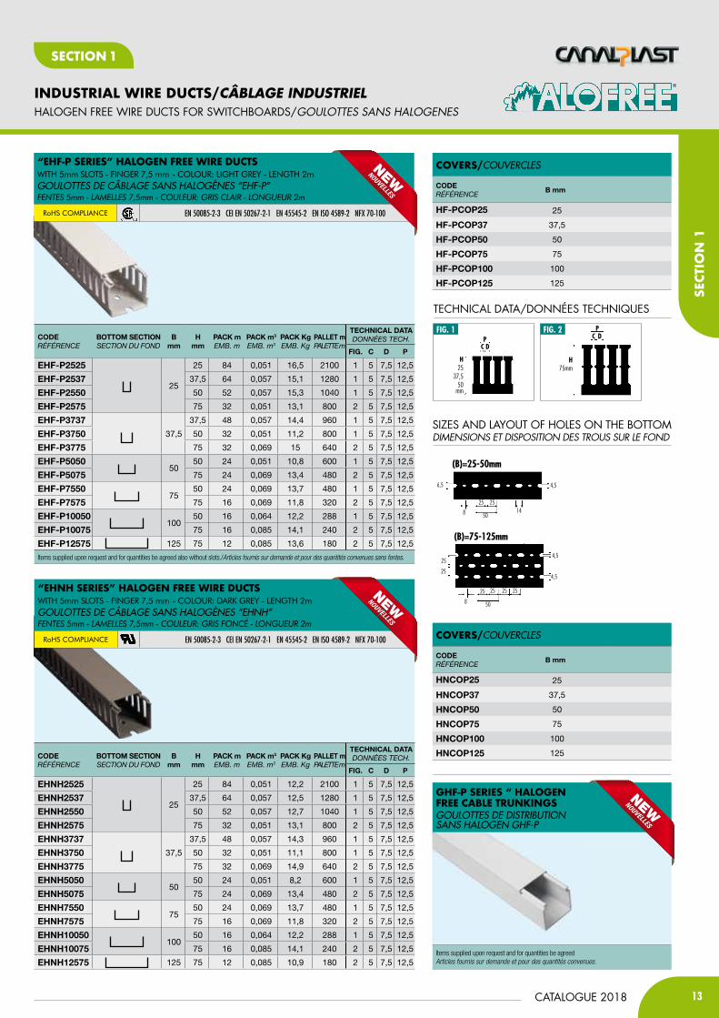
GHf-P SerieS “ HaLoGen free caBLe trUnKinGSGOULOTTEs DE DIsTRIBUTION sANs HALOGEN GHF-P
HALOGEN fREE WIRE DUCTS fOR SWITCHbOARDS/GOULOttES SaNS HaLOGENES
CODERÉFÉRENCE
bOttOm SECtiOnsECtioN du FoNd
b mm
H mm
PACK mEMB. m
PACK m3
EMB. m3
PACK KgEMB. Kg
PAllEt mPALEttE m
tECHniCAl DAtAdoNNÉEs tECh.
FiG. C D P
EHF-P2525
25
25 84 0,051 16,5 2100 1 5 7,5 12,5
EHF-P2537 37,5 64 0,057 15,1 1280 1 5 7,5 12,5
EHF-P2550 50 52 0,057 15,3 1040 1 5 7,5 12,5
EHF-P2575 75 32 0,051 13,1 800 2 5 7,5 12,5
EHF-P373737,5
37,5 48 0,057 14,4 960 1 5 7,5 12,5
EHF-P3750 50 32 0,051 11,2 800 1 5 7,5 12,5
EHF-P3775 75 32 0,069 15 640 2 5 7,5 12,5
EHF-P505050
50 24 0,051 10,8 600 1 5 7,5 12,5
EHF-P5075 75 24 0,069 13,4 480 2 5 7,5 12,5
EHF-P755075
50 24 0,069 13,7 480 1 5 7,5 12,5
EHF-P7575 75 16 0,069 11,8 320 2 5 7,5 12,5
EHF-P10050100
50 16 0,064 12,2 288 1 5 7,5 12,5
EHF-P10075 75 16 0,085 14,1 240 2 5 7,5 12,5
EHF-P12575 125 75 12 0,085 13,6 180 2 5 7,5 12,5
Items supplied upon request and for quantities be agreed also without slots./Articles fournis sur demande et pour des quantités convenues sans fentes.
CODERÉFÉRENCE
bOttOm SECtiOnsECtioN du FoNd
b mm
H mm
PACK mEMB. m
PACK m3
EMB. m3
PACK KgEMB. Kg
PAllEt mPALEttE m
tECHniCAl DAtAdoNNÉEs tECh.
FiG. C D P
EHnH2525
25
25 84 0,051 12,2 2100 1 5 7,5 12,5
EHnH2537 37,5 64 0,057 12,5 1280 1 5 7,5 12,5
EHnH2550 50 52 0,057 12,7 1040 1 5 7,5 12,5
EHnH2575 75 32 0,051 13,1 800 2 5 7,5 12,5
EHnH373737,5
37,5 48 0,057 14,3 960 1 5 7,5 12,5
EHnH3750 50 32 0,051 11,1 800 1 5 7,5 12,5
EHnH3775 75 32 0,069 14,9 640 2 5 7,5 12,5
EHnH505050
50 24 0,051 8,2 600 1 5 7,5 12,5
EHnH5075 75 24 0,069 13,4 480 2 5 7,5 12,5
EHnH755075
50 24 0,069 13,7 480 1 5 7,5 12,5
EHnH7575 75 16 0,069 11,8 320 2 5 7,5 12,5
EHnH10050100
50 16 0,064 12,2 288 1 5 7,5 12,5
EHnH10075 75 16 0,085 14,1 240 2 5 7,5 12,5
EHnH12575 125 75 12 0,085 10,9 180 2 5 7,5 12,5
coverS/COUVERCLEs
®
TECHNICAL DATA/DONNéES TECHNIQUES
fig. 1 fig. 2
c dp
H25
37,550
mm
H75mm
c dp
SIZES AND LAYOUT Of HOLES ON THE bOTTOMDiMENSiONS Et DiSpOSitiON DES tROUS SUR LE fOND
(B)=75-125mm
4,5
4,5
8 50
25 25 25 25
25
25
(B)=25-50mm
4,5
8
25 25
5014
6,5
“eHf-P SerieS” HaLoGen free Wire dUctS WITH 5mm SLOTS - FINGER 7,5 mm - cOLOuR: LIGHT GREY - LENGTH 2mGOULOTTEs DE CÂBLAGE sANs HALOGèNEs “EHF-P”fentes 5mm - LAMeLLes 7,5mm - couLeur: gris cLAir - Longueur 2m
RoHS cOmpLIaNcE EN 50085-2-3 CEI EN 50267-2-1 EN 45545-2 EN ISO 4589-2 NFX 70-100
“eHnH SerieS” HaLoGen free Wire dUctS WITH 5mm SLOTS - FINGER 7,5 mm - cOLOuR: DaRK GREY - LENGTH 2mGOULOTTEs DE CÂBLAGE sANs HALOGèNEs “EHNH”fentes 5mm - LAMeLLes 7,5mm - couLeur: gris foncé - Longueur 2m
RoHS cOmpLIaNcE EN 50085-2-3 CEI EN 50267-2-1 EN 45545-2 EN ISO 4589-2 NFX 70-100
CODERÉFÉRENCE
b mm
HF-PCOP25 25
HF-PCOP37 37,5
HF-PCOP50 50
HF-PCOP75 75
HF-PCOP100 100
HF-PCOP125 125
coverS/COUVERCLEs
CODERÉFÉRENCE
b mm
HnCOP25 25
HnCOP37 37,5
HnCOP50 50
HnCOP75 75
HnCOP100 100
HnCOP125 125
Items supplied upon request and for quantities be agreedArticles fournis sur demande et pour des quantités convenues.

14
INDUSTRIAL WIRE DUCTS/CÂBLAGE INDUSTRIEL
CATALOGUE 2018
SECTIoN 1
Wire fiLL caPacity cHart/TABLEAU DE CAPACITE DE REMPLIssAGE DE FIL
ElEctrical wirEs/fils électriques cOMMUNicatiON
H07V-U/r/K 8 awG 10 awG 12 awG 14 awG 16 awG 18 awG 22 awG 24 awG
trUNKiNG DiMENsiONGOulOtte DiMeNsiON
B x H mm
s.G.mm2
mm2 .216 .153 .122 .158 .105 .139 .165 .096 .125 .084 .113 .065 .217 .250 .422
1 1,5 2,5 tHHN tHHN tHHN Mtw tHHN Mtw Mtw tFFN Mtw tFFN Mtw Mtw UtP/cM cat5e
stP/cM cat6e UPt/cM
15 x 17 170 16 12 8 4 7 10 7 14 10 6 18 11 24 13 40 4 3 1
15 x 30 320 30 22 15 7 12 20 14 27 18 12 34 20 45 25 75 7 5 2
25 x 30 550 52 38 26 12 21 34 24 46 31 20 59 35 77 43 129 12 9 3
40 x 30 920 87 63 44 20 35 56 40 76 52 33 98 58 129 71 215 19 15 5
60 x 30 1400 132 96 67 31 54 85 60 116 79 51 150 88 197 108 328 29 22 8
15 x 40 450 42 31 22 10 17 27 19 37 26 16 48 28 63 35 105 9 7 2
25 x 40 760 72 52 36 17 29 46 33 63 43 28 81 48 107 59 178 16 12 4
40 x 40 1310 123 90 63 29 50 80 57 109 74 48 140 83 184 101 306 27 21 7
60 x 40 1960 185 134 94 43 75 120 85 163 111 71 210 124 275 152 459 41 31 11
80 x 40 2655 250 182 127 58 102 162 115 220 151 96 284 168 373 205 621 56 42 15
100 x 40 3375 318 231 161 74 130 206 146 280 192 122 361 213 474 261 790 71 53 19
120 x 40 4070 383 279 195 89 156 248 176 338 231 148 435 257 571 315 952 85 64 23
25 x 60 1200 113 82 57 26 46 73 52 100 68 44 128 76 168 93 281 25 19 7
40 x 60 1960 185 134 94 43 75 120 85 163 111 71 210 124 275 152 459 41 31 11
60 x 60 3080 290 211 147 68 118 188 133 256 175 112 330 194 432 238 721 65 49 17
80 x 60 4175 393 286 200 92 161 255 180 347 237 151 447 264 586 323 977 88 66 23
100 x 60 5295 499 363 253 116 204 323 229 440 301 192 566 334 743 409 1239 111 84 29
120 x 60 6390 602 438 306 140 246 390 276 530 363 232 684 403 897 494 1495 134 101 35
150 x 60 8070 760 553 386 177 310 493 349 670 458 293 863 510 1133 624 1888 169 127 45
200 x 60 10820 1019 741 517 237 416 661 467 898 614 393 1158 683 1519 837 2531 227 171 60
25 x 80 1540 145 105 74 34 59 94 67 128 87 56 165 97 216 119 360 32 24 9
40 x 80 2680 253 183 128 59 103 164 116 222 152 97 287 169 376 207 627 56 42 15
60 x 80 4200 396 288 201 92 161 256 181 349 238 152 449 265 590 325 983 88 66 23
80 x 80 5695 537 390 272 125 219 348 246 473 323 207 609 360 800 440 1332 119 90 32
100 x 80 7215 680 494 345 158 277 440 312 599 409 262 772 456 1013 558 1688 151 114 40
120 x 80 8710 821 596 416 191 335 532 376 723 494 316 932 550 1223 674 2038 183 138 48
150 x 80 10770 1015 737 515 236 414 658 465 894 611 391 1152 680 1512 833 2520 226 170 60
200 x 80 14470 1363 991 692 317 556 883 625 1201 821 525 1548 914 2031 1119 3385 304 229 80
25 x 100 2310 218 158 110 51 89 141 100 192 131 84 247 146 324 179 540 48 36 13
40 x 100 3350 316 229 160 73 129 205 145 278 190 122 358 212 470 259 784 70 53 19
60 x 100 5320 501 364 254 117 205 325 230 442 302 193 569 336 747 411 1245 112 84 29
80 x 100 7125 671 488 341 156 274 435 308 591 404 258 762 450 1000 551 1667 149 113 39
100 x 100 9135 861 625 437 200 351 558 395 758 518 331 977 577 1282 706 2137 192 144 51
120 x 100 10820 1019 741 517 237 416 661 467 898 614 393 1158 683 1519 837 2531 227 171 60
150 x 100 13670 1288 936 654 300 526 835 590 1135 776 496 1462 863 1919 1057 3198 287 216 76
200 x 100 18370 1731 1258 878 403 706 1122 794 1525 1043 666 1965 1160 2579 1421 4298 385 290 102
100 x 150 13695 1290 938 655 300 527 836 592 1137 777 497 1465 865 1923 1059 3204 287 216 76
25 x 25 440 41 30 21 10 17 27 19 37 25 16 47 28 62 34 103 9 7 2
25 x 37,5 720 68 49 34 16 28 44 31 60 41 26 77 45 101 56 168 15 11 4
25 x 50 985 93 67 47 22 38 60 43 82 56 36 105 62 138 76 230 21 16 5
25 x 75 1485 140 102 71 33 57 91 64 123 84 54 159 94 208 115 347 31 23 8
37,5 x 37,5 1125 106 77 54 25 43 69 49 93 64 41 120 71 158 87 263 24 18 6
37,5 x 50 1560 147 107 75 34 60 95 67 129 89 57 167 99 219 121 365 33 25 9
37,5 x 75 2370 223 162 113 52 91 145 102 197 135 86 254 150 333 183 554 50 37 13
50 x 50 2090 197 143 100 46 80 128 90 173 119 76 224 132 293 162 489 44 33 12
50 x 75 3220 303 220 154 71 124 197 139 267 183 117 344 203 452 249 753 68 51 18
75 x 50 3200 302 219 153 70 123 195 138 266 182 116 342 202 449 247 749 67 51 18
75 x 75 4930 465 338 236 108 190 301 213 409 280 179 527 311 692 381 1153 103 78 27
100 x 50 5000 471 342 239 110 192 305 216 415 284 181 535 316 702 387 1170 105 79 28
100 x 75 6630 625 454 317 145 255 405 286 550 376 241 709 419 931 513 1551 139 105 37
125 x 75 7115 670 487 340 156 274 434 307 591 404 258 761 449 999 550 1665 149 112 39
90 x 90 8100 763 555 387 178 311 495 350 672 460 294 867 511 1137 626 1895 170 128 45
110 x 110 11020 1038 755 527 242 424 673 476 915 625 400 1179 696 1547 852 2578 231 174 61
TECHNICAL DATA/caRactéRiStiQUES tEcHNiQUES
15CATALOGUE 2018
INDUSTRIAL WIRE DUCTS/CÂBLAGE INDUSTRIEL
SECT
IoN
1
SECTIoN 1
TECHNICAL DATA/caRactéRiStiQUES tEcHNiQUES
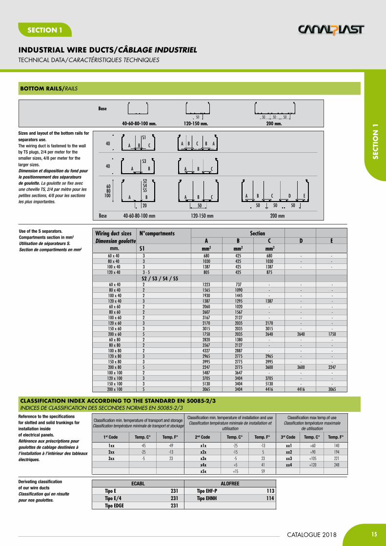
cLaSSification indeX accordinG to tHe Standard en 50085-2/3INDICEs DE CLAssIFICATION DEs sECONDEs NORMEs EN 50085-2/3
BottoM raiLS/RAILs
mm.
s2 / s3 / s4 / s5
40-60-80-100 mmBase 120-150 mm
40S1
A CB
40 A
A AB BC
B
S3
5020
6080
100 A CBA B
S2S4S5
Use of the S separators. Compartments section in mm2 Utilisation de séparateurs S.Section de compartiments en mm2
Wiring duct sizes n°compartments section a B c d e s1 mm2 mm2 mm2
60 x 40 3 680 425 680 - - 80 x 40 3 1030 425 1030 - - 100 x 40 3 1387 425 1387 - - 120 x 40 3 - 5 805 425 875
60 x 40 2 1223 737 - - - 80 x 40 2 1565 1090 - - - 100 x 40 2 1930 1445 - - - 120 x 40 3 1387 1295 1387 - - 60 x 60 2 2060 1020 - - - 80 x 60 2 2607 1567 - - - 100 x 60 2 3167 2127 - - - 120 x 60 3 2170 2035 2170 - - 150 x 60 3 3015 2035 3015 - - 200 x 60 5 1750 2035 2640 2640 1750 60 x 80 2 2820 1380 - - - 80 x 80 2 3567 2127 - - - 100 x 80 2 4327 2887 - - - 120 x 80 3 2965 2775 2965 - - 150 x 80 3 3995 2775 3995 - - 200 x 80 5 2247 2775 3600 3600 2247 100 x 100 2 5487 3647 - - - 120 x 100 3 3705 3404 3705 - - 150 x 100 3 5130 3404 5130 - - 200 x 100 5 3065 3404 4416 4416 3065
Sizes and layout of the bottom rails for separators use.The wiring duct is fastened to the wall by TS plugs, 2/4 per meter for the smaller sizes, 4/8 per meter for the larger sizes. Dimension et disposition du fond pour le positionnement des séparateurs de goulotte. La goulotte se fixe avec une cheville TS, 2/4 par mètre pour les petites sections, 4/8 pour les sections les plus importantes.
Reference to the specifications for slotted and solid trunkings for installation insideof electrical panels. Référence aux préscriptions pour goulottes de cablage destinées à l’installation à l’intérieur des tableaux électriques.
Derivating classification of our wire ductsClassification qui en résulte pour nos goulottes.
200 mm
50 50 50
A C D EB
Base
120-150 mm.50
200 mm.50 50 50
40-60-80-100 mm.
A CB
EcaBl alOFrEETipo e 231 Tipo eHf-p 113Tipo e/4 231 Tipo eHnH 114Tipo edge 231
Classification min. temperature of transport and storage Classification température minimale de transport et stockage
Classification min. temperature of installation and useClassification température minimale de installation et
utilisation
Classification max temp.of useClassification température maximale
de utilisation
1st code temp. c° temp. F° 2nd code temp. c° temp. F° 3rd code temp. c° temp. F°
1xx -45 -49 x1x -25 -13 xx1 +60 1402xx -25 -13 x2x -15 5 xx2 +90 1943xx -5 23 x3x -5 23 xx3 +105 221
x4x +5 41 xx4 +120 248x5x +15 59
Dimension goulotte

16
INDUSTRIAL WIRE DUCTS/CÂBLAGE INDUSTRIEL
CATALOGUE 2018
SECTIoN 1
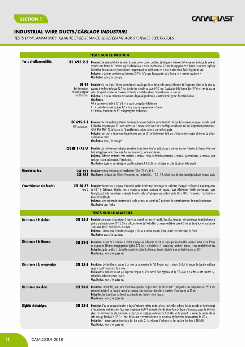
TESTS Of fLAMMAbILITY, QUALITY AND RESISTANCE REfERRED TO ELECTRICAL SYSTEMS
Test on printout
Description: the test simulates the effect of small flames caused by faulty conditions inside electrical equipment. The test piece is subjected to a 12 mm long flame produced by a burner whose nozzle has a diameter of 0.5 mm. Propagation of the flame is tested by placing under the specimen a layer of material of the components which in reality surround the part and a sheet of tissue paper.Evaluation: the duration of combustion is less than 30” and the flame does not propagate to the underlying material.Classification: pass/fail.
Description: the test simulates the effect of small flames caused by faulty conditions inside electrical equipment. The test piece is subjected to a 12.7 mm long flame produced by a nozzle with diameter of 9.5 mm.The flame is applied for 10”, repeating this for a further 10” after extinguishing of the fire. Propagation of the flame is tested by placing dry cotton wool under the specimen.Evaluation: the duration of combustion is less than the set time and there are few drips of flamed material.Classification:VO: combustion stops within 10” without flame propagation. V1: combustion stops within 30” without flame propagation. V2: combustion stops within 30” with flame propagation.
Description: this test simulates the thermal stresses produced by heat or ignition sources such as overloaded resistors or glowing metal elements. The specimen is clamped for 30” with the force of 1 Newton against the tip of a glowing metal wire with specified temperatures (750, 850, 950°C). A sheet of paper and board are placed under the specimen. Evaluation: extinguishing of the flame and ceasing of glowing within 30” from removal of the wire, no ignition of the paper and no scorching on the board.Classification: pass/fail.
Description: the test gives an approximate indication of the reaction to fire of a material during the initial phase of a fire. The flame, 40 mm high, is applied on both faces of a vertical specimen, on the lower edge.Evaluation: various parameters are considered and set, according to specified formulae: post-combustion time, post-glowing time, damaged area, dripping. Classification: on the basis of the calculation procedures categories I, II, III, IV are assigned in decreasing order of safety.
Description: combination of the classifications CSE RF 1 and CSE RF 3.Classification: six classes are defined: 0 (non-combustible material), 1, 2, 3, 4, and 5, through the combination of the categories obtained from the two tests.
Description: the presence of a certain number of substances in fumes generated by the product at a temperature of 80°C is gauged. The substances measured are: carbon dioxide, carbon monoxide, hydrochloric acid, hydrobromic acid, hydrofluoric acid, hydrocyanic acid, sulphur dioxide, hydrogen sulphide, nitrogen oxides (NO+NO 2), ammonia, acrylonitrile, formaldehyde.Evaluation: according to a predefined formula, a toxicity rating is obtained (from 0 onwards) from the quantities of all the substances measured. Classification: according to the rating. (ENEL, the Italian electricity board, for example, sets 5 as maximum acceptability and the Italian navy 2.5).
Description: the temperature at which the material, under load, starts to soften, is measured. A test piece of a pipe cut longitudinally is brought to a temperature of 90°C. A steel ball, 5 mm in diameter, is pressed against the inner surface of the test piece with a force of 20 Newton. After 1 hour the ball is removed. Evaluation: the diameter of the imprint left by the ball on the surface, measured cold, must not be more than 2 mm.Classification: pass/fail.
Description: the resistance to the prolonged action of a flame is measured. The test consists in subjecting a piece of pipe to the action of a 100 mm flame (energy produced: 775 Kcal/h) slanting 45° upwards for 1 minute. The test is repeated three times.Evaluation: after this time, if the test piece burns through self-combustion, the flames must extinguish within 30”.Classification: pass/fail.
Description: the pipe test piece is subjected to compression of 750 Newton for 1 minute. The variation in the external diameter, before and after removal of the force, is measured. Evaluation: the diameter must not exceed the original one by 25% with the force still applied, and by 20% after the force has been removed. The test pieces must not crack.Classification: pass/fail.
Description: the test piece, after being kept for 10 days in an oven at 60°C, is brought to the temperature of -25°C and then subjected to impact through the falling of a hammer, whose weight varies according to the diameter, from a height of 20 cm. Evaluation: the test pieces must not show fractures or cracks. Classification: pass/fail.
Description: a test to determine the degree of insulation, performed in two phases. The U-bent pipe is immersed, except for its ends, in water at a temperature of 20°C and filled with water. After 24 hours’ immersion, a voltage of 2000V ac is applied to two electrodes, one inside the pipe the other in the receptacle, at a frequency of 50Hz, for 15 minutes. The same pipe is immersed in water at 60°C and after two hours the electrical resistance is measured, applying a continuous voltage of 500V.Evaluation: 1) there must be no perforations of the pipe. 2) the insulation resistance must not be below 100 MΩ.Classification: pass/fail.
flammability tests. IEC 695-2-2
UL 94Vertical positioning(standard in force
in the USA)
IEC 695-2-1 (Glow Wire)
CSE RF 1/75/A
fire reaction class. CSE RF1CSE RF3
characterisation of fumes. CEI 20-37Part 2
Heat resistance. CEI 23-8
flame resistance. CEI 23-8
compressive strength. CEI 23-8
impact resistance. CEI 23-8
Tests on material
CEI 23-8dielectric resistance.
17CATALOGUE 2018
INDUSTRIAL WIRE DUCTS/CÂBLAGE INDUSTRIEL
SECT
IoN
1
SECTIoN 1
TECHNICAL DATA
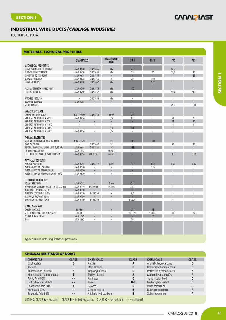
MateriaLS’ tecHnicaL ProPertieS
cHeMicaL reSiStance of noryL
ChemiCals Class ChemiCals Class ChemiCals ClassEthyl acetate C Alcalis A Aromatic hydrocarbons CAcetone C Ethyl alcohol C Chlorinated hydrocarbons CMineral acids (diluited) A Isopropyl alcohol C Potassium hydroxide 50% AMineral acids (concentrated) B Methyl alcohol A Sodium hydroxide 50% AAcetic Acid 90% - - Antifreeze C Transmission fluid CHydrochloric Acid 37% - - Petrol B-C Methacrylate sealant CPhosphoric Acid 60% A Ketones C White mineral oil - -Nitric Acid 90% - - Greases and oil B Detergent solutions ASulphuric Acid 98% - - Aliphatic hydrocarbons B Solvents/Alcohols A
LEGEND: CLASS A = resistant; CLASS B = limited resistance; CLASS C = not resistant; - - = not tested.
Typicals values. Data for guidance purposes only.
EHF-PEHNHMEASuREMENTuNITSTANDARDS PVC ABS
MECHANICAl PROPERTIESTENSILE STRENGTH TO yELD POINT ASTM D 638 DIN 53455 MPa 64 - 46,2 - ULTIMATE TENSILE STRENGTH ASTM D 638 DIN 53455 MPa 53 60 37,3 40ELONGATION TO yELD POINT ASTM D 638 DIN 53455 % - - - 25ULTIMATE ELONGATION ASTM D 638 DIN 53455 % 20 >50 - -TENSILE MODULUS ASTM D 638 DIN 53457 MPa - 2500 - -
FLExURAL STRENGTH TO yELD POINT ASTM D 790 DIN 53452 MPa 100 - - - FLExURAL MODULUS ASTM D 790 DIN 53457 MPa - - 2736 2400
HARDNESS H358/30 - DIN 53456 MPa - - - - ROCKWELL HARDNESS ASTM D 758 - - - - - - SHORE HARDNESS - - - - - 79 D 110 R
IMPACT RESISTANCE CHARPy TEST, WITH NOTCH ISO 179/1eA DIN 53453 KJ/m2 20 - - -IzOD TEST, WITH NOTCH, AT 23°C ASTM D 256 - J/m 300 - 74 70IzOD TEST, WITH NOTCH, AT 0°C - - - - - 41 40IzOD TEST, WITH NOTCH, AT -10°C - - - - - 4 5IzOD TEST, WITH NOTCH, AT -30°C - - J/m 181 - - -IzOD TEST, WITH NOTCH, AT -40°C ASTM D 256 - J/m - - - -
THERMAl PROPERTIES SOFTENING TEMPERATURE, VICAT METHOD B ASTM D 1525 - °C 143 130 VICAT VST/B/120 - DIN 53460 °C - - 76 95DEFORM. TEMPERATURE UNDER LOAD, 1,82 MPa ASTM D 648 DIN 53461 °C 122 - - -THERMAL CONDUCTIVITy ASTM C 117 - W/m°C - - - -COEFFICIENT OF LINEAR THERMAL ExPANSION ASTM D 696 VDE 0304/1 m/m°C - - 0,1 0,19
PHySICAl PROPERTIESPHySICAL PROPERTIES ASTM D 792 DIN 53479 g/cm3 1,11 1,19 1,55 1,05WATER ABSORPTION, 24 HOURS ASTM D 570 - % - 0,15 - -WATER ABSORPTION AT EQUILIBRIUM ASTM D 570 - % - - - -WATER ABSORPTION AT EQUILIBRIUM AT 100°C ASTM D 570 - % - - - -
ElECTRICAl PROPERTIESVOLUME RESISTIVITy ASTM D 257 - Ohm-m >762 - - -ISTANTANEOUS DIELECTRIC RIGIDITy, IN OIL, 3,2 mm ASTM D 149 IEC 60243-1 Kv/mm 34,1 - - -DIELECTRIC CONSTANT AT 50 Hz ASTM D 150 - - - - - -DIELECTRIC CONSTANT AT 1 MHz ASTM D 150 IEC 60250 - 2,7 - - -DISSIPATION FACTOR AT 50 Hz ASTM D 150 - - - - - -DISSIPATION FACTOR AT 1 MHz ASTM D 150 IEC 60250 - 0,0029 - - -
FlAME RESISTANCEOxyGEN INDEx (LOI) ISO 4589 - % 33 28 - -SELF-ExTINGUISHING (mm of thickness) UL 94 - - V-0 (1,5) V-0(1,6) V-0 V-2OPTICAL DENSITy, 90 sec. ASTM E 662 - - - 80 - -4 min ASTM E 662 - - 30 - - -
18
INDUSTRIAL WIRE DUCTS/CÂBLAGE INDUSTRIEL
CATALOGUE 2018
SECTIoN 1
tEStS D’iNfLaMMaBiLité, QUaLité Et RéSiStaNcE SE RéféRaNt aUx SYStèMES éLEctRiQUES
Description: le test simule l’effet de petites flammes causées par des conditions défectueuses à l’intérieur de l’équipement électrique. La pièce est soumise à une flamme de 12 mm de long d’un brûleur dont la buse a un diamètre de 0,5 mm. La propagation de la flamme est contrôlée en plaçant l’échantillon dans une couche de matériau des composants qui, en réalité, autour de la pièce à usiner et une feuille de papier de soie.Évaluation: la durée de combustion est inférieure à 30 “et il n’y a pas de propagation de la flamme sur le matériau sous-jacent ».Classification: passe / ne passe pas.
Description: Le test simule l’effet de petites flammes causées par des conditions défectueuses à l’intérieur de l’équipement électrique. La pièce est soumise à une flamme longue 12,7 mm à partir d’un diamètre de buse de 9,5 mm. L’application de la flamme dure 10 “et est répétée pour un autre 10” après l’extinction de l’incendie. La flamme se produit en plaçant l’échantillon dans un coton sec.Évaluation: la durée de combustion est inférieure à la période pré-établie et se détache moins gouttes de matière brûlante.Classification:VO: la combustion s’arrête à 10“ et il n’y a pas de propagation de la flamme.V1: la combustion s’arrête dans les 30“ et il n’y a pas de propagation de la flamme.V2: arrête de brûler moins de 30“ et la propagation des flammes.
Description: Ce test simule les contraintes thermiques des sources de chaleur ou d’inflammation tels que des résistances surchargées ou métal chaud. L’échantillon est pressé pour 30“ avec une force de 1 Newton sur le bout d’un fil métallique incandescent avec des températures prédéterminées (750, 850, 950 ° C). Au-dessous de l’échantillon sont placés un carton et une feuille de papier.Évaluation: extinction et terminaison d’incandescence avant de 30“ de l’enlèvement du fil, pas d’inflammation du papier et absence de brûlures sur la boîte en carton.Classification: passe / ne passe pas.
Description: Le test donne une indication générale de la réaction au feu d’un matériel dans la première phase de l’incendie. La flamme, 40 mm de haut, est appliquée sur les deux faces d’un spécimen vertical, sur le bord inférieur.Évaluation: Différents paramètres sont examinés et composés selon des formules préétablies: le temps de postcombustion, le temps de post-décharge, la zone endommagée, l’égouttement.Classification: Basée sur les méthodes de calcul les catégories I, II, III, IV sont attribuées par ordre décroissant de la sécurité.
Description: est une combinaison de classifications CST et CSE RF 3 RF 1.Classification: six classes sont définies: 0 (matériaux non combustibles), 1, 2, 3, 4, 5, grâce à la combinaison des catégories issues des deux essais.
Description: la mesure de la présence d’un certain nombre de substances dans les gaz de combustion développés par le produit à une température de 80 ° C. Substances détectées sont: le dioxyde de carbone, monoxyde de carbone, l’acide chlorhydrique, l’acide bromhydrique, l’acide fluorhydrique, l’acide cyanhydrique, le dioxyde de soufre, sulfure d’hydrogène, des oxydes d’azote (NO + NO 2), l’ammoniac, l’acrylonitrile, le Formica formaldéhyde.Évaluation: selon une formule prédéterminée il résulte un indice de toxicité (de 0 au dessus) des quantités détectées de toutes les substances.Classification: selon l’indice.
Description: on mesure la température à laquelle un matériel commence à ramollir. Une pièce d’essai de tube est découpé longitudinalement et porté à une température de 90 ° C. Sur la surface intérieure de l’ échantillon on presse une bille en acier de 5 mm de diamètre, avec une force de 20 Newton. Après 1 heure la bille est enlevée.Évaluation: Le diamètre de l’empreinte laissée par la bille sur la surface, mesurée à froid, ne doit pas être majeure de 2 mm.Classification: passe / ne passe pas.
Description: mesure de la résistance à l’action prolongée de la flamme. Le test est réalisé par un échantillon soumis à l’action d’une flamme de longueur de 100 mm (énergie produite égale à 775 Kcal / h) inclinée à 45 ° vers le haut, pendant 1 minute. Le test est répété trois fois.Évaluation: Après ce délai, si l’échantillon continue à brûler, les flammes doivent s’éteindre dans un délai de moins de 30”.Classification: passe / ne passe pas.
Description: L’échantillon est soumis à un force de compression de 750 Newton pour 1 minute. On fait la mesure du diamètre extérieur, après et avant l’application de la force.Évaluation: Le diamètre ne doit pas dépasser l’original du 25% avec la force appliquée et du 20% après que la force a été éliminée. Les échantillons doivent être sans fissures.Classification: passe / ne passe pas.
Description: Léchantillon, après avoir été maintenu pendant 10 jours dans une étuve à 60° C, est porté à une température de -25° C et il est soumis ensuite à un choc par chute d’un marteau, dont la masse varie selon le diamètre, d’une hauteur de 20 cm.Évaluation: Les échantillons ne doivent pas présenter des fractures ni des fissures.Classification: passe / ne passe pas.
Description: C’est un test pour déterminer le degré d’isolement, réalisée en deux phases. L’échantillon en forme de tube recourbé en U est immergé, à l’exception des extrémités, dans l’eau à une température de 20° C et remplie d’eau lui même. Après 24 heures d’immersion, à deux des électrodes placés l’un à l’intérieur du tube, l’autre dans le bassin, lui est appliquée une tension de 2000 VAC, 50 Hz, pendant 15 minutes. Le mêmes tube est enfin immergé dans l’eau à 60° C et l’après deux heures la résistance électrique est mesurée en appliquant une tension continue de 500 V.Évaluation: 1) Aucune perforation du tube doit être notée. 2) La résistance d’isolement ne doit pas être inférieure à 100 MΩ.Classification: passe / ne passe pas.
teStS SUr Le ProdUit
Tests d’inflammabilité. IEC 695-2-2
UL 94Position verticale
(Norme en vigueuraux États-Unis)
IEC 695-2-1 (Fil incandescent)
CSE RF 1/75/A
réaction au feu. CSE RF1CSE RF3
caractérisation des fumées. CEI 20-37Partie 2
résistance à la chaleur. CEI 23-8
résistance à la flamme. CEI 23-8
résistance à la compression. CEI 23-8
résistance aux chocs. CEI 23-8
teStS SUr Le MaterieL
CEI 23-8rigidité diélectrique.

19CATALOGUE 2018
INDUSTRIAL WIRE DUCTS/CÂBLAGE INDUSTRIEL
SECT
IoN
1
SECTIoN 1
caRactéRiStiQUES tEcHNiQUES
caractériStiQUeS tecHniQUeS deS MatériaUX
réSiStance cHiMiQUe dU noryL
Produits Chimiques Class Produits Chimiques Class Produits Chimiques ClassAcétate d'éthyle C Alcali A Hydrocarbures aromatiques CAcétone C Alcool éthylique C Hydrocarbures chlorés CMinéraux acides (faible) A Alcool isopropylique C Hydroxyde de potassium à 50% AMinéraux acides (forts) B Alcool méthylique A Hydroxyde de sodium à 50% AAcide acétique à 90% - - Antigel C Liquide de transmission CAcide chlorhydrique à 37% - - Petrol B-C Mastic acrylique CAcide phosphorique 60% A Cétones C Huile minérale - -Acide nitrique 90% - - Graisses et huiles B Solutions de nettoyage AAcide sulfurique 98% - - Hydrocarbures aliphatiques B Solvants/alcools A
LÉGENDE: CLASS A = résistant; CLASS B = résistance limitée; CLASSE C = pas résistant; - - = pas testé.
Données uniquement à des fins d’orientation.
PVC EHF-PEHNHuNITÉ DE MESuRENORMES ABS
CARACTÉRISTIQuES MÉCANIQuESRÉSISTANCE à LA TRACTION AU SEUIL D’ÉCOULEMENT ASTM D 638 DIN 53455 MPA 64 - 46,2 -RÉSISTANCE à LA RUPTURE ASTM D 638 DIN 53455 MPA 53 60 37,3 40ALLONGEMENT AU SEUIL D’ÉCOULEMENT ASTM D 638 DIN 53455 % - - - 25ALLONGEMENT à LA RUPTURE ASTM D 638 DIN 53455 % 20 >50 - -MODULE DE TRACTION ASTM D 638 DIN 53457 MPA - 2500 - -
RÉSISTANCE à LA FLExION à RENDEMENT ASTM D 790 DIN 53452 MPA 100 - -MODULE à LA FLExION ASTM D 790 DIN 53457 MPA - - 2736 2400
DURETÉ H358/30 - DIN 53456 MPA - - - -DURETÉ ROCKWELL ASTM D 758 - - - - - -DURETÉ SHORE - - - - - 79 D 110 R
RÉSISTANCE Au CHOC TEST CHARPy, AVEC CRANTÉE ISO 179/1EA DIN 53453 KJ/M2 20 - - -TEST IzOD, AVEC CRANTÉE à 23° ASTM D 256 - J/M 300 - 74 70TEST IzOD, AVEC CRANTÉE à 0° - - J/M - - 41 40TEST IzOD, AVEC CRANTÉE à -10° - - J/M - - 4 5TEST IzOD, AVEC CRANTÉE à -30° - - J/M 181 - - -TEST IzOD, AVEC CRANTÉE à -40°C ASTM D 256 - J/M - - - -
PROPRIETES THERMIQuES TEMPÉRATURE DE RAMOLLISSEMENT VICAT, MÉTHODE B ASTM D 1525 - °C 143 130 - -VICAT VST/B/120 - DIN 53460 °C - - 76 95TEMP. DE DÉFORMATION SOUS CHARGE, 1,82 MPA ASTM D 648 DIN 53461 - 122 - - -CONDUCTIVITÉ THERMIQUE ASTM C 117 - W/M°C - - - -COEFFICIENT DE DILATATION THERMIQUE LINÉAIRE ASTM D 696 VDE 0304/1 M/M°C - - 0,1 0,19
PROPRIETES PHySIQuESPOIDS SPÉCIFIQUE ASTM D 792 DIN 53479 g/cm3 1,11 1,19 1,55 1,05ABSORPTION D’EAU, 24 HEURES ASTM D 570 - % - 0,15 - -ABSORPTION D’EAU à L’ÉQUILIBRE ASTM D 570 - % - - - -ABSORPTION D’EAU à L’ÉQUILIBRE à 100°C ASTM D 570 - % - - -
PROPRIÉTÉS ÉlECTRIQuESRÉSISTIVITÉ VOLUMIQUE ASTM D 257 - OHM-M >762 - - -INSTANTANÉE RIGIDITÉ DIÉLECTRIQUE, DANS L’HUILE, 3,2 MM IEC 60243-1 - KV/MM 34,1 - - -CONSTANTE DIÉLECTRIQUE à 50 Hz ASTM D 150 - - - - - -CONSTANTE DIÉLECTRIQUE à 1 MHz IEC 60250 - - 2,7 - - -FACTEUR DE DISSIPATION à 50 Hz ASTM D 150 - - - - - -FACTEUR DE DISSIPATION à 1 MHz IEC 60250 - - 0,0009 - - -
COMPORTEMENT Au FEuINDICE D’OxyGèNE ASTM D 2863 - % 33 28 - -AUTO-ExTINGUIBLE (ÉPAISSEUR EN MM) UL 94 - - V-0 (1,5) V-0(1,6) V-0 V-2DENSITÉ OPTIQUE, 90 SEC. ASTM E 662 - - - 80 - -4 MINUTES ASTM E 662 - - 30 - - -

20
INDUSTRIAL WIRE DUCTS/CÂBLAGE INDUSTRIEL
CATALOGUE 2018
SECTIoN 1
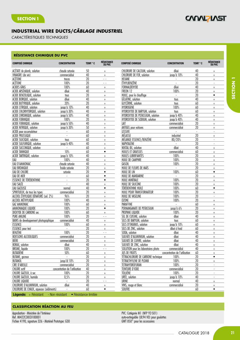
Legend: + Resistant - Not resistant • Limited resistance
Pvc reSiStance to cHeMicaL aGentS
cHEMical cOMPOUND cONcENtratiON tEMP. ° c rEsistaNcEOF PVc cHEMical cOMPOUND cONcENtratiON tEMP. ° c rEsistaNcE
OF PVc
LEAD ACETATE, solution hot saturated 50 +VINEGAR (wine) commercially available 40 +ACETONE trace 20 - -ACETONE 100% 20 - -FATTy ACIDS 100% 60 +ARSENIC ACID, solution dilute 40 +BENzOLIC ACID, solution any concentration 20 +BORIC ACID, solution dilute 40 +BUTyRIC ACID, solution 20% 20 +CITRIC ACID, solution up to 10% 40 +HyDROCHLORIC ACID, solution up to 30% 40 +CHROMIC ACID, solution up to 50% 40 +FORMIC ACID 100% 20 +FORMIC ACID, solution up to 50% 40 +NITRIC ACID, solution up to 30% 50 +BATTERy ACID - 60 +PRUSSIC ACID - 60 +SILICIC ACID, solution all concentrations and types 60 +SULPHURIC ACID, solution up to 40% 40 +SUCCINIC ACID, solution - 60 +TANNIC ACID 10% 60 •TARTARIC ACID, solution up to 10% 40 +WATER 100% 40 +AMMONIA WATER hot saturated 40 +BROMINE WATER cold saturated 20 +CHLORINE WATER saturated 20 •SEA WATER - 60 •WHITE SPIRIT - 20 •SALT WATER - 40 +CARBONATED WATER normal 40 •AQUA VITAE, all types commercially available 20 +DENATURED ETHyL ALCOHOL (sol. 2%) 96% 20 +METHyL ALCOHOL 100% 40 +AMMONIA GAS 100% 60 +LIQUID AMMONIA 100% 20 •CARBON DIOxIDE dry 100% 60 +PURE ANILINE 100% 20 - -PHOTOGRAPHIC DEVELOPMENT BATHS commercially available 40 +PETROL 100% 60 +PETROL for tests - 20 +BENzOL 100% 20 - -ALCOHOLIC DRINKS commercially available 20 +BEER commercially available 20 +BORAx, solution dilute 40 +BROMINE, liquid 100% 20 - -BUTADIENE 50% 60 +BUTANE, gas - 20 +BUTANOL up to 10% 20 +BEESWAx commercially available 20 +CHLORINE active usual concentration 40 +CHLORINE GAS, dry 100% 20 +CHLORINE GAS, wet 0,5% 20 +LIQUID CHLORINE - 20 - -ALUMINIUM CHLORIDE, solution dilute 40 +CALCIUM CHLORIDE, aqueous (sedim.) - 60 •
CALCIUM CHLORIDE, solution dilute 40 +IRON CHLORIDE, solution up to 10% 40 +HExANE - 20 +ETHyL BENzOL - 20 -FORMALDEHyDE dilute 40 +FREON 12 100% 20 +OIL, heating - 20 •GELATINE, solution all concentrations and types 40 +GLyCERINE, solution all concentrations and types 60 +HyDROGEN 100% 60 +BARIUM HyDROxIDE, solution all concentrations and types 60 +POTASSIUM HyDROxIDE, solution up to 40% 40 +SODIUM HyDROxIDE, solution up to 40% 40 +MILK commercially available 20 +LIQUID ANTIFREEzE, for motor vehicles commercially available 20 +LyE - - -MOLASSES industrial concentrate 20 +PETROL/BENzOL MIxTURE 80/20% 20 -NAPHTHALENE - 20 -NEKTAL Bx, solution dilute 40 +OILS AND GREASES commercially available 60 +LUBRICATING OILS 100% 20 +CAMPHOR OIL 100% 20 +DIESEL OIL 100% 20 +CORNFLOWER OIL - 20 +LINSEED OIL 100% 60 •MANDARIN OIL - 20 +MINERAL OIL 100% 20 +SILICONE OIL 100% 20 +TURPENTINE OIL 100% 60 •TRANSFORMER OIL 100% 20 +LIQUID PARAFFIN 100% 20 -OzONE 100% 20 +PARAFFIN - 60 +POTASSIUM PERMANGANATE up to 6% 20 +LIQUID PROPANE 100% 20 +COOKING SALT, solution dilute 40 +BARIUM SALTS, solution all concentrations 60 +FERTILIzER SALTS, solution up to 10% 60 +zINC SALTS, solution cold diluted 60 +SODIUM CARBONATE, solution dilute 40 +ALUMINIUM SULPHATE, solution dilute 40 +COPPER SULPHATE, solution dilute 40 +zINC SULPHATE, solution dilute 40 +SOLUTION for photographic laboratories commercially available 40 +FRUIT JUICES usual concentration 60 +CARBON TETRACHLORIDE technical 100% 20 •TETRAETHyL LEAD 100% 20 +TETRAHyDROFURAN 100% 20 -TINCTURE OF IODINE commercially available 20 -TOLUENE 100% 20 -UREA, solution up to 10% 40 -URINE normal 40 +WINES, red and white commercially available 20 +SULPHUR - 60 •
fLaMe reSiStance
Italian Ministry of Interiors Approval Cod. MI422C30CD100001 File 4190, sub. 326 - Material prototype: G30
PVC: Class M1 (NFP 92-501) Self-extinguishing (UL94 V0) for trunkingGWT 850° for accessories
TECHNICAL DATA
21CATALOGUE 2018
INDUSTRIAL WIRE DUCTS/CÂBLAGE INDUSTRIEL
SECT
IoN
1
SECTIoN 1
Légende: + Résistant - Non résistant • Résistance limitée
réSiStance cHiMiQUe dU Pvc
cOMPOsé cHiMiqUE cONcENtratiON tEMP. ° c résistaNcEDU PVc cOMPOsé cHiMiqUE cONcENtratiON tEMP. ° c résistaNcE
DU PVc
ACÉTATE de plomb, solution chaude saturée 50 +VINAIGRE (de vin) commercialisé 40 +ACÉTONE traces 20 - -ACÉTONE 100% 20 - -ACIDES GRAS 100% 60 +ACIDE ARSÉNIQUE, solution dilué 40 +ACIDE BENzOLIQUE, solution tous 20 +ACIDE BORIQUE, solution dilué 40 +ACIDE BUTyRIQUE, solution 20% 20 +ACIDE CITRIQUE, solution jusqu’à 10% 40 +ACIDE CHLORHyDRIQUE, solution jusqu’à 30% 40 +ACIDE CHROMIQUE, solution jusqu’à 50% 40 +ACIDE FORMIQUE 100% 20 +ACIDE FORMIQUE, solution jusqu’à 50% 40 +ACIDE NITRIQUE, solution jusqu’à 30% 50 +ACIDE pour accumulateur - 60 +ACIDE PRUSSIQUE - 60 +ACIDE SILICIQUE, solution tous 60 +ACIDE SULFURIQUE, solution jusqu’à 40% 40 +ACIDE SUCCINIQUE, solution - 60 +ACIDE TANNIQUE 10% 60 •ACIDE TARTRIQUE, solution jusqu’à 10% 40 +EAU 100% 40 +EAU D’AMMONIAC chaude saturée 40 +EAU BROMIQUE froide saturée 20 +EAU DE CHLORE saturée 20 •EAU DE MER - 60 •ESSENCE DE TÉRÉBENTHINE - 20 •EAU SALÉE - 40 +EAU GAzEUSE normal 40 •SPIRITUEUx, de tous les types commercialisé 20 +ALCOOL ÉTHyLIQUE DÉNATURÉ (sol. 2%) 96% 20 +ALCOOL MÉTHyLIQUE 100% 40 +GAz AMMONIAC 100% 60 +AMMONIAQUE LIQUIDE 100% 20 •DIOxyDE DE CARBONE sec 100% 60 +PURE ANILINE 100% 20 - -BAINS de developpement photographique commercialisé 40 +ESSENCE 100% 60 +ESSENCE pour test - 20 +BENzèNE 100% 20 - -BOISSONS ALCOOLIQUES commercialisé 20 +BIèRE commercialisé 20 +BORAx, solution dilué 40 +BROME, liquide 100% 20 - -BUTADIèNE 50% 60 +BUTANE, gazeux - 20 +BUTANOL jusqu’àl 10% 20 +CIRE D’ABEILLE commercialisé 20 +CHLORE actif concentration de l’utilisation 40 +CHLORE GAzEUx, à sec 100% 20 +CHLORE GAzEUx, humide 0,5% 20 +CHLORE LIQUIDE - 20 - -CHLORURE D’ALUMINIUM, solution dilué 40 +CHLORURE DE CHAUx, aqueuse (sédiments) - 60 •
CHLORURE DE CALCIUM, solution dilué 40 +CHLORURE DE FER, solution jusqu’à 10% 40 +HExANE - 20 +ÉTHyLBENzèNE - 20 -FORMALDÉHyDE dilué 40 +FREON 12 100% 20 +HUILE, pour le chauffage - 20 •GÉLATINE, solution tous 40 +GLyCÉRINE, solution tous 60 +HyDROGENE 100% 60 +HyDROxyDE DE BARyUM, solution tous 60 +HyDROxyDE DE POTASSIUM, solution jusqu’à 40% 40 +HyDROxyDE DE SODIUM, solution jusqu’à 40% 40 +LAIT commercialisé 20 +ANTIGEL pour voitures commercialisé 20 +LESSIVE - - -MÉLASSE industriel 20 +MÉLANGE ESSENCE/BENzèNE 80/20% 20 -NAPHTALèNE - 20 -NEKTAL Bx, solution dilué 40 +HUILES ET GRAISSES commercialisé 60 +HUILES LUBRIFIANTES 100% 20 +HUILE DE CAMPHRE 100% 20 +GASOIL 100% 20 +HUILE DE FLEURS DE MAÏS - 20 +HUILE DE LIN 100% 60 •HUILE DE MANDARINE - 20 +HUILE MINÉRALE 100% 20 +HUILE DE SILICONE 100% 20 +TÉRÉBENTHINE HUILE 100% 60 •HUILE POUR TRANSFORMATEUR 100% 20 +HUILE DE VASELINE 100% 20 -OzONE 100% 20 +PARAFFINE - 60 +PERMANGANATE DE POTASSIUM jusqu’à 6% 20 +PROPANE LIQUIDE 100% 20 +SEL DE CUISINE, solution dilué 40 +SELS DE BARyUM, solution tous 60 +SELS D’ENGRAIS, solution jusqu’à 10% 60 +SELS DE zINC, solution dilué à froid 60 +SODA, solution dilué 40 +SULFATE D’ALUMINIUM, solution dilué 40 +SULFATE DE CUIVRE, solution dilué 40 +SULFATE DE zINC, solution dilué 40 +SOLUTION pour les laboratoires photo commercialisé 40 +JUS DE FRUITS concentration de l’utilisation 60 +TÉTRACHLORURE DE CARBONE technique 100% 20 •TETRAETHyLENE DE PLOMB 100% 20 +TETRAHyDROFURAN 100% 20 -TEINTURE D’IODE commercialisé 20 -TOLUèNE 100% 20 -URÉE, solution jusqu’à 10% 40 -URINE normal 40 +VINS, rouge et blanc commercialisé 20 +SOUFRE - 60 •
cLaSSification réaction aU feU
Approbation - Ministère de l’IntérieurRef. MI422C30CD100001Fichier 4190, signature 326 - Matériel Prototype: G30
PVC: Catégorie M1 (NFP 92-501)auto-extinguible (UL94 V0) pour goulottesGWT 850° pour les accessoires
caRactéRiStiQUES tEcHNiQUES

22
INDUSTRIAL WIRE DUCTS/CÂBLAGE INDUSTRIEL
CATALOGUE 2018
SECTIoN 1
ACCESSORIES/OUtiLS
“cP” SPiraLsPIRALE “CP”HALOGEN FREE / sAns HALogens
“GUeSt” eXtenSiBLe StocKinG SHeatHSGAINEs TREsséEs EXTENsIBLEs “GUEsT”RoHS cOmpLIaNcE
“fLX” fLeXiBLe dUctS to GatHer tHe caBLeSWITH aDHESIvE ON THE bOTTOm. maTERIaL: pOLYpROpYLENEGOULOTTEs FLEXIBLE POUR REGROUPER LEs CÂBLEsAvec AdHésif Au fond. MAtérieL: poLypropyLène
RoHS cOmpLIaNcE -15°/ +80° SElF-EXTINGuISHING ul94-V2
CODERÉFÉRENCE
Ø mm
A b
mAx ElAStiCityOF tUbinG
MAx ÉLAstiCitÉ du tuBE Ø MM
COlOURCouLEuR
PACK mEMB. m
CP3 1,5 3 2-12 T 400 (8x50)CP6 4,2 6 5-50 T 200 (8x25)CP8 6,0 8 8-70 T 100 (4x25)CP10 7,6 10 12-100 T 100 (4x25)CP12 9,6 12 14-120 T 100 (4x25)CP14 11,6 14 18-140 T 60 (3x20)CPA3 1,5 3 2-12 A 400 (8x50)CPA6 4,2 6 5-50 A 200 (8x25)CPA10 7,6 10 12-100 A 100 (4x25)CPA12 9,6 12 14-120 A 100 (4x25)CPn3 1,5 3 2-12 400 (8x50)CPn6 4,2 6 5-50 200 (8x25)CPn8 6,0 8 8-70 100 (4x25)CPn10 7,6 10 12-100 100 (4x25)CPn12 9,6 12 14-120 100 (4x25)T = Transparent
A = White self-extinguishing V2 / Blanc auto-extinguible V2
= Black not self-extinguishing / Noir non auto-extinguible
CODERÉFÉRENCE
Ø mmCOlOURCouLEuR
PACK mEMB. m
GUESt 05 5 10 200
GUESt 10 10 18 200
GUESt 20 20 30 100
GUESt 30 30 45 100
GUESt 50 50 75 50
Suitable for flexible electrical wire and cables, the extensible sheath protects the wires from abrasion and improves the thermal and electrical isolation. The GUEST sheath allows pulling wires out off the mesh at different locations.Convient pour les câbles électriques flexibles, la gaine facilite la protection extensible contre l’abrasion et améliore l’isolation thermique et électrique. Vous permet de gainer les faisceaux de câbles avec des diamètres très différents, permettant l’évacuation des fils individuels à travers les boucles écartées.Matériau: Polyester Monofilament
CODERÉFÉRENCE
b H lCOlOURCouLEuR
PACK Pcs.EMB. Pcs.
Flx10 12,5 12,5 500 50
Flx20 20 20 500 50
Flx30 30 30 500 50Flx40 40 40 500 50
AB
12,5
12,520
20
30
30
40
40
25
8
4,5
flX10
25 4,58
flX20flX30flX40
7,55
SPECIFICATIONS Non-toxicResistant to abrasive and combustible substances, liquids, solvents, mouldsExcellent resistance to abrasionDiameter of polyester yarn 0,22 mmWorking temperature -50°/+150°CMax continuous working temperature +120°C Max peak temperature +180°C
Flammability rating UL94 HBOxygen index LO1 27,5Melting point 257°CSoftening point 230° - 240°CWater absorption in normal climate conditions 0,4%Water absorption and saturation 0,5 - 0,6%Max elongation at break 23 - 28%Water contraction at 100° CX3 2 - 10%
INFORMATIONS TECHNIQUESAucune toxicitéRésistance à abrasif, des liquides inflammables, solvants, les moisissuresExcellente résistance à l’abrasion0,22 mm de fils de polyester de diamètreGamme de température -50 ° / +150 ° CTempérature maximale d’utilisation en continu +120 ° CLa température max 180 ° C dans l’utilisation alternée
Inflammabilité Auto-extinguible UL94 HBIndice d’oxygène 27,5 LO1257 Point de fusion ° CPoint de ramollissement 230 ° - 240 ° CAbsorption d’eau 0,40% dans le climat normeL’absorption d’eau et saturation de 0,5 à 0,6%Allongement à la rupture max 23 à 28%Pick-H2O à 100 ° CX3 2 à 10%
CODERÉFÉRENCE
DESCRiPtiOndEsCRiPtioN
Ø mmCAblES
1x2,5 mAxCOlOURCouLEuR
PACK mEMB. m
SPF08n Sheath/Gaine 8 6 100
SPF15n Sheath/Gaine 15 10 50
SPF20n Sheath/Gaine 20 14 30
SPF25n Sheath/Gaine 25 14 20PACK Pcs.EMB. Pcs.
SPFUt08 Tool/outil 8 - - 10
SPFUt15 Tool/outil 15 - - 10
SPFUt20 Tool/outil 20 - - 10
SPFUt25 Tool/outil 25 - - 5
“SPifaSt” SHeatH and tooL/GAINE ET OUTIL “sPIFAsT”maTERIaL: pOLYpROpYLENE / MAtérieL: poLypropyLène
HALOGEN FREE / sAns HALogens -20°/ +90° ul94-HB

23CATALOGUE 2018
INDUSTRIAL WIRE DUCTS/CÂBLAGE INDUSTRIEL
SECT
IoN
1
SECTIoN 1
ACCESSORIES/OUtiLS
S4S3S1 S2 S5
CODERÉFÉRENCE
HPACK mEMB. m
S1 (2 Separators/2 séparateurs) 40 30
S2 60 50
S3 40 60
S4 80 32
S5 100 32
CODERÉFÉRENCE
FOR tRUnKinG bPouR GouLottE B
PACK Pcs.EMB. Pcs.
tR4 40 500 (5x100)
tR6 60 500 (5x100)
tR8 80 400 (5x80)
tR10 100/120 250 (5x50)
tR15 125 200 (1x200)
CODERÉFÉRENCE
FOR tRUnKinG bPouR GouLottE B
PACK Pcs.EMB. Pcs.
FCV12040 60/120x40 40
FCV12060 40/200x60 25
CODERÉFÉRENCE
PACK Pcs.EMB. Pcs.
DmF 100 (2x50)
CODERÉFÉRENCE
PACK Pcs.EMB. Pcs.
PtE 100 (2x50)
CODERÉFÉRENCE
PACK Pcs.EMB. Pcs.
COVit 1000
CODERÉFÉRENCE
PACK Pcs.EMB. Pcs.
PtR 100 (4x25)
caBLe SeParatorSséPARATEURs DE CABLEsRoHS cOmpLIaNcE
croSS-arMS TO RETaIN THE cabLES WHEN THE cOvER IS REmOvEDTRAVERsEs pour contenir Les fiLs éLectriques dAns Les gouLottes
RoHS cOmpLIaNcE
caBLe-retaininG croSS-arMSTRAVERsEs pour contenir Les fiLs éLectriques dAns Les gouLottes
RoHS cOmpLIaNcE
caBLe tie HoLderATTACHE DE CÂBLE PORTEURRoHS cOmpLIaNcE
LaBeL HoLder for Wire dUctSPORTE-éTIQUETTERoHS cOmpLIaNcE
croSS-arM for trUnKinGSTRAVERsE POUR LEs GOULOTTEsRoHS cOmpLIaNcE
coverS TO INSTaLL OvER IF mETaL ScREWS aRE uSED TO SEcuRE THE DucTMINI COUVERCLEs pour isoLer Les vis de fixAtion en MétAL
RoHS cOmpLIaNcE
24
INDUSTRIAL WIRE DUCTS/CÂBLAGE INDUSTRIEL
CATALOGUE 2018
SECTIoN 1
CODERÉFÉRENCE
FOR tRUnKinG HPouR GouLottE h
PACK Pcs.EMB. Pcs.
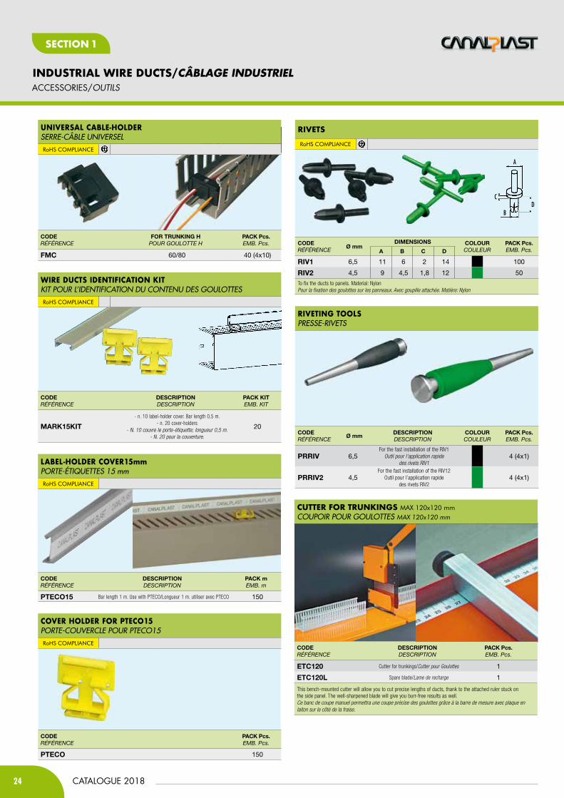
FmC 60/80 40 (4x10)
CODERÉFÉRENCE
DESCRiPtiOndEsCRiPtioN
PACK KitEMB. Kit
mARK15Kit
- n. 10 label-holder cover. Bar length 0,5 m.- n. 20 cover-holders
- N. 10 couvre le porte-étiquette; longueur 0,5 m.- N. 20 pour la couverture.
20
CODERÉFÉRENCE
DESCRiPtiOndEsCRiPtioN
PACK mEMB. m
PtECO15 Bar length 1 m. Use with PTECO/Longueur 1 m. utiliser avec PTECO 150
CODERÉFÉRENCE
PACK Pcs.EMB. Pcs.
PtECO 150
UniverSaL caBLe-HoLdersERRE-CÂBLE UNIVERsELRoHS cOmpLIaNcE
rivetS
RoHS cOmpLIaNcE
rivetinG tooLS PREssE-RIVETs
Wire dUctS identification KitKIT POUR L’IDENTIFICATION DU CONTENU DEs GOULOTTEsRoHS cOmpLIaNcE
LaBeL-HoLder cover15mmPORTE-éTIQUETTEs 15 mmRoHS cOmpLIaNcE
cover HoLder for Pteco15PORTE-COUVERCLE POUR PTECO15RoHS cOmpLIaNcE
A
BD
C
CODERÉFÉRENCE
Ø mmDimEnSiOnS COlOUR
CouLEuRPACK Pcs.EMB. Pcs.A b C D
RiV1 6,5 11 6 2 14 100
RiV2 4,5 9 4,5 1,8 12 50
To fix the ducts to panels. Material: NylonPour la fixation des goulottes sur les panneaux. Avec goupille attachée. Matière: Nylon
CODERÉFÉRENCE
Ø mmDESCRiPtiOndEsCRiPtioN
COlOURCouLEuR
PACK Pcs.EMB. Pcs.
PRRiV 6,5For the fast installation of the RIV1
Outil pour l’application rapide des rivets RIV1
4 (4x1)
PRRiV2 4,5For the fast installation of the RIV12
Outil pour l’application rapide des rivets RIV2
4 (4x1)
cUtter for trUnKinGS max 120x120 mmCOUPOIR POUR GOULOTTEs MAx 120x120 mm
CODERÉFÉRENCE
DESCRiPtiOndEsCRiPtioN
PACK Pcs.EMB. Pcs.
EtC120 Cutter for trunkings/Cutter pour Goulottes 1
EtC120l Spare blade/Lame de recharge 1
This bench-mounted cutter will allow you to cut precise lengths of ducts, thank to the attached ruler stuck on the side panel. The well-sharpened blade will give you burr-free results as well.Ce banc de coupe manuel permettra une coupe précise des goulottes grâce à la barre de mesure avec plaque en laiton sur le côté de la fraise.
ACCESSORIES/OUtiLS

25CATALOGUE 2018
INDUSTRIAL WIRE DUCTS/CÂBLAGE INDUSTRIEL
SECT
IoN
1
SECTIoN 1
tooL for HoLe PUncHinG WirinG dUctS SideSOUTIL POUR PERçER LA PAROI DEs GOULOTTEs
tooL for cUttinG WirinG dUctS SideSOUTIL POUR COUPER LA PAROI DEs GOULOTTEs
CODERÉFÉRENCE
DESCRiPtiOndEsCRiPtioN
PACK Pcs.EMB. Pcs.
ECUF
Tool for punch-cutting sides of wiring ducts up to bore 4mm
Repeat the action for bigger bores and for more wire ties.One Piece - n’a pas les lames de rechange.
Permet le passage de la pince (jusqu’à 4 mm de largeur) pour la fixation des câbles, 2 ou plus par latérales dinkings latérales permettre le passage
des pinces sur 4mm.
1
CODERÉFÉRENCE
DESCRiPtiOndEsCRiPtioN
PACK Pcs.EMB. Pcs.
ECUt
Tool for punch-cutting sides of wiring ductsWhitout blade as spare parts.
Repeat the action for bigger bores and for bunch wireOne Piece - n’a pas les lames de rechange.
1
CODERÉFÉRENCE
COlOURCouLEuR
tHiCKnESS mmÉPAissEuR mm
lEnGtH mLoNGuEuR m
PACK mEMB. m
PD35CZ Sendzimir 1,5 2 20
CODERÉFÉRENCE
COlOURCouLEuR
tHiCKnESS mmÉPAissEuR mm
lEnGtH mLoNGuEuR m
PACK mEMB. m
PD35CZF6 Sendzimir 1,5 2 20
CODERÉFÉRENCE
COlOURCouLEuR
tHiCKnESS mmÉPAissEuR mm
lEnGtH mLoNGuEuR m
PACK mEMB. m
PD35ZF6 Sendzimir 1 2 20
CODERÉFÉRENCE
COlOURCouLEuR
tHiCKnESS mmÉPAissEuR mm
lEnGtH mLoNGuEuR m
PACK mEMB. m
PD35Z Sendzimir 1 2 40
din raiL TO SNap-ON ELEcTRIcaL EquIpmENTRAIL DIN EN ACIER pour AccrocHAge de MAtérieL éLectrique
RoHS cOmpLIaNcE DIN CEI EN 60715
Perforated din raiLRAIL DIN EN ACIER PERFORé pour AccrocHAge de MAtérieL éLectrique
RoHS cOmpLIaNcE DIN CEI EN 60715
Perforated din raiLRAIL DIN EN ACIER PERFORé pour AccrocHAge de MAtérieL éLectrique
RoHS cOmpLIaNcE DIN CEI EN 60715
din raiL TO SNap-ON ELEcTRIcaL EquIpmENTRAIL DIN EN ACIER pour AccrocHAge de MAtérieL éLectrique
RoHS cOmpLIaNcE DIN CEI EN 60715
DIN RAILS/RaiLS DiN MétaLLiQUE
ACCESSORIES/OUtiLS
27
15
35
2725
18
6,3
35
15
27
35
7,5
35
25
7,5
18
6,3
DIN RAILS

26
INDUSTRIAL WIRE DUCTS/CÂBLAGE INDUSTRIEL
CATALOGUE 2018
SECTIoN 1
CODERÉFÉRENCE
COlOURCouLEuR
tHiCKnESS mmÉPAissEuR mm
lEnGtH mLoNGuEuR m
PACK mEMB. m
PD32ZF6 Sendzimir 1,5 2 20
CODERÉFÉRENCE
COlOURCouLEuR
PACK Pcs.EMB. Pcs.
PDSZm6 Sendzimir 10
CODERÉFÉRENCE
PACK Pcs.EMB. Pcs.
PDtR2m 1
CODERÉFÉRENCE
COlOURCouLEuR
tHiCKnESS mmÉPAissEuR mm
lEnGtH mLoNGuEuR m
PACK mEMB. m
PD32Z Sendzimir 1,5 2 20
Perforated din raiLRAIL DIN EN ACIER PERFORé pour AccrocHAge de MAtérieL éLectrique
RoHS cOmpLIaNcE DIN CEI EN 60715
SUPPort BracKet IN GaLvaNISED STEEL WITH m6 THREaDED HOLEsUPPORT EN ACIER GALVANIsé AVEC TROU TARAUDé M6
RoHS cOmpLIaNcE
ManUaL ProfiLe cUttinG tooL, 2 MoLdSOUTIL MANUEL DE DECOUPE PERFILs A 2 MOULEs
RoHS cOmpLIaNcE
din raiL TO SNap-ON cLampS FOR aSSEmbLING EquIpmENT aND FRamES uSING THE SpEcIaL cOupLING pDc 46RAIL DIN EN ACIER pour AccrocHAge de MAtérieL éLectrique
RoHS cOmpLIaNcE DIN CEI EN 60715
44
14
ø 6
7
18
60
1,8
48
DIN RAILS/RaiLS DiN MétaLLiQUE
6
32
1516,5
18
25
32
15 6,3
16,55 6
CODERÉFÉRENCE
COlOURCouLEuR
tHiCKnESS mmÉPAissEuR mm
lEnGtH mLoNGuEuR m
PACK mEMB. m
PD15Z Sendzimir 1 2 100
din raiLTO SNap-ON ELEcTRIcaL EquIpmENTRAIL DIN EN ACIER pour AccrocHAge de MAtérieL éLectrique
RoHS cOmpLIaNcE DIN CEI EN 60715
10,5
15
5,5
CODERÉFÉRENCE
COlOURCouLEuR
tHiCKnESS mmÉPAissEuR mm
lEnGtH mLoNGuEuR m
PACK mEMB. m
PD15ZF4 Sendzimir 1 2 100
Perforated din raiL TO SNap-ON ELEcTRIcaL EquIpmENTRAIL DIN EN ACIER PERFORé pour AccrocHAge de MAtérieL éLectrique
RoHS cOmpLIaNcE DIN CEI EN 60715
15
20
5,5
12,2
4,2
10,5
DIN RAILS
27CATALOGUE 2018
INDUSTRIAL WIRE DUCTS/CÂBLAGE INDUSTRIEL
SECT
IoN
1
SECTIoN 1
CODERÉFÉRENCE
PACK Pcs.EMB. Pcs.
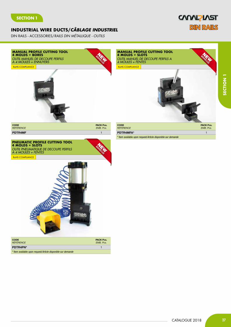
PDtR4mF 1
CODERÉFÉRENCE
PACK Pcs.EMB. Pcs.
PDtR4mFA* 1
* Item available upon request/Article disponible sur demande
CODERÉFÉRENCE
PACK Pcs.EMB. Pcs.
PDtR4Pn* 1
* Item available upon request/Article disponible sur demande
ManUaL ProfiLe cUttinG tooL4 MoLdS + BoreSOUTIL MANUEL DE DECOUPE PERFILs A 4 MOULEs + ENNUyERsRoHS cOmpLIaNcE
ManUaL ProfiLe cUttinG tooL 4 MoLdS + SLotSOUTIL MANUEL DE DECOUPE PERFILs A 4 MOULEs + FENTEsRoHS cOmpLIaNcE
PneUMatic ProfiLe cUttinG tooL 4 MoLdS + SLotSOUTIL PNEUMATIQUE DE DECOUPE PERFILsA 4 MOULEs + FENTEsRoHS cOmpLIaNcE
DIN RAILS - ACCESSORIES/RaiLS DiN MétaLLiQUE - OUtiLS
DIN RAILS
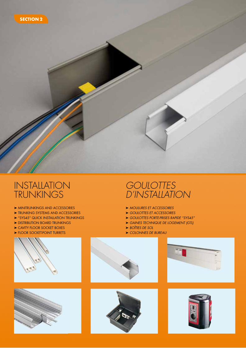
INSTALLATION TRUNKINGS
GOULOTTES D’INSTALLATION
Section 2
➤ MINITRUNKINGS AND ACCESSORIES➤ TRUNKING SYSTEMS AND ACCESSORIES➤ “SYS45” QUICK INSTALLATION TRUNKINGS➤ DISTRIbUTION bOARD TRUNKINGS➤ CAvITY fLOOR SOCKET bOxES➤ fLOOR SOCKET-pOINT TURRETS
➤ MOULURES Et accESSOiRES➤ GOULOttES Et accESSOiRES➤ GOULOttES pORtE-pRiSES RapiDE “SYS45”➤ GaiNES tEcHNiQUE DE LOGEMENt (GtL) ➤ BOÎtiES DE SOL ➤ cOLONNES DE BUREaU

29CATALOGUE 2018
INSTALLATION TRUNKINGS/GOULOTTES D’INSTALLATION
SecT
ION
2
SecTION 2
MINITRUNKINGS AND ACCESSORIES/MOULURES Et accESSOiRES
MinitrUnKinGS WitH HinGed cover and adHeSive BaSe WHite coLoUr - LenGtH 2 mMOULUREs AVEC FOND AUTO-ADHésIF COULEUR BLANCLONGUEUR 2 m
SElF-EXTINGuISHING RIGID PVC ClASS 1, ul94-V0
oUter BendANGLE EXTERIEUR
inner BendANGLE INTERIEUR
cover joint JOINT DE JONCTION
CODERÉFÉRENCE
DimEnSiOnS (b x h)diMENsioNs (b x h)
PACK mEMB. m
G21bEU 10x10 240
G41bEU 20x10 120
G20bEU 15x18 120
G44bEU 25x20 60
G45bEU 40x20x2sc 42
G46bEU 60x20x3sc 28
CODERÉFÉRENCE
DimEnSiOnS (b x h)diMENsioNs (b x h)
PACK mEMB. m
mA117 12,5x7,5 240
mA211 10x10 240
mA215 15x10 96
mA221 20x10 120
mA312 12,5x12,5 160
CODERÉFÉRENCE
FOR tRUnKinGPouR GouLottE
PACK Pcs.EMB. Pcs.
mini41EbEU 20x10 40
mini30EbEU 30x10 40
mini40EbEU 40x10 40
mini11EbEU 16x16 40
mini21EbEU 25x16 40
mini31EbEU 40x16 40
mini61EbEU 60x16 40
mini44EbEU 25x20 20
Gt248EbEU 40x20/40 10
Gt244EbEU 60x20/40 10
CODERÉFÉRENCE
FOR tRUnKinGPouR GouLottE
PACK Pcs.EMB. Pcs.
mini41ibEU 20x10 40
mini30ibEU 30x10 40
mini40ibEU 40x10 40
mini11ibEU 16x16 40
mini21ibEU 25x16 40
mini31ibEU 40x16 40
mini61ibEU 60x16 40
mini44ibEU 25x20 20
Gt248ibEU 40x20/40 10
Gt244ibEU 60x20/40 10
CODERÉFÉRENCE
FOR tRUnKinGPouR GouLottE
PACK Pcs.EMB. Pcs.
mini41GbEU 20x10 40
mini30GbEU 30x10 40
mini40GbEU 40x10 40
mini11GbEU 16x16 40
mini21GbEU 25x16 40
mini31GbEU 40x16 40
mini61GbEU 60x16 40
mini44GbEU 25x20 20
Gt248GbEU 40x20/40 20
Gt244GbEU 60x20/40 20
CODERÉFÉRENCE
DimEnSiOnS (b x h)diMENsioNs (b x h)
PACK mEMB. m
mS201bEU 20x10 120
mS301bEU 30x10 90
mS4010bEU 40x10x2sc 68
bS11bEU 16x16 96
bS21bEU 25x16 72
bS31bEU 40x16x2sc 54
bS61bEU 60x16x3sc 36
MinitrUnKinG WitH SnaP-on cover WHite coLoUr - LenGtH 2 mMOULUREs AVEC COUVERCLE à ENCLIPsAGE COULEUR BLANC - LONGUEUR 2 m
SElF-EXTINGuISHING RIGID PVC ClASS 1, ul94-V0
MinitrUnKinGS WitH WraPPinG cover WHite coLoUr LenGtH 2 mMOULUREs AVEC COUVERCLE RECOUVRANT COULEUR BLANCLONGUEUR 2 m
SElF-EXTINGuISHING RIGID PVC ClASS 1, ul94-V0
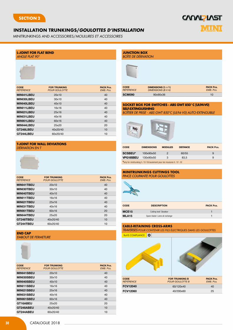
30
INSTALLATION TRUNKINGS/GOULOTTES D’INSTALLATION
CATALOGUE 2018
SecTION 2
MINITRUNKINGS AND ACCESSORIES/MOULURES Et accESSOiRES
L-joint for fLat BendANGLE PLAT 90°
t-joint for WaLL deviationSDéRIVATION EN T
end caPEMBOUT DE FERMETURE
CODERÉFÉRENCE
FOR tRUnKinGPouR GouLottE
PACK Pcs.EMB. Pcs.
mini41lbEU 20x10 40
mini30lbEU 30x10 40
mini40lbEU 40x10 40
mini11lbEU 16x16 40
mini21lbEU 25x16 40
mini31lbEU 40x16 40
mini61lbEU 60x16 40
mini44lbEU 25x20 20
Gt248lbEU 40x20/40 10
Gt244lbEU 60x20/40 10
CODERÉFÉRENCE
FOR tRUnKinGPouR GouLottE
PACK Pcs.EMB. Pcs.
mini41SbEU 20x10 40
mini30SbEU 30x10 40
mini40SbEU 40x10 40
mini11SbEU 16x16 40
mini21SbEU 25x16 40
mini31SbEU 40x16 40
mini61SbEU 60x16 40
Gt16AbEU 25x20 20
Gt248AbEU 40x20/40 10
Gt244AbEU 60x20/40 10
CODERÉFÉRENCE
FOR tRUnKinGPouR GouLottE
PACK Pcs.EMB. Pcs.
mini41tbEU 20x10 40
mini30tbEU 30x10 40
mini40tbEU 40x10 40
mini11tbEU 16x16 40
mini21tbEU 25x16 40
mini31tbEU 40x16 40
mini61tbEU 60x16 20
mini44tbEU 25x20 20
Gt248tbEU 40x20/40 10
Gt244tbEU 60x20/40 10
MinitrUnKinGS cUttinGS tooLPINCE COUPANTE POUR GOULOTTEs
CODE DESCRiPtiOn PACK Pcs.
mCE15 Cutting tool/ Secateur 1
mlA15 Spare blade/ Lame de rechange 1
SocKet BoX for SWitcHeS - aBS GWt 850°c (UL94-v0) SeLf-eXtinGUiSHinGBOîTIER DE PRIsE - ABs GWT 850°C (UL94-V0) AUTO-EXTINGUIBLE
CODE DimEnSiOnS mODUlES DiStAnCE PACK Pcs.
SCSbEU* 100x90x50 2 60/55 9
VPG18SbEU 130x90x50 3 83,5 9
*only for minitrunking h. 10-16/seulement pour les moulures h. 10 -16
jUnction BoXBOîTE DE DéRIVATION
CODERÉFÉRENCE
DimEnSiOnS (b x h)diMENsioNs (B x h)
PACK Pcs.EMB. Pcs.
SCm090 90x90x36 10
CODERÉFÉRENCE
FOR tRUnKinG bPouR GouLottE B
PACK Pcs.EMB. Pcs.
FCV12040 60/120x40 40
FCV12060 40/200x60 25
caBLe-retaininG croSS-arMSTRAVERsEs pour contenir Les fiLs éLectriques dAns Les gouLottes
RoHS cOmpLIaNcE
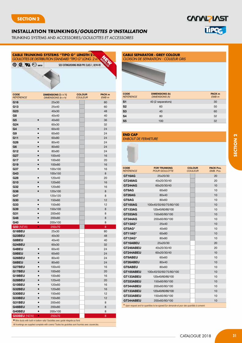
31CATALOGUE 2018
INSTALLATION TRUNKINGS/GOULOTTES D’INSTALLATION
SecT
ION
2
SecTION 2
TRUNKING SYSTEMS AND ACCESSORIES/GOULOttES Et accESSOiRES
caBLe SeParator - Grey coLoUrCLOIsON DE sEPARATION - COULEUR GRIs
CODERÉFÉRENCE
DimEnSiOnS (h)diMENsioNs (h)
PACK mEMB m
S1 40 (2 separators) 30
S2 60 50
S3 40 60
S4 80 32
S5 100 32
end caPEMBOUT DE FERMETURE
CODERÉFÉRENCE
FOR tRUnKinGPouR GouLottE
COlOURCouLEuR
PACK Pcs.EMB. Pcs.
Gt16AG 25x20/30 20
Gt248AG 40x20/30/40 20
Gt244AG 60x20/30/40 10
Gt9AG 60x60 10
Gt26AG 80x40 10
Gt6AG 80x60 10
Gt100AG 100x40/50/60/75/80/100 10
Gt133AG 120x40/60/80/100 10
Gt333AG 150x60/80/100 10
Gt344AG 200x60/80/100 10
Gt13AG* 25x40 10
Gt5AG* 40x60 10
Gt11AG* 60x80 10
Gt12AG* 80x80 10
Gt16AbEU 25x20/30 20
Gt248AbEU 40x20/30/40 20
Gt244AbEU 60x20/30/40 10
Gt9AbEU 60x60 10
Gt26AbEU 80x40 10
Gt6AbEU 80x60 10
Gt100AbEU 100x40/50/60/75/80/100 10
Gt133AbEU 120x40/60/80/100 10
Gt333AbEU 150x60/80/100 10
Gt344AbEU 200x60/80/100 10
Gt133AbEU 120x40/60/80/100 10
Gt333AbEU 150x60/80/100 10
Gt344AbEU 200x60/80/100 10
* Upon request and for quantities to be agreed/Sur demande et pour des quantités à convenir.
caBLe trUnKinG SySteMS “tiPo G” LenGtH 2 mGOULOTTEs DE DIsTRIBUTION sTANDARD “TIPO G” LONG. 2 m
SElF-EXTINGuISHING RIGID PVC ClASS 1, ul94-V0
CODERÉFÉRENCE
DimEnSiOnS (b x h)diMENsioNs (b x h)
COlOURCouLEuR
PACK mEMB m
G16 25x30 80
G13 25x40 60
G23 40x30 48
G8 40x40 40
G5 • 40x60 36
G24 60x30 32
G4 • 60x40 24
G9 • 60x60 24
G11 • 60x80 24
G26 • 80x40 24
G6 • 80x60 24
G12 • 80x80 24
G27 • 100x40 16
G17 • 100x60 20
G19 • 100x80 16
G37 • 100x100 16
G43 100x150 8
G28 • 120x40 20
G10 • 120x60 16
G32 • 120x80 16
G38 • 120x100 8
G47 120x120 8
G30 • 150x60 12
G33 • 150x80 12
G39 • 150x100 8
G31 • 200x60 8
G48 • 200x80 8
G40 • 200x100 8
G50 (NEW) • 250x70 8
G16bEU 25x30 80
G23bEU 40x30 48
G8bEU 40x40 40
G24bEU 60x30 32
G4bEU • 60x40 24
G9bEU • 60x60 24
G26bEU • 80x40 24
G6bEU • 80x60 24
G27bEU • 100x40 16
G17bEU • 100x60 20
G19bEU • 100x80 16
G28bEU • 120x40 20
G10bEU • 120x60 16
G32bEU • 120x80 16
G30bEU • 150x60 12
G33bEU • 150x80 12
G31bEU • 200x60 8
G48bEU • 200x80 8
G40bEU • 200x100 8
G50bEU (NEW) • 250x70 8
• Wire ducts with built-in bottom rails/ Goulottes avec guide integrée au fond
All trunkings are supplied complete with covers/ Toutes les goulottes sont fournies avec couvercles.
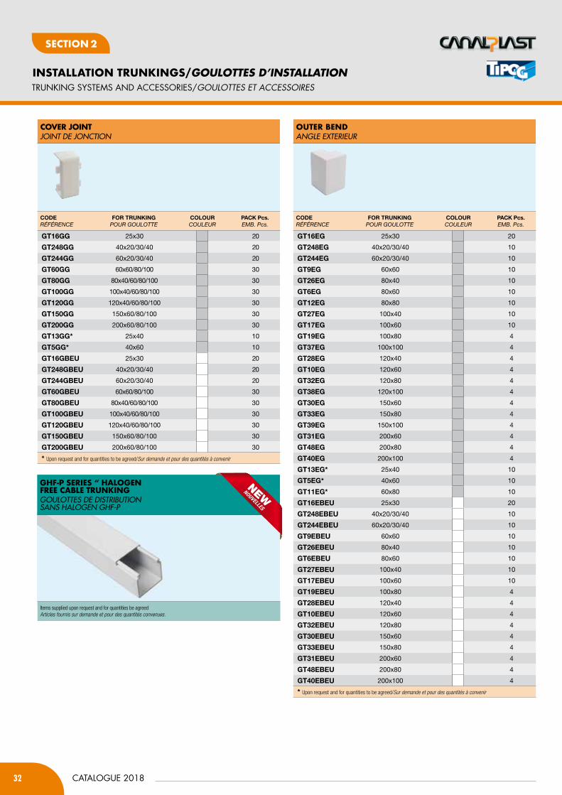
32
INSTALLATION TRUNKINGS/GOULOTTES D’INSTALLATION
CATALOGUE 2018
SecTION 2
oUter BendANGLE EXTERIEUR
TRUNKING SYSTEMS AND ACCESSORIES/GOULOttES Et accESSOiRES
cover joint JOINT DE JONCTION
CODERÉFÉRENCE
FOR tRUnKinGPouR GouLottE
COlOURCouLEuR
PACK Pcs.EMB. Pcs.
Gt16GG 25x30 20
Gt248GG 40x20/30/40 20
Gt244GG 60x20/30/40 20
Gt60GG 60x60/80/100 30
Gt80GG 80x40/60/80/100 30
Gt100GG 100x40/60/80/100 30
Gt120GG 120x40/60/80/100 30
Gt150GG 150x60/80/100 30
Gt200GG 200x60/80/100 30
Gt13GG* 25x40 10
Gt5GG* 40x60 10
Gt16GbEU 25x30 20
Gt248GbEU 40x20/30/40 20
Gt244GbEU 60x20/30/40 20
Gt60GbEU 60x60/80/100 30
Gt80GbEU 80x40/60/80/100 30
Gt100GbEU 100x40/60/80/100 30
Gt120GbEU 120x40/60/80/100 30
Gt150GbEU 150x60/80/100 30
Gt200GbEU 200x60/80/100 30
* Upon request and for quantities to be agreed/Sur demande et pour des quantités à convenir
CODERÉFÉRENCE
FOR tRUnKinGPouR GouLottE
COlOURCouLEuR
PACK Pcs.EMB. Pcs.
Gt16EG 25x30 20
Gt248EG 40x20/30/40 10
Gt244EG 60x20/30/40 10
Gt9EG 60x60 10
Gt26EG 80x40 10
Gt6EG 80x60 10
Gt12EG 80x80 10
Gt27EG 100x40 10
Gt17EG 100x60 10
Gt19EG 100x80 4
Gt37EG 100x100 4
Gt28EG 120x40 4
Gt10EG 120x60 4
Gt32EG 120x80 4
Gt38EG 120x100 4
Gt30EG 150x60 4
Gt33EG 150x80 4
Gt39EG 150x100 4
Gt31EG 200x60 4
Gt48EG 200x80 4
Gt40EG 200x100 4
Gt13EG* 25x40 10
Gt5EG* 40x60 10
Gt11EG* 60x80 10
Gt16EbEU 25x30 20
Gt248EbEU 40x20/30/40 10
Gt244EbEU 60x20/30/40 10
Gt9EbEU 60x60 10
Gt26EbEU 80x40 10
Gt6EbEU 80x60 10
Gt27EbEU 100x40 10
Gt17EbEU 100x60 10
Gt19EbEU 100x80 4
Gt28EbEU 120x40 4
Gt10EbEU 120x60 4
Gt32EbEU 120x80 4
Gt30EbEU 150x60 4
Gt33EbEU 150x80 4
Gt31EbEU 200x60 4
Gt48EbEU 200x80 4
Gt40EbEU 200x100 4
* Upon request and for quantities to be agreed/Sur demande et pour des quantités à convenir
GHf-P SerieS “ HaLoGen free caBLe trUnKinGGOULOTTEs DE DIsTRIBUTION sANs HALOGEN GHF-P
Items supplied upon request and for quantities be agreedArticles fournis sur demande et pour des quantités convenues.
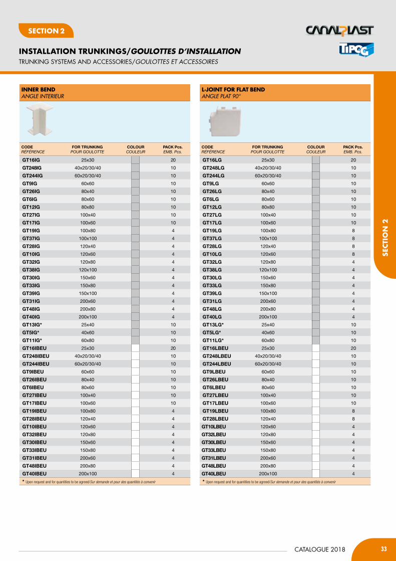
33CATALOGUE 2018
INSTALLATION TRUNKINGS/GOULOTTES D’INSTALLATION
SecT
ION
2
SecTION 2
TRUNKING SYSTEMS AND ACCESSORIES/GOULOttES Et accESSOiRES
L-joint for fLat BendANGLE PLAT 90°
inner BendANGLE INTERIEUR
CODERÉFÉRENCE
FOR tRUnKinGPouR GouLottE
COlOURCouLEuR
PACK Pcs.EMB. Pcs.
Gt16iG 25x30 20
Gt248iG 40x20/30/40 10
Gt244iG 60x20/30/40 10
Gt9iG 60x60 10
Gt26iG 80x40 10
Gt6iG 80x60 10
Gt12iG 80x80 10
Gt27iG 100x40 10
Gt17iG 100x60 10
Gt19iG 100x80 4
Gt37iG 100x100 4
Gt28iG 120x40 4
Gt10iG 120x60 4
Gt32iG 120x80 4
Gt38iG 120x100 4
Gt30iG 150x60 4
Gt33iG 150x80 4
Gt39iG 150x100 4
Gt31iG 200x60 4
Gt48iG 200x80 4
Gt40iG 200x100 4
Gt13iG* 25x40 10
Gt5iG* 40x60 10
Gt11iG* 60x80 10
Gt16ibEU 25x30 20
Gt248ibEU 40x20/30/40 10
Gt244ibEU 60x20/30/40 10
Gt9ibEU 60x60 10
Gt26ibEU 80x40 10
Gt6ibEU 80x60 10
Gt27ibEU 100x40 10
Gt17ibEU 100x60 10
Gt19ibEU 100x80 4
Gt28ibEU 120x40 4
Gt10ibEU 120x60 4
Gt32ibEU 120x80 4
Gt30ibEU 150x60 4
Gt33ibEU 150x80 4
Gt31ibEU 200x60 4
Gt48ibEU 200x80 4
Gt40ibEU 200x100 4
* Upon request and for quantities to be agreed/Sur demande et pour des quantités à convenir
CODERÉFÉRENCE
FOR tRUnKinGPouR GouLottE
COlOURCouLEuR
PACK Pcs.EMB. Pcs.
Gt16lG 25x30 20
Gt248lG 40x20/30/40 10
Gt244lG 60x20/30/40 10
Gt9lG 60x60 10
Gt26lG 80x40 10
Gt6lG 80x60 10
Gt12lG 80x80 10
Gt27lG 100x40 10
Gt17lG 100x60 10
Gt19lG 100x80 8
Gt37lG 100x100 8
Gt28lG 120x40 8
Gt10lG 120x60 8
Gt32lG 120x80 4
Gt38lG 120x100 4
Gt30lG 150x60 4
Gt33lG 150x80 4
Gt39lG 150x100 4
Gt31lG 200x60 4
Gt48lG 200x80 4
Gt40lG 200x100 4
Gt13lG* 25x40 10
Gt5lG* 40x60 10
Gt11lG* 60x80 10
Gt16lbEU 25x30 20
Gt248lbEU 40x20/30/40 10
Gt244lbEU 60x20/30/40 10
Gt9lbEU 60x60 10
Gt26lbEU 80x40 10
Gt6lbEU 80x60 10
Gt27lbEU 100x40 10
Gt17lbEU 100x60 10
Gt19lbEU 100x80 8
Gt28lbEU 120x40 8
Gt10lbEU 120x60 4
Gt32lbEU 120x80 4
Gt30lbEU 150x60 4
Gt33lbEU 150x80 4
Gt31lbEU 200x60 4
Gt48lbEU 200x80 4
Gt40lbEU 200x100 4
* Upon request and for quantities to be agreed/Sur demande et pour des quantités à convenir
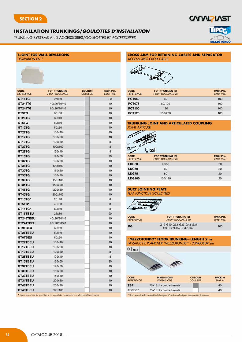
34
INSTALLATION TRUNKINGS/GOULOTTES D’INSTALLATION
CATALOGUE 2018
SecTION 2
t-joint for WaLL deviationSDéRIVATION EN T
croSS arM for retaininG caBLeS and SeParatorACCEssOIREs CROIX CÂBLE
trUnKinG joint and articULated coUPLinGJOINT ARTICULE
dUct jointinG PLatePLAT JONCTION GOULOTTEs
CODERÉFÉRENCE
FOR tRUnKinGPouR GouLottE
COlOURCouLEuR
PACK Pcs.EMB. Pcs.
Gt16tG 25x30 20
Gt248tG 40x20/30/40 10
Gt244tG 60x20/30/40 10
Gt9tG 60x60 10
Gt26tG 80x40 10
Gt6tG 80x60 10
Gt12tG 80x80 10
Gt27tG 100x40 10
Gt17tG 100x60 10
Gt19tG 100x80 8
Gt37tG 100x100 8
Gt28tG 120x40 8
Gt10tG 120x60 20
Gt32tG 120x80 10
Gt38tG 120x100 10
Gt30tG 150x60 10
Gt33tG 150x80 10
Gt39tG 150x100 10
Gt31tG 200x60 10
Gt48tG 200x80 10
Gt40tG 200x100 10
Gt13tG* 25x40 8
Gt5tG* 40x60 8
Gt11tG* 60x80 8
Gt16tbEU 25x30 20
Gt248tbEU 40x20/30/40 10
Gt244tbEU 60x20/30/40 10
Gt9tbEU 60x60 10
Gt26tbEU 80x40 10
Gt6tbEU 80x60 10
Gt27tbEU 100x40 10
Gt17tbEU 100x60 10
Gt19tbEU 100x80 8
Gt28tbEU 120x40 8
Gt10tbEU 120x60 20
Gt32tbEU 120x80 10
Gt30tbEU 150x60 10
Gt33tbEU 150x80 10
Gt31tbEU 200x60 10
Gt48tbEU 200x80 10
Gt40tbEU 200x100 10
* Upon request and for quantities to be agreed/Sur demande et pour des quantités à convenir
CODERÉFÉRENCE
FOR tRUnKinG (b) PouR GouLottE (B)
PACK Pcs.EMB. Pcs.
PCt050 60 100
PCt075 80/100 100
PCt100 120 100
PCt125 150/200 100
CODERÉFÉRENCE
FOR tRUnKinG (b) PouR GouLottE (B)
PACK Pcs.EMB. Pcs.
lDG50 40/50 20
lDG60 60 20
lDG75 80 20
lDG100 100/120 20
CODERÉFÉRENCE
FOR tRUnKinG (b) PouR GouLottE (B)
PACK Pcs.EMB. Pcs.
PG G12-G19-G32-G33-G48-G37 G38-G39-G40-G47-G43
100
TRUNKING SYSTEMS AND ACCESSORIES/GOULOttES Et accESSOiRES
CODERÉFÉRENCE
DimEnSiOnSdiMENsioNs
COlOURCouLEuR
PACK mEMB. m
ZbF 75x18x4 compartiments 40
ZbFbE* 75x18x4 compartiments 40
* Upon request and for quantities to be agreed/Sur demande et pour des quantités à convenir
“MeZZotondo” fLoor trUnKinG - LenGtH 2 mPAssAGE DE PLANCHER “MEZZOTONDO” - LONGUEUR 2m
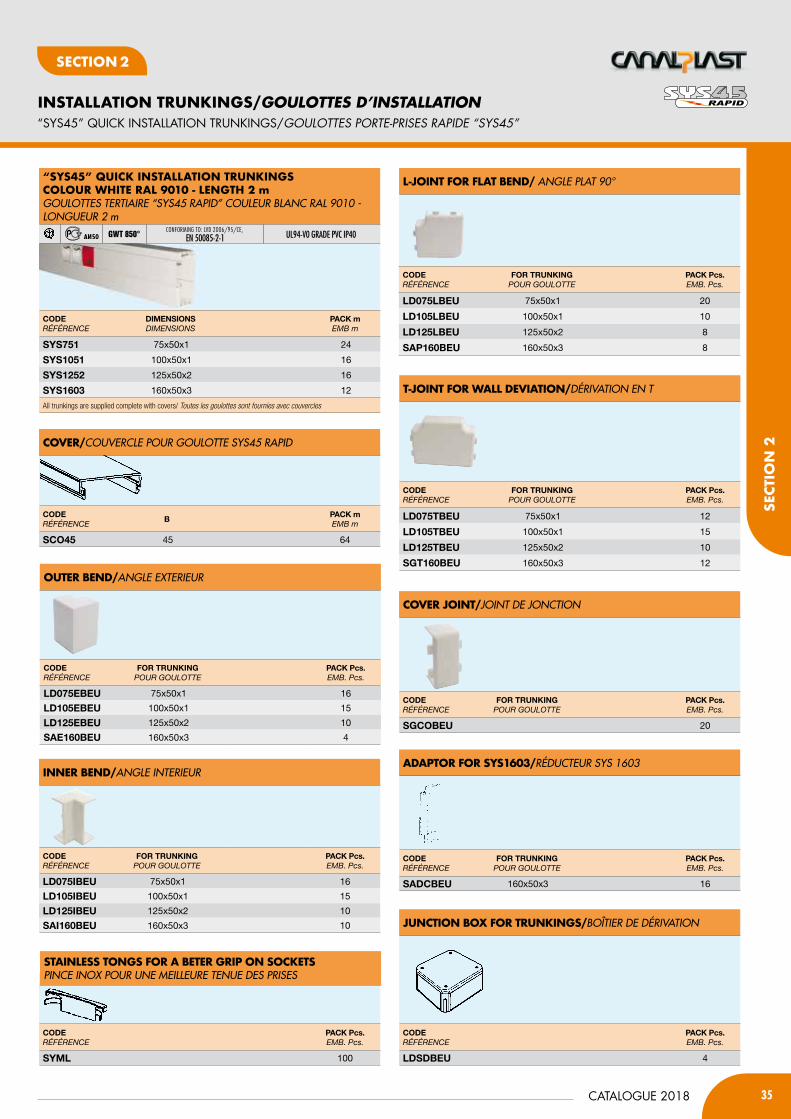
35CATALOGUE 2018
INSTALLATION TRUNKINGS/GOULOTTES D’INSTALLATION
SecT
ION
2
SecTION 2
“SYS45” QUICK INSTALLATION TRUNKINGS/GOULOttES pORtE-pRiSES RapiDE “SYS45”
oUter Bend/ANGLE EXTERIEUR
L-joint for fLat Bend/ ANGLE PLAT 90°
t-joint for WaLL deviation/DéRIVATION EN T
inner Bend/ANGLE INTERIEUR
CODERÉFÉRENCE
FOR tRUnKinGPouR GouLottE
PACK Pcs.EMB. Pcs.
lD075EbEU 75x50x1 16
lD105EbEU 100x50x1 15
lD125EbEU 125x50x2 10
SAE160bEU 160x50x3 4
CODERÉFÉRENCE
bPACK mEMB m
SCO45 45 64
CODERÉFÉRENCE
FOR tRUnKinGPouR GouLottE
PACK Pcs.EMB. Pcs.
lD075lbEU 75x50x1 20
lD105lbEU 100x50x1 10
lD125lbEU 125x50x2 8
SAP160bEU 160x50x3 8
CODERÉFÉRENCE
FOR tRUnKinGPouR GouLottE
PACK Pcs.EMB. Pcs.
lD075tbEU 75x50x1 12
lD105tbEU 100x50x1 15
lD125tbEU 125x50x2 10
SGt160bEU 160x50x3 12
CODERÉFÉRENCE
FOR tRUnKinGPouR GouLottE
PACK Pcs.EMB. Pcs.
lD075ibEU 75x50x1 16
lD105ibEU 100x50x1 15
lD125ibEU 125x50x2 10
SAi160bEU 160x50x3 10
cover/COUVERCLE POUR GOULOTTE sys45 RAPID
cover joint/JOINT DE JONCTION
adaPtor for SyS1603/RéDUCTEUR sys 1603
jUnction BoX for trUnKinGS/BOîTIER DE DéRIVATION
StainLeSS tonGS for a Beter GriP on SocKetSPINCE INOX POUR UNE MEILLEURE TENUE DEs PRIsEs
CODERÉFÉRENCE
FOR tRUnKinGPouR GouLottE
PACK Pcs.EMB. Pcs.
SGCObEU 20
CODERÉFÉRENCE
FOR tRUnKinGPouR GouLottE
PACK Pcs.EMB. Pcs.
SADCbEU 160x50x3 16
CODERÉFÉRENCE
PACK Pcs.EMB. Pcs.
lDSDbEU 4
CODERÉFÉRENCE
PACK Pcs.EMB. Pcs.
Syml 100
CODERÉFÉRENCE
DimEnSiOnSdiMENsioNs
PACK mEMB m
SyS751 75x50x1 24
SyS1051 100x50x1 16
SyS1252 125x50x2 16
SyS1603 160x50x3 12
All trunkings are supplied complete with covers/ Toutes les goulottes sont fournies avec couvercles
“SyS45” QUicK inStaLLation trUnKinGScoLoUr WHite raL 9010 - LenGtH 2 mGOULOTTEs TERTIAIRE “sys45 RAPID” COULEUR BLANC RAL 9010 - LONGUEUR 2 m
GWT 850°CONFORMING TO: LVD 2006/95/CE,
EN 50085-2-1 ul94-V0 GRADE PVC IP40
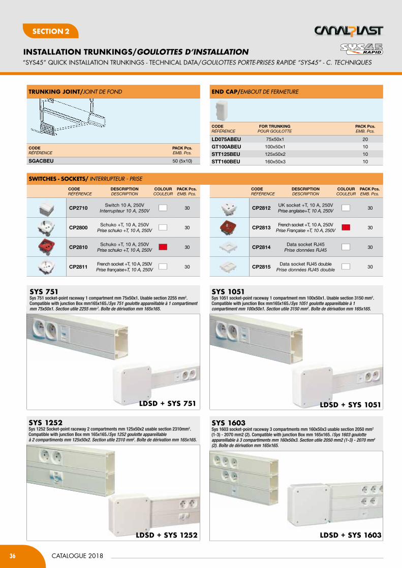
36
INSTALLATION TRUNKINGS/GOULOTTES D’INSTALLATION
CATALOGUE 2018
SecTION 2
SyS 751Sys 751 socket-point raceway 1 compartment mm 75x50x1. Usable section 2255 mm2.Compatible with junction Box mm165x165./Sys 751 goulotte appareillable à 1 compartiment mm 75x50x1. Section utile 2255 mm 2. Boîte de dérivation mm 165x165.
“SYS45” QUICK INSTALLATION TRUNKINGS - TECHNICAL DATA/GOULOttES pORtE-pRiSES RapiDE “SYS45” - c. tEcHNiQUES
LdSd + SyS 751
LdSd + SyS 1603
LdSd + SyS 1051
SyS 1051Sys 1051 socket-point raceway 1 compartment mm 100x50x1. Usable section 3150 mm2.Compatible with junction Box mm165x165./Sys 1051 goulotte appareillable à 1 compartiment mm 100x50x1. Section utile 3150 mm2. Boîte de dérivation mm 165x165.
LdSd + SyS 1252
SyS 1252Sys 1252 Socket-point raceway 2 compartments mm 125x50x2 usable section 2310mm2.Compatible with junction Box mm 165x165./Sys 1252 goulotte appareillable à 2 compartiments mm 125x50x2. Section utile 2310 mm2. Boîte de dérivation mm 165x165.
SyS 1603Sys 1603 socket-point raceway 3 compartments mm 160x50x3 usable section 2050 mm2 (1-3) - 2070 mm2 (2). Compatible with junction Box mm 165x165. /Sys 1603 goulotte appareillable à 3 compartiments mm 160x50x3. Section utile 2050 mm2 (1-3) - 2070 mm2 (2). Boîte de dérivation mm 165x165.
SWitcHeS - SocKetS/ INTERRUPTEUR - PRIsE
CODERÉFÉRENCE
DESCRiPtiOndEsCRiPtioN
COlOURCouLEuR
PACK Pcs.EMB. Pcs.
CP2710 Switch 10 A, 250Vinterrupteur 10 A, 250V
30
CP2800 Schuko +T, 10 A, 250VPrise schuko +t, 10 A, 250V
30
CP2810 Schuko +T, 10 A, 250VPrise schuko +t, 10 A, 250V
30
CP2811 French socket +T, 10 A, 250VPrise française+t, 10 A, 250V
30
CODERÉFÉRENCE
DESCRiPtiOndEsCRiPtioN
COlOURCouLEuR
PACK Pcs.EMB. Pcs.
CP2812 UK socket +T, 10 A, 250VPrise anglaise+t, 10 A, 250V
30
CP2813 French socket +T, 10 A, 250VPrise Française +t, 10 A, 250V
30
CP2814 Data socket RJ45Prise données RJ45
30
CP2815 Data socket RJ45 doublePrise données RJ45 double
30
trUnKinG joint/JOINT DE FOND end caP/EMBOUT DE FERMETURE
CODERÉFÉRENCE
PACK Pcs.EMB. Pcs.
SGACbEU 50 (5x10)
CODERÉFÉRENCE
FOR tRUnKinGPouR GouLottE
PACK Pcs.EMB. Pcs.
lD075AbEU 75x50x1 20
Gt100AbEU 100x50x1 10
Stt125bEU 125x50x2 10
Stt160bEU 160x50x3 10

37CATALOGUE 2018
INSTALLATION TRUNKINGS/GOULOTTES D’INSTALLATION
SecT
ION
2
SecTION 2
inStaLLation trUnKinGS, incLUdinG cover reMov-aBLe By tooL - LenGHt 2 mGOULOTTEs D’INsTALLATION COMPLèTE AVEC COUVERCLE AMOVIBLE AVEC L’OUTIL - LONGUEUR 2 m
SElF-EXTINGuISHING RIGID PVC ClASS 1, ul94-V0
caBLe trUnKinGS WitH raiLS on tHe BottoM - LenGHt 2 mGOULOTTEs AVEC GUIDE INTEGRéE AU FOND - LONGUEUR 2 m
SElF-EXTINGuISHING RIGID PVC ClASS 1, ul94-V0
CODERÉFÉRENCE
DimEnSiOnS (b x h)diMENsioNs (b x h)
PACK mEMB m
lDC022bEU 25x25 80
lDC032bEU 37,5x25 52
lDC033bEU 37,5x37,5 36
lDC053bEU • 50x37,5 28
lDC055bEU • 50x50 24
lDC075bEU • 75x50 20
lDC105bEU • 100x50 16
lDC125bEU • 125x50 20
lDC155bEU • 150x50 12
lDC205bEU • 200x50 12
lDC077bEU • 75x75 20
lDC107bEU • 100x75 16
lDC127bEU • 125x75 12
lDC157bEU • 150x75 8
lDC207bEU • 200x75 8
• Wire ducts with built-in bottom rails/ Goulottes avec guide integrée au fond
All trunkings are supplied complete with covers/ Toutes les goulottes sont fournies avec couvercles.
CODERÉFÉRENCE
DimEnSiOnS (b x h)diMENsioNs (b x h)
PACK mEMB m
lD100CAbEU 100x50 24
lD150CAbEU 150x50 12
lD200CAbEU 200x50 12
CODERÉFÉRENCE
DimEnSiOnS (b)diMENsioNs (b)
PACK mEMB m
lD050CObEU 50 96
lD100CObEU 100 48
lD150CObEU 150 16
lD200CObEU 200 16
cover/COUVERCLE POUR GOULOTTE
oUter Bend/ANGLE EXTERIEUR
CODERÉFÉRENCE
FOR tRUnKinGPouR GouLottE
PACK Pcs.EMB. Pcs.
lD022EbEU 25x25 25
lD032EbEU 37,5x25 20
lD033EbEU 37,5x37,5 20
lD053EbEU 50x37,5 16
lD055EbEU 50x50 16
lD075EbEU 75x50 16
lD105EbEU 100x50 15
lD125EbEU 125x50 10
lD155EbEU 150x50 4
lD205EbEU 200x50 4
lD077EbEU 75x75 16
lD107EbEU 100x75 4
lD127EbEU 125x75 4
lD157EbEU 150x75 4
lD207EbEU 200x75 4
inner Bend/ANGLE INTERIEUR
PLate for Mod. 503/504 and 506 for USe Lineadin trUnKinGS 100-150-200 H50PLAQUE POUR MOD. 503-504 ET 506 POUR GOULOTTEs LINEADIN 100-150-200 H. 50
CODERÉFÉRENCE
FOR tRUnKinGPouR GouLottE
PACK Pcs.EMB. Pcs.
lD022ibEU 25x25 25
lD032ibEU 37,5x25 20
lD033ibEU 37,5x37,5 20
lD053ibEU 50x37,5 12
lD055ibEU 50x50 12
lD075ibEU 75x50 16
lD105ibEU 100x50 15
lD125ibEU 125x50 10
lD155ibEU 150x50 10
lD205ibEU 200x50 4
lD077ibEU 75x75 15
lD107ibEU 100x75 4
lD127ibEU 125x75 4
lD157ibEU 150x75 4
lD207ibEU 200x75 4
CODERÉFÉRENCE
PACK Pcs.EMB. Pcs.
lDm504bEU 25
lDm506bEU 20
DISTRIbUTION bOARD TRUNKINGS/GaiNES tEcHNiQUE DE LOGEMENt (GtL)

38
INSTALLATION TRUNKINGS/GOULOTTES D’INSTALLATION
CATALOGUE 2018
SecTION 2
LateraL SeParator / CLOIsON DE sEPARATION
croSS arM for caBLeS retention / CLIP DE MAINTIEN
centraL SeParator - Grey coLoUrséPARATEUR CENTRAL - COULEUR GRIs
CODERÉFÉRENCE
DimEnSiOnS hdiMENsioNs h
PACK mEMB m
lDS50 50 50lDS75 75 50
CODERÉFÉRENCE
DimEnSiOnS bdiMENsioNs b
PACK mEMB m
lDt50 50 500 (5X100)
lDt75 75 300 (3X100)
lDt100 100 200(2X100)
lDt125 125 150 (2X75)
lDt150 150 50
lDt200 200 50
CODERÉFÉRENCE
DimEnSiOnS hdiMENsioNs h
PACK mEMB m
lDSC50 50 50lDSC75 75 25
end caP/ EMBOUT DE FERMETURE
cover joint/JOINT DE JONCTION
CODERÉFÉRENCE
FOR tRUnKinGPouR GouLottE
PACK Pcs.EMB. Pcs.
lD022GbEU 25x25 25
lD032GbEU 37,5x25 20
lD033GbEU 37,5x37,5 20
lD053tbEU 50x37,5 12
lD055tbEU 50x50 12
lD075tbEU 75x50 12
lD105GbEU 100x50 30
lD125GbEU 125x50 30
lD155GbEU 150x50 30
lD205GbEU 200x50 30
lD077GbEU* 75x75 20
lD107GbEU 100x75 30
lD127GbEU 125x75 30
lD157GbEU 150x75 30
lD207GbEU 200x75 30
*Available on request and for quantities to be agreed/Disponible sur demande et pour des quantités à convenir
L-joint for fLat Bend/ ANGLE PLAT 90°
t-joint for WaLL deviationS / DéRIVATION EN T
CODERÉFÉRENCE
FOR tRUnKinGPouR GouLottE
PACK Pcs.EMB. Pcs.
lD022lbEU 25x25 25lD032lbEU 37,5x25 20lD033lbEU 37,5x37,5 20lD053lbEU 50x37,5 16lD055lbEU 50x50 16lD075lbEU 75x50 20lD105lbEU 100x50 10lD125lbEU 125x50 8lD155lbEU 150x50 10lD205lbEU 200x50 4lD077lbEU* 75x75 10lD107lbEU* 100x75 4lD127lbEU* 125x75 4lD157lbEU 150x75 4lD207lbEU 200x75 4*Available on request and for quantities to be agreed/Disponible sur demande et pour des quantités à convenir
CODERÉFÉRENCE
FOR tRUnKinGPouR GouLottE
PACK Pcs.EMB. Pcs.
lD022tbEU 25x25 25
lD032tbEU 37,5x25 20
lD033tbEU 37,5x37,5 20
lD053tbEU 50x37,5 12
lD055tbEU 50x50 12
lD075tbEU 75x50 12
lD105tbEU 100x50 15
lD125tbEU 125x50 10
lD155tbEU 150x50 10
lD205tbEU 200x50 8
lD077tbEU 75x75 10
lD107tbEU 100x75 4
lD127tbEU 125x75 4
lD157tbEU 150x75 4
lD207tbEU 200x75 4
CODERÉFÉRENCE
FOR tRUnKinGPouR GouLottE
PACK Pcs.EMB. Pcs.
lD022AbEU 25x25 25lD032AbEU 37,5x25 20lD033AbEU 37,5x37,5 20lD053AbEU 50x37,5 20lD055AbEU 50x50 20lD075AbEU 75x50 20Gt100AbEU 100x50 - 100x75 10lD127AbEU 125x50 - 125x75 10lD155AbEU 150x50 10lD205AbEU 200x50 10lD077AbEU 75x75 10lD157AbEU 150x75 10lD207AbEU 200x75 10
DISTRIbUTION bOARD TRUNKINGS/GaiNES tEcHNiQUE DE LOGEMENt (GtL)

39CATALOGUE 2018
INSTALLATION TRUNKINGS/GOULOTTES D’INSTALLATION
SecT
ION
2
SecTION 2
DISTRIbUTION bOARD TRUNKINGS/GaiNES tEcHNiQUE DE LOGEMENt (GtL)
CODERÉFÉRENCE
DESCRiPtiOndEsCRiPtioN
PACK Pcs.EMB. Pcs.
Kit250
1 trunking length 1250mm L=100 mm1 trunking length 1250mm L=150 mm2 trunkings matching profile 1250 mm1 goulotte long. 1250 mm L=100 mm1 goulotte long. 1250 mm L=150 mm2 profiles de liaison laterale 1250 mm
1
CODERÉFÉRENCE
DESCRiPtiOndEsCRiPtioN
PACK Pcs.EMB. Pcs.
Kit350
1 trunking length 1250mm W=200mm1 trunking length 1250mm W=150mm
2 couplings between two trunkings. 1250mm1 goulotte long. 1250 mm L=200 mm1 goulotte long. 1250 mm L=150 mm2 profiles de liaison laterale 1250 mm
1
CODERÉFÉRENCE
PACK Pcs.EMB. Pcs.
DmA 1/10
CODERÉFÉRENCE
PACK Pcs.EMB. Pcs.
Dm050 10
CODERÉFÉRENCE
DimEnSiOnSdiMENsioNs
PACK Pcs.EMB. Pcs.
DmtR10 100 20
DmtR15 150 20
DmtR20 200 20
CODERÉFÉRENCE
lEnGtH mLoNGuEuR m
PACK mEMB. m
lDS50 1 50
CODERÉFÉRENCE
PACK Pcs.EMB. Pcs.
DmF 100
CODERÉFÉRENCE
DimEnSiOnSdiMENsioNs
PACK Pcs.EMB. Pcs.
Dmt10 100 10
Dmt15 150 10
Dmt20 250 10trUnKinG MatcHinG ProfiLeKIT DE JONCTION LINEAIRE
coUPLinG BetWeen tWo trUnKinGSPROFIL DE LIAIsON LATERALE
end caP/EMBOUT DE FERMETURE
caBLe SeParator/séPARATEUR
caBLe-tie HoLder/FIXE COLLIER
croSS arM for caBLeS and SeParatorS retentionAGRAPHE
diStriBUtion Board trUnKinGS Kit 250 mm KIT GAINEs TECHNIQUE DE LOGEMENT (GTL) 250 mm
diStriBUtion Board trUnKinGS Kit 350 mmKIT GAINEs TECHNIQUE DE LOGEMENT (GTL) 350 mm
caBLe trUnKinG SySteMS “tiPo G” LenGtH 2 mGOULOTTEs DE DIsTRIBUTION sTANDARD “TIPO G” LONG. 2 m
SElF-EXTINGuISHING RIGID PVC ClASS 1, ul94-V0
CODERÉFÉRENCE
DimEnSiOnS (b x h)diMENsioNs (b x h)
COlOURCouLEuR
PACK mEMB m
G50 (NEW) 250x70 8
G50bEU (NEW) 250x70 8Wire ducts with built-in bottom rails. All trunkings are supplied complete with coversGoulottes avec guide integrée au fond. Toutes les goulottes sont fournies avec couvercles.
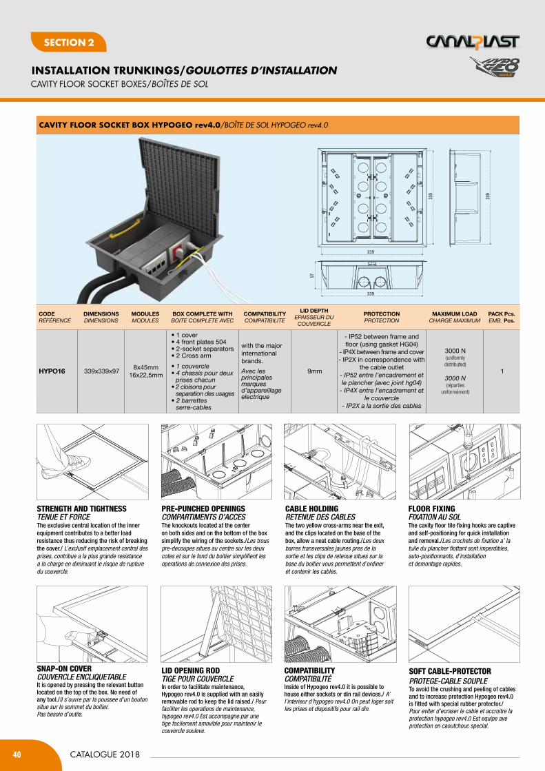
40
INSTALLATION TRUNKINGS/GOULOTTES D’INSTALLATION
CATALOGUE 2018
SecTION 2
CAvITY fLOOR SOCKET bOxES/BOÎtES DE SOL
CODERÉFÉRENCE
DimEnSiOnSdiMENsioNs
mODUlESModuLEs
bOx COmPlEtE WitHBoitE CoMPLEtE AVEC
COmPAtibilityCoMPAtiBiLitE
liD DEPtHEPAissEuR du
CouVERCLE
PROtECtiOnPRotECtioN
mAximUm lOADChARGE MAxiMuM
PACK Pcs.EMB. Pcs.
HyPO16 339x339x978x45mm
16x22,5mm
• 1 cover• 4 front plates 504• 2-socket separators• 2 Cross arm
• 1 couvercle • 4 chassis pour deux prises chacun• 2 cloisons pour separation des usages• 2 barrettes serre-cables
with the major international brands.
Avec les principales marques d’appareillage electrique
9mm
- IP52 between frame and floor (using gasket HG04)
- IP4X between frame and cover- IP2X in correspondence with
the cable outlet- iP52 entre l’encadrement et le plancher (avec joint hg04)
- iP4x entre l’encadrement et le couvercle
- iP2x a la sortie des cables
3000 N(uniformly distributed)
3000 N(réparties
uniformément)
1
cavity fLoor SocKet BoX HyPoGeo rev4.0/BOîTE DE sOL HyPOGEO rev4.0
339
339
339
339
97
PRE-PUNCHED OPENINGSCOMPARTIMENTS D’ACCESThe knockouts located at the center on both sides and on the bottom of the boxsimplify the wiring of the sockets./Les trous pre-decoupes situes au centre sur les deux cotes et sur le fond du boitier simplifient les operations de connexion des prises.
STRENGTH AND TIGHTNESS TENUE ET FORCEThe exclusive central location of the inner equipment contributes to a better load resistance thus reducing the risk of breaking the cover./ L’exclusif emplacement central des prises, contribue a la plus grande resistance a la charge en diminuant le risque de rupture du couvercle.
CABLE HOLDINGRETENUE DES CABLESThe two yellow cross-arms near the exit, and the clips located on the base of the box, allow a neat cable routing./Les deux barres transversales jaunes pres de la sortie et les clips de retenue situes sur la base du boitier vous permettent d’ordiner et contenir les cables.
FLOOR FIXINGFIXATION AU SOL The cavity floor tile fixing hooks are captive and self-positioning for quick installation and removal./Les crochets de fixation a’ la tuile du plancher flottant sont imperdibles, auto-positionnants, d’installation et demontage rapides.
SNAP-ON COVERCOUVERCLE ENCLIQUETABLE It is opened by pressing the relevant button located on the top of the box. No need of any tool./Il s’ouvre par la poussee d’un bouton situe sur le sommet du boitier. Pas besoin d’outils.
LID OPENING RODTIGE POUR COUVERCLEIn order to facilitate maintenance,Hypogeo rev4.0 is supplied with an easily removable rod to keep the lid raised./ Pour faciliter les operations de maintenance, hypogeo rev4.0 Est accompagne par une tige facilement amovible pour maintenir le couvercle souleve.
COMPATIBILITYCOMPATIBILITéInside of Hypogeo rev4.0 it is possible to house either sockets or din rail devices./ A’ l’interieur d’hypogeo rev4.0 On peut loger soit les prises et dispositifs pour rail din.
SOFT CABLE-PROTECTORPROTEGE-CABLE SOUPLE To avoid the crushing and peeling of cables and to increase protection Hypogeo rev4.0 is fitted with special rubber protector./Pour eviter d’ecraser le cable et accroitre la protection hypogeo rev4.0 Est equipe ave protection en caoutchouc special.
rev4.0

41CATALOGUE 2018
INSTALLATION TRUNKINGS/GOULOTTES D’INSTALLATION
SecT
ION
2
SecTION 2
CAvITY fLOOR SOCKET bOxES/BOÎtES DE SOL
cavity fLoor SocKet BoXeS “HyPoGeo SMaLL” and “HyPoGeo”BOîTEs DE sOL “HyPOGEO sMALL” ET “HyPOGEO”
centraL front PLateS FOR 2 ScHuKO OR 4 ITaLIaN mODuLESCHAssIs 4 MODULEs
LateraL front PLateS FOR 3 ScHuKO OR 6 ITaLIaN mODuLESCHAssIs 6 MODULEs
SinGLe front PLateS/CHAssIs 1 MODULEs
front PLateS FOR bIpOLaR auTOmaTIc DIFFERENTIaL SWITcHCHAssIs POUR DIsJONCTEURs
PaneL for 2 connectorS rj45CHAssIs POUR 2 CONNECTEURs FEMELLEs RJ45 AT
SocKet Unit SUPPortCONNECTEURs sUPPORT
CODERÉFÉRENCE
DESCRiPtiOndEsCRiPtioN
COlOURCouLEuR
PACK Pcs.EMB. Pcs.
HG22 • MOD. 503 12
HG48 TICINO TT Magic 12
HG38tin* TICINO International 12
HG25 AVE BLANC/NOIR 12
HG24 GEWISS Serie 20 12
HG43 VIMAR IDEA 12
HG45 LEGRAND MOSAIC 45 12
• compatible only with HYPOGEO and HYPOGEO1/compatible uniquement avec HYPOGEO et HYPOGEO1
* For CANALPLAST switches/Pour interrupteurs CANALPLAST
CODERÉFÉRENCE
DESCRiPtiOndEsCRiPtioN
COlOURCouLEuR
PACK Pcs.EMB. Pcs.
HG03 • MOD. 504 - 2x MODULES 12
HG49 • TICINO TT Magic 12
HG37TIN* • TICINO International 12
HG18 • AVE BLANC/NOIR 12
HG17 • GEWISS Serie 20 12
HG33 • VIMAR IDEA 12
HG44 • LEGRAND MOSAIC 45 12
• compatible only with HYPOGEO et HYPOGEO1/Compatible uniquement avec HYPOGEO et HYPOGEO1
* For CANALPLAST switches/ Pour interrupteurs CANALPLAST
CODERÉFÉRENCE
DESCRiPtiOndEsCRiPtioN
COlOURCouLEuR
PACK Pcs.EMB. Pcs.
HG47 TICINO TT Magic 12
HG41tin* TICINO International 12
HG29 AVE BLANC/NOIR 12
HG28 GEWISS Serie 20 12
HG42 VIMAR IDEA 12
HG46 LEGRAND MOSAIC 45 12
* For CANALPLAST switches/ Pour interrupteurs CANALPLAST
CODERÉFÉRENCE
COlOURCouLEuR
PACK Pcs.EMB. Pcs.
HG50 6
CODERÉFÉRENCE
COlOURCouLEuR
PACK Pcs.EMB. Pcs.
HGAtRJ 6
CODERÉFÉRENCE
DESCRiPtiOndEsCRiPtioN
COlOURCouLEuR
PACK Pcs.EMB. Pcs.
HGC5K CAT.5 KRONE 12HGC5P CAT.5 PANDUIT 12
CODERÉFÉRENCE
PACK Pcs.EMB. Pcs.
HG16 12 Kit
cover Protection Kit for HyPoGeoKIT DE PROTECTION POUR COUVERCLE
CODERÉFÉRENCE
DimEnSiOnSdiMENsioNs
COVER FiniSHinGFiNitioN du CouVERCLE
PACK Pcs.EMB. Pcs.
HyPOSm 227x250x120 - - 1
HyPOSm1 227x250x120 inox 1
HyPOGEO 305x305x120 - - 1
HyPOGEO1 305x305x120 inox 1
®
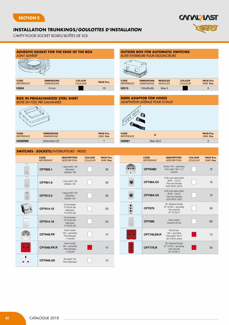
42
INSTALLATION TRUNKINGS/GOULOTTES D’INSTALLATION
CATALOGUE 2018
SecTION 2
CAvITY fLOOR SOCKET bOxES/BOÎtES DE SOL
CODERÉFÉRENCE
DimEnSiOnSdiMENsioNs
mODUlESModuLEs
COlOURCouLEuR
PACK Pcs.EMB. Pcs.
HG13 150x85x60 Max 3 6
CODERÉFÉRENCE
DimEnSiOnSdiMENsioNs
PACK Pcs.EMB. Pcs.
HG99Sm 343x343x122 1
CODERÉFÉRENCE
DimEnSiOnSdiMENsioNs
COlOURCouLEuR
PACK Pcs.
HG04 9 mm 10
adHeSive GaSKet for tHe edGe of tHe BoXJOINT ADHésIF
oUtSide BoX for aUtoMatic SWitcHeSBOITE EXTERIEURE POUR DIsJONCTEURs
BoX in PreGaLvaniZed SteeL SHeetBOITE EN TÔLE PRé-GALVANIséE
SideS adaPtor for HoSeSADAPTATEUR LATéRALE POUR TUyAUX
SWitcHeS - SocKetS/INTERRUPTEURs - PRIsEs
CODERÉFÉRENCE
DESCRiPtiOndEsCRiPtioN
COlOURCouLEuR
PACK Pcs.EMB. Pcs.
CP7600.11 gang switch 16A
Disjoncteur unipolaire 16A
30
CP7601.6 2 way switch 16Adéviateur 16A 30
CP7613.22 gang switch 16A
Disjoncteur bipolaire 16A
30
CP7614.10
Circuit breaker 1P+N10A 3kA
Disjoncteur1P+N10A 3kA
20
CP7614.16
Circuit breaker 1P+N16A 3kA
Disjoncteur1P+N16A 3kA
20
CP7648.FR
French socket 16A + groundingPrise française
+T sécurité
15
CP7648.FR.R
French socket 16A + groundingPrise française
+T sécurité
15
CP7648.UK UK socket 13APrise britannique 15
CODERÉFÉRENCE
DESCRiPtiOndEsCRiPtioN
COlOURCouLEuR
PACK Pcs.EMB. Pcs.
CP7648DSchuko 16A + groundingPrise shuko 16A +T C/
sécurité15
CP7664.C5
RJ45 voice-data socket 8P/8C - Cat.5 E
Prise voix-donnéesRJ45 8P/8C-CAT.5e
10
CP7664.C6
RJ45 voice-data socket 8P/8C - Cat.6 E
Prise voix-données RJ45 8P/8C-CAT.6
10
CP7679
ITA. Shuttered Socket 2P-10/16A + grounding
Prise sécurité2P-10/16A+T
30
CP7688 False moduleCouvercle du trou 80
CP7748.DS.R
Red Schuko 16A + grounding
Prise shuko 16A+T SIC-S/Terre central
15
CP7779.R
ITA. Shuttered Socket 2P-10/16A + grounding
Prise sécurité 2P-10/16A+T
30
CODERÉFÉRENCE
ØPACK Pcs.EMB. Pcs.
HG991 Max 28,5 2
®
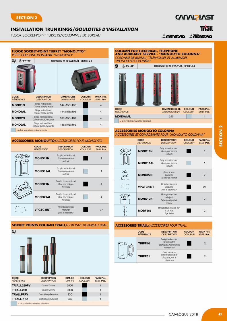
43CATALOGUE 2018
INSTALLATION TRUNKINGS/GOULOTTES D’INSTALLATION
SecT
ION
2
SecTION 2
SocKet PointS coLUMn triaLL/COLONNE DE BUREAU TRIALL
fLOOR SOCKET-pOINT TURRETS/cOLONNES DE BUREaU
CODERÉFÉRENCE
DESCRiPtiOndEsCRiPtioN
Dim. (H)diM. (h)
COlOURCouLEuR
PACK Pcs.EMB. Pcs.
tRiAll280PV Column/Colonne 3000 1
tRiAll280 Column/Colonne 3000 1
tRiAllPRPV Central body/Extension 930 1
tRiAllPRO Central body/Extension 930 1
= colour aluminium/couleur aluminium
CODERÉFÉRENCE
DimEnSiOnS (H)diMENsioNs (h)
COlOURCouLEuR
PACK Pcs.EMB. Pcs.
mOnOA1Al 295 1
= colour aluminium/couleur aluminium
acceSSorieS MonoLyto/ACCEssOIREs POUR MONOLyTO
CODERÉFÉRENCE
DESCRiPtiOndEsCRiPtioN
COlOURCouLEuR
PACK Pcs.EMB. Pcs.
mOnO11nBody for vertical turretCorps pour colonne
verticale1
mOnO11AlBody for vertical turretCorps pour colonne
verticale1
mOnO21nBase for horizontal turret
Base pour colonne horizontal
4
mOnO21AlBase for horizontal turret
Base pour colonne horizontal
4
VPGtC4intKit for bipolar mcbs
Plaquette pour le disjoncteur
27
acceSSorieS triaLL/ACCEssOIREs POUR TRIALL
CODERÉFÉRENCE
DESCRiPtiOndEsCRiPtioN
COlOURCouLEuR
PACK Pcs.EMB. Pcs.
tRiPP10
Front plates for socket. Wheelbase 108
Cadre pour mechanismes interaxe 108
2
tRiPP31Cover for autom.
differential switchesPlaquette pour le
disjoncteur
2
acceSSorieS MonoLyto coLonnaACCEssOIREs ET COMPOsANTs POUR “MONOLyTO COLONNA”
CODERÉFÉRENCE
DESCRiPtiOndEsCRiPtioN
COlOURCouLEuR
PACK Pcs.EMB. Pcs.
mOnO11nBody for vertical turretCorps pour colonne
verticale1
mOnO11AlBody for vertical turretCorps pour colonne
verticale1
mOnO22nCover + base
Couvercle et base de colonne
2
VPGtC4intKit for bipolar mcbs
Plaquette pour le disjoncteur
27
mOnO10n
Monolyto main part with joint
Extension et joint de colonne
2
mObF665Threaded bar M8x665 mm
+ M8 nutsTige filetee
2
coLonna
coLUMn for eLectricaL, teLePHone and aUXiLiary Service - “MonoLyto coLonna”COLONNE DE BUREAU, TéLéPHONIEs ET AUXILIAIREs“MONOLyTO COLONNA”
-5°/ +60° CONFORMING TO: lVD 2006/95/CE - EN 50085-2-4
fLoor SocKet-Point tUrret “MonoLyto”PETITE COLONNE MONTANTE “MONOLyTO”
-5°/ +60° CONFORMING TO: lVD 2006/95/CE - EN 50085-2-4
CODERÉFÉRENCE
DESCRiPtiOndEsCRiPtioN
DimEnSiOnSdiMENsioNs
COlOURCouLEuR
PACK Pcs.EMB. Pcs.
mOnO1n Single vertical turretColonne simple, vertical 144x156x196 4
mOnO1Al Single vertical turretColonne simple, vertical 144x156x196 4
mOnO2n Single horizontal turretColonne simple, horizontal 188x156x169 4
mOnO2Al Single horizontal turretColonne simple, horizontal 188x156x169 4
= colour aluminium/couleur aluminium

AIR CONDITIONING INSTALLATION➤ AIR CONDITIONING DUCTS➤ CONDENSATION DRAIN ACCESSORIES➤ bASES AND bRACKETS
Section 3
GOULOTTESDE CLIMATISATION➤ SYStèME DE GOULOttES pOUR L’aiR cONDitiONNé➤ accESSOiRES DE viDaNGE cONDENSatiON➤ BaSES Et SUppORtS

45CATALOGUE 2018
AIR CONDITIONING INSTALLATION/GOULOTTEs DE CLIMATIsATION
SeCT
ION
3
SeCTION 3
AIR CONDITIONING DUCTS/SYStèME DE GOULOttES pOUR L’aiR cONDitiONNé
cover jointJOINT DE COUVERCLE
CODERÉFÉRENCE
DimEnSiOnS (b x h)diMENsioNs (b x h)
PACK mEMB. m
COn65A 65x50 24
COn70A 70x55 20
COn80A 80x60 16
COn90A 90x65 16
COn125A 125x75 8
CODERÉFÉRENCE
FOR tRUnKinGPouR GouLottE
PACK Pcs.EMB. Pcs.
COnG30 35x30 25
COnG65 65x50 25
COnG70 70x55 25
COnG80 80x60 25
COnG90 90x65 25
COnG125 125x75 25
inner Bend ANGLE INTERNE
oUter BendANGLE EXTéRIEUR
90° fLat BendCOURBE PLANE
trUnKinGS WitH WraP-aroUnd cover WitHProtective fiLM - coLoUr WHite - LenGtH 2 mGOULOTTEs ENVELOPPANTE AVEC FILM DE PROTECTION - COULEUR BLANC - LONGUEUR 2 m
SElF-EXTINGuISHING ul94-V0
trUnKinG WitH SnaP-on cover WitH Protective fiLM coLoUr WHite - LenGtH 2 mGOULOTTE Á DéCLIC MUNIs DE FILM DE PROTECTION COULEUR BLANC - LONGUEUR 2 m
CODERÉFÉRENCE
DimEnSiOnS (b x h)diMENsioNs (b x h)
PACK mEMB. m
COn30* 35x30 64
COn65 (NEW) 65x50 28
COn70 70x55 24
COn80 (NEW) 80x60 20
COn90 90x65 16
COn125 125x75 8
* Without protective film/sans film de protection
CODERÉFÉRENCE
FOR tRUnKinGPouR GouLottE
PACK Pcs.EMB. Pcs.
COnCP30 35x30 20
COnCP65 65x50 10
COnCP70 70x55 10
COnCP80 80x60 10
COnCP90 90x65 10
COnCP125 125x75 10
CODERÉFÉRENCE
FOR tRUnKEnGPouR GouLottE
PACK Pcs.EMB. Pcs.
COnAE30 35x30 20
COnAE65 65x50 10
COnAE70 70x55 10
COnAE80 80x60 10
COnAE90 90x65 10
COnAE125 125x75 10
CODERÉFÉRENCE
FOR tRUnKinGPouR GouLottE
PACK Pcs.EMB. Pcs.
COnAi30 35x30 20
COnAi65 65x50 10
COnAi70 70x55 10
COnAi80 80x60 10
COnAi90 90x65 10
COnAi125 125x75 10
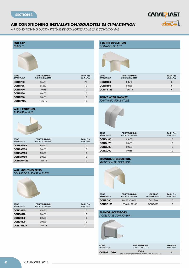
46
AIR CONDITIONING INSTALLATION/GOULOTTES DE CLIMATISATION
CATALOGUE 2018
SeCTION 3
AIR CONDITIONING DUCTS/SYStèME DE GOULOttES pOUR L’aiR cONDitiONNé
trUnKinG redUctionRéDUCTION DE GOULOTTE
t-joint deviationDéRIVATION EN “T”
joint WitH GaSKetJOINT AVEC GUARNITURE
fLanGe acceSSoryACCEssOIRE CONVOyEUR
CODERÉFÉRENCE
FOR tRUnKinGPouR GouLottE
USE FEAtutiLiZER AVEC
PACK Pcs.EMB. Pcs.
COnRD90 90x65 - 70x55 CONG90 10
COnRD125 125x65 - 90x65 CONG125 10
CODERÉFÉRENCE
FOR tRUnKinGPouR GouLottE
PACK Pcs.EMB. Pcs.
COnVG110-90 90x65 (and 70x55 using CONRD90/et 70X55 à l’aide de CONRD90)
8
CODERÉFÉRENCE
FOR tRUnKinGPouR GouLottE
PACK Pcs.EMB. Pcs.
COntP30 35x30 20
COntP65 65x50 10
COntP70 70x55 10
COntP80 80x60 10
COntP90 90x65 10
COntP125 125x75 10
CODERÉFÉRENCE
FOR tRUnKinGPouR GouLottE
PACK Pcs.EMB. Pcs.
COnPAm65 65x50 10
COnPAm70 70x55 10
COnPAm80 80x60 10
COnPAm90 90x65 10
COnPAm125 125x75 10
CODERÉFÉRENCE
FOR tRUnKinGPouR GouLottE
PACK Pcs.EMB. Pcs.
COnCm65 65x50 10
COnCm70 70x55 10
COnCm80 80x60 10
COnCm90 90x65 10
COnCm125 125x75 10
CODERÉFÉRENCE
FOR tRUnKinGPouR GouLottE
PACK Pcs.EMB. Pcs.
COnGU65 65x50 10
COnGU70 70x55 10
COnGU80 80x60 10
COnGU90 90x65 10
CODERÉFÉRENCE
FOR tRUnKinGPouR GouLottE
PACK Pcs.EMB. Pcs.
COnCt80 80x60 6
COnCt90 90x65 6
COnCt125 125x75 6
end caPEMBOUT
WaLL roUtinGPAssAGE à MUR
WaLL-roUtinG BendCOURBE DE PAssAGE à PAROI
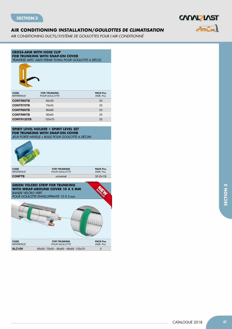
47CATALOGUE 2018
AIR CONDITIONING INSTALLATION/GOULOTTEs DE CLIMATIsATION
SeCT
ION
3
SeCTION 3
AIR CONDITIONING DUCTS/SYStèME DE GOULOttES pOUR L’aiR cONDitiONNé
SPirit LeveL HoLder + SPirit LeveL Set for trUnKinG WitH SnaP-on coverJEUX PORTE-NIVELLE + BULLE POUR GOULOTTE A DéCLIN
CODERÉFÉRENCE
FOR tRUnKinGPouR GouLottE
PACK Pcs.EMB. Pcs.
COnPtb universal 50 (5x10)
croSS-arM WitH HoSe cLiP for trUnKinG WitH SnaP-on coverTRAVERsE AVEC AILEs FERME-TUyAU POUR GOULOTTE A DéCLIC
CODERÉFÉRENCE
FOR tRUnKinGPouR GouLottE
PACK Pcs.EMB. Pcs.
COntR65tb 65x50 25
COntR70tb 70x55 25
COntR80tb 80x60 25
COntR90tb 90x65 25
COntR125tb 125x75 25
Green veLcro StriP for trUnKinG WitH WraP-aroUnd cover 10 X 5 MMBANDE VELCRO VERT POUR GOULOTTE ENVELOPPANTE 10 X 5 mm
CODERÉFÉRENCE
FOR tRUnKinGPouR GouLottE
PACK Pcs.EMB. Pcs.
VlC10V 65x50 -70x55 - 80x60 - 90x65 -125x75 5
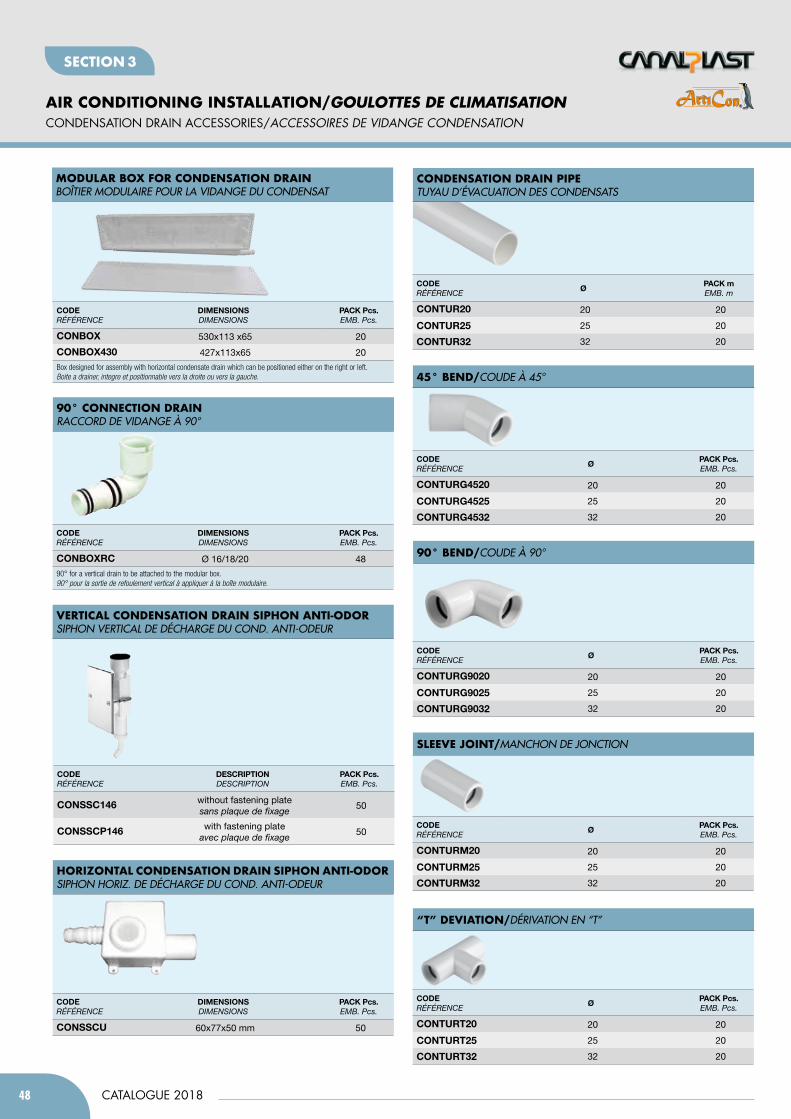
48
AIR CONDITIONING INSTALLATION/GOULOTTES DE CLIMATISATION
CATALOGUE 2018
SeCTION 3
CONDENSATION DRAIN ACCESSORIES/accESSOiRES DE viDaNGE cONDENSatiON
CODERÉFÉRENCE
DimEnSiOnSdiMENsioNs
PACK Pcs.EMB. Pcs.
COnSSCU 60x77x50 mm 50
CODERÉFÉRENCE
ØPACK mEMB. m
COntUR20 20 20
COntUR25 25 20
COntUR32 32 20
CODERÉFÉRENCE
ØPACK Pcs.EMB. Pcs.
COntURG4520 20 20
COntURG4525 25 20
COntURG4532 32 20
CODERÉFÉRENCE
ØPACK Pcs.EMB. Pcs.
COntURm20 20 20
COntURm25 25 20
COntURm32 32 20
CODERÉFÉRENCE
ØPACK Pcs.EMB. Pcs.
COntURG9020 20 20
COntURG9025 25 20
COntURG9032 32 20
CODERÉFÉRENCE
ØPACK Pcs.EMB. Pcs.
COntURt20 20 20
COntURt25 25 20
COntURt32 32 20
HoriZontaL condenSation drain SiPHon anti-odorsIPHON HORIZ. DE DéCHARGE DU COND. ANTI-ODEUR
condenSation drain PiPeTUyAU D’éVACUATION DEs CONDENsATs
45° Bend/COUDE à 45°
SLeeve joint/MANCHON DE JONCTION
90° Bend/COUDE à 90°
“t” deviation/DéRIVATION EN “T”
CODERÉFÉRENCE
DESCRiPtiOndEsCRiPtioN
PACK Pcs.EMB. Pcs.
COnSSC146 without fastening platesans plaque de fixage
50
COnSSCP146 with fastening plateavec plaque de fixage
50
verticaL condenSation drain SiPHon anti-odorsIPHON VERTICAL DE DéCHARGE DU COND. ANTI-ODEUR
CODERÉFÉRENCE
DimEnSiOnSdiMENsioNs
PACK Pcs.EMB. Pcs.
COnbOxRC Ø 16/18/20 48
90° for a vertical drain to be attached to the modular box. 90° pour la sortie de refoulement vertical à appliquer à la boîte modulaire.
90° connection drainRACCORD DE VIDANGE à 90°
CODERÉFÉRENCE
DimEnSiOnSdiMENsioNs
PACK Pcs.EMB. Pcs.
COnbOx 530x113 x65 20
COnbOx430 427x113x65 20
Box designed for assembly with horizontal condensate drain which can be positioned either on the right or left.Boite a drainer, integre et positionnable vers la droite ou vers la gauche.
ModULar BoX for condenSation drainBOîTIER MODULAIRE POUR LA VIDANGE DU CONDENsAT
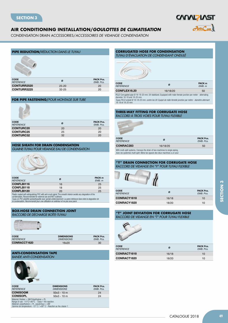
49CATALOGUE 2018
AIR CONDITIONING INSTALLATION/GOULOTTEs DE CLIMATIsATION
SeCT
ION
3
SeCTION 3
CONDENSATION DRAIN ACCESSORIES/accESSOiRES DE viDaNGE cONDENSatiON
CODERÉFÉRENCE
ØPACK Pcs.EMB. Pcs.
COntURC20 20 20COntURC25 25 20COntURC32 32 20
CODERÉFÉRENCE
ØPACK Pcs.EMB. Pcs.
COntURR2520 25-20 20COntURR3225 32-25 20
for PiPe faSteninG/POUR MONTAGE sUR TUBE
PiPe redUction/RéDUCTION DANs LE TUyAU
CODERÉFÉRENCE
ØPACK Pcs.EMB. Pcs.
COnRACt1618 16/18 10
COnRACt1820 18/20 10
CODERÉFÉRENCE
DimEnSiOnSdiMENsioNs
PACK Pcs.EMB. Pcs.
COniSOGm 50x3 - 10 m 24COniSOPl 50x3 - 10 m 24Material: Rubber = GM Polyethylene = PLRange of use: -15°C/+80°C. - Class 1 fire reaction.Material: polyethylene = PL, caoutchouc = GM Gamme de temperature: -15° C / +80° C - Reaction au feu classe 1.
anti-condenSation taPeBANDE ANTI-CONDENsATION
CODERÉFÉRENCE
ØPACK Pcs.EMB. Pcs.
COnRAC283 16/18/20 50
With multi-split systems. Conveys the drain of two machines to single piping.Avec les systemes multi-split. Mene les egouts des deux machines a un seul.
CODERÉFÉRENCE
ØPACK mEMB. m
COnFlbi116 16 25COnFlbi118 18 25COnFlbi120 20 25Plastic coated self-extinguishing PVC with anti-crush spiral. The smooth interior avoids any stagnation of thecondensation. Recommended for external use and NOT subtrack.Tuyau en PVC plastifié autoextinguible avec spirale antiécrasement. La paroi intérieure lisse évite la stagnation dela condensation. Recommandé pour une utilisation en extérieur et ne pas sous paroi.
tHree-Way fittinG for corrUGate HoSeRACCORD à TROIs VOIEs POUR TUyAU FLEXIBLE
HoSe SHeatH for drain condenSationGUAINE-TUyAU POUR VIDANGE EAU DE CONDENsATION
CODERÉFÉRENCE
ØPACK mEMB. m
COnFlEx18.20 16/18/20 50PELD Corrugated pipe Ø 16-18-20 mm. UV stabilized. Equipped with male-female junction per meter - alternating diameter 16-18 and 18-20 mm.Tuyau PELD ondulé Ø 16-18-20 mm. contre les UV. Equipé de mâle-femelle jonction par mètre - diamètre alternant 16-18 et 18-20 mm.
corrUGated HoSe for condenSationTUyAU D’éVACUATION DE CONDENsANT ONDULé
CODERÉFÉRENCE
ØPACK Pcs.EMB. Pcs.
COnRACy1618 16/18 10
COnRACy1820 18/20 10
“y” drain connection for corrUGate HoSeRACCORD DE VIDANGE EN “y” POUR TUyAU FLEXIBLE
“t” joint deviation for corrUGate HoSeRACCORD DE VIDANGE EN “T” POUR TUyAU FLEXIBLE
CODERÉFÉRENCE
DimEnSiOnSdiMENsioNs
PACK Pcs.EMB. Pcs.
COnRACCt1620 16x20 30
BoX-HoSe drain connection jointRACCORD DE DéCHARGE BOîTE-TUyAU
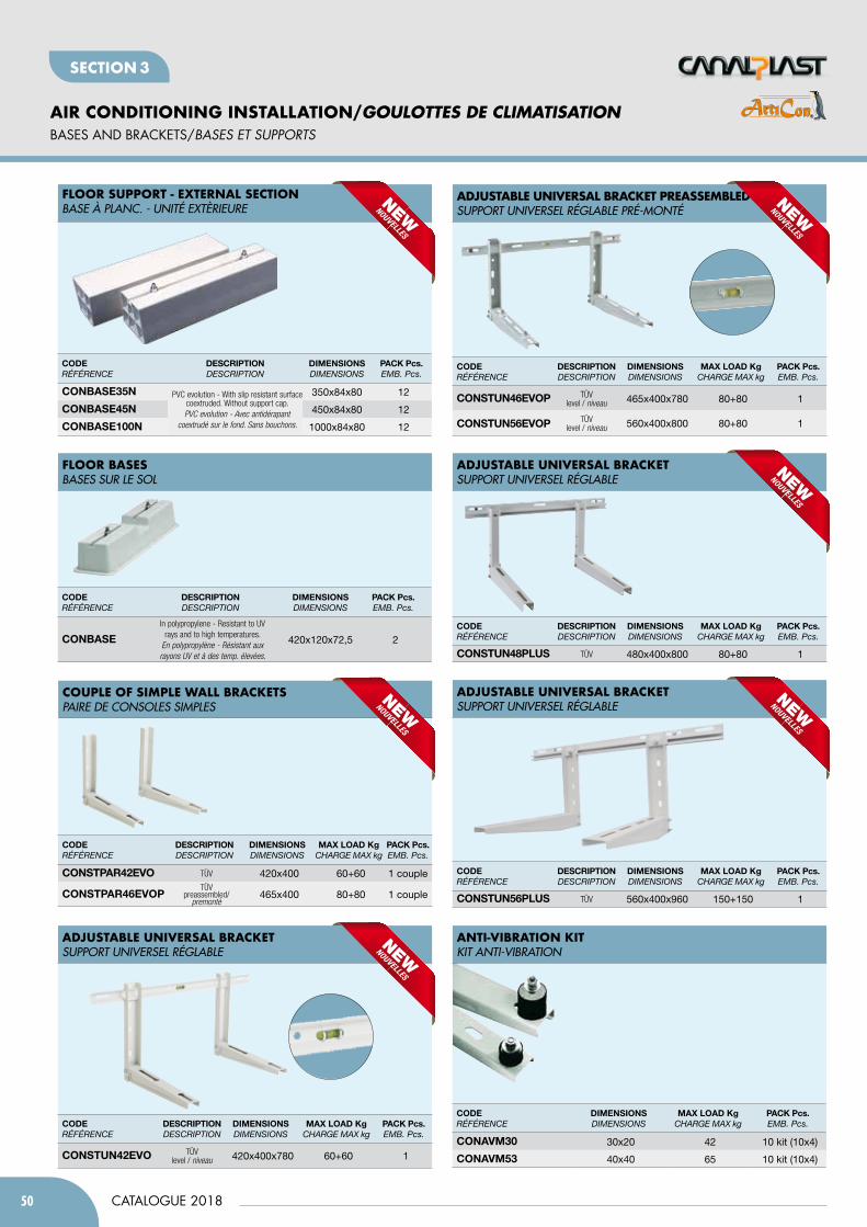
50
AIR CONDITIONING INSTALLATION/GOULOTTES DE CLIMATISATION
CATALOGUE 2018
SeCTION 3
bASES AND bRACKETS/BaSES Et SUppORtS
CODERÉFÉRENCE
DimEnSiOnSdiMENsioNs
mAx lOAD KgChARGE MAx kg
PACK Pcs.EMB. Pcs.
COnAVm30 30x20 42 10 kit (10x4)
COnAVm53 40x40 65 10 kit (10x4)
anti-viBration KitKIT ANTI-VIBRATION
CODERÉFÉRENCE
DESCRiPtiOndEsCRiPtioN
DimEnSiOnSdiMENsioNs
mAx lOAD KgChARGE MAx kg
PACK Pcs.EMB. Pcs.
COnStUn42EVO TÜVlevel / niveau 420x400x780 60+60 1
CODERÉFÉRENCE
DESCRiPtiOndEsCRiPtioN
DimEnSiOnSdiMENsioNs
mAx lOAD KgChARGE MAx kg
PACK Pcs.EMB. Pcs.
COnStUn46EVOP TÜVlevel / niveau 465x400x780 80+80 1
COnStUn56EVOP TÜVlevel / niveau 560x400x800 80+80 1
CODERÉFÉRENCE
DESCRiPtiOndEsCRiPtioN
DimEnSiOnSdiMENsioNs
mAx lOAD KgChARGE MAx kg
PACK Pcs.EMB. Pcs.
COnStUn48PlUS TÜV 480x400x800 80+80 1
CODERÉFÉRENCE
DESCRiPtiOndEsCRiPtioN
DimEnSiOnSdiMENsioNs
mAx lOAD KgChARGE MAx kg
PACK Pcs.EMB. Pcs.
COnStUn56PlUS TÜV 560x400x960 150+150 1
adjUStaBLe UniverSaL BracKetsUPPORT UNIVERsEL RéGLABLE
adjUStaBLe UniverSaL BracKet PreaSSeMBLed sUPPORT UNIVERsEL RéGLABLE PRé-MONTé
adjUStaBLe UniverSaL BracKetsUPPORT UNIVERsEL RéGLABLE
adjUStaBLe UniverSaL BracKetsUPPORT UNIVERsEL RéGLABLE
fLoor BaSeSBAsEs sUR LE sOL
fLoor SUPPort - eXternaL SectionBAsE à PLANC. - UNITé EXTèRIEURE
CODERÉFÉRENCE
DESCRiPtiOndEsCRiPtioN
DimEnSiOnSdiMENsioNs
PACK Pcs.EMB. Pcs.
COnbASEIn polypropylene - Resistant to UV
rays and to high temperatures.En polypropylène - Résistant auxrayons UV et à des temp. élevées.
420x120x72,5 2
CODERÉFÉRENCE
DESCRiPtiOndEsCRiPtioN
DimEnSiOnSdiMENsioNs
PACK Pcs.EMB. Pcs.
COnbASE35n PVC evolution - With slip resistant surface coextruded. Without support cap.PVC evolution - Avec antidérapant
coextrudé sur le fond. Sans bouchons.
350x84x80 12
COnbASE45n 450x84x80 12
COnbASE100n 1000x84x80 12
CODERÉFÉRENCE
DESCRiPtiOndEsCRiPtioN
DimEnSiOnSdiMENsioNs
mAx lOAD KgChARGE MAx kg
PACK Pcs.EMB. Pcs.
COnStPAR42EVO TÜV 420x400 60+60 1 couple
COnStPAR46EVOPTÜV
preassembled/premontè
465x400 80+80 1 couple
coUPLe of SiMPLe WaLL BracKetSPAIRE DE CONsOLEs sIMPLEs
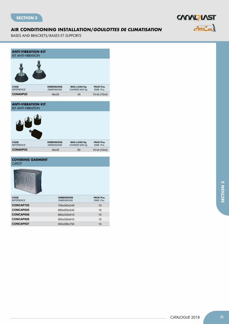
51CATALOGUE 2018
AIR CONDITIONING INSTALLATION/GOULOTTEs DE CLIMATIsATION
SeCT
ION
3
SeCTION 3
bASES AND bRACKETS/BaSES Et SUppORtS
CODERÉFÉRENCE
DimEnSiOnSdiMENsioNs
mAx lOAD KgChARGE MAx kg
PACK Pcs.EMB. Pcs.
COnAVP20 48x20 45 10 kit (10x4)
CODERÉFÉRENCE
DimEnSiOnSdiMENsioNs
mAx lOAD KgChARGE MAx kg
PACK Pcs.EMB. Pcs.
COnAVP53 40x40 65 10 kit (10x4)
anti-viBration KitKIT ANTI-VIBRATION
anti-viBration KitKIT ANTI-VIBRATION
CODERÉFÉRENCE
DimEnSiOnSdiMENsioNs
PACK Pcs.EMB. Pcs.
COnCAP725 700x265x540 10
COnCAP825 800x265x540 10
COnCAP836 860x330x610 10
COnCAP936 950x330x610 10
COnCAP937 950x380x750 10
coverinG GarMentCAPOT

ELECTRICAL EqUIpmENT INSTALLATION
MATÉRIEL ÉLECTRIQUE D’INSTALLATION
Section 4
➤ fLUSH JUNCTION bOxES➤ JUNCTION bOxES fOR WALL MOUNTING➤ fLUSH AND WALL DISTRIbUTION bOARDS➤ CIRCUIT bREAKERS AND fUSE HOLDERS➤ fITTINGS, fASTENINGS, CONNECTORS AND ACCESSORIES➤ fISHTApES AND HOSES
➤ BOÎtES D’ENcaStREMENt➤ BOÎtES DE DéRivatiON a ENcaStRER➤ cOffREtS DE DiStRiBUtiON➤ DiSjONctEURS, BLOcS DifféRENtiELS Et cOUpE ciRcUit➤ MaNcHONS, B. DE cONNExiONS Et accESS. DE fixatiON➤ tiRE fiLS Et GaiNES
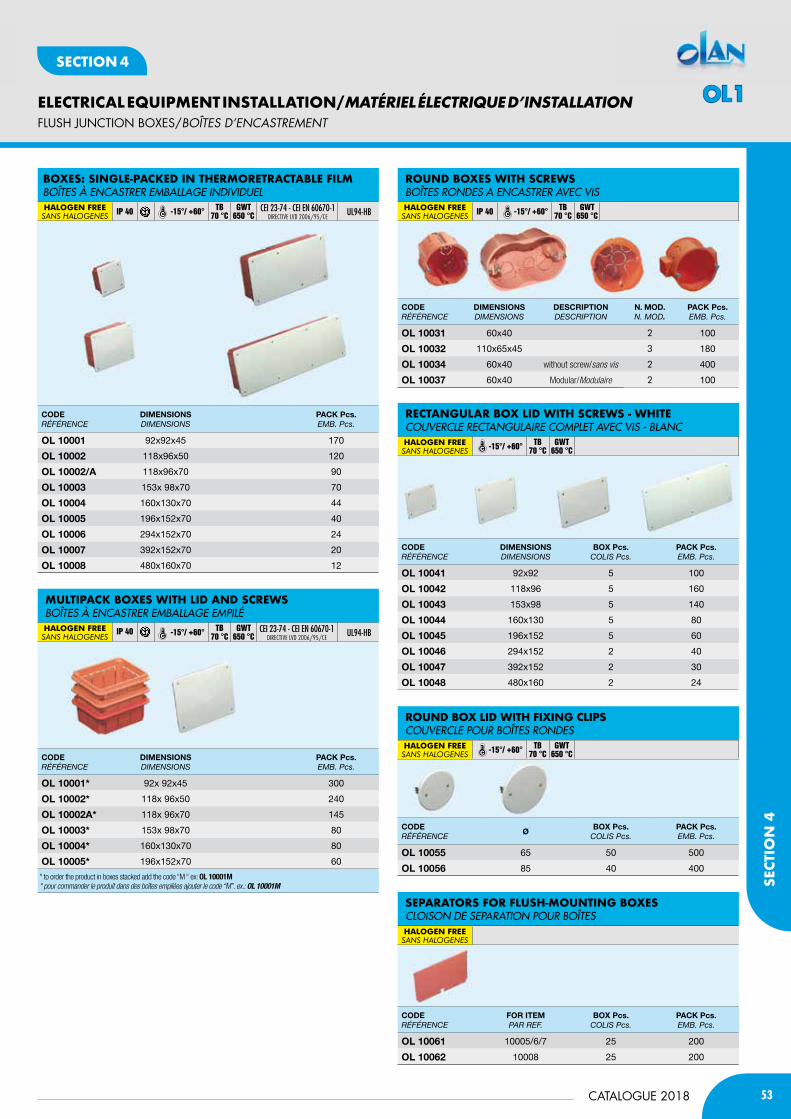
53CATALOGUE 2018
ELECTRICAL EQUIPMENT INSTALLATION/MATÉRIEL ÉLECTRIQUE D’INSTALLATION
SECT
ION
4
SECTION 4
CODERÉFÉRENCE
DimEnSiOnSdiMENsioNs
PACK Pcs.EMB. Pcs.
Ol 10001 92x92x45 170
Ol 10002 118x96x50 120
Ol 10002/A 118x96x70 90
Ol 10003 153x 98x70 70
Ol 10004 160x130x70 44
Ol 10005 196x152x70 40
Ol 10006 294x152x70 24
Ol 10007 392x152x70 20
Ol 10008 480x160x70 12
CODERÉFÉRENCE
ØbOx Pcs.
CoLis Pcs.PACK Pcs.EMB. Pcs.
Ol 10055 65 50 500
Ol 10056 85 40 400
CODERÉFÉRENCE
FOR itEm PAR REF.
bOx Pcs.CoLis Pcs.
PACK Pcs.EMB. Pcs.
Ol 10061 10005/6/7 25 200
Ol 10062 10008 25 200
CODERÉFÉRENCE
DimEnSiOnSdiMENsioNs
bOx Pcs.CoLis Pcs.
PACK Pcs.EMB. Pcs.
Ol 10041 92x92 5 100
Ol 10042 118x96 5 160
Ol 10043 153x98 5 140
Ol 10044 160x130 5 80
Ol 10045 196x152 5 60
Ol 10046 294x152 2 40
Ol 10047 392x152 2 30
Ol 10048 480x160 2 24
CODERÉFÉRENCE
DimEnSiOnSdiMENsioNs
DESCRiPtiOndEsCRiPtioN
n. mOD.N. Mod.
PACK Pcs.EMB. Pcs.
Ol 10031 60x40 2 100
Ol 10032 110x65x45 3 180
Ol 10034 60x40 without screw/sans vis 2 400
Ol 10037 60x40 Modular/Modulaire 2 100
rectanGULar BoX Lid WitH ScreWS - WHiteCOUVERCLE RECTANGULAIRE COMPLET AVEC VIs - BLANCHALOGEN FREEsAns HALogenes -15°/ +60° TB
70 °CGWT
650 °C
roUnd BoX Lid WitH fiXinG cLiPSCOUVERCLE POUR BOîTEs RONDEsHALOGEN FREEsAns HALogenes -15°/ +60° TB
70 °CGWT
650 °C
SeParatorS for fLUSH-MoUntinG BoXeSCLOIsON DE sEPARATION POUR BOîTEsHALOGEN FREEsAns HALogenes
roUnd BoXeS WitH ScreWSBOîTEs RONDEs A ENCAsTRER AVEC VIsHALOGEN FREEsAns HALogenes IP 40 -15°/ +60° TB
70 °CGWT
650 °C
CODERÉFÉRENCE
DimEnSiOnSdiMENsioNs
PACK Pcs.EMB. Pcs.
Ol 10001* 92x 92x45 300
Ol 10002* 118x 96x50 240
Ol 10002A* 118x 96x70 145
Ol 10003* 153x 98x70 80
Ol 10004* 160x130x70 80
Ol 10005* 196x152x70 60
* to order the product in boxes stacked add the code “M “ ex: OL 10001M* pour commander le produit dans des boîtes empilées ajouter le code “M”. ex.: OL 10001M
MULtiPacK BoXeS WitH Lid and ScreWSBOîTEs à ENCAsTRER EMBALLAGE EMPILéHALOGEN FREEsAns HALogenes
IP 40 -15°/ +60° TB 70 °C
GWT 650 °C
CEI 23-74 - CEI EN 60670-1DIRECTIVE LVD 2006/95/CE
ul94-HB
fLUSH JUNCTION bOxES/BOÎtES D’ENcaStREMENt
BoXeS: SinGLe-PacKed in tHerMoretractaBLe fiLMBOîTEs à ENCAsTRER EMBALLAGE INDIVIDUELHALOGEN FREEsAns HALogenes IP 40 -15°/ +60° TB
70 °CGWT
650 °CCEI 23-74 - CEI EN 60670-1
DIRECTIVE LVD 2006/95/CEul94-HB
OL1
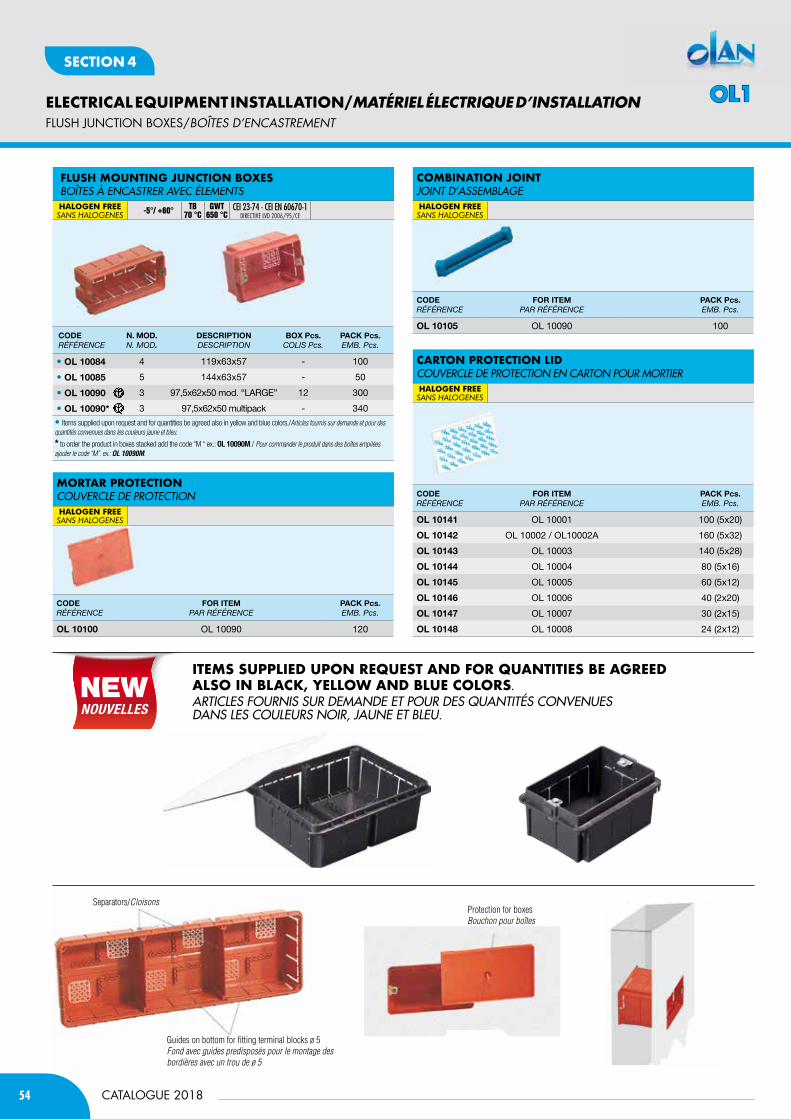
54
ELECTRICAL EQUIPMENT INSTALLATION/MATÉRIEL ÉLECTRIQUE D’INSTALLATION
CATALOGUE 2018
SECTION 4
CODERÉFÉRENCE
n. mOD.N. Mod.
DESCRiPtiOndEsCRiPtioN
bOx Pcs.CoLis Pcs.
PACK Pcs.EMB. Pcs.
• Ol 10084 4 119x63x57 - 100
• Ol 10085 5 144x63x57 - 50
• Ol 10090 3 97,5x62x50 mod. “LARGE” 12 300
• Ol 10090* 3 97,5x62x50 multipack - 340
• Items supplied upon request and for quantities be agreed also in yellow and blue colors./Articles fournis sur demande et pour des quantités convenues dans les couleurs jaune et bleu.
* to order the product in boxes stacked add the code “M “ ex.: OL 10090M./ Pour commander le produit dans des boîtes empilées ajouter le code “M”. ex.: OL 10090M.
CODERÉFÉRENCE
FOR itEmPAR RÉFÉRENCE
PACK Pcs.EMB. Pcs.
Ol 10100 OL 10090 120
CODERÉFÉRENCE
FOR itEmPAR RÉFÉRENCE
PACK Pcs.EMB. Pcs.
Ol 10105 OL 10090 100
CODERÉFÉRENCE
FOR itEmPAR RÉFÉRENCE
PACK Pcs.EMB. Pcs.
Ol 10141 OL 10001 100 (5x20)
Ol 10142 OL 10002 / OL10002A 160 (5x32)
Ol 10143 OL 10003 140 (5x28)
Ol 10144 OL 10004 80 (5x16)
Ol 10145 OL 10005 60 (5x12)
Ol 10146 OL 10006 40 (2x20)
Ol 10147 OL 10007 30 (2x15)
Ol 10148 OL 10008 24 (2x12)
carton Protection Lid COUVERCLE DE PROTECTION EN CARTON POUR MORTIERHALOGEN FREEsAns HALogenes
Mortar ProtectionCOUVERCLE DE PROTECTIONHALOGEN FREEsAns HALogenes
coMBination jointJOINT D’AssEMBLAGEHALOGEN FREEsAns HALogenes
fLUSH JUNCTION bOxES/BOÎtES D’ENcaStREMENt
Separators/Cloisons
Guides on bottom for fitting terminal blocks ø 5Fond avec guides predisposés pour le montage des bordières avec un trou de ø 5
Protection for boxesBouchon pour boîtes
iteMS SUPPLied UPon reQUeSt and for QUantitieS Be aGreed aLSo in BLacK, yeLLoW and BLUe coLorS.ARTICLEs FOURNIs sUR DEMANDE ET POUR DEs QUANTITés CONVENUEs DANs LEs COULEURs NOIR, JAUNE ET BLEU.
OL1
fLUSH MoUntinG jUnction BoXeSBOîTEs à ENCAsTRER AVEC éLEMENTsHALOGEN FREEsAns HALogenes -5°/ +60° TB
70 °CGWT
650 °CCEI 23-74 - CEI EN 60670-1
DIRECTIVE LVD 2006/95/CE
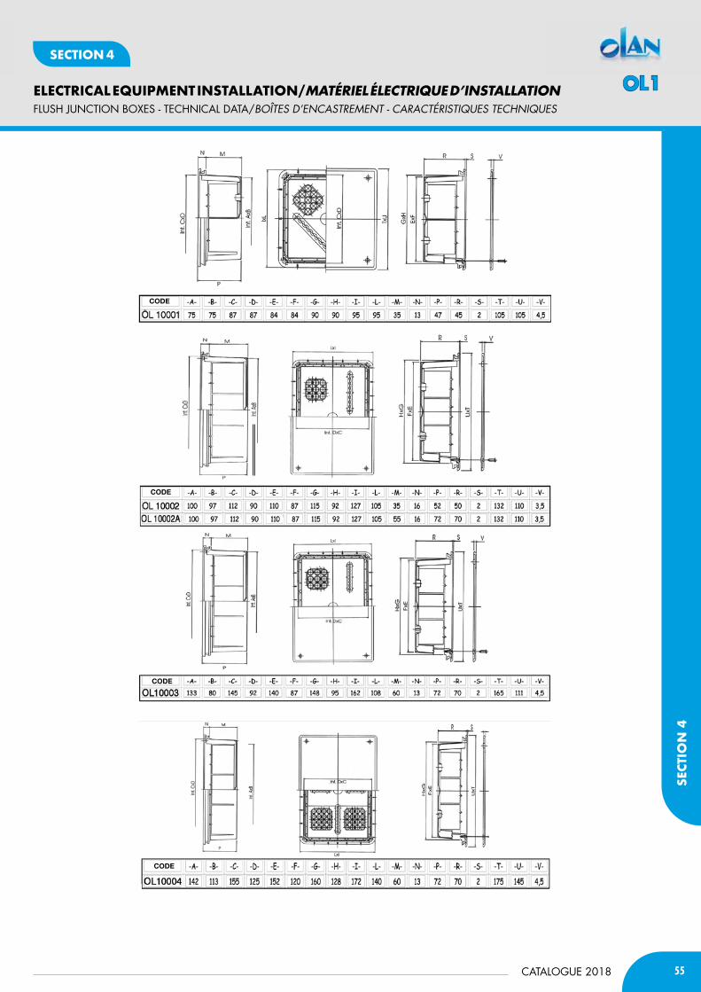
55CATALOGUE 2018
ELECTRICAL EQUIPMENT INSTALLATION/MATÉRIEL ÉLECTRIQUE D’INSTALLATION
SECT
ION
4
SECTION 4
fLUSH JUNCTION bOxES - TECHNICAL DATA/BOÎtES D’ENcaStREMENt - caRactéRiStiQUES tEcHNiQUES
CODE
CODE
CODE
CODE
OL1
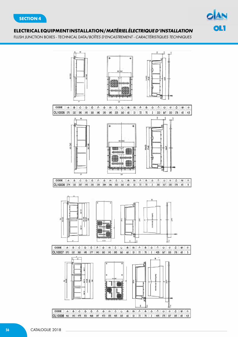
56
ELECTRICAL EQUIPMENT INSTALLATION/MATÉRIEL ÉLECTRIQUE D’INSTALLATION
CATALOGUE 2018
SECTION 4
fLUSH JUNCTION bOxES - TECHNICAL DATA/BOÎtES D’ENcaStREMENt - caRactéRiStiQUES tEcHNiQUES
CODE
CODE
CODE
CODE
OL1

57CATALOGUE 2018
ELECTRICAL EQUIPMENT INSTALLATION/MATÉRIEL ÉLECTRIQUE D’INSTALLATION
SECT
ION
4
SECTION 4
CODE n° liEUx
CODE
CODE
CODE
fLUSH JUNCTION bOxES - TECHNICAL DATA/BOÎtES D’ENcaStREMENt - caRactéRiStiQUES tEcHNiQUES
OL1

58
ELECTRICAL EQUIPMENT INSTALLATION/MATÉRIEL ÉLECTRIQUE D’INSTALLATION
CATALOGUE 2018
SECTION 4
JUNCTION bOxES fOR WALL MOUNTING/BOÎtES DE DéRivatiON
j. B. WitH MeMBrane GLand and QUicK fiXinG 1/4 tUrnBOîTEs AVEC PAssECABLEs COUVERCLE - VIs 1/4 DE TOURTECHNOPOLYMER
UL94-HB IP 55 -15°/ +60° TB75 °C
GWT650 °C IK 07
CEI EN 60 670-1CEI EN 60 670-22
Directive LVD 2006/95/CE
CODERÉFÉRENCE
DimEnSiOnSdiMENsioNs
n. EntRiESN. ENtRÉEs
SCREW COVERBouChoNs
PACK Pcs.EMB. Pcs.
Ol 20080 105x105x50 7 Ø 15 72
Ol 20112 150x110x70 10 Ø 16 45
* For a double and complete insulation use plastic screw cover (p. 61)/Double et complète isolation en utilisant les bouchons (p. 61)
jUnction BoXeS WitH roUnded PreSSUre LidBOîTEs COUVERCLE CONVEXE Á PREssION TECHNOPOLYMER
UL94-HB IP 44 -5°/ +60° TB75 °C
GWT650 °C IK 07
CEI EN 60 670-1CEI EN 60 670-22
Directive LVD 2006/95/CE
CODERÉFÉRENCE
DimEnSiOnSdiMENsioNs
n. EntRiESN. ENtRÉEs
SCREW COVERBouChoNs
PACK Pcs.EMB. Pcs.
• Ol 20001 ø 65x35 4 Ø 12 150 (30x5)
• Ol 20002 ø 80x40 4 Ø 12 160 (32x5)
• Ol 20003 80x80x40 6 Ø 14 160 (32x5)
Ol 20006 80x80x40 6 Ø 14 160 (32x5) • with membrane gland/avec passecables with knockouts/avec paroies pretrouée
* For a double and complete insulation use plastic screw cover (p. 61)/Double et complète isolation en utilisant les bouchons (p. 61)
*
SMootH-Sided j. BoXeS WitH QUicK fiXinG 1/4 tUrnBOÎTES cOuvErclE avEc viS 1/4 DE TOur - parOiES liSSES
HALOGEN FREEsAns HALogenes IP 56 -15°/ +60° TB
120 °CGWT
850 °C IK 08 ul94-HB
CODERÉFÉRENCE
DimEnSiOnSdiMENsioNs
SCREW COVERBouChoNs
PACK Pcs.EMB. Pcs.
Ol 20422 150x110x70 Ø 16 45
• Ol 20225 300x220x120 Ø 21 6
• Ol 20226 380x300x120 Ø 21 4
• hinged lid/couvercle avec charnière
* For a double and complete insulation use plastic screw cover (p. 61)/Double et complète isolation en utilisant les bouchons (p. 61)
*
CODERÉFÉRENCE
DimEnSiOnSdiMENsioNs
n. EntRiESN. ENtRÉEs
SCREW COVERBouChoNs
PACK Pcs.EMB. Pcs.
Ol 20009 80x80x40 6 Ø 16 160 (32x5)
* For a double and complete insulation use plastic screw cover (p. 61)/Double et complète isolation en utilisant les bouchons (p. 61)
j. BoXeS WitH MeMBrane GLand and fLat PreSSUre Lid BOîTEs COUVERCLE PLAT A PREssION - ET PAssECABLEsTECHNOPOLYMER
UL94-HB IP 55 -15°/ +60° TB75 °C
GWT650 °C IK 07*
SMootH-Sided jUnction BoXeS QUicK fiXinG 1/4 tUrnBOîTEs PAROIs LIssEs AVEC COUVERCLE ET VIs 1/4 DE TOURTECHNOPOLYMER
UL94-HB IP 56 -15°/ +60° TB75 °C
GWT650 °C IK 07
CEI EN 60 670-1CEI EN 60 670-22
Directive LVD 2006/95/CE
CODERÉFÉRENCE
DimEnSiOnSdiMENsioNs
SCREW COVERBouChoNs
PACK Pcs.EMB. Pcs.
Ol 20070 105x105x50 Ø 15 96
Ol 20122 150x110x70 Ø 16 45
* For a double and complete insulation use plastic screw cover (p. 61)/Double et complète isolation en utilisant les bouchons (p. 61)
*
SMootH-Sided j. B. HinGed oPeninG QUicK fiXinG 1/4 tUrnBOîTEs COUVERCLE Á CHARNIèRE PAROIEs LIssEs VIs 1/4 DE TOURTECHNOPOLYMER
UL94-HB IP 56 -15°/ +60° TB75 °C
GWT650 °C IK 07
CEI EN 60 670-1CEI EN 60 670-22
Directive LVD 2006/95/CE
CODERÉFÉRENCE
DimEnSiOnSdiMENsioNs
SCREW COVERBouChoNs
PACK Pcs.EMB. Pcs.
Ol 20025 300x220x120 Ø 21 6
Ol 20026 380x300x120 Ø 21 6
* For a double and complete insulation use plastic screw cover (p. 61)/Double et complète isolation en utilisant les bouchons (p. 61)
*
OL2
*
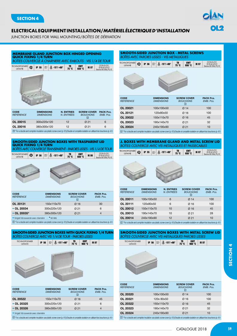
59CATALOGUE 2018
ELECTRICAL EQUIPMENT INSTALLATION/MATÉRIEL ÉLECTRIQUE D’INSTALLATION
SECT
ION
4
SECTION 4
JUNCTION bOxES fOR WALL MOUNTING/BOÎtES DE DéRivatiON
CODERÉFÉRENCE
DimEnSiOnSdiMENsioNs
SCREW COVERBouChoNs
PACK Pcs.EMB. Pcs.
Ol 20522 150x110x70 Ø 16 45
• Ol 20325 300x220x120 Ø 21 6
• Ol 20326 380x300x120 Ø 21 4
• hinged lid/couvercle avec charniére
* For a double and complete insulation use plastic screw cover (p. 61)/Double et complète isolation en utilisant les bouchons (p. 61)
????
MeMBrane GLand jUnction BoX HinGed oPeninGQUicK fiXinG 1/4 tUrnBOîTEs COUVERCLE à CHARNIERE AVEC EMBOUTs - VIs 1/4 DE TOURTECHNOPOLYMER
UL94-HB IP 55 -15°/ +60° TB75 °C
GWT 650 °C IK 07
CEI EN 60 670-1CEI EN 60 670-22
Directive LVD 2006/95/CE
CODERÉFÉRENCE
DimEnSiOnSdiMENsioNs
n. EntRiESN. ENtRÉEs
SCREW COVERBouChoNs
PACK Pcs.EMB. Pcs.
Ol 20015 300x220x120 12 Ø 21 6
Ol 20016 380x300x120 12 Ø 21 6
* For a double and complete insulation use plastic screw cover (p. 61)/Double et complète isolation en utilisant les bouchons (p. 61)
*
CODERÉFÉRENCE
DimEnSiOnSdiMENsioNs
SCREW COVERBouChoNs
PACK Pcs.EMB. Pcs.
Ol 20131 150x110x70 Ø 16 30
• Ol 20034 300x220x120 Ø 21 6
• Ol 20035* 380x300x120 Ø 21 4
• hinged lid/couvercle avec charniére - * NO IMQ
* For a double and complete insulation use plastic screw cover (p. 61)/Double et complète isolation en utilisant les bouchons (p. 61)
SMootH-Sided jUnction BoXeS WitH traSParent Lid QUicK fiXinG 1/4 tUrnBOîTEs AVEC COUVERCLE TRANsPARENT - PAROIEs LIssEs - VIs 1/4 DE TOURTECHNOPOLYMER
UL94-HB IP 56 -15°/ +60° TB75 °C
GWT 650 °C IK 08
CEI EN 60 670-1CEI EN 60 670-22
Directive LVD 2006/95/CE*
SMootH-Sided jUnction BoXeS WitH QUicK fiXinG 1/4 tUrnBOîTEs COUVERCLE AVEC VIs 1/4 DE TOUR - PAROIEs LIssEs
TECHNOPOLYMERUL94-V0 IP 56 -15°/ +60° TB
75 °CGWT
960 °C IK 07*
SMootH-Sided jUnction BoX - MetaL ScreWS BOîTEs AVEC PAROIEs LIssEs - VIs METALLIQUEs
TECHNOPOLYMERUL94-HB IP 56 -15°/ +60° TB
75 °CGWT
650 °C IK 07CEI EN 60 670-1CEI EN 60 670-22
Directive LVD 2006/95/CE
CODERÉFÉRENCE
DimEnSiOnSdiMENsioNs
SCREW COVERBouChoNs
PACK Pcs.EMB. Pcs.
Ol 20021 100x100x50 Ø 14 100
Ol 20121 120x80x50 Ø 16 100
Ol 20022 150x110x70 Ø 16 45
Ol 20023 190x140x70 Ø 21 32
Ol 20024 240x190x90 Ø 21 10
* For a double and complete insulation use plastic screw cover (p. 61)/Double et complète isolation en utilisant les bouchons (p. 61)
*
j. BoXeS WitH MeMBrane GLand and MetaL ScreW LidBOîTEs COUVERCLE AVEC VIs METALLIQUEs ET PAssECABLEsTECHNOPOLYMER
UL94-HB IP 55 -15°/ +60° TB75 °C
GWT 650 °C IK 07
CEI EN 60 670-1CEI EN 60 670-22
Directive LVD 2006/95/CE
CODERÉFÉRENCE
DimEnSiOnSdiMENsioNs
n. EntRiESN. ENtRÉEs
SCREW COVERBouChoNs
PACK Pcs.EMB. Pcs.
Ol 20011 100x100x50 6 Ø 14 100
Ol 20111 120x80x50 6 Ø 16 100
Ol 20012 150x110x70 10 Ø 16 45
Ol 20013 190x140x70 10 Ø 21 28
Ol 20014 240x190x90 12 Ø 21 10
* For a double and complete insulation use plastic screw cover (p. 61)/Double et complète isolation en utilisant les bouchons (p. 61)
*
SMootH-Sided jUnction BoXeS WitH MetaL ScreW LidBOîTEs COUVERCLE AVEC VIs METALLIQUEs PAROIEs LIssEs
TECHNOPOLYMERUL94-V0 IP 56 -15°/ +60° TB
75 °CGWT
960 °C IK 07
CODERÉFÉRENCE
DimEnSiOnSdiMENsioNs
SCREW COVERBouChoNs
PACK Pcs.EMB. Pcs.
Ol 20320 100x100x50 Ø 14 100
Ol 20321 120x 80x50 Ø 16 100
Ol 20322 150x110x70 Ø 16 45
Ol 20323 190x140x70 Ø 21 32
Ol 20324 240x190x90 Ø 21 10
* For a double and complete insulation use plastic screw cover (p. 61)/Double et complète isolation en utilisant les bouchons (p. 61)
*
OL2
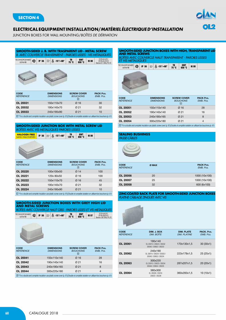
60
ELECTRICAL EQUIPMENT INSTALLATION/MATÉRIEL ÉLECTRIQUE D’INSTALLATION
CATALOGUE 2018
SECTION 4
JUNCTION bOxES fOR WALL MOUNTING/BOÎtES DE DéRivatiON
SMootH-Sided jUnction BoXeS WitH Grey HiGH Lid and MetaL ScreWSBOîTEs AVEC COUVERCLE HAUT GRIs - PAROIEs LIssEs ET VIs METALLIQUEsTECHNOPOLYMER
UL94-HB IP 56 -15°/ +60° TB75 °C
GWT 650 °C IK 07
CEI EN 60670-1CEI EN 60670-22
Directive: LVD 2006/95/CE*
Zinc-coated BacK PLate for SMootH-Sided jUnction BoXeS PLATINE CÂBLAGE ZINGUéE AVEC VIs
SeaLinG BUSHinGSPAssE-CÂBLEs
CODERÉFÉRENCE
Dim. J. bOxdiM. BoîtE
Dim. PlAtEdiM. PLAtiNE
PACK. Pcs.EMB. Pcs.
Ol 20061190x140
OL 20013 / 20023 / 20032 20042 / 20052 / 20223
170x130x1,5 30 (30x1)
Ol 20062240x190
OL 20014 / 20024 / 20033 /20043 / 20053 / 20224
223x178x1,5 25 (25x1)
Ol 20063300x220
OL 20015 / 20025 / 2003420044 / 20054 / 20225
287x207x1,5 20 (20x1)
Ol 20064380x300
OL 20026 / 20016 20035 / 20226
360x283x1,5 10 (10x1)
CODERÉFÉRENCE
Ø mAx PACK Pcs.EMB. Pcs.
Ol 20056 20 1000 (10x100)
Ol 20057 25 1000 (10x100)
Ol 20058 32 600 (6x100)
CODERÉFÉRENCE
DimEnSiOnSdiMENsioNs
SCREW COVERBouChoNs
PACK Pcs.EMB. Pcs.
Ol 20041 150x110x140 Ø 16 28
Ol 20042 190x140x140 Ø 21 16
Ol 20043 240x190x165 Ø 21 8
Ol 20044 300x220x180 Ø 21 4
* For a double and complete insulation use plastic screw cover (p. 61)/Double et complète isolation en utilisant les bouchons (p. 61)
SMootH-Sided j. B. WitH traSParent Lid - MetaL ScreWB. AVEC COUVERCLE TRANsPARENT - PAROIEs LIssEs - VIs METALLIQUEsTECHNOPOLYMER
UL94-HB IP 56 -15°/ +60° TB75 °C
GWT 650 °C IK 08
CEI EN 60 670-1CEI EN 60 670-22
Directive B.T. 2006/95/CE
CODERÉFÉRENCE
DimEnSiOnSdiMENsioNs
SCREW COVERBouChoNs
PACK Pcs.EMB. Pcs.
Ol 20031 150x110x70 Ø 16 30
Ol 20032 190x140x70 Ø 21 32
Ol 20033 240x190x90 Ø 21 10
* For a double and complete insulation use plastic screw cover (p. 61)/Double et complète isolation en utilisant les bouchons (p. 61)
*
SMootH-Sided jUnction BoX WitH MetaL ScreW LidBOîTEs AVEC VIs METALLIQUEs PAROIEs LIssEsHALOGEN FREEsAns HALogenes IP 56 -15°/ +60° TB
120 °CGWT
850 °C IK 08
CODERÉFÉRENCE
DimEnSiOnSdiMENsioNs
SCREW COVERBouChoNs
PACK Pcs.EMB. Pcs.
Ol 20220 100x100x50 Ø 14 100
Ol 20221 120x 80x50 Ø 16 100
Ol 20222 150x110x70 Ø 16 45
Ol 20223 190x140x70 Ø 21 32
Ol 20224 240x190x90 Ø 21 10
* For a double and complete insulation use plastic screw cover (p. 61)/Double et complète isolation en utilisant les bouchons (p. 61)
*
SMootH-Sided jUnction BoXeS WitH HiGH, tranSParent Lid and MetaL ScreWSBOîTEs AVEC COUVERCLE HAUT TRANsPARENT - PAROIEs LIssEs ET VIs METALLIQUEsTECHNOPOLYMER
UL94-HB IP 56 -15°/ +60° TB75 °C
GWT 650 °C IK 08
CODERÉFÉRENCE
DimEnSiOnSdiMENsioNs
SCREW COVERBouChoNs
PACK Pcs.EMB. Pcs.
Ol 20051 150x110x140 Ø 16 28
Ol 20052 190x140x140 Ø 21 16
Ol 20053 240x190x165 Ø 21 8
Ol 20054 300x220x180 Ø 21 4
* For a double and complete insulation use plastic screw cover (p. 61)/Double et complète isolation en utilisant les bouchons (p. 61)
*
OL2
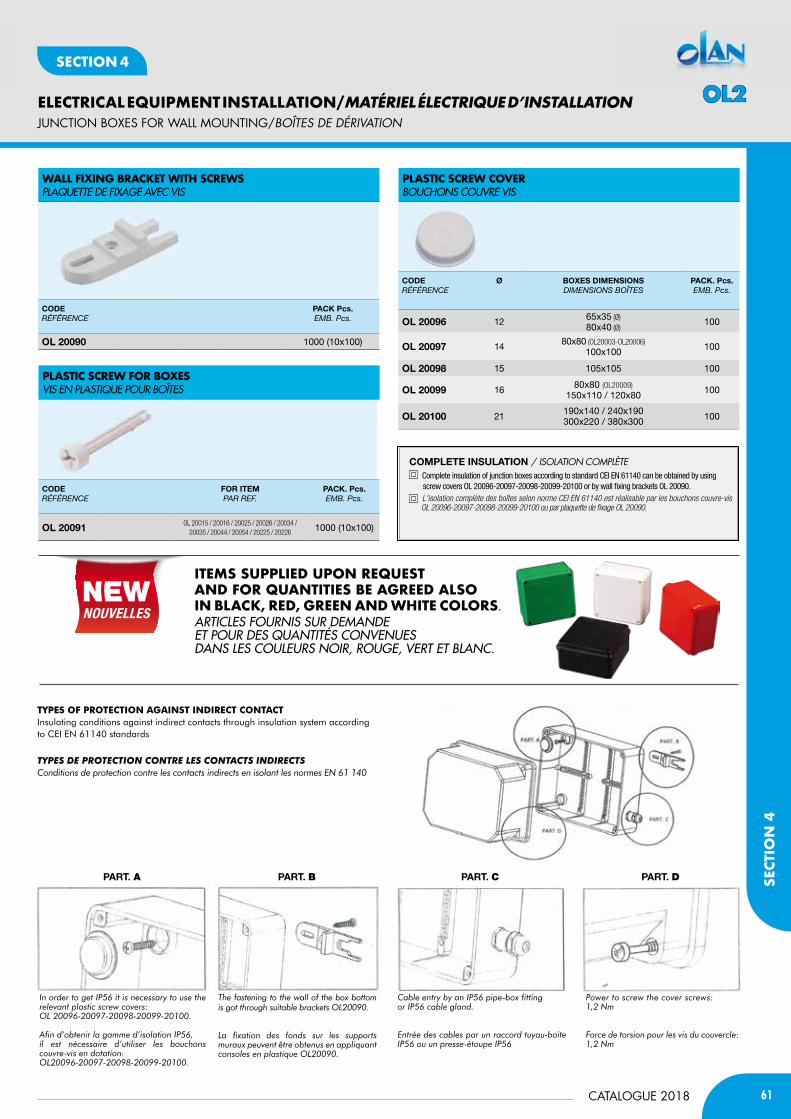
61CATALOGUE 2018
ELECTRICAL EQUIPMENT INSTALLATION/MATÉRIEL ÉLECTRIQUE D’INSTALLATION
SECT
ION
4
SECTION 4
TypEs OF pROTEcTiON AGAiNsT iNdiREcT cONTAcTInsulating conditions against indirect contacts through insulation system accordingto cEI EN 61140 standards
Types de proTecTion conTre les conTacTs indirecTsconditions de protection contre les contacts indirects en isolant les normes en 61 140
in order to get ip56 it is necessary to use the relevant plastic screw covers:oL 20096-20097-20098-20099-20100.
Afin d’obtenir la gamme d’isolation ip56, il est nécessaire d’utiliser les bouchons couvre-vis en dotation:oL20096-20097-20098-20099-20100.
cable entry by an ip56 pipe-box fittingor ip56 cable gland.
entrée des cables par un raccord tuyau-boite ip56 ou un presse-étoupe ip56
power to screw the cover screws:1,2 nm
force de torsion pour les vis du couvercle: 1,2 nm
the fastening to the wall of the box bottom is got through suitable brackets oL20090.
La fixation des fonds sur les supports muraux peuvent être obtenus en appliquant consoles en plastique oL20090.
PARt. A PARt. C PARt. DPARt. B
JUNCTION bOxES fOR WALL MOUNTING/BOÎtES DE DéRivatiON
CODERÉFÉRENCE
PACK Pcs.EMB. Pcs.
Ol 20090 1000 (10x100)
CODERÉFÉRENCE
FOR itEmPAR REF.
PACK. Pcs.EMB. Pcs.
Ol 20091 OL 20015 / 20016 / 20025 / 20026 / 20034 / 20035 / 20044 / 20054 / 20225 / 20226 1000 (10x100)
CODERÉFÉRENCE
Ø bOxES DimEnSiOnSdiMENsioNs BoîtEs
PACK. Pcs.EMB. Pcs.
Ol 20096 12 65x35 (Ø)80x40 (Ø)
100
Ol 20097 14 80x80 (OL20003-OL20006)100x100 100
Ol 20098 15 105x105 100
Ol 20099 16 80x80 (OL20009)150x110 / 120x80 100
Ol 20100 21 190x140 / 240x190300x220 / 380x300 100
WaLL fiXinG BracKet WitH ScreWSPLAQUETTE DE FIXAGE AVEC VIs
PLaStic ScreW for BoXeSVIs EN PLAsTIQUE POUR BOîTEs
PLaStic ScreW coverBOUCHONs COUVRE VIs
COmPlEtE inSUlAtiOn / iSOlaTiOn cOmplèTE Complete insulation of junction boxes according to standard CEI EN 61140 can be obtained by using screw covers OL 20096-20097-20098-20099-20100 or by wall fixing brackets OL 20090. L'isolation complète des boîtes selon norme CEI EN 61140 est réalisable par les bouchons couvre-vis OL 20096-20097-20098-20099-20100 ou par plaquette de fixage OL 20090.
iteMS SUPPLied UPon reQUeSt and for QUantitieS Be aGreed aLSo in BLacK, red, Green and WHite coLorS.ARTICLEs FOURNIs sUR DEMANDE ET POUR DEs QUANTITés CONVENUEs DANs LEs COULEURs NOIR, ROUGE, VERT ET BLANC.
OL2
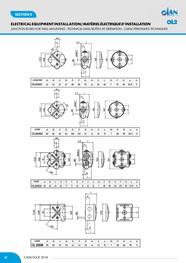
62
ELECTRICAL EQUIPMENT INSTALLATION/MATÉRIEL ÉLECTRIQUE D’INSTALLATION
CATALOGUE 2018
SECTION 4
CODE/REF
CODE
CODE
CODE
JUNCTION bOxES fOR WALL MOUNTING - TECHNICAL DATA/BOÎtES DE DéRivatiON - caRactéRiStiQUES tEcHNiQUES
OL2
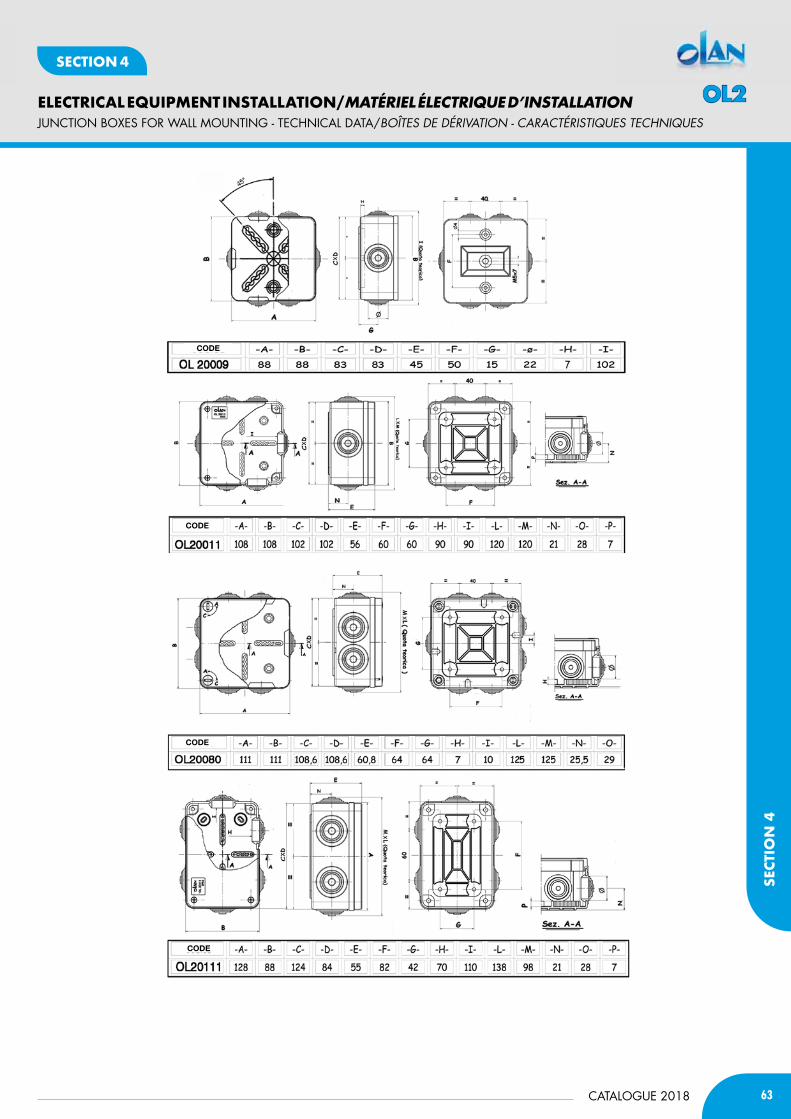
63CATALOGUE 2018
ELECTRICAL EQUIPMENT INSTALLATION/MATÉRIEL ÉLECTRIQUE D’INSTALLATION
SECT
ION
4
SECTION 4
CODE
CODE
CODE
CODE
JUNCTION bOxES fOR WALL MOUNTING - TECHNICAL DATA/BOÎtES DE DéRivatiON - caRactéRiStiQUES tEcHNiQUES
OL2

64
ELECTRICAL EQUIPMENT INSTALLATION/MATÉRIEL ÉLECTRIQUE D’INSTALLATION
CATALOGUE 2018
SECTION 4
CODE
CODE
CODE
CODE
JUNCTION bOxES fOR WALL MOUNTING - TECHNICAL DATA/BOÎtES DE DéRivatiON - caRactéRiStiQUES tEcHNiQUES
OL2

65CATALOGUE 2018
ELECTRICAL EQUIPMENT INSTALLATION/MATÉRIEL ÉLECTRIQUE D’INSTALLATION
SECT
ION
4
SECTION 4
CODE
CODE
CODE
CODE
JUNCTION bOxES fOR WALL MOUNTING - TECHNICAL DATA/BOÎtES DE DéRivatiON - caRactéRiStiQUES tEcHNiQUES
OL2
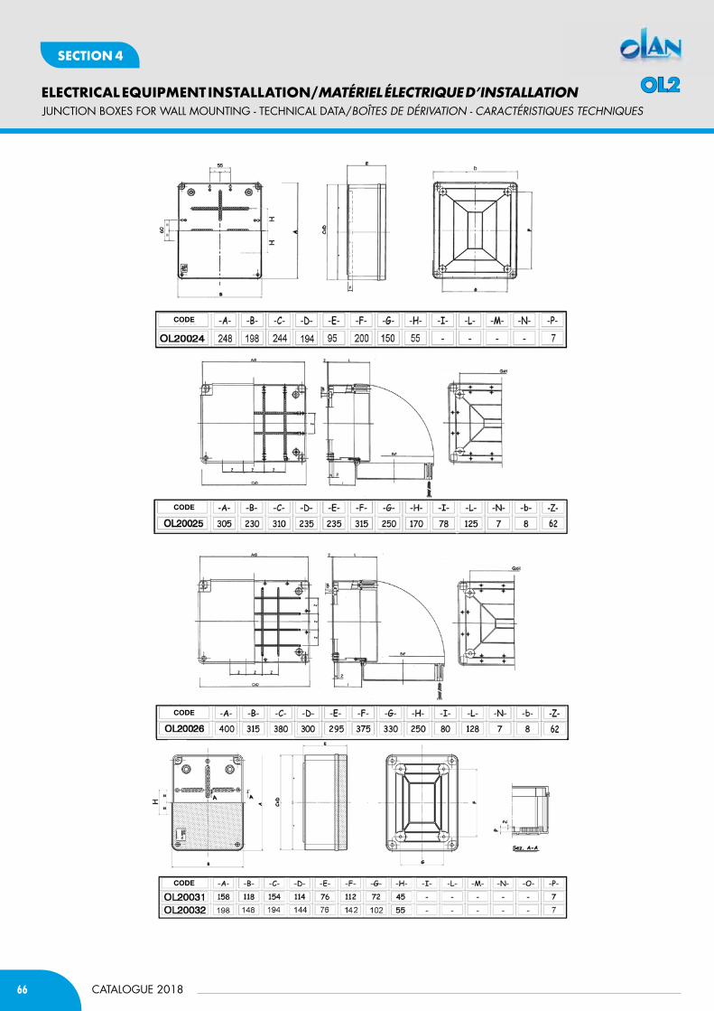
66
ELECTRICAL EQUIPMENT INSTALLATION/MATÉRIEL ÉLECTRIQUE D’INSTALLATION
CATALOGUE 2018
SECTION 4
CODE
CODE
CODE
CODE
JUNCTION bOxES fOR WALL MOUNTING - TECHNICAL DATA/BOÎtES DE DéRivatiON - caRactéRiStiQUES tEcHNiQUES
OL2
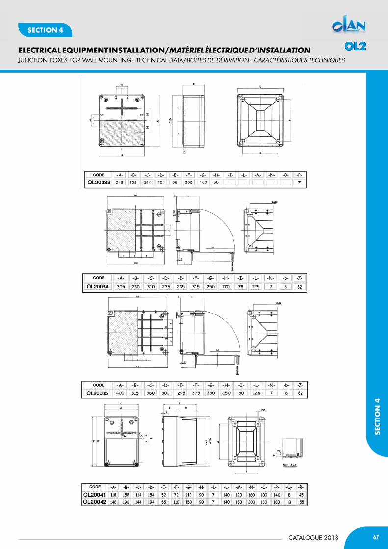
67CATALOGUE 2018
ELECTRICAL EQUIPMENT INSTALLATION/MATÉRIEL ÉLECTRIQUE D’INSTALLATION
SECT
ION
4
SECTION 4
CODE
CODE
CODE
CODE
JUNCTION bOxES fOR WALL MOUNTING - TECHNICAL DATA/BOÎtES DE DéRivatiON - caRactéRiStiQUES tEcHNiQUES
OL2
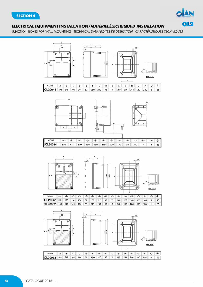
68
ELECTRICAL EQUIPMENT INSTALLATION/MATÉRIEL ÉLECTRIQUE D’INSTALLATION
CATALOGUE 2018
SECTION 4
CODE
CODE
CODE
CODE
JUNCTION bOxES fOR WALL MOUNTING - TECHNICAL DATA/BOÎtES DE DéRivatiON - caRactéRiStiQUES tEcHNiQUES
OL2
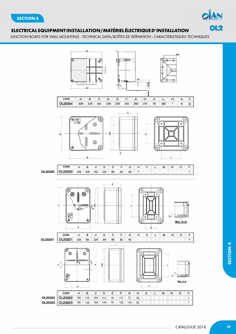
69CATALOGUE 2018
ELECTRICAL EQUIPMENT INSTALLATION/MATÉRIEL ÉLECTRIQUE D’INSTALLATION
SECT
ION
4
SECTION 4
Ol20320
Ol20321
Ol20322
Ol20323
CODE
CODE
CODE
CODE
JUNCTION bOxES fOR WALL MOUNTING - TECHNICAL DATA/BOÎtES DE DéRivatiON - caRactéRiStiQUES tEcHNiQUES
OL2

70
ELECTRICAL EQUIPMENT INSTALLATION/MATÉRIEL ÉLECTRIQUE D’INSTALLATION
CATALOGUE 2018
SECTION 4
Ol20324
Ol20325
Ol20326
CODE
CODE
CODE
CODE
JUNCTION bOxES fOR WALL MOUNTING - TECHNICAL DATA/BOÎtES DE DéRivatiON - caRactéRiStiQUES tEcHNiQUES
OL2
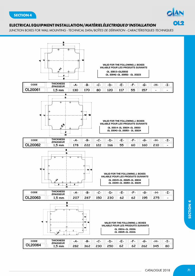
71CATALOGUE 2018
ELECTRICAL EQUIPMENT INSTALLATION/MATÉRIEL ÉLECTRIQUE D’INSTALLATION
SECT
ION
4
SECTION 4
CODE
CODE
CODE
CODE
tHiCKnESSéPaiSSEUr
tHiCKnESSéPaiSSEUr
tHiCKnESSéPaiSSEUr
tHiCKnESSéPaiSSEUr
VAliD FOR tHE FOllOWinG J. bOxESvaLaBLE POUr LES PrOdUiTS SUivanTS
VAliD FOR tHE FOllOWinG J. bOxESvaLaBLE POUr LES PrOdUiTS SUivanTS
VAliD FOR tHE FOllOWinG J. bOxESvaLaBLE POUr LES PrOdUiTS SUivanTS
VAliD FOR tHE FOllOWinG J. bOxESvaLaBLE POUr LES PrOdUiTS SUivanTS
JUNCTION bOxES fOR WALL MOUNTING - TECHNICAL DATA/BOÎtES DE DéRivatiON - caRactéRiStiQUES tEcHNiQUES
OL2
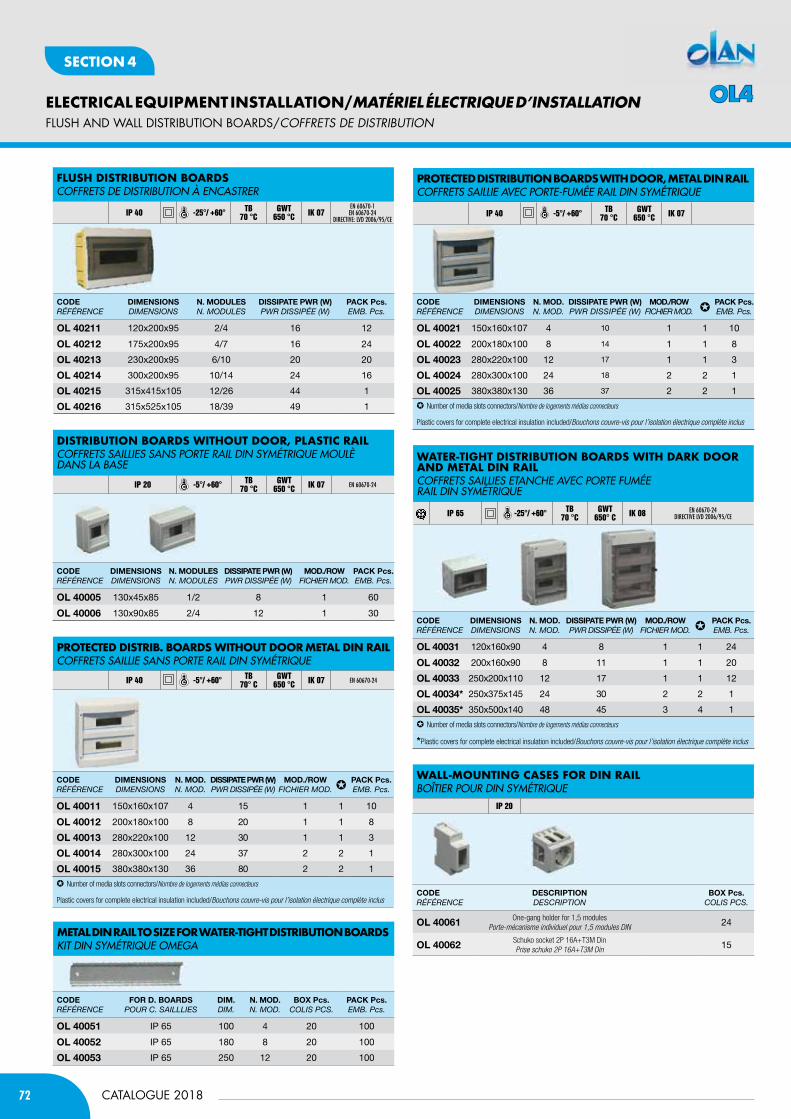
72
ELECTRICAL EQUIPMENT INSTALLATION/MATÉRIEL ÉLECTRIQUE D’INSTALLATION
CATALOGUE 2018
SECTION 4
fLUSH AND WALL DISTRIbUTION bOARDS/cOffREtS DE DiStRiBUtiON
MetaL din raiL to SiZe for Water-tiGHt diStriBUtion BoardSKIT DIN syMéTRIQUE OMEGA
CODERÉFÉRENCE
DimEnSiOnSdiMENsioNs
n. mODUlESN. ModuLEs
DiSSiPAtE PWR (W)PWR dissiPÉE (W)
PACK Pcs.EMB. Pcs.
Ol 40211 120x200x95 2/4 16 12
Ol 40212 175x200x95 4/7 16 24
Ol 40213 230x200x95 6/10 20 20
Ol 40214 300x200x95 10/14 24 16
Ol 40215 315x415x105 12/26 44 1
Ol 40216 315x525x105 18/39 49 1
CODERÉFÉRENCE
DimEnSiOnSdiMENsioNs
n. mOD.N. Mod.
DiSSiPAtE PWR (W)PWR dissiPÉE (W)
mOD./ROWFiChiER Mod. ✪
PACK Pcs.EMB. Pcs.
Ol 40011 150x160x107 4 15 1 1 10
Ol 40012 200x180x100 8 20 1 1 8
Ol 40013 280x220x100 12 30 1 1 3
Ol 40014 280x300x100 24 37 2 2 1
Ol 40015 380x380x130 36 80 2 2 1
✪ Number of media slots connectors/Nombre de logements médias connecteurs
Plastic covers for complete electrical insulation included/Bouchons couvre-vis pour l’isolation électrique complète inclus
CODERÉFÉRENCE
DimEnSiOnSdiMENsioNs
n. mOD.N. Mod.
DiSSiPAtE PWR (W)PWR dissiPÉE (W)
mOD./ROWFiChiER Mod. ✪
PACK Pcs.EMB. Pcs.
Ol 40021 150x160x107 4 10 1 1 10
Ol 40022 200x180x100 8 14 1 1 8
Ol 40023 280x220x100 12 17 1 1 3
Ol 40024 280x300x100 24 18 2 2 1
Ol 40025 380x380x130 36 37 2 2 1
✪ Number of media slots connectors/Nombre de logements médias connecteurs
Plastic covers for complete electrical insulation included/Bouchons couvre-vis pour l’isolation électrique complète inclus
CODERÉFÉRENCE
DimEnSiOnSdiMENsioNs
n. mOD.N. Mod.
DiSSiPAtE PWR (W)PWR dissiPÉE (W)
mOD./ROWFiChiER Mod. ✪
PACK Pcs.EMB. Pcs.
Ol 40031 120x160x90 4 8 1 1 24
Ol 40032 200x160x90 8 11 1 1 20
Ol 40033 250x200x110 12 17 1 1 12
Ol 40034* 250x375x145 24 30 2 2 1
Ol 40035* 350x500x140 48 45 3 4 1
✪ Number of media slots connectors/Nombre de logements médias connecteurs
*Plastic covers for complete electrical insulation included/Bouchons couvre-vis pour l’isolation électrique complète inclus
CODERÉFÉRENCE
FOR D. bOARDSPouR C. sAiLLLiEs
Dim.diM.
n. mOD.N. Mod.
bOx Pcs.CoLis PCs.
PACK Pcs.EMB. Pcs.
Ol 40051 IP 65 100 4 20 100
Ol 40052 IP 65 180 8 20 100
Ol 40053 IP 65 250 12 20 100
CODERÉFÉRENCE
DimEnSiOnSdiMENsioNs
n. mODUlESN. ModuLEs
DiSSiPAtE PWR (W)PWR dissiPÉE (W)
mOD./ROWFiChiER Mod.
PACK Pcs.EMB. Pcs.
Ol 40005 130x45x85 1/2 8 1 60
Ol 40006 130x90x85 2/4 12 1 30
diStriBUtion BoardS WitHoUt door, PLaStic raiL COFFRETs sAILLIEs sANs PORTE RAIL DIN syMéTRIQUE MOULè DANs LA BAsE
IP 20 -5°/ +60° TB 70 °C
GWT 650 °C IK 07 EN 60670-24
Protected diStriB. BoardS WitHoUt door MetaL din raiLCOFFRETs sAILLIE sANs PORTE RAIL DIN syMéTRIQUE
IP 40 -5°/ +60° TB70° C
GWT650 °C IK 07 EN 60670-24
Protected diStriBUtion BoardS WitH door, MetaL din raiLCOFFRETs sAILLIE AVEC PORTE-FUMéE RAIL DIN syMéTRIQUE
IP 40 -5°/ +60° TB 70 °C
GWT 650 °C IK 07
Water-tiGHt diStriBUtion BoardS WitH darK door and MetaL din raiLCOFFRETs sAILLIEs ETANCHE AVEC PORTE FUMéE RAIL DIN syMéTRIQUE
IP 65 -25°/ +60° TB70 °C
GWT650° C IK 08 EN 60670-24
DIRECTIVE lVD 2006/95/CE
WaLL-MoUntinG caSeS for din raiLBOîTIER POUR DIN syMéTRIQUE
IP 20
CODERÉFÉRENCE
DESCRiPtiOndEsCRiPtioN
bOx Pcs.CoLis PCs.
Ol 40061 One-gang holder for 1,5 modulesPorte-mécanisme individuel pour 1,5 modules DIN 24
Ol 40062 Schuko socket 2P 16A+T3M DinPrise schuko 2P 16A+T3M Din 15
fLUSH diStriBUtion BoardS COFFRETs DE DIsTRIBUTION à ENCAsTRER
IP 40 -25°/ +60° TB 70 °C
GWT 650 °C IK 07
EN 60670-1 EN 60670-24
DIRECTIVE: lVD 2006/95/CE
OL4
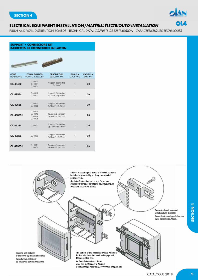
73CATALOGUE 2018
ELECTRICAL EQUIPMENT INSTALLATION/MATÉRIEL ÉLECTRIQUE D’INSTALLATION
SECT
ION
4
SECTION 4
SUPPort + connectorS KitBarretteS de conneXion en Laiton
CODERÉFÉRENCE
FOR D. bOARDSPouR C. sAiLLLiEs
DESCRiPtiOndEsCRiPtioN
bOx Pcs.CoLis PCs.
PACK Pcs.EMB. Pcs.
Ol 49482OL 40011OL 40021OL 40031
1 support, 2 connectors 5p-10mm2 1 20
Ol 49584 OL 40012OL 40022
1 support, 2 connectors 2p-16mm2+8p-10mm2 1 20
Ol 49685 OL 40013OL 40023
1 support, 2 connectors 2p-16mm2+12p-10mm2 1 20
Ol 496851
OL 40014OL 40015OL 40024OL 40025
2 supports, 2 connectors 2p-16mm2+12p-10mm2 1 20
Ol 49284 OL 400321 support, 2 connectors 2p-16mm2+8p-10mm2 1 20
Ol 49385 OL 400331 support, 2 connectors 2p-16mm2+12p-10mm2 1 20
Ol 493851 OL 40034OL 40035
2 supports, 4 connectors 2p-16mm2+12p-10mm2 1 20
Subject to securing the boxes to the wall, complete isolation is achieved by applying the supplied screw covers.Après la fixation du fond de la boîte au mur, l’isolement complet est obtenu en appliquant les bouchons couvre-vis fournis.
Opening and isolation of the cover by means of screws.Ouverture et isolementdu couvercle par vis de fixation.
The bottom of the boxes is provided with rails for the attachment of electrical equipment,fittings, plates, etc..Le fond de la boite est fourni avec des guides pour la fixation d’appareillage électrique, accessoires, plaques, etc.
Example of wall mounted with brackets OL20090.Exemple de montage fixé au mur avec consoles OL20090.
fLUSH AND WALL DISTRIbUTION bOARDS - TECHNICAL DATA/cOffREtS DE DiStRiBUtiON - caRactéRiStiQUES tEcHNiQUES
OL4

74
ELECTRICAL EQUIPMENT INSTALLATION/MATÉRIEL ÉLECTRIQUE D’INSTALLATION
CATALOGUE 2018
SECTION 4
Prepared for fixing door with security screw.
Préparation pour la fixation de la porte avec la vis de sécurité.
Knockout holes for input and output.Trous pour entrée et sortie.
Possibility of housing terminal T + N connectors on both ends.Possibilité de logement terminal T + N sur les deux extrémités.
Prepared for Base + Door sealing.Préparation de base + joint de la porte.
Possibility of fastening the enclosures on the outside.Possibilité de fixer les tableaux à l’extérieur.
Insulated plastic screws.Vis isolées en plastique.
Prepared for fixing the DIN rail at three levels of height.
Préparation pour la fixation à trois niveaux de hauteur du rail DIN.
Insulating covers.Capuchons isolants.
fLUSH AND WALL DISTRIbUTION bOARDS - TECHNICAL DATA/cOffREtS DE DiStRiBUtiON - caRactéRiStiQUES tEcHNiQUES
OL4

75CATALOGUE 2018
ELECTRICAL EQUIPMENT INSTALLATION/MATÉRIEL ÉLECTRIQUE D’INSTALLATION
SECT
ION
4
SECTION 4
fLUSH AND WALL DISTRIbUTION bOARDS - TECHNICAL DATA/cOffREtS DE DiStRiBUtiON - caRactéRiStiQUES tEcHNiQUES
CODE
CODE
CODE
CODE
OL4

76
ELECTRICAL EQUIPMENT INSTALLATION/MATÉRIEL ÉLECTRIQUE D’INSTALLATION
CATALOGUE 2018
SECTION 4
CODE
CODE
CODE
CODE
fLUSH AND WALL DISTRIbUTION bOARDS - TECHNICAL DATA/cOffREtS DE DiStRiBUtiON - caRactéRiStiQUES tEcHNiQUES
OL4
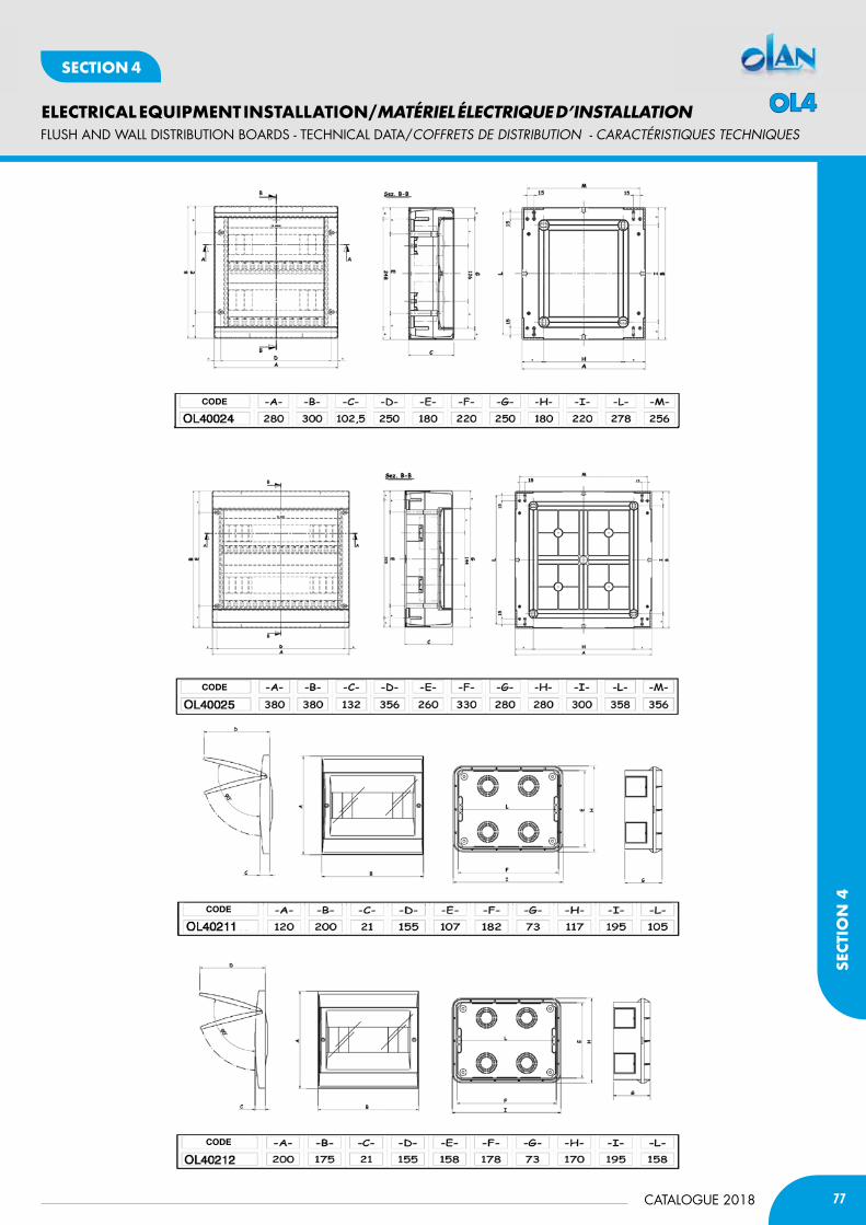
77CATALOGUE 2018
ELECTRICAL EQUIPMENT INSTALLATION/MATÉRIEL ÉLECTRIQUE D’INSTALLATION
SECT
ION
4
SECTION 4
CODE
CODE
CODE
CODE
fLUSH AND WALL DISTRIbUTION bOARDS - TECHNICAL DATA/cOffREtS DE DiStRiBUtiON - caRactéRiStiQUES tEcHNiQUES
OL4
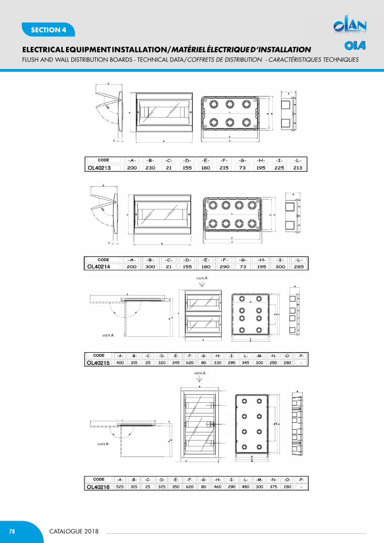
78
ELECTRICAL EQUIPMENT INSTALLATION/MATÉRIEL ÉLECTRIQUE D’INSTALLATION
CATALOGUE 2018
SECTION 4
CODE
CODE
CODE
CODE
fLUSH AND WALL DISTRIbUTION bOARDS - TECHNICAL DATA/cOffREtS DE DiStRiBUtiON - caRactéRiStiQUES tEcHNiQUES
OL4
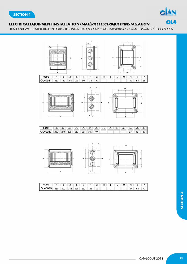
79CATALOGUE 2018
ELECTRICAL EQUIPMENT INSTALLATION/MATÉRIEL ÉLECTRIQUE D’INSTALLATION
SECT
ION
4
SECTION 4
CODE
CODE
CODE
fLUSH AND WALL DISTRIbUTION bOARDS - TECHNICAL DATA/cOffREtS DE DiStRiBUtiON - caRactéRiStiQUES tEcHNiQUES
OL4
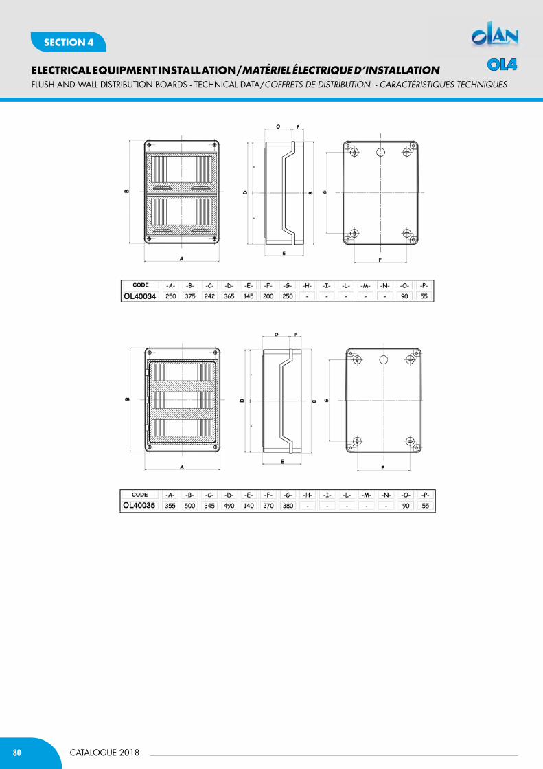
80
ELECTRICAL EQUIPMENT INSTALLATION/MATÉRIEL ÉLECTRIQUE D’INSTALLATION
CATALOGUE 2018
SECTION 4
CODE
CODE
fLUSH AND WALL DISTRIbUTION bOARDS - TECHNICAL DATA/cOffREtS DE DiStRiBUtiON - caRactéRiStiQUES tEcHNiQUES
OL4
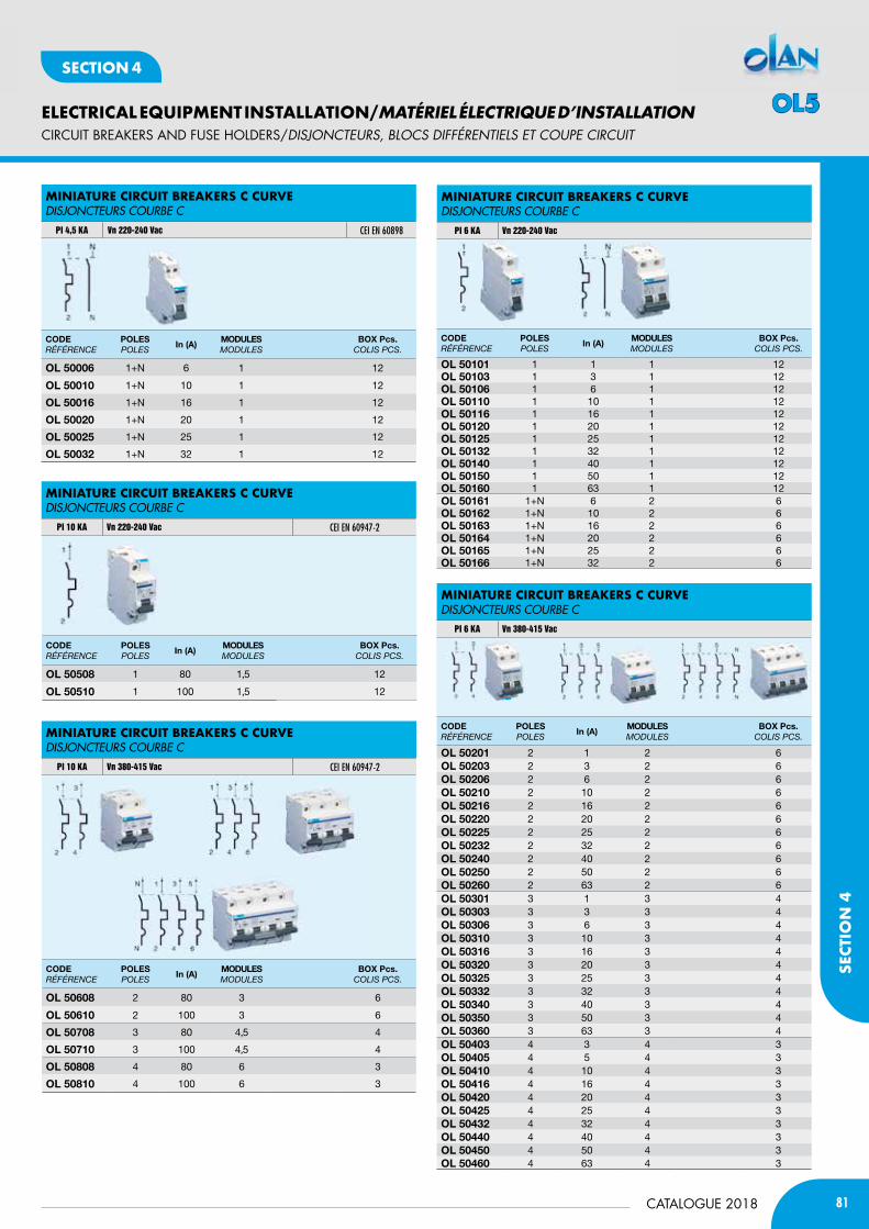
81CATALOGUE 2018
ELECTRICAL EQUIPMENT INSTALLATION/MATÉRIEL ÉLECTRIQUE D’INSTALLATION
SECT
ION
4
SECTION 4
CIRCUIT bREAKERS AND fUSE HOLDERS/DiSjONctEURS, BLOcS DifféRENtiELS Et cOUpE ciRcUit
MiniatUre circUit BreaKerS c cUrveDIsJONCTEURs COURBE C
PI 4,5 KA Vn 220-240 Vac CEI EN 60898
MiniatUre circUit BreaKerS c cUrveDIsJONCTEURs COURBE C
PI 10 KA Vn 220-240 Vac CEI EN 60947-2
MiniatUre circUit BreaKerS c cUrveDIsJONCTEURs COURBE C
PI 10 KA Vn 380-415 Vac CEI EN 60947-2
CODERÉFÉRENCE
POlESPoLEs
in (A)mODUlESModuLEs
bOx Pcs.CoLis PCs.
Ol 50006 1+N 6 1 12
Ol 50010 1+N 10 1 12
Ol 50016 1+N 16 1 12
Ol 50020 1+N 20 1 12
Ol 50025 1+N 25 1 12
Ol 50032 1+N 32 1 12
CODERÉFÉRENCE
POlESPoLEs
in (A)mODUlESModuLEs
bOx Pcs.CoLis PCs.
Ol 50508 1 80 1,5 12
Ol 50510 1 100 1,5 12
CODERÉFÉRENCE
POlESPoLEs
in (A)mODUlESModuLEs
bOx Pcs.CoLis PCs.
Ol 50608 2 80 3 6
Ol 50610 2 100 3 6
Ol 50708 3 80 4,5 4
Ol 50710 3 100 4,5 4
Ol 50808 4 80 6 3
Ol 50810 4 100 6 3
CODERÉFÉRENCE
POlESPoLEs
in (A)mODUlESModuLEs
bOx Pcs.CoLis PCs.
Ol 50101 1 1 1 12Ol 50103 1 3 1 12Ol 50106 1 6 1 12Ol 50110 1 10 1 12Ol 50116 1 16 1 12Ol 50120 1 20 1 12Ol 50125 1 25 1 12Ol 50132 1 32 1 12Ol 50140 1 40 1 12Ol 50150 1 50 1 12Ol 50160 1 63 1 12Ol 50161 1+N 6 2 6Ol 50162 1+N 10 2 6Ol 50163 1+N 16 2 6Ol 50164 1+N 20 2 6Ol 50165 1+N 25 2 6Ol 50166 1+N 32 2 6
CODERÉFÉRENCE
POlESPoLEs
in (A)mODUlESModuLEs
bOx Pcs.CoLis PCs.
Ol 50201 2 1 2 6Ol 50203 2 3 2 6Ol 50206 2 6 2 6Ol 50210 2 10 2 6Ol 50216 2 16 2 6Ol 50220 2 20 2 6Ol 50225 2 25 2 6Ol 50232 2 32 2 6Ol 50240 2 40 2 6Ol 50250 2 50 2 6Ol 50260 2 63 2 6Ol 50301 3 1 3 4Ol 50303 3 3 3 4Ol 50306 3 6 3 4Ol 50310 3 10 3 4Ol 50316 3 16 3 4Ol 50320 3 20 3 4Ol 50325 3 25 3 4Ol 50332 3 32 3 4Ol 50340 3 40 3 4Ol 50350 3 50 3 4Ol 50360 3 63 3 4Ol 50403 4 3 4 3Ol 50405 4 5 4 3Ol 50410 4 10 4 3Ol 50416 4 16 4 3Ol 50420 4 20 4 3Ol 50425 4 25 4 3Ol 50432 4 32 4 3Ol 50440 4 40 4 3Ol 50450 4 50 4 3Ol 50460 4 63 4 3
MiniatUre circUit BreaKerS c cUrveDIsJONCTEURs COURBE C
PI 6 KA Vn 220-240 Vac
MiniatUre circUit BreaKerS c cUrveDIsJONCTEURs COURBE C
PI 6 KA Vn 380-415 Vac
OL5
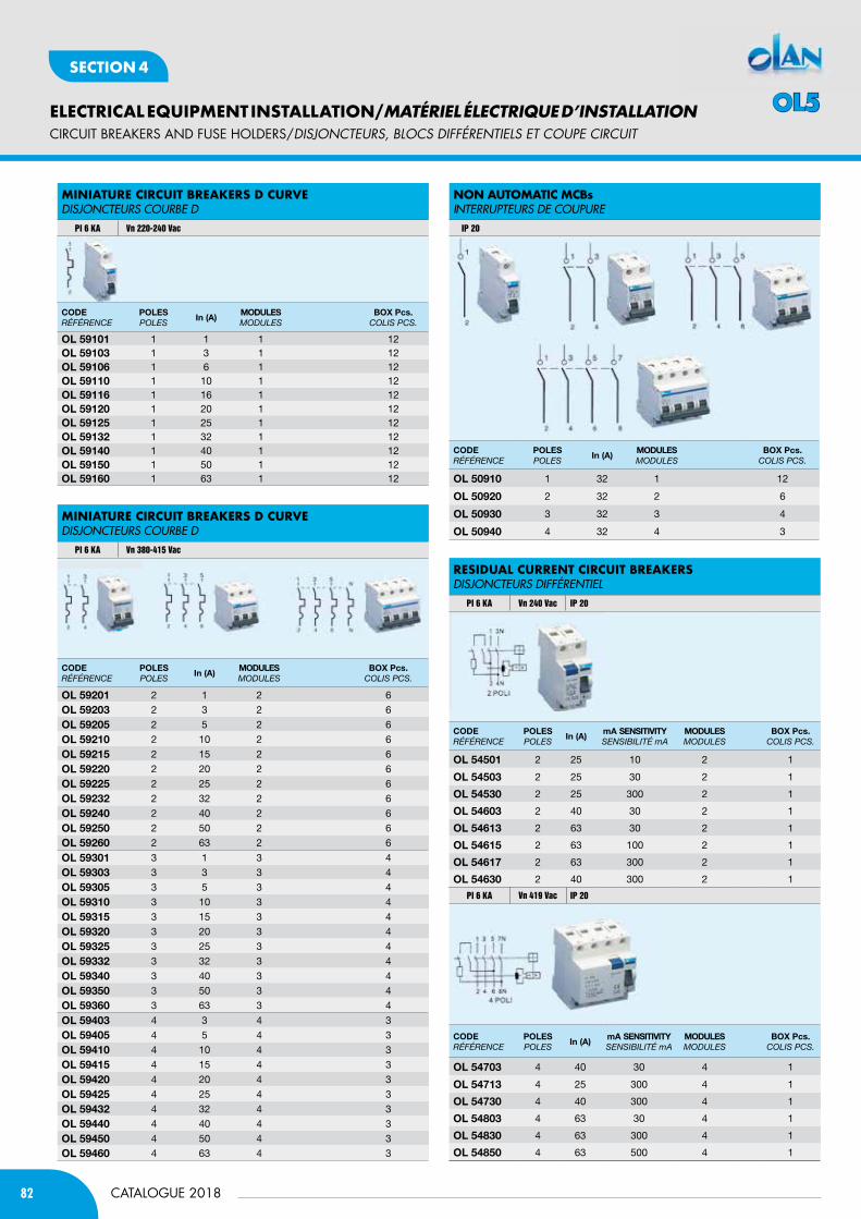
82
ELECTRICAL EQUIPMENT INSTALLATION/MATÉRIEL ÉLECTRIQUE D’INSTALLATION
CATALOGUE 2018
SECTION 4
CIRCUIT bREAKERS AND fUSE HOLDERS/DiSjONctEURS, BLOcS DifféRENtiELS Et cOUpE ciRcUit
CODERÉFÉRENCE
POlESPoLEs
in (A)mODUlESModuLEs
bOx Pcs.CoLis PCs.
Ol 59101 1 1 1 12Ol 59103 1 3 1 12Ol 59106 1 6 1 12Ol 59110 1 10 1 12Ol 59116 1 16 1 12Ol 59120 1 20 1 12Ol 59125 1 25 1 12Ol 59132 1 32 1 12Ol 59140 1 40 1 12Ol 59150 1 50 1 12Ol 59160 1 63 1 12
CODERÉFÉRENCE
POlESPoLEs
in (A)mODUlESModuLEs
bOx Pcs.CoLis PCs.
Ol 59201 2 1 2 6
Ol 59203 2 3 2 6
Ol 59205 2 5 2 6
Ol 59210 2 10 2 6
Ol 59215 2 15 2 6
Ol 59220 2 20 2 6
Ol 59225 2 25 2 6
Ol 59232 2 32 2 6
Ol 59240 2 40 2 6
Ol 59250 2 50 2 6
Ol 59260 2 63 2 6
Ol 59301 3 1 3 4
Ol 59303 3 3 3 4
Ol 59305 3 5 3 4
Ol 59310 3 10 3 4
Ol 59315 3 15 3 4
Ol 59320 3 20 3 4
Ol 59325 3 25 3 4
Ol 59332 3 32 3 4
Ol 59340 3 40 3 4
Ol 59350 3 50 3 4
Ol 59360 3 63 3 4
Ol 59403 4 3 4 3
Ol 59405 4 5 4 3
Ol 59410 4 10 4 3
Ol 59415 4 15 4 3
Ol 59420 4 20 4 3
Ol 59425 4 25 4 3
Ol 59432 4 32 4 3
Ol 59440 4 40 4 3
Ol 59450 4 50 4 3
Ol 59460 4 63 4 3
MiniatUre circUit BreaKerS d cUrve DIsJONCTEURs COURBE D
PI 6 KA Vn 220-240 Vac
MiniatUre circUit BreaKerS d cUrveDIsJONCTEURs COURBE D
PI 6 KA Vn 380-415 Vac
CODERÉFÉRENCE
POlESPoLEs
in (A)mODUlESModuLEs
bOx Pcs.CoLis PCs.
Ol 50910 1 32 1 12
Ol 50920 2 32 2 6
Ol 50930 3 32 3 4
Ol 50940 4 32 4 3
CODERÉFÉRENCE
POlESPoLEs
in (A)mA SEnSitiVitysENsiBiLitÉ mA
mODUlESModuLEs
bOx Pcs.CoLis PCs.
Ol 54501 2 25 10 2 1
Ol 54503 2 25 30 2 1
Ol 54530 2 25 300 2 1
Ol 54603 2 40 30 2 1
Ol 54613 2 63 30 2 1
Ol 54615 2 63 100 2 1
Ol 54617 2 63 300 2 1
Ol 54630 2 40 300 2 1
CODERÉFÉRENCE
POlESPoLEs
in (A)mA SEnSitiVitysENsiBiLitÉ mA
mODUlESModuLEs
bOx Pcs.CoLis PCs.
Ol 54703 4 40 30 4 1
Ol 54713 4 25 300 4 1
Ol 54730 4 40 300 4 1
Ol 54803 4 63 30 4 1
Ol 54830 4 63 300 4 1
Ol 54850 4 63 500 4 1
non aUtoMatic McBsINTERRUPTEURs DE COUPURE
IP 20
reSidUaL cUrrent circUit BreaKerSDIsJONCTEURs DIFFéRENTIEL
PI 6 KA Vn 240 Vac IP 20
PI 6 KA Vn 419 Vac IP 20
OL5
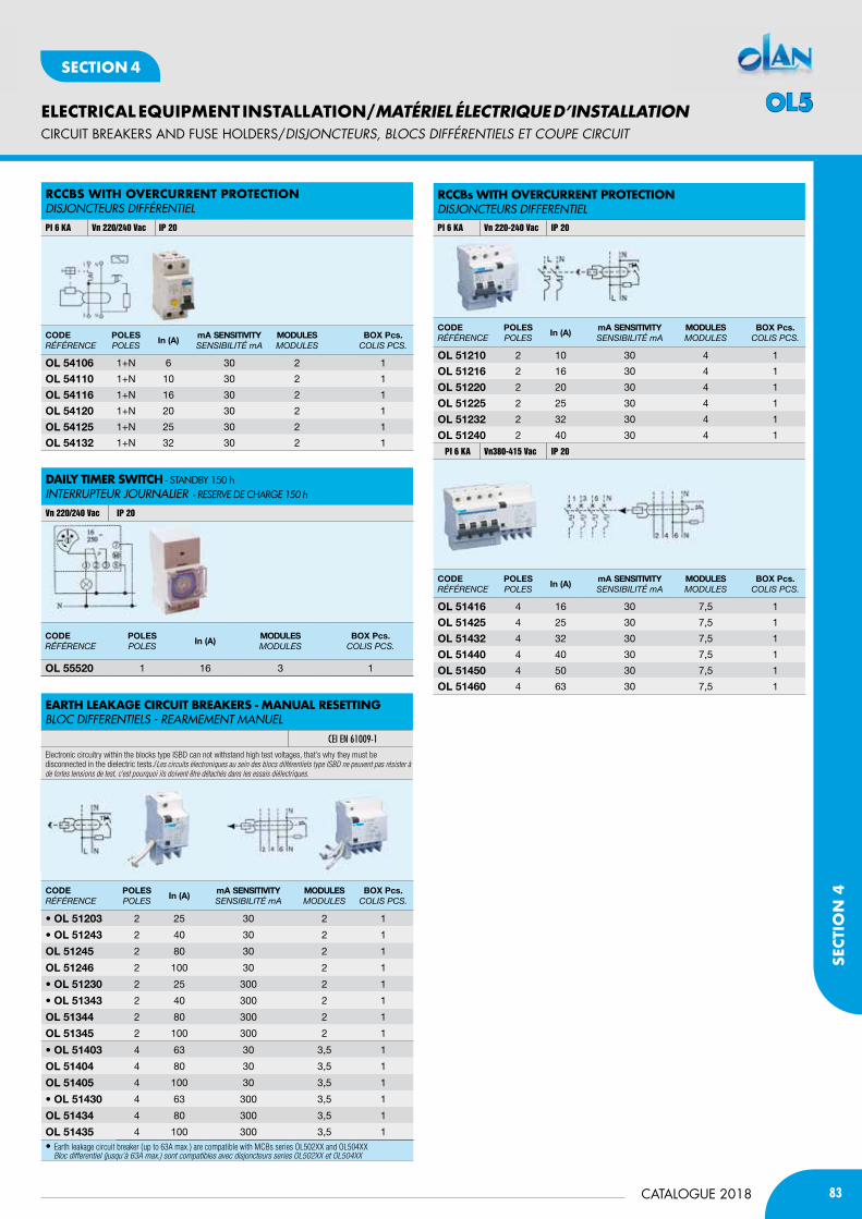
83CATALOGUE 2018
ELECTRICAL EQUIPMENT INSTALLATION/MATÉRIEL ÉLECTRIQUE D’INSTALLATION
SECT
ION
4
SECTION 4
CIRCUIT bREAKERS AND fUSE HOLDERS/DiSjONctEURS, BLOcS DifféRENtiELS Et cOUpE ciRcUit
CODERÉFÉRENCE
POlESPoLEs
in (A)mA SEnSitiVitysENsiBiLitÉ mA
mODUlESModuLEs
bOx Pcs.CoLis PCs.
Ol 54106 1+N 6 30 2 1
Ol 54110 1+N 10 30 2 1
Ol 54116 1+N 16 30 2 1
Ol 54120 1+N 20 30 2 1
Ol 54125 1+N 25 30 2 1
Ol 54132 1+N 32 30 2 1
CODERÉFÉRENCE
POlESPoLEs
in (A)mODUlESModuLEs
bOx Pcs.CoLis PCs.
Ol 55520 1 16 3 1
rccBS WitH overcUrrent ProtectionDIsJONCTEURs DIFFéRENTIEL
PI 6 KA Vn 220/240 Vac IP 20
daiLy tiMer SWitcH - STaNDbY 150 h INTERRUPTEUR JOURNALIER - reserve de cHArge 150 h
Vn 220/240 Vac IP 20
CODERÉFÉRENCE
POlESPoLEs
in (A)mA SEnSitiVitysENsiBiLitÉ mA
mODUlESModuLEs
bOx Pcs.CoLis PCs.
Ol 51210 2 10 30 4 1
Ol 51216 2 16 30 4 1
Ol 51220 2 20 30 4 1
Ol 51225 2 25 30 4 1
Ol 51232 2 32 30 4 1
Ol 51240 2 40 30 4 1
CODERÉFÉRENCE
POlESPoLEs
in (A)mA SEnSitiVitysENsiBiLitÉ mA
mODUlESModuLEs
bOx Pcs.CoLis PCs.
Ol 51416 4 16 30 7,5 1
Ol 51425 4 25 30 7,5 1
Ol 51432 4 32 30 7,5 1
Ol 51440 4 40 30 7,5 1
Ol 51450 4 50 30 7,5 1
Ol 51460 4 63 30 7,5 1
CODERÉFÉRENCE
POlESPoLEs
in (A)mA SEnSitiVitysENsiBiLitÉ mA
mODUlESModuLEs
bOx Pcs.CoLis PCs.
• Ol 51203 2 25 30 2 1
• Ol 51243 2 40 30 2 1
Ol 51245 2 80 30 2 1
Ol 51246 2 100 30 2 1
• Ol 51230 2 25 300 2 1
• Ol 51343 2 40 300 2 1
Ol 51344 2 80 300 2 1
Ol 51345 2 100 300 2 1
• Ol 51403 4 63 30 3,5 1
Ol 51404 4 80 30 3,5 1
Ol 51405 4 100 30 3,5 1
• Ol 51430 4 63 300 3,5 1
Ol 51434 4 80 300 3,5 1
Ol 51435 4 100 300 3,5 1 • Earth leakage circuit breaker (up to 63A max.) are compatible with MCBs series OL502XX and OL504XX Bloc differentiel (jusqu’à 63A max.) sont compatibles avec disjoncteurs series OL502XX et OL504XX
PI 6 KA Vn380-415 Vac IP 20
rccBs WitH overcUrrent Protection DIsJONCTEURs DIFFERENTIELPI 6 KA Vn 220-240 Vac IP 20
eartH LeaKaGe circUit BreaKerS - ManUaL reSettinGBLOC DIFFERENTIELs - REARMEMENT MANUEL
CEI EN 61009-1
Electronic circuitry within the blocks type ISBD can not withstand high test voltages, that’s why they must be disconnected in the dielectric tests./Les circuits électroniques au sein des blocs différentiels type ISBD ne peuvent pas résister à de fortes tensions de test, c’est pourquoi ils doivent être détachés dans les essais diélectriques.
OL5
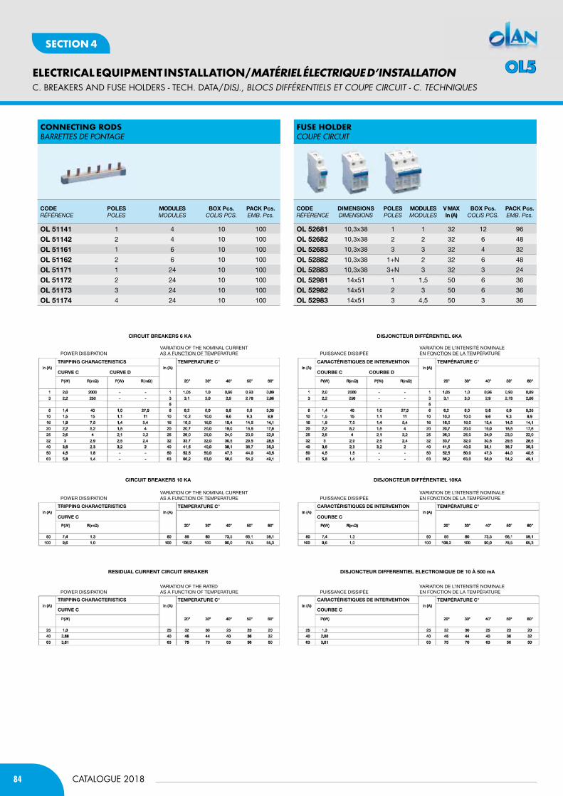
84
ELECTRICAL EQUIPMENT INSTALLATION/MATÉRIEL ÉLECTRIQUE D’INSTALLATION
CATALOGUE 2018
SECTION 4
C. bREAKERS AND fUSE HOLDERS - TECH. DATA/DiSj., BLOcS DifféRENtiELS Et cOUpE ciRcUit - c. tEcHNiQUES
connectinG rodSBARRETTEs DE PONTAGE
fUSe HoLderCOUPE CIRCUIT
CODERÉFÉRENCE
POlESPoLEs
mODUlESModuLEs
bOx Pcs.CoLis PCs.
PACK Pcs.EMB. Pcs.
Ol 51141 1 4 10 100
Ol 51142 2 4 10 100
Ol 51161 1 6 10 100
Ol 51162 2 6 10 100
Ol 51171 1 24 10 100
Ol 51172 2 24 10 100
Ol 51173 3 24 10 100
Ol 51174 4 24 10 100
CODERÉFÉRENCE
DimEnSiOnSdiMENsioNs
POlESPoLEs
mODUlESModuLEs
V mAxin (A)
bOx Pcs.CoLis PCs.
PACK Pcs.EMB. Pcs.
Ol 52681 10,3x38 1 1 32 12 96
Ol 52682 10,3x38 2 2 32 6 48
Ol 52683 10,3x38 3 3 32 4 32
Ol 52882 10,3x38 1+N 2 32 6 48
Ol 52883 10,3x38 3+N 3 32 3 24
Ol 52981 14x51 1 1,5 50 6 36
Ol 52982 14x51 2 3 50 6 36
Ol 52983 14x51 3 4,5 50 3 36
CiRCUit bREAKERS 6 KA
CiRCUit bREAKERS 10 KA
RESiDUAl CURREnt CiRCUit bREAKER
POwer dIssIPAtION
POwer dIssIPAtION
POwer dIssIPAtION
tRiPPinG CHARACtERiStiCS
tRiPPinG CHARACtERiStiCS
tRiPPinG CHARACtERiStiCS
CURVE C
CURVE C
CURVE C
CURVE D
tEmPERAtURE C°
tEmPERAtURE C°
tEmPERAtURE C°
vArIAtION Of the NOmINAL CurreNt As A fuNCtION Of temPerAture
vArIAtION Of the NOmINAL CurreNt As A fuNCtION Of temPerAture
vArIAtION Of the rAted As A fuNCtION Of temPerAture
DiSJOnCtEUR DiFFéREntiEl 6KA
DiSJOnCtEUR DiFFéREntiEl 10KA
DiSJOnCtEUR DiFFEREntiEl ElECtROniqUE DE 10 à 500 mA
PuIssANCe dIssIPée
PuIssANCe dIssIPée
PuIssANCe dIssIPée
CARACtéRiStiqUES DE intERVEntiOn
CARACtéRiStiqUES DE intERVEntiOn
CARACtéRiStiqUES DE intERVEntiOn
COURbE C
COURbE C
COURbE C
COURbE D
tEmPéRAtURE C°
tEmPéRAtURE C°
tEmPéRAtURE C°
vArIAtION de L’INteNsIté NOmINALe eN fONCtION de LA temPérAture
vArIAtION de L’INteNsIté NOmINALe eN fONCtION de LA temPérAture
vArIAtION de L’INteNsIté NOmINALe eN fONCtION de LA temPérAture
OL5
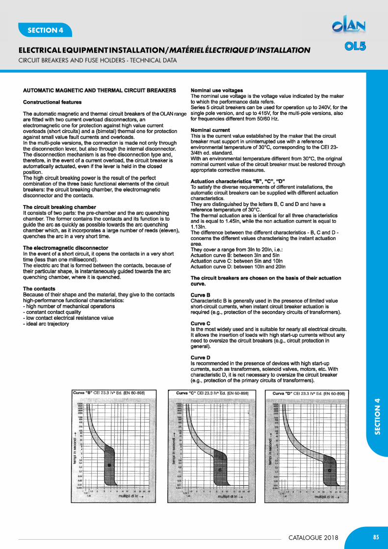
85CATALOGUE 2018
ELECTRICAL EQUIPMENT INSTALLATION/MATÉRIEL ÉLECTRIQUE D’INSTALLATION
SECT
ION
4
SECTION 4
CIRCUIT bREAKERS AND fUSE HOLDERS - TECHNICAL DATA
CURVE CURVE CURVE
OLAN range
OL5
86
ELECTRICAL EQUIPMENT INSTALLATION/MATÉRIEL ÉLECTRIQUE D’INSTALLATION
CATALOGUE 2018
SECTION 4
CIRCUIT bREAKERS AND fUSE HOLDERS - TECHNICAL DATA
OL5
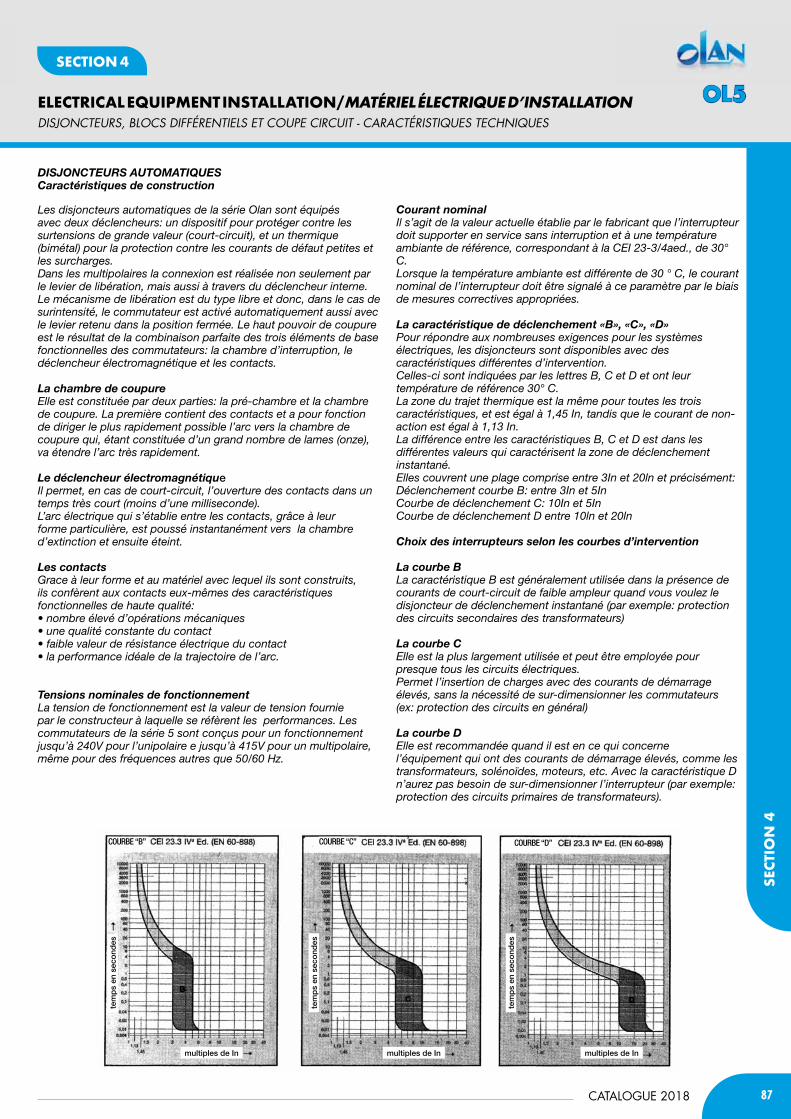
87CATALOGUE 2018
ELECTRICAL EQUIPMENT INSTALLATION/MATÉRIEL ÉLECTRIQUE D’INSTALLATION
SECT
ION
4
SECTION 4
DiSjONctEURS, BLOcS DifféRENtiELS Et cOUpE ciRcUit - caRactéRiStiQUES tEcHNiQUES
COURBE “B” COURBE “C” COURBE “D”
tem
ps
en s
eco
ndes
tem
ps
en s
eco
ndes
tem
ps
en s
eco
ndes
multiples de In multiples de In multiples de In
Les disjoncteurs automatiques de la série Olan sont équipés avec deux déclencheurs: un dispositif pour protéger contre les surtensions de grande valeur (court-circuit), et un thermique (bimétal) pour la protection contre les courants de défaut petites et les surcharges.dans les multipolaires la connexion est réalisée non seulement par le levier de libération, mais aussi à travers du déclencheur interne.Le mécanisme de libération est du type libre et donc, dans le cas de surintensité, le commutateur est activé automatiquement aussi avec le levier retenu dans la position fermée. Le haut pouvoir de coupure est le résultat de la combinaison parfaite des trois éléments de base fonctionnelles des commutateurs: la chambre d’interruption, le déclencheur électromagnétique et les contacts.
La chambre de coupureElle est constituée par deux parties: la pré-chambre et la chambre de coupure. La première contient des contacts et a pour fonction de diriger le plus rapidement possible l’arc vers la chambre de coupure qui, étant constituée d’un grand nombre de lames (onze), va étendre l’arc très rapidement.
Le déclencheur électromagnétiqueIl permet, en cas de court-circuit, l’ouverture des contacts dans un temps très court (moins d’une milliseconde).L’arc électrique qui s’établie entre les contacts, grâce à leur forme particulière, est poussé instantanément vers la chambre d’extinction et ensuite éteint.
Les contactsGrace à leur forme et au matériel avec lequel ils sont construits, ils confèrent aux contacts eux-mêmes des caractéristiques fonctionnelles de haute qualité:• nombre élevé d’opérations mécaniques• une qualité constante du contact• faible valeur de résistance électrique du contact• la performance idéale de la trajectoire de l’arc.
Tensions nominales de fonctionnementLa tension de fonctionnement est la valeur de tension fournie par le constructeur à laquelle se réfèrent les performances. Les commutateurs de la série 5 sont conçus pour un fonctionnement jusqu’à 240V pour l’unipolaire e jusqu’à 415V pour un multipolaire, même pour des fréquences autres que 50/60 hz.
courant nominalIl s’agit de la valeur actuelle établie par le fabricant que l’interrupteur doit supporter en service sans interruption et à une température ambiante de référence, correspondant à la CEI 23-3/4aed., de 30° C.Lorsque la température ambiante est différente de 30 ° C, le courant nominal de l’interrupteur doit être signalé à ce paramètre par le biais de mesures correctives appropriées.
La caractéristique de déclenchement «B», «c», «d»Pour répondre aux nombreuses exigences pour les systèmes électriques, les disjoncteurs sont disponibles avec des caractéristiques différentes d’intervention.Celles-ci sont indiquées par les lettres B, C et d et ont leur température de référence 30° C.La zone du trajet thermique est la même pour toutes les trois caractéristiques, et est égal à 1,45 In, tandis que le courant de non-action est égal à 1,13 In.La différence entre les caractéristiques B, C et d est dans les différentes valeurs qui caractérisent la zone de déclenchement instantané.Elles couvrent une plage comprise entre 3In et 20ln et précisément:Déclenchement courbe B: entre 3In et 5InCourbe de déclenchement C: 10In et 5InCourbe de déclenchement d entre 10ln et 20ln
choix des interrupteurs selon les courbes d’intervention
La courbe BLa caractéristique B est généralement utilisée dans la présence de courants de court-circuit de faible ampleur quand vous voulez le disjoncteur de déclenchement instantané (par exemple: protection des circuits secondaires des transformateurs)
La courbe cElle est la plus largement utilisée et peut être employée pour presque tous les circuits électriques.Permet l’insertion de charges avec des courants de démarrage élevés, sans la nécessité de sur-dimensionner les commutateurs (ex: protection des circuits en général)
La courbe dElle est recommandée quand il est en ce qui concerne l’équipement qui ont des courants de démarrage élevés, comme les transformateurs, solénoïdes, moteurs, etc. Avec la caractéristique D n’aurez pas besoin de sur-dimensionner l’interrupteur (par exemple: protection des circuits primaires de transformateurs).
diSJOncTEUrS aUTOMaTiQUEScaractéristiques de construction
OL5
88
ELECTRICAL EQUIPMENT INSTALLATION/MATÉRIEL ÉLECTRIQUE D’INSTALLATION
CATALOGUE 2018
SECTION 4
DiSjONctEURS, BLOcS DifféRENtiELS Et cOUpE ciRcUit - caRactéRiStiQUES tEcHNiQUES
Pouvoir de court-circuitLe pouvoir de court-circuit est la valeur de la composante alternée du courant présumé, exprimée dans sa valeur effective, que le commutateur est en mesure d’établir, résister au temps d’ouverture et d’arrêter dans des conditions spécifiques.il doit être au moins égal au courant de court-circuit tri-phasique présumé qui peut se produire à l’endroit où il est installé.Exception: il peut être inférieur au courant de court-circuit si en amont si il ya un dispositif qui:a) a le pouvoir d’interrompre correspondant au courant de court-circuit dans le point où le réseau est installé;b) limite l’énergie spécifique passant à une valeur inférieure auquel du disjoncteur en descente des conducteurs.La puissance de court-circuit nominale est ce qui est montré sur le front de l’interrupteur, tel que requis par la CEi 23-3/4aed., Et elle est représentée par une valeur normale entre ceux qui sont définis par la présente norme. Le pouvoir de court-circuit doit être évaluée selon EN60898 signalé en ampères dans un rectangle et non pas le symbole de l’unité de mesure.Le pouvoir de court-circuit augmente généralement avec la diminution du courant nominal de ladite disjoncteur.
Energie passanteLa fonction d’un disjoncteur est de protéger les conducteurs et les appareils électriques en général contre les stress thermiques et dynamiques. En cas de court-circuit l’interrupteur ne doit pas laisser passer un courant plus élevé que celui auquel le câble et l’équipement peut tolérer. Dans le cas où le commutateur est surdimensionné ou en présence de câbles de faible section, il est nécessaire de faire en sorte que le courant de court-circuit à l’extrémité des câbles provoque l’ouverture de l’interrupteur au moyen des déclencheurs magnétiques.
domaines d’utilisationLes commutateurs avec pouvoir de coupure de 6000A sont adaptés pour une utilisation en secteur civile, dans le secteur des services et de la petite industrie.Approbation TUV obtenue à partir de disjoncteurs de la séries 5 pour la caractéristique C 1, 2, 3 & 4, pour le système de tension nominale 120/240V AC et 250/415V c.a. vous permet d’utiliserces commutateurs dans tous les pays de l’UE et d’autres pays où une telle approbation est accordée.
disjoncteurs différentielsLe différentiel ou disjoncteur différentiel est un dispositif de mesure différentielle associée à un tore qui enveloppe les conducteurs actifs d’un circuit et qui permet de détecter toute fuite de courant. Dans des conditions de fonctionnement normal de l’usine, c’est à dire en l’absence de défauts d’isolation, les courants qui parcourent les conducteurs d’alimentation sont parfaitement identiques, et le flux résultant égal à zéro.Si une panne survient (isolation cassé ou un contact accidentel) il y aura un courant de défaut.La différentiel vérifie la différence entre “courant entrant» et «courant sortant” et, si nécessaire, ouvrira les contacts et mettra le système hors de tension.Le différentiel peut:1 - une partie intégrante de l’appareil de coupure (disjoncteur différentiel)2 - être directement associée à l’appareil (disjoncteur + blocage de différentiel)3 - d’être en dehors du circuit (tore relais différentiel)
Porte-fusibles MOdULairES
GénéralitéLes porte-fusibles modulaires de la série 5 sont des appareils adaptés pour loger des fusibles cylindriques ACR et ils font la protection des circuits électriques à travers de la cartouche et font l’isolement du, en utilisant la poignée de la porte.Les exécutions multipolaires sont assemblées dans l’usine pour assurer la sécurité de l’accouplement et, par conséquent, un meilleur actionnement de l’appareil.Les porte-fusibles sont en matériel isolant à auto-extinction selon les normes iEC269 / 2 et VdE0636.
caractéristiquesLa construction modulaire avec module de 18 mm.Les pinces en cuivre plaqués argent et la grande taille permettent une connexion sécurisée du fusible pour une meilleure et stable connexion.Les porte-fusibles sont fournis avec un cliquet qui, à fusible inséré, lui bloque à l’intérieur, en évitant le mouvement, dans n’importe quelle installation lourde.Les bornes de connexion des câbles, de grands dimensions, permettent l’installation de fils jusqu’à 35 mm².
OL5
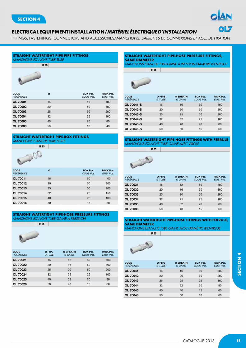
89CATALOGUE 2018
ELECTRICAL EQUIPMENT INSTALLATION/MATÉRIEL ÉLECTRIQUE D’INSTALLATION
SECT
ION
4
SECTION 4
fITTINGS, fASTENINGS, CONNECTORS AND ACCESSORIES/MaNcHONS, BaRREttES DE cONNExiONS Et acc. DE fixatiON
StraiGHt WatertiGHt PiPe-PiPe fittinGSMANCHONs ETANCHE TUBE-TUBE
IP 65
StraiGHt WatertiGHt PiPe-HoSe PreSSUre fittinGSMANCHONs ETANCHE TUBE-GAINE à PREssION
IP 65
StraiGHt WatertiGHt PiPe-HoSe PreSSUre fittinGS, SaMe diaMeterMANCHONs ETANCHE TUBE-GAINE à PREssION DIAMèTRE IDENTIQUE
IP 65
StraiGHt WatertiGHt PiPe-HoSe fittinGS WitH ferrULeMANCHONs ETANCHE TUBE-GAINE AVEC VIROLE
IP 65
StraiGHt WatertiGHt PiPe-HoSe fittinGS WitH ferrULe, SaMe diaMeterMANCHONs ETANCHE TUBE-GAINE AVEC DIAMèTRE IDENTIQUE
IP 65
CODERÉFÉRENCE
Ø bOx Pcs.CoLis Pcs.
PACK Pcs.EMB. Pcs.
Ol 70001 16 50 400
Ol 70002 20 50 300
Ol 70003 25 50 200
Ol 70004 32 25 100
Ol 70005 40 20 80
Ol 70006 50 10 40
CODERÉFÉRENCE
Ø bOx Pcs.CoLis Pcs.
PACK Pcs.EMB. Pcs.
Ol 70011 16 50 400
Ol 70012 20 50 300
Ol 70013 25 50 200
Ol 70014 32 25 150
Ol 70015 40 25 100
Ol 70016 50 15 60
CODERÉFÉRENCE
Ø PiPEØ tuBE
Ø SHEAtH Ø GAiNE
bOx Pcs.CoLis Pcs.
PACK Pcs.EMB. Pcs.
Ol 70021 16 12 50 400
Ol 70022 20 16 50 300
Ol 70023 25 20 50 200
Ol 70024 32 25 25 100
Ol 70025 40 32 20 80
Ol 70026 50 40 15 60
CODERÉFÉRENCE
Ø PiPEØ tuBE
Ø SHEAtH Ø GAiNE
bOx Pcs.CoLis Pcs.
PACK Pcs.EMB. Pcs.
Ol 70041-S 16 16 50 400
Ol 70042-S 20 20 50 300
Ol 70043-S 25 25 50 200
Ol 70044-S 32 32 25 100
Ol 70045-S 40 40 20 80
Ol 70046-S 50 50 15 60
CODERÉFÉRENCE
Ø PiPEØ tuBE
Ø SHEAtH Ø GAiNE
bOx Pcs.CoLis Pcs.
PACK Pcs.EMB. Pcs.
Ol 70031 16 12 50 400
Ol 70032 20 16 50 300
Ol 70033 25 20 50 200
Ol 70034 32 25 25 100
Ol 70035 40 32 20 80
Ol 70036 50 40 15 60
CODERÉFÉRENCE
Ø PiPEØ tuBE
Ø SHEAtH Ø GAiNE
bOx Pcs.CoLis Pcs.
PACK Pcs.EMB. Pcs.
Ol 70041 16 16 50 300
Ol 70042 20 20 50 200
Ol 70043 25 25 25 100
Ol 70044 32 32 20 80
Ol 70045 40 40 15 60
Ol 70046 50 50 10 60
StraiGHt WatertiGHt PiPe-BoX fittinGSMANCHONs ETANCHE TUBE-BOîTE
IP 65
OL7
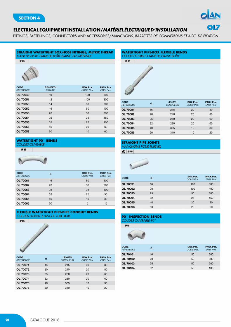
90
ELECTRICAL EQUIPMENT INSTALLATION/MATÉRIEL ÉLECTRIQUE D’INSTALLATION
CATALOGUE 2018
SECTION 4
fITTINGS, fASTENINGS, CONNECTORS AND ACCESSORIES/MaNcHONS, BaRREttES DE cONNExiONS Et acc. DE fixatiON
StraiGHt WatertiGHt BoX-HoSe fittinGS, Metric tHreadMANCHONs IRL ETANCHE BOîTE-GAINE, PAs MéTRIQUE
IP 65
fLeXiBLe WatertiGHt PiPe-PiPe condUit BendSCOUDEs FLEXIBLE ETANCHE TUBE-TUBE
IP 65
WatertiGHt PiPe-BoX fLeXiBLe BendSCOUDEs FLEXIBLE ETANCHE GAINE-BOîTE
IP 65
90° inSPection BendSCOUDEs OUVRABLE 90°
IP40
CODERÉFÉRENCE
Ø SHEAtH Ø GAiNE
bOx Pcs.CoLis Pcs.
PACK Pcs.EMB. Pcs.
Ol 70049 10 100 800
Ol 70051 12 100 800
Ol 70050 14 50 800
Ol 70052 16 50 400
Ol 70053 20 50 300
Ol 70054 25 25 150
Ol 70055 32 25 100
Ol 70056 40 20 60
Ol 70057 50 10 60
CODERÉFÉRENCE
ØbOx Pcs.
CoLis Pcs.PACK Pcs.EMB. Pcs.
Ol 70061 16 50 300
Ol 70062 20 50 200
Ol 70063 25 25 100
Ol 70064 32 25 50
Ol 70065 40 10 30
Ol 70066 50 5 15
CODERÉFÉRENCE
ØlEnGtH
LoNGuEuRbOx Pcs.
CoLis Pcs.PACK Pcs.EMB. Pcs.
Ol 70071 16 215 20 80
Ol 70072 20 240 20 80
Ol 70073 25 260 20 60
Ol 70074 32 280 20 60
Ol 70075 40 305 10 30
Ol 70076 50 310 10 20
CODERÉFÉRENCE
ØlEnGtH
LoNGuEuRbOx Pcs.
CoLis Pcs.PACK Pcs.EMB. Pcs.
Ol 70081 16 215 20 80
Ol 70082 20 240 20 80
Ol 70083 25 260 20 60
Ol 70084 32 280 20 60
Ol 70085 40 305 10 30
Ol 70086 50 310 10 20
CODE ØbOx Pcs.
CoLis Pcs.PACK Pcs.EMB. Pcs.
Ol 70091 16 100 600
Ol 70092 20 100 400
Ol 70093 25 50 300
Ol 70094 32 25 150
Ol 70095 40 20 80
Ol 70096 50 20 60
CODERÉFÉRENCE
ØbOx Pcs.
CoLis Pcs.PACK Pcs.EMB. Pcs.
Ol 70101 16 50 600
Ol 70102 20 50 300
Ol 70103 25 50 200
Ol 70104 32 50 100
WatertiGHt 90° BendSCOUDEs OUVRABLE
IP 65
StraiGHt PiPe jointSMANCHONs POUR TUBE IRL
IP 40
OL7
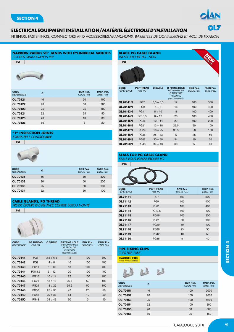
91CATALOGUE 2018
ELECTRICAL EQUIPMENT INSTALLATION/MATÉRIEL ÉLECTRIQUE D’INSTALLATION
SECT
ION
4
SECTION 4
“t” inSPection jointSJOINTs EN T CONTRÔLABLE
IP40
caBLe GLandS, PG tHreadPREssE éTOUPE PAs PG AVEC CONTRE éCROU MONTé
IP40
CODERÉFÉRENCE
PG tHREADPAs PG
Ø CAblE Ø FixinG HOlE(reCOmmeNded)
Ø tRou dE FixAtioN
(RECoMMANdÉ)
bOx Pcs.CoLis Pcs.
PACK Pcs.EMB. Pcs.
Ol 70141 PG7 3,5 ÷ 6,5 12 100 500
Ol 70142 PG9 4 ÷ 8 16 100 400
Ol 70143 PG11 5 ÷ 10 18 100 400
Ol 70144 PG13,5 6 ÷ 12 20 100 400
Ol 70145 PG16 10 ÷ 14 22 100 200
Ol 70146 PG21 13 ÷ 18 26,5 50 100
Ol 70147 PG29 18 ÷ 25 35,5 50 100
Ol 70148 PG36 25 ÷ 33 47 25 50
Ol 70149 PG42 30 ÷ 38 54 10 50
Ol 70150 PG48 34 ÷ 43 60 5 40
CODERÉFÉRENCE
ØbOx Pcs.
CoLis Pcs.PACK Pcs.EMB. Pcs.
Ol 70131 16 50 300
Ol 70132 20 50 200
Ol 70133 25 50 100
Ol 70134 32 50 100
narroW radiUS 90° BendS WitH cyLindricaL MoUtHSCOUDEs GRAND RAyON 90°
IP40
CODERÉFÉRENCE
ØbOx Pcs.
CoLis Pcs.PACK Pcs.EMB. Pcs.
Ol 70121 16 50 400
Ol 70122 20 50 200
Ol 70123 25 25 100
Ol 70124 32 25 50
Ol 70125 40 10 30
Ol 70126 50 5 20
fITTINGS, fASTENINGS, CONNECTORS AND ACCESSORIES/MaNcHONS, BaRREttES DE cONNExiONS Et acc. DE fixatiON
CODERÉFÉRENCE
ØbOx Pcs.
CoLis Pcs.PACK Pcs.EMB. Pcs.
Ol 70151 16 100 2000
Ol 70152 20 100 2000
Ol 70153 25 100 1200
Ol 70154 32 100 800
Ol 70155 40 50 300
Ol 70156 50 25 150
BLacK PG caBLe GLandPREssE-éTOUPE PG - NOIR
IP40
PiPe fiXinG cLiPSCLIPs FIXE-TUBEHALOGEN FREEsAns HALogenes
CODERÉFÉRENCE
PG tHREADPAs PG
bOx Pcs.CoLis Pcs.
PACK Pcs.EMB. Pcs.
Ol71141 PG7 100 500
Ol71142 PG9 100 400
Ol71143 PG11 100 400
Ol71144 PG13,5 100 400
Ol71145 PG16 100 200
Ol71146 PG21 50 100
Ol71147 PG29 50 100
Ol71148 PG36 25 50
Ol71149 PG42 10 50
Ol71150 PG48 5 40
SeaLS for PG caBLe GLandsEALs POUR PREssE-éTOUPE PG
IP 65
CODERÉFÉRENCE
PG tHREADPAs PG
Ø CAblE Ø FixinG HOlE(reCOmmeNded)
Ø tRou dE FixAtioN
(RECoMMANdÉ)
bOx Pcs.CoLis Pcs.
PACK Pcs.EMB. Pcs.
Ol70141n PG7 3,5 ÷ 6,5 12 100 500
Ol70142n PG9 4 ÷ 8 16 100 400
Ol70143n PG11 5 ÷ 10 18 100 400
Ol70144n PG13,5 6 ÷ 12 20 100 400
Ol70145n PG16 10 ÷ 14 22 100 200
Ol70146n PG21 13 ÷ 18 26,5 50 100
Ol70147n PG29 18 ÷ 25 35,5 50 100
Ol70148n PG36 25 ÷ 33 47 25 50
Ol70149n PG42 30 ÷ 38 54 10 50
Ol70150n PG48 34 ÷ 43 60 5 40
OL7
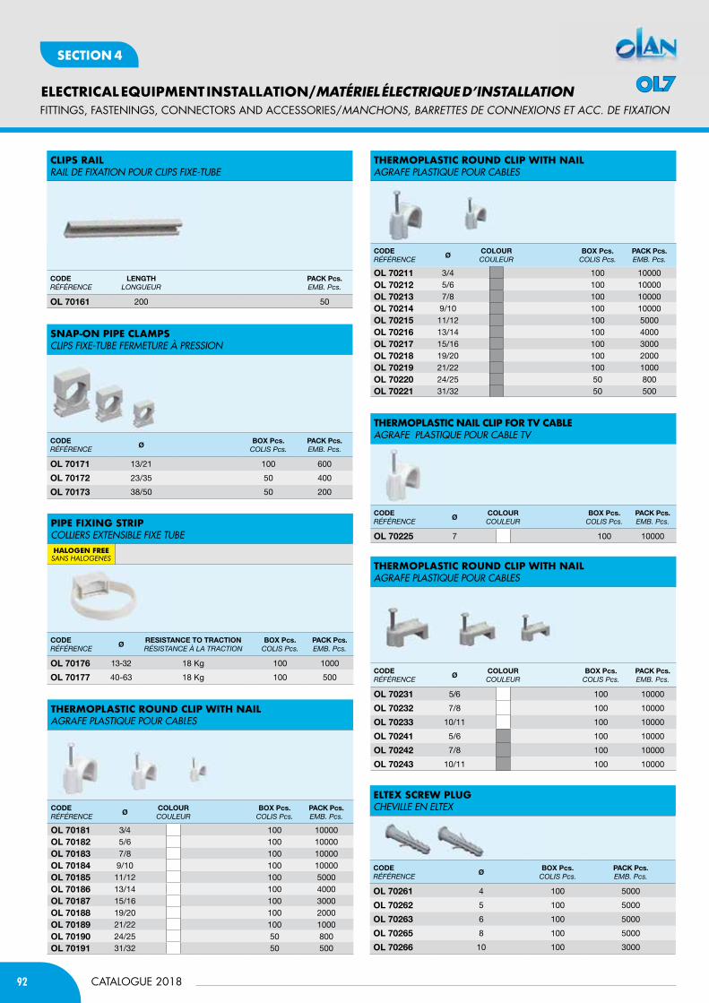
92
ELECTRICAL EQUIPMENT INSTALLATION/MATÉRIEL ÉLECTRIQUE D’INSTALLATION
CATALOGUE 2018
SECTION 4
fITTINGS, fASTENINGS, CONNECTORS AND ACCESSORIES/MaNcHONS, BaRREttES DE cONNExiONS Et acc. DE fixatiON
tHerMoPLaStic roUnd cLiP WitH naiLAGRAFE PLAsTIQUE POUR CABLEs
tHerMoPLaStic roUnd cLiP WitH naiLAGRAFE PLAsTIQUE POUR CABLEs
tHerMoPLaStic naiL cLiP for tv caBLeAGRAFE PLAsTIQUE POUR CABLE TV
tHerMoPLaStic roUnd cLiP WitH naiLAGRAFE PLAsTIQUE POUR CABLEs
CODERÉFÉRENCE
ØCOlOURCouLEuR
bOx Pcs.CoLis Pcs.
PACK Pcs.EMB. Pcs.
Ol 70211 3/4 100 10000Ol 70212 5/6 100 10000Ol 70213 7/8 100 10000Ol 70214 9/10 100 10000Ol 70215 11/12 100 5000Ol 70216 13/14 100 4000Ol 70217 15/16 100 3000Ol 70218 19/20 100 2000Ol 70219 21/22 100 1000Ol 70220 24/25 50 800Ol 70221 31/32 50 500
CODERÉFÉRENCE
ØCOlOURCouLEuR
bOx Pcs.CoLis Pcs.
PACK Pcs.EMB. Pcs.
Ol 70181 3/4 100 10000Ol 70182 5/6 100 10000Ol 70183 7/8 100 10000Ol 70184 9/10 100 10000Ol 70185 11/12 100 5000Ol 70186 13/14 100 4000Ol 70187 15/16 100 3000Ol 70188 19/20 100 2000Ol 70189 21/22 100 1000Ol 70190 24/25 50 800Ol 70191 31/32 50 500
CODERÉFÉRENCE
ØCOlOURCouLEuR
bOx Pcs.CoLis Pcs.
PACK Pcs.EMB. Pcs.
Ol 70225 7 100 10000
CODERÉFÉRENCE
ØCOlOURCouLEuR
bOx Pcs.CoLis Pcs.
PACK Pcs.EMB. Pcs.
Ol 70231 5/6 100 10000
Ol 70232 7/8 100 10000
Ol 70233 10/11 100 10000
Ol 70241 5/6 100 10000
Ol 70242 7/8 100 10000
Ol 70243 10/11 100 10000
SnaP-on PiPe cLaMPSCLIPs FIXE-TUBE FERMETURE à PREssION
CODERÉFÉRENCE
ØRESiStAnCE tO tRACtiOnRÉsistANCE À LA tRACtioN
bOx Pcs.CoLis Pcs.
PACK Pcs.EMB. Pcs.
Ol 70176 13-32 18 Kg 100 1000
Ol 70177 40-63 18 Kg 100 500
cLiPS raiLRAIL DE FIXATION POUR CLIPs FIXE-TUBE
CODERÉFÉRENCE
lEnGtHLoNGuEuR
PACK Pcs.EMB. Pcs.
Ol 70161 200 50
CODERÉFÉRENCE
ØbOx Pcs.
CoLis Pcs.PACK Pcs.EMB. Pcs.
Ol 70171 13/21 100 600
Ol 70172 23/35 50 400
Ol 70173 38/50 50 200
PiPe fiXinG StriPCOLLIERs EXTENsIBLE FIXE TUBEHALOGEN FREEsAns HALogenes
eLteX ScreW PLUGCHEVILLE EN ELTEX
CODERÉFÉRENCE
ØbOx Pcs.
CoLis Pcs.PACK Pcs.EMB. Pcs.
Ol 70261 4 100 5000
Ol 70262 5 100 5000
Ol 70263 6 100 5000
Ol 70265 8 100 5000
Ol 70266 10 100 3000
OL7
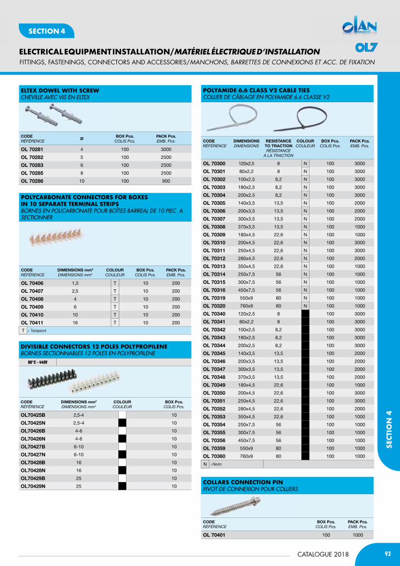
93CATALOGUE 2018
ELECTRICAL EQUIPMENT INSTALLATION/MATÉRIEL ÉLECTRIQUE D’INSTALLATION
SECT
ION
4
SECTION 4
CODERÉFÉRENCE
DimEnSiOnS mm2
diMENsioNs mm2
COlOURCouLEuR
bOx Pcs.CoLis Pcs.
Ol70425b 2,5-4 10
Ol70425n 2,5-4 10
Ol70426b 4-6 10
Ol70426n 4-6 10
Ol70427b 6-10 10
Ol70427n 6-10 10
Ol70428b 16 10
Ol70428n 16 10
Ol70429b 25 10
Ol70429n 25 10
diviSiBLe connectorS 12 PoLeS PoLyProPiLeneBORNEs sECTIONNABLEs 12 POLEs EN POLyPROPILENE
80°C - 440V
CODERÉFÉRENCE
DimEnSiOnSdiMENsioNs
RESiStAnCE tO tRACtiOnRÉsistANCE
À LA tRACtioN
COlOURCouLEuR
bOx Pcs.CoLis Pcs.
PACK Pcs.EMB. Pcs.
Ol 70300 120x2,5 8 N 100 3000
Ol 70301 80x2,2 8 N 100 3000
Ol 70302 100x2,5 8,2 N 100 3000
Ol 70303 180x2,5 8,2 N 100 3000
Ol 70304 200x2,5 8,2 N 100 3000
Ol 70305 140x3,5 13,5 N 100 2000
Ol 70306 200x3,5 13,5 N 100 2000
Ol 70307 300x3,5 13,5 N 100 2000
Ol 70308 370x3,5 13,5 N 100 1000
Ol 70309 180x4,5 22,6 N 100 1000
Ol 70310 200x4,5 22,6 N 100 3000
Ol 70311 250x4,5 22,6 N 100 3000
Ol 70312 280x4,5 22,6 N 100 2000
Ol 70313 350x4,5 22,6 N 100 1000
Ol 70314 250x7,5 56 N 100 1000
Ol 70315 300x7,5 56 N 100 1000
Ol 70316 450x7,5 56 N 100 1000
Ol 70319 550x9 80 N 100 1000
Ol 70320 760x9 80 N 100 1000
Ol 70340 120x2,5 8 100 3000
Ol 70341 80x2,2 8 100 3000
Ol 70342 100x2,5 8,2 100 3000
Ol 70343 180x2,5 8,2 100 3000
Ol 70344 200x2,5 8,2 100 3000
Ol 70345 140x3,5 13,5 100 2000
Ol 70346 200x3,5 13,5 100 2000
Ol 70347 300x3,5 13,5 100 2000
Ol 70348 370x3,5 13,5 100 2000
Ol 70349 180x4,5 22,6 100 1000
Ol 70350 200x4,5 22,6 100 3000
Ol 70351 250x4,5 22,6 100 3000
Ol 70352 280x4,5 22,6 100 2000
Ol 70353 350x4,5 22,6 100 1000
Ol 70354 250x7,5 56 100 1000
Ol 70355 300x7,5 56 100 1000
Ol 70356 450x7,5 56 100 1000
Ol 70359 550x9 80 100 1000
Ol 70360 760x9 80 100 1000
= NeutreN
coLLarS connection PinPIVOT DE CONNEXION POUR COLLIERs
CODERÉFÉRENCE
bOx Pcs.CoLis Pcs.
PACK Pcs.EMB. Pcs.
Ol 70401 100 1000
PoLyaMide 6.6 cLaSS v2 caBLe tieSCOLLIER DE CÂBLAGE EN POLyAMIDE 6.6 CLAssE V2
CODERÉFÉRENCE
DimEnSiOnS mm2
diMENsioNs mm2
COlOURCouLEuR
bOx Pcs.CoLis Pcs.
PACK Pcs.EMB. Pcs.
Ol 70406 1,5 T 10 200
Ol 70407 2,5 T 10 200
Ol 70408 4 T 10 200
Ol 70409 6 T 10 200
Ol 70410 10 T 10 200
Ol 70411 16 T 10 200
= Transparent
PoLycarBonate connectorS for BoXeS in 10 SeParate terMinaL StriPSBORNEs EN POLICARBONATE POUR BOîTEs BARREAL DE 10 PIEC. A sECTIONNER
T
eLteX doWeL WitH ScreWCHEVILLE AVEC VIs EN ELTEX
CODERÉFÉRENCE
ØbOx Pcs.
CoLis Pcs.PACK Pcs.EMB. Pcs.
Ol 70281 4 100 3000
Ol 70282 5 100 2500
Ol 70283 6 100 2500
Ol 70285 8 100 2500
Ol 70286 10 100 900
fITTINGS, fASTENINGS, CONNECTORS AND ACCESSORIES/MaNcHONS, BaRREttES DE cONNExiONS Et acc. DE fixatiON
OL7
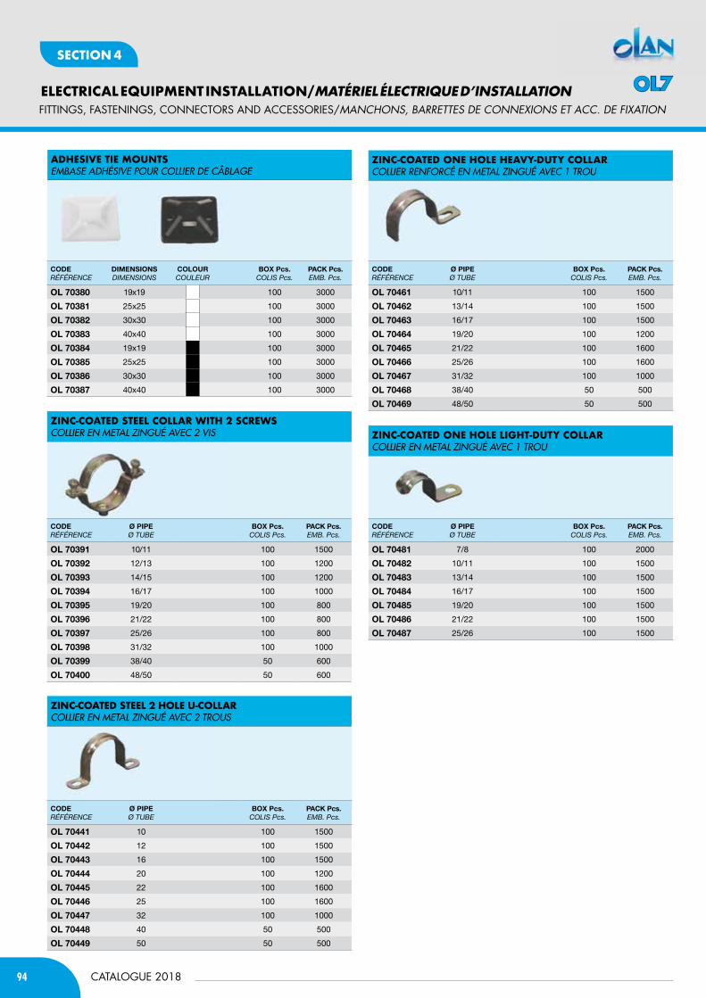
94
ELECTRICAL EQUIPMENT INSTALLATION/MATÉRIEL ÉLECTRIQUE D’INSTALLATION
CATALOGUE 2018
SECTION 4
Zinc-coated one HoLe Heavy-dUty coLLarCOLLIER RENFORCé EN METAL ZINGUé AVEC 1 TROU
Zinc-coated one HoLe LiGHt-dUty coLLarCOLLIER EN METAL ZINGUé AVEC 1 TROU
CODERÉFÉRENCE
Ø PiPEØ tuBE
bOx Pcs.CoLis Pcs.
PACK Pcs.EMB. Pcs.
Ol 70461 10/11 100 1500
Ol 70462 13/14 100 1500
Ol 70463 16/17 100 1500
Ol 70464 19/20 100 1200
Ol 70465 21/22 100 1600
Ol 70466 25/26 100 1600
Ol 70467 31/32 100 1000
Ol 70468 38/40 50 500
Ol 70469 48/50 50 500
CODERÉFÉRENCE
Ø PiPEØ tuBE
bOx Pcs.CoLis Pcs.
PACK Pcs.EMB. Pcs.
Ol 70481 7/8 100 2000
Ol 70482 10/11 100 1500
Ol 70483 13/14 100 1500
Ol 70484 16/17 100 1500
Ol 70485 19/20 100 1500
Ol 70486 21/22 100 1500
Ol 70487 25/26 100 1500
adHeSive tie MoUntSEMBAsE ADHésIVE POUR COLLIER DE CÂBLAGE
CODERÉFÉRENCE
DimEnSiOnSdiMENsioNs
COlOURCouLEuR
bOx Pcs.CoLis Pcs.
PACK Pcs.EMB. Pcs.
Ol 70380 19x19 100 3000
Ol 70381 25x25 100 3000
Ol 70382 30x30 100 3000
Ol 70383 40x40 100 3000
Ol 70384 19x19 100 3000
Ol 70385 25x25 100 3000
Ol 70386 30x30 100 3000
Ol 70387 40x40 100 3000
Zinc-coated SteeL coLLar WitH 2 ScreWSCOLLIER EN METAL ZINGUé AVEC 2 VIs
Zinc-coated SteeL 2 HoLe U-coLLar COLLIER EN METAL ZINGUé AVEC 2 TROUs
CODERÉFÉRENCE
Ø PiPEØ tuBE
bOx Pcs.CoLis Pcs.
PACK Pcs.EMB. Pcs.
Ol 70391 10/11 100 1500
Ol 70392 12/13 100 1200
Ol 70393 14/15 100 1200
Ol 70394 16/17 100 1000
Ol 70395 19/20 100 800
Ol 70396 21/22 100 800
Ol 70397 25/26 100 800
Ol 70398 31/32 100 1000
Ol 70399 38/40 50 600
Ol 70400 48/50 50 600
CODERÉFÉRENCE
Ø PiPEØ tuBE
bOx Pcs.CoLis Pcs.
PACK Pcs.EMB. Pcs.
Ol 70441 10 100 1500
Ol 70442 12 100 1500
Ol 70443 16 100 1500
Ol 70444 20 100 1200
Ol 70445 22 100 1600
Ol 70446 25 100 1600
Ol 70447 32 100 1000
Ol 70448 40 50 500
Ol 70449 50 50 500
fITTINGS, fASTENINGS, CONNECTORS AND ACCESSORIES/MaNcHONS, BaRREttES DE cONNExiONS Et acc. DE fixatiON
OL7
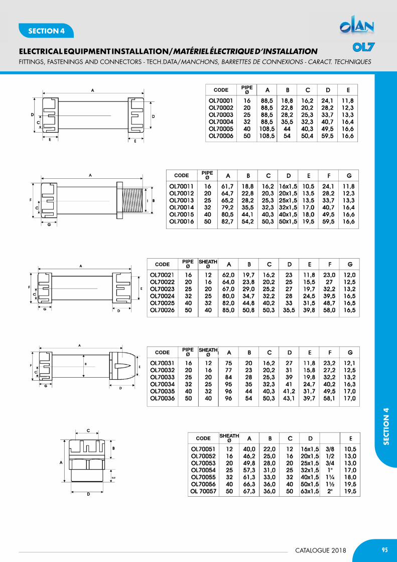
95CATALOGUE 2018
ELECTRICAL EQUIPMENT INSTALLATION/MATÉRIEL ÉLECTRIQUE D’INSTALLATION
SECT
ION
4
SECTION 4
fITTINGS, fASTENINGS AND CONNECTORS - TECH.DATA/MaNcHONS, BaRREttES DE cONNExiONS - caRact. tEcHNiQUES
CODE PiPEØ
PiPEØ
PiPEØ
SHEAtH Ø
SHEAtH Ø
SHEAtHØ
PiPEØ
CODE
CODE
CODE
CODE
OL7
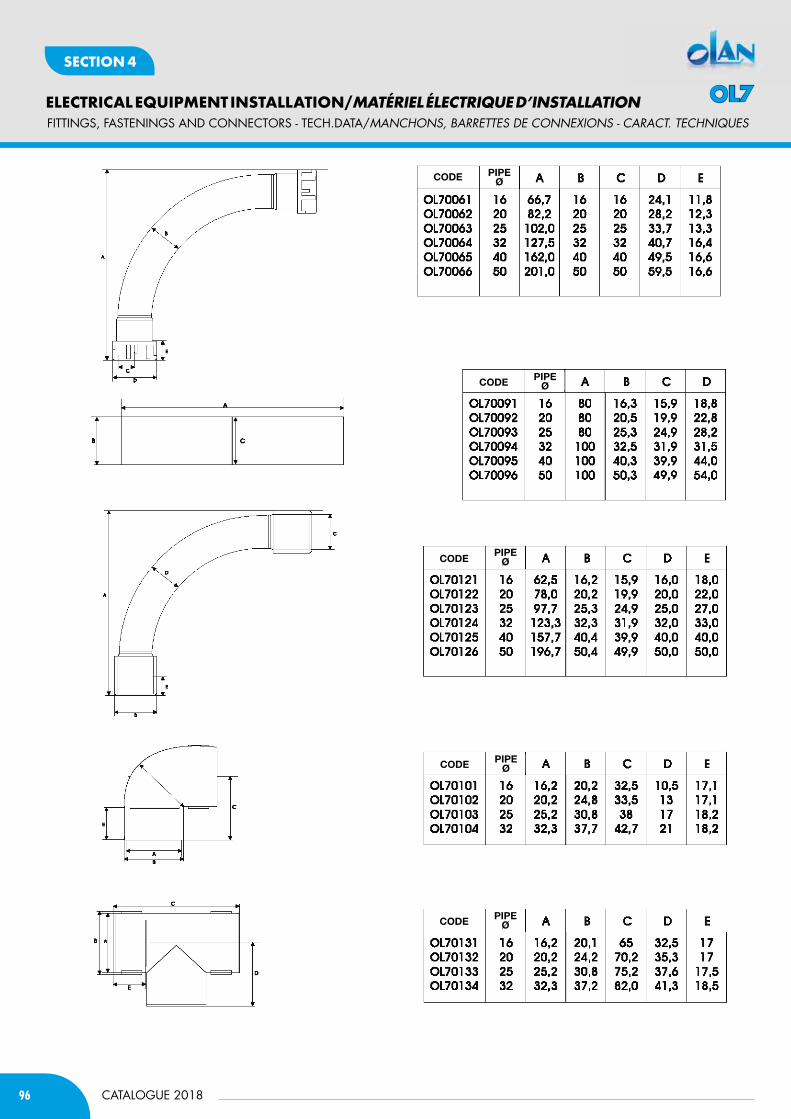
96
ELECTRICAL EQUIPMENT INSTALLATION/MATÉRIEL ÉLECTRIQUE D’INSTALLATION
CATALOGUE 2018
SECTION 4
fITTINGS, fASTENINGS AND CONNECTORS - TECH.DATA/MaNcHONS, BaRREttES DE cONNExiONS - caRact. tEcHNiQUES
CODE
CODE
CODE
CODE
CODE
PiPEØ
PiPEØ
PiPEØ
PiPEØ
PiPEØ
OL7

97CATALOGUE 2018
ELECTRICAL EQUIPMENT INSTALLATION/MATÉRIEL ÉLECTRIQUE D’INSTALLATION
SECT
ION
4
SECTION 4
fISHTApES AND HOSES/cORDONS ExtENSiBLES, tiRE fiLS Et OUtiLS
CODERÉFÉRENCE
lEnGtH (m)LoNGuEuR (m)
ØPACK Pcs.EMB. Pcs.
Ol 90051 5 3 70
Ol 90052 10 3 40
Ol 90053 15 3 30
Ol 90054 20 3 20
Ol 90061 5 4 50
Ol 90062 10 4 25
Ol 90063 15 4 20
Ol 90064 20 4 15
Ol 90065 25 4 12
Ol 90066 30 4 10
CODERÉFÉRENCE
lEnGtH (m)LoNGuEuR (m)
ØPACK Pcs.EMB. Pcs.
Ol 90071 5 4 50
Ol 90072 10 4 25
Ol 90073 15 4 20
Ol 90074 20 4 15
Ol 90075 25 4 12
Ol 90076 30 4 10
CODERÉFÉRENCE
lEnGtH (m)LoNGuEuR (m)
ØPACK Pcs.EMB. Pcs.
Ol 90120 10 4 25
Ol 90121 15 4 20
Ol 90122 20 4 15
Ol 90123 25 4 12
nyLon fiSH taPeS WitH fiXed rinGS and terMinaLSAIGUILLE TIRE FILs EMBOUT EN LAITON
nyLon fiSH taPeS WitH intercHanGeaBLe eyeLetS and terMinaLSTIRE FILs EN NyLON AVEC TêTEs INTERCHANGEABLEs LAITON
HiGH reSiStance PoLyeSter fiSH taPeS WitH intercHanGeaBLe eyeLetS and terMinaLSTIRE FILs HAUTE RésIsTANCE EN POLyEsTER AVEC TêTEs INTERCHANGEABLEs LAITON
CODERÉFÉRENCE
innER ØCOlOURCouLEuR
m PER ROllm PAR RouLEAu
Ol G0010 10 30
Ol G0012 12 30
Ol G0014 14 30
Ol G0016 16 30
Ol G0020 20 30
Ol G0022 22 30
Ol G0025 25 30
Ol G0028 28 30
Ol G0032 32 30
Ol G0035 35 30
Ol G0040 40 30
Ol G0050 50 30
CODERÉFÉRENCE
DESCRiPtiOndEsCRiPtioN
bOx Pcs.CoLis Pcs.
Ol 90080 Connector/Raccord 10
Ol 90081 Unscrewable bullnose leader/Boucle amovible 10
Ol 90082 Bullnose/Embout avec fente 10
acceSSorieS for fiSH taPeS tHread M4ACCEssOIREs POUR TIRE FILs PAs M4
fiSH taPeS diSPLay Stand PRésENTOIR POUR TIRE-FILs
CODERÉFÉRENCE
PACK Pcs.EMB. Pcs.
Ol90999 1
SPiraL HoSeSGAINEs FLEXIBLEGWT 850° IK 07
CODERÉFÉRENCE
ØCOlOURCouLEuR
m PER ROllm PAR RouLEAu
Olt11116 16 100Olt11120 20 100Olt11125 25 50Olt11132 32 25Olt11140 40 25Olt11150 50 25
Olt10161 16 100Olt10201 20 100Olt10251 25 50Olt10321 32 25Olt10401 40 25Olt10501 50 25
• OLT11216 16 100• OLT11220 20 100• OLT11225 25 50• OLT11232 32 25• OLT11240 40 25• OLT11250 50 25
• with wire guide/Gaine prefilée ICTA
corrUGated HoSeSGAINEs ELAsTIQUE
EN 61386-1 EN 61386-22
OL9

98 CATALOGUE 2018
1 - Prices and conditions only become binding at the time of acceptance of the order, by us, with written confirmation. Your purchase order is an implicit acceptance of our General Conditions of Sale. 2 - The conditions and other commitments entered into the quotation by us are only valid if an order is placed for everything which is included in that quotation. 3 - Estimates, outline designs, etc. attached to the quotation are our exclusive property and may not therefore be communicated to third parties without our written authorisation. 4 - Any modifications to the quotation and to these general supply conditions must be in writing and are limited to what is clearly agreed.
WEIGHTS - DIMENSIONS - TECHNICAL DATA 5 - Estimates, projects, drawings, photographs, colors and technical specifications listed in the catalogues, price lists and offers, are meant to be indicative and not binding for the company, which reserves the right to modify them at any time for improving product performances . For more information, please call our. technical department.
PRICES 6 - Prices and discounts on list prices and quotations are subject to variation according to market requirements or in line with variations in the cost of raw materials or labour, without any prior notice to our Customers. Prices are ExW-Incoterms 2010; transport costs, customs, customs duties and any other types of expense are always payable by the Customer, unless otherwise agreed in writing. PACKING AND TRANSPORT 7 - Packaging, which is invoiced at cost, is non-returnable. Our Company standard condition of delivery is ExW and therefore cannot be held responsible for missing or irregular deliveries by carriers, being explicitly understood that, even if the Company helps organize the shipment to the Customer’s premises, the goods travel at the entire risk of the Purchaser. Any return of goods must first be authorised by our Company and goods must be returned free of any cost to our Factory warehouses.
DELIVERY TIMES 8 - Agreed delivery times are indicative and not legally binding and are subject to the clause “unless sold” for goods indicated as ready; they are valid only in normal working and supply conditions. Our Company shall in no circumstances or for any reason be liable to pay compensation of any kind of direct or indirect damage due to late deliveries.
PAYMENT - RETENTION OF PROPERTY TITLE 9 - Payment terms and conditions must be agreed in writing or, failing this, shall be understood to be net cash on delivery of the goods. The goods remain the property of Olan Ltd. and will not be transferred to the client until the same has not made full payment of the price stated in the invoice, meaning the sale under the above condition. Therefore, in case of non-payment, Olan Ltd will be entitled to claim the delivered goods even in case of bankruptcy of the buyer. In the event of late payment, the Customer undertakes to pay interest on delayed payment equivalent to the average market rate applied by Financial Institutions, plus 4%. If the purchaser fails to comply, even partially, with any of the conditions agreed for collection of the goods or for settlement and payment of individual invoices, our Company has the right to immediately suspend further deliveries and consider itself free of any contractual obligation, while retaining all its rights relating to failure to comply with the contract. Unless expressly agreed otherwise, payments must always be made directly to our Company.
CLAIMS 10 - Any claims relating to the supply of goods must reach us within 12 days of receipt of such goods, after which time they will no longer be accepted. Every claim must be based on concrete facts in order to be taken into consideration. We shall be entitled, at our discretion, to take back or replace goods which the Customer demonstrates to be faulty, but will not accept any costs for repairs or modifications which have been made without our authorisation. It remains understood that any claims on any single consignment of goods will have no effect on the balance of the order or the obligation, or on payment for other goods already received without complaint.
WARRANTY 11 - The warranty we offer for products made by us is 12 months from the date of the corresponding invoice and, during this period, we undertake to repair or replace free of charge in our workshops any parts or equipment which are unusable due to defective materials or workmanship. In all cases, we reserve the right to decide, at our entire discretion, whether repair or replacement is most appropriate. We however exclude the possibility of sending our personnel to make on-site inspections to installations where our equipment is installed, except in cases where, at our entire discretion, we believe it is necessary to check the operating conditions to which our equipment has been subjected. 12 - Our warranty is naturally valid provided that the Customer has used and treated our equipment with due care, that the equipment has not been misused or modified and that all the technical requirements contained in our price lists and instruction sheets have been complied with. The warranty does not cover parts which, due to the nature of the material with which they are made or to their specific use, are subject to premature wear; damage due to normal wear and tear is also excluded. 13 - The Customer must send written notification of failures and defects, giving an exact description of their nature and we shall arrange, within the necessary time required, repairs and replacement under the above terms and conditions. Material for repair or replacement must be delivered to us, carriage paid. 14 - With the repair or replacement of the equipment or any of its parts which were defective, our Company shall be relieved of all and any responsibility of any kind, while the Customer shall consider him/herself entirely satisfied by this fact and shall renounce any request for damages and costs. In certain cases, we may allow the Customer to arrange any necessary repairs or replacements, it being understood that our only obligation will be to refund any out-of-pocket expenses accepted as essential to put our equipment in working order. 15 - In the event of disputes of a technical nature, the parties shall submit to the opinion of an expert to be appointed by joint agreement or, if agreement cannot be reached on the appointment, selected by the President of the Milan Court. 16 - We shall not accept any expenses which may have been borne by the Customer, even within the warranty period, without our prior written authorisation. 17 - Our Company reserves the right to use, in the manufacture of its equipment, any material it deems the most suitable and to make any modifications it deems necessary to the shape, weight or dimensions of its products.
DISPUTES 18 - All agreements, even if entered into with foreign companies or individuals or for materials supplied abroad, shall be governed solely by current Italian law. The Milan courts shall have sole jurisdiction over any dispute which may arise in relation to the performance of the Agreement, including by way of exception to sections 31 et seq. of the Civil Procedure Code, and the Customer shall not be entitled to file proceedings before the courts of any other place, even in the case of proceedings involving a guarantee or lis alibi pendens, without prejudice to the supplier company’s right to take proceedings, as plaintiff, in the courts of the Customer’s place of residence, whether in Italy or abroad. 19 - Disputes do not in any way relieve the Customer from having to comply with agreed payment terms and do not imply any extension of the terms agreed.
The mark Olan, Alofree, Articon, Canalplast, Cazn, CP Box, CP Din, CzE, Desko, Dominio, Ecabl, Edge, FiloCP, Hypogeo, Lineadin, Mini System, Mini Tris, Monolyto, Simmetris 2120, Sistema Tris, Sonda CP, Sotto, Spiro, Sys45Rapid, Talpa, Tipo G, Triall, Triedra, Tris 2000 are of ownership of Canalplast S.p.A. Except our authorization, the total or partial reproduction of the present catalogue is distrusted.
GeneraL noteSGENERAL SALES CONDITIONS - SYMbOLS
temperature of use C° min/max
IP IP Protection grades
Complete isolation protection
PI Breaking power
Vn Nominal voltage
T Grounding
IK Mechanical protection grade
HEAt RESiStAnCE
TB Thermocompression with ball
GWT Glow wire test °C
SYMbOLS
PRINTED: JANUARy 2018
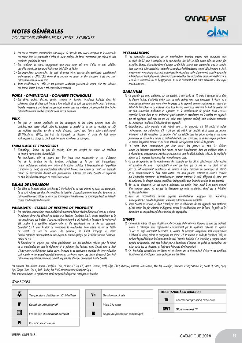
99CATALOGUE 2018
Sect
ion
1
IMPRIMÉ: JANVIER 2018
1 - Les prix et conditions commerciales sont acceptés dès lors de notre accusé réception de la commande par retour écrit. La commande d’achat du client implique de facto l’acceptation par celui-ci de nos conditions générales de vente. 2 - Les conditions et autres engagements que nous avons pris avec l'offre ne sont valables que si la commission comprend tout ce qui fait l'objet de l'offre. 3 - Les propositions commerciales, les devis et autres offres commerciales spécifiques appartiennent exclusivement à CANALPLAST Group et ne pourront en aucun cas être divulguées à des tiers sans autorisation écrite de notre part. 4 - Toute modification de l'offre et des présentes conditions générales de ventes, doit être indiquée par écrit et limitée à ce qui a été expressément convenu.
POIDS - DIMENSIONS - DONNEES TECHNIQUES 5 - Les devis, projets, dessins, photos, couleurs et données techniques indiqués dans les catalogues, listes et offres sont fournis à titre indicatif et ne sont pas contractuelles pour l'entreprise, laquelle se réserve le droit de les changer à tout moment pour une meilleure précision produit. Pour toutes autres informations, veuillez contacter notre service technique
PRIX 6 - Les prix et remises appliqués sur les catalogues et les offres peuvent subir des variations sans aucun préavis selon les exigences du marché ou en cas de variations du coût des matières premières ou de la main d'oeuvre. Ceux-ci sont franco notre Etablissement (EXW-Incoterms 2010), les frais de transport, de douane, et droits de tout genre sont toujours à la charge du client, sauf tout autre accord écrit de notre part.
EMBALLAGE ET TRANSPORT 7 - L’emballage, facturé au prix de revient, n'est pas accepté en retour. La condition de retour à notre société s’entend EXW. Par conséquent, elle ne pourra pas être tenue pour responsable en cas d’absence lors de la livraison ou de livraisons irrégulières de la part des transporteurs; restant explicitement entendu que, même si la société contribue à l'organisation de l'expédition à l’adresse du client, les marchandises retourneront toujours aux risques du client. Les éventuels retours de marchandise devront être préalablement autorisés par notre Société et dépourvus de tous frais dans les entrepôts de notre Etablissement.
DELAIS DE LIVRAISON 8 - Les délais de livraisons prévus sont donnés à titre indicatif et ne nous engage en aucun cas légalement. Ils ne sont valables que dans des conditions de travail et d’approvisionnement normales. En aucun cas notre société ne sera obligée de verser des dommages et intérêts en cas de dommages directs ou indirects causés par des retards de livraison.
PAIEMENTS - CLAUSE DE RESERVE DE PROPRIETE 9 - Les conditions commerciales et les modalités de paiement doivent résulter d’un accord écrit ou, à défaut, le paiement devra être effectué en espèce à la livraison. Canalplast S.p.A. restera propriétaire de la marchandise tant que le client n'aura pas entièrement payé le prix indiqué sur la facture, la vente ayant été conclue à la condition indiquée ci-dessus. Par conséquent, en cas de non paiement, Canalplast S.p.A. aura le droit de revendiquer la marchandise livrée même en cas de faillite du client. En cas de retards de paiement, le Client s'engage à verser l'intérêt moratoire correspondant au taux moyen du marché appliqué par les Etablissements Financiers, majoré de 4%. Si l'acquéreur ne respecte pas, même partiellement, une des conditions prévues pour le retrait de la marchandise ou pour le règlement et le paiement des factures, notre Société aura le droit d'interrompre immédiatement toutes autres livraisons et se considérera exonérée de toute obligation contractuelle, restant entendu son droit éventuel en cas de non respect des clauses du contrat. Sauf tout autre accord explicite les paiements doivent toujours être effectués directement à notre Société.
RECLAMATIONS 10 - Les éventuelles réclamations sur les marchandises fournies devront être transmises dans un délais de 12 jours à réception de la marchandise. Une fois ce délai écoulé elles ne seront plus acceptées. Chaque réclamation devra s'appuyer sur des faits concrets pour pouvoir être prise en compte. Nous pourrons à notre appréciation reprendre ou remplacer l'article présenté comme défectueux par le client, mais nous ne reconnaîtrons aucun frais engagé pour des réparations ou des changements apportés sans notre autorisation. Les éventuelles contestations sur chaque expédition de marchandise n'auront aucun effet ni sur le reste de la commande ou de l'engagement, ni sur le paiement d'une autre marchandise déjà reçue et non contestée.
GARANTIES 11 - La garantie que nous appliquons sur nos produits a une durée de 12 mois à compter de la date de chaque facture, c'est-à-dire qu'au cours de cette période nous nous engageons à réparer ou à remplacer gratuitement dans notre atelier les pièces ou les appareils devenus inutilisables en raison d'un défaut de fabrication ou du matériel. Dans tous les cas, nous nous réservons le droit de décider s'il est plus convenable d'effectuer la réparation ou le remplacement du produit. Nous excluons cependant l'envoi d'un de nos techniciens pour contrôler les installations sur lesquelles nos appareils ont été appliqués, sauf pour les cas où, selon notre jugement exclusif, nous estimons nécessaire de contrôler les conditions d'utilisation de nos appareils. 12 - Naturellement, notre garantie n'est valable que si les appareils ont été posés et traités conformément aux instructions, s'ils n'ont pas été altérés ou modifiés et si toutes les normes techniques ont été respectées. La garantie n'est pas valable pour les pièces sujettes à une usure prématurée en raison de la nature du matériel dont elles sont composées ou de leur emploi spécifique. De même, les pannes dérivant d'une usure naturelle sont également exclues de la garantie. 13 - Le client devra communiquer par écrit toutes les pannes et tous les défauts relevés en indiquant exactement leur nature, et nous interviendront, dans les meilleurs délais, à la réparation et remplacement selon les circonstances et dans les délais indiqués ci-dessus. Le matériel à réparer ou à remplacer devra nous être retourné en port payé. 14 - En cas de réparation ou de remplacement des appareils ou des pièces défectueuses, notre Société est exonérée de toute responsabilité à quel que titre que ce soit, et le client est de part ce fait entièrement désintéressé et renonce à toute demande de dommages et intérêts et de remboursement de frais. Dans certains cas nous pouvons autoriser le client à pourvoir aux éventuelles réparations ou remplacements, restant entendue la seule obligation de notre part de rembourser les charges directes considérées indispensables pour la remise en état de nos appareils. 15 -En cas de divergences sur des aspects techniques, les parties feront appel à un expert nommé d'un commun accord ou, en cas de divergence sur cette nomination, choisi par le Président du Tribunal de Milan. 16 - Nous ne reconnaîtrons aucune dépense éventuellement engagée par l'Acquéreur, même pendant la période de garantie, sans notre autorisation écrite préalable. 17 - Notre Société se réserve le droit d'employer dans la fabrication de ses appareils tous matériaux qu'elle estime les plus adaptés et d'apporter toutes les modifications dans la forme, le poids ou les dimensions de ses produits qu'elle estime les plus appropriées.
LITIGES 18 - Les contrats, même s'ils sont stipulés avec des Sociétés et des citoyens étrangers ou pour des matériels fournis à l'étranger, sont réglementés exclusivement par le législation italienne en vigueur. En cas de litige concernant l'exécution du contrat, la juridiction compétente sera exclusivement le Tribunal de Milan, même en dérogation des articles 31 et suivants du Code de Procédure Civile, en excluant la possibilité pour le Commettant de saisir l'Autorité Judiciaire d'un autre lieu, y compris comme garantie ou connexité, mais sauf le droit pour le fournisseur d'intenter, en qualité de demandeur, une action sur le lieu de résidence, en Italie ou à l'étranger, du Commettant. 19 - Les éventuelles contestations ne dispensent absolument pas le Commettant d'observer les conditions de paiement et n'impliquent aucun prolongement des délais.
Les marques Olan, Alofree, Articon, Canalplast, CaZn, CP Box, CP Din, CZE, Desko, Dominio, Ecabl, Edge, FiloCP, Hypogeo, Lineadin, Mini System, Mini Tris, Monolyto, Simmetris 2120, Sistema Tris, Sonda CP, Sotto, Spiro, Sys45Rapid, Talpa, Tipo G, Triall, Triedra, Tris 2000 appartiennent à Canalplast S.p.A.Sauf notre autorisation, la reproduction totale ou partielle du présent catalogue est interdite.
noteS GénéraLeScONDitiONS GéNéRaLES DE vENtE - SYMBOLES
Temperature d’utilisation C° Min/Max
IP degré de protection iP
Protection d'isolement complet
PI Pouvoir de coupure
Vn tension nominale
T Mise à la terre
IK degré de protection mécanique
RéSiStAnCE à lA CHAlEUR
TB Thermocompression avec balle
GWT Glow wire test °C
SYMBOLES

canalplast s.p.a.Via Tolstoi, 65 - 20812 limbiate (MB) Italy
Phone +39 02990642.1 - Fax + 39 0299055900www.canalplast.it - www.canalplast.eu
e-mail: [email protected]
olan srl Via Marconi, 39 - 20812 limbiate (MB) Italy
Phone +39 0299055317 - Fax +39 0299488724 www.olansrl.com
e-mail: [email protected]