cas e f i le copy - nasa · cas e f i le copy ... the emergency shutdown procedure employed,...
TRANSCRIPT

NASA TECHNICAL
MEMORANDUM
NASA TM X- .52730
0ee_
IX
_EI=,-
<:
<Z
CAS E F I LECOPY
EXPERIMENTALINVESTIGATIONOF SNAP-8
SHUTDOWNCHARACTERISTICS
by Thomas P. Hecker
Lewis Research Center
Cleveland, Ohio
November 1969
https://ntrs.nasa.gov/search.jsp?R=19700003783 2018-07-13T02:06:15+00:00Z

This information is being published in prelimi-
nary form in order to expedite its early release.
EXPERIMENTAL INVESTIGATION OF SNAP-8
SHUTDOWN CHARACTERISTICS
by Thomas P. Hecker
Lewis Research Center
Cleveland, Ohio
NATIONAL AERONAUTICS AND SPACE ADMINISTRATION

ABSTRACT
An experimental study of the shutdown of s SNAP-8 power conversion
system was conducted to determine the transient response of the system
to two shutdown modes, viz., a normal shutdown and an emergency shutdown.
For the emergency shutdown, a failure of the condenser-coolant pump was
simulated. Neither mode of shutdown resulted in parametric excursions
beyond the limit considered safe for the components. Transient data
for three normal shutdown tests and three emergency shutdown tests are
presented.


co
_I_uoI
r_
EXPERIMENTAL INVESTIGATION OF SNAP-8
SHUTDOWN CHARACTERISTICS
By Thomas P. Hecker
Lewis Research Center
SUMMARY
An experimental study of the shutdown of a SNAP-8 power conversion
system was conducted to determine the transient response of the system to
normal and emergency shutdown modes. The normal shutdown was conducted
from the system's self-sustaining mercury flow rate of 6600 ibs/hr. Results
of the normal shutdown indicate that the system can be repeatably shut down
in such a way as to insure restart capability even in zero gravity. For
the emergency shutdown, a failure of the condenser coolant pump was simu-
lated. This resulted in a rapid increase of pressure in the mercury con-
denser. The emergency shutdown procedure employed, however, limited this
pressure to values eonsidered safe for the condenser.
INTRODUCTION
SNAP-8 is a nuclear auxiliary power system, capable of producing more
than 35 kilowatts of usable electric power. It is a four-loop system utilizing
three working fluids. A nuclear reactor in the primary loop supplies thermal
energy to NaK (the eutectic mixture of sodium and potassium). The thermal
energy is transferred to a mercury loop by means of a NaK-to-mercury heat
exchanger (or boiler). The mercury vaporized in the boiler drives the turbine-
alternator; it is then liquefied in the condenser and pumped back to the
boiler. The condenser's waste heat is removed by the NaK of the heat-rejection
loop and is rejected to space by a radiator. The fourth loop contains a
polyphenyl-ether oil mixture (NPBE) that lubricates and cools the turbine-
alternator, the mercury-pump-motor assembly bearings, and cools the NaK
pumps and electrical equipment. All four loops use centifugal pumps driven
by eleetric motors, the power for whieh is generated by the turbine-alternator.
It is intended that the SNAP-8 system have shutdown and restart capa-
bility for long-term use in space. Shutdowns must not impair the operability
of the components for further long-term service. Also, shutdowns must be
accomplished in a way that puts the system in the proper condition for sub-
sequent startup. One important implication of this is that mercury inventory
must be withdrawn from the power loop during shutdown in order to ensure
successful injection-starting of the turbine-alternator. The detailed pro-
cedures used in SNAP-8 startup are discussed in references i, 2, and 3.
In order to evaluate the proposed shutdown procedures, shutdown tests were
included during extensive startup testing of SNAP-8 at Lewis ResearchCenter. The tests were conducted with a full-scale SNAP-8 power conversion
system using an electric heater and a computer to simulate the reactor.
This report presents the preliminary results of the shutdown tests. The
transient data obtained from three normal system shutdowns and three emer-
gency shutdowns are presented and discussed herein.
DESCRIPTION OF SNAP-8 TEST SYSTEM AND INSTRUMENTATION
Test System
The SNAP-8 test system included all of the major SNAP-8 components
except the reactor and radiator. The test system was assembled in a way
that permits easy access to the components and allows for system instru-
mentation. Two computer-controlled, air-cooled heat exchangers, were used
to simulate the radiator. A computer-controlled electric heater in the
primary loop simulated the reactor (ref. 4). T6e SNAP-8 test system is
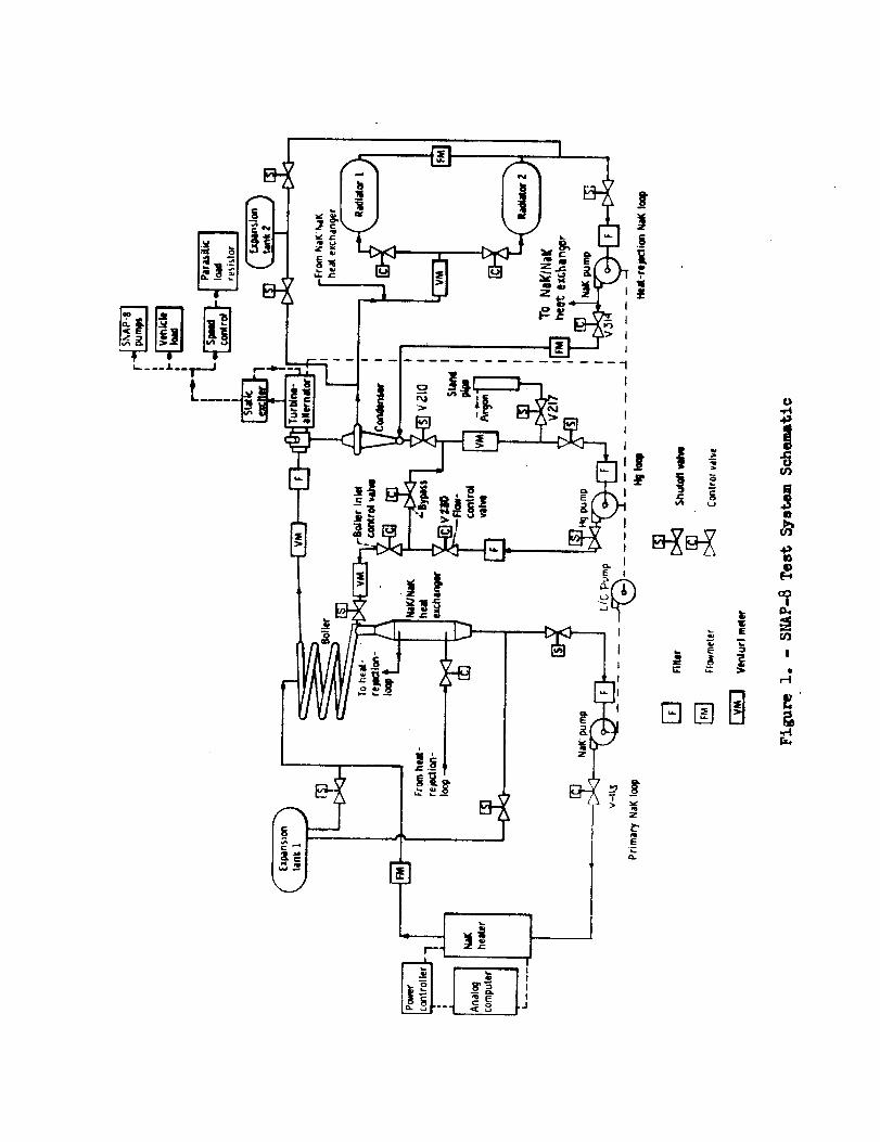
described in reference 5. A schematic diagram of the test system, showing
the four loops, is shown in figure i.
Several controls pertinent to shutdown are indicated in figure 1.
The mercury-loop flow-control valve is a computer-controlled electro-
hydraulic valve [V-2B0) on the discharge of the mercury pump. A flow
feedback signal was used to control positioning of the valve. The control
circuit utilized a combination of open loop, integral, and proportional
controls. The condensing pressure in the mercury condenser was cont_olled
by varying the flow rate of the heat-rejection-loop NaK in a dead-band
mode. The dead-band control sensed the condensing pressure and converted
it into a command signal to activate the heat-rejection-loop flow-control
valve (V-314) shown in figure i. The standpipe was used as the mercury
injection reservoir during startup and also was used to withdraw inventory
in the shutdown tests. The standpipe gas pressure was set by a hand-adjusted
regulator and could be varied from 0 to 50 psia. The NaK-to-NaK heat ex-
changer in the primary loop transferred heat from the primary loop to the
heat-rejection loop by means of an auxiliary loop, before the startup and
after the shutdown of the mercury loop. Flow in the auxiliary loop was
controlled by valve V-II7 (fig. i). A variable-frequency motor-generator
set was used as an auxiliary power supply for the pumps.
Instrumentation
Instrumentation used for the shutdown investigations consisted of:
thermocouples, electro-magnetic flowmeters, pressure transducers, voltage,
current, and power transducers, flow venturis, and magnetic speed pickups.
A complete description of the instrumentation is given in reference 6.
The data presented were partially acquired from control-room strip-chart recorders, and supplemented by data from a computerized digital datasystem. The digital data system scanned and recorded 400 channels of dataevery 11.43 seeonds, when in operation.
PROCEDURE
Normal Shutdown
In the normal shutdown, the mercury flow rate was first ramped from the
rated level of 12,300 ib/hr to the self-sustaining level of 6,600 ibs/hr
in a period of 900 seconds. Since this throttling of the system was in a
low quasi-steady manner, it is not considered a pertinent part of the shut-
down procedures. At this self-sustaining flow, level of 6,600 ibs/hr, all
four pumps were receiving their power from the alternator, and condensing
pressure was being maintained by the dead-band control of the heat-rejection
loop. When the system had settled out at the 6,600 ib/hr flow, the mercury
flow rate was then ramped down to a value of 400 ibs/hr in a period of 150
seconds. Condenser coolant NaK flow rate was controlled by the dead-band
control throughout the shutdown to maintain condensing pressure in the range
of ii to 14 psia. As the turbine-alternator frequency fell to 300 hertz,
the lift-off seals were lowered into contact (seated) and the lubricant-
coolant flow to the bearings was stopped. When the turbine-alternator
frequency decreased to 220 hertz, the pumps were transferred to the auxiliary
power supply. At a mercury flow rate of 400 ibs/hr, valve V 217 (fig. i)
was opened so that the mercury inventory could be transferred from the con-
denser to the standpipe. To accomplish this transfer, the mercury flow
rate was held at 400 ibs/hr for 160 seconds with the mercury pump running
on 220-hertz auxiliary power. During this transfer period, the standpipe
gas pressure was regulated in an attempt to simulate a zero-gravity eon-
dition; argon gas pressure above the liquid mercury level in the standpipe
was maintained equal to the hydrostatie head of liquid mercury between the
liquid heads in the condenser and in the standpipe. After the inventory
transfer was completed, the mercury-flow-control valve was shut, flow was
established in the auxiliary loop, and the condenser outlet valve (V-210)
closed. The heat-rejection-loop flow control valve was then opened to the
initial position for the next startup. The reaetor simulator control was
in the normal dead-band mode throughout the shutdown.
Emergency Shutdown
For the emergency shutdowns, a failure of the heat-rejection-loop pump
was simulated. The pumps were receiving their power from the auxiliary power
supply during both emergency shutdowns presented in this report. The first
emergency shutdown presented was executed from a mercury flow rate of 6,800
ibs/hr, with all of the alternator power going to the parasitic load of the
speed control. The second emergency shutdown presented was conducted from
a mercury flow rate of 12,300 ibs/hr with 15 kilowatts of external load on
the alternator to simulate the power requirement of the four pumps. Theshutdown was initiated by shutting off heat-rejection-loop NaK flow to thecondenser by means of valve V-BI4 (fig. i), which took about one second tocompletely close. When the condenser coolant flow had stopped, the mercuryflow control valve (V-230) was ramped by the computer, in about one second,to a small opening and then closed manually. Inventory withdrawal was alsoinitiated when the condenser-coolant flow stopped, and the standpipe gaspressure was regulated as in the normal shutdown to simulate a zero-gravitycondition.
In the shutdown from the rated condition of 12,300 ibs/hr mercury flow,the primary loop flow was decreased to 23,000 ibs/hr, after the mercuryflow was stopped, by throttling valve V-II5 (primary loop flow control valve).This was done in order to simulate the primary pump's being switched to the
auxiliary power supply during shutdown. For each emergency shutdown test,
the reactor-simulator control was in the normal dead-band mode. The auxiliary-
loop flow was started about 4½ minutes after the mercury flow was stopped.
RESULTS AND DISCUSSION
Normal Shutdown
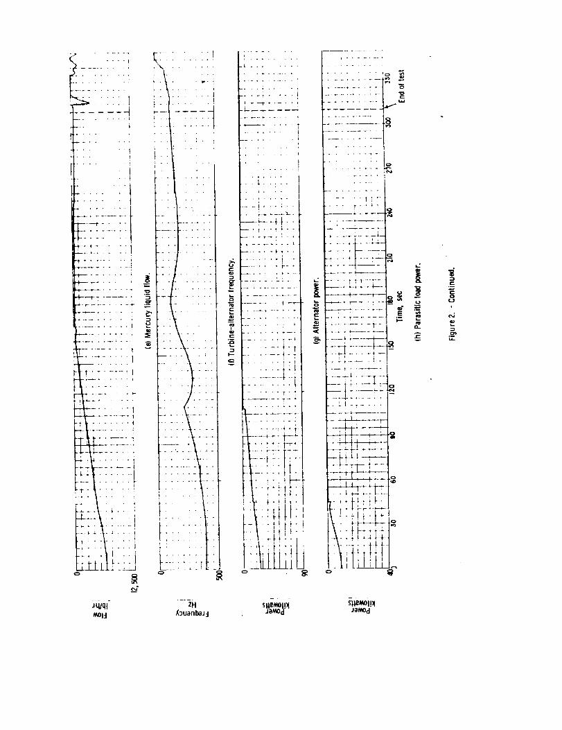
Time-history recordings of the pertinent variables for a normal shut-
down are shown in figure 2. All four pumps were receiving power from the
turbine-alternator and decelerated with it until the frequency reached 220
hertz, at which frequency all four pumps were switched simultaneously to the
auxiliary power supply operating at 220 hertz. This transfer of the pumps
was smooth and produced no significant disturbances of pump speeds or flows.
This is illustrated by the recordings of the primary, mercury, and heat-
rejection loop flows. Alternator frequency increased from 220 hertz to
300 hertl after the electrical load of the pumps was removed. As shown
in figure 2(a), the mercury liquid flow ramp was smooth, even though the
mercury pump speed was decreasing during the ramp.
The turbine began to decelerate (fig. 2(b)) as the boiler inlet pressure
reached 300 psia and the boiler outlet pressure was 130 psia (figs. 2(c) and
2(d)). Alternator power output and parasitic load of the speed control
during turbine deceleration are shown in figures 2(g) and 2(h). The turbine
ceased to rotate about B40 seconds after initiation of the shutdown process.
The bearing lubricant flow was stopped and the lift-off seals applied at
300 hertz, so the total time of lift-off seal contact was 280 seconds for
this shutdown.
Throughout the shutdown transient, condensing pressure was regulated
by the dead-band control of the heat-rejection-loop NaK flow (fig. 2(j)).
The 400 ib/hr mercury flow rate, combined with a near-zero heat-rejection-
loop NaK flow rate, maintained the condensing pressure between 5 and 14 psia
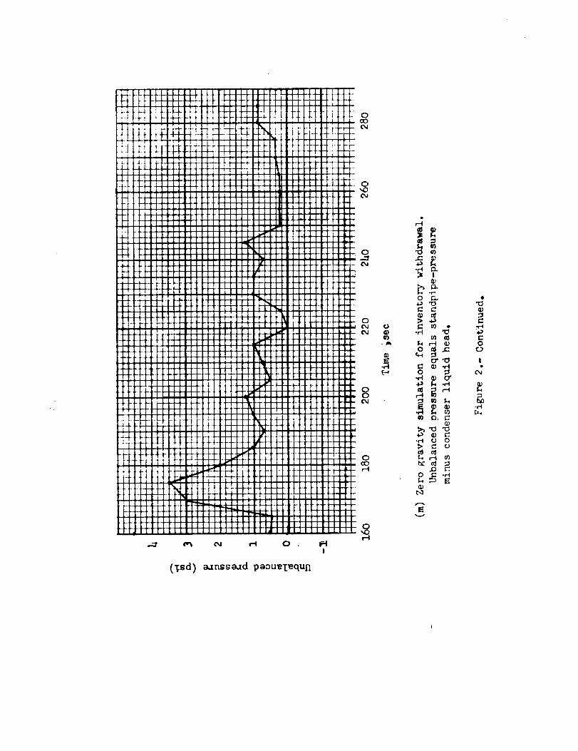
during the condenser inventory withdrawal period. The standpipe gas pressure
was manually regulated during the shutdown in an attempt to simulate a zero-
gravity condition for the withdrawal process. The success of this simulation
4

can be ascertained from figure 2(_, showing the difference between stand-
pipe pressure and the condenser liquid head. The maximum variation between
the standpipe pressure and the condenser liquid head was 3.5 psi, with the
greater pressure in the standpipe. Throughout the shutdown, the liquid
head in the condenser never exceeded the standpipe pressure. This shows
that the zero-gravity simulation during the shutdown was very close to
the desired conditions and the condenser pressure had to work against the
standpipe pressure in order to move the mercury into the standpipe. During
this period, 5q pounds of mercury were transferred to the standpipe, repre-
senting i00 percent of the inventory in the boiler and condenser before
the shutdown.
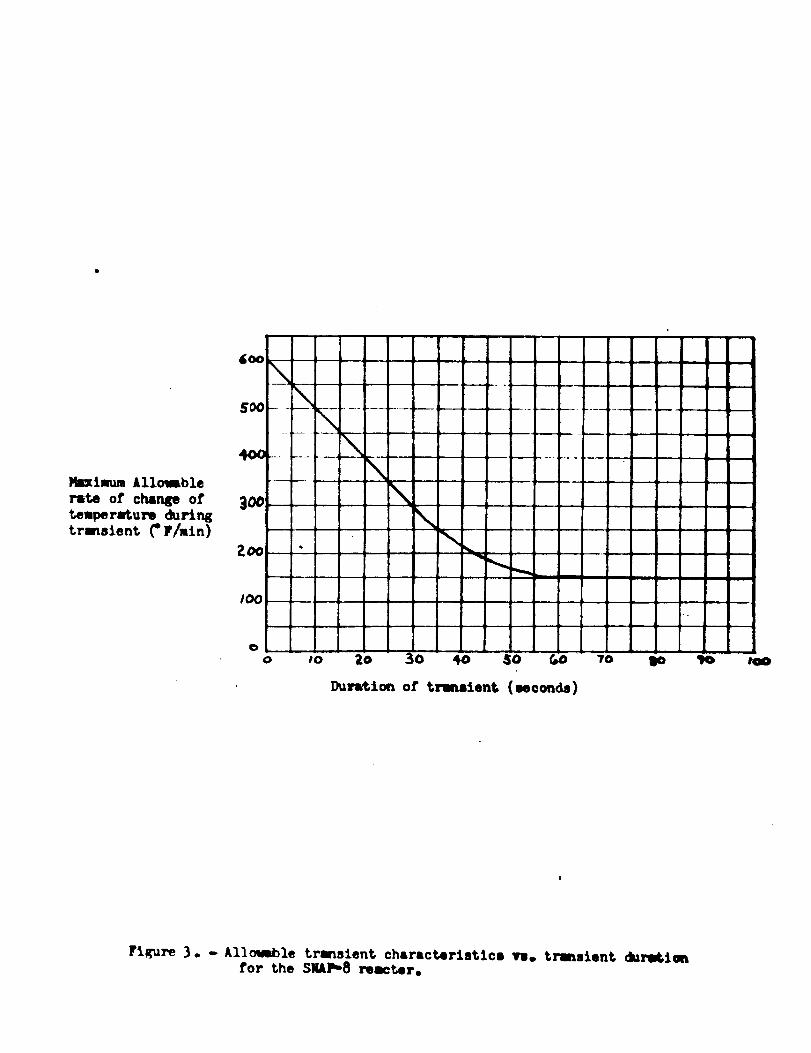
The primary-loop transients during the normal shutdown were minimal.
As shown in figure 2(o), the primary loop flow rate reached 26,000 ibs/hr
as the pump was transferred to the 220-hertz auxiliary power unit. The
reactor simulator inlet temperature increased from 1180 ° F to 1290 ° F, with
a maximum rate of change of 40 ° F/minute, which lasted for 80 seconds
(fig. 2(p)). This was well within the reactor's envelope for acceptable
rate of temperature change, as shown in figure 3. The reactor-simulator
outlet temperature (fig. 2(q)) increased from 1280 ° F to only 1307 ° F during
the shutdown, showing that the reactor-simulator power reduetion was suf-
ficiently fast. The power reduction was due to the inherent temperature-
feedbaek of the reactor-simulator. No action of the control was involved,
since the outlet temperature remained within the control deadband of 1280 ° Fto 1320 ° F.
Emergency Shutdowns
Shutdown from 6_0 ibs/hr mercury flow. - During the emergency shutdown
test from a mercury flow rate of 6,600 ibs/hr, the excursion_of all the
variables were within the limit considered safe for the syste_ and components.
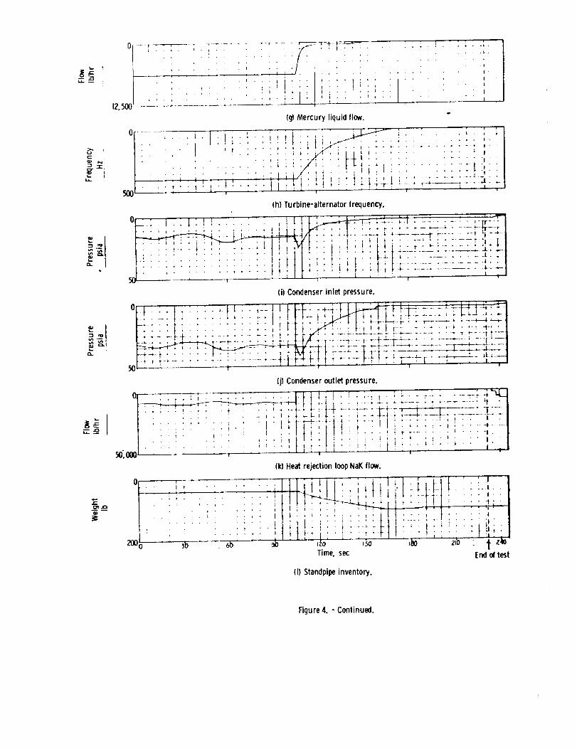
The variables are shown in figure 4 for this shutdown. All four pumps were
operating on a q00-hertz auxiliary power supply and were running at rated
speed throughout the shutdown. The fast deceleration of the turbine (fig. 4(b))
was due to the quick stoppage of mercury flow (fig. q(a)) and also the high
back pressure on the turbine caused by the high condensing pressure. The
turbine rotated for 60 seconds after the mercury flow was stopped, and 50
seconds of that time was with the lift-off seals seated and the bearing-
lubricant flow stopped. The decay_rates of the boiler pressures and alter-
nator power output are shown in figures 4(c) through 4(f).
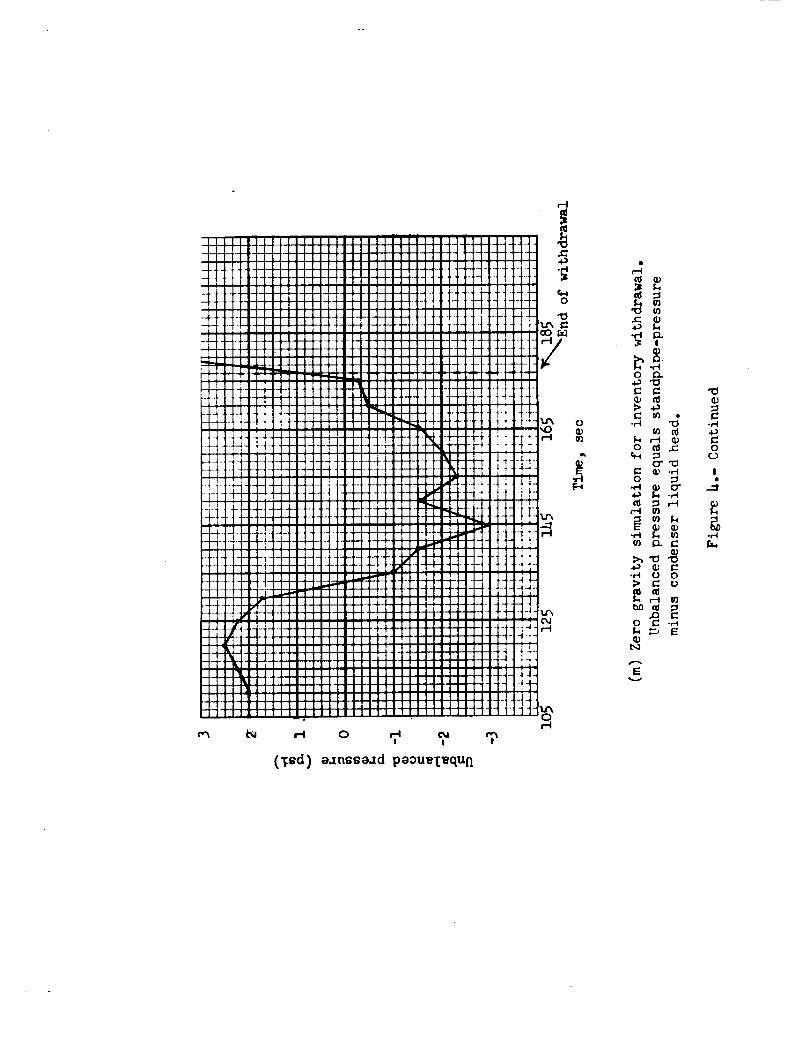
Condensing pressure increased from 15 psia to a maximum of 24 psia
during the shutdown because of the stoppage of the condenser coolant flow
(figs. 4(i) and q(k)). Figure q(m) shows the zero-gravity simulation during
this shutdown. Due to the rapid shutdown, the zero-gravity simulation was
very difficult to achieve. The maximum difference between the standpipe
pressure and the condenser liquid head was 3 psi with the greater pressure
being the condenser liquid head. This assisted the condensing pressure in
moving the mercury into the standpipe during this period, which does not

accurately simulate zero-gravity. Of the mercury inventory in the condenserand boiler, only 66 percent was transferred to the standpipe because,!throughhuman intervention, the condenser mercury outlet valve (V-210) was closedearly; this early valve closure makes irrelevant the G6-percent mercurywithdrawal during this shutdown. In another test from 8,600 ib/hr mercuryflow, 97 percent of the boiler and eondenser inventories was withdrawn.In this shutdown the condenser coolant/flow was ramped to 0 in i0 secondsrather than being abruptly stopped in one second; however, it is believedthat the inventory withdrawal portion was representative of the emergencyshutdown test. This shows that most of the boiler and condenser inventoriescan be withdrawn even in an emergency shutdown test from the self-sustainingmercury flow of G,600 ibs/hr.
The primary-loop transients during this emergency shutdown were signifi-cant, but still within the operating envelope of the reactor (fig. 3).Reactor-simulator inlet temperature increased from 1178° F to 1287° F (fig.4(r)), and the maximumrate of ehange was 400° F per minute, which lasted fori0 seconds. These values are below the reactor operating constraints shownin figure B. Reactor-simulator outlet temperature increased from 1275° Fto 1298° F during the shutdown (fig. 4(s)). The auxiliary loop NaN flowwas not established until well after the shutdown test and thus no heatwas dissipated from the primary loop to the heat-rejection loop during theportio D of the transient shown. The reactor simulator control was in thedead-band mode during the shutdown; however, no control action was required.
Shutdown from rated mercury flow. - The simulated failure of the heat-
rejection pump with the mercury flow at the rated value of 12,300 ibs/hr
was a mope severe test of the emergency shutdown procedure. This shutdown
is shown in figure 5. All four pumps were running on the auxiliary power
supply at 400 hertz throughout the shutdown. 15 kW of external load were
applied to the alternator in order to simulate the power requirement of
the pumps. The fast deceleration of the turbine (fig. %(b)) was due to
this external load, the sudden stoppage of mercury flow, and the high turbine
back pressure. The turbine rotated for 50 seconds after the condenser
coolant flow was stopped, and 42 seconds of that time were with the lift-
off seals seated and with no bearing lubricant flow. The decay rates of
the boiler pressures and the alternator power output are shown in figures
5(c) through 5(_.
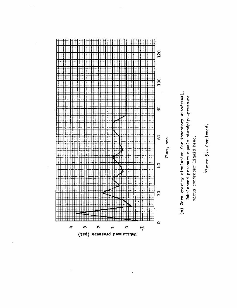
Condensing pressure increased rapidly from 15 to 41 psia (fig. 5(i))
during the shutdown, because of the stoppage of the condenser coolant flow.
However_ a margin of 32 percent below the operational-limit pressure of
60 psia still remained. Condensing pressure then decayed rapidly to about
15 psia from the combined effects of mercury flow stoppage and inventory
withdrawal to the standpipe. The zero-gravity simulation for this shutdown
was very good even though it was a very rapid shutdown. Figure 5(m) shows
the unbalanced pressure during the zero-gravity simulation. The maximum
pressure difference was 3.5 psi with the greater pressure in the standpipe.
For only a very short time was the condenser liquid head greater than the
6

standpipe pressure. Approximately 73 pounds of mercury were withdrawn tothe standpipe, representing 95 percent of the initial boiler and condenser
inventories. Condensing pressure remained at 6 psia for some time due to
the boil-off of the liquid mercury remaining in the boiler.
The primary-loop transients during the rated-power emergency shutdown
were significant, but still within the operating envelope for the reactor
(fig. 3). The reactor-simulator inlet temperature increased from iii0 ° F
to 1300 ° F (fig. 5(r)), and the maximum rate of change was 220 ° F per
minute, for about i0 seconds, values within the range tolerated by the
reaetor. This maximum rate of change of inlet temperature was less than
for the 6,600 ibs/hr emergency shutdown because the primary flow was re-
duced to 23,000 ibs/hr in order to simulate the pump's being switched over
to a 220-hertz auxiliary power supply. Reactor-simulator outlet tempera-
ture rose from 1285 ° F to 1317 ° F (fig. 5(s)) during the shutdown. Once
again the dead-band control was not required to take corrective action.
The auxiliary loop flow was not established until well after the shutdown,
and hence did not affect the primary-loop transients shown.
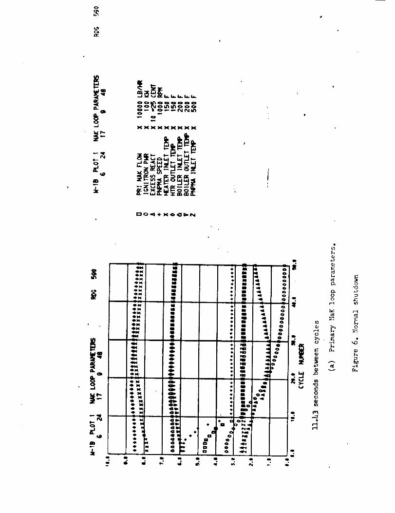
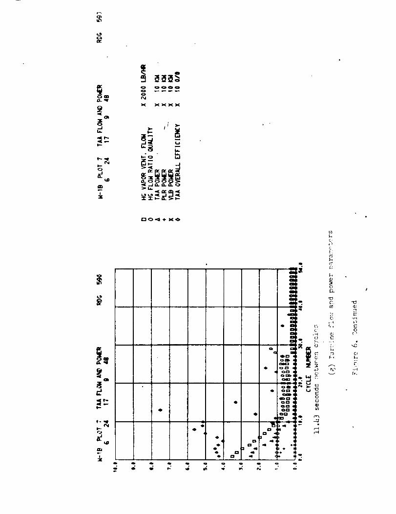
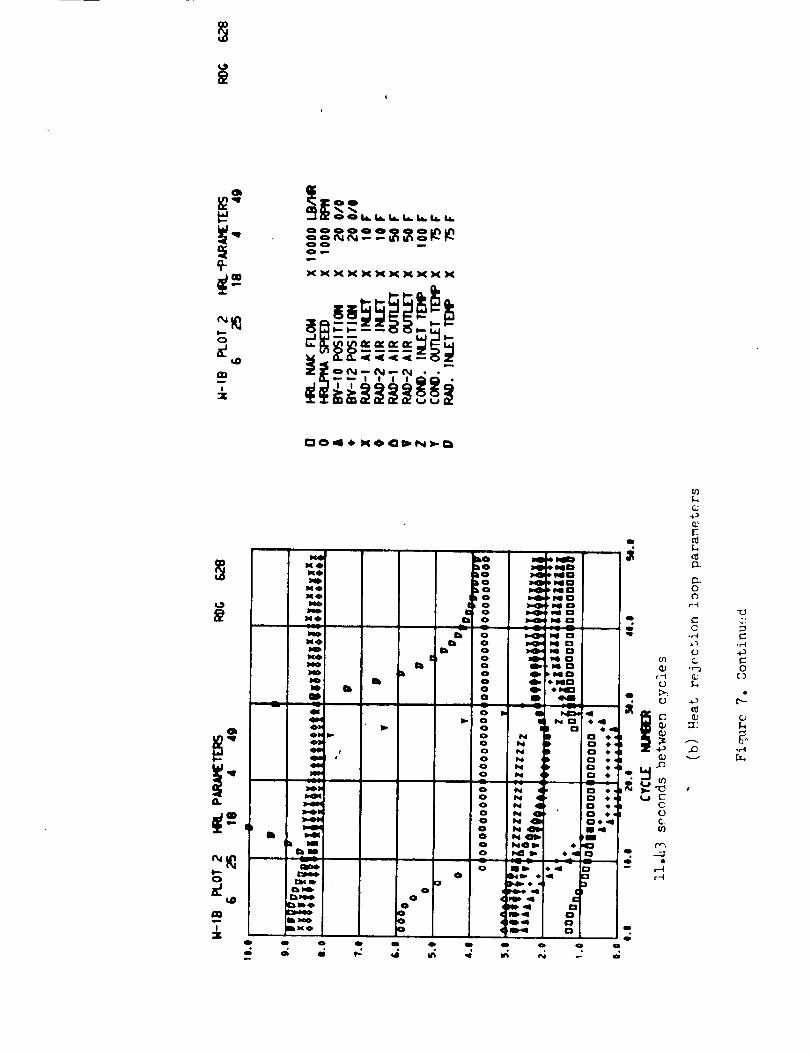
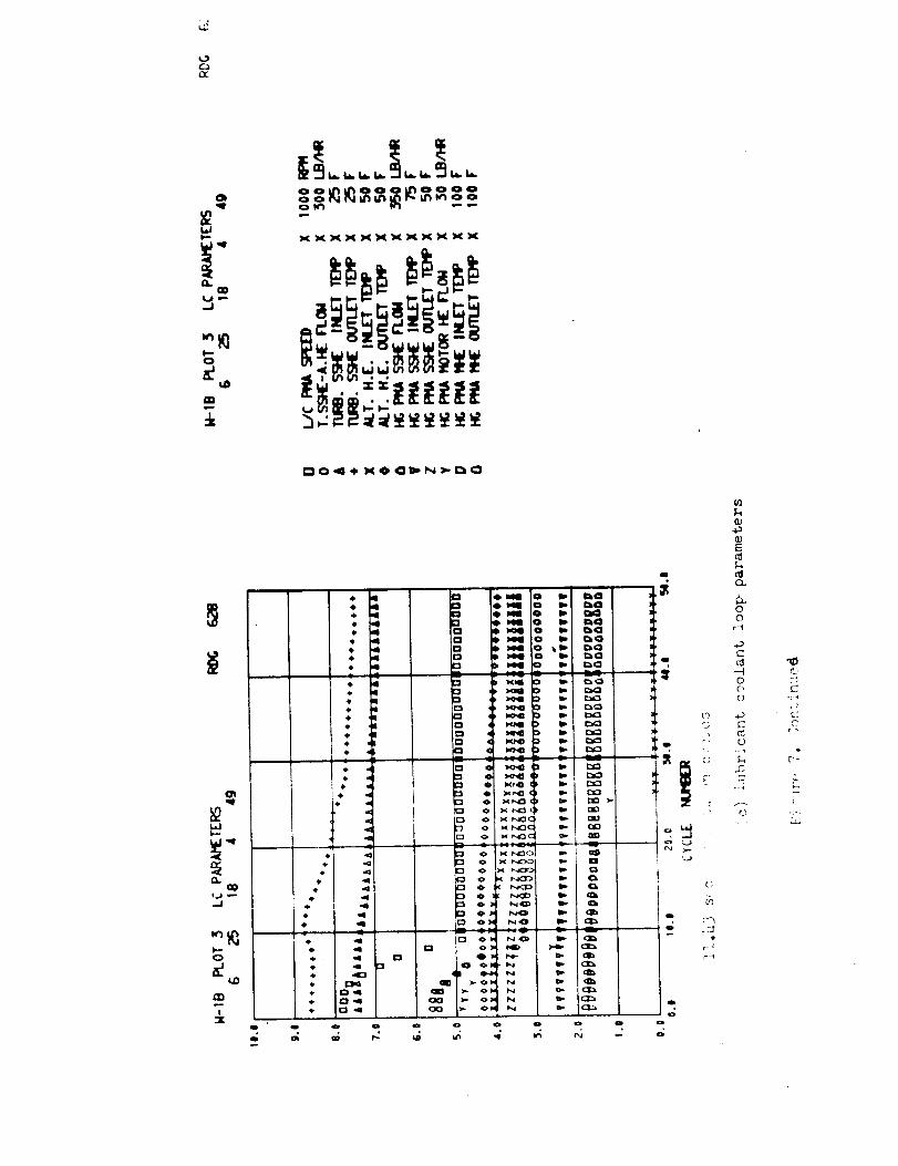
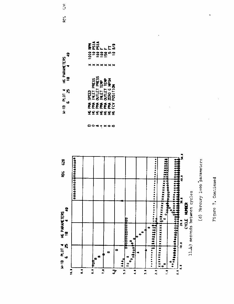
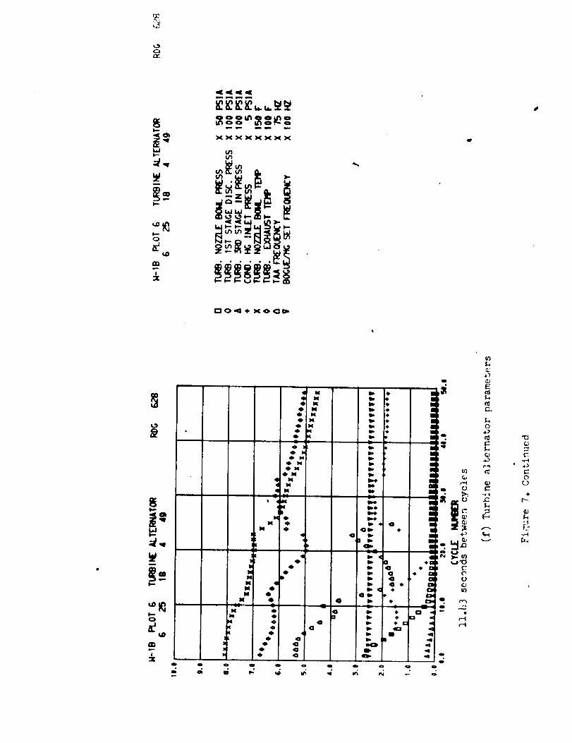
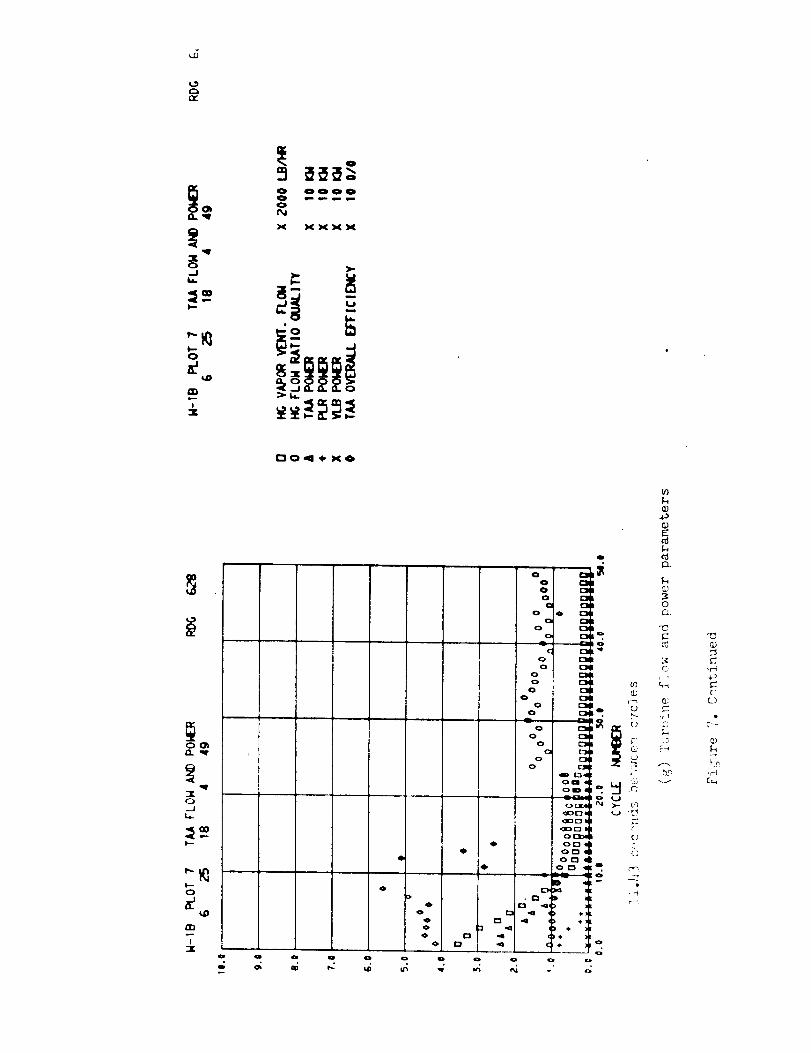
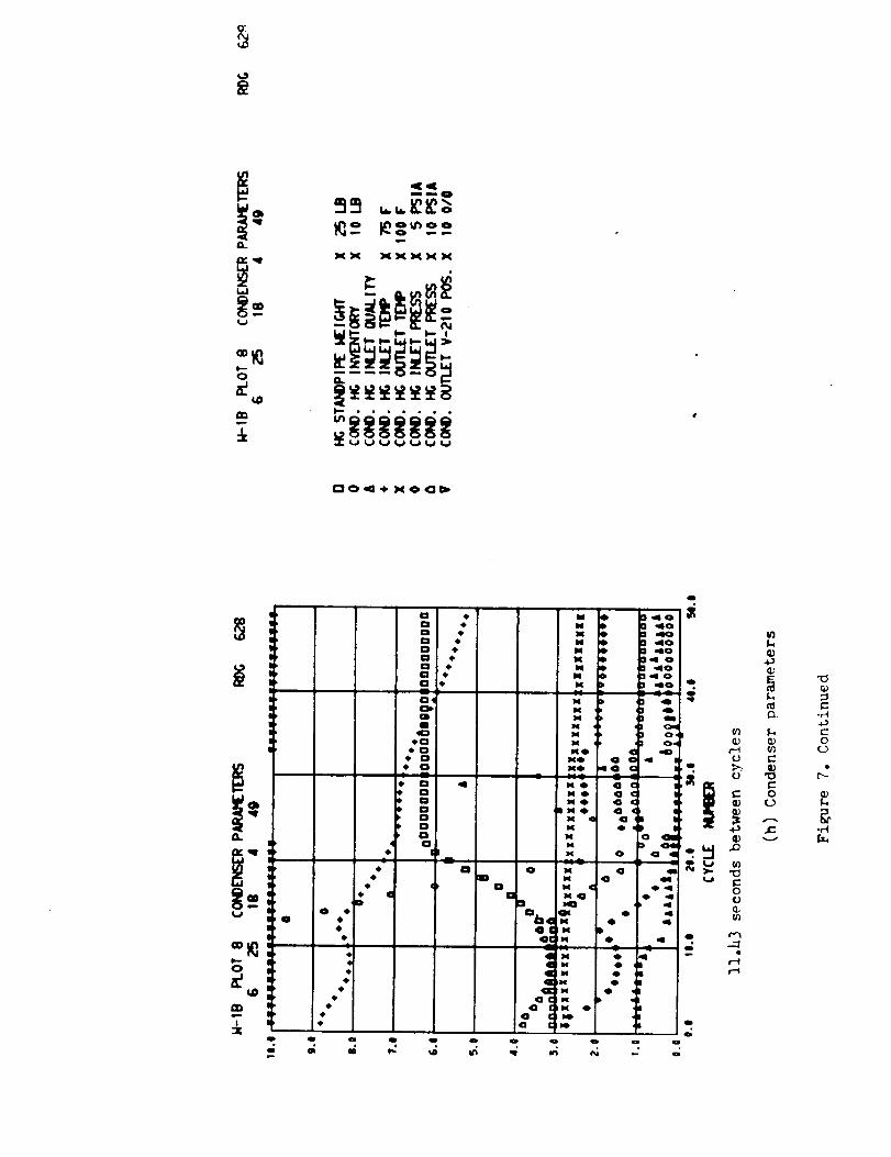
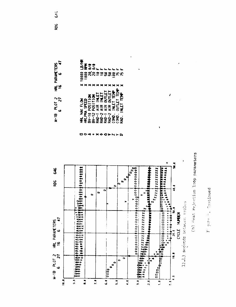
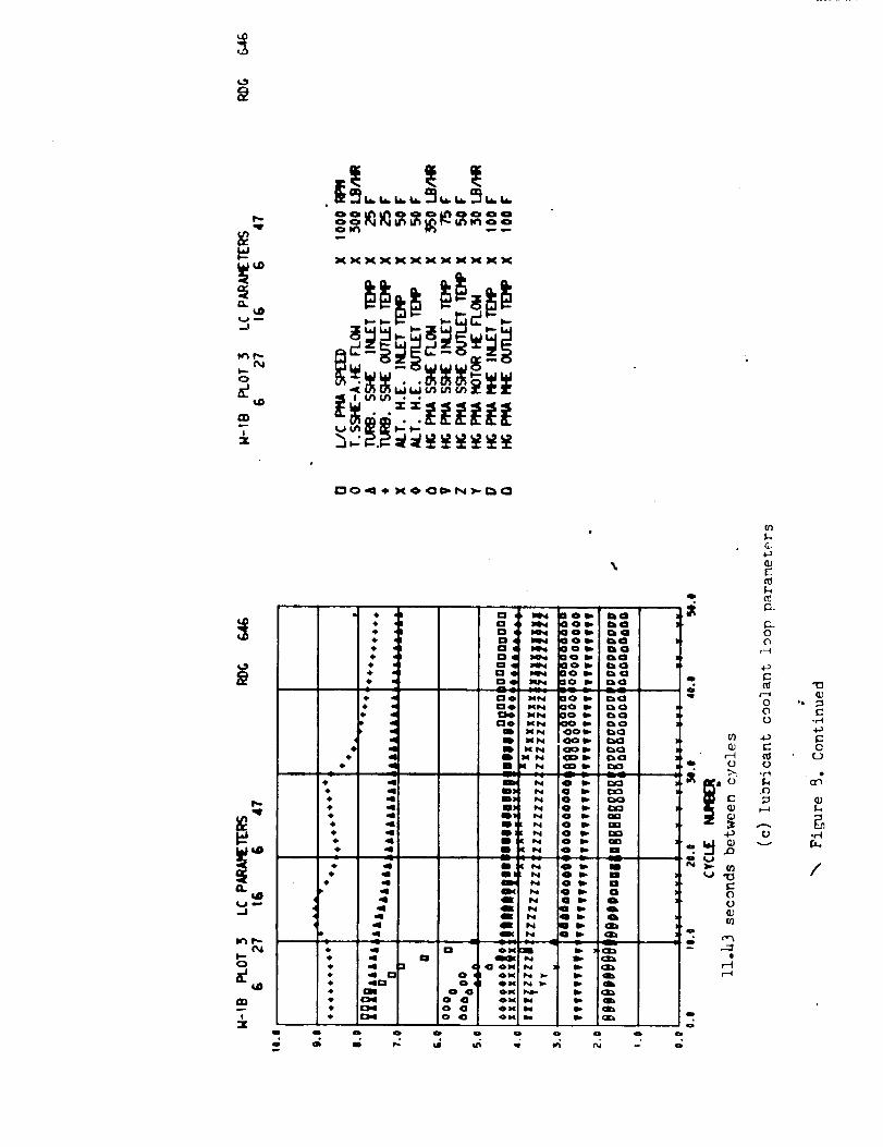
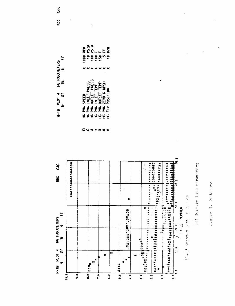
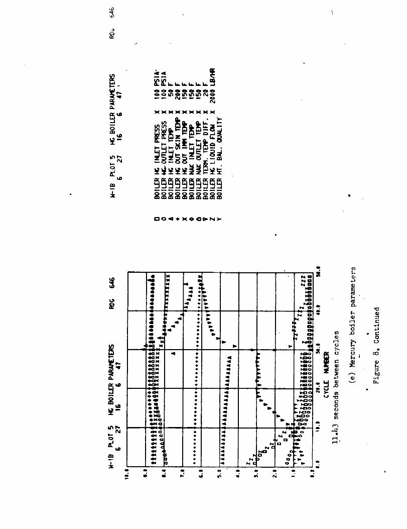
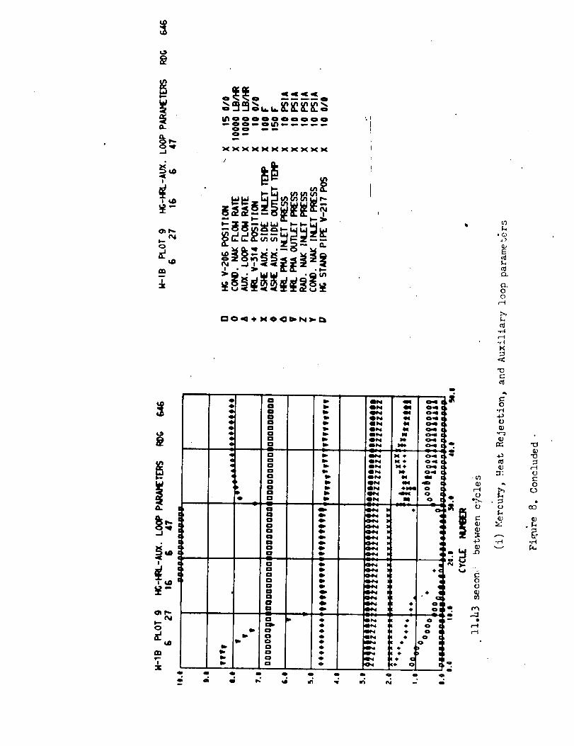
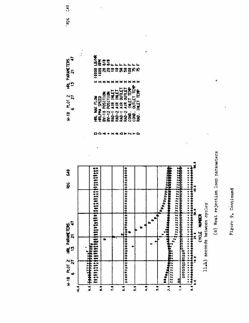
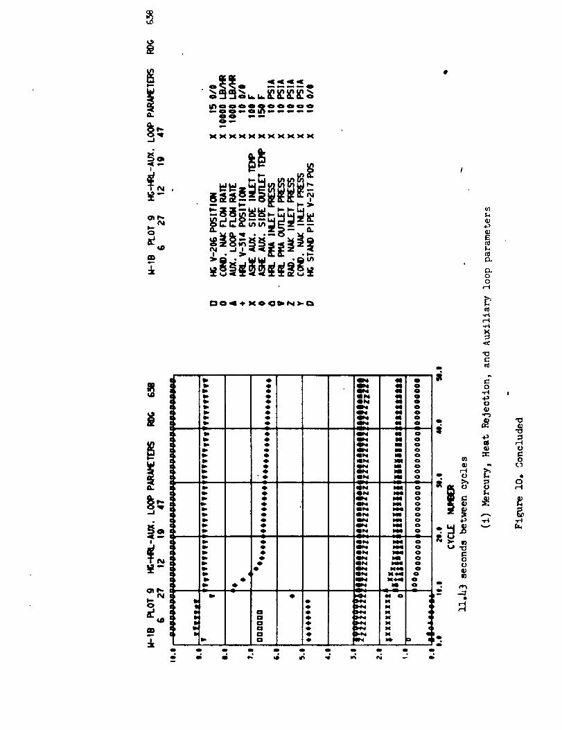
Plots from the digital computer for five of the shutdowns of the SNAP-8
test system are presented in the Appendix. They contain a more complete
set of parameters than the chart-recorder plots. Because the equations
for determining the mercury vapor quality and effieieneies are based on
steady-state conditions, they are to be disregarded in the data plots forthe shutdowns.
SUMMARY OF RESULTS
Both normal and emergency shutdowns of a SNAP-8 system were investi-
gated. The results of a normal shutdown are as follows:
(i) The pumps were switched from the decelerating turbine-alternator
to the auxiliary power supply with no significant disturbances in pump speeds
or flows, and there was no overspeed of the turbine after the pump load
was removed.
(2) Condensing pressure was within acceptable limits during the shut-
down with a 400 ib/hr mercury flow rate, utilizing the dead-band control
of the heat-rejection-loop flow.
(3) Of the boiler and condenser inventories, i00 percent was removed
to an injection reservoir, even under simulated zero-gravity condition.
(4) Reactor simulator temperature transients were minimal with the
reactor simulator control in the normal dead-band mode.
The results of the emergency shutdown are as follows:
(i) Up to 97 percent of the boiler and condenser inventories was with-drawn from the system to an injeetion reservoir under simulated zero-gravity
conditions.
(2) Following a simulated failure of the eondenser-coolant pump, the
maximum pressure in the condenser rose to only 64 percent of the operational
limit on the eondenser. This was accomplished by stopping the flow of
liquid mercury to the boiler and withdrawing inventory through the condenser.\
(3) Reactor simulator temperature transients were well within the
estimated operating limits for the reactor. Fast setback of the reactor
control was not necessary in order to maintain these acceptable transients.
.
.
.
S.
.
REFERENCES
Thollot, Pierre A.; Bloek, Henry B.; and Jefferies, Kent S.:
Experimental Investigation of Reactor-Loop Transients Durin_ Startupof a Simulated SNAP-8 System. NASA TN D-_546, 1968.
Soeder, Ronald H. ; and Lottig, Roy A.: Investigation of Pump Transfer
Frequencies from Auxiliary Power to Alternator Power During Startup
of the SNAP-8 System_ NASA TM X-52712, 1969.
Lottig, Roy A. ; and Soeder, Ronald H. : Investigation of Mercury-
Flow Ramp Rates for Startup of the SNAP-8 System. NASA TM X-52689,1969.
Jefferies, Kent S.; Packe, Donald R.; and Dittrich, Ralph T.: Design
and Performance of a Nuclear Reactor Simulator for Nonnuelear Testing
of Space Power Systems. NASA TN D-4095, 1967.
Maeosko, Robert P.; et al: Performance of an Experimental SNAP-8 Power
Conversion System. NASA TM X-1732, 1969.
Deyo, James N.; and Wintucky, William T.: Instrumentation of a SNAP-8
Simulator Facility. NASA TM X-1525, 1968.
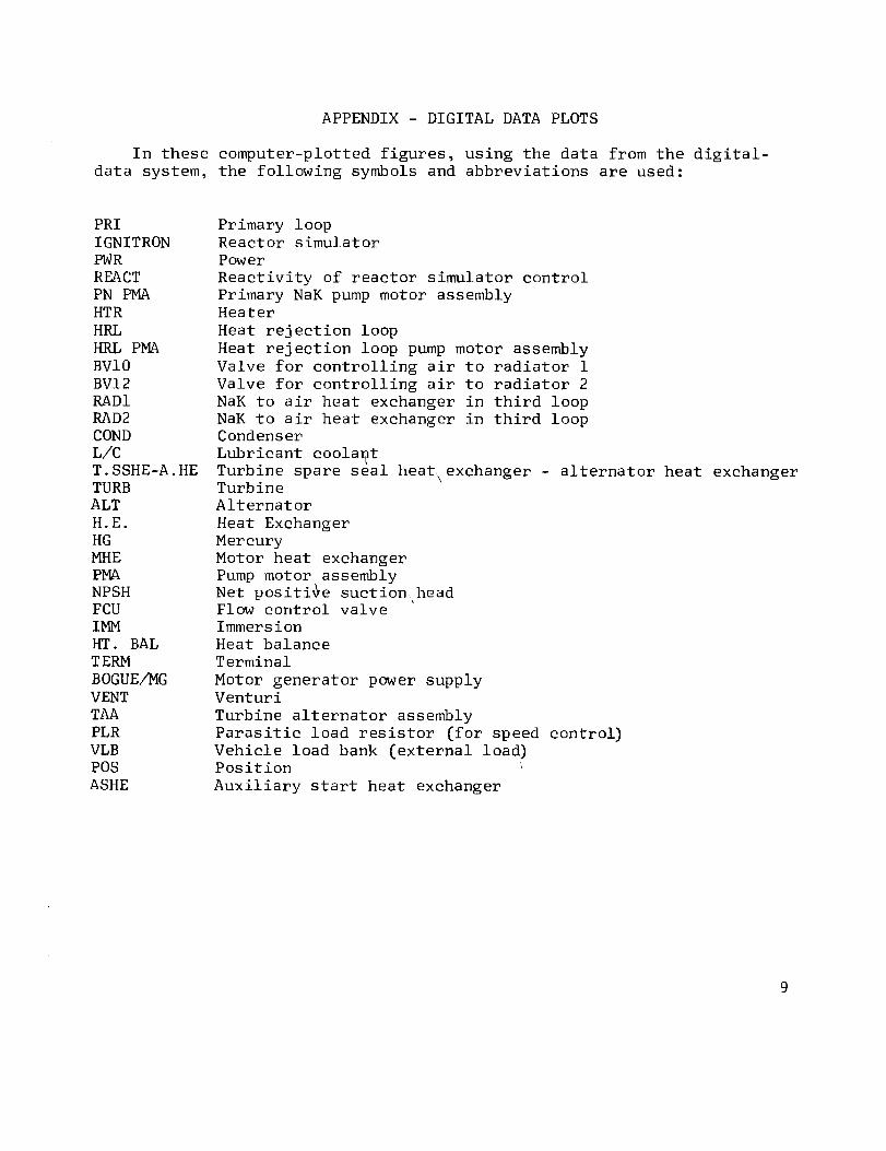
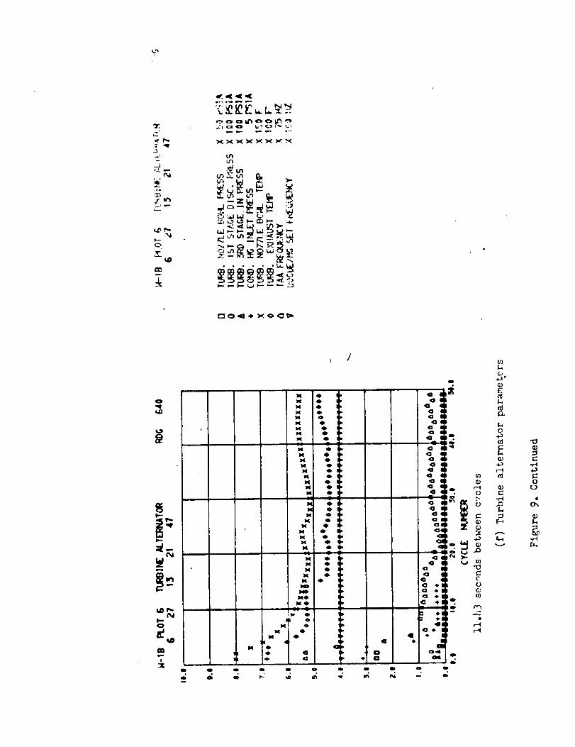
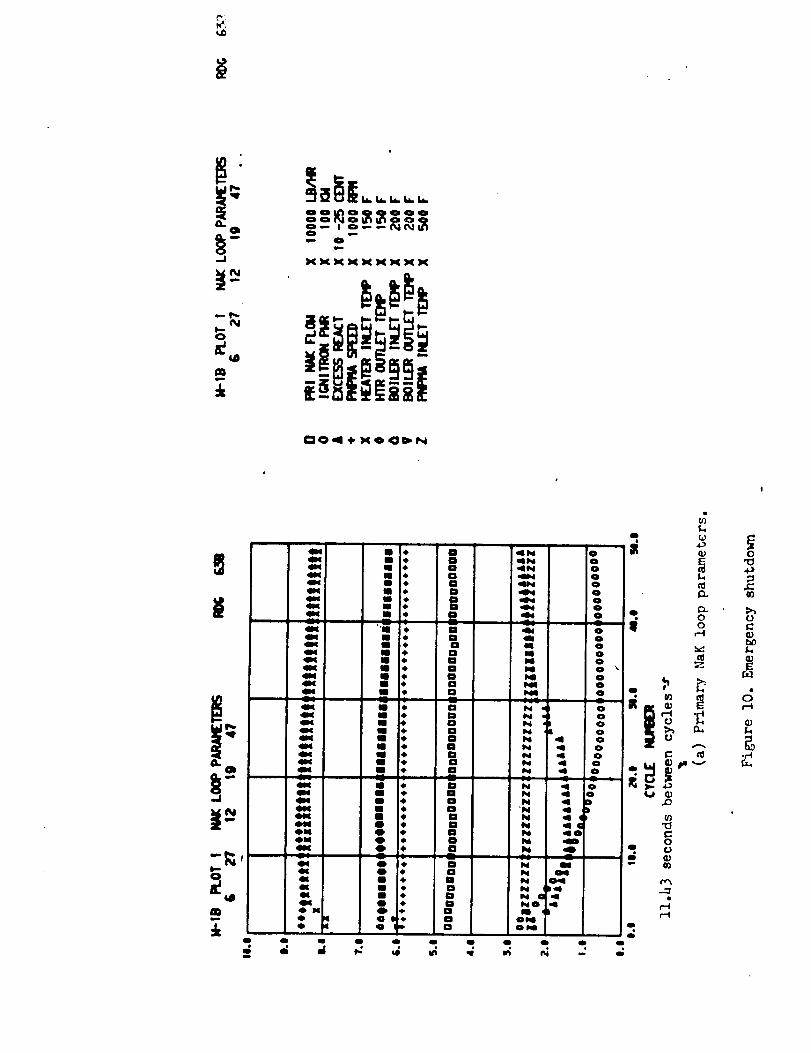
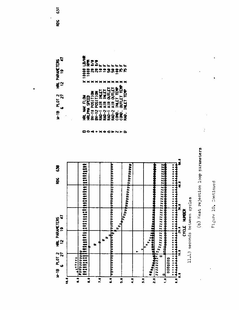
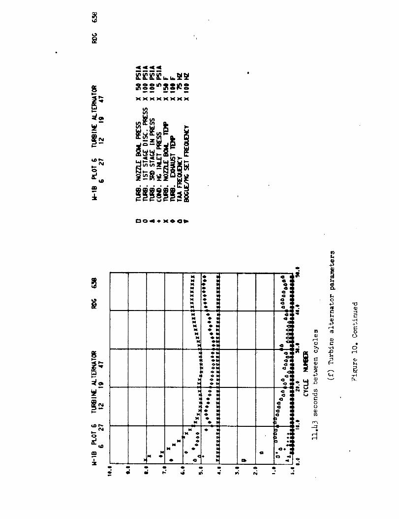
APPENDIX- DIGITAL DATA PLOTS
In these computer-plotted figures, using the data from the digital-
data system, the following symbols and abbreviations are used:
PRI
IGNITRON
PWR
REACT
PN PMA
HTR
HRL
HRL PMA
BVI0
BVI2
RADI
RAD2
COND
L/C
T. SSHE-A. HE
TURB
ALT
H.E.
HG
MHE
PMA
NPSH
FCU
IMM
HT. BAL
T ERM
BOGUE/MG
VENT
TAA
PLR
VLB
POS
ASHE
Primary loopReactor simulator
Power
Reactivity of reactor simulator control
Primary NaK pump motor assembly
Heater
Heat rejection loop
Heat rejection loop pump motor assembly
Valve for controlling air to radiator 1
Valve for controlling air to radiator 2
NaK to air heat exchanger in third loop
NaK to air heat exchanger in third loopCondenser
Lubricant coolant
Turbine spare seal heat\exchanger - alternator heat exchangerTurbine
Alternator
Heat Exchanger
Mercury
Motor heat exchanger
Pump motor assembly
Net positive suction head
Flow control valve
Immersion
Heat balance
Terminal
Motor generator power supplyVenturi
Turbine alternator assembly
Parasitic load resistor (for speed control)
Vehicle load bank (external load)
Position
Auxiliary start heat exchanger

0
-I
P
elSdeJnsSeJd
I¢:
,::3J_
¢11
E0Z
i
P
I..i.
...... i
....... i
• , , o
.-i- ..... i
..... i
h• " " I
.... i
:+--....... i
'-+-_- "3
......... i ::1
r--t .......... I
...... i
N
l Lllql+_01-I
ZH_3uenl_Jj
• + + • . .....
. . ++ ..... ,
-++.. - _.. • + .
_.. _.-+ .....
s_e_oiPl
! E
0
!
-I
$

,oq_l
i
]i i J• ! ]
-g_.2.'-.• l" , Iz
_-.,A ....
tlSd_JnSS_d
iq_ll
Pw
, Ii
r - •
t ;
• _i
"° _I-T_ "" '
....... :2._ _ ,.
• ..4,._, .
!I 1
_ _ v -7,
(Tgd) a.n_sa_td paou_Ivqun
!
0coo4
o4
0
o_
00_04
8t_
0cOr-4
r-I
o
L_
A
Q)
.r..I0 _
_ C
_ 4
c:r,_
o _
m _ ci1)
•_ (J 0
0
t,l
C0
I
g

L
t
........... 0
....... " a
....... I
• • - *- O
.......... B
_r
J_mU,
:Io_n#u_Z
f
!
A
PkximLa Allo_mble
rate of change ofteupermture duringtransient _ F/rain)
6oo
5OO
3O0
200
0
o- ---4.-- •
\
o _o 20 lO 4o $O _o 70 I_
Duration o1' transient (Nconds)
e(m
Figure ). - Allowa_le transient characteristics vs. trmmsient d_rmtlenfor the $UPb8 reactero

C
I,,i-
i,.,n
i#iI
m
I:: I: i: .... I i:l I _ ...........
. , , .... !| , , L _I I I ! .I.. t i • L . I , . L I i , . ' ,,j " I " .......i " ' l
I-. _ i ' t' ' ' : ; , _ : , i I _ I I 1 ] " '.. t-_1 'I' _ i'' ,' _......_ I ,Iz,_ ' '
(a) Mercury liquid flow.
. I I ; _; _ - . i _ , ' , _ J.--'_: i i : : : : ' . ..... "
]_ ' ' i ,/.._+.! .... : ....... i
! i _''_.,.till '':; ........... l.soo i _ LI " ' ' _ " : " : ' " '! _; ; .... " ........... : _t , , _ , ! l _ _ _ / I i '
(b) Turbine-alternator frequency.
: ., ! ............. ::I ! : :t, _ , : , ' ........... . : :..1,_ , , . : ! ........... . I . • /I. ;,. I _ ..... _ _ ...... . .... J .._|
._:.... !: :'. : ...... ,;...: ..... :_;............... ,-,I50(' l . ,
(c) Boiler inlet pressure.
o,, • , , , ,,. ;j.__.,__;-_ ........ :.i ;.:jt_ .... I ....... ; _ .... i, ................ t'-tt ....- !'-....... ! " L ,.i ;; ................... 11r;-_--,I!...... : ' /:: :::: : i-:;-'::: ........ ,-" ]
_---':i::: : ::::::.J'.:::: ............ " ....... :_:: :1- :_-t:::-I_"I .... ;_ - . ..... _ .... I ............ _ /
_'-_ " " . t ' " : _ ._ .... ; ; - - • - ...........
2ooL] / / ' I , , _ ' ; , '
(d) Boiler outlet pressure.
l--_ , i , i • " " " • I ' " +' : : : : : : ........ 'l IL-_. I.. : , , " "* .... " '" ' ' .... 1 ""
I :I - :' 'T' : " ' ": : .... "" : : : : ] " : : : : ..... '" "t" I,
_1-;'1'.. : _: ' --, " ' '(e) Alternator power.
O I I, "i ............. , .... t. ..tt ......... ;,;,.l ...... -';'_1' ............. ,.... • ! • . . . _ : : ..... t ......... :
. .......... . . :. : _ .... _ _
i .... . i [ , • ',_: '_0 ,_0 I_ ZlO
_o Time, sec
: :,,ioIEnd of test
(f) Parasitic load power.
Figure 4. - Emergency shutdown test-
Z-
201]
(k) Heat rejection loop NaK flow.
,:, l!!l_iill, ,ll.;I-i_LII...._i::1i_: .: :::: _Itl_'2"2QIi[:lll::till ::::Ii• . ,: ..... ;l_',,. ,. _ ,._-"---_q-P_k_l;. ., " I
I+ ........ ' I i t _+ , I + i , _ +-tl I ' - - i _ • ..... I
Time, sec End of test
(I) Standpipe inventory.
Figure 4. - Continued.
t I
(Igd) a_ns6oad poou_I_qu_
?0
¢J
¢0
F_
u_
_o
C C
C co
o _ ._
gr-c_ .r_
0Cr
r..-t m
•et o o
tm _ _
o'_ _
bl
.,-t
C0¢D
I
g._

e-
g
O..B
-i
I_.o
-s L
!--
OlI
12,5001
of
• It ' t " _ " _ _' I "• 4 : i . . : o t ; i
I _ I, _ • , * • 1 t ,
I ,l_ r,_!- i
: • ' l ; ; i ! !
(nl Mercury liquid flow.
............ , l ' ' I |....... _! _ _ P i ...... I
i..... / ........ ;i ..... ,.,;.., I.-
-r
Io) Tu rbine-alternator frequency.
I--7I- ........... ' :-.. !'' _:____-:-_-i-_7,-Ii- - , ; , • i : .... : ; : ; I_'--+---_-T -" ' ' "t'' _ ' ,gin-. --1i ................. ._ .... __+___ _, . ÷ .... _-4-.-.. _-_-..Li- --
12,5oo !I_l ....
"_N
I,.I.
PIll
,G,="_.ll,.
,,.lie '
m
• [;;;11'I[4 ;r'
i < , I _
i _ ' I _
l_li_ i, _ ]"t_ q • i
(a) Mercury liquid flow.
°lit i. i if: ;i', t I/fl I ! _11: :::!;i::; _
t 1 ....
t i _ • Ii ..... i'I ....
I 1 ' ,II ' ' ii
! iiiii,,l; i
(b) Turbine-alternator frequency.
Oi ' i ] " l ] I I l I_ , I J ' 1 ; i " 1
JIt1+-.--t ,._ _. -' ............... i i ,I. + .Ill .... t ' +-,-4 .--i i .......... ; . ; 4 l' tI il, t I i I i ......................... i i . ; , , ;I _Jt-i I t_ , t---t ....... : • . . : ....... I , , .... ;
(c) Boiler inlet pressure,
OI '., _._ i I ! : I , , .... i .... I T.......... |
iv" .... I1 _ . i ' 'I!t _' i ''_ ...... i' : ,
• "'_ _ i ;* ...... Ii •..... -l_ t * ........
. _ .._-__ T_I............... '.7 I
200'-_J""' _ . i , . i , t ,
(d)Boileroutletpressure.
°1--i7,-4-i _ t... ;i.,. ............. ,
I-.#-tt--,--t---_-_--,.... f ............. i • i
IL.:_-r.S.Z_. ........ : • . 't
_.-, .,.;.......... ,...... : :_ii _ . ' ' I -: T "-L-1 " "
II
(e) Alternator power.
i I ' '....... | . >
...... i ..... Fi• I
• . i.
II
: !i' i: ......
!tiiiI il _!1 .
: i! :j I_i i i i i.. I l
...,o_ i i ,_ _o_ i_7Time, sec
(f) Parasitic load power.
End of test
Figure 5. - Emergency shutdown test-

C
__,+.Ni,.i,.
0. I
,', l
I,,.,-
_,.,=,.m _ i
i titi IillI'Lt',, i! _ ........ t .... _ I ,,
(g) Mercury liquid flow.
I;:F.:i,l,_: .... :, ' i i ::ii:+iiii.: ' : ' :: ' ; " : " I i, It., ' : I ' : ......
!': , ,,:(hi Turbine-alternator frequency.
0 .... • ' 'l '
: _:'!L2""-"-'+_'"-' ..... ' ........ "-+-+ I -IL, :t:'.:'. .,,<..i ... _- . ; ....... +-.... ++. _ • '
_ /. -+, ' '' _ _ ........... t_' ]{ t:rt [ '
•+.................. r ! :}_II......._ !i':I?_!::-::-:.:--::-::-:!:t t- i._ .I _:"-"...... : ,- ++-
(i) Condenser inlet pressure.
0 '.. .1....;: ..... :: . r.I, ii.... ; ....... + ' + t ' *+ + +
f+- .... t-+--+.-++.......... t ":tl t50 I ' " "
(j) Condenseroutlet pressure.
o ::..1 ..:: ......... : .... "-:-t-' i t-;tf .... , ........ t_....... t__t+i.,tit+t-, _t.... _ _ " t ............. t _+..I " .... I+
F...... ,L ......... ,; _+...... l: ; : : : ' " : + + l : : _ ......... + l + +
+ .... I ................... " .... t ++ -+
(kl Heat rejection loopNaKflow.
oi.: , .... ;_I,+ ..... ' .... 'l-;-+ :+-[ :--'t+_-+_,t +4t_' ""' ..... + ...... 1,/ ;,,
_: i,i: i_,+,tl:,lltti..It.[l,;llllil
I_,++'.++J-i!:i'+ .......;.: ...... ' " l ' :_lt.+.._lli.. : .... .: ,, ,,
Timi. sec
[:l_ I ..
t+! i-i!'+_- i' :i: ¸ ti,..
+-i+]:+t .... +I
-_+t- ++t " '- .... ++-1-+-'+"--1
L.I.-.._.!,i : i ;i+ I
dso " z'm : z_
EndofTest
(I) Standpipeinventory.
Figure5. l Continued.
0
(!sd) eansge,zd peou_l_qufl
¢-4I
8r-4
0oO
0,,0
0.=
0o,J
o
¢.)
to
r,..,
c. ¢D
•_ ,=-
-,-40 CL
C C
C
m __ r-_ _0 _ ..c:
_ I1) .-t0.,_ _.
,-4 m
m _ c"
•_ _ 0
_ .elu_ e
4
C.,-_+)r"0
£b
I
g.H
._._

C:
i_ _el
I.I. J=l
3
E
,,-,i
m
8.°E
:;I; ¸ !! ! ....'i;; ;ii ' _;ii i.'' I _ .... : _ ._i_iil
(n) Mercury liquid flow.
_ t ' i i [ .... Ii :i
(o)Turbine-alternatorfrequency.
i!IIIIiIi!]!i[Ii !lii[
,i! _ _
0 . r • " :
50,000' .....
0 * / "; ' •
" _ " " ' ...... t ÷, • _ °'° ' _ t__ - ° 4- _ 1 • . /I , 'li 111tl i * [ I L T
....... '.-.. _"-T_,. L_ : ..._- .... _!- -i._-.t- .........
=_,_.,....,L.,.., _ i I _; _. _ t; _ . . _. ....... -4 .... t...... __
....... ! J ' ' ' t l-f I I J ! .......... "........... _'---r-"- Testcoefficients
(p) Reactorsimulatorpower.
..... I
Iq) Primary loop NaK flow.
lie0 ........ _ : , - _ , ._ _ _ - .
....... • ...... _ _ _- ................... -4---_ - r r - - _"
• - I i ........ _ , I i , . , ; I _ ...... _........ ' .... ;-- '. _ 1-4 ;-i _ ._--II_O_ " J ; . Z . = J , I ! .; 1 . . . • " 'l I ' ' ; J J J l J J '! 1
(r) Reactorsimulatorinlet temperature.1200 .... _--_-- •
Time, sec Endoftest
(s) Reactorsimulatoroutlettemperature.
Figure 5. - Concluded.
o
l--0
mp
• -- 0
XKKKXXMXX
DO4÷KO_N
O M 41D
dl_ _' 421_ 4, a
t
t
Ip t
o
o

n,++
_ KxK

qOD'qt
t--
gLI"-
.J
IW'1 'qf
t--C)
!2[
XX_X_X_X_XX
_d _0
0 _ 4 o
p • _3 _o
• a_Q I Q I
P
o. o. o. o 0. o _,
r_
or_
.r4

I,.-O
1,0
|_ o_0
ooooo_o0_00_
XXX_
L/'I_/I
i-'l.- _°
I
_0
4,
L
ql tl ii cl ill Ill 0 I_ Q o O• ° ° , . ° * ....
-H
0

t_ID
,9
4
4
II
II
II
I
II
I
I
_4
-H
0
,S(o
*r-t

o
+i!+°°XXX
_Z_
Z_ZZ
DQ_÷XO_
u?
it-,,
0
OIW13. "ql'
X0-J
,qtf_dr.__,-
0
!Z
0
o oo0o
o
XXXX
J
_ks.,,_rr
_04+XO
f_
h
0P_
C
4
¢1:¢k
• 0
-r_l4_C"0
¢)

C_tY
,m., Ob _.)< )< X X
o _;

' o_o __oO00QOQO
t__ - x_xxx_x
_" > ._
F--'
00
.,-I,--t-f-t
0
,,jr.f-,
.rt

3
r:.'.
..J XXXXXXXXM
0
l/
t:0
*+ i
,Ioqa
" ° _ "V.
I_ _ o N • 12 .,o
o
bl,_O 0 4 IIII. _I 0
'-'he ,m,,
• . o • • • i • . • •
.r-I
0
g.r-I
+!++_ !++
X_XXX_XXX_
n-
a _o
o
!
Do_+xo_
o
N q
) 4>_1
|
oO - _ _. 481 N
o
L0
n_
o Q• °
o O
a 0 4 * N
4 O * N @o4 _ • N a o
o
o _ o m o Q_ _ o
.,-4_3
ou
rio

__I°°°°XXMX_X_
XX
!! I 0 iiLO
!
n_
*r--t
0
r.D
mNmm
_ xxx_xxxxW
qr_
f
DO_÷XO_
t,-,
"_ ! " !
N
q N •
..-" :_..- _
_ _ o _. ° .,
oO qum o O o i_ qmm_ quip o _nm o
• ° , , . • l . . •
-r4
0
rv
°o0
X
X0--I
t--0
!X
Q
0000
XX_X
_09_XO
.r4
r-'-
o
o
o
0
0
.r_
0_D
Q)%
g°_

C_
0
__J
Z'
0C)
;2

o
Q
N
O
t_
_ oQ'ooo
_ xxxxKxxxxx
(0
o • N 14
t o qj,,, N I,,al
r-. 0 g_ N I.I
0 N qll _ • , ,,.-,
_ _ 0 N I r_
)4C_mO_
_ 0
:_ _ o+ , 0 • • , ,
o No No N
O N ,_O NO NQ,,O N W::_,
O _I_.O _I_
:]10 ,,_
:]I-_xm,_
W_ f_
c
_I"_ .__-_
_-_I3 r'i
r_I-i
,- a.
-r-I.D
0C_
n:
_t.D XX 11_XXXXXX
t0
l, O
a.LO
q,,,j _-,.J
0
LO
I
o
o
@ 9@ ¢@ 9@ ,i@ i
° :@@ 4
• ,MI
,11
,II
• 44¢, ,11
44, _1,
• 4
h 44
4 4
4
4
•* .4 -,q I:_
• ° •
O ¢ _ 0OlD (_oO¢ NN 001_ _O
O • _N 00 _ _OO_O NN 00_ I_OO • _N '10 _ _O
nb NN ¢_o 10_
D q O I_
U,_ N O U_ IXlID: N Q I_
lUl_l N O I1,, U0) N O Ilnl, O
N _ _
0¢
0O
oo111 I,,I I_o_ I,,i iii, ¢_13+
o al
i_, i%1
o
II)S.-+
OJ
0
+,+-4
00
m 4-)
.+.-.
._ t,.,,9
5 "-"o _
I.)Q)
ii
T-t¢---t
lID0
oo
o
C0
ll)
/
ooooo_o0_00_
_ -
_ xxxxx_x
O0_÷XO_
(D
c_er
_ °:°°_°°°o
0
tNI
DOq+ KO_N_

_r
0
_ xxxx_xx
,,,*°,
It
DO4+XO_
o'J
• ©
0 I q:
_ -__ _ :_ -_
r_4
° I|
_' t2
_ ° _ o_=) o ,0 _
_ d
• ° . , .......
0F._)

o
_ X_XX
°_Oq÷MO
• \
L.
O0
o_o _
: _ I °
o oo _o i'5
• o D v
d
_! °° o004
4
o
,am 0 m• 3 4
i-4
$ 0 4 $
• 0 q
X o
• • • • • , , , ° ,
0

_t
NmO
_° _o_oo
_ xx x_xxx
m
o _
o_
E
c_
0o
rM
rM
0
t-O
_d
.el

XX_XXX_
QO4+XO_N
III • I_ o a3
g .e D oOI + D
o _um * 0 o
I • D og • C:3 o _.j
I ,e 0
I ÷ Q o
ill • Q
o . o o g _ID + C_ o+ _'_ o
= . ° g _ g
_ _ 0 | _
• • , , * . * ....
V
0,._
_.i
(j,
°_-:
G.
1'%1i,_
I--O
,,t'¢.0
i
oI_I,_I._I,._.I_I,,+.I,+,.
OOOOI
_XXXXK_XXXX
U)
(lJ
ONON = iI" IqI 4,,I
I_bl N 3 • - tO0
ON
: C_I I,q :1 .-r_II N 1 +,
= _ ,I h "m $"iQi ll N 3 $"
0 I_ II I",,I 's ""
I_ II N 'I ¢"" r'_ h
"++'+'I+ N 3 +"
V)
ira.
_ ,_ . °+ ,.,,. .,.....
• _ *+" "i 11,4 3 e._,,I< • +" +.
_ m.. ,¢i_ O I,,,l I'm +
I,,-- _"I"" _ O 41)N _ 4'0 1,, 4, ON 0 I,N I_ 4..
1-31 ,ON 0 • N C3 .I_• I) :,.:m 4m,c O 41, N CI *
]m <IN 0 I N C3 _,,
4M191 Ik +N 0 I N _ 4k._ _1( 0 I N C _'"
91
I +IIl I I I I O I Ill O O• • • • • • • , • • •
--"I
r-(i'-4
C
.OO
Of..+

0
*.3
+i+++x_ xxxxxx_x
(0

o
0 _
i_ _XX_X_X
QO4÷NO_
t

o
,'v
I,..,I tM....I
Oel,,,
U"I I",,.IM
t-O
4,0
el-,
:E
I,b I..- Ij,. t,,,. I,,,.
-°°_X_XX_XX
-
OO
ii t,. _1_ (1)
.,, ,,.
.,_0. ._NF,, D-
l.,,,ll-.e.
NI_I
2 '= "*"
Q.. ,11 _ $1 i. ,il N,W _
_a
cr'li") Q " : _."_ _-I _ O
90 I,I 4. _ _ll ll_ £:1 c,41_ _ .i, I,. ,4 _NcI _)
I-.. 411 _i< 4. ,ill I1,, _ •(:_ ,I1_ .i, '9 ll,, Nil v'--I
_1 ql_ _. .q I,,, Nil r-"l
_ O ,*. 4111: O li.
•T o_11 o o ii el, II, _1_ ,o o cl_ o
• o , , . , . . . . .
"0
E.H
00
r_
_J
C0

O
0 0000
x xx_
x_
i•N
i-o
_n
004_0
n_
-,-I.,0
0
Q)%
.,-4

3
mNQ
iiIIm, • • • • • • •
DO4+XO_
0

__o -
XXXXKXMX_XX
mm_l
rn
f_
Q)E
_)_0o
rl
-1-1r-I-r'4
"0
0
o
o_
g)
C
S-,
dr-_
f-,
4ml • [bem D I_ee4 D
q$m[ O m.
m O r.._'( O r..
m :) I_m :) m.m =) I_ON _
ox _
ox D b
,o_ _
_d
_D
& _; _; ,: ,*" v; 4
Q
i NI .I..INI 4.I NI 4...I) INI .) •Ill P_III 4 ._I) 1.41 .)g
!! _! "" *" Q
II 1"41 '_I NI e*I INI 4,_II N 'l,'11 IN '_"II IN .i,=II I_I ',I*-II N ,)_
I N _,,M q •
M N 0_
N
X_ N
qN
N
III N C 4'" m_,
"" "[3 _,,, r'-t
I_ 4,.
o N C *,_.q_
P4 p ii
0)
c)
It)
Ip
r_00r-_
C0
_,_
q)-r--_
¢0
4,,, I_4.11 12)
c_C_D
d,--t

DO4+XO_N_O
0{3
r_
.rt

G.N
ql' I'_.
O
qd)
4,
0_00
XXX_XNX
r_f_
0
o t
33333
33]3
3,j3|
3]33|3
3!
dt t
4
q4
,4,4
,4
4
,4
q
,9
,el tQ
ii
Q •
Q •O _Q •o IQ _
° ;Q
OI
C_,
O¢'
o ÷
o ÷
o ¢.o
o
° ;OO IooO
o
0
I t Q
¢44
4
NNNNNNN
4.N "_
4. M )4. NC_t4' )4
N O
t
¢¢
Q
OI
I
C_O l-_ "CI
r_
o 4-)
• _(_),ID
, _
00

_KXXXX_
JN0
N
U_I_N
0
_D
n_
=km_
0
&a-'I
f_
tJ
_NmN
W
I
DO4_XO_
.H
0
F_
-,,4

_Oq+KO
o
I::0
c_r-t

DO4÷XO_
_NNt O41
Oql
o4o4
o4
O4
_O_ 4. C X
_1 4. 3 )4C N
4_ 3 M
C 144. C )4
4, K )4
4_ D )qO _ D x
O x
a3 • a C_N4_ CD • an
I 4. O •"I
o o o o o o ? o o
eo_J• ._
oq 0'q 0
q _
,qgl
-- d r,__ .-..-t
a _'_ r-I
oQ
,4I o
_ o
_ o
.0
0
d,'-4
.r.t
! !!!!+++,::++++**oMX X_
00
._
. _ oo _i
" o° _ o: _ oo