carrier ethernet last update 2013.03.13 1.9.1 copyright 2000-2012 kenneth m. chipps ph.d. 1
TRANSCRIPT

Carrier Ethernet
Last Update 2013.03.131.9.1
Copyright 2000-2012 Kenneth M. Chipps Ph.D. www.chipps.com
1
Objectives of This Section
• Learn– What Ethernet is in terms of its use in a CAN,
MAN, or WAN
Copyright 2000-2012 Kenneth M. Chipps Ph.D. www.chipps.com
2
Context
• It depends• If we are talking about the new style
networks where dark fiber is used• Then it is
Copyright 2000-2012 Kenneth M. Chipps Ph.D. www.chipps.com
3
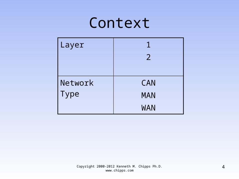
ContextLayer 1
2
Network Type CANMANWAN
Copyright 2000-2012 Kenneth M. Chipps Ph.D. www.chipps.com 4
Context
• But if we are talking about the RBOCs delivering it over existing networks
• Then it is
Copyright 2000-2012 Kenneth M. Chipps Ph.D. www.chipps.com
5
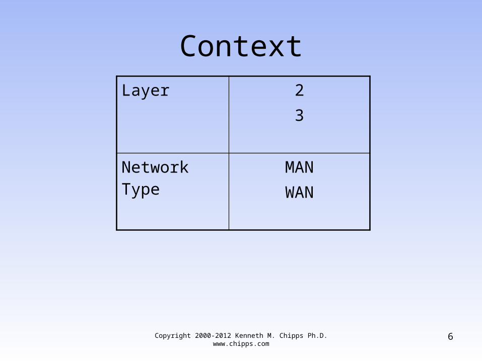
ContextLayer 2
3
Network Type MANWAN
Copyright 2000-2012 Kenneth M. Chipps Ph.D. www.chipps.com 6

Physical Layer Options
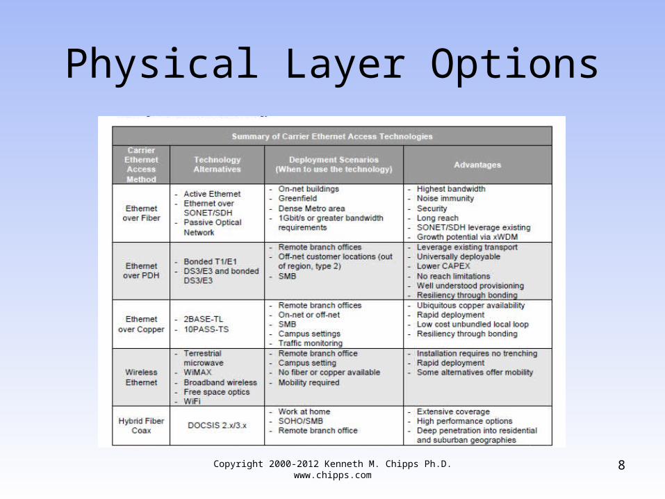
• The MEF – Metro Ethernet Forum defines a number of ways that Ethernet can be delivered at the physical layer to the customers premises
• Here is the summary table they use to illustrate this in a white paper
Copyright 2000-2012 Kenneth M. Chipps Ph.D. www.chipps.com
7
Physical Layer Options
Copyright 2000-2012 Kenneth M. Chipps Ph.D. www.chipps.com
8

What is Ethernet
• Ethernet is the most common network access method used today
• It runs at speeds of 10, 100, 1,000, and 10,000, 40,000, and 100,000 Mbps
• In most cases any or all of these speeds can be run in the same environment
Copyright 2000-2012 Kenneth M. Chipps Ph.D. www.chipps.com
9
What is Ethernet
• Ethernet was first released as a useable IEEE standard in 1983
• It has been updated up through 1999• It will probably continue on indefinitely
Copyright 2000-2012 Kenneth M. Chipps Ph.D. www.chipps.com
10

New or Old
• The difference mentioned above in the context slides is whether Ethernet will be delivered as a whole new network type
• or• As a service just like Frame Relay at layer
2 over the existing SONET at layer 1 and ATM at layer 2 networks already in place
Copyright 2000-2012 Kenneth M. Chipps Ph.D. www.chipps.com
11

Why Use Ethernet
• The reason for all of the interest in all of this is the ease for the customer in connecting to such a network
• Right now we have a break in transportation
• In that a 100 Mbps Ethernet based LAN must be changed to a 1.5 Mbps or less Frame Relay or T Carrier or something else circuit at one end
Copyright 2000-2012 Kenneth M. Chipps Ph.D. www.chipps.com
12
Why Use Ethernet
• Then all of this must be changed back again at the other end
• This requires things unfamiliar to the LAN manager
• Such as– Service Providers– Demarcs– CSU/DSUs– Routers
Copyright 2000-2012 Kenneth M. Chipps Ph.D. www.chipps.com
13

Why Use Ethernet
– Routing Protocols– And so on
• Wouldn’t it be easier if the LAN manager could just plug one end of a plain old UTP cable into a 100 Mbps port in the existing Ethernet switch and the other end into a RJ 45 port in the wall
• With the result being instant 100 Mbps communication with the Internet or one of their other sites
Copyright 2000-2012 Kenneth M. Chipps Ph.D. www.chipps.com
14

Why Use Ethernet
• Even better is the price which is usually much lower than the 1.5 Mbps connection currently being used
Copyright 2000-2012 Kenneth M. Chipps Ph.D. www.chipps.com
15
Ethernet from Service Provider
• It is becoming more and more common to use Ethernet from a service provider such as an ILEC as the primary point-to-point and multi-point access line
• When purchased from a service provider such as AT&T the service is sold as a MAN access line
Copyright 2000-2012 Kenneth M. Chipps Ph.D. www.chipps.com
16

Ethernet from Service Provider
• Let’s look at the description of this type of service from an AT&T white paper from 2009– Ethernet-based MANs are high-speed
networks confined to a moderately sized area, such as a large metropolis, using Ethernet as the transport protocol
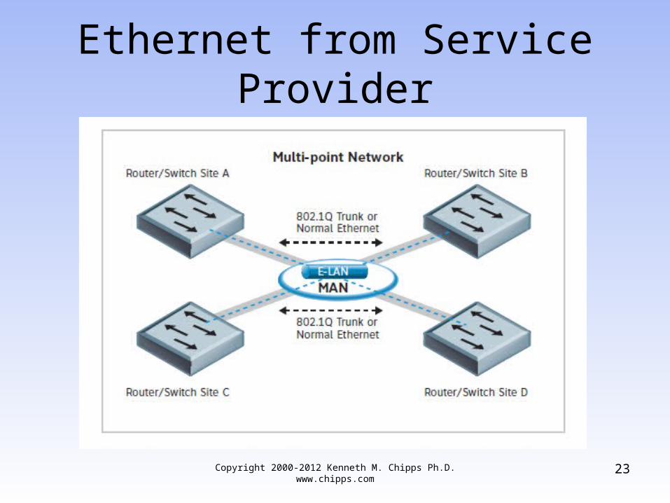
– Ethernet-based MAN networks offer two basic switching architectures
Copyright 2000-2012 Kenneth M. Chipps Ph.D. www.chipps.com
17
Ethernet from Service Provider
• Point-to-point• Multi-point
– A point-to-point MAN connection facilitates communication between two sites, similar to a point-to-point circuit
– Multiple point-to-point connections can be provisioned – multiplexed - to ride a single physical connection using Ethernet 802.1Q VLAN tagging
Copyright 2000-2012 Kenneth M. Chipps Ph.D. www.chipps.com
18
Ethernet from Service Provider
– Each VLAN is mapped to a different point-to-point connection and has a committed information rate (CIR) value
– Multi-point MAN networks offer any-to-any communications among three or more sites, using Ethernet switching
– Ethernet switching will forward multicast, broadcast and some unicast packets to all sites
Copyright 2000-2012 Kenneth M. Chipps Ph.D. www.chipps.com
19

Ethernet from Service Provider
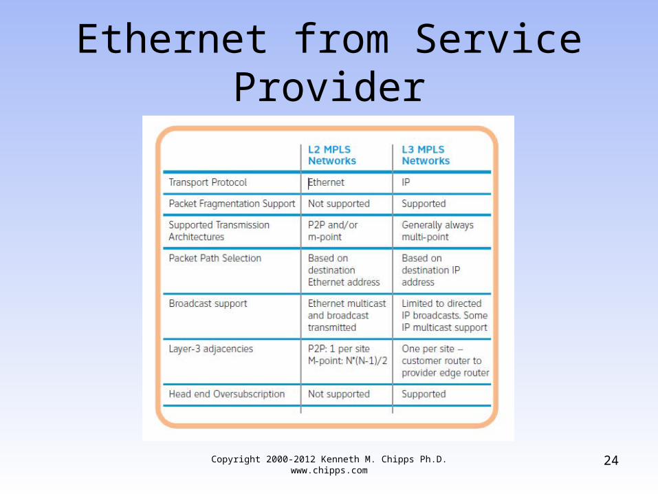
– Important differences exist between layer-2- and layer-3-based networks
– These differences extend into MPLS networks that support both layer-2 switched Ethernet and layer-3 VPN services
– The root of those differences is the protocol used to switch the traffic in the service provider network
Copyright 2000-2012 Kenneth M. Chipps Ph.D. www.chipps.com
20
Ethernet from Service Provider
– Layer-2 MPLS uses Ethernet media access control (MAC) addresses and allows the user to manage routing tables and layer-3 MPLS uses IP addresses and routing is taken care of in the network
– In nearly all cases, a router or layer-3 switch should be used to connect an Ethernet MAN to a customer site
Copyright 2000-2012 Kenneth M. Chipps Ph.D. www.chipps.com
21

Ethernet from Service Provider
Copyright 2000-2012 Kenneth M. Chipps Ph.D. www.chipps.com
22
Ethernet from Service Provider
Copyright 2000-2012 Kenneth M. Chipps Ph.D. www.chipps.com
23
Ethernet from Service Provider
Copyright 2000-2012 Kenneth M. Chipps Ph.D. www.chipps.com
24

Which One to Use
• Juniper in a white paper on carrier Ethernet VPNs states this about the choice between layer 2 and layer 3 VPNs over an Ethernet connection– VPNs are classified as either Layer 2 or Layer
3– In the case of a Layer 2 VPN, the provider
network offers only transport services between the CEs of the VPN
Copyright 2000-2012 Kenneth M. Chipps Ph.D. www.chipps.com
25

Which One to Use
– The routing and peering takes place between CEs; the provider network itself is oblivious to the IP addressing and internal organization of the customer network
– This type of VPN is also known as the overlay model
– Traditional Layer 2 VPNs include Frame Relay, ATM, or time-division multiplexing (TDM) networks
Copyright 2000-2012 Kenneth M. Chipps Ph.D. www.chipps.com
26
Which One to Use
– Modern Layer 2 VPNs use IP/MPLS across the provider network
– In contrast, Layer 3 VPNs have the CEs peering and exchanging routing information with the directly attached PE devices
– The provider network can present each customer (or logical network) with route distribution and transport services
– Such a model is referred to as the peer model
Copyright 2000-2012 Kenneth M. Chipps Ph.D. www.chipps.com
27
Which One to Use
– Selecting between these models depends on the level of service provider involvement in the customer’s network operations
– If the customer’s goal is to use the provider network only for data transport, a Layer 2 model is better suited since the IP addressing and CE maintenance remains the customer’s responsibility
– This is more common for large enterprises
Copyright 2000-2012 Kenneth M. Chipps Ph.D. www.chipps.com
28
Which One to Use
– The Layer 3 model is appropriate if there is a requirement for the network operator to configure and maintain IP addressing for the customer, which is more typical when the customer is a medium-sized business
Copyright 2000-2012 Kenneth M. Chipps Ph.D. www.chipps.com
29
Service Levels
• The SLA for Carrier Ethernet services define three levels or colors of traffic
• As explained in a white paper from the MEF– The user should understand the basic
elements of the Service Level Agreement (SLA)
Copyright 2000-2012 Kenneth M. Chipps Ph.D. www.chipps.com
30

Service Levels
– Users purchase bandwidth, called Committed Information Rate (CIR), from the Service , the CIR is 50 Mbit/s and the physical interface is Gigabit Ethernet
– If the customer inputs data to the network in accordance with these limits, the Service Provider SLA guarantees to deliver the traffic at the CIR meeting certain performance objectives for Frame Delay, Frame Delay Variation, and Frame Loss Ratio
Copyright 2000-2012 Kenneth M. Chipps Ph.D. www.chipps.com
31
Service Levels
• Here is the diagram they use to illustrate this
Copyright 2000-2012 Kenneth M. Chipps Ph.D. www.chipps.com
32

Service Levels
Copyright 2000-2012 Kenneth M. Chipps Ph.D. www.chipps.com
33

Service Levels
• The Service Provider may also offer an Excess Information Rate (EIR) and Excess Burst Size (EBS) in which it agrees to carry the traffic if there are no congestion problems in the network
• Traffic which conforms to the CIR/CBS criteria is called green traffic and treated according to the SLA
Copyright 2000-2012 Kenneth M. Chipps Ph.D. www.chipps.com
34
Service Levels
• Traffic which is above the CIR/CBS rate/size but within the EIR/EBS is labeled as yellow traffic in order that it can be dropped anywhere within the network that congestion is a problem
• Yellow traffic is delivered on a best efforts basis where the SLA parameters are not enforced
Copyright 2000-2012 Kenneth M. Chipps Ph.D. www.chipps.com
35

Service Levels
• Traffic that exceeds the EIR/EBS is called red traffic and may be dropped immediately upon entry into the service provider’s network
Copyright 2000-2012 Kenneth M. Chipps Ph.D. www.chipps.com
36
Carrier Ethernet 2.0
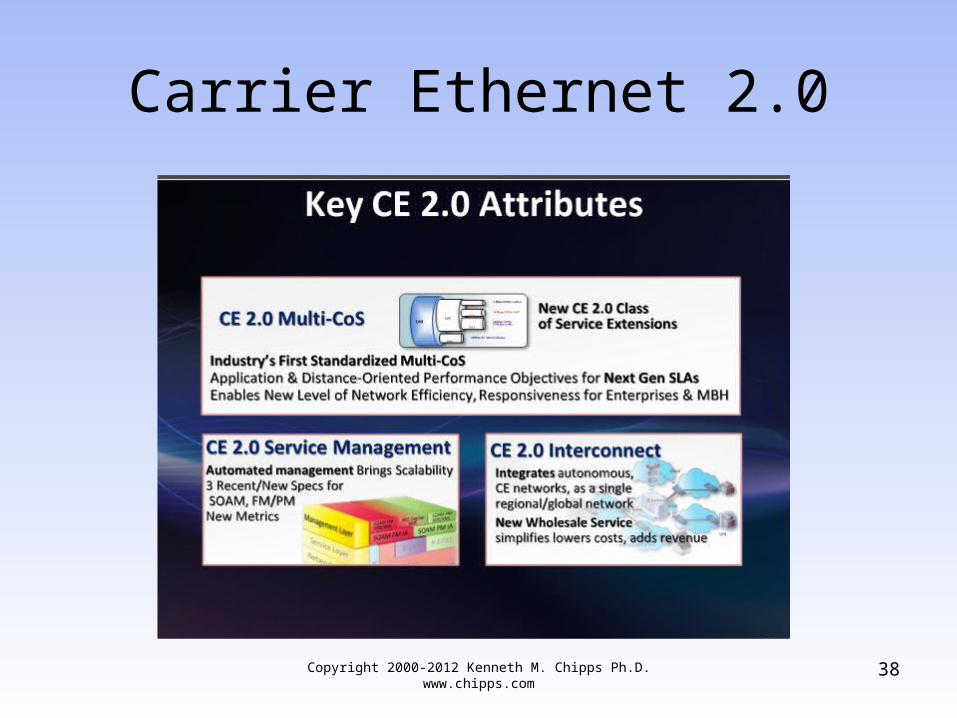
• Carrier Ethernet 2.0 was released in February 2012 it is designed to make interoperability between carriers easier
• Here is some information on this from a webinar by Light Reading in May 2012
Copyright 2000-2012 Kenneth M. Chipps Ph.D. www.chipps.com
37
Carrier Ethernet 2.0
Copyright 2000-2012 Kenneth M. Chipps Ph.D. www.chipps.com
38

Carrier Ethernet 2.0
Copyright 2000-2012 Kenneth M. Chipps Ph.D. www.chipps.com
39

Carrier Ethernet 2.0
Copyright 2000-2012 Kenneth M. Chipps Ph.D. www.chipps.com
40