cardell veterinary vital signs monitors - midmark · 21-02-0186 rev. 09 3/15 1 cardell® veterinary...
TRANSCRIPT

21-02-0186 REV. 09 3/15
1
CARDELL®
Veterinary Vital Signs Monitors
Models 9403, 9404 and 9405
User’s Manual Manufactured for:

21-02-0186 REV. 09 3/15
2

21-02-0186 REV. 09 3/15
3
CARDELL®
Veterinary Vital Signs Monitors
IMPORTANT: This manual addresses all parameters of the CARDELL
Veterinary Vital Signs Monitor. Not all monitors have all the
parameters referred to in this manual.
Read this Manual completely before using this equipment.
WARNING: The CARDELL Monitor is to be operated by qualified
personnel only. Before use, carefully read this manual,
including accessory directions for use, all precautionary
information, and specifications. The user must check that
the equipment functions safely and see that it is in proper
working condition before being used.
CARDELL Veterinary Vital Signs Monitors
Model Number Installed Parameters
9403 NIBP, SpO2, ECG, Temperature
9404 NIBP, ECG, Temperature
9405 NIBP, SpO2, CO2, ECG, Temperature

21-02-0186 REV. 09 3/15
4
In the U.S. the following Caution applies:
CAUTION:
Federal law restricts this device to sale by or on the
order of a veterinarian.
First Printing: 04/2004 Revised: 05/2004 Revised: 09/2004 Revised: 08/2005 Revised: 12/2006 Revised: 07/2007 Revised: Revised:
05/2008 05/2009

21-02-0186 REV. 09 3/15
5

21-02-0186 REV. 09 3/15
6
This page is intentionally left blank

21-02-0186 REV. 09 3/15
7

21-02-0186 REV. 09 3/15
8
This page is intentionally left blank

21-02-0186 REV. 09 3/15
9

21-02-0186 REV. 09 3/15
10
This page is intentionally left blank

21-02-0186 REV. 09 3/15
11
Manufacturers Declaration of Conformity
Electronic Emissions and Immunity
The Model 9403/9404/9405 Monitor is intended for use in the electromagnetic environment specified below. The customer or the user of the Model 9403/9404/9405 Monitor should assure it is used in such an environment.
Emissions Test Compliance Electromagnetic Environment
RF emissions – CISPR 11 Group 1 The Model 9403/9404/9405 Monitor uses RF energy only for its internal function. Therefore, its RF emissions are very low and are not likely to cause any interference in nearby electronic equipment.
RF emissions – CISPR 11 Class B The Model 9403/9404/9405 Monitor is suitable for use in all establishments, including domestic establishments and those directly connected to the public low-voltage power supply network that supplies buildings used for domestic purposes.
Harmonic emissions IEC 61000-3-2
Class B
Voltage fluctuations / flicker emissions
Complies
Immunity Test IEC 60601 Test Level Compliance Level Electromagnetic Environment
Guidance
Electrostatic discharge (ESD) IEC 61000-4-2
+/-6 kV contact +/-8 kV air
+/-6 kV contact +/-8 kV air
Floors should be wood concrete or ceramic tile. If floors are covered with synthetic material, the relative humidity should be at least 30%.
Electrical fast transient/burst IEC 61000-4-4
+/-2 kV for power supply lines +/-1 kV for input/output lines
+/-2 kV for power supply lines +/-1 kV for input/output lines
Mains power quality should be that of a typical commercial or hospital environment.
Surge IEC 61000-4-5
+/-1 kV differential mode +/-2 kV common mode
+/-1 kV differential mode +/-2 kV common mode
Mains power quality should be that of a typical commercial or hospital environment.
Voltage Dips, short interruptions and voltage variations on power supply input lines IEC 61000-4-11
< 5% UT (>95% dip in UT) for 0.5 cycle. 40% UT (60% dip in UT) for 5 cycles. 70% UT (30% dip in UT) for 25 cycles. < 5% UT (> 95% dip in UT) for 5 seconds.
< 5% UT (>95% dip in UT) for 0.5 cycle. 40% UT (60% dip in UT) for 5 cycles. 70% UT (30% dip in UT) for 25 cycles. < 5% UT (> 95% dip in UT) for 5 seconds.
Mains power quality should be that of a typical commercial or hospital environment. If users of the Model 9403/9404/9405 Monitor requires continued operation during power mains interruptions, it is recommended that the Model 9403/9404/9405 Monitor be powered from an uninterruptible power supply or a battery.
Power frequency (50/60 Hz) magnetic field IEC 61000-4-8
3 A/m 3 A/m Power frequency magnetic fields should be at levels characteristic of a typical location in a typical commercial or hospital environment.
NOTE: UT is the A.C. mains voltage prior to application of the test level.

21-02-0186 REV. 09 3/15
12
Guidance and Manufacturer’s Declaration – Electromagnetic Immunity The Model 9403/9404/9405 Monitor is intended for use in the electromagnetic environment specified below. The customer or the user of the Model 9403/9404/9405 Monitor should insure that it is used in such an environment.
Immunity Test IEC 60601 Test Level Compliance
Level
Electromagnetic Environment - Guidance
Conducted RF IEC 61000-4-6 Radiated RF IEC 61000-4-3
3 Vrms 150 kHz to 80 MHz 3 V/m 80 MHz to 2.5 GHz
3 Vrms 3 V/m
Portable and mobile RF communications equipment should be used no closer to any part of the Model 9403/9404/9405 Monitor, including cables, than the recommended separation distance calculated from the equation applicable to the frequency of the transmitter.
Recommended separation distance:
d = 1.2 P
d = 1.2 P 80 MHz to 800 MHz
d = 2.3 P 800 MHz to 2.5 GHz
Where P is the maximum output power rating of the
transmitter in watts according to the transmitter manufacturer and d is the recommended separation
distance in meters. Field strengths from fixed RF transmitters, as determined by an electromagnetic site survey a , should be less than the compliance level in each frequency range. b Interference may occur in the vicinity of equipment marked with the following symbol:
NOTE 1 At 80 MHz and 800 MHz, the higher frequency range applies. NOTE 2 These guidelines may not apply in all situations. Electromagnetic propagation is effected by absorption and reflection from structures, objects and people. a Field strengths from fixed transmitters, such as base stations for radio (cellular / cordless) telephones and land mobile radios, amateur radio, AM and FM radio broadcast and TV broadcast cannot be predicted theoretically with accuracy. To assess the electromagnetic environment due to fixed RF transmitters, an electromagnetic site survey should be considered. If the measured field strength in the location in which the Model 9403/9404/9405 Monitor is used exceeds the applicable RF compliance level above, the Model 9403/9404/9405 Monitor should be observed to verify normal operation. If abnormal performance is observed, additional measures may be necessary, such as re-orienting or relocating the Model 9403/9404/9405 Monitor. b Over the frequency range 150 kHz to 80 MHz, field strengths should be less than 3 V/m.
Recommended Separation Distances Between Portable and Mobile RF Communications Equipment and the
Model 9403/9404/9405 Monitor The Model 9403/9404/9405 Monitor is intended for use in an electromagnetic environment in which radiated RF disturbances are controlled. The customer or the user of the Model 9403/9404/9405 Monitor can help prevent electromagnetic interference by maintaining a minimum distance between portable and mobile RF communications equipment (transmitters) and the Model 9403/9404/9405 Monitor as recommended below, according to the maximum output power of the communications equipment.
Rated maximum output
power of transmitter
(Watts)
Separation distance according to frequency of transmitter (Meters)
150 kHz to 80 MHz
d = 1.2 P
80 MHz to 800 MHz
d = 1.2 P
800 MHz to 2.5 GHz
d = 2.3 P
0.01 0.12 0.12 0.23
0.1 0.38 0.38 0.73
1 1.2 1.2 2.3
10 3.8 3.8 7.3
100 12 12 23 For transmitters operating at a maximum output power not listed above, the recommended separation distance d in meters can be
estimated using the equation applicable to the frequency of the transmitter, where P is the maximum output power rating of the
transmitter in watts according to the transmitter manufacturer. NOTE 1 At 80 MHz and 800 MHz, the separation distance for the higher frequency range applies. NOTE 2 These guidelines may not apply in all situations. Electromagnetic propagation is affected by absorption and reflection from structures, objects and people.

21-02-0186 REV. 09 3/15
13
WARRANTY POLICY
MONITORS CAS Medical Systems, Inc. warrants the monitor, when new, to be free from defects in material and workmanship and to perform in accordance with manufacturer’s specifications for a period of two (2) years from the date of original purchase from CAS or its authorized distributors or agents except as noted below. The same warranty conditions are made for a period of one (1) year with respect to printer and battery and six (6) months on non-disposable accessories and certain components consisting of reusable SpO2 sensors and other accessories provided by CAS as part of the original purchase. CAS warrants blood pressure cuffs and disposable or single-patient-use products for out-of-box failure only. Where the accessory is not a CAS manufactured product, the manufacturer’s own warranty conditions apply. CAS reserves the right to perform warranty service operations in its own factory, at an authorized repair facility, or at the customers’ site. Our obligation under this warranty is limited to repairing or, at our option, replacing any defective parts or our equipment, without charge, if such defects occur in normal service and with prompt notification. Damage to any part through misuse, neglect, or accident, or by affixing any accessories or attachments other than CAS, Nellcor®, Oridion® and YSI manufactured accessories or attachments, is not covered by this warranty.
ACCESSORIES, BATTERIES, CUFFS, AND CERTAIN COMPONENTS In all cases, policy applies from date of purchase from CAS or its authorized distributors or agents. Batteries: (1) Year Chargers: (1) Year (not including power cord: see other accessories). Cuffs (all): Out-of-box failure only. CO2 Accessories: Out-of-box failure only. Lead Wires: Out-of-box failure only. Patient Cable: (6) Months SpO2 Cable and Sensor: (6) Months - Nellcor SpO2 Cable and Sensor Temperature Probe: (6) Months - YSI Temperature Probe. Other Accessories: Out-of-box failure only. Certain Components: (1) Year - Printer mechanism, but not including Thermal Print
Heads. Print Heads: Out-of-box failure only.
THERE ARE NO WARRANTIES, WHICH EXTEND BEYOND THOSE EXPRESSLY DESCRIBED IN THIS AGREEMENT AND THE COMPANY MAKES NO WARRANTIES OF MERCHANTABILITY OR FITNESS FOR A PARTICULAR PURPOSE.

21-02-0186 REV. 09 3/15
14
This page is intentionally left blank
21-02-0186 REV. 09 3/15
15
HOW TO CONTACT US
For Warranty Issues: For Product Usage Information:
CAS Medical Systems, Inc. Midmark 44 East Industrial Road 10008 N. Dale Mabry Hwy, Suite 110
Branford, CT 06405 Tampa, FL 33618 U.S.A. U.S.A.
Phone: Phone:
(800) 227-4414 Toll Free: 800-Midmark (643-6275) (203) 488-6056
Fax: Fax:
(203) 488-9438 (813) 264-6218
E-Mail: E-Mail: [email protected] www.Midmark.com/Pages/Contactus.asp
x
Web: Web: www.casmed.com www.Midmark.com
Copyright 2004 CAS Medical Systems, Inc.
All rights reserved. No part of this manual may be reproduced without the written
permission of CAS Medical Systems, Inc. CAS reserves the right to make changes to this
manual and improvements to the product it describes at any time without notice or
obligation.

21-02-0186 REV. 09 3/15
16
This page is intentionally left blank

CARDELL® Veterinary Monitors
21-02-0186 REV. 09 3/15
17
TABLE OF CONTENTS
1. INTRODUCTION AND INTENDED USE ........................................................ 25 INTRODUCTION ...................................................................................................... 25 INDICATIONS FOR USE .......................................................................................... 25 CONTRAINDICATIONS ........................................................................................... 25 BRIEF DEVICE DESCRIPTION ............................................................................... 25 PATIENT ENVIRONMENT ....................................................................................... 27 DEFINITION OF TERMS .......................................................................................... 28
2. UNPACKING THE MONITOR ........................................................................ 29 INITIAL INSPECTION ............................................................................................... 29 MONITOR CHECKLIST ............................................................................................ 29 OPTIONAL ACCESSORIES .................................................................................... 29
3. SYMBOLS ...................................................................................................... 31
4. SAFETY MEASURES AND WARNINGS ....................................................... 37 AUTOMATIC SAFETY FEATURES ......................................................................... 42
5. ECG AND RESPIRATION MONITORING ..................................................... 45 ECG MONITORING .................................................................................................. 45
POSITIONING ANESTHETIZED PATIENTS ....................................................... 45 POSITIONING CONSCIOUS PATIENTS ............................................................. 45 LEAD ATTACHMENT ............................................................................................ 45 LEAD CONTACT ................................................................................................... 47 RECORDING ......................................................................................................... 48
FREEZE TRACES .................................................................................................... 48 RESPIRATION MONITORING ................................................................................. 49 DETACHING THE LEADWIRES .............................................................................. 51 REMOVING THE PATIENT CABLE ......................................................................... 51
6. BLOOD PRESSURE MONITORING .............................................................. 53 CUFF SELECTION AND APPLICATION ................................................................. 53 SITE SELECTION .................................................................................................... 54 CUFF PLACEMENT FOR A CAT ............................................................................. 54 CUFF PLACEMENT FOR A DOG ............................................................................ 55 LARGER ANIMALS .................................................................................................. 56 CUFF SIZE SELECTION .......................................................................................... 56 NIBP MENU .............................................................................................................. 58 LARGE CUFF / SMALL CUFF OPERATING MODES ............................................. 59 MANUAL MODE FOR BLOOD PRESSURE DETERMINATION ............................ 59 AUTOMATIC CYCLE FOR BLOOD PRESSURE DETERMINATION ..................... 61 STAT MODE ............................................................................................................. 62 BLOOD PRESSURE REFERENCE VALUES ......................................................... 63

CARDELL® Veterinary Monitors
21-02-0186 REV. 09 3/15
18
7. PULSE OXIMETRY MONITORING ................................................................ 65 INSTRUCTIONS FOR USE ...................................................................................... 65
SatSeconds™ ALARM MANAGEMENT ............................................................... 67 SENSOR REMOVAL ................................................................................................ 67 REMOVING THE INTERFACE CABLE ................................................................... 68 PERFORMANCE CONSIDERATIONS .................................................................... 68
8. CAPNOGRAPHY MONITORING ................................................................... 69 ORIDION TECHNOLOGY ........................................................................................ 69
OVERVIEW OF ORIDION MICROSTREAM EtCO2 CONSUMABLES ................ 69 ATTACHING THE INTUBATED CONSUMABLES ............................................... 69 REMOVING THE CONSUMABLE ......................................................................... 73
9. TEMPERATURE MONITORING .................................................................... 75 YELLOW SPRINGS INTERNATIONAL (YSI) TECHNOLOGY................................ 75
10. MONITOR OPERATION ................................................................................ 77 FRONT PANEL ......................................................................................................... 77
DISPLAY AREAS ................................................................................................... 77 MAIN DISPLAY AREA ......................................................................................77 TIME, BATTERY AND NUMERIC STATUS .....................................................78 NUMERIC AND TEMPERATURE ....................................................................79 NIBP NUMERIC AREA .....................................................................................79 EtCO2 NUMERIC SECTION .............................................................................80 PATIENT ALARM MESSAGE WINDOW .........................................................80 EQUIPMENT MESSAGE WINDOW ................................................................80
DISPLAY VISUAL INDICATORS .......................................................................... 80 FRONT PANEL CONTROLS ................................................................................ 82 INFRARED (Ir) DATA PORT ................................................................................. 85
REAR PANEL ........................................................................................................... 86 AC LINE POWER CONNECTOR.......................................................................... 86 FUSE COMPARTMENT ........................................................................................ 86 BATTERY COMPARTMENT ................................................................................. 86 EQUIPOTENTIALITY GROUND POST ................................................................ 86 EXTERNAL DEVICE INTERFACE ........................................................................ 86
LEFT SIDE VIEW ..................................................................................................... 87 CUFF HOSE CONNECTION ................................................................................. 87 TEMP CONNECTOR ............................................................................................. 87 NELLCOR® VET SpO2 SENSOR CONNECTOR ................................................. 87 ECG/RESP CONNECTOR .................................................................................... 88 CO2 SENSOR CONNECTOR................................................................................ 88 CO2 SCAVENGER EXHAUST PORT ................................................................... 88
MONITOR OPERATING INSTRUCTIONS .............................................................. 89 TURNING THE CARDELL MONITOR “ON” ......................................................... 89

CARDELL® Veterinary Monitors
21-02-0186 REV. 09 3/15
19
SETUP MENU .......................................................................................................... 90
ENTERING THE SETUP MENU ........................................................................... 90 EXIT THE SETUP MENU ...................................................................................... 91 SELECTING THE LANGUAGE ............................................................................. 91 AUDIO ALARM SILENCE (SILENCE/RESET Pushbutton) .................................. 91
2 MINUTE AUDIO ALARM SILENCE ...............................................................92 PERMANENT AUDIO ALARM SILENCE .........................................................92
SETTING THE DATE ............................................................................................ 92 SETTING THE TIME ............................................................................................. 93 DAYLIGHT SAVING TIME OPTION...................................................................... 93 SET THE SpO2 PULSE RATE ALARM DELAY .................................................... 94 SELECTING THE TEMPERATURE UNITS.......................................................... 95 TRACE BACKGROUND ........................................................................................ 95
PARAMETERS MENU ............................................................................................. 96 AUDIO/VISUAL MENU ............................................................................................. 99 HISTORY .................................................................................................................. 100
TREND HISTORY ................................................................................................. 102 PRINTING TREND HISTORY ..........................................................................103 ERASING TREND HISTORY ...........................................................................103
ALARM HISTORY .................................................................................................. 104 PRINTING ALARM HISTORY ..........................................................................105 ERASING ALARM HISTORY ...........................................................................105
REAL TIME CLOCK .............................................................................................. 106 PATIENT ALARMS ................................................................................................... 106
CHANGING ALARM LIMITS ................................................................................. 107 ALARM LIMIT VALUES ......................................................................................... 108 SAVING MENU SELECTIONS .............................................................................. 108 RESTORE A PREVIOUSLY SAVED SET OF MENU SELECTIONS .................. 109 RESTORE FACTORY DEFAULTS ....................................................................... 109 AUDIBLE AND VISUAL INDICATORS ................................................................. 110 CLEARING ALARMS ............................................................................................. 111
ECG HEART RATE ALARMS ..........................................................................112 RESPIRATION ALARMS ..................................................................................112 %SpO2 ALARMS ...............................................................................................112 SpO2 PULSE RATE ALARMS ..........................................................................113 EtCO2 ALARMS ................................................................................................113 NIBP PATIENT ALARMS .................................................................................114 EQUIPMENT ALARMS .....................................................................................114
2 MINUTE AUDIO ALARM SILENCE.................................................................... 114 PERMANENT AUDIO ALARM SILENCE .............................................................. 115
BATTERY POWER................................................................................................... 115 BATTERY MESSAGES ......................................................................................... 115 CHECKING BATTERY STATUS ........................................................................... 117
POWER FAIL ............................................................................................................ 117

CARDELL® Veterinary Monitors
21-02-0186 REV. 09 3/15
20
USER MESSAGES ................................................................................................... 118
ECG/RESPIRATION USER MESSAGES ............................................................. 118 SpO2 USER MESSAGES ...................................................................................... 119 CO2 USER MESSAGES ........................................................................................ 120 NIBP USER MESSAGES ...................................................................................... 121
MONITOR MESSAGES ............................................................................................ 122
11. EXTERNAL PRINTER .................................................................................... 129 PRINTER OVERVIEW ............................................................................................. 129
PRINTER CONTROLS AND INDICATORS .......................................................... 130 PRINTER OPERATION ......................................................................................... 131
DIRECT CONNECTION ...................................................................................131 INFRARED CONNECTION ..............................................................................131
CHARGING THE PRINTER BATTERY ................................................................ 133 INSTALLING PAPER ............................................................................................. 134 REPLACING THE BATTERY PACK ..................................................................... 135 INSTALLING A NEW BATTERY PACK ................................................................ 136 PRINTING TO A COMPUTER .............................................................................. 137
12. CLEANING ..................................................................................................... 139 CLEANING OVERVIEW ........................................................................................... 139
THE MONITOR ...................................................................................................... 139 THE DISPLAY ........................................................................................................ 140 PATIENT CABLE AND LEADWIRES ................................................................... 140 CUFFS ................................................................................................................... 140
REUSABLE CUFFS ..........................................................................................140 DISPOSABLE CUFFS ......................................................................................140
PNEUMATIC TUBING ........................................................................................... 141 CO2 CONSUMABLES ............................................................................................ 141 PRINTER ............................................................................................................... 141 SpO2 INTERCONNECT CABLE ............................................................................ 141 SENSOR AND CLIPS ............................................................................................ 141 TEMPERATURE PROBES ................................................................................... 142
13. MAINTENANCE ............................................................................................. 143 MAINTENANCE INTERVALS .................................................................................. 143 SERVICE MENU ....................................................................................................... 144
ENTERING THE SERVICE MENU ....................................................................... 144 EXIT THE SERVICE MENU .................................................................................. 145
IrDA TEST ................................................................................................................. 146 CO2 CALIBRATION CHECK .................................................................................... 146 CO2 CALIBRATION .................................................................................................. 147 NIBP CALIBRATION CHECK ................................................................................... 148
MANOMETER PRESSURE CHECK ..................................................................... 149 OVERPRESSURE ................................................................................................. 150
PNEUMATIC PRESSURE CHECKS........................................................................ 150 PLUG TUBE ........................................................................................................... 150 500 ml PRESSURE CHECK ................................................................................. 151

CARDELL® Veterinary Monitors
21-02-0186 REV. 09 3/15
21
PIC VOLTAGE .......................................................................................................... 152 SOFTWARE VERSIONS .......................................................................................... 152 TEMPERATURE CALIBRATION CHECK................................................................ 153 SpO2 CALIBRATION CHECK ................................................................................... 153 REPLACING THE MONITOR BATTERY ................................................................. 154
REMOVING THE BATTERY ................................................................................. 154 INSTALLING THE BATTERY ................................................................................ 154
CHANGING THE FUSES ......................................................................................... 155 STORAGE ................................................................................................................ 156
14. ACCESSORIES ............................................................................................. 157 BLOOD PRESSURE CUFFS ................................................................................... 157 ECG/RESPIRATION ................................................................................................. 158 OXIMETRY ............................................................................................................... 158 CO2 ............................................................................................................................ 158 TEMPERATURE ....................................................................................................... 158 OTHER ACCESSORIES .......................................................................................... 159 MONITOR CONFIGURATIONS ............................................................................... 159
15. SPECIFICATIONS ......................................................................................... 161
16. APPENDIX ..................................................................................................... 171 DEAD SPACE - Cause, Effect, & Control in Small Animal Anesthesia ................... 171
17. PURCHASING RECORD ............................................................................... 173

CARDELL® Veterinary Monitors
21-02-0186 REV. 09 3/15
22
FIGURES
Figure 1: Patient Environment ................................................................................................ 27
Figure 2: 3-Lead Placement .................................................................................................... 46
Figure 3: 5-Lead Placement .................................................................................................... 47
Figure 4: Detaching the Leadwires ........................................................................................ 51
Figure 5: Removing the Patient Cable ................................................................................... 51
Figure 6: Cat Cuff Placement .................................................................................................. 54
Figure 7: Dog Cuff Placement ................................................................................................ 55
Figure 8: Full Velcro® Engagement ....................................................................................... 56
Figure 9: NIBP Menu ................................................................................................................ 58
Figure 10: Sensor to Interface Cable ..................................................................................... 66
Figure 11: CO2 Connection ..................................................................................................... 70
Figure 12: Attaching the Airway Adapter .............................................................................. 71
Figure 13: Front Panel View .................................................................................................... 77
Figure 14: Main Display Area .................................................................................................. 77
Figure 15: Time, Battery and Numeric Status ....................................................................... 78
Figure 16: Numerics and Temperature .................................................................................. 79
Figure 17: NIBP Numeric Area ................................................................................................ 79
Figure 18: EtCO2 Numeric ....................................................................................................... 80
Figure 19: Front Panel Controls ............................................................................................. 82
Figure 20: Rear Panel View ..................................................................................................... 86
Figure 21: Left Side Panel View ............................................................................................. 87
Figure 22: Turning the Monitor On ......................................................................................... 89
Figure 23: Setup Menu ............................................................................................................ 90
Figure 24: Parameters Menu ................................................................................................... 96
Figure 25: Audio/Visual Menu ................................................................................................. 99
Figure 26: History Menu .......................................................................................................... 102
Figure 27: Alarm History Menu ............................................................................................... 104
Figure 28: Alarm Limits Menu ................................................................................................. 106
Figure 29: Printer Controls and Indicators ........................................................................... 130

CARDELL® Veterinary Monitors
21-02-0186 REV. 09 3/15
23
Figure 30: History Sample Printouts ...................................................................................... 132
Figure 31: Waveform Sample Printouts ................................................................................ 133
Figure 32: Paper Installation ................................................................................................... 134
Figure 33: Opening the Battery Door ..................................................................................... 135
Figure 34: Installing the New Battery .................................................................................... 136
Figure 35: Service Menu .......................................................................................................... 145
Figure 36: Software Versions Menu ....................................................................................... 152
Figure 37: Removing the Monitor Battery Pack .................................................................... 154

CARDELL® Veterinary Monitors
21-02-0186 REV. 09 3/15
24
TABLES
Table 1: Parts of the System .................................................................................................. 27
Table 2: 3-Lead Color and Coding ......................................................................................... 46
Table 3: 5-Lead Color and Coding ......................................................................................... 47
Table 4: Small Animal Cuff Selection .................................................................................... 57
Table 5: Large Animal Cuff Selection .................................................................................... 57
Table 6: Specifications for Intubated Consumables – Airway Adapters ........................... 72
Table 7: Alarm Parameters ..................................................................................................... 107
Table 8: Factory Default Alarm Values .................................................................................. 108
Table 9: Audible and Visual Indicators ................................................................................. 110
Table 10: Monitor Messages .................................................................................................. 122
Table 11: ECG/Respiration Monitor Messages .................................................................... 123
Table 12: NIBP Monitor Messages ......................................................................................... 124
Table 13: SpO2 Monitor Messages ......................................................................................... 126
Table 14: CO2 Monitor Messages ........................................................................................... 127
Table 15: Monitor Configurations .......................................................................................... 159

CARDELL® Veterinary Monitors
21-02-0186 REV. 09 3/15
25
1. INTRODUCTION AND INTENDED USE
INTRODUCTION The CARDELL Monitor is a multi parameter monitor measuring Heart Rate, Respiration, Blood Pressure, Oxygen Saturation, Carbon Dioxide and Temperature. Heart Rate is measured by placing electrodes on either side of the chest that detect electrical changes produced by the heart. The same electrodes for heart rate detection are used to detect respiration through a process called impedance pneumography. Non-invasive blood pressure is measured using the oscillometric technique determining systolic, diastolic and mean arterial pressure. The pulse oximeter function continuously monitors and displays values for functional arterial hemoglobin saturation and a pulse rate. Capnography continuously monitors and displays the concentration of exhaled carbon dioxide (CO2). Temperature is obtained using a temperature thermistor probe that can be applied to sites such as esophageal or rectal.
INDICATIONS FOR USE The CARDELL Monitor is a portable device intended to be used by trained clinicians for multi-parameter vital signs monitoring of veterinary patients. Parameters displayed are heart rate (BPM), respiration (BrPM), non-invasive blood pressure (systolic, diastolic and MAP pressure), end tidal carbon dioxide (EtCO2), respiration rate (RR), functional oxygen saturation of arterial hemoglobin (%SpO2), pulse rate (PR) and temperature.
WARNING: The CARDELL Monitor is intended only as an adjunct in patient assessment. It must be used in conjunction with clinical signs and symptoms.
CONTRAINDICATIONS
No contraindications are known at this time.
BRIEF DEVICE DESCRIPTION The CARDELL Monitor is compact, lightweight and portable, allowing it to be easily carried and used in a variety of clinical settings. The monitor is powered by AC Line Power or by a Nickel Metal Hydride (NiMH) rechargeable battery pack. The internal battery pack charges when the monitor is plugged into the AC wall outlet. The CARDELL Monitor can be set to operate in one of nine (9) different languages: English, German, French, Italian, Spanish, Dutch, Swedish, Portuguese or Norwegian. The monitor’s display window can display various system alarm messages. These messages direct the user to check conditions such as the battery state, air leaks and measurement problems. The monitor’s display window also displays the operational mode of the monitor (Large or Small Cuff).

CARDELL® Veterinary Monitors
21-02-0186 REV. 09 3/15
26
The ECG parameter is intended for three-lead or five-lead ECG monitoring. The Respiration (RESP) parameter is intended to measure changes in electrical impedance caused by chest shape changes associated with inspiration and expiration. The Non-Invasive Blood Pressure (NIBP) parameter automatically inflates an occluding cuff and, using the oscillometric measurement technique, determines systolic and diastolic pressure and mean arterial pressure. Measurement results along with operator prompts and error messages are displayed on the front panel. The frequency of NIBP determination can be selected by the operator in varied times between one and ninety minutes. The auto and manual operating modes cover a variety of clinical uses. The Pulse Oximeter parameter (%SpO2) determines arterial oxyhemoglobin saturation by measuring the absorption of red and infrared light passing through the tissue. Changes in absorption caused by pulsations of blood in the vascular bed are used to determine arterial saturation and pulse rate. The oximeter requires no routine calibration or maintenance. Oxygen saturation and pulse rate numeric values are available for display. When selected as a waveform parameter, a pulsatile waveform is also available for display. When selected on the display as a numeric parameter, on each detected pulse, a bar graph gives the user a pulse-by-pulse visual indication of waveform signal quality. An audio “beep” can be enabled that is generated each time the SpO2 module detects a pulse.
NOTE: The bar graph is not proportional to the pulse volume.
The Capnography parameter is a noninvasive method for continuously measuring the amount of CO2 during every breath, the amount of CO2 present at the end of exhalation (EtCO2) and during inhalation (FiCO2) and the Respiratory Rate (RR). These parameters are useful to assess a patient’s ventilatory status. End Tidal and respiratory rate numeric values are available for display. When selected as a waveform parameter, a CO2 waveform is also available for display. When selected on the display as a numeric parameter, on each exhaled breath, a visual indicator provides a breath-by-breath indication of the patient’s breathing. The Temperature parameter (TEMP) is intended to measure temperature using an attachable probe. The temperature value displayed can be viewed in either Fahrenheit or Celsius.

CARDELL® Veterinary Monitors
21-02-0186 REV. 09 3/15
27
PATIENT ENVIRONMENT The CARDELL Monitor has been tested with specific parts of the “system” used within the Patient Environment. Figure 1, defines the Patient Environment.
Figure 1: Patient Environment
The parts of the CARDELL Monitor “system” that can be used in the Patient Environment are
defined as;
Table 1: Parts of the System
The CARDELL Monitor
Appropriate Accessories, listed in the ACCESSORIES section of this User’s Manual
Line Cord
Citizen CMP-10 Mobile Printer
RS232 Interconnect Cable (supplied with printer)
AC Adapter / Charger, Model TRC-09-1100-M from Group West or equivalent (supplied
with printer)

CARDELL® Veterinary Monitors
21-02-0186 REV. 09 3/15
28
DEFINITION OF TERMS In this manual, “WARNING”, “CAUTION”, “IMPORTANT” and “NOTE” mean the following:
WARNING: Directions that warn of conditions that put the patient or caregiver at risk.
CAUTION: Directions that help you avoid damaging your monitor or losing data.
IMPORTANT: Directions you should be particularly aware of; something not readily apparent.
NOTE: Directions that make it easier to use your monitor.

CARDELL® Veterinary Monitors
21-02-0186 REV. 09 3/15
29
2. UNPACKING THE MONITOR
INITIAL INSPECTION Before unpacking the monitor, inspect the packaging for damage. If there are any signs of damage to the package, a claim should be filed immediately with the shipping agent. It is the receiver's responsibility to notify the carrier's local office to arrange for the pickup of the damaged items. Save the damaged shipping carton as evidence. Contact CAS Medical Systems Inc. to report external damage and to arrange for repair or replacement of damaged equipment. The shipping carton should contain the items listed below. Unpack the monitor and account for each item. Inspect each item for signs of external damage, dents, cracks, scratches, etc. If an item is missing or damaged, contact CAS Medical Systems Inc. Record the monitor model, serial number and date of purchase at the back of this manual.
MONITOR CHECKLIST
Qty Description
1 Monitor (9403 or 9404 or 9405)
1 Hospital Grade AC Power Cord
1 3 or 5 - Lead ECG/Respiration Patient Cable (based on order)
1 3 or 5 - Lead Wire Set (based on order)
1 Six (6) Foot Inflation Hose
13 Midmark Blood Pressure Cuffs, (7 sizes)
1 Nellcor®, Model # DOC-10 SpO2 Interface Cable
1 Nellcor, VetSat® Veterinary SpO2 Sensor and Clips
3 Oridion FilterLine® Sets (for Model 9405)
1 Electrode Gel, 1 Tube
1 P9 Calibration Kit (includes T - connector with tubing and male luer plug)
1 Monitor User’s Manual
NOTE: The monitor is shipped with the appropriate line cord for the country and or voltage being used.
OPTIONAL ACCESSORIES The CARDELL Veterinary Monitor is available with a rolling stand and basket, a soft-sided carrying case, and other optional accessories to fit your needs. Refer to Section 14, ACCESSORIES, for part number information. Contact Midmark for more information.

CARDELL® Veterinary Monitors
21-02-0186 REV. 09 3/15
30
This page is intentionally left blank
CARDELL® Veterinary Monitors
21-02-0186 REV. 09 3/15
31
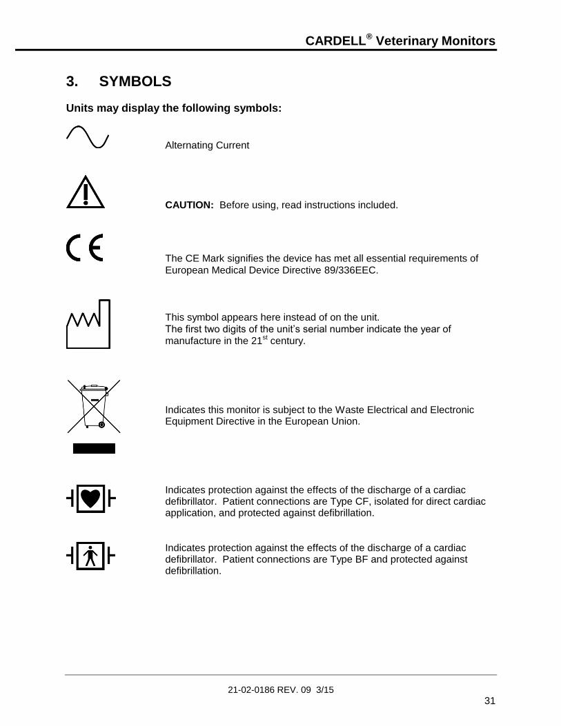
3. SYMBOLS
Units may display the following symbols:
Alternating Current
CAUTION: Before using, read instructions included.
The CE Mark signifies the device has met all essential requirements of
European Medical Device Directive 89/336EEC.
This symbol appears here instead of on the unit.
The first two digits of the unit’s serial number indicate the year of
manufacture in the 21st century.
Indicates this monitor is subject to the Waste Electrical and Electronic
Equipment Directive in the European Union. Indicates protection against the effects of the discharge of a cardiac
defibrillator. Patient connections are Type CF, isolated for direct cardiac application, and protected against defibrillation.
Indicates protection against the effects of the discharge of a cardiac defibrillator. Patient connections are Type BF and protected against defibrillation.

CARDELL® Veterinary Monitors
21-02-0186 REV. 09 3/15
32
SYMBOLS (CONT.)
Equipotentiality Ground Post
IPX1 Protection against ingress of water.
ECG/RESP ECG/Respiration Input Connector
NIBP Hose and Cuff Connector
SpO2 Pulse Oximeter Probe Input Connector
CO2 MicroStream™ CO2 Input Connector
CO2 Scavenger Exhaust Port
TEMP Temperature Probe Input Connector
Two way Communication Port
RS232 Interface Connector
CARDELL® Veterinary Monitors
21-02-0186 REV. 09 3/15
33
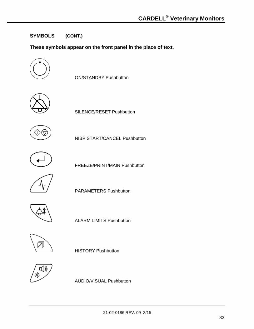
SYMBOLS (CONT.)
These symbols appear on the front panel in the place of text.
ON/STANDBY Pushbutton
SILENCE/RESET Pushbutton
NIBP START/CANCEL Pushbutton
FREEZE/PRINT/MAIN Pushbutton
PARAMETERS Pushbutton
ALARM LIMITS Pushbutton
HISTORY Pushbutton
AUDIO/VISUAL Pushbutton

CARDELL® Veterinary Monitors
21-02-0186 REV. 09 3/15
34
SYMBOLS (CONT.)
A Yellow LED visual indicator used along with the SILENCE/RESET pushbutton to display the status of the Audio Alarm Silence.
ARROW UP Pushbutton
ARROW DOWN Pushbutton
Horizontal bar graph display of the charge level of the battery
Heart Rate Icon
Flashes once for every detected heartbeat.
Respiration Breath Icon
Flashes once for every detected breath.
A vertical bar graph display of signal strength is displayed along side the
numerics for CO2 and SpO2 ;
When the parameter is not selected as a waveform being displayed.
When one of the sub menus is being displayed (i.e. Parameters menu,
Alarm Limits menu)

CARDELL® Veterinary Monitors
21-02-0186 REV. 09 3/15
35
SYMBOLS (CONT.)
A tri-colored LED used to indicate the status of the monitors power
source.
These symbols appear on the battery pack in place of text.
Recycling suggested (see General Notes).
These symbols appear on the packaging in place of text.
Lot Number
Symbol used to indicate where Relative Humidity information concerning
storage and transport can be located.
Single Patient Use. Do Not Reuse
Storage and Transport Temperatures.
Use By Date (yyyy-mm)

CARDELL® Veterinary Monitors
21-02-0186 REV. 09 3/15
36
SYMBOLS (CONT.)
This symbol appears on the printer in place of text.
WARNING: Before removing, read instructions in Section 11.

CARDELL® Veterinary Monitors
21-02-0186 REV. 09 3/15
37
4. SAFETY MEASURES AND WARNINGS
WARNING: The CARDELL monitors are intended for VETERINARY USE ONLY. Do not use on human patients. The CARDELL Monitor is defibrillator proof. It may remain attached to the patient during defibrillation, but the readings may be inaccurate during use and less than ten (10) seconds thereafter. Do not use this instrument for any purpose other than specified in this manual. Doing so will invalidate the monitor’s warranty. Do not connect more than one (1) patient to the monitor. Do not plug the monitor into an outlet controlled by a wall switch. Before each use, verify that the alarm limits are appropriate for the patient being monitored. The position of subject, physiological condition, and other factors affect the readings. Blood pressure and pulse can fluctuate greatly between measurements; the monitor cannot alert the user to changes in vital signs occurring between measurement cycles. Occasionally, electrical signals at the heart do not produce a peripheral pulse. If a patient’s beat-to-beat pulse amplitude varies significantly (for example, pulsus alternans, atrial fibrillation, rapid-cycling artificial ventilator), blood pressure and pulse rate readings can be erratic and an alternate measuring method should be used for confirmation. Where the integrity of the external protective conductor in the installation or its arrangement is in doubt, EQUIPMENT shall be operated from its INTERNAL ELECTRICAL POWER SOURCE. Isolation of product from mains can only be achieved by removal of external power cord. Do not, under any circumstances, perform any testing or maintenance on the monitor or power cord while the unit is being used to monitor a patient. Unplug the power cord before cleaning or servicing the monitor. The operator should not perform any servicing except as specifically stated in this manual. Do not touch part of non-medical electrical equipment in the patient environment after removal of covers, connectors etc… without the use of a tool which operate at voltages not exceeding 25 VAC or 60 VDC and the patient at the same time. Do not use a frayed or damaged power cord, or any accessory if you notice any sign of damage. Contact Midmark for assistance. Equipment not suitable for use in the presence of FLAMMABLE ANESTHETICS. Equipment is not intended to be used in Oxygen Enriched Atmospheres.

CARDELL® Veterinary Monitors
21-02-0186 REV. 09 3/15
38
WARNING: The use of Accessory equipment not complying with the equivalent safety requirements of this equipment may lead to a reduced level of safety of the resulting system. Consideration relating to the choice shall include: - Use of the accessory in the Patient Environment. - Evidence that the safety certification of the accessory has been performed in accordance
with the appropriate IEC 60601.1 and/or IEC 60601.1.1 harmonized national standard. Do not gas sterilize or autoclave the monitor. Do not use the monitor in the presence of Magnetic Resonance Imaging (MRI) equipment. Do not apply the blood pressure cuff on an extremity being used for an intravenous infusion. Do not place liquids on top of the monitor. Do not immerse the monitor or power cord in water or any liquid. If unit is accidentally wetted it should be thoroughly dried. The rear cover can be removed by a qualified service technician to verify absence of water. Accurate oxygen saturation measurement cannot be obtained with the Model 9403 when the oximeter is not measuring the pulse properly. If the SpO2 waveform, perfusion bar graph or the Pulse Rate be erratic or inaccurate, first examine the animal for any signs of distress and only then re-examine sensor placement. Inadequate perfusion, thick fur, dark skin or foreign matter that blocks light or an improperly applied sensor can result in erratic and inaccurate oxygen saturation and/or pulse rate measurement. Should the SpO2 waveform or perfusion bar graph be at a low level, reposition the sensor or try a different sensor. If proper operation cannot be verified, remove the sensor from the animal and DO NOT use the oximeter on this animal. In the event the sensor becomes dislodged from the animal, audible and visual alarms are activated requiring that a veterinary professional investigate the reason for the alarm status. The veterinary professional should investigate status and sensor attachment after every sensor alarm indication. It is possible when the sensor is dislodged from the animal (under certain conditions of light and vibration of the sensor) for the pulse oximeter to display normal physiological values. When monitoring End Tidal CO2 with non-flammable anesthetics (halothane, enflurane, isoflurane, sevoflurane and desflurane), connect the gas outlet from the monitor to a scavenger system. CO2 readings and respiratory rate readings can be affected by certain ambient environmental conditions and certain patient conditions.

CARDELL® Veterinary Monitors
21-02-0186 REV. 09 3/15
39
WARNING: ACCURACY – If the accuracy of any measurement does not seem reasonable, first check the patient’s vital signs by alternate means and then check the CARDELL Monitor for proper functioning. APPLICATION – This monitor is not designed for direct cardiac connection. CABLES – Route all cables away from the patient’s neck to avoid possible strangulation. CONDUCTIVE CONNECTIONS – Avoid making any conductive connections to applied parts (patient connection), which is likely to degrade safety. CONDUCTIVE PARTS – Ensure that the conductive parts of the lead electrodes and associated connectors do not contact other conductive parts including earth. CONNECTIONS – The correct way to connect a patient to the monitor is plug the electrode leads into the patient cable which in turn connects to the monitor. The monitor is connected to the wall socket by the power cord. Do not plug the electrode leads into the power cord, a wall socket, or an extension cord. DEFIBRILLATION – Do not come in contact with patients during defibrillation. Serious injury or death could result. DISPOSAL – Dispose of the packaging material, observing the applicable waste control regulations. LEAKAGE CURRENT TEST – The interconnection of auxiliary equipment, including a patient monitor or other patient connected equipment, with this device may increase the total leakage current. When interfacing with other equipment, a test for leakage current must be performed by a qualified biomedical engineering personnel before using with patients. Serious injury or death could result if the leakage current exceeds applicable standards. SITE REQUIREMENTS – For safety reasons, all connectors for patient cables and sensor leads are designed to prevent inadvertent disconnection, should someone pull on them. Do not route cables in a way that they may present a stumbling hazard. For devices installed above the patient, adequate precautions must be taken to prevent them from dropping on the patient.

CARDELL® Veterinary Monitors
21-02-0186 REV. 09 3/15
40
CAUTION: Before each use, make sure that the monitor default alarm settings are appropriate for the specific patient being monitored. Pressing the front panel keyswitch with a sharp or pointed instrument may permanently damage the keyswitch. Press the keyswitch using only your finger. Even though the ECG patient circuit is electrically isolated, it has not been designed for direct application on a patient’s heart. A calibration check is recommended once every year. As with any non-invasive oscillometric blood pressure monitor, the accuracy of the measurements obtained may be adversely affected by the presence of agents which alter the patient’s cardiovascular system. Do not alter the monitor's air hose. CAS Medical Systems cannot ensure proper monitor performance if the tubing is altered. Modification of the air hose will void the warranty. Avoid compression or restriction of pressure tubes. If the cuff is applied on a limb being used for oxygen saturation monitoring %SpO2 results will be altered during each blood pressure measurement due to the occlusion of blood flow. Inspect the monitor, air hose and sensors for any damage prior to operation. If any damage is noted, the monitor should not be used until it has been serviced. The monitor should be repaired only by personnel authorized to do so by CAS Medical Systems, Inc. Use only CAS Medical Systems approved accessories and sensors to preserve the integrity, accuracy and the electromagnetic compatibility of the monitor. Consult a physician for interpretation of blood pressure measurements. The oximeter is factory calibrated to determine the percentage of arterial oxygen saturation of functional hemoglobin. Significant levels of dysfunctional hemoglobins such as carboxyhemoglobin or methemoglobin may affect the accuracy of the measurement. Cardiogreen and other intravascular dyes, depending on the concentration, may affect the accuracy of the oximeter measurement.

CARDELL® Veterinary Monitors
21-02-0186 REV. 09 3/15
41
CAUTION: Some sensors may not be appropriate for a particular patient. If at least ten seconds of one bar pulses cannot be observed for a given sensor, change sensor location or sensor type until this condition is achieved. If the monitor fails to respond, do not use it until the situation has been corrected by qualified personnel. ACCIDENTAL SPILLS – In the event that fluids are accidentally spilled on the monitor, take the monitor out of operation and inspect for damage. BATTERY POWER – If the monitor will not be used or not connected to AC line power for a period over six (6) months, remove the battery. ELECTRICAL SHOCK – To reduce the risk of electrical shock, do not remove the back cover. Refer all servicing to qualified personnel. ELECTROCAUTERY PRECAUTIONS – To prevent unwanted skin burns, apply electrocautery electrodes as far as possible from all other electrodes, a distance of at lease 15 cm/6 in. is recommended. ELECTROMAGNETIC COMPATIBILITY (EMC) – The equipment needs special precautions regarding EMC. Be aware that strong electromagnetic fields may interfere with monitor operation. Interference prevents the clear reception of signals by the monitor. If the hospital is close to a strong transmitter such as TV, AM, or FM radio, police or fire stations, a HAM radio operator, an airport, or cellular phone, their signals could be picked up as signals by the monitor. ELECTROSURGERY – Measurements may be affected in the presence of strong electromagnetic sources such as electro surgery equipment. GROUNDING – Do not defeat the three-wire grounding feature of the power cord by means of adaptors, plug modifications, or other methods. Do not use extension cords of any type. Do not connect the monitor to an electrical outlet controlled by a wall switch or dimmer. INTERFACING OTHER EQUIPMENT – Monitoring equipment must be interfaced with other types of medical equipment by qualified biomedical engineering personnel. Be certain to consult manufacturers’ specifications to maintain safe operation. STACKING – Where monitor is used adjacent to or stacked with other equipment, the monitor should be observed to verify normal operation in the configuration in which it will be used.

CARDELL® Veterinary Monitors
21-02-0186 REV. 09 3/15
42
GENERAL NOTES: There are no known risks with common disposal of equipment or accessories; however, the disposing of accessories should follow in accordance with local hospital policies. The user should ensure these policies do not conflict with any local, state or federal guidelines. The monitor is suitable for use in the presence of electro surgery. The monitor is suitable to be connected to public AC mains power. The CARDELL Monitor is not “Category AP or APG Equipment”. The CARDELL Monitor is for “Continuous Operation”. The CARDELL Monitor with ECG/Respiration applied parts is “Type CF Defibrillation Proof”. The CARDELL Monitor applied parts are “Type BF Defibrillation Proof”. The CARDELL Monitor provides “DRIP-PROOF” level of protection from ingress to moisture. Do not expose the CARDELL Monitor to extreme moisture levels such as direct exposure to rain. Exposure to extreme moisture levels may cause incorrect or inaccurate performance or device failure during or after exposure.
AUTOMATIC SAFETY FEATURES The monitor has been designed for patient safety. The maximum amount of time allowed to complete a blood pressure measurement is 150 seconds. If the measurement has not been completed within that time, the cuff is deflated automatically and a message is displayed indicating the problem. To prevent exposure of the extremity to an inordinately high pressure, the cuff is deflated automatically when the pressure in the system is greater than 290 mmHg. The cuffs used by the CARDELL Monitor are designed without transducers for patient safety. The transducers used for NIBP measurement are located inside the monitor on the NIBP board and are isolated from the patient. In the event of a microprocessor failure, the cuff will be deflated automatically within ten (10) seconds. All equipment parts are protected against the effects of the discharge of a defibrillator. No separate actions are required when using this equipment with a defibrillator.

CARDELL® Veterinary Monitors
21-02-0186 REV. 09 3/15
43
Should the AC wall power be interrupted coming into the monitor, the monitor automatically runs off battery power. An indication of this would be a change in color of the Battery Charge LED from Green to either Orange or Red. Whenever the power is disconnected from the monitor and the monitor is not allowed to shut down in an orderly fashion, the monitor, when re-powered alerts the user. Refer to Page 117, POWER FAIL for more information.
CAUTION: Regardless of these safety features, always be sure to check that there are no signs of prolonged impairment of patient circulation and that the monitor is functioning properly.

CARDELL® Veterinary Monitors
21-02-0186 REV. 09 3/15
44
This page is intentionally left blank.
CARDELL® Veterinary Monitors
21-02-0186 REV. 09 3/15
45
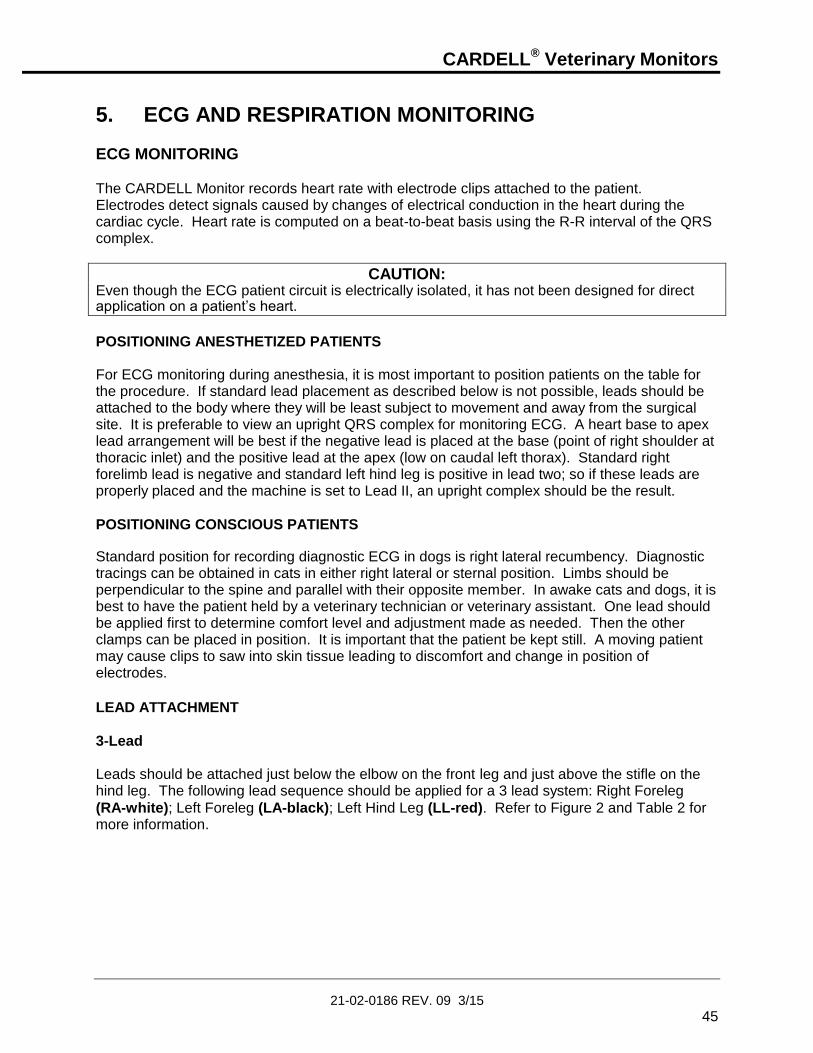
5. ECG AND RESPIRATION MONITORING ECG MONITORING The CARDELL Monitor records heart rate with electrode clips attached to the patient. Electrodes detect signals caused by changes of electrical conduction in the heart during the cardiac cycle. Heart rate is computed on a beat-to-beat basis using the R-R interval of the QRS complex.
CAUTION: Even though the ECG patient circuit is electrically isolated, it has not been designed for direct application on a patient’s heart.
POSITIONING ANESTHETIZED PATIENTS For ECG monitoring during anesthesia, it is most important to position patients on the table for the procedure. If standard lead placement as described below is not possible, leads should be attached to the body where they will be least subject to movement and away from the surgical site. It is preferable to view an upright QRS complex for monitoring ECG. A heart base to apex lead arrangement will be best if the negative lead is placed at the base (point of right shoulder at thoracic inlet) and the positive lead at the apex (low on caudal left thorax). Standard right forelimb lead is negative and standard left hind leg is positive in lead two; so if these leads are properly placed and the machine is set to Lead II, an upright complex should be the result.
POSITIONING CONSCIOUS PATIENTS Standard position for recording diagnostic ECG in dogs is right lateral recumbency. Diagnostic tracings can be obtained in cats in either right lateral or sternal position. Limbs should be perpendicular to the spine and parallel with their opposite member. In awake cats and dogs, it is best to have the patient held by a veterinary technician or veterinary assistant. One lead should be applied first to determine comfort level and adjustment made as needed. Then the other clamps can be placed in position. It is important that the patient be kept still. A moving patient may cause clips to saw into skin tissue leading to discomfort and change in position of electrodes.
LEAD ATTACHMENT
3-Lead Leads should be attached just below the elbow on the front leg and just above the stifle on the hind leg. The following lead sequence should be applied for a 3 lead system: Right Foreleg
(RA-white); Left Foreleg (LA-black); Left Hind Leg (LL-red). Refer to Figure 2 and Table 2 for more information.

CARDELL® Veterinary Monitors
21-02-0186 REV. 09 3/15
46
Figure 2: 3-Lead Placement
NOTE: In order to pick up ECG and Respiration signals, the leads must not be placed on the animal’s legs, but on the left and right chest areas.
Table 2: 3-Lead Color and Coding
USA Standard International Standard
LA = black (Left Foreleg) L = yellow (Left Foreleg)
RA = white (Right Foreleg) R = red (Right Foreleg)
LL = red (Left Hind Leg) F = green (Left Hind Leg)
5-Lead
For a 5 lead system, four limb leads can be applied (RA, LA, RL, and LL) with the exploring lead
(brown) used for diagnostic purposes as needed. Otherwise, the exploring lead may be left unplugged. Refer to Figure 3 and Table 3 for more information.
NOTE: Do not use the 5-Lead Patient Cable for 3-Lead monitoring. A “Leads OFF” message will be displayed. Refer to Section 14, ACCESSORIES for the 3-Lead Patient Cable part number information.

CARDELL® Veterinary Monitors
21-02-0186 REV. 09 3/15
47
Figure 3: 5-Lead Placement
Table 3: 5-Lead Color and Coding
USA Standard International Standard
LA = black (Left Foreleg) L = yellow (Left Foreleg)
RA = white (Right Foreleg) R = red (Right Foreleg)
RL = green (Right Hind Leg) N = black (Right Hind Leg)
LL = red (Left Hind Leg) F = green (Left Hind Leg)
V = brown (explore) C = white (common)
LEAD CONTACT Sites where leads are attached to the body must be properly prepared to optimize contact. Dogs and cats have enough electrolyte material on their skin and hair so that merely moistening lead sites with 70% isopropyl alcohol is appropriate. This will usually be sufficient for ECG recording/monitoring for a short time, 30 to 60 minutes, depending upon the relative humidity. For monitoring during longer periods, an electrode paste should be used. It is best to first wet the hair at the lead attachment site with alcohol; then place paste on the moistened hair and skin. It is important that the paste be in direct contact with skin. For patients with dense undercoat, rub paste with fingers to assure that it has made contact with skin. Crocodile clips are supplied with this monitor and they must open wide enough to firmly but gently grasp the skin.

CARDELL® Veterinary Monitors
21-02-0186 REV. 09 3/15
48
RECORDING 1) Once the electrode clips are in place and the leadwires attached, patient cables and
leadwires must be kept away from the neck area to minimize entanglement and accidental strangulation.
2) Connect the leadwires to the ECG patient cable, matching the colored end of the leadwire to the corresponding color on the cable.
3) Connect the round end of the ECG patient cable to the ECG/RESP connector on the side panel of the monitor.
4) Press the ON/STANDBY pushbutton to turn “ON” the monitor.
5) Check that the monitor is accurately detecting the heartbeat and respiration by watching the monitor to see that the heart and lung visual indicators flash with each heartbeat and breath. When the values have been determined, they will be displayed on the front panel respective as heart rate (HR) and respiration rate (RR).
6) If the heart and lung visual indicators do not correspond to the patient’s heart rate and/or respiration, reposition the electrode clips until the indicators flash in synch with the patient’s heartbeat and breathing. This will help to minimize false alarms.
NOTE: Respiration monitoring, by default, is set to “OFF”. Should Respiration monitoring be required, the feature can be turned “ON”. Refer to Page 96, PARAMETERS MENU for the menu selection.
7) If required, refer to Page 96, PARAMETERS MENU and configure the appropriate
waveform (s) to be viewed and printed.
8) Check the alarm limits and configure them appropriately for the patient. Refer to Page 108, ALARM LIMIT VALUES.
FREEZE TRACES
While viewing the Main display screen the user can select to freeze the traces. Press the FREEZE/PRINT/MAIN pushbutton. The message “Traces Frozen” appears at the top of the Main Display screen. While frozen, the numerics continue to update.
Press again to un-freeze. Traces will remain frozen for sixty (60) seconds if no pushbutton is pressed or if the user enters one of the menu selections.

CARDELL® Veterinary Monitors
21-02-0186 REV. 09 3/15
49
RESPIRATION MONITORING
NOTE: The Respiration parameter in the CARDELL monitor, by default, is set to OFF. Should Respiration monitoring be required, the feature can be turned “ON”. Refer to Page 96, PARAMETERS MENU for the menu selection.
The CARDELL Monitor determines respiration by impedance pneumography. Patient respiration is achieved by applying a low voltage, high frequency AC signal across the active left and right chest ECG leads (LA and RA). The monitor detects changes in thoracic impedance that occur as a result in chest movements. Impedance normally increases with inspiration and decreases with expiration. Electrode placement is crucial to monitoring respiration by the impedance method. The sensitivity of the monitor and its ability to accurately detect respiration is greatly enhanced or impeded by the quality of the electrodes and electrode placement. The following is a general procedure for respiratory monitoring:
1) Check the skin area where the electrodes are to be placed.
2) Observe the patient to determine where the greatest breathing movement occurs on the chest.
3) The leadwires that attach to the electrode clips are color coded for ease of identification. Refer to Table 2 for the lead color based on the lead set being used.
4) The third or ground electrode clip (LL) is placed on the thigh of either rear leg. The ground is a reference electrode allowing for better signal detection.
5) Once the electrode clips are in place and the leadwires attached, patient cables and leadwires must be kept away from the neck area to minimize entanglement and accidental strangulation.
6) Connect the leadwires to the ECG patient cable, matching the colored end of the leadwire to the corresponding dot on the cable.
7) Connect the round end of the ECG patient cable to the ECG/RESP connector on the side panel of the monitor.
8) Press the ON/STANDBY pushbutton to turn “ON” the monitor.
9) Check that the monitor is accurately detecting the heartbeat and respiration by watching the monitor to see that the heart and lung visual indicators flash with each heartbeat and breath.
10) If the heart and lung visual indicators do not correspond to the patient’s heart rate and/or respiration, reposition the electrodes until the indicators flash in synch with the patient’s heartbeat and breathing. This will help to minimize false alarms.

CARDELL® Veterinary Monitors
21-02-0186 REV. 09 3/15
50
11) If required, refer to Page 96, PARAMETERS MENU and configure the appropriate waveform (s) to be viewed and printed.
12) Check the alarm limits and configure them appropriately for the patient. Refer to Page 108, ALARM LIMIT VALUES.

CARDELL® Veterinary Monitors
21-02-0186 REV. 09 3/15
51
DETACHING THE LEADWIRES To remove leadwires from a patient cable, always grasp the strain relief plastic portion of the leadwire. Do not pull the wire itself.
Figure 4: Detaching the Leadwires
REMOVING THE PATIENT CABLE To remove the patient cable from the monitor’s ECG/RESP connector, press and hold down on the release button to unlock the cable and pull straight back. Do not pull on the cable itself.
Figure 5: Removing the Patient Cable
Refer to Section 14, ACCESSORIES for electrode clips and patient cable types and part number information.

CARDELL® Veterinary Monitors
21-02-0186 REV. 09 3/15
52
This page is intentionally left blank

CARDELL® Veterinary Monitors
21-02-0186 REV. 09 3/15
53
6. BLOOD PRESSURE MONITORING
CUFF SELECTION AND APPLICATION The use of properly designed and sized cuffs is essential for the accurate non-invasive measurement of blood pressure. Midmark cuffs are recommended for use with the CARDELL Monitor.
NOTE: CAS recommends the use of Midmark cuffs with the CARDELL Monitor. CAS recommends the use of the inflation hose supplied with the monitor or a replacement from CAS.
The widest cuff that can be placed around the limb should be used. A cuff that is too small for the limb will not supply sufficient occlusion pressure to the artery. This can cause an erroneously high blood pressure reading. Ideally, cuff width should be 40% of the limb circumference. Substitution of a cuff different from that supplied might result in a measurement error.
NOTE: Overlapping the cuff will not affect the measurement results.
For best results, a cuff should be wrapped for a snug fit and be positioned reasonably close to heart level. Measurements made above the level of the heart will give reduced blood pressure readings. Measurements made below the heart level will give increased readings. These errors are mainly due to the weight of the blood.
NOTE: Avoid compression or restriction of the NIBP Inflation Hose. The hose must not be kinked or pinched. It can be placed in any position, but it should be kept off the table surface to avoid equipment vibrations.
WARNING: The cuff should not be applied on a limb being used for an intravenous infusion. Do not place the cuff on any extremity being used for SpO2 monitoring.
See Section 14, ACCESSORIES, for CAS Medical Systems cuff size and part number information.

CARDELL® Veterinary Monitors
21-02-0186 REV. 09 3/15
54
SITE SELECTION Place the patient on a padded surface or chair to provide comfort. Shivering will inhibit the monitor from making a determination.
CUFF PLACEMENT FOR A CAT A cat may be left in its owner’s lap to keep it calm. Measurements are best done in an area of the hospital away from noise and bright lights. The animal may be held so that the front limbs are free for cuff placement. In conscious patients, the tail may be the most appropriate location for placement of the cuff. Cats may be most comfortable in sternal recumbency making the tail a more preferable site. For the median artery on the foreleg, place the cuff around the forelimb, between the elbow and carpus. Hair need not be clipped except when heavily matted. In cats less than five (5) pounds when measurements are difficult to obtain, place the cuff around the leg above the elbow to obtain measurements from the brachial artery. Measurements from the coccygeal artery may be used by placing the cuff around the base of the tail but not in anesthetized patients.
Figure 6: Cat Cuff Placement

CARDELL® Veterinary Monitors
21-02-0186 REV. 09 3/15
55
CUFF PLACEMENT FOR A DOG For measurements in dogs, it is preferable to use the right lateral, sternal or dorsal recumbent positions. That is not a problem in anesthetized patients, but it may be difficult to get large dogs to cooperate for proper positioning. If the dog is in a sitting position, place the front paw on the operator’s knee and take measurements from the metacarpus. Sites for cuff placement are the metacarpus, metatarsus and anterior tibial. In anesthetized patients, most surgeries are done on the posterior part of the body so the metacarpal area of the forelimb is most convenient. In situations where this is not possible, the cuff should be wrapped around the metatarsus just proximal to the tarsal pad or around the hind leg just distal to the hock. The tail site should not be used for cuff placement during anesthesia. If the hair over the artery site is too thick or matted for good contact, it should be clipped.
Figure 7: Dog Cuff Placement
NOTE: Use metacarpus or metatarsus.
To achieve the most accurate readings, it is important to keep the cuff on a horizontal plane with the heart.

CARDELL® Veterinary Monitors
21-02-0186 REV. 09 3/15
56
LARGER ANIMALS A large animal such as a horse should be in a stock, standing still, or lying down. For horses and cows, the cuff can be wrapped around the base of the tail using the coccygeal artery on the ventral surface.
WARNING: When monitoring over an extended period of time, or at frequent intervals, periodically observe the patient’s limb to make sure that the circulation is not impaired for a prolonged period of time.
CUFF SIZE SELECTION The widest cuff that can be placed on the patient, without extending beyond the joint, should be selected. Appropriate sized cuffs may be selected based on published guidelines that cuff width should be 40 – 60% of limb circumference. The cuff should be wrapped for a snug fit. Overlapping the cuff will not affect measurement results. Make sure the hook and loop sections of the cuff are fully engaged when it is wrapped around the limb. If not fully engaged, the cuff will detach during bladder inflation. If that happens, select the next size bigger cuff. Adhesive tape or other material should not be used to secure the cuff.
Figure 8: Full Velcro® Engagement

CARDELL® Veterinary Monitors
21-02-0186 REV. 09 3/15
57
Use the following table as a guide to select the correct size.
Table 4: Small Animal Cuff Selection
Cuff Model
Number
Bladder Size
(Width)
Limb Circumference
Range
SV1 2.0 cm (0.8 in.) 3 – 6 cm (1.2 – 2.4 in.)
SV2 2.5 cm (1.0 in.) 4 – 8 cm (1.6 – 3.1 in.)
SV3 3.0 cm (1.2 in.) 6 – 11 cm (2.4 – 4.3 in.)
SV4 4.0 cm (1.6 in.) 7 – 13 cm (2.8 – 5.1 in.)
SV5 5.0 cm (2.0 in.) 8 – 15 cm (3.1 – 5.9 in.)
Table 5: Large Animal Cuff Selection
Cuff Model
Number
Bladder Size
(Width)
Limb Circumference
Range
SV8 8 cm (3.1 in.) 13 – 20 cm (5.1 – 7.9 in.)
SV10 10.2 cm (4.0 in.) 18 – 26 cm (7.1 – 10.2 in.)
References: Pedersen KM, Butler MA, Ersboll AK, Pedersen HD (2002). Evaluation of an oscillometric blood pressure monitor for use in anesthetized cats. JAVMA 221: 646-650. Sawyer DC, Guikema AH, Siegel EM (2004). Evaluation of a new oscillometric blood pressure monitor in isoflurane anesthetized dogs. Vet Anaesth Analg 31: 27 – 39.
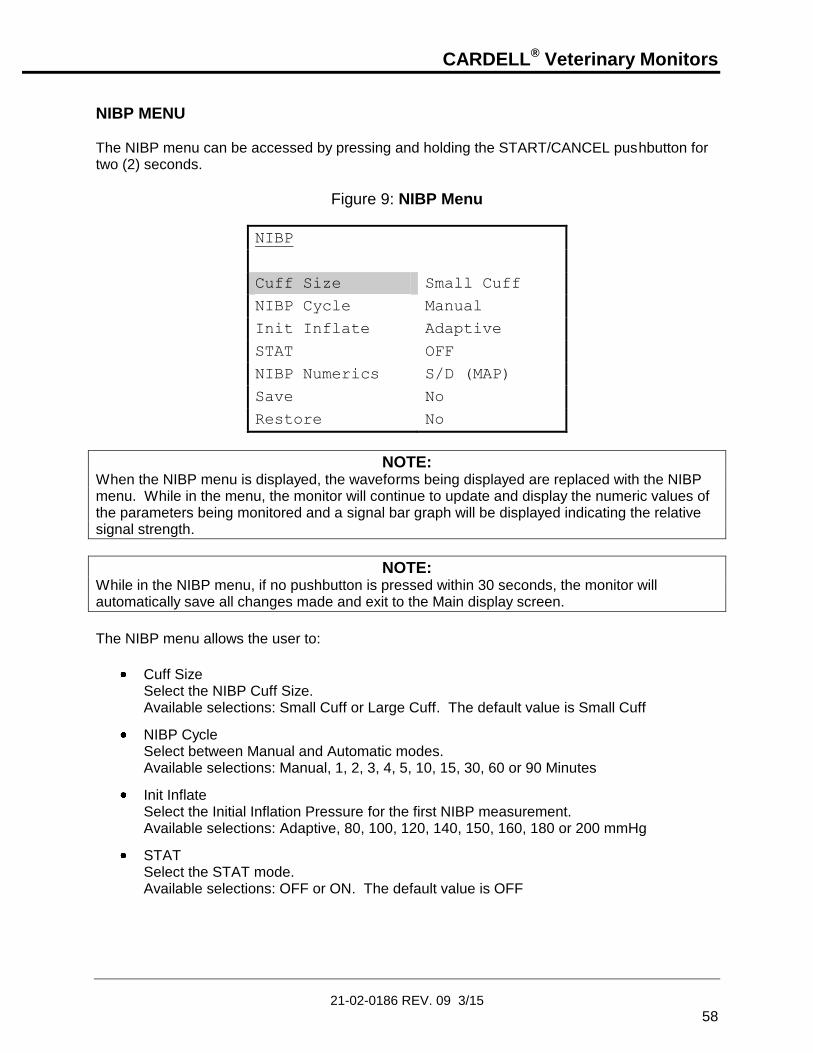
CARDELL® Veterinary Monitors
21-02-0186 REV. 09 3/15
58
NIBP MENU The NIBP menu can be accessed by pressing and holding the START/CANCEL pushbutton for two (2) seconds.
Figure 9: NIBP Menu
NIBP
Cuff Size Small Cuff
NIBP Cycle Manual
Init Inflate Adaptive
STAT OFF
NIBP Numerics S/D (MAP)
Save No
Restore No
NOTE: When the NIBP menu is displayed, the waveforms being displayed are replaced with the NIBP menu. While in the menu, the monitor will continue to update and display the numeric values of the parameters being monitored and a signal bar graph will be displayed indicating the relative signal strength.
NOTE: While in the NIBP menu, if no pushbutton is pressed within 30 seconds, the monitor will automatically save all changes made and exit to the Main display screen.
The NIBP menu allows the user to:
Cuff Size Select the NIBP Cuff Size. Available selections: Small Cuff or Large Cuff. The default value is Small Cuff
NIBP Cycle Select between Manual and Automatic modes. Available selections: Manual, 1, 2, 3, 4, 5, 10, 15, 30, 60 or 90 Minutes
Init Inflate Select the Initial Inflation Pressure for the first NIBP measurement. Available selections: Adaptive, 80, 100, 120, 140, 150, 160, 180 or 200 mmHg
STAT Select the STAT mode. Available selections: OFF or ON. The default value is OFF

CARDELL® Veterinary Monitors
21-02-0186 REV. 09 3/15
59
NIBP Numerics Select how the NIBP numerics are displayed in the NIBP window. Available selections: S/D (MAP), S/D (PR) or (MAP) S/D. The default value is S/D (MAP)
Save Save menu selections into independent veterinary memory locations (Vet 1 and Vet 2). Refer to Page 108 for more information.
Restore Restore a set of menu selections from memory locations (Vet 1 and Vet 2). There is also a provision to restore the Factory Defaults if needed. Refer to Page 109 for more information.
LARGE CUFF / SMALL CUFF OPERATING MODES NIBP function is affected by changing Large Cuff and Small Cuff operating modes. Once the monitor’s power is “ON”, a visual indicator located on the front panel of the monitor, indicates the current operating mode.
IMPORTANT: Prior to patient monitoring, ensure the monitor is configured to the appropriate patient mode – Large Cuff or Small Cuff. The factory default is Small Cuff mode.
To select the cuff size: 1) Press and hold the START/CANCEL pushbutton for two (2) seconds to access the NIBP
menu. The parameter Cuff Size is highlighted.
2) Press one of the NEXT programmed pushbutton keys until the cursor displays the current Cuff Size being used.
3) Use either the ARROW UP or ARROW DOWN pushbutton to make a selection.
4) Once a Cuff Size has been selected, press the MAIN pushbutton to return to the Main display screen. The Cuff Size selected will be displayed in the lower left hand corner of the Main display screen.
MANUAL MODE FOR BLOOD PRESSURE DETERMINATION Select and apply the appropriate sized cuff to the extremity. Refer to Page 56, CUFF SIZE SELECTION, for more information. 1) Connect the cuff to the end of the monitor tubing.
2) Connect the monitor tubing to the NIBP connector, located on the left side of the monitor.
3) The default Initial Inflation Pressure is 150 mmHg for all cuff sizes. To select an alternate Initial Inflation Pressure, press and hold the START/CANCEL pushbutton for two (2) seconds to enter the NIBP menu where the Initial Inflation Pressure can be changed.

CARDELL® Veterinary Monitors
21-02-0186 REV. 09 3/15
60
IMPORTANT: Excessive patient motion can contribute to inaccurate measurements. It is important that the animal be kept still during a measurement. Make every attempt to alleviate fear, anxiety and pain. Stroking the animal before and during the measurement or having the animal held by an assistant may be helpful. Since fear and anxiety may affect the blood pressure, it is advisable to take at least three measurements to allow the animal to relax. Taking five measurements will allow you to discard the upper and lower values and average the middle three.
4) Press the START/CANCEL pushbutton to begin a measurement. For the first measurement the monitor will inflate to the default setting or the Initial Inflation Pressure selected. Within the monitor’s front panel NIBP Numeric Area, the NIBP numeric displays (Systolic, Diastolic and (MAP) or Pulse Rate ) will indicate all dashes “- - -“ while the measurement is in progress and the Inflation Pressure will be displayed in the format “Meas XXX”, where “XXX” is the pressure value.
NOTE: The selection between (MAP) or Pulse Rate is made in the NIBP menu.
For subsequent measurements, the monitor will inflate approximately 30 mmHg higher than the previously determined Systolic pressure. The measurement typically takes less than 30 seconds to complete. In no case will the cuff remain pressurized for more than 150 seconds. When the measurement is completed, the cuff will automatically deflate, the monitor will provide an audio indication and display the NIBP values: Systolic/Diastolic and (MAP) or Systolic/Diastolic and Pulse Rate . Press the START/CANCEL pushbutton, at any time, to stop a measurement and deflate the cuff during the measurement process. The monitor’s front panel NIBP numeric displays will indicate all dashes “- - -“.
NOTE: If any displayed NIBP measurement were to be left on the display for up to twenty-four (24) hours, the monitor will automatically blank the NIBP displays to all dashes “- - -“.

CARDELL® Veterinary Monitors
21-02-0186 REV. 09 3/15
61
AUTOMATIC CYCLE FOR BLOOD PRESSURE DETERMINATION The CARDELL Monitor can automatically take blood pressure measurements at pre-selected time intervals. To choose a time interval: 1) Press and hold the START/CANCEL pushbutton for two (2) seconds to access the NIBP
menu.
2) Press the ARROW DOWN pushbutton until the parameter NIBP Cycle is selected.
3) Press one of the NEXT programmed pushbutton keys until the cursor displays the current NIBP Cycle mode being used.
4) Use either the ARROW UP or ARROW DOWN pushbutton to make a selection.
5) Once a time interval has been selected, press the MAIN pushbutton to return to the Main display screen. The time value selected will be displayed in the NIBP Message Window.
6) Press the START/CANCEL pushbutton to begin the first measurement.
The measurement results are displayed on the front panel until the start of the next measurement cycle. Between each measurement, within the NIBP Numeric Area will be displayed the time remaining until the next measurement, as well as the cycle time chosen in the format "MM:SS CC" where “MM” is the minutes and “SS” is the seconds until the next measurement and “CC” is the cycle time selected.
NOTE: If a measurement is desired between measurement cycles, press the START/CANCEL pushbutton. After this measurement, the monitor will re-enter the Automatic Cycle mode and countdown to the next measurement based on the Automatic Cycle time selected.
To return to the Manual Mode, press and hold the START/CANCEL pushbutton for two (2) seconds to enter the NIBP menu and change the NIBP Cycle back to Manual.

CARDELL® Veterinary Monitors
21-02-0186 REV. 09 3/15
62
STAT MODE
WARNING: Readings obtained during STAT mode may not meet the stated accuracy of this monitor.
WARNING: In some cases, rapid, prolonged cycling of an oscillometric, noninvasive blood pressure monitor cuff has been associated with ischemia. Apply the oscillometric cuff appropriately, according to instructions, and check the cuff site and cuffed extremity regularly when blood pressure is measured at frequent intervals or over extended periods of time.
NOTE: The monitor must be in the Manual NIBP Cycle mode when selecting STAT mode.
The CARDELL Monitor can automatically take a series of blood pressure measurements for a five (5) minute interval with a brief (approx. ten (10) second) pause between determinations to allow venous blood return. To choose the STAT mode: 1) Press and hold the START/CANCEL pushbutton for two (2) seconds to access the NIBP
menu.
2) Press the ARROW DOWN pushbutton until the parameter STAT is selected.
3) Press one of the NEXT programmed pushbutton keys until the cursor displays the current STAT mode being used (OFF).
4) Use either the ARROW UP or ARROW DOWN pushbutton to change the selection to “ON”.
5) Once the STAT mode has been selected, press the MAIN pushbutton to return to the Main display screen. The message “STAT” appears in the NIBP Message Window.
6) Press the START/CANCEL pushbutton to begin the first measurement.
NOTE: Selecting STAT will override any time interval selected for NIBP Cycle in the NIBP menu.
The NIBP Message Window will display "STAT XXX", where “XXX” is the real time cuff pressure. Between readings the NIBP Message Window will display ":XX S" where “XX” is the 10-second count down until the next measurement. After five (5) minutes of determinations the monitor will stop taking measurements, exit the STAT mode and return to the Manual NIBP mode.
CARDELL® Veterinary Monitors
21-02-0186 REV. 09 3/15
63
Pressing the START/CANCEL pushbutton during the STAT Mode will terminate the current NIBP measurement and return the monitor to the STAT mode. The user will then be allowed to exit the STAT mode (OFF) or change the NIBP Cycle to Manual.
WARNING: When monitoring blood pressure over an extended period of time, or at frequent intervals (1 cycle per minute), periodically check the patient’s limb to make sure that the circulation is not impaired beyond the measurement site.
BLOOD PRESSURE REFERENCE VALUES
Which Blood Pressure is Normal in Dogs or Cats?1
It is essential to know the reference range of blood pressure in a given species in order to properly evaluate the animal’s blood pressure and detect hypertension or hypotension. When using different measurement techniques (oscillometry or direct blood pressure measurements), one must also remember that methodological factors influence results. Therefore, technique-specific reference values should be known. Species-specific, breed-specific, and individual differences in normal blood pressure ranges can be observed. The most accurate assessments are made by comparing different blood pressure readings over time using serial measurements made at regular intervals (at least once yearly). This makes it possible to detect the initial signs of related disease (e.g. cardiovascular and renal disease) more sensitively and at an earlier stage. The normal values for dogs and cats are not identical.
FELINE NORMAL VALUES
The blood pressure values for cats are not breed-specific. However, the most sensitive way to detect changes in feline blood pressure is also by comparing individual blood pressure readings taken over time.
Normal feline blood pressure: 124/84
Other investigators have reported comparable reference values:
Feline Reference Values Systolic (mmHg)
Diastolic (mmHg)
125 ± 11 89 ± 9 Brown et al, 1997
123 ± 14 88 ± 15 Curtet, 2001
125 ± 12 86 ± 15 Weber et al, 2002
1 Adapted from “Essential Facts of Blood Pressure in Dogs and Cats,” Egner, Carr & Brown, © 2003
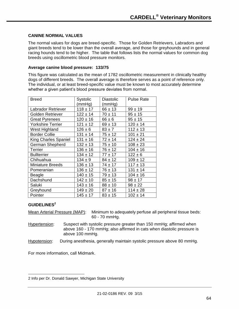
CARDELL® Veterinary Monitors
21-02-0186 REV. 09 3/15
64
CANINE NORMAL VALUES
The normal values for dogs are breed-specific. Those for Golden Retrievers, Labradors and giant breeds tend to be lower than the overall average, and those for greyhounds and in general racing hounds tend to be higher. The table that follows lists the normal values for common dog breeds using oscillometric blood pressure monitors.
Average canine blood pressure: 133/75
This figure was calculated as the mean of 1782 oscillometric measurement in clinically healthy dogs of different breeds. The overall average is therefore serves as a point of reference only. The individual, or at least breed-specific value must be known to most accurately determine whether a given patient’s blood pressure deviates from normal.
Breed Systolic (mmHg)
Diastolic (mmHg)
Pulse Rate
Labrador Retriever 118 ± 17 66 ± 13 99 ± 19
Golden Retriever 122 ± 14 70 ± 11 95 ± 15
Great Pyrenees 120 ± 16 66 ± 6 95 ± 15
Yorkshire Terrier 121 ± 12 69 ± 13 120 ± 14
West Highland 126 ± 6 83 ± 7 112 ± 13
Border Collie 131 ± 14 75 ± 12 101 ± 21
King Charles Spaniel 131 ± 16 72 ± 14 124 ± 24
German Shepherd 132 ± 13 75 ± 10 108 ± 23
Terrier 136 ± 16 76 ± 12 104 ± 16
Bullterrier 134 ± 12 77 ± 17 122 ± 6
Chihuahua 134 ± 9 84 ± 12 109 ± 12
Miniature Breeds 136 ± 13 74 ± 17 117 ± 13
Pomeranian 136 ± 12 76 ± 13 131 ± 14
Beagle 140 ± 15 79 ± 13 104 ± 16
Dachshund 142 ± 10 85 ± 15 98 ± 17
Saluki 143 ± 16 88 ± 10 98 ± 22
Greyhound 149 ± 20 87 ± 16 114 ± 28
Pointer 145 ± 17 83 ± 15 102 ± 14
GUIDELINES2
Mean Arterial Pressure (MAP): Minimum to adequately perfuse all peripheral tissue beds: 60 - 70 mmHg.
Hypertension: Suspect with systolic pressure greater than 150 mmHg; affirmed when above 160 - 170 mmHg; also affirmed in cats when diastolic pressure is above 100 mmHg.
Hypotension: During anesthesia, generally maintain systolic pressure above 80 mmHg.
For more information, call Midmark.
2 Info per Dr. Donald Sawyer, Michigan State University

CARDELL® Veterinary Monitors
21-02-0186 REV. 09 3/15
65
7. PULSE OXIMETRY MONITORING (Model 9403 and 9405) The Pulse Oximeter parameter (SpO2) determines arterial oxyhemoglobin saturation by measuring the absorption of red and infrared light passing through the tissue. Changes in absorption caused by pulsations of blood are used to determine Arterial Saturation (%SpO2) and Pulse Rate (PR).
WARNING: Use only Nellcor® VetSat® veterinary oxygen transducer (sensor and clips). Use of other oxygen transducers may cause improper oximeter performance. Monitors equipped with Nellcor oximetry will have the Nellcor OxiMax® logo next to the SpO2 connector. For more information, refer to the Directions for Use pamphlet included with each Nellcor VetSat sensor.
INSTRUCTIONS FOR USE
NOTE: Reusable sensors may be used on the same site for a maximum of four (4) hours, provided the site is inspected routinely to ensure skin integrity and correct positioning. Because individual skin condition affects the ability of the skin to tolerate sensor placement, it may be necessary to change the sensor site more frequently with some patients.
1) Select a sensor and clip that is appropriate for the patient. There are two (2) sizes of VetSat veterinary sensor clips: model VSC-S (small), and model VSC-L (large).
2) Clean the VetSat sensor and sensor clip separately before and after each use. Refer to Page 139, CLEANING for more information.
3) Open the clip by pressing with the thumb and forefinger.
4) Slide one of the sensor’s alignment buttons along the clip slot until the sensor pad is fully engaged in the clip.
5) Slide the second sensor button along the other clip slot until the second sensor pad is fully engaged in its side of the clip.
NOTE: Check that the VetSat optical sensor pads are facing each other directly.
6) The sensor is now ready to be applied to the patient. The preferred sensor application
site for canine, feline and equine animals is on the tongue, with the sensor’s optical components positioned on the center of the tongue. Alternatively, the sensor and clip may be applied to the animal’s lip, toe, ear, prepuce, or vulva.
NOTE: If the sensor does not track the pulse reliably, it may be incorrectly positioned-or the sensor site may be too thick, thin, or deeply pigmented to permit appropriate light transmission. If any of these situations occurs, reposition the sensor or try another sensor site. If the sensor site is one that is covered with fur, try shaving the site and reapplying the sensor.

CARDELL® Veterinary Monitors
21-02-0186 REV. 09 3/15
66
7) Be sure that the sensor cable is positioned along the side of the animal’s face and body
to avoid entanglement with the animal.
WARNING: Do not use supplemental tape to adhere the clip and sensor directly to the site; this can restrict blood flow and cause inaccurate measurements. For best results, secure the sensor cable independently from the sensor.
8) Connect the sensor assembly to the Interface Cable:
a) Place the plastic hinged cover in the unlocked position (perpendicular to the connector).
b) Connect the sensor assembly to the Interface Cable.
c) Lock the plastic hinged cover to prevent accidental cable disconnection.
Figure 10: Sensor to Interface Cable
9) Plug the Interface Cable into the SpO2 connector on the side panel of the monitor. The connector is shaped like a “D”. Line up the “D” on the Interface Cable with the “D” on the receptacle. Push the cable in until you hear an audible “click”.
10) Press the ON/STANDBY pushbutton to turn “ON” the monitor.
11) Verify that the sensor is properly positioned by observing at least ten seconds of a continuous pleth waveform being displayed across the screen. When a valid signal is detected, the monitor displays the %SpO2 and Pulse Rate values. Should the perfusion light be at a low level, reposition the sensor or try a different sensor. If normal operation cannot be achieved, call a Midmark representative for assistance.
12) If required, refer to Page 96, PARAMETERS MENU and configure the appropriate waveform (s) to be viewed and printed.
13) Check the Alarm Limits and configure them appropriately for the patient. Refer to Page 108, ALARM LIMIT VALUES for more information.
14) If an audio “beep” is required based on the %SpO2, configure the Beep Source to %SpO2 in the Audio/Visual menu and adjust the Beep Volume to the desired level. Refer to Page 99, AUDIO/VISUAL MENU for more information.

CARDELL® Veterinary Monitors
21-02-0186 REV. 09 3/15
67
SatSeconds™ ALARM MANAGEMENT False or nuisance alarms are a common concern with pulse oximetry monitoring. Nuisance alarms are often triggered by minor and brief desaturation events that are clinically insignificant. Clinicians tend to manage these alarms by ignoring them, turning off the alarm or monitor, or widening the alarm limits. The CARDELL Monitor incorporates Nellcor’s SatSeconds Alarm Management feature that offers a better way to manage nuisance alarms without sacrificing patient safety. The SatSeconds function can be activated from the Alarm Limits menu by selecting a SatSeconds limit, or “clock” of 10, 25, 50, 100 or OFF SatSeconds. Clinicians who choose to employ the SatSeconds function should select a limit suited to their clinical environment and patient conditions. Think of SatSeconds as the product of magnitude and time a patient exceeds SpO2 alarm limits. For example, 3 points below the alarm limit for 10 seconds equals 30 SatSeconds. An alarm is only triggered if a desaturation event occurs that reaches the SatSeconds limit you selected. As a safety net, when three or more SpO2 alarm violations occur within 60 seconds, an alarm will sound even if the SatSeconds limit has not been reached.
NOTE: When SatSeconds is set to OFF, the monitor will immediately alarm for %SpO2 limit violations based on the selection made in the Alarm Limits menu.
SENSOR REMOVAL
CAUTION: For the comfort of the patient and to avoid damaging the sensor, do not pull on the cable when removing the sensor and clip from the sensor site.
When SpO2 monitoring is completed, remove the sensor from the patient. To remove the sensor and clip from the patient, press the clip open and remove. When the probe is removed from the patient, the message “SpO2 Probe OFF” is displayed, the Equipment Alarm LEDs are flashing and an audible alarm sounds, indicating a connection has been lost. To acknowledge the alarm, press the SILENCE/RESET pushbutton. The monitor silences the audible and visual alarms and the message “SpO2 Probe OFF” remains on the display.

CARDELL® Veterinary Monitors
21-02-0186 REV. 09 3/15
68
To remove the sensor from the clip, grasp the end of each sensor pad and pull it through to the inside of the clip. The sensor should pop out of the clip easily. DO NOT pull on the cable.
NOTE: If either the 2-Minute Audio Silence or Permanent Audio Silence is enabled, no audio will be heard but a visual message will appear in the Message Window.
REMOVING THE INTERFACE CABLE When SpO2 monitoring is not required, disconnect the Interface Cable by squeezing the grey tabs with your thumb and index finger while pulling the connector away from the monitor.
NOTE: To avoid damage to the Interface Cable, always hold it by the connector rather than the cable when connecting or disconnecting either end. To obtain longer life, avoid excessive kinking or coiling the sensor cable.
When the probe is disconnected from the monitor, the message “No SpO2 Probe” is displayed, the Equipment Alarm LEDs are flashing and an audible alarm sounds, indicating a connection has been broken. To acknowledge the alarm, press the SILENCE/RESET pushbutton. The monitor silences the audible and visual alarms and the message “No SpO2 Probe” is removed from the display.
NOTE: If either the 2-Minute Audio Silence or Permanent Audio Silence is enabled, no audio will be heard but a visual message will appear in the Message Window.
See Section 14, ACCESSORIES for Nellcor oximeter probe types and part number information.
PERFORMANCE CONSIDERATIONS If there is excessive ambient light, cover the sensor site with opaque material. Failure to do so may result in inaccurate measurements. Light sources that can affect performance include surgical lights (especially those with a xeon light source), bilirubin lamps, fluorescent lights, infrared heating lamps and direct sunlight.

CARDELL® Veterinary Monitors
21-02-0186 REV. 09 3/15
69
8. CAPNOGRAPHY MONITORING
(Model 9405)
ORIDION TECHNOLOGY The CARDELL 9405 Monitor is equipped to use Microstream® End Tidal (EtCO2) consumables manufactured by Oridion. No other manufacturer’s consumables should be used.
NOTE: CARDELL 9405 Monitors equipped with Oridion technology will have the Microstream® logo imprinted onto the CO2 connector’s protective cover.
OVERVIEW OF ORIDION MICROSTREAM EtCO2 CONSUMABLES
CAUTION: Microstream consumables are latex free, non-sterile and non-pyrogenic.
CAUTION: Microstream consumables are intended for single patient use only in human medicine, but in the veterinary setting, may be reused as long as any moisture is allowed to dry between uses. Do not attempt to disinfect or flush the consumables as the monitor can be damaged.
NOTE: After use on a patient, the sampling line should be hung to allow any moisture to dry before using again. Multiple sampling lines are included with the monitor to allow one to use fresh, dry lines for each case. Sampling lines should be disposed of immediately upon the first occlusion alarm or after 3-4 months of use. Additional sampling lines may need to be purchased depending on case load.
INTUBATED CONSUMABLES The Microstream® FilterLine products are comprised of a pre-connected sampling line and a “T” tube Airway Adapter. There is a FilterLine® Set (for non-humid environments) and a FilterLine® H Set (for humid environments).
ATTACHING THE INTUBATED CONSUMABLES 1) Slide the protective cover and twist the large-end (female) luer connector into the
CARDELL 9405 Monitor’s Microstream CO2 input connector. Refer to Figure 11 on the following page.

CARDELL® Veterinary Monitors
21-02-0186 REV. 09 3/15
70
Figure 11: CO2 Connection
2) Firmly connect the small-end (male) of the Microstream Airway Adapter to the female-end of the ventilation source.
3) Firmly connect the patient’s endotracheal tube connector into the large (female) of the Microstream Airway Adapter. For a closed suction system, firmly connect the patient’s endotracheal tube connector into the large-end (female) of the Microstream Airway Adapter. Refer to Figure 12 on the following page.
NOTE: Ensure the consumable is not twisted or crimped.

CARDELL® Veterinary Monitors
21-02-0186 REV. 09 3/15
71
Figure 12: Attaching the Airway Adapter
NOTE: During nebulization or suction (when not using closed suction system), in order to avoid moisture buildup and FilterLine occlusion, disconnect the Airway Adapter from the patient’s endotracheal tube.
CAUTION: Loose or damaged connections may compromise ventilation or cause an inaccurate measurement of respiratory gases. Securely connect all components and check connections for leaks.
WARNING: When used with closed suction system, do not place the Airway Adapter between the suction catheter and endotracheal tube.
4) Press the ON/STANDBY pushbutton to turn “ON” the monitor.
NOTE: While the module is initializing (typically 30 to 40 seconds) the monitor shall display the message “CO2 Warm-Up” and dashes “- - -“ will remain in the numeric section.
5) Check that the monitor is accurately detecting CO2 and Respiration by watching the monitor to see that the lung visual indicator flashes with each corresponding breath. Wait for the monitor to determine the initial End Tidal and Respiration Rate values. When the values have been determined, they will be displayed on the front panel respective as EtCO2 (mmHg) and Respiration Rate (RR).

CARDELL® Veterinary Monitors
21-02-0186 REV. 09 3/15
72
6) If the lung visual indicator is not corresponding to the patient’s respiration, reposition the sensor until the indicators flash in synch with the patient’s breathing. This will help to minimize false alarms.
7) If required, refer to Page 96, PARAMETERS MENU and configure the appropriate waveform (s) to be viewed and printed.
NOTE: A library of ten (10) CO2 traces called “CO2 Library” can be selected for viewing in the Trace 3 location of the Parameters menu. Once selected, use the ARROW UP pushbutton to enter the library. Once entered, select a trace to view using the ARROW UP or ARROW DOWN pushbutton. The trace data is displayed at 3 mm/Sec and will remain on the display for 30 seconds before blanking out.
8) Check the alarm limits and configure them appropriately for the patient. Refer to Page 108, ALARM LIMIT VALUES.
Consumables
With “T” Tube Adapter
Endotracheal
Tube Bore
Dead Space
FilterLine Set, Regular (orange) > 4.5 mm < 7.3 cc
FilterLine H Set, Regular (yellow) > 4.5 mm < 7.3 cc
FilterLine H Set, Exotic (yellow) < 4.0 mm < 0.5 cc
Table 6: Specifications for Intubated Consumables – Airway Adapters
NOTE: For more information on what to consider when choosing between airway adapters, refer to Page 171, “Dead Space – Cause, Effect & Control in Small Animal Anesthesia” by Dr. Robert Stein, founder of the Veterinary Anesthesia Support Group (www.VASG.org).

CARDELL® Veterinary Monitors
21-02-0186 REV. 09 3/15
73
REMOVING THE CONSUMABLE When CO2 monitoring is not required, disconnect the consumable by carefully removing the connector from the CO2 input receptacle.
NOTE: To avoid damage to the consumable, always hold it by the connector rather than the tubing when connecting or disconnecting either end.
When the consumable is disconnected from the monitor, the message “CO2 OFF” is displayed, the Equipment Alarm LEDs are flashing and an audible alarm sounds, indicating a connection has been broken. To acknowledge the alarm, press the SILENCE/RESET pushbutton. The monitor silences the audible and visual alarms and the message “CO2 OFF” is removed from the display.
NOTE: If either the 2 Minute Audio Silence or Permanent Audio Silence is enabled, no audio will be heard but a visual indication will appear on the display.
CAUTION: Dispose of Microstream CO2 consumables according to standard operating procedures or local regulations for the disposal of contaminated medical waste.
Refer to Section 14, ACCESSORIES for Oridion consumable types and part number information. Consult instructions enclosed with each consumable for proper application.

CARDELL® Veterinary Monitors
21-02-0186 REV. 09 3/15
74
This page is intentionally left blank

CARDELL® Veterinary Monitors
21-02-0186 REV. 09 3/15
75
9. TEMPERATURE MONITORING
YELLOW SPRINGS INTERNATIONAL (YSI) TECHNOLOGY The CARDELL Monitor is designed to measure temperature to aid in the assessment of thermoregulation.
NOTE: For temperature monitoring a YSI temperature probe and Adapter are required.
To take a Temperature measurement; 1) Consult proper procedure for application of the probe to the patient.
2) Connect the probe to the Temperature Adapter. Connect the Adapter to the TEMP connector on the side panel of the monitor.
3) Press the ON/STANDBY pushbutton to turn “ON” the monitor.
4) Check that the monitor is accurately measuring temperature. When the value has been determined, it will be displayed on the front panel as (oF or oC).
5) Configure the appropriate temperature scale (oF or oC). Refer to Page 95, SELECTING THE TEMPERATURE UNITS.
NOTE: When the Temperature value being measured is greater than 43 oC (109.4 oF), the TEMP numeric value will be displayed as “>>>>>” indicating a value above the monitors temperature range.
NOTE: When no Temperature probe is connected, the TEMP numeric display will be blank.
Refer to Section 14, ACCESSORIES for Temperature probe types and part number information. Consult instructions enclosed with the sensor for proper application.

CARDELL® Veterinary Monitors
21-02-0186 REV. 09 3/15
76
This page is intentionally left blank

CARDELL® Veterinary Monitors
21-02-0186 REV. 09 3/15
77
10. MONITOR OPERATION
FRONT PANEL
Figure 13: Front Panel View
DISPLAY AREAS The Main display area of the CARDELL Monitor can be broken down into seven (7) sections of information. They are:
MAIN DISPLAY AREA
Figure 14: Main Display Area

CARDELL® Veterinary Monitors
21-02-0186 REV. 09 3/15
78
During normal operation, this section (Refer to Figure 14 on the previous page) displays the traces that have been selected in the Parameters menu. Up to three (3) traces can be selected. The traces are displayed in an erase bar format. The CARDELL Monitor automatically selects as Trace #1 an ECG waveform trace. Included with the ECG trace is the ECG Gain selection. This section is also used to display, when selected, the Audio/Visual, History, Limits, Parameters, Service and Setup menus.
TIME, BATTERY AND NUMERIC STATUS
Figure 15: Time, Battery and Numeric Status
This section contains the current monitor time and Battery Charge Status icon. In the models 9403 and 9405, this section displays the numeric values and flashing visual icons for the Heart Rate and Respiration Rate (when enabled). In the model 9404, this section displays the numeric value and a flashing visual icon for the Heart Rate. Also displayed are size markers for both the ECG and Respiration waveforms. The size marker for ECG represents a QRS of 1mV, and the size marker for Respiration represents a breath of 1 Ohm.
NOTE: When Respiration is turned OFF, the RR name, numeric and lung icon will be blank.
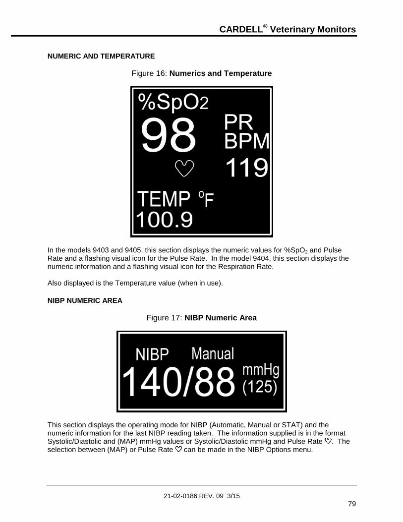
CARDELL® Veterinary Monitors
21-02-0186 REV. 09 3/15
79
NUMERIC AND TEMPERATURE
Figure 16: Numerics and Temperature
In the models 9403 and 9405, this section displays the numeric values for %SpO2 and Pulse Rate and a flashing visual icon for the Pulse Rate. In the model 9404, this section displays the numeric information and a flashing visual icon for the Respiration Rate. Also displayed is the Temperature value (when in use).
NIBP NUMERIC AREA
Figure 17: NIBP Numeric Area
This section displays the operating mode for NIBP (Automatic, Manual or STAT) and the numeric information for the last NIBP reading taken. The information supplied is in the format Systolic/Diastolic and (MAP) mmHg values or Systolic/Diastolic mmHg and Pulse Rate . The selection between (MAP) or Pulse Rate can be made in the NIBP Options menu.

CARDELL® Veterinary Monitors
21-02-0186 REV. 09 3/15
80
EtCO2 NUMERIC SECTION
Figure 18: EtCO2 Numeric
In the model 9405, this section displays the numeric values for both EtCO2 and Respiration Rate and a flashing visual icon for the Respiration Rate. Also displayed, in this example, is a vertical bar graph of relative signal strength.
PATIENT ALARM MESSAGE WINDOW The text section directly below the NIBP information, in Figure 13, displays any patient related alarm messages: example Bradycardia, Tachycardia.
EQUIPMENT MESSAGE WINDOW The text section directly below the End Tidal information, in Figure 13, displays the monitor’s current memory location being used (Vet1 or Vet2), current NIBP operating mode (SmCuff or LgCuff) and will also display, when selected, the current status of the Audio Alarm Silence (2 Minute or Permanent) as well as other Equipment type alarm messages. If a menu selection has been changed in the NIBP, Parameters, Limits or Audio/Visual menus, an asterisk will be displayed: example (Vet1*SmCuff). It will continue to be displayed until all changes have been saved to a memory location.
DISPLAY VISUAL INDICATORS Two (2) light bar visual indicators. One on the left side of the
monitor and one on the right side of the monitor are used for alarm indications.
The Yellow light bar, on the left side, is lit indicating an equipment alarm.
The Red light bar, on the right side, is lit to indicate a patient alarm.

CARDELL® Veterinary Monitors
21-02-0186 REV. 09 3/15
81
A Yellow LED visual indicator used along with the
SILENCE/RESET pushbutton to display the status of the Audio Alarm Silence feature. Refer to Page 114 for more information.
The status of the LED is:
“ON” continuously = 2 Minute Audio Disable
Flash one second “ON”/one second “OFF” = Permanent Audio Disable
A tri-colored LED visual indicator used to display the status of the
power source and battery condition.
The status of the LED is:
GREEN = Monitor is connected to an AC power source
ORANGE = In Use on Battery
RED = Battery Low or Dead Battery

CARDELL® Veterinary Monitors
21-02-0186 REV. 09 3/15
82
FRONT PANEL CONTROLS
Figure 19: Front Panel Controls
ON/STANDBY:
Press once, turns “ON” the CARDELL Monitor’s display (if it was OFF). Press again, turns the monitor’s display “OFF”.
SILENCE/RESET:
When pressed during an active patient alarm, silences the audio portion of that alarm for fifteen (15) seconds. When pressed during an active equipment alarm, the alarm condition shall be acknowledged along with the audio and visual shall be removed. Used to enable and disable the 2 Minute or Permanent Audio Alarm Silence feature. Refer to Page 91, AUDIO ALARM SILENCE (SILENCE/RESET Pushbutton) for more information.

CARDELL® Veterinary Monitors
21-02-0186 REV. 09 3/15
83
NIBP START/CANCEL:
START: Initiates a blood pressure measurement in the Manual Mode or begins the selected Automatic Cycle.
CANCEL: Cancels any active blood pressure function and immediately deflates the cuff.
NIBP OPTION MENU: Press and hold for two (2) seconds to activate.
FREEZE/PRINT/MAIN:
FREEZE:
When pressed while viewing the Main display screen will freeze the traces. The message “Traces Frozen” appears at the top of the Main Display screen. While frozen, the numerics continue to update. Press again to un-freeze. Traces will remain frozen for sixty (60) seconds if no pushbutton is pressed or if the user enters one of the menu selections.
PRINT:
Press and hold for two (2) seconds to print Waveforms, History or Alarm History information.
MAIN:
When pressed while in a sub menu, returns to the Main display screen.
PARAMETERS:
Allows the user to setup and configure how the Parameters being monitored are viewed on the display.
Refer to Page, 96, PARAMETERS MENU for more information.

CARDELL® Veterinary Monitors
21-02-0186 REV. 09 3/15
84
ALARM LIMITS:
Allows the user to enter, set, save and restore the monitor’s Alarm Limits.
Refer to Page 106, PATIENT ALARMS for more information.
HISTORY: Allows the user to review stored patient readings.
Refer to Page, 100, HISTORY for more information.
AUDIO/VISUAL:
Allows the user to setup and configure the Audio and Visual parameters being monitored.
Refer to Page, 99, AUDIO/VISUAL MENU for more information.
ARROW UP:
Allows forward Adjustment (Auto Cycle, History, Inflation Pressure, Limits and Monitor Setup Menus).
Press to cycle through menu selections or press and hold for quicker advance.
ARROW DOWN:
Allows backwards Adjustment (Auto Cycle, History, Inflation Pressure, Limits and Monitor Setup Menus).
Press to cycle through menu selections or press and hold for quicker advance.

CARDELL® Veterinary Monitors
21-02-0186 REV. 09 3/15
85
NEXT The HISTORY and AUDIO/VISUAL pushbutton keys have been
programmed to allow the user to advance horizontally to the next parameter selection in the menus.
PREVIOUS The PARAMETERS and ALARM LIMITS pushbutton keys have
been programmed to allow the user to advance horizontally
backwards to the previous parameter selection in the menus. INFRARED (Ir) DATA PORT An Infrared (Ir) output port, located on the bottom panel of the monitor’s front cover, is available to print Waveforms, History and Alarm data to the optional external printer or other data collection device(s). Maximum distance is approximately three (3) Feet, direct line of sight operation.
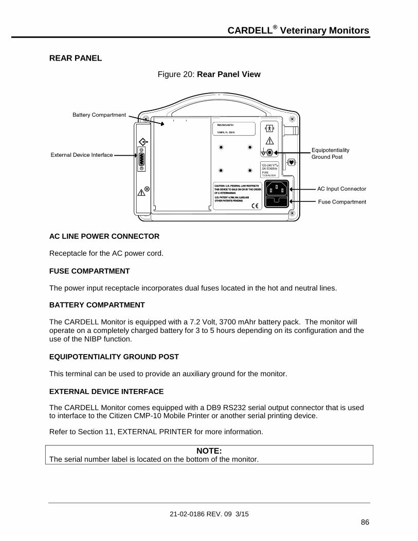
CARDELL® Veterinary Monitors
21-02-0186 REV. 09 3/15
86
REAR PANEL
Figure 20: Rear Panel View
AC LINE POWER CONNECTOR Receptacle for the AC power cord.
FUSE COMPARTMENT The power input receptacle incorporates dual fuses located in the hot and neutral lines. BATTERY COMPARTMENT The CARDELL Monitor is equipped with a 7.2 Volt, 3700 mAhr battery pack. The monitor will operate on a completely charged battery for 3 to 5 hours depending on its configuration and the use of the NIBP function.
EQUIPOTENTIALITY GROUND POST This terminal can be used to provide an auxiliary ground for the monitor.
EXTERNAL DEVICE INTERFACE The CARDELL Monitor comes equipped with a DB9 RS232 serial output connector that is used to interface to the Citizen CMP-10 Mobile Printer or another serial printing device. Refer to Section 11, EXTERNAL PRINTER for more information.
NOTE: The serial number label is located on the bottom of the monitor.

CARDELL® Veterinary Monitors
21-02-0186 REV. 09 3/15
87
LEFT SIDE VIEW
Figure 21: Left Side Panel View
CUFF HOSE CONNECTION The six (6) foot Inflation Hose is connected to the monitor where the MAXNIBP logo is located as shown in Figure 21. The hose must be connected to the cuff prior to use.
TEMP CONNECTOR Connect the adapter and sensor cable in this receptacle for Temperature monitoring.
NELLCOR® VET SpO2 SENSOR CONNECTOR The SpO2 connector is compatible only with Nellcor® VetSat® veterinary sensor. Connect the Interface Sensor cable in this receptacle for SpO2 monitoring.

CARDELL® Veterinary Monitors
21-02-0186 REV. 09 3/15
88
ECG/RESP CONNECTOR The ECG/RESP connector is mechanically keyed to accept only CAS Medical Systems’ 3-Lead or 5-Lead patient cable. Connect either the 3-Lead or 5-Lead Patient Cable in this receptacle for ECG and Respiration monitoring.
CO2 SENSOR CONNECTOR The CO2 consumable is connected to the monitor where the Microstream® logo imprinted onto the CO2 connector’s protective cover is located.
CO2 SCAVENGER EXHAUST PORT To the left of the TEMP connector is the CO2 Scavenger Exhaust Port. The exhaust port is an output intended only for connection to gas collection equipment such as gas scavenger devices.
WARNING: Do not connect sample line or patient input to the exhaust port.

CARDELL® Veterinary Monitors
21-02-0186 REV. 09 3/15
89
MONITOR OPERATING INSTRUCTIONS TURNING THE CARDELL MONITOR “ON” Press the (ON/STANDBY) pushbutton on the front panel to turn the monitor “ON”.
Figure 22: Turning the Monitor On
Each time the monitor is turned “ON”, a brief electronic song will play while the Power On Self-Test (POST) is conducted to ensure that its internal circuits are functioning properly.
NOTE: The user should use the Power On Self Test as a verification tool that all front panel visual indicators and the audio are functioning properly.
Upon applying power to the monitor, verify the following:
The monitor plays its start-up song from the internal speaker.
The two (2) light bars and the Alarm Silence Visual Indicator are turned “ON” twice for one-half second and cycled one after the other.
The monitor displays for three (3) seconds the current monitor start-up screen. The start-up screen consists of the monitor’s Model number and the version of its main DSP software.
NOTE: If the printer was powered “ON” during the monitor’s power-up sequence, the MIDMARK logo is printed.
Once the Power On Self-Test is completed, the monitor’s Main display screen is ready for use. Refer to the Setup and Parameters menus to configure the monitor.

CARDELL® Veterinary Monitors
21-02-0186 REV. 09 3/15
90
SETUP MENU
WARNING: Do not enter the Setup menu while the monitor is connected to a patient. The patient is not being monitored while in the menu.
The monitor’s Setup menu allows the user to tailor the CARDELL Monitor to your individual needs. Once entered, the user can:
Set the Operating Language
Make selections for Audio Alarm Silence
Set the Date
Set the Time
Set Daylight Saving Time Options
Set the SpO2 Pulse Rate Alarm Delay Time
Select the Temperature Units
Select the Trace Background
ENTERING THE SETUP MENU
To enter the monitor’s Setup menu, press and hold the ALARM LIMITS and
AUDIO/VISUAL pushbutton keys while the monitor is being turned “ON” .
Figure 23: Setup Menu
Setup
Language English
Audio Silence 2 Minute
Date 06-Feb-06
Time 08:26
DST OFF
O2 Alarm Delay 10 Sec
TEMP Units °F
Background Dark
NOTE: While in the Setup menu, if no pushbutton is pressed within 60 seconds, the monitor will automatically save all changes made, exit the Setup menu and return to the Main display screen.

CARDELL® Veterinary Monitors
21-02-0186 REV. 09 3/15
91
EXIT THE SETUP MENU When you have completed configuring the monitor, press the MAIN pushbutton to exit and lock in your selection(s). The monitor exits the Setup menu and returns to the Main display screen.
SELECTING THE LANGUAGE The CARDELL Monitor can operate in one (1) of nine (9) languages: English, German, French, Italian, Spanish, Dutch, Swedish Portuguese or Norwegian. To configure the monitor’s operating Language, follow the following procedure: 1) First enter the monitor’s Setup menu. Refer to Page 90, SETUP MENU. The monitor
will automatically highlight the Language parameter.
2) Press one of the NEXT programmed pushbutton keys until the cursor displays the current language being used.
3) Press either the ARROW UP or ARROW DOWN pushbutton to make a selection.
4) Press one of the PREVIOUS programmed pushbutton keys to return back to the parameter selections column. At this time the new language selection shall take effect.
5) Press the ARROW DOWN pushbutton to continue to the next parameter or press the MAIN pushbutton to exit to the Main display screen.
AUDIO ALARM SILENCE (SILENCE/RESET Pushbutton) The CARDELL Monitor’s SILENCE/RESET pushbutton can be configured to have the audio associated with patient alarms set to one of the two selections below. The selections are:
2 Minute (Default)
Permanent To configure the monitor’s Audio Alarm Silence, follow the following procedure: 1) First enter the monitor’s Setup menu. Refer to Page 90, SETUP MENU.
2) Press the ARROW DOWN pushbutton until the parameter Audio Silence is highlighted.
3) Press one of the NEXT programmed pushbutton keys until the cursor displays the audio mode currently being used.
4) Press either the ARROW UP or ARROW DOWN pushbuttons to make a selection.
5) Press one of the PREVIOUS programmed pushbutton keys to return back to the parameter selections column.
6) Press the ARROW DOWN pushbutton to continue to the next parameter or press the MAIN pushbutton to exit to the Main display screen.

CARDELL® Veterinary Monitors
21-02-0186 REV. 09 3/15
92
2 MINUTE AUDIO ALARM SILENCE When the monitor is configured for the 2 Minute Audio Alarm Silence setting, use the SILENCE/RESET pushbutton to “enable or disable” audio alarms for a two (2) minute period. The SILENCE visual bell indicator, located on the front panel of the monitor will be illuminated constantly and the message “2 Minute” will be displayed in the Equipment Message Window section of the display as a reminder when enabled. At the end of two (2) minutes, the monitor will automatically exit the 2 Minute Audio Alarm Silence period and return to normal operation. During a 2 Minute Audio Alarm Silence period, if an alarm (patient or equipment) occurs, except for Low Battery and Dead Battery, the audio alarm remains silenced for the remainder of the two-minutes and only a visual indicator is provided.
PERMANENT AUDIO ALARM SILENCE When the monitor is configured to the Permanent Audio Alarm Silence setting, use the SILENCE/RESET pushbutton to “enable or disable” audio alarms. The SILENCE visual bell indicator, located on the front panel of the monitor will flash at a rate of one (1) second “ON” and one (1) second “OFF” and the message “Permanent” is displayed in the Equipment Message Window section of the display as a reminder when enabled. During a Permanent Audio Alarm Silence period, if an alarm (patient or equipment) occurs, except for Low Battery and Dead Battery, the audio alarm remains silenced and only a visual indicator is provided.
SETTING THE DATE The CARDELL Monitor’s Date value is set at the factory. To configure the monitor’s Date, follow the following procedure: 1) First enter the monitor’s Setup menu. Refer to Page 90, SETUP MENU.
2) Press the ARROW DOWN pushbutton until the parameter Date is highlighted.
3) Press one of the NEXT programmed pushbutton keys until the cursor displays the day parameter currently being used.
4) Press either the ARROW UP or ARROW DOWN pushbutton to make a selection.
5) Press one of the NEXT programmed pushbutton keys until the cursor displays the month parameter currently being used. Month of the Year (Jan, Feb, etc.).
6) Press either the ARROW UP or ARROW DOWN pushbutton to make a selection.
7) Follow steps 5 and 6 to set the year parameter. Last 2 digits of the year (2004 is displayed as 04).
8) Press one of the PREVIOUS programmed pushbutton keys to return back to the parameter selections column.
9) Press the ARROW DOWN pushbutton to continue to the next parameter or press the MAIN pushbutton to exit to the Main display screen.

CARDELL® Veterinary Monitors
21-02-0186 REV. 09 3/15
93
SETTING THE TIME The CARDELL Monitor’s Time value is set for Eastern Time and is set at the factory. To configure the monitor’s Time, follow the following procedure: 1) First enter the monitor’s Setup menu. Refer to Page 90, SETUP MENU.
2) Press the ARROW DOWN pushbutton until the parameter Time is highlighted.
3) Press one of the NEXT programmed pushbutton keys until the cursor displays the hour parameter currently being used. Hour of the Day (0 – 23).
4) Press either the ARROW UP or ARROW DOWN pushbutton to make a selection.
5) Press one of the NEXT programmed pushbutton keys until the cursor displays the minute parameter currently being used. Minute of the Hour (0 – 59).
6) Press either the ARROW UP or ARROW DOWN pushbutton to make a selection.
7) Press one of the PREVIOUS programmed pushbutton keys to return back to the parameter selections column.
8) Press the ARROW DOWN pushbutton to continue to the next parameter or press the MAIN pushbutton to exit to the Main display screen.
NOTE: Altering the Date and Time will affect the History readings, but not erase them.
DAYLIGHT SAVING TIME OPTION The CARDELL Monitor can be configured to automatically respond to time changes associated with Daylight Saving Time. The monitor can be configured to one of five Daylight Saving Time Option settings. They are:
OFF Daylight Saving Time is “OFF”. The user is responsible for changing the time if needed. This is the default setting for the CARDELL Monitor.
N America Daylight Saving Time “North America”. Use this setting and the monitor will automatically change time accordingly to the Daylight Saving Time for countries in North America.
EU 01:00 Daylight Saving Time for all European countries using Greenwich Mean Time.
EU 02:00 Daylight Saving Time for all European countries 1 hour ahead of Greenwich Mean Time.
EU 03:00 Daylight Saving Time for all European countries 2 hours ahead of Greenwich Mean Time.

CARDELL® Veterinary Monitors
21-02-0186 REV. 09 3/15
94
NOTE: Enabling Daylight Saving Time will affect the History readings, but not erase them.
To configure the monitor’s Daylight Savings time setting, follow the following procedure: 1) First enter the monitor’s Setup menu. Refer to Page 90, SETUP MENU.
2) Press the ARROW DOWN pushbutton until the parameter DST is highlighted.
3) Press one of the NEXT programmed pushbutton keys until the cursor displays the parameter currently being used.
4) Press either the ARROW UP or ARROW DOWN pushbutton to make a selection.
5) Press one of the PREVIOUS programmed pushbutton keys to return back to the parameter selections column.
6) Press the ARROW DOWN pushbutton to continue to the next parameter or press the MAIN pushbutton to exit to the Main display screen.
SET THE SpO2 PULSE RATE ALARM DELAY The delay time until an alarm is generated for SpO2 Pulse Rate can be configured to be either zero (0) seconds (no delay) or ten (10) seconds. The default value used by the CARDELL Monitor is ten (10) seconds. To change the monitor’s SpO2 Pulse Rate Alarm Delay Time, follow the following procedure: 1) First enter the monitor’s Setup menu. Refer to Page 90, SETUP MENU.
2) Press the ARROW DOWN pushbutton until the parameter O2 Alarm Delay is highlighted.
3) Press one of the NEXT programmed pushbutton keys until the cursor displays the parameter currently being used.
4) Press either the ARROW UP or ARROW DOWN pushbutton to make a selection.
5) Press one of the PREVIOUS programmed pushbutton keys to return back to the parameter selections column.
6) Press the ARROW DOWN pushbutton to continue to the next parameter or press the MAIN pushbutton to exit to the Main display screen.

CARDELL® Veterinary Monitors
21-02-0186 REV. 09 3/15
95
SELECTING THE TEMPERATURE UNITS The Cardell Monitor can display Temperature readings in either the Celsius (oC) or Fahrenheit (oF) scales. The default value used by the Cardell Monitor is Fahrenheit (oF). To configure the monitor’s Temperature setting, follow the following procedure:
1) First enter the monitor’s Setup menu. Refer to Page 90, SETUP MENU.
2) Press the ARROW DOWN pushbutton until the parameter TEMP Units is highlighted.
3) Press one of the NEXT programmed pushbutton keys until the cursor displays the parameter currently being used.
4) Press either the ARROW UP or ARROW DOWN pushbutton to make a selection.
5) Press one of the PREVIOUS programmed pushbutton keys to return back to the parameter selections column.
6) Press the ARROW DOWN pushbutton to continue to the next parameter or press the MAIN pushbutton to exit to the Main display screen.
TRACE BACKGROUND The background area surrounding the monitor’s waveforms can be displayed either as: a black background with white traces (Dark) or a white background with black traces (Light). The default value used by the CARDELL Monitor is Dark. To configure the monitor’s Trace Background setting, follow the following procedure: 1) First enter the monitor’s Setup menu. Refer to Page 90, SETUP MENU.
2) Press the ARROW DOWN pushbutton until the parameter Background is highlighted.
3) Press one of the NEXT programmed pushbutton keys until the cursor displays the parameter currently being used.
4) Press either the ARROW UP or ARROW DOWN pushbutton to make a selection.
5) Press one of the PREVIOUS programmed pushbutton keys to return back to the parameter selections column.
6) Press the MAIN pushbutton to exit to the Main display screen.

CARDELL® Veterinary Monitors
21-02-0186 REV. 09 3/15
96
PARAMETERS MENU
Figure 24: Parameters Menu
Parameters
mm/Sec
Trace 1 ECG II 25.0
Trace 2 SpO2 25.0
Trace 3 CO2 12.5
Print Traces All 25.0
Print On Alarm OFF
ECG Gain X8
ECG Smoothing ON
ECG Trigger Small Animal
Impedance Resp OFF
EtCO2 Scale 0–50 mmHg
EtCO2 Print OFF
EtCO2 Trace Filled
Save No
Restore No
NOTE: The Parameters pushbutton can be used at any time during monitoring. When the Parameters pushbutton is pressed, the waveforms being displayed are replaced with the Parameters menu. While in the menu, the monitor will continue to update and display the numeric values of the parameters being monitored and a signal bar graph will be displayed indicating the relative signal strength.
NOTE: While in the Parameters menu, if no pushbutton is pressed within 30 seconds, the monitor will automatically save all changes made and exit to the Main display screen.
The Parameter setup menu allows the user to:
Trace 1 Select and configure the waveform to be displayed in the Trace 1 area.
NOTE: An ECG trace will automatically be selected as Trace I I.
Trace 2 Select and configure the waveform to be displayed in the Trace 2 area.
NOTE: When CO2 is selected as Trace 2 or 3, a library of ten (10) CO2 traces called “CO2 Library” can be selected for viewing.

CARDELL® Veterinary Monitors
21-02-0186 REV. 09 3/15
97
Trace 3 Select and configure display data in the Trace 3 area. Available selections: Trace 3 waveform data or History data
NOTE: A continuously updating Trend History menu or a menu of NIBP event readings can be chosen as Trace 3. Refer to Page 102, TREND HISTORY for more information.
Print Traces Select the trace and the speed of the trace which will be printed when an alarm occurs. Available selections: All or ECG (The default value is All)
50.0, 25.0, 12.5, 6.25 mm/Sec (The default value is 25.0)
Print On Alarm Select whether the monitor will automatically print to the recorder when a patient alarm condition occurs. Available selections: OFF or ON (The default value is OFF)
ECG Gain Select the gain size of the ECG Trace. Available selections: Automatic: Manual: Available selections (X.5, X1, X2, X4, X8, X16) (The default value is X8) When Automatic is selected, the monitor’s ECG module selects a gain that adjusts the waveform to be at a pleasing level on the display.
NOTE: The gain value will appear in the upper left hand corner of the Main display screen when the ECG waveform is displayed.
ECG Smoothing Adds Smoothing (Filtering) to low amplitude ECG traces (Manual or Auto Gain at X8 or X16 only) to reduce the amount of baseline noise visible on the display and printed traces. Available selections: OFF or ON (The default setting is ON)
ECG Trigger Select the monitor’s ECG Trigger based on the animals size. Available selections: Small or Large Animal (The default value is Small Animal)
Impedance Resp Configure the Respiration channel Available selections: OFF or ON (The default value is OFF)
EtCO2 Scale Select the scale size of the CO2 waveform trace. Available selections: 0 – 25 mmHg
0 – 50 mmHg (The default value) 0 – 100 mmHg

CARDELL® Veterinary Monitors
21-02-0186 REV. 09 3/15
98
EtCO2 Print Select whether the monitor will automatically print to the recorder a seven (7) second snap shot of the currently selected waveforms when the sensor is connected and when it is disconnected. Based on the Print Traces selections. Available selections: OFF or ON (The default value is OFF)
EtCO2 Trace Select whether the trace will be displayed as a continuous “Line” or displayed with the area below the line as “Filled” in. The printed Recorder trace shall use the “Line” selection. Available selections: Line or Filled (The default value is Filled)
Save Save menu selections into independent veterinary memory locations (Vet 1 and Vet 2). Refer to Page 108 for more information.
Restore Restore a set of menu selections from memory locations (Vet 1 and Vet 2). There is also a provision to restore the Factory Defaults if needed. Refer to Page 109 for more information.
To configure a parameter: 1) Press the PARAMETERS pushbutton. The parameters that are available are listed on
the left hand side of the display. The monitor will initially highlight the Trace 1 parameter.
2) Press one of the NEXT programmed pushbutton keys and highlight the selections column.
3) Press either the ARROW UP or ARROW DOWN pushbutton to make a selection.
4) If Trace 1, 2, or 3 is being configured, press one of the NEXT programmed pushbutton keys to select the speed (mm/Sec) the trace will be viewed at.
5) Press either the ARROW UP or ARROW DOWN pushbutton to make a selection.
6) Press one of the PREVIOUS programmed pushbutton keys to return back to the parameter selections column.
7) Press the ARROW DOWN pushbutton to continue to the next parameter or press the MAIN pushbutton to exit and return to the Main display screen.

CARDELL® Veterinary Monitors
21-02-0186 REV. 09 3/15
99
AUDIO/VISUAL MENU
Figure 25: Audio/Visual Menu
Audio/Visual
Alarm Volume ■■□□□ Beep Source ECG
Beep Volume □□□□□ Contrast ■■■■■■■■□□□ Save No
Restore No
NOTE: The Audio/Visual pushbutton can be used at any time during monitoring. When the Audio/Visual pushbutton is pressed, the waveforms being displayed are replaced with the Audio/Visual menu. While in the menu, the monitor will continue to update and display the numeric values of the parameters being monitored and a signal bar graph will be displayed indicating the relative signal strength.
NOTE: While in the Audio/Visual menu, if no pushbutton is pressed within 30 seconds, the monitor will automatically save all changes made and exit to the Main display screen.
The Audio/Visual setup menu allows the user to:
Alarm Volume Adjust the Alarm Volume level.
The Alarm Volume can be adjusted to one (1) of five (5) volume levels. Altering the Alarm Volume will produce a single tone at the selected volume level.
NOTE: The Volume Level cannot be set to “OFF”.
Beep Source Select the source of the audio “Beep”, when enabled. Available selections: ECG or %SpO2
NOTE: When %SpO2 is selected, the monitor provides a varying pulse beep that will rise with increasing oxygen saturation and fall as saturation decreases.
Beep Volume Adjust the “Beep” Volume level.
The “Beep” Volume can be adjusted to one (1) of five (5) volume levels. Altering the “Beep” Volume will produce a single tone at a selected “non-off” volume level.

CARDELL® Veterinary Monitors
21-02-0186 REV. 09 3/15
100
Contrast Adjust the Contrast level of the display.
Save Save menu selections into independent veterinary memory locations (Vet 1 and Vet 2). Refer to Page 108 for more information.
Restore Restore a set of menu selections from memory locations (Vet 1 and Vet 2). There is also a provision to restore the Factory Defaults if needed. Refer to Page 109 for more information.
To configure a parameter: 1) Press the AUDIO/VISUAL pushbutton. The available items are listed on the left hand
side of the display. The monitor will initially highlight the Alarm Volume selection.
2) Press one of the NEXT programmed pushbutton keys and highlight the selections column.
3) Press either the ARROW UP or ARROW DOWN pushbutton to make a selection.
4) Press one of the PREVIOUS programmed pushbutton keys to return back to the parameter selections column.
5) Press the ARROW DOWN pushbutton to continue to the next parameter or press the MAIN pushbutton to exit and return to the Main display screen.
HISTORY The History pushbutton allows the user to recall stored Trend and Alarm History information. Patient History is organized in two (2) visually displayed lists.
Trend History: Pressing the HISTORY pushbutton the first time reveals the first viewable list that contains up to 480 entries of Trend History. The Trend History contains NIBP readings as they occur along with one (1) minute averages of history data values for Heart Rate (HR), Respiration Rate (RR) when enabled, %SpO2 (%O2), Pulse Rate (PR), CO2 and CO2 Respiration Rate (RR) that are saved once a minute.

CARDELL® Veterinary Monitors
21-02-0186 REV. 09 3/15
101
Alarm History: Once in the History screen, press and hold the HISTORY pushbutton for two (2) seconds to reveal the second viewable list that contains up to 25 entries of Alarm History. The Alarm Type, the High or Low extreme value and the time the alarm occurred are also displayed. Press and hold the HISTORY pushbutton for two (2) seconds returns to the Trend History list.
NOTE: The History pushbutton can be used at any time during monitoring. When the History pushbutton is pressed, the waveforms being displayed are replaced with the History menus. While in the menus, the monitor will continue to update and display the numeric values of the parameters being monitored and a signal bar graph will be displayed indicating the relative signal strength and signal quality at the sensor site.
NOTE: While in the History menus, if no pushbutton is pressed within 30 seconds, the monitor will automatically exit to the Main display screen.
NOTE: Both Trend and Alarm History data are only available for twenty-four (24) hours. Data older than twenty-four (24) hours is automatically removed from the history lists.
Once the HISTORY pushbutton has been pressed, press and hold the HISTORY pushbutton for two (2) seconds to toggle between the two History screens.
NOTE: If no alarms have occurred, the message “No Alarm History” is displayed at the top of the History menu.
When completed, press the MAIN pushbutton to exit and return to the Main display screen or after thirty (30) seconds of button inactivity the monitor will automatically return to the Main display screen.

CARDELL® Veterinary Monitors
21-02-0186 REV. 09 3/15
102
TREND HISTORY
Figure 26: History Menu
History
HR:MN HR %O2 PR CO2 RR 14:02 176 98 174 38 16
14:01 NIBP=153/ 91(123)PR=155
14:01*190 98 189 38 16
14:00 172 98 151 38 16
13:59 NIBP=140/ 88(125)PR=138
13:59 160 98 157 38 16
13:58 128 98 125 38 16
13:57 NIBP=135/ 92(114)PR=163
13:57 160 98 159 38 16
Erase No
To view Trend History: 1) Press the HISTORY pushbutton to enter the Patient History menu.
The most current measurement values and the time of measurement (HR:MN) are highlighted on the front panel display screen. If there were no readings in History, the message "No History" is displayed at the top of the Main display screen when the History pushbutton is first pressed.
NOTE: History data values for NIBP are saved as they occur. One (1) minute averages of history data values for Heart Rate (HR), Respiration Rate (RR) when enabled, %SpO2 (%O2), Pulse Rate (PR), CO2 and CO2 Respiration Rate (RR) are saved once a minute.
NOTE: An * will appear in the Trend History menu indicating an alarm occurred during that minute.
2) Press the ARROW DOWN pushbutton to review preceding measurements. The word
"Oldest Entry" will be displayed briefly at the top of the display indicating there are no more readings remaining for review.
3) Press the ARROW UP pushbutton to advance the measurements towards the most
current measurement taken. The word "Newest Entry" will be displayed briefly at the top of the display indicating you have reached the most current reading.

CARDELL® Veterinary Monitors
21-02-0186 REV. 09 3/15
103
When completed, press the MAIN pushbutton to exit and return to the Main display screen or after thirty (30) seconds of button inactivity the monitor will automatically return to the Main display screen. If a NIBP measurement is desired immediately while in either of the History menus, simply press the START/CANCEL pushbutton. This will exit the History menu and begin a measurement.
NOTE: A continuously updating Trend History menu (History) or a menu of NIBP event readings (NIBP History) can be chosen, in the Parameters Setup menu as Trace 3.
NOTE: Turning the power “OFF” does not clear the History memory. Measurements will remain in memory for up to twenty-four (24) hours. Any measurement older than twenty-four hours is deleted. It is suggested to manually clear History between patients. Refer to ERASING TREND HISTORY on Page 103.
PRINTING TREND HISTORY To Print the Patient History data to the printer:
1) Press the HISTORY pushbutton to enter the Patient History menu.
2) Press and hold the PRINT pushbutton for two (2) seconds. The message “Printing” appears at the bottom of the Display Window as a status indicator.
NOTE: Prior to accessing the Print History mode, the printer should have paper installed and the power turned “ON”. Refer to Section 11, EXTERNAL PRINTER for more information about the printer and sample printout of the History screen.
ERASING TREND HISTORY To Erase the Patient History data:
1) Press the HISTORY pushbutton to enter the Patient History menu.
2) Press one of the NEXT programmed pushbutton keys to advance onto the parameter value to change “Erase No”.
3) Press either the ARROW UP or ARROW DOWN pushbutton until the message “Erase Yes” appears.
4) Press the HISTORY pushbutton again, to erase History data. The monitor erases the memory, enters Alarm History if available, or exits the History menu and returns to the Main display screen.

CARDELL® Veterinary Monitors
21-02-0186 REV. 09 3/15
104
ALARM HISTORY
Figure 27: Alarm History Menu
Alarm Hist
HR:MN Alarm
14:01 Tachycardia: 200 BPM
Erase No
To view Alarm History: 1) Press the HISTORY pushbutton to enter the Patient History menu.
2) Press and hold the HISTORY pushbutton for two (2) seconds to enter the Alarm History menu.
NOTE: If no alarms have occurred, the message “No Alarm History” is displayed at the top of the History menu and no Alarm History menu will be displayed.
3) The most current alarm type, the alarm parameter violated, the High or Low extreme
value of that alarm and the time of the alarm (HR:MN) are highlighted on the front panel display screen.
4) Press the ARROW DOWN pushbutton to review preceding alarms. The word "Oldest Entry" will be displayed briefly at the top of the display indicating there are no more readings remaining for review.
5) Press the ARROW UP pushbutton to advance towards the most current alarm. The word "Newest Entry" will be displayed briefly at the top of the display indicating you have reached the most current reading.
When completed, press the MAIN pushbutton to exit and return to the Main display screen or after thirty (30) seconds of button inactivity the monitor will automatically return to the Main display screen. If a measurement is desired immediately while in either of the History menus, simply press the START/CANCEL pushbutton. This will exit the History menu and begin a measurement.
NOTE: Turning the power “OFF” does not clear the Alarm History memory. Alarms will remain in memory for up to twenty-four (24) hours. Any alarm older than twenty-four hours is deleted. It is suggested to manually clear Alarm History between patients. Refer to ERASING ALARM HISTORY on Page 105.

CARDELL® Veterinary Monitors
21-02-0186 REV. 09 3/15
105
PRINTING ALARM HISTORY To Print the Alarm History data to the printer: 1) Press the HISTORY pushbutton to enter the Patient History menu.
2) Press and hold the HISTORY pushbutton for two (2) seconds to enter the Patient Alarm History menu.
NOTE: If no alarms have occurred, the message “No Alarm History” is displayed at the top of the History menu and no Alarm History menu will be displayed.
3) Press and hold the PRINT pushbutton for two (2) seconds. The message “Printing”
appears at the bottom of the Display Window as a status indicator.
NOTE: Prior to accessing the Print History mode, the printer should have paper installed and the power turned “ON”. Refer to Section 11, EXTERNAL PRINTER for more information about the printer and sample printout of the History screen.
ERASING ALARM HISTORY To Erase the Alarm History data: 1) Press the HISTORY pushbutton to enter the Patient History menu.
2) Press and hold the HISTORY pushbutton for two (2) seconds to enter the Patient Alarm History menu.
NOTE: If no alarms have occurred, the message “No Alarm History” is displayed at the top of the History menu and no Alarm History menu will be displayed.
3) Press one of the NEXT programmed pushbutton keys to advance onto the parameter
value to change “Erase No”.
4) Press either the ARROW UP or ARROW DOWN pushbutton until the message “Erase Yes” appears.
5) Press the HISTORY pushbutton again, to erase Patient Alarm History data. The monitor erases the memory, exits the Alarm History screen and returns to the Patient History display screen, if available, or returns to the Main display screen.

CARDELL® Veterinary Monitors
21-02-0186 REV. 09 3/15
106
REAL TIME CLOCK The CARDELL Monitor uses an internal Real Time Clock to time stamp all entries that are stored in either of its History menus. Changes made to either the time or date settings, should be performed in-between patients being monitored. Refer to Page 92 for Setting the Date and Page 93 for Setting the Time.
PATIENT ALARMS
Figure 28: Alarm Limits Menu
Vet 1 Limits
Low High
HR OFF 290 BPM
%SpO2 88 OFF %
SatSeconds OFF
EtCO2 OFF OFF mmHg
FiCO2 7 mmHg
RR OFF OFF BrPM
No RESP 30 Sec
SYS OFF 240 mmHg
DIA OFF 130 mmHg
MAP 70 140 mmHg
Save No
Restore No
WARNING: The CARDELL Monitors are equipped with non-latching patient alarm(s). As soon as the monitored parameter(s) return within the adjusted limits, the alarm is silenced and reset automatically without any operator interaction.
WARNING: Configuring the CARDELL Monitor’s alarm settings to “OFF” will disable all audible and visual alarms. This mode should only be selected for spot check applications where the patient is receiving bedside surveillance by a trained clinician. Refer to Page 91 AUDIO ALARM SILENCE (SILENCE/RESET Pushbutton) for more information.
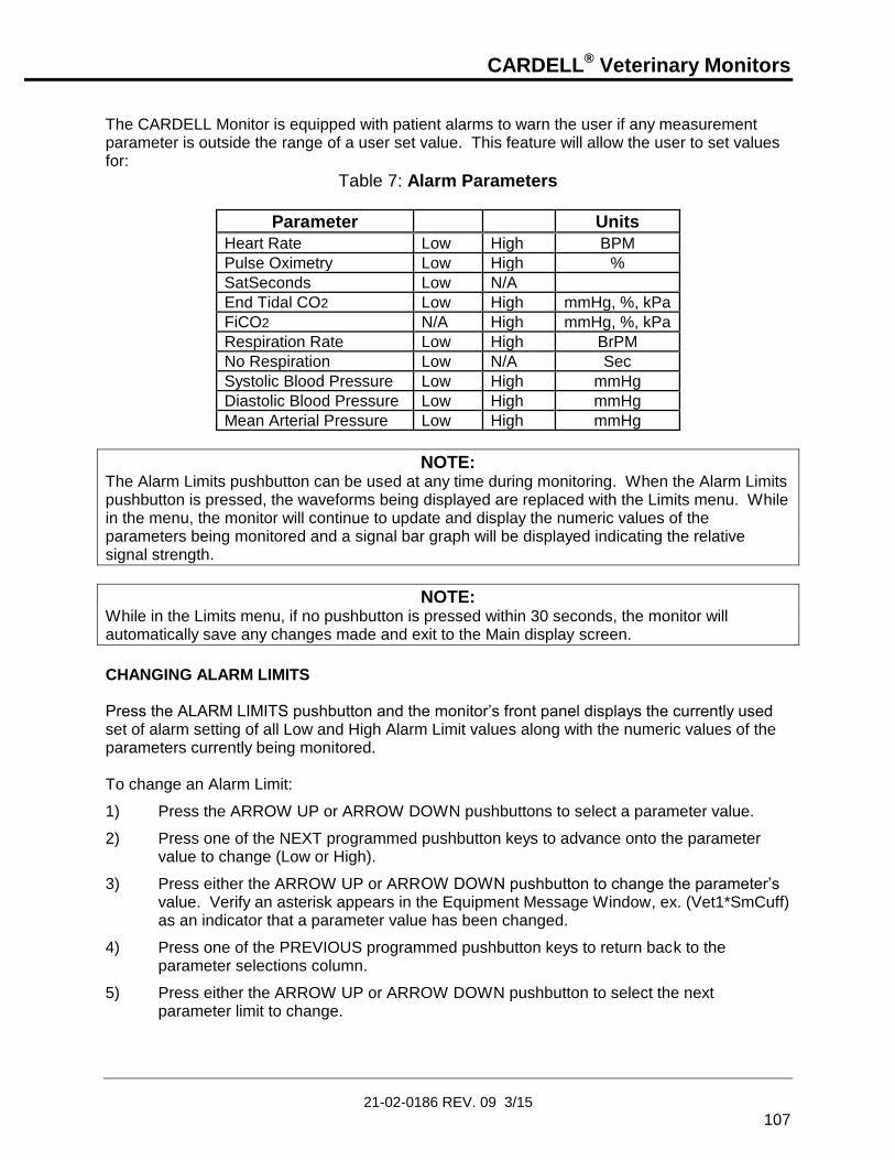
CARDELL® Veterinary Monitors
21-02-0186 REV. 09 3/15
107
The CARDELL Monitor is equipped with patient alarms to warn the user if any measurement parameter is outside the range of a user set value. This feature will allow the user to set values for:
Table 7: Alarm Parameters
Parameter Units
Heart Rate Low High BPM
Pulse Oximetry Low High %
SatSeconds Low N/A
End Tidal CO2 Low High mmHg, %, kPa
FiCO2 N/A High mmHg, %, kPa
Respiration Rate Low High BrPM
No Respiration Low N/A Sec
Systolic Blood Pressure Low High mmHg
Diastolic Blood Pressure Low High mmHg
Mean Arterial Pressure Low High mmHg
NOTE: The Alarm Limits pushbutton can be used at any time during monitoring. When the Alarm Limits pushbutton is pressed, the waveforms being displayed are replaced with the Limits menu. While in the menu, the monitor will continue to update and display the numeric values of the parameters being monitored and a signal bar graph will be displayed indicating the relative signal strength.
NOTE: While in the Limits menu, if no pushbutton is pressed within 30 seconds, the monitor will automatically save any changes made and exit to the Main display screen.
CHANGING ALARM LIMITS Press the ALARM LIMITS pushbutton and the monitor’s front panel displays the currently used set of alarm setting of all Low and High Alarm Limit values along with the numeric values of the parameters currently being monitored. To change an Alarm Limit:
1) Press the ARROW UP or ARROW DOWN pushbuttons to select a parameter value.
2) Press one of the NEXT programmed pushbutton keys to advance onto the parameter value to change (Low or High).
3) Press either the ARROW UP or ARROW DOWN pushbutton to change the parameter’s value. Verify an asterisk appears in the Equipment Message Window, ex. (Vet1*SmCuff) as an indicator that a parameter value has been changed.
4) Press one of the PREVIOUS programmed pushbutton keys to return back to the parameter selections column.
5) Press either the ARROW UP or ARROW DOWN pushbutton to select the next parameter limit to change.

CARDELL® Veterinary Monitors
21-02-0186 REV. 09 3/15
108
When finished, press the MAIN pushbutton to exit and return to the Main display screen or after thirty (30) seconds of button inactivity the monitor will automatically return to the Main display screen. The alarm value(s) set will now be used until power is turned “OFF”.
ALARM LIMIT VALUES Table 8, lists the Alarm Limit Default Values used by the CARDELL Monitor.
Table 8: Factory Default Alarm Values
Parameter Limits
Low High Heart Rate HR 60 180
%SpO2 %SpO2 90 OFF
SatSeconds SatSeconds OFF N/A
EtCO2 EtCO2 20 70
FiCO2 FiCO2 N/A 10
Respiration Rate RR 5 90
No Respiration No RESP 20 N/A
Systolic SYS 80 150
Diastolic DIA 40 100
Mean Arterial MAP 70 140
NOTE: Patient alarms for Systolic, Diastolic and MAP values are produced at the time the measurement is taken. Alarms for Heart Rate have a five (5) second delay. Alarms for EtCO2 have a ten (10) second delay. The alarm for %SpO2 has a zero (0) second or SatSeconds delay. The alarm for Pulse Rate will have a zero (0) second or ten (10) second delay when taken from the SpO2 signal (no ECG).
SAVING MENU SELECTIONS The CARDELL Monitor can save menu selections from the NIBP, Parameters, Limits and Audio/Visual menus into two independent memory locations (Vet 1 or Vet 2). To save menu selections to non-volatile memory:
1) Enter the NIBP, Parameters, Limits or Audio/Visual menus.
2) Press the ARROW DOWN pushbutton and highlight “Save”.
3) Press one of the NEXT programmed pushbutton keys to advance onto the parameter value to change (No).
4) Press either the ARROW UP or ARROW DOWN pushbutton and select a memory location to save (Vet 1).

CARDELL® Veterinary Monitors
21-02-0186 REV. 09 3/15
109
5) Press one of the PREVIOUS programmed pushbutton keys, the message “Saving” appears briefly as a status indicator and the current values will be saved in memory. Verify the asterisk is no longer being displayed in the Equipment Message Window.
When finished, press the MAIN pushbutton to exit and return to the Main display screen or after thirty (30) seconds of button inactivity the monitor will automatically return to the Main display screen. The menu selections will be retained in memory even after the monitor’s power is turned “OFF”. If a second set of menu selections is required, re-enter one of the menus, make your changes, and save the set as (Vet 2).
RESTORE A PREVIOUSLY SAVED SET OF MENU SELECTIONS To restore a previously saved set of menu selections (ex. From Vet 2 to Vet 1):
1) Enter the NIBP, Parameters, Limits or Audio/Visual menus.
2) Press the ARROW DOWN pushbutton and highlight “Restore”.
3) Press one of the NEXT programmed pushbutton keys to advance onto the parameter value to change (No).
4) Press either the ARROW UP or ARROW DOWN pushbutton and select the appropriate memory location the monitor will use.
5) Press one of the PREVIOUS programmed pushbutton keys, the message “Restoring” appears briefly as a status indicator. The restored values will be saved to memory.
When finished, press the MAIN pushbutton to exit and return to the Main display screen or after thirty (30) seconds of button inactivity the monitor will automatically return to the Main display screen. The values will be retained in memory even after the monitor’s power is turned “OFF”.
RESTORE FACTORY DEFAULTS To restore the Factory default settings:
1) Enter the NIBP, Parameters, Limits or Audio/Visual menus.
2) Press the ARROW DOWN pushbutton and highlight “Restore”.
3) Press one of the NEXT programmed pushbutton keys to advance onto the parameter value to change (No).
4) Press either the ARROW UP or ARROW DOWN until the message “Factory” appears.
5) Press one of the PREVIOUS programmed pushbutton keys, the message “Restoring” appears briefly as a status indicator and the Factory Default values will be restored into the current memory location.
When finished, press the MAIN pushbutton to exit and return to the Main display screen or after thirty (30) seconds of button inactivity the monitor will automatically return to the Main display screen. The values will be retained in memory even after the monitor’s power is turned “OFF”.

CARDELL® Veterinary Monitors
21-02-0186 REV. 09 3/15
110
AUDIBLE AND VISUAL INDICATORS The CARDELL Monitor is capable of producing both an audible and a visual indicator for a variety of monitor conditions. The following table provides a cross reference for audible and visual indications.
Table 9: Audible and Visual Indicators
Alarm Condition Priority
Level
Audible Indication Visual Indication
Dead Battery High 3 Beeps followed by 2 Beeps every 10 seconds
The message is displayed continuously on the monitor’s Main display screen. The Equipment Alarm LEDs are flashing. The Battery Power visual indicator is Red.
Patient Alarm Limit Violations
High 3 Beeps followed by 2 Beeps every 10 seconds
The associated numeric display flashes for one second on / one second off for the parameter limit in violation. The Patient Alarm LEDs are flashing. The message is displayed for one second every two to six seconds in the Patient Alarm Message Window section of the display.
Power Failure High 3 Beeps followed by 2 Beeps every 10 seconds
The message is displayed for one second every two to six seconds in the Equipment Message Window
section of the display *. The Equipment Alarm LEDs are flashing.
Low Battery Alarm Medium 3 Beeps every 25 seconds The message is displayed for one second every two to six seconds in the Equipment Message Window
section of the display *. The Battery Charge Status visual indicator is flashing for one second on / one second off on the display. The Equipment Alarm LEDs are flashing. The Battery Power visual indicator is Red.

CARDELL® Veterinary Monitors
21-02-0186 REV. 09 3/15
111
AUDIBLE AND VISUAL INDICATORS (cont)
Table 9: Audible and Visual Indicators
Alarm Condition Priority
Level
Audible Indication Visual Indication
Equipment Alarms Medium 3 Beeps every 25 seconds The appropriate message is displayed for one second on / one second off in either the Waveform section or Equipment Message
Window section of the display *. The Equipment Alarm LEDs are flashing.
NIBP Errors Medium 3 Beeps every 25 seconds The appropriate message is displayed for one second every two to six seconds in the Equipment Message Window section of the
display *. The Equipment Alarm LEDs are flashing.
ECG Heart Beat Low 1 Beep coincides with each received ECG heart rate
Numerics are updated with each received heart rate value.
NIBP Complete Low 1 Beep when blood pressure is completed
Numerics are updated with each blood pressure taken.
SpO2 Pulse Beat Low 1 Beep coincides with each received SpO2 pulse rate
Numerics are updated with each received SpO2 pulse rate value.
Key Click Low 1 Beep associated with each button action
None
* - The message interval time will vary based on what monitor conditions are present. If the Equipment Alarm is associated with a selected waveform being viewed, the Alarm message appears in the Waveform section of the display.
NOTE: Refer to the Tables starting on Page 122 for a listing of messages that may be displayed on the Main display screen.
CLEARING ALARMS The CARDELL Monitor provides to the user an audible and visual indication for both patient and equipment alarm conditions.
WARNING: The CARDELL Monitors are equipped with non-latching patient alarm(s). As soon as the monitored parameter(s) return within the adjusted limits, the alarm is silenced and reset automatically without any operator interaction.

CARDELL® Veterinary Monitors
21-02-0186 REV. 09 3/15
112
ECG HEART RATE ALARMS During either a Low or High ECG Heart Rate Alarm Limit Violation, the monitor flashes the Heart Rate (HR) numeric display and the Patient Alarm LEDs, provides a Patient Alarm Limit Violation audible tone and flashes the appropriate message (Bradycardia or Tachycardia) in the Patient Alarm Message Window section of the display. To acknowledge the alarm and temporarily mute the audio, press the SILENCE/RESET pushbutton. The monitor silences the audible tone for a maximum of fifteen (15) seconds, the parameter in alarm and Patient Alarm LEDs continue to flash on the front panel and the appropriate message will be displayed in the Patient Alarm Message Window section of the display. If the current patient alarm condition becomes inactive during the 15 seconds and then recurs OR a different patient alarm condition occurs during the 15 seconds, the audio alarm is reactivated. If the alarm condition continues uninterrupted for the 15 seconds, the audio alarm is reactivated.
RESPIRATION ALARMS During either a Low or High Respiration Alarm Limit Violation, the monitor flashes the Respiration Rate (RR) numeric display and the Patient Alarm LEDs, provides a Patient Alarm Limit Violation audible tone and flashes the appropriate message (Low RR or High RR) in the Patient Alarm Message Window section of the display. To acknowledge the alarm and temporarily mute the audio, press the SILENCE/RESET pushbutton. The monitor silences the audible tone for a maximum of fifteen (15) seconds, the parameter in alarm and Patient Alarm LEDs continue to flash on the front panel and the appropriate message will be displayed in the Patient Alarm Message Window section of the display. If the current patient alarm condition becomes inactive during the 15 seconds and then recurs OR a different patient alarm condition occurs during the 15 seconds, the audio alarm is reactivated. If the alarm condition continues uninterrupted for the 15 seconds, the audio alarm is reactivated.
%SpO2 ALARMS During either a Low or High %SpO2 Alarm Limit Violation, the monitor flashes the %SpO2 numeric display and the Patient Alarm LEDs, provides a Patient Alarm Limit Violation audible tone and flashes the appropriate message (Low %SpO2 or High %SpO2) in the Alarm Window section of the display. To acknowledge the alarm and temporarily mute the audio, press the SILENCE/RESET pushbutton.

CARDELL® Veterinary Monitors
21-02-0186 REV. 09 3/15
113
The monitor silences the audible tone for a maximum of fifteen (15) seconds, the parameter in alarm and Patient Alarm LEDs continue to flash on the front panel and the appropriate message will be displayed in the Patient Alarm Message Window section of the display. If the current patient alarm condition becomes inactive during the 15 seconds and then recurs OR a different patient alarm condition occurs during the 15 seconds, the audio alarm is reactivated. If the alarm condition continues uninterrupted for the 15 seconds, the audio alarm is reactivated.
SpO2 PULSE RATE ALARMS During either a Low or High SpO2 Pulse Rate Alarm Limit Violation, the monitor flashes the %SpO2 Pulse Rate (PR) numeric display and the Patient Alarm LEDs, provides a Patient Alarm Limit Violation audible tone and flashes the appropriate message (Low SpO2 PR or High SpO2 PR) in the Alarm Window section of the display. To acknowledge the alarm and temporarily mute the audio, press the SILENCE/RESET pushbutton.
NOTE: For SpO2 Pulse Rate alarms to be enabled, the ECG parameter must be in LEADS OFF condition.
The monitor silences the audible tone for a maximum of fifteen (15) seconds, the parameter in alarm and Patient Alarm LEDs continue to flash on the front panel and the appropriate message will be displayed in the Patient Alarm Message Window section of the display. If the current patient alarm condition becomes inactive during the 15 seconds and then recurs OR a different patient alarm condition occurs during the 15 seconds, the audio alarm is reactivated. If the alarm condition continues uninterrupted for the 15 seconds, the audio alarm is reactivated.
EtCO2 ALARMS During either a Low or High End Tidal CO2 Alarm Limit Violation, the monitor flashes the EtCO2 numeric display and the Patient Alarm LEDs, provides a Patient Alarm Limit Violation audible tone and flashes the appropriate message (Low EtCO2 or High EtCO2) in the Alarm Window section of the display. To acknowledge the alarm and temporarily mute the audio, press the SILENCE/RESET pushbutton. The monitor silences the audible tone for a maximum of fifteen (15) seconds, the parameter in alarm and Patient Alarm LEDs continue to flash on the front panel and the appropriate message will be displayed in the Patient Alarm Message Window section of the display. If the current patient alarm condition becomes inactive during the 15 seconds and then recurs OR a different patient alarm condition occurs during the 15 seconds, the audio alarm is reactivated. If the alarm condition continues uninterrupted for the 15 seconds, the audio alarm is reactivated.

CARDELL® Veterinary Monitors
21-02-0186 REV. 09 3/15
114
NIBP PATIENT ALARMS During a NIBP Patient Alarm Limit Violation, the monitor flashes the NIBP numeric display of the parameter in alarm and the Patient Alarm LEDs, provides a Patient Alarm Limit Violation audible tone and flashes the appropriate message (Low or High SYS, Low or High DIA, Low or High MAP) in the Alarm Window section of the display. To acknowledge the alarm, press the SILENCE/RESET pushbutton. The monitor silences the audible tone, the Patient Alarm LEDs and the appropriate alarm message are no longer flashing.
EQUIPMENT ALARMS During an active Equipment Alarm, the monitor displays the alarm parameter in either the Waveform section or the Equipment Message Window section of the display, flashes the Equipment Alarm LEDs and provides an Equipment Alarm audible tone. To acknowledge the alarm, press the SILENCE/RESET pushbutton. The monitor silences the audible and visual alarms and clears the parameter from the display.
NOTE: The Low Battery and Dead Battery alarms cannot be silenced.
2 MINUTE AUDIO ALARM SILENCE
NOTE: Enabling the 2 Minute Audio Silence mode can only be accomplished after all active alarm conditions have been addressed. To clear an alarm, refer to Page 111, CLEARING ALARMS.
If the 2 Minute Audio Silence mode is selected in the Audio Silence portion of the Setup menu, pressing the SILENCE/RESET pushbutton will temporarily deactivate the audio alarms for two (2) minutes. The SILENCE visual indicator will illuminate continuously and the message “2 Minute” will be displayed in the Equipment Message Window section of the display as a reminder.
NOTE: The “2 Minute” message will alternately be displayed with the monitor’s current operating mode.
When the 2 Minute Audio Silence is enabled, the monitor will not alarm for patient related High and Low Alarms, NIBP Errors and Equipment Alarms. The monitor will alarm for Low Battery and Dead Battery. To re-activate the audio alarm, press the SILENCE/RESET pushbutton again. The visual indicators will go out. If the button is not pressed, audible alarms will be re-armed automatically after two (2) minutes. Refer to Page 91, AUDIO ALARM SILENCE (SILENCE/RESET Pushbutton) for more information.

CARDELL® Veterinary Monitors
21-02-0186 REV. 09 3/15
115
PERMANENT AUDIO ALARM SILENCE
NOTE: Enabling the Permanent Audio Silence mode can only be accomplished after all active alarm conditions have been addressed. To clear an alarm, refer to Page 111, CLEARING ALARMS.
If the Permanent Audio Silence mode is selected in the Audio Silence portion of the Setup menu, pressing the SILENCE/RESET pushbutton will deactivate the audio alarms. The SILENCE visual indicator will flash at a rate of one (1) second “ON” and one (1) second “OFF” and the message “Permanent” will be displayed in the Equipment Message Window section of the display as a reminder.
NOTE: The “Permanent” message will alternately be displayed with the monitor’s current operating mode.
When enabled, the monitor will not alarm for patient related High and Low Alarms, NIBP Application Error and Equipment Alarms. The monitor will alarm for Low Battery and Dead Battery. To re-activate the audio alarm, press the SILENCE/RESET pushbutton again. The visual indicators will go out. Refer to Page 91, AUDIO ALARM SILENCE (SILENCE/RESET Pushbutton) for more information.
BATTERY POWER The CARDELL Monitor is equipped with an internal rechargeable battery. The battery is charging whenever the monitor is plugged into the AC wall outlet. A Battery Power Visual Indicator, located on the front panel, indicates the status condition of the monitor’s battery. Batteries will self-discharge when they are not used. It is recommended that the battery be maintained at full charge by leaving the monitor connected to the AC wall outlet whenever possible. The 7.2 Volt 3700 mAhr battery pack, when fully charged, is capable of running the monitor for approximately four (4) hours.
NOTE: Operating time on battery power is based on a Model 9403 monitor when the NIBP is set in the 5-Minute Automatic Mode.
BATTERY MESSAGES When the message "Low Battery" appears in the Equipment Message Window section of the display, at least thirty (30) minutes of battery operation remain and the monitor’s battery pack should be charged as soon as possible.

CARDELL® Veterinary Monitors
21-02-0186 REV. 09 3/15
116
During a Low Battery condition, the monitor flashes the Battery Charge Status visual indicator and the Equipment Alarm LEDs, provides an Equipment Alarm audible tone and flashes the message “Low Battery” in the Alarm Message Window section of the display. Also, the front panel Battery Power visual indicator changes from Orange to Red.
WARNING: Upon the detection of a Low Battery condition and if the battery is not charged by the user, the monitor may no longer function as intended. The monitor should be plugged into a power source as soon as possible and the battery allowed to charge for five (5) hours.
NOTE: A Low Battery alarm cannot be silenced.
When the "Dead Battery" message appears, the battery is no longer able to power the monitor. During a Dead Battery condition, the message "Dead Battery" is displayed continuously on the Main display screen, the Equipment Alarm LEDs are flashing, the Battery Power visual indicator is colored Red and three (3) audio “beeps” followed by two (2) audio “beeps” once every ten (10) seconds are heard until the power is turned off.
WARNING: Upon the detection of a Dead Battery condition and if the monitor is not turned off by the user, the monitor shuts down and turns “OFF” after three (3) minutes of operations.
NOTE: A Dead Battery alarm cannot be silenced.
When either of these messages appears, it is necessary to recharge the battery. A depleted battery may be fully recharged in five (5) hours. The monitor can be used to obtain measurements while the battery is charging.
NOTE: Using the monitor while charging may lengthen the time to restore battery charge.
NOTE: During charging of the battery, the case may feel warm to the touch.

CARDELL® Veterinary Monitors
21-02-0186 REV. 09 3/15
117
CHECKING BATTERY STATUS There are several means to get an indication about the battery charge status:
When the monitor is connected to the AC wall outlet the Battery Charge Status visual indicator will have a moving bar from left to right within the indicator signifies the battery is being charged. Once charged, the moving bar will stop and the battery icon will be completely filled in.
When the monitor is being powered from the battery, the moving bar within the Battery Charge Status visual indicator will be moving from right to left signifying the battery is being discharged.
CAUTION: This product contains a rechargeable battery that is recyclable. Under various state and local laws, it may be illegal to dispose of this battery into the municipal waste stream. Check with your local authorities for instructions on recycling options in your area.
POWER FAIL The CARDELL Monitor incorporates a Power Fail feature. Whenever the power is disconnected from the monitor and the monitor is not allowed to shut down in an orderly fashion, the monitor, when re-powered alerts the user. The message “Power Failure” is displayed in the Equipment Message Window, the Equipment Alarm LEDs are flashing and three (3) audio “beeps” followed by two (2) audio “beeps” are heard every ten (10) seconds. During this condition, all other pushbuttons are inactive except for the ON/STANDBY and SILENCE/RESET. To clear the Power Fail condition, press the SILENCE/RESET pushbutton or properly recycle the monitor’s power.
CARDELL® Veterinary Monitors
21-02-0186 REV. 09 3/15
118
USER MESSAGES
WARNING: The CARDELL Monitors are equipped with non-latching equipment alarm(s). As soon as the monitored parameter(s) return within the adjusted limits, the alarm is silenced and reset automatically without any operator interaction.
The CARDELL Monitor displays a variety of messages to aid the user in monitor operation. If a troubleshooting message is displayed during a measurement, follow the actions listed to correct the situation. If the monitor does not turn on, or exhibits a flashing display and failure to operate, the battery is most likely below the Dead Battery point. Connect the monitor to an AC wall outlet and allow it to charge for five (5) hours.
NOTE: Refer to the Tables starting on Page 122 for a listing of messages that may be displayed on the Main display screen.
If the monitor is in need of repair, it must be referred to the appropriate service personnel. Service performed by unauthorized personnel could be detrimental to the monitor and will void the warranty. For service, contact CAS Medical Systems, Inc.
ECG/RESPIRATION USER MESSAGES If the accuracy of any measurement does not seem reasonable, first check the patient’s vital signs by an alternate method. If one of the leadwires should become disconnected from the patient, the waveform trace(s) will become blank, the message “Leads OFF” will be displayed in the waveform section of the display, the Heart Rate and Respiration Rate numeric displays will show dashes “- - -“, the Equipment Alarm LEDs will flash and three (3) audio “beeps“ are heard every twenty-five (25) seconds for as long as the condition continues. To acknowledge the alarm, press the SILENCE/RESET pushbutton. The monitor silences the audible and visual alarms and the message “Leads OFF” remains on the display. If the ECG/Respiration Module located inside the CARDELL Monitor should fail, the message “ECG Error” or “ECG Module” is displayed, the Heart Rate and Respiration Rate numeric displays will show dashes “- - -“, the Equipment Alarm LEDs will also flash and three (3) audio “beeps“ are heard every twenty-five (25) seconds.
CARDELL® Veterinary Monitors
21-02-0186 REV. 09 3/15
119
To acknowledge the alarm, press the SILENCE/RESET pushbutton. The monitor silences the audible and visual alarms, but the message “ECG Error” or “ECG Module” remains on the display. Should the above problems persist, contact CAS Medical Systems, Inc.
SpO2 USER MESSAGES If the accuracy of any measurement does not seem reasonable, first check the patient’s vital signs by an alternate method.
NOTE: The SpO2 probe must be kept as motionless as possible to make a proper determination. Use the SpO2 waveform display to determine if a strong rhythmic pulse signal is present.
When no oximeter probe is attached to the monitor, the %SpO2 and Pulse Rate numeric displays will show dashes “- - -“, and the signal strength window will be blank.
NOTE: If SpO2 is selected as a waveform parameter, no signal strength bar graph is displayed.
When the probe is connected to the monitor, but is off of the patient, the %SpO2 and Pulse Rate numeric displays will show dashes “- - -“. The message “SpO2 Probe OFF” is displayed, the Equipment Alarm LEDs are flashing and three (3) audio “beeps“ are heard every twenty-five (25) seconds.
NOTE: If SpO2 is selected as a waveform parameter, the message appears in the waveform section of the display. If SpO2 is not selected as a waveform parameter, the message appears in the equipment message window section of the display.
To acknowledge the alarm, press the SILENCE/RESET pushbutton. The monitor silences the audible and visual alarms, but the message “SpO2 Probe OFF” remains on the display. If the message “Chk SpO2 Probe” should appear, verify that the probe being used is not defective by replacing the defective one and trying a different probe. The message “Chk SpO2 Probe” is displayed, the Equipment Alarm LEDs are flashing and three (3) audio “beeps“ are heard every twenty-five (25) seconds.
NOTE: If SpO2 is selected as a waveform parameter, the message appears in the waveform section of the display. If SpO2 is not selected as a waveform parameter, the message appears in the equipment message window section of the display.

CARDELL® Veterinary Monitors
21-02-0186 REV. 09 3/15
120
To acknowledge the alarm, press the SILENCE/RESET pushbutton. The monitor silences the audible and visual alarms, but the message “Chk SpO2 Probe” remains on the display. If the SpO2 Module located inside the CARDELL Monitor should fail, the message “SpO2 Error” or “SpO2 Module” is displayed. The %SpO2 and Pulse Rate numeric displays will show dashes “- - -“, the Equipment Alarm LEDs are flashing and three (3) audio “beeps“ are heard every twenty-five (25) seconds.
NOTE: If SpO2 is selected as a waveform parameter, the message appears in the waveform section of the display. If SpO2 is not selected as a waveform parameter, the message appears in the equipment message window section of the display.
To acknowledge the alarm, press the SILENCE/RESET pushbutton. The monitor silences the audible and visual alarms, but the message “SpO2 Error” or “SpO2 Module” remains on the display. Should any of the above problems persist, contact CAS Medical Systems, Inc.
CO2 USER MESSAGES If the accuracy of any measurement does not seem reasonable, first check the patient’s vital signs by an alternate method. When the message “High FiCO2” appears, the CO2 base line level has shifted above the default level set in the CARDELL Monitor. The message “High FiCO2” is displayed, the Patient Alarm LEDs are flashing and three (3) audio “beeps” followed by two (2) audio “beeps” are heard every ten (10) seconds.
NOTE: If CO2 is selected as a waveform parameter, the message appears in the waveform section of the display. If CO2 is selected as a numeric parameter, the message appears in the equipment message window section of the display.
To acknowledge the alarm, press the SILENCE/RESET pushbutton. The monitor silences the audible and visual alarms, but the message “High FiCO2” remains on the display.

CARDELL® Veterinary Monitors
21-02-0186 REV. 09 3/15
121
If the CO2 Module located inside the CARDELL Monitor should fail, the message “CO2 Error” or “CO2 Module” is displayed. The EtCO2 and Respiration Rate numeric displays will show dashes “- - -“, the Equipment Alarm LEDs are flashing and three (3) audio “beeps“ are heard every twenty-five (25) seconds.
NOTE: If CO2 is selected as a waveform parameter, the message appears in the waveform section of the display. If CO2 is selected as a numeric parameter, the message appears in the equipment message window section of the display.
To acknowledge the alarm, press the SILENCE/RESET pushbutton. The monitor silences the audible and visual alarms, but the message “CO2 Error” or “CO2 Module” remains on the display. Should the above problems persist, contact CAS Medical Systems, Inc.
When the message “Cal CO2” appears, the CO2 Hours to Calibration value, displayed in the monitor’s SERVICE menu, equals zero (0). The message “Cal CO2” is displayed in the Equipment Message area of the display and will alternate with the monitor’s current operating mode. No other audible or visual alarm indications will be made. The module will continue to function normally. This is an indicator that it is time to Calibrate the module. Refer to Page 146, CO2 CALIBRATION CHECK for more information.
When the message “Service CO2” appears, the CO2 Hours to Service value, displayed in the monitor’s SERVICE menu, equals zero (0). The message “Service CO2” is displayed in the Equipment Message area of the display and will alternate with the monitor’s current operating mode. No other audible or visual alarm indications will be made. The module will continue to function normally. This is an indicator that it is time to Service the module. For more information, contact CAS Medical Systems, Inc.
NIBP USER MESSAGES If the accuracy of any measurement does not seem reasonable, first check the patient’s vital signs by an alternate method. If the NIBP Module located inside the CARDELL Monitor should fail, the message “NIBP Error” or “NIBP Module” is displayed, the NIBP and MAP numeric displays will show dashes “- - -“, the Equipment Alarm LEDs are flashing and three (3) audio “beeps“ are heard every twenty-five (25) seconds. To acknowledge the alarm, press the SILENCE/RESET pushbutton. The monitor silences the audible and visual alarms, but the message “NIBP Error” or “NIBP Module” remains on the display. Should the above problems persist, contact CAS Medical Systems, Inc.

CARDELL® Veterinary Monitors
21-02-0186 REV. 09 3/15
122
MONITOR MESSAGES
MONITOR
Table 10: Monitor Messages
MONITOR
MESSAGE
POSSIBLE CAUSE POSSIBLE SOLUTION
“Clock Battery” The monitor’s internal clock battery is almost discharged.
Contact CAS Medical Systems to have the monitor serviced.
"Dead Battery" The battery is fully discharged.
Recharge the battery for at least 5 hours.
"Low Battery" The battery is almost discharged.
At least 30 minutes of operation is available from when the message first appears. Recharge the battery as soon as possible.
"System Error" An electronic failure has occurred within the monitors’ Main Board.
Contact CAS Medical Systems to have the monitor serviced.
"Power Failure" Power was disconnected from the monitor.
Press the SILENCE/RESET pushbutton to clear the message.
OR Turn the monitor Off, then back On to clear the message.
“Set Clock” The monitor’s clock needs to be set.
The monitor’s time and date values are incorrect. Refer to Page 92 for information to set the Date and Page 93 to set the Time. The monitor’s internal clock battery needs to be replaced. Contact CAS Medical Systems.

CARDELL® Veterinary Monitors
21-02-0186 REV. 09 3/15
123
MONITOR MESSAGES (cont.)
ECG/RESPIRATION
Table 11: ECG/Respiration Monitor Messages
MONITOR
MESSAGE
POSSIBLE CAUSE POSSIBLE SOLUTION
“ECG Error” A communication failure has occurred with the monitors’ ECG Board.
Turn the monitor Off; disconnect the AC Line cord and battery. Reconnect the battery and AC Line cord, turn the monitor On. If the message still appears, contact CAS Medical Systems to have the monitor serviced.
“ECG Module” An electronic failure has occurred within the monitors’ ECG Board.
Contact CAS Medical Systems to have the monitor serviced.
“Leads OFF” The leadwires may be disconnected. The patient cable may be disconnected. The leadwires or patient cable may be broken. The electrodes may be old.
Check the leadwires at the electrode end and at the patient cable to be sure they are connected securely. Check the patient cable jack on the monitor to be sure it is plugged in securely. Replace the leadwires or patient cable. Replace the electrodes.

CARDELL® Veterinary Monitors
21-02-0186 REV. 09 3/15
124
MONITOR MESSAGES (cont.)
NIBP
Table 12: NIBP Monitor Messages
MONITOR
MESSAGE
POSSIBLE CAUSE POSSIBLE SOLUTION
"Air Leak" Air leak in cuff/hose/monitor pneumatic system.
Check that the cuff/hose/monitor connection is secure. Check cuff for leaks. Do not use a known leaky cuff.
“Appl Error“ Small cuff is detected in Large Cuff mode.
Check cuff. Replace cuff or change operating mode.
"Flow Error" Stable cuff pressure cannot be maintained by the NIBP pneumatic system.
Check the external tube for kinks. Perform a Pneumatic Check as detailed in the Maintenance section of this manual. Replace cuff.
"Loose Cuff" Cuff applied too loosely. Check cuff for proper fit on patient.
"Motion" There was too much extremity motion for the monitor to accurately complete the NIBP measurement in 150 seconds.
Measurements can be obtained when there is limited extremity movement, but the measurement time may be extended. Measurement time is limited to 150 seconds. Restrain patient extremity motion.
"NIBP Cal" Pressure calibration data corrupted within NIBP module.
Pressure module needs recalibration. Contact CAS Medical Systems to have the monitor serviced.
"NIBP Error" An electronic failure has occurred within the NIBP module.
Turn the monitor Off; disconnect the AC Line cord and battery. Reconnect the battery and AC Line cord, turn the monitor On. If the message still appears, contact CAS Medical Systems to have the monitor serviced.
"NIBP Module" The NIBP Module installed is not compatible with the monitor.
Contact CAS Medical Systems to have the monitor serviced.

CARDELL® Veterinary Monitors
21-02-0186 REV. 09 3/15
125
MONITOR MESSAGES (cont.)
NIBP (cont.)
Table 12: NIBP Monitor Messages
ERROR
MESSAGE
POSSIBLE CAUSE POSSIBLE SOLUTION
"Over Press" Cuff pressure exceeded 290 mmHg.
Very rapid squeezing of the cuff can cause this error. Repeat the measurement. If this message repeatedly occurs during normal use, the monitor must be serviced.
"Range Error" The systolic reading exceeds the measurement range of 265 mmHg.
Repeat measurement. If the message is displayed again, use another method to measure the patient’s blood pressure.
“Signal Sat” Motion pulses too strong. Limit patient activity; the arm must be still and/or relaxed. Repeat measurement.
"Time Out" The monitor was unable to complete a measurement within 150 seconds.
An extremely long measurement can be due to a loose cuff, high blood pressure, or monitor re-pumps. Try measurement again. Try higher initial pressure. If message consistently reappears try using another means to obtain patient's blood pressure.
"Weak Signal" The monitor did not detect any pulses during a NIBP measurement.
Check the fit of the cuff. Repeat measurement.

CARDELL® Veterinary Monitors
21-02-0186 REV. 09 3/15
126
MONITOR MESSAGES (cont.)
SpO2
Table 13: SpO2 Monitor Messages
MONITOR
MESSAGE
POSSIBLE CAUSE POSSIBLE SOLUTION
“Chk SpO2 Probe” The monitor is questioning the quality of the signal being received by the SpO2 sensor. The sensor is receiving too much ambient light.
Verify that the sensor is being used according to the manufacturer’s recommendations. Verify that the sensor emitter and detector are parallel to and directly opposing each other.
“No SpO2 Probe” The monitor is not detecting the SpO2 probe.
The probe was disconnected from either the Interface Cable or from the monitor.
“Pulse Search” The monitor is searching for a Pulse signal.
Normal at power-up as the monitor searches for a pulse. The probe position may have changed. Check the probe site.
“Probe Error” The SpO2 probe being used is not the correct one for the monitor’s configuration.
Verify the probe being used is the correct probe.
"SpO2 Error" An electronic failure has occurred within the SpO2 module.
Turn the monitor Off; disconnect the AC Line cord and battery. Reconnect the battery and AC Line cord, turn the monitor On. If the message still appears, contact CAS Medical Systems to have the monitor serviced.
"SpO2 Module" An electronic failure has occurred within the monitors’ SpO2 module.
Contact CAS Medical Systems to have the monitor serviced.
“SpO2 Probe OFF” The monitor is no longer receiving a patient signal from the SpO2 probe.
The probe is no longer in contact with the patient. Check the probe site.

CARDELL® Veterinary Monitors
21-02-0186 REV. 09 3/15
127
MONITOR MESSAGES (cont.)
CO2
Table 14: CO2 Monitor Messages
MONITOR
MESSAGE
POSSIBLE CAUSE POSSIBLE SOLUTION
“Blocked Line” The CO2 module has attempted to purge the line with no success.
Disconnect the consumable. Check the consumable tube for kinks and/or blockages. Replace the consumable.
“Cal CO2” The CO2 module’s calibration timer has reached zero hours.
Perform a CO2 calibration check. Refer to Page 146, CO2 CALIBRATION CHECK.
“Chk CO2 Flow” The CO2 module has detected a blockage in the exhaust port.
Check the exhaust port and tubing for kinks and/or blockages.
“Clearing Line” The CO2 module has detected an occlusion in its input and is attempting to purge the line.
Check the consumable tube for kinks and/or blockages.
“CO2 Error” A communication failure has occurred with the monitors’ CO2 Board.
Turn the monitor Off; disconnect the AC Line cord and battery. Reconnect the battery and AC Line cord, turn the monitor On. If the message still appears, contact CAS Medical Systems to have the monitor serviced.
“CO2 Module” An electronic failure has occurred within the monitors’ CO2 Board.
Contact CAS Medical Systems to have the monitor serviced.
“CO2 OFF” The monitor is no longer receiving a patient signal from the CO2 consumable.
The consumable is no longer connected to the monitor.
“Service CO2” The CO2 module’s service timer has reached zero hours.
The monitor will continue to function. Contact CAS Medical Systems to arrange for service.

CARDELL® Veterinary Monitors
21-02-0186 REV. 09 3/15
128
This page is intentionally left blank

CARDELL® Veterinary Monitors
21-02-0186 REV. 09 3/15
129
11. EXTERNAL PRINTER The following section is provided as an overview of the Citizen CMP-10 Mobile Printer as it is used with the CARDELL Monitor.
NOTE: For more detailed information on the Citizen Model CMP-10 Mobile Printer, refer to the User’s Manual that was supplied with the printer.
WARNING: The CARDELL Monitor has been tested with the Citizen CMP-10 Mobile printer to comply with IEC 60601-1-1 and is the only printer that is recommended to be used with the monitor. If another printer is to be used, the user must read the Warning on Page 39 under LEAKAGE CURRENT TEST and follow the guidance given.
NOTE: The CARDELL Monitor is not equipped with interfaces to remote equipment or network(s) to duplicate alarms.
PRINTER OVERVIEW The Citizen CMP-10 Mobile Printer interfaces to the CARDELL Monitor via an Infrared (Ir) port or by using the direct connect RS232 cable (supplied with printer). The Infrared ports are located on the top of the printer and on the bottom front panel of the CARDELL Monitor. When using the Infrared port, it is important to keep the two devices close together (less than three (3) Feet/one (1) Meter) and in-line to maintain proper communications. The monitor can perform a communication test to verify the Infrared connection. Refer to Page 146, IrDA TEST for more information.
CAUTION: For safe and proper usage of the external printer, please observe the following:
When using the printer:
Avoid placing monitor in areas where fluid may enter the printer opening accidentally.
Do not drop or bump the monitor.
Avoid places subject to high or low temperature extremes.
Avoid direct sunlight.
Avoid dusty places and where corrosive gasses are generated.
Never attempt to dismantle or repair the printer mechanism. When handling the thermal paper:
Store in a dark, cool and dry place.
Do not place near organic solvents.
Avoid contact with vinyl chloride films erasers or adhesive tapes for extended periods.
Avoid exposure to high temperature, humidity, liquid, or sunlight.
Always use specified thermal paper (P/N 28-02-0077).

CARDELL® Veterinary Monitors
21-02-0186 REV. 09 3/15
130
PRINTER CONTROLS AND INDICATORS
Figure 29: Printer Controls and Indicators
LED Indicators (Bicolor – Red and Green) 1. CHARGE LED Red on - Charging Battery Green on - Battery is fully charged 2. Power (Error) LED Green on - Device is switched “ON” or self-testing is in progress
Red/Green blinking fast - End of paper Red/Green blinking slow - Print Head Overheated
Controls 3. Infrared (IrDA) port 4. RS 232 Serial Port 5. Power ON/OFF switch 6. Line Feed button press once for one (1) line paper feed press down and hold for continuous paper feed to any length 7. Paper Cover Release Button - Press down to open cover 8. Paper Cutting Edge 9. Paper Cover

CARDELL® Veterinary Monitors
21-02-0186 REV. 09 3/15
131
PRINTER OPERATION
DIRECT CONNECTION The monitor uses the DB9 connector, located on the rear panel of the monitor to interface to the RS232 port on the printer. Use the cable which is supplied with the printer.
NOTE: When using the direct connect method, connect the printer’s serial cable to the printer before turning the printer on.
INFRARED CONNECTION
NOTE: When using the infrared port, disconnect the printer’s serial cable from the printer before turning the printer on.
Position the printer’s IrDA port window in-line with the IrDA window of the CARDELL Monitor OR connect the RS232 direct cable from the printer to the 9-pin RS 232 connector, located on the rear panel of the CARDELL Monitor.
NOTE: When using the IrDA port for printing, it is recommended to keep all items clear of the communications path between the monitor and the printer.
Turn the printer “ON”. To turn the printer “ON”, press and hold the ON/OFF pushbutton for one (1) second. The Power LED illuminates Green. To turn the printer “OFF”, press and hold the ON/OFF pushbutton. The Power LED will illuminate Red and change back to Green. When the LED illuminates Green, remove your finger from the pushbutton.
NOTE: If the printer was powered “ON” during the monitor’s power-up sequence, the MIDMARK logo is printed.
The CMP-10 Mobile Printer contains an Auto Power Off feature. If the monitor and printer become separated and after ten (10) minutes during which no data has been sent to the printer and the Line Feed (LF) pushbutton has not been pressed, the printer will automatically shutoff. The CARDELL Monitor will periodically send to the printer a “wake-up” message that will disable the Auto Power Off feature.

CARDELL® Veterinary Monitors
21-02-0186 REV. 09 3/15
132
Sample printouts of both History Modes are shown below.
Figure 30: History Sample Printouts
94XX Series Monitor
22-Aug-06 13:33
Patient: _______________________
Notes: _________________________
________________________________
History:
HR:MN HR RR %O2 PR CO2 RR
13:57 160 28 98 159 38 29
13:57 NIBP=135/ 92 (114)PR=156
13:58 128 22 98 125 38 23
13:59 160 26 98 157 39 26
13:59 NIBP=140/ 88 (125)PR=125
14:00 172 25 98 171 37 24
14:01*190 35 98 189 38 34
14:01 NIBP=153/ 91 (123)PR=191
14:02 176 23 98 174 37 24
94XX Series Monitor
22-Aug-06 13:39
Patient: _______________________
Notes: _________________________
________________________________
Alarm Hist:
HR:MN Alarms
14:01 Tachycardia: 200 BPM
NOTE: An asterisk (*) appears in the History printout to indicate an Alarm has occurred during that one-minute time frame. The alarm value shown represents the extreme value during the alarm time.
NOTE: When Respiration is turned OFF, no Respiration Rate (RR) readings will appear.
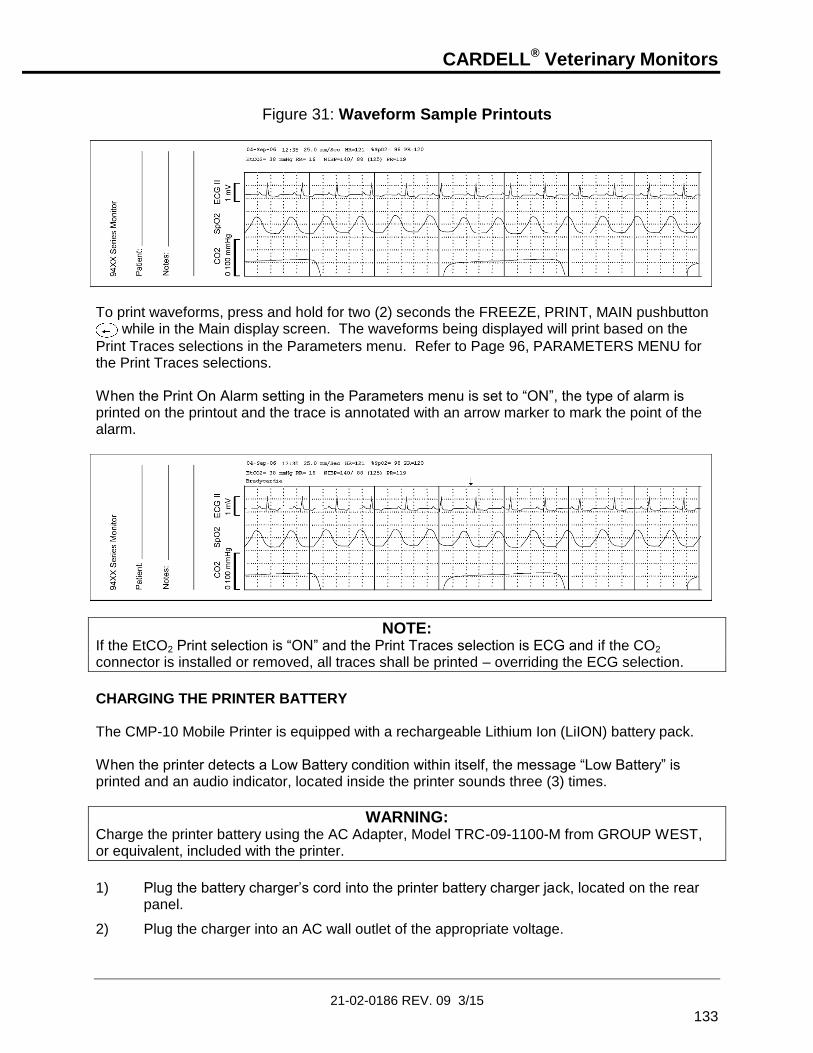
CARDELL® Veterinary Monitors
21-02-0186 REV. 09 3/15
133
Figure 31: Waveform Sample Printouts
To print waveforms, press and hold for two (2) seconds the FREEZE, PRINT, MAIN pushbutton
while in the Main display screen. The waveforms being displayed will print based on the
Print Traces selections in the Parameters menu. Refer to Page 96, PARAMETERS MENU for the Print Traces selections. When the Print On Alarm setting in the Parameters menu is set to “ON”, the type of alarm is printed on the printout and the trace is annotated with an arrow marker to mark the point of the alarm.
NOTE: If the EtCO2 Print selection is “ON” and the Print Traces selection is ECG and if the CO2 connector is installed or removed, all traces shall be printed – overriding the ECG selection.
CHARGING THE PRINTER BATTERY The CMP-10 Mobile Printer is equipped with a rechargeable Lithium Ion (LiION) battery pack. When the printer detects a Low Battery condition within itself, the message “Low Battery” is printed and an audio indicator, located inside the printer sounds three (3) times.
WARNING: Charge the printer battery using the AC Adapter, Model TRC-09-1100-M from GROUP WEST, or equivalent, included with the printer.
1) Plug the battery charger’s cord into the printer battery charger jack, located on the rear
panel.
2) Plug the charger into an AC wall outlet of the appropriate voltage.
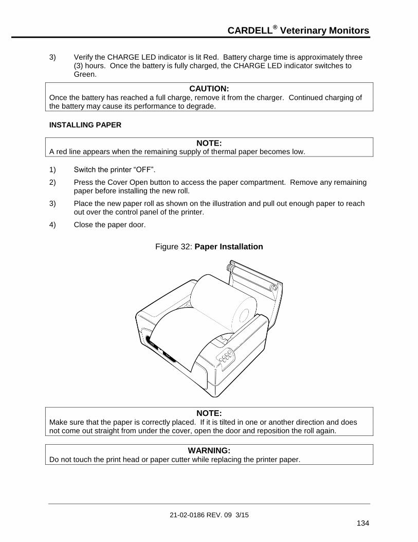
CARDELL® Veterinary Monitors
21-02-0186 REV. 09 3/15
134
3) Verify the CHARGE LED indicator is lit Red. Battery charge time is approximately three
(3) hours. Once the battery is fully charged, the CHARGE LED indicator switches to Green.
CAUTION: Once the battery has reached a full charge, remove it from the charger. Continued charging of the battery may cause its performance to degrade.
INSTALLING PAPER
NOTE: A red line appears when the remaining supply of thermal paper becomes low.
1) Switch the printer “OFF”.
2) Press the Cover Open button to access the paper compartment. Remove any remaining paper before installing the new roll.
3) Place the new paper roll as shown on the illustration and pull out enough paper to reach out over the control panel of the printer.
4) Close the paper door.
Figure 32: Paper Installation
NOTE: Make sure that the paper is correctly placed. If it is tilted in one or another direction and does not come out straight from under the cover, open the door and reposition the roll again.
WARNING: Do not touch the print head or paper cutter while replacing the printer paper.

CARDELL® Veterinary Monitors
21-02-0186 REV. 09 3/15
135
REPLACING THE BATTERY PACK
WARNING: Do not operate the printer or connect the printer to the CARDELL Monitor with the battery pack removed.
WARNING: Never change the battery pack while the battery charger is plugged in and/or the CARDELL Monitor is being operated.
1) Switch the printer “OFF”.
2) Disconnect the printer from the CARDELL Monitor and unplug the wall charger cord.
3) Open the battery door by pressing in on the battery cover and pushing upward.
Figure 33: Opening the Battery Door
4) Remove the battery cover.
5) Remove the battery pack from the compartment and disconnect its connecting cable.

CARDELL® Veterinary Monitors
21-02-0186 REV. 09 3/15
136
INSTALLING A NEW BATTERY PACK 1) Connect the battery cable into the battery connector.
2) Insert the battery and its connecting cable into the battery compartment.
Figure 34: Installing the New Battery
3) Replace the battery cover by sliding it in from the back of the printer and pushing down to
lock it in place.
CAUTION: Be sure to place the battery cover firmly in its position after installing the new battery pack.
WARNING: Do not disassemble the battery pack or batteries. The batteries contain electrolytes, which can cause injury to eyes, skin and clothing.
NOTE: This product contains a rechargeable battery that is recyclable. Under various state and local laws, it may be illegal to dispose of this battery into the municipal waste stream. Check with your local authorities for instructions on recycling options in your area.

CARDELL® Veterinary Monitors
21-02-0186 REV. 09 3/15
137
PRINTING TO A COMPUTER The CARDELL Monitor uses the 9-Pin connector to interface to the optional Citizen CMP-10 Mobile printer using the cable supplied with the printer or can be connected to a data collection device such as a personnel computer. The RS232 serial communication protocol is output only, with no polling feature. The information provided in this section is made available to allow the user the ability to print the monitor’s History data to a personnel computer.
Equipment Needed: 9-pin, female-to female, RS-232, “Null Modem” cable
Computer Configuration: Create a HyperTerminal (1) Connection
1. From your Desktop, choose Start, Programs, Accessories, Communications and select
Hyper Terminal. 2. Open the program Hypertrm.exe. 3. Enter a new connection, e.g. “CARDELL_MONITOR” in the Name field for this New
Connection. When finished select “OK”. 4. Choose the appropriate “Direct to COMx” in the Connect Using dialog box. Where X =
communication port on your computer. When finished select “OK”. 5. Set the following settings in the Port Settings dialog box:
Bits per Second = 9600 Data bits = 8 Parity = None Stop bits = 1 Flow Control = None
6. When finished, select “OK”. 7. Click on Transfer and select Capture Text. Use the Browse button to select a location to
save your work. Example: C:\My Documents\Cardell.TXT 8. From the File menu, choose SAVE. 9. When completed, from the File menu, choose CLOSE. Whenever you need to capture data from the monitor, connect the cable from the RS232 connector on the CARDELL Monitor to the computer and open the “CARDELL_MONITOR” application in the Hyper Terminal program. Click on Transfer and select Capture Text. When the Capture Text box opens, click the START pushbutton.
(1) HyperTerminal by Hilgraeve, Monroe Michigan USA. Copyright 1999 Hilgraeve Inc.

CARDELL® Veterinary Monitors
21-02-0186 REV. 09 3/15
138
Refer to Page 100, HISTORY for information on the Trend and Alarm History menus. When the “Printing” message appears on the monitor, a data dump can be observed on your PC display. All subsequent readings will also be captured when the connection remains active. Once you have the file captured, the data can be viewed and printed by using a standard Windows application such as Word.
NOTE: Capturing data to an existing file will append new data to the end of the file.

CARDELL® Veterinary Monitors
21-02-0186 REV. 09 3/15
139
12. CLEANING
CLEANING OVERVIEW
WARNING: Do not, under any circumstances, perform any testing or maintenance on the monitor while the monitor is being used to monitor a patient. The monitor must be turned “OFF”. Unplug the monitor from the AC power source and remove the internal battery.
CAUTION: Do not open the monitor to clean or repair it. Contact CAS Medical System for service needs.
CAUTION: Disconnect all accessories from the monitor before cleaning. Do not immerse any part of the electrical connector of the cable or accessories in the cleaning or disinfection solution at any time. Do not use an abrasive cloth or cleaner on the accessories. Immersing the patient cable or leadwires in any liquid may result in moisture entering. This may cause internal damage and reduce the product life. Alcohol and organic solvents may cause stiffness and brittleness.
THE MONITOR On a daily basis, examine the monitor’s case for any damages and check the AC power cord for bent or broken prongs, cracks or fraying. Neither the monitor nor the power cord should be used if damaged. If any damage is noted, contact the appropriate service personnel.
CAUTION: Do not spray or pour any water or cleaning solution directly onto the monitor.
As needed, clean the monitor using a soft cloth dampened with a mild dishwashing detergent solution and gently rub the soiled area until clean. Use a clean soft cloth to dry the monitor. Do not use abrasive cleaners on the monitor. Do not use either isopropyl alcohol or solvent to clean the monitor. Use of these cleaners can cause damage to the monitors’ surface. Do not immerse the monitor or power cord in the cleaning solution. When necessary, the monitor surfaces may be disinfected using a soft cloth saturated with a 10% (1:10) solution of chlorine bleach in tap water. When all of the surfaces have been disinfected, wipe the entire surface of the monitor using a soft cloth dampened with fresh water to remove any trace amounts of residue and/or fumes.
NOTE: Thoroughly wipe off any excess cleaning solutions. Care should be taken to prevent water or cleaning solution to run into connector openings or crevices.

CARDELL® Veterinary Monitors
21-02-0186 REV. 09 3/15
140
THE DISPLAY
CAUTION: Use care when cleaning the display. Scratches may occur.
Occasionally, as needed, clean the display window using a soft, lint-free cloth sprayed with an alcohol free glass cleaner. Do not use either isopropyl alcohol or solvent to clean the display. Use of these cleaners can cause damage to the display. The use of paper towels is not recommended as it may scratch the surface.
PATIENT CABLE AND LEADWIRES Prior to each patient use, inspect the patient cable and leadwires for damage. As necessary, clean the patient cable and leadwires using a soft cloth dampened with a germicidal solution.
CUFFS Prior to each patient use, inspect the blood pressure cuff and its hose for damage.
REUSABLE CUFFS As necessary, for normal cleaning with mild detergents / dilute bleach solution (1-2%), wipe the cuff with the cleaning solution, rinse with water and dry.
NOTE: CAS does not recommend submersion of the cuff. Liquid should not be permitted to enter the cuff bladder because instrument damage may occur. The cuff should be allowed to thoroughly dry before use.
DISPOSABLE CUFFS CAS is aware that, in certain situations, the cuff may become soiled during its use. In these situations a water-based detergent is suitable for wiping the cuff. As necessary, the preferred method for cleaning the cuff is to wipe it down with a damp, soapy cloth. A damp, detergent-free cloth should then be used to rinse the cuff.
NOTE: CAS does not recommend submersion of the cuff. Liquid should not be permitted to enter the cuff bladder because instrument damage may occur. The cuff should be allowed to thoroughly dry before use.

CARDELL® Veterinary Monitors
21-02-0186 REV. 09 3/15
141
PNEUMATIC TUBING Prior to each patient use, inspect the NIBP Inflation Hose for proper connection, cracks and kinks. As necessary, clean the pneumatic tubing using a soft cloth dampened with a germicidal solution.
CO2 CONSUMABLES Microstream CO2 consumables are intended for single patient use in human medicine, but in the veterinary setting, may be reused as long as any moisture is allowed to dry between uses. Do not attempt to disinfect or flush the FilterLine as the monitor can be damaged. Refer to the manufacturer’s instructions enclosed with each sensor for more information.
PRINTER When the printer becomes dirty, wipe with a soft dry cloth. For extreme dirt buildup, soak a cloth with mild detergent, wring well and wipe. Dry by wiping with a soft dry cloth.
CAUTION: Before cleaning the printer, disconnect the AC adapter from the printer. Do not use volatile chemicals such as thinner, benzene, etc. Never wet the inside of the printer mechanism.
Refer to the printer User’s Manual for more information.
SpO2 INTERCONNECT CABLE Prior to each patient use, inspect the SpO2 Interconnect cable for damage. As necessary clean the cable using a soft cloth dampened with a germicidal solution.
SENSOR AND CLIPS
CAUTION: To avoid damage to the VetSat sensor, remove it from the clip before cleaning either piece.
CAUTION: Do not sterilize the sensor or clips by irradiation, steam or ethylene oxide. Do not immerse the sensors in water or cleaning solution.
When necessary, the sensor may be surface-cleaned by wiping it with an agent such as 70% Isopropyl Alcohol. The clip may be cleaned by either wiping it with, or soaking it for ten (10) minutes in, 70% Isopropyl Alcohol. If the clip is soaked, be sure to rinse it with water and air-dry it prior to use on the next patient.

CARDELL® Veterinary Monitors
21-02-0186 REV. 09 3/15
142
After each cleaning and prior to each use, inspect the sensor and cable for fraying, cracking, breakage, or other damage. Inspect the clip for cracking or breakage, or loss of spring tension that would allow slippage or movement of the sensor from its proper position.
NOTE: If defects are noted, do not use the sensor or clip.
Refer to the Directions For Use pamphlet enclosed with the sensor for more information.
TEMPERATURE PROBES (Reusable)
As necessary, the probes should be cleaned with a mild detergent and water to remove excess bioburden. When necessary, the probes may be disinfected using a soft cloth saturated with a 10% (1:10) solution of chlorine bleach in tap water or 70% isopropyl alcohol. When all of the surfaces have been disinfected, wipe the entire surface of the monitor using a soft cloth dampened with fresh water to remove any trace amounts of residue and/or fumes.

CARDELL® Veterinary Monitors
21-02-0186 REV. 09 3/15
143
13. MAINTENANCE
MAINTENANCE INTERVALS Besides the routine cleaning of the monitor and accessories outlined in the previous section, and replacement of accessories due to normal wear and tear, calibration of the monitor should not be necessary during the warranty period.
If the monitor is in need of repair, it must be referred to the appropriate service personnel. Service performed by unauthorized personnel could be detrimental to the monitor and may void the warranty. For service, contact CAS Medical Systems, Inc.
Following the warranty period, preventative maintenance can be an important factor in ensuring the monitor’s continuing accurate and reliable performance. The next section of this manual details how the user can perform preventative maintenance and testing. Alternatively, the following program is offered by CAS Medical Systems, and it is recommended that it be performed every two (2) years following the warranty period.
CUSTOMER CARE PLAN - Flat rate list price Preventative maintenance includes the following:
1. Visual inspection of unit inside and out. 2. Update hardware and software as required through ECN changes. 3. Battery Replacement. 4. Calibration and or adjustments to monitor. 5. All Accessories sent in are evaluated. 6. Pneumatic Check. 7. ECG and Respiration Functional Check. 8. SpO2 Functional Check. 9. ETCO2 Calibration and Checks. 10. Pressure Calibration Check. 11. Temperature Calibration Check. 12. Monitor Safety Leakage Check/ Hi Pot Test. 13. Update labeling where needed. 14. Final Factory Test Procedure using Auto test station. 15. Cleaning 16. QA Inspection 17. One new large adult cuff / Or one VET cuff which ever applies.
Parts replaced if needed at no additional charge. Parts replacements to be determined by repair technician.
1. Front panel key switch 2. Front housing 3. Rear housing
Any circuit boards, which need to be replaced due to malfunction, will have an additional charge on the PM Price. Customers will be provided with an estimate prior to repairs. PM Price also does not apply to units and accessories that have been misused or damaged. Note: Pricing can change without notice.

CARDELL® Veterinary Monitors
21-02-0186 REV. 09 3/15
144
SERVICE MENU
WARNING: Do not enter the Service menu while the monitor is connected to a patient. The patient is not being monitored while in the menu.
The monitor’s Service menu allows the user to perform basic preventative maintenance and testing to the CARDELL Monitor. Once entered, the user can:
Perform a IrDA Print Test
Perform a CO2 Calibration Check (1)
Perform a CO2 Calibration
Verify the monitor’s last CO2 Calibration Date
Review the CO2 module’s Serial Number
View the hours remaining until the CO2 module will require Service. This value is set to 20,000 at the time the module is manufactured by Oridion.
View the hours remaining until the CO2 module will require Calibration. This value is initially set to 1,200 at the time the module is manufactured by Oridion.
Perform NIBP System Checks
Manometer Mode
Overpressure Test
Pneumatic Leak Test (Plug Tube)
Verify the monitor’s operating power supply voltage level
Review the monitor’s operating and internal modules software levels
ENTERING THE SERVICE MENU
To enter the monitor’s Service menu, press and hold the PARAMETERS and
HISTORY pushbutton keys while the monitor is being turned “ON” .
(1) The CO2 module is optional, in the case when it is not installed, no text messages are
shown.

CARDELL® Veterinary Monitors
21-02-0186 REV. 09 3/15
145
Figure 35: Service Menu
Service
IrDA Test OFF
EtCO2 Check OFF
EtCO2 Cal OFF
EtCO2 Cal Date 06-Feb-04
EtCO2 S/N 00234
Service EtCO2 xxxxx Hours
Cal EtCO2 xxxx Hours
Manometer Mode OFF
Pneumatic Test OFF
PIC Voltage xx.xx v
NOTE: While in the Service menu, if no pushbutton is pressed within 15 minutes, the monitor will automatically exit the Service menu and return to the Main display screen.
EXIT THE SERVICE MENU When you have completed testing the monitor, press the MAIN pushbutton to exit and return to the Main display screen.

CARDELL® Veterinary Monitors
21-02-0186 REV. 09 3/15
146
IrDA TEST The CARDELL Monitor incorporates a test to check the alignment of the monitor to the printer using the Infrared port. To use the Infrared Test, follow the following procedure:
1) First enter the monitor’s Service menu. Refer to Page 144, SERVICE MENU. The IrDA Test menu selection is highlighted.
2) Press one of the NEXT programmed pushbutton keys until the cursor displays the current setting of the IrDA Test.
3) Press either the ARROW UP or ARROW DOWN pushbutton to change the setting from “OFF” to “ON”. The message “Printing” will be displayed, in the Equipment Message Window, as a status indicator that the test is active. The test will continue for sixty (60) seconds or can be terminated by the user.
4) When the Infrared windows are properly positioned, the printer will begin to print a series of “A” characters.
5) When the test is completed, press one of the PREVIOUS programmed pushbutton keys to cancel the test and return to the IrDA Test menu selection.
6) Press the ARROW DOWN pushbutton to continue to the next parameter test or press the MAIN pushbutton to exit to the Main display screen.
CO2 CALIBRATION CHECK
CAUTION: Do not perform a CO2 Calibration Check from the monitor’s measuring mode. This mode corrects the CO2 value for BTPS (Body, Temperature, Pressure, Saturation), which assumes that alveolar gases are saturated with water vapor. The Calibration Check mode disables this correction.
CAUTION: The Calibration Check must be performed with a manufacturer authorized Calibration Kit containing (5% CO2, 21% O2, Balance N2) gas, tubing adapter and a calibration filter line. A manufacturer approved Calibration Kit can be purchased from Scott Medical (P/N 0304653ORFBD).
NOTE: The Calibration Check should be performed only after the CO2 module has been operating for at least twenty (20) minutes in a normal operating mode and connected to a FilterLine.

CARDELL® Veterinary Monitors
21-02-0186 REV. 09 3/15
147
To perform a CO2 Calibration Check, follow the following procedure:
1) Verify that the FilterLine supplied with the Calibration Kit is firmly attached to the gas canister.
2) Enter the monitor’s Service menu. Refer to Page 144, SERVICE MENU.
3) Press the ARROW DOWN pushbutton until the parameter “EtCO2 Check” is highlighted.
4) Press one of the NEXT programmed pushbutton keys to select “OFF”.
5) Press the ARROW UP pushbutton to change the setting from “OFF” to “Connect Gas”.
6) Connect the FilterLine to the monitor.
7) The highlighted section should read “Open 5% Gas”.
8) When the message “Open 5% Gas” appears, press and hold open for fifteen (15) seconds the gas valve until the reading stabilizes.
9) Verify the reading on the display to be “5.0% +/- 0.3” vol%.
NOTE: Calibration is not required if the measured value is the same as the concentration of the calibration gas +/- 0.3 vol%. The concentration of the calibration gas used is 5% (CO2); the measured value should be between 4.7% to 5.3%, therefore, calibration is not required.
10) Press one of the PREVIOUS programmed pushbutton keys to return to the “EtCO2
Check” menu selection and end the Calibration Check.
11) Disconnect the FilterLine from the monitor.
12) When you have completed, press the MAIN pushbutton to exit and return to the Main display screen.
Should the monitor fail the EtCO2 Check, it is recommended a CO2 Calibration be performed or the monitor be returned to CAS Medical Systems for service.
CO2 CALIBRATION
NOTE: Perform the Calibration after performing the Calibration Check.
CAUTION: The Calibration must be performed with a manufacturer authorized Calibration Kit containing (5% CO2, 21% O2, Balance N2) gas, tubing adapter and a calibration filter line. A manufacturer approved Calibration Kit can be purchased from Scott Medical (P/N 0304653ORFBD).
To perform a CO2 Calibration, follow the following procedure:
1) Verify that the FilterLine supplied with the Calibration Kit is firmly attached to the gas canister.
2) Enter the monitor’s Service menu. Refer to Page 144, SERVICE MENU.
3) Press the ARROW DOWN pushbutton until the parameter “EtCO2 Cal” is highlighted.

CARDELL® Veterinary Monitors
21-02-0186 REV. 09 3/15
148
4) Press one of the NEXT programmed pushbutton keys to select “OFF”.
5) Press the ARROW UP pushbutton to change the setting from “OFF” to “Connect Gas”.
6) Connect the FilterLine to the monitor.
7) The highlighted section should read “Open 5% Gas”.
8) When the message “Open 5% Gas” appears, press and hold the gas valve until the message “Remove Gas” is displayed.
9) The highlighted section should read “Passed” and two (2) audible beeps should be heard when the calibration is completed.
10) Verify the “EtCO2 CAL Date” and the “EtCO2 Hours“ have been updated.
NOTE: The starting hours for Calibration are initially 1200 hours, and then 4000 after that. This timer is automatically reset to 4000 hours during the Calibration process as long as it has been more than 720 hours from the last calibration. If less than 720 hours, the timer does not reset.
11) Press one of the PREVIOUS programmed pushbutton keys to return to the “EtCO2 Cal” menu selection and end the Calibration.
12) Disconnect the FilterLine from the unit.
13) When you have completed, press the MAIN pushbutton to exit and return to the Main display screen.
NOTE: Should the monitor fail the EtCO2 Calibration, it is recommended the procedure be repeated. Prior to repeating the Calibration procedure, carefully check all connections.
Should the monitor continue not to pass the Calibration procedure, the monitor should be returned to CAS Medical Systems for service.
NIBP CALIBRATION CHECK Verify the calibration of the monitor once (1) per year. A Calibration Kit, (product #P9) is included with the monitor. The kit contains a T-connector with a male and a female luer fitting (for a Calibration Check) and a male luer plug (to be used for the Pneumatic Test).
Manometer Mode
Overpressure Test
Pneumatic Test

CARDELL® Veterinary Monitors
21-02-0186 REV. 09 3/15
149
The following equipment is required to perform the pressure checks:
Assembled P9 Calibration Kit
Mercury manometer whose accuracy meets the AAMI/ANSI Standard for Non-Automated Sphygmomanometers, 2002.
WARNING: Do not place the monitor in the Service menu when a cuff is attached to a patient.
MANOMETER PRESSURE CHECK
1) Assemble the Calibration Kit according to the diagram provided in the P9 kit.
2) Remove the manometer tubing from the inflation bulb. Connect the open ended tubing of the T-connector to the inflation bulb.
3) Connect the female luer fitting to the inflation tube leading to the manometer.
4) Connect the male luer fitting to the manometer tubing.
5) Enter the monitor’s Service menu. Refer to Page 144, SERVICE MENU.
6) Press the ARROW DOWN pushbutton until the parameter Manometer Mode is highlighted.
7) Press one of the NEXT programmed pushbutton keys to select and start the test.
8) The Message Window will switch from displaying “OFF” to "0 mmHg".
9) Use the manometer inflation bulb to slowly inflate the system pausing for 30 seconds at the following points and verify calibration according to the following table:
0 mmHg +/- 1 mmHg
50 mmHg +/- 4 mmHg
100 mmHg +/- 4 mmHg
150 mmHg +/- 4 mmHg
200 mmHg +/- 5 mmHg
NOTE: If the monitor does not display the test pressure for the 30-second period, deflate to zero and verify the proper assembly of the calibration set-up. Re-inflate the system. If the monitor again fails to hold the pressure, it is recommended the monitor be returned to CAS Medical Systems for service.

CARDELL® Veterinary Monitors
21-02-0186 REV. 09 3/15
150
OVERPRESSURE
1) While still in the Manometer Mode Test, inflate the pressure slowly until 290 mmHg +/- 10 mmHg is reached. The monitor’s NIBP display should stop updating and the message "Over Press" will be displayed in the Message Window.
2) Press the SILENCE/RESET pushbutton to exit the Overpressure Test. The monitor returns to the Manometer Mode selection.
3) Press either the ARROW UP or ARROW DOWN pushbutton key to continue. If the monitor does not meet the above specifications, it is recommended the monitor be returned to CAS Medical Systems for service.
PNEUMATIC PRESSURE CHECKS To check the monitor's pneumatic system for air leakage, follow the procedure below. PLUG TUBE
1) Obtain the male luer plug found in the Calibration Kit (product #P9) supplied with the monitor.
2) Place this plug into the cuff connector at the end of the monitor inflation hose and twist one-quarter turn. The plug must fit securely into the connector for this test to be performed properly.
3) Enter the monitor’s Service menu. Refer to Page 144, SERVICE MENU.
4) Press the ARROW DOWN pushbutton until the parameter Pneumatic Test is highlighted.
5) Press one of the NEXT programmed pushbutton keys to select and start the test.
6) The monitor will inflate to approximately 180 mmHg and attempt to hold this pressure. The pressure value will be displayed in the Pneumatic Test section of the Service menu. This test takes about fifteen (15) seconds.
7) At the completion of a successful Pressure Check, the Message Window will display “Passed” and the monitor will beep two (2) times.
8) Press one of the PREVIOUS programmed pushbutton keys to exit and return to the Pneumatic Test selection.

CARDELL® Veterinary Monitors
21-02-0186 REV. 09 3/15
151
9) If the monitor fails the Pressure Check, the Message Window will display "Failed" and the monitor will beep three (3) times.
10) Press one of the PREVIOUS programmed pushbutton keys to exit and return to the Pneumatic Test selection.
11) Due to the volume differences of the hoses offered with the CARDELL Monitor, the monitor may incorrectly fail the Plug Tube check. Should the monitor fail the Plug Tube Pressure Check, obtain a 500 ml Pressure Cylinder and follow the 500 ml Pressure Check.
500 ml PRESSURE CHECK
1) Obtain a fixed volume 500 ml Pressure Cylinder (CAS p/n 01-02-0248).
2) Place the end of the monitor’s inflation hose securely onto the luer fitting at the top of the pressure cylinder. The hose must fit securely onto the connector for this test to be performed properly.
3) Enter the monitor’s Service menu. Refer to Page 144, SERVICE MENU.
4) Press the ARROW DOWN pushbutton until the parameter Pneumatic Test is highlighted.
5) Press one of the NEXT programmed pushbutton keys to select and start the test.
6) The monitor will inflate to approximately 160 mmHg and attempt to hold this pressure. The pressure value will be displayed in the Pneumatic Test section of the Service menu. This test takes about fifteen (15) seconds.
7) At the completion of a successful Pressure Check, the Message Window will display “Passed” and the monitor will beep two (2) times.
8) Press one of the PREVIOUS programmed pushbutton keys to exit and return to the Pneumatic Test selection.
9) If the monitor fails the Pressure Check, the Message Window will display "Failed" and the monitor will beep three (3) times.
10) Press one of the PREVIOUS programmed pushbutton keys to exit and return to the Pneumatic Test selection.
Should the monitor fail the 500 ml Pressure Check, it is recommended the monitor be returned to CAS Medical Systems for service.

CARDELL® Veterinary Monitors
21-02-0186 REV. 09 3/15
152
PIC VOLTAGE The CARDELL Monitor displays the dc voltage level being received by the PIC processor from the Power Supply Board.
NOTE: The monitor must be connected to the AC Line wall outlet to view this voltage level.
To view the PIC Voltage level, follow the following procedure:
1) First enter the monitor’s Service menu. Refer to Page 144, SERVICE MENU.
2) Press the ARROW DOWN pushbutton until the parameter PIC Voltage is highlighted.
3) Verify the value on the display to be 12.00 V +/- 0.50.
NOTE: The information provided is read only. No changes can be made.
4) When you have completed, press the MAIN pushbutton to exit and return to the Main
display screen.
SOFTWARE VERSIONS The CARDELL Monitor displays the current software revision of its operating system and that of the internal modules being used inside. The software versions are displayed in the following order:
Figure 36: Software Versions Menu
Versions
DSP Software x.xx
Lang FLASH x.xx
BOOT x.x
PIC x.x
CAS ECG/RESP x.x x.x
Nellcor SpO2 x.x
Oridion EtCO2 x.x
CAS ND x.x
Unit S/N xxxxxxxx
NOTE: In the Model 9404 monitor, the message Nellcor SpO2 is skipped.
NOTE: In the Models 9403 and 9404 monitor, the message Oridion EtCO2 is skipped.

CARDELL® Veterinary Monitors
21-02-0186 REV. 09 3/15
153
To view the software Versions menu, follow the following procedure:
1) First enter the monitor’s Service menu. Refer to Page 144, SERVICE MENU.
2) Press and hold the HISTORY pushbutton for two (2) seconds to display the Versions menu.
NOTE: The information provided in the Versions menu is read only. No changes can be made.
3) When you have completed, press the MAIN pushbutton to exit and return to the Main display screen.
TEMPERATURE CALIBRATION CHECK Verify the calibration of the monitor’s Temperature circuit, once (1) every year. To perform a Temperature Calibration Check, a Temperature Test Jack is required. This Test Jack can be assembled by a service personnel. The Temperature Test can be performed, at any time.
CAUTION: Do not perform a Temperature Test while the CARDELL Monitor is monitoring a patient.
To perform a Temperature Test, follow the following procedure; 1) If installed, remove the temperature probe connector completely from the TEMP
connector.
2) Insert the Temperature Test Jack into the TEMP connector.
3) The TEMP display value should read 37.0 +/- 0.1 °C or 98.6 +/-0.1°F.
NOTE: The monitor will display the Temperature Test Jack value using the current temperature units selected.
4) Once completed, remove the Temperature Test Jack from the TEMP connector.
SpO2 CALIBRATION CHECK The oximeter is factory calibrated to determine the percentage of arterial oxygen saturation of functional hemoglobin. No user calibration is required.

CARDELL® Veterinary Monitors
21-02-0186 REV. 09 3/15
154
REPLACING THE MONITOR BATTERY A part number for the battery can be found in the Accessories section of this manual or on the label located on the inside panel of the battery pack. When the battery fails to hold a charge it will need to be replaced. CAS Medical Systems recommends the battery be changed every two (2) years.
REMOVING THE BATTERY 1) Turn the monitor “OFF” and disconnect the power cord from the back of the monitor.
2) Push down on the battery latch to unlock the battery door from the rear panel of the monitor.
3) Carefully remove the battery pack from the rear panel of the monitor. Refer to Figure 37.
Figure 37: Removing the Monitor Battery Pack
INSTALLING THE BATTERY 1) Align the Battery Pack guides with the bottom of the monitor.
2) Slowly close the battery door to ensure the connector in the monitor and the connector on the battery pack mate together.
3) Lock the battery door closed.
Refer to Page 115, BATTERY POWER for additional battery information.

CARDELL® Veterinary Monitors
21-02-0186 REV. 09 3/15
155
WARNING: Do not disassemble the battery pack or batteries. The batteries contain electrolytes, which can cause injury to eyes, skin and clothing.
NOTE: When the battery pack is re-inserted, the monitor will automatically turn “ON”.
NOTE: This product contains a rechargeable battery that is recyclable. Under various state and local laws, it may be illegal to dispose of this battery into the municipal waste stream. Check with your local authorities for instructions on recycling options in your area.
CHANGING THE FUSES The CARDELL Monitor uses a dual fuse power input receptacle. The receptacle incorporates fuses in the hot and neutral AC input lines that are user serviceable. Refer to Section 14, ACCESSORIES for part number information.
NOTE: Refer to the monitor’s rear panel label for the proper fuse rating.
CAUTION: For continued protection against fire hazard, replace only with identically rated fuses.
A fuse may need to be replaced if the monitor is plugged into an electrical outlet but the Battery Power Visual Indicator is not illuminated the color Green.
WARNING: Before changing the fuse, unplug the power cord.
The fuse holder is incorporated into the power input receptacle and located under the power cord input connector. To replace the fuses: 1) Turn the monitor “OFF” and disconnect the power cord from the back of the monitor.
2) Press down on the locking tab, which holds the fuse holder in the power input receptacle.
3) While holding down on the tab, pull the fuse holder out.
4) Remove the fuses.
5) Place new fuses directly into the fuse holder.
6) Insert the fuse holder into the power input receptacle. There should be an audible “click” when it is secure.

CARDELL® Veterinary Monitors
21-02-0186 REV. 09 3/15
156
STORAGE
WARNING: If it becomes necessary to store the monitor for longer than six (6) months, remove the monitor’s battery pack and place the monitor in its original packing container if available.
WARNING: Use of unapproved batteries will invalidate the product’s warranty and may result in serious safety consequences for the patient and user.
NOTE: Batteries not charged and left in storage for more than six months could degrade and not recharge to full capacity.
See Section 15, SPECIFICATIONS for storage temperature information.

CARDELL® Veterinary Monitors
21-02-0186 REV. 09 3/15
157
14. ACCESSORIES
BLOOD PRESSURE CUFFS
Reusable Blood Pressure Cuffs (single tube)
Catalog Number Width Range
SV8 8.0 cm 13 – 20 cm SV10 10.2 cm 18 – 26 cm
Disposable Blood Pressure Cuffs (single tube)
Catalog Number Width Range
SV1 2.0 cm 3 – 6 cm SV2 2.5 cm 4 – 8 cm SV3 3.0 cm 6 – 11 cm SV4 4.0 cm 7 – 13 cm SV5 5.0 cm 8 – 15 cm
SV600 Box of 5 (one each SV1-SV5)
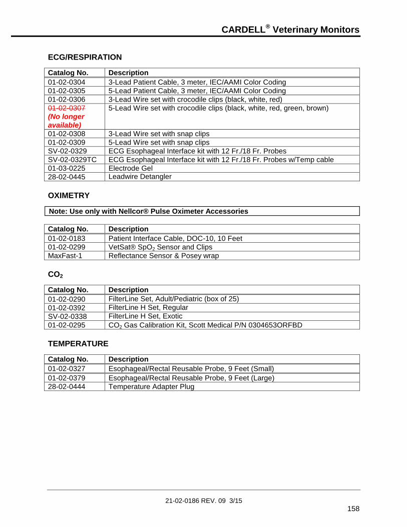
CARDELL® Veterinary Monitors
21-02-0186 REV. 09 3/15
158
ECG/RESPIRATION
Catalog No. Description
01-02-0304 3-Lead Patient Cable, 3 meter, IEC/AAMI Color Coding
01-02-0305 5-Lead Patient Cable, 3 meter, IEC/AAMI Color Coding
01-02-0306 3-Lead Wire set with crocodile clips (black, white, red)
01-02-0307
(No longer
available)
5-Lead Wire set with crocodile clips (black, white, red, green, brown)
01-02-0308 3-Lead Wire set with snap clips
01-02-0309 5-Lead Wire set with snap clips
SV-02-0329 ECG Esophageal Interface kit with 12 Fr./18 Fr. Probes
SV-02-0329TC ECG Esophageal Interface kit with 12 Fr./18 Fr. Probes w/Temp cable
01-03-0225 Electrode Gel
28-02-0445 Leadwire Detangler
OXIMETRY
Note: Use only with Nellcor® Pulse Oximeter Accessories
Catalog No. Description
01-02-0183 Patient Interface Cable, DOC-10, 10 Feet
01-02-0299 VetSat® SpO2 Sensor and Clips
MaxFast-1 Reflectance Sensor & Posey wrap
CO2
Catalog No. Description
01-02-0290 FilterLine Set, Adult/Pediatric (box of 25)
01-02-0392 FilterLine H Set, Regular
SV-02-0338 FilterLine H Set, Exotic
01-02-0295 CO2 Gas Calibration Kit, Scott Medical P/N 0304653ORFBD
TEMPERATURE
Catalog No. Description
01-02-0327 Esophageal/Rectal Reusable Probe, 9 Feet (Small)
01-02-0379 Esophageal/Rectal Reusable Probe, 9 Feet (Large)
28-02-0444 Temperature Adapter Plug

CARDELL® Veterinary Monitors
21-02-0186 REV. 09 3/15
159
OTHER ACCESSORIES
Catalog No. Description
01-02-0395 Replacement Power Cord, U.S.A.
01-02-0386 Replacement Power Cord, European
01-02-0385 Replacement Power Cord, Australian
01-02-0384 Replacement Power Cord, U.K.
03-08-0450 Monitor Battery Pack (7.2 VDC, 3700 mAhr)
01-01-0047 P9 Calibration Kit (includes T - connector with tubing and male luer plug)
01-02-0248 500 ml Fixed Volume Cylinder
01-02-0172G Roll Stand with Basket
01-02-0269 Carry Bag
01-02-0189 Printer, includes Battery, RS232 Cable, Power Supply, One (1) Roll of Paper and Manual
01-02-0181 Printer Bracket Attachment for Roll Stand
01-02-0300
(No longer
available)
Printer Mount Attachment for Monitor
28-02-0077 Printer Paper, One (1) Roll 01-02-0266 Printer Power Supply Adapter Plug, European 01-02-0267 Printer Power Supply Adapter Plug, UK 01-02-0268 Printer Power Supply Adapter Plug, Australian
01-03-0162 Cardell NIBP Inflation Hose, Six (6) Feet
01-03-0239 Equine NIBP Inflation Hose, Ten (10) Feet
09-01-0002 Fuse (250V, 500mA, 5x20 mm, Slow Blow), 2 per monitor
09-01-0034 Fuse (250V, 1.25A, 5x20 mm, Slow Blow), 2 per monitor
21-02-0186 Cardell Monitors Model 9403, 9404 and 9405 User’s Manual
MONITOR CONFIGURATIONS
Table 15: Monitor Configurations
Model Description
9403 ECG, Respiration and Temperature, MAXNIBP®, and Nellcor® Veterinary SpO2, 100-240V, 50/60HZ, AC Power Supply and Battery
9404 ECG, Respiration and Temperature and MAXNIBP®, 100-240V, 50/60HZ, AC Power Supply and Battery
9405 ECG, Respiration and Temperature, MAXNIBP®, Nellcor® Veterinary SpO2, and Oridion CO2, 100-240V, 50/60HZ, AC Power Supply and Battery

CARDELL® Veterinary Monitors
21-02-0186 REV. 09 3/15
160
This page is intentionally left blank

CARDELL® Veterinary Monitors
21-02-0186 REV. 09 3/15
161
15. SPECIFICATIONS ECG
Characteristic Specification
Input: 3 or 5 leads
Selectable Leads: I, II, III, aVL, aVR, aVF, V
Gain: X.5, X1, X2, X4, X8, X16, Automatic
Display Sweep Speeds: 12.5, 25, 50 mm/Sec
QRS Tone Volume: User-selectable: 5 settings, Off
Frequency Response: 0.5 to 25 Hz
Sensitivity Adjustment: Automatic
Minimum Signal: 0.20 mV peak-to-peak
Common Mode Rejection: >90dB
Loose Lead Threshold: 2.0 to 2.5 K ohms
Pacemaker Spike Rejection: Meets AAMI Standards
HEART RATE
Characteristic Specification
Asystole Detection: 4 seconds
Alarms: User-selectable: low heart rate and high heart rate
Alarm Delay Time: 5 seconds
Numeric Resolution: 1 BPM
Accuracy: +/- 3 BPM or +/- 3%, whichever is greater
Numeric Range: 0, 15 to 300 BPM averaged, 1 second update

CARDELL® Veterinary Monitors
21-02-0186 REV. 09 3/15
162
RESPIRATION
Characteristic Specification
Detection Technique: Impedance Pneumography
Sensing Electrodes: LA-RA
Bandwidth: 0.05 to 2.5 Hz
Sweep Speed: 3, 6.25, 12.5 mm/Sec
Sense Frequency: 63 kHz
Sensitivity Adjustment: Automatic
Trigger Level: Minimum trigger at 0.20 ohm.
Respiration Rate Numeric: 0 to 150 BrPM averaged, 1 second update
Accuracy: 0 to 122 BrPM +/- 1 BrPM 123 to 150 BrPM +/- 2 BrPM
Numeric Resolution: 1 BrPM
Alarms: User-selectable: low and high respiration rate
Base Impedance Range: 0 to 3.5 K ohms at 63 kHz
NIBP MEASUREMENT
Characteristic Specification
Technique: Oscillometric (MAXNIBP® Technology) Microprocessor software eliminates most ambient noise and motion artifact.
Blood Pressure Range
Systolic: 25 to 265 mmHg
Diastolic: 15 to 220 mmHg
MAP: 20 to 235 mmHg
Pulse Rate Range: 20 to 300 BPM
Accuracy
Blood Pressure: +/-5 mmHg with a standard deviation no greater than 8 mmHg (See Standards)
Pulse Rate: +/-2% or +/-2 BPM, whichever is greater

CARDELL® Veterinary Monitors
21-02-0186 REV. 09 3/15
163
%SpO2 MEASUREMENT
Characteristic Specification
Nellcor® OxiMax®
Type: Functional Oxygen Saturation
SpO2 % Range: 0 to 100%
SpO2 Accuracy: 70 to 100%, +/-2 digits (1 S.D.) Adult
70 to 100%, +/-3 digits (1 S.D.) Neonate
Measurement Wavelengths: Red 660 Nanometers
Infrared 890 Nanometers
Power: Not exceeding 15 mW
Pulse Rate Range: 20 to 300 BPM
Pulse Rate Accuracy: +/-3 digits
Numerics: Updated every one (1) second.
NOTE: Accuracy is specified for adult human hemoglobin measured at the fingertip. Although animal hemoglobin has similar optical characteristics, other types of hemoglobin may affect the accuracy.
TEMPERATURE
Characteristic Specification
Input: YSI® 400 compatible
Temperature Range: 28 to 43 °C (82.4 to 109.4 °F)
Accuracy: +/-0.1°C (+/-0.2°F)
Resolution: 0.1°C or 0.1°F

CARDELL® Veterinary Monitors
21-02-0186 REV. 09 3/15
164
CAPNOGRAPHY
Characteristic Specification
Oridion MicroStream®
Units: mmHg
Sampling Rate: 50 ml/min. +/- 7.5 ml/min.
CO2 Range: 0 to 99 mmHg (0 to 13.2 kPa and 0 to 13.0 vol% at sea level)
Accuracy: 0 to 38 mmHg +/- 2 mmHg 39 to 99 mmHg +/- 5% of reading +0.08% for every 1 mmHg (above 38 mmHg).
Equivalent values for kPa and vol%
Respiration Rate: 0 to 150 breaths/min.
Resolution: 1 mmHg
Initialization Time: 30 seconds (typical)
Frequency Response: EtCO2 accuracy is maintained up to 80 breaths/min. (For maintaining accuracy for respiration rate over 60 bpm, use the neonatal mode.) From 81 to 150 bpm accuracy is +/-12%, if the EtCO2 is higher than 18.8 mmHg in neonatal mode.
System Response Time: 2.9 seconds typical, (includes the delay time and the rise time)
Rise Time: Adult and Neonate: 190 msec max.
Delay Time: 2.7 seconds typical.
Ambient Pressure: Compensated internally – automatic
PATIENT ALARMS
Characteristic Specification
Adjustable Alarms: High and low alarms for Heart Rate, %SpO2, Pulse Rate, EtCO2, Respiration Rate, Systolic and Diastolic Pressure and MAP. High alarms for FiCO2; Low alarms for No Respiration
Fixed Alarms: Asystole
Alarm History: 25 most recent alarms
Indicators: Audible, Yellow Equipment Alarm LED’s, Red Patient Alarm LED’s, and Text in Patient Message Window

CARDELL® Veterinary Monitors
21-02-0186 REV. 09 3/15
165
9403
Patient Parameters
Low Limit High Limit
HR: 25 to 295 BPM 25 to 295 BPM
RR: 5 to 145 BrPM 5 to 145 BrPM
No RESP: 10 to 60 Sec
% SpO2: 70 to 95 % 80 to 99 %
SatSeconds: 10 to 100
SYS: 30 to 260 mmHg 30 to 260 mmHg
DIA: 20 to 215 mmHg 20 to 215 mmHg
MAP: 25 to 230 mmHg 25 to 230 mmHg
9404
Patient Parameters
Low Limit High Limit
HR: 25 to 295 BPM 25 to 295 BPM
RR: 5 to 145 BrPM 5 to 145 BrPM
No RESP: 10 to 60 Sec
SYS: 30 to 260 mmHg 30 to 260 mmHg
DIA: 20 to 215 mmHg 20 to 215 mmHg
MAP: 25 to 230 mmHg 25 to 230 mmHg
9405
Patient Parameters
Low Limit High Limit
HR: 25 to 295 BPM 25 to 295 BPM
% SpO2: 70 to 95 % 80 to 99 %
SatSeconds: 10 to 100
EtCO2: 1 to 99 mmHg 1 to 99 mmHg
FiCO2: 3 to 30 mmHg
RR: 5 to 145 BrPM 5 to 145 BrPM
No RESP: 10 to 60 Sec
SYS: 30 to 260 mmHg 30 to 260 mmHg
DIA: 20 to 215 mmHg 20 to 215 mmHg
MAP: 25 to 230 mmHg 25 to 230 mmHg
NOTE: Each alarm limit may also be selected “OFF” individually or as a whole. Low Limits cannot be set above the associated High Limit. High Limits cannot be set lower than the associated Low Limit.

CARDELL® Veterinary Monitors
21-02-0186 REV. 09 3/15
166
CONTROL PANEL
Characteristic Specification
Display: LCD display of measurement results, instructions, troubleshooting messages, waveforms and signal strength bar.
Parameters Displayed: Systolic Pressure, Diastolic Pressure and Mean Arterial Pressure (MAP) or Systolic Pressure, Diastolic Pressure and Pulse Rate
Heart Rate
Respiration Rate
%SpO2
Pulse Rate
EtCO2 (mmHg)
Temperature (in Fahrenheit or Celsius)
OPERATING MODES
Characteristic Specification
Patient: Veterinary
ECG: Continuous Monitoring
NIBP: Manual, STAT or Automatic (at preset intervals)
History: Trend: Review of previous measurements
Alarm: Review of previous alarms
%SpO2: Continuous Monitoring
CO2 Continuous Monitoring
Temperature: Continuous Monitoring
POWER
Characteristic Specification
Source: External line or internal battery
AC Power Option: 100 - 240 VAC, 50/60 Hz, 0.5A; Fuse Rating – T500mAL250V or T1.25AL250V (two provided). Refer to rear panel monitor labeling for actual fuse rating.
Battery: Nickel Metal Hydride (NiMH) battery pack (user removable)
Charge Time: 3 - 5 hours
Operation on battery: Approximately four (4) hours.
Leakage Current: 100 microamp (maximum)

CARDELL® Veterinary Monitors
21-02-0186 REV. 09 3/15
167
FEATURES
Characteristic Specification
Self Test: System self test is performed each time power is turned on.
Auto Zero: Zero pressure reference is automatically established after every reading.
Inflation: Initial inflation to 150 mmHg or user selectable (Adaptive, 80, 100, 120, 140, 150, 160, 180, 200). Subsequent inflation to approximately 30 mmHg greater than previous Systolic pressure.
Deflation: Automatic
Max Measurement Time: Limited to 150 seconds
SAFETY LIMITS
Characteristic Specification
Automatic Cuff Deflation: If cuff pressure exceeds 290 mmHg
If measurement time exceeds 150 seconds
If safety timer detects microprocessor failure
OPERATING ENVIRONMENT
Characteristic Specification
Operating Temperature: 0°C to 50°C (32°F to 122°F)
Humidity: 15 - 95%, non-condensing
Altitude: 10,000 to –1,250 ft (700 – 1050 hPa)
Monitors may not meet performance specifications if stored or used outside temperature and humidity ranges. When moving the monitor from a storage location, wait at least one-hour prior to use to allow the monitor to adjust to room temperature.

CARDELL® Veterinary Monitors
21-02-0186 REV. 09 3/15
168
STORAGE/TRANSPORT ENVIRONMENT
Characteristic Specification
Storage / Transport Temperature:
-20°C to 65°C (-4°F to 149°F)
Humidity: 15 - 95%, non-condensing
Altitude: 10,000 to –1,250 ft (700 – 1050 hPa)
PHYSICAL DIMENSIONS & WEIGHT
Characteristic Specification
Base Unit
H x W x D: 6.75 in x 8.5 in x 4.0 in
(17 cm x 21.5 cm x 10.2 cm)
Weight: 4.1 lbs approx. (1.4 kg)
SERIAL INTERFACE
Characteristic Specification
Interface: Bidirectional serial communication
Speed: 9600 for Printer 115200 for CAS Serial Protocol
Signal Level: RS232C
Data Length: 8 bits
Start Bit: 1 bit
Stop Bit: 1 bit
Parity: None
Flow Control: None

CARDELL® Veterinary Monitors
21-02-0186 REV. 09 3/15
169
STANDARDS Units comply with the following requirements:
IEC 60601-1 EN 60601-1-2 IEC 60601-2-30 EN 60601-2-49 EN 865 UL Classified - UL 2601-1, CAN/CSA C22.2 No.601.1. If so marked
CARDELL® is a registered trademark of Midmark.
, , Tuff-Cuff®, Safe-Cuff®, SoftCheck®, UltraCheck® and “FOR WHAT’S VITAL” are registered trademarks of CAS Medical Systems, Inc.
Microstream® and FilterLine® are registered trademarks of Oridion Medical 1987 LTD.
Nellcor®, VetSat® and OxiMax® are registered trademarks of Mallinckrodt Inc. SatSeconds™ is a trademark of Mallinckrodt, Inc.
Velcro® is a registered trademark of Velcro USA, Inc.
YSI® is a registered trademark of Yellow Springs Instrument Company
All units covered by U.S. patent 4,796,184 and 5,022,403. Other patents pending.
Monitors are if so marked.

CARDELL® Veterinary Monitors
21-02-0186 REV. 09 3/15
170
This page is intentionally left blank

CARDELL® Veterinary Monitors
21-02-0186 REV. 09 3/15
171
16. APPENDIX
DEAD SPACE - Cause, Effect, & Control in Small Animal Anesthesia
Robert M. Stein, D.V.M.. DAAPM
Founder www.VASG.org
Dead space is an often misunderstood and overlooked aspect of veterinary anesthesia patient management. Dead space is always present as a component of the patient’s airway and, to a variable degree, as a component of the anesthetic system. Ignoring the harmful consequences of system dead space can lead to potentially fatal patient outcomes. This is especially worrisome when managing small patients. There are three different types of dead space: anatomic, alveolar, and mechanical (equipment). Dead space ventilation involves that component of the respiratory gases that does not participate in gas exchange. Simply said, there is no patient benefit from dead space ventilation. If mechanical dead space volume equals or exceeds alveolar ventilation volume the patient will not be able to clear carbon dioxide at all. Ideally, your goal should be to minimize dead space through proper patient planning and to detect excess dead space consequences through end-tidal CO2 monitoring.
Anatomic dead space is comprised of the upper airway structures that do not participate in gas exchange. This includes the gases in the nasal passages, nasopharynx, larynx, trachea, and in
the larger airways. Alveolar dead space represents those alveoli that are ventilated with fresh
gas but not perfused by the pulmonary circulation. Mechanical or equipment dead space is made up of any portion of the endotracheal tube extending beyond the patient’s incisors, patient monitor adaptors (ETCO2, apnea alert, etc.), any adaptors used to facilitate patient/system positioning (right-angle or swivel adaptors used to reduce the risk of tracheal trauma during patient rotation), the pace within a mask not occupied by the patient’s nose, humidification management exchangers (HME), and the “Y” piece (defined as the terminal end of an F circuit or noncircle system and the inhalation/exhalation hose connector in a circle system). Exhausted soda lime or malfunctioning one-way valves can also contribute to increasing mechanical dead space. Dead space also increases in a non-rebreathing system when fresh gas flows are inadequate or when certain defects are present in the system (for instance, when the center tube of a Bain system or F circuit is cracked or broken). These dead space contributors can all be controlled through proper system inspection and maintenance. Mechanical dead space gas is the first gas inhaled at the beginning of the each respiratory
cycle. As the mechanical dead space volume increases, less fresh gas moves into the patient’s alveoli, limiting gas exchange.
Anesthetic System
Norman Elbow Jackson-Rees Bain Ped circle Adult circle Adult F Ped F
Dead space <1 ml 3 ml 4 ml 4 ml 8 ml 8 ml 15 ml
Adaptors
ET tube Monitor - ped Monitor - adult Positional Heat & Moisture Exchanger (HME)
Dead Space 2 ml 2 ml 7 ml 8 ml 2.5 to 90 ml

CARDELL® Veterinary Monitors
21-02-0186 REV. 09 3/15
172
The consequences of excessive mechanical dead space can be substantial and,
potentially, fatal. As dead space volume from any cause increases, effective alveolar ventilation decreases. In patients breathing 100% oxygen there may be negligible initial effect on arterial oxygen tension. Arterial CO2, however, can reach impressive levels. It is possible to have an end-tidal CO2 level greater than 110 mmHg in patients with a normal pulse oximeter reading.
Increased arterial CO2 causes: o Respiratory acidosis o Sympathetic stimulation o Cardiac arrhythmias
A mix of sympathetic stimulation and hypoxemic effects o Variable peripheral vasoconstriction (sympathetic effect) followed by peripheral
vasodilation as a direct effect on peripheral vessels o CNS depressant effect and, eventually narcosis
PaCO2 levels above 100 mmHg have an anesthetic effect o Increased cerebral blood flow and intracranial pressure o Tachypnea and an increased work of breathing which can negatively impact a
debilitated patient
Arterial O2 levels may eventually decrease enough to cause hypoxemia, especially in a patient breathing room air
Inadequate ventilation interferes with adjustments in anesthetic levels
Controlling mechanical dead space is a simple matter.
Mechanical dead space is most concerning for patients under 6 kg body weight o Minimize the connectors attached to the endotracheal tube, particularly in small
patients. For example, in a 6 kg patient under anesthesia the patient’s alveolar
ventilation volume would be 31.5 ml. Using a pediatric F circuit with adult ETCO2 monitor and right angle adaptor (or apnea alert adaptor) could create 30 ml of mechanical dead space; effectively eliminating 95% of normal spontaneous alveolar ventilation.
Make sure you regularly inspect all anesthetic machines and systems paying particular attention to valve function and inner hose integrity
Make sure that the ET tube is not excessively long
Select your anesthetic system carefully
o Do not use a pediatric F circuit as a substitute for conventional pediatric circle hoses or a noncircle system
Using no more than one monitor adaptor o Make sure it is a pediatric, low volume adaptor for smaller patients to avoid any
significant impact on total mechanical dead space
Avoid the use of positional (right angle) adaptors in smaller patients
Avoid maintaining anesthesia with a facemask Simply put, anesthetized patients should have their end-tidal CO2 monitored for maximal patient safety.

CARDELL® Veterinary Monitors
21-02-0186 REV. 09 3/15
173
17. PURCHASING RECORD CARDELL VITAL SIGNS MONITOR
Installed Options: ECG/Resp & Temp ( ) SpO2 ( )
NIBP ( ) CO2 ( )
Model: 9403 ( ) 9404 ( ) 9405 ( )
Serial Number:
Date of Purchase:
Distributor Name:
Representative:
Phone Number:
Fax Number:
Email: