captain jack mill superfund site pre-design investigation
TRANSCRIPT

1
CAPTAIN JACK MILL SUPERFUND SITE
Pre-Design Investigation and Subsurface Remedy
Design ConceptCraig Weber, P.E., AMEC E&IAbby Bazin, P.E., AMEC E&IBruce Wielinga, PhD, AMEC E&I

2
Acknowledgements
Colorado Department of Public Health and Environment – Mary Boardman
U.S. Environmental Protection Agency, Region 8 – Joy Jenkins
Key Partners Zonge International RAS, Inc. Multi-Phase Technologies, LLC James Drilling Flatirons Surveying, Inc. Agapito Associates, Inc. McCollum Excavating

3
Presentation Overview
Technical and Regulatory Background for Captain Jack Site Pre-Design Activities and Findings
Subsurface Remedy Schematic Design Flow-through Bulkhead Mine Pool Treatment Long-term Monitoring
4
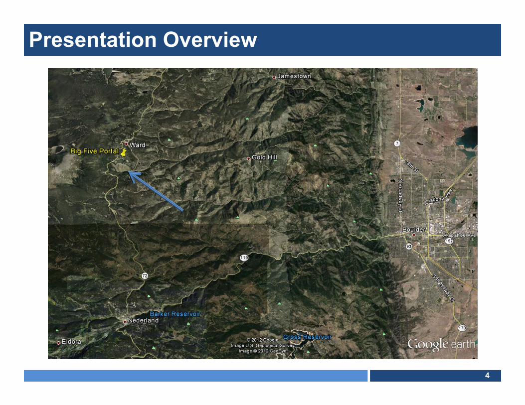
Site Location
Presentation Overview
5
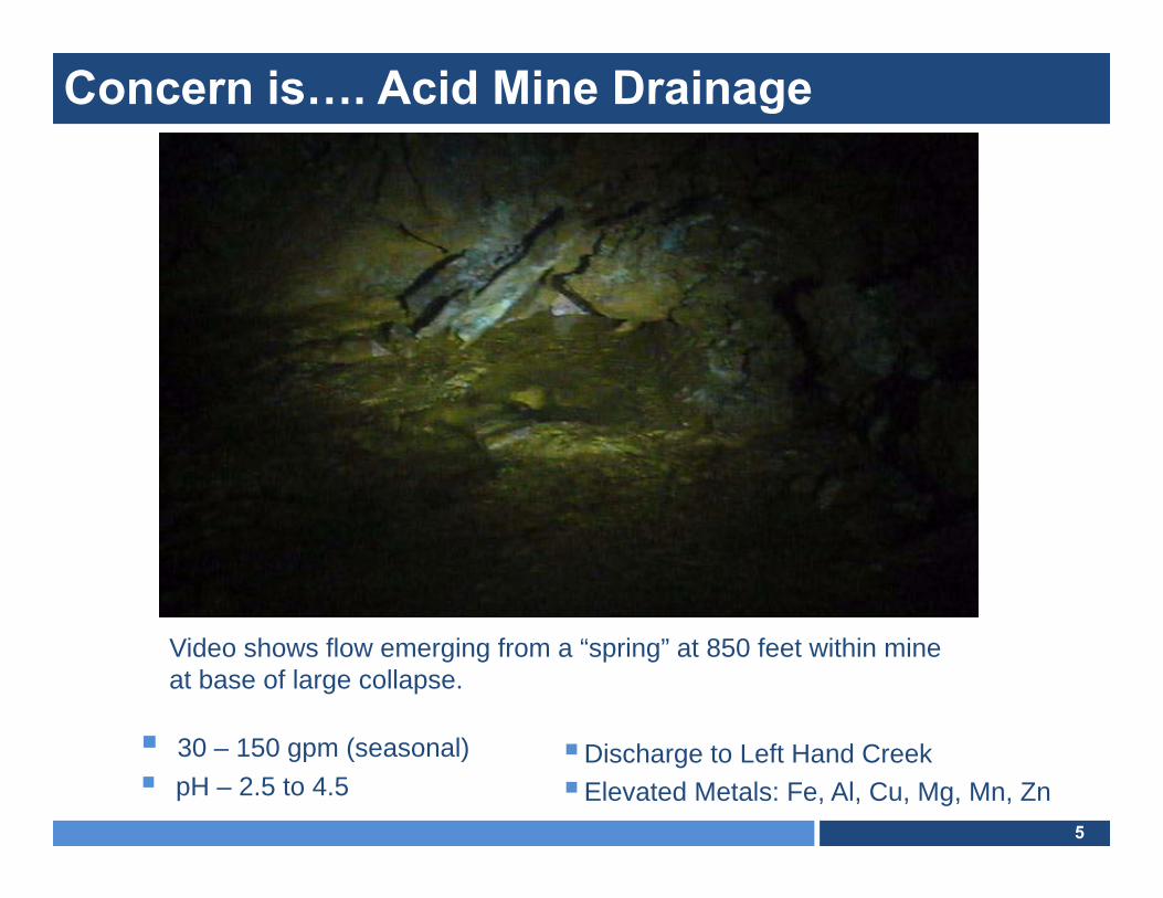
Concern is…. Acid Mine Drainage
30 – 150 gpm (seasonal) pH – 2.5 to 4.5
Video shows flow emerging from a “spring” at 850 feet within mine at base of large collapse.
Discharge to Left Hand CreekElevated Metals: Fe, Al, Cu, Mg, Mn, Zn
6
Mining and Milling Operations from 1890’s to 1992
Listed on National Priority List (NPL) by USEPA in September 2003 due to Heavy Metals Loading to Left Hand Creek Watershed
Colorado State Lead
ROD Signed in September 2008 by EPA and CDPHE
Remedial Effort Divided into Two Actions: 1) Surface Cleanup2) Subsurface Remedy
AMEC E&I Selected for Subsurface Remedy Remedial Design in February 2011
Regulatory Summary
7
Alternative 3B from the RI/FS A bulkhead with stainless steel through-piping and valves
Mine-pool mitigation anticipated to include a neutralization loop with an injection and extraction well drilled into the tunnel reservoir
Operational monitoring
Treatment Concept Treats mine water “in-situ”
Submerges source materials (to the extent safely practicable) in order to minimize contact with oxygen
Implement active neutralization of impounded mine-pool waters
If needed, a second phase of remedial operations will include an ex-situ bioreactor
Selected Remedy in the ROD

8
8,800 feet amsl
Site Characteristics
9
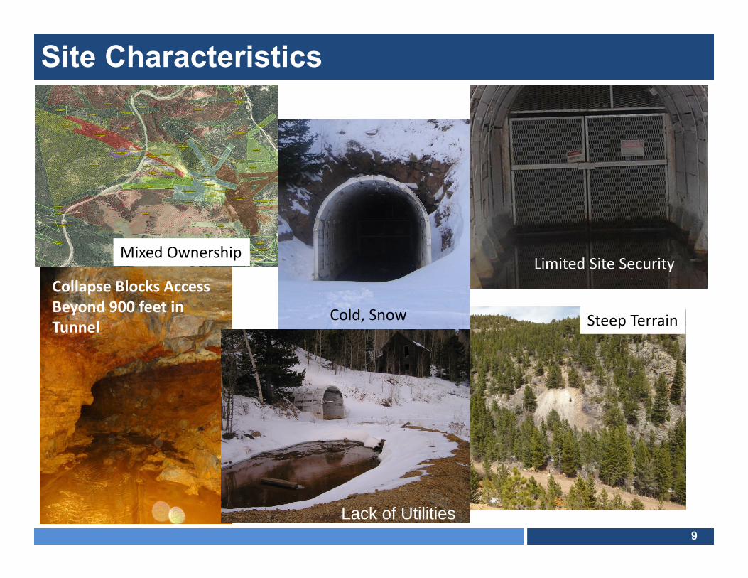
Site Characteristics
Collapse Blocks Access Beyond 900 feet in Tunnel
Limited Site Security
Steep Terrain
Mixed Ownership
Cold, Snow
Lack of Utilities
10
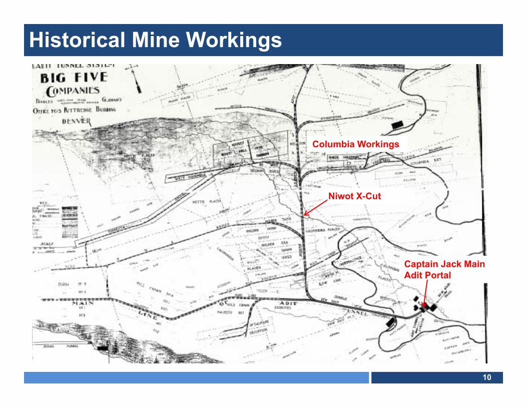
Historical Mine Workings
Columbia Workings
Niwot X-Cut
Captain Jack Main Adit Portal

11
Historical Mine Workings
Portal
Niwot X-Cut
Columbia Vein
Dew Drop Workings

12
Dew Drop Workings
Connection to Big Five?
250 feet above Big Five and parallel
Dew Drop Mine
Dew Drop Portal
13
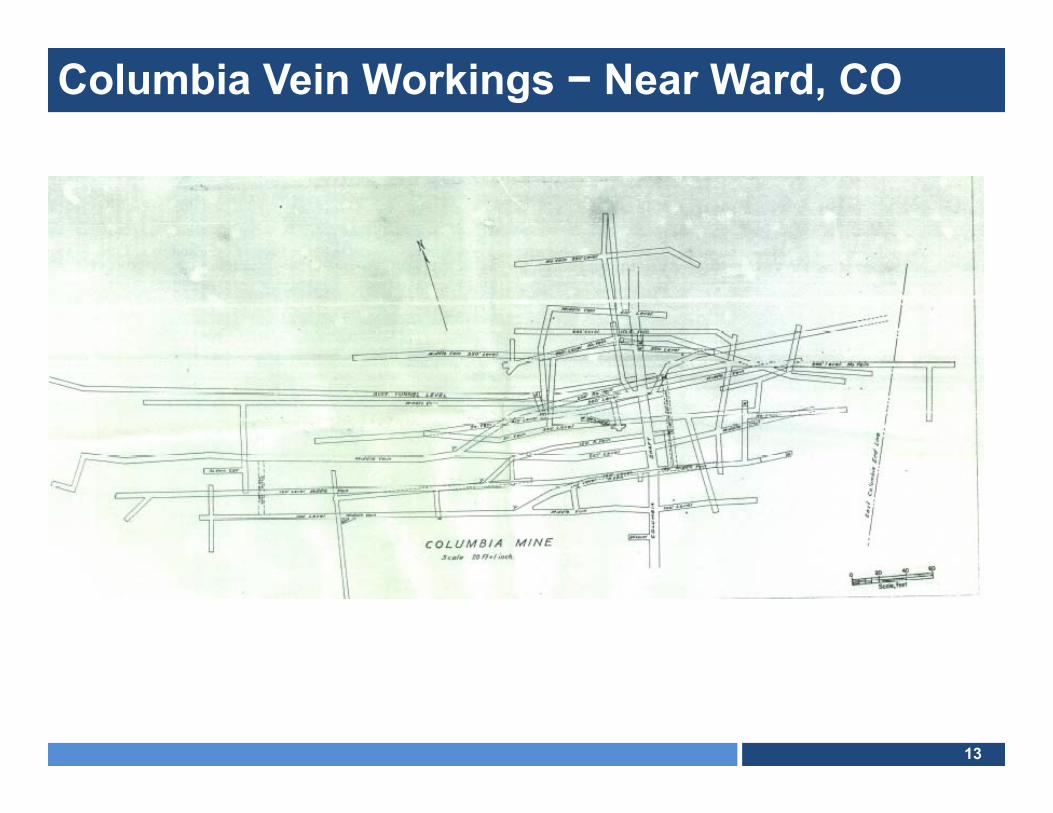
Columbia Vein Workings − Near Ward, CO
14
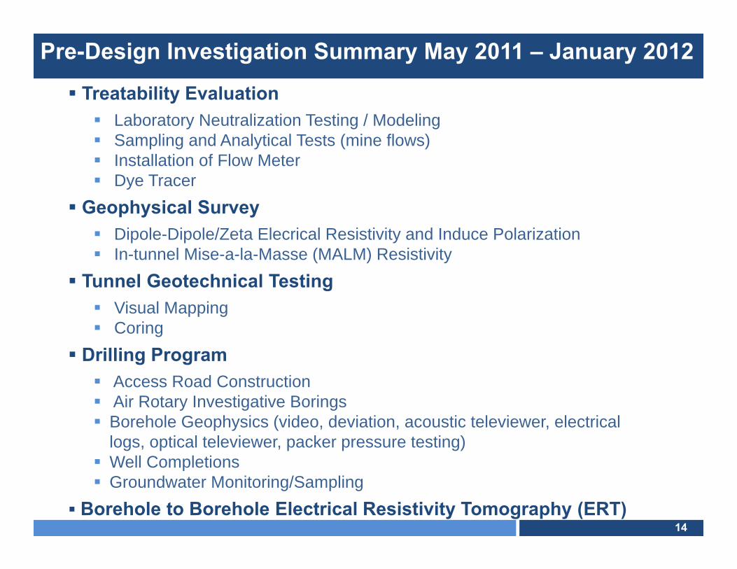
Pre-Design Investigation Summary May 2011 – January 2012
Treatability Evaluation Laboratory Neutralization Testing / Modeling Sampling and Analytical Tests (mine flows) Installation of Flow Meter Dye Tracer
Geophysical Survey Dipole-Dipole/Zeta Elecrical Resistivity and Induce Polarization In-tunnel Mise-a-la-Masse (MALM) Resistivity
Tunnel Geotechnical Testing Visual Mapping Coring
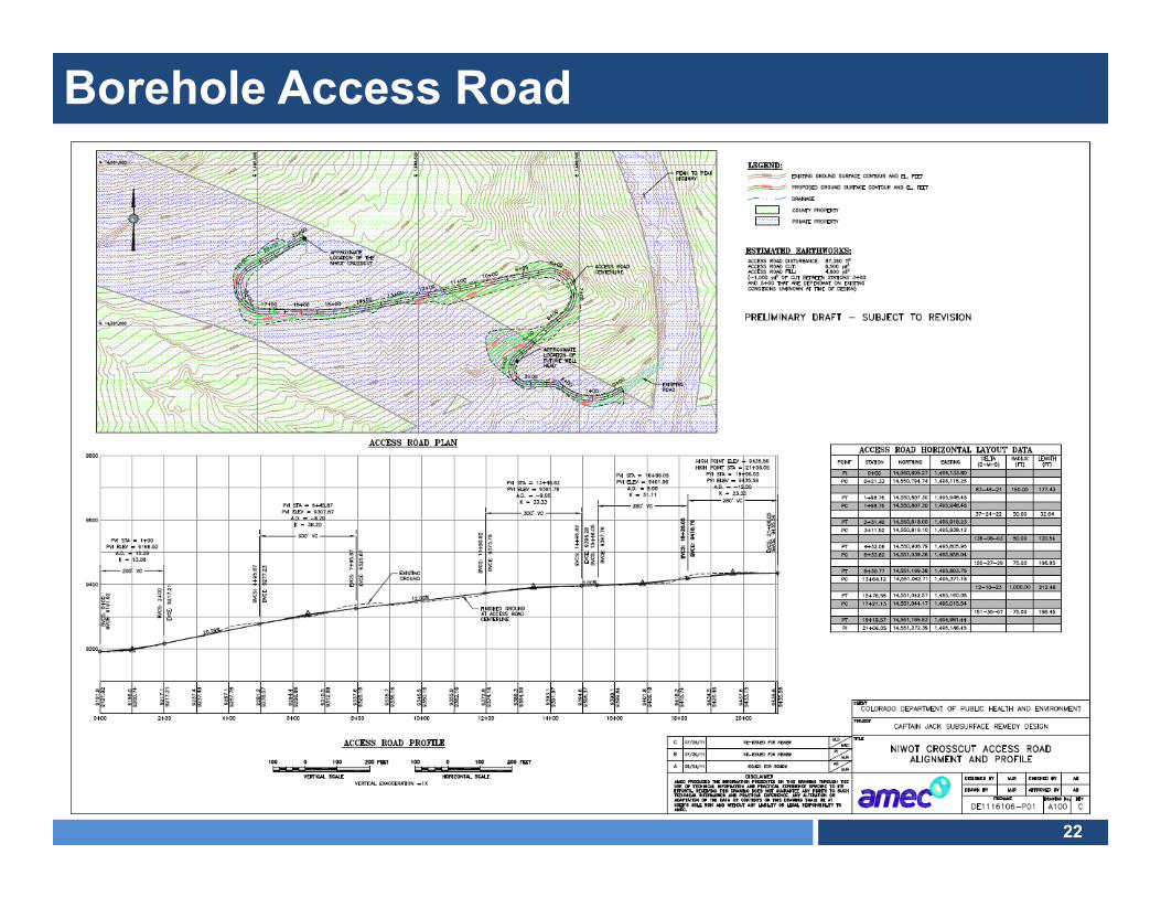
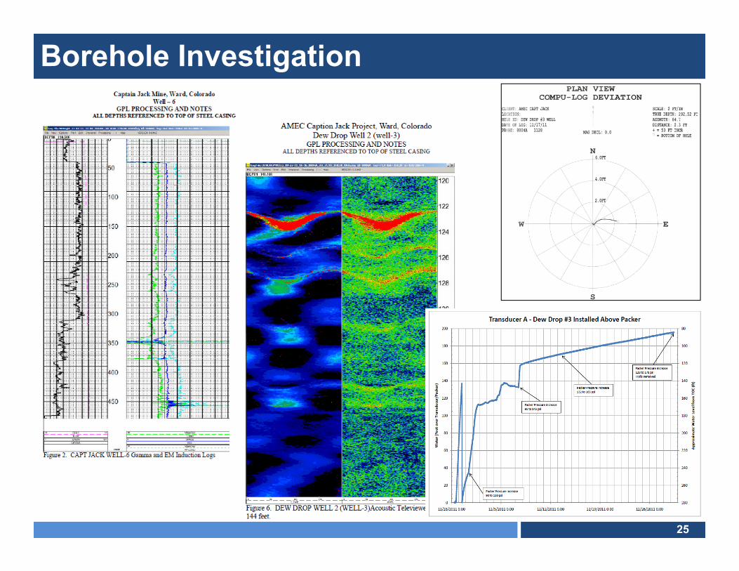
Drilling Program Access Road Construction Air Rotary Investigative Borings Borehole Geophysics (video, deviation, acoustic televiewer, electrical
logs, optical televiewer, packer pressure testing) Well Completions Groundwater Monitoring/Sampling
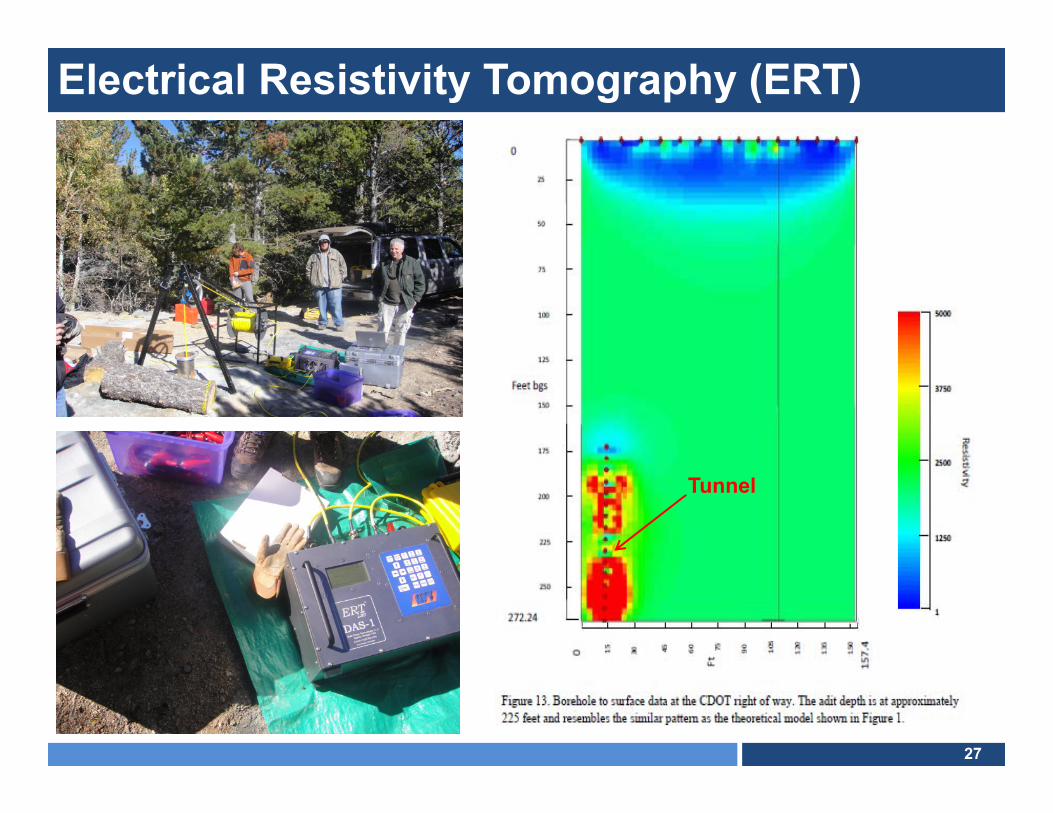
Borehole to Borehole Electrical Resistivity Tomography (ERT)

15
Treatability Data
0.0
0.1
0.2
0.3
0.4
0.5
0.6
0.7
0.8
0.9
0
0.1
0.2
0.3
0.4
0.5
0.6
2.5 3.5 4.5 5.5 6.5 7.5 8.5 9.5 10.5 11.5 12.5
NaO
H (m
L/L)Ca(O
H) 2
(g/L
)
pH
LimeLime TestsCausticCaustic Tests
0.0
0.2
0.4
0.6
0.8
1.0
7.5 8.0 8.5 9.0 9.5
Zinc
(mg/
L)
pH
Ca(OH)2 - Dissolved
Ca(OH)2 - Total
NaOH - Dissolved
NaOH - Total
Captain Jack AMD as Collected
Metals scan
Analysis by AGAT Laboratories
Analysis by TestAmerica
Dissolved Total
Dissolved Total
mg/L mg/L mg/L mg/LAluminum (Al) 13 13 13 13Cadmium (Cd) 0.015 0.015 0.015 0.016Calcium (Ca) 161 162 - 150Cobalt (Co) 0.13 0.13 - -Copper (Cu) 8 8.4 7.8 8.0Iron (Fe) 23 48 40 51Magnesium (Mg) 81 81 - 86Manganese (Mn) 9.7 9.8 9.2 9.5Nickel (Ni) 0.14 0.14 0.14 0.14Sodium (Na) 7 7 - -Sulfur (S) 335 338 - -Zinc (Zn) 3.3 3.4 2.6 2.9Sulfates (SO4) 10051 10141 - 14002
Note 1 Sulfate concentration reported was calculated based on S analysis (ICP) by AGAT Laboratory
Note 2 Sulfate concentration reported was analyzed by ion chromatography at TestAmerica Laboratory
Test Conditions
Alkali Consumption Solids ProductionCa(OH)2 NaOH Ca(OH)2 NaOH
(g/L) (ml/L) (g/L)
pH 7.5 0.195 0.271 0.196 0.196
pH 8.0 0.205 0.279 0.174 0.200
pH 8.5 0.215 0.282 0.173 0.220
pH 9.0 0.233 0.289 0.215 0.215
pH 9.5 0.247 0.296 0.204 0.220

16
AMD Evaluations
Sample Collection at 800 feet
Flow Velocity Logger
One of Several Seeps
Flow Meter Installed

17
Geophysics – Locate Mine Workings
Transmitting Electrode Connected to Rails in Dew Drop Mine

18
Geophysics − MALM Summary

19
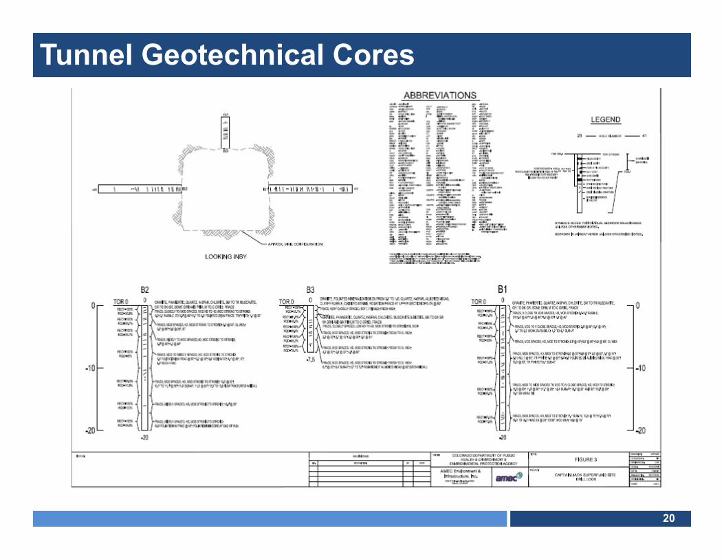
Mine Tunnel Geotechnical Testing
Proposed Bulkhead
Portal
20
Tunnel Geotechnical Cores

21
Geotechnical Work
Pneumatic Core Drill
Hydraulic Pressure Test
22
Borehole Access Road

23
Drilling Effort
Dew Drop Wells
Air Rotary Rig (James Drilling)
Road Rough Cut (McCollum Excavating)

24
Drilling Summary
25
Borehole Investigation

26
Borehole Logging
27
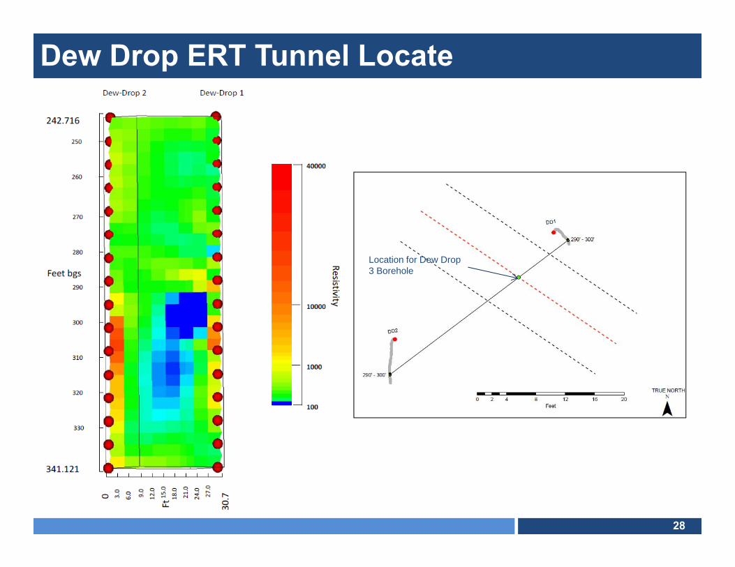
Electrical Resistivity Tomography (ERT)
Tunnel
28
Dew Drop ERT Tunnel Locate
Location for Dew Drop 3 Borehole
29
Dew Drop 3 Video in Mine
30
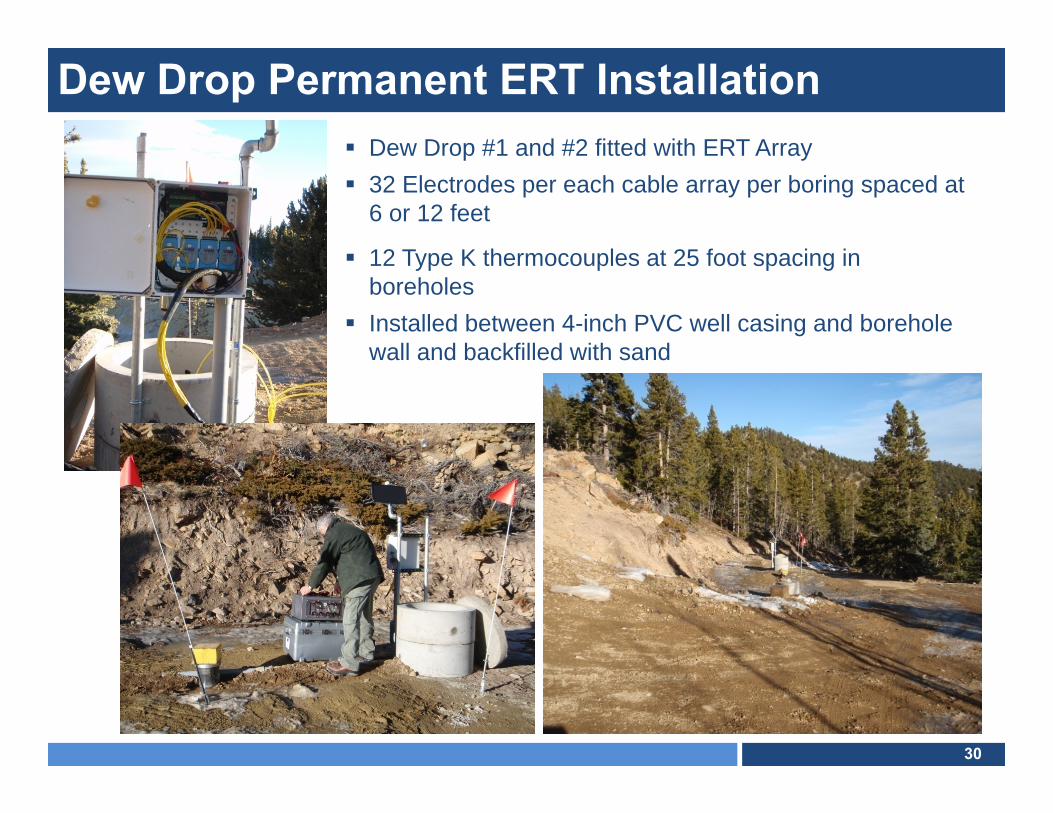
Dew Drop Permanent ERT Installation Dew Drop #1 and #2 fitted with ERT Array 32 Electrodes per each cable array per boring spaced at
6 or 12 feet
12 Type K thermocouples at 25 foot spacing in boreholes
Installed between 4-inch PVC well casing and borehole wall and backfilled with sand

31
Consolidated Plan View

32
Plan and Profile
33
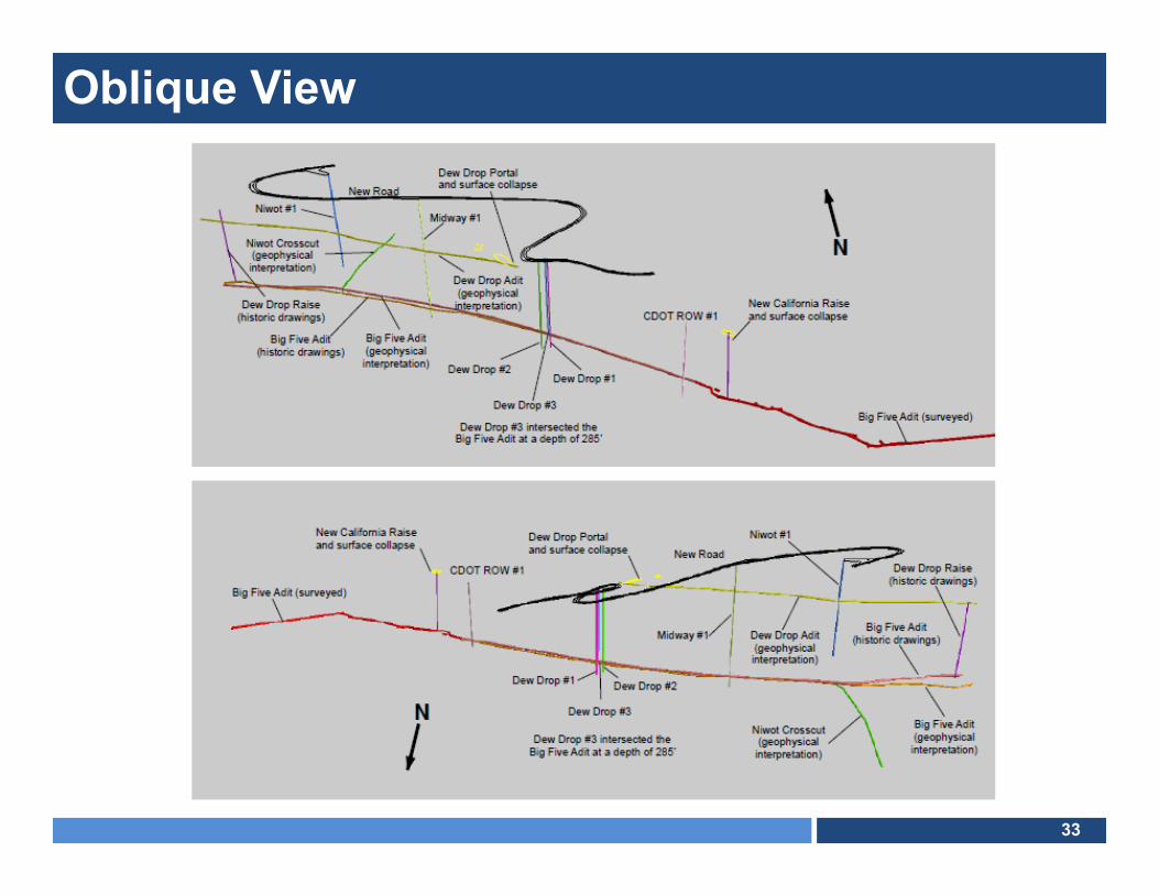
Oblique View

34
Remedy Concept
35
Key Engineering Objectives
Plug Big Five Mine Tunnel to Flood Mine Workings and Eliminate Portal Discharge
Treat Portion of Resulting Mine Pool In-Situ to Raise pH and Precipitate Metals
Minimize Long-Term Operating and Maintenance Costs of Treatment
Monitor Mine Pool Development and Water Quality; and Surrounding Surface and Subsurface Conditions
Minimize Costs of Long-term Monitoring with Remote Data Acquisition

36
Data Gaps and AssumptionsDATA GAPS:
Condition of Mine Beyond 900 Feet Extent of Connected Mine Workings (Volume) Main Source of AMD (Columbia vein via Niwot X- cut??) Mine Pool Leakage Rate vs. Pressure Increase Equilibrium Pressure Potential to “flood” workings on Columbia Vein near Ward
ASSUMPTIONS:
Current Assumption: 1,000 feet of tunnel = 710,000 gallons Bulkhead will leak treated water suitable for discharge to creek New pathways for surface leaks (springs) would likely manifest
east of Hwy. 72 where pressure is greatest and distance to surface is shortest

37
Concrete “Mass” Bulkhead

38
Recirculation Alternative − Short
39
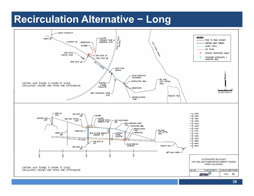
Recirculation Alternative − Long

40
“Passive” Limestone Bed

41
In−Situ Sulfate Reducing Bioreactor

42
Autonomous Long Term Monitoring - ERT

43
Long-Term Monitoring – Automated Samplers

44
Power Supply Line Power – Not available on site; 2,500 feet to nearest
potential source Generator – Long term maintenance; fuel storage; fuel
resupplyWind – Erratic in this vicinity Solar – Good potential pending power demand
Estimate 3 Kw/hr max. (as needed, intermittent) Estimate 500 ft2 of PV panel – direct connect
(no battery storage)
