canonical ordering for triangulations on the cylinder ... · canonical ordering for triangulations...
TRANSCRIPT

HAL Id: hal-00705181https://hal.inria.fr/hal-00705181
Submitted on 7 Jun 2012
HAL is a multi-disciplinary open accessarchive for the deposit and dissemination of sci-entific research documents, whether they are pub-lished or not. The documents may come fromteaching and research institutions in France orabroad, or from public or private research centers.
L’archive ouverte pluridisciplinaire HAL, estdestinée au dépôt et à la diffusion de documentsscientifiques de niveau recherche, publiés ou non,émanant des établissements d’enseignement et derecherche français ou étrangers, des laboratoirespublics ou privés.
Canonical ordering for triangulations on the cylinder,with applications to periodic straight-line drawings
Luca Castelli Aleardi, Olivier Devillers, Eric Fusy
To cite this version:Luca Castelli Aleardi, Olivier Devillers, Eric Fusy. Canonical ordering for triangulations on the cylin-der, with applications to periodic straight-line drawings. [Research Report] RR-7989, INRIA. 2012.<hal-00705181>

ISS
N0
24
9-6
39
9IS
RN
INR
IA/R
R--
79
89
--F
R+
EN
G
RESEARCHREPORT
N° 7989June 2012
Project-Team Geometrica
Canonical ordering fortriangulations on thecylinder, withapplications to periodicstraight-line drawingsLuca Castelli Aleardi, Olivier Devillers, Éric Fusy

RESEARCH CENTRE
SOPHIA ANTIPOLIS – MÉDITERRANÉE
2004 route des Lucioles - BP 93
06902 Sophia Antipolis Cedex
Canonical ordering for triangulations on the
cylinder, with applications to periodic
straight-line drawings
Luca Castelli Aleardi∗, Olivier Devillers†, Éric Fusy∗
Project-Team Geometrica
Research Report n° 7989 — June 2012 — 12 pages
Abstract: We extend the notion of canonical orderings to cylindric triangulations. This allowsus to extend the incremental straight-line drawing algorithm of de Fraysseix et al. to this setting.Our algorithm yields in linear time a crossing-free straight-line drawing of a cylindric triangulationT with n vertices on a regular grid Z/wZ × [0, h], with w ≤ 2n and h ≤ n(2d + 1), where d isthe (graph-) distance between the two boundaries. As a by-product, we can also obtain in lineartime a crossing-free straight-line drawing of a toroidal triangulation with n vertices on a periodicregular grid Z/wZ×Z/hZ, with w ≤ 2n and h ≤ 1+ n(2c+1), where c is the length of a shortestnon-contractible cycle. Since c ≤
√2n, the grid area is O(n5/2).
Key-words: triangulations, graph drawing, flat torus
This work is partially supported by ERC under the agreement ERC StG 208471 - ExploreMap.
∗ LIX, École Polytechnique, France† Projet Geometrica, INRIA Sophia-Antipolis, France

Ordre canonique pour des triangulations du cylindre et
applications au tracé linéaire de graphes périodiques
Résumé : Nous étendons la notion d’ordre canonique à des triangulations cylindriques.L’algorithme incrémental de tracé de graphe planaire introduit par de Fraysseix et al. peutainsi être étendu au cas cylindrique. Notre algorithme permet d’obtenir en temps linéaire untracé linéaire sans croisement d’une triangulation cylindrique T avec n sommets sur la grillerégulière Z/wZ× [0, h], où w ≤ 2n et h ≤ n(2d+ 1), avec d la distance (en nobre d’arètes de latriangulation) entre les deux bords. On peut en déduire un algorithme en temps linéaire pour untracé linéaire sans croisement d’une triangulation du tore sur la grille périodique Z/wZ×Z/hZ,où w ≤ 2n et h ≤ 1+n(2c+1), avec c la longueur du plus court cycle non contractible. Commec ≤√2n, l’aire de la grille est en O(n5/2).
Mots-clés : triangulations, tracé de graphe, tore plat

Periodic straight-line drawings 3
1 Introduction
The problem of efficiently computing straight-line drawings of planar graphs has attracted alot of attention over the last two decades. Two combinatorial concepts for planar triangula-tions turn out to be the basis of many classical straight-line drawing algorithms: the canonicalordering (a special ordering of the vertices obtained by a shelling procedure) and the closelyrelated Schnyder wood (a partition of the inner edges of a triangulations into 3 spanning treeswith specific incidence conditions). Algorithms based on canonical ordering [7, 10] are typicallyincremental, adding vertices one by one while keeping the drawing planar. Algorithms based onSchnyder woods [14] are more global, the (barycentric) coordinates of each vertex have a clearcombinatorial meaning (typically the number of faces in certain regions associated to the vertex).Algorithms of both types make it possible to draw in linear time a planar triangulation with nvertices on a grid of size O(n × n). They can also both be extended to obtain (weakly) convexdrawings of 3-connected maps on a grid of size O(n × n). The problem of obtaining planardrawings of higher genus graphs has been addressed less frequently [11, 9, 12, 13, 4, 6, 15], fromboth the theoretical and algorithmic point of view. Recently some methods for the straight-lineplanar drawing of genus g graphs with polynomial grid area have been described in [4, 6] (toapply these methods the graph needs to be unfolded planarly along a cut-graph). However itdoes not yield (at least easily) periodic representations: for example, in the case of a torus, theboundary vertices (on the boundary of the rectangular polygon) might not be aligned, so thatthe drawing does not give rise to a periodic tiling.
Our main contribution is to generalize the notion of canonical ordering and the incrementalstraight-line drawing algorithm of de Fraysseix et al [7] to triangulations on the cylinder. Theobtained straight-line drawing of a cylindric triangulation T with n vertices is x-periodic, on aregular grid of the form Z/wZ× [0, h], with w ≤ 2n and h ≤ n(2d+ 1), where d is the (graph-)distance between the two boundaries. By a reduction to the cylindric case (the reduction isdone with the help of a so-called tambourine [2]), we can also obtain a straight-line drawing of atoroidal triangulation T with n vertices on a grid Z/wZ×Z/hZ, with w ≤ 2n and h ≤ 1+n(2c−1),where c is the length of a shortest non-contractible cycle. Since c ≤ (2n)1/2 as shown in [1], wehave h ≤ (2n)3/2, so that the grid area is O(n5/2).
For the toroidal case we mention that a notion of canonical ordering has been introducedin [5] (this actually works in any genus and yields an efficient encoding procedure) but we donot use it here. We also mention that, independently, an elegant periodic straight-line drawingalgorithm for toroidal triangulations has been very recently described in [8], based on so-calledtoroidal Schnyder woods and face-counting operations; in their case the area of the periodic gridis O(n4).
2 Preliminaries
Graphs embedded on surfaces. A map of genus g is a graph (cellularly) embedded on theclosed surface of genus g. The map is called planar for g = 0 (embedding on the sphere) andtoroidal for g = 1 (embedding on the torus). The dual of a map G is the map G∗ representingthe adjacencies of the faces of G, i.e., there is a vertex vf of G∗ in each face f of G, and eachedge e of G gives rise to an edge e∗ in G∗: if f and f ′ are the faces on each side of e then e∗
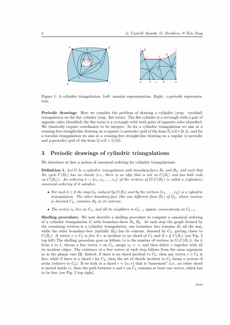
connects vf to vf ′ . A cylindric map is a planar map with two marked faces B1 and B2 whoseboundaries C(B1) and C(B2) are simple cycles (possibly C(B1) and C(B2) share vertices andedges). The faces B1 and B2 are called the boundary-faces. Boundary vertices and edges arethose belonging to C(B1) (black circles in Fig. 1) or C(B2); (red circles in Fig. 1) the other onesare called inner vertices (white circles in Fig. 1) and edges.
RR n° 7989
4 L. Castelli Aleardi, O. Devillers, & Éric Fusy
b adcab
a d
c
e
ki jh
g
f
e
ki j
h
g
f
Figure 1: A cylindric triangulation. Left: annular representation. Right: x-periodic representa-tion.
Periodic drawings Here we consider the problem of drawing a cylindric (resp. toroidal)triangulation on the flat cylinder (resp. flat torus). The flat cylinder is a rectangle with a pair ofopposite sides identified; the flat torus is a rectangle with both pairs of opposite sides identified.We classically require coordinates to be integers. So for a cylindric triangulation we aim at acrossing-free straight-line drawing on a regular (x-periodic) grid of the form Z/wZ×[0, h], and fora toroidal triangulation we aim at a crossing-free straight-line drawing on a regular (x-periodicand y-periodic) grid of the form Z/wZ× Z/hZ.
3 Periodic drawings of cylindric triangulations
We introduce at first a notion of canonical ordering for cylindric triangulations:
Definition 1. Let G be a cylindric triangulation with boundary-faces B1 and B2, and such thatthe cycle C(B1) has no chords (i.e., there is no edge that is not on C(B1) and has both endson C(B1)). An ordering π = {v1, v2, . . . , vn} of the vertices of G\C(B1) is called a (cylindric)canonical ordering if it satisfies:
• For each k ≥ 0 the map Gk induced by C(B1) and by the vertices {v1, . . . , vk} is a cylindrictriangulation. The other boundary-face (the one different from B1) of Gk, whose contouris denoted Ck, contains B2 in its interior.
• The vertex vk lies on Ck, and all its neighbors in Gk−1 appear consecutively on Ck−1.
Shelling procedure. We now describe a shelling procedure to compute a canonical orderingof a cylindric triangulation G with boundary-faces B1, B2. At each step the graph formed bythe remaining vertices is a cylindric triangulation, one boundary face remains B1 all the way,while the other boundary-face (initially B2) has its contour, denoted by Ck, getting closer toC(B1). A vertex v ∈ Ck is free if v is incident to no chord of Ck and if v /∈ C(B1) (see Fig. 2top left).The shelling procedure goes as follows (n is the number of vertices in G\C(B1)): for kfrom n to 1, choose a free vertex v on Ck, assign vk ← v, and then delete v together with allits incident edges. The existence of a free vertex at each step follows from the same argumentas in the planar case [3]. Indeed, if there is no chord incident to Ck, then any vertex v ∈ Ck isfree, while if there is a chord e for Ck, then the set of chords incident to Ck forms a system ofarchs (relative to Ck). If we look at a chord e = {u, v} that is “innermost” (i.e., no other chordis nested inside e), then the path between u and v on Ck contains at least one vertex, which hasto be free (see Fig. 2 top right).
Inria
Periodic straight-line drawings 5
7
6
54
32
1
7
6
54
32
7
6
54
3
7
6
54
7
6
5
7
6
7
B1
B2
v C6
C7
v
e
v
w2
w1w1
w1 w1
F
F ∗
edge of F
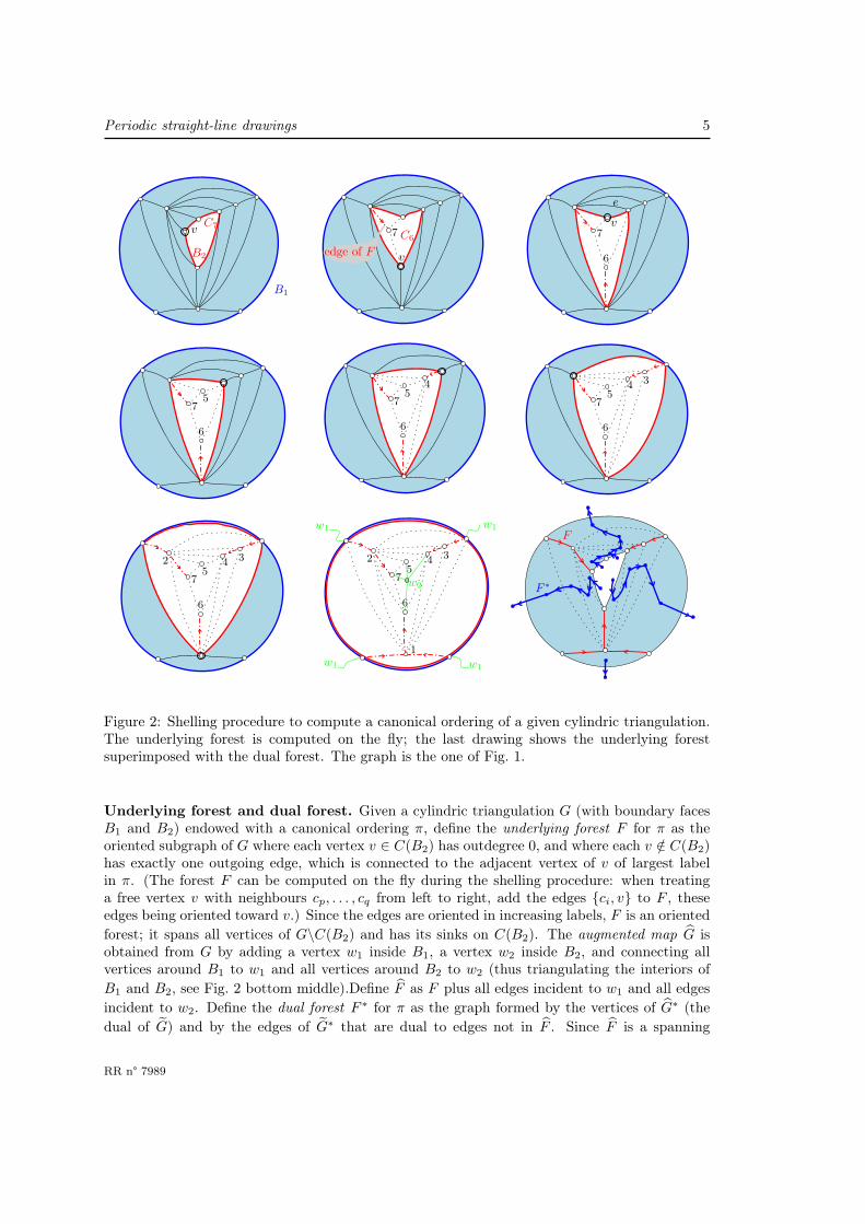
Figure 2: Shelling procedure to compute a canonical ordering of a given cylindric triangulation.The underlying forest is computed on the fly; the last drawing shows the underlying forestsuperimposed with the dual forest. The graph is the one of Fig. 1.
Underlying forest and dual forest. Given a cylindric triangulation G (with boundary facesB1 and B2) endowed with a canonical ordering π, define the underlying forest F for π as theoriented subgraph of G where each vertex v ∈ C(B2) has outdegree 0, and where each v /∈ C(B2)has exactly one outgoing edge, which is connected to the adjacent vertex of v of largest labelin π. (The forest F can be computed on the fly during the shelling procedure: when treatinga free vertex v with neighbours cp, . . . , cq from left to right, add the edges {ci, v} to F , theseedges being oriented toward v.) Since the edges are oriented in increasing labels, F is an oriented
forest; it spans all vertices of G\C(B2) and has its sinks on C(B2). The augmented map G isobtained from G by adding a vertex w1 inside B1, a vertex w2 inside B2, and connecting allvertices around B1 to w1 and all vertices around B2 to w2 (thus triangulating the interiors of
B1 and B2, see Fig. 2 bottom middle).Define F as F plus all edges incident to w1 and all edges
incident to w2. Define the dual forest F ∗ for π as the graph formed by the vertices of G∗ (the
dual of G) and by the edges of G∗ that are dual to edges not in F . Since F is a spanning
RR n° 7989

6 L. Castelli Aleardi, O. Devillers, & Éric Fusy
PℓPr
cpcq
ereℓ
Figure 3: One step of the incremental drawing algorithm. Two vertical strips of width 1 (eachone along a path in the dual forest) are inserted in order to make the slopes of eℓ and er smallerthan 1 in absolute value. Then the new vertex and its edges connected to the upper boundarycan be drawn in a planar way.
connected subgraph of G, F ∗ is a spanning tree of G∗. Precisely each of the trees (connectedcomponents) of F ∗ is naturally rooted at a vertex “in front of” each edge of B1, and the edgesof the tree can naturally be oriented toward this root-vertex (see Fig. 2 bottom right).
Drawing algorithm. Given a cylindric triangulation G with no chordal edge incident to B1,we first compute a canonical ordering of G, and then draw G in an incremental way. We startwith a cylinder of width 2|C(B1)| and height 0 (i.e., a circle of length 2|C(B1)|) and draw thevertices of C(B1) equally spaced on the circle (space 2 between two consecutive vertices). Thenthe strategy is —for each k ≥ 1— to compute the drawing of Gk out of the drawing of Gk−1 byfirst stretching the cylinder (increasing the width by 2) and then placing the vertex vk and itsincident edges (in Gk) in a planar way. Define the x-span of an edge e in the cylindric drawingas the number of columns [i, i+ 1]× [0,+∞] that meet the interior of e (we have no need for amore complicated definition since, in our drawings, a column will never meet an edge more thanonce).
Consider the dual forest F ∗ for the canonical ordering restricted to Gk−1. Let cp, cp+1, . . . , cqbe the path of Ck−1 such that Ck−1 is on the left of the path taking from cp to cq. Let eℓ be theedge {cp, cp+1} and er be the edge {cq−1, cq} (note that eℓ = er if q − p = 1). Let Pℓ (resp. Pr)be the path in F ∗ from e∗ℓ (resp. e∗r) to the root in its connected component (which is a vertex “infront of” an edge of B1)). We stretch the cylinder by inserting a vertical strip of length 1 alongPℓ and another along Pr (see Fig. 3). The effect is exactly to increase by 1 the x-span of eachedge dual to an edge in Pℓ, and then to increase by 1 the x-span of each edge dual to an edge inPr (note that Pℓ and Pr are not necessarily disjoint, in which case the x-span of an edge dual toan edge in Pℓ∩Pr is increased by 2, see Fig. 7 second on line3).After these stretching operations,whose effect is to make the slopes of eℓ and er strictly smaller than 1 in absolute value, we insert(as in the planar case) the vertex vk at the intersection of the ray of slope 1 starting from cp andthe ray of slope −1 starting from cq, and we connect vk to cp, . . . , cq by segments 1. These two
1In the de Fraysseix et al algorithm for planar triangulations, the step to make the (absolute value of) slopes ofeℓ and er smaller than 1 is formulated as a shift of certain subgraphs described in terms of the underlying forest F .The extension of this formulation to the cylinder would be quite cumbersome. We find the alternative formulationas strip insertions more convenient for the cylinder (it also gives rise to a very easy linear implementation).
Inria

Periodic straight-line drawings 7
1 1
2
1
2
3
1
2
3
4
1
2
3
45
1
2
3
4
5
1
2
3
4
5
6 6
54
3
1
2
12
3
45
6
7
1 1
2
1
2
3
1
2
3
4
Figure 4: Algorithm (Prop. 2) to compute an x-periodic drawing of a cylindric triangulation (nochordal edges incident to C0). The vertices are treated in increasing label (the canonical orderingis the one computed in Fig. 2).
rays actually intersects at a grid point since the Manhattan distance between any two verticeson Ck−1 is even.Fig. 7 shows the execution of the algorithm on the example of Fig. 1.
Proposition 2. For each cylindric triangulation G with no chordal edges incident to C(B1), onecan compute in linear time a crossing-free straight-line drawing of G on an x-periodic regulargrid Z/wZ× [0, h] where —with n the number of vertices of G and d the (graph-)distance betweenthe two boundaries— w = 2n and h ≤ n(2d + 1), such that: every v ∈ C(B1) has y(v) = 0 (soevery edge in C(B1) has slope 0), and every edge belonging to C(B2)\C(B1) has slope ±1.
Proof. The fact that the drawing remains crossing-free relies on the slope-property for the upperboundary and on the following inductive property that is easily shown to be maintained at eachstep k from 1 to n:
Pl: for each edge e on Ck (the upper boundary of Gk), let Pe
be the path in F ∗ from e∗ to the root, let Ee be the set of edgesdual to edges in Pe, and let δe be any positive integer. Then thedrawing remains planar when successively increasing by δe thex-span of all edges of Ee, for all e ∈ Ck\{a, b}.
We now prove the bounds on the grid-size. If |C(B1)| = t then the initial cylinder is 2t× 0;and at each vertex insertion, the grid-width grows by 2. Hence w = 2n. In addition, due to theslope conditions (slopes of boundary-edges are at most 1 in absolute value), the y-span (verticalspan) of every edge e is not larger than the current width at the time when e is inserted in thedrawing. Hence, if we denote by v the vertex of C(B2) that is closest (at distance d) to C(B1),
RR n° 7989

8 L. Castelli Aleardi, O. Devillers, & Éric Fusy
e2
e1
Figure 5: Drawing a cylindric triangulation with chords at B1. To make enough space to placethe component under e2, one takes 8 (instead of 2) as the initial x-span of e2.
then the ordinate of v is at most d · (2n). And due to the slope conditions, the vertical spanof C(B2) is at most w/2 ≤ n. Hence the grid-height is at most n(2d + 1). The linear-timecomplexity is shown next.
Linear-time implementation. An important remark is that, instead of computing the x-coordinates and y-coordinates of vertices in the drawing, one can compute the y-coordinates ofvertices and the x-span of edges (as well as the knowledge of which extremity is the left-end vertexand which extremity is the right-end vertex). In a first pass (for k from 1 to n) one computes they-coordinate of vertices and the x-span re of each edge e ∈ G at the time t = k when it appearson Gk (as well one gets to know which extremity of e is the left-end vertex). Afterward, and ife /∈ F , the x-span of e might further increase due to insertion of new vertices. Precisely let vjbe a vertex inserted afterwards (i.e., j > t), let cp, . . . , cq be its neighbours in Gj−1 from left toright, let eℓ = {cp, cp+1}, er = {cq−1, cq}, and let e′ℓ = {vj , cp} and e′r = {vj , cq}. Note that e isstretched due to the insertion of the strip along Pℓ iff either e = eℓ or eℓ is in the subtree of F ∗
formed by the edges descending from e∗. This happens iff e′ℓ is in the subtree Te of F ∗ formedby the edges descending from e∗. Similarly e is stretched due to the insertion of the strip alongPr iff e′r is in Te. To state it more clearly, each edge in Te is responsible for an increase (by 1)of the x-span of e. Hence the total x-span of each edge e ∈ G is given by re + se, where se = 0if e ∈ F , and, if e /∈ F , se is the number of edges in Te. Since all quantities se can easily becomputed in linear time, this gives a linear implementation.
Allowing for chordal edges at B1. We finally explain how to draw a cylindric triangulationwhen allowing for chordal edges incident to C0 = C(B1); it is good to view B2 as the topboundary-face and B1 as the bottom-boundary face (and imagine a standing cylinder). For eachchordal edge e of C0, the component under e is the face-connected part of G that lies below e;such a component is a quasi-triangulation (polygonal outer face, triangular inner faces) rootedat the edge e. A chordal edge e of C0 is maximal if the component Qe under e is not strictlyincluded in the component under another chordal edge. The size of such an edge e is defined as|e| = |V (Qe)| − 2. (the size |e| is actually the width of the drawing of Qe using the de Fraysseixet al algorithm [7]). If we delete the component under each maximal chordal edge (i.e., delete
Inria

Periodic straight-line drawings 9
everything from the component except for the chordal edge itself) we get a new bottom cycleC ′
0 that is chordless, so we can draw the reduced cylindric triangulation G′ using the algorithmof Proposition 2. As we have seen in Section 3 (linear implementation paragraph), for each edgee of C ′
0, the initial x-stretch is re = 2 and then the further increase se of the x-stretch equalsthe number of edges descending from e∗ in the dual forest F ∗. Note that we have actually somefreedom to choose the initial x-stretch re of each edge on e ∈ C ′
0 (just it has to be a positiveeven number, since at each step of the incremental algorithm the vertices of the current upperboundary have to be at even Manhattan distance). If e ∈ C0 (i.e., e was not chordal in G) wetake re = 2. If e /∈ C0 (i.e., e was a maximal chordal edge in G), we take for re the minimal evenpositive number such that re + se ≥ |e|, i.e., re = 2 ·max(1, ⌈(|e| − se)/2⌉). Hence, at the endof the execution of the drawing of G′, the length ℓe = re + se of each maximal chord e satisfiesℓe ≥ |e|. Then for each maximal chord e of C0, we draw the component Qe under e using theplanar algorithm by de Fraysseix et al [7]. this drawing has width |e|, with e as horizontal bottomedge of length |e| and with the other outer edges of slopes ±1. We shift the left-extremity of eso that the drawing of Qe gets width ℓ(e), then we rotate the drawing of Qe by 180 degrees andplug it into the drawing of G′ (see Fig. 5). The overall drawing of G thus obtained is clearlyplanar. We obtain:
Theorem 3. For each cylindric triangulation G, one can compute in linear time a crossing-freestraight-line drawing of G on an x-periodic regular grid Z/wZ× [0, h], where —with n the numberof vertices and d the (graph-) distance between the two boundaries— w ≤ 2n and h ≤ n(2d+ 1).The drawing is vertically convex (the intersection with each vertical line is a segment) and theslopes of boundary-edges are at most 1 in absolute value.
4 Periodic drawings of toroidal triangulations
For a toroidal triangulation G, a tambourine is a pair of parallel (i.e., homotopically equivalent)non-contractible oriented cycles Γ1 and Γ2 such that the edges arriving to Γ1 from the rightdepart at Γ2 and the edges arriving to Γ2 from the left depart at Γ1 It can be shown (see [2]and the next paragraph) that for each non-contractible cycle Γ of G, there exists a tambourinewhose two cycles are parallel to Γ. Deleting the edges that are strictly inside the tambourine,one obtains a cylindric triangulation G′ with Γ1 and Γ2 as the contours of the boundary-faces.Note also that the distance d between Γ1 and Γ2 is smaller than the length of a shortest non-contractible cycle not parallel to Γ. We now apply the algorithm of Theorem 3 to G′. If augmentthe height h of the drawing to h′ = h+w+1, and then wrap the x-periodic grid Z/wZ×[0, h] intoa periodic grid Z/wZ×Z/h′
Z, and finally insert the edges inside the tambourine as segments 2,then the slope properties (edges on Γ1 and Γ2 have slope at most 1 in absolute value while edgesinside the tambourine have slope greater than 1 in absolute value) ensure that the resultingdrawing is crossing-free (see Fig. 6).
An important remark is that we can choose Γ so that the graph-distance between the twoboundaries Γ1 and Γ2 (in G′) is smaller that the length γ of a shortest non-contractible cycle inG; and this choice for Γ can be done without computing a shortest non-contractible cycle. Let{Γa,Γb} be a basis of non-contractible cycles (which can be found in linear time by computingfor instance a cut-graph). Denoting by Γmin a shortest non-contractible cycle of G, for sure atleast one of Γa or Γb is not parallel to Γmin. Hence, for Γa or for Γb, the distance between theboundary-cycles (after deleting edges of the parallel tambourine) is smaller than |Γmin|. In other
2We insert the edges in the tambourine T in the unique way such that, looking from bottom to top, at leastone edge in T goes strictly to the right, and all edges going strictly to the right have x-span at most w; in thisway it is easy to check that the x-span of all edges in T is at most w.
RR n° 7989

10 L. Castelli Aleardi, O. Devillers, & Éric Fusy
cb da cb da
ab
cd a
ab
cd
a b c d
d
e
ea
e
e
Figure 6: The main steps for drawing of a toroidal triangulation : 1) remove the edges inside atambourine, (2) draw the obtained cylindric triangulation, 3) insert the edges of the tambourineback into the drawing.
words if we choose the one cycle (among {Γa,Γb}) that yields the smaller distance between thetwo boundaries of G′, then this distance will be smaller than γ. We obtain:
Theorem 4. For each toroidal triangulation G, one can compute in linear time a crossing-freestraight-line drawing of G on a periodic regular grid Z/wZ× Z/hZ, where —with n the numberof vertices and γ the length of a shortest non-contractible cycle— w ≤ 2n and h ≤ 1+n(2γ+1).Since γ ≤
√2n (as shown in [1]), the grid area is O(n5/2).
Existence of a tambourine. For the sake of completeness we include a proof of existence of atambourine, which slightly extends the proof given in the master’s thesis of Arnaud Labourel. Atoroidal map is called weakly 3-connected if its periodic representation in the plane is 3-connected.Let G be such a map and let Γ be a non-contractible cycle of G. We are going to show that Ghas a tambourine parallel to Γ. Let G′ be the cylindric map obtained after cutting G along Γ;we take the annular representation of G′, calling Γ1 (resp. Γ2) the copy of Γ that is the outer(resp. inner) boundary. Let Γ′ be the smallest (in terms of the enclosed area) cycle that strictlyencloses Γ2 (i.e., encloses Γ2 and is vertex-disjoint from Γ2). Let Γ′′ be the largest (in terms ofthe enclosed area) cycle that is strictly enclosed in Γ′ (i.e., is enclosed by Γ′ and is vertex-disjointfrom Γ′). Note that by minimality Γ′ has no chord inside, and by maximality Γ′′ has no chordoutside. Hence if we can show that there is no vertex in the area A (strictly) between Γ′ andΓ′′ then we can conclude that, in G, Γ′ and Γ′′ form a tambourine parallel to Γ. Assume thereis a vertex v in A. Call vertex of attachment for Γ′ a vertex w such that there is a path fromv to w visiting only vertices of A before reaching w. Again by minimality of Γ′ it is easy to seethat there is a unique vertex of attachment v′ for Γ′. Similarly (by maximality of Γ′′) there is aunique vertex of attachment v′′ for Γ′′. Let Γv be the connected component of G′\{v′, v′′} that
Inria
Periodic straight-line drawings 11
2 2
1
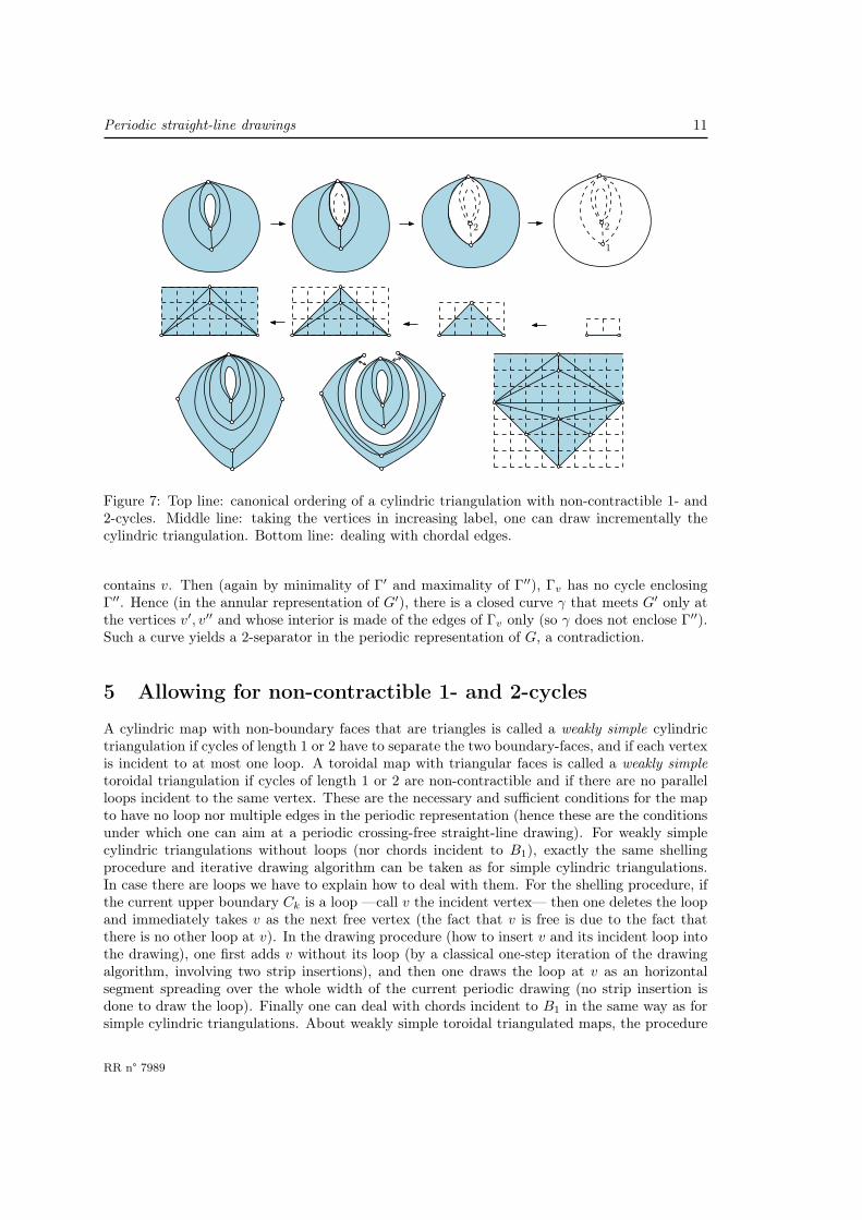
Figure 7: Top line: canonical ordering of a cylindric triangulation with non-contractible 1- and2-cycles. Middle line: taking the vertices in increasing label, one can draw incrementally thecylindric triangulation. Bottom line: dealing with chordal edges.
contains v. Then (again by minimality of Γ′ and maximality of Γ′′), Γv has no cycle enclosingΓ′′. Hence (in the annular representation of G′), there is a closed curve γ that meets G′ only atthe vertices v′, v′′ and whose interior is made of the edges of Γv only (so γ does not enclose Γ′′).Such a curve yields a 2-separator in the periodic representation of G, a contradiction.
5 Allowing for non-contractible 1- and 2-cycles
A cylindric map with non-boundary faces that are triangles is called a weakly simple cylindrictriangulation if cycles of length 1 or 2 have to separate the two boundary-faces, and if each vertexis incident to at most one loop. A toroidal map with triangular faces is called a weakly simpletoroidal triangulation if cycles of length 1 or 2 are non-contractible and if there are no parallelloops incident to the same vertex. These are the necessary and sufficient conditions for the mapto have no loop nor multiple edges in the periodic representation (hence these are the conditionsunder which one can aim at a periodic crossing-free straight-line drawing). For weakly simplecylindric triangulations without loops (nor chords incident to B1), exactly the same shellingprocedure and iterative drawing algorithm can be taken as for simple cylindric triangulations.In case there are loops we have to explain how to deal with them. For the shelling procedure, ifthe current upper boundary Ck is a loop —call v the incident vertex— then one deletes the loopand immediately takes v as the next free vertex (the fact that v is free is due to the fact thatthere is no other loop at v). In the drawing procedure (how to insert v and its incident loop intothe drawing), one first adds v without its loop (by a classical one-step iteration of the drawingalgorithm, involving two strip insertions), and then one draws the loop at v as an horizontalsegment spreading over the whole width of the current periodic drawing (no strip insertion isdone to draw the loop). Finally one can deal with chords incident to B1 in the same way as forsimple cylindric triangulations. About weakly simple toroidal triangulated maps, the procedure
RR n° 7989

12 L. Castelli Aleardi, O. Devillers, & Éric Fusy
is also the same as for simple toroidal triangulations, since the above proof of existence of atambourine holds in that case. And the grid bounds (whether for the cylindre or for the torus)are the same as for simple triangulations.
AcknowledgmentsThe authors thank D. Gonçalves and B. Lévêque, and (independently) B. Mohar for interestingdiscussions about toroidal Schnyder woods, and N. Bonichon for explanations on the computationof a tambourine in a toroidal triangulation.
References
[1] M. O. Albertson and J. P. Hutchinson. On the independence ratio of a graph. J. Graph. Theory,2:1–8, 1978.
[2] N. Bonichon, C. Gavoille and A. Labourel. Edge partition of toroidal graphs into forests in lineartime. In ICGT, volume 22, pages 421–425, 2005.
[3] E. Brehm. 3-orientations and Schnyder 3-Tree decompositions. Master’s thesis, FUB, 2000.
[4] E. Chambers, D. Eppstein, M. Goodrich, M. Loffler. Drawing graphs in the plane with a prescribedouter face and polynomial area. In GD, pages 129–140, 2011.
[5] L. Castelli-Aleardi, E. Fusy, and T. Lewiner. Schnyder woods for higher genus triangulated surfaces,with applications to encoding. Discr. & Comp. Geom., 42(3):489–516, 2009.
[6] C. Duncan, M. Goodrich, S. Kobourov. Planar drawings of higher-genus graphs. Journal of Graph
Algorithms and Applications, 15:13–32, 2011.
[7] H. de Fraysseix, J. Pach and R. Pollack. How to draw a planar graph on a grid. Combinatorica,10(1):41–51, 1990.
[8] D. Gonçalves and B. Lévêque. Toroidal maps : Schnyder woods, orthogonal surfaces and straight-line representation. arXiv:1202.0911, 2012.
[9] S. J. Gortler, C. Gotsman and D. Thurston Discrete one-forms on meshes and applications to 3Dmesh parameterization. Computer Aided Geometric Design, 23 (2): 83–112, 2006.
[10] G. Kant. Drawing planar graphs using the canonical ordering. Algorithmica, 16(1):4–32, 1996.
[11] W. Kocay, D. Neilson and R. Szypowski. Drawing graphs on the torus. Ars Combinatoria, 59:259–277, 2001.
[12] B. Mohar. Straight-line representations of maps on the torus and other flat surfaces. Discrete
Mathematics, 15:173–181, 1996.
[13] B. Mohar and P. Rosenstiehl. Tessellation and visibility representations of maps on the torus.Discrete & Comput. Geom., 19:249–263, 1998.
[14] W. Schnyder. Embedding planar graphs on the grid. In SoDA, pages 138–148, 1990.
[15] A. Zitnik. Drawing graphs on surfaces. In SIAM J. Disc. Math, 7(4):593–597, 1994.
Inria

RESEARCH CENTRE
SOPHIA ANTIPOLIS – MÉDITERRANÉE
2004 route des Lucioles - BP 93
06902 Sophia Antipolis Cedex
Publisher
Inria
Domaine de Voluceau - Rocquencourt
BP 105 - 78153 Le Chesnay Cedex
inria.fr
ISSN 0249-6399