“call for participation” in high speed signaling metrology...
TRANSCRIPT

“Call for Participation” In
High Speed Signaling Metrology
andStandard Reliability
QualificationProject Formation
Session 1
Friday, March 14
10:00 am – 11:00 am EDT

iNEMI Connectors Interest Survey
Background
• iNEMI is exploring several electronic connector initiatives
recommended through discussions with leading OEMs and EMS
firms
• The purpose of these projects is to highlight, study, and develop
metrics on potential manufacturing challenges facing the industry's
use of certain connector types as we move forward
2

iNEMI Connectors Interest Survey
Background (Continued)
• High Speed Signaling Metrology: as circuit speeds and noise margins approach difficult parameters
Product Examples: Processor Sockets, Memory Sockets, Backplane Connectors, next generation IO Connectors
• Standard Reliability Qualification: Designed to provide predictive MTBFs or other reliability measures for mainstream products and applications
Product Examples: CPU Sockets, DDR4 Memory Sockets, Press-Fit Backplane Connectors, HDD and SSD Connectors, IO Connectors to 100Gbps
• Dynamic Warpage Measurements: Designed to test susceptible products with larger areas, thin/long LCP housings combined with SMT attach
Product Examples: DDR4 Memory Sockets, Processor Sockets > 2,000 Pins
3

iNEMI Connectors Interest SurveyBackground (Continued)
• Key Challenges for Press-Fit Connectors: Designed for high speed applications with short pins - or automotive apps desiring press-fit assembly
Product Examples: Backplane Connectors, Automotive Connectors with short pins
• State of Art Memory Connectors: Designed for future DRAM applications beyond DDR4
Product Examples: Memory Connector surpassing DDR4 requirements > 5Gt/s range
• Emerging Special Needs Automotive Connectors: Perhaps focusing on EV/PHEV electric vehicle HV/motor control interconnects
Product Examples: HV Wiring Harness and Cable Connectors for Hybrid and Electric Vehicle electronics and battery interconnects
4

iNEMI Connectors Interest Survey
• Sixty people participated in the survey
• There were a number of responses from 5 OEMs, m 3 EMS firms and only one connector firm
• In addition there were responses from others in the supply chain (such as material suppliers)
• Greatest interest was shown in the following topics (in rank order).
– Standard Reliability Qualification - drive standard reliability test conditions & equipment capabilities
– High-Speed Signaling Metrology - effort to measure socket & connector electrical parameters
– Key Challenges on Press Fit Connectors - address connector development lagging needs
– State of the Art Memory Connectors
5

iNEMI Connectors Interest Survey
6

iNEMI Connectors Interest Survey
7

Inputs Received
Proposal Potential Leaders
Standard Reliability Qualification - drive
standard reliability test conditions &
equipment capabilities
IBM, Alcatel-Lucent, Intel, IEC Electronics
High-Speed Signaling Metrology - effort to
measure socket & connector electrical
parameters
IBM, Alcatel-Lucent, Intel
Key Challenges on Press Fit Connectors -
address connector development
Cisco, Alcatel-Lucent
State-of-the-Art Memory Connectors -
design and application of DDR3 and DDR4
sockets
Intel, Alcatel-Lucent, , Bull,
8

High Speed Signaling
Metrology
Brent Stone,
Intel

High Speed Signaling Metrology
BACKGROUND
• Higher interconnect signaling speeds & bandwidth
requirements driving the need for characterizing signal
integrity of sockets and connectors
• Need for consistent measurement methodologies
PROPOSAL: iNEMI coordinated effort to measure socket & connector
electrical parameters
• Define metrology requirements for time and frequency domain
• Cross-company matching of socket and connector electrical
parameters using predefined test boards and sample units
• Drive common database / data formats of test results for
customers to use
10

High Speed Signaling Metrology
• On High Speed Signaling . . . a lot of work has already been done by major connector manufacturers on things like sockets, backplane connectors and high speed IO connectors
• This is done through various modeling and simulation tools. Some mfrs publish Spice models for use by customers online. Molex, TE, FCI, Samtec and other do this
• The current state-of-art in high speed connectors includes: 10-25Gbps backplane, 10-40GbE, 10Gbps Thunderbolt, 4.8 going to 9.6Gbps USB and of course fiber optic solutions
Input - John L MacWilliams Principal: US Competitors LLC
11

High Speed Signaling Metrology
Scope of Work
• Develop Industry Survey
• Survey of current existing methods for socket/connector
HSIO measurements
• Benchmark OEM and suppliers socket and connector
electrical parameters using predefined test boards and
sample units
• Develop a standard format (template) for presentation of
test results for use by industry
12
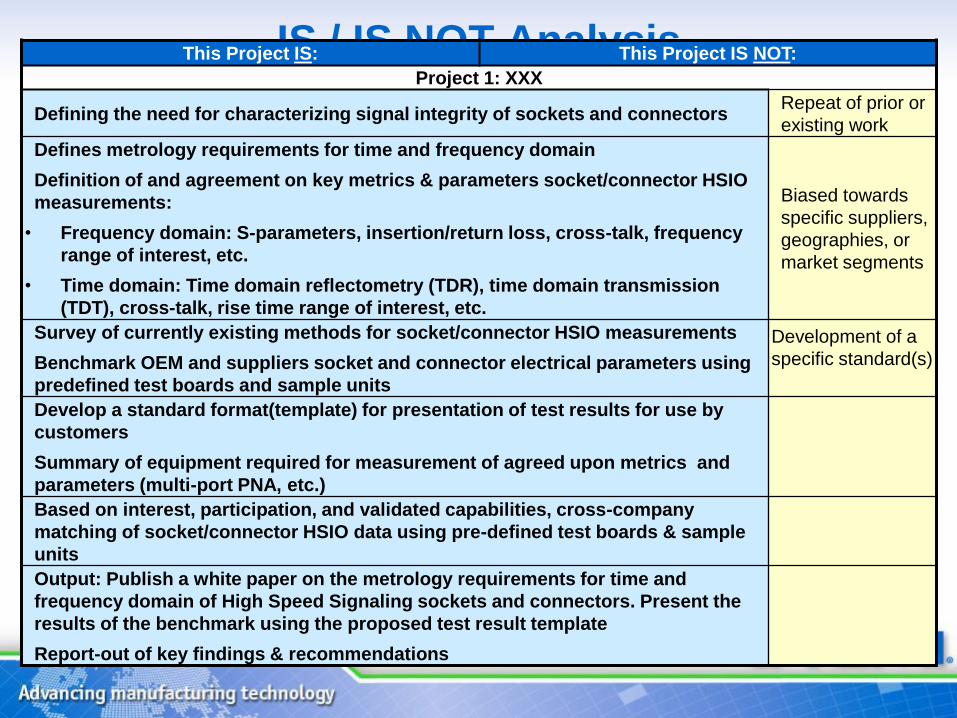
IS / IS NOT AnalysisThis Project IS: This Project IS NOT:
Project 1: XXX
Defining the need for characterizing signal integrity of sockets and connectorsRepeat of prior or
existing work
Defines metrology requirements for time and frequency domain
Definition of and agreement on key metrics & parameters socket/connector HSIO
measurements:
• Frequency domain: S-parameters, insertion/return loss, cross-talk, frequency
range of interest, etc.
• Time domain: Time domain reflectometry (TDR), time domain transmission
(TDT), cross-talk, rise time range of interest, etc.
Biased towards
specific suppliers,
geographies, or
market segments
Survey of currently existing methods for socket/connector HSIO measurements
Benchmark OEM and suppliers socket and connector electrical parameters using
predefined test boards and sample units
Development of a
specific standard(s)
Develop a standard format(template) for presentation of test results for use by
customers
Summary of equipment required for measurement of agreed upon metrics and
parameters (multi-port PNA, etc.)
Based on interest, participation, and validated capabilities, cross-company
matching of socket/connector HSIO data using pre-defined test boards & sample
units
Output: Publish a white paper on the metrology requirements for time and
frequency domain of High Speed Signaling sockets and connectors. Present the
results of the benchmark using the proposed test result template
Report-out of key findings & recommendations
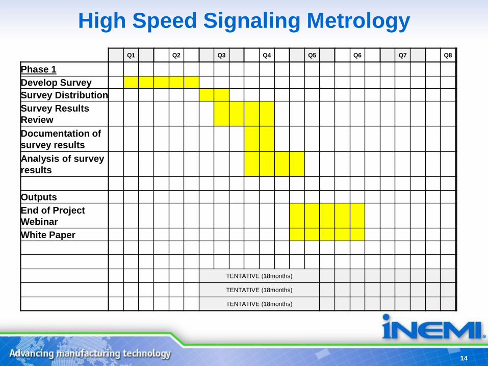
High Speed Signaling Metrology
14
Q1 Q2 Q3 Q4 Q5 Q6 Q7 Q8
Phase 1
Develop Survey
Survey Distribution
Survey Results
Review
Documentation of
survey results
Analysis of survey
results
Outputs
End of Project
Webinar
White Paper
TENTATIVE (18months)
TENTATIVE (18months)
TENTATIVE (18months)

Connector Standard
Reliability Test Recommendations
Project
Anne Ryan,
Alcatel-lucent

Connector Standard Reliability Test
Recommendations• BACKGROUND
– Test capabilities for socket reliability (such as temp cycle and
shock, failure analysis) are different across socket/ connector
manufacturers
– Associated criterion for ‘passing’ is not consistent
• PROPOSAL
– Scope/drive opportunity for industry level standard reliability
test conditions and equipment capabilities, FA capability and
criteria
– Drive common database / data formats of test results for
customers to use
16
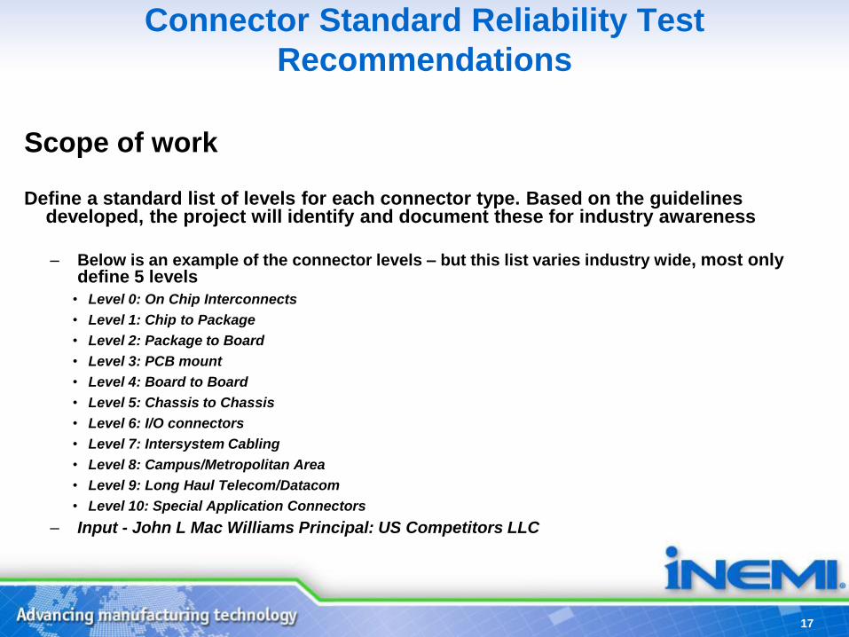
Connector Standard Reliability Test
Recommendations
Scope of work
Define a standard list of levels for each connector type. Based on the guidelines developed, the project will identify and document these for industry awareness
– Below is an example of the connector levels – but this list varies industry wide, most only define 5 levels
• Level 0: On Chip Interconnects
• Level 1: Chip to Package
• Level 2: Package to Board
• Level 3: PCB mount
• Level 4: Board to Board
• Level 5: Chassis to Chassis
• Level 6: I/O connectors
• Level 7: Intersystem Cabling
• Level 8: Campus/Metropolitan Area
• Level 9: Long Haul Telecom/Datacom
• Level 10: Special Application Connectors
– Input - John L Mac Williams Principal: US Competitors LLC
17

Connector Standard Reliability Test
RecommendationsScope of work (Continued)
• Survey Connector supplier’s/OEM list of packaging levels
• Develop connector standard list of packaging levels from outputs of survey
• Develop a guideline set of standard reliability test conditions for connector classes
(as an example apply to one connector class could be achieved in Phase I – others to follow in Phase II)
• Propose recommended Pass/Fail criterion for each test condition
18

Connector Standard Reliability Test
RecommendationsScope of work (Continued)
• Propose a standard test report format for presentation of test
results
• Alignment of critical elements that will be included in the connector
reliability report
19

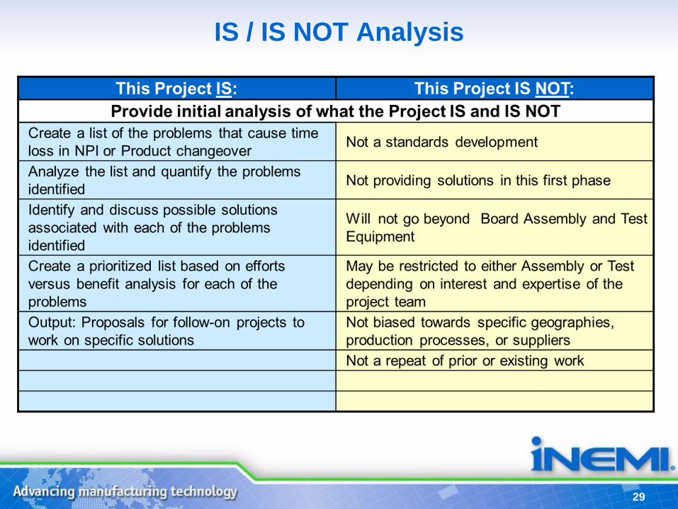
IS / IS NOT AnalysisThis Project IS: This Project IS NOT:
Provide initial analysis of what the Project IS and IS NOT
Drive standard Test Capabilities for socket reliability Development of a specific standard(s)
Create level of uniformity for how socket/connectors can be evaluated
for reliability (stresses, interpretation of electrical targets, and test
structure )
Repeat of prior or existing work
Gap Analysis of test capabilities
Review current classes of connectors and define standard list of levels
for one packaging type(Could be expanded further in Phase II)
Biased towards specific suppliers,
geographies, or market segments
Develop a set of standard reliability test conditions for one class of
connector(Phase I)
Develop Pass/Fail Criterion for each test condition
Step toward aligning a knowledge based connector certification
process
Alignment how to select the appropriate accelerated conditions
Alignment of standard methods for failure analysis
Alignment of critical elements that will be included in connector
reliability report
Output: Proposals for follow-on projects to work on specific solutions
Output: Develop a white paper which would define the levels for each
packaging class of connector, propose the test conditions associated
with one class and associated Pass/Fail criteria.

Schedule with Milestones
2014 2015
Q1 Q2 Q3 Q4 Q5 Q6 Q7 Q8
Task Phase 1
Phase 1.1 Survey supplier/OEM list of packaging
levels
Phase 1.2 Develop connector standard list of
package levels
Phase 1.3 Develop a standard reliability test
condition and criteria for one packaging
level
Phase 1.4 Propose Pass/Fail Criteria
Project Outputs
White Paper
Project Webinar
TENTATIVE (18months)

Details on Objective of Project Formation
Team
23
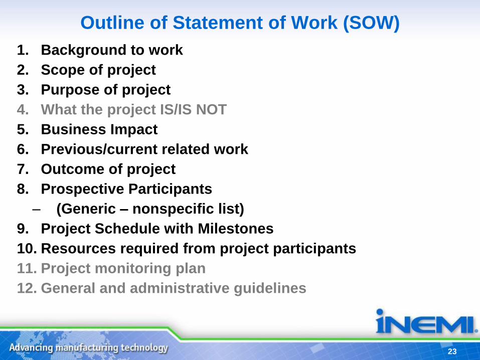
Outline of Statement of Work (SOW)
1. Background to work
2. Scope of project
3. Purpose of project
4. What the project IS/IS NOT
5. Business Impact
6. Previous/current related work
7. Outcome of project
8. Prospective Participants
– (Generic – nonspecific list)
9. Project Schedule with Milestones
10. Resources required from project participants
11. Project monitoring plan
12. General and administrative guidelines

24
Initiative Timeline
• First 1-3 meetings:
– Define overall project goal
– Break into project phases
– Engage key participants needed for project planning
•Second 3-6 meetings:
– Refine Statement of Work
– Prepare resource requirements
– Prepare project schedule

25
Outline of Statement of Work (SOW)
•Background to work
•Scope of project
•Purpose of project
•What the project IS/IS NOT
•Business Impact
•Previous/current related work
•Outcome of project
•Prospective Participants
•Project Schedule with Milestones
•Resources required from project participants
•Project monitoring plan
•General and administrative guidelines.

26
iNEMI Statement of Work – Basic Information
• Scope of Work – definition of what is to be done
– Describe what work will be done
– State the major goals of the project at the end of project deliverables
– Provide an approximate timeframe for major phases of the project and for completion
• Purpose of Project
– Explain how the project aligns to the roadmap and what gaps will be filled
– Will the project provide a complete solution or be part of a complex solution?
– List anticipated benefits to participants, to the iNEMI membership in general, and the industry

27
iNEMI Statement of Work (SOW)
•Business Impact – Provide information on what impact this project will have on
• Participating organization
• iNEMI member companies
• Industry as a whole
•Outcome of Project – List addressed issues that are expected to addressed and/or
resolved, e.g., identify gaps, report(s) on results of any testing, etc.
– List expected deliverables and project milestones
– Sharing Project Results: To be determined by the project team on what information will be shared outside of the team.
NOTE: All changes to SOW must be approved by TC

iNEMI Project Process
29
IS / IS NOT Analysis

30
• Address knowledge gap(s) of industry:– Common problem
– Best solved by working together
– Timed success that aligns to business needs
– Best manifested on complex far reaching issues
– Often includes reliability testing & verification
• Requires teamwork across multiple levels of the supply
chain:– Ensures efficient alignment of goals and investments of the
varied team players;
– Supports the company’s commercial interests.
• Delivers a coordinated industry wide response and capability
set. – OEM/ODM/EMS/Suppliers at multiple levels.
Successful iNEMI Projects

31
INPUT
SELECTION
DEFINITION
PLANNING
EXECUTION / REVIEW
CLOSURE
1
2
3
4
5
The Project Development Process - 5 Steps
“ Project”
Limited to committed Members
“ Initiative”
Open for Industry input
---------------------------------------------------------------------------------
0

32
− Organization
− Stakeholders
− Background
− Objectives
− Deliverables
− Benefits
− Skills required
− Risks
− Scope
− CostsAPPROVAL TO PROCEED
• Is it still valid?
• Is the market forecast valid?
• Do we have resources?
• What is current priority?
• What are the consequences of aborting now?
2 Definition
Decision after Review
TC

33
Planning
− Time estimates
− Initial schedule
− Resource analysis
− Optimization
− Risk review
− Issue resolution
− Prepare to implement
• Is the schedule acceptable to participating member companies?
• Are resources committed?
• Do we still want to do it?
• Is current priority correct?
3
Decision after Review
APPROVAL TO PROCEED
TC

34
Output of Planning Process
− Project Leadership
− SOW (Statement of Work)
− Document Describing the Project
− PS (Project Statement)
− Document Defining:
− What each Firm Will Contribute
− The rules for the Project
− Firm Commitment from Management
SOW and PS are described at www.inemi.org
3
APPROVAL TO PROCEEDTC

35
Potential Project Structure
1. Current Situation Analysis Phase
– Understand current systems and gaps/issues
– Defines Next Phase
– Builds participants Trust
2. Development Phase
– Drafts Tentative Requirements
– Validate effectiveness
3. “Marketing” Phase
– Work with all Stakeholders to obtain acceptance