cad/cam principles and applicationshome.iitk.ac.in/~jrkumar/download/me761a/lecture 3... ·...
TRANSCRIPT

Geometric
Transformation
Prof. Janakarajan Ramkumar Professor Department of Mechanical & Design Program IIT Kanpur, India.

• What is Design • Coordinate systems in CAD
• Transformation of geometry
• Colour Models
Contents
2

• Various types of coordinate systems used in displaying CAD
information
• Different types of geometric transformations used during CAD geometry generation and display and their evaluation.
• Learn about adding colour and shading to the display for better visualization.
• Mathematics required to display a 3D image on the 2D screen of the display device.
Objectives
3
• Design, usually considered in the context of applied arts, engineering,
architecture, and other creative endeavours, is used both as a noun and a verb.
• As a verb, "to design" refers to the process of originating and developing a plan for a product, structure, system, or component.
• As a noun, "a design" is used for both the final (solution) plan (e.g. proposal, drawing, model, description) or the result of implementing that plan (e.g. object produced, result of the process).
• More recently, processes (in general) have also been treated as products of design, giving new meaning to the term "process design”
What is Design?
4

Design is an Iterative Process (Ohsuga 1989)
What is Design?
5

• User-centered design: focuses on the needs, wants, and limitations of
the end user of the designed artifact.
• Use-centered design: which focuses on the goals and tasks associated with the use of the artifact, rather than focusing on the end user.
• KISS principle (Keep it Simple, Stupid): which strives to eliminate unnecessary complications
• There is more than one way to do it (TMTOWTDI): a philosophy to allow multiple methods of doing the same thing
• Murphy's Law (things will go wrong in any given situation, if you give them a chance)
Some Popular Design Approaches
6
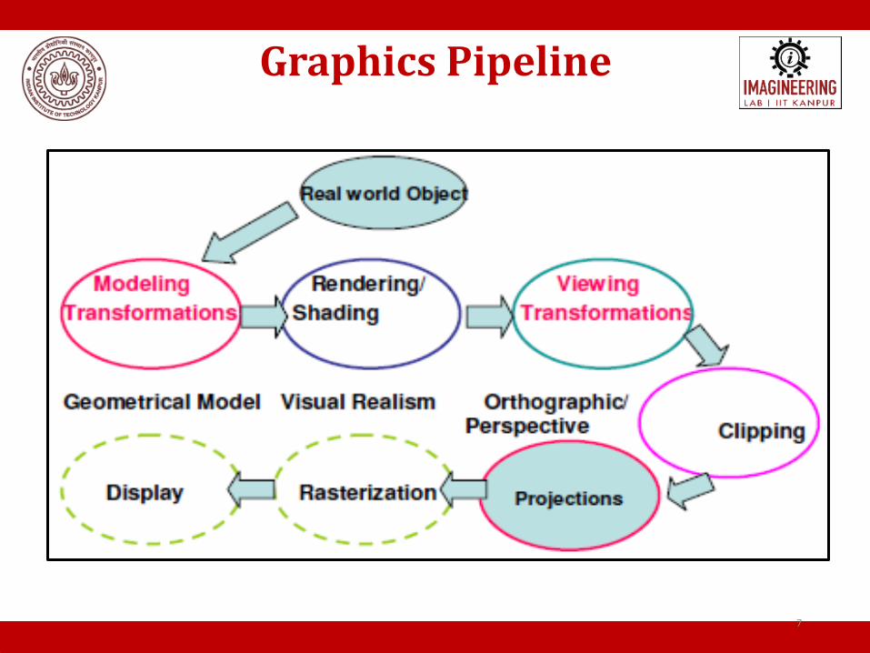
Graphics Pipeline
7

Computer Aided Design (CAD) is a set of methods and tools to assist product designers in :-
• Creating a geometrical representation of the artifacts they are designing
• Dimensioning, Tolerancing
• Configuration Management (Changes)
• Archiving
• Exchanging part and assembly information between teams, organizations
• Feeding subsequent design steps
• Analysis (CAE)
• Manufacturing (CAM)
What is CAD?
8

• Productivity Increase
• Automation of repeated tasks
• Supports Changeability
• Keep track of previous design iterations
• Communication enhances With other teams/engineers, e.g. manufacturing, suppliers
With other applications (CAE/FEM, CAM)
• Marketing, realistic product rendering
• Accurate, high quality drawings
• Mass Properties (Mass, Inertia)
• Collisions between parts, clearances
• Insert standard parts (e.g. fasteners) from database
Major Benefits of CAD
9

Generic CAD Process
10

• In a 2-D coordinate system the X axis generally points from left to right,
and the Y axis generally points from bottom to top.
• When we add the third coordinate, Z, we have a choice as to whether the Z-axis points into the screen or out of the screen.
• The right handed Cartesian coordinate system is used for defining the geometry of the parts.
Coordinate systems
Right/Left Hand Coordinate System
http://n64devkit.square7.ch/kantan/step3/1/1_3.htm
11

• In order to specify the geometry of a given solid, it is necessary to use a
variety of coordinate systems. Its Major classifications are:- World Coordinate System:- Also known as the "universe" or sometimes
"model" coordinate system. This is the base reference system for the overall model, ( generally in 3D ), to which all other model coordinates relate
User Coordinate System:- Also known as “working” coordinate system.
When it is difficult to define certain geometries using WCS, In such cases user coordinate system can be defined relative to the WCS. Display Coordinates:- This refers to the actual coordinates to be used for
displaying the image on the screen.
Coordinate systems
12

Coordinate systems
Rao, CAD/CAM Principles and Applications, 2010, TMH
A typical component to be modelled
13

Coordinate systems
A typical component to be modelled
WCS
WCS and UCS
Display Coordinates
Display Coordinates
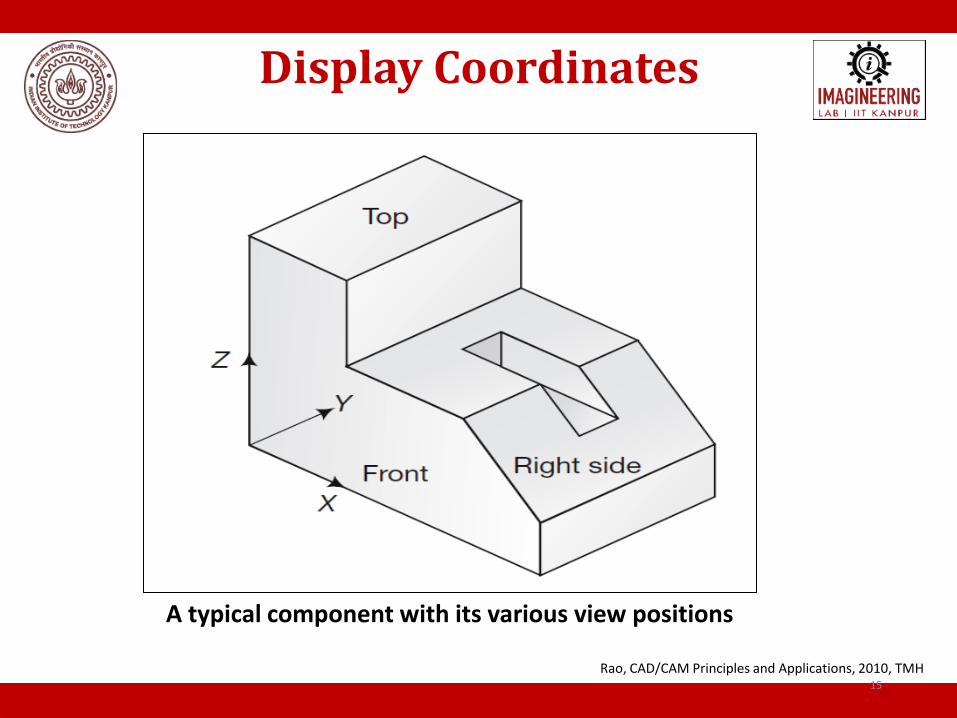
A typical component with its various view positions
Rao, CAD/CAM Principles and Applications, 2010, TMH
15

Display Coordinates
Various views generated from the model Rao, CAD/CAM Principles and Applications, 2010, TMH
16

17
•Essentially, computer graphics is concerned with generating, presenting and manipulating models of an object and its different views using computer hardware, software and graphic devices. •Usually the numerical data generated by a computer at very high speeds is hard to interpret unless one represents the data in graphic format and it is even better if the graphic can be manipulated to be viewed from different sides, enlarged or reduced in size. •Geometric transformation is one of the basic techniques that is used to accomplish these graphic functions involving scale change, translation to another location or rotating it by a certain angle to get a better view of it.
Introduction to Geometric transformation

• Translation
• Scaling
• Reflection or Mirror
• Rotation
Transformation of Geometry
18

Some of the possible geometric transformations Rao, CAD/CAM Principles and Applications, 2010, TMH
Transformation of Geometry
P*=[T]P Where [T] is
transformation matrix
19

Rao, CAD/CAM Principles and Applications, 2010, TMH
Transformation of Geometry
Translation of the point
20

• This moves a geometric entity in space in such a way that the new entity is parallel at all points to the old entity.
Old entity :- P = [X , Y], New entity: P* =[X*,Y*]
X* = X + dX or Y* = Y + dY
dYY
dXX
Y
XP
*
**
Translation
X1=X+Tx Y1=Y+Ty
21

22
Translate a triangle with vertices at original coordinates (10,20), (10,10), (20,10) by tx=5, ty=10.
Translation

• Scaling is the transformation applied to change the scale of an entity. • The change is done using scaling factors. There are two scaling
factors, i.e. Sx in x direction Sy in y direction.
Old entity :- P = [X , Y], New entity: P* =[X*,Y*]
[P*] = [Ts] . [P]
P* = [X*, Y*]= [Sx X, Sy dY]
Y
X
S0
0S =] P[
y
x*
Scaling
23

Scaling of a plane figure
Rao, CAD/CAM Principles and Applications, 2010, TMH
Scaling
24

25
Scale a triangle with respect to the origin, with vertices at original coordinates (10,20), (10,10), (20,10) by sx=2, sy=1.5.
Scaling

• Reflection or mirror is a transformation, which allows a copy of the
object is to be displayed while the object is reflected about a line or a plane.
• The object is rotated by180°.
• Types of Reflection: Reflection about the x-axis
Reflection about the y-axis
Reflection about an axis perpendicular to xy plane and passing through the origin
Reflection about line y=x
P* = [X*, Y*]= [T]P
Reflection or Mirror
26

• Reflection about x-axis: The object can be reflected about x-axis with the help of the following matrix
• Reflection about y-axis: The object can be reflected about y-axis with the help of following transformation matrix
[T]=
[T]=
Reflection or Mirror
27

• Reflection about an axis perpendicular to XY plane and passing through
origin:
[T]=
[T]=
• Reflection about line y=x:
Reflection or Mirror
28

Possible reflection (mirror) transformations of geometry
Rao, CAD/CAM Principles and Applications, 2010, TMH
Reflection or Mirror
29

30
Reflection or Mirror
Find reflected position of the Triangle (3,4), (6,4), (4,8) w.r.t X axis .

• It is a process of changing the angle of the object. Rotation can be
clockwise or anticlockwise. • For rotation, we have to specify the angle of rotation and rotation
point. Rotation point is also called a pivot point. It is print about which object is rotated
• The positive value of the pivot point (rotation angle) rotates an object in a counter-clockwise direction.
• The negative value of the pivot point (rotation angle) rotates an object in a clockwise direction.
y
x
y
x= ]P[ *
cossin
sincos
*
*
Rotation
31

32
x-axis
(x1,y1)
(x2,y2)
A
B r
(0,0)
y-axis
• To rotate a line or polygon, we must rotate each of its vertices.
• To rotate point (x1,y1) to point (x2,y2) we observe:
• From the illustration we know that:
sin (A + B) = y2/r cos (A + B) = x2/r
sin A = y1/r cos A = x1/r
IITK ME 761A Dr. J. Ramkumar
Rotation About the Origin

33
• From the double angle formulas:
sin (A + B) = sinAcosB + cosAsinB
cos (A + B)= cosAcosB - sinAsinB
• Substituting: y2/r = (y1/r)cosB + (x1/r)sinB
• Therefore: y2 = y1cosB + x1sinB
• We have x2 = x1cosB - y1sinB, y2 = x1sinB + y1cosB
1
1
2
2
2
cossin
sincos
y
x
y
x=] [P
P2 = R P1
(x1)
(y1)
(cosB -sinB)
(sinB cosB)
(x2)
(y2) = =
Rotation About the Origin

Rotation
34
(x1,y1)
(x2,y2)
A
r
(0,0)
y-axis
Clockwise Rotation Anti-Clockwise Rotation
(x1,y1)
(x2,y2)
A
r
(0,0)
y-axis

35
• Three successive rotations about the three axes
rotation about the z axis rotation about the y axis rotation about the x axis
1000
0100
00cossin
00sincos
1000
0cos0sin
0010
0sin0cos
1000
0cossin0
0sincos0
0001
Rotation about axes

36
100
sin)cos1(cossin
sin)cos1(sincos
100
10
01
100
0cossin
0sincos
100
10
01
rr
rr
r
r
r
r
xy
yx
y
x
y
x
,,,, rrrrrr yxRyxTRyxT
Translate Rotate Translate
(xr,y
r)
(xr,y
r)
(xr,y
r)
(xr,y
r)
Pivot-Point Rotation

Rotation transformation
Rao, CAD/CAM Principles and Applications, 2010, TMH
Rotation
37

38
Rotation
Rotate line AB whose endpoints are A(2,5) and B(6,2) about origin through 30* clockwise direction.

1100
10
01
1
*
*
* y
x
dY
dX
y
x
P
Homogeneous Representation
Concatenation of transformations • [P*] = [Tn] [Tn-1] [Tn-2] .. [T3] [T2] [T1]
39

• Translate the point P to O, the origin of the axes system.
• Rotate the object by the given angle
• Translate the point back to its original position.
Rotation about an arbitrary point
40

Rotation about an arbitrary point
Rao, CAD/CAM Principles and Applications, 2010, TMH 41

• Translate the mirror line along the Y-axis such that the line passes through the origin, O
• Rotate the mirror line such that it coincides with the X-axis.
• Mirror the object through the X-axis.
• Rotate the mirror line back to the original angle with X-axis.
• Translate the mirror line along the Y-axis back to the original position.
Reflection about an arbitrary line
42

Reflection about an arbitrary line
Rao, CAD/CAM Principles and Applications, 2010, TMH 43

• Translate the point P to O, the origin of the axes system.
• Rotate the object by the given angle
• Translate the point back to its original position.
Scaling about an arbitrary point
44

Scaling about an arbitrary Point
45

11000
100
010
001
1
*
*
*
z
y
x
dZ
dY
dX
z
y
x
3D Transformations
46

11000
0100
0010
0001
1
*
*
*
z
y
x
z
y
x
3D Reflection
47

11000
0100
00cossin
00sincos
1
*
*
*
z
y
x
z
y
x
3D Rotation about Z-axis (XY plane)
48

49
• Scaling, reflection and rotation transformation are in the form of Matrix multiplication but translation is in the form of matrix addition.
• This makes it inconvenient to combine transformation with translation.
• It is desirable to express all geometric transformation in the form of matrix multiplication only.
• Representing points by their homogeneous coordinates provides an effective way to unify the description of geometric transformations as matrix multiplications.
• In homogeneous coordinates, an n-dimensional space is mapped into
(n + 1) - dimensional space.
Homogeneous Representation

50
• In 3D space, a point P with Cartesian coordinates (x, y, z) has the homogeneous coordinates (x*, y*, z*, h) where h is any scalar factor ≠ 0.
• The two types of coordinates are related to each other by the following equation:
• Homogeneous coordinates remove many anomalous situations encountered in Cartesian geometry .
Homogeneous Representation

51
• The homogeneous translation transformation can now be written as a matrix multiplication by adding the component of 1 to each vector, and using a matrix as follows:
1
.
100
10
01
1
*
*
y
x
y
x
y
x
d
d
11
*
*
d
d
yyy
xxx
2D translation is now 3x3.
Homogeneous Representation
3D translation is now 4x4.

52
• The homogeneous scaling transformation can now be written as a matrix multiplication by adding the component of 1 to each vector, and using a matrix as follows:
100
00
00
y
x
s
s
S
2D Scaling is now 3x3.
3D Scaling is now 4x4.
Homogeneous Representation

53
• The homogeneous rotation transformation can now be written as a matrix multiplication by adding the component of 1 to each vector, and using a matrix as follows:
Homogeneous Representation
2D rotation is now 3x3.
3D Scaling is now 4x4.
1
.
100
0cossin
0sincos
y
x
Rz

54
Homogeneous Representation
2D reflection is now 3x3.
3D reflection is now 4x4.
100
010
001
M
• The homogeneous mirror or reflection transformation can now be written as a matrix multiplication by adding the component of 1 to each vector, and using a matrix as follows:

55
Concatenated Transformations
• In practice a series of transformations may be applied to geometric models and thus, combining or concatenating transformations is necessary.
• Concatenated transformations are simply obtained by multiplying the matrices of the corresponding individual transformations.
• If we apply n transformations to a point starting with transformation 1, with [T1], and ending with transformation n, with [Tn], the concatenated transformation of the point is given by:

56
Concatenated Transformations

57
Q. The vertices of a triangle are situated at points (15, 30), (25, 35) and (5, 45). Find the coordinates of the vertices if the triangle is first rotated 10° counter clockwise direction about the origin and then scaled to twice its size.
Multiplying the end points with the transformation matrix, we get new coordinates as (51.276, 73.86), (75.896, 96.16) and (39.408, 87.48)
P
111
453530
52515
PT P *
Concatenation

58
• Rotate the box 90 degrees around an axis that runs through P and is vertical on the xy-plane. The box has side edges of length 1 and the coordinate P(2,3,4) and Q (2,4,4), find the modified P2 and Q2 .
Concatenated Transformations

• Design Methodology originated from need to final product using
computers graphics was done.
• Depending upon the type of graphic display used, it is necessary to be familiar with a number of different coordinate systems to facilitate the graphic construction as well as display.
• Coordinate Systems : World Coordinate system User coordinate system Display Coordinates
• Homogeneous coordinate system • Concatenated Transformations
Summary
59
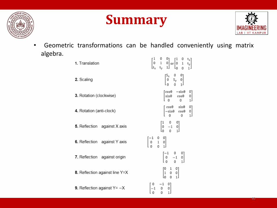
• Geometric transformations can be handled conveniently using matrix
algebra.
Summary
60

1. Rao, P.N., 2004. CAD/CAM: principles and applications. Tata McGraw-Hill
Education.
2. Zeid, I., 1991. CAD/CAM theory and practice. McGraw-Hill Higher Education.
3. Lee, K., 1999. Principles of CAD/CAM/CAE systems. Addison-Wesley
Longman Publishing Co., Inc.
4. https://www.javatpoint.com/computer-graphics-homogeneous-coordinates
References
61

Thank you!!

63
Translate a triangle with vertices at original coordinates (10,20), (10,10), (20,10) by tx=5, ty=10.
Translation

64
Scale a triangle with respect to the origin, with vertices at original coordinates (10,20), (10,10), (20,10) by sx=2, sy=1.5.
Scaling

65
Reflection or Mirror Find reflected position of the Triangle (3,4), (6,4), (4,8) w.r.t X axis .

66

67
Concatenated Transformations

68
Concatenated Transformations

69
• Rotate the box 90 degrees around an axis that runs through P and is vertical on the xy-plane. The box has side edges of length 1 and the coordinate P(2,3,4) and Q (2,4,4), find the modified P2 and Q2 .
Concatenated Transformations

70
• With our knowledge about transformations it should be a good
strategy to:
1. Move the point P in to the z-axis, the matrix T1
2. Rotate around the z-axis, the matrix R
3. Move the box back, the matrix T2’
• We use the matrices in the opposite direction, and multiply from
the left.
We make the matrix M=T2·R·T1, and find Q2=M·Q and P2=M·P.
After the operation the point Q (2,4,4) should
end up in Q2(1,3,4), and P(2,3,4) should
remain in P2(2,3,4).

71
Example – for the RPP given by the matrix below obtain 3D reflection through xy – plane.
[X*]
becomes Positive

Example – Transform the given position vector [ 3 2 1 1] by the following sequence of operations (i) Translate by –1, -1, -1 in x, y, and z respectively (ii) Rotate by +30°about x-axis and +45°about y axis The concatenated transformation matrix is:

73
Example – Consider the following cube. Rotate it by 30º about an axis x’ passing through its centroid

74