introduction to non-traditional machining processeshome.iitk.ac.in/~jrkumar/download/unconventional...
TRANSCRIPT
Introduction to Non-Traditional MachiningProcesses
Prof. J. Ramkumar
Department of Mechanical EngineeringIIT Kanpur
March 26, 2018

So Far

Limitations of Conventional Machining Methods
I Increased workpiece hardness : decreased economic cuttingspeed. Hence, lower productivity.
I Rapid improvements in the properties of materials (hardness,strength, etc)
I Requires much superior quality of tool materials.
I Tool material hardness should be greater than workpiecehardness.

Evolution of Advanced Machining Processes(AMPs)
I Many Engineering materials are having much superiorproperties such as ultra high strength , hardness, very hightemperature resistance difficult to machine by convenventionalmachining methods.Ex :Tungsten Carbide, Stainless Steel, Titanium and its alloysetc
I If work piece material hardness is greater than the toolmaterial hardness. How are we going to machine such a workpiece material ?
Product Requirement
I Complex shapes
I Machining in inaccessible areas
I Low tolerances (say, 0.01 mm)
I Better surface integrity (no surface defects, etc.)
I High surface finish (Nano-level Ra value)
I Miniaturization of products (examples: landline phone &mobile, old computers & laptop, etc.)
I High MRR
I High production rate while processing difficult to machine.
I Low cost of production .
I Precision and ultraprecision machining
I Requires material removal in the form of atoms and / ormolecules

Machining of Complex Shaped Workpieces

Important characteristics of Advance Machining Processes
I Process performance is independent of workpiece :Strength &Hardness are not a barrier.
I Performance depends on thermal, electrical and chemicalproperties of workpiece materials.
I Uses different kinds of energy in direct form.
I In general, low MRR but better quality products .
I Comparatively high initial investment cost of machine toolsand high operating cost

Classification of AMPs,Based on the Kind of Energy used

Classification of AMPs, Based on Properties of workmaterial
I Applicable only for Electrically Conducting Materials : ECM,EDM, EBM.
I Applicable for both electrically conducting & non - conductingmaterials: USM , AJM, LBM, etc.
I Applicable for Non Magnetic materials : MAF, MRF, etc.
I Thermal conductivity, Reflectivity, etc. also play an importantrole in some processes: LBM

Classification of AMPs, Based on Electrical Conductivity

Classification of µ-Machining
Mechanical Machining
Prof. J. Ramkumar
Department of Mechanical EngineeringIIT Kanpur
March 26, 2018
Outline
Abrasive Jet Machining
Water Jet Machining
Abrasive Water Jet Machining
Ice Jet Machining
Ultrasonic Machining
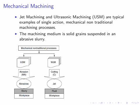
Mechanical Machining
I Jet Machining and Ultrasonic Machining (USM) are typicalexamples of single action, mechanical non traditionalmachining processes.
I The machining medium is solid grains suspended in anabrasive slurry.

Abrasive Jet Machining: Machined products

Abrasive Jet Machining: Machined products
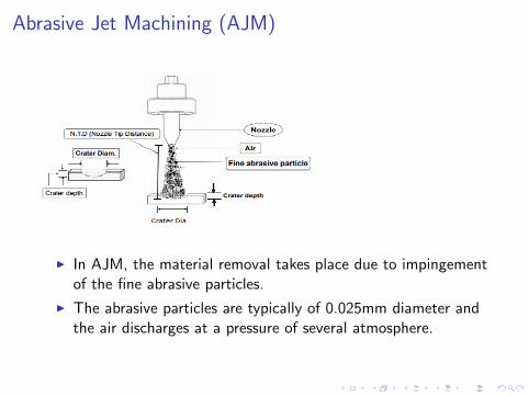
Abrasive Jet Machining (AJM)
I In AJM, the material removal takes place due to impingementof the fine abrasive particles.
I The abrasive particles are typically of 0.025mm diameter andthe air discharges at a pressure of several atmosphere.

Mechanics of AJM
I Abrasive particle impinges on the work surface at a highvelocity and this impact causes a tiny brittle fracture and thefollowing air or gas carries away the dislodged small workpiece particle.

Mechanics of AJM
I Flaring of the Jet:- Cavity dimension changes with a changein NTD.
I Abrasive particles repeatedly hit on the work surface.
I Brittle fracture separates out tiny particles (wear particles) toproduce a cavity. Cavity width greater than or equal to Nozzleinner diam. (Depends on NTD).
I Cavity depth depends on work piece feed rate, abrasiveparticle mass (or density) and pressure (or velocity of the jet).
I Stray Cutting: Due to increase in NTD the jet diameter goeson increasing.
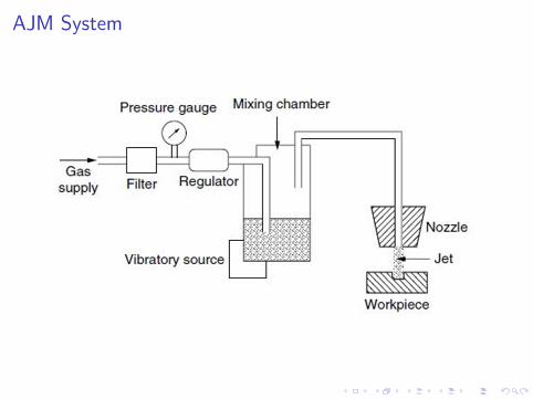
AJM System

AJM Process Parameters
I For successful utilization of AJM process, it is necessary toanalyse the following process criteria.1. Material removal rate.2. Geometry and surface finish of the workpiece.3. Wear rate of the nozzle.
I AJM processes are generally influenced by the followingprocess parameters.
I Abrasives:Material shape size(µm) m(g/min)
Abrasives Al2O3, SiC Irregular 10− 50 2− 20

AJM Process Parameters contd.
I Carrier Gas:
Composition ρ(kg/m3) V (m/s) P(bars)
Carrier Gas Air,CO2,N2 1.3 500− 700 2− 10
I Abrasive Jet:
SOD(mm) Impinge V (m/s) Mixing ratio
Abrasive Jet 0.5-15 60− 90◦ 100− 300 Vabr/Vgas
I Nozzle:
Material Diameter(mm) Life(hrs) NTD(mm)
Nozzle WC,Sapphire 0.2-0.8 12-300 0.25-75
I Note: SOD-Stand of Distance, NTD: Nozzle to Tip Distance

Mathematical Modelling of AJM
I Assumptions:1. Abrasives are rigid and spherical in shape having diameterdg (grit diameter).2. Kinetic energy of particle is used to cut the material.3. for brittle materials, volume of material removal isconsidered to be hemispherical in shape having diameter equalto the chord length of the indentation (2r).4. For ductile materials, volume of material removal isassumed to be equal to the indentation volume due toabrasive partical impact.

Mathematical Modelling of AJM
Case-1: Brittle MaterialsI Indentation depth(δ) estimation:
AB2 − AC 2 = BC 2 (1)

Mathematical Modelling of AJM contd.
(dg2
)2
−
(dg2− δ
)2
= r2 (2)
(dg2
)2
−
(dg2
)2
− (δ)2 + 2δdg2
= r2 (3)
r2 = −δ2 + dgδ (4)
As δ is small, we can neglect δ2
r2 = dgδ (5)
r =√
dgδ (6)

Mathematical Modelling of AJM contd.
I For Brittle material:Volume of material removal in brittle material is the volume ofthe hemispherical impact crater and is given by:
ΓB =1
2
[4
3πr3]
=1
2
[4
3π(r2)
32
]=
1
2
[4
3π(dgδ)
32
]=
2
3π(dgδ)
32
(7)Assume the grits Velocity(V). So the Kinetic Energy is
KE =1
2MV 2 (8)
where M is expressed by this expressionM = mass of single abrasive grit=volume of grit * Density ofabrasive material(ρa)

Mathematical Modelling of AJM contd.
I For Brittle material contd.:where Volume of grit is
Volume of grit= 43π
(dg2
)3
= π6d
3g
Then the KE for single grit is
KE =1
2MV 2 =
1
2
(π
6d3gρa
)V 2 (9)
On impact, work material should be subjected to maximumforce F, which would lead to indentation of δ.

Mathematical Modelling of AJM contd.
I For Brittle material contd.:
Here, you can see that the force is linearly varies with δ(F = aδ)
Work done =∫ δ0 aδdδ = a
2δ2
As F = aδ, so a = Fδ
So, the work done is Fδ2
So, Work done by the single grit during such indentation is
W =F δ
2(10)

Mathematical Modelling of AJM contd.
I For Brittle material contd.:Also we know the flow stress/Brinell hardness ofmaterial(σw ). So,
F = stress ∗ area = σwπr2 = σwπdgδ (11)
Using Eq. 10 and Eq. 11, we get
W =F δ
2=σwπdgδ
2
2(12)
It is assumed that kinetic energy of the abrasives is fully usedfor material removal.Kinetic energy of the particle = Work done by the particleUsing Eq. 9 and Eq. 12, we get
1
2MV 2 =
1
2
(π
6d3gρa
)V 2 =
σwπdgδ2
2(13)

Mathematical Modelling of AJM contd.
I For Brittle material contd.:Simplify the equation 13. we get δ as
δ = Vdg
√ρa
6σw(14)
I MRR in AJM: MRR=(Volume of material removed pergrit)*(Number of abrasive particle impacting per unit time).Z(Z = 6ma
πd3gρa
) is the number of abrasive particle impacting per
unit time.(where ma is the abrasive mass flow rate)
MRR =
(2
3π(dgδ)
32
)∗ Z (15)
using δ from Eq. 14, we get
MRR =2
3πZd3
gV32
(ρa
6σw
) 34
(16)

Mathematical Modelling of AJM contd.
I For Brittle material contd.:
MRR∝ maV3/2
ρ1/4a σ
3/4w
(17)

Mathematical Modelling of AJM contd.
I For Ductile material:For ductile material, volume of material removal in singleimpact is equal to the volume of the indentation and isexpressed as:
ΓD = πδ2[dg2− δ
3
]=πdgδ
2
2(18)
Home Work: Derive the MRR for ductile material in AJMProcess?Given: ΓD , Eq. 19Hint: Similar to Brittle material
MRRD =maV
2
2σw(19)

Parametric Analysis in AJM
I Effect of Nozzle Tip Distance (NTD) on cavity diameter

Parametric Analysis in AJM
I Effect of Nozzle Tip Distance (NTD) on MRR
I The NTD not only affects the MRR from the work surface butalso the shape and size of the cavity produced.
I when the NTD increases, the velocity of the abrasive particlesimpinging on the work surface increases due to theiracceleration after they leave the nozzle. This increases theMRR. With a further increase in the NTD, the velocityreduces due to the drag of the atmosphere which initiallychecks the increase in MRR and then decreases it.

Parametric Analysis in AJM
I Effect of Abrasive flow rate on MRR
I As the flow rate increases upto maxima, More number ofabrasive particles hit the surface. this increases the MRR.
I If flow rate is greater than the optimum, velocity of the jetdecreases hence MRR also decreases.

Parametric Analysis in AJM
I Effect of Nozzle Pressure on MRR
I Little effect on MRR
I Kinetic Energy removes material: Due to erosive action
I Certain minimum velocity for the given material of workpiece.

Parametric Analysis in AJMI Effect of Mixing Ratio on MRR
I Note: Mixing Ratio(m) is the ratio of volume flow rate ofabrasive to the volume flow rate of carrier gas.(α =massratio)α is the ratio of mass flow rate of abrasive to the massflow rate of abrasive and gas carrier
m =Va
Vg
α =ma
ma+g(20)

Process Capabilities of AJM
I Low MRR
I Intricate Details Can be Produced
I Narrow Slots (0.12 to 0.25 mm) can be made
I Low Tolerances (−0.12 to +0.12mm) can be obtained
I Minimization of Taper Angle of Nozzle wrt Work Piece
I Thin Sectioned, Brittle Material, Inaccessible areas can beeasily machined
I Almost no surface damage

Applications of AJM
I Manufacture of Electronic Devices including Fragilecomponents
I Deburring of Plastics, Nylon, Teflon Parts
I Deflashing of Small Casting
I Drilling Glass Wafers, etc.
I Cutting, marking, engraving, cutting thin sectioned.
I Glass frosting

Water Jet Machining
I It has multidirectional cutting capacity with no heat produced.
I Cuts can be started at any location without the need forpredrilled holes.
I The burr produced is minimal.
I Grinding and polishing are eliminated, reducing secondaryoperation costs.
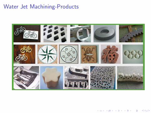
Water Jet Machining-Products

Abrasive Water Jet Machining
I Cut virtually any material.
I Cut thin or thick stuff and No heat generated.
I Abrasive Water jet cutting can be easily used to produceprototype parts very efficiently.

Abrasive Water Jet Machining- Products
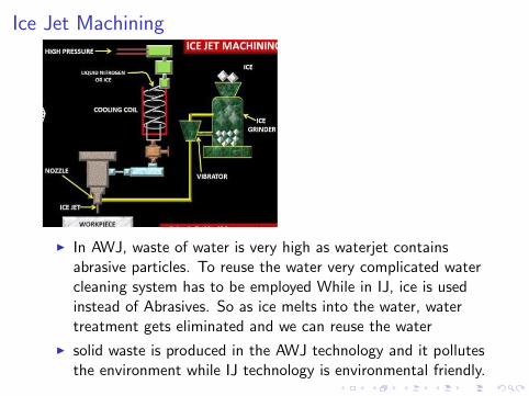
Ice Jet Machining
I In AWJ, waste of water is very high as waterjet containsabrasive particles. To reuse the water very complicated watercleaning system has to be employed While in IJ, ice is usedinstead of Abrasives. So as ice melts into the water, watertreatment gets eliminated and we can reuse the water
I solid waste is produced in the AWJ technology and it pollutesthe environment while IJ technology is environmental friendly.

Ultrasonic Machining (USM) Process
I The basic USM process involves a tool vibrating with a lowamplitude and very high frequency and a continuous flow ofan abrasive slurry in the small gap between tool & work piece.
I The tool is gradually fed with a uniform force.
I The impact of the hard abrasive grains fractures the hard andbrittle work surface, resulting in the removal of the workmaterial in the form of small wear particles.
I The tool material being tough and ductile wears out at a
much slower rate

USM:Products

USM:Products

Ultrasonic Machining (USM) Process contd.
I Mechanics of USM: 1. The hammering of the abrasiveparticles on the work surface by the tool.2. The impact of free abrasive particles on the work surface.3. The erosion due to cavitation.4. The chemical action associated with the fluid used.

Ultrasonic Machining (USM) Process contd.
I Mechanics of USM contd.: 1. The position ′A′ indicatesthe instant the tool face touches the abrasive grain.2. The period of movement from ′A′ to ′B ′ represents theimpact.3. The indentations, caused by the grain on the tool and thework surface at the extreme bottom position of the tool fromthe position ′A′ to position ′B ′ is ′h′ (the total indentation).

Ultrasonic Machine
I It consists of the following machine components: The acoustichead, feeding unit, tool, abrasive slurry and pump unit, bodywith work table.

USM Acoustic Head
I The Acoustic heads function is to produce a vibration in thetool.
I It consists of a generator for supplying a high frequencyelectric current, a transducer to convert this into a mechanicalmotion (in form of a high frequency vibration).
USM Acoustic Head
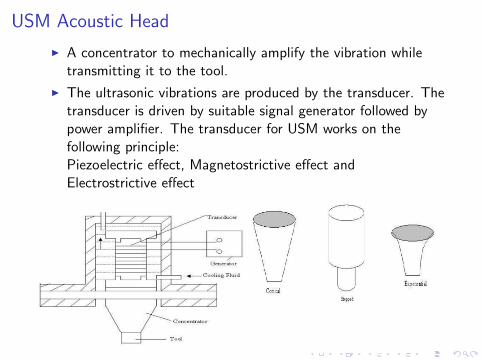
I A concentrator to mechanically amplify the vibration whiletransmitting it to the tool.
I The ultrasonic vibrations are produced by the transducer. Thetransducer is driven by suitable signal generator followed bypower amplifier. The transducer for USM works on thefollowing principle:Piezoelectric effect, Magnetostrictive effect andElectrostrictive effect

USM Abrasive Slurry
I The most common abrasives are Boron Carbide (B4C ), SiliconCarbide (SiC), Corrundum (Al2O3), Diamond and Boronsilicarbide.
I B4C is the best and most efficient among the rest but it isexpensive.
I SiC is used on glass, germanium and most ceramics.
I Diamond dust is used only for cutting Daimond and Rubies.
I Water is the most commonly used fluid although other liquidssuch as Benzene, Glycerol and oils are also used

M.C. Shaw Model of USM Contd.
I Assumptions:1. The rate of work material removal is proportional to thevolume of the work material per impact.2. The rate of work material removal is proportional to theno. of particles making impact per cycle.3. The rate of work material removal is proportional to thefrequency (no. of cycles per unit time).4. All impacts are identical.5. All abrasive grains are identical and spherical in shape.Thus, volume of work material removal rate (Q)
Q ∝ VZν (21)
I Note:V = volume of the work material removal per impact, Z= number of particles making impact per cycle, ν = frequency

M.C. Shaw Model of USM Contd.
I Consider the impact of a rigid, spherical abrasive graindiameter d on the work surface and D is diameter of theindentation at any instant and hw (= h in figure) is thecorresponding depth of penetration.(
D
2
)2
=
(d
2
)2
−(d
2− hw
)2
(22)

M.C. Shaw Model of USM Contd.
D2 = d2 − (d − 2hw )2 or D2 = 4dhw − 4h2w (23)
Since hw is small, so 4h2w is very small. so, neglect it
D ≈ 2√
dhw (24)
Volume of material removal from the work piece in brittle materialis the volume of the hemispherical impact crater and is given by:
Γw =2
3π
(D
2
)3
=2
3π(dhw )3/2 (25)
So, from Eq. 21 and 25
MRRw (Q) = ΓwZν =2
3π(dhw )3/2Zν (26)

M.C. Shaw Model of USM Contd.
Since the abrasive has irregular shape. So, the actual indentation isoccurs by the effect of spherical projections(with diameter d1) asshown in the figure.(it is observed that d1 = µd2)So, the actual Volume of material removal from the work piece is:
Γw =2
3π
(D
2
)3
=2
3π(d1hw )3/2 (27)
So, Actual MRR from Eq. 27MRRw (Q) = ΓwZν =
2
3π(d1hw )3/2Zν (28)

M.C. Shaw Model of USM Contd.
I Since the mean speed of the tool is low, the mean static feedforce F applied to the tool must be equal to the mean force ofthe tool on the grains.
I Duration of an impact is ∆T and the maximum value of theimpact force F is Fmax .

M.C. Shaw Model of USM Contd.
I The nature of variation of F with time is shown in fig.6.10.(previous slide) So, It will not be very much erroneousto assume the nature of variation of F to be traingular.Now,
F =1
T
∫ T
0F (t)dt ≈ 1
2Fmax
∆T
T(29)
I where T is the time period of each cycle.

M.C. Shaw Model of USM Contd.
If the distance travelled by the tool from the position A to theposition B is h(the total indentation), then
h = hw + ht (30)
If A is the amplitude of oscillation of the tool. then the averagevelocity of the tool during the quarter cycle O to B is given byA/(T/4)

M.C. Shaw Model of USM Contd.
So, the time required to travel from A to B is
∆T ≈ h
A.T
4=
(hw + ht
A
)T
4(31)
Subsitute equation 31 in 29, we obtain
F ≈ 1
2Fmax
(hw + ht
A
)T
4
1
T(32)
or
Fmax ≈8FA
hw + ht(33)

M.C. Shaw Model of USM Contd.
I Z is the number of abrasive grains are simultaneously incontact during a period ∆T . So, Force per grain is Fmax/Z
I The approximate area of contact on the work surface pergrain is π
4D2 = πd1hw .
I Therefore, the maximum stress developed in the work piece isgiven as
σw =Fmax
πZd1hw(34)
Using the Equation 33 in 34, we get
σw =8FA
πZd1hw (hw + ht)(35)

M.C. Shaw Model of USM Contd.
I It is quite reasonable to assume that the depth of penetrationis inversely proportional to the flow stress of the material aslong as other parameters are constant. So, h ∝ 1/σ.
I If σt and σw are the stresses developed in the tool and work,the ratio of the corresponding indentation is given as
hthw
=σwσt
= λ (36)
Since the flow stress σ and the brinell HradnessH(σw = Hw , σt = Ht) are the same, equation 35 and 36yield
h2w =8FA
πZd1Hw (1 + λ)(37)

M.C. Shaw Model of USM Contd.
I Again, it may be assumed that the number of grains acting isinversely proportional to the square of the diameter of eachgrain for a given area of the tool face. Therefore,
Z ∝ C
d2or Z = χ
C
d2(38)
where C is the concentration of the abrasive grains in theslurry and χ is a constant of proportionality.
I A d1 = µd2. so the hw becomes
hw =
√8FA
πχCµHw (1 + λ)(39)

MRR in USM process
So, From Equation 28 and 39, we get
MRR(Q) =2
3π
(µd2
(8FA
πχCµHw (1 + λ)
)1/2)3/2
χC
d2ν (40)
MRR(Q) =2
3π
14µ
34χ
14dF
34A
34C
14
H34w (1 + λ)
34
ν (41)
MRR(Q) ∝ dF34A
34C
14
H34w (1 + λ)
34
ν (42)
d is the nominal diameter, d1 is the average diameter ofprojection(diameter of the indenting projections), C: concentrationof the abrasive grains in the slurry. F: mean static feed force, A:amplitude of oscillation of tool, Hw : work piece hardness, λ = Hw
Ht,
χ is a constant, Z: number of grains are simultaneously in contact

USM Process Parameters
I Frequency
I Amplitude
I Static loading (feed force),
I Hardness ratio of the tool and the workpiece,
I Grain size,
I Concentration of the abrasive in the slurry.

USM MRR vs Frequency and Amplitude
I With an increase in frequency of the tool head the MRRshould increase proportionally. However, there is a slightvariation in the MRR with frequency.
I When the amplitude of the vibration increases the MRR isexpected to increase.
I The actual nature of the variation is shown in Figure

USM MRR vs abrasive diamter and concentration
I MRR should also rise proportionately with the mean graindiameter ′d ′.
I When ′d ′ becomes too large, the crushing tendency increases.
I Concentration of the abrasives directly controls the number ofgrains producing impact per cycle. MRR is proportional toC 1/4 so after C rises to 30 percantage MRR increase is notvery fast

USM MRR vs Feed Force
I MRR increases with increasing feed force but after a certaincritical feed force it decreases because the abrasive grains getcrushed under heavy load

USM, Dependence of Surface Finish on Grain Size
I The figure shows that the surface finish is more sensitive tograin size in case of glass which is softer than tungstencarbide. This is because in case of a harder material the sizeof the fragments dislodged through a brittle fracture does notdepend much on the size of the impacting particles

Summary of USM

Electric Discharge Machining
Prof. J. Ramkumar
Department of Mechanical EngineeringIIT Kanpur
March 26, 2018

Electric Discharge Machining (EDM):Products

Electric Discharge Machining (EDM)
I Electro Discharge Machining (EDM) is an electro-thermalnon-traditional machining process, where electrical energy isused to generate electrical spark and material removal mainlyoccurs due to thermal energy of the spark.
I EDM is mainly used to machine difficult-to-machine materialsand high strength temperature resistant alloys. EDM can beused to machine difficult geometries in small batches or evenon job-shop basis.
I Work material to be machined by EDM has to be electricallyconductive.
Electric Discharge Machining (EDM)
I Plasma formation and Spark generation in EDM:1. Voltage across the electrodes reaches the breakdownVoltage2. Dielectric Breakdown: Formation of plasma3. Spark Generation at the point of lowest IEG4. Melting and Vaporization of Work Piece Material5. Bubble generation and their Expansion6. Plasma Channel Explodes

Electric Discharge Machining (EDM)I Plasma formation and Spark generation in EDM contd.:
I EDM gap phenomenon and material removal mechanism withpositive polarity Stages 1 to 4: normal discharges; Stage 5:repeated discharges leading to debris accumulation; and Stage6: excess debris causing spurious discharges through clustersof debris (middle) as well as by individual debris particle

Electric Discharge Machining (EDM)

Elements of EDM Process
I Tool Electrode: 1. Good Electric conductivity, High thermalDiffusivity, High melting and boiling point, good machinablityetc2. Examples are graphite, brass, copper, tungsten etc
I Work piece Material: Any material which is electricallyconductive can be machined through EDM
I Power Supply: Resistance capacitance(RC) and Transistortype circuits are used. Transistor circuits(TC) are incapable toproduce nano pulses. TC is used where high MRR required.
I Servo System: To maintain a constant spark gap betweenelectrodes.
I Dielectric Fluid: It acts as the insulator medium betweentool and work piece. Examples are Kerosene, De-ionizedWater, air, mineral oil etc.

Variants of EDM process

Different power generators in EDMI Resistance Capacitance based power supply
The RC circuit is basically a relaxation oscillator with aresistor and a capacitor, as illustrated in Fig.. It is a simple,reliable, robust, low-cost power source for EDM. It canprovide very small pulse energy and is used extensively inmicro EDM and finishing EDM to achieve fine surface finish.The drawback of RC generator is the lack of precision control,particularly for timing and slow charging.

Different power generators in EDM contd.
I Analysis of RC Circuit contd.:
Loop-1(charging crircuit) Loop-2(Discharging Circuit)
ic = uo−ucR = C duc
dt ie = −C ducdt = uc
Rs
uc = uo(1− e−t/RC ) uc = uee−t/RsC
ic = C ducdt = uo
R e−t/RC ie = ucRs
= ueRse−t/RsC
where, ic is the charging current in loop-1,ie is the current inloop-2 uo is the supply voltage,ue is the break down voltageand uc is the charged and discharged voltage of the condenserat time t. R and Rs is charging resistance and sparkingresistance and C is capacitance of the condenser.

RC Circuit in EDM contd.
I Power Delivered to the Discharging Circuit:The energy delivered to the discharging circuit at any time t isgiven by
dE = icucdt (1)
Substituting the values of uc and ic and integrate both side
E =u2oR
(− τe−t/τ +
τ
2e−2t/τ
)+ k(constant) (2)
Note: τ = RC (time constant), k is a constant, and can beevaluated by using the boundary condition (E = 0 at t = 0),Substitute the value of k in (2) to get
E =u2oτ
R
[1
2+
1
2e−2t/τ − e−t/τ
](3)

Analysis of RC Circuit contd.
I Suppose the energy E is delivered to the discharging circuit fortime t. then the average power delivered (Pavg ) is given by
Pavg =E
t=
u2oxR
[1
2+
1
2e−2x − e−x
](4)
where, x = t/τ . The condition for the maximum power to bedelivered to the discharging circuit is given by
dPavg
dx= 0 (5)
After solving Eq 5, we get x = 1.26. Substitute this value of xin uc (x = t/τ) we get
uc = uo(1− e−1.26) ≈ 0.72uo (6)
Thus, the discharging voltage for the maximum power deliveryis about 72% of the supply voltage.
Analysis of RC Circuit contd.
I The energy Ed of each individual spark discharge is given by
Ed =1
2Cu2e (7)

Analysis of RC Circuit contd.
I Material Removal Rate in RC Circuit: uc for loop-1 can berewritten as
t = RCln
(1
1− uc/uo
)(8)
Frequency of charging (fc) is given by
fc =1
tc=
1
RC
[1
ln
(1
1−ue/uo
)] (9)
At t = tc , uc = ueNote: tc is the charging time

Analysis of RC Circuit contd.
I Material Removal Rate in RC Circuit contd.: Materialremoval rate should be proportional to the total energydelivered in the sparking per second.
MRR ∝ Ed fc =1
2Cu2e fc (10)
Substitute the value of fc , and let K be a constant ofproportionality. Then,
MRR = KCu2e .1
RC
[1
ln
(1
1−ue/uo
)] (11)
Thus,MRR ∝ 1/R, i.e R should be decreased to increaseMRR, however, at very low value of R, it will result in arcing.The minimum value of the resistance(R) that will prevent
arcing is known as critical resistance. (Rmin > 30√
LC )

Voltage and Current variation with time in RC Circuit
I This is the actual variation of current and volatge with time.

Transistor Based power based EDM
I Pulse Chain of Voltage and Current
Fig: Pulse chain and six key EDM process parameters

Different power generators in EDM contd.
I Transistor Based powered EDM process parameters:
I Open voltage (uo): The voltage when the EDM circuit is inthe open state and energy has been built up for discharging.
I Discharge voltage (ue ): The voltage during discharge.
I Discharge current (ie): The current during discharge.
I Discharge delay time (td): The time duration when the circuitis energized to open voltage and waiting for discharge.
I Discharge time (te ): The time duration for discharge.
I Pulse interval (to ): The waiting time to be energized to openvoltage.Note: Ed is energy per pulseDuty factor (DF) is defined as the ratio of time with discharge:
DF = te/(te + td + to) Ed = ue iete (12)

Servo Reference Voltage in EDM
I Transistor-based EDM Generator:
I The motion control of an EDM machine electrode is controlledby adjusting the average cycle voltage to keep adequate gapdistance. The average cycle voltage u is defined as:
u =uete + uotdte + td + to
(13)
I A shortcoming of the transistor-based EDM generator is thelimit to deliver very low discharge energy for finishing EDM togenerate fine surface finish or micro features due to the costand performance of high frequency MOSFET transistor. RCgenerators could be more cost-effective in finishing EDMapplications. Some EDM machines incorporate both thetransistor generator for roughing EDM and RC generator forfinishing EDM.

Volatge and current Pulses of RC and transisitor Generator:
(a) is Isofrequency pulses by RC generator and (b) is Transistorgenerator enabled Isopulse.The machining mode schematically presented in figure (b) is calledIsopulse, because every discharge has the same on-time,independently of the pre-breakdown duration

General Characteristics of MRR in EDM

EDM Surface Integrity
I Due to the high temperature, metallurgical changes occur inthe subsurface layers of the EDM workpiece. Commonly thereare three zones that can be observed:(1) Recast zone(2) Heat-affected zone(3) Conversion zone.

Applications of EDM

Applications of EDM

...........
Thank You
Laser Beam Machining
Prof. J. Ramkumar
Department of Mechanical EngineeringIIT Kanpur
March 26, 2018

Laser Beam Machining
I A laser is a device that emits light through a process ofoptical amplification based on the stimulated emission ofelectromagnetic radiation. The term ”laser” originated as anacronym for:Light Amplification by Stimulated Emission of Radiation
I Lasing process describes the basic operation of laser, i.e.generation of coherent (both temporal and spatial) beam oflight by ”light amplification” using ”stimulated emission”.
I The laser differs from other incoherent light because it is:1) Monochromatic2) Coherent3) Directional or collimated4) Bright
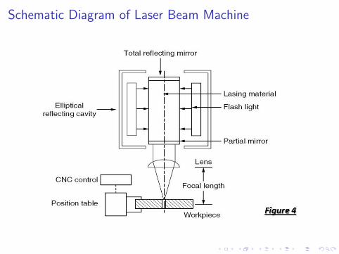
Schematic Diagram of Laser Beam Machine

-

Principle of LASER
I The electrons at ground state can be excited to higher stateof energy by absorbing energy form external sources likeelectronic vibration at elevated temperature, through chemicalreaction or by absorbing photons.
I On reaching the higher energy level, the electron reaches anunstable energy band. And it comes back to its ground statewithin a very small time by releasing a photon. This is calledspontaneous emission.
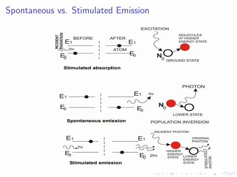
Spontaneous vs. Stimulated Emission

Working of LASER

LASER beam and depth of focus
I (r) = I0exp
(−8r2
w2
)(1)
where I0 is the maximum intensity, r is defined as the distancefrom the center of the beam in gaussian distribution of laser beam,and w(minimum spot or gaussian beam diameter) is the diameterat which the Intensity is 1/e2 of its maximum value.

Types of LASERS

Light Spectrum

Machining with long pulse lasers and short pulse laser
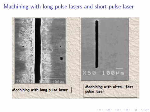
Machining with long pulse lasers and short pulse laser

Laser Material Interaction

Process characteristics
Geometry of a drilled hole using LBM process
tan
(α
2
)=
(e − c)
2d(2)

Power Density and MRR in LBMI The input and focus of LBM are converted to thermal energy
to vaporize the work piece material. The size of the spotdiameter ds is determined by
ds = Flθ (3)
I where Fl is the focal length of lens and θ is the beamdivergence angle (rad).The area of the laser beam at focalpoint, As , is
As =π
4(Flθ)2 (4)

Power Density and MRR in LBM
I The power of the laser beam, Lp, is given by
Lp = Es/∆t (5)
I where Es is the laser energy (in the unit of J) and ∆t is thepulse duration of the laser.
I The power density of the laser beam, Pd (in the unit ofW/mm2), is given by
Pd =LpAs
=4Lp
π(Flθ)2(6)

Power Density and MRR in LBM
I The drilling feed rate f (in the unit of mm/s) can be describedas follows:
f =ClLpEvAs
=ClPd
Ev(7)
I where the conversion efficiency Cl is a constant depending onthe material and conversion efficiency and Ev is vaporizationenergy of the work piece material (J/mm3).
I The MRR can be calculated as follows:
MRR = fAs =ClLpEv
(8)

Parametric Analysis:Cutting front vs cutting speed

Parametric Analysis:Laser Cutting

Parametric Analysis

LASER applications

LASER applications
-

-

...........
Thank You

Electrochemical Machining
Prof. J. Ramkumar
Department of Mechanical EngineeringIIT Kanpur
March 26, 2018

Electrochemical Machining: Products

Electrochemical Machining
I Electrochemical machining is one of the most unconventionalmachining processes.
I The process is actually the reverse of electroplating with somemodifications.
I It is based on the principle of electrolysis.
I In a metal, electricity is conducted by free electrons but in asolution the conduction of electricity is achieved through themovement of ions.
I Thus the flow of current through an electrolyte is alwaysaccompanied by the movement of matter.
I In the ECM process the work-piece is connected to a positiveelectrode and the tool to the negative terminal for metalremoval.

Electrochemical Machining contd.

Electrochemical Machining contd.

Electrochemical Reactions
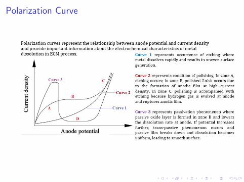
Polarization Curve

Electrical Double Layer

Over Potential in ECM

Electrochemistry of ECM process
I The electrolysis process is governed by the following twolaws proposed by Faraday
• The amount of chemical change produced by an electriccurrent, that is, the amount of any material dissolved ordeposited, is proportional to the quantity of electricity passed.
• The amounts of different substances dissolved or deposited bythe same quantity of electricity are proportional to theirchemical equivalent weights.
m ∝ ItE (1)
where m is the mass of dissolved metal, I is the current, t istime and E is the gram chemical equivalent (E = A/Z ), A isthe atomic mass of anode and Z is the valency of dissolutionof anode
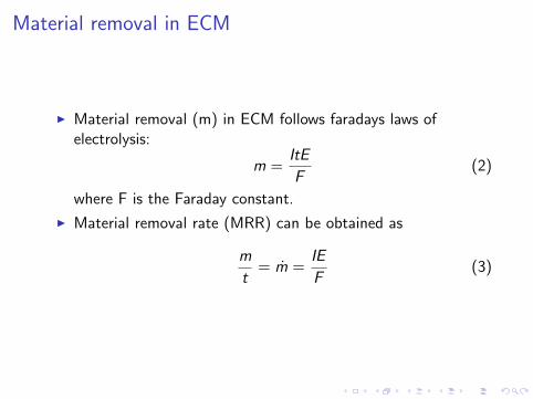
Material removal in ECM
I Material removal (m) in ECM follows faradays laws ofelectrolysis:
m =ItE
F(2)
where F is the Faraday constant.
I Material removal rate (MRR) can be obtained as
m
t= m =
IE
F(3)

Material removal in ECM
I MRR can be obtained as
ρavat
=ρaAaya
t=
IE
F(4)
I MRRl (linear material removal rate) is obtained as
MRRl =yat
=IE
FρaAa(5)
where, ρa is the density of anode, va = volume of materialremoved from the anode in time t, Aa = cross-sectional areaon the anode from which material is being removed in time t,ya is the thickness of material removed in time t.

Linear material removal rate in ECM
As J = I/Aa(current density),
MRRl =yat
=JE
Fρa(6)
As (V −∆V ) is the voltage available for driving current throughthe electrolyte. so, the current density can be expressed as
J =I
Aa=
(V −∆V )
RAa=
(V −∆V )y
kAaAa
= k(V −∆V )
y(7)
So, the MRRl can be written as
MRRl =
(V −∆V
Aa
)(kAa
y
)E
Fρa(8)
Where ∆V is over potential, k = electrolyte’s electricalconductivity

Applications of ECM
I Die sinking
I Profiling and contouring
I Trepanning
I Grinding, Drilling and Micro-machining

Applications of ECM contd.

...........
Thank You