cable accessories · cable termination, ... earthing kit for cable terminations, jsa 4 – 6, jxt 1...
TRANSCRIPT

1
Cable Accessories 7.2 – 42 kV
nkt.com

2
Table of content
Cable AccessoriesCable Accessories 7.2 – 42 kV .............................................................................................................. 4Our five core competencies ................................................................................................................... 5Requirements and approvals ................................................................................................................ 6Reasons for choosing NKT Cable Accessories ................................................................................ 7 – 8Cable Accessories 7.2 – 42 kV ............................................................................................................... 9
Cable Accessories 7.2 – 42 kVCable jointsCable joint with cold shrink outer jacket, SOJ CS, SOJ CSS 12 – 24 kV .............................................. 11Cable joint for radially watertightened cable, SOJ CSWS, SOJ RWI, SOJ RWIT 12 – 24 kV ................ 12Cable joint with or without outer jacket, SOJ SL, SOJ R 12 – 24 kV ..................................................... 13Cable joint with heat-shrink outer jacket, SOJ HSTS 12 – 36 kV .......................................................... 14Cable joint, for cables with Cu-tape screen, SOJ EA 12 – 24 kV .......................................................... 16Tape cable joint, SMXB 12 – 36 kV ....................................................................................................... 20
Cable cabinetsCable cabinet, 12 – 24 kV, 250 A ......................................................................................................... 22Cable cabinet, 12 – 36 kV, 630 A .......................................................................................................... 24
Cable connectors and shrouded terminationsScreened separable cable connectors, CSE-A 12 – 24 kV, 250 A ........................................................ 26Screened separable cable connectors, CSE-A 12 – 42 kV, 400 A ....................................................... 29Screened separable cable connectors, CSE-A 12 – 42 kV, 630 A ........................................................ 31Screened separable connectors for cables with Cu-tape screen, CSE-A 12 – 36 kV, 630 A .............. 32Parallel connectors, CSEP-A 12 – 42 kV, 630 A .................................................................................. 34Parallel connectors for cables with Cu-tape screen, CSEP-A 12 – 24 kV, 630 A ................................. 35Surge arresters for 630 A connectors, CSAP-A, 12 – 24 kV, 630 A ...................................................... 37Shrouded termination, TB-A 12 kV, 630 A .......................................................................................... 38Shrouded termination, KAP 630, 12 – 24 kV, 630 A ............................................................................. 39Shrouded termination, KAP 300 U, 12 – 24 kV, 300 A .......................................................................... 41
Cable terminationsDimensional drawings, SOT ................................................................................................................. 42Premolded cable termination, indoor, SOT 7.2 kV .............................................................................. 43Premolded cable termination, complete kits, SOT SCL 12 – 36 kV ..................................................... 44Premolded cable termination, SOT 12 – 36 kV .................................................................................... 45Cable termination for cables with Cu-tape screen, SOT 12 – 36 kV .................................................... 46Cable termination, recommended to be used in applications weresignificant harmonics may occur, indoors, APIT 12 – 36 kV ................................................................ 49Cable termination, recommended to be used in applications weresignificant harmonics may occur, outdoors, APSEA 12 – 36 kV .......................................................... 50Cable termination, outdoor, APED 12 – 36 kV ...................................................................................... 52

3
We reserve the right to make technical changes or modify the content
Cable AccessoriesCable Accessories 7.2 – 42 kV .............................................................................................................. 4Our five core competencies ................................................................................................................... 5Requirements and approvals ................................................................................................................ 6Reasons for choosing NKT Cable Accessories ................................................................................ 7 – 8Cable Accessories 7.2 – 42 kV ............................................................................................................... 9
Cable Accessories 7.2 – 42 kVCable jointsCable joint with cold shrink outer jacket, SOJ CS, SOJ CSS 12 – 24 kV .............................................. 11Cable joint for radially watertightened cable, SOJ CSWS, SOJ RWI, SOJ RWIT 12 – 24 kV ................ 12Cable joint with or without outer jacket, SOJ SL, SOJ R 12 – 24 kV ..................................................... 13Cable joint with heat-shrink outer jacket, SOJ HSTS 12 – 36 kV .......................................................... 14Cable joint, for cables with Cu-tape screen, SOJ EA 12 – 24 kV .......................................................... 16Tape cable joint, SMXB 12 – 36 kV ....................................................................................................... 20
Cable cabinetsCable cabinet, 12 – 24 kV, 250 A ......................................................................................................... 22Cable cabinet, 12 – 36 kV, 630 A .......................................................................................................... 24
Cable connectors and shrouded terminationsScreened separable cable connectors, CSE-A 12 – 24 kV, 250 A ........................................................ 26Screened separable cable connectors, CSE-A 12 – 42 kV, 400 A ....................................................... 29Screened separable cable connectors, CSE-A 12 – 42 kV, 630 A ........................................................ 31Screened separable connectors for cables with Cu-tape screen, CSE-A 12 – 36 kV, 630 A .............. 32Parallel connectors, CSEP-A 12 – 42 kV, 630 A .................................................................................. 34Parallel connectors for cables with Cu-tape screen, CSEP-A 12 – 24 kV, 630 A ................................. 35Surge arresters for 630 A connectors, CSAP-A, 12 – 24 kV, 630 A ...................................................... 37Shrouded termination, TB-A 12 kV, 630 A .......................................................................................... 38Shrouded termination, KAP 630, 12 – 24 kV, 630 A ............................................................................. 39Shrouded termination, KAP 300 U, 12 – 24 kV, 300 A .......................................................................... 41
Cable terminationsDimensional drawings, SOT ................................................................................................................. 42Premolded cable termination, indoor, SOT 7.2 kV .............................................................................. 43Premolded cable termination, complete kits, SOT SCL 12 – 36 kV ..................................................... 44Premolded cable termination, SOT 12 – 36 kV .................................................................................... 45Cable termination for cables with Cu-tape screen, SOT 12 – 36 kV .................................................... 46Cable termination, recommended to be used in applications weresignificant harmonics may occur, indoors, APIT 12 – 36 kV ................................................................ 49Cable termination, recommended to be used in applications weresignificant harmonics may occur, outdoors, APSEA 12 – 36 kV .......................................................... 50Cable termination, outdoor, APED 12 – 36 kV ...................................................................................... 52
AccessoriesScreen separation kit for 3-core cables, PSSK, PSSK L, PSSK E ...................................................... 54Branch seal kit for 3-core cable terminations, TSH, SSH ................................................................... 55Earthing kit for cable terminations, JSA 4 – 6, JXT 1 – 3 ..................................................................... 56Screen connection for cable joints, JSA 10 – 16 .................................................................................. 57Armouring kit for cable joints, ARM .................................................................................................... 58Cable connection, cverhead line clamps, FK, FKFB ........................................................................... 59Cable connection, cable lugs, SCL-B ................................................................................................. 60Cable connection, cable connectors, SC-B ....................................................................................... 60Cable connection, cable connectors, SH-SKRM ................................................................................ 60Accessories, bird protection, HU, HUF, HUS ....................................................................................... 61
General accessories and toolsAccessories, tapes ............................................................................................................................. 62Other accessories ............................................................................................................................... 63Tools ................................................................................................................................................... 64
Universal clampsUKR 90, UKRA 90 ............................................................................................................................... 68UKR 200, UKRA 200 ............................................................................................................................ 69Typical applications, UKR 200,UKRA 200 ........................................................................................... 70
List of content – Alphabetical orderList of content – Alphabetical order ......................................................................................................72
List of content – by categoryList of content by category ...................................................................................................................75

4
Cable Accessories factory and Technical Lead Center situated in Alingsås, Sweden.
Cable Accessories7.2 – 42 kV
We work to create safe electrical distribution via power cable networks. To achieve this, we develop, manufacture and market a broad range of cable accessories, for distribution and trans- mission.
Our main customers are utilities, EPC and OEM.Our core competencies are electrical connections in cable systems and manage electric field grading systems. Our own test laboratories are essential for our product developement and quality assur-ance.
CatalogThis catalog covers cable accessories in the range from 7.2 to 42 kV.
List of content sorted by name or product category can be found in the end of this catalog. The product catalog can also be downloaded from our website.
Other product catalogs available on request: Cable Accessories ≤ 1 kV, XLPE cables Cable Accessories 12 – 52 kV, PILC cables Cable Accessories 52 – 420 kV, XLPE cables
We reserve the right to alter the design and range of our products without prior notice.
Our business idea“We provide companies that work with electric power with solutions which enable them to joint and connect cables easily and safely, and distribute electricity.”
Satisfying customer needs, Quality and Environment are our priorities.
We work continuously to improve our processes. Important foundations for this work are our quality and environment management systems.
ISO 9001 ISO 14001 OHSAS 18001
NKT HV Cables AB Sävelundsgatan 2441 38 AlingsåsSweden

5
1. Understanding the total cost and value for cable accessories as elements in systems
We as supplier of components that are pieces in a puzzle, the cable system and the related interfaces, need to understand the demand and requirements on the single component in order to optimize the value and performance. The value offer for components is in relation-ship with the system, we also add value in later stages in this value chain. By knowing the actual expectations and trends we are able to meet the demand in the long term. Our expertise and extensive global footprint ensure we understand the product requirements and future trends.
2. Manufacturing and quality assurance of insulation system based on rubber
With modern manufacturing technology and quality management processes we can keep up the productivity and thereby offer competitive products. We have material expertise as well as test facilities for rubber material develop-ment and improvements, by both know-how and know-why we are able deliver insulation systems in the complete range of cable accessories.
3. Workmanship in installation of cable accessories
Joints and terminations are regarded as critical components in cable systems, and the work-manship during installation is very important when considering the risk of future failures. When preparing cable several layers need to
be removed or treated without damaging other layers, this requires skills and knowledge how to handle tools for this application. Knowledge about what are the critical steps in accessories assembling gives the best foundation for successful and safe installation.
4. Electrical, mechanical and thermal de-sign of insulation systems and connectors
The design of our accessories are based on ex-pertise within electrical, mechanical and thermal performance. It is essential to understand the connection between them since all the three technologies comes down to one parameter namely coupled electrical, mechanical and ther-mal properties. We have long extensive experi-ence and use modern FEM software that allows us to calculate coupled electrical and thermal fields as well as thermomechanical conditions. Our electrical designs involves geometrical, resistive and refractive field controlling involving advanced field grading rubber materials.
5. Performance of rubber and metal materials in outdoor conditions
Cable accessories are exposed to harsh outdoor climate conditions. Insulators are exposed to UV radiation and pollution, joints are operating underground often in wet conditions, and they shall perform for many years without breakdown. It is essential for us to keep up the expertise within outdoor insulation performance and corrosion protection, with expertise and our test facilities, e.g. Weather-O-Meter test, we can ensure the product deliver what we promise.
Our five core competencies
1
4
2
5
3

6
Definition of voltagesCables and cable accessories are classified according to the voltages at which they operate. A rapid survey at standards all over the world shows that the designations are slightly different. However, IEC designations gives a clear picture of used vocabulary. The voltages normally used in this context are:
U0 = the rated r.m.s.(root mean square) power- frequency voltage between each conductor and screen or sheath for which cables and accessories are designed.
U = the rated r.m.s power-frequency voltage between two different conductors for which the cables and accessories are designed.
Um = the maximum r.m.s power-frequency voltage between two different conductors for which the cables and accessories are designed. It is the highest voltage that can be sustained under normal operating conditions at any time and at any point in a system. It excludes temporary voltage variations due to fault conditions and the sudden disconnection of large loads.
StandardsElectrical components must meet numerous requirements in areas such as functional safety, technical performance, personal safety and so on. For cable accessories, compliance with the quality requirements is checked by type and routine test-ing. We perform these tests to various standards, both international and national.
The standards on which our tests are usually based:IEC(International Electrotechnical Commission) An international standard used worldwide.
EN(European Norm)
HD(Harmonization Document)These standards were developed by CENELEC for the European countries. In most cases, these standards harmonize with IEC standards. Each European country publishes the standard as its own, and there may be some national deviations and special requirements.
Voltage range Um 7.2 – 42 kVIEC: Current standards are IEC 61442, which
covers test methods, and IEC 60502-4, which sets out the testing requirements.
IEC contains Um ≤ 36 kVCENELEC: Current standards are EN 61442 which covers test methods and is identical to IEC 61442.
HD 629.1 S2, which sets out the testing require-ments. The main difference between IEC and CENELEC is that CENELEC stipulates a longer period of temperature cycling under voltage.
HD 629.2 S1 applies to accessories for paper- insulated cables and transition joints. A test conducted in accordance with CENELEC also satisfies the IEC requirements. To include the less common voltages which occur in certain European countries, CENELEC has included more voltage classes than IEC. In addition, CENELEC runs up to Um42 kV.
Requirements and approvals
CENELEC voltage classes
U0 U Um
3.6 6 7.2
3.8 6.6 7.2
6 10 12
6.35 11 12
8.7 15 17.5
12 20 24
12.7 22 24
18 30 36
19 33 36
20.8 36 42

7
A power cable network must be capable of supplying electric power without interruption. If a failure does occur, it is usually the junction points in the network that are at fault, rarely the cable. So it pays to choose cable accessories with care.
One reason for our success is that we have constantly developed cable accessories for all types of cables. This has given us both broad and deep experience base. We have also developed our accessories to manage optical fiber in power cables, and integrated screen separation in cable joints. This enables system designers to improve and optimize their systems.
Our products are made with modular design, this makes the accessories exeptionally easy to install. The jointers can easily become familiar with the components, and this reduces the risk of mistakes.
Another advantage is that our cable terminations can be assembled on the ground with controlled conditions and then lifted into place – simple and safe!
Unless otherwise specified, the cable accessories are supplied as standard with bolt connections for conductors.
ExperienceLong experience brings great expertise. We have been manufacturing cable accessories for paper-insulated cables for about 100 years. When XLPE-insulated cables were introduced more than 50 years ago, we were involved from the outset. Since then we have been in the forefront of development. We have a long experience in high voltage engineering and have always led the field in research and development.
Reasons for choosing NKT Cable Accessories
Manufacturing outdoor cable termination forpaper-insulated cables in 1962.

8
Research and DevelopmentOur core competence is our expertise in electricalconnections in power cable systems. Successful product development requires proper resources. We have an advanced chemistry laboratory, a profound expertise in the field of polymers and well-equipped high voltage and high-current laboratories.
Our corporate research Centers enables us to con-duct long term developement of new technologies.
Better EconomyNKT Cable Accessories provide greater safety. This means major savings in the long term, as well as lower costs from simplified routines for pur-chase, delivery and storage.
Also shorter installation time reduces the total cost for the system.
Professional TrainingThe technology of cables and their installation is constantly developing. We offer a broad range of courses in cable technology and cable accesso-ries. Our instructors are involved in our develop-ment projects, so you can be sure that they have access to the latest technology.
We arrange training programmes and practical exercises in the assembly of cable accessories up to 420 kV. All course participants will receive a diploma or a training certificate after successfully passing theoretical and practical tests.
We facilitate the training in our factory or we may arrange in suitable location in agreement with you.
If you would like to know more about the courses, please contact your NKT representative or our training department directly.
Reasons for choosing NKT Cable Accessories

9
NKT cable accessories for 7.2 – 42 kV are characterized by simple solutions with a reliable function. Long experience and continuous product development enable us to offer products that meet future requirements for reliable and dependable systems.
At the time when XLPE-insulated cable was introduced in the beginning of the 1960s, we already realized the importance of the cable accessories having a constant, active pressure over the cable, in this way following the physical changes in the cable in service. The solution at the time was to use tapes with different properties. Our patented field-control material and the first premolded products were introduced in the 1970s. The technology has since been a guiding force for our product development.
Our current range includes cable joints, cable terminations and screened separable cable connectors in line with this concept.
The fact that the products are premolded means that they are manufactured in a single piece including important functions such as electrical field-control, insulation and sealing.
The use of flexible materials enables the cable accessory to follow the variations in the cable under load, thus ensuring an active pressure for a reliable power transmission.
Manufacturing the products from soft rubber also means that fewer sizes covers different cable dimensions. All of this, in combination with the bolt technology that we use in our cable connectors and cable lugs, gives a reliable and dependable system.
More than one million premolded cable joints, cable terminations and cable connectors have already been installed by customers in electricity distribution networks all over the world. Our cable terminations and screened separable cable connectors are also purchased by customers who manufacture switchgears and other installations.
In addition to the products presented in this catalogue, we offer especially adapted products and solutions for different markets and cables and a range of cable preparation tools. Please do not hesitate to contact us if you have any other needs or queries.
Cable Accessories7.2 – 42 kV
Cable accessories with four important functions: grading of electricalfields, withstanding creepage currents, moisture barriers and mechanical protection.

10

11
Premolded cable joint with cold shrink outer jacket
SOJ 12 – 24 kV
UsePremolded cable joint for XLPE- and EPR-insulated 1- or 3-core cables with Al or Cu conductor, 12 – 24 kV.
Standards CENELEC, HD 629.1 S1 SS 424 14 45 Edition 1 VDE 0278 KEMA S8 IEEE 404 1993
DesignThe joint body is made of rubber in three layers: a conductiveouter layer, an insulating layer and a conductive inner layer.The kit contains all mounting material.
The joint body is pre-expanded on plastic inserts beforeinstallation. When the cables have been connected and the
joint is centred, the inserts are pulled out. This way the jointbody will provide an active pressure on the cable insulationand will follow variations in the cable during load.
The kits are selected as follows:SOJ CSSContains cold-shrink outer jacket and connectors withshear-off bolts for conductor and screen.
SOJ CSContains cold-shrink outer jacket. Connectors are notincluded.
Note: For 16 – 35 mm2 cables ADAPTER must be ordered
separately, see following pages. WIM 3 to be used as complement when jointing
3-core watertightened cable, see following pages.
Always select products by Insulation diameter.
Insulationdiameter
Cable cross section Designation CSS CS Designation CSS CS12 kV 24 kV 1-core Weight Weight 3-core Weight Weight
mm mm2 kg/kit kg/kit kg/kit kg/kit
15–19.5 50–70 – SOJ 121-1 2.5 2.4 SOJ 121–3 5.0 4.7
18.5–24 95–150 – SOJ 122-1 2.6 2.5 SOJ 122-3 5.5 5.2
23–28 185–240 – SOJ 123-1 3.4 3.2 SOJ 123-3 7.0 6.2
27–34 300–400 – SOJ 124-1 4.7 4.2 SOJ 124-3 – 7.3
33.5-46 500–630 – SOJ 125-1 5.5 4.8 – – –
19–23.5 – 50–70 SOJ 241-1 3.3 3.2 SOJ 241–3 5.8 5.5
22.5–28 – 95–150 SOJ 242-1 3.6 3.5 SOJ 242-3 6.9 6.5
27–35 – 185–240 SOJ 243-1 4.3 4.0 SOJ 243-3 8.8 8.0
27–35 – 300 – 4.5 4.0 – – –
33.5-46 – 400 SOJ 244-1 5.3 4.8 – – –
33.5-46 – 500–630 – 5.5 4.8 – – –
Accessories Use SOJ CSS SOJ CS See page
ADAPTER Cables with different dimensions X X 17
TS Additional kit for sector shaped 3-core cables X X 17
WIM 3 Diffusion seal X X 18
SH-SKRM Bolt connector – X 60
JSA 10–13 Cables with Cu-tape screen X X 57
JSA 14–16 Cables with Al-foil screen X X 57
D
ADAPTER
WIM SH-SKRM
TS
SOJ CSS
Accessories, to be ordered separately

12
Premolded cable joint for radially watertightened cable
SOJ 12 – 24 kV
UsePremolded cable joint for XLPE- and EPR-insulated 1- or 3-core cables with Al- or Cu-conductor and radially watertightened aluminium foil for 12 – 24 kV.
StandardsMeets the requirements of: CENELEC, HD 629.1 S1 SS 424 14 45 edition 1 VDE 0278 KEMA S8 IEEE 404 1993
DesignThe joint body is made of rubber in three layers: a conductiveouter layer, an insulating layer and a conductive inner layer.The kit contains all mounting material.
The joint body is pre-expanded on plastic inserts beforeinstallation. When the cables have been connected and thejoint is centred, the inserts are pulled out. This way the jointbody will provide an active pressure on the cable insulationand will follow variations in the cable during load.
The kits are selected as follows:SOJ CSWSUsed for jointing watertightened 1-core cables with Cu-wirescreen. Contains cold-shrink outer jacket, Al-foil tube andconnectors for conductor and screen.
SOJ RWIUsed for jointing three 1-core cables, Prysmian typeWISKITM or similar. Contains copper braids to connectscreens, Al foil tubes for radially watertightness and alsoouter jacket RULLE. Connectors and items for jointing ofseparate earth wire are not included.
SOJ RWITUsed for jointing three 1-core cables Prysmian typeWISKITM or similar, to a standard 3-core cable. Containscopper braids to connect screens, STOP longitudinalwatertightness and outer jacket RULLE. Connectors andarticles for jointing a separate earth wire are not included.
Note: For 16 – 35 mm2 cables, ADAPTER must be ordered
separately, see the table below.
Insulationdiameter
Cable cross section Designation CSWS Designation RWI RWIT12 kV 24 kV 1-core Weight 3 x 1-core Weight Weight
mm mm2 kg/kit kg/kit kg/kit
15–19.5 50–70 – SOJ 121-1 50 3.0 SOJ 121-31 7.3 5.0
18.5–24 95–150 – SOJ 122-1 95 150 3.2 SOJ 122-31 7.9 5.5
23–28 185–240 – SOJ 123-1 240 4.0 SOJ 123-31 10.3 7.0
27–34 300–400 – SOJ 124-1 400 5.3 – – –
33.5–46 500–630 – SOJ 125-1 630 6.1 – – –
19–23.5 – 50–70 SOJ 241-1 50 3.9 SOJ 241-31 10.0 5.5
22.5–28 – 95–150 SOJ 242-1 95 150 4.2 SOJ 242-31 10.9 6.5
27–35 – 185–240 SOJ 243-1 240 4.9 SOJ 243-31 13.0 8.0
33.5–46 – 300–400 SOJ 244-1 400 5.9 – – –
33.5–46 – 500–630 SOJ 244-1 630 6.1 – – –
Accessories Use SOJ CSWS SOJ RWI SOJ RWIT See page
ADAPTER Adapter kit for cables with different dimensions X X X 17
TS Additional kit for sector shaped cables – X X 17
SH-SKRM Bolt connector – X X 60
D
ADAPTER
SH-SKRM
TS
SOJ RWIT
SOJ CSWS
SOJ RWI
Always select products by Insulation diameter.
Accessories, to be ordered separately

13
Premolded cable joint with or without outer jacket, RULLE
SOJ 12 – 24 kV
UsePremolded cable joint for XLPE- and EPR-insulated 1- or 3-core cables with Al or Cu conductor for 12 – 24 kV.
StandardsMeets the requirements of: CENELEC, HD 629.1 S1 SS 424 14 45 edition1 VDE 0278 KEMA S8 IEEE 404 1993
DesignThe joint body is made of rubber in three layers: a conductive outer layer, an insulating layer and a conductive inner layer.
The joint body is pre-expanded on plastic inserts beforeinstallation. When the cables have been connected and the
joint is centred, the inserts are pulled out. This way the jointbody will provide an active pressure on the cable insulationand will follow variations in the cable during load.
The kits are selected as follows:SOJ R Contains outer jacket RULLE; a two-layer tape of EPDM-
rubber and mastic, which is wrapped around the joint. Connectors are not included.
SOJ SL Supplied without outer jacket. An outer jacket approved
by NKT must be added, for example type ARM. Connectors are not included.
Note: For 16 – 35 mm2 cables ADAPTER must be ordered
separately, see the table below. WIM 3 / WIM 4 – used as complement when jointing
3-core watertightened cable, see the table below.
Always select products by Insulation diameter.
Insulationdiameter
Cable cross section Designation R Designation SL Designation R Designation SL12 kV 24 kV 1-core Weight 1-core Weight 3-core Weight 3-core Weight
mm mm2 kg/kit kg/kit kg/kit kg/kit
15–19.5 50–70 – SOJ 121-1 R 2.6 SOJ 121-1 SL 1.0 SOJ 121-3 R 4.7 SOJ 121-3 SL 2.0
18.5–24 95–150 – SOJ 122-1 R 3.0 SOJ 122-1 SL 1.1 SOJ 122-3 R 5.6 SOJ 122-3 SL 2.3
23–28 185–240 – SOJ 123-1 R 3.1 SOJ 123-1 SL 1.2 SOJ 123-3 R 6.4 SOJ 123-3 SL 2.7
27–34 300–400 – SOJ 124-1 R 4.3 SOJ 124-1 SL 1.6 SOJ 124-3 R 8.9 SOJ 124-3 SL 4.2
33.5–46 500–630 – SOJ 125-1 R 5.9 SOJ 125-1 SL 2.2 – – – –
19–23.5 – 50–70 SOJ 241-1 R 3.2 SOJ 241-1 SL 1.3 SOJ 241-3 R 6.2 SOJ 241-3 SL 2.8
22.5–28 – 95–150 SOJ 242-1 R 3.9 SOJ 242-1 SL 1.5 SOJ 242-3 R 7.0 SOJ 242-3 SL 3.4
27–35 – 185–300 SOJ 243-1 R 4.5 SOJ 243-1 SL 1.8 SOJ 243-3 R 9.1 SOJ 243-3 SL 4.5
33.5–46 – 400 SOJ 244-1 R 6.4 SOJ 244-1 SL 2.2 – – – –
Accessories Use SOJ R SOJ SL See page
ADAPTER Cables with different dimensions X X 17
JSA 10–13 Cables with Cu-tape screen X X 57
JSA 14–16 Cables with Al-foil screen X X 57
TS Additional kit for sector shaped 3-core cables X X 17
WIM Diffusion seal X X 18
ARM Armouring kit – X 58
STOP Crutch seal when 3 x 1-core cables are jointed to a 3-core X – 17
SH-SKRM Bolt connector X X 60
D
ADAPTER
WIM STOP
SH-SKRM
TS
SOJ R
Accessories, to be ordered separately

14
Premolded cable joint with heat-shrink outer jacket
SOJ HSTS 12 – 24 kV
UsePremolded cable joint with heat-shrink outer jacket and boltconnector. For jointing 12 – 24 kV XLPE- and EPR-insulated1- or 3-core cables with Al- or Cu-conductors.
StandardsMeets the requirements of: SS 424 14 45 edition 1 VDE 0278 CENELEC, HD 629.1 S1 KEMA S8 IEEE 404 1993
DesignThe joint body is made of rubber in three layers:a conductive inner layer, an insulating layer and a conductiveouter layer. The joint kit is complete and restores all the parts of the cable.
The joint body is pre-expanded on plastic inserts beforeinstallation. When the cables have been connected and the joint is centred, the inserts are pulled out. This way the joint body will provide an active pressure on the cable insulation and will follow variations in the cable during load.
The kits include: Heat-shrink outer jacket, vulcanizing tape and connectors
with shear-off bolts for conductor and screen.
Note: Branch seal kit CSK 2, CSK 3 for transition between 3- or
1-core cables. Kits include a branch seal in heatshrink material, tapes and an installation instructure. CSK is to be ordered separately according to the table.
For 16 – 35 mm2 cables ADAPTER must be ordered separately, see the table below.
WIM 3 – used as complement when jointing watertightened cable, see the table below.
Always select products by Insulation diameter.
Voltage Insulationdiameter
Conductorcross section
Designation Weight
kV mm mm2 kg/kit
Cable joint for 1-core
12 15–19.5 50–70 SOJ 121-1 70 HSTS 2.5
12 18.5–24 95–150 SOJ 122-1 150 HSTS 2.6
12 23–28 185–240 SOJ 123-1 240 HSTS 3.4
12 27–34 300–400 SOJ 124-1 400 HSTS 4.7
12 33.5–46 500–630 SOJ 125-1 630 HSTS 5.5
Cable joint for 3-core
12 15–19.5 50–70 SOJ 121-3 70 HSTS 5.0
12 18.5–24 95–150 SOJ 122-3 150 HSTS 5.5
12 23–28 185–240 SOJ 123-3 240 HSTS 7.0
12 27–34 300–400 SOJ 124-3 400 HSTS 9.1
Cable joint for 1-core
24 19–23.5 50–70 SOJ 241-1 70 HSTS 3.3
24 22.5–28 95–150 SOJ 242-1 150 HSTS 3.6
24 27–35 185–240 SOJ 243-1 240 HSTS 4.3
24 27–35 300 SOJ 243-1 300 HSTS 4.5
24 33.5–46 400 SOJ 244-1 400 HSTS 5.3
24 33.5–46 500–630 SOJ 245-1 630 HSTS 5.5
Cable joint for 3-core
24 19–23.5 50–70 SOJ 241-3 70 HSTS 5.8
24 22.5–28 95–150 SOJ 242-3 150 HSTS 6.9
24 27–35 185–240 SOJ 243-3 240 HSTS 8.8
Accessories Use See page
CSK Branch seal for transition between 3- and 1-cor cables 18
ADAPTER Cables with different dimensions 17
WIM 3 Diffusion seal 18
JSA 10–13 Cables with Cu-tape screen 57
JSA 14–16 Cables with Al-foil screen 57
SOJ HSTS 3-CORE KIT
ADAPTER WIMCSK
Accessories, to be ordered separately

15
Premolded cable joint with heat-shrink outer jacket
SOJ HSTS 36 kV
UsePremolded cable joint with heat-shrink outer jacket and bolt connector. For jointing 36 kV XLPE- and EPR-insulated1- or 3-core cables with Al or Cu conductors.
DesignThe joint body is made of rubber in three layers:a conductive inner layer, an insulating layer and a conductive outer layer. The joint kit is complete and restores all the parts of the cable.
The joint body is pre-expanded on plastic inserts before installation. When the cables have been connected and the joint is centred, the inserts are pulled out. This way the joint body will provide an active pressure on the cable insulation and will follow variations in the cable during load.
The kits are included: Heat-shrink outer jacket, vulcanizing tape and connectors
with shear-off bolts for conductor and screen.
Note: Branch seal kit CSK 2, CSK 3 for transition between 3- or
1-core cables. Kits include a branch seal in heat-shrink material, tapes and an installation instructure. CSK is to be ordered separately according to the table.
For 16 – 35 mm2 cables ADAPTER must be ordered separately, see the table below.
WIM 3 – used as complement when jointing watertightened cable, see the table below.
Always select products by Insulation diameter.
Voltage Insulationdiameter
Conductorcross section
Designation Weight
kV mm mm2 kg/kit
Cable joint for 1-core
36 19–23.5 50–70 SOJ 361-1 70 HSTS 3.3
36 22.5–28 50–70 SOJ 362-1 70 HSTS 3.6
36 22.5–28 95 SOJ 362-1 95 HSTS 3.6
36 27–35 95–150 SOJ 363-1 150 HSTS 4.3
36 27–35 185–240 SOJ 363-1 240 HSTS 4.3
36 33.5–46.5 185–240 SOJ 364-1 240 HSTS 5.2
36 33.5–46.5 300–400 SOJ 364-1 400 HSTS 5.3
36 33.5–46.5 500–630 SOJ 365-1 500 HSTS* 5.5
Cable joint for 1-core
36 19–23.5 50–70 SOJ 361-3 70 HSTS 5.8
36 22.5–28 50–70 SOJ 362-3 70 HSTS 6.9
36 22.5–28 95 SOJ 362-3 95 HSTS 6.9
36 27–35 95–150 SOJ 363-3 150 HSTS 8.8
36 27–35 185–240 SOJ 363-3 240 HSTS 8.8
36 33.5–46.5 185–240 SOJ 364-3 240 HSTS 10.6
36 33.5–46.5 300–400 SOJ 364-3 400 HSTS 10.7
36 33.5–46.5 500–630 SOJ 365-3 500 HSTS* 10.9
* Fits to 630 mm2 if insulation diameter is 33.5–46.5.
Accessories Use See page
CSK Branch seal for transition between 3- and 1-cor cables 18
ADAPTER Cables with different dimensions 17
WIM 3 Diffusion seal 18
JSA 10–13 Cables with Cu-tape screen 57
JSA 14–16 Cables with Al-foil screen 57
SOJ HSTS 3-CORE KIT
ADAPTER WIMCSK
Accessories, to be ordered separately

16
Premolded cable joint, for cables with Cu-tape screen
SOJ EA 12 – 24 kV
UsePremolded cable joint for XLPE- and EPR-insulated 1- or 3-core cable with Al or Cu conductors and Cu-tape screen for 12 – 24 kV.
StandardsMeets the requirements of: SS 424 14 45 edition 1 VDE 0278 CENELEC, HD 629.1 S1 KEMA S8 IEEE 404 1993
DesignThe joint body is made of rubber in three layers: a conductiveinner layer, an insulating layer and a conductive outer layer.
The joint body is pre-expanded on plastic inserts beforeinstallation. When the cables have been connected and thejoint is centred, the inserts are pulled out. This way the jointbody will provide an active pressure on the cable insulationand will follow variations in the cable during load.
The kits are selected as follows:SOJ EA Contains copper stockings and constant force springs
to restore the Cu-tape screen and cast resin armouring kit to restore the outer jacket.
Note: Connectors for the cable conductors must be ordered
separately.
Always select products by Insulation diameter.
Insulationdiameter
Cable cross section Designation12 kV 24 kV 1-core
mm mm2
15–19.5 50–70 – SOJ 121–3 EA
18.5–24 95–150 – SOJ 122-3 EA
23–28 185–240 – SOJ 123-3 EA
27–34 300–400 – SOJ 124-3 EA
19–23.5 – 50–70 SOJ 241–3 EA
22.5–28 – 95–150 SOJ 242-3 EA
27–35 – 185–300 SOJ 243-3 EA
Accessories Use See page
ADAPTER Cables with different dimensions 17
TS Additional kit for sector shaped 3-core cables 17
WIM Diffusion seal 18
ARM Armouring kit 58
SH-SKRM Bolt connector 60
D
ADAPTER
WIM SH-SKRM
TS
Accessories, to be ordered separately
17
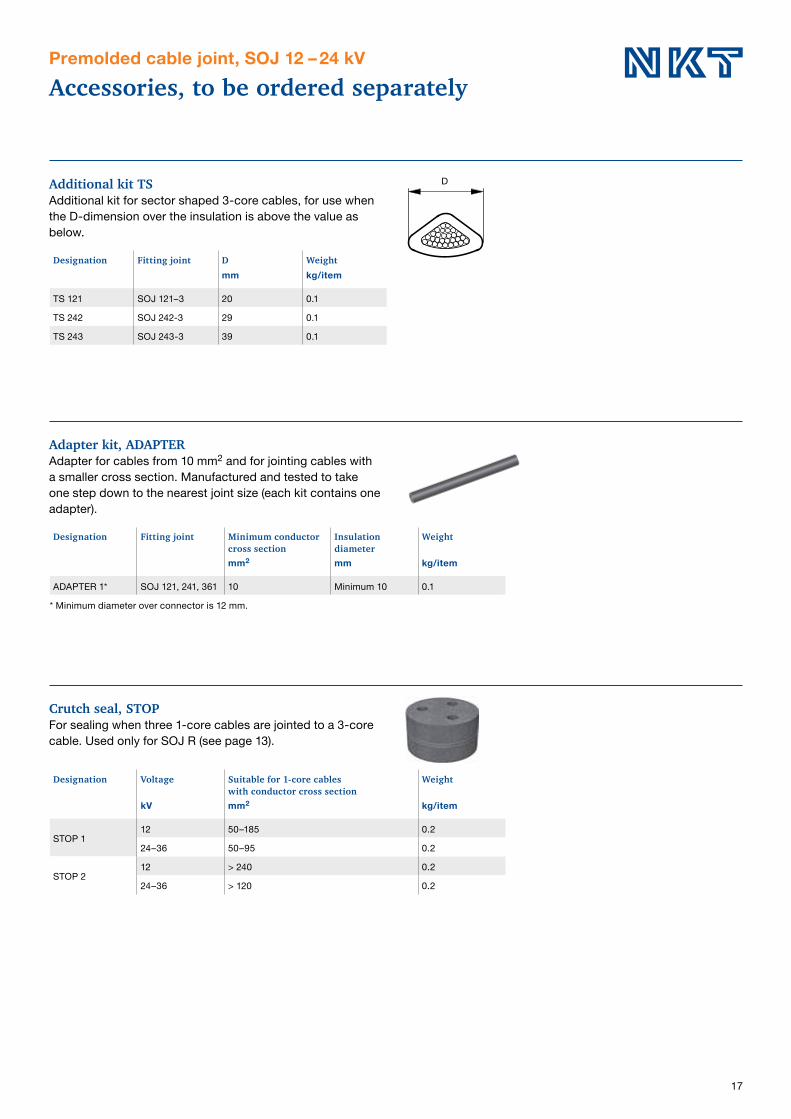
Accessories, to be ordered separatelyPremolded cable joint, SOJ 12 – 24 kV
Additional kit TSAdditional kit for sector shaped 3-core cables, for use when the D-dimension over the insulation is above the value as below.
Adapter kit, ADAPTERAdapter for cables from 10 mm2 and for jointing cables with a smaller cross section. Manufactured and tested to take one step down to the nearest joint size (each kit contains one adapter).
Crutch seal, STOPFor sealing when three 1-core cables are jointed to a 3-core cable. Used only for SOJ R (see page 13).
D
Designation Fitting joint D Weightmm kg/item
TS 121 SOJ 121–3 20 0.1
TS 242 SOJ 242-3 29 0.1
TS 243 SOJ 243-3 39 0.1
Designation Fitting joint Minimum conductorcross section
Insulation diameter
Weight
mm2 mm kg/item
ADAPTER 1* SOJ 121, 241, 361 10 Minimum 10 0.1
* Minimum diameter over connector is 12 mm.
Designation Voltage Suitable for 1-core cableswith conductor cross section
Weight
kV mm2 kg/item
STOP 112 50–185 0.2
24–36 50–95 0.2
STOP 212 > 240 0.2
24–36 > 120 0.2

18
Accessories, to be ordered separatelyPremolded cable joint, SOJ 12 – 36 kV
Diffusion seal, WIMUsed as complement to SOJ CS, SOJ CSS or SOJ R when jointing 1- or 3-core watertightened cables with diffussion barrier of aluminium.
CSKBranch seal kit for , SOJ HSTS when transition between 3- and 1-core cables.
Designation Fitting joint Type of cable Weightkg/kit
WIM 3SOJ 121–3, 122-3, 123-3 SOJ 241–3, 242-3, 243-3 SOJ 361-3, 362-3, 364-3
3-core with Al foil in direct contact with screen 0.3
WIM 5 SOJ 121-1, SOJ 122-1 1-core with Al-foil in direct contact with screen 0.4
WIM 6
SOJ 123-1, SOJ 124-1, SOJ 125-1 SOJ 241-1, SOJ 242-1, SOJ 243-1 SOJ 244-1, SOJ 245-1, SOJ 361-1SOJ 362-1, SOJ 363-1, SOJ 364-1, SOJ 365-1
1-core with Al-foil in direct contact with screen 0.4
Accessories Conductor cross section12 kV 24 kV 36 kVmm2
CSK 2 95–300 50–300 50–95
CSK 3 – – 150–300
WIM 3
CSK
Accessories Description CSS CS R SL RWI RWIT HSTS See page
ADAPTER Cables with different dimensions X X X X X X X 17
TS Additional kit for sector shaped 3-core cables X X X X – X X 17
WIM Diffusion seal X X X – – – X 18
STOP Crutch seal when 3 x 1-core cables are jointed to a 3-core – – X – – – – 17
CSK Branch seal for transition between 3- and 1-core cables – – – – – – X 18
SH-SKRM Bolt connector X X X X X X 60
JSA 10–13 Earthing kit for cable with Cu-tape screen X X X – – – X 57
JSA 14–16 Earthing kit for cable with Al-foil screen only X X X – – – X 57
ARM Armoured cable or when extra mechanical protection is required – – – X – – – 58
D
ADAPTER WIM STOP SH-SKRMTS
Accessories, to be ordered separately
19
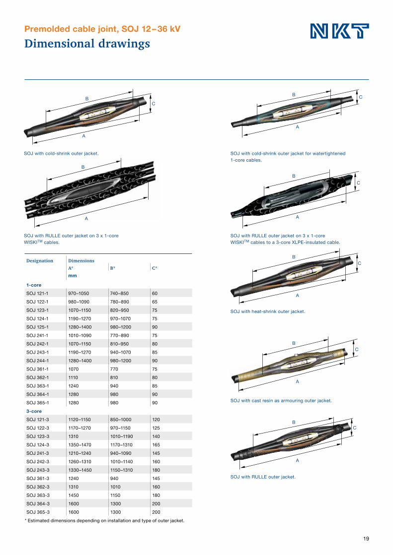
Dimensional drawingsPremolded cable joint, SOJ 12 – 36 kV
Designation DimensionsA* B* C*mm
1-core
SOJ 121-1 970–1050 740–850 60
SOJ 122-1 980–1090 780–890 65
SOJ 123-1 1070–1150 820–950 75
SOJ 124-1 1190–1270 970–1070 75
SOJ 125-1 1280–1400 980–1200 90
SOJ 241-1 1010–1090 770–890 75
SOJ 242-1 1070–1150 810–950 80
SOJ 243-1 1190–1270 940–1070 85
SOJ 244-1 1280–1400 980–1200 90
SOJ 361-1 1070 770 75
SOJ 362-1 1110 810 80
SOJ 363-1 1240 940 85
SOJ 364-1 1280 980 90
SOJ 365-1 1280 980 90
3-core
SOJ 121-3 1120–1150 850–1000 120
SOJ 122-3 1170–1270 970–1150 125
SOJ 123-3 1310 1010–1190 140
SOJ 124-3 1350–1470 1170–1310 165
SOJ 241-3 1210–1240 940–1090 145
SOJ 242-3 1260–1310 1010–1140 160
SOJ 243-3 1330–1450 1150–1310 180
SOJ 361-3 1240 940 145
SOJ 362-3 1310 1010 160
SOJ 363-3 1450 1150 180
SOJ 364-3 1600 1300 200
SOJ 365-3 1600 1300 200
* Estimated dimensions depending on installation and type of outer jacket.
SOJ with cold-shrink outer jacket.
SOJ with RULLE outer jacket on 3 x 1-core WISKITM cables.
SOJ with cold-shrink outer jacket for watertightened 1-core cables.
SOJ with RULLE outer jacket on 3 x 1-core WISKITM cables to a 3-core XLPE-insulated cable.
B
A
C
B
A
C
BC
A
SOJ with heat-shrink outer jacket.
B
A
C
B
A
SOJ with RULLE outer jacket.
SOJ with cast resin as armouring outer jacket.
B
A
C
BC
A

20
Tape cable jointSMXB 12 – 36 kV
UseFor jointing XLPE- and EPR-insulated 1- and 3-core cables with Al or Cu conductor 12 – 36 kV.
StandardMeets the requirements of: SEN 24 14 34 SS 424 14 17 Edition 4 VDE 0278
DesignThe joint kit consists of tapes, stress grading pads FSD and a copper net.
Note: Connectors for conductor and screen and welding
equipment must be ordered separately.
Designation Weight Designation Weight
kg/item kg/item
1 x 3-core or 3 x 1-core cables 1 x 1-core cable
SMXB 1–3 2.6 SMXB 1-1 0.9
SMXB 2-3 3.7 SMXB 2-1 1.1
SMXB 3-3 4.0 SMXB 3-1 1.4
SMXB 4-3 4.3 SMXB 4-1 1.6
SMXB 5-3 4.5 SMXB 5-1 2.0
SMXB 6-3 5.9 SMXB 6-1 2.2
SMXB 7-3 6.7 SMXB 7-1 2.5
SMXB 8-3 9.7 SMXB 8-1 3.6
SMXB 9-3 12.9 SMXB 9-1 5.1
For selecting sizesee next page.
SMXB 10-1 3.8
SMXB 11-1 5.1
SMXB 12-1 6.7
SMXB 13-1 7.8
Accessories Description See page
STOP Crutch seal when 3 x 1-core cables are jointed to a 3-core 17
WIM Diffusion seal 18
SC-B Bolt connector 60
JSA 14-16 Earthing kit for cable with Al-foil screen only 57
JSA 14–16 Cables with Al-foil screen 57
WIM SC-BSTOP
To be ordered separately

21
Tables for selection of tape cable jointSMXB 12 – 36 kV
For compression of aluminium conductors
For compression of Cu-conductors
For termite welding of aluminium or Cu-conductors
Voltage Insulation thickness Cross section mm2
kV mm 10 25 35 50 70 95 120 150 185 240 300 400 500 630 800 1000 1200
One 3-core or three 1-core cables Cable joint SMXB No.
12 3.4 1 1 1 1 1 2 2 2 3 3 6 7 7 8 9 11* 12*
24 5.5 2 3 4 4 4 5 5 6 6 6 8 8 8 9 9 11* 13*
One 1-core cable Cable joint SMXB No.
36 8.0 – 10 10 10 10 10 10 10 11 11 11 11 11 12 13 13 13
* For 3-core cables choose 3 kits.
Voltage Insulation thickness Cross section mm2
kV mm 25 30 50 70 95 120 150 185 240 300 400 500 630 800 1000 1200
One 3-core or three 1-core cables Cable joint SMXB No.
12 3.4 1 1 1 1 1 1 2 2 3 3 7 7 7 8 8 9
24 5.5 3 3 3 3 3 5 5 5 6 6 7 8 8 9 9 11*
One 1-core cable
36 8.0 10 10 10 10 10 10 10 11 11 11 11 11 11 13 13 13
* For 3-core cables choose 3 kits.
Voltage Insulation thickness Cross section mm2
kV mm 400 500 630 800 1000 1200
One 3-core or three 1-core cables Cable joint SMXB No.
12 3.4 7 7 7 – – –
24 5.5 7 8 8 – – –
One 1-core cable Cable joint SMXB No.
36 8.0 11 11 11 11 12 12 Always select products by Insulation diameter.
STOPCrutch seal for sealing when 3 x 1-corecables are jointed to a 3-core cable.
WIMDiffusion seal kits for restoring radial watertightness on cables with diffusion barrier of aluminium.
Designation Voltage Suitable for 1-core cableswith conductor cross section
Weight
kV mm2 kg/item
STOP 1
12 50–185 0.2
24 50–95 0.2
36 50–95 0.2
STOP 2
12 > 240 0.2
24 > 120 0.2
36 > 120 0.2
Designation Fitting joint Type of cable Weight
kg/kit
WIM 1 SMXB 1-1, 2-1, 3-1, 4-1 1-core with Al-foil 0.5
WIM 2 SMXB 5-1, 6-1, 7-1, 8-1, 9-1, 10-1, 11-1, 12-1 1-core with Al-foil 0.5
WIM 3 SMXB 1–3, 2-3, 3-3, 4-3, 5-3, 6-3
3-core with Al-foil in direct contact with screen 0.3
Accessories, to be ordered separately
22
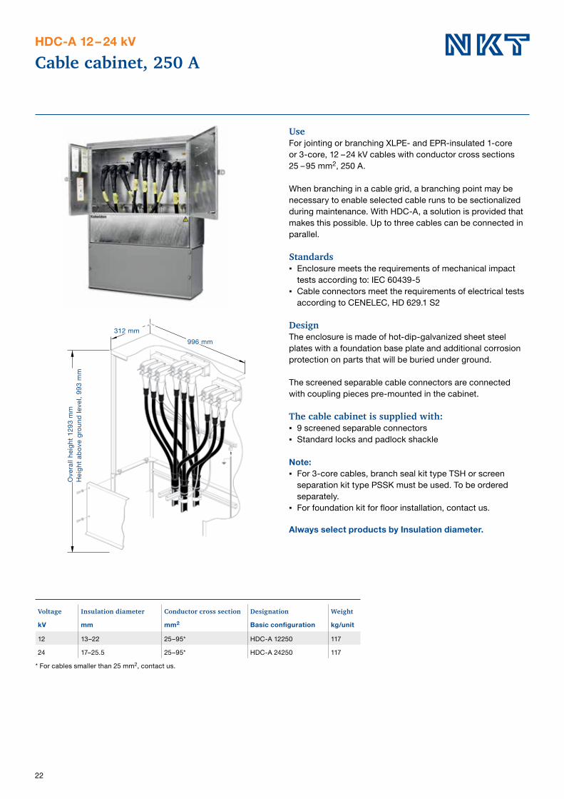
Cable cabinet, 250 AHDC-A 12 – 24 kV
UseFor jointing or branching XLPE- and EPR-insulated 1-core or 3-core, 12 – 24 kV cables with conductor cross sections 25 – 95 mm2, 250 A.
When branching in a cable grid, a branching point may be necessary to enable selected cable runs to be sectionalized during maintenance. With HDC-A, a solution is provided that makes this possible. Up to three cables can be connected in parallel.
Standards Enclosure meets the requirements of mechanical impact
tests according to: IEC 60439-5 Cable connectors meet the requirements of electrical tests
according to CENELEC, HD 629.1 S2
DesignThe enclosure is made of hot-dip-galvanized sheet steel plates with a foundation base plate and additional corrosion protection on parts that will be buried under ground.
The screened separable cable connectors are connectedwith coupling pieces pre-mounted in the cabinet.
The cable cabinet is supplied with: 9 screened separable connectors Standard locks and padlock shackle
Note: For 3-core cables, branch seal kit type TSH or screen
separation kit type PSSK must be used. To be ordered separately.
For foundation kit for floor installation, contact us.
Always select products by Insulation diameter.
Voltage Insulation diameter Conductor cross section Designation Weight
kV mm mm2 Basic configuration kg/unit
12 13–22 25–95* HDC-A 12250 117
24 17–25.5 25–95* HDC-A 24250 117
* For cables smaller than 25 mm2, contact us.
Ove
rall
heig
ht 1
293
mm
Hei
ght a
bove
gro
und
leve
l, 99
3 m
m
312 mm996 mm

23
Designation Description Qty Weight See page
kit kg/unit
IP 250 Screened insulating plug 1 0.8 23
IH-A 24250 Insulating hood 3 2.3 23
MA 250 Measurement adapter 1 0.3 23
KA 250 Busbar 1 0.5 23
PSSL 1 L Screen separation kit, heat-shrink, reinforced and extended,for 3-core cable 10 – 70 mm2 / 12 kV, 10 – 35 mm2 / 24 kV 1 3.3 54
PSSL 2 L Screen separation kit, heat-shrink, reinforced and extended,for 3-core cable, 95 – 300 mm2 / 12 kV, 50 – 300 mm2 / 24 kV 1 3.9 54
TSH Branch seal 1 0.3–1.0 55
UKRA 90 Clamp for fixing cables 1 0.23 68
Accessories, to be ordered separatelyCable cabinet, HDC 12 – 24 kV, 250 A
Ø 13
35
IP 250Screened insulating plug for installation in the connector so that the cable can be energized even when the cable connector is disconnected.
KA 250Transversal anchor bar.
UKRA 90Universal clamp.
IH-A 24250Insulating hood made of flexiblerubber with outer conductive layer and an already installed insulating rod. To be mounted on the bushing in HDC-A 250 for insulation when a cable is temporary disconnected and remaining cables are under voltage.
PSSK LHeat-shrink screen separation kitfor cables with Al/Cu-wire screen.
MA 250Measurement adapter used for mega ohm Ω measurements and to perform different measurements up to 5 kV DC, for example deter- mination of phases.
TSHBranch seal kit

24
Cable cabinet, 630 AHDC-A 12 – 36 kV
UseFor jointing or branching of XLPE- and EPR-insulated, 12 – 36 kV 1-core or 3-core cables with conductor cross sections 25 – 630 mm2, 630 A. Up to four cables can be connected in parallel.
When branching in a cable grid, a branching point may be necessary to enable selected cable runs to be sectionalized during maintenance. With HDC-A a solution is provided that makes this possible.
Standards The cable cabinet meets the requirements for mechanical
impact testing according to IEC 60439-5. The cable connectors meet the electrical requirements
according to CENELEC, HD 629.1 S2.
DesignThe enclosure is made of hot-dip-galvanized sheet steel plates with a foundation base plate and additional corrosion protection on parts that will be buried under ground.
The screened separable cable connectors are connected with coupling pieces pre-mounted in the cabinet.
The cable cabinet is supplied with: 6 screened separable connectors Locks and padlock shackle
Required when connecting more cables: 6 screened separable cable connectors type CSE-A. Parallel coupling piece type PC.
Note: For 3-core cables, branch seal kit type TSH or screen
separation kit type PSSK must be used. To be ordered separately.
For foundation kit for floor installation, contact us.
Always select products by Insulation diameter.
Ove
rall
heig
ht 1
293
mm
Hei
ght a
bove
gro
und
leve
l, 99
3 m
m
522 mm996 mm
The third cable connector is to be ordered separately.
Voltage Insulation diameter Conductor cross section Designation Weight
kV mm mm2 Basic configuration kg/unit
12 13–20 25–70 HDC-A 12630-01 140
12 18.5–30.5 95–300 HDC-A 12630-02 140
12 30.5–45 400–630 HDC-A 12630-03 140
24 17–24 25–70 HDC-A 24630-01 140
24 22.5–35 95–300 HDC-A 24630-02 140
24 30.5–45 400–630 HDC-A 24630-03 140
36 24.5–34 50–95 HDC-A 36630-01 140
36 27.5–42 95–300 HDC-A 36630-02 140
36 38–55 400–630 HDC-A 36630-03 140

25
Designation Description Qty. Weight See page
per kit kg/kit
CSE-A Screened separable connector. 3 Olika 31–33
KA 630 Transversal anchor bar, add two when using 1-core cables 1 0.8 25
IH-A 24630 Insulating sealing hood, 12 – 24 kV 3 5.2 25
IH-A 42630 Insulating sealing hood, 36 kV 3 5.2 25
PC 630-3 Parallel coupling piece, 630, 12 – 24 kV 3 1.1 25
PC 630-3 L Parallel coupling piece, 630, 36 kV 3 1.1 25
PG 630 Bushing for voltage testing of the cable, 12 – 24 kV 1 1.5 25
PG-A 630 Bushing for voltage testing of the cable, 36 kV 1 2.0 25
IP 630 Insulating plug, 630 A 1 0.8 25
MA-A 630 Measurement adapter, 630 A 3 0.1 25
PC 630/250 Parallel coupling piece between CSE-A 630 and CSE-A 250 3 3.0 25
PSSK 2 L Screen separation for 3-core cable 50 – 95 mm² 1 2.5 / 3.9 / 2.5 54
PSSK 3 L Screen separation for 3-core cable 95 – 300 mm² 1 3.4 / 4.8 / 3.4 54
TSH Branch seal 1 0.3–1.0 55
UKRA 90 Clamp for fixing cables 1 0.23 68
Accessories, to be ordered separatelyCable cabinet, HDC-A 12 – 36 kV, 630 A
CSE-AScreened separable connector 630 A for connection of an external cable.
PC 630-3Parallel coupling piece. Replaces the plug in CSE-A when making a parallel connection to another CSE-A 12 – 24 kV.
PC 630-3 LParallel coupling piece. Replaces the plug in CSE-A when making a parallel connection to another CSE-A 36 kV.
PC 630/250Connector for connecting a CSE-A 250, in parallel with a previously mounted CSE-A 630. 3 pieces in the kit, tool is included.
MA-A 630Measurement adapter used for mega ohm Ω measure- ments and to perform different measurements up to 5 kV DC, for determination of phases.
IH-A 24630, IH-A 42630Insulating sealing hood of flexiblerubber with outer conductive layerand an already installed insulatinghood. To be installed in HDC-A 630 instead of cable connector in order to temporarily insulate 630 A switchgear or transformer bushings.
Ø 13
35 KA 630Transversal anchor bar.
PG 630Bushing for voltage testing of the cable. Adapted to cable connectors 12 – 24 kV.
IP 630Screened insulating plug forinstallation in the screened sepa-rable connector so that the cable can be energized even when the connector is disconnected from the switchgear or transformer.
UKRA 90Universal clamp.
TSHBranch seal kit.
PG-A 630Bushing for voltage testing of the cable. Adapted to cable connectors 36 kV.
PSSK LScreen separation kit for 3-corecables with Al/Cu-wire screenincluding heat-shrink branch seal and 2 meters long protective hoses.

26
Premolded screened separable cable connectors
CSE-A 12 – 24 kV, 250 A, CSS-A 12 – 24 kV, 250 A
Application areasPremolded screened separable connectors for XLPEandEPR-insulated 1- or 3-core cables with Al- or Cuconductorsfor 12 – 24 kV. Can be installed both indoors and outdoors.
Fits standard bushings of outer cone type according toEN 50181. Connector with rated current: 250 A: Interface A with plug-in Ø 7.9 mm.
StandardMeets the requirements of: CENELEC, HD 629.1 S2
DesignCSE-A and CSS-A are manufactured in rubber with threelayers; a conductive inner layer, an insulation layer and aconductive outer layer, that are vulcanized together for thebest possible interface between the layers.
The cable connectors include both a capacitive test pointwith protection and an integrated earthing wire.
Delivered in 3-phase kits, complete with cable lugs, bolt connection and stress grading adapter, designed to ensure a reliable installation.
Note: For 3-core cable with common copper screen wires, a
screen separation kit or a branch seal kit must be used. To be ordered separately.
Always select products by Insulation diameter.
Voltage Insulation diameter
Conductor cross section
Designation Weight
kV mm mm2 kg/unit
Elbow cable connector
12 10–12 10–16 CSE-A 12250-01 2.2
12 13–22 25–95 CSE-A 12250-02 2.2
24 13–22 10–16 CSE-A 24250-01 2.2
24 17–25.5 25–95 CSE-A 24250-02 2.2
Straight cable connector
12 10–12 10–16 CSS-A 12250-01 2.2
12 13–22 25–95 CSS-A 12250-02 2.2
24 13–22 10–16 CSS-A 24250 01 2.2
24 17–25.5 25–95 CSS-A 24250 02 2.2
Elbow cable connector complete with screen separation kit
12 10–12 10–16 CSE-A 12250-01 P 5.5
12 13–22 25–95 CSE-A 12250-02 P 5.5
24 13–22 10–16 CSE-A 24250-01 P 5.5
24 17–25,5 50–95 CSE-A 24250-02 P 6.1
CSE-A 12250CSE-A 24250
CSS-A 12250CSS-A 24250
Standard bushing EN 50181 Interface A, 250 A Contact type: Plug-in approx. Ø 7.9 mm
R3R1C 2 x 45°
Bail holder
Ø 4
3.5
Ø 4
8.5
Ø 9
0
Ø 3
1
1
Ø 3
2.5
9 48
CSE-A 250 A, 12 – 24 kV
Ø 63C-C
70 min 124
211
Ø 58
29
CSS-A 250 A, 12 – 24 kV
C-C 80 min
263
Ø 65
66
Dimensions in mm.

27
Premolded screened separable connectorfor cables with Cu-tape screen
CSE-A 12 – 24 kV, 250 A
Application areasPremolded screened separable connectors for XLPE- andEPR-insulated 1- or 3-core 12 – 24 kV cables with Al- orCu-conductors with copper tape screens, with or withoutaluminium or steel wire armouring. Can be installed bothindoors and outdoors.
Fits standard bushings of outer cone type according toEN 50181. Connector with rated current: 250 A: Interface A with plug-in Ø 7.9 mm.
StandardMeets the requirements of: CENELEC, HD 629.1 S2
DesignCSE-A is manufactured in rubber with three layers; a conductive inner layer, an insulation layer and a conductiveouter layer, that are vulcanized together for the best possible interface between the layers. The cable connectors include both a capacitive test point with protection and an integrated earthing wire.
Delivered in 3-phase kits, complete with cable lugs, boltconnection, earthing kit and stress grading adapters. The adapters are designed to ensure a reliable installation.
For 3-core cables, a branch seal kit is included.
Always select products by Insulation diameter.
Voltage Insulation diameter
Conductor cross section
Designation Outer sheathdiameter
Weight
kV mm mm2 mm kg/unit
Elbow cable connector, 3 x 1-core
12 13–22 25–95 CSE-A 12250-02 R – 2.7
24 19–25.5 35–95 CSE-A 24250-02 S – 2.7
Elbow cable connector, 3-core
12 13–22 25–50 CSE-A 12250-02 RA 31–50 2.9
12 13–22 70–95 CSE-A 12250-02 RB 44–70 2.9
24 19–25.5 35–95 CSE-A 24250-02 SB 47–70 2.9
Dimensions in mm.
CSE-A 12250CSE-A 24250
Standard bushing EN 50181 Interface A, 250 A Contact type: Plug-in approx. Ø 7,9 mm
R3R1
C 2 x 45°
Bail holder
Ø 4
3.5
Ø 4
8.5
Ø 9
0
Ø 3
1
1
Ø 3
2.5
9 48
CSE-A 250 A, 12 – 24 kV
Ø 63C-C
70 min 124
211
Ø 58
29

28
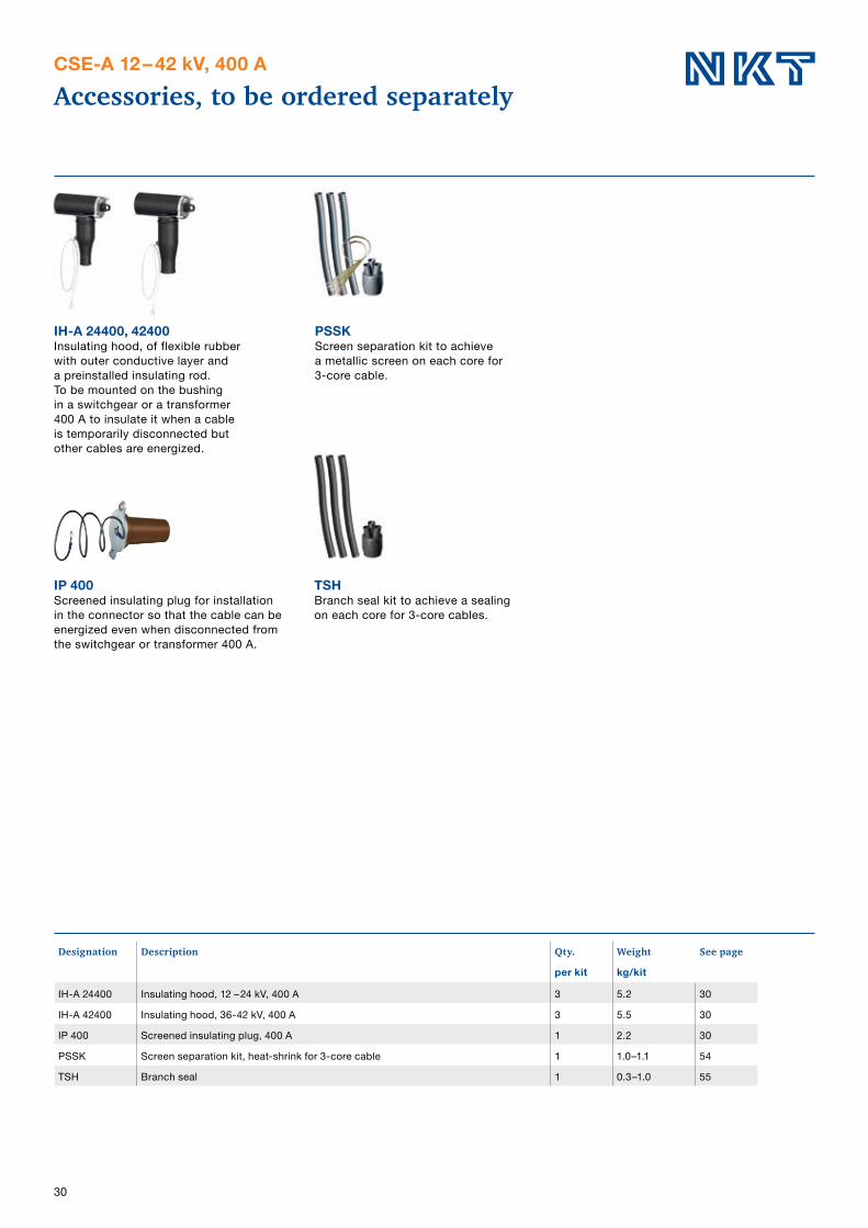
Designation Description Qty. Weight See page
per kit kg/kit
IH-A 24250 Insulating hood, 12 – 24 kV, 250 A 3 2.3 28
IP 250 Screened insulating plug, 250 A 1 0,8 28
PSSK Screen separation kit, heat-shrink for 3-core cable 1 1.0–1.1 54
TSH Branch seal kit 1 0.3–1.0 55
PC 630/250 Parallel coupling piece 3 3.0 28
JP 250 Earthing device, 250 A 1 2.7 28
CU 250 Coupling piece between two cable connectors, 250 A 1 0.2 28
MA 250 Measurement adapter, 250 A 1 0.3 28
Accessories, to be ordered separatelyCSE-A and CSS-A 12 – 24 kV, 250 A
MA 250Measurement adapter used for mega ohm Ω measurements and to perform different measurements up to 5 kV DC, for example determination of phases, 250 A.
IH-A 24250Insulating hood of flexible rubber with outer conductive layer and a preinstalled insulating rod. To be mounted on the bushing in a switchgear or a transformer 250 A to insulate it when a cable is temporarily disconnected but other cables are energized.
IP 250Screened insulating plug for installation in the connector so that the cable can be energized even when disconnected from the switchgear or transformer 250 A.
CU 250Coupling piece to connect two connectors.
JP 250Earth circuit connector for short-circuit protective earthing. For mounting on the disconnected connector CSE-A for 250 A.
PSSKScreen separation kit to achieve a metallic screen on each core for 3-core cables.
PC 630/250Parallel coupling piece. Replaces the plug in CSE-A 630 A when making a parallel connection to CSE-A 250 A. Delivered in 3-phase kits and hex bit socket.
TSHBranch seal kit to achieve a sealing on each core for 3-core cables.

29
Premolded screened separable cable connector
CSE-A 12 – 42 kV, 400 A
Application areasPremolded screened separable connectors for XLPE- andEPR-insulated 1- or 3-core 12 – 24 kV cables with Al- orCu-conductors with copper tape screens, with or withoutaluminium or steel wire armouring. Can be installed bothindoors and outdoors.
Fits standard bushings of outer cone type according toEN 50181. Connector with rated current: 400 A: series 400 interface type B with plug-in Ø 14 mm.
StandardMeets the requirements of: CENELEC, HD 629.1 S2
DesignCSE-A is manufactured in rubber with three layers; a conductive inner layer, an insulation layer and a conductiveouter layer, that are vulcanized together for the best possible interface between the layers.
The cable connectors include both a capacitive test point with protection and an integrated earthing wire.
Delivered in 3-phase kits, complete with cable lugs, bolt connection, earthing kit and stress grading adapters. The adapters are designed to ensure a reliable installation.
Note: For 3-core cables, a branch seal kit is included.
Always select products by Insulation diameter.
Voltage Insulation diameter
Conductor cross section
Designation Ratedcurrent
Weight
kV mm mm2 A kg/unit
12 13–20 25–70 CSE-A 12400-01 400 6.1
12 18.5–30.5 95–300 CSE-A 12400-02 400 6.6
24 17–24 25–70 CSE-A 24400-01 400 6.1
24 22.5–35 95–300 CSE-A 24400-02 400 6.6
36 24.5–34 50-95 CSE-A 36400-01 400 6.1
36 27.5–42 95-300 CSE-A 36400-02 400 6.6
42 24.5–34 50–70 CSE-A 42400-01 400 6.1
42 27.5–42 95–300 CSE-A 42400-02 400 6.6
Dimensions in mm.
CSE-A 12400
Standard bushing EN 50181 Interface B, 400 A Contact type: Plug-in Ø14
R3
Ø 4
6
Ø 7
0Ø
102
115.5Bail holder
40R3R3
Ø 5
6
90
CSE-A 400 A, 12 – 24 kV
Ø 80C-C
85 min 173
256
Ø 72
34
CSE-A 400 A, 36 – 42 kV
Ø 80C-C
85 min 195
284
Ø 74
34
CSE-A 24400
30
Designation Description Qty. Weight See page
per kit kg/kit
IH-A 24400 Insulating hood, 12 – 24 kV, 400 A 3 5.2 30
IH-A 42400 Insulating hood, 36-42 kV, 400 A 3 5.5 30
IP 400 Screened insulating plug, 400 A 1 2.2 30
PSSK Screen separation kit, heat-shrink for 3-core cable 1 1.0–1.1 54
TSH Branch seal 1 0.3–1.0 55
Accessories, to be ordered separatelyCSE-A 12 – 42 kV, 400 A
IH-A 24400, 42400Insulating hood, of flexible rubber with outer conductive layer and a preinstalled insulating rod.To be mounted on the bushing in a switchgear or a transformer 400 A to insulate it when a cable is temporarily disconnected but other cables are energized.
IP 400Screened insulating plug for installation in the connector so that the cable can be energized even when disconnected from the switchgear or transformer 400 A.
PSSKScreen separation kit to achieve a metallic screen on each core for 3-core cable.
TSHBranch seal kit to achieve a sealing on each core for 3-core cables.

31
Premolded screened separable cable connector
CSE-A 12 – 42 kV, 630 A
Application areasPremolded screened separable connector for XLPE- andEPR-insulated 1- or 3-core cables with Al- or Cu-conductors for 12 – 42 kV. Can be installed both indoors and outdoors.Fits standard bushings of outer cone type according to EN 50181. Connector with rated current: 630 A: Interface C1 with bolt M16. 1250 A: Interface C2 with bolt M16.
StandardMeets the requirements of: CENELEC, HD 629.1 S2
DesignCSE-A is manufactured in rubber with three layers;a conductive inner layer, an insulation layer and a conductive outer layer, that are vulcanized together for the best possible interface between the layers.The cable connector includes both a capacitive test point with protection and an integrated earthing wire. Delivered in 3-phase kits, complete with cable lugs, bolt
connection and stress grading adapter, designed to ensure a reliable installation.
Note: For 3-core cables with common Cu-screen wires,
a screen separation kit or a branch seal kit must be used. To be ordered separately.
Always select products by Insulation diameter.
Voltage Insulation diameter
Conductor cross section
Designation Weight
kV mm mm2 kg/unit
12 13–20 25–70 CSE-A 12630-01 5.1
12 18.5–30.5 95–300 CSE-A 12630-02 5.5
12 30.5–45 400–630 CSE-A 12630-03 7.7
24 17–24 25–70 CSE-A 24630-01 5.1
24 22.5–35 95–300 CSE-A 24630-02 5.5
24 30.5–45 400–630 CSE-A 24630-03 7.7
36 24.5–34 50-95 CSE-A 36630-01 6.1
36 27.5–42 95-300 CSE-A 36630-02 6.6
36 38.0–55 400-630 CSE-A 36630-03 8.7
42 24.5–34 50–70 CSE-A 42630-01 6.1
42 27.5–42 95–300 CSE-A 42630-02 6.6
42 38–55 400–630 CSE-A 42630-03 8.7
Cable connector complete with screen separation kit
12 13–20 25–70 CSE-A 12630-01 P 8.4
12 18.5–30.5 95–300 CSE-A 12630-02 P 9.4
24 17-24 50–70 CSE-A 24630-01 P 9
24 22.5–35 95–300 CSE-A 24630-02 P 9.4
36 23–34 50–95 CSE-A 36630-01 P 10
36 27.5–42 95–300 CSE-A 36630-02 P 1.4
Dimensions in mm.
CSE-A 12630, CSE-A 24630 CSE-A 36630, CSE-A 42630
CSE-A 630 A, 36 – 42 kV sizes 1 – 2.
Ø 81C-C
85 min 194
283
Ø 74
9
CSE-A 630 A, 12 – 24 kV, size 3
Ø 85C-C
90 min 180
314
90
9
CSE-A 630 A, 12 – 24 kV, sizes 1 – 2
Ø 81C-C
85 min 172
256
Ø 72
9
CSE-A 630 A, 36 – 42 kV size 3.
9Ø 85C-C
90 min 202
314
90
Ø 4
6Ø
56
R3R3
Ø 7
0
11 90
R3 1.529
Standard bushing EN 50181 Interface: C1, 630 AInterface: C2, 1250 A Contact type: Bolt M16

32
Premolded screened separable cable connectorfor cables with copper tape screen
CSE-A 12 – 36 kV, 630 A
Application areasPremolded screened separable connector for XLPE- and EPR-insulated 1- or 3-core 12 – 36 kV cables, with Al- or Cu-conductors with Cu-tape screens, with or without aluminium or steel wire armouring. Can be installed both indoors and outdoors.Fits standard bushings of outer cone type according toEN 50181. Connectors with rated current: 630 A: Interface type C1 with bolt M16. 1250 A: Interface type C2 with bolt M16.
StandardMeets the requirements of: CENELEC, HD 629.1 S2
DesignCSE-A is manufactured in rubber with three layers; a con- ductive inner layer, an insulation layer and a conductive outer layer, that are vulcanized together for the best possible inter-face between the layers. The cable connector includes both a capacitive test point with protection and an integrated earthing wire. Delivered in 3-phase kits, complete with cable lugs,
bolt connection, earthing kit and stress grading adapters. The adapters are designed to ensure a reliable installation. For 3-core cables, a branch seal kit is included.
Always select products by Insulation diameter.
Voltage Insulation diameter
Conductor cross section
Outer sheathdiameter
Designation Weight
kV mm mm2 mm kg/unit
Elbow cble connectors, 3 x 1-core cables
12 13–20 25–70 – CSE-A 12630-01 R 5.6
12 19–29 95–300 – CSE-A 12630-02 S 6.0
12 30.5–37 400 – CSE-A 12630-03 T 8.2
24 19–24 35–70 – CSE-A 24630-01 S 5.6
24 25–35 95–300 – CSE-A 24630-02 T 6.0
24 30.5–37 400 – CSE-A 24630-03 T 8.2
36 19–29 50–70 – CSE-A 36630-01 S 6.8
36 27.5–37 95–300 – CSE-A 36630-02 T 7.3
36 38–50 400 – CSE-A 36630-03 U 9.4
Elbow cable connectors, 3-core cables
12 13–20 25–70 31–50 CSE-A 12630-01 RA 5.8
12 19–29 95–185 47–70 CSE-A 12630-02 SB 6.2
12 25–30.5 240–300 58–94 CSE-A 12630-02 TB 6.2
12 30.5–37 400 58–94 CSE-A 12630-03 TB 8.4
24 19–24 35–70 47–70 CSE-A 24630-01 SB 5.8
24 25–35 95–300 58–94 CSE-A 24630-02 TB 6.2
24 30.5–37 400 65–110 CSE-A 24630-03 TB 8.4
36 19–29 50–95 58–94 CSE-A 36630-01 SB 6.8
36 27.5–37 95–300 65–110 CSE-A 36630-02 TB 7.3
Dimensions in mm.
CSE-A 12630, CSE-A 24630 CSE-A 36630
CSE-A 630 A, 36 – 42 kV sizes 1 – 2.
Ø 81C-C
85 min 194
283
Ø 74
9
CSE-A 630 A, 12 – 24 kV, size 3
Ø 85C-C
90 min 180
314
90
9
CSE-A 630 A, 12 – 24 kV, sizes 1 – 2
Ø 81C-C
85 min 172
256
Ø 72
9
CSE-A 630 A, 36 – 42 kV size 3.
9Ø 85C-C
90 min 202
314
90

33
Designation Description Qty. Weight See page
per kit kg/kit
IH-A 24630 Insulating hood, 12 – 24 kV, 630 A 3 5.2 33
IH-A 42630 Insulating hood, 36-42 kV, 630 A 3 5.5 33
IP 630 Screened insulating plug, 630 A 1 2.2 33
PC 630 / 250 Parallel coupling piece 3 3.0 33
PSSK Screen separation kit, heat-shrink for 3-core cable 1 1.0–1.1 54
TSH Branch seal 1 0.3–1.0 55
MA-A 630 Measurement adapter, 630 A 3 0.2 33
CSAP-A Surge arrestor, 630 A, 12 – 24 kV 1 3.6–5.0 35
PG 630 Bushing for voltage testing, 630 A, 12 – 24 kV 1 1.5 33
PG-A 630 Bushing for voltage testing, 630 A, 36 – 42 kV 1 2.0 33
CSEP-A Parallel cable connector 1 5.7–9.8 34
JPB 630 Earthing device, 630 A 1 5.0 33
JPA V Tool for earthing-for-work device, JPB 630 1 1.8 33
Accessories, to be ordered separatelyCSE-A 12 – 42 kV, 630 A
IH-A 24630, IH 42630Insulating hood, of flexible rubber with outer conductive layer and a preinstalled insulating rod. To be mounted on the bushing in a switchgear or a transformer 630 A to insulate it when a cable is temporarily disconnected but other cables are energized.
MA-A 630Measurement adapter used for mega ohm Ω measurements and to perform different measure- ments up to 5 kV DC, for example determination of phases, 630 A.
PC 630/250Parallel coupling piece. Replaces the plug in CSE-A 630 A when making a parallel connection to CSE-A 250 A. Delivered in 3-phase kits and hex bit socket.
PG 630Bushing for voltage testing.
IP 630Screened insulating plug for installation in the connector so that the cable can be energized even when disconnected from the switchgear or transformer 630 A.
PG-A 630Bushing for voltage testing, 36 – 42 kV.
JPB 630Universal earthing device with two fields of application for 630 A and 12-42 kV: As earthing-for-work device
mounted at the back of a connected cable connector CSE-A for 630 A.
As short-circuit protective earthing mounted in front of a disconnected cable connector CSE-A for 630 A.
JPA VTool for earthing device, JPB 630.
CSAP-ASurge arrestor, 630 A.
CSEP-AParallel cable connector.
PSSKScreen separation kit to achieve a metallic screen on each core for 3-core cable.
TSHBranch seal kit to achieve a sealing on each core for 3-core cable.

34
Parallel separable connector for 630 A cable connector
CSEP-A 12 – 42 kV
Application areaCSEP-A is a screened separable parallel cable connectordesigned to be connected to a screened separable cableconnector type CSE-A 630. Used with XLPE- och EPR- insulated 1- or 3-core cables with Al- or Cu-conductor for 12 – 42 kV.
Standard Fulfills the requirements of CENELEC HD 629.1 S2.
DesignCSEP-A is manufactured in rubber with three layers; a conductive inner layer, an insulation layer and a conductiveouter layer that are vulcanized together for the best possibleinterface between the layers.
When installing CSEP-A on the CSE-A the plug and the pro-tective cap must be moved from CSE-A to parallel connector CSEP-A. In that way the capacitive test point is re-established.
Delivered in 3-phase kits complete with cable lugs, bolt connections, stress grading adapters and also an integrated earthing wire.
Note: For 3-core cables with common Cu-screen wires, a screen
separation kit or a branch seal kit must be used. For screen separation kit see table at page 54.
Always select products by Insulation diameter.
Voltage Conductor cross section
Insulation diameter
Designation Weight
kV mm2 mm kg/kit
12 25–70 13–20 CSEP-A 12630-01 5.7
12 95–300 18.5–30.5 CSEP-A 12630-02 6.1
12 400–630 30.5–45 CSEP-A 12630-03 8.6
24 25–70 17–24 CSEP-A 24630-01 5.7
24 95–300 22.5–35 CSEP-A 24630-02 6.1
24 400–630 30.5–45 CSEP-A 24630-03 8.6
36 50–95 24.5–34 CSEP-A 36630-01 6.7
36 95–300 27.5–42 CSEP-A 36630-02 7.1
36 400–630 38–55 CSEP-A 36630-03 9.8
42 50–70 24.5–34 CSEP-A 42630-01 6.7
42 95–300 27.5–42 CSEP-A 42630-02 7.1
42 400–630 38–55 CSEP-A 42630-03 9.8
Parallel connector complete with screen separation kit
12 13–20 25–70 CSEP-A 12630-01P 9
12 18.5–30.5 95–300 CSEP-A 12630-02P 10
24 17–24 50–70 CSEP-A 24630-01P 9.6
24 22.5–35 95–300 CSEP-A 24630-02P 10
36 23–34 50–95 CSEP-A 36630-01P 10.6
36 27.5–42 95–300 CSEP-A 36630-02P 11.9
Dimensions in mm.
CSEP-A, 12 – 24 kV sizes 1 – 2
256
72
85 min 85100 9
CSEP-A, 12 – 24 kV size 3
314
90
85 min 90114 9
283
74
81 min 85122 9
CSEP-A, 36 – 42 kV sizes 1 – 2
314
90
85 min 90136 9
CSEP-A, 36 – 42 kV size 3

35
Parallel screened separable connectorfor cable with copper tape screen, 630 A
CSEP-A 12 – 42 kV
Application areaCSEP-A is a screened separable parallel connector designedto be connected to a screened separable connector typeCSE-A 630. Used with XLPE- and EPR-insulated 1- or 3-core12 – 36 kV cables, with Al- or Cu-conductors with copper tapescreens, with or without aluminium or steel wire armouring.
Standard Fulfills the requirements of CENELEC HD 629.1 S2.
DesignCSEP-A is manufactured in rubber with three layers; a conductive inner layer, an insulation layer and a conductive outer layer that are vulcanized together for the best possible interface between the layers.When installing CSEP-A on the CSE-A, the plug and the protective cap must be moved from CSE-A to the parallel connector CSEP-A. In that way the capacitive test point is re-established. Delivered in 3-phase kits complete with cable lugs,
bolt connections, stress grading adapters and also an integrated earthing wire.
Note: For 3-core cables with common Cu-tape screen,
a screen separation kit or a branch seal kit must be used. See table at page 54.
Always select products by Insulation diameter.
Voltage Insulation diameter
Conductor cross section
Designation Weight
kV mm mm2 kg/kit
Parallel connector for 3 x 1-core cables
12 13–20 25–70 CSEP-A 12630-01 R 5.8
12 18.5–30.5 95–300 CSEP-A 12630-02 S 6.2
12 30.5–45 400 CSEP-A 12630-03 T 8.7
24 17–24 35–70 CSEP-A 24630-01 S 5.8
24 22.5–35 95–300 CSEP-A 24630-02 T 6.2
24 30.5–45 400 CSEP-A 24630-03 T 8.7
36 24.5–34 50–70 CSEP-A 36630-01 S 6.8
36 27.5–42 95–300 CSEP-A 36630-02 T 7.2
36 38–55 400 CSEP-A 36630-03 U 9.9
Parallel connector for 3-core cables
12 13–20 25–70 CSEP-A 12630-01 RA 5.8
12 18.5–30.5 95–185 CSEP-A 12630-02 SB 6.2
12 18.5–30.5 240–300 CSEP-A 12630-02 TB 6.2
12 30.5–45 400 CSEP-A 12630-03 TB 8.7
24 17–24 35–70 CSEP-A 24630-01 SB 5.8
24 22.5–35 95–300 CSEP-A 24630-02 TB 6.2
24 30.5–45 400 CSEP-A 24630-03 TB 8.7
36 24.5–34 50–95 CSEP-A 36630-01 SB 6.8
36 27.5–42 95–300 CSEP-A 36630-02 TB 7.2
Dimensions in mm.
CSEP-A, 12 – 24 kV sizes 1 – 2
256
72
81 min 85100 9
CSEP-A, 12 – 24 kV size 3
314
90
85 min 90114 9
283
74
81 min 85122 9
CSEP-A, 36 – 42 kV sizes 1 – 2
314
90
85 min 90136 9
CSEP-A, 36 – 42 kV size 3

36
Dimensional drawings
Parallel connection of CSE-A and CSEP-A 12 – 42 kVParallel connection of two CSE-A 12 – 42 kV
Connection of parallel connector type CSEP-A to cable connector typeCSE-A meets the requirements according to the standard CENELEC HD 629.1 S2. Dimensions in mm.
CSEP-A size 1 – 2 + CSE-A size 1 – 2 CSEP-A size 3 + CSE-A size 1 – 2 CSEP-A size 1 – 2 + CSE-A size 3 CSEP-A size 3 + CSE-A size 3
CSEP-A size 3 + CSE-A size 1 – 2CSEP-A size 1 – 2 + CSE-A size 1 – 2 CSEP-A size 1 – 2 + CSE-A size 3 CSEP-A size 3 + CSE-A size 3
Parallel connection of two cable connectors type CSE-A with parallel coupling piece PC 630-3 / PC 630-3 Lmeets the requirements according to the standard CENELEC HD 629.1 S2.
Parallel connection of two CSE-A size 1 – 2, 12 – 24 kV
353 369
Parallel connection of two CSE-A size 3, 12 – 24 kV
397
Parallel connection of two CSE-A size 1 – 2, 36 kV
413
Parallel connection of two CSE-A size 3, 36 kV
36 –
4 2
kV12
– 2
4 kV
278
97
289
105
286
101 109
298
339
128
324
117
330
124
316
113
202194180
172
PSSK TSH SSH
Accessories, to be ordered separately
Designation Description See page
TSH, SSH Branch seal and additional hoses 55
PSSK Screen separation kit 54

37
Surge arresters for 630 A separable connector
CSAP-A 6 – 24 kV
Application areaCSAP-A is a screened separable surge arrester designedto be connected in parallel with screened separable cable connector type CSE-A 630 A. Protects electrical components against overvoltage
and transients.
Standard Fulfills the requirements of IEC 60099-4. Parallel connection of surge arrester CSAP-A connected
to cable connector CSE-A meets the requirements accord-ing to standard CENELEC HD 629.1 S2.
DesignCSAP-A includes a premolded body, manufactured in threelayers; a conductive inner layer, an insulation layer and a conductive outer layer vulcanized together for the bestpossible interface between the layers. The surge arrester’s active part is made of metal oxide. The connected earth braid manages short circuit currents according to the standard. When installing CSAP-A on the CSE-A 630, the plug and the protective cap must be moved from CSE-A to the surge arrester CSAP-A. In that way the capacitive test point is re-established. Delivered in 1-core kits complete with bolt connection, earth braid and also an integrated earthing wire.Always select products by Insulation diameter.
Voltage Designation WeightkV kg/kit
6 CSAP-A 6/5 kA 2.6
6 CSAP-A 6/10 kA 3.0
12 CSAP-A 12 5 kA 3.6
12 CSAP-A 12 10 kA 4.0
24 CSAP-A 24 5 kA 4.6
24 CSAP-A 24 10 kA 5.0
Uc continuous operating voltage rms
Ur rated voltage rms
Ures residual voltage peak at 8/20 µs
In nominal discharge current 8/20 µs
Ihc high current impulse 4/10 µs
Is short circuit rating 50 Hz rms for 0.2 s
Dimensions in mm.
CSE-A sizes 1 – 2 + CSAP-A CSE-A size 3 + CSAP-A
295 303
114
90
9 mm 89.5 min 90
266
114
90
9 mm 89.5 min 90
360
CSAP-A sizes 24 / 5 and 24 / 10
CSAP-A sizes 12 / 5 and 12 / 10
Technical data
Explanation of symbols according to IEC 60099-4
Designation Uc Ur Ures In Ihc Is IEC line discharge classkV kV kV kA kA kA
CSAP-A 6/5 kA 6 5 16 –
CSAP-A 6/10 kA 6 10 16 1
CSAP-A 12 5 kA 12 15 39.1 5 65 16 –
CSAP-A 12 10 kA 12 15 40 10 100 16 1
CSAP-A 24 5 kA 24 30 78.2 5 65 16 –
CSAP-A 24 10 kA 24 30 80 10 100 16 1

38
Shrouded termination, 630 ATB-A 12, 12 kV
UseShrouded cable termination for connecting XLPE and EPR- insulated 12 kV cables in switchgear, type NKT SafeLink.
StandardMeets the requirements of: CENELEC, HD 629.1
DesignTB-A is a shrouded cable termination made of rubber. Supplied in complete 3-phase kits including cable terminations, two-piece boots, cable lugs with shear-off bolts, grease, cleaning cloth and installation instructions. Due to the smart installation method the upper part of the two-piece boot will stick to the bushing.
For measuring, the lower part of the boot can easily bepulled down to expose the palm of the bushing.
Note: For 3-core cables with common Cu-screen wires,
a screen separation kit or a branch seal kit must be used.
Connector cross section Designation Length Weight
mm2 mm kg/kit
Three 1-core or one 3-phase kits
10–35 TB-A 12630-1 400 2.65
50–150 TB-A 12630-2 400 2.90
185–300 TB-A 12630-3 450 3.10
Accessories, to be ordered separately
Designation Description See page
PSSK Screen separation kit 54
TSH Branch seal 55
PSSK TSH

39
Shrouded termination, 630 AKAP 630, 12 – 24 kV
UseFor XLPE- and EPR-insulated 1- or 3-core cables with Al orCu conductor for 12 – 24 kV.
KAP can be used to connect a cable to gas-insulatedswitchgear and in other compact installations, as well as for substation transformers. To be used indoors only.
StandardsMeets the requirements of: SEN 24 14 34 SS 424 14 17 Edition 4
DesignKAP is an insulated connector made of rubber. It is suppliedcomplete with cable termination and bolt cable lug. Thecovers are provided with a removable plastic plug to allowdirect voltage testing on the conductor.
Also available for parallel installation. The connectors aresupplied in 3-phase kits.
Note: For 3-core cables with common Cu-screen wires,
a screen separation kit or a branch seal kit must be used. For plug-in connector 250 A or 400 A, choose CSE-A.
~316
130
C-C 133
KAP 630 P SCLInstalled in parallel with KAP 630 SCL.
70KAP 630 SCL
86
260
185
Dimensions in mm.
Always select products by Insulation diameter.
Type Insulation diameter Conductor cross section Designation Connection type WeightØ 12 kV 24 kVmm mm2 kg/item
Standard 15–25 50–150 25–95 KAP 630-1 SCL 3 Bolt M16 2.2
Standard 24–37 185–300 120–300 KAP 630-2 SCL 5 Bolt M16 2.5
Parallel 15–25 50–150 25–95 KAP 630 P-1 SCL 3 Bolt M16 2.5
Parallel 24–37 185–300 120–300 KAP 630 P-2 SCL 5 Bolt M16 2.5

40
Dimensional drawings and accessories
KAP 630
The indicated recommended minimum distances are generally applicable. For applications in which type testing has been performed, other minimum distances may be applied. This is the case, for example, for gas-insulated Ring Main Unit (RMU).
A B C D
D
D
Recommended minimum distances
Recommended minimum air gap
Voltage Insulation level A B C D
kV kV mm
12 75 50 10 90 10
24 125 90 30 110 50
Designation Description See page
PSSK Screen separation kit 54
TSH Branch seal 55
PSSK TSH
Accessories, to be ordered separately

41
Shrouded terminationKAP 300 U, 12 – 24 kV
UseFor XLPE- and EPR-insulated 1- or 3-core cables with Al orCu conductor, for 12 – 24 kV, indoors.
KAP 300 U is especially well suited for the renovation of,for example, oil-filled transformer boxes, when replacingpaper-insulated cable with XLPE-insulated cable. An indoortermination type SOT (must be ordered separately) isinstalled together with KAP 300 U on the XLPE-insulatedcable, thus insulating the connection point when the oilis drained from the cable box. KAP 300 U can also bemounted straight.
StandardsMeets the requirements of: SEN 24 14 34 SS 424 14 17 Edition 4
DesignAn insulating boot made of rubber. The covers are fittedwith a removable plastic plug to allow direct voltage testingon the conductor.
Note: For 3-core cables with common Cu-screen wires,
a screen separation kit or a branch seal kit must be used.See dimensional drawings for minimum distance to earth.
Termination and cable lug are not included.
Recommended minimum distancesThe indicated recommended minimum distances aregenerally applicable.
Designation Description See page
PSSK, PSSK-E, PSSK L Screen separation kit 54
TSH Branch seal kit 55
SCL-B Bolt cable lug 60
SOT Cable termination 44–48
Straight KAP 300 U.
44
195
78
210
345
Elbow KAP 300 U.
Conductor cross section Designation Specification Weight12 – 24 kVmm2 kg/item
25–300 KAP 300-U Bolt 2.0
Recommended minimum air gap
Voltage Insulation level A B C D
kV kV mm
12 75 50 10 90 10
24 125 110 50 130 50
Accessories, to be ordered separately
B
CA DB
PSSK SCL-BSOTTSH

42
Dimensional drawings Installation of cable termination
Minimum air gap
Minimum air gap between cores* in parallel
Max voltage Indoor Outdoor
kV Phase toearth A
Phase tophase B
Phase tophase C
Phase toearth A
Phase tophase B
7.2 90 90 10 130 130
12 120 120 10 160 160
24 220 250 30 270 270
36 320 370 50 380 380
7.2 kV 12 kV 24 kV 36 kV
C 10 mm 10 mm 30 mm 50 mm
* The cable terminations must be placed in level.
B AC
CC

43
Premolded cable termination, indoors
SOT 7.2 kV
UsePremolded cable termination for XLPE- and EPR-insulatedcables 1- or 3-core with Al or Cu conductor for 6.6 / 7.2 kV,indoors. It can also be installed in an indoor humidenvironment*.
StandardsMeets the requirements of: CENELEC, HD 629.1 S1
DesignPremolded cable termination made of silicone rubber withintegrated field control.
The length of the termination is approximate 145 mm whichalso makes it suitable for installations in narrow spaces.
The termination is supplied in kits for 3 single-core cables.
Note: Cable lugs are to be ordered separately. Branch seal TSH for 3-core cable is to be ordered
separately.
* For the best watertightness in an indoor humid environment, order branch seal kit TSH. See page 55.
Always select products by Insulation diameter.
Insulation diameter
Conductor cross section
Designation Weight
mm mm2 kg/kit
3-core / three 1-core
10.5–15 10–35 SOT 101–3 0.2
12.9–25.8 50–185 SOT 102-3 0.2
21.4–34.9 185–500 SOT 103-3 0.2
min
200
145

44
Premolded cable termination, indoors and outdoors, complete
SOT SCL 12 – 36 kV
UsePremolded cable termination for XLPE- and EPR-insulated1- or 3-core cable with Al- or Cu- conductor for 12 – 36 kV.The indoor termination can also be installed in a humidindoor environment*.
StandardsMeets the requirements of: SS 424 14 45 edition 1 IEEE 48 1996 CENELEC HD 629.1
DesignPremolded cable termination made of silicone rubber withintegrated field control and top sealing. The outdoor typeis provided with permanent sheds for extended creepagedistance.
The cable termination is supplied in kits for 1- or 3-core cables. The kits include: Bi-metalic shear-off cable lugs SCL-B for Al- and
Cu-conductor. The cable lug has bolts which breaks off once the correct torque is reached.
Branch seal and protective heat-shrink hoses in kits for outdoor, 3-core cables.
* For the best watertightness in an indoor humid environment, order branch seal kit TSH. See page 55.
Always select products by Insulation diameter.
Insulationdiameter
Conductor cross section Designation Weight Designation Weight
12 kV 24 kV 36 kV
mm mm2 kg/kit kg/kit
3-core / 3 x 1-core indoor 1-core indoor11–15 10–35 10–16 – SOT 241 A–3 SCL2 0.90 SOT 241 A SCL2 0.3015–26 50–150 25–95 – SOT 241–3 SCL3 1.35 SOT 241 SCL3 0.4524–39 185–300 120–300 – SOT 242–3 SCL5 1.80 SOT 242 SCL5 0.6024–39 400 400 – SOT 242–3 SCL5B 3.30 – –24–39 500 500 – SOT 242–3 SCL6 3.40 SOT 242 SCL6 1.1538–54 630 630 – SOT 242 B–3 SCL6 3.60 SOT 242 B SCL6 1.20
3-core outdoor including branch seal kit 1-core outdoor11–15 10–35 10–16 – SOT 243 A–3 SCL2 2.20 SOT 243 A SCL2 0.4015–24 50–150 25–95 – SOT 243–3 SCL3 2.55 SOT 243 SCL3 0.5522–33 185–300 120–300 – SOT 244–3 SCL5 3.05 SOT 244 SCL5 0.7031–40 400 400 – SOT 245–3 SCL5B 5.10 SOT 245 SCL5B 1.3031–40 500–630 500–630 – SOT 245–3 SCL6 5.20 SOT 245 SCL6 1.40
3-core indoor / outdoor including branch seal kit26–39 – – 70–300 SOT 361–3 SCL5 3.10 – –
3 x 1-core outdoor11–15 10–35 10–16 – SOT 243 A–31 SCL2 1.10 – –15–24 50–150 25–95 – SOT 243–31 SCL3 1.65 – –22–33 185–300 120–300 – SOT 244–31 SCL5 2.15 – –31–40 400 400 – SOT 245–31 SCL5B 4.10 – –31–40 500 500 – SOT 245–31 SCL6 4.20 – –38–54 630 630 – SOT 246–31 SCL6 5 – –
3 x 1-core indoor / outdoor 1-core indoor / outdoor26–39 – – 70–300 SOT 361–31 SCL5 2.45 SOT 361 SCL5 0.8238–54 – – 400–630 SOT 362–31 SCL6 4.30 SOT 362 SCL6 1.45
SOT 1- and 3-core indoor.
SOT 1- and 3-core outdoor.

45
Premolded cable termination, indoors and outdoors
SOT 12 – 36 kV
UsePremolded cable termination for XLPE- and EPR-insulatedcables 1- or 3-core with Al or Cu conductors for 12 – 36 kV.The indoor termination can also be installed in a humid indoorenvironment*.
StandardMeets the requirements of: CENELEC, HD 629.1 S1 IEEE 48 1996
DesignPremolded cable termination made of silicone rubber withintegrated field control and top sealing. The outdoor typeis provided with permanent sheds for extended creepagedistance.
The termination is supplied in kits for 1- or 3-core cables. 3-phase kits for outdoor use include branch seal and
protective heat-shrink hoses.
Note: Cable lugs are to be ordered separately.
* For the best watertightness in an indoor humid environment, order branch seal kit TSH for 3-core cables. See page 55.
Always select products by Insulation diameter.
Insulationdiameter
Conductor cross section Designation Weight Designation Weight
12 kV 24 kV 36 kV
mm mm2 kg/kit kg/kit
Indoor termination incl. branch seal for 3-core11–15 10–35 10–16 – SOT 241A–3C 0.9 – –15–26 50–95 25–50 – SOT 241–3C 0.9 – –15–26 120–185 70–120 – SOT 241–3D 1.3 – –24–39 185–400 150–400 – SOT 242–3D 1.4 – –
Indoor termination 3-core / 3 x 1-core Indoor termination 1-phase kit11–15 10–35 10–16 – SOT 241 A–3 0.60 SOT 241 A 0.2015–26 50–185 25–120 – SOT 241–3 0.60 SOT 241 0.1924–39 185–500 150–400 – SOT 242–3 0.70 SOT 242 0.2338–54 630** 500–630* – SOT 242 B–3 0.90 SOT 242 B 0.30
Outdoor termination incl. branch seal for 3-core Outdoor termination 1-phase kit11–15 10–35 10–16 – SOT 243 A–3 1.90 SOT 243 A 0.3115–24 50–150 25–70 – SOT 243–3 1.80 – –22–33 150–300 95–240 – SOT 244–3 2.00 – –31–40 400–500 300–400 – SOT 245–3 2.50 – –
Indoor / outdoor termination 3-core Indoor / outdoor termination 1-phase kit– – – – SOT 361–3 – – –
Outdoor termination 3 x 1-core Outdoor termination 1-phase kit15–24 50–150 25–70 – SOT 243–31 0.80 SOT 243 0.27 22–33 150–300 95–240 – SOT 244–31 0.90 SOT 244 0.30 31–40 400–500 300–400 – SOT 245–31 1.11 SOT 245 0.3838–54 500–630** 500–630* – SOT 246–31 1.50 SOT 246 0.51
Indoor / outdoor termination 3 x 1-core Indoor / outdoor termination 1-phase kit26–39 – – 70–300 SOT 361–31 1.40 SOT 361 0.4238–54 – – 400–630* SOT 362–31 1.60 SOT 362 0.52
* Can be mounted on cables with 800 and 1000 mm2 by using silicone rubber tape IA 2342 (1 per kit) as top seal, see page 62.
SOT 1- and 3-core indoor.
SOT 1- and 3-core outdoor.

46
Premolded cable termination for 1-core cable with Cu-tape screen
SOT 7.2 – 36 kV
UsePremolded cable termination for XLPE- and EPR-insulated1-core cables with Al or Cu conductors and Cu-tape screenfor 7.2 – 36 kV. The indoor termination can also be installedin a humid indoor environment.
StandardMeets the requirements of: CENELEC HD 629.1 S1 IEEE 48 1996
DesignPremolded cable termination made of silicone rubber withintegrated field control and top sealing. The outdoor typeis provided with permanent sheds for extended creepagedistance.
The indoor termination can also be installed in a humidindoor environment.
The kits includes copper braids and constant force springsfor connection of the Cu-tape screen to earth.
One kit includes material for three single core terminations.
Note: Cable lugs are to be ordered separately.Always select products by Insulation diameter.
Insulationdiameter Ø
Conductor cross section Designation Size of copper braid7.2 kV 12 kV 17.5 kV 24 kV 36 kV
mm mm2 mm2
Indoor termination for three 1-core cables with Cu-tape screen10.5–15 16–50 – – – – SOT 101–3 R 1012.9–25.8 70–185 – – – – SOT 102–3 R 10 21.5–34.9 240–400 – – – – SOT 103–3 S 2211–15 – 16–35 – – – SOT 241A–3 R 10 15–26 – 50–120 25–95 – – SOT 241–3 R 10 15–26 – 150–185 120–185 35–120 – SOT 241–3 S 22 24–39 500–630 185–240 – – – SOT 242–3 S 22 24–39 – 300–630 240–500 150–400 – SOT 242–3 T 22 26–39 – – – – 70–185 SOT 361–3 T 2226–39 – – – – 240–300 SOT 361–3 U 35Outdoor termination for three 1-core cables with Cu-tape screen11–15 25–50 16–35 – – – SOT 243A–3 R 1015–24 70–185 50–150 25–120 – – SOT 243–3 R 1015–24 – – – 35–70 SOT 243–3 S 2222–33 240–400 185–240 150–185 95–120 – SOT 244–3 S 2222–33 – 300–400 240–300 150–240 – SOT 244–3 T 2231–40 500–630 500–630 400–500 300–400 – SOT 245–3 T 2226–39 – – – – 70–185 SOT 361–3 T 2226–39 – – – – 240–300 SOT 361–3 U 35

47
Premolded cable termination for 3-core cable with Cu-tape screen
SOT 7.2 – 36 kV
UsePremolded cable termination for XLPE- and EPR-insulatedcables 3-core with Al or Cu conductors and Cu-tape screenfor 7.2 – 36 kV.
StandardMeets the requirements of: CENELEC HD 629.1 S1 IEEE 48 1996
DesignPremolded cable termination made of silicone rubber withintegrated field control and top sealing.
The outdoor type is provided with permanent sheds forextended creepage distance.
The indoor termination can also be installed in a humidindoor environment.
The kits includes Cu-braids and constant force springs forconnection of the Cu-tape screen to earth. The kits alsoinclude branch seal and protective hoses of heat-shrink type.
Note: Cable lugs are to be ordered separately.
Always select products by Insulation diameter.
Insulationdiameter Ø
Conductor cross section Designation Size of Cu-braid7.5 kV 12 kV 17.5 kV 24 kV 36 kV
mm mm2 mm2
Indoor termination for 3-core cables with Cu-tape screen10.5–15 16–50 – – – – SOT 101–3 RC 3 x 1012.9–25.8 70 – – – – SOT 102–3 RC 3 x 10 12.9–25.8 95–185 – – – – SOT 102–3 RD 3 x 2221.4–34.9 240–400 – – – – SOT 103–3 SD 3 x 22 11–15 – 16–35 – – – SOT 241A–3 RC 3 x 10 15–26 – 50 25–35 – – SOT 241–3 RC 3 x 10 15–26 – 70–120 50–95 – – SOT 241–3 RD 3 x 10 15–26 – 150–185 120–150 35–120 – SOT 241–3 SD 3 x 22 24–39 – 185–240 185 – – SOT 242–3 SD 3 x 22 24–39 – 300–400 240–400 150–400 SOT 242–3 TD 3 x 2226–39 – – – – 70–185 SOT 361–3 TB 3 x 2226–39 – – – – 240–300 SOT 361–3 UB 3 x 35Outdoor termination for 3-core cables with Cu-tape screen11–15 25–50 16–35 – – – SOT 243A–3 RA 3 x 10¹⁵–24 70 50 25–35 – – SOT 243–3 RA 3 x 10¹⁵–24 95–185 70–150 50–120 – – SOT 243–3 RB 3 x 10¹⁵–24 – – – 35–70 – SOT 243–3 SB 3 x 2222–33 240–400 185–240 150–185 95–120 – SOT 244–3 SB 3 x 2225–33 – 300–400 240–400 150–400 – SOT 244–3 TB 3 x 2231–40 – – – 300–400 – SOT 245–3 TB 3 x 2226–39 – – – – 70–185 SOT 361–3 TB 3 x 2226–39 – – – – 240–300 SOT 361–3 UB 3 x 35

48
Dimensional drawings and accessories
Premolded cable termination, SOT 12 – 36 kV
Recommended minimum air gap
Designation I L D Creepage distance
mm
SOT 241/242/242 B 235 min 300 – –
SOT 243/244/245 330 min 430 70/75/80 min 520
SOT 246/361/362 390 min 500 80/85 min 725
Designation Description See page
SCL-B Cable lug 60
UKR Universal clamp for fastening cable to a pole, etc. 68
JSA, JXT Earthing kits when the cable does not have a Cu-wire screen 56
FK Overhead line clamp 59
TSH, SSH Branch seal kit 55
PSSK Screen separation kit (if needed for indoor) 54
Accessories, to be ordered separately
SOT indoor
I
IL
SOT outdoor
I
D
I
L
Cre
epag
e di
stan
ce
PSSK SCL-B FK TSHUKR

49
Designation Description See page
SCL-B Cable lug 60
UKR Universal clamp for fastening cable to a pole, etc. 68
JSA Earthing kits when the cable does not have a Cu-wire screen 56
FK Overhead line clamp 59
TSH, SSH Branch seal kit and extension protective hoses 55
PSSK Screen separation kit 54
PSSK SCL-B FK TSHUKR
Premolded termination with geometrical field control, indoors
APIT 12 – 36 kV
UseCable termination with geometric field control for XLPE- and EPR-insulated 1- or 3-core cables.
This type of termination is recommended to be used inapplications were significant harmonics may occur.
StandardMeets the requirements of: CENELEC HD 629.1 IEEE 48-1975
DesignThe cable termination consists of a premolded stress relief cone with an integrated deflector for geometrical field control. The cable’s conducting layer is connected to the stress relief cone for optimal function. The termination is supplied in kits for 3-core cables.
Note: Cable lugs and branch seal for 3-core cables are to be
ordered separately.Always select products by Insulation diameter.
Ø
A
Designation Insulationdiameter
12 kV 24 kV 36 kV Diameter WeightCable cross section
Creepagedistance
LengthA
Cable cross section
Creepagedistance
LengthA
Cable cross section
Creepagedistance
LengthA
Ø
mm mm2 mm mm mm2 mm mm mm2 mm mm mm kg/each
APIT 4 25.0–28.0 240 170 270 120–150 310 410 50–95 460 560 96 3.0
APIT 5 27.5–30.5 300 170 270 185–240 310 410 95–120 460 560 96 2.9
APIT 6 30.5–33.6 400 170 270 300 310 410 150–240 460 560 96 2.9
APIT 7 33.0–36.6 500 170 270 400 310 410 240 460 560 96 2.8
APIT 8 35.7–39.7 630 170 270 500 310 410 300 460 560 96 2.8
APIT 9 39.3–43.1 800 170 270 500–630 310 410 400 460 560 96 2.6
APIT 10 42.5–48.1 1000 170 270 630–800 310 410 500–630 460 560 96 2.5
APIT 11 48.0–54.0 1200 170 270 1000 310 410 630–800 460 560 96 2.5
APIT 12 54.0–60.0 – – – 1200 310 410 1000 460 560 99 2.5
APIT 13 60.0–66.0 – – – – – – 1200 460 560 99 2.5
Accessories, to be ordered separately

50
Premolded termination with geometrical field control, outdoors
APSEA 12 – 36 kV
UseCable termination with geometric field control for XLPE- and EPR-insulated 1- or 3-core cables.
This type of termination is recommended to be used in applications were significant harmonics may occur. It is also suitable for environments where a longer creepage distance is required.
StandardMeets the requirements of: CENELEC HD 629.1 IEEE 48-1975
DesignThe cable termination is made of rubber with prefabricatedgeometrical field control in the stress relief cone. The cable’sconducting layer is connected to the stress relief cone foroptimal function. The creepage distance is built up withseparate sheds and also a top cap that provides a diffusionsealed protection against the cable lug. The termination issupplied in kits for 3-core cables.
Note: Top caps, three pieces must be ordered separately. Top bolts, cable lugs and branch seal for 3-core cables
are to be ordered separately.
Always select products by Insulation diameter.
Voltage Insulation diameter
Conductorcross section
Designation Top cap type Creepagedistance
Length A
Diameter Ø
Weight
mm mm2 mm mm mm kg/kit
12 25.0–28.0 240 APSEA 121–3 THS 300 345 165 4.012 27.5–30.5 300 APSEA 122–3 THS 300 345 165 3.912 30.5–33.6 400 APSEA 123–3 THS 300 345 165 3.912 33.0–36.6 500 APSEA 124–3 THS 300 345 165 3.812 35.7–39.7 630 APSEA 125–3 THS 300 345 165 3.812 39.3–43.1 800 APSEA 126–3 THS 300 345 165 3.612 42.5–48.1 1000 APSEA 127–3 THS 300 345 165 3.512 48.0–54.0 1200 APSEA 128–3 THSA 300 375 165 3.524 25.0–28.0 120–150 APSEA 241–3 THS 830 560 165 9.024 27.5–30.5 185–240 APSEA 242–3 THS 830 560 165 9.024 30.5–33.6 300 APSEA 243–3 THS 830 560 165 8.724 33.0–36.6 400 APSEA 244–3 THS 830 560 165 8.524 35.7–39.7 500 APSEA 245–3 THS 830 560 165 8.324 39.3–43.1 500–630 APSEA 246–3 THS 830 560 165 8,024 42.5–48.1 630–800 APSEA 247–3 THS 830 560 165 7.824 48.0–54.0 1000 APSEA 248–3 THSA 830 590 165 7.524 54.0–60.0 1200 APSEA 249–3 THSA 830 580 165 7.5 36 25.0–28.0 50–95 APSEA 361–3 THS 1100 670 165 10.036 27.5–30.5 95–120 APSEA 362–3 THS 1100 670 165 10.036 30.5–33.6 150–240 APSEA 363–3 THS 1100 670 165 9.836 33.0–36.6 240 APSEA 364–3 THS 1100 670 165 9.736 35.7–39.7 300 APSEA 365–3 THS 1100 670 165 9.536 39.3–43.1 400 APSEA 366–3 THS 1100 670 165 9.536 42.5–48.1 500–630 APSEA 367–3 THS 1100 670 165 9.336 48.0–54.0 630–800 APSEA 368–3 THSA 1100 700 165 8.836 54.0–60.0 1000 APSEA 369–3 THSA 1100 690 165 8.536 60.0–66.0 1200 APSEA 3610–3 THSA 1100 680 165 8.5
APSEA 12 kV APSEA 24 kV
A
D
APSEA 36 kV

51
Accessories, to be ordered separatelyAPSEA 12 – 36 kV
Top bolts and cable lugsThe top cap THS or THSA is selected with regards to the size of the cable termination (see table below) and the outer diameter of thickest part of the cable lug or top bolt. See dimension B in the table below.
Top caps, cable lugs and top bolts are supplied in one-piece kits, to be ordered separately.
THS, THSA Top cap.
A/K-TBF SKRTop bolt. Tightening torque, 45 Nm.
B
A
125
UKR
SCL-BCable lug with shear-off bolts.
FK TSH PSSK SSH
SCL-BA/K-TBF SKRTHS, THSA
B
A
Top holeMax. diameter of cable connection
Top cap Top cap
mm THS THSA
30 THS 28 THSA 28
40 THS 37 THSA 37
50 THS 47 THSA 47
65 THS 60 THSA 60
Accessory Diameter Cablecross section
DesignationTop bolts
Cableconductormaterial
Net weight
A B
mm mm2 mm kg/item
Top bolt 30 45 120 A-TBF 30 120 SKR Al 0.5Top bolt 30 45 150, 185 A-TBF 30 185 SKR Al 0.5Top bolt 30 50 240 A-TBF 30 240 SKR Al 0.8Top bolt 30 55 300, 400 A-TBF 30 400 SKR Al 0.8Top bolt 30 60 500 A-TBF 30 500 SKR Al 0.9Top bolt 30 60 630 A-TBF 30 630 SKR Al 0.9Top bolt 40 65 800 A-TBF 40 800 SKR Al 1.2Top bolt 40 65 1000 A-TBF 40 1000 SKR Al 1.2Top bolt 40 65 1200 A-TBF 40 1200 SKR Al 1.1Top bolt 30 45 120 K-TBF 30 120 SKR Cu 1.6Top bolt 30 45 150, 185 K-TBF 30 185 SKR Cu 1.6Top bolt 30 50 240 K-TBF 30 240 SKR Cu 2.4Top bolt 30 55 300, 400 K-TBF 30 400 SKR Cu 2.4Top bolt 30 60 500 K-TBF 30 500 SKR Cu 2.8Top bolt 30 60 630 K-TBF 30 630 SKR Cu 2.8Top bolt 40 65 800 K-TBF 40 800 SKR Cu 4.0Top bolt 40 65 1000 K-TBF 40 1000 SKR Cu 3.8Top bolt 40 65 1200 K-TBF 40 1200 SKR Cu 3.5Cable lug 24 24 10–95 SCL-B 95–12 Al/Cu 0.10Cable lug 28 28 25–150 SCL-B 150–12 Al/Cu 0.25Cable lug 33 33 50–240 SCL-B 240–12 Al/Cu 0.30Cable lug 38 38 70–300 SCL-B 300–16 Al/Cu 0.35Cable lug 42 42 400 SCL-B 400–16 Al/Cu 0.70Cable lug 50 52 300–630 SCL-B 630–16 Al/Cu 0.90
Accessories, to be ordered separately
Designation Description See page
THS, THSA Top caps for outdoor termination APSEA 51
A/K-TBF SKR Top bolt 51
SCL-B Cable lug 60
UKR Universal clamp for fastening cable to a pole, etc. 68
FK Overhead line clamp 59
TSH, SSH Branch seal kit and protective hoses 55
PSSK Screen separation kit 54
JSA Earthing kits when the cable does not have a Cu-wire screen 56

52
Outdoor cable terminationAPED 12 – 36 kV
UseSuitable for outdoor and indoor installations in which thetermination is to be used as a fixed connection point.
StandardMeets the requirements of: IEC 60840 IEEE 48
DesignThe cable termination consists of a composite or porcelaininsulator fi tted on a box body made of aluminium.
The electrical stress control component is a premoldedrubber stress cone. The insulator has sheds of short-longtype and is fi lled with synthetic insulating oil.
The composite insulator is available in grey. A post insulatorkit which includes three stand-off insulators and a supporting plate used for insulated installation can be included.
A top bolt with a diameter of 30 mm is included in the kit.
InstallationInstallation can be simplifi ed by assembling the terminationhorizontally on the ground before lifting it into place.
The following cable data should be stated when ordering: Voltage Diameter over prepared insulation Conductor cross section Conductor material copper or aluminium Screen, sheath design and cross section Overall cable diameter Insulator, composite Top bolt with bolt connection as standard
Ø
Designation Insulation diameter Cable overall diameter Max conductorcross section
Creepage distance Net weight
min max max Ø min
mm mm mm2 mm kg/item
APED 360 P 25 66 85 1200 1200 27

53
Technical specificationAPED 12 – 36 kV
Max. allowed force acting on the top bolt, horizontally and vertically: 2000 N.
Attachment to bracket for insulated installation Three 18 mm holes for M16 bolts.
Attachment to beam Three 14 mm hole for M10 bolts.
202.5
182
234
max 35 Ø 18
32
76
52 Ø 14
280
Cre
epag
e di
stan
ce
125
30
Ø 245620
Inclination up to 30°. GAP-APEDRod gap.
PIU-APEDPost insulator kit for fixing to a supporting plate for insulated screen/sheath installation.
30°
Accessories, to be ordered separately
Designation Description Use
GAP-APED Rod gap Protects against over-voltage.
PIU-APED Post insulator kit When insulated installation.

54
Screen separation kitPSSK
UseHeat-shrink screen separation kit for XLPE- and EPR-insulated 3-core cables with common Cu- or Al-wire screen.
Used to prevent flashover between the phases in small spaces, for example in a switchgear bay. Used together withscreened separable connector CSE-A, shrouded terminationKAP or cable termination SOT.
StandardPSSK: Length 1.2 m for cable with Cu-wire screen. A copperstocking with a screen cross section of 25 mm2 is fitted oneach phase and connected to the wire screens of the cable.A heat-shrink branch seal and protective hoses are used asan outer sheath. It can also be cut for shorter installation.
PSSK E: Length 1.2 m for cable with Al-wire screen. A copperstocking with a screen cross section of 25 mm² is fitted oneach phase and connected to the wire screens of the cable. A heat-shrink branch seal and protective hoses are used as an outer sheath. It can also be cut for shorter installation.
PSSK L: Length 2 m for cable with Cu- or Al-wire screen.The extended variant in heat-shrink when the branch areamight be placed below ground. To achieve watertightness;mastic, vulcanizing tape and protective tape are applied to the lower part of the branch seal.
Note: Cable connectors or cable terminations to be ordered
separately.
Conductor cross section Designation Length Weight
12 kV 24 kV 36 kV 42 kV L
mm2 mm kg/item
10–95 10–35 – – PSSK 1 1200 1.9
95–300 50–300 50–150 – PSSK 2 1200 2.5
– – 95–300 95–300 PSSK 3 1200 3.4
10–95 10–35 – – PSSK 1 E 1200 1.9
95–300 50–300 50–150 – PSSK 2 E 1200 2.5
– – 95–300 95–300 PSSK 3 E 1200 3.4
10–70 10–35 – – PSSK 1 L 2000 3.3
95–300 50–300 50–95 50–95 PSSK 2 L 2000 3.9
– – 95–300 95–300 PSSK 3 L 2000 4.8
L
PSSK L with cable termination CSE-A.
PSSK with cable termination CSE-A.
PSSK
L
Branch seal
Heat-shrink hose

55
Branch seal kitTSH
UseTSH L are branch seal kits for sealing the 3-core cables’branch when installing cable termination SOT, indoor oroutdoor.
SSH are kits with protective hoses to be used as additional extension of the branch seal together with TSH L.
DesignBranch seal and protective hoses of heat-shrink materialas per below, lashing wire for mechanical reinforcementof the branch, earth wire and non-corrosive band-strip forconnection of earth potential to termination.
TSH 1 L and TSH 2 L include a branch seal and 3 protective hoses, length 1.2 m.
SSH 1 L and SSH 2 L include only 3 heat-shrink protective hoses, length 1.2 m.
SSH 1 S and SSH 2 S include only 3 heat-shrink hoses,length 0.4 m.
Designation Outer diameter cable Core diameter Cable cross section Length Weight
min max min max 12 kV 24 kV 36 kV
mm mm mm2 m kg/kit
TSH 1 L 22 60 9 27 10–95 10–50 – Approx. 1.25 0.5
TSH 1 S 22 60 9 27 10–95 10–50 – Approx. 0.45 0.3
TSH 2 L 47 110 16 50 120–300 70–300 50–240 Approx. 1.25 1.0
TSH 2 S 47 110 16 50 120–300 70–300 50–240 Approx. 0.45 0.7
SSH 1 L – – 9 27 10–95 10–50 – 1.2 0.4
SSH 1 S – – 9 27 10–95 10–50 – 0.4 0.1
SSH 2 L – – 16 50 120–300 70–300 50–240 1.2 0.6
SSH 2 S – – 16 50 120–300 70–300 50–240 0.4 0.2

56
Earthing kit for cable terminationsJXT 1 – 3 and JSA 4 – 6
For cables with Cu-tape screenJXT 1 – 3 contains copper braids which are connected to the screen with constant force springs.
For cables with aluminium foil screenJSA 4 – 6 contains copper braids which are connected to the screen with a plate and constant force springs.
Note: If the cable has only
Cu-wire screen, no earthing kit is needed.
For cables with other screen types, or 3-core cable with Cu-tape screen, contact us for information.
Earthing kits for XLPE- and EPR-insulated cables with earth screen of Cu-tape or Al-foil. The kits are de-signed for cable terminations and cable connectors. There is enough material in the kits for three 1-core cable terminations. There are also complete kits for 1-core cables.
Al-foilCu-tape screen
Cable For cables with Cu-tape screen For cables with Al-foil screenØ Screen mm 15 – 25 20 – 30 31 – 50 20 – 30 25 – 40 20 – 30Earthing kit JXT 1 JXT 2 JXT 3 JSA 4 JSA 5 JSA 6Cable accessories IV-tape IV-tape Shrink sleeve
SOT 241 X X XSOT 242 X XSOT 242 B XSOT 243 X XSOT 244 X X XSOT 245 X XSOT 246 X XSOT 361 X XSOT 362 X CSS-A 12250-01 X X XCSS-A 12250-02 X X XCSS-A 24250-01 X X XCSS-A 24250-02 X X XCSE-A 12250-01 X X XCSE-A 12250-02 X X XCSE-A 24250-01 X X XCSE-A 24250-02 X X XCSE-A 12400-01 X X XCSE-A 12400-02 X X XCSE-A 24400-01 X X XCSE-A 24400-02 X X XCSE-A 12630-01 X X XCSE-A 12630-02 X X XCSE-A 12630-03 X XCSE-A 24630-01 X X XCSE-A 24630-02 X X XCSE-A 24630-03 X XCSE-A 36400-01 X X XCSE-A 36400-02 X XCSE-A 36630-01 X X XCSE-A 36630-02 X XCSE-A 36630-03 X XCSE-A 42400-01 X X XCSE-A 42400-02 X XCSE-A 42630-01 X X XCSE-A 42630-02 X XCSE-A 42630-03 X XKAP 630-1 SCL 3 X XKAP 630-2 SCL 5 X X X XAPIT 4 X XAPIT 5 X XAPIT 6 X XAPIT 7 X XAPIT 8 X XAPIT 9 XAPIT 10 XAPSEA xx1 X XAPSEA xx2 X XAPSEA xx3 X XAPSEA xx4 X XAPSEA xx5 X XAPSEA xx6 XAPSEA xx7 X

57
Screen connection for cable jointsJSA 10 – 16
Screen connection kits for XLPE- and EPR-insulated cableswith earth screen of copper tape or aluminium foil. The kitsare designed for cable joints type SOJ and SMXB. Thereis enough material in the kits for one 3-core joint or three1-core joints.
Cables with copper tape screenJSA 10 – 13 contains copper stockings which are connectedto the screen with constant force springs. Connections toarmouring (if any) are made with lashing wire.
Cables with aluminium foil screenJSA 14 – 16 contains copper braids which are connected tothe screen with a plate and constant force springs.
Note: If the cable has only copper wire screen, no earthing kit
is needed. For cables with other screen types, or 3-core cables with
Cu-tape screen, contact us for information.
Armouring Copper tape screen
Aluminium foil
Cable For cables with copper tape screen For cables with aluminium foil screenInsulation diameter in mm 17 – 20 19 – 27 25 – 35 31 – 48 19 – 27 25 – 35 31 – 48Earthing kit for 1-core JSA 10-1 JSA 11-1 JSA 12-1 JSA 13-1 JSA 14-1 JSA 15-1 JSA 16-1Earthing kit for 3-core JSA 10-3 JSA 11-3 JSA 12-3 JSA 13-3 JSA 14-3 JSA 15-3 JSA 16-3Cable joint
SOJ 121 XSOJ 122 X XSOJ 123 X XSOJ 124 X XSOJ 125 X XSOJ 241 X XSOJ 242 X XSOJ 243 X XSOJ 244 X XSOJ 361 X XSOJ 362 X XSOJ 363 X XSOJ 364 X XSOJ 365 X XSMXB 1 XSMXB 2 X XSMXB 3 X XSMXB 4 X XSMXB 5 X XSMXB 6 X XSMXB 7 X XSMXB 8 X XSMXB 9 X XSMXB 10 X XSMXB 11 X X

58
Armouring kit for cable jointsARM
UseFor restoring a steel wire or steel tape armoured cable.ARM can be used with SOJ and SMXB joints, as well asother joints.
DesignThe kit consists of plastic mesh, spiral, funnel with holder,transparent tape and cast resin. The mesh and spiral areplaced over the joint and sealed with the tape. The cast resin,which contains a base and hardener in a partitioned bag, is mixed and poured into the funnel until the mesh is full.
The maximum storage temperature for the cast resin is 30 °C.
Cable joint ARM 1 ARM 2 ARM 3
SOJ 121–3 X
SOJ 122–3 X
SOJ 123–3 X
SOJ 124–3 X
SOJ 241–3 X
SOJ 242–3 X
SOJ 243–3 X
SMXB 1–3 X
SMXB 2–3 X
SMXB 3–3 X
SMXB 4–3 X
SMXB 5–3 X
SMXB 6–3 X
SMXB 7–3 X
SMXB 8–3 X
Selecting ARM for unknown application requires thelength of joint “L” and diameter over joint “Ø” as below.
Cable joints type SOJ and SMXB are completed with ARM as following
500 1000 L (mm)
60
100
1401 2 3 4
Ø (mm)
E.g. Ø 115 and L 850 mm give ARM 3.
ARM kit size
Ø
L
Designation Weight
kg/item
ARM 1 3.5
ARM 2 6.5
ARM 3 8.0
ARM 4 10.0

59
Cable connectionOverhead line clamps
FK 120Overhead line clamp. A greased tin-plate must be used when connecting to a Cu conductor outdoors.
FKFBBracket to connect overhead line clamp FK to surge arrester.
FK 300Overhead line clamp. A greased tin-plate must be used when connecting to a Cu conductor outdoors.
50
23,5
50
28
28
72
38
131
72
40
40
Designation Conductor Al or Cu Tightening torque Overhead line Al Weight
size max Ø size max Ø
mm2 mm mm2 mm kg/item
FK 120 50–120 13 25 Nm 31–99 5–12 0.5
FK 300 50–300 21 25 Nm when 50–100 mm2
45 Nm when 100–300 mm2 62–234 10–20.5 0.9
FKFB – – – – – 0.1

60
Cable connectionCable lugs and connectors
CW 3013, CW 3817Cupal washer, to be used when connecting cable lug SCL-B to a copper busbar outdoors. The washers are coated with contact grease. Supplied in bags of three.
SCL-BBolt cable lug for cable terminations, type SOT, APIT and APSEA. For indoor and outdoor connection of both Cu- and Al-conductors. A greased cupal washer must be used when connecting to a Cu conductor outdoors. Meets the requirements of EN 61238-1. The cable lug is manufactured in an aluminium
alloy surface-treated with tin. Shear-off bolts are made of brass. Breaks off
once the correct torque is reached. Thanks to its design, the bolts will always break off directly at the edge of the cable lug.
Single core kits
The kit also includes: Adapter rings for different conductor cross
sections. Covers used as protection over the bolts.
Ø D
Ø E
B
A
C
SH-SKRMBolt connector with partition and shear-off boltsfor Al- and Cu-conductors. Meets the requirements of IEC 61238-1. The connector is equipped with turnable two-
sided shear-off bolts and a specially designed nut. The bolt is rotated in the appropriate direction, and the nut is then assembled. When the specified torque is reached, the bolt will shear off and the installation is completed.
Single core kits.
A
Ø C
SC-BBolt connector with partition and shear-off boltsfor Al- and Cu-conductors. Meets the requirements of EN 61238-1.
The connector is equipped with shear-off bolts made of brass. Breaks off once the correct torque is reached. Thanks to its design, the bolt will always break off directly at the edge of the connector.
The kit also includes: Adapter rings for different conductor cross
sections. Covers used as protection over bolts.
Ø B
A
Ø C
Designation Conductor cross section Al/Cu Tighteningtorque
Dimensions Weight
Round stranded Solid round Sector shaped max Ø A B Ø B Ø C Ø D Ø E
mm2 mm Nm mm kg/unit
SCL-B 95–12 10–95 50–95 – 13 25 1) 58 70 24 13 24 0.10
SCL-B 150–12 25–150 35–120 – 16 25 1) 74 91 28 13 28 0.25
SCL-B 240–12 50–240 50–185 – 20 36 1) 100 115 33 13 33 0.30
SCL-B 300–16 70–300 2) 95–240 – 24 52 1) 101 120 38 16.5 38 0.35
SCL-B 400–16 185–400 3) 185–240 – 26 52 1) 121 138 42 16.5 42 0.70
SCL-B 630–16 300–630 4) – – 33 80 1) 165 180 50 16.5 50 0.90
SC-B 95 10–95 10–95 50–95 – 25 1) 65 – 13 24 – – 0.1
SC-B 150 25–150 25–150 35–120 – 25 1) 102 – 16.3 28 – – 0.2
SC-B 240 50–240 50–240 50–185 – 36 1) 126 – 20 33 – – 0.3
SC-B 400 185–400 185–500 185–240 – 52 1) 170 – 26 42 – – 0.35
SC-B 630 5) 300–630 300–800 – – 80 1) 230 – 33 52 – – 0.9
SH-SKRM 70 16–70 11 25–70 – 15 100 – – 21.5 – – 0.25
SH-SKRM 150 95–150 16 95 – 20 114 – – 27 – – 0.35
SH-SKRM 240 185–240 20 120–185 – 30 144 – – 33.5 – – 0.60
SH-SKRM 400 300–400 25.5 240 – 40 175 – – 41.5 – – 0.90
SH-SKRM 630 500–630 33 – – 45 210 – – 49 – – 1.201) The bolt will be sheared-off at the right tightenening torque. 2) Solid round conductor up to 400 mm2. 3) Solid round conductor up to 500 mm2.4) Solid round conductor up to 800 mm2. 5) Fits only tape joints, type SMXB.
Designation Outer diameter Hole diameter Thickness Weight
mm mm mm g/unit
CW 3013 30 13 2 5
CW 3817 38 17 2 8

61
AccessoriesBird protection
UseUsed for bird protection on the high-voltage bushingsfor pole-mounted transformers. To prevent short-circuitscaused by larger birds, HU is also placed on the surgearresters. For total protection, HU should be combined withan insulated down-conductor. This is done with insulationspiral HUS.
On post insulators, HU is used in combination with twowings HUF. This will protect the overhead line closest to the insulator from short-circuiting.
StandardsHU is designed for bushings with a diameter of 120 – 220 mmaccording to DIN 42531 standard.
DesignAll components are made of UV-resistant plastic.
Designation Bushing diameter A Pieces/kit Length Weight
min max
mm m kg/item
HU 150 120 160 3 – 0.6
HU 200 160 220 3 – 0.8
HUF – – 6 0.6 1.1
HUS – – 1 30 1.8
HU 150
HU 200
HUS
HUF
A

62
AccessoriesTapes
Designation Length Width Thickness Weight
m mm mm kg/item
IA 2333 9 38 0.8 0.50
IA 2337 9 19 0.5 0.20
IA 2338 9 38 0.5 0.40
IA 2339 2 25 0.76 0.10
IA 2342 9 25 0.5 0.16
IA 2343 2.5 25 0.5 0.30
IA 2352 4.5 19 0.8 0.10
IA 2362 1.5 38 3.2 0.30
IA 2421 10 19 0.18 0.06
IA 2441 10 25 0.4 0.20
IA 2443 10 50 0.4 0.30
IA 2444 30.5 50 0.4 0.90
RULLE 1 3.5 60 2.0 0.60
RULLE 2 5.5 60 2.0 0.90
IA 2333 – 2338Insulating vulcanizing tape.
IA 2342Silicon rubber tape.
IA 2343Silicon rubber tape.
IA 2421Electrical tape.
IA 2352Semiconducting tape.
IA 2441 – 2444Protective tape.
RULLETwo-layer insulating tape made of EPDM and butyl rubber.
IA 2339Insulating vulcanizing tape.
IA 2362Filling tape.

63
Other accessories
Designation Length Diameter Coarseness Weight
m mm kg/item
IK 1105 1 – 100 0.1
IK 1106 1 – 80 0.1
IK 1107 1 – 120 0.1
IK 1108 1 – 220 0.1
IK 1109 1 – 400 0.1
IK 1405 5 1.4 – 0.1
IK 1406 9.5 1.4 – 0.2
IK 1401 2 1.4 – 0.1
IK 1407 6 1.0 – 0.2
IK 1502 4 1.5 – 0.1
IK 2221 – – – 0.03
IK 2233 – – – 0.02
IK 1105, 1106, 1107, 1108, 1109Abrasive cloth.
IK 1405, IK 1406Lashing wire (tin-coated copper wire).
IK 1401, IK 1407Lashing wire (tin-coated copper wire).
IK 1502Lashing wire (galvanized steel wire).
IK 2221Silicone grease, 25 g.
IK 2233Grease, type AP paste, 10 g.

64
Other accessories
IA 1701Earthing braid, sold by the metre, 10 mm2.
IA 1706Copper net for e.g. SMXB, sold by the metre, approx. 10 mm2.
IK 2230Washing cloth, 3 alcohol-soaked paper cloths 200 x 300 mm.
SKALUSPeeling string for XLPE-insulation.
MBR 250Stainless marking tape, 100 units/kit.
Designation Length Width Thickness Weight
m mm mm
IA 1701 – 16 1.0 0.10 kg/m
IA 1706 – 80 1.0 0.06 kg/m
IK 2230 – – – 0.03 kg/unit
SKALUS 2 – 1.0 0.02 kg/unit
MBR 250 0.25 – 1.0 0.50 kg/kit

65
AccessoriesTools (all dimensions in mm)
Designation Description
730 R Torque wrench
RKS 1607 054 Cable shears
RKM 672 Sheath removing knife
RKM 1435 Brace for bolted connector for outer diameter of 14–35 mm
RKM 2550 Brace for bolted connector for outer diameter of 25–50 mm
RKM 670 Cable knife
RKM SB Cordless impact wrench set
730 RTorque wrench for bolt connectors, bolt cable lugs, overhead line clamps, etc. Supplied with 7 mm socket head, extension and 8 mm internal hexagon head. Torque range 6 – 50 Nm.
RKM 670Cable knife, 30 mm blade.
350
145
RKM 672Sheath removing knife with two handles for plastic sheated cable.
Intercable No. RKS 1607 054Cable shears for cutting cable Ø max 54 mm.
330
285
RKM 1435 and RKM 2550Brace for use in the assembly of the connectors and cable lugs with a torque or shear-off screw. Provides a secure and stable mounting. Adjustable between min and max diameter of the connector or cable lug. Available in two sizes according to the table. Meets the insulation requirements of EN/IEC 60900.
RKM SBCordless impact wrench set to fit connectors and cable lugs with shear-off bolts. Meets the insulation requirements of EN/IEC 60900. The kit includes: Impact wrench Battery: 18 V/3.0 Ah – 2 st Battery charger Allen nut: SW5, SW6, SW8
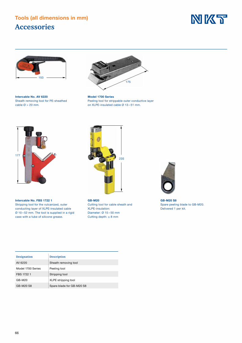
66
AccessoriesTools (all dimensions in mm)
GB-M20Cutting tool for cable sheath and XLPE-insulation: Diameter: Ø 15 – 50 mm Cutting depth: ≤ 8 mm
Intercable No. AV 6220Sheath removing tool for PE-sheathed cable Ø > 20 mm.
Model 1700 SeriesPeeling tool for strippable outer conductive layer on XLPE-insulated cable Ø 13 – 51 mm.
Intercable No. FBS 1722 1Stripping tool for the vulcanized, outer conducting layer of XLPE-insulated cable Ø 10 – 52 mm. The tool is supplied in a rigid case with a tube of silicone grease.
153
235177
175
GB-M20 S8Spare peeling blade to GB-M20. Delivered 1 per kit.
Designation Description
AV 6220 Sheath removing tool
Model 1700 Series Peeling tool
FBS 1722 1 Stripping tool
GB-M20 XLPE stripping tool
GB-M20 S8 Spare blade for GB-M20 S8

67

68
Universal clampsUKR 90, UKRA 90
UKR 90UseFor fixing cables, tubes, hoses, etc. It will fix round profileswith Ø 20 – 90 mm or angular profiles with circumferences of60 – 300 mm.
DesignThe bracket is made of non-magnetic hot-dip galvanizedsteel. The band is made of stainless steel SS 2333-02 withrounded edges and has a thickness of 0.2 mm. The band can be tightened and locked in one operation. The locking bolt is made of die-cast zinc alloy.
UKRS 90Consists of one UKR 90 and a spacer with a hexagon headwood screw for fastening on a wooden pole e.g.
UKRA 90UseFor fixing cables with Ø 20 – 90 mm to the anchor bars in a cable distribution cabinet, etc.
DesignThe bracket is made of non-magnetic hot-dip galvanizedsteel. The band is made of stainless steel according toSS 2333-02 with rounded edges and has a thickness of0.2 mm. The band can be tightened and locked in oneoperation. The locking bolt is made of die-cast zinc alloy.A spring-loaded nut with a reversible locking washer offersa choice of fixed or flexible position and direction.
78
Ø 13
35
90
UKR 90Universal clamp.
UKRS 90Universal clamp with spacer.
UKJEarthing plate.
UKS 90Spacer.
UKRA 90 Universal clamp with bracket for anchor bar.
Dimensional drawing of the anchor bar.
Applications:
Ø 13
35
22 + 0.5– 0
2
41
7
20.5
Designation Weight
kg/item
UKR 90 0.17
UKRA 90 0.23
UKS 0.28
UKRS 90 0.45
UKJ 0.14

69
Universal clampsUKR 200, UKRA 200
UKR 200UseFor bundling cables with Ø 50 – 275 mm.
DesignThe bracket is made of non-magnetic hot-dip galvanizedsteel. The band is made of stainless steel SS 2333-02with rounded edges and has a thickness of 0.2 mm.The band can be tightened and locked in one operation.The locking bolt is made of die-cast zinc alloy.
UKRFFor fixing cables, etc., to cable ladders. For use togetherwith UKR 200. The height of the ladder profile is approx.16 mm and will fit within the specified dimensions.The bracket is made of hot-dip galvanized steel.
UKRS 200Consists of one UKR 200 and a spacer with a hexagonhead wood screw for fastening cables on a wall or awooden pole.
UKRA 200UseFor fixing cables with Ø of 50 – 275 mm to the anchor bars.
DesignThe bracket is made of non-magnetic hot-dip galvanizedsteel. The band is made of stainless steel SS 2333-02with rounded edges and a thickness of 0.2 mm.The locking bolt is made of die-cast zinc alloy and can be tightened and locked in one operation.A spring-loaded nut with a reversible locking washeroffers a choice of fixed or flexible position and direction.
Designation Weight
kg/item
UKR 200 0.32
UKRA 200 0.45
UKRF 0.21
UKRS 200 0.81
UKRA 200 Universal clamp with bracket for anchor bar.
UKRF Fixing bracket.
Dimensional drawing of the anchor bar.
UKR 200Universal clamp.
UKRS 200Universal clamp UKR 200 with spacer.
55
21
13
55
78
22 + 0.5– 0
2
41
7
20.5
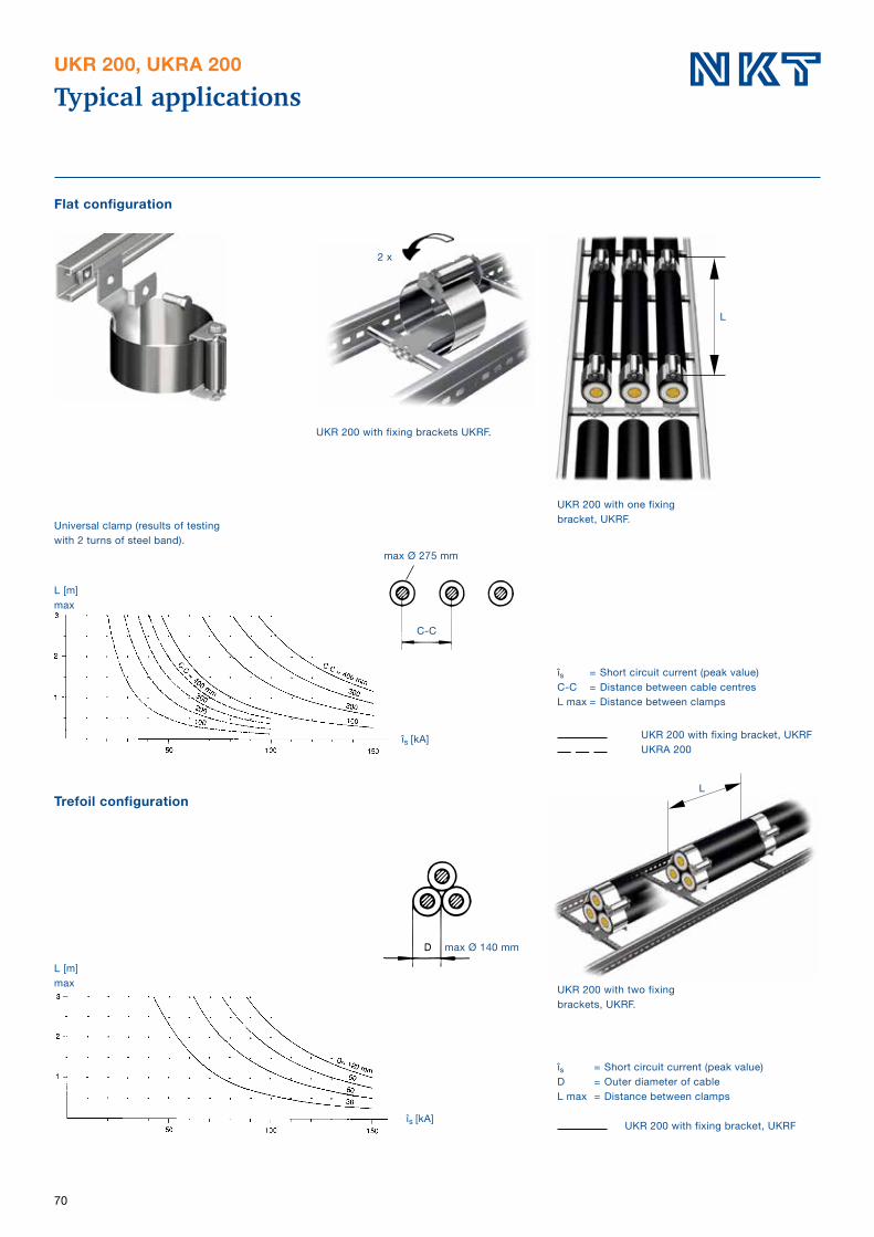
70
Typical applicationsUKR 200, UKRA 200
Universal clamp (results of testing with 2 turns of steel band).
UKR 200 with fixing brackets UKRF.
UKR 200 with one fixing bracket, UKRF.
Flat configuration
L
max Ø 275 mm
L [m]max
îs [kA]
îs = Short circuit current (peak value)C-C = Distance between cable centresL max = Distance between clamps
UKR 200 with fixing bracket, UKRF UKRA 200
Trefoil configuration
îs = Short circuit current (peak value)D = Outer diameter of cableL max = Distance between clamps
UKR 200 with fixing bracket, UKRF
L
UKR 200 with two fixing brackets, UKRF.
max Ø 140 mm
L [m]max
îs [kA]
2 x
C-C

71

72
List of contentAlphabetical order
Designation Page No.
A
A-TBF SKR 51
ADAPTER 17
APED 12–36 kV 52
APIT 12–36 kV 49
APSEA 12–36 kV 50–51
ARM 58
AV 6220 66
C
CSAP-A 12–24 kV 37
CSE-A 12–24 kV, 250 A 26–28
CSE-A 12–42 kV, 400 A 29-30
CSE-A 12–42 kV, 630 A 31-33
CSEP-A 12–42 kV 34-36
CU 250 27
CW 60
F
FBS-1722 1 66
FK 59
FKFB 59
G
GAP-APED 53
GB-M20 66
GB-M20 S8 66
H
HDC-A 250 A, 12–24 kV 22–23
HDC-A 630 A, 12–36 kV 24–25
HU 150 61
HU 200 61
HUF 61
HUS 61
I
IA 1701 64
IA 1706 64
IA 2333 62
IA 2337 62
IA 2338 62
IA 2339 62
IA 2342 62
IA 2343 62
IA 2352 62
Designation Page No.
I
IA 2362 62
IA 2421 62
IA 2441 62
IA 2443 62
IA 2444 62
IH-A 24250 28
IH-A 24400 30
IH-A 24630 33
IH-A 42400 30
IH-A 42630 33
IK 1105, 1106, 1107, 1108, 1109 63
IK 1401 63
IK 1405 63
IK 1406 63
IK 1407 63
IK 1502 63
IK 2221 63
IK 2230 64
IK 2233 63
IP 250 28
IP 400 30
IP 630 33
J
JP 250 28
JPB 630 33
JPA V 33
JSA 4–6 56
JSA 10–16 57
JXT 1–3 56
K
KA 250 23
KA 630 25
K-TBF 30 SKR 51
K-TBF 40 SKR 51
KAP 300 U 41
KAP 630 39
M
MA 250 28
MA-A 630 33
MBR 250 64
Model 1700 Series 66

73
List of contentAlphabetical order
Designation Page No.
P
PC 630-3 33
PC 630-3 L 33
PC 630/250 28, 33
PG 630 33
PG-A 630 33
PIU-APED 53
PSSK 54
PSSK E 54
PSSK L 54
R
RKM 1435 65
RKM 2550 65
RKM 670 65
RKM 672 65
RKM-SB 65
RKS 1607 054 65
RULLE 62
S
730 R 65
SC-B 60
SCL-B 60
SH-SKRM 60
SKALUS 64
SMXB 20–21
SOJ 11–19
SOT 43–48
SSH 55
STOP 17–21
Designation Page No.
T
TB-A 12 38
THS, THSA 51
TS 17
TSH 55
U
UKJ 68
UKR 90 68
UKR 200 69
UKRA 90 68
UKRA 200 69
UKRF 69
UKS 90 68
UKRS 90 68
UKRS 200 69
W
WIM 18, 21

74

75
List of content by categoryCable terminations, cable connectors and cable joints
Cable Joints See page
12–36 kVXLPE- and EPR-insulated cable
Premolded SOJ 12–36 11–19
Tape SMXB 12–36 20–21
12–36 kV Cable distribution cabinet
12–36 kV Cabledistribution cabinet
Cable cabinet, 250 A HDC-A 12–24 kV 22–23
Cable cabinet, 630 A HDC-A 12–36 kV 24–25
12–24 kV XLPE- and EPR-insulated cable Premolded screened separable connector CSE-A 250 A 26–28
36–42 kV XLPE- and EPR-insulated cable Premolded screened separable connector CSE-A 400 A 29–30
36–42 kV XLPE- and EPR-insulated cable Premolded screened separable connector CSE-A 630 A 31–33
12–42 kV XLPE- and EPR-insulated cable Premolded parallel screened separable connector CSEP-A 630 A 34–36
12–24 kV XLPE- and EPR-insulated cable Premolded screened separable surge arrestor CSAP-A 630 A 37
Shrouded terminations
12–24 kV XLPE- and EPR-insulated cable
Shrouded termination, 12 kV indoor TB-A 38
Shrouded termination, 12–24 kV indoor KAP 630, 630 A 39–40
Shrouded termination, 12–24 kV indoor KAP 300 U, 300 A 41–42
Cable terminations
10–36 kV XLPE- and EPR-insulated cable Premolded indoor/outdoor SOT 10–36 kV 43–48
12–36 kV XLPE- and EPR-insulated cable
Premolded, with geometrical field control, indoor APIT 12–36 kV 49
Premolded, with geometrical field control, outdoor APSEA 12–36 kV 50–51
Composite, with geometrical field control, indoor and outdoor APED 36 kV 52–53
Accessories
Accessories for XLPE- and EPR-insulatedCable accessories12–36 kV
Screen separation kit PSSK, PSSK-E, PSSK L 54
Branch seal for 3-core cable terminations TSH, SSH 55
Earthing kit for terminations JSA 4–6 and JXT 1–3 56
Screen connection for joints JSA 10–16 57
Armouring kit ARM 58
Overhead line clamp FK 120 och FK 300 59
Bolt cable lug SCL-B 60
Bolt connector SC-B 60
Bolt connector SH-SKRM 60
General accessories 12–36 kV
Bird protection 61
Tapes 62
Other accessories 63–64
Tools 65–66
General accessories Universal clamps
UKR 90 68
UKRA 90 68
UKR 200 69
UKRA 200 69

®
NKT is signatory of the Europacable Industry Charter: A commitment towards superior quality.
NKT HV Cables ABSävelundsgatan 2 441 16 Alingsås Sweden
Tel: +46 322 774 00
Note: We reserve the right to make technical changes or modify the content of this document without prior notice. With regard to purchase orders, the agreed particulars shall prevail. NKT does not accept any responsibility whatsoever for potential errors or possible lack of information in this document. We reserve all rights in this document and in the subject matter and illustrations contained therein. Any reproduction, disclosure to third parties or utilization of its contents – in whole or in parts – is forbidden without prior written consent of NKT.
Copyright © 2018 NKTAll rights reserved
CAT
enBB
1801
0115
T
he N
KT lo
go is
a re
gist
ered
trad
emar
k of
NKT
Gro
up A
/S. ©
2017
NKT
Gro
up A
/S. A
ll rig
hts
rese
rved
.