16023510 maytag jenn-air jxt vent hoods
DESCRIPTION
JXT5830ADB/W/SJXT5836ADB/W/SJXT6030ADSJXT6036ADSJXT8030ADSJXT8036ADSJXT8042ADSJXT8136ADSJXT8142ADSJXT9030CDPJXT9036CDPJXT9048CDPJXT9130CDPJXT9136CDPTRANSCRIPT

JXT5830ADB/W/SJXT5836ADB/W/SJXT6030ADSJXT6036ADSJXT8030ADSJXT8036ADSJXT8042ADSJXT8136ADSJXT8142ADSJXT9030CDPJXT9036CDPJXT9048CDPJXT9130CDPJXT9136CDP
16023510November 2004
©2004 Maytag Services
Vent Hoods
This Base Manual covers general information
Refer to individual Technical Sheetfor information on specific models
This manual includes, but isnot limited to the following:
ServiceThis manual is to be used by qualified appliancetechnicians only. Maytag does not assume anyresponsibility for property damage or personalinjury for improper service procedures done byan unqualified person.

2 16023510 ©2004 Maytag Services
Pride and workmanship go into every product to provide our customers with quality products. It is possible, however,that during its lifetime a product may require service. Products should be serviced only by a qualified servicetechnician who is familiar with the safety procedures required in the repair and who is equipped with the proper tools,parts, testing instruments and the appropriate service information. IT IS THE TECHNICIANS RESPONSIBILITY TOREVIEW ALL APPROPRIATE SERVICE INFORMATION BEFORE BEGINNING REPAIRS.
Important Notices for Servicers and Consumers
! WARNINGTo avoid risk of severe personal injury or death, disconnect power before working/servicing on appliance to avoidelectrical shock.
To locate an authorized servicer, please consult your telephone book or the dealer from whom you purchased thisproduct. For further assistance, please contact:
Customer Service Support Center
CAIR CenterWeb Site Telephone Number
WWW.JENNAIR.COM ............................................. 1-800-688-1100CAIR Center in Canada ........................................... 1-800-688-2002
Recognize Safety Symbols, Words, and Labels
DANGER!DANGER—Immediate hazards which WILL result in severe personal injury or death.
WARNING!WARNING—Hazards or unsafe practices which COULD result in severe personal injury or death.
CAUTION!CAUTION—Hazards or unsafe practices which COULD result in minor personal injury, product or property
damage.
Important Information

©2004 Maytag Services 16023510 3
Table of ContentsImportant Information .................................................... 2Important Safety Information
In Case of Fire .......................................................... 4Safety Practices for Servicer .................................... 4Servicing .................................................................. 4Electrical Requirements ........................................... 5Extension Cord ........................................................ 5Receiving Vent Hood ................................................ 5Precautions .............................................................. 5Using the Vent Hood ................................................ 5
General InformationCooking Nomenclature ............................................. 6Specifications .......................................................... 7Placement of the Vent Hood .................................... 7Do Not Block Air Vents ............................................ 7Location of Model Number ........................................ 7Grounding Instructions ............................................. 7Model Identification .................................................. 7Service ..................................................................... 7Parts and Accessories ............................................. 7Extended Service Plan ............................................. 7Vent Hood Description ............................................. 8
Troubleshooting Procedures ......................................... 9Testing Procedures ......................................................11
Disassembly Procedures for Models JXT9030CDP,JXT9036CDP, JXT9048CDP, JXT9130CDP, JXT9136CDP
Halogen Light Removal ............................................ 13Heat Lamp Removal ................................................ 13Grease Filter/Grease Filtger Cover Removal............ 13Halogen Light Socket ..............................................13Heat Lamp Socket Removal .................................... 13Light Panel Removal ............................................... 14Control Board Removal ............................................ 14Touch Pad Removal ................................................ 14Capacitor Removal .................................................. 14Transformer Removal ............................................... 15Blower Motor Removal ............................................ 15Filter Spring Clip Removal ....................................... 15
Disassembly Procedures for Models JXT8042ADS,JXT8142ADS, JXT58309AD*, JXT5836AD*
Halogen Light Removal ............................................ 16Grease Filter/Grease Filtger Cover Removal............ 16Halogen Light Socket ..............................................16Control Board Removal ............................................ 16Control Panel Removal ............................................ 17Blower Motor Removal ............................................ 17Capacitor Removal .................................................. 17Filter Spring Clip Removal ....................................... 17
Appendix A: Installation InstructionsJXT5830AD*, JXT5836AD* ..................................... A-2JXT8030ADS, JXT8036ADS, JXT8048ADS ............ A-4JXT8136ADS, JXT8142ADS ................................... A-6JXT9030CDP, JXT9036CDP, JXT9048CDP ............ A-8JXT9130CDP, JXT9136CDP ................................. A-10
Appendix B: Controls and FeaturesJXT5830AD*, JXT5836AD*, JXT8030ADS,JXT8036ADS, JXT8048ADS, JXT8136ADS,JXT8142ADS ......................................................... B-2JXT9030CDP, JXT9036CDP, JXT9048CDP,JXT9130CDP, JXT9136CDP ................................... B-5Care and Cleaning ................................................. B-6

4 16023510 ©2004 Maytag Services
WARNING!
In Case of FireFires can occur as a result of over cooking or excessivegrease. Though a fire is unlikely, proceed as follows:
Surface Element Fires
1. Smother fire with a nonflammable lid/baking soda,or use a Class ABC or BC extinguisher. Notwater, salt or flour.
2. As soon as it is safe to do so, turn the surfacecontrols to “OFF."
Oven Fires
1. Do not open the oven door.2. Turn all range/oven controls to the OFF position.3. As an added precaution turn off oven/range
electricity at the main circuit breaker or fuse box.4. Turn on vent hood to remove smoke.5. Allow the food or grease to burn itself out in the
oven.6. If smoke and fire persist, call the local fire
department.7. If there is any damage to components, call an
authorized servicer before using the vent hood.
To avoid risk of property damage or personal injury, donot obstruct the flow of ventilation air to the vent hood.
To avoid risk of electrical shock, serious personal injuryor death: Verify the vent hood has been properlygrounded and always disconnect the electrical supplybefore servicing this unit.
Safety Practices for ServicerSafe and satisfactory operation of vent hoods dependsupon its design and proper installation.
ServicingListed below are some general precautions and safetypractices which should be followed in order to protectthe service technician and consumer during service andafter service has been completed.
1. Check vent hood when service is complete—Afterservicing, make visual checks on electricalconnection. Inform consumer of the condition of venthood before leaving.
2. Adhere to all local regulations and codes whenperforming service.
Recognize this symbol as a safety precaution.
!
WARNING!If the information in this manual is not followed exactly,a fire or explosion may result causing propertydamage, personal injury or death.
There can be a risk of injury or electrical shock whileperforming services or repairs. Injury or electricalshock can be serious or even fatal. Consequently,extreme caution should be taken when performingvoltage checks on individual components of a product.The electrical power supply should ALWAYS bedisconnected when servicing a product.
This appliance must be properly grounded. Never plugin or direct-wire an appliance unless it is properlygrounded and in accordance with all local and nationalcodes. See "Installation Instructions" that accompanythe product for the appropriate grounding procedures.
WARNING!To avoid risk of electrical shock, property damage,personal injury or death; verify wiring is correct, ifcomponents were replaced. Verify proper and completeoperation of unit after servicing.
This appliance contains or produces a chemical orchemicals which are known to the state of California tocause cancer, birth defects or other reproductive harm.To reduce the risk from substances in the fuel or fromfuel combustion, make sure this appliance is installed,operated, and maintained according to the instructionsin this manual.
Important Safety Information
©2004 Maytag Services 16023510 5
Electrical Requirements120-volt, 60 Hertz, 40 amp, individual circuit which isproperly grounded, polarized and protected by a circuitbreaker or fuse.
Extension CordDue to possible pinching during installation, extensioncords should not be used on products.
Receiving the Vent Hood• Authorized servicer must install the vent hood, in
accordance with the Installation Instructions.• Adjustments and service should be performed only by
authorized servicer.• Plug vent hood into a 120–volt grounded outlet only.• Do not remove round grounding prong from the plug. If
in doubt about grounding of the home electricalsystem, it is consumers responsibility and obligation tohave an ungrounded outlet replaced with a properlygrounded three-prong outlet in accordance with theNational Electrical Code.
• Do not use an extension cord with this vent hood.• Insure all packing materials are removed from the vent
hood before operating.• Clean grease and dirt from exisiting duct work to
prevent future fires.• Check all joints on duct work to ensure proper
connection; all joints should be taped properly.
Precautions• When cutting or drilling into walls or ceilings, do not
damage electrical wiring and other hidden utilitites.• Ducted fans must always be vented to the outdoors.• Clean vent hood frequently. Grease should not be
allowed to accumulate on hood or filter.• When flaming foods under the hood, turn the fan off.
The fan, if operating, may spread the flame.• Do not mix household cleaning products. Chemical
mixtures may interact with hazardous results.
Using the Vent Hood• Do not allow anyone to climb, stand or hang on the
vent hood. They could damage the vent hood andcause severe personal injury.
• Saturation of greasy residue in the blower and filtersmay cause increased flammability. Keep vent hoodclaen and free of grease and residue build-up at alltimes to prevent possible fires.
• Filters must be cleaned periodically and kept free fromaccumulation of cooking residue.
• Old and worn filters must be replaced immediately.• Do not operate blowers when filters are removed.• Do not disassemble parts (for cleaning) without proper
instructions. Contact the Service Center for removalinstructions at (800) 536-6247.
• Do not use water on grease fires.• Do not let grease or other flammable materials collect
in or around the vent hood.• Do not repair or replace any part of the vent hood
unless it is recommended in this manual.• Keep vent hood ducts unobstructed.
CAUTION!Do not store items of interest to children in cabinetsabove the vent hood. Children may climb on the venthood to reach these items and may become seriouslyinjured.
Important Safety Information

6 16023510 ©2004 Maytag Services
This manual contains information needed by authorizedservice technicians to install and service electric venthoods. There may be, however, some parts which needfurther explanation. Refer to the Installation Instructions,Use and Care, Technical Sheets or the toll-free technicalsupport line.
This manual provides basic instructions and suggestionsfor handling, installing and servicing electric vent hoods.
The directions, information, and warnings in this manualare developed from experience and careful testing of theproduct. If the unit is installed according to this manual, itwill operate properly and will require minimal servicing. Aunit in proper operating order ensures the consumer allthe benefits provided by the electric vent hood.
General Information
Cooking Nomenclature
J X T 9 1 3 6 C D P
Brand A Amana C Magic Chef G Graffer &
Sattler H Hardwick J Jenn-Air M Maytag N Norge U Universal Y Crosley
Product Type A Accessory/Cartridge C Cooktop Updraft/Countertop D Downdraft Cooktop or Warming Drawer E Eyelevel Range G Grill L Range (20") M Range (36") P Drop In (24") Q Wall Oven (27") R Range, Free-Standing (30") S Slide-In (30") T Range Hood V OTR W Wall Oven Y RV Range Z RV Top
Fuel B Butane D Dual Fuel
E/J Electric G Gas, Natural L Liquid Propane M Microwave P Standing Pilot X No Fuel W Warming Drawer
Listing A UL/AGA C CSA/CGA/CUL D Dual Listed G 220-240 V / 50-60 Hz M Military Model P PSB Approved
(Singapore) X Export 120 V / 60 Hz
Feature Content 1000-3999 Brands 4000-6999 Maytag/Amana 7000-9999 Jenn Air
Production Code This identifies the production version.
Color A Almond on Almond B Black C Brushed Chrome H Traditional White L Traditional Almond P Prostyle Q Monochromatic Bisque S Stainless T Traditional Bisque W White on White F Frost White (True Color White) N Natural Bisque (True Color Bisque)

©2004 Maytag Services 16023510 7
SpecificationsRefer to individual Technical Sheet for specificationinformation.
Placement of the Vent HoodThis electric vent hood must be placed in the kitchen orcomparable room. All safety guidelines must be followed(see Chapter 2) and free air flow around the vent hood isessential.
Do Not Block Air VentsAll air vents must be kept clear during cooking. If airvents are covered during operation, the vent hood mayoverheat.
Location of Model NumberTo request service information or replacement parts, theservice center will require the model number of your venthood. This number can be found inside or under the venthood shroud.
Grounding InstructionsThis vent hood must be grounded. If an electrical shortcircuit occurs, grounding reduces the risk of electricshock by providing an escape wire for the electric current.The cord for this vent hood has a grounding wire with agrounding plug. Put the plug into an outlet that is properlyinstalled and grounded.
WARNING!To avoid risk of electric shock, personal injury or death,use grounding plug properly.
Ask a qualified electrician if you do not understand thegrounding instructions or if you wonder whether the venthood is properly grounded.Keep the electrical power cord dry and do not pinch orcrush it in any way.
General InformationFor a permanently connected vent hood: This vent hoodmust be connected to a grounded, metallic, permanentwiring system, or an equipment grounding conductorshould be run with the circuit conductors and connectedto the equipment grounding terminal or lead on theappliance.
WARNING!Attaching adapter ground terminal to wall receptaclecover screw does not ground the vent hood unless thecover screw is metal and not insulated, and wallreceptacle is grounded through the house wiring.Consumer should have circuit checked by a qualifiedelectrician to verify receptacle is properly grounded.
Model IdentificationComplete enclosed registration card and promptly return.If registration card is missing:• For Jenn-Air product call 1-800-688-1100 or visit the
Web Site at www.jennair.com• For product in Canada call 1-866-587-2002 or visit the
Web Site at www.jennair.comWhen contacting provide product information located onrating plate. Record the following:Model Number: ___________________Manufacturing Number: ___________________Serial or S/N Number: ___________________Date of purchase: ___________________Dealer’s name and address: ___________________
ServiceKeep a copy of sales receipt for future reference or incase warranty service is required. To locate an authorizedservicer:• For Jenn-Air product call 1-800-688-1100 or visit the
Web Site at www.jennair.com• For product in Canada call 1-866-587-2002 or visit the
Web Site at www.jennair.comWarranty service must be performed by an authorizedservicer. We also recommend contacting an authorizedservicer, if service is required after warranty expires.
Parts and AccessoriesPurchase replacement parts and accessories over thephone. To order accessories for your product call:• For Jenn-Air product call 1-800-688-1100 or visit the
Web Site at www.jennair.com• For product in Canada call 1-866-587-2002 or visit the
Web Sites at www.amana.com or www.maytag.com
Extended Service PlanWe offer long-term service protection for this new oven.• Dependability PlusSM Extended Service Plan is
specially designed to supplement Jenn-Air’s strongwarranty. This plan covers parts, labor, and travelcharges.Call 1-800-925-2020 for information.

8 16023510 ©2004 Maytag Services
Range Description
Vent Hood Description
Touch Pad/Control Pad
Heat Lamps
Halogen Lights
Filters/Filter Covers
Blower Motor
Touch Pad/Control Pad
Halogen Lights
Filters/Filter Covers(in vent hood)
Blower Motor(in vent hood)

Troubleshooting Procedures
! WARNING
To avoid risk of electrical shock, personal injury, or death, disconnect power to vent hood before servicing, unless testing requires power.
©2004 Maytag Services 16023510 9
Problem Possible Cause Correction Blower motor will not operate, lights will not illuminate
No input power ................................................Circuit breaker tripped.....................................Black/white or white wires loose at control board, no wires connected to control board....Control board defective ...................................Touch pad/control panel defective ..................
• Verify 120 VAC is present at unit. • Verify circuit breaker isn’t tripped.
• Verify all connections are tight. • Perform control board test. • Perform touch pad or control
panel test. Blower motor will not operate(Lights illuminate)
Blue wire loose on control board..................... Blower motor seized........................................ Blower motor defective....................................Capacitor damaged or defective .....................Touch pad or control panel defective..............Blower motor too hot and has been shut down by the thermal protection system...........
• Verify blue wire is connected and tight on control board.
• Verify blower is free from obstructions and rotates freely.
• Perform blower motor test. • Perform capacitor test. • Perform touch pad or control
panel test. • Allow blower motor to cool.
Blower motor starts slow and will not operate at full speed (Lights illuminate)
Capacitor shorted or defective ........................Blower motor defective....................................Control board defective ...................................Touch pad or control panel defective.............. Obstructions in blower motor ..........................
• Perform capacitor test. • Perform blower motor test. • Perform control board test. • Perform touch pad or control
panel test. • Verify blower motor is free from
obstructions and rotates freely. Blower motor operates, but cannot change fan speed (Lights illuminate)
Capacitor shorted or defective ........................Blower motor defective....................................Touch pad or control panel defective.............. Obstructions in blower motor ..........................
• Perform capacitor test. • Perform blower motor test. • Perform touch pad or control
panel test. • Verify blower motor is free from
obstructions and rotates freely. Lights will not illuminate (Blower motor operates)
Light bulb(s) burnt out .....................................Light bulb not making contact with socket ...... Red wire loose on control board ..................... Touch pad or control panel defective.............. Light socket defective......................................
• Replace bulb(s). • Remove power to unit, remove
light bulb and bend the two metal brackets inside the bulb opening (bend outwards). This lowers the light socket.
• Verify red wire is connected and tight on control board.
• Perform touch pad or control panel test.
• Perform halogen light test.
Lights illuminate at full brightness only (Blower motor operates)
Loose wires to lights/control board.................. Light socket defective......................................Control board defective ...................................Control panel defective ...................................Touch pad or control panel defective..............
• Verify wires are connected and tight at light socket/control board.
• Perform halogen light test. • Perform control board test. • Replace control panel. • Perform touch pad or control
panel test.

Troubleshooting Procedures
! WARNING
To avoid risk of electrical shock, personal injury, or death, disconnect power to vent hood before servicing, unless testing requires power.
10 16023510 ©2004 Maytag Services
Problem Possible Cause Correction
Lights illuminate at half brightness only (Blower motor operates)
Loose wires to lights/control board................. Light socket defective.....................................Control board defective ..................................Control panel defective...................................Touch pad or control panel defective .............
• Verify wires are connected and tight at light socket/control board.
• Perform halogen light test. • Perform control board test. • Perform control panel test. • Perform touch pad or control
panel test. Vent hood vibrates when operating blower motor
Blower motor loose.........................................Blower motor wheel damaged........................Vent hood not securely fastened....................
• Tighten blower motor. • Replace blower motor wheel. • Verify vent hood installation;
tighten as necessary. Metal filter vibrates when operating blower motor
Metal filter loose .............................................Broken clip......................................................
• Tighten or change metal filter. • Replace the clip.
Display will not illuminate No input power ...............................................Circuit breaker tripped ....................................Loose wire connection or broken wire............ Control board defective .................................. Touch pad or control panel defective .............
• Verify 120 VAC is present at unit. • Verify circuit breaker isn’t tripped.• Verify all connections are clean
and tight, wires are not broken. • Verify voltage is present. If so,
perform control board test. • Perform touch pad or control
panel test. Heat lamp will not illuminate Heat lamp bulb defective................................
No input power ...............................................Circuit breaker tripped ....................................Loose wire connection or broken wire............ Touch pad or control panel defective .............
• Replace heat lamp bulb. • Verify 120 VAC is present at unit. • Verify circuit breaker isn’t tripped.• Verify all connections are clean
and tight, wires are not broken. • Perform touch pad or control
panel test. Dim display Loose wire connection or broken wire............
Control board requires a reset........................ Control board defective .................................. Touch pad or control panel defective .............
• Verify all connections are clean and tight, wires are not broken.
• Disconnect power to unit for 15 minutes. If still dim, replace the control board.
• Verify voltage is present. If so, test control board.
• Perform touch pad or control panel test.
Any one single function on control panel does not operate
Touch pad or control panel defective ............. • Perform touch pad or control panel test.
Vent hood not venting properly
Vent hood not close enough to cooktop......... Open doors/windows affecting air flow........... Ductwork clogged or blocked .........................Duct opening restricted ..................................Ductwork too small .........................................
• Verify distance between hood and cooktop (24-32 inches).
• Close all nearby doors and windows.
• Clean the ductwork. • Adjust the duct opening direction.• Increase size of ductwork.

Testing Procedures
! WARNING To avoid risk of electrical shock, personal injury or death; disconnect power to vent hood before servicing, unless testing requires power.
©2004 Maytag Services 16023510 11
Model Numbers Component Test Procedure Results
All Halogen lights Press light switch once.................................(measure voltage at light socket)..................Press light switch again ................................(measure voltage at light socket)..................Press light switch once.................................(measure voltage at light socket)..................Press and hold light switch for 3 seconds.....(measure voltage at light socket)..................
Lights illuminate to full brightness (120 VAC). Lights extinguish (turn off) (0 VAC). Lights illuminate to full brightness (120 VAC). Lights illuminate to half brightness (63 VAC)
All Halogen light socket Remove one wire from receptacle and test resistance of terminals..................................Measure voltage at light ...............................
Indicates continuity with bulb screwed in.120 VAC. If no voltage is present at light, check wiring or light switches.
JXT9030CDP, JXT9036CDP, JXT9048CDP, JXT9130CDP, JXT9136CDP
Heat lamp socket Remove one wire from receptacle and test resistance of terminals..................................Measure voltage at light ...............................
Indicates continuity with bulb screwed in.120 VAC. If no voltage is present at light, check wiring or light switches.
JXT8030ADS, JXT8036ADS, JXT8042ADS, JXT8136ADS, JXT8142ADS, JXT5830AD*, JXT5836AD*
Capacitor Disconnect wires. Measure resistance by placing red meter lead on positive terminal, black meter lead on negative terminal ........................................................ Reverse meter leads on capacitor terminals.......................................................Check for a short by placing one lead on a terminal and the other to ground...................
Meter reading should gradually increase (capacitor charging). Meter reading should gradually decrease (capacitor discharging). Infinity (if shorted, replace capacitor).
JXT9030CDP, JXT9036CDP, JXT9048CDP, JXT9130CDP, JXT9136CDP
Capacitors (2 ea, red wires input, yellow wires output)
Obtain analog multi-meter. Disconnect wires. Measure resistance by placing red meter lead on positive terminal, black meter lead on negative terminal ................... Reverse meter leads on capacitor terminals.......................................................Check for a short by placing one lead on a terminal and the other to ground...................
Rating: 4 microfarad Meter reading should gradually increase (capacitor charging). Meter reading should gradually decrease (capacitor discharging). Infinity (if shorted, replace capacitor).
JXT8030ADS, JXT8036ADS, JXT8042ADS, JXT8136ADS, JXT8142ADS, JXT5830AD*, JXT5836AD*
Transformer Check for input voltage by placing red lead on black wire (input voltage), black lead on white wire (neutral)...........................Check transformer outputs by placing leads on black (input voltage) and white (neutral), then set fan speed as follows: 6 ...................................................................5 ...................................................................4 ...................................................................3 ...................................................................2 ...................................................................1 ...................................................................
120 VAC 113 VAC 88 VAC 80 VAC 66 VAC 50 VAC 33 VAC
JXT9030CDP, JXT9036CDP, JXT9048CDP, JXT9130CDP, JXT9136CDP
Transformer Check for input voltage by placing red lead on brown wire (input), black lead on light blue wire (neutral) .................................Check transformer outputs by placing meter leads on: Brown (Input voltage) ...................................Black ............................................................Red...............................................................Orange .........................................................Yellow...........................................................Green (Lowest setting) .................................
120 VAC 120 VAC 106 VAC 97 VAC 90 VAC 81 VAC 74 VAC

Testing Procedures
! WARNING To avoid risk of electrical shock, personal injury or death; disconnect power to vent hood before servicing, unless testing requires power.
12 16023510 ©2004 Maytag Services
Model Numbers Component Test Procedure Results
JXT8030ADS, JXT8036ADS, JXT8042ADS, JXT8136ADS, JXT8142ADS, JXT5830AD*, JXT5836AD*
Blower Motor Check input voltage by placing leads on screws in green connector, black wire terminal (input voltage) and white wire terminal (neutral)..........................................Measure resistance......................................
120 VAC 12 Ω (if under 3 Ω, motor windings shorted. If over 3 Ω but under 7 Ω, capacitor shorted.)
JXT9030CDP, JXT9036CDP, JXT9048CDP, JXT9130CDP, JXT9136CDP
Blower Motor Check input voltage by placing leads on light blue wire terminal (input voltage) and black wire terminal (neutral) .........................Measure resistance......................................
120 VAC 16 Ω through both motors
JXT8030ADS, JXT8036ADS, JXT8042ADS, JXT8136ADS, JXT8142ADS, JXT5830AD*, JXT5836AD*
Control Board Measure input voltage by placing leads on screws in green connector, black wire terminal (input voltage) and white wire terminal (neutral)..........................................
120 VAC
JXT9030CDP, JXT9036CDP, JXT9048CDP, JXT9130CDP, JXT9136CDP
Control Board Measure input voltage by placing meter leads on black/white wire (input voltage) and white wire (neutral)................................
120 VAC
JXT8030ADS, JXT8036ADS, JXT8042ADS, JXT8136ADS, JXT8142ADS, JXT5830AD*, JXT5836AD*
Control Panel Measure input voltage by placing leads on screws in green connector, black wire terminal (input voltage) and white wire terminal (neutral)..........................................
120 VAC, if not, replace Control Panel
JXT9030CDP, JXT9036CDP, JXT9048CDP, JXT9130CDP, JXT9136CDP
Touch Pad Pin 1 = Black wire, Pin 2 = Brown wire, Pin 3 = Red wire, Pin 4 = Orange wire, Pin 5 = Yellow wire, Pin 6 = Green wire, Pin 7 = Blue wire, Pin 8 = Violet wire
Remove multi-colored display cable from control board, place meter leads on the applicable pins, press the applicable pad and measure resistance. Pins 2 & 5, turn on Light On/Off..................Pins 2 & 6, turn on Fan On/Off ....................Pins 3 & 5, press & hold Fan Speed +.........Pins 3 & 6, press & hold Fan Speed -..........Pins 4 & 5, press & hold Delay Off ..............
Continuity Continuity Continuity Continuity Continuity

©2004 Maytag Services 16023510 13
WARNING! To avoid risk of electrical shock, personal injury ordeath; disconnect power to unit before servicing.
Disassembly Procedures
Halogen Light Socket Removal1. Disconnect power to vent hood.2. Remove halogen light, see "Halogen Light Removal"
procedure.3. Remove grease filters and covers, see "Grease Filter/
Grease Filter Cover Removal" procedure.4. Remove light panel, see "Light Panel Removal"
procedure.5. Remove screws securing light socket and remove
light socket.6. Reverse procedure to reinstall light socket.
Heat Lamp Socket Removal1. Disconnect power to vent hood.2. Remove heat lamp, see "Heat Lamp Removal"
procedure.3. Remove grease filters and covers, see "Grease Filter/
Grease Filter Cover Removal" procedure.4. Remove screw securing electrical connector cover.5. Label and disconnect heat lamp socket electrical
connection.6. Remove screws securing lamp reflector.7. Remove screws securing lamp socket and remove
lamp socket.9. Reverse procedure to reinstall lamp socket.
Disassembly for models JXT9030CDP,JXT9036CDP, JXT9048CDP, JXT9130CDP,JXT9136CDP
Halogen Light Removal1. Turn off power to the light bulb.2. Twist light bulb counterclockwise from the socket.
NOTE: A suction cup may be required for light bulbremoval. One may be obtained from a localhardware store.
3. Reverse procedure to reinstall light bulb.
Heat Lamp Removal1. Turn off power to the heat lamp.2. Twist heat lamp counterclockwise from the socket.
NOTE: A suction cup may be required for heat lampremoval. One may be obtained from a localhardware store.
3. Reverse procedure to reinstall heat lamp.
Grease Filter/Grease Filter Cover Removal1. Turn off power to the blower motors.2. Remove grease filter covers by using handles and
pulling filter cover toward the rear of the vent hood.3. Pivot front of grease filter upward, then pull the filter
downwards and toward the rear to remove.4. Reverse procedure to reinstall grease filters and
grease filter covers.

14 16023510 ©2004 Maytag Services
WARNING! To avoid risk of electrical shock, personal injury ordeath; disconnect power to unit before servicing.
Disassembly Procedures
Capacitor Removal1. Disconnect power to vent hood.2. Remove grease filters and covers, see "Grease Filter/
Grease Filter Cover Removal" procedure.3. Remove light panel, see "Light Panel Removal"
procedure.4. Discharge capacitor by connecting a one end of a
jumper wire to the capacitor terminal with the diodeconnection and the other end to a well insulatedscrewdriver. Touch the screwdriver to a chassisground. Remove jumper wire.
5. Remove screws securing capacitor.6. Label and disconnect capacitor electrical connections
and remove capacitor.7. Reverse procedure to reinstall capacitor.
Light Panel Removal1. Disconnect power to vent hood.2. Remove grease filters and covers, see "Grease Filter/
Grease Filter Cover Removal" procedure.3. Remove screws securing light panel.NOTE: Some screws are located on top of light panel.4. Remove screws securing blower motor cover.5. Label and disconnect fan switch wires.6. Remove light socket, see "Light Socket Removal"
procedure.7. Angle the light panel slightly and gently pull down to
remove from vent hood.8. Reverse procedure to reinstall light panel.
Control Board Removal1. Disconnect power to vent hood.2. Remove grease filters and covers, see "Grease Filter/
Grease Filter Cover Removal" procedure.3. Remove screws securing light panel.4. Slide panel towards rear of vent hood.5. Remove light panel, see "Light Panel Removal"
procedure.6. Label and disconnect control board wiring and
remove control board.7. Reverse procedure to reinstall control board.
Touch Pad Removal1. Disconnect power to vent hood.2. Remove grease filters and covers, see "Grease Filter/
Grease Filter Cover Removal" procedure.3. Remove light panel, see "Light Panel Removal"
procedure.4. Remove screws securing touch pad.5. Label and disconnect touch pad electrical
connections.6. Rotate and remove touch pad from base.7. Reverse procedure to reinstall touch pad.

©2004 Maytag Services 16023510 15
WARNING! To avoid risk of electrical shock, personal injury ordeath; disconnect power to unit before servicing.
Disassembly Procedures
Transformer Removal1. Disconnect power to vent hood.2. Remove grease filters by using handles and pulling
filter toward the rear of the vent hood.3. Pivot front of filter upward, then pull the filter
downwards and toward the rear to remove.4. Remove light panel, see "Light Panel Removal"
procedure.5. Discharge capacitor by connecting a one end of a
jumper wire to the capacitor terminal with the diodeconnection and the other end to a well insulatedscrewdriver. Touch the screwdriver to a chassisground. Remove jumper wire.
6. Remove screws securing transformer.7. Label and disconnect transformer electrical
connections.8. Remove transformer.9. Reverse procedure to reinstall transformer.
Blower Motor Removal1. Disconnect power to vent hood.2. Remove grease filters and covers, see "Grease Filter/
Grease Filter Cover Removal" procedure.3. Remove screws securing blower motor covers.4. Remove blower wheel hub assembly.5. Loosen set screws and remove blower motor wheel.6. Remove screws securing blower motor to vent hood.7. Label and disconnect blower motor electrical
connections.8. Rotate blower motor counterclockwise to remove.9. Reverse procedure to reinstall blower motor.NOTE: When reinstalling motor, ensure washers
removed in Step 6 are installed over edge ofblower motor housing.
NOTE: When reinstalling motor, ensure blower motorshaft is flush with blower motor bushing.
Filter Spring Clip Removal1. Disconnect power to vent hood.2. Remove grease filters and covers, see "Grease Filter/
Grease Filter Cover Removal" procedure.3. Locate and remove clip assemblies installed in vent
housing by gently pulling clip toward the front and up.4. Reverse procedure to reinstall the filter spring clip.

16 16023510 ©2004 Maytag Services
WARNING! To avoid risk of electrical shock, personal injury ordeath; disconnect power to unit before servicing.
Disassembly Procedures
Disassembly for models JXT8042ADS,JXT8142ADS, JXT5830AD*, JXT5836AD*
Halogen Light Removal1. Turn off power to the light bulb.2. Twist light bulb counterclockwise from the socket.
NOTE: A suction cup may be required for light bulbremoval. One may be obtained from a localhardware store.
3. Reverse procedure to reinstall light bulb.
Halogen Light Socket Removal1. Disconnect power to vent hood.2. Remove halogen light, see "Halogen Light Removal"
procedure.3. Remove grease filters and covers, see "Grease Filter/
Grease Filter Cover Removal" procedure.4. Remove light panel, see "Light Panel Removal"
procedure.5. Remove screws securing light socket and remove
light socket.6. Reverse procedure to reinstall light socket.
Grease Filter/Grease Filter Cover Removal1. Turn off power to the blower motors.2. Remove grease filter covers by using handles and
pulling filter cover toward the rear of the vent hood.3. Pivot front of grease filter upward, then pull the filter
downwards and toward the rear to remove.4. Reverse procedure to reinstall grease filters and
grease filter covers.
Control Board Removal1. Disconnect power to vent hood.2. Remove center grease filter.3. Remove screws securing center vent hood cover.4. Remove screws securing vent hood control cover.5. Remove vent hood control cover.6. Slide control board out, label and disconnect wires.7. Remove control board.8. Reverse procedure to reinstall control board.

©2004 Maytag Services 16023510 17
WARNING! To avoid risk of electrical shock, personal injury ordeath; disconnect power to unit before servicing.
Disassembly Procedures
Control Panel Removal1. Disconnect power to vent hood.2. Remove screws securing top retractable cover.3. Slide cover down to gain access to the support rods.NOTE: Insert a prop rod under the vent hood before
performing step 4. Once the support rod screwsare removed, the vent hood will lower.
4. Remove screws securing cover to support rods.5. As the vent hood lowers, label and disconnect
electrical connections and the ducting.6. Remove grease filters and covers, see "Grease Filter/
Grease Filter Cover Removal" procedure.7. Remove screws securing all vent hood covers.8. Remove screws securing control panel assembly.NOTE: A small, square-type wrench is necessary to
remove screws.9. Remove screws securing vent hood canopy to base.10.Remove screws securing control panel to base.11. Label and disconnect control panel connections.12.Rotate and remove control panel from base.13.Reverse procedure to reinstall control panel.
Control Panel
Blower Motor Removal1. Disconnect power to vent hood.2. Remove screws securing top retractable cover.3. Slide cover down to gain access to the support rods.NOTE: Insert a prop rod under the vent hood before
performing step 4. Once the support rod screwsare removed, the vent hood will lower.
4. Remove screws securing cover to support rods.5. As the vent hood lowers, label and disconnect
electrical connections and ducting.6. Remove grease filters and covers, see "Grease Filter/
Grease Filter Cover Removal" procedure.7. Remove screws securing all vent hood covers.8. Remove control panel, see "Control Panel Removal"
procedure.9. Disengage supports from side of motor.
10.Label and disconnect blower electrical connectionsand remove blower motor.
11. Reverse procedure to reinstall blower motor.NOTE: When reinstalling motor, ensure washers
removed in Step 9 are installed over edge ofblower housing.
Capacitor Removal1. Disconnect power to vent hood.2. Remove grease filters and covers, see "Grease Filter/
Grease Filter Cover Removal" procedure.3. Remove screws securing capacitor cover.4. Discharge capacitor by connecting a one end of a
jumper wire to the capacitor terminal with the diodeconnection and the other end to a well insulatedscrewdriver. Touch the screwdriver to a chassisground. Remove jumper wire.
5. Remove screws securing capacitor cover.6. Label and disconnect capacitor electrical connections
and remove capacitor.7. Reverse procedure to reinstall capacitor.
Filter Spring Clip Removal1. Disconnect power to vent hood.2. Remove grease filters and covers, see "Grease Filter/
Grease Filter Cover Removal" procedure.3. Locate and remove clip assemblies installed in vent
housing by gently pulling clip toward the front and up.4. Reverse procedure to reinstall the filter spring clip.

A – 1 16023510 ©2004 Maytag Services
Appendix A

©2004 Maytag Services 16023510 A – 2
Installation Instructions (JXT5830AD*, JXT5836AD*)

A – 3 16023510 ©2004 Maytag Services
Installation Instructions (JXT5830AD*, JXT5836AD*)

©2004 Maytag Services 16023510 A – 4
Installation Instructions (JXT8030ADS, JXT8036ADS, JXT8042ADS)

A – 5 16023510 ©2004 Maytag Services
Installation Instructions (JXT8030ADS, JXT8036ADS, JXT8042ADS)

©2004 Maytag Services 16023510 A – 6
Installation Instructions (JXT8136ADS, JXT8142ADS)

A – 7 16023510 ©2004 Maytag Services
Installation Instructions (JXT8136ADS, JXT8142ADS)

©2004 Maytag Services 16023510 A – 8
Installation Instructions (JXT9030CDP, JXT9036CDP, JXT9048CDP)

A – 9 16023510 ©2004 Maytag Services
Installation Instructions (JXT9030CDP, JXT9036CDP, JXT9048CDP)
©2004 Maytag Services 16023510 A – 10
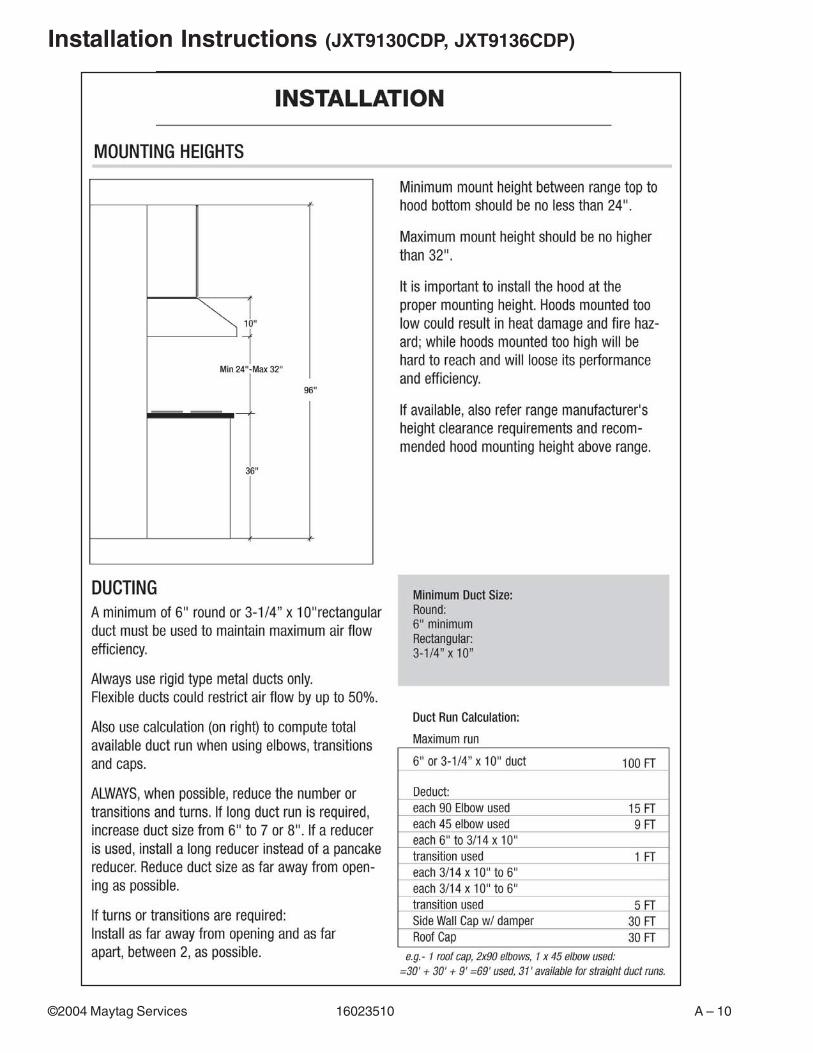
Installation Instructions (JXT9130CDP, JXT9136CDP)

A – 11 16023510 ©2004 Maytag Services
Installation Instructions (JXT9130CDP, JXT9136CDP)

©2004 Maytag Services 16023510 B – 1
Appendix B
B – 2 16023510 ©2004 Maytag Services
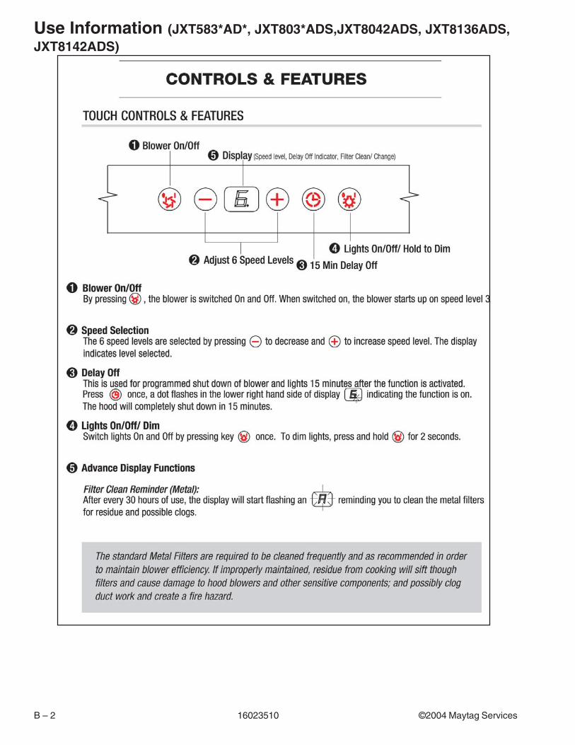
Use Information (JXT583*AD*, JXT803*ADS,JXT8042ADS, JXT8136ADS,JXT8142ADS)

©2004 Maytag Services 16023510 B – 3
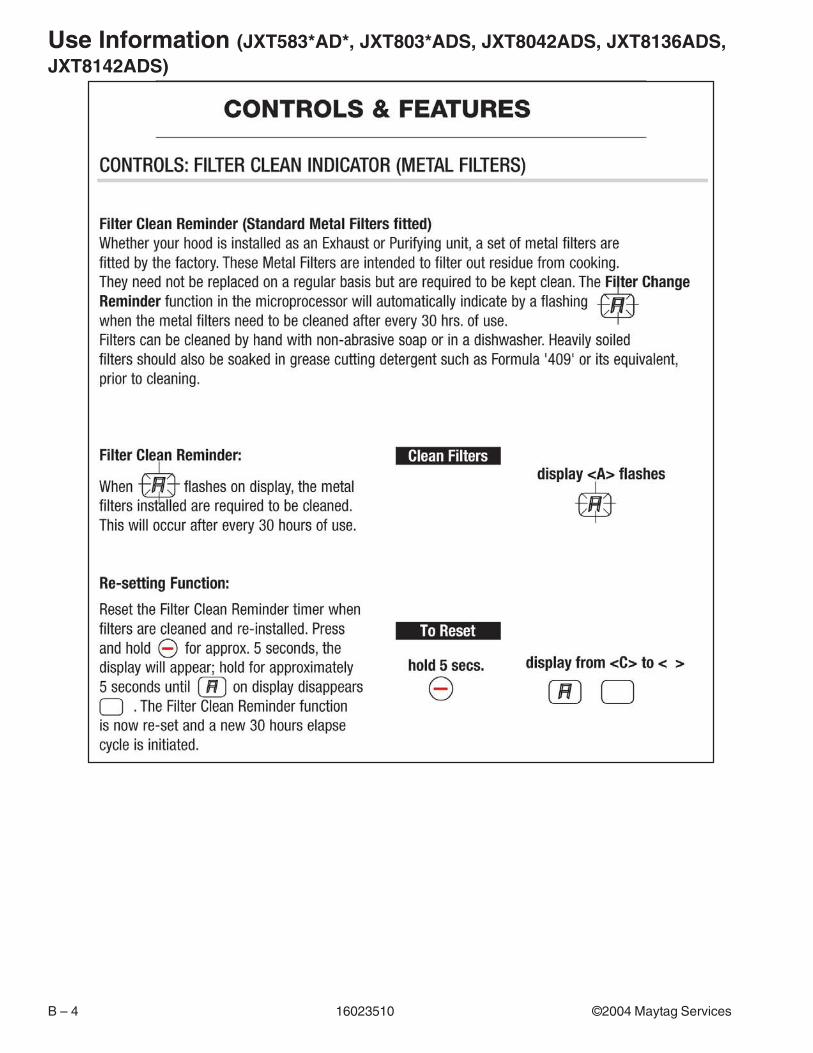
Use Information (JXT583*AD*, JXT803*ADS, JXT8042ADS, JXT8136ADS,JXT8142ADS)
B – 4 16023510 ©2004 Maytag Services
Use Information (JXT583*AD*, JXT803*ADS, JXT8042ADS, JXT8136ADS,JXT8142ADS)

©2004 Maytag Services 16023510 B – 5
Use Information (JXT903*CDP, JXT9048CDP, JXT913*CDP)

B – 6 16023510 ©2004 Maytag Services
Care and Cleaning (all)