built-in self test - auburn university
TRANSCRIPT

Smith Text: Chapter 14.7Mentor Graphics: LBISTArchitect Process Guide
Built-In Self Test

Top-down test design flow
Source: FlexTest Manual

Built-In Self-Test (BIST) Structured-test techniques for logic circuits to improve access to
internal signals from primary inputs/outputs BIST procedure: generate a test pattern apply the pattern to “circuit under test” (CUT) check the response repeat for each test pattern
Most BIST approaches use pseudo-random test vectors Most BIST approaches compress responses into a single “signature”

Logic BIST architecturePseudo-random
pattern generator
Multiple-inputsignature register
Source: Mentor Graphics “LBISTArchitect Process Guide”

Logic BIST general architecture
Source: Mentor Graphics “LBISTArchitect Process Guide”

Memory BIST architecture
Source: Mentor Graphics “MBISTArchitect Process Guide”

Linear Feedback Shift Register (LFSR) Produce pseudorandom binary sequences (PRBS) Implement with shift register and XOR gates Selection of feedback points allows n-bit register to produce a
PRBS of length 2n-1 LFSR produces pattern:111011001100010101110 (then repeats)(PRBS length 7)
Smith text figure 14.23

4-stage LFSR with one tap point
Source: Mentor Graphics “LBISTArchitect Process Guide”

Serial Input Signature Register (SISR) Use an LFSR to compact serial input data into an n-bit
“signature” Good circuit has a unique signature For sufficiently large n, two different sequences producing
the same signature is unlikely
Initialize LFSR to ‘000’ via RES.
Signature formed via shift & xor
Text figure 14.24

BIST Example (Fig. 14.25)
Circuit under test
Pattern generator Signature analyzer
Generatedtest
patterns
Outputsequences
Signatures
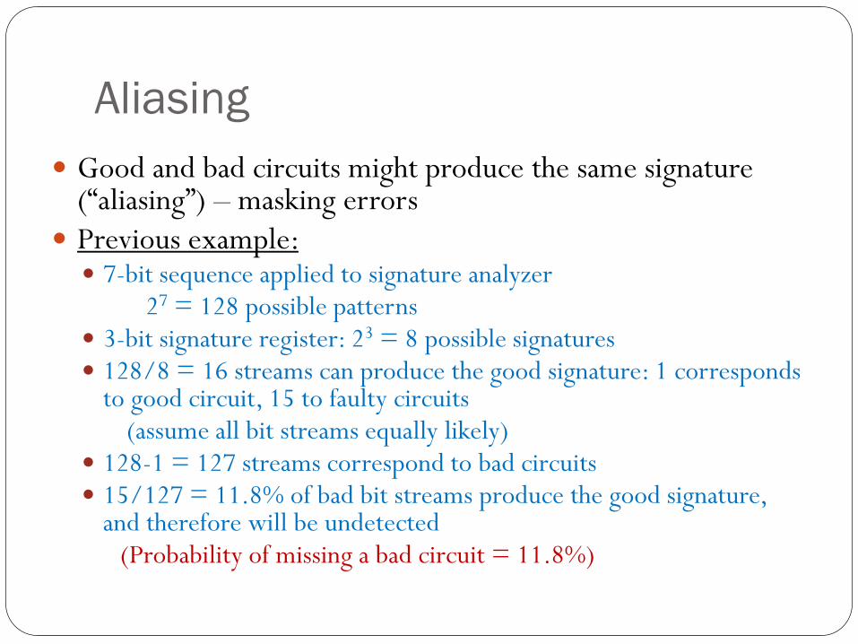
Aliasing Good and bad circuits might produce the same signature
(“aliasing”) – masking errors Previous example: 7-bit sequence applied to signature analyzer
27 = 128 possible patterns 3-bit signature register: 23 = 8 possible signatures 128/8 = 16 streams can produce the good signature: 1 corresponds
to good circuit, 15 to faulty circuits(assume all bit streams equally likely)
128-1 = 127 streams correspond to bad circuits 15/127 = 11.8% of bad bit streams produce the good signature,
and therefore will be undetected (Probability of missing a bad circuit = 11.8%)

Aliasing – Error ProbabilityGiven test sequence length L & signature register
length RProbability of aliasing is:
For L >> R:
Use long sequences to minimize aliasing:
1212
−−
=−
L
RLp
Rp −≈ 2
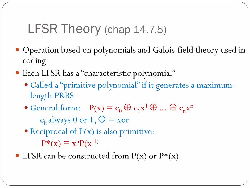
LFSR Theory (chap 14.7.5)
Operation based on polynomials and Galois-field theory used in coding
Each LFSR has a “characteristic polynomial”Called a “primitive polynomial” if it generates a maximum-
length PRBSGeneral form: P(x) = c0 ⊕ c1x1 ⊕ ... ⊕ cnxn
ck always 0 or 1, ⊕ = xorReciprocal of P(x) is also primitive:
P*(x) = xnP(x-1)
LFSR can be constructed from P(x) or P*(x)
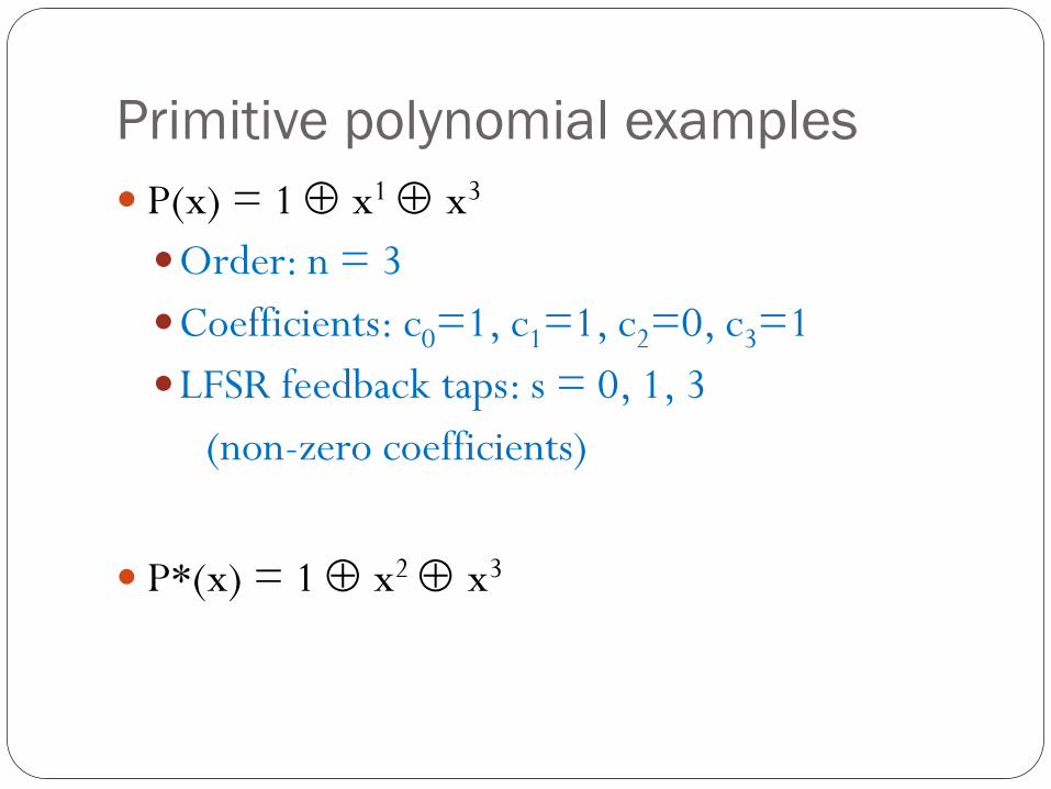
Primitive polynomial examples P(x) = 1 ⊕ x1 ⊕ x3
Order: n = 3Coefficients: c0=1, c1=1, c2=0, c3=1LFSR feedback taps: s = 0, 1, 3
(non-zero coefficients)
P*(x) = 1 ⊕ x2 ⊕ x3

“Type 1” LFSR schematic
If ck=1 add feedback connection & xor gate in position k

Four LFSR structures for every primitive polynomial
Type 1, P*(x) Type 1, P(x)
Type 2, P*(x)Type 2, P(x)
P(x) = 1 ⊕ x ⊕ x3 P*(x) = 1 ⊕ x2 ⊕ x3
Type 1-external XOR-easy to build fromexisting registers-Q outputs delayedby 1 clock(test seq’s arecorrelated)
Type 2-internal XOR-fewer series XORs
(faster)-outputs not correlated-usually used for BIST

Common LFSR Configurations
Source: Mentor Graphics “LBISTArchitect Process Guide”
Also see Figure 14.27 and Table 14.11 in the Smith Text

Multiple-Input Signature Register (MISR) Reduce test logic by using multiple bit streams to create a
signature BILBO (built-in logic block observer) – uses MISR as both
PRBS generator and signature register
Example: MISR from Type 2 LFSR with P*(x) = 1 ⊕ x2 ⊕ x3
omit xor_i3 if only 2 outputs to test

Mentor Graphics Tools LBISTArchitect logic BIST design & insertionReference: “LBISTArchitect Process Guide”
MBISTArchitectmemory BIST design & insertionReference: “MBISTArchitect Process Guide”

Architecture produced by LBISTarchitect
Source: Mentor Graphics “LBISTArchitect Process Guide”
generate patternsPRPG
collect & compactoutputs (MISR)

Logic BIST design flow
Source: Mentor Graphics “LBISTArchitect Process Guide”

Logic BIST insertion flow

Logic BIST design phases BIST-Ready: check design for testability insert scan circuits & test points
BIST Controller Generation: produce synthesizable RTL model (VHDL,Verilog) includes scan driver/PRPG, scan monitor/MISR
Boundary Scan Insertion (optional) BSDarchitect can tie 1149.1 to logic BIST inserts boundary scan ckts & TAP controller

LOGIC BIST design phases (2) Fault simulation & signature generation determine fault coverage of BIST patterns generate signature of “good circuit”
Sequential fault simulation (optional) determine fault coverage of BIST hardware
BIST verification (optional) generate test bench for full simulation
Manufacturing diagnostics (optional) generate info to assist in fault diagnosis

BIST-ready phase: test point insertion Add control test points to gain access to inputs of difficult-to-
test gates Add observe test points to gain access to outputs of difficult-
to-test gates MTPI: Multiphase Test Point Insertion break test into phases (ex. 256 patterns each) activate only test points used in a phase add points to improve detection of faults not detected in
previous test phases

MTPI Example