building information modeling: next steps for …...key words:tensile membrane architecture,...
TRANSCRIPT
93
VII International Conference on Textile Composites and Inflatable StructuresSTRUCTURAL MEMBRANES 2015
E. Oñate, K.-U.Bletzinger and B. Kröplin (Eds)
Building information modeling: next steps for tensile membrane architecture
VI International Conference on Textile Composites and Inflatable Structures STRUCTURAL MEMBRANES 2015
E. Oñate, K.-U.Bletzinger, and B. Kröplin (Eds)
BUILDING INFORMATION MODELING: NEXT STEPS FOR TENSILE MEMBRANE ARCHITECTURE
EVE S. LIN*AND ROBERT ROITHMAYR†
* Tensile Evolution North America3121 Michelson Dr., Suite 250, Irvine, CA 92612, USA
Email: [email protected]; Web page: http://www.tensileevolution.com/
† Tensile Evolution GmbH WienBeda Weber-Gasse 26, 9900 Lienz, Austria
Email: [email protected]; Web page: http://www.tensileevolution.com/
Key words: Tensile Membrane Architecture, Building Information Modeling, Design Technology, BIM maturity level, Design Integration.
Summary: With technological advancements in building design, increasing BIM maturity provides significant opportunities to improve the design process and performance of tensile membrane architecture. In order to isolate the next steps of technological development for tools specialized in tensile membrane design, this paper first conducts a case study to examine how BIM has been implemented successfully followed by a summary review of current tensile membrane tools and a detailed look at gaps to see where BIM maturity in tensile membrane architecture can improve.
1 INTRODUCTIONOver the last decade Building Information Modeling (BIM) has taken over as the new
computer aided design (CAD) paradigm in the industries of Architecture, Engineering, and Construction (AEC) for both professional and academic settings [45]. The ability to improve design quality [41], reduce construction costs [2], enhance facility management [48], and predict building performance [24] are recognized benefits make BIM the preferred form of project delivery. In addition, it is reported as an effective means to facilitate AEC education [38]. However, the aforementioned benefits of BIM are rarely realized in the field of tensile membrane architecture due to nonlinear behavior of tensile membrane architecture during the design process. Consequently, the current application of BIM in tensile membrane architecture is merely for geometric representation as part of project delivery. With technological advancement in the design industry and the maturity of form-finding, statistical analysis and patterning techniques, it is the time to focus on streamlining information from various sources during the design process, and thereby increase both the quality and usage of tensile membrane architecture.
To this end, this paper first reviews the technologies used for the London 2012 Olympic stadium to understand how it applied BIM, how BIM improved project delivery, and to identify shortcomings in the process. Next, the BIM maturity of currently available digital tools specific
1
94
Eve S. Lin and Robert Roithmayr
to tensile membrane architecture is measured against a generalized BIM maturity matrix. By comparing the capabilities of these tools, areas for improvement can be shown and the next steps toward closing the information feedback loop can be pursued more in depth. Thus, the results of this paper can serve as the basis for facilitating future design integration methods to improve design efficacy and advance the usage of tensile membrane architecture.
2 A BIM APPLICATION CASE OF TENSILE MEMBRANE ARCHITECTURE -LONDON 2012 OLYMPIC STADIUM
The London 2012 Olympic Stadium is one of the most revered tensile membrane projects that also been praised for its successful application of BIM technologies. Its tensile membrane roof design allowed it to be built using less than half the steel of comparable stadia, reducing its environmental impact and making it the lightest Olympic stadium constructed to date [7, 23]. The incorporation of 34% of recycled steel and concrete and other related environmentally conscious actions during the stadium design and construction make it the most environmentally friendly modern Olympic Stadium [7, 22]. Because of its application of BIM technologies, the project was completed one year early within a limited construction period of only 1,000 daysand under budget [39].
Despite all these record-breaking legacies set by the London 2012 Olympic Stadium, nosingle project to date has yet to fully realize all of BIM’s potential benefits. BIM’s potential benefits are yet to be discovered, identified or applied [18]. To this end, this case study focus on examining the application of BIM technologies and identifying the needs of future technological development to further facilitate the design of tensile membrane architecture.
2.1 Project BriefThe stadium was designed with the future in mind, incorporating inherent flexibility to be
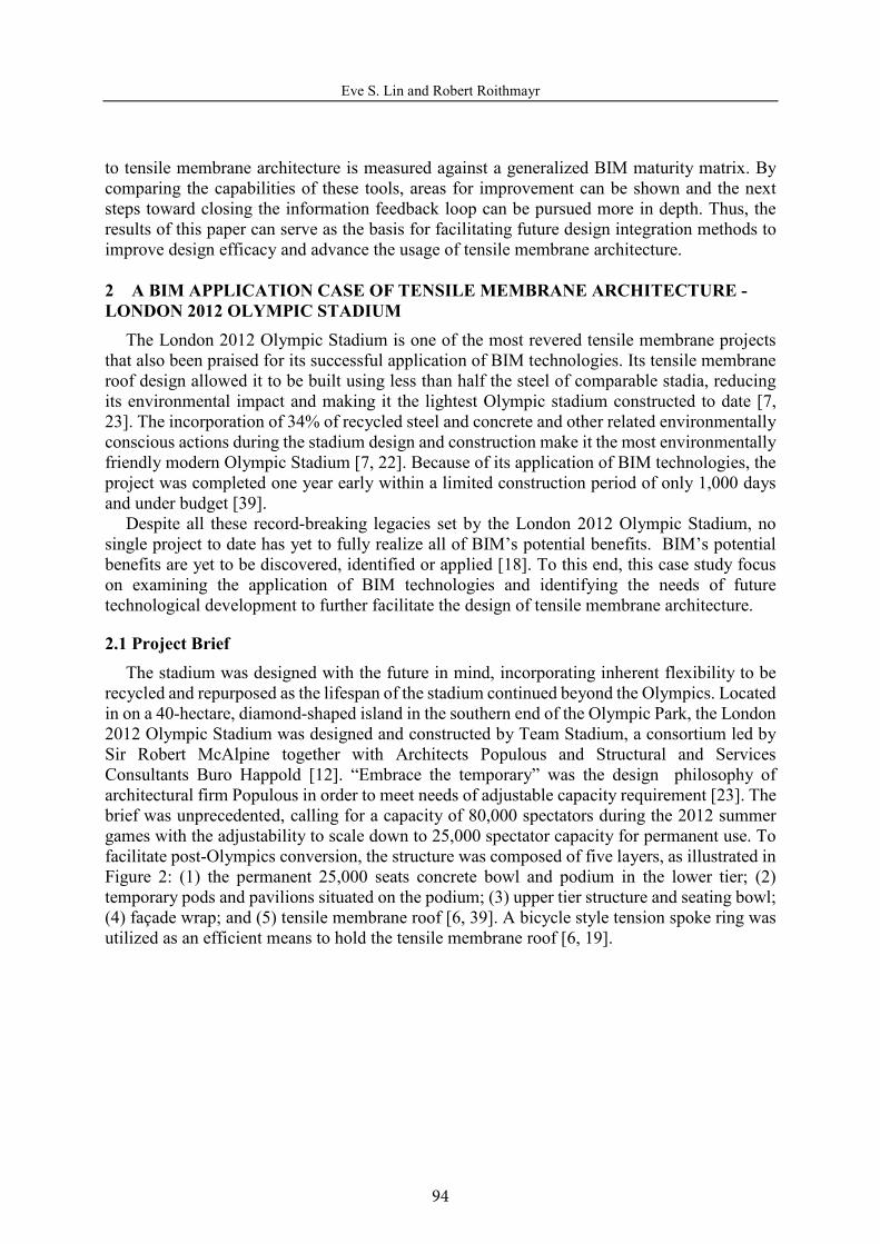
recycled and repurposed as the lifespan of the stadium continued beyond the Olympics. Located in on a 40-hectare, diamond-shaped island in the southern end of the Olympic Park, the London 2012 Olympic Stadium was designed and constructed by Team Stadium, a consortium led by Sir Robert McAlpine together with Architects Populous and Structural and Services Consultants Buro Happold [12]. “Embrace the temporary” was the design philosophy of architectural firm Populous in order to meet needs of adjustable capacity requirement [23]. The brief was unprecedented, calling for a capacity of 80,000 spectators during the 2012 summer games with the adjustability to scale down to 25,000 spectator capacity for permanent use. To facilitate post-Olympics conversion, the structure was composed of five layers, as illustrated in Figure 2: (1) the permanent 25,000 seats concrete bowl and podium in the lower tier; (2) temporary pods and pavilions situated on the podium; (3) upper tier structure and seating bowl; (4) façade wrap; and (5) tensile membrane roof [6, 39]. A bicycle style tension spoke ring was utilized as an efficient means to hold the tensile membrane roof [6, 19].
2
95
Eve S. Lin and Robert Roithmayr
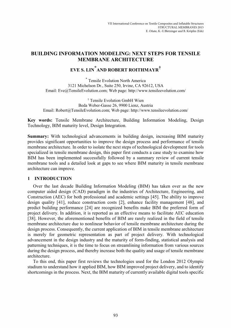
Figure 1: London 2012 Olympic Stadium general project information [39]. Photograph: Locog/EPA.
Figure 2: London 2012 Olympic Stadium exploded axonometric and west sections. Diagram: Populous.
2.2 BIM Applications of the London 2012 Olympic StadiumA fully integrated team along with an integrated BIM model was an essential reason that the
London Olympic Stadium was completed on budget and on time. The integrated construction management is the featured BIM capability of the London 2012 Olympic Stadium that led to this success. It allowed the model developed by the design team to be coordinated and visualized in an integrated form prior to construction. This helped the design team to clarifycomplex routing of services and troubleshoot potential issues prior to bringing in other sub-trades. Several different software were used among the design team, including Max, SolidWorks, Tekla, Revit, CADduct and MicroStation [9]. In order to generate an integrated model, Fulcro was appointed part of the design management team to coordinate the information from various expert domains [10].
While there was a lot of praise for the success of using integrated model for construction management, the integration process was not as streamlined as what would be considered ideal. The integrated model required BIM experts to first collect different design team’s “final” design
Client: ODA, Olympic Delivery AuthorityArchitect: PopulousStructural and services engineers: Buro HappoldMain contractors: Sir Robert Mc Alpine
Construction period: May 2008 - March 2011Opening: 5 May 2012Cost: £ 498 millionSeats: 25,000 permanent and 55,000 temporary
Dimensions: 310 x 260 mStadium height: 62.7 m Pre-cast units in stadium bowl: 8,000Reinforced pre-cast concrete within stadium bowl: 9,250 m³Roof area: 24,500 m² Length of cable in roof: 6,000 m Weight of steel construction: 10,000 tEntrances: 56Rooms: 700
TENSILE MEMBRANE ROOF
FAÇADE WRAP
UPPER TIER STRUCTURE
PODS AND PAVILIONS
LOWER BOWL & PODIM
EXPLODED AXONOMETRIC WEST SECTION
3
96
Eve S. Lin and Robert Roithmayr
models across different design platforms, then it had to manually rebuild them or utilizestandardized file exchange formats to transfer model information (depending on each platform’s interoperability) into a single unified and integrated mode for collaboration purpose[9]. This made it difficult to make design changes or minor adjustments. While the integrated model was helpful for resolving conflicts among different trades, any modification made to the design required a manual update by individual trades. Furthermore, there was no connection between the integrated model and design analysis data, making it difficult to draw performance conclusions from the designing process.
Aside from construction management technologies, other advanced technologies were utilized for this project. Computer-aided flow simulation models were conducted to determine the coverage of the seating for optimal wind flow conditions [39]. Dynamic structural performance evaluations were conducted for seating tiers [11]. Intensive point cloud laser scanning was used to ensure precision installation during construction [3]. However, these data were still segmented for each design phase, and did not help build a cohesive design space. The design of tensile membrane roof demonstrated this disconnection within the process. Along with recently released information elaboration from the structural engineer [6], studying how the membrane roof was created presents the technological issues that were encountered during process:
1. Determination of suitable form-finding algorithms and software packages: The essential capability for any tensile membrane software package is its ability to model and analyze non-linear geometric membrane behavior to find the form and facilitate the subsequent load analysis. However, there is still a lack of conformable approach to ensure the accuracy of the algorithm. For this reason, the structural analyses were used at least two software packages for cross-checking purpose. This led to uncertainty during the design process.
2. Consideration of materials’ non-linear properties: OASYS GSA was used as the structural analysis tool for the tensile membrane roof including all the components of structural steelwork, cables and fabric membrane in the roof structure. However, similar to other solvers, it only considers linear elasticity and is not sufficient to consider the full material property of the membrane. The effects of the material properties for the overall performance of a large fabric membrane structure are significant and should therefore include complete data for proper analysis and design. A structural solver that considers complete material properties beyond linear elasticity is needed.
3. Reliability and resilience in the membrane design: There was a lack of sufficient guidance and safety factors available for the tensile membrane façade industry to ensure the reliability of the analysis. Only general guidance was available through Tensinet, but even this was heavily tailored for use in Germany. The assessment and calculation of appropriate reliability indices for tensile membrane architecture are needed.
4. Multiple models were needed for deferent levels of analysis: During the design analysis process, various models in different scales were used, including a complete stadium model for primary structural analysis, a quarter stadium model to assess the fabric membrane behavior, and a detailed signal-bay model to assess the penetration’s effects within the surface. This repetitive process of modeling is slow and allows room for an increased probability of human error.
4
97
Eve S. Lin and Robert Roithmayr
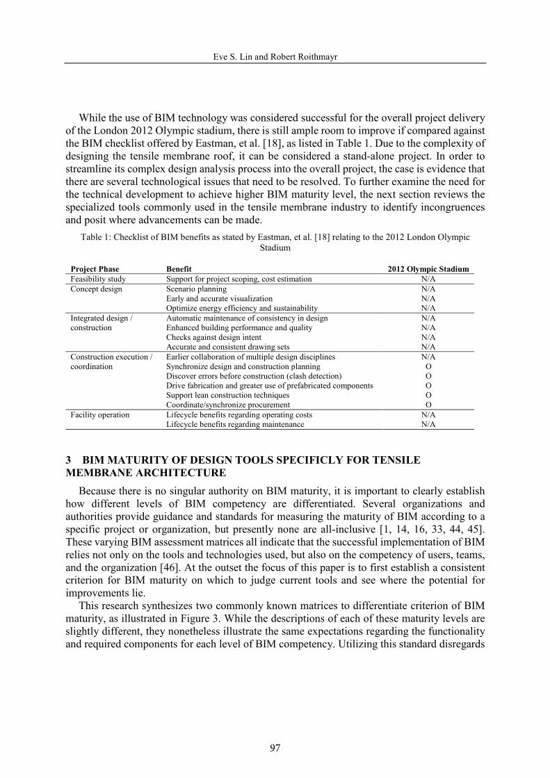
While the use of BIM technology was considered successful for the overall project deliveryof the London 2012 Olympic stadium, there is still ample room to improve if compared against the BIM checklist offered by Eastman, et al. [18], as listed in Table 1. Due to the complexity of designing the tensile membrane roof, it can be considered a stand-alone project. In order to streamline its complex design analysis process into the overall project, the case is evidence that there are several technological issues that need to be resolved. To further examine the need for the technical development to achieve higher BIM maturity level, the next section reviews the specialized tools commonly used in the tensile membrane industry to identify incongruencesand posit where advancements can be made.
Table 1: Checklist of BIM benefits as stated by Eastman, et al. [18] relating to the 2012 London Olympic Stadium
Project Phase Benefit 2012 Olympic StadiumFeasibility study Support for project scoping, cost estimation N/AConcept design Scenario planning N/A
Early and accurate visualization N/AOptimize energy efficiency and sustainability N/A
Integrated design / construction
Automatic maintenance of consistency in design N/AEnhanced building performance and quality N/AChecks against design intent N/AAccurate and consistent drawing sets N/A
Construction execution / coordination
Earlier collaboration of multiple design disciplines N/ASynchronize design and construction planning ODiscover errors before construction (clash detection) ODrive fabrication and greater use of prefabricated components OSupport lean construction techniques OCoordinate/synchronize procurement O
Facility operation Lifecycle benefits regarding operating costs N/ALifecycle benefits regarding maintenance N/A
3 BIM MATURITY OF DESIGN TOOLS SPECIFICLY FOR TENSILE MEMBRANE ARCHITECTURE
Because there is no singular authority on BIM maturity, it is important to clearly establish how different levels of BIM competency are differentiated. Several organizations and authorities provide guidance and standards for measuring the maturity of BIM according to a specific project or organization, but presently none are all-inclusive [1, 14, 16, 33, 44, 45].These varying BIM assessment matrices all indicate that the successful implementation of BIM relies not only on the tools and technologies used, but also on the competency of users, teams, and the organization [46]. At the outset the focus of this paper is to first establish a consistent criterion for BIM maturity on which to judge current tools and see where the potential for improvements lie.
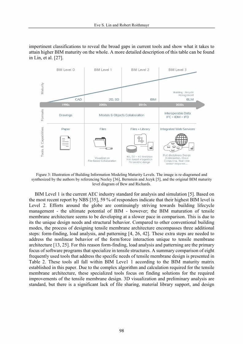
This research synthesizes two commonly known matrices to differentiate criterion of BIMmaturity, as illustrated in Figure 3. While the descriptions of each of these maturity levels are slightly different, they nonetheless illustrate the same expectations regarding the functionality and required components for each level of BIM competency. Utilizing this standard disregards
5
98
Eve S. Lin and Robert Roithmayr
impertinent classifications to reveal the broad gaps in current tools and show what it takes to attain higher BIM maturity on the whole. A more detailed description of this table can be found in Lin, et al. [27].
Figure 3: Illustration of Building Information Modeling Maturity Levels. The image is re-diagramed and synthesized by the authors by referencing Neeley [36], Bernstein and Jezyk [5], and the original BIM maturity
level diagram of Bew and Richards.
BIM Level 1 is the current AEC industry standard for analysis and simulation [5]. Based on the most recent report by NBS [35], 59 % of responders indicate that their highest BIM level is Level 2. Efforts around the globe are continuingly striving towards building lifecycle management - the ultimate potential of BIM - however; the BIM maturation of tensile membrane architecture seems to be developing at a slower pace in comparison. This is due to its the unique design needs and structural behavior. Compared to other conventional building modes, the process of designing tensile membrane architecture encompasses three additional steps: form-finding, load analysis, and patterning [4, 26, 42]. These extra steps are needed to address the nonlinear behavior of the form/force interaction unique to tensile membrane architecture [13, 25]. For this reason form-finding, load analysis and patterning are the primary focus of software programs that specialize in tensile structures. A summary comparison of eight frequently used tools that address the specific needs of tensile membrane design is presented inTable 2. These tools all fall within BIM Leve1 1 according to the BIM maturity matrix established in this paper. Due to the complex algorithm and calculation required for the tensile membrane architecture, these specialized tools focus on finding solutions for the required improvements of the tensile membrane design. 3D visualization and preliminary analysis arestandard, but there is a significant lack of file sharing, material library support, and design
6
99
Eve S. Lin and Robert Roithmayr
collaboration required to raise maturity to BIM Level 2 and beyond. Table 2: A comparison of eight common software tools specialized for tensile membrane architecture
Too
ls
Form
-fin
ding
Forc
e / S
tres
s C
onsi
dera
tion
FEA
/ FE
M
Cut
ting
Patt
ern
Des
ign
Inte
grat
ion
Tar
get U
ser
Oth
er fe
atur
es
Easy [47] DXF/DWGFormfinder, RSTAB Engineer Pneumatic structure
Formfinder [20] DXF/DWGRhino Plugin, Easy Architect
ixCube 4-10 [17] Rhino/AutoCADCaedium Fluid Solver Engineer
CFD, Scripting, material database, Code Compliance steel design
MPanel [31] Rhino/AutoCAD Not Specified
NDN [8] DXF/DWG Engineer
Oasys GSA [37]
ADC AdBeam, ASAS, DXF/DWG, CIMsteel, LS-DYNA, NASTRAN, OpenSees Revit Structure, SAP2000, Steel Member CSV, Vdisp
Engineer Complete structural system design.
Patterner [40] MEM, DXF/DWG/WRL Not Specified
TensileDraw [30] Rhino/AutoCAD Plug-in Not specified
4 POTENTIAL DEVELOPMENT & NEXT STEPSVarious improvements can still be made to improve calculation accuracy and assist design
and analysis of a tensile membrane structure. It is time to examine how to integrate and streamline the design process and information sharing within various tensile membrane design stages. The means and methods to integrate the design of tensile membrane architecture with other project-wide design activities must be sought to further embrace the great potential in lean construction and higher environmental and lifecycle performance. The following provides some directives to increase BIM maturity for these tools.1. User-friendliness: Software usability relies on the design of the user interface and how it
facilitates user interaction within the working environment. Current tools for tensile membrane design tend to be engineering-oriented, making concept generation and manipulation difficult for those who lack an engineering background. Ultimately, an effective tool should be able to provide design guidance while ensuring the constructability of the design without limiting creativity during the process.
2. Interoperability: Current tools for tensile membrane design focus solely on solving the needsspecific to tensile membrane architecture. Material properties and analytical attributes are only stored within each standalone application, and are not transferable to other design
7
100
Eve S. Lin and Robert Roithmayr
platforms or BIM authoring tools. This limits interoperability between design suites togeometric representations solely for design documentation. This is a major barrier to increasing BIM potential. It is currently possible to utilize third party platforms for projectcollaboration, however; these collaboration platforms only support post-analyzed geometric components. Therefore an IFC standardized format is imperative to advancing BIM maturity. While the technology for exchanging information using IFC has been established, the application for tensile membrane architecture still requires additional development before a comprehensive solution can be practically applied. Exchanging geometry and materials information between analytic tools still requires further development [34].
3. Database: Although all specialized tensile membrane software claims intelligent form-finding capabilities, there is a huge lack for component attribute information. As mentioned in the London Olympics case study, the accuracy of analysis is highly dependent on material properties. This is not fully supported by presently available tools. Currently, geometries can only be exported for 3D representation without associated attributes such as material properties, or stress level tolerance. These material attributes are not associated with the resulting geometric model and therefore cannot be transferred, used, or stored in other platforms for further documentation or simulation. Once the geometry loses its component’s attributes, the model loses its intelligence and can only be used for 3D representation. In order to enable cost estimation, lifecycle analysis, or other environmental analysis throughout a building’s lifecycle, the materials and structural objects need to be associated with data-rich attributes.
4. Construction Management, 4D, 5D to nD Simulations: The benefits of current BIM technology are its ability to conduct construction simulation, clash detection, cost estimation and logistics planning. The previously presented case study is one such example of success in utilizing BIM for clash detection, however; it was done by manually integrating multiple models. While this method is effective, manually reentering each model to enable various simulations increases time and resources and needs further analysis of its cost effectiveness and margin of error. Currently, none of the tools reviewed facilitate direct exporting and integration without remodeling or modification. To conduct these in-depth simulations isespecially important for tensile membrane architecture since many reported failures occur during the delivery and installation process [32]. The assembly process, too, is an essentialstep to be considered during the detailing stage to ensure the quality and durability of the corner details, and thus the overall structure [21]. The availability of these integrated features can be expected to increase the quality of the overall design and lead to better construction and cost management of tensile membrane projects. The concept can also be applied to simulating sustainability and life cycle performance (6D), as well as for a building’s operation and facility management (7D). But, to be able to achieve these capabilities, the intelligently integrated data-rich model is a fundamental requirement and needs to be established first.
Streamlining the design analysis process is a major challenge not only for tensile membrane architecture but for all types of building design. Closing the performance feedback loop between design and various analytic domains has been an important topic among AEC research and practice [28]. It is even more challenging for tensile membrane architecture to close the
8

101
Eve S. Lin and Robert Roithmayr
feedback loop given its complex geometry and unique material properties [15]. Since pursuing sustainability and a high performing built environment has become imperative, the ability to access these performance assessments (i.e. structural, thermal, acoustical, and energy performance) early in the design process is critical to optimizing structural design from the outset. In order to achieve this, the previously mentioned interoperability and knowledge-based library needs to be established first. The material library, too, must be enriched with the inclusion of physical properties for design analysis. Furthermore, the ability to effectively simulate and evaluate the performance of these dramatically complex forms must be sought out. When design analysis becomes streamlined, it is then possible to utilize parameterization, platform integration, and multi-objective optimization algorithms with cloud computing functionality to quickly generate design solutions and identify the best compromise given the design objectives [29]. In addition to raising environmental performance, streamlining design analysis is vital to advancing specific critical elements, such as corner detailing. Analyzing the relationship between shape, performance and materials in the makeup of the corner assembly is crucial because the long-term performance of the corner detail determines the integrity of the entire structure. Addressing these issues remains the most significant challenge specific to tensile membrane architecture [43].
5 CONCLUSIONThis paper seeks to establish the efficacy and current state of BIM in tensile membrane
architecture. A recent project in the London 2012 Olympic Stadium is a representative case study that shows the benefits of BIM, but also reveals areas for improvement. This is followedby an in-depth look at the capabilities of current design tools and a discussion of steps that need to be taken to increase BIM maturity. Within this discussion this paper establishes a general BIM maturity matrix synthesized from common accepted matrices to signify the current maturity and describe what constitutes BIM maturity in the future. It is revealed that the development of the tensile membrane tools are not yet satisfactory and are behind compared to conventional building modalities. This is due to the specific needs of tensile membrane architecture. The geometries, forms and components in the tensile membrane design must be configured simultaneously and be subjected to specific pattern of internal forces analysis. These distinctive needs can potentially be explored by enabling higher BIM maturity. Increasing the BIM maturity of specialized tensile membrane tools can make the evaluation of structural functions and composite forms an easier and far more productive process. It is imperative to establish a standardized data model to enable interoperability, associative material attributes,and integration with other design analysis platforms and complete the feedback loop.
The potential for tensile membrane architecture to cultivate a higher performing built environment is promising. The lightweight, translucent, and flexible nature of tensile membrane architecture has vast implications for improving building performance. As an emerging design medium, it enables a wide range of dynamically unique forms for heightened design creativity. By continuingly striving to elevate BIM maturity, tensile membrane architecture will be more accessible to design professionals and contribute to a more dynamic, higher performing built environment.
9
102
Eve S. Lin and Robert Roithmayr
REFERENCES[1] Arup. Building Information Modelling (BIM). 2014. Available:
http://www.arup.com/Services/Building_Modelling.aspx.[2] S. Azhar, Building information modeling (BIM): Trends, benefits, risks and challenges for
the AEC industry. Leadership and Management in Engineering. 2011, 11:241-252.[3] A. Barrow, Scanning London's Olympic Stadium. Professional Surveyor Magazine.
Flatdog Media, Inc., 2012.[4] P. Beccarelli, The design, analysis and construction of tensile fabric structures. in Biaxial
Testing for Fabrics and Foils: Optimizing Devices and Procedures. Berlin: Springer, 2015, 9-34.
[5] P.G. Bernstein and M. Jezyk, Model and measurement: Changing design value with simulation, analysis, and outcomes. in Building Information Modeling : BIM in Current and Future Practice, K. Kensek and D. Noble (eds.). Somerset, NJ, USA: Wiley, 2014, 79-94.
[6] M. Birchall, 22 - Recent developments in architectural fabric structures in Europe: The design and construction of the London 2012 Olympic Stadium and its context in the European fabric structures market. in Fabric Structures in Architecture, J.I.d. Llorens (ed.).Woodhead Publishing, 2015, 773-817.
[7] G. Bizey. Steel structure of the London 2012 Olympic stadium. Building Design, 2011. Available: http://www.bdonline.co.uk/steel-structure-of-the-london-2012-olympic-stadium/5016252.article.
[8] M.L. Brown. Membrane NDN Software. 2015. Available: http://www.ndnsoftware.com/.[9] BuildingSMART UK, BIM for the public sector, Olympic Stadium benefits from BIM, the
new BIM Acadamy, Classification tables and BIM, UN/CEFACT e-invoicing and the database of compliant IFC software. BuildingSMART News. 2011. Available: http://www.buildingsmart.org.uk/newsletter/2011-newsletters/buildingsmart-news-27-2011-11/view.
[10]BuildingSMART UK, Public sector demand for BIM. London 2012 Olympic dreams and realities. Singapore supports BIM. buildingSMART collaboration with ISO. BuildingSmart International Newsletter. 2011. Available: http://www.buildingsmart.org.uk/newsletter/2011-newsletters/buildingsmart-international-newsletter-06-2011-11/view.
[11]BuroHappold Engineering, BuroHappold on Stadia Design. 2015.[12]BuroHappold Engineering. London 2012 Olympic Stadium. 2015. Available:
http://www.burohappold.com/projects/project/london-2012-olympic-stadium-132/.[13]D.M. Campbell, The unique role of computing in the design and construction of tensile
membrane structures, in ASCE Second Civil Engineering Automation Conference.Proceedings of ASCE Second Civil Engineering Automation Conference, New York, 1991.
[14]ChangeAgents AEC Pty Ltd. BIMe. 2015.[15]S.K. Chiu and E.S. Lin, Transformable tensile façade: Performance: assessment on energy,
solar and daylighting, in Advanced Building Skins 2015. Advanced Building Skins 2015 Conference Proceedings, O. Englhartdt, ed., Graz University of Technology, 2015.
10
103
Eve S. Lin and Robert Roithmayr
[16]Computer Integrated Construction Research Program. BIM Planning Guide for Facility Owners, University Park, PA, USA, The Pennsylvania State University, 2013.
[17]G. D'Anza. ixCube 4-10®. IxRay ltd., 2014. Available: http://www.ixray-ltd.com/index.php?option=com_content&view=article&id=87&Itemid=520.
[18]C. Eastman, P. Teicholz, R. Sacks and K. Liston. BIM Handbook: A Guide to Building Information Modeling for Owners, Managers, Designers, Engineers and Contractors,Wiley, 2011.
[19]T. Forbes. Working on the London Olympic Stadium. UK Contractors Group Ltd., 2014. Available: http://www.borntobuild.org.uk/news/2014/sep/16/working-on-the-london-olympic-stadium/.
[20]Formfinder Software GmbH Formfinder. 2014. Available: http://www.formfinder.at/.[21]B. Forster, Design of the details. in Membrane Structures: Innovative Building with Film
and Fabric, K.-M. Koch (ed.). Munich, Berlin, London, New York: Prestel Verlag, 2004, 124-137.
[22]International Olympic Committee, Factsheet - London 2012 facts & figures. 2013. Available: http://www.olympic.org/Documents/Reference_documents_Factsheets/London_2012_Facts_and_Figures-eng.pdf.
[23]G. John, R. Sheard and B. Vickery. Stadia: The Populous Design and Development Guide, Abingdon, Oxon; New York, Routledge, 2013.
[24]E. Krygiel, B. Nies, E. Krygiel and B. Nies. Green BIM: successful sustainable design with building information modeling, Indianapolis, Ind., Wiley Pub., 2008.
[25]W.J. Lewis, Modeling of Fabric Structures and Associated Design Issues. Journal of Architectural Engineering. 2013, 19(2):81-88.
[26]W.J. Lewis. Tension Structures: Form and Behaviour, London : Reston, VA, Thomas Telford Publishing, 2003.
[27]E.S. Lin, R. Roithmayr and S.K. Chiu, A review of BIM maturity for tensile membrane architecture, in IASS 2015: Future Vision. Proceedings of the International Association for Shell and Spatial Structures (IASS) Symposium 2015, Amsterdam, The Netherlands, 2015.
[28]S.-H. Lin and D.J. Gerber, Evolutionary Energy Performance Feedback for Design: Multidisciplinary Design Optimization and Performance Boundaries for Design Decision Support. Energy and Buildings. 2014, 84:426-441.
[29]S.-H.E. Lin and D.J. Gerber, Designing-in performance: A framework for evolutionary energy performance feedback in early stage design. Automation in Construction. 2014,38:59-73.
[30]ME+C S.r.l. TensileDraw: the Tensile Structure Software. 2015. Available: http://www.me-c.it/index.php/tss/wathis.
[31]Meliar Design. MPanel Software. 2015. Available: http://www.meliar.com/MPanel.htm.[32]J. Monjo-Carrió, 13 - Understanding and overcoming failures associated with architectural
fabric structures. in Fabric Structures in Architecture, J.I.d. Llorens (ed.). Woodhead Publishing, 2015, 417-445.
[33]National Institute of Building Sciences, National BIM Standard - United States™. Washington, DC, 2012.
11
104
Eve S. Lin and Robert Roithmayr
[34]N.O. Nawari, BIM standard: Tensile structures data modeling, in 2014 International Conference on Computing in Civil and Building Engineering. Proceedings of the International Conference on Computing in Civil and Building Engineering 2014, R.R. Issa and I. Flood, eds., Orlando, Florida, USA, 2014, 1166-1173.
[35]NBS, NBS National BIM Report 2015. Royal Institute of British Architects, 2015.[36]D. Neeley, BIM 1.0, BIM 2.0, BIM 3.0 - 2010 Update, in 2010 AIA National Convention.
Miami, 2010.[37]Oasys. GSA Suite. 2015. Available: http://www.oasys-
software.com/products/engineering/gsa-suite.html.[38]F. Peterson, T. Hartmann, R. Fruchter and M. Fischer, Teaching construction project
management with BIM support: Experience and lessons learned. Automation in Construction. 2011, 20(2):115-125.
[39]V.P. Popp and E. Margaretha, London 2012 - Olympic Stadium. Detail Das Architekturportal. 2012.
[40]B. Postle and R. Enos. Patterner 4.0.5 download site. 2015. Available: http://www.patterner.co.uk/.
[41]R. Sacks and R. Barak, Impact of three-dimensional parametric modeling of buildings on productivity in structural engineering practice. Automation in Construction. 2008,17(4):439-449.
[42]J. Sánchez, M.Á. Serna and P. Morer, A multi-step force–density method and surface-fitting approach for the preliminary shape design of tensile structures. Engineering Structures. 2007, 29(8):1966-1976.
[43]W. Sobek, Applied Methods and Perspectives of Tensile Membrane Architecture and Corner Detailing. In: E.S. Lin, S.K. Chiu and R. Roithmayr (eds.). Irvine, California: Tensile Evolution North America, Inc., 2015.
[44]Strategic Building Innovation. bimSCORE. 2015. Available: https://www.sbi.international/index.php/welcome.
[45]B. Succar, Building information modelling framework: A research and delivery foundation for industry stakeholders. Automation in Construction. 2009, 18(3):357-375.
[46]B. Succar, Building information modelling maturity matrix. in Handbook of Research on Building Information Modeling and Construction Informatics: Concepts and Technologies,J. Underwood and U. Isikdag (eds.). Information Science Publishing, 2009, 65-103.
[47]technet GmbH. Easy - Software for the integrated planning and calculation of lightweight surface structures. 2015. Available: http://www.technet-gmbh.com/index.php?id=63&L=1.
[48]P.M. Teicholz (ed.) BIM for Facility Managers, Hoboken, N.J.: John Wiley & Sons, 2013.
12