bose panaray ma12 modular array: technical … systems division bose corporation, framingham, ma,...
TRANSCRIPT
Professional Systems DivisionBose Corporation, Framingham, MA, USA
April 2002
Bose® P a n a r a y MA12 Modular Array:Technical Foundation & Discussion
Morten JørgensenManager, Marketing and Product Planning
Kenneth JacobChief Engineer

Bose® MA12™ Modular Array: Technical Foundation & DiscussionApril 2002, © Bose Corporation, All Rights Reserved
Page 2 of 36
[Insert blank page here]
Bose® MA12™ Modular Array: Technical Foundation & DiscussionApril 2002, © Bose Corporation, All Rights Reserved
Page 3 of 36
Bose® MA12 Modular Array:Technical Foundation & Discussion
Morten Jørgensen and Kenneth Jacob, Bose® Professional Systems Division
Summary
THE Bose MA12™ modular array takes advantage of the properties of cylindricalwaves to meet customer requirements that until now could only be met withloudspeakers flown and aimed in more elaborate and expensive designs. With onlytwo dimensions of dispersion rather than the three of the more common sphericalwaves, the sound from cylindrical waves diminishes much more gradually withdistance from the source. As a consequence, listeners experience relatively littlechange in sound level from far away from the MA12 to literally right next to it. Thesame gradual change in sound with distance makes the MA12 less susceptible tofeedback from microphones in close proximity. The radiation pattern of the MA12 iswedge-shaped: wide from side-to-side but sharply confined to the top and bottom ofthe array. The vertical radiation virtually shuts off above and below the speaker. As aresult, much less reverberation is generated because almost no sound is radiatedupwards to distant surfaces in the upper part of the room. The result is noticeablybetter clarity and intelligibility. The ultra-thin shape of the MA12 means it is easy tohide; it may be the most unobtrusive speaker yet developed given its exceptionallyhigh output and full, balanced frequency response. The fact that the MA12 is placedat ear level (so that listeners are confined within its wedge-shaped radiation pattern)means that it can usually be installed for a fraction of the cost of more elaborate‘flown’ loudspeakers and loudspeaker clusters. Finally, it can be matched to a lowfrequency enclosure (Bose Panaray MB4) when extended bass performance isneeded. Taken together, these features and advantages result in a product thatrepresents an important new tool for satisfying the most basic and important customerrequirements in a wide range of common applications.
Bose® MA12™ Modular Array: Technical Foundation & DiscussionApril 2002, © Bose Corporation, All Rights Reserved
Page 4 of 36
INTRODUCTION
CUSTOMER requirements for a sound system are diverse and cover the areas of acoustics,architecture, operation and service. Some of the most important requirements include thefollowing:
- Customers value a system that has the right balance of low, mid and high frequencies –what is called ‘tonal balance’. Customers hear and complain about sound that is too‘boomy’ or ‘shrill’ or ‘sibilant’, all examples of tonal balance problems.
- A system that plays at the right level is better than one that is too soft or too loud.Customers routinely complain about both excessive sound levels or when the desiredimpact can not be achieved because the system is unable to play loud enough.
- A system where the sound is perceived to come from the same direction as the action towhich it corresponds is better in many applications. When, for example, a talker is onstage, a system whose sound is perceived to come from the stage is better than onewhere the sound comes from above. Lack of eye-ear correspondence is disconcertingand distracting.
- A system that delivers music with clarity, and speech with intelligibility, is better thanone where instruments are garbled and speech is hard to understand. No other singlecustomer requirement generates as many complaints as poor speech intelligibility. Itoften impacts the fundamental purpose of a venue – the sermon or lecture at a house ofworship, or the announcement at the airport, for example.
- Customers are understandably concerned about the appearance of a sound system. Theyusually value a system that blends into its environment, and is out of the way. Andwhen the system is visible, customers want it to be elegant yet unobtrusive.
- Finally, customers value a system that works reliably for long periods of time withoutdegradation or the need for service. But should a problem occur, they want prompt,cost-effective service. No customer wants to shut down a facility in order to undertakerepairs.
These customer requirements exist on any given project to one degree or another. Forexample, in a place of worship a customer might seek nearly ideal speech intelligibility. Butin another situation, the required speech intelligibility might be set lower – to meet agovernment standard for an emergency announcement in a shopping mall, for example.Therefore, the intensity of need in each dimension on a specific project must be determinedfor each project.
Customer satisfaction occurs to the degree that the performance levels in these key areas ofcustomer requirements are met at a competitive cost. The better system is always the one thatmeets customer requirements for the least cost.
The standard design approach for meeting these requirements is unofficially called the‘hang-and-tilt’ approach. In this approach, speakers with controlled radiation patterns are
Bose® MA12™ Modular Array: Technical Foundation & DiscussionApril 2002, © Bose Corporation, All Rights Reserved
Page 5 of 36
hung in the air and tilted down. Hang-and-tilt has become the de facto standard for soundreinforcement in virtually every kind of venue, from retail spaces, to atriums, churches,schools, gymnasiums, auditoriums, city halls, airports, and sports facilities.
Manufacturers including Bose offer a wide range of speakers used in the hang-and-tiltapproach, and similarly, offer a wide range of tools to help the designer of these systems. Asa result, dealers, contractors, consulting engineers, and others have learned to deliver systemsthat perform well in satisfying the major customer requirements using this approach.
The purpose of this paper is to show that the Bose MA12™ modular array represents asignificant and important extension to the hang-and-tilt approach. To do this, our strategyrelies on an explanation of the speaker’s unique sound radiation pattern, and how thatradiation pattern, and the thin line-shaped source necessary to produce it, often allowsdesigners to meet customer requirements better and at a lower cost than before. The argumentbegins with a review of the fundamental assumption that first led the industry to the hang-and-tilt approach and then moves on to explain the approach’s strengths and remainingweaknesses.
THE HANG-AND-TILT APPROACH
Original assumption
WHAT led the industry to embrace the hang-and-tilt method and dedicate decades of research,development and marketing effort to perfect it? Why do so many speakers end up in the airand tilted down?
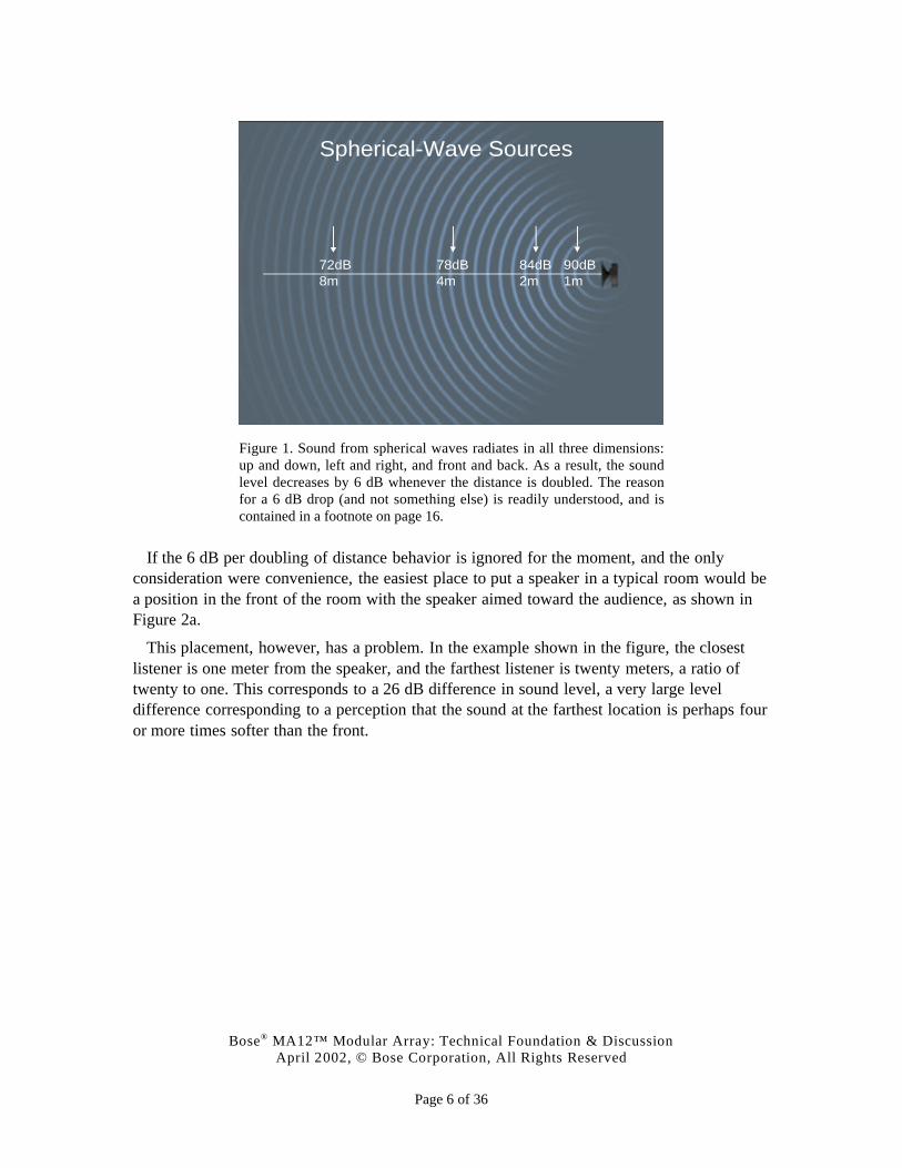
The answer can be traced to a fundamental property of the speakers used – specifically,that the sound waves they radiate spread in all three dimensions: up and down, left and right,in and out. These are called spherical waves because the sound radiates in all directions, likea sphere. As a result, the sound intensity, or sound pressure level from spherical wave sourcesdecreases by 6 dB whenever the distance is doubled, as shown in Figure 1. (To be exact, thisis true beyond a certain distance from the speaker. At very close distances the behavior isdifferent.)
For example, if a listener is four meters from the speaker and the level is 78 dB-SPL, thenwhen the listener is eight meters away – twice the distance – the level is 6 dB less, or 72 dB-SPL. And while a speaker often has different intensity levels at different angles (as is the casewith any directional speaker), no matter what angle is chosen, when the distance is doubledalong that same angle, the level decreases by 6 dB.
Bose® MA12™ Modular Array: Technical Foundation & DiscussionApril 2002, © Bose Corporation, All Rights Reserved
Page 6 of 36
Spherical-Wave Sources
90dB1m
84dB2m
78dB4m
72dB8m
Figure 1. Sound from spherical waves radiates in all three dimensions:up and down, left and right, and front and back. As a result, the soundlevel decreases by 6 dB whenever the distance is doubled. The reasonfor a 6 dB drop (and not something else) is readily understood, and iscontained in a footnote on page 16.
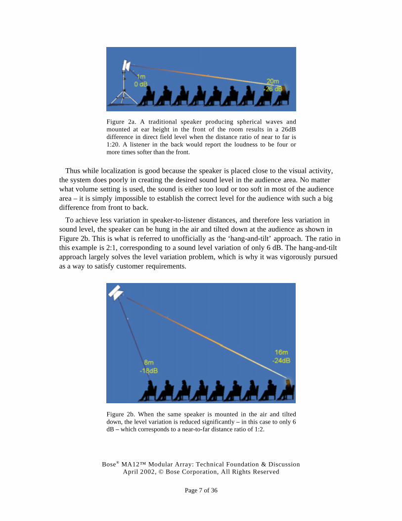
If the 6 dB per doubling of distance behavior is ignored for the moment, and the onlyconsideration were convenience, the easiest place to put a speaker in a typical room would bea position in the front of the room with the speaker aimed toward the audience, as shown inFigure 2a.
This placement, however, has a problem. In the example shown in the figure, the closestlistener is one meter from the speaker, and the farthest listener is twenty meters, a ratio oftwenty to one. This corresponds to a 26 dB difference in sound level, a very large leveldifference corresponding to a perception that the sound at the farthest location is perhaps fouror more times softer than the front.
Bose® MA12™ Modular Array: Technical Foundation & DiscussionApril 2002, © Bose Corporation, All Rights Reserved
Page 7 of 36
Figure 2a. A traditional speaker producing spherical waves andmounted at ear height in the front of the room results in a 26dBdifference in direct field level when the distance ratio of near to far is1:20. A listener in the back would report the loudness to be four ormore times softer than the front.
Thus while localization is good because the speaker is placed close to the visual activity,the system does poorly in creating the desired sound level in the audience area. No matterwhat volume setting is used, the sound is either too loud or too soft in most of the audiencearea – it is simply impossible to establish the correct level for the audience with such a bigdifference from front to back.
To achieve less variation in speaker-to-listener distances, and therefore less variation insound level, the speaker can be hung in the air and tilted down at the audience as shown inFigure 2b. This is what is referred to unofficially as the ‘hang-and-tilt’ approach. The ratio inthis example is 2:1, corresponding to a sound level variation of only 6 dB. The hang-and-tiltapproach largely solves the level variation problem, which is why it was vigorously pursuedas a way to satisfy customer requirements.
Figure 2b. When the same speaker is mounted in the air and tilteddown, the level variation is reduced significantly – in this case to only 6dB – which corresponds to a near-to-far distance ratio of 1:2.
Bose® MA12™ Modular Array: Technical Foundation & DiscussionApril 2002, © Bose Corporation, All Rights Reserved
Page 8 of 36
Of course, as with any engineering solution, the hang-and-tilt approach is not perfect. It hasits strengths and weaknesses as they relate to the goal of cost effectively satisfying the majorcustomer requirements. The details of these strengths and weaknesses are the subject of thenext section.
Strengths of the hang-and-tilt approach
THE strengths of a good hang-and-tilt system are that with it, excellent tonal balance,consistent sound level, and speech intelligibility can be achieved. Moreover, because thespeakers are located up and out of the way, they rarely interfere with sightlines.
Over the years, Bose and others have developed a number of technological solutionsspecifically designed to improve the quality of hang-and-tilt systems. For example, Panaray®
LT speakers are designed with very narrow sound radiation patterns so that designers cancarefully aim them only onto audience areas and avoid reflective walls and ceilings that canproduce the excessive reverberation responsible for diminished speech intelligibility. Thesespeakers also exhibit a very sharp rolloff of sound outside their primary radiation angles,making it easier to combine two or more in such a way that they exhibit a minimum of theinter-speaker interference that can lead to dropouts in sound.
Similarly, the Bose Panaray 502®A loudspeaker represents an important contribution to thefield of hang-and-tilt speakers because it delivers consistent coverage over substantially a fullrange of frequencies using very natural sounding cone-type drivers in a very small package.This speaker is used in literally thousands of venues around the world where customers say itmeets their needs elegantly and unobtrusively.
As a final example of the types of innovations that have led to better hang-and-tilt systems,until very recently it was thought to be difficult or impossible to include control of the lowerfrequencies in hang-and-tilt designs. This lack of control meant that bass sound waves weremore or less allowed to go anywhere within a venue, causing a lack of clarity in music andsome masking of speech (and therefore a reduction of speech intelligibility). Today solutionsexist to control bass frequencies in hang-and-tilt designs with very nearly the same degree ofprecision as the higher frequencies, including a comprehensive technique developed by Bose.These solutions, which employ advanced array theory, have led to noticeable improvementsin the sound quality of systems in which they have been used.
Weaknesses of the hang-and-tilt approach
THE hang-and-tilt approach also has some weaknesses. For example, the designer mustensure that the sound radiation pattern from the speaker being considered is appropriate forthe purpose of covering the audience area. However, the choice of speakers is limited to onlya few, which differ according to their radiation patterns. It is purely coincidence and thereforerare for the designer to find a perfect match between the available radiation patterns and theaudience area. In general, the speaker being considered will have more or less coverage thanwhat is needed.
Bose® MA12™ Modular Array: Technical Foundation & DiscussionApril 2002, © Bose Corporation, All Rights Reserved
Page 9 of 36
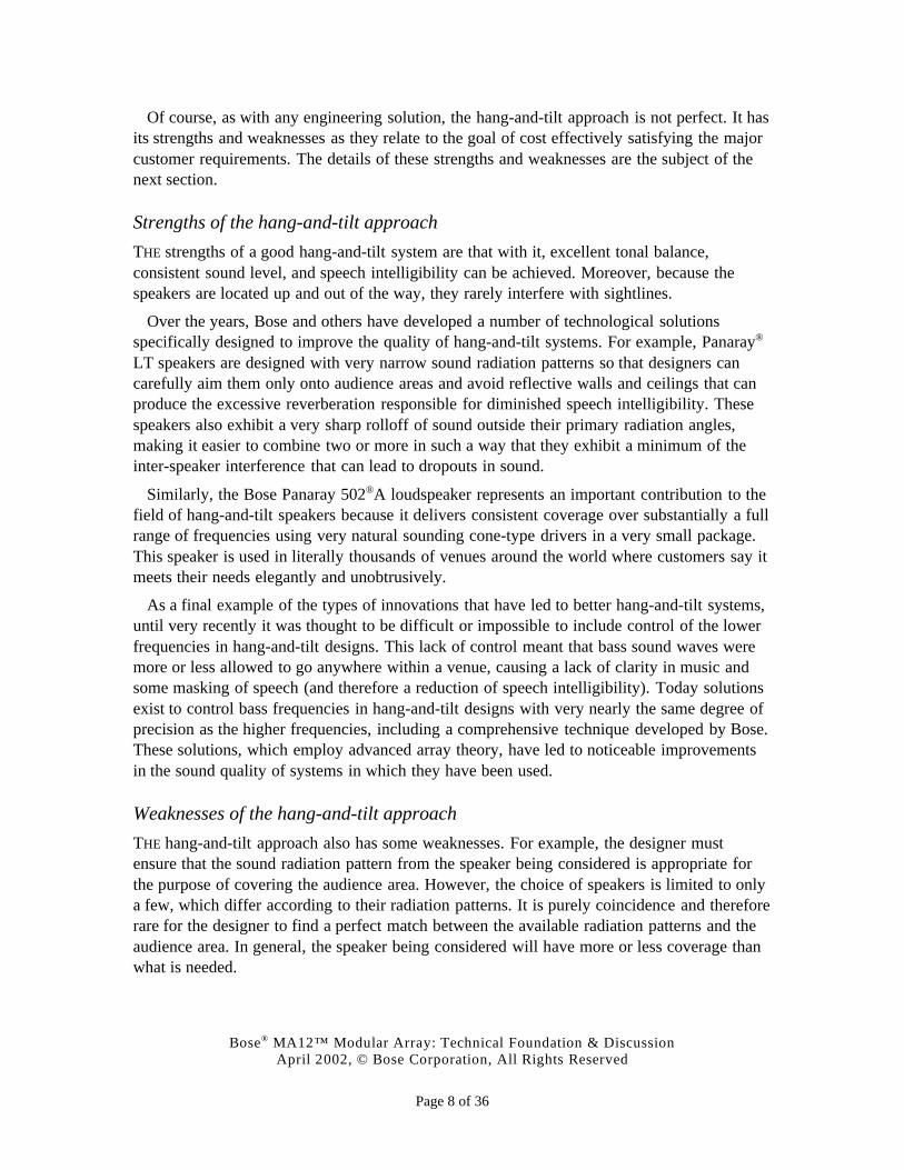
If the speaker’s radiation pattern is too wide for the audience, there is over-coverage asshown in Figure 3a. In these situations, sound radiates to areas other than the audience whereit reflects off of surfaces and arrives at the ears of the listeners as reverberation, which causesdegradation in clarity and intelligibility.
Figure 3a. The effect of choosing a speaker with a radiation patternwider than the audience is shown. Sound striking surfaces other thanthe audience causes unwanted reverberation and reduced musicalclarity and speech intelligibility.
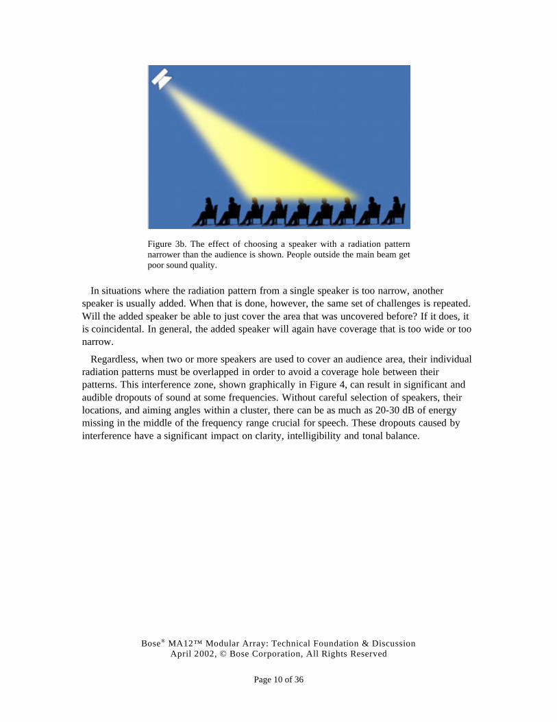
If, on the other hand, the speaker’s radiation pattern is too narrow for the audience, asshown in Figure 3b, people outside the main beam will hear a serious degradation in tonalbalance, level and clarity.
Bose® MA12™ Modular Array: Technical Foundation & DiscussionApril 2002, © Bose Corporation, All Rights Reserved
Page 10 of 36
Figure 3b. The effect of choosing a speaker with a radiation patternnarrower than the audience is shown. People outside the main beam getpoor sound quality.
In situations where the radiation pattern from a single speaker is too narrow, anotherspeaker is usually added. When that is done, however, the same set of challenges is repeated.Will the added speaker be able to just cover the area that was uncovered before? If it does, itis coincidental. In general, the added speaker will again have coverage that is too wide or toonarrow.
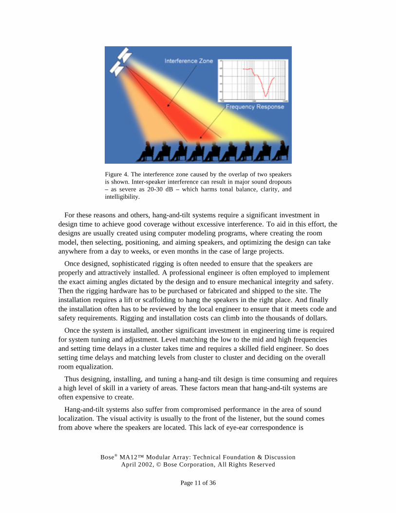
Regardless, when two or more speakers are used to cover an audience area, their individualradiation patterns must be overlapped in order to avoid a coverage hole between theirpatterns. This interference zone, shown graphically in Figure 4, can result in significant andaudible dropouts of sound at some frequencies. Without careful selection of speakers, theirlocations, and aiming angles within a cluster, there can be as much as 20-30 dB of energymissing in the middle of the frequency range crucial for speech. These dropouts caused byinterference have a significant impact on clarity, intelligibility and tonal balance.
Bose® MA12™ Modular Array: Technical Foundation & DiscussionApril 2002, © Bose Corporation, All Rights Reserved
Page 11 of 36
Figure 4. The interference zone caused by the overlap of two speakersis shown. Inter-speaker interference can result in major sound dropouts– as severe as 20-30 dB – which harms tonal balance, clarity, andintelligibility.
For these reasons and others, hang-and-tilt systems require a significant investment indesign time to achieve good coverage without excessive interference. To aid in this effort, thedesigns are usually created using computer modeling programs, where creating the roommodel, then selecting, positioning, and aiming speakers, and optimizing the design can takeanywhere from a day to weeks, or even months in the case of large projects.
Once designed, sophisticated rigging is often needed to ensure that the speakers areproperly and attractively installed. A professional engineer is often employed to implementthe exact aiming angles dictated by the design and to ensure mechanical integrity and safety.Then the rigging hardware has to be purchased or fabricated and shipped to the site. Theinstallation requires a lift or scaffolding to hang the speakers in the right place. And finallythe installation often has to be reviewed by the local engineer to ensure that it meets code andsafety requirements. Rigging and installation costs can climb into the thousands of dollars.
Once the system is installed, another significant investment in engineering time is requiredfor system tuning and adjustment. Level matching the low to the mid and high frequenciesand setting time delays in a cluster takes time and requires a skilled field engineer. So doessetting time delays and matching levels from cluster to cluster and deciding on the overallroom equalization.
Thus designing, installing, and tuning a hang-and tilt design is time consuming and requiresa high level of skill in a variety of areas. These factors mean that hang-and-tilt systems areoften expensive to create.
Hang-and-tilt systems also suffer from compromised performance in the area of soundlocalization. The visual activity is usually to the front of the listener, but the sound comesfrom above where the speakers are located. This lack of eye-ear correspondence is
Bose® MA12™ Modular Array: Technical Foundation & DiscussionApril 2002, © Bose Corporation, All Rights Reserved
Page 12 of 36
disconcerting and creates an ongoing distraction. When given the choice, listeners prefer thesound to come from the same direction as the action.
And finally, service and maintenance is difficult when speakers are hanging in the air.Service usually requires that the floor area be cleared, and a lift or scaffolding employed.This is in general inconvenient and expensive. Sometimes, a facility has to be closed for aday or more in order to gain access to the speakers, or the work must take place late at nightwhen labor costs can be much higher.
Summary
IN summary, the hang and tilt method is effective in meeting customer requirements. But notwithout some compromises in sound quality, usually due to reduced performance in theoverlap areas of speakers and in poor localization performance. Perhaps more important, theprocess of creating and servicing a system is time consuming and requires a high level ofskill in a number of areas, both of which add significantly to the cost of these systems.
Can anything be done about these weaknesses? Or should we only look forward to moreincremental improvements to the hang-and-tilt approach – a new speaker with slightly betterradiation pattern control, or equivalent performance in a somewhat smaller package, orsomewhat easier rigging hardware, for example?
We believe there is a true extension to hang-and-tilt components – a tool for designers thatcan often overcome the weaknesses that have been described. To explain why we have cometo this conclusion, we must return to and examine the fundamental assumption that originallyled the industry to the hang-and-tilt approach.
Bose® MA12™ Modular Array: Technical Foundation & DiscussionApril 2002, © Bose Corporation, All Rights Reserved
Page 13 of 36
THREE KINDS OF SOURCES
AS explained, the hang-and-tilt approach evolved because of a fundamental property of thespeakers used. Namely, the speakers have sound waves that radiate in all directions, in andout, up and down, left and right. And that means that the intensity of sound leaving thesources falls off by 6 dB per doubling of distance. We call these spherical-wave sources. Toprovide consistent sound levels over a widely distributed audience, listeners must be nearlyequidistant to the speaker, and hence the need to raise the speaker into the air over the headsof the listeners.
The obvious question is whether this fundamental 6 dB per doubling of distance property istrue for all sources. The answer is no. There are other kinds of sources that produce differentkinds of sound waves with very different behavior.
Plane waves
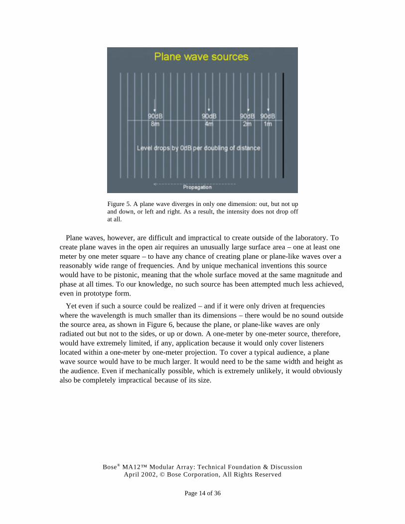
FOR example, we generate plane waves to measure the performance of compression driversin the lab. These waves diverge in only one dimension: out, but not up and down or left andright. As a result, the intensity of a plane wave does not fall off at all with distance1, as shownin Figure 5. In other words, the distance can be doubled and the sound level is the same. Sucha source, therefore, could produce the same sound pressure level in all seats – what would beconsidered ideal coverage.
1 This is an ideal description. In reality, any sound wave, whether spherical or planar, is affected by
environmental effects, such as humidity, temperature and wind.
Bose® MA12™ Modular Array: Technical Foundation & DiscussionApril 2002, © Bose Corporation, All Rights Reserved
Page 14 of 36
Figure 5. A plane wave diverges in only one dimension: out, but not upand down, or left and right. As a result, the intensity does not drop offat all.
Plane waves, however, are difficult and impractical to create outside of the laboratory. Tocreate plane waves in the open air requires an unusually large surface area – one at least onemeter by one meter square – to have any chance of creating plane or plane-like waves over areasonably wide range of frequencies. And by unique mechanical inventions this sourcewould have to be pistonic, meaning that the whole surface moved at the same magnitude andphase at all times. To our knowledge, no such source has been attempted much less achieved,even in prototype form.
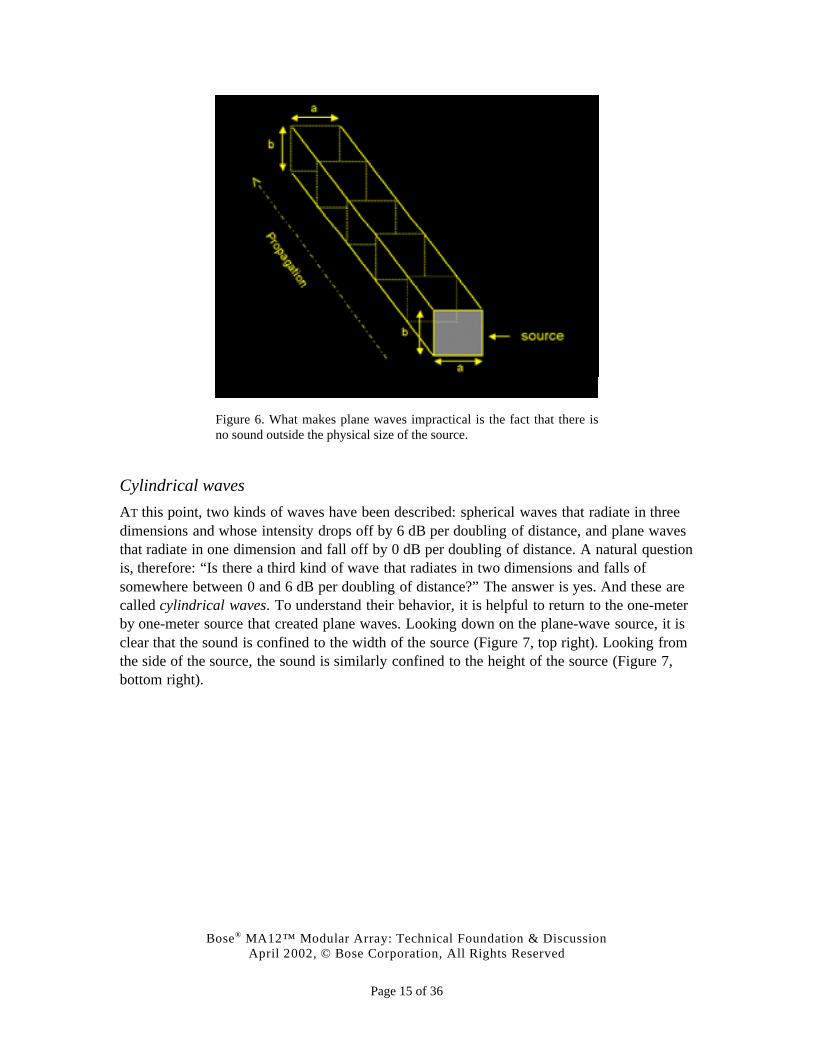
Yet even if such a source could be realized – and if it were only driven at frequencieswhere the wavelength is much smaller than its dimensions – there would be no sound outsidethe source area, as shown in Figure 6, because the plane, or plane-like waves are onlyradiated out but not to the sides, or up or down. A one-meter by one-meter source, therefore,would have extremely limited, if any, application because it would only cover listenerslocated within a one-meter by one-meter projection. To cover a typical audience, a planewave source would have to be much larger. It would need to be the same width and height asthe audience. Even if mechanically possible, which is extremely unlikely, it would obviouslyalso be completely impractical because of its size.
Bose® MA12™ Modular Array: Technical Foundation & DiscussionApril 2002, © Bose Corporation, All Rights Reserved
Page 15 of 36
Figure 6. What makes plane waves impractical is the fact that there isno sound outside the physical size of the source.
Cylindrical waves
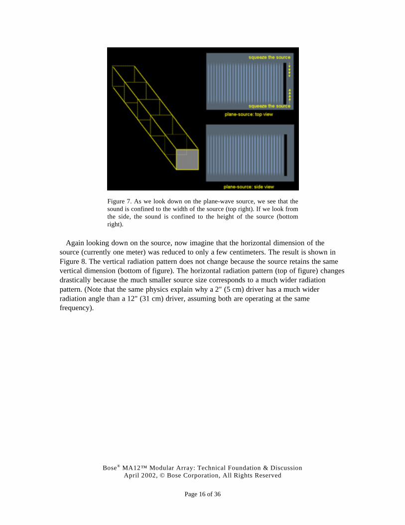
AT this point, two kinds of waves have been described: spherical waves that radiate in threedimensions and whose intensity drops off by 6 dB per doubling of distance, and plane wavesthat radiate in one dimension and fall off by 0 dB per doubling of distance. A natural questionis, therefore: “Is there a third kind of wave that radiates in two dimensions and falls ofsomewhere between 0 and 6 dB per doubling of distance?” The answer is yes. And these arecalled cylindrical waves. To understand their behavior, it is helpful to return to the one-meterby one-meter source that created plane waves. Looking down on the plane-wave source, it isclear that the sound is confined to the width of the source (Figure 7, top right). Looking fromthe side of the source, the sound is similarly confined to the height of the source (Figure 7,bottom right).
Bose® MA12™ Modular Array: Technical Foundation & DiscussionApril 2002, © Bose Corporation, All Rights Reserved
Page 16 of 36
Figure 7. As we look down on the plane-wave source, we see that thesound is confined to the width of the source (top right). If we look fromthe side, the sound is confined to the height of the source (bottomright).
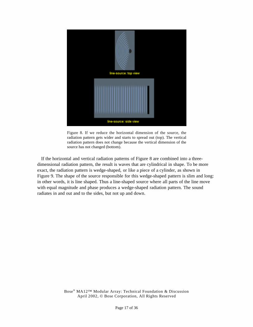
Again looking down on the source, now imagine that the horizontal dimension of thesource (currently one meter) was reduced to only a few centimeters. The result is shown inFigure 8. The vertical radiation pattern does not change because the source retains the samevertical dimension (bottom of figure). The horizontal radiation pattern (top of figure) changesdrastically because the much smaller source size corresponds to a much wider radiationpattern. (Note that the same physics explain why a 2" (5 cm) driver has a much widerradiation angle than a 12" (31 cm) driver, assuming both are operating at the samefrequency).
Bose® MA12™ Modular Array: Technical Foundation & DiscussionApril 2002, © Bose Corporation, All Rights Reserved
Page 17 of 36
Figure 8. If we reduce the horizontal dimension of the source, theradiation pattern gets wider and starts to spread out (top). The verticalradiation pattern does not change because the vertical dimension of thesource has not changed (bottom).
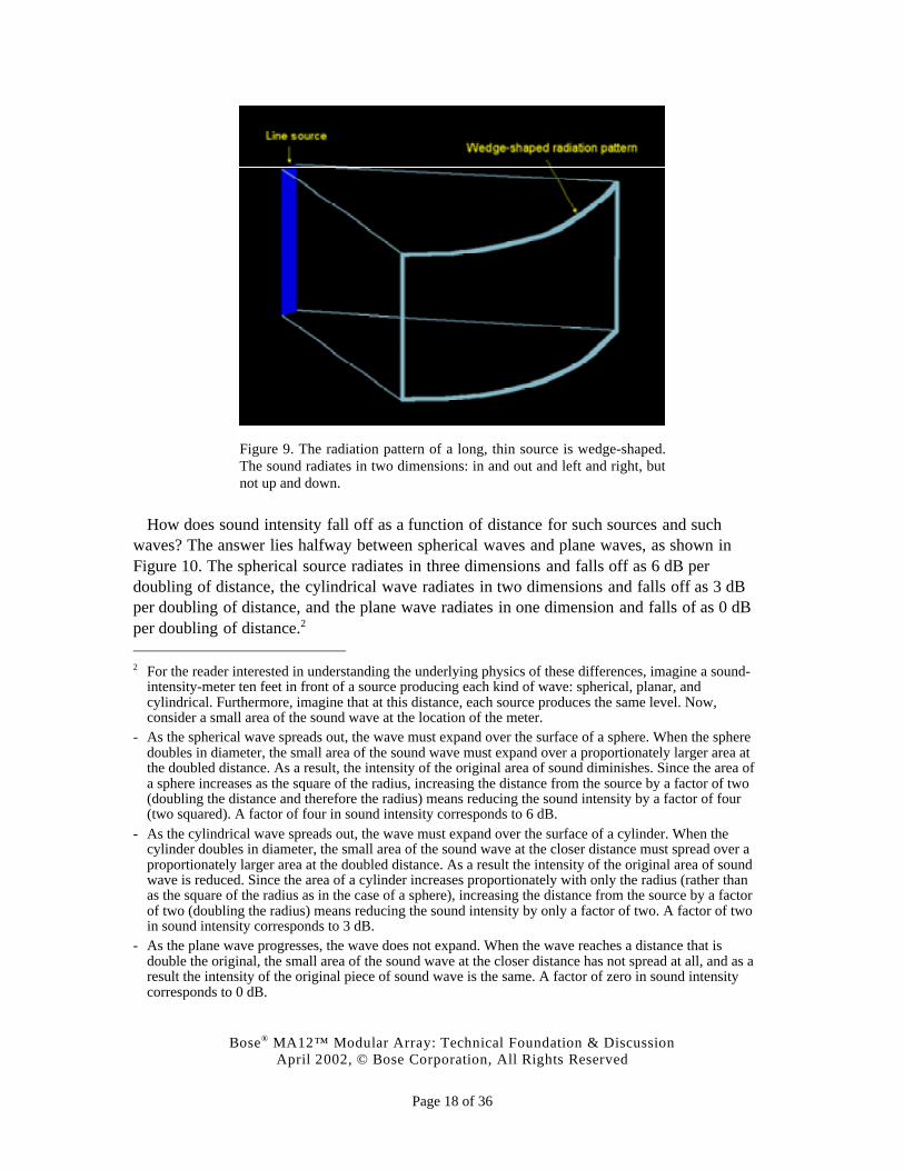
If the horizontal and vertical radiation patterns of Figure 8 are combined into a three-dimensional radiation pattern, the result is waves that are cylindrical in shape. To be moreexact, the radiation pattern is wedge-shaped, or like a piece of a cylinder, as shown inFigure 9. The shape of the source responsible for this wedge-shaped pattern is slim and long:in other words, it is line shaped. Thus a line-shaped source where all parts of the line movewith equal magnitude and phase produces a wedge-shaped radiation pattern. The soundradiates in and out and to the sides, but not up and down.
Bose® MA12™ Modular Array: Technical Foundation & DiscussionApril 2002, © Bose Corporation, All Rights Reserved
Page 18 of 36
Figure 9. The radiation pattern of a long, thin source is wedge-shaped.The sound radiates in two dimensions: in and out and left and right, butnot up and down.
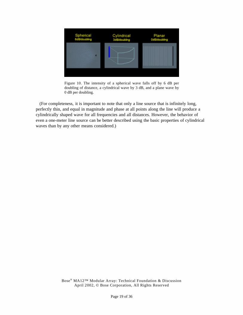
How does sound intensity fall off as a function of distance for such sources and suchwaves? The answer lies halfway between spherical waves and plane waves, as shown inFigure 10. The spherical source radiates in three dimensions and falls off as 6 dB perdoubling of distance, the cylindrical wave radiates in two dimensions and falls off as 3 dBper doubling of distance, and the plane wave radiates in one dimension and falls of as 0 dBper doubling of distance.2
2 For the reader interested in understanding the underlying physics of these differences, imagine a sound-
intensity-meter ten feet in front of a source producing each kind of wave: spherical, planar, andcylindrical. Furthermore, imagine that at this distance, each source produces the same level. Now,consider a small area of the sound wave at the location of the meter.
- As the spherical wave spreads out, the wave must expand over the surface of a sphere. When the spheredoubles in diameter, the small area of the sound wave must expand over a proportionately larger area atthe doubled distance. As a result, the intensity of the original area of sound diminishes. Since the area ofa sphere increases as the square of the radius, increasing the distance from the source by a factor of two(doubling the distance and therefore the radius) means reducing the sound intensity by a factor of four(two squared). A factor of four in sound intensity corresponds to 6 dB.
- As the cylindrical wave spreads out, the wave must expand over the surface of a cylinder. When thecylinder doubles in diameter, the small area of the sound wave at the closer distance must spread over aproportionately larger area at the doubled distance. As a result the intensity of the original area of soundwave is reduced. Since the area of a cylinder increases proportionately with only the radius (rather thanas the square of the radius as in the case of a sphere), increasing the distance from the source by a factorof two (doubling the radius) means reducing the sound intensity by only a factor of two. A factor of twoin sound intensity corresponds to 3 dB.
- As the plane wave progresses, the wave does not expand. When the wave reaches a distance that isdouble the original, the small area of the sound wave at the closer distance has not spread at all, and as aresult the intensity of the original piece of sound wave is the same. A factor of zero in sound intensitycorresponds to 0 dB.
Bose® MA12™ Modular Array: Technical Foundation & DiscussionApril 2002, © Bose Corporation, All Rights Reserved
Page 19 of 36
Figure 10. The intensity of a spherical wave falls off by 6 dB perdoubling of distance, a cylindrical wave by 3 dB, and a plane wave by0 dB per doubling.
(For completeness, it is important to note that only a line source that is infinitely long,perfectly thin, and equal in magnitude and phase at all points along the line will produce acylindrically shaped wave for all frequencies and all distances. However, the behavior ofeven a one-meter line source can be better described using the basic properties of cylindricalwaves than by any other means considered.)
Bose® MA12™ Modular Array: Technical Foundation & DiscussionApril 2002, © Bose Corporation, All Rights Reserved
Page 20 of 36
APPLYING LINE SOURCES TO SOUND SYSTEM DESIGN
THE 3 dB per doubling behavior of cylindrical waves is of special interest in sound systemdesign because it is so much more gradual than the 6 dB per doubling behavior thatmotivated us to hang and tilt speakers. On the other hand, so was the 0 dB per doublingbehavior of plane waves, but unfortunately, producing them was impractical in real life. Is itmore practical to produce cylindrical waves? Or are there problems that will rule this out too?If such a source can be realized, would it really do a good job at meeting customerrequirements?
Source shape and sound output capability
TO begin, a source that produces cylindrical waves does not have to be rejected for the samereasons a plane-wave source was rejected. A cylindrical-wave source must be as tall as theaudience, but not as wide, since the wide horizontal radiation pattern can be relied on tocover an audience distributed side to side; a tall, slim source, resulting in wide side-to-sideradiation, can cover a typical audience.
Second, with modern transducer technology, there is no reason that a line source can notproduce a balanced frequency response at the kind of output levels required in manyapplications. Major improvements in transducer technology (including many introduced byBose) mean that it is no longer true that the small transducers needed to fit into a slim line-shaped source lack the correct balance of frequencies or necessary output capacity. A full,balanced frequency response and very high output is now possible from speakers no largerthat a tea cup. Therefore, concerns about frequency response and output are also not reasonsto reject the line source.
Meeting the primary customer requirements
IN principal – in other words without regard to the specifics of any particular implementation– would a line-shaped source radiating cylindrical or near-cylindrical waves be a good choicefor meeting the major customer requirements listed earlier?
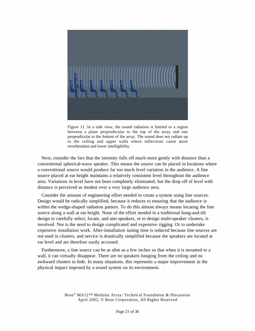
Re-examination of the side view of the radiation pattern of a line source, shown in Figure11, reveals that sound does not radiate up and down, but rather is confined to a regionbetween a plane perpendicular to the top of the array and one perpendicular to the bottom.When such a source is placed in a room, it means that sound will not radiate up and down andtherefore will not radiate to the ceiling and upper walls, where reflections contribute to theamount of reverberation and therefore to the degradation of music clarity and speechintelligibility. Such a source would be therefore ideally suited to environments with longerreverberation times such as churches, auditoriums, airports, hallways and so on.
Bose® MA12™ Modular Array: Technical Foundation & DiscussionApril 2002, © Bose Corporation, All Rights Reserved
Page 21 of 36
Figure 11. In a side view, the sound radiation is limited to a regionbetween a plane perpendicular to the top of the array and oneperpendicular to the bottom of the array. The sound does not radiate upto the ceiling and upper walls where reflections cause morereverberation and lower intelligibility.
Next, consider the fact that the intensity falls off much more gently with distance than aconventional spherical-wave speaker. This means the source can be placed in locations wherea conventional source would produce far too much level variation in the audience. A linesource placed at ear height maintains a relatively consistent level throughout the audiencearea. Variations in level have not been completely eliminated, but the drop off of level withdistance is perceived as modest over a very large audience area.
Consider the amount of engineering effort needed to create a system using line sources.Design would be radically simplified, because it reduces to ensuring that the audience iswithin the wedge-shaped radiation pattern. To do this almost always means locating the linesource along a wall at ear height. None of the effort needed in a traditional hang-and-tiltdesign to carefully select, locate, and aim speakers, or to design multi-speaker clusters, isinvolved. Nor is the need to design complicated and expensive rigging. Or to undertakeexpensive installation work. After-installation tuning time is reduced because line sources arenot used in clusters, and service is drastically simplified because the speakers are located atear level and are therefore easily accessed.
Furthermore, a line source can be as slim as a few inches so that when it is mounted to awall, it can virtually disappear. There are no speakers hanging from the ceiling and noawkward clusters to hide. In many situations, this represents a major improvement in thephysical impact imposed by a sound system on its environment.
Bose® MA12™ Modular Array: Technical Foundation & DiscussionApril 2002, © Bose Corporation, All Rights Reserved
Page 22 of 36
Thus a line-shaped source has the potential to satisfy all of the major customerrequirements in ways that often overcome some of the weaknesses of the hang-and-tiltapproach. As such, a well-executed line-shaped source would not be simply an incrementalimprovement to the well-worn products and techniques used in hang-and-tilt designs. Itwould represent an important new tool that would significantly increase the options designershave in many venues. The potential would exist to satisfy the basic customer requirementsand to do so in many cases at substantially less cost. Such a source would therefore representsomething more significant than an incremental advancement. The remainder of thisdocument is devoted to providing evidence that such an advancement has been made.
BOSE MA12™ MODULAR ARRAY
THE Bose MA12 array is a one-meter tall speaker module consisting of twelve closely-spacedhigh-output 2.2" (6 cm) drivers operating over the frequency range from 120 Hz to 16 kHz. Aone-meter module was chosen because it is tall enough to produce the desired wedge-shapedradiation pattern, short enough to be easily handled, and modular so that longer line sourcescan easily be constructed.
In the MA12, the drivers chosen exhibit pistonic behavior up to higher frequencies thanwhat could be achieved with larger drivers of similar quality, a desirable feature when thegoal is to create the wedge-shaped pattern over a very wide range of frequencies.
The small driver diameter was also chosen so that the source would have very widehorizontal dispersion. The MA12 has 160° of coverage up to very high frequencies. This isimportant because when the audience is close – a definite possibility because the gentlechange in level with distance means it is not too loud close to the speaker – it tends also to bedistributed over a wide angle.
The ultra-slim profile of the MA12, also a consequence of the driver chosen, means that thespeaker blends into almost any environment. A single array module has a surprising height-to-width aspect ratio of 12:1. If two modules are used, this increases to 24:1. Taken togetherwith the fact that the speaker is available in black and white and can also be easily painted,we believe it is fair to say that it will virtually disappear into most rooms.
Bose® MA12™ Modular Array: Technical Foundation & DiscussionApril 2002, © Bose Corporation, All Rights Reserved
Page 23 of 36
OTHER LINE-SHAPED SOURCES
IN the last section, the unique decisions and choices Bose made in designing the innovativeMA12™ modular array were discussed. However, there are other line-shaped sources alreadyavailable. How do they compare to the MA12?
Column speakers
SOME line-shaped sources have been around for a long time. A number of well-knownmanufacturers have developed versions, called column speakers, as early as the 1940’s. Thespeakers had limited frequency response and output. In other applications where better tonalbalance and higher levels were needed they simply could not be met by these columnspeakers. None could be considered high performance speakers by today’s standards.
Sources using electrostatic, ribbon, or planar magnetic transducers
ANOTHER class of line-shaped speakers uses electrostatic, ribbon or planar magnetictransducers. In general, these transducers do not produce a full-range frequency response, butonly covers from about 3-500Hz and up. To cover the range of lower frequencies up to about300-500Hz, the transducers are augmented by traditional sources typically using woofers in asealed enclosure at the bottom of each speaker.
In some implementations, the ribbon emits sound both to the front and the back, so high-energy sound from the rear of the speaker is directed away from the audience and onto wallsurfaces where reflections add to reverberation and degrade clarity and intelligibility. Manyof these speakers, while looking promising on paper, are not designed for professionalapplications, require a base to extend the frequency response, and radiate equal amounts ofsound to the rear.
DSP-based arrays
THERE IS another class of arrays that are using digital signal processing (DSP) to control andsteer the speakers’ radiation patterns. Most of these arrays use 4" (10.2 cm) or largertransducers. The drivers are either spaced closely in a line, or in a scheme where spacingvaries. The speakers have built in multi-channel signal processing and amplification.
There are some obvious differences between these arrays and the MA12. First, thesespeakers are using larger drivers resulting in an appearance that is significantly wider than theMA12. The larger drivers also have narrower horizontal coverage, which can be adisadvantage with audiences located close to the speaker.
The biggest difference is these speakers’ use of DSP to control the radiation pattern of thearray, and which also makes the cost much higher than the MA12. Drivers get differentsignals and hence require their own signal processing and amplification. This makes itpossible to steer the radiation pattern at middle and higher frequencies. For example, the

Bose® MA12™ Modular Array: Technical Foundation & DiscussionApril 2002, © Bose Corporation, All Rights Reserved
Page 24 of 36
speaker can be mounted high on a wall and the radiation pattern steered down to the audiencearea on the floor.
Why did Bose elect not to use DSP in the MA12™ Modular Array? First, in our solution wesought a pure wedge-shaped radiation pattern, not a variety of different, selectable radiationpatterns. We did this so that we could cover a large audience area from a speaker located atear height. For this, no DSP is needed and thus none is used. Second, if a speaker positionedhigh in the air is needed, then this seems to us an ideal application for traditional hang-and-tilt speakers, which have shown in countless facilities to meet basic customer requirements ata fraction of the cost of using many channels of DSP and amplification to achieve the sameeffect.
High-output arrays for touring systems
THERE is a class of speakers that use much larger and more powerful transducers in muchlarger enclosures than what is used in the MA12. As a result, these speakers are much larger,and more expensive than the MA12. As a result– in addition to the differences in transducercomplements - the most important difference between these speakers and the MA12 is themarkets for which they are intended. They are very clearly aimed at large touring soundsystems for musical groups playing in stadia and arenas. The MA12 is aimed at the heart ofthe installed sound market. While philosophically similar, these products are far too large, fartoo powerful, and far too expensive for our target markets.
Column like speakers
THE last category is speakers that look like line arrays but really are not. They are reallyspherical-wave sources housed in line-shaped enclosures. This is not to say that themanufacturers are making false claims, but merely to note that a line-shaped source may nothouse an acoustical design intended to behave like the line sources we have discussed here.
An example of these speakers uses four 4" (10.2 cm) drivers and three tweeters in a line.
This design and others like it, while having features that can have advantages in certainapplications, do not attempt to achieve pistonic behavior over the length of the line and overa wide range of frequencies. The four drivers in this configuration could be too widely spacedfor this purpose, for example. Similarly the tweeter array in the middle may not be tallenough to produce a wedge-shaped radiation pattern at the lower part of its frequency range;the array is simply not tall enough, and the drivers not densely- packed enough. Thesespeakers behave more like conventional loudspeakers, albeit with narrower vertical radiationpatterns.
Bose® MA12™ Modular Array: Technical Foundation & DiscussionApril 2002, © Bose Corporation, All Rights Reserved
Page 25 of 36
Summary
IN none of the existing approaches have the inventors taken the same design approaches asBose in the case of the MA12™ array. The goals in creating the MA12 were exceptionallyhigh acoustic output from an ultra-thin baffle area, a wedge-shaped radiation pattern andgentle fall off of sound characteristic of cylindrical waves, and wide horizontal dispersion ina lightweight, modular, architecturally unobtrusive, and affordable package. It is our beliefthat we have succeeded in this regard. However, we welcome the fact that designers andcustomers alike will be able to judge for themselves the degree to which they agree with ourclaims. We recognize that the success of the design depends on their judgement, not ours.
DESIGNING WITH THE MA12
IN this section, some of the basic rules for applying the MA12 are presented. These rules areintuitive given the wedge-shaped radiation pattern of this speaker. For a listener to becovered with sound from a source with a wedge-shaped radiation pattern, his or her ears mustbe contained between two imaginary 160° wedge-shaped surfaces, one extending from thetop of the speaker, and the other extending from the bottom.
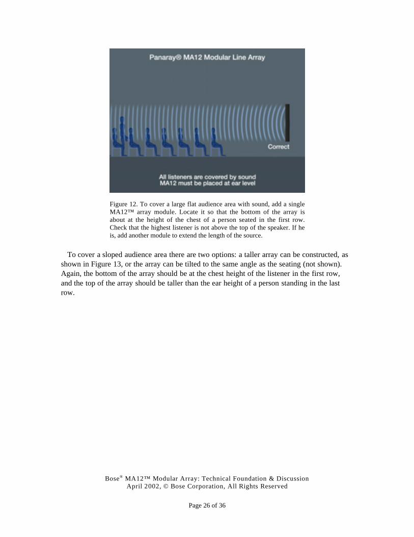
To cover a large flat audience area with sound, a single MA12 module is placed as shownin Figure 12. It is located so that the bottom of the array is about at the height of the chest ofa person seated in the first row. Other modules may be added if necessary until the top of thearray covers the head of a listener in the last row. (In the figure, only one module is used.)
Bose® MA12™ Modular Array: Technical Foundation & DiscussionApril 2002, © Bose Corporation, All Rights Reserved
Page 26 of 36
Figure 12. To cover a large flat audience area with sound, add a singleMA12™ array module. Locate it so that the bottom of the array isabout at the height of the chest of a person seated in the first row.Check that the highest listener is not above the top of the speaker. If heis, add another module to extend the length of the source.
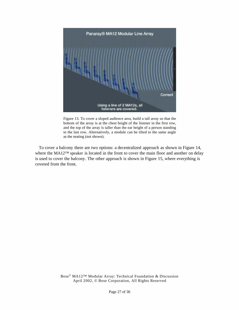
To cover a sloped audience area there are two options: a taller array can be constructed, asshown in Figure 13, or the array can be tilted to the same angle as the seating (not shown).Again, the bottom of the array should be at the chest height of the listener in the first row,and the top of the array should be taller than the ear height of a person standing in the lastrow.
Bose® MA12™ Modular Array: Technical Foundation & DiscussionApril 2002, © Bose Corporation, All Rights Reserved
Page 27 of 36
Figure 13. To cover a sloped audience area, build a tall array so that thebottom of the array is at the chest height of the listener in the first row,and the top of the array is taller than the ear height of a person standingin the last row. Alternatively, a module can be tilted to the same angleas the seating (not shown).
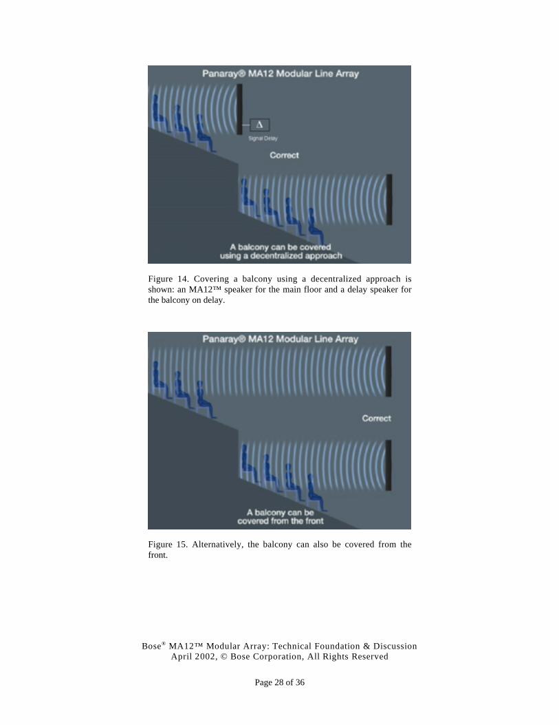
To cover a balcony there are two options: a decentralized approach as shown in Figure 14,where the MA12™ speaker is located in the front to cover the main floor and another on delayis used to cover the balcony. The other approach is shown in Figure 15, where everything iscovered from the front.
Bose® MA12™ Modular Array: Technical Foundation & DiscussionApril 2002, © Bose Corporation, All Rights Reserved
Page 28 of 36
Figure 14. Covering a balcony using a decentralized approach isshown: an MA12™ speaker for the main floor and a delay speaker forthe balcony on delay.
Figure 15. Alternatively, the balcony can also be covered from thefront.
Bose® MA12™ Modular Array: Technical Foundation & DiscussionApril 2002, © Bose Corporation, All Rights Reserved
Page 29 of 36
SAMPLE PROJECTS
IN the end, what convinced Bose to develop the MA12™ speaker was the enthusiasticfeedback we received from many of our field engineers around the world whom for severalyears had been designing and installing custom line arrays. What are now obviousapplications for the MA12 – places of worship, pedestrian concourses, auditoriums,nightclubs, performing arts centers, restaurants, retail outlets, conference centers, andtransportation buildings – were all tested by field engineers using custom arrays. It isinstructive to examine some of these projects as they clearly convey the breadth ofapplications for these sources, and help support the basic conclusions of this document. Itshould be noted that if any of these projects were undertaken today, they would be designedwith the MA12.
Saint Peters Basilica, Vatican City (Rome, Italy)
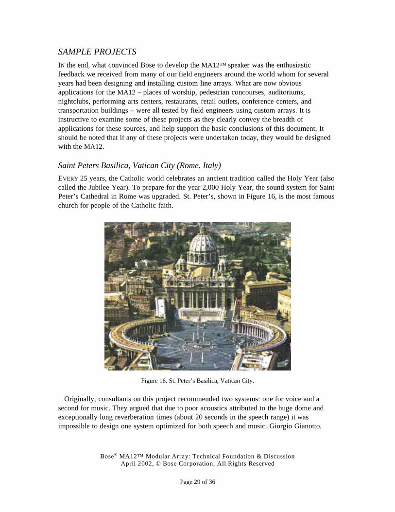
EVERY 25 years, the Catholic world celebrates an ancient tradition called the Holy Year (alsocalled the Jubilee Year). To prepare for the year 2,000 Holy Year, the sound system for SaintPeter’s Cathedral in Rome was upgraded. St. Peter’s, shown in Figure 16, is the most famouschurch for people of the Catholic faith.
Figure 16. St. Peter’s Basilica, Vatican City.
Originally, consultants on this project recommended two systems: one for voice and asecond for music. They argued that due to poor acoustics attributed to the huge dome andexceptionally long reverberation times (about 20 seconds in the speech range) it wasimpossible to design one system optimized for both speech and music. Giorgio Gianotto,
Bose® MA12™ Modular Array: Technical Foundation & DiscussionApril 2002, © Bose Corporation, All Rights Reserved
Page 30 of 36
Bose’s Technical Director in Italy, was able to prove using Bose Modeler® and Auditioner®
that one system could perform both functions, a tremendous savings for the Vatican.
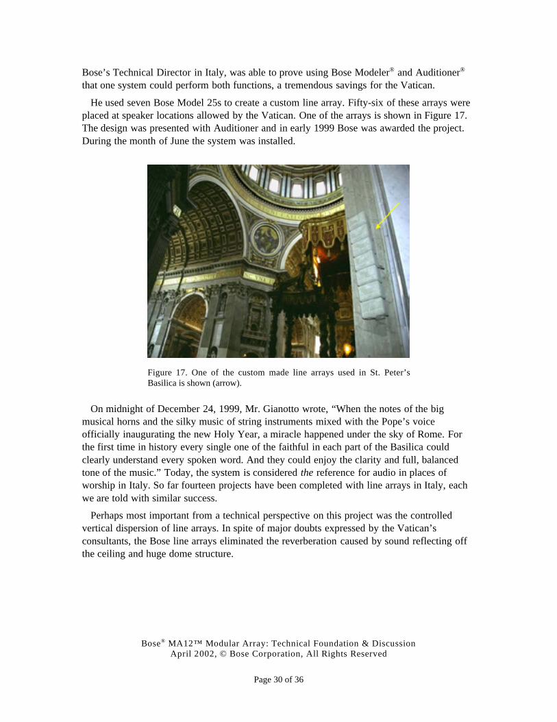
He used seven Bose Model 25s to create a custom line array. Fifty-six of these arrays wereplaced at speaker locations allowed by the Vatican. One of the arrays is shown in Figure 17.The design was presented with Auditioner and in early 1999 Bose was awarded the project.During the month of June the system was installed.
Figure 17. One of the custom made line arrays used in St. Peter’sBasilica is shown (arrow).
On midnight of December 24, 1999, Mr. Gianotto wrote, “When the notes of the bigmusical horns and the silky music of string instruments mixed with the Pope’s voiceofficially inaugurating the new Holy Year, a miracle happened under the sky of Rome. Forthe first time in history every single one of the faithful in each part of the Basilica couldclearly understand every spoken word. And they could enjoy the clarity and full, balancedtone of the music.” Today, the system is considered the reference for audio in places ofworship in Italy. So far fourteen projects have been completed with line arrays in Italy, eachwe are told with similar success.
Perhaps most important from a technical perspective on this project was the controlledvertical dispersion of line arrays. In spite of major doubts expressed by the Vatican’sconsultants, the Bose line arrays eliminated the reverberation caused by sound reflecting offthe ceiling and huge dome structure.
Bose® MA12™ Modular Array: Technical Foundation & DiscussionApril 2002, © Bose Corporation, All Rights Reserved
Page 31 of 36
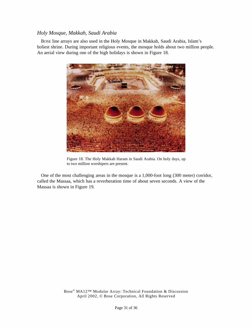
Holy Mosque, Makkah, Saudi Arabia
BOSE line arrays are also used in the Holy Mosque in Makkah, Saudi Arabia, Islam’sholiest shrine. During important religious events, the mosque holds about two million people.An aerial view during one of the high holidays is shown in Figure 18.
Figure 18. The Holy Makkah Haram in Saudi Arabia. On holy days, upto two million worshipers are present.
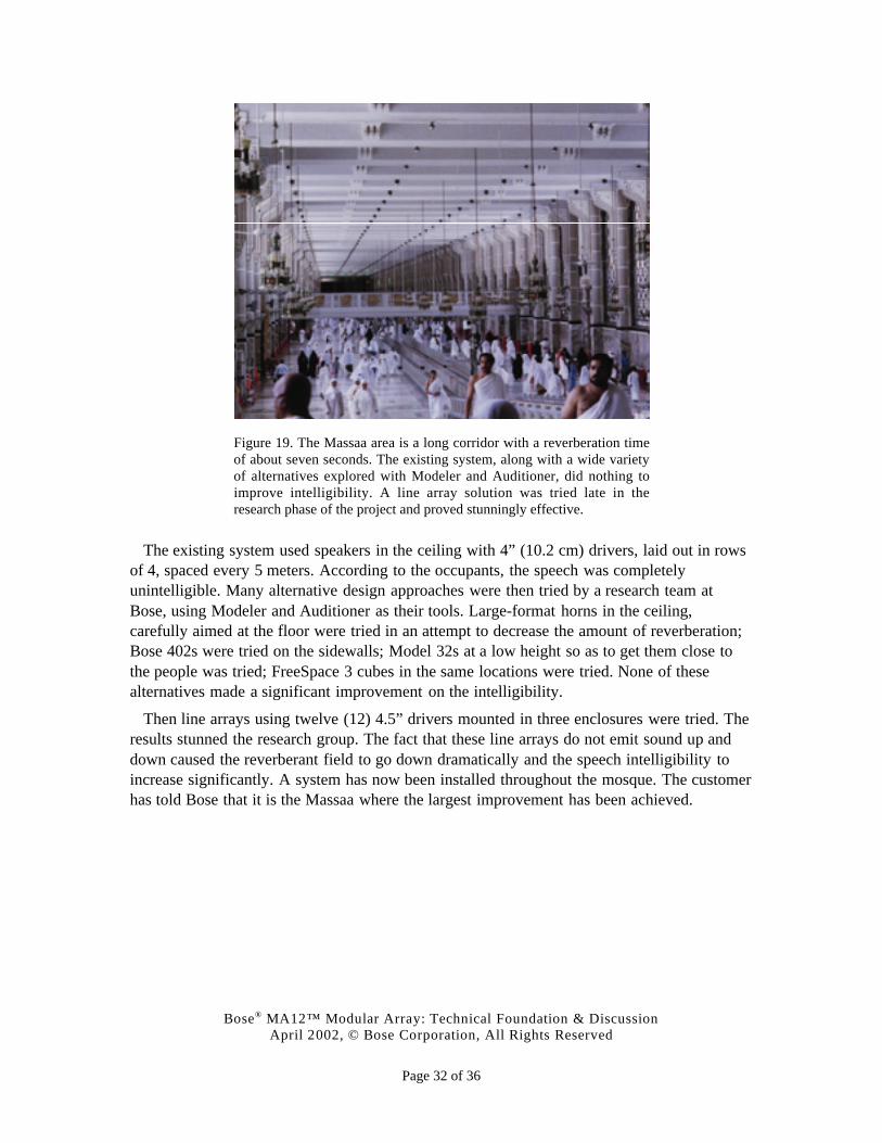
One of the most challenging areas in the mosque is a 1,000-foot long (300 meter) corridor,called the Massaa, which has a reverberation time of about seven seconds. A view of theMassaa is shown in Figure 19.
Bose® MA12™ Modular Array: Technical Foundation & DiscussionApril 2002, © Bose Corporation, All Rights Reserved
Page 32 of 36
Figure 19. The Massaa area is a long corridor with a reverberation timeof about seven seconds. The existing system, along with a wide varietyof alternatives explored with Modeler and Auditioner, did nothing toimprove intelligibility. A line array solution was tried late in theresearch phase of the project and proved stunningly effective.
The existing system used speakers in the ceiling with 4” (10.2 cm) drivers, laid out in rowsof 4, spaced every 5 meters. According to the occupants, the speech was completelyunintelligible. Many alternative design approaches were then tried by a research team atBose, using Modeler and Auditioner as their tools. Large-format horns in the ceiling,carefully aimed at the floor were tried in an attempt to decrease the amount of reverberation;Bose 402s were tried on the sidewalls; Model 32s at a low height so as to get them close tothe people was tried; FreeSpace 3 cubes in the same locations were tried. None of thesealternatives made a significant improvement on the intelligibility.
Then line arrays using twelve (12) 4.5” drivers mounted in three enclosures were tried. Theresults stunned the research group. The fact that these line arrays do not emit sound up anddown caused the reverberant field to go down dramatically and the speech intelligibility toincrease significantly. A system has now been installed throughout the mosque. The customerhas told Bose that it is the Massaa where the largest improvement has been achieved.
Bose® MA12™ Modular Array: Technical Foundation & DiscussionApril 2002, © Bose Corporation, All Rights Reserved
Page 33 of 36
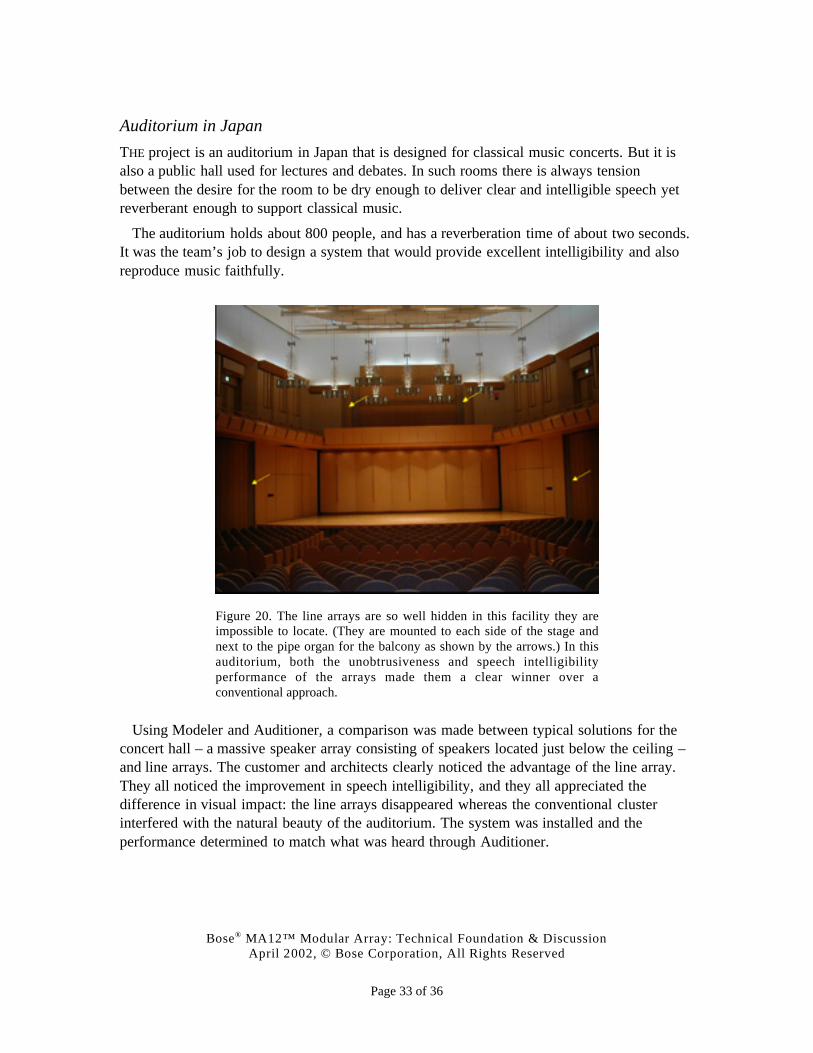
Auditorium in Japan
THE project is an auditorium in Japan that is designed for classical music concerts. But it isalso a public hall used for lectures and debates. In such rooms there is always tensionbetween the desire for the room to be dry enough to deliver clear and intelligible speech yetreverberant enough to support classical music.
The auditorium holds about 800 people, and has a reverberation time of about two seconds.It was the team’s job to design a system that would provide excellent intelligibility and alsoreproduce music faithfully.
Figure 20. The line arrays are so well hidden in this facility they areimpossible to locate. (They are mounted to each side of the stage andnext to the pipe organ for the balcony as shown by the arrows.) In thisauditorium, both the unobtrusiveness and speech intelligibilityperformance of the arrays made them a clear winner over aconventional approach.
Using Modeler and Auditioner, a comparison was made between typical solutions for theconcert hall – a massive speaker array consisting of speakers located just below the ceiling –and line arrays. The customer and architects clearly noticed the advantage of the line array.They all noticed the improvement in speech intelligibility, and they all appreciated thedifference in visual impact: the line arrays disappeared whereas the conventional clusterinterfered with the natural beauty of the auditorium. The system was installed and theperformance determined to match what was heard through Auditioner.
Bose® MA12™ Modular Array: Technical Foundation & DiscussionApril 2002, © Bose Corporation, All Rights Reserved
Page 34 of 36
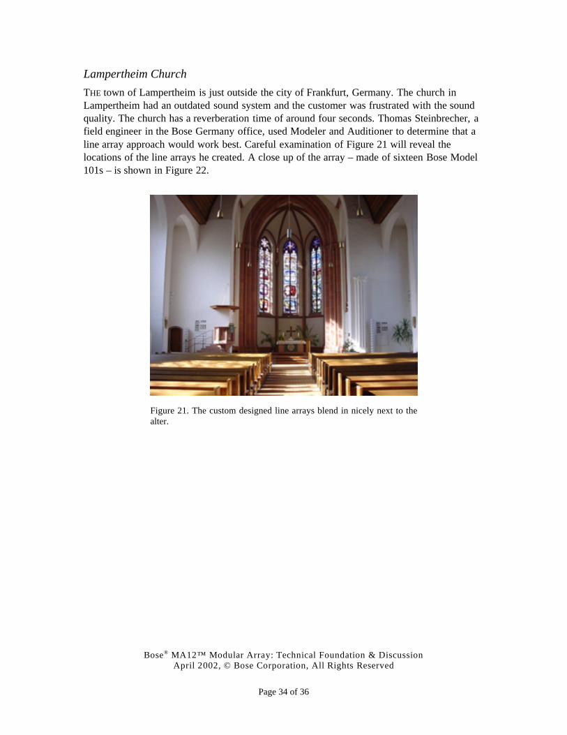
Lampertheim Church
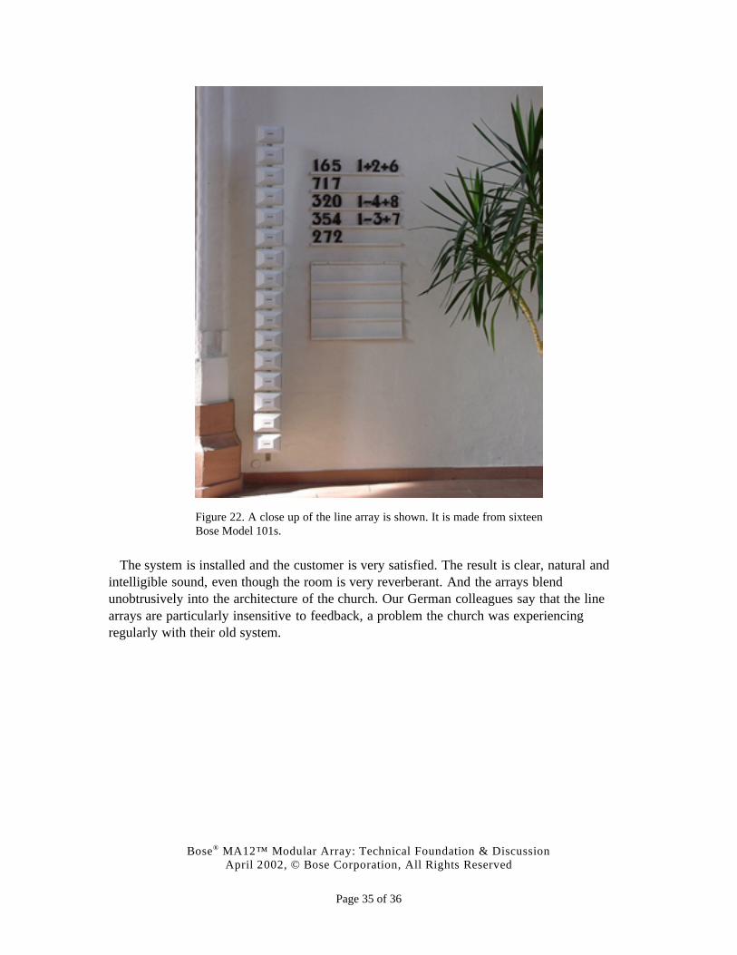
THE town of Lampertheim is just outside the city of Frankfurt, Germany. The church inLampertheim had an outdated sound system and the customer was frustrated with the soundquality. The church has a reverberation time of around four seconds. Thomas Steinbrecher, afield engineer in the Bose Germany office, used Modeler and Auditioner to determine that aline array approach would work best. Careful examination of Figure 21 will reveal thelocations of the line arrays he created. A close up of the array – made of sixteen Bose Model101s – is shown in Figure 22.
Figure 21. The custom designed line arrays blend in nicely next to thealter.
Bose® MA12™ Modular Array: Technical Foundation & DiscussionApril 2002, © Bose Corporation, All Rights Reserved
Page 35 of 36
Figure 22. A close up of the line array is shown. It is made from sixteenBose Model 101s.
The system is installed and the customer is very satisfied. The result is clear, natural andintelligible sound, even though the room is very reverberant. And the arrays blendunobtrusively into the architecture of the church. Our German colleagues say that the linearrays are particularly insensitive to feedback, a problem the church was experiencingregularly with their old system.
Bose® MA12™ Modular Array: Technical Foundation & DiscussionApril 2002, © Bose Corporation, All Rights Reserved
Page 36 of 36
CONCLUSION
FUNDAMENTAL assumptions about the behavior of loudspeakers led the professional soundindustry to use a single approach to sound system design for much of the past fifty years. Thehang-and-tilt approach, while effective in meeting most of the basic customer requirements,is also an approach that requires an extensive engineering effort to do properly, is oftenexpensive to install, is invasive to the appearance of a facility, and is difficult to service.
Our intent has been to show that the fundamental assumption leading to hang-and-tilt as thedominant approach is not true for all sound sources. And at least one of the alternatives – linesources – has properties that address many of the weaknesses of the hang-and-tilt approach,and are practical to build.
Bose has undertaken the development of such a source based on the extraordinary resultsobtained with custom-made versions of line sources in a wide variety of facilities throughoutthe world, including acoustically challenging facilities. The result is an unobtrusive, yetacoustically powerful speaker that can be used to satisfy basic customer requirements inmany facilities and often at significantly less cost than a traditional hang-and-tilt system.
It is our belief that such a source is capable of significantly extending the options availableto sound designers, and as such represents an important extension to and enhancement ofwhat is currently possible.