book 7 keypad version
TRANSCRIPT


Recommended Bolt Torques for Flanged Mag Meters.
ANSI ANSI ANSI ANSIClass Class Class Class
Size 150 300 600 9001/2 10 15 15 20 10 14 20 271 10 15 15 20 25 34 40 54
1 1/2 15 20 25 35 45 61 85 1152 25 35 15 20 30 41 60 813 40 55 30 40 70 95 115 1564 30 40 45 60 125 169 225 3055 45 60 75 100 195 264 350 4756 60 80 65 90 180 244 295 4008 75 100 120 160 305 414 560 759
10 70 95 150 200 365 495 605 82012 95 130 230 310 405 549 660 89514 120 160 215 290 515 698 840 1139
16 115 155 310 420 740 1003 1180 1600
18 175 240 335 455 1025 1390 1770 2400
20 155 210 400 540 1025 1390 2250 3051
24 220 300 675 915 1650 2237 3945 5349
26 215 290 740 1000 1665 2257 5080 6887
28 195 265 840 1140 2010 2725 6325 8575
30 225 305 1030 1395 2300 3118 7260 9843
32 310 420 1275 1725 2950 4000 8950 12134
34 285 385 1420 1925 3290 4461 10700 14507
36 325 440 1475 2000 4100 5559 12050 16337
38 340 460 1475 2000 4100 5559 13275 17998
40 320 435 1475 2000 4100 5559 12150 16473
42 375 510 1640 2225 5600 7592 13150 17829
44 385 52046 400 54048 420 56550 435 58552 450 61054 470 635
ft. lbs. Nm ft. lbs. Nm ft. lbs. Nm ft. lbs. Nm
Page 1


CONTENTS Page
SUPPLEMENTARY INSTRUCTIONS TO BOOK 3 ELECTRICAL INSTALLATION
Section Page
INTRODUCTION 1
CABLE INFORMATION 2 2.1 IEC Installation Practice 2
2.1.1 4-Core Cable Identification 2 2.1.2 4-Core Cable Preparation 2
2.2 North American Installation Practice 3 2.2.1 6-Core Cable Identification 3 2.2.2 6-Core Cable Preparation 3
CABLE CONNECTIONS 4 3.1 Sensor Terminal box Connections (Remote .......
System) ............................................................ 4 3.1.1 3.1.2 North American Wiring Practice ............ 4 Transmitter Sensor Cable Connections (Remote
IEC Wiring Practice ............................... 4
Transmitter Only) 5 3.2
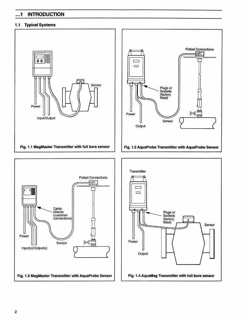
1 INTRODUCTION
1 INTRODUCTION The cable supplied with your MagMasterflowmeter may not be as described in Book 1 or Book 3 ELECTRICAL INSTRUCTIONS. (Cable Part Numbers are printedembossed on the cable sheath)
The alternative cables are as follows:
STT 3200/3400 Standard 4-Core Cable as used in IEC installation practice.
STT 3300 Armoured 4-Core Cable as used in IEC installation practice.
STT3350 Standard 6-Core Cable as used in North American installation practice.
and are as described in this supplement.
1

MAGMASTER INTERCONNECTION CABLE Solution for installations that show the following alarms.
• Alm Coil • Alm Mtsnsr
INTERCONNECTING CABLE MUST BE INSTALLED AS SHOWN
Signal Converter
Flow Tube
Wiring From Mag Sensor Note: Ensure that NONE of the cores or screens are able to short to other cores or any metalwork. ENSURE black antimicrophonic layer is removed from the inner pink and blue wires. ! See Manual for further details C WAAB0085-1
Not Used

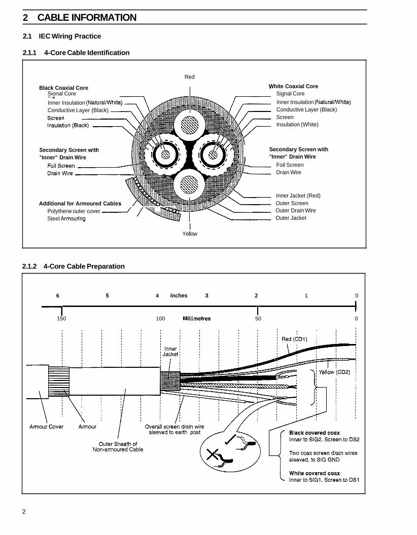
2 CABLE INFORMATION
2.1 IEC Wiring Practice
2.1.1 4-Core Cable Identification
- v
Inner Insulation (NaturalWhite) Conductive Layer (Black)
Secondary Screen w "Inner" Drain Wire
Additional for Armoured Cables
Red
White Coaxial Core Black Coaxial Core Sional Core Signal Core
Inner Insulation (NaturalWhite) Conductive Layer (Black) Screen Insulation (White)
Secondary Screen with "Inner" Drain Wire
Foil Screen Drain Wire
Inner Jacket (Red) Outer Screen Outer Drain Wire Outer Jacket
Polythene outer cover 2 1 Steel Armouring
I Yellow
2.1.2 4-Core Cable Preparation
6 5 4 Inches 3 2 1 0
150 100 Millimetres 50 0
2

. . .2 CABLE INFORMATION
2.2 North American Wiring Practice
2.2.1 6-Core Cable Identification
Grey Coaxial CoreMlires
Inner Insulation (N Conductive Layer Conductive Layer (Black)
White Coaxial Coremires Signal Coremires Inner Insulation (Naturalmhite)
Screen Insulation (White) Foil Screen
Red
Screen Outer Drain Wire Outer Jacket
2.2.2 6-Core Cable Preparation
i
0 5 4 Inches 3 2 1
I I I I I I I I I I I I I I I I I I I
100 Millimetres 50
Outer Insulation
DS2
DS1
a
Overall screen drain wire to ESCRN Length for
Probe Head
UIJ
0
f Length for Transmitter
3

3 CABLE CONNECTIONS
>
Remove any exposed black conductive layer from under coaxial screens. Make connections only as shown. Sleeve all bare wiring. Twist RED and YELLOW cores lightly together. Twist WHITE and BLACK coaxial cables lightly together. Maintain Environmental Protection at all times.
~ Conduit connections must provide cable entry sealing. J
. Outer Screen
Refer to ENVIRONMENTAL PROTECTION (BOOK 3). Internal appearance of Terminal Box may vary from that shown.
Red
Yellow
Two Inner Drain Wires (Sleeved)
White I Coaxial I. Inner
Inner Black
3.1.2 North American Wiring Practice - General Locations and CSA-Hazardous (Non-incendive electrodes). For all other Hazardous Area Versions see Book 1.
Red
Yellow
4 r , I
Violet
Blue
Pink
Screen
Coaxial
Grey Coaxial
Outer Screen (Sleeved)
/
GreenRellow (Ground)

... 3 CABLE CONNECTIONS
3.2 Transmitter Sensor Cable Connections (Remote Transmitter Only)
-A Caution. Remove any exposed black conductive layer from the inner insulation of both coaxial cables. Substitute sensor cable of any kind is not acceptable. Do not make connections except as shown. Twist cable pairs together as shown. Sleeve ALL bare wires. Sensor cable may only be joined using company supplied junction box - available separately.
3.2.1 IEC Wiring Practice
Yellow
Drive Connections
2 Drain wires from coaxial outer screens (SIG GND) (sleeve as illustrated)
J
Cable Screen Connections Outer Screen (ESCRN)
3.2.2 North American Wiring Practice
Drive Connections
GND Connec Greenflellow
Cable Screen Connections Drain Wire (ESCRN)
5


UK
ABB LimitedOldends Lane, StonehouseGloucestershire. GL10 3TA
Tel. +44 (0) 1453 826 661FAX: +44 (0) 1453 829 671
USA
ABB Inc.125 East County Line RoadWarminster, PA 18974-4995
Tel. +1 215 674 6000FAX: +1 215 674 7183
ABB (www.abb.com) is a leader in power and automationtechnologies that enable utility and industry customers toimprove performance while lowering environmentalimpact. The ABB Group of companies operates in around100 countries and employs about 105,000 people.
www.abb.com/instrumentation
IM/M
AG
MA
S Is
sue
8The Company’s policy is one of continuous product improvementand the right is reserved to modify the information containedherein without notice.
Printed in USA
© ABB 2010 (2.10)