book 1 “radar basics”
TRANSCRIPT
Radartutorial (www.radartutorial.eu)
1
Radartutorial Book 1 “Radar Basics”
(Revision from 20.12.2009)
This educational endowment is a printable summary of the first chapter of the internet representation “Radar Basics”, containing a lecture on the principles of radar technology.
Table of Contents:
BOOK 1 “RADAR BASICS” ........................................................................................................................... 1
Learning Objectives .................................................................................................................................... 2 Preamble ..................................................................................................................................................... 2 Basic Principle of Operation ....................................................................................................................... 2
HISTORICAL OVERVIEW ............................................................................................................................ 3
RADAR BASIC PRINCIPLES ........................................................................................................................ 4
Signal Routing ............................................................................................................................................. 5 Signal Timing .............................................................................................................................................. 5 Ranging ....................................................................................................................................................... 6
Maximum Unambiguous Range .............................................................................................................. 6 Radar Waveforms Minimum Range ........................................................................................................ 7 Slant Range.............................................................................................................................................. 7
Direction determination .............................................................................................................................. 7 Bearing .................................................................................................................................................... 7 Elevation Angle ....................................................................................................................................... 8
Height .......................................................................................................................................................... 8 Accuracy ...................................................................................................................................................... 9 Radar Resolution ......................................................................................................................................... 9
Angular Resolution .................................................................................................................................. 9 Range Resolution .................................................................................................................................. 10 Resolution Cell ...................................................................................................................................... 10
Theoretical Maximum Range Equation ..................................................................................................... 11 Antenna Gain ......................................................................................................................................... 11 Antenna Aperture .................................................................................................................................. 12 Radar Cross Section .............................................................................................................................. 12 Free-space Path Loss ............................................................................................................................. 13 External and Internal Losses ................................................................................................................. 13 Converting the Equation ........................................................................................................................ 14 Transmitters Power ................................................................................................................................ 14 MDS- Echo ............................................................................................................................................ 15 Noise ...................................................................................................................................................... 15 Radar Range Equation (Example given) ............................................................................................... 16
False Alarm Rate ....................................................................................................................................... 16 Probability of Detection ............................................................................................................................ 16 Frequency-diversity Radar ........................................................................................................................ 17
Radartutorial (www.radartutorial.eu)
2
Learning Objectives
The learning objectives are a preview of the information you are expected to learn in this chapter. This first chapter of the Radartutorial deals with mathematically basics of Radar Technology. This chapter provides the basis for understanding the subsequent chapter on the specific sub system modules. It is intended to give a background in radar theory, including radar principles, propagation, radar signals, resolution and the radar equation. At the end of this chapter, students should understand the fundamentals of radar and recognize the key performance parameters associated with primary radar specifications.
The student should be able to:
explain the basic operation of a pulse radar system;
define range, bearing, and altitude as they relate to a radar system;
discuss how pulse width, peak power, and beam width affect radar performance;
describe the factors that contribute to or deteriorate from radar resolution;
know the advantages of a frequency diversity radar;
using a block diagram, describe the basic function, principles of operation, and interrelationships of the basic units of a radar system.
Preamble
The basic principle of operation of primary radar is simple to understand. However, the theory can be quite complex. An understanding of the theory is essential in order to be able to specify and operate primary radar systems correctly. The implementation and operation of primary radars systems involve a wide range of disciplines such as building works, heavy mechanical and electrical engineering, high power microwave engineering, and advanced high speed signal and data processing techniques. Some laws of nature have a greater importance here.
Basic Principle of Operation
Radar measurement of range, or distance, is made possible because of the properties of radiated electromagnetic energy:
This energy normally travels through space in a straight line, at a constant speed, and will vary only slightly because of atmospheric and weather conditions.
(The effects atmosphere and weather have on this energy will be discussed later; however, for this discussion on determining range, these effects will be temporarily ignored.)
Electromagnetic energy travels through air at approximately the speed of light,
300,000 kilometers per second or
186,000 statute miles per second or
162,000 nautical miles per second.
Reflection of electromagnetic waves
The electromagnetic waves are reflected if they meet an electrically leading surface. If these reflected waves are received again at the place of their origin, then that means an obstacle is in the propagation direction.
These principles can basically be implemented in a radar system, and allow the determination of the distance, the direction and the height of the reflecting object.

Radartutorial (www.radartutorial.eu)
3
Figure 2: Cover of the patent script
Figure 1: “Würzburg Riese”, World War II radar
produced in 1940 by Telefunken (Germany)
Historical Overview
Neither a single nation nor a single person is able to say, that he (or it) is the inventor of the radar method. One must look at the “Radar” than an accumulation of many developments and improvements earlier, which scientists of several nations parallel made share. There are nevertheless some milestones with the discovery of important basic knowledge and important inventions:
1865 The English physicist James Clerk Maxwell developed his electro-magnetic light theory (Description of the electro-magnetic waves and her propagation)
1886 The German physicist Heinrich Rudolf Hertz discovers the electro-magnetic waves and proves the theory of Maxwell with that.
1904 The German high frequency engineer Christian Hülsmeyer invents the “Telemobiloskop” to the traffic supervision on the water. He measures the running time of electro-magnetic waves to a metal object (ship) and back. A calculation of the distance is thus possible. This is the first practical radar test. Hülsmeyer registers his invention to the patent in Germany and in the United Kingdom.
1917 The French engineer Lucien Lévy invents the super-heterodyne receiver. He uses as first the denomination “Intermediate Frequency”, and alludes the possibility of double heterodyning.
1921 The invention of the Magnetron as an efficient transmitting tube by the US-American physicist Albert Wallace Hull
1922 The American electrical engineers Albert H. Taylor and Leo C. Young of the Naval Research Laboratory (USA) locate a wooden ship for the first time.
1930 Lawrence A. Hyland (also of the Naval Research Laboratory), locates an aircraft for the first time.
1931 A ship is equipped with radar. As antennae are used parabolic dishes with horn radiators.
1936 The development of the Klystron by the technicians George F. Metcalf and William C. Hahn, both from General Electric. This will be an important component in radar units as an amplifier or an oscillator tube.
1940 Different radar equipments are developed in the USA, Russia, Germany, France and Japan.
The reasoning to use of electric magnetic waves to the locating of ships has been registered of the engineer of Düsseldorf, Christian Hülsmeyer, already 1904 in Germany and England as a patent. One finds the illustration in the patent specification of a steamer which detects an approaching ship with help of the backscattering. Tests carried out on the Rhine River had in principle yielded the usefulness of this method.
Radartutorial (www.radartutorial.eu)
4
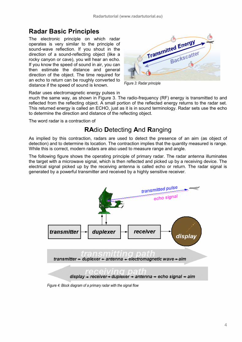
Figure 3: Radar principle
Radar Basic Principles The electronic principle on which radar operates is very similar to the principle of sound-wave reflection. If you shout in the direction of a sound-reflecting object (like a rocky canyon or cave), you will hear an echo. If you know the speed of sound in air, you can then estimate the distance and general direction of the object. The time required for an echo to return can be roughly converted to distance if the speed of sound is known.
Radar uses electromagnetic energy pulses in much the same way, as shown in Figure 3. The radio-frequency (RF) energy is transmitted to and reflected from the reflecting object. A small portion of the reflected energy returns to the radar set. This returned energy is called an ECHO, just as it is in sound terminology. Radar sets use the echo to determine the direction and distance of the reflecting object.
The word radar is a contraction of
RAdio Detecting And Ranging
As implied by this contraction, radars are used to detect the presence of an aim (as object of detection) and to determine its location. The contraction implies that the quantity measured is range. While this is correct, modern radars are also used to measure range and angle.
The following figure shows the operating principle of primary radar. The radar antenna illuminates the target with a microwave signal, which is then reflected and picked up by a receiving device. The electrical signal picked up by the receiving antenna is called echo or return. The radar signal is generated by a powerful transmitter and received by a highly sensitive receiver.
Figure 4: Block diagram of a primary radar with the signal flow

Radartutorial (www.radartutorial.eu)
5
Figure 5: A typical radar time line
Signal Routing
The radar transmitter produces short duration high-power RF- pulses of energy.
The duplexer alternately switches the antenna between the transmitter and receiver so that only one antenna need be used. This switching is necessary because the high-power pulses of the transmitter would destroy the receiver if energy were allowed to enter the receiver.
The antenna transfers the transmitter energy to signals in space with the required distribution and efficiency. This process is applied in an identical way on reception.
The transmitted pulses are radiated into space by the antenna as an electromagnetic wave. This wave travels in a straight line with a constant velocity and will be reflected by an aim.
The antenna receives the back scattered echo signals.
During reception the duplexer lead the weakly echo signals to the receiver.
The hypersensitive receiver amplifies and demodulates the received RF-signals. The receiver provides video signals on the output.
The indicator should present to the observer a continuous, easily understandable, graphic picture of the relative position of radar targets.
All targets produce a diffuse reflection i.e. it is reflected in a wide number of directions. The reflected signal is also called scattering. Backscatter is the term given to reflections in the opposite direction to the incident rays.
Radar signals can be displayed on the traditional plan position indicator (PPI) or other more advanced radar display systems. A PPI has a rotating vector with the radar at the origin, which indicates the pointing direction of the antenna and hence the bearing of targets. It shows a map-like picture of the area covered by the radar beam.
Signal Timing
Most functions of a radar set are time-dependent. Time synchronization between the transmitter and receiver of a radar set is required for range measurement. Radar systems radiate each pulse during
transmit time (or Pulse Width τ), wait for returning echoes during listening or rest time, and then
radiate the next pulse, as shown in Figure 5.
A so called synchronizer coordinates the timing for range determination and supplies the synchronizing signals for the radar. It sent simultaneously signals to the transmitter, which sends a new pulse, and to the indicator, and other associated circuits.
The time between the beginning of one pulse and the start of the next pulse is called pulse-repetition time (PRT) and is equal to the reciprocal of PRF as follows:
1PRT
PRF
The Pulse Repetition Frequency (PRF) of the radar system is the number of pulses that are transmitted per second. The frequency of pulse transmission affects the maximum range that can be displayed, as we shall see later.
transmitted pulse
echo pulse
transmit time or Pulse Width τ
receiving time rest time
Pulse Repetition Time (PRT) or Pulse Repetition Period (PRP)
Radartutorial (www.radartutorial.eu)
6
Ranging
The distance of the aim is determined from the running time of the high-frequency transmitted signal and the propagation c0. The actual range of a target from the radar is known as slant range. Slant range is the line of sight distance between the radar and the object illuminated. While ground range is the horizontal distance between the emitter and its target and its calculation requires knowledge of the target's elevation. Since the waves travel to a target and back, the round trip time is divided by two in order to obtain the time the wave took to reach the target. Therefore the following formula arises for the slant range:
0
2
delayt cR
If the respective running time tdelay is known, then the distance R between a target and the radar set can be calculated by using this equation.
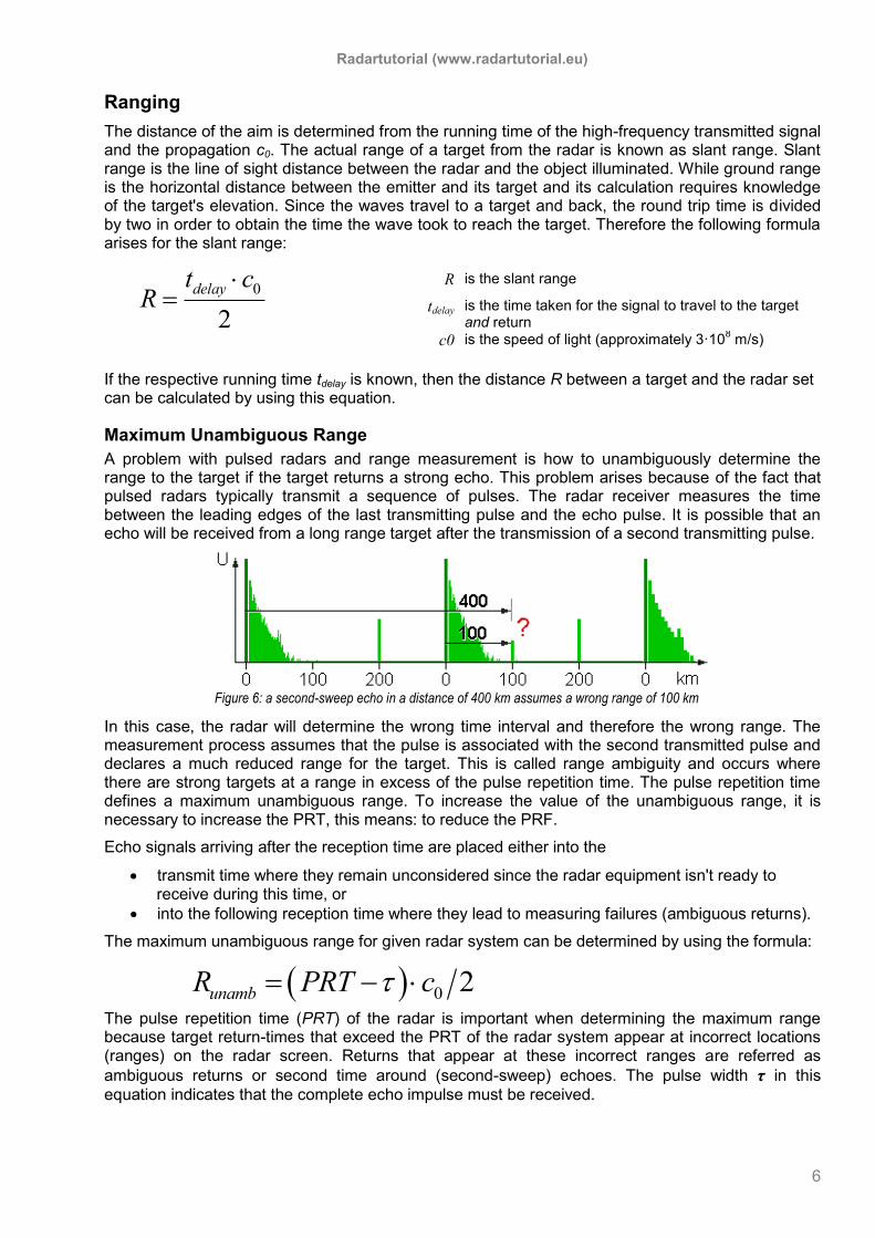
Maximum Unambiguous Range
A problem with pulsed radars and range measurement is how to unambiguously determine the range to the target if the target returns a strong echo. This problem arises because of the fact that pulsed radars typically transmit a sequence of pulses. The radar receiver measures the time between the leading edges of the last transmitting pulse and the echo pulse. It is possible that an echo will be received from a long range target after the transmission of a second transmitting pulse.
In this case, the radar will determine the wrong time interval and therefore the wrong range. The measurement process assumes that the pulse is associated with the second transmitted pulse and declares a much reduced range for the target. This is called range ambiguity and occurs where there are strong targets at a range in excess of the pulse repetition time. The pulse repetition time defines a maximum unambiguous range. To increase the value of the unambiguous range, it is necessary to increase the PRT, this means: to reduce the PRF.
Echo signals arriving after the reception time are placed either into the
transmit time where they remain unconsidered since the radar equipment isn't ready to receive during this time, or
into the following reception time where they lead to measuring failures (ambiguous returns).
The maximum unambiguous range for given radar system can be determined by using the formula:
0 2unambR PRT c
The pulse repetition time (PRT) of the radar is important when determining the maximum range because target return-times that exceed the PRT of the radar system appear at incorrect locations (ranges) on the radar screen. Returns that appear at these incorrect ranges are referred as
ambiguous returns or second time around (second-sweep) echoes. The pulse width τ in this
equation indicates that the complete echo impulse must be received.
R is the slant range
tdelay is the time taken for the signal to travel to the target and return
c0 is the speed of light (approximately 3·108 m/s)
Figure 6: a second-sweep echo in a distance of 400 km assumes a wrong range of 100 km

Radartutorial (www.radartutorial.eu)
7
Figure 8: True Bearing
Figure 7: Different height causes a different slant range
Radar Waveforms Minimum Range
The minimum detectable range (or blind distance) is also a consideration. When the leading edge of the echo pulse falls inside the transmitting pulse, it is impossible to determine the “round trip time”,
which means that the distance cannot be measured. The minimum detectable range Rmin depends
on the transmitters pulse with τ, and the recovery time trecovery of the duplexer.
cov 0
2
re ery
min
t cR
The receiver does not listen during the transmitting pulse, because it needs to be disconnected from the transmitter during transmission to avoid damage. In that case, the echo pulse comes from a very close target. Targets at a range equivalent to the pulse width from the radar are not detected. A typical value of 1 µs for the pulse width of short range radar corresponds to a minimum range of about 150 m, which is generally acceptable. However, radars with a longer pulse width suffer a relatively large minimum range, notably pulse compression radars, which can use pulse lengths of
the order of tens or even hundreds of microseconds. Typical pulse width τ for
Air-defense radar: up to 800 µs (Rmin = 120 km !)
ATC air surveillance radar: 1.5 µs (Rmin = 250 m)
surface movement radar: 100 ns (Rmin = 25 m)
Slant Range
Cause by the fact that the radar unit measures a slope range, the radar measures different ranges of two airplanes, which exactly one above the other flies (therefore having the same topographical distance to the radar unit exactly). This false measurement could be corrected by software, or module in modern radar sets with digital signal processing. These software modules then must also especially be adapted on the geographical coordinates of the radar site, however. The calculation is very complicated and also requires some weather data to the correction.
Direction determination
Bearing
The direction to the target is determined by the directivity of the antenna. Directivity, sometimes known as the directive gain, is the ability of the antenna to concentrate the transmitted energy in a particular direction. An antenna with high directivity is also called a directive antenna. By measuring the direction in which the antenna is pointing when the echo is received, both the azimuth and elevation angles from the radar to the object or target can be determined. The accuracy of angular measurement is determined by the directivity, which is a function of the size of the antenna.
Radartutorial (www.radartutorial.eu)
8
Figure 9: Definition of elevation angle
Figure 10: Altitude vs. Height
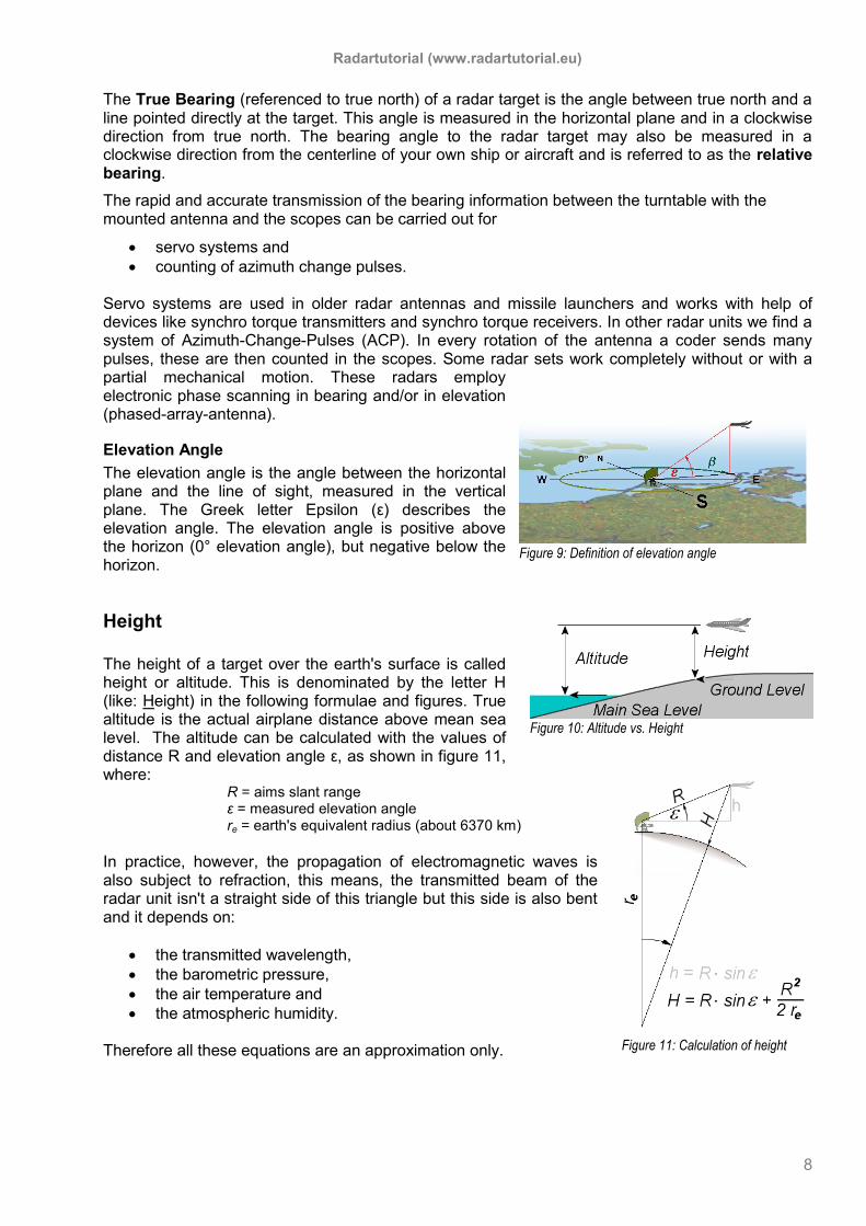
The True Bearing (referenced to true north) of a radar target is the angle between true north and a line pointed directly at the target. This angle is measured in the horizontal plane and in a clockwise direction from true north. The bearing angle to the radar target may also be measured in a clockwise direction from the centerline of your own ship or aircraft and is referred to as the relative bearing.
The rapid and accurate transmission of the bearing information between the turntable with the mounted antenna and the scopes can be carried out for
servo systems and
counting of azimuth change pulses. Servo systems are used in older radar antennas and missile launchers and works with help of devices like synchro torque transmitters and synchro torque receivers. In other radar units we find a system of Azimuth-Change-Pulses (ACP). In every rotation of the antenna a coder sends many pulses, these are then counted in the scopes. Some radar sets work completely without or with a partial mechanical motion. These radars employ electronic phase scanning in bearing and/or in elevation (phased-array-antenna).
Elevation Angle
The elevation angle is the angle between the horizontal plane and the line of sight, measured in the vertical plane. The Greek letter Epsilon (ε) describes the elevation angle. The elevation angle is positive above the horizon (0° elevation angle), but negative below the horizon.
Height
The height of a target over the earth's surface is called height or altitude. This is denominated by the letter H (like: Height) in the following formulae and figures. True altitude is the actual airplane distance above mean sea level. The altitude can be calculated with the values of distance R and elevation angle ε, as shown in figure 11, where:
R = aims slant range ε = measured elevation angle re = earth's equivalent radius (about 6370 km)
In practice, however, the propagation of electromagnetic waves is also subject to refraction, this means, the transmitted beam of the radar unit isn't a straight side of this triangle but this side is also bent and it depends on:
the transmitted wavelength,
the barometric pressure,
the air temperature and
the atmospheric humidity. Therefore all these equations are an approximation only.
Figure 11: Calculation of height
Radartutorial (www.radartutorial.eu)
9
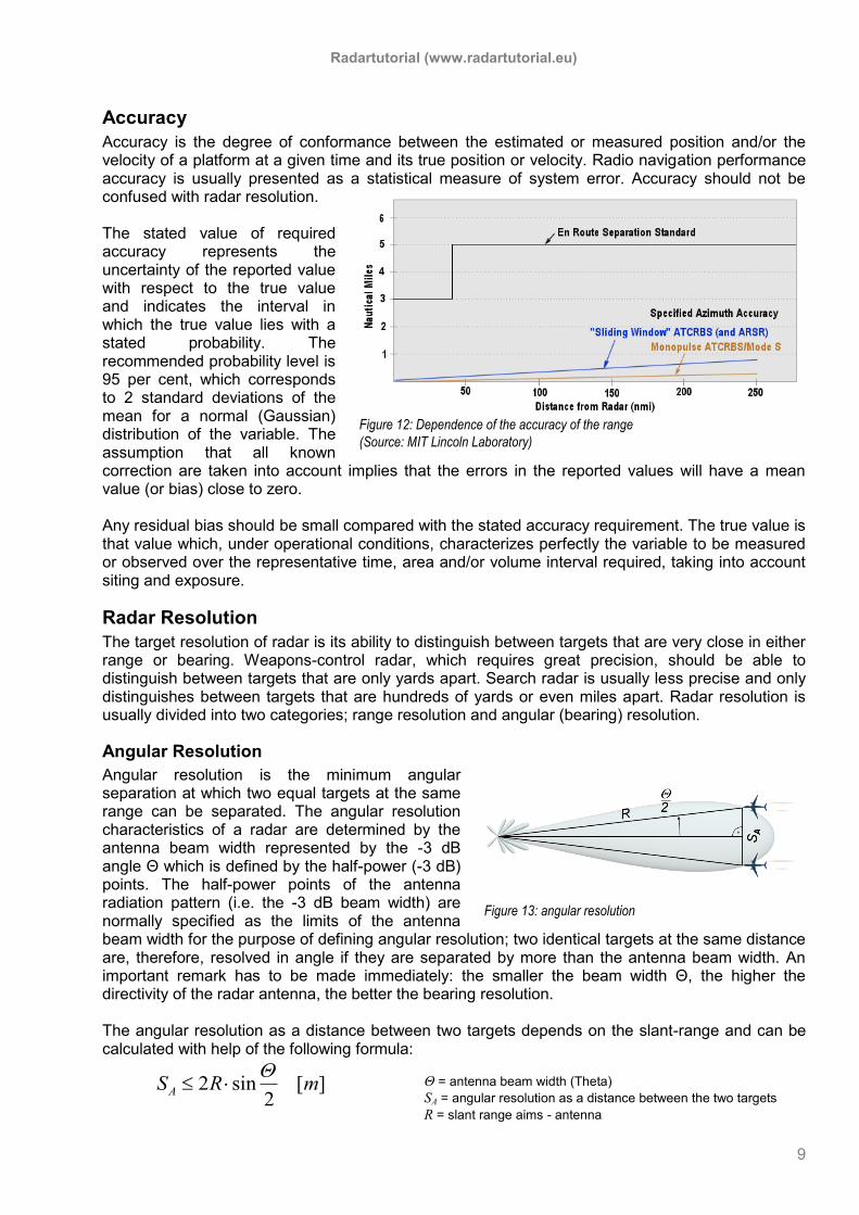
Accuracy
Accuracy is the degree of conformance between the estimated or measured position and/or the velocity of a platform at a given time and its true position or velocity. Radio navigation performance accuracy is usually presented as a statistical measure of system error. Accuracy should not be confused with radar resolution. The stated value of required accuracy represents the uncertainty of the reported value with respect to the true value and indicates the interval in which the true value lies with a stated probability. The recommended probability level is 95 per cent, which corresponds to 2 standard deviations of the mean for a normal (Gaussian) distribution of the variable. The assumption that all known correction are taken into account implies that the errors in the reported values will have a mean value (or bias) close to zero. Any residual bias should be small compared with the stated accuracy requirement. The true value is that value which, under operational conditions, characterizes perfectly the variable to be measured or observed over the representative time, area and/or volume interval required, taking into account siting and exposure.
Radar Resolution
The target resolution of radar is its ability to distinguish between targets that are very close in either range or bearing. Weapons-control radar, which requires great precision, should be able to distinguish between targets that are only yards apart. Search radar is usually less precise and only distinguishes between targets that are hundreds of yards or even miles apart. Radar resolution is usually divided into two categories; range resolution and angular (bearing) resolution.
Angular Resolution
Angular resolution is the minimum angular separation at which two equal targets at the same range can be separated. The angular resolution characteristics of a radar are determined by the antenna beam width represented by the -3 dB angle Θ which is defined by the half-power (-3 dB) points. The half-power points of the antenna radiation pattern (i.e. the -3 dB beam width) are normally specified as the limits of the antenna beam width for the purpose of defining angular resolution; two identical targets at the same distance are, therefore, resolved in angle if they are separated by more than the antenna beam width. An important remark has to be made immediately: the smaller the beam width Θ, the higher the directivity of the radar antenna, the better the bearing resolution. The angular resolution as a distance between two targets depends on the slant-range and can be calculated with help of the following formula:
2 sin [ ]2
AS R m
Figure 12: Dependence of the accuracy of the range
(Source: MIT Lincoln Laboratory)
Figure 13: angular resolution
Θ = antenna beam width (Theta)
SA = angular resolution as a distance between the two targets
R = slant range aims - antenna
Radartutorial (www.radartutorial.eu)
10
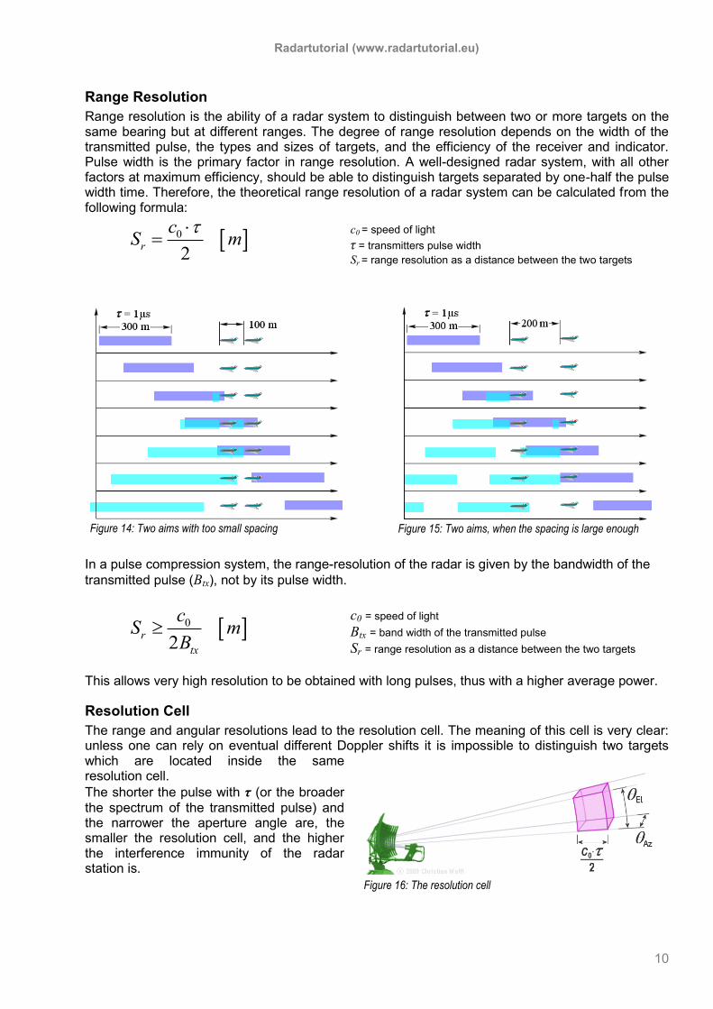
Range Resolution
Range resolution is the ability of a radar system to distinguish between two or more targets on the same bearing but at different ranges. The degree of range resolution depends on the width of the transmitted pulse, the types and sizes of targets, and the efficiency of the receiver and indicator. Pulse width is the primary factor in range resolution. A well-designed radar system, with all other factors at maximum efficiency, should be able to distinguish targets separated by one-half the pulse width time. Therefore, the theoretical range resolution of a radar system can be calculated from the following formula:
0
2r
cS m
In a pulse compression system, the range-resolution of the radar is given by the bandwidth of the
transmitted pulse (Btx), not by its pulse width.
0
2r
tx
cS m
B
This allows very high resolution to be obtained with long pulses, thus with a higher average power.
Resolution Cell
The range and angular resolutions lead to the resolution cell. The meaning of this cell is very clear: unless one can rely on eventual different Doppler shifts it is impossible to distinguish two targets which are located inside the same resolution cell.
The shorter the pulse with τ (or the broader
the spectrum of the transmitted pulse) and the narrower the aperture angle are, the smaller the resolution cell, and the higher the interference immunity of the radar station is.
c0 = speed of light
τ = transmitters pulse width
Sr = range resolution as a distance between the two targets
Figure 15: Two aims, when the spacing is large enough
Figure 14: Two aims with too small spacing
c0 = speed of light
Btx = band width of the transmitted pulse
Sr = range resolution as a distance between the two targets
Figure 16: The resolution cell
Radartutorial (www.radartutorial.eu)
11
Figure 16: Pattern of a highly directional antenna
compared with a ball-shaped isotropic pattern
Theoretical Maximum Range Equation
The radar equation represents the physical dependences of the transmit power, that is the wave propagation up to the receiving of the echo-signals. Furthermore one can assess the performance of the radar with the radar equation. The received energy is an extremely small part of the transmitted energy. How small is it?
2 2
3 44
trx tx
s
GP P
R L
The radar equation relates the important parameters affecting the received signal of radar. The derivation is explained in many texts1. Now we want to study, what kinds of factors are expressed in this radar equation.
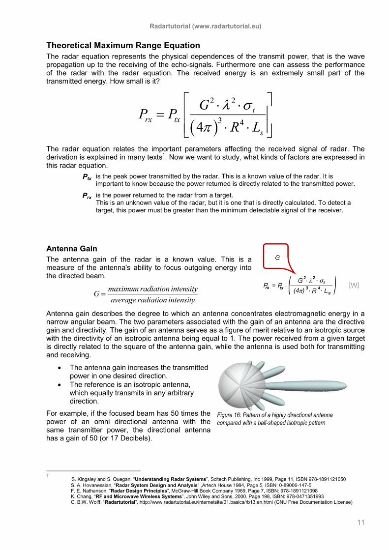
Antenna Gain
The antenna gain of the radar is a known value. This is a measure of the antenna's ability to focus outgoing energy into the directed beam.
maximum radiation intensity
Gaverage radiation intensity
Antenna gain describes the degree to which an antenna concentrates electromagnetic energy in a narrow angular beam. The two parameters associated with the gain of an antenna are the directive gain and directivity. The gain of an antenna serves as a figure of merit relative to an isotropic source with the directivity of an isotropic antenna being equal to 1. The power received from a given target is directly related to the square of the antenna gain, while the antenna is used both for transmitting and receiving.
The antenna gain increases the transmitted power in one desired direction.
The reference is an isotropic antenna, which equally transmits in any arbitrary direction.
For example, if the focused beam has 50 times the power of an omni directional antenna with the same transmitter power, the directional antenna has a gain of 50 (or 17 Decibels).
1 S. Kingsley and S. Quegan, “Understanding Radar Systems”, Scitech Publishing, Inc 1999, Page 11, ISBN 978-1891121050
S. A. Hovanessian, “Radar System Design and Analysis” ,Artech House 1984, Page 5, ISBN: 0-89006-147-5 F. E. Nathanson, “Radar Design Principles”, McGraw-Hill Book Company 1969, Page 7, ISBN: 978-1891121098 K. Chang, “RF and Microwave Wireless Systems”, John Wiley and Sons, 2000. Page 198, ISBN: 978-0471351993 C. B.W. Wolff, “Radartutorial”, http://www.radartutorial.eu/internetsite/01.basics/rb13.en.html (GNU Free Documentation License)
Ptx is the peak power transmitted by the radar. This is a known value of the radar. It is important to know because the power returned is directly related to the transmitted power.
Prx is the power returned to the radar from a target. This is an unknown value of the radar, but it is one that is directly calculated. To detect a target, this power must be greater than the minimum detectable signal of the receiver.
Radartutorial (www.radartutorial.eu)
12
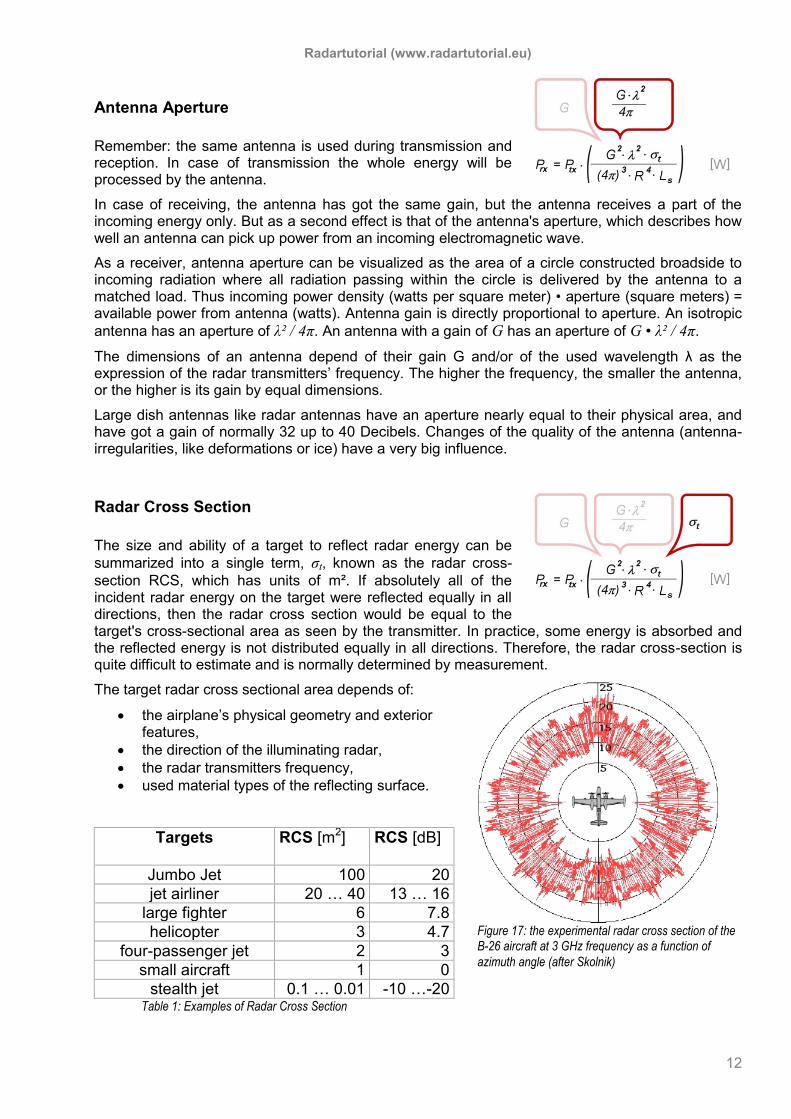
Figure 17: the experimental radar cross section of the B-26 aircraft at 3 GHz frequency as a function of
azimuth angle (after Skolnik)
Antenna Aperture
Remember: the same antenna is used during transmission and reception. In case of transmission the whole energy will be processed by the antenna.
In case of receiving, the antenna has got the same gain, but the antenna receives a part of the incoming energy only. But as a second effect is that of the antenna's aperture, which describes how well an antenna can pick up power from an incoming electromagnetic wave.
As a receiver, antenna aperture can be visualized as the area of a circle constructed broadside to incoming radiation where all radiation passing within the circle is delivered by the antenna to a matched load. Thus incoming power density (watts per square meter) • aperture (square meters) = available power from antenna (watts). Antenna gain is directly proportional to aperture. An isotropic
antenna has an aperture of λ² / 4π. An antenna with a gain of G has an aperture of G • λ² / 4π.
The dimensions of an antenna depend of their gain G and/or of the used wavelength λ as the expression of the radar transmitters’ frequency. The higher the frequency, the smaller the antenna, or the higher is its gain by equal dimensions.
Large dish antennas like radar antennas have an aperture nearly equal to their physical area, and have got a gain of normally 32 up to 40 Decibels. Changes of the quality of the antenna (antenna-irregularities, like deformations or ice) have a very big influence.
Radar Cross Section
The size and ability of a target to reflect radar energy can be
summarized into a single term, σt, known as the radar cross-
section RCS, which has units of m². If absolutely all of the incident radar energy on the target were reflected equally in all directions, then the radar cross section would be equal to the target's cross-sectional area as seen by the transmitter. In practice, some energy is absorbed and the reflected energy is not distributed equally in all directions. Therefore, the radar cross-section is quite difficult to estimate and is normally determined by measurement.
The target radar cross sectional area depends of:
the airplane’s physical geometry and exterior features,
the direction of the illuminating radar,
the radar transmitters frequency,
used material types of the reflecting surface.
Targets
RCS [m2]
RCS [dB]
Jumbo Jet 100 20
jet airliner 20 … 40 13 … 16
large fighter 6 7.8
helicopter 3 4.7
four-passenger jet 2 3
small aircraft 1 0
stealth jet 0.1 … 0.01 -10 …-20 Table 1: Examples of Radar Cross Section
Radartutorial (www.radartutorial.eu)
13
Figure 18: Non-directional power density diminishes as geometric spreading of the
beam.
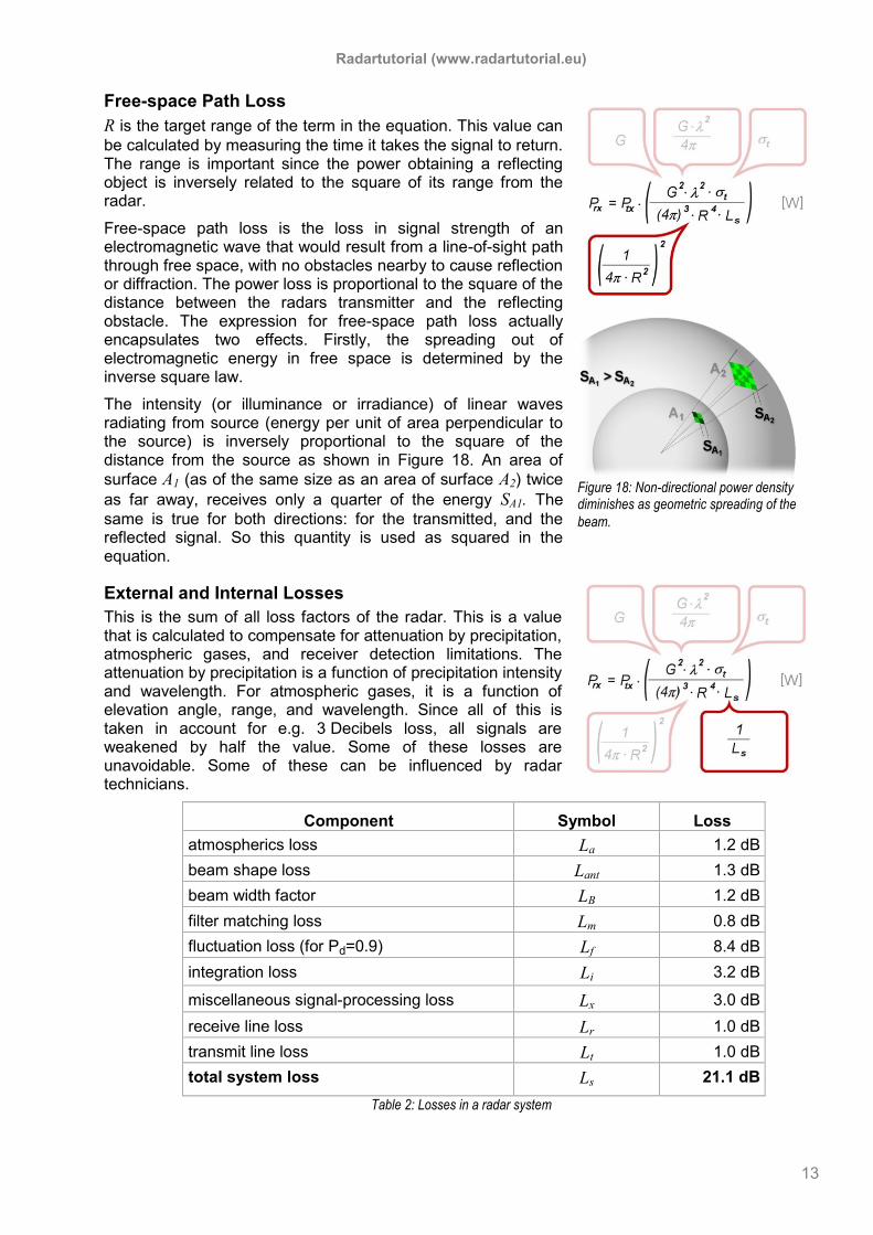
Free-space Path Loss
R is the target range of the term in the equation. This value can
be calculated by measuring the time it takes the signal to return. The range is important since the power obtaining a reflecting object is inversely related to the square of its range from the radar.
Free-space path loss is the loss in signal strength of an electromagnetic wave that would result from a line-of-sight path through free space, with no obstacles nearby to cause reflection or diffraction. The power loss is proportional to the square of the distance between the radars transmitter and the reflecting obstacle. The expression for free-space path loss actually encapsulates two effects. Firstly, the spreading out of electromagnetic energy in free space is determined by the inverse square law.
The intensity (or illuminance or irradiance) of linear waves radiating from source (energy per unit of area perpendicular to the source) is inversely proportional to the square of the distance from the source as shown in Figure 18. An area of
surface A1 (as of the same size as an area of surface A2) twice
as far away, receives only a quarter of the energy SA1. The
same is true for both directions: for the transmitted, and the reflected signal. So this quantity is used as squared in the equation.
External and Internal Losses
This is the sum of all loss factors of the radar. This is a value that is calculated to compensate for attenuation by precipitation, atmospheric gases, and receiver detection limitations. The attenuation by precipitation is a function of precipitation intensity and wavelength. For atmospheric gases, it is a function of elevation angle, range, and wavelength. Since all of this is taken in account for e.g. 3 Decibels loss, all signals are weakened by half the value. Some of these losses are unavoidable. Some of these can be influenced by radar technicians.
Component Symbol Loss
atmospherics loss La 1.2 dB
beam shape loss Lant 1.3 dB
beam width factor LB 1.2 dB
filter matching loss Lm 0.8 dB
fluctuation loss (for Pd=0.9) Lf 8.4 dB
integration loss Li 3.2 dB
miscellaneous signal-processing loss Lx 3.0 dB
receive line loss Lr 1.0 dB
transmit line loss Lt 1.0 dB
total system loss Ls 21.1 dB
Table 2: Losses in a radar system
Radartutorial (www.radartutorial.eu)
14
2 2 4
3 4
2 24 4
3
2 2
4 3
4
4
4
trx tx
rxs
ttx
rx s
tx t
rx s
G RP P
PR L
GR P
P L
P GR
P L
max
2 2
4 34 MDS
tx t
s
P GR
P L
Converting the Equation
This radar equation can be transformed to see the factors of influence of some technical characteristics of given radar set, and to determine its theoretical maximum range. Perhaps the most important feature of this converted equation is the fourth-root dependence.
The smallest signal that can be detected by the radar is called Minimum Discernible Signal. Smaller powers
than this PMDS aren't usable since they are lost in the
noise of the receiver and its environment. The
minimum power is detect at the maximum range Rmax
as seen from the equation. So the theoretically maximum range of given radar set can be calculated.
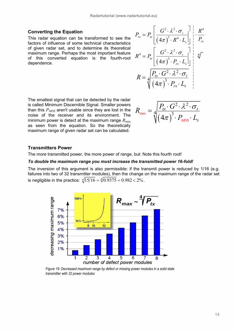
Transmitters Power
The more transmitted power, the more power of range, but: Note this fourth root!
To double the maximum range you must increase the transmitted power 16-fold!
The inversion of this argument is also permissible: if the transmit power is reduced by 1/16 (e.g. failures into two of 32 transmitter modules), then the change on the maximum range of the radar set
is negligible in the practice: 44 15 16 0.9375 0.982 2% .
Figure 19: Decreased maximum range by defect or missing power modules in a solid state
transmitter with 32 power modules

Radartutorial (www.radartutorial.eu)
15
max
2 2
4 34 MDS
tx t
s
P GR
P L
MDS- Echo
The minimum discernible signal is defined as the useful echo power at the reception antenna, which gives on the screen a discernible blip. The minimum discernible signal at the receiver input-jack leads to the maximum range of the radar; all other nominal variables are considered as constant. A reduction of the minimal received power of the receiver gets an increase of the maximum range. For every receiver there is a certain receiving power as of which the receiver can work at all. This smallest workable received power is frequently often called MDS - Minimum Discernible Signal or Minimum Detectable Signal in radar technology. Typical radar values of the MDS echo lie in the range of -104 dBm to -113 dBm.
Noise
The value of the MDS echo depends on the Signal-to-Noise-Ratio, defined as the ratio of the signal energy to the noise energy. All radars, as with all electronic equipment, must operate in the presence of noise. The main source of noise is termed thermal noise and is due to agitation of electrons caused by heat. The noise can arise from
received atmospheric or cosmic noise
receiver noise - generated internally in the radar receiver.
The overall receiver sensitivity is directly related to the noise figure of the radar receiver. It becomes clear, that a low noise figure receiver is accomplished by a good design in the very front-end components. An aspect to a very low noise figure receiver is achieved through minimizing the noise factor of the very first block. This component usual is characterized by a low noise figure with high gain. This is the reason for the often used denomination, low noise preamplifier (LNA).
Figure 21: E.g. a Didactical Primary Radar: If the noise figure were the only issue one was trying to address in the design of a receiver,
then placing as much gain as close to the beginning of the receive chain as possible is desired.
Figure 20: Signal-Noise-Ratio 3dB shown on an A-Scope
Radartutorial (www.radartutorial.eu)
16
Radar Range Equation (Example given)
One of the important uses of the radar range equation is in the determination of detection range, or the maximum range at which a target has a high probability of being detected by the radar.
Table 3: Example of a real radar set
If we substitute the metric values from the upper table into the radar range equation we get:
6 2 2
3 15
2 2 4
4max 3
1 10 1900 0.11 14
4 5 10 128.8
W m
W76.5 km
4
tx t
MDS s
P GR
P L
The result expressed in nautical miles is 41.3 NM.
False Alarm Rate
A false alarm is “an erroneous radar target detection decision caused by noise or other interfering signals exceeding the detection threshold”. In general, it is an indication of the presence of a radar target when there is no valid target. The False Alarm Rate (FAR) is calculated using the following formula:
false targets per PRT
FARnumber of rangecells
False alarms are generated when thermal noise exceeds a pre-set threshold level, by the presence of spurious signals (either internal to the radar receiver or from sources external to the radar), or by equipment malfunction. A false alarm may be manifested as a momentary blip on a cathode ray tube (CRT) display, a digital signal processor output, an audio signal, or by all of these means. If the detection threshold is set too high, there will be very few false alarms, but the signal-to-noise ratio required will inhibit detection of valid targets. If the threshold is set too low, the large number of false alarms will mask detection of valid targets.
Probability of Detection
The received and demodulated echo signal is processed by threshold logic. This threshold shall be balanced so that as of certain amplitude wanted signals being able to pass and noise will be removed. Since high noise exists in the mixed signal tops which lie in the range of small wanted signals the optimized threshold level shall be a compromise. Wanted signals shall on the one hand reach the indication as of minimal amplitude; on the other hand the false alarm rate may not increase.
100%D
detected targetsP
all possible blibs
The system must detect, with greater than or equal to 80% probability at a defined range, a one square meter radar cross section.
Radar Range Equation Parameter
Metric units Decibels
Radiated Power Ptx 1· 10 6 W 60 dBW
Antenna Gain G 1900 32.8 dB
Transmitters Wavelength λ (at 2,700 MHz) 0.11m
Radar Cross Section σ (e.g. of a small aircraft) 1 m2
MDS echo PMDS 5 · 10 -15 W -113 dBm
Sum of losses (see: Table 2) LS 128.8 21.1 dB
Radartutorial (www.radartutorial.eu)
17
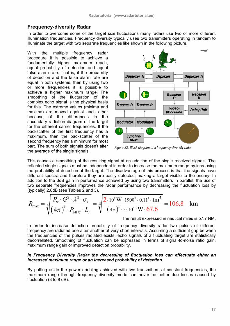
Figure 22: Block diagram of a frequency-diversity radar
Frequency-diversity Radar
In order to overcome some of the target size fluctuations many radars use two or more different illumination frequencies. Frequency diversity typically uses two transmitters operating in tandem to illuminate the target with two separate frequencies like shown in the following picture. With the multiple frequency radar procedure it is possible to achieve a fundamentally higher maximum reach, equal probability of detection and equal false alarm rate. That is, if the probability of detection and the false alarm rate are equal in both systems, then by using two or more frequencies it is possible to achieve a higher maximum range. The smoothing of the fluctuation of the complex echo signal is the physical basis for this. The extreme values (minima and maxima) are moved against each other because of the differences in the secondary radiation diagram of the target for the different carrier frequencies. If the backscatter of the first frequency has a maximum, then the backscatter of the second frequency has a minimum for most part. The sum of both signals doesn’t alter the average of the single signals. This causes a smoothing of the resulting signal at an addition of the single received signals. The reflected single signals must be independent in order to increase the maximum range by increasing the probability of detection of the target. The disadvantage of this process is that the signals have different spectra and therefore they are easily detected, making a target visible to the enemy. In addition to the 3dB gain in performance achieved by using two transmitters in parallel, the use of two separate frequencies improves the radar performance by decreasing the fluctuation loss by (typically) 2.8dB (see Tables 2 and 3).
6 2 2
3 15
2 2 4
4max 3
10 1900 0.11 14
4 5 10
W m
W
2106.8
67km
4 .6
tx t
MDS s
P GR
P L
The result expressed in nautical miles is 57.7 NM.
In order to increase detection probability of frequency diversity radar two pulses of different frequency are radiated one after another at very short intervals. Assuming a sufficient gap between the frequencies of the pulses radiated exists, echo signals of a fluctuating target are statistically decorrellated. Smoothing of fluctuation can be expressed in terms of signal-to-noise ratio gain, maximum range gain or improved detection probability. In Frequency Diversity Radar the decreasing of fluctuation loss can effectuate either an increased maximum range or an increased probability of detection. By putting aside the power doubling achieved with two transmitters at constant frequencies, the maximum range through frequency diversity mode can never be better due losses caused by fluctuation (3 to 8 dB).
Radartutorial (www.radartutorial.eu)
18
Training Questions Please try to answer some of the more frequently asked training questions. The reasonable time to frame the answers is about 30 minutes. You can use pocket calculator, but the chosen here numerical examples are optimized to perform with mental arithmetic.
1. Specify the flow of radar signals from the originating device in given radar set to the users display!
2. Describe the field of functions of a duplexer and state a case on that condition given radar
can work without a duplexer. 3. A frequency-diversity radar with two identically transmitters use one transmitter only.
a. Please calculate the decreasing the range of the radar (without consideration of the
fluctuation loss) according the radar equation. b. How the additional influences of the fluctuation loss affect the radar range
tendentiously?
4. The transmitters pulse width of pulsed radar is 1.5 µs and the duplexers recovery time is 0.5 µs. How far-off the antenna an airplane must be located at the least as to be detecting by the radar?