bombardier global 000-navigation
DESCRIPTION
NAVIGATION TABLE OF CONTENTS CHAPTER 17Page TABLE OF CONTENTS DESCRIPTION General Audio Control Panel Radio Management Unit (RMU) VHF Navigation Receivers NAV 1 (2) Distance Measuring Equipment (DME) Air Traffic Control (ATC) Transponder Traffic Alert and Collision Avoidance System (TCAS) Target/Threat Advisories TCAS Symbology TCAS Modes ATC/TCAS Mode Select TCAS DSPY 1 (2) Select TCAS Mode Select Annunciation TCAS Status Messages Digitized Voice Resolution Advisories TCAS Zoom Window TCAS TraTRANSCRIPT

DESCRIPTION
General 17−10−1
Audio Control Panel 17−10−2
Radio Management Unit (RMU) 17−10−3
VHF Navigation Receivers 17−10−4
NAV 1 (2) 17−10−5
Distance Measuring Equipment (DME) 17−10−7
Air Traffic Control (ATC) Transponder 17−10−8
Traffic Alert and Collision Avoidance System (TCAS) 17−10−9Target/Threat Advisories 17−10−9TCAS Symbology 17−10−10TCAS Modes 17−10−10ATC/TCAS Mode Select 17−10−11TCAS DSPY 1 (2) Select 17−10−12TCAS Mode Select Annunciation 17−10−12TCAS Status Messages 17−10−13Digitized Voice 17−10−13Resolution Advisories 17−10−14TCAS Zoom Window 17−10−15TCAS Traffic Display (MAP Format) 17−10−16
TCAS Schematic 17−10−17
Automatic Direction Finder (ADF) 17−10−18
Bearing (BRG) Source 17−10−19
VOR/LOC Nav Source 17−10−20
FMS Nav Source 17−10−21
Weather Radar (WX) 17−10−22
Radar Antenna 17−10−23
Mode Selection 17−10−24
WX System Operation 17−10−26TILT 17−10−29TILT MANAGEMENT 17−10−30
Lightning Sensor System (LSS) (if installed) 17−10−34
Weather Radar Schematic 17−10−35
Enhanced Ground Proximity Warning System (EGPWS) 17−10−36
NAVIGATION
TABLE OF CONTENTS
CHAPTER 17
17−00−1
Rev 2A, Apr 11, 2005 Flight Crew Operating Manual
CSP 700−5000−6
Volume 217−00−1
Page
TABLE OF CONTENTS

DESCRIPTION
EGPWS Modes 17−10−37Mode 1 − Excessive Descent rate 17−10−37Mode 2 − Excessive Terrain Closure Rate 17−10−38Mode 3 − Altitude Loss After Take-off 17−10−40Mode 4 − Unsafe Terrain Clearance 17−10−41Mode 5 − Descent Below Glideslope 17−10−44Mode 6 − Callouts 17−10−44Mode 7 − Windshear Warning 17−10−46Windshear Flight Director Mode Annunciations 17−10−47Windshear Escape Guidance 17−10−47Terrain Awareness Alerting 17−10−48Annunciations 17−10−51Terrain Clearance Floor (TCF) 17−10−51
EGPWS Schematic 17−10−52
Flight Management System (FMS) 17−10−53FMS Display Unit 17−10−53Annunciators 17−10−54Brightness Control 17−10−56Line Select Keys 17−10−56Legend 17−10−58Function Keys 17−10−58Scratchpad 17−10−64Alphanumeric Keys 17−10−64Clear (CLR) Key 17−10−64Delete (DEL) Key 17−10−64FMS Update 17−10−65Position Initialization (POS INIT) 17−10−66Flight Plan 17−10−67Flight Plan (stored) 17−10−67Flight Plan (Manual) 17−10−68Departures 17−10−69Performance Initialization 17−10−71FMS Schematic 17−10−72
Navigation Display Unit (if installed) 17−10−73ON Key 17−10−73Data Entry Keyboard 17−10−74Special Function Keyboard 17−10−74System Select Keys 17−10−74Data Select Keyboard 17−10−75Displays 17−10−76Fault Annunciator 17−10−76
NAVIGATION
TABLE OF CONTENTS
Rev 2A, Apr 11, 2005Flight Crew Operating Manual
CSP 700−5000−6
Volume 217−00−2
Page

DESCRIPTION
NDU Update 17−10−77Power On 17−10−77Test 17−10−77Position Entry 17−10−78
NDU Schematic 17−10−80
Global Positioning System (GPS) 17−10−81
Modes of Operation: 17−10−81GPS Access 17−10−82GPS Status 17−10−82
GPS Schematic 17−10−84
Navigation System EICAS Messages 17−10−85
EMS CIRCUIT PROTECTION
CB − NAV System 17−20−1
NAVIGATION
TABLE OF CONTENTS
Rev 2A, Apr 11, 2005 Flight Crew Operating Manual
CSP 700−5000−6
Volume 217−00−3
Page
NAVIGATION
TABLE OF CONTENTS
Rev 2A, Apr 11, 2005Flight Crew Operating Manual
CSP 700−5000−6
Volume 217−00−4
THIS PAGE INTENTIONALLY LEFT BLANK

GENERAL
The navigation system includes those units and components which provide the following data to theflight crew:
• Position Systems − Dual VHF navigation systems (providing VOR, LOC, GS and MB signals),FMS, ADF, DME and ATC transponder systems.
• Independent Position Systems − Weather radar, TCAS.
The navigation receivers are tuned by the Radio Management Units (RMU) and navigation data isdisplayed on the PFDs and MFDs.
MFD control panels (located on the pedestal) permit control over MFD format. PFD control panel(located on the glareshield) permits control over navigation source and bearing source display.
The partial compass rose on the PFDs echos the MFD bearing information for the navigation aidselected on the PFD control panel and tuned by the RMUs.
VOR, DME, ADF and MB audio selection and monitoring is provided at the audio control panels(located on the pedestal).
COM1 NAV1
ATC/TCAS ADF1
TCAS DSPY 1 HF1
NB
MEMORY−4
1 TA/RA
RANGE:
121.82
118.02MEMORY−1
117.45
110.00
1200ADF
1799.5
6
NORMAL 15600
15423LV
FMS
RMU
PFD Control Panel
MFD Control Panel
Audio Control Panel GF
1710
_001
ACTIVE FLT PLAN
ORIGINKPHX
055 154 NM CLS
1/4
00 + 21 .75M/ A10000SJN059 121 NM
00 + 15 .75M/FL350T.0.INIT
ABQDEPARTURE
0
0
COMPARE FUEL QUANTITY
RAD BAROMINIMUMS NAV SCR BARO SET
PUSH STD
HPaIN
NAVIGATION
Rev 2A, Apr 11, 2005 Flight Crew Operating Manual
CSP 700−5000−6
Volume 217−10−1

AUDIO CONTROL PANEL
The audio control panels, located on the pedestal, are used to select radios or PA for transmissionand/or receive communication/information from NAV, ADF, DME and MB. For more information, seeChapter 6 COMMUNICATIONS.
NAV1, NAV2, NAV3 (if installed)ADF1, ADF2DME1, DME2
Receive Buttons
MKR ButtonControls on-side markerbeacon receiver sensitivity.
MUTE ButtonUsed to temporarily silence themarker beacon audio (non-latching).
GF
1710
_002
NAVIGATION
Rev 2A, Apr 11, 2005Flight Crew Operating Manual
CSP 700−5000−6
Volume 217−10−2
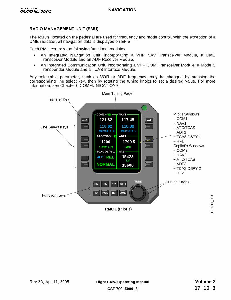
RADIO MANAGEMENT UNIT (RMU)
The RMUs, located on the pedestal are used for frequency and mode control. With the exception of aDME indicator, all navigation data is displayed on EFIS.
Each RMU controls the following functional modules:
• An Integrated Navigation Unit, incorporating a VHF NAV Transceiver Module, a DMETransceiver Module and an ADF Receiver Module.
• An Integrated Communication Unit, incorporating a VHF COM Transceiver Module, a Mode STransponder Module and a TCAS Interface Module.
Any selectable parameter, such as VOR or ADF frequency, may be changed by pressing thecorresponding line select key, then by rotating the tuning knobs to set a desired value. For moreinformation, see Chapter 6 COMMUNICATIONS.
Pilot’s Windows− COM1− NAV1− ATC/TCAS− ADF1− TCAS DSPY 1− HF1Copilot’s Windows− COM2− NAV2− ATC/TCAS− ADF2− TCAS DSPY 2− HF2
Main Tuning Page
Transfer Key
Line Select Keys
Function Keys
RMU 1 (Pilot’s)
Tuning Knobs
GF
1710
_003
COM1 NAV1
ATC/TCAS ADF1
TCAS DSPY 1 HF1
NB
MEMORY−4
1 ATC ALT
ALT:
121.82
118.02MEMORY−1
117.45
110.00
1200ADF
1799.5
REL
NORMAL 15600
15423LV
NAVIGATION
Rev 2A, Apr 11, 2005 Flight Crew Operating Manual
CSP 700−5000−6
Volume 217−10−3

VHF NAVIGATION RECEIVERS
The two VHF Navigation receivers (NAV 1 and NAV 2) provide VHF omnirange (VOR), Localizer(LOC), Glideslope (GS) and Marker Beacon (MB) signals to the navigation systems and flight crew.
The navigation receivers operate in the following ranges:
System Frequency Range Channel Spacing
VOR 108.00 to 117.9 MHz 50 kHz (160 chan)
LOC 108.10 to 111.95 MHz 50 kHz (40 chan)
GS 329.15 to 335.00 MHz 150 kHz (40 chan)
MB 75.00 MHz Preset
Frequency selection is through radio tuning units located on the pedestal.
COM1 NAV1
ATC/TCAS ADF1
TCAS DSPY 1 HF1
NB
MEMORY−4
1 ATC ALT
RANGE:
121.82
118.02MEMORY−1
117.45
110.00
1200ADF
1799.5
6
NORMAL 15600
15423LV
RMU 1 (Pilot’s) RMU 2 (Copilot’s) GF
1710
_004
COM2 NAV2
ATC/TCAS ADF2
TCAS DSPY 2 HF2
NB
MEMORY−4
1 TA/RA
RANGE:
123.45
127.95MEMORY−2
117.45
110.10
1200ADF
1799.5
6
NORMAL 15600
11233LV
NAVIGATION
Rev 2A, Apr 11, 2005Flight Crew Operating Manual
CSP 700−5000−6
Volume 217−10−4

NAV 1 (2)
The VHF NAV receiver houses the major navigation functions of the VOR/LOC receiver, glideslopereceiver and marker beacon receiver.
The NAV line select key is used to select navigation frequencies (VOR, LOC, GS and DME). Thecursor will automatically reposition to the NAV receiver active frequency after 17 seconds.
Pressing and holding NAV preselect key for more than 3 seconds moves cursor to the top and blanksthe preselect window and allows direct tuning of NAV receiver active frequency.
COM1 NAV1
ATC/TCAS ADF1
TCAS DSPY 1 HF1
NB
MEMORY−4
1 ATC ALT
ALT:
121.82
118.02MEMORY−1
117.45
110.00
1200ADF
1799.5
REL
NORMAL 15600
15423LV
COM1 NAV1
ATC/TCAS ADF1
TCAS DSPY 1 HF1
NB
MEMORY−4
1 ATC ALT
ALT:
121.82
118.02
117.45
1200ADF
1799.5
REL
NORMAL 15600
15423LV
NOTEPressing the NAV preselect key highlights the MEMORY window.Rotating the TUNE knob will scroll through the frequencies in MEMORY.
GF
1710
_005
Pressing the transfer key will toggle the Active and Preset frequencies, channeling the NAV receiverto what had been the Preset.
GF
1710
_006
COM1 NAV1
ATC/TCAS ADF1
TCAS DSPY 1 HF1
NB
MEMORY−4
1 ATC ALT
ALT:
121.82
118.02MEMORY−1
117.45
110.00
1200ADF
1799.5
REL
NORMAL 15600
15423LV
COM1 NAV1
ATC/TCAS ADF1
TCAS DSPY 1 HF1
NB
MEMORY−4
1 ATC ALT
ALT:
121.82
118.02
110.00
1200ADF
1799.5
REL
NORMAL 15600
15423LV
117.45TEMP − 1
NAVIGATION
Rev 2A, Apr 11, 2005 Flight Crew Operating Manual
CSP 700−5000−6
Volume 217−10−5

NAV 1 (2) (CONT'D)
While on the main tuning page, press the PGE button once to bring the NAV memory page into view.
DISABLED
110.00
110.30
115.60
116.50
108.70
111.80
RETURN
FMS
MEMORIES
1
2
3
MORE
DELETE
INSERT
4
5
6
NAV1
117.45COM1 NAV1
ATC/TCAS ADF1
TCAS DSPY 1 HF1
NB
MEMORY−4
1 ATC ALT
ALT:
121.82
118.02MEMORY−1
117.45
110.00
1200ADF
1799.5
REL
NORMAL 15600
15423LV
GF
1710
_007
An FMS autotuned VOR or ILS frequency is displayed on the main tuning page. To override an FMSautotuned VOR or ILS frequency, toggle the transfer key, or enter a new active frequency.
GF
1710
_008
ENABLED
1
2
3
4
5
6
RETURN
FMS
MEMORIES
MORE
DELETE
INSERT
110.00
110.30
115.60
116.50
108.70
111.80
NAV1
117.45 110.25 AUTO
118.02MEMORY−4
ALT:
MEMORY−1110.00
NB
RELNORMAL
1 ATC ALT ADF
LV
ADF1ATC/TCAS
HF1TCAS DSPY 1
COM1 NAV1
121.82
1200 1799.5
15423
15600
NAVIGATION
Rev 2A, Apr 11, 2005Flight Crew Operating Manual
CSP 700−5000−6
Volume 217−10−6

DISTANCE MEASURING EQUIPMENT (DME)
The DME simultaneously tracks four selected DME channels for distance, groundspeed and time tostation, as well as monitoring two additional channels for ident functions. DME dedicates two of thefour channels to the FMS.
In normal VOR/ILS/DME operations, one of the six DME channels is paired with the active frequencyand another with a preset frequency. Pushing the DME function key will split the NAV window on themain tuning page, allowing the active DME channel to be selected separate from the active VOR/ILSfrequency.
An H (hold) will be displayed to indicate that the distance display is not paired with the VOR/ILSnavigation data. When DME hold is no longer required, cycle the DME function button until the split isremoved from the NAV window.
H118.02MEMORY−4
RANGE:
NB
NORMAL
1 ATC ALT ADF
LV6
H118.02MEMORY−4
RANGE:
ADF
LV
NB
6NORMAL
1 ATC ALT
ADF1ATC/TCAS
HF1TCAS DSPY 1
COM1 NAV1
121.82 108.30
1200 1799.5
15423
15600
DME IZZ
111.90ADF1ATC/TCAS
HF1TCAS DSPY 1
COM1 NAV1
121.82 108.30
1200 1799.5
15423
15600
DME IUL
109.30
GF
1710
_009
NOTECycling the DME function button will display the following in sequence:VOR/ILS − VOR/ILS and DME − VOR/ILS and TACAN − VOR/ILS.
DME Hold
ILS/VORDME Ident
NAVIGATION
Rev 2A, Apr 11, 2005 Flight Crew Operating Manual
CSP 700−5000−6
Volume 217−10−7

AIR TRAFFIC CONTROL (ATC) TRANSPONDER
ATC Transponder operations are controlled by the adjacent line select keys and the tuning knobs.
Both RMUs will display the same transponder information. If a code or mode is changed on oneRMU, the other RMU will track it.
GF
1710
_010
118.02MEMORY−4
RANGE:
NB
NORMAL
1 ATC ALT ADF
LV6
ADF1ATC/TCAS
HF1TCAS DSPY 1
COM1 NAV1
121.82 108.30
1200 1799.5
15423
15600
DME IZZ
111.90
The transponder will go into ident mode for approximately 18 seconds when the ID function key ispushed and an ID annunciator will appear.
A reply annunciator (rectangular box), located in the upper right corner of the ATC window, will turnyellow, whenever the transponder is replying to an interrogation from a ground station or TCAS.When ID button is pressed, the reply annunciator will come on steady for approximately 20 seconds.
118.02MEMORY−4
ATC ID
RANGE:
NB
NORMAL
1 ATC ALT ADF
LV6
ADF1
HF1TCAS DSPY 1
COM1 NAV1
121.82 108.30
1200 1799.5
15423
15600
DME IUL
109.30G
F17
10_0
11
Reply Annunciator
Ident Annunciator
NAVIGATION
Rev 2A, Apr 11, 2005Flight Crew Operating Manual
CSP 700−5000−6
Volume 217−10−8
TRAFFIC ALERT AND COLLISION AVOIDANCE SYSTEM (TCAS)
The TCAS is an airborne system that interrogates ATC transponders in nearby airplanes to identifyand display potential and predicted collision threats, within 700 feet of closest point of approach.TCAS monitors a radius of up to 40 nautical miles about the airplane, computes range, bearing andclosure rate of up to 12 other transponder equipped airplanes relative to the “own” airplane. TCASand ATC transponder modes are set on the RMUs.
Active (interrogated) range is possible up to 70 to 100 NM depending on atmospheric conditions.Passive range to a distance of 120 NM is possible if intruder aircraft has a TCAS change 7 and aGPS installed.
The system provides appropriate aural and visual cues to the flight crew when TCAS computeranalysis of an airplane signal predicts a penetration of TCAS protected airspace.
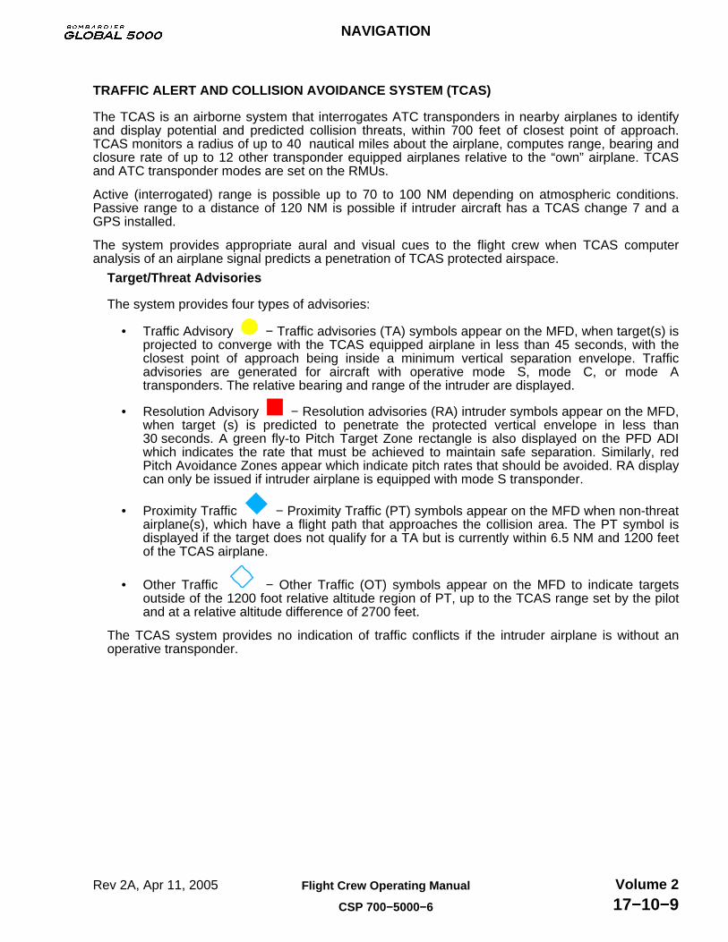
Target/Threat Advisories
The system provides four types of advisories:
• Traffic Advisory − Traffic advisories (TA) symbols appear on the MFD, when target(s) isprojected to converge with the TCAS equipped airplane in less than 45 seconds, with theclosest point of approach being inside a minimum vertical separation envelope. Trafficadvisories are generated for aircraft with operative mode S, mode C, or mode Atransponders. The relative bearing and range of the intruder are displayed.
• Resolution Advisory − Resolution advisories (RA) intruder symbols appear on the MFD,when target (s) is predicted to penetrate the protected vertical envelope in less than30 seconds. A green fly-to Pitch Target Zone rectangle is also displayed on the PFD ADIwhich indicates the rate that must be achieved to maintain safe separation. Similarly, redPitch Avoidance Zones appear which indicate pitch rates that should be avoided. RA displaycan only be issued if intruder airplane is equipped with mode S transponder.
• Proximity Traffic − Proximity Traffic (PT) symbols appear on the MFD when non-threatairplane(s), which have a flight path that approaches the collision area. The PT symbol isdisplayed if the target does not qualify for a TA but is currently within 6.5 NM and 1200 feetof the TCAS airplane.
• Other Traffic − Other Traffic (OT) symbols appear on the MFD to indicate targetsoutside of the 1200 foot relative altitude region of PT, up to the TCAS range set by the pilotand at a relative altitude difference of 2700 feet.
The TCAS system provides no indication of traffic conflicts if the intruder airplane is without anoperative transponder.
NAVIGATION
Rev 2A, Apr 11, 2005 Flight Crew Operating Manual
CSP 700−5000−6
Volume 217−10−9

TRAFFIC ALERT AND COLLISION AVOIDANCE SYSTEM (TCAS) (CONT'D)TCAS Symbology
THREAT LEVEL CAUSE SYMBOL
Resolution Advisory (RA)
Traffic Advisory (TA)
ProximateTraffic (PT)
OtherTraffic (OT)
Intruding aircraft is 100 feet above and descending at least 500 feet per minute.
Traffic is 1,200 feet below and climbing at least 500 feet per minute.
Intruding aircraft level with and not climbing or descending.
Traffic is 2,700 feet above and descending at least 500 feet per minute.
+01
−12
+27
Up Arrow Indicates climbing traffic.
Down Arrow Indicates descending traffic.
Plus Sign (+) Relative altitude threat, airplane is above own airplane.
Minus Sign (−) Relative altitude threat, airplane is below own airplane.
DEFINITIONDATA TAGS
GF
1710
_016
TCAS Modes
The following TCAS modes are selectable on the RMU:
• TA/RA Mode − Normal operation mode providing full TCAS coverage. TCAS tracks up to 12airplanes in the surrounding airspace and generates TAs and RAs as required.
• TA ONLY Mode − TCAS tracks all PT airplanes and generates TAs, no RAs. Automaticallyselected when airplane is flying lower than 1100 feet AGL (while climbing) or 900 feet AGL(while descending).
• TEST Mode − Pressing the TST button on the RMU, will start a self-test program that willverify proper operation of the TA and RA displays and of the aural advisories. The TESTmode does not affect normal TCAS operation. Should an actual TA or RA occur duringTEST sequence, the test is automatically terminated and the advisory is announced anddisplayed.
NAVIGATION
Rev 2A, Apr 11, 2005Flight Crew Operating Manual
CSP 700−5000−6
Volume 217−10−10

TRAFFIC ALERT AND COLLISION AVOIDANCE SYSTEM (TCAS) (CONT'D)ATC/TCAS Mode Select
ATC/TCAS operations are controlled by the adjacent line select keys and the tuning knobs.
The modes are:
• ATC ON − Replies on Modes S and A, no altitude reporting.
• ATC ALT − Replies on Modes A, C and S, with altitude reporting.
• STANDBY − Transponder in standby mode.
• TA ONLY − TCAS traffic advisory mode selected.
• TA/RA − TCAS traffic advisory/resolution advisory mode selected.
10000
1
23
1
23
DME
RANGE:
118.02MEMORY−4
TA ONLY
NB
NORMAL
ADF
LV6
ADF1ATC/TCAS
HF1TCAS DSPY 1
COM1 NAV1
121.82 108.30
1200 1799.5
15423
15600
IZZ
111.90
TA ONLY
NOTEPressing adjacent line key will annunciate STBY or displayed mode.
NOTERotating the tuning knob will select ATC ON, ATC ALT, TA ONLY or TA/RA. G
F17
10_0
17
The PGE function key provides access to a menu page. The menu allows access to the TCASoperational selections.
ATC/TCAS CONTROL PAGE
INTRUDER ALTITUDE: REL
TA DISPLAY ; AUTO
ATC ALT : 1 2500
RETURN TO RADIOS
INTRUDER ALTITUDE
REL Targets altitude displayed relative to one’s own airplane.
− FL Targets altitude displayed as a flight level, for 20 seconds,then returns to REL.
TA DISPLAYAUTO Traffic targets displayed only when a TA or RA target
condition exists.MANUAL All traffic targets displayed within the viewing airspace.
RETURN TO RADIOS
Returns to main tuning page.
ATC ALT 1, (2) Indicates that the transponder selected on the main tuning
page is communicating at a displayed pressure altitude.This is not a control feature, only a cross check.
GF
1710
_018
NAVIGATION
Rev 2A, Apr 11, 2005 Flight Crew Operating Manual
CSP 700−5000−6
Volume 217−10−11

TRAFFIC ALERT AND COLLISION AVOIDANCE SYSTEM (TCAS) (CONT'D)TCAS DSPY 1 (2) Select
The primary TCAS selection is selected via the adjacent line select keys. The TCAS selections areas follows:
• Range − Selectable at 6, 12, 20, 40, 80, and 120 NM.• Altitude Band Select −
NORMAL : With TA display set to AUTO, ± 1200 feet TCAS display altitude.With TA display set to MANUAL, ± 2700 feet TCAS display altitude.
ABOVE : +7000 feet, −2700 feet TCAS display altitude.
BELOW : −7000 feet, +2700 feet TCAS display altitude.
RANGE:
118.02MEMORY−4
NB
6NORMAL
1 ATC ALT ADF
LV
ADF1ATC/TCAS
HF1TCAS DSPY 1
COM1 NAV1
121.82 108.30
1200 1799.5
15423
15600
DME IZZ
111.90
NOTE
GF
1710
_019
Rotate the tuning knob to change therange when adjacent line select keyis selected.Rotate the tuning knob to change the altitudeband select when adjacent line select keyis selected.
TCAS Mode Select Annunciation
The indications for intruder alert and altitude band selections are as follows:
GF
1710
_020
REL
4000
KDVT
1+36
12.5KDVT
ABOVE
ETE
NM
KPHXTOC
KSRP
4000
FL180
ABOVE
6
+10REL
TCAS Zoom Window MFD (MAP format)
NAVIGATION
Rev 3, Apr 25, 2005Flight Crew Operating Manual
CSP 700−5000−6
Volume 217−10−12

TRAFFIC ALERT AND COLLISION AVOIDANCE SYSTEM (TCAS) (CONT'D)TCAS Mode Select Annunciation (Cont’d)
The indications for TCAS TEST are as follows:
−04
+12
+10
360
−11
−03
+20
+03
TCAS TEST
6
12.5 NMTCAS TEST
N
20 20
30
6
33 3
GF
1710
_021TCAS TEST (when test initiated), then
TCAS TEST PASSor
TCAS TEST FAIL
TCAS Status Messages
TCAS status messages are annunciated as follows:
TCAS Status Message Area
GF
1710
_022
a
−Indicates resolution advisory failure.
−Indicates that TCAS has been selected to
−Indicates a functional test is in progress.−Indicates TCAS failure.
−Indicates TCAS is selected and transponder is in STBY.
traffic advisories only
TCAS STBY
TCAS TESTTCAS FAIL
TA ONLY
RA FAIL
10000
1
2
3
1
2
3
TCAS FAIL
Digitized Voice
TCAS will provide voice warnings. The voice warnings cannot be cancelled or reduced in volume.TA voice warning is “TRAFFIC, TRAFFIC“
RA voice warnings are:
• ADJUST VERTICAL SPEED, ADJUST.• CLEAR OF CONFLICT• CLIMB, CLIMB NOW! − CLIMB, CLIMB NOW!• CLIMB, CROSSING CLIMB − CLIMB, CROSSING CLIMB.• CLIMB − CLIMB.• DESCEND, CROSSING DESCEND − DESCEND, CROSSING DESCEND.• DESCEND, DESCEND NOW! − DESCEND, DESCEND NOW!• DESCEND − DESCEND.• INCREASE CLIMB − INCREASE CLIMB.• INCREASE DESCENT − INCREASE DESCENT.• MAINTAIN VERTICAL SPEED, CROSSING MAINTAIN.• MAINTAIN VERTICAL SPEED, MAINTAIN.• MONITOR VERTICAL SPEED, MONITOR VERTICAL SPEED.
NAVIGATION
Rev 2A, Apr 11, 2005 Flight Crew Operating Manual
CSP 700−5000−6
Volume 217−10−13

TRAFFIC ALERT AND COLLISION AVOIDANCE SYSTEM (TCAS) (CONT'D)Resolution Advisories
TCAS resolution advisories and status messages are displayed on the PFDs. The verticalmaneuver is also accompanied by TCAS voice warnings.
Resolution Advisory Indication
CORRECTIVE ACTION
CLEAROF
CONFLICT
INDICATIONCLIMBCLIMB
DESCENDDESCEND
FG
F17
10_0
01
Green rectangle advises pilot of fly-to-zone.Red avoidance zone advises pilot to fly out of, or do not enter indicated area.
avoidance zone advises pilot to fly out of,
20 20
10 10
20 20
10 10
NAVIGATION
Rev 2A, Apr 11, 2005Flight Crew Operating Manual
CSP 700−5000−6
Volume 217−10−14
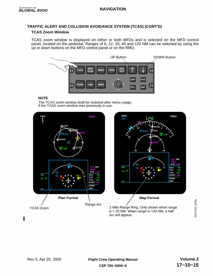
TRAFFIC ALERT AND COLLISION AVOIDANCE SYSTEM (TCAS) (CONT'D)TCAS Zoom Window
TCAS zoom window is displayed on either or both MFDs and is selected on the MFD controlpanel, located on the pedestal. Ranges of 6, 12, 20, 40 and 120 NM can be selected by using theup or down buttons on the MFD control panel or on the RMU.
2 Mile Range Ring. Only shown when range is < 20 NM. When range is >20 NM, a half arc will appear.
+12
−02
315
KLAX
−04
+10
TERR OFF
1+36
345
12.5KDVT
KDVT
WX
T5 . 0
LX
LUF
360
234−40−56
+12
−02
WX
T5 . 0
LX
LUF
+10
KLAX
−04
TERR OFF
345234−40−56
1+36
12.5KDVT
KDVT
FMS1TRU
N
50 50KPHX
TOC
KSRP
KLAX
ETE
NM
6
HDG
ETE
NM
FMS1
N
50 50
KPHX
TOC
KSRP
6
Range ArcTCAS Zoom
GSPD
TATTAS
SAT GSPD
TATTAS
SAT
30
6
33 3
GF
1710
_024
a
UP Button DOWN Button
NOTEThe TCAS zoom window shall be restored after menu usage,if the TCAS zoom window was previously in use.
Plan Format Map Format
NAVIGATION
Rev 3, Apr 25, 2005 Flight Crew Operating Manual
CSP 700−5000−6
Volume 217−10−15

TRAFFIC ALERT AND COLLISION AVOIDANCE SYSTEM (TCAS) (CONT'D)TCAS Traffic Display (MAP Format)
The TCAS overlay is the default condition on the MFD during power-up. TCAS display can also beenabled on MAP format and is selected through the TCAS button on the MFD control panel. TCAScannot be displayed on PLAN format.
315
TERR OFF
−40
LX
360
LUF
WX
234
−56
1+36
12.5KDVT
KDVT
KDVT
4000345
FMS1
The button sequence is as follows:not shown − TCAS zoom window − TCAS overlay − TCAS zoom window − not shown
HDG
ETE
NM
N
20 20
KPHX
KPHX
TOC
TOC
KSRP
4000
FL180
KSRP
GSPD
TATTAS
SAT
30
6
33 3
−04
+12
315
LX
360
LUF
WX1+36
12.5KDVT
KDVT
KDVT
4000GSPD
TATTAS
−40234345
−56SAT
TERR IOFF
FMS1HDG
ETE
NM
N
20 20
KPHX
KPHX
TOC
TOC
KSRP
4000
FL180
KSRP
+10
30
6
33 3
GF
1710
_025
a
NOTETCAS STBY, TA ONLY, TCAS, TCAS FAIL (amber), TCAS TEST (red)are available annunciations.
TCAS not shown TCAS overlay
NOTE
TCAS STBY msg displayed on MFD and PFD when TCAS isselected with transponder in STBY.
NAVIGATION
Rev 3, Apr 25, 2005Flight Crew Operating Manual
CSP 700−5000−6
Volume 217−10−16
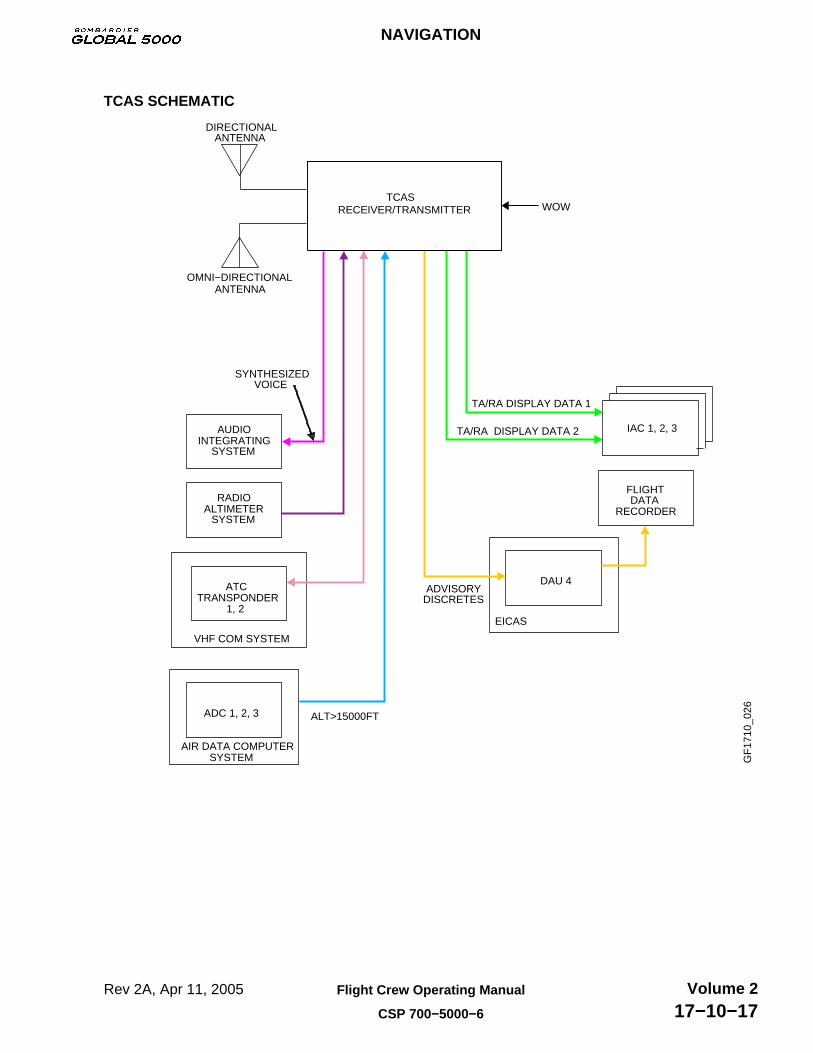
TCAS SCHEMATIC
FLIGHTDATA
RECORDER
ADVISORYDISCRETES
ATCTRANSPONDER
1, 2
RADIOALTIMETER
SYSTEM
OMNI−DIRECTIONALANTENNA
AUDIO INTEGRATING
SYSTEM
IAC 1, 2, 3
DIRECTIONAL ANTENNA
TCASRECEIVER/TRANSMITTER WOW
SYNTHESIZEDVOICE
TA/RA DISPLAY DATA 1
TA/RA DISPLAY DATA 2
DAU 4
EICAS
ADC 1, 2, 3
AIR DATA COMPUTER SYSTEM
ALT>15000FT
VHF COM SYSTEM
GF
1710
_026
NAVIGATION
Rev 2A, Apr 11, 2005 Flight Crew Operating Manual
CSP 700−5000−6
Volume 217−10−17

AUTOMATIC DIRECTION FINDER (ADF)
The two ADF receivers (ADF1 and ADF2) provide relative bearing between the airplane and aselected ground station for display on the PFDs. ADF operations are controlled by the adjacent lineselect keys and the tuning knobs. For more information, see Chapter 6 COMMUNICATIONS.
NB
6NORMAL
1 ATC ALT ADF
LV
118.02
RANGE:
ADF1ATC/TCAS
HF1TCAS DSPY 1
COM1 NAV1
121.82 108.30
1200 1799.5
15423
15600
DME IZZ
111.90
GF
1710
_027
The receivers operate in the following modes and are controlled by the adjacent line select keys orthe tuning knobs.
118.02
RANGE:
NB
6NORMAL
1 ATC ALT
LV
ADF
ADF1ATC/TCAS
HF1TCAS DSPY 1
COM1 NAV1
121.82 108.30
1200 1799.5
15423
15600
DME IZZ
111.90
GF
1710
_028
VOICE Maximum audio clarity and fidelity, no bearing.
BFO ADF adds a beat frequency oscillator (BFO) for detection of
ADF Bearing determination. Some loss of received audio range and sensitivity.
ANT Maximum sensitivity and range. Aural beacon ident and voice only, no bearing.
cw signals.
NAVIGATION
Rev 2A, Apr 11, 2005Flight Crew Operating Manual
CSP 700−5000−6
Volume 217−10−18

BEARING (BRG) SOURCE
Bearing information, VOR1, ADF1 or FMS1 and bearing information VOR2, ADF2 or FMS2, isselected on either the pilot’s and/or the copilot’s PFD control panel, located on the glareshield.
VOR1
ADF 1
FMS 1
VOR2
ADF 2
FMS 2
NOTEPushing BRG button (s) will toggle the following in sequence:
− VOR− ADF− FMS− Blank G
F17
10_0
29
PFD Control Panel
HDG030
VOR1
CRS360
VOR 2
3N 6
33
E
W
2421
s
15
30
1212
HDG030
VOR1
3N 6
33
E
W
2421
s
15
30
RAD BAROMINIMUMS NAV SCR BARO SET
PUSH STD
HPaIN
RAD BAROMINIMUMS NAV SCR BARO SET
PUSH STD
HPaIN
NAVIGATION
Rev 2A, Apr 11, 2005 Flight Crew Operating Manual
CSP 700−5000−6
Volume 217−10−19

VOR/LOC NAV SOURCE
NAV source, VOR/LOC, is selectable on the pilot’s and/or the copilot’s PFD control panel.
PILOT’S PFD
NOTEPushing V/L button will toggle the NAV source in the following sequence:on-side VOR/LOC − X-side VOR/LOC − on-side VOR/LOC
On-side
PILOT’S PFD COPILOT’S PFD
NOTE If FMS is the primary NAV source, the first push of the V/L button will set preview NAV source. The second push of V/L button will cancel FMS as primary NAV source and setVOR/LOC as primary NAV source.
PREVIEW NAV SOURCE
PREVIEW COURSEPOINTER
X-side
COPILOT’S PFD
GF
1710
_030
HDG030
VOR1
VOR1CRS360
3N 6
33
E
W
2421
s
15
30
12
HDG030
VOR2CRS360
VOR 2
3N 6
33
E
W
2421
s
15
30
12
HDG030
VOR2CRS360
VOR 2
3N 6
33
E
W
2421
s
15
30
12
HDG030
VOR2CRS360
VOR 2
3N 6
33
E
W
2421
s
15
30
12
LOC1FMS1
DTK360
3N 6
33
E
W
2421
s
15
30
12
HDG330
NAV SCR
NAVIGATION
Rev 2A, Apr 11, 2005Flight Crew Operating Manual
CSP 700−5000−6
Volume 217−10−20

FMS NAV SOURCE
FMS source, FMS1, FMS2, FMS3 (if installed) or Navigation Display Unit (NDU), also referred to asLasertrack (LTRK) (if installed) is selectable on the pilot’s and/or the copilot’s PFD control panel.
NOTEPushing FMS button will toggle the NAV source in the following sequence:on-side FMS − X-side FMS − LTRK (if installed) − on-side FMS or,on-side FMS − FMS3 (if installed) − X-side FMS − on-side FMS.
NOTE If V/L is the primary NAV source, pushing the FMS button will cancel V/L as primary NAVsource and will set on-side FMS as primary NAV source. Pushing FMS button while V/Lpreview NAV source is displayed, will cancel preview NAV source.
On-side
X-side
GF
1710
_031
PILOT’S PFD COPILOT’S PFD
PILOT’S PFD COPILOT’S PFD
HDG360
FMS1DTK030
3N 6
33
E
W
2421
s
15
30
12
HDG360
FMS2DTK060
3N 6
33 E
W
2421
s
15
30
12
HDG360
FMS1DTK030
3N 6
33
E
W
2421
s
15
30
12
HDG360
FMS1DTK030
3N 6
33
E
W
2421
s
15
30
12
NAV SCR
NAVIGATION
Rev 2A, Apr 11, 2005 Flight Crew Operating Manual
CSP 700−5000−6
Volume 217−10−21

WEATHER RADAR (WX)
The weather radar control panel, located on the pedestal, controls GAIN, RADAR modes, TILT andLightning Sensor System (LSS) (if installed). It also enables turbulence (TRB) mode, antennastabilization (STAB), target alert (TGT) and sector scan (SECT).
TRB ButtonUsed to determine if turbulence is present in WX mode at 50 NM or less.
STAB ON/OFF ButtonUsed to enable or disable antenna stabilization.
TGT ButtonUsed to detect weather conditions beyond selected range.
SECT ButtonUsed to select either the normal scan (120°) or alternate scan (60°).
GAIN KnobUsed to controlreceiver gain.
RADAR Rotary KnobUsed to select the following functions:
OFF − Turns the radar system off.SBY − Selects standby mode, stops
antenna scan and transmitter.
WX − Selects weather radar mode.
RCT − Selects rain echo attenuation compensation technique.
GMAP − Selects ground mapping mode.
FP − Selects flight plan mode.
TST − Selects the radar test mode.
Lightning Sensor System (LSS) (if installed)Used to select the following LSS operating modes:
OFF − Turns the LSS off.
SBY − Selects standby mode.
LX − Displays LSS data on MFD.
CLR/TST − Selects test mode.
TILT KnobUsed to select tilt angle.Clockwise rotation tilts beam upward to +15°, counterclockwise tilts the beam downward to −15°.
SLV AnnunciatorComes on to indicate which radar is slaved to the primary. The primary is the first WX turned on.
GF
1710
_032
SLV
NAVIGATION
Rev 2A, Apr 11, 2005Flight Crew Operating Manual
CSP 700−5000−6
Volume 217−10−22
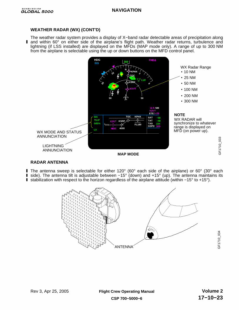
WEATHER RADAR (WX) (CONT'D)
The weather radar system provides a display of X−band radar detectable areas of precipitation alongand within 60° on either side of the airplane’s flight path. Weather radar returns, turbulence andlightning (if LSS installed) are displayed on the MFDs (MAP mode only). A range of up to 300 NMfrom the airplane is selectable using the up or down buttons on the MFD control panel.
MAP MODE
WX MODE AND STATUS ANNUNCIATION
LIGHTNINGANNUNCIATION
WX Radar Range10 NM
25 NM
50 NM
100 NM
200 NM300 NM
NOTE
GF
1710
_033
TOC
KSRP
HDG315
ETE1+36
12.5KDVT
NM
FMS1360
N
50 50
KPHX
LUF
KDVT
KPHXTOC
KSRPKDVT
4000 4000
FL180
WXT5.0 G85%
LX
SAT
GSPD
−56TATTAS
−40234345
30 6
33 3
WX RADAR willsynchronize to whateverrange is displayed onMFD (on power up).
RADAR ANTENNA
The antenna sweep is selectable for either 120° (60° each side of the airplane) or 60° (30° eachside). The antenna tilt is adjustable between −15° (down) and +15° (up). The antenna maintains itsstabilization with respect to the horizon regardless of the airplane attitude (within −15° to +15°).
GF
1710
_034
ANTENNA
NAVIGATION
Rev 3, Apr 25, 2005 Flight Crew Operating Manual
CSP 700−5000−6
Volume 217−10−23

MODE SELECTION
The weather radar operating modes, gain and antenna tilt functions are all controlled by the tworadar control panels. Both the pilot and copilot can look at different ranges and tilt settings at thesame time on their respective MFDs.
The weather radar modes and features are as follows:
TRB − Momentarily pressing the TRB button enables the turbulence mode. When this mode isselected, the radar determines if turbulence is present. TRB can only be engaged in the WX modeand in selected ranges of 50 NM or less. The weather/turbulence WX/T mode is annunciated in thestatus display. Areas of at least moderate turbulence are shown in white.
ANNUNCIATION
N
20 20
KPHXTOC
KSRPKDVT
4000 4000
FL180
WX
G85% LX
SAT
GSPD
−56TATTAS
−40234345
30 6
33 3
GF
1710
_035
T5.0
STAB − Momentarily pressing the STAB button, holds the elevation of the antenna beam constant atall azimuths, regardless of airplane bank or pitch maneuvers and relative to the earth’s surface. Thestabilization system uses IRS as a reference. Momentarily pressing the STAB button disablesantenna stabilization and STAB is annunciated in the status display.
KPHXTOC
KSRPKDVT
4000 4000
FL180
WX
G85% STAB
SAT
GSPD
−56TATTAS
−40234345
GF
1710
_036
ANNUNCIATION
T5.0
NAVIGATION
Rev 2A, Apr 11, 2005Flight Crew Operating Manual
CSP 700−5000−6
Volume 217−10−24

MODE SELECTION (CONT'D)
TGT − Target alert monitors for red or magenta weather conditions (rainfall rate) beyond the selectedrange and 7.5° on each side of the airplane heading and is selectable in all but the 300 NM range. Ifsuch weather is detected, outside the selected range the TGT alert annunciation changes from greenarmed to an amber alert condition on the MFD WX Status display. When this warning is received, thepilot should select longer ranges to view target alert. When TGT button is selected, TGTannunciation will replace the GAIN annunciation in the status display.
TGT will be displayed as TGT (flashing), if red or magenta is detected outside selected range.
Rainfall Rate
RAINFALL COLOUR CODING
in/hr mm/hrColour
.04 to .16 1 to 4
.16 to .47 4 to 12
.47 to 2.0 12 to 50>2 >50 KPHXTOC
KSRPKDVT
4000 4000
FL180
WX
TGT
SAT
GSPD
−56TATTAS
−40234345
GF
1710
_037
T5.0
SECT − The normal radar sweep is ± 60° from the airplane nose at a rate of 14 sweeps/min.Pressing SECT button reduces the angle of sweep to ± 30° at a rate of 28 sweeps/min. Pressing theSECT button again, returns to normal sweep. Both the pilot’s and copilot’s displays will show thesame sweep angle.
N
50 50
N
50 50
30 6
33 3
30 6
33 3
GF
1710
_038
120° arc 60° arc
GAIN − The GAIN knob is a rotary control and push/pull switch that is used to control the receivergain. Push on the GAIN switch to enable the preset calibrated gain mode. Calibrated gain is thenormal mode and is used for weather avoidance. Pull out on the GAIN switch to enable the variablegain mode. Variable gain is used to provide additional weather analysis and for ground mapping. InWX mode, variable gain receiver sensitivity can be increased to show weak targets or can bereduced to eliminate weak returns.
ANNUNCIATION
KPHXTOC
KSRPKDVT
4000 4000
FL180
WX
G85%
SAT
GSPD
−56TATTAS
−40234345
GF
1710
_039
T5.0
NAVIGATION
Rev 2A, Apr 11, 2005 Flight Crew Operating Manual
CSP 700−5000−6
Volume 217−10−25

WX SYSTEM OPERATION
The RADAR rotary knob is used to select the following functions:
OFF − Turns the radar off. The system is no longer radiating and the antenna is stowed.
KPHXTOC
KSRPKDVT
4000 4000
FL180
SAT
GSPD
−56TATTAS
−40234345
WX/OFF
TGT
GF
1710
_040
ANNUNCIATION
T5.0
SBY − Selects the WX system in standby mode. It takes approximately 45 seconds for the system towarm up after being switched out of OFF. There is also a hidden mode, Forced Standby (FSBY).This mode is enabled automatically on the ground, if the airplane is powered up, with the radarpowered. To exit FSBY, push STAB button 4 times within 3 seconds. This mode prevents the radarfrom radiating, thereby protecting the ground personnel from radiation exposure.
STBY
TGT
FSBY KPHXTOC
KSRPKDVT
4000 4000
FL180
SAT
GSPD
−56TATTAS
−40234345
GF
1710
_041
ANNUNCIATION
T5.0
WX − Selects the WX mode of operation. When WX is selected, airplane inflight, the system is fullyoperational and all parameters are set for enroute weather detection. If the rotary knob is moveddirectly from OFF to WX, the system will first go into SBY for approximately 45 seconds, thenbecome active.
KPHXTOC
KSRPKDVT
4000 4000
FL180
WXT5.0 TGT
SAT
GSPD
−56TATTAS
−40234345
GF
1710
_042
ANNUNCIATION
NAVIGATION
Rev 2A, Apr 11, 2005Flight Crew Operating Manual
CSP 700−5000−6
Volume 217−10−26

WX SYSTEM OPERATION (CONT'D)
RCT − Enables the Rain Attenuation Compensation Technique (REACT). The REACT compensatesfor attenuation of the radar signal as it passes through rainfall. Strong targets (high attenuationlevels) cause the receiver to reach its maximum gain value in a short time/short range. Weak targets(low attenuation levels) cause the receiver to reach its maximum gain in a longer time/longer range.When this maximum gain value is reached, a cyan background field will appear. Any target inside ofthe cyan area will appear in magenta colour, indicating maximum severity.
25 25
N
KPHXTOC
KSRPKDVT
4000 4000
FL180
WX/R/T
TGT
SAT
GSPD
−56TATTAS
−40234345
30 633 3
GF
1710
_043
ANNUNCIATION
T5.0
GMAP − Selects the ground mapping mode. The auto TILT control is turned down until the desiredamount of terrain is displayed. The colour scheme is changed to cyan (least reflective return), yellow(moderate return) and magenta (strong return).
100 100
N
KPHXTOC
KSRPKDVT
4000 4000
FL180
GMAP
TGT
SAT
GSPD
−56TATTAS
−40234345
30 6
3
GF
1710
_044
ANNUNCIATION
33
T5.0
FP − Selects the flight plan mode. This clears the screen of radar data so ancillary data can bedisplayed, such as navigation displays and lightning data. In the FP mode the radar RTA is put tostandby and the FPLN legend is displayed in the mode field.
KPHXTOC
KSRPKDVT
4000 4000
FL180
FPLN SAT
GSPD
−56TATTAS
−40234345
GF
1710
_045
ANNUNCIATION
NAVIGATION
Rev 2A, Apr 11, 2005 Flight Crew Operating Manual
CSP 700−5000−6
Volume 217−10−27

WX SYSTEM OPERATION (CONT'D)
TST − Selects the test mode. The test position selects a special test pattern, to verify systemoperation. When the TEST is complete, the radar enters the FSBY mode.
TEST KPHXTOC
KSRPKDVT
4000 4000
FL180
SAT
GSPD
−56TATTAS
−40234345
GF
1710
_046
ANNUNCIATION
NAVIGATION
Rev 2A, Apr 11, 2005Flight Crew Operating Manual
CSP 700−5000−6
Volume 217−10−28
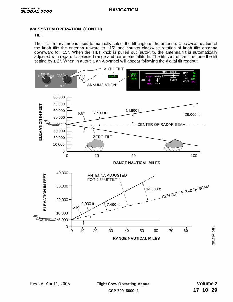
WX SYSTEM OPERATION (CONT'D)TILT
The TILT rotary knob is used to manually select the tilt angle of the antenna. Clockwise rotation ofthe knob tilts the antenna upward to +15° and counter-clockwise rotation of knob tilts antennadownward to −15°. When the TILT knob is pulled out (auto-tilt), the antenna tilt is automaticallyadjusted with regard to selected range and barometric altitude. The tilt control can fine tune the tiltsetting by ± 2°. When in auto-tilt, an A symbol will appear following the digital tilt readout.
AUTO-TILT
GF
1710
_048
a
4000
KDVT234
−56−40
345
KPHXTOC
KSRP
4000
FL180
GMAP
G85%
SAT
GSPD
TATTAS
ANNUNCIATION
T5.0 A T5.0
80,000
70,000
60,000
50,000
30,000
20,000
10,000
00 1005025
CENTER OF RADAR BEAM
ZERO TILT
7,400 ft5.6°14,800 ft
29,000 ft
RANGE NAUTICAL MILES
ELE
VA
TIO
N IN
FE
ET
40,000
30,000
20,000
10,000
5,000
00 10
CENTER OF RADAR BEAM
ANTENNA ADJUSTED
7,400 ft5.6°
14,800 ft
RANGE NAUTICAL MILES
ELE
VA
TIO
N IN
FE
ET
20 30 40 50 60 70 80
FOR 2.8° UPTILT
3,000 ft
NAVIGATION
Rev 2A, Apr 11, 2005 Flight Crew Operating Manual
CSP 700−5000−6
Volume 217−10−29

WX SYSTEM OPERATION (CONT'D)TILT MANAGEMENT
The pilot can use tilt management techniques to minimize ground clutter when viewing weathertargets.
Assume the aircraft is flying over relatively smooth terrain that is equivalent to sea level in altitude.The pilot must make adjustments for the effects of mountainous terrain.
The following figure helps to visualize the relationship between tilt angle, flight altitude, andselected range. It shows:
• Distance above and below aircraft altitude that is illuminated by the flat-plate radiator duringlevel flight with 0° tilt.
• Respective low altitude situation, with the antenna adjusted for 2.8° up-tilt.
AUTO-TILT
GF
1710
_048
a
4000
KDVT234
−56−40
345
KPHXTOC
KSRP
4000
FL180
GMAP
G85%
SAT
GSPD
TATTAS
ANNUNCIATION
T5.0 A T5.0
80,000
70,000
60,000
50,000
30,000
20,000
10,000
00 1005025
CENTER OF RADAR BEAM
ZERO TILT
7,400 ft5.6°14,800 ft
29,000 ft
RANGE NAUTICAL MILES
ELE
VA
TIO
N IN
FE
ET
40,000
30,000
20,000
10,000
5,000
00 10
CENTER OF RADAR BEAM
ANTENNA ADJUSTED
7,400 ft5.6°
14,800 ft
RANGE NAUTICAL MILES
ELE
VA
TIO
N IN
FE
ET
20 30 40 50 60 70 80
FOR 2.8° UPTILT
3,000 ft
NAVIGATION
Rev 2A, Apr 11, 2005Flight Crew Operating Manual
CSP 700−5000−6
Volume 217−10−30
WX SYSTEM OPERATION (CONT'D)TILT MANAGEMENT (Cont’d)
The following figure gives the approximate tilt settings at which ground targets begin to bedisplayed on the image periphery for an 18-inch radiator. The range at which ground targetscan be oberved is affected by the curvature of the earth, the distance from the aircraft to thehorizon, and altitude above the ground. As the tilt control is rotated downward, groundtargets first appear on the display at less than maximun range.
To find the ideal tilt angle after the aircraft is airborne, adjust the TILT control so that groundclutter does not interfere with viewing of weater targets. Usually, this can be done by tiltingthe antenna downward in 1° increments until ground targets begin to appear at the displayperiphery. Ground returns can be distinguished from strong storm cells by watching forcloser ground tragets that are displayed.
When ground targets are displayed, move the tilt angle upward in 1° increments until theground targets begin to disappear. Proper tilt adjustment is a pilot judgment, but typically thebest tilt angle lies where ground targets are barely visible or just off the radar image.
NAVIGATION
Rev 2A, Apr 11, 2005 Flight Crew Operating Manual
CSP 700−5000−6
Volume 217−10−31
WX SYSTEM OPERATION (CONT'D)TILT MANAGEMENT (Cont’d)
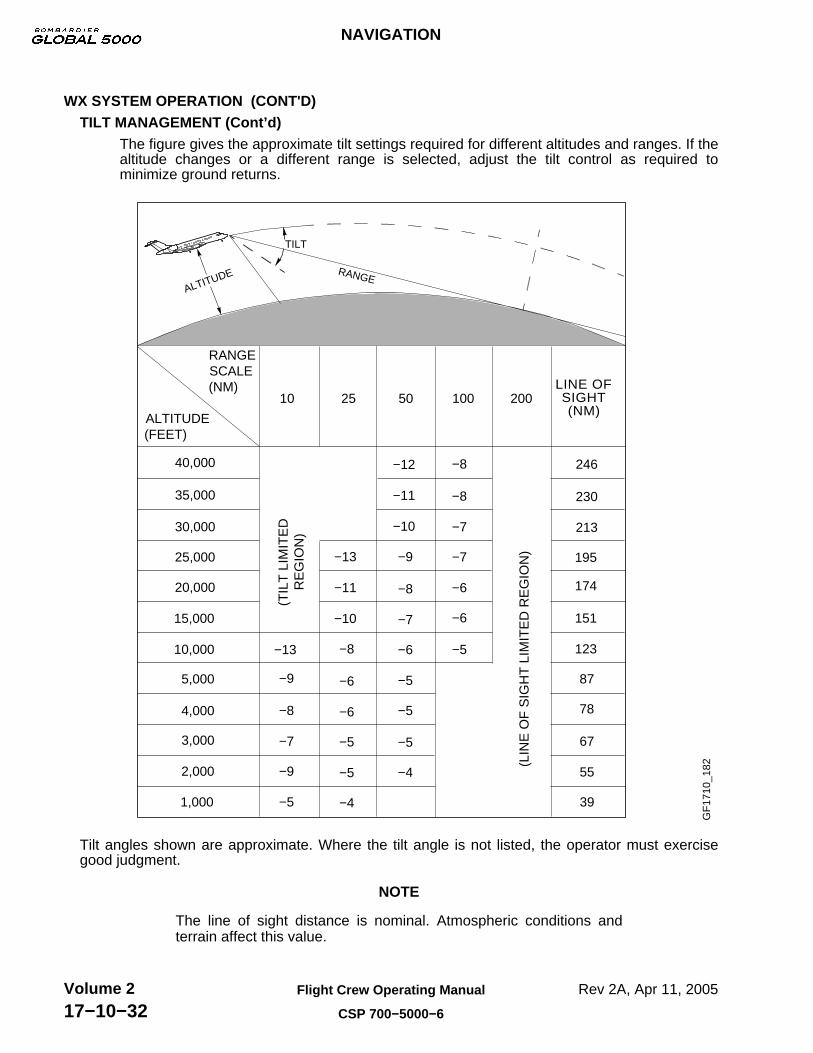
The figure gives the approximate tilt settings required for different altitudes and ranges. If thealtitude changes or a different range is selected, adjust the tilt control as required tominimize ground returns.
GF
1710
_182
LINE OFSIGHT(NM)
RANGESCALE(NM)
ALTITUDE(FEET)
10 25 50 100 200
40,000
35,000
30,000
25,000
20,000
15,000
10,000
5,000
4,000
3,000
2,000
1,000 39
55
67
78
87
123
151
174
195
213
230
246
−5
−9
−7
−8
−9
−13
−13
(LIN
E O
F S
IGH
T L
IMIT
ED
RE
GIO
N)
(TIL
T L
IMIT
ED
RE
GIO
N)
−11
−10
−5
−5
−6
−6
−8
−4
−12
−11
−10
−5
−6
−7
−8
−9
−5
−5
−4
−6
−7
−7
−8
−8
−6
−5
ALTITUDE
TILT
RANGE
Tilt angles shown are approximate. Where the tilt angle is not listed, the operator must exercisegood judgment.
NOTE
The line of sight distance is nominal. Atmospheric conditions andterrain affect this value.
NAVIGATION
Rev 2A, Apr 11, 2005Flight Crew Operating Manual
CSP 700−5000−6
Volume 217−10−32

WX SYSTEM OPERATION (CONT'D)TILT MANAGEMENT (Cont’d)
For more information on WX Radar, see manufacturer’s Manual A28−146−102−00.
NAVIGATION
Rev 2A, Apr 11, 2005 Flight Crew Operating Manual
CSP 700−5000−6
Volume 217−10−33

LIGHTNING SENSOR SYSTEM (LSS) (IF INSTALLED)
The lightning sensor system is used to detect lightning. The LSS rotary knob is used to select thefollowing functions:
OFF − Turns off the LSS.
KDVT
4000345234
−56−40
GMAP
TGT LX OFF
(If installed)
KPHXTOC
KSRP
4000
FL180
SAT
GSPD
TATTAS
GF
1710
_049
ANNUNCIATION
T5.0
SBY − Selects the LSS in standby mode. The data is inhibited, but LSS accumulates data.
KDVT
4000345
−56−40234
GMAP
TGT STBY
KPHXTOC
KSRP
4000
FL180
SAT
GSPD
TATTAS
GF
1710
_050
ANNUNCIATION
T5.0
LX − LSS is fully operational and displays data on the MFD.
KDVT
4000
234
−56−40
345
GMAP
TGT LX
N
50 50
Rate 1: Lightning rate of 2−15 strokes in the last 2 minutes.
Rate 2: Lightning rate of 16−31 strokes in the last 2 minutes.
Rate 3: Lightning rate of >32 strokes in the last 2 minutes.
ALERT: Range is indeterminate but bearing accurately determined. Azimuth should be closely monitored.
KPHXTOC
KSRP
4000
FL180
SAT
GSPD
TATTAS
30 6
33 3
GF
1710
_051
ANNUNCIATION
T5.0
CLR/TST − LSS accumulated data is cleared from memory. After 3 seconds the test mode isinitiated.
345
KDVT
4000
−40−56
234
GMAP
TGT LX/T
KPHXTOC
KSRP
4000
FL180
SAT
GSPD
TATTAS
GF
1710
_052
ANNUNCIATION
T5.0
For more information on Lightning Sensor System, see manufacturer’s manual.
NAVIGATION
Rev 2A, Apr 11, 2005Flight Crew Operating Manual
CSP 700−5000−6
Volume 217−10−34

WEATHER RADAR SCHEMATIC
MFDCONTROLLER 2
IAC 1 IAC 1IAC 2 IAC 2
IAC 3 IAC 3
PILOT’S WX CONTROLLER COPILOT’S WX CONTROLLER
WOW
WX RECEIVER/TRANSMITTER/ANTENNA
DU 5DU 2
IRU 2
WOW WOW
CAIMS
MFDCONTROLLER 1
GF
1710
_053
SLV SLV
IRU 1
TOC1+36
KDVT
4000
KDVT
360
−40−56
234
LX
345
0.05WX00:10
315
ET
GSPD
TATTAS
L
HDG
ETE
NM
KPHXKSRP
4000FL180
SAT
TOC
FMS1
N
5 5
KPHX
KSRP30
33 3
6
TOC1+36
KDVT
4000
KDVT
360
−40−56
234
LX
345
0.05WX00:10
315
ET
GSPD
TATTAS
L
HDG
ETE
NM
KPHXKSRP
4000FL180
SAT
TOC
FMS1
N
5 5
KPHX
KSRP30
33 3
6
NAVIGATION
Rev 2A, Apr 11, 2005 Flight Crew Operating Manual
CSP 700−5000−6
Volume 217−10−35

ENHANCED GROUND PROXIMITY WARNING SYSTEM (EGPWS)
The primary purpose of the EGPWS is to provide alerts and warnings to avoid controlled flight intoterrain and to provide detected windshear warning.
The EGPWS is categorized into 7 modes. The basic GPWS function is comprised of modes 1through 6. The windshear function and the enhanced feature, terrain awareness alerting and displayfunction, are mode 7.
The Enhanced Ground Proximity Warning Computer (EGPWC) processes all inputs and provides allaural and visual alerts and warnings. The following priority, from highest to lowest, is used todetermine which annunciation is displayed if more than one is active :
•WIND
SHEAR
•PULL UP
•GND
PROX
•WIND
SHEAR
An alert annunciation indicates potential for impact with terrain. A warning annunciation indicates aprediction for impact with terrain. All annunciations are displayed on pilot’s and copilot’s PFDs.
The MFD control panel provides for the selection of the Terrain display on the respective MFD.
For more information on the MFD Control Panel, see Chapters 3 and 11.
TERR BUTTONUsed to enable terrain display.
GF
1710
_058
The EGPWS control panel, located on the pedestal, provides for the selection of GS WARN(MUTED), FLAP OVRD (OVRD) and TERRAIN (MUTED).
FLAP OVRD SwitchUsed to mute flap aural warning when flaps are not properly configured for landing.
GS WARN SwitchUsed to mute glideslope warning.
TERRAIN SwitchUsed to inhibit terrain clearance floor, terrain awareness alerting and display functions(in a case where landing at an airport, that is not in the database). G
F17
10_0
59
EGPWS
OFFOVRDMUTED
NAVIGATION
Rev 2A, Apr 11, 2005Flight Crew Operating Manual
CSP 700−5000−6
Volume 217−10−36

EGPWS MODES
EGPWS modes are as follows:
Mode 1 − Excessive Descent rate
Mode 1 provides aural and visual alerts and warnings in the event that the EGPWC determinesthat the rate of descent is excessive with respect to airplane altitude. The mode is active when theairplane is less than 2500 ft AGL. Mode 1 requires radio altitude and rate of descent data.
The annunciation envelope consists of two areas: alert and warning.
• Penetration of the alert area will annunciate a GND PROX alert on the PFD and generate anaural “SINKRATE, SINKRATE”. The aural alert will be annunciated once and will berepeated only if condition degrades by more than 20% based on computed time to impact.The visual alert will remain until the condition is rectified.
• Penetration of the warning area will annunciate a PULL UP alert on the PFD and generatean aural “PULL UP” warning. The aural warning is annunciated continuously until thecondition is rectified.
PULL UPSINKRATESINKRATE
PULL UP
GF
1710
_060
20
GNDPROX
10PULL UP
20
10
20
10
20
10
2500
2000
1500
1000
500
00
"SINKRATE"
"PULL UP "
RA
DIO
ALT
ITU
DE
(F
EE
T)
GF
1710
_061
2000 4000 6000 8000
DESCENT RATE (FEET/MINUTE)
"SIN
KRATE"
"PULL U
P "
NAVIGATION
Rev 2A, Apr 11, 2005 Flight Crew Operating Manual
CSP 700−5000−6
Volume 217−10−37

EGPWS MODES (CONT'D)Mode 2 − Excessive Terrain Closure Rate
Mode 2 provides alerts and warnings when the EGPWC detects that the closure rate between theairplane and terrain is excessive. The airplane need not be in descent, rising terrain may beencountered in level flight, or the terrain may be rising at a rate greater than the airplane rate ofclimb. Mode 2 uses radio altitude and vertical speed inputs.
PULL UPTERRAINTERRAIN
PULL UP
GF
1710
_062
20
GNDPROX
10PULL UP
20
10
20
10
20
10
2500
2000
1500
1000
500
00 2000 4000 10000
"TERRAINTERRAIN" "PULL UP"
TERRAIN CLOSURE RATE(FEET/MIN)
RA
DIO
ALT
ITU
DE
(F
EE
T)
GF
1710
_063
6000 8000
TE
RR
AIN
"
"
TE
RR
AIN
"
00 2000 4000 100006000 8000
TE
RR
AIN
"
"
TE
RR
AIN
"
"PULL UP"
Mode 2 has two sub-modes: Mode 2A and Mode 2B.
• Mode 2A − Activated when flaps are not in the landing position. Penetration of the alert areawill annunciate a GND PROX on the PFD and generate an aural “TERRAIN,TERRAIN”. Theaural is annunciated once and the visual alert will remain until the condition is rectified.Penetration of the warning area will annunciate a PULL UP alert on the PFD and generatean aural “PULL UP” warning. The aural and visual warning are annunciated continuouslyuntil the condition is rectified.
NAVIGATION
Rev 2A, Apr 11, 2005Flight Crew Operating Manual
CSP 700−5000−6
Volume 217−10−38
EGPWS MODES (CONT'D)Mode 2 − Excessive Terrain Closure Rate (Cont’d)
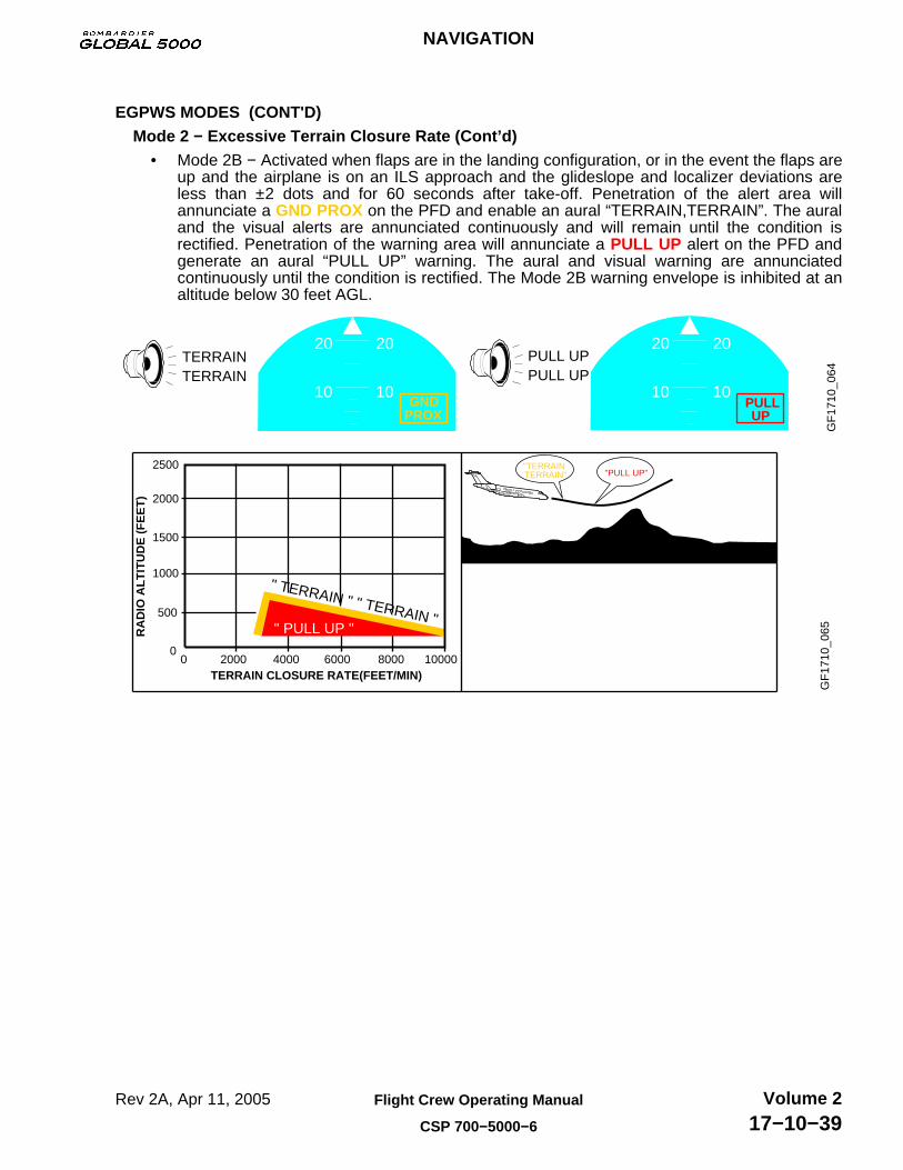
• Mode 2B − Activated when flaps are in the landing configuration, or in the event the flaps areup and the airplane is on an ILS approach and the glideslope and localizer deviations areless than ±2 dots and for 60 seconds after take-off. Penetration of the alert area willannunciate a GND PROX on the PFD and enable an aural “TERRAIN,TERRAIN”. The auraland the visual alerts are annunciated continuously and will remain until the condition isrectified. Penetration of the warning area will annunciate a PULL UP alert on the PFD andgenerate an aural “PULL UP” warning. The aural and visual warning are annunciatedcontinuously until the condition is rectified. The Mode 2B warning envelope is inhibited at analtitude below 30 feet AGL.
PULL UPTERRAINTERRAIN
PULL UP
GF
1710
_064
20
GNDPROX
10PULL UP
20
10
20
10
20
10
"TERRAINTERRAIN" "PULL UP"
2500
2000
1500
1000
500
00 2000
RA
DIO
ALT
ITU
DE
(F
EE
T)
TERRAIN CLOSURE RATE(FEET/MIN)
GF
1710
_065
4000 6000 8000 10000
" PULL UP "
" TERRAIN " " TERRAIN "
NAVIGATION
Rev 2A, Apr 11, 2005 Flight Crew Operating Manual
CSP 700−5000−6
Volume 217−10−39
EGPWS MODES (CONT'D)Mode 3 − Altitude Loss After Take-off
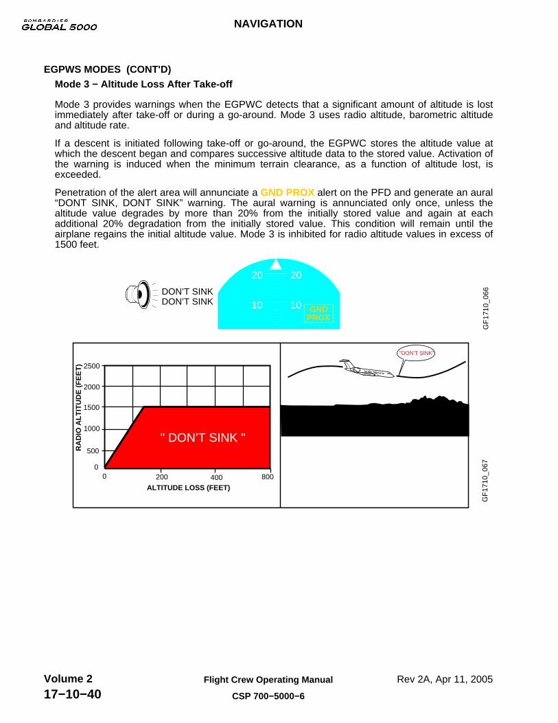
Mode 3 provides warnings when the EGPWC detects that a significant amount of altitude is lostimmediately after take-off or during a go-around. Mode 3 uses radio altitude, barometric altitudeand altitude rate.
If a descent is initiated following take-off or go-around, the EGPWC stores the altitude value atwhich the descent began and compares successive altitude data to the stored value. Activation ofthe warning is induced when the minimum terrain clearance, as a function of altitude lost, isexceeded.
Penetration of the alert area will annunciate a GND PROX alert on the PFD and generate an aural“DONT SINK, DONT SINK” warning. The aural warning is annunciated only once, unless thealtitude value degrades by more than 20% from the initially stored value and again at eachadditional 20% degradation from the initially stored value. This condition will remain until theairplane regains the initial altitude value. Mode 3 is inhibited for radio altitude values in excess of1500 feet.
DON’T SINKDON’T SINK
20
10
GF
1710
_066
GNDPROX
20
10
500
1000
1500
2000
2500
RA
DIO
ALT
ITU
DE
(F
EE
T)
ALTITUDE LOSS (FEET)200 400 8000
0
"DON’T SINK"
GF
1710
_067
" DON’T SINK "
NAVIGATION
Rev 2A, Apr 11, 2005Flight Crew Operating Manual
CSP 700−5000−6
Volume 217−10−40

EGPWS MODES (CONT'D)Mode 4 − Unsafe Terrain Clearance
Mode 4 provides alerts and warnings for insufficient terrain clearance based on airplane phase offlight and airspeed. Mode 4 requires radio altitude, computed airspeed, gear position and flapposition inputs. The alert and warning envelopes are based on minimum allowable terrainclearance as a function of computed airspeed.
Mode 4 is divided into 3 sub-modes: Mode 4A, Mode 4B and Mode 4C.
• Mode 4A − Active when the airplane is in cruise or approach phase of flight and the landinggear is not in the landing position. The alert envelope for Mode 4A begins at 30 feet AGLand extends vertically to an altitude of 500 feet AGL. Penetration of the alert area, above190 knots, the upper boundary increases with airspeed to a maximum of 1000 feet radioaltitude at 250 knots or more and will annunciate a GND PROX message and generate acontinuous aural “TOO LOW TERRAIN” warning. Penetration of the alert area, below 190knots, will annunciate a GND PROX alert on the PFD and generate an aural ”TOO LOWGEAR” warning. The aural and visual remain until the airplane exits the envelope.
TOO LOW GEAR
TOO LOWTERRAIN
20
10
20
10
GF
1710
_068
GNDPROX
GNDPROX
20
10
20
10
GF
1710
_069
"TOO LOW TERRAIN"
AIRCRAFT SLOWED TO LESS THAN 190 KNOTS
UNSAFE TERRAIN CLEARANCEGEAR UP, FLAPS UP
MIN
TE
RR
AIN
CLE
AR
AN
CE
(F
EE
T)
150014001300120011001000900800700600500400300200100
400COMPUTED AIRSPEED (KNOTS)
RUNWAY
TOO LOW TERRAINWARNING AREA
TOO LOW GEARWARNING AREA
00 100 200 300
" TOO LOW TERRAIN " " TOO LOW GEAR "
NAVIGATION
Rev 2A, Apr 11, 2005 Flight Crew Operating Manual
CSP 700−5000−6
Volume 217−10−41
EGPWS MODES (CONT'D)Mode 4 − Unsafe Terrain Clearance (Cont’d)
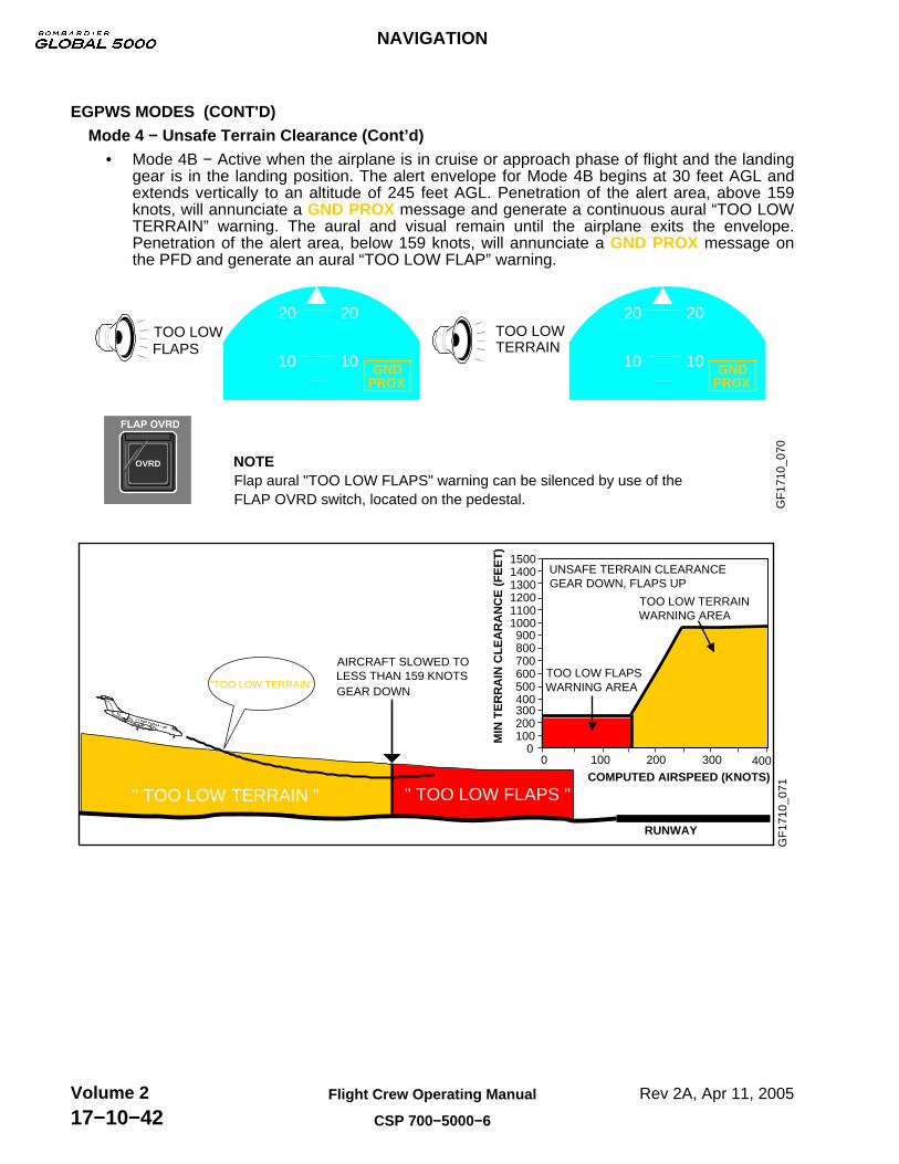
• Mode 4B − Active when the airplane is in cruise or approach phase of flight and the landinggear is in the landing position. The alert envelope for Mode 4B begins at 30 feet AGL andextends vertically to an altitude of 245 feet AGL. Penetration of the alert area, above 159knots, will annunciate a GND PROX message and generate a continuous aural “TOO LOWTERRAIN” warning. The aural and visual remain until the airplane exits the envelope.Penetration of the alert area, below 159 knots, will annunciate a GND PROX message onthe PFD and generate an aural “TOO LOW FLAP” warning.
NOTEFlap aural "TOO LOW FLAPS" warning can be silenced by use of theFLAP OVRD switch, located on the pedestal. G
F17
10_0
70
TOO LOWTERRAIN
TOO LOWFLAPS
20
10
20
10GNDPROX
GNDPROX
20
10
20
10
OVRD
GF
1710
_071
"TOO LOW TERRAIN"
AIRCRAFT SLOWED TO LESS THAN 159 KNOTS
UNSAFE TERRAIN CLEARANCEGEAR DOWN, FLAPS UP
TOO LOW TERRAIN
TOO LOW FLAPSWARNING AREA
MIN
TE
RR
AIN
CLE
AR
AN
CE
(F
EE
T)
150014001300120011001000900800700600500400300200100
00 100 200 300 400
COMPUTED AIRSPEED (KNOTS)
RUNWAY
GEAR DOWN
" TOO LOW TERRAIN " " TOO LOW FLAPS "
WARNING AREA
NAVIGATION
Rev 2A, Apr 11, 2005Flight Crew Operating Manual
CSP 700−5000−6
Volume 217−10−42

EGPWS MODES (CONT'D)Mode 4 − Unsafe Terrain Clearance (Cont’d)
• Mode 4C is based on a minimum terrain clearance, or floor, that increases with radio altitudeduring take-off. Any decrease in altitude below minimum terrain clearance will annunciate aGND PROX message and generate an aural “TOO LOW TERRAIN” warning.
TOO LOWTERRAIN
20
10
GF
1710
_072
GNDPROX
20
10
GF
1710
_073
0 400 800 1200 1600 2000 2400 2800
UNSAFE TERRAIN CLEARANCEGEAR DOWN, FLAPS UP1500 FPM CLIMB RATE
TAKE-OFF OVER FLAT TERRAINOR WATER
WARNING AREA (>250 KNOTS)
WARNING AREA (<190 KNOTS)
RADIO ALTITUDE (FEET)
"TOO LOW TERRAIN"
"TOO LOW TERRAIN"
2800260024002200200018001600140012001000800600400200
0
3000
MIN
TE
RR
AIN
CLE
AR
AN
CE
(F
EE
T)
NAVIGATION
Rev 2A, Apr 11, 2005 Flight Crew Operating Manual
CSP 700−5000−6
Volume 217−10−43

EGPWS MODES (CONT'D)Mode 5 − Descent Below Glideslope
Mode 5 provides alerts and warnings when the airplane descends below the glideslope on an ILSapproach. The alerts and warnings are annunciated in two distinct tones, depending on theposition of the airplane on the glideslope.
When the airplane descends more than 1.3 dots (but not more than 2 dots) below the glideslope, asoft (6dB) aural “GLIDESLOPE” is generated. If the airplane continues to descend and deviatesmore than 2 dots below the glideslope, an aural “GLIDESLOPE” warning is generated at the samevolume level as all other warnings. A GND PROX message is annunciated on the PFD. The auraland visual alerts and warnings are continuously annunciated until the airplane exits the alertenvelope.
GLIDESLOPE (SOFT)
GLIDESLOPE
NOTEThe "GLIDESLOPE" aural warning can be muted, using the GS WARNswitch on the engine control panel, located on the pedestal.
20
10
20
10
GF
1710
_074
GNDPROX
GNDPROX
20
10
20
10
MUTED
GF
1710
_075M
IN T
ER
RA
IN C
LEA
RA
NC
E (
FE
ET
)
GLIDESLOPE DEVIATION (DOTS FLY UP)
SOFT"GLIDESLOPE"
HARD"GLIDESLOPE"
0
1000900800700600500400300200100
0 1 2 3 5
MODE 5 BELOW GLIDESLOPE ALERTGEAR DOWN
RUNWAY
GLIDESLOPEBEAMCENTRE
HARD ALERT
SOFT ALERT AREA
AREA
HARD ALERT AREA
SOFT ALERT AREA
Mode 6 − Callouts
Mode 6 provides the following advisory alerts: transition through approach minimums, altitudecallouts on approach and excessive bank angles.
• Transition through the preset approach minimums, (APPROACHING DECISION HEIGHT orAPPROACHING MINIMUMS), generates an aural “MINIMUMS, MINIMUMS” warning. Thewarning function is enabled between 1000 feet and 10 feet radio altitude for DH minimumsand when the corrected altitude exceeds the MDA value by 200 feet. The landing gear mustbe down for activation of the warning.
NAVIGATION
Rev 2A, Apr 11, 2005Flight Crew Operating Manual
CSP 700−5000−6
Volume 217−10−44
EGPWS MODES (CONT'D)Mode 6 − Callouts (Cont’d)
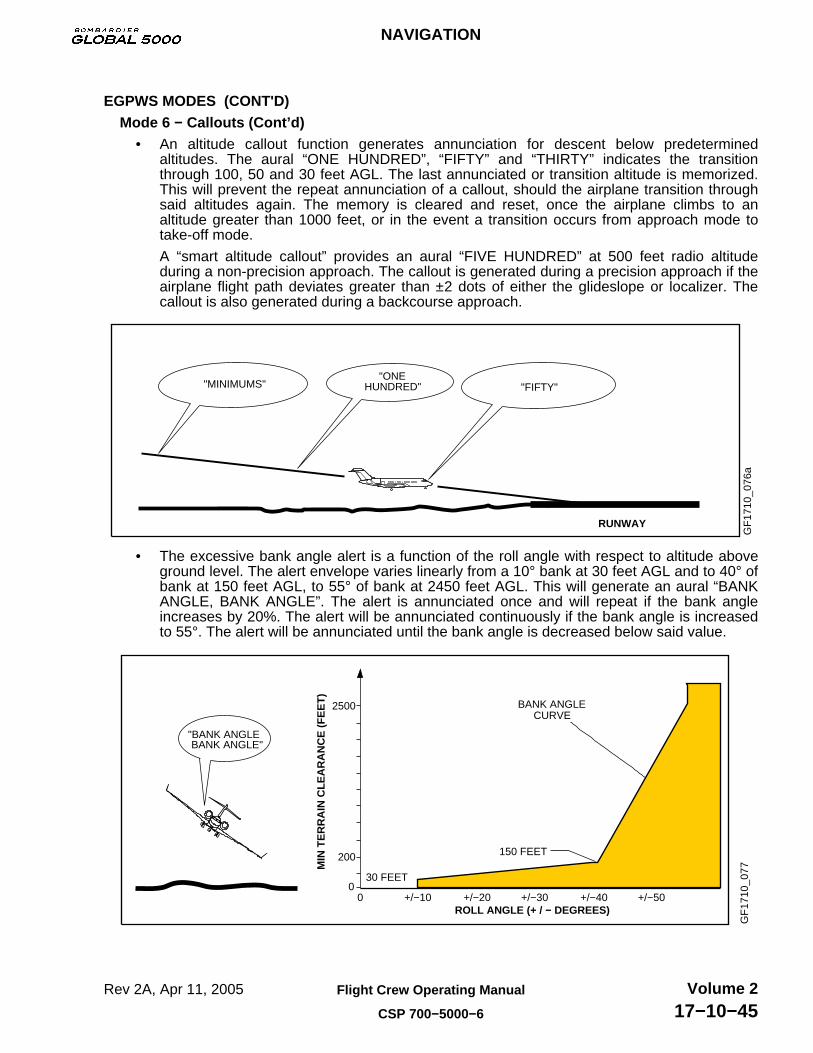
• An altitude callout function generates annunciation for descent below predeterminedaltitudes. The aural “ONE HUNDRED”, “FIFTY” and “THIRTY” indicates the transitionthrough 100, 50 and 30 feet AGL. The last annunciated or transition altitude is memorized.This will prevent the repeat annunciation of a callout, should the airplane transition throughsaid altitudes again. The memory is cleared and reset, once the airplane climbs to analtitude greater than 1000 feet, or in the event a transition occurs from approach mode totake-off mode.
A “smart altitude callout” provides an aural “FIVE HUNDRED” at 500 feet radio altitudeduring a non-precision approach. The callout is generated during a precision approach if theairplane flight path deviates greater than ±2 dots of either the glideslope or localizer. Thecallout is also generated during a backcourse approach.
RUNWAY
GF
1710
_076
a
"ONEHUNDRED""MINIMUMS" "FIFTY"
• The excessive bank angle alert is a function of the roll angle with respect to altitude aboveground level. The alert envelope varies linearly from a 10° bank at 30 feet AGL and to 40° ofbank at 150 feet AGL, to 55° of bank at 2450 feet AGL. This will generate an aural “BANKANGLE, BANK ANGLE”. The alert is annunciated once and will repeat if the bank angleincreases by 20%. The alert will be annunciated continuously if the bank angle is increasedto 55°. The alert will be annunciated until the bank angle is decreased below said value.
GF
1710
_077
+/−50
"BANK ANGLEBANK ANGLE"
MIN
TE
RR
AIN
CLE
AR
AN
CE
(F
EE
T)
ROLL ANGLE (+ / − DEGREES)
0
2500
200
0 +/−10 +/−20 +/−30 +/−40
150 FEET
30 FEET
BANK ANGLECURVE
NAVIGATION
Rev 2A, Apr 11, 2005 Flight Crew Operating Manual
CSP 700−5000−6
Volume 217−10−45
EGPWS MODES (CONT'D)Mode 7 − Windshear Warning
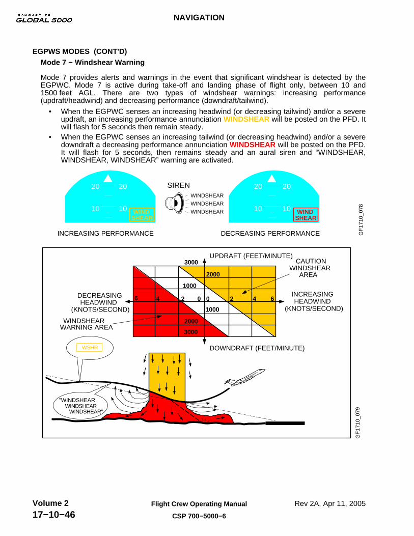
Mode 7 provides alerts and warnings in the event that significant windshear is detected by theEGPWC. Mode 7 is active during take-off and landing phase of flight only, between 10 and1500 feet AGL. There are two types of windshear warnings: increasing performance(updraft/headwind) and decreasing performance (downdraft/tailwind).
• When the EGPWC senses an increasing headwind (or decreasing tailwind) and/or a severeupdraft, an increasing performance annunciation WINDSHEAR will be posted on the PFD. Itwill flash for 5 seconds then remain steady.
• When the EGPWC senses an increasing tailwind (or decreasing headwind) and/or a severedowndraft a decreasing performance annunciation WINDSHEAR will be posted on the PFD.It will flash for 5 seconds, then remains steady and an aural siren and “WINDSHEAR,WINDSHEAR, WINDSHEAR” warning are activated.
WINDSHEAR
WINDSHEAR
WINDSHEAR
20
10 WINDSHEAR
20
10 WINDSHEAR
SIREN
INCREASING PERFORMANCE DECREASING PERFORMANCE GF
1710
_078
20
10
20
10
"WINDSHEARWINDSHEAR
WINDSHEAR"
DOWNDRAFT (FEET/MINUTE)
CAUTIONWINDSHEAR
WINDSHEARWARNING AREA
WSHR
DECREASINGHEADWIND
(KNOTS/SECOND)
INCREASINGHEADWIND
(KNOTS/SECOND)
GF
1710
_079
UPDRAFT (FEET/MINUTE)
AREA
3000
1000
2000
1000
2000
3000
6 4 2 0 0 2 4 6
NAVIGATION
Rev 2A, Apr 11, 2005Flight Crew Operating Manual
CSP 700−5000−6
Volume 217−10−46

EGPWS MODES (CONT'D)Windshear Flight Director Mode Annunciations
The WSHR mode can only be activated when a windshear warning is present. The mode can beactivated by depressing either TOGA button on the thrust levers or by pushing either thrust leverbeyond 37 degrees. If however the airplane is already in TOGA mode, or has either thrust leverbeyond 37 degrees at the point at which the windshear warning is posted, the mode setsautomatically.
The WSHR mode cannot be cancelled when a windshear warning persists. Any selection of theFD or AP engage buttons are ignored but yaw damper function is unaffected. Once the windshearwarning has cleared, WSHR mode can be cancelled by any selection of FD or engagement of AP.
A WSHR mode annunciation is displayed on the vertical mode and a ROL mode annunciation isdisplayed on the lateral mode.
GF
1710
_080
WINDSHEAR
ROL160 3 000
2020
WSHRAP1
WINDSHEAR
180
170
160
150145
6
1500
1000
WINDSHEARWINDSHEAR
ROL WSHRAP1
TOGA Buttons
Windshear Escape Guidance
The windshear mode will provide windshear escape guidance consisting of lateral and verticalmodes as follows:
• Vertical guidance will provide optimal escape guidance.• Lateral guidance will be provided to maintain wings level.
A pitch limit indicator and windshear annunciation are displayed on both PFDs, during anincreasing or decreasing performance windshear. The pitch limit indicator will differ depending onselection of Single Cue or Cross Pointer.
GF
1710
_081WINDSHEAR
WINDSHEAR
WINDSHEAR
20
10SIREN
20
10
CROSS POINTERSINGLE CUE
PITCH LIMIT INDICATOR
WINDSHEAR
WINDSHEAR
20
10
20
10
Windshear escape guidance is designed to allow the airplane to accelerate through the windshearwhere airplane performance permits. Where airplane performance does not permit, the WSHRmode will prevent the airplane from descending. The WSHR mode will command a descent if theairplane approaches the stall warning point, to prevent the airplane from stalling.
For an increasing performance windshear, guidance will be given to maintain a slightly positiveflight path angle (1.5 degrees) until airspeed (CAS) reaches 20 knots above the CAS recordedwhen the windshear mode was set. Guidance is then provided to climb the airplane at that speed.
NAVIGATION
Rev 2A, Apr 11, 2005 Flight Crew Operating Manual
CSP 700−5000−6
Volume 217−10−47

EGPWS MODES (CONT'D)Windshear Escape Guidance (Cont’d)
For a decreasing performance windshear, guidance will be provided to maintain a slightly positiveflight path angle (1.5 degrees) until the AOA increases to within 2 degrees of stick shaker firingangle. The airplane will then be allowed to descend maintaining this margin to shaker. Between400 and 10 feet (RAD ALT) margin to stick shaker will be reduced linearly to provide guidance atstick shaker AOA.
Terrain Awareness Alerting
The terrain alerting function computes minimum terrain clearance envelopes for areas along theflightpath of the airplane. The function uses airspeed and flightpath angle data in conjunction witha database containing worldwide topographical relief information in grid format. The databasedoes not account for man-made obstructions except for all known man-made obstacles in Canadaand the United States.
The terrain display is available by pressing “TERR” button on the MFD control panel. Terrain within2000 feet of the airplane altitude is displayed. Terrain will automatically pop up, in MAP mode, onthe MFD at a 10NM range, if there is a terrain threat caution at 60 seconds from impact.
GF
1710
_082
TERR ButtonSelecting TERR button enables terrain displays, (MAP mode only). Automatically deselects WX radar (if selected). Selecting TERR button again will re-enable WX radar (if previously selected).
NAVIGATION
Rev 2A, Apr 11, 2005Flight Crew Operating Manual
CSP 700−5000−6
Volume 217−10−48
EGPWS MODES (CONT'D)Terrain Awareness Alerting (Cont’d)
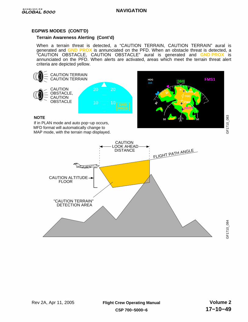
When a terrain threat is detected, a “CAUTION TERRAIN, CAUTION TERRAIN” aural isgenerated and GND PROX is annunciated on the PFD. When an obstacle threat is detected, a“CAUTION OBSTACLE, CAUTION OBSTACLE” aural is generated and GND PROX isannunciated on the PFD. When alerts are activated, areas which meet the terrain threat alertcriteria are depicted yellow.
GF
1710
_083
20
10 GNDPROX
20
10
NOTEIf in PLAN mode and auto pop−up occurs,MFD format will automatically change to
CAUTION TERRAINCAUTION TERRAIN
CAUTIONOBSTACLE,CAUTIONOBSTACLE
MAP mode, with the terrain map displayed.
315FMS1360
30 6
HDG
N
50 50
3
33
KDVT
KPHX 3TOC
KSRP
GF
1710
_084
CAUTION ALTITUDEFLOOR
"CAUTION TERRAIN"DETECTION AREA
CAUTION LOOK AHEAD
DISTANCE
FLIGHT PATH ANGLE
NAVIGATION
Rev 2A, Apr 11, 2005 Flight Crew Operating Manual
CSP 700−5000−6
Volume 217−10−49
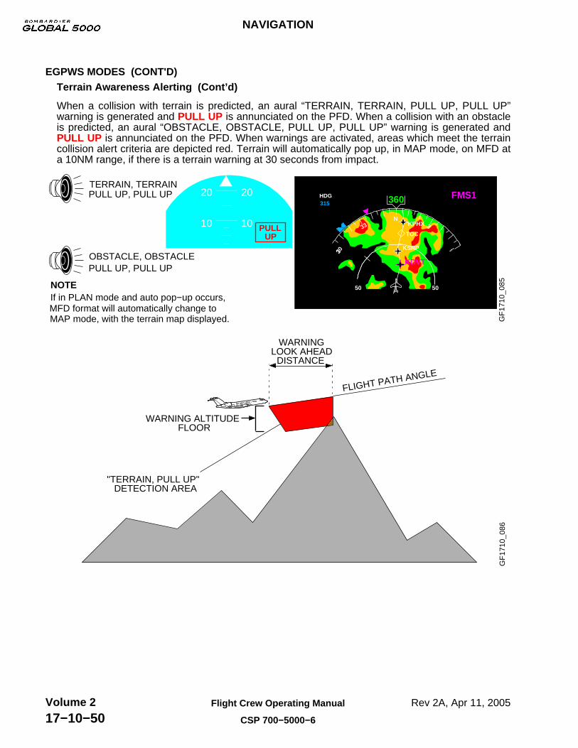
EGPWS MODES (CONT'D)Terrain Awareness Alerting (Cont’d)
When a collision with terrain is predicted, an aural “TERRAIN, TERRAIN, PULL UP, PULL UP”warning is generated and PULL UP is annunciated on the PFD. When a collision with an obstacleis predicted, an aural “OBSTACLE, OBSTACLE, PULL UP, PULL UP” warning is generated andPULL UP is annunciated on the PFD. When warnings are activated, areas which meet the terraincollision alert criteria are depicted red. Terrain will automatically pop up, in MAP mode, on MFD ata 10NM range, if there is a terrain warning at 30 seconds from impact.
GF
1710
_085
20
10 PULLUP
20
10
NOTEIf in PLAN mode and auto pop−up occurs,MFD format will automatically change to
TERRAIN, TERRAINPULL UP, PULL UP
OBSTACLE, OBSTACLE
MAP mode, with the terrain map displayed.
PULL UP, PULL UP
315FMS1360
30 6
HDG
N
50 50
3
33
KDVT
KPHX 3TOC
KSRP
GF
1710
_086
WARNING ALTITUDEFLOOR
"TERRAIN, PULL UP"DETECTION AREA
WARNING LOOK AHEAD
DISTANCE
FLIGHT PATH ANGLE
NAVIGATION
Rev 2A, Apr 11, 2005Flight Crew Operating Manual
CSP 700−5000−6
Volume 217−10−50

EGPWS MODES (CONT'D)Annunciations
All terrain annunciations are displayed on the MFD. The annunciations are as follows:
GF
1710
_087
TERR not selected. TERR: TERR has been selected.
TERR TEST: Indicates a self-test.
TERR FAIL: Indicates internal failure, or loss of communication with EFIS. CNTRL FAIL: Indicates loss of range control for terrain map.TERR N/A: Position Uncertain.
NOTEIn a case where landing at an airport that is not in the database, all TERRAINfunctions can be inhibited, by selecting the TERRAIN switch, located on theoverhead panel.
Terrain sytem selected OFF, using the switch selection on the overhead panel.OFF
KPHXTOC
KSRPKDVT
4000 4000
FL180
SAT
GSPD
−56TATTAS
−40234345
TERR
BLANK:
TERR :
OFF
Terrain Clearance Floor (TCF)
The TCF function supplements the GPWS function by providing an additional terrain clearancealert envelope around airports. The TCF criteria is used to determine alert and warning envelopes.
TCF creates an increasing terrain clearance envelope around the intended airport runway directlyrelated to the distance from the runway. TCF alerts are based on current airplane location, nearestrunway center point position and radio altitude, along with an internal database that includes allworldwide, hard-surfaced runways greater than 3500 feet in length.
Penetration of the alert envelope will generate an aural “TOO LOW TERRAIN” and a GND PROXmessage is displayed on the PFD. The aural alert is repeated twice and again thereafter if theradio altitude value decreases by more than 20% from the altitude at which the initial warning wasissued. The GND PROX message remains displayed until the airplane exits the alert envelope.
GF
1710
_088TOO LOW
TERRAIN
20
10GND
PROX
20
10
GF
1710
_089
DISTANCE TO SELECTED RUNWAY (NM)
12 15
"TOO LOW TERRAIN"
4
RUNWAY
12NM
15NM
4NM
AGL AGL
700400
NAVIGATION
Rev 2A, Apr 11, 2005 Flight Crew Operating Manual
CSP 700−5000−6
Volume 217−10−51

EGPWS SCHEMATIC
GF
1710
_090
ASCB
FMS
FWC
SG
AFCS
FMS
FWC
SG
FMS
FWC
SG
AFCS
IAC 1 IAC 3 IAC 2
A B
DAU 3
TCAS
ENHANCEDGROUND
PROXIMITYWARNING
COMPUTER
"GPWS INSTALLEDCONFIG" DISCRETE
"EGPWS INSTALLED" CONFIG DISCRETE
IRS 1
IRS 2
ADC 1
ADC 2
GPS 1
GPS 2
RAD ALT 1
RAD ALT 2
SPC CHAN ACHAN B
LANDING GEARDOOR CONTROL
ANDINDICATINGSYSTEM
PMAT
AUDIO PANEL1, 2, 3 (if installed)
FLAPOVERRIDE
GLIDESLOPECANCEL
AIRCRAFT
DISCRETE
NOSE GEARDOWNLOCK
GPWS BUS 1
GPWS BUS 2
TCAS AUDIO INHIBIT
TERRAIN PICTURE BUS 1/2
MFD 2MFD 1
NAVIGATION
Rev 2A, Apr 11, 2005Flight Crew Operating Manual
CSP 700−5000−6
Volume 217−10−52
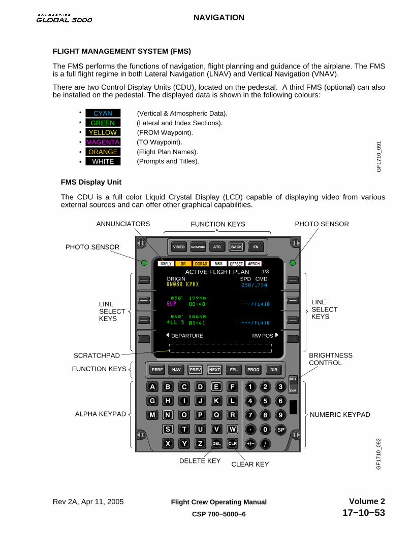
FLIGHT MANAGEMENT SYSTEM (FMS)
The FMS performs the functions of navigation, flight planning and guidance of the airplane. The FMSis a full flight regime in both Lateral Navigation (LNAV) and Vertical Navigation (VNAV).
There are two Control Display Units (CDU), located on the pedestal. A third FMS (optional) can alsobe installed on the pedestal. The displayed data is shown in the following colours:
GF
1710
_091
(Vertical & Atmospheric Data).(Lateral and Index Sections).(FROM Waypoint).(TO Waypoint).
(Flight Plan Names).(Prompts and Titles).
CYANGREEN
MAGENTA
ORANGE
YELLOW
WHITE
FMS Display Unit
The CDU is a full color Liquid Crystal Display (LCD) capable of displaying video from variousexternal sources and can offer other graphical capabilities.
LINE SELECT
BRIGHTNESS CONTROL
ALPHA KEYPAD NUMERIC KEYPAD
CLEAR KEYDELETE KEY
FUNCTION KEYS PHOTO SENSOR
PHOTO SENSOR
ANNUNCIATORS
GF
1710
_092
KEYS
LINE SELECT KEYS
SCRATCHPAD
FUNCTION KEYS
VIDEO GRAPHIC ATC BACK FN
SP
+/−
BRT
DIM
1/3ORIGIN SPD CMD
DEPARTURE RW POS
ACTIVE FLIGHT PLAN
NAVIGATION
Rev 2A, Apr 11, 2005 Flight Crew Operating Manual
CSP 700−5000−6
Volume 217−10−53

FLIGHT MANAGEMENT SYSTEM (FMS) (CONT'D)Annunciators
There are six annunciators located at the top of the Control Display Unit (CDU) LCD panel. Theannunciators are left justified. White annunciators indicates an advisory annunciation, amberannunciators indicate an alerting annunciation.
Annunciators
GF
1710
_094VIDEO GRAPHIC ATC BACK FN
1/3ACTIVE FLIGHT PLANORIGIN SPD CMD
The annunciators are:
(Display) − is lit when the CDU displays:
• A flight plan page other than the first page of the active flight plan.• A stored flight plan page.• Any of the review pages for SIDs and STARs/approaches.• A CHANGE ACTIVE LEG message.• Defining an INTERCEPT waypoint on the active leg.
(Dead Reckoning) − is lit when operating in the DR mode for longer than 2 minutes. The DRmode is defined as the loss of radio updating and all other position sensors.
DGRAD (Degraded) − is lit when the FMS cannot guarantee the position accuracy for the presentphase of flight due to sensor availability. If the DR annunciator is lit when DGRAD is lit, DGRADannunciator goes out. The annunciator is lit if both of the following conditions are valid:
• The sensors being used to navigate are not approved for the current phase of flight.• A non-precision instrument approach (NDB, NDB/DME, VOR, VOR/DME, GPS, RNAV, or
DME/DME) is selected. If no approach, or an ILS, LOC, LOC-BC, LDA, SDF, or MLSapproach is selected, the APRCH annunciator does not light.
NAVIGATION
Rev 2A, Apr 11, 2005Flight Crew Operating Manual
CSP 700−5000−6
Volume 217−10−54

FLIGHT MANAGEMENT SYSTEM (FMS) (CONT'D)Annunciators (Cont’d)
Flight Phase Approved sensors (Navigation Mode)
GPS DME/DME VOR/DME IRS
Departure orTerminal
X X X (see note)
Enroute X X X X
Oceanic X X X X
VOR/DME orVOR Approach
X X X −
GPS Approach X − − −
NBD Approach X X − −
NOTE:The FMS uses IRS as the navigation mode for a limited time in these phases of flight. Thetime is determined in the FMS by estimating when the drift rate error of the IRS exceeds 1.7 NMfor departure and terminal operations.
MSG (Message) − is lit when a message is displayed in the scratchpad. Messages are displayedin the CDU scratchpad to inform or alert the pilot as to the system status. The annunciator goesout after the message(s) has been cleared from the scratchpad. For a list of FMS messages, referto the Flight Management System Pilot’s Guide. Messages are divided into two groups:
• Advisory messages − Contains information that is useful to the pilot. Areusually the result of a pilot action on the CDU.
INVALID ENTRY
• Alerting messages − Alert the pilot to FMS status.
COMPARE FMS POSITIONS
If a graphic or video is currently displayed on the CDU−820 and a message appears, the CDUdisplay will immediately return to the FMS page and a message will be shown in the scratchpad.
OFFSET (Offset) − is lit when a lateral offset has been entered on PROGRESS page. The annunciatorgoes out when the offset is removed.
APRCH (Approach) − indicates that FMS is in approach mode of operation. In this mode, the EFISdeviation sensitivity and FMS tacking gains are increased. APRCH is lit when the followingconditions are valid:
• FMS is selected navigation source on EFIS.• A non-precision instrument approach is selected• The airplane position is between 2 NM outside the Final Approach Fix (FAF) and the Missed
Approach Point (MAP).• The DGRAD annunciator must not be displayed.• The FMS must be using approved sensors for the selected approach procedure (VOR, VOR
DME, NDB, GPS).
NAVIGATION
Rev 2A, Apr 11, 2005 Flight Crew Operating Manual
CSP 700−5000−6
Volume 217−10−55

FLIGHT MANAGEMENT SYSTEM (FMS) (CONT'D)Brightness Control
Both the manual and automatic (photo sensor) brightness controls are used to increase ordecrease the display brightness. When selected manually, a bright/dim bar is displayed in thescratchpad. The bright/dim bar level is controlled by pressing BRT or DIM. After the adjustment ismade, the photo sensors monitor the ambient light and maintain the brightness level over variouslighting conditions.
GF
1710
_099
VIDEO GRAPHIC ATC BACK FN
BRT
DIM
PERF INIT
PERF PLAN
CLIMB
DESCENT
PERF DATA
TAKEOFF
CRUISE
LANDING
PERF INDEX 1/2
BRIGHT/DIMBAR LEVEL BRIGHTNESS
CONTROL (MANUAL)
PHOTO SENSOR(AUTOMATIC)
PHOTO SENSOR(AUTOMATIC)
Line Select Keys
Data is selected to a line from the scratchpad or vice-versa using the line select keys. These keysare identified from top to bottom as 1L through 4L on the left side and 1R through 4R on the rightside.
GF
1710
_101
VIDEO GRAPHIC ATC BACK FN
BRT
DIM
1/3ORIGIN SPD CMD
DEPARTURE RW POS
ACTIVE FLIGHT PLAN
LINE SELECT KEYS
1R2R
3R
4R
1L2L
3L
4L
LINE SELECT KEYS
SCRATCHPAD
NAVIGATION
Rev 2A, Apr 11, 2005Flight Crew Operating Manual
CSP 700−5000−6
Volume 217−10−56

FLIGHT MANAGEMENT SYSTEM (FMS) (CONT'D)Line Select Keys (Cont’d)
The line select keys are used for:
• Direct Access Prompts/Function selects − In the case of a NAV or PERF index display (seefunction keys), the line select keys are used to select functions from the index. In displaysother than index, keys 4L and 4R are primarily used for direct access to other functions inthe FMS. The functions that are most likely to be accessed from the present page andphase of flight are displayed as prompts.
• Transfer Line Data to Scratchpad − If the scratchpad is empty, pushing a line select keytransfers the respective line data to the scratchpad.
• Transfer of Scratchpad Data to Line Fields − Once data has been entered into thescratchpad, either through line selection or manual keyboard entry, it can be selected to anyof the allowable line select fields on a page.
NAVIGATION
Rev 2A, Apr 11, 2005 Flight Crew Operating Manual
CSP 700−5000−6
Volume 217−10−57

FLIGHT MANAGEMENT SYSTEM (FMS) (CONT'D)Legend
The following conventions are used in this section to indicate actions, results and sequences:
GF
1710
_103
240 / 3000 2400
10JUL97
2
PUSH A FUNCTION KEY OR LINE KEYThe finger indicates to push a function or line key. Keys shownunder finger, are keys to push.
SEQUENCE OF ACTIONSCircled numbers show sequences for graphic images and their relationship to written steps of text. Must be followed in sequenceto achieve desired results.
RESULT OF ACTIONPoints to expected result of an action. Unexpected results mayindicate incorrect key inputs.
SEQUENCE OF KEYS TO PUSHIndicates that a series of key inputs are required. Push data keysfrom left to right, top to bottom.
SPECIFIC DISPLAY RESULT (BOXED AREA)Indicates where to look for expected result.
SPECIFIC DISPLAY RESULT−SCRATCHPAD ENTRY(BRACKETS)Locates the scratchpad display line on a figure.
CLEAR KEYUsed to clear data from scratchpad.
For more information, refer to the Flight Management System Pilot’s Guide.
NOTE
Function Keys
The seven function keys access primary functions, menus and paging.
NAVIGATION
Rev 2A, Apr 11, 2005Flight Crew Operating Manual
CSP 700−5000−6
Volume 217−10−58

FLIGHT MANAGEMENT SYSTEM (FMS) (CONT'D)Function Keys (Cont’d)
The function keys are as follows:
• (Performance) Key − Pushing the PERF function key displays page 1 of theperformance index. Any functions can be selected by pushing the respective line select key.To view the next page of PERF INDEX push NEXT function key.
GF
1710
_106
PERF INDEX 1/2
PERF INIT PERF DATA
PERF PLAN TAKEOFF
CLIMB CRUISE
DESCENT LANDING THRUST MGT
PERF INDEX 2/2
INIT <− − −WHAT IF− − −>DATA
INIT <− −STORED FPL− −>
FUEL MGT S.E. RANGE
DATA
• (Navigation) Key − Pushing the NAV function key displays page 1 of the navigationindex. Any functions can be selected by pushing the respective line select key. To view thenext page of NAV INDEX push NEXT function key.
GF
1710
_108
NAV INDEX 1/2
FPL LIST FPL SEL
WPT LIST DATA BASE
DEPARTURE ARRIVAL
POS SENSORS TUNE
NAV INDEX 2/2
CONVERSION PATTERNS
IDENT MAINTENANCE
POS INIT CROSS PTS
DATA LOAD FLT SUM
• (Previous and Next) Paging Keys − The specific page and number of pages 2/2
in a particular function or menu display are shown in the upper right hand corner of thedisplay. Page changes are made by pushing the PREV (previous) and NEXT keys. The keyscan be held down for repeated page changing.
NAVIGATION
Rev 3, Apr 25, 2005 Flight Crew Operating Manual
CSP 700−5000−6
Volume 217−10−59

FLIGHT MANAGEMENT SYSTEM (FMS) (CONT'D)Function Keys (Cont’d)
• (Flight Plan) Key − Pushing the FPL key displays the first page of the active flightplan, even if another page of the active flight plan is being displayed. If there is no flight planentered, the pilot can manually create a flight plan, select a stored flight plan, load a flightplan from a disk and/or create a stored flight plan.
GF
1710
_111
KICT − KORL FPL 3/3
ORL 00 + 19 − − − −
KORL 00 + 00 0110 034° .2NM
KORLDEST
PATTERN FPL SEL
120° 115NM
KICT − KORL FPL 1/3
KICT 998/02 + 47 @ 359ORIGIN DIST/ETE GS
MEM 01 + 06 − − − − 104° 392NM
VUZ 00 + 29 − − − − 115° 174NM
PATTERN FPL SEL
KICT − KORL FPL 2/3
MGM 00 + 15 − − − −
TLH 00 + 24 − − − − 132° 141NM
TLH84 00 + 14 − − − − 127° 84.1NM
PATTERN FPL SEL
159° 91.7NM
J20. ORL
• (Progress) Key− Pushing the PROG key displays the current status of the flight.There are three progress pages that report progress along the flight plan. These pagessummarize important flight parameters and the airplane’s relationship to the flight plan. Thefirst progress page displays estimated time enroute (ETE), distance to and fuel projection forthe TO waypoint and destination. It also displays the current NAV mode, the number of longrange NAVs used and the navaids that are presently tuned for radio updating.
GF
1710
_113
PROGRESS 1/3
NAV 1 <− − −SELECT− − −> NAV 2
MEM 392.0 01 + 06 10.0
KORL 998 02 + 47 22.0 DEST
A MEM 117.50 A VUZ 114.40 DME/DME LRN = 3 USED
TO DIST ETE FUEL
NAVIGATION
Rev 3, Apr 25, 2005Flight Crew Operating Manual
CSP 700−5000−6
Volume 217−10−60

FLIGHT MANAGEMENT SYSTEM (FMS) (CONT'D)Function Keys (Cont’d)
• The second progress page reflects changes based on inputs to the VNAV FMS function.The speed/altitude command (SPD/ALT CMD) reflects the current command ofspeed/altitude that the FMS is sending to the flight guidance computer. If there is nocommand, the line is titled but blank. The 1R line select displays the expected vertical speedwhen a path has been defined in VNAV.
GF
1710
_114
PROGRESS 2/3
AIR DATA FLT SUM
240 / 3000 2400
151.5 NM / 00+ 23 20000 TOD GROSS WT
SPD/ALT CMD VS@ TOD
TOC FUEL QTY
970 NM / 02+ 25 70,600
• The third progress page displays cross track error (XTK ERROR), lateral offset, current trackand heading in magnetic or true, current wind in vector form and component form, drift angleand ground speed.
GF
1710
_115
PROGRESS 3/3
AIR DATA FLT SUM
L 0.01 NM − − − . − NM
274° 4° 270° WIND − −> GS
XTK ERROR OFFSET
080 T / 57 20 20 423
TRACK DRIFT HDG
• The AIR DATA page displays the values for the on-side ADC. If the on-side ADC fails, theinformation comes from the off-side ADC. The ADC source is displayed on the title.
• The Flight Summary FLT SUM displays flight information, fuel used, average TAS/GS andtotal distance both air and ground.
GF
1710
_116
AIR DATA 1 1/1
PROGRESS 3
21950 21942 1240 SAT ISA DEV TAT
CAS TAS MACH
−27° +2° C 5° C
PRES < − ALT − > BARO VS 300 412 .66
FLIGHT SUMMARY 1/1
PROGRESS 3
1220Z 02+ 02 1422Z
7590 430/420 AIR <− − − DIST − − −> GROUND
T/O ENROUTE LAND
874NM 853NM
FUEL USED AVG TAS/GS
NAVIGATION
Rev 2A, Apr 11, 2005 Flight Crew Operating Manual
CSP 700−5000−6
Volume 217−10−61

FLIGHT MANAGEMENT SYSTEM (FMS) (CONT'D)Function Keys (Cont’d)
• (Direct-to/pattern/intercept) Key − Pushing the DIR function key inserts DIRECT,PATTERN and INTERCEPT prompts on the ACTIVE FLT PLAN pages. If other than anactive flight plan page is displayed when pushing the button, the first page of the flight planis displayed. If the active flight plan is already displayed, it will remain on the current page ofthe flight plan.− DIRECT − The FMS DIRECT-TO function can either be lateral or vertical. The left line
select keys are used for lateral and the right line select keys are used for verticaldirect-to. Lateral DIRECT-TO computes the turn and the course from the end of theturn. If the direct-to waypoint is in the flight plan, pushing the line select key next to thedirect-to waypoint engages the direct-to. A direct-to course is calculated and theairplane begins turning for the waypoint. Vertical DIRECT-TO is connected to analtitude constraint at a waypoint in the flight plan. The altitude constraint must be in theflight plan before the vertical direct-to is done. Vertical DIRECT-TO can be used forclimbs and descents. The airplane does not respond to the vertical DIRECT-TO unlessthe altitude selector is properly set above for climbs and below for descents.
GF
1710
_118
KICT − KORL FPL 2/3
MGM 300/ .75 M
TLH 00 + 24 .88 / FL 350 132° 141NM
TLH84 00 + 14 .88 / FL 350 127° 84.1NM
PATTERN INTERCEPT
− − − − − DIRECT SPD CMD
− PATTERNS − The PATTERNS prompt is used to start the pattern definition or reviewprocedures. PATTERNS can also be selected from the NAV INDEX. The followingpatterns are available: HOLD, PROCEDURE TURN, FLYOVER, ORBIT and RADIAL.
GF
1710
_119
PATTERNS 1/1
REVIEW
HOLD PCDR TURN
FLY OVER ORBIT
RADIAL
− INTERCEPT − INTERCEPT is used to define an intercept waypoint inserted in the flightplan between two other waypoints. The crossing of these two courses is the interceptwaypoint.
GF
1710
_120
INTERCEPT 1/1
CLEAR
− − − ° RAD / CRS OR HDG SEL
− − − ° RAD OR CRS − − − TOD PGS
FROM DRK
NAVIGATION
Rev 2A, Apr 11, 2005Flight Crew Operating Manual
CSP 700−5000−6
Volume 217−10−62
FLIGHT MANAGEMENT SYSTEM (FMS) (CONT'D)Function Keys (Cont’d)
• VIDEO Key (CDU−820 only) − Depending on installation, pressing the VIDEO function keyresults in the following:− The scratchpad message VIDEO NOT AVAILABLE will be displayed if there is no
external video input to the or if access is externally selectable.− The LCD will display a video signal if one video input is available. If multiple video
inputs are available but selectable externally to the CDU, the LCD will display theexternally selected video input.
− If more than one video input is available and video selection is internal to the CDU, theVIDEO INDEX page will be displayed.
If a video input is being displayed, selection of other function keys (PERF, NAV, FPL,PROG, DIR) will return the display to normal FMS operation.
NOTE
If an annunciator and/or scratchpad message is displayed whileviewing a video input, the display will return to the page shownbefore the VIDEO key was pressed.
• GRAPHIC Key (CDU−820 only) − Depending on installation, pressing the GRAPHICfunction key results in the following:− The scratchpad message GRAPHIC NOT AVAILABLE will be displayed if there is no
external video input to the or if access is externally selectable.− If a graphic input is available and access is internal to the CDU, the GRAPHIC INDEX
page will be displayed.
If a graphic input is being displayed, selection of other function keys (PERF, NAV, FPL,PROG, DIR) will return the display to normal FMS operation.
NOTE
If an annunciator and/or scratchpad message is displayed whileviewing a video input, the display will return to the page shownbefore the GRAPHIC key was pressed.
• ATC (Air Traffic Control) Key (CDU−820 only) − Pressing the ATC function key will displaythe scratchpad message ATC NOT AVAILABLE.
• BACK Key (CDU−820 only) − Pressing the BACK function key will display the scratchpadmessage BACK COMPLETE unless video or graphic input is available. If a video or graphicinput is accessed thought the VIDEO INDEX or GRAPHIC INDEX page, pressing the BACKfunction key will return the display to the VIDEO INDEX or GRAPHIC INDEX page. Pressingthe BACK function key again will return the display to the page shown before the VIDEO orGRAPHIC key was pressed. Pressing the BACK function key a third time will display BACKCOMPLETE in the scratchpad.
• FN (Function) Key (CDU−820 only) − Pressing the FN function key will display thescratchpad message FN NOT AVAILABLE.
Pressing and holding the FN function key for 5 seconds will display the SYSTEM SETUPpage.
NAVIGATION
Rev 2A, Apr 11, 2005 Flight Crew Operating Manual
CSP 700−5000−6
Volume 217−10−63
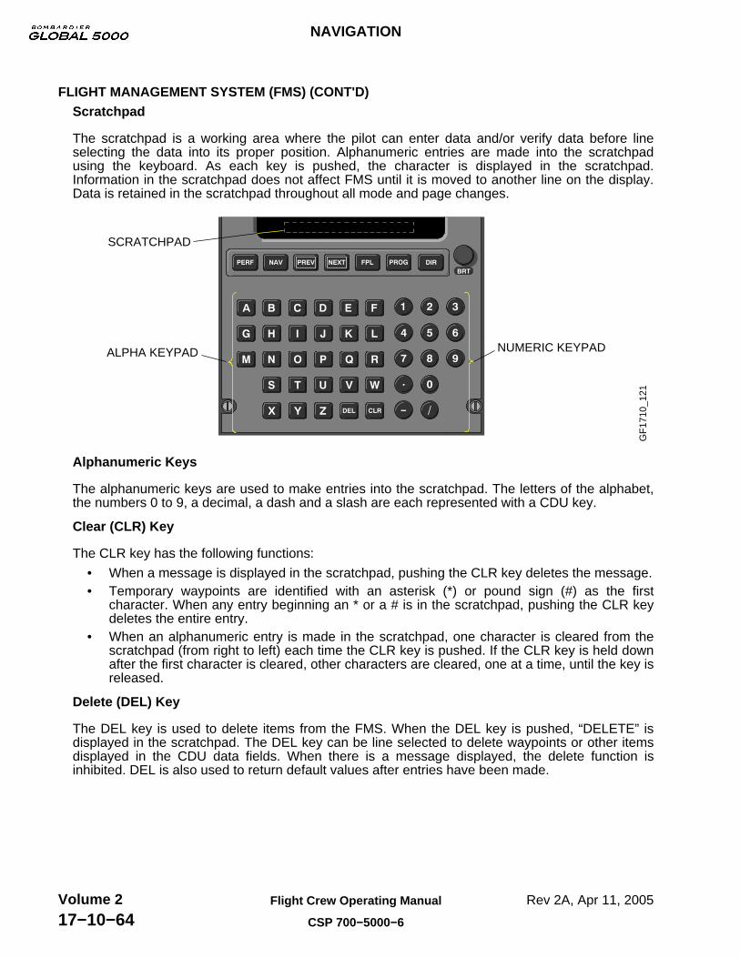
FLIGHT MANAGEMENT SYSTEM (FMS) (CONT'D)Scratchpad
The scratchpad is a working area where the pilot can enter data and/or verify data before lineselecting the data into its proper position. Alphanumeric entries are made into the scratchpadusing the keyboard. As each key is pushed, the character is displayed in the scratchpad.Information in the scratchpad does not affect FMS until it is moved to another line on the display.Data is retained in the scratchpad throughout all mode and page changes.
GF
1710
_121
SCRATCHPAD
ALPHA KEYPAD NUMERIC KEYPAD
Alphanumeric Keys
The alphanumeric keys are used to make entries into the scratchpad. The letters of the alphabet,the numbers 0 to 9, a decimal, a dash and a slash are each represented with a CDU key.
Clear (CLR) Key
The CLR key has the following functions:
• When a message is displayed in the scratchpad, pushing the CLR key deletes the message.• Temporary waypoints are identified with an asterisk (*) or pound sign (#) as the first
character. When any entry beginning an * or a # is in the scratchpad, pushing the CLR keydeletes the entire entry.
• When an alphanumeric entry is made in the scratchpad, one character is cleared from thescratchpad (from right to left) each time the CLR key is pushed. If the CLR key is held downafter the first character is cleared, other characters are cleared, one at a time, until the key isreleased.
Delete (DEL) Key
The DEL key is used to delete items from the FMS. When the DEL key is pushed, “DELETE” isdisplayed in the scratchpad. The DEL key can be line selected to delete waypoints or other itemsdisplayed in the CDU data fields. When there is a message displayed, the delete function isinhibited. DEL is also used to return default values after entries have been made.
NAVIGATION
Rev 2A, Apr 11, 2005Flight Crew Operating Manual
CSP 700−5000−6
Volume 217−10−64

FLIGHT MANAGEMENT SYSTEM (FMS) (CONT'D)FMS Update
To update an FMS (pre-flight), proceed as follows:
The NAV IDENT page is displayed when power is first applied. All parameters should bechecked and/or set.
NOTE
The date and time displayed on this page is synchronized with GPSdate and time. The date and time can be changed only if the GPS isfailed or does not have a valid date/time.
DATE
1. To set the date, enter information in scratchpad using the alphanumerical keys.
GF
1710
_122
NAV IDENT 1/1
10 APR97 27MAR 23APR/97
1459Z 27FEB 26MAR/97GMT
NZ4 . 869 WORLD2− 04SW NDB V2 . 0 4M
MAINTENANCE POS INIT
DATE ACTIVE NDB
20 APR 97
2. To enter the new date press 1L.
GF
1710
_123
NAV IDENT 1/1
20 APR97 27MAR 23APR/97
1459Z 27FEB 26MAR/97GMT
NZ4 . 869 WORLD2− 04SW NDB V2 . 0 4M
MAINTENANCE POS INIT
DATE ACTIVE NDB
TIME
1. To set the time, enter information in scratchpad using the alphanumerical keys.
GF
1710
_124
NAV IDENT 1/1
20 APR97 27MAR 23APR/97
1459Z 27FEB 26MAR/97GMT
NZ4 . 869 WORLD2− 04SW NDB V2 . 0 4M
MAINTENANCE POS INIT
DATE ACTIVE NDB
2030Z
NAVIGATION
Rev 2A, Apr 11, 2005 Flight Crew Operating Manual
CSP 700−5000−6
Volume 217−10−65

FLIGHT MANAGEMENT SYSTEM (FMS) (CONT'D)FMS Update (Cont’d)
TIME (Cont’d)
2. To enter the new time press 2L.
GF
1710
_125
NAV IDENT 1/1
20 APR97 27MAR 23APR/97
2030Z 27FEB 26MAR/97GMT
NZ4 . 869 WORLD2− 04SW NDB V2 . 0 4M
MAINTENANCE POS INIT
DATE ACTIVE NDB
Position Initialization (POS INIT)
1. To select POS INIT press 4R.
GF
1710
_126
NAV IDENT 1/1
10 APR97 27MAR 23APR/97
1459Z 27FEB 26MAR/97GMT
NZ4 . 869 WORLD2− 04SW NDB V2 . 0 4M
MAINTENANCE POS INIT
DATE ACTIVE NDB
The POSITION INIT page displays the LAST POS coordinates and the closest ramp within3 NM or closest airport reference point (KCIT) within 3 NM of the last position.
2. To initialize position, select appropriate LOAD prompt.
GF
1710
_127
POSITION INIT 1/1
N33 ° 26 . 6 W112 ° 12 . 1 LOAD
N37 ° 39 . 0 W097 ° 26 . 0 LOADKICT REF WPT
POS SENSORS
LAST POS
N37 ° 39 . 0 W097 ° 26 . 0 LOADGPS 1 POS
3. After initialization, the FLT PLN prompt is displayed. Select 4R to continue pre-flight.
GF
1710
_128
POSITION INIT 1/1
N33 ° 26 . 6 W112 ° 12 . 1 LOAD
N37 ° 39 . 0 W097 ° 26 . 0 LOADKICT REF WPT
POS SENSORS FLT PLAN
LAST POS
(LOADED)N37 ° 39 . 0 W097 ° 26 . 0 LOADGPS 1 POS
NAVIGATION
Rev 2A, Apr 11, 2005Flight Crew Operating Manual
CSP 700−5000−6
Volume 217−10−66

FLIGHT MANAGEMENT SYSTEM (FMS) (CONT'D)Flight Plan
1. To select FLT PLN press 4R.
GF
1710
_130
POSITION INIT 1/1
N33 ° 26 . 6 W112 ° 12 . 1 LOAD
N37 ° 39 . 0 W097 ° 26 . 0 LOADKICT REF WPT
POS SENSORS FLT PLAN
LAST POS
N37 ° 39 . 0 W097 ° 26 . 0 LOADED POSITION
ACTIVE FLT PLAN 1/1
KICTORIGIN DIST/ETE
− − − − − − − − − −VIA TO DEST
FPL NAMED − − − − − − − RECALL OR CREATE
FPL LIST PERF INIT
2. Enter destination (KORL) in the scratchpad and press 2R.
GF
1710
_131
ACTIVE FLT PLAN 1/1
KICTORIGIN DIST/ETE
− − − − − − − − − −VIA TO DEST
FPL NAMED − − − − − − −RECALL OR CREATE
FPL LIST PERF INIT
KORL
KICT − KORL FPL 1/1
KICTORIGIN DIST/ETE
KORL DEST
FPL NAMED − − − − − − −RECALL OR CREATE
FPL LIST PERF INIT
When a destination is entered, the FMS searches for stored flight plans with the sameorigin and destination. If any flight plans are found, the FLIGHT PLAN LIST page isdisplayed.
Flight Plan (stored)
1. Enter flight plan name in the scratchpad and press 1R.
GF
1710
_132
FLIGHT PLAN LIST 1/1
− − − − − − − − −
KICT − KORL *
FPL SEL
SHOW FPL RETURN
KICT − KORL
KICT − KORL FPL 1/3
KICT 998/02 + 47 @ 359ORIGIN DIST/ETE GS
MEM 01 + 06 − − − − 104° 392NM
VUZ 00 + 29 − − − − 115° 174NM
PATTERN FPL SEL
If a flight plan name is entered that has not been previously defined, the FMS displays pages thatare used to enter an undefined flight plan. The flight plan can also be selected through theFPL LIST from the NAV INDEX page.
NAVIGATION
Rev 2A, Apr 11, 2005 Flight Crew Operating Manual
CSP 700−5000−6
Volume 217−10−67
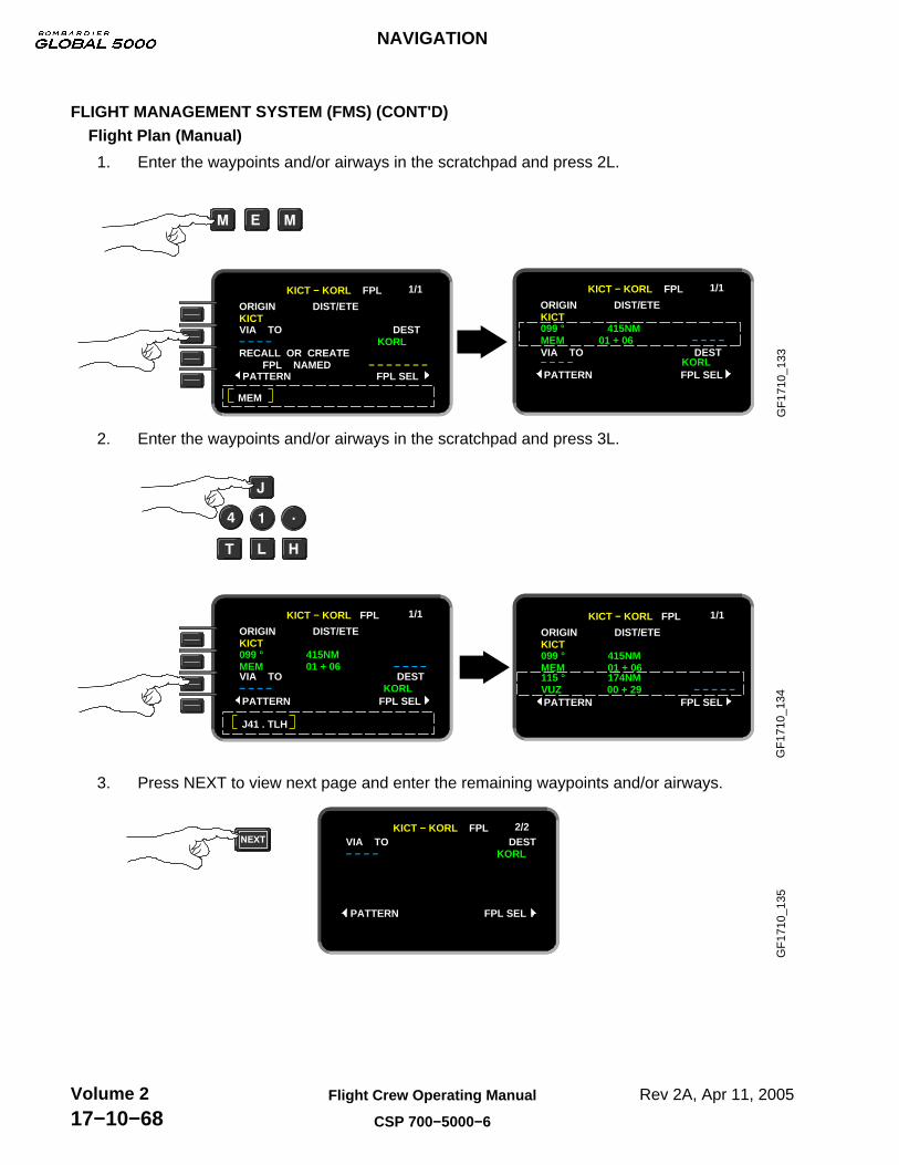
FLIGHT MANAGEMENT SYSTEM (FMS) (CONT'D)Flight Plan (Manual)
1. Enter the waypoints and/or airways in the scratchpad and press 2L.
GF
1710
_133
KICT − KORL FPL 1/1
KICTORIGIN DIST/ETE
− − − − KORLVIA TO DEST
FPL NAMED − − − − − − − RECALL OR CREATE
PATTERN FPL SEL
MEM
KICT − KORL FPL 1/1
KICTORIGIN DIST/ETE
MEM 01 + 06 − − − −099 ° 415NM
PATTERN FPL SEL − − − − KORLVIA TO DEST
2. Enter the waypoints and/or airways in the scratchpad and press 3L.
GF
1710
_134
KICT − KORL FPL 1/1
KICTORIGIN DIST/ETE
MEM 01 + 06 − − − −099 ° 415NM
PATTERN FPL SEL− − − − KORLVIA TO DEST
J41 . TLH
KICT − KORL FPL 1/1
KICTORIGIN DIST/ETE
MEM 01 + 06 099 ° 415NM
PATTERN FPL SELVUZ 00 + 29 − − − − −115 ° 174NM
3. Press NEXT to view next page and enter the remaining waypoints and/or airways.G
F17
10_1
35
KICT − KORL FPL 2/2
− − − − KORLVIA TO DEST
PATTERN FPL SEL
NAVIGATION
Rev 2A, Apr 11, 2005Flight Crew Operating Manual
CSP 700−5000−6
Volume 217−10−68

FLIGHT MANAGEMENT SYSTEM (FMS) (CONT'D)Flight Plan (Manual) (Cont’d)
Once all the flight plan waypoints and/or airways have been entered and the destination isinserted, select FPL SEL.
1. Press 4R to display FLIGHT PLAN SELECT page.
GF
1710
_136
KICT − KORL FPL 3/3
ORL 00 + 19 128 ° 115NM
PATTERN FPL SEL
KORL 00 + 00 0110 034 ° 0 . 2NM
KORL DEST
FPL PLAN SELECT 1/1
KICT − KORL ACTIVATEFLT PLAN
FPL LIST STORED FPL PREF
INVERT/ACTIVATE
2. Press 1R to activate flight plan.
GF
1710
_137
FPL PLAN SELECT 1/1
KICT − KORL ACTIVATEFLT PLAN
FPL LIST STORED FPL PREF
INVERT/ACTIVATE
KICT − KORL FPL 1/1
KICTORIGIN DIST/ETE
099 ° 415NM
DEPARTURE PERF INITVUZ 00 + 29 − − − / − − − −115 ° 174NM MEM 01 + 09 − − − / − − − −
3. Press 4R to display PERF INIT page.
GF
1710
_138
KICT − KORL FPL 1/1
KICTORIGIN DIST/ETE
MEM 01 + 09 − − − / − − − − 099 ° 415NM
DEPARTURE PERF INITVUZ 00 + 29 − − − / − − − − 115 ° 174NM
Departures
To select departure runway and take-off information:
1. Press 4L to display DEPARTURE RUNWAYS page.
GF
1710
_139
KICT − KORL FPL 1/1
ORIGIN DIST/ETE
DEPARTURE PERF INIT
DEPARTURE RUNWAYS 1/2
KICT
TAKEOFF01R 19L
01L 14
KICT
MEM 01 + 09 099 5 415NM
VUZ 00 + 29115 5 174NM
NAVIGATION
Rev 2A, Apr 11, 2005 Flight Crew Operating Manual
CSP 700−5000−6
Volume 217−10−69

FLIGHT MANAGEMENT SYSTEM (FMS) (CONT'D)Departures (Cont’d)
2. Select appropriate runway and press 4R to display TAKE-OFF page.
DEPARTURE RUNWAYS 1/2
KICT
TAKEOFF
01R 19L
01L 14
GF
1710
_140
TAKEOFF 1/3
01L KICT 10300RUNWAY LENGTH
OAT <−−−−−− SURFACE −−−−> W IND
PERF DATA CLIMB1296 / 29.90 1312 P ALT / B SET ELEV
−3° C / +27° F − − − ° / − − − −
To enter climb, cruise, descent and arrival information select line 4R on each subsequent page.
GF
1710
_141
300 / .80M CLIMB 1/1
FL 450TOC ALT ETE / ETA
SPD CMD
TAKEOFF CRUISE 22 . 8
DTG <− − − − −TOC− − − − −> FUEL REM300 / .80M
300 / .80M DESCENT 1/1
BOD ALT ETE / ETA
SPD CMD ANGLE
CRUISE ARRIVAL 22 . 8
DTG <− − − − −BOD− − − − −> FUEL REM300 / .80M 3 . 0 °
LONG RANGE CRUISE 1/2
FL 450 FL 445CRZ ALT OPT STEP
SPD CM STEP ETE / ETA
CLIMB DESCENT 22 . 8DTG <− − − −STEP− − − −> FUEL REM.77 M
ARRIVALS 1/1
RUNWAY AIRPORT
LANDING
STAR
APPROACH
KORL
NAVIGATION
Rev 2A, Apr 11, 2005Flight Crew Operating Manual
CSP 700−5000−6
Volume 217−10−70
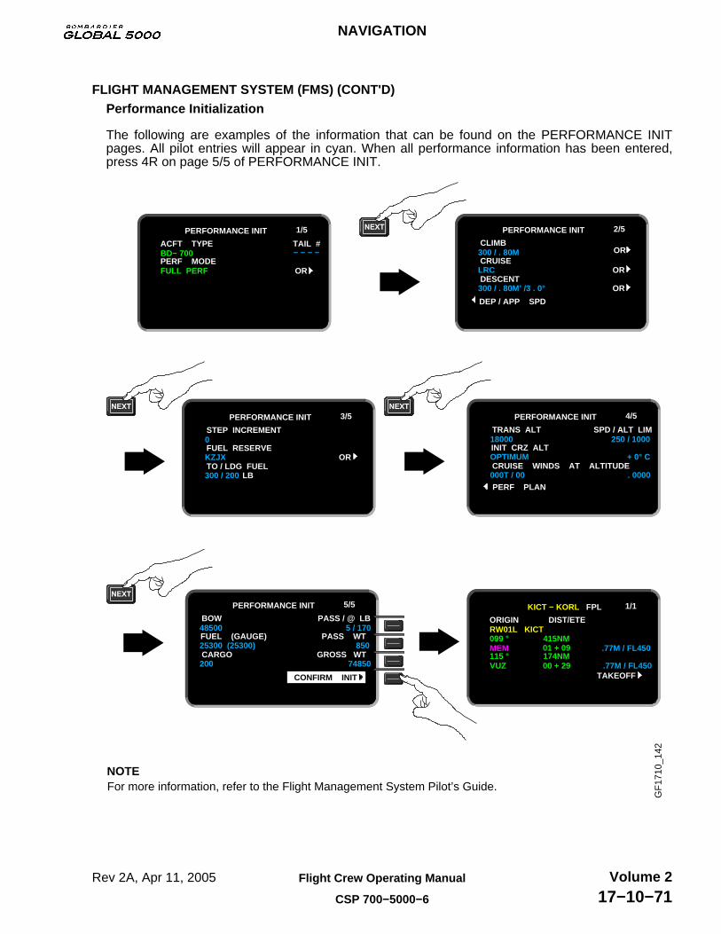
FLIGHT MANAGEMENT SYSTEM (FMS) (CONT'D)Performance Initialization
The following are examples of the information that can be found on the PERFORMANCE INITpages. All pilot entries will appear in cyan. When all performance information has been entered,press 4R on page 5/5 of PERFORMANCE INIT.
For more information, refer to the Flight Management System Pilot’s Guide. NOTE
GF
1710
_142
PERFORMANCE INIT 1/5
BD− 700 − − − −ACFT TYPE TAIL #
FULL PERF OR PERF MODE
PERFORMANCE INIT 2/5
300 / . 80M ORCLIMB
LRC OR CRUISE
300 / . 80M’ /3 . 0° OR DESCENT
DEP / APP SPD
PERFORMANCE INIT 3/5
0 STEP INCREMENT
KZJX OR FUEL RESERVE
300 / 200 LB TO / LDG FUEL
PERFORMANCE INIT 4/5
18000 250 / 1000TRANS ALT SPD / ALT LIM
OPTIMUM + 0° C INIT CRZ ALT
000T / 00 . 0000CRUISE WINDS AT ALTITUDE
PERF PLAN
PERFORMANCE INIT 5/5
48500 5 / 170BOW PASS / @ LB
25300 (25300) 850 FUEL (GAUGE) PASS WT
200 74850CARGO GROSS WT
CONFIRM INIT
KICT − KORL FPL 1/1
RW01L KICT ORIGIN DIST/ETE
MEM 01 + 09 .77M / FL450099 ° 415NM
TAKEOFFVUZ 00 + 29 .77M / FL450115 ° 174NM
NAVIGATION
Rev 2A, Apr 11, 2005 Flight Crew Operating Manual
CSP 700−5000−6
Volume 217−10−71

FLIGHT MANAGEMENT SYSTEM (FMS) (CONT'D)FMS Schematic
GF
1710
_143
FMS 1 FMS 2
VHFCOM 2
FMS 1 FMS 2
GNSSU1
AFCSEFISDAUIRSADCFWC
FMS 3(IF INSTALLED)
FMS 3
VHFCOM 1
HFCOM 1 LSS GPWS HF
COM 2
VORDMEADF TuneCOM Tune
VHFCOM 3
GNSSU2
(IF INSTALLED)
(IF INSTALLED) (IF INSTALLED)
RSB
ASCB
NAVIGATION
Rev 2A, Apr 11, 2005Flight Crew Operating Manual
CSP 700−5000−6
Volume 217−10−72

NAVIGATION DISPLAY UNIT (IF INSTALLED)
The Navigation Display Unit (NDU), also referred to as Lasertrack IV (LTRK), located on the pilot’sside panel, is a combined navigation computer and display unit, that is used to initialize up to threeinertial reference units (IRU) and to display navigation data based on a nine-waypoint flight plan andIRS inputs.
GF
1710
_144
ON KEY
FROM/TO/WPT
DATA DISPLAY
SPECIAL FUNCTIONKEYBOARD
NDU FAULTANNUNCIATOR
SYSTEM SELECTKEYBOARD
DATA SELECT
DISPLAY
KEYBOARD
DATA ENTRYKEYBOARD
The following describes the controls of the NDU:
ON Key
The ON Key is used to power on and power off the NDU.
NAVIGATION
Rev 2A, Apr 11, 2005 Flight Crew Operating Manual
CSP 700−5000−6
Volume 217−10−73

NAVIGATION DISPLAY UNIT (IF INSTALLED) (CONT'D)Data Entry Keyboard
The data entry keyboard is used to enter, display, modify, or transmit initialization, leg change andflight plan data. The data entry keyboard consists of the following:
GF
1710
_146
The enter key is used to accept entered data that is being displayed on the data display. Acue light illuminates to indicate that operator action is required.
The clear key is used to remove entered data and clear the display. A cue light illuminatesto indicate that operator action is required.
The back key is used to select the number and position of the previous waypoint for displaywhen the WPT cue light is illuminated.
Special Function Keyboard
The special function keyboard consists of the following:
The magnetic/true north key is used to indicate north reference. When the M cue light isilluminated, the NDU displays data referenced to magnetic north.
When the T cue light is illuminated, the NDU displays data referenced to true north.
The bright/dim key is used to control the lighting of the NDU display. When first pressedand held, the display intensity increases until the brightest level is reached. When pressed andheld a second time, the display intensity decreases until the dimmest level is reached.
The test key is used to start a test of all NDU annunciators, cue lights and display.
System Select Keys
The system select keys are used to select data for display from IRU1, IRU2, orIRU3. The NDU displays data from one IRU at a time. The selected IRUs cue light is illuminated.
NAVIGATION
Rev 2A, Apr 11, 2005Flight Crew Operating Manual
CSP 700−5000−6
Volume 217−10−74

NAVIGATION DISPLAY UNIT (IF INSTALLED) (CONT'D)Data Select Keyboard
The data select keyboard is used to select data for display. Each key contains a cue light thatindicates what type of data has been selected. When the WPT, LEG CHG, POS, or HDG STS keyis pressed, the operator can enter new data or modify the data that the NDU is displaying. Thedata select keyboard consists of the following:
GF
1710
_156
The waypoint key is used to build and display a flight plan consisting of one to ninewaypoints. When this key is repeatedly pressed, the NDU displays the successive flight planwaypoints by number and position.
The leg change key is used to define or modify the current flight plan leg by displaying theFROM and TO waypoint numbers. The current leg must be defined before navigation data can bedefined and displayed.
The crosstrack/desired track key is used to select and display the crosstrack error innautical miles from the current leg and the desired track of that leg.
The distance/time key is used to select and display the distance and time to the TOwaypoint based upon present position and current ground speed.
The track/ground speed key is used to select and display the current track and groundspeed.
The position key is used to initialize and display the present position of the airplane.
The wind direction/wind speed key is used to select and display the current wind directionand wind speed.
NAVIGATION
Rev 2A, Apr 11, 2005 Flight Crew Operating Manual
CSP 700−5000−6
Volume 217−10−75

NAVIGATION DISPLAY UNIT (IF INSTALLED) (CONT'D)Data Select Keyboard (Cont’d)
The heading/status key is used to display the current airplane heading. When the IRU isin align mode, the NDU displays alignment status (time remaining until NAV mode entry). Whenthe IRU is in NAV mode, the NDU displays heading in the left display. When the IRU is in attitudemode, the NDU displays magnetic heading in the left display and “ATT” in the right.
LEFT DISPLAY RIGHT DISPLAY
Displays
The NDU contains a data display and a FROM TO WPT display.
The NDU data display consists of two displays, a six position and a seven position display, eachhaving degree, decimal and minute indicators.
The FROM TO WPT display has three elements that display the FROM and TO waypoint numbersof the current leg and the number of the waypoint defined by the position being displayed.
GF
1710
_167
Fault Annunciator
The NDU FAULT annunciator is illuminated when the NDU BITE detects internal failures.
NAVIGATION
Rev 2A, Apr 11, 2005Flight Crew Operating Manual
CSP 700−5000−6
Volume 217−10−76

NDU UPDATE
To update the NDU (pre-flight), proceed as follows:
Power On• Power the NDU on.
GF
1710
_169
Test• Test the NDU displays, annunciators and cue lights.
GF
1710
_170
NAVIGATION
Rev 2A, Apr 11, 2005 Flight Crew Operating Manual
CSP 700−5000−6
Volume 217−10−77

NDU UPDATE (CONT'D)Position Entry
The following procedures can be used for position entry (initialization), during IRS alignment andalign downmode.
GF
1710
_171
1 Press POS key.
2 Press N/2 or S/8.
3 Enter Latitude (example KICT).
4 Press ENT key to transmit lattitude to all IRUs.
6 Enter Longitude (example KICT).
5 Press W/4 or E/6.
7 Press ENT key to transmit longitude to all IRUs.
8 Press HDG STS key and observe time to complete alignment in right display.
NAVIGATION
Rev 2A, Apr 11, 2005Flight Crew Operating Manual
CSP 700−5000−6
Volume 217−10−78

NDU UPDATE (CONT'D)Position Entry (Cont’d)
Enter the magnetic heading when the latitude mode has been selected.
GF
1710
_172
1 Press appropriate SYSTEM SELECT key.
2 Press HDG STS.
3 Enter magnetic heading (example KICT).
4 Press ENT key to transmit heading to all IRUs.
Ensure IRS mode selector is set to ATT.
NOTE For more information, refer to the LASERTRACK Navigation Display Unit Pilot’s Manual
IRS1 IRS2 IRS3
NAVIGATION
Rev 2A, Apr 11, 2005 Flight Crew Operating Manual
CSP 700−5000−6
Volume 217−10−79

NDU SCHEMATIC
GF
1710
_173
IAC 1 IAC 2 IAC 3
IRU 1 IRU 2 IRU 3
NAVIGATION
Rev 2A, Apr 11, 2005Flight Crew Operating Manual
CSP 700−5000−6
Volume 217−10−80

GLOBAL POSITIONING SYSTEM (GPS)
The GPS is used to determine airplane position and provides supplementary information to FMS andEGPWS. The GPS calculates the latitude, longitude, altitude, accurate time, date, true heading andground speed.
The Global Navigation System Sensor Unit (GNSSU), is a GPS receiver that receives satellitesignals from the NAVSTAR GPS satellite constellation (21 operational satellites and 3 active spares)and uses the satellite data to compute the airplane position.
The GNSSU has a Receiver Autonomous Integrity Monitor (RAIM) function. The RAIM monitors thestatus of the satellites that are used for calculations. The output of the RAIM function is an estimateof GPS position error. The RAIM value is sent to the FMS and the FMS uses this data to determine ifit can use the GPS for navigation.
MODES OF OPERATION:
The GNSSU operational modes are as follows:
• Self-Test Mode − The GNSSU is in the self-test mode for approximately 5 seconds. When theself-test mode is complete, the GNSSU enters the initialization mode.
• Initialization Mode − The GNSSU automatically enters the initialization mode to initialize itshardware. When the hardware is initialized, the GNSSU enters the acquisition mode.
• Acquisition Mode − The GNSSU enters the acquisition mode to acquire satellites (minimum 4),or from other modes (NAV or Aided), when it does not have sufficient satellite and/or aidingdata to remain in either the NAV or the Aided mode. From the acquisition mode, the GNSSUenters the NAV mode.
• Navigation (NAV) Mode − The GNSSU enters the NAV mode when it has computed anavigation solution that provides position, velocity, and time measurements. The GNSSUsends GPS position data to the FMS. From the NAV mode the GNSSU enters the acquisitionmode or aided mode.
• Aided Mode − The GNSSU enters the aided mode when there is insufficient satellite and/oraltitude information, but external-aided data (inertial velocities from the FMS) is available tocontinue to update the NAV filter. While in this mode, the GNSSU provides valid time outputs.From this mode, the GNSSU enters the NAV or acquisition mode.
• Altitude Aiding Mode − The GNSSU enters the altitude aiding mode if satellite measurements(less than 4) are not sufficient to maintain integrity or remain in the NAV mode. This mode usesaltitude data from the ADC to aid the navigation solution and integrity monitoring duringextended periods of insufficient satellite coverage and geometry. When the calibrated pressurealtitude deviation estimate is out of limits, it reverts to the aided mode. From this mode, theGNSSU enters the NAV or aided modes.
• Fault Mode − The GNSSU enters the fault mode when any faults in the GNSSU is detected.This mode supersedes all other modes. Any faults will be reported on the FMS CDU. The FMS
MSG indicator MSG will illuminate and GPS 1 (2) FAILED message will appear in the FMSscratchpad.
GPS 1 FAILED
The control stations that continuously track and monitor the satellites, are located in AscensionIsland, Diego Garcia, Hawaii, Kawajalein Island and Colorado Springs. GPS has an accuracy of 100meters in 95% of the position fixes.
NAVIGATION
Rev 2A, Apr 11, 2005 Flight Crew Operating Manual
CSP 700−5000−6
Volume 217−10−81

MODES OF OPERATION: (CONT'D)GPS Access
To access the GPS on the FMS CDU, proceed as follows:
GF
1710
_176
NAV INDEX 1/2
FPL LIST FPL SEL
WPT LIST DATA BASE
DEPARTURE ARRIVAL
POS SENSORS TUNE
NAV INDEX 1/2
FPL LIST FPL SEL
WPT LIST DATA BASE
DEPARTURE ARRIVAL
POS SENSORS TUNE
POS SENSORS 1/2
FMS POS UPDATE
IRS 1 STATUS
IRS 2 STATUS
VOR / DME POSIT INIT
N33 ° 26 . 6 W112 ° 12 . 1
N33 ° 26 . 6 W112 ° 12 . 1
N33 ° 26 . 6 W112 ° 12 . 1
POS SENSORS 1/2
FMS POS UPDATE
IRS 1 STATUS
IRS 2 STATUS
VOR / DME POSIT INIT
N33 ° 26 . 6 W112 ° 12 . 1
N33 ° 26 . 6 W112 ° 12 . 1
N33 ° 26 . 6 W112 ° 12 . 1
POS SENSORS 2/2
FMS POS UPDATE
GPS STATUS
VOR / DME POSIT INIT
N33 ° 26 . 6 W112 ° 12 . 1
N34 ° 02 . 6 W112 ° 02 . 3
GPS Status
GPS STATUS 1/2 displays the following information:
• GPS position• Groundspeed• Altitude• Miles from FMS position
NAVIGATION
Rev 2A, Apr 11, 2005Flight Crew Operating Manual
CSP 700−5000−6
Volume 217−10−82

MODES OF OPERATION: (CONT'D)GPS Status (Cont’d)
To view the GPS STATUS 1/2 on the FMS CDU, proceed as follows:
GF
1710
_177
1 Press STATUS key.
POS SENSORS 2/2
FMS POS UPDATE
GPS STATUS
VOR / DME POSIT INIT
N33 ° 26 . 6 W112 ° 12 . 1
N34 ° 02 . 6 W112 ° 02 . 3
GPS 1 STATUS 1/2
GPS POSITION
GRD SPD = 310 GPS ALT
MILES FR FMS POS
POS SENSORS PRED RAIM
N34 ° 02 . 6 W112 ° 02 . 3
N302 KT E68 KT 14999
NO . 1 W 4 . 4 TOTAL 4 . 4
GPS STATUS 2/2 displays the following information:
• Receiver Autonomous Integrity Monitor (RAIM).• Figure of Merit (FOM).• Horizontal Dilution of Precision (HDOP).• Vertical Dilution of Precision (VDOP).• Time (UTC) and Date.• Operating Mode.• Satellites Tracked.
RAIM and FOM indicate current uncertainty of position expressed in nautical miles. HDOP andVDOP are numbers that rate current satellite geometry in the horizontal and vertical axis with 1being the best geometry. Normally HDOP and VDOP numbers are below 10.
To view the GPS STATUS 2/2 on the FMS CDU, proceed as follows:
GF
1710
_178
1 Press NEXT function key.
NOTEFor more information, refer to the Flight Management System Pilot’s Guide.
GPS 1 STATUS 1/2
GPS POSITION
GRD SPD = 310 GPS ALT
MILES FR FMS POS
POS SENSORS PRED RAIM
N34 ° 02 . 6 W112 ° 02 . 3
N302 KT E68 KT 14999
NO . 1 W 4 . 4 TOTAL 4 . 4
GPS 1 STATUS 2/2
RAIM = 0 . 10 NM
POS SENSORS PRED RAIM
FOM = 0 . 05 NM
MODE = NAVIGATION
HDOP = 2 UTC 1730
VDOP = 2 DATE 20APR97
SATELLITES TRACKED = 7
NAVIGATION
Rev 2A, Apr 11, 2005 Flight Crew Operating Manual
CSP 700−5000−6
Volume 217−10−83
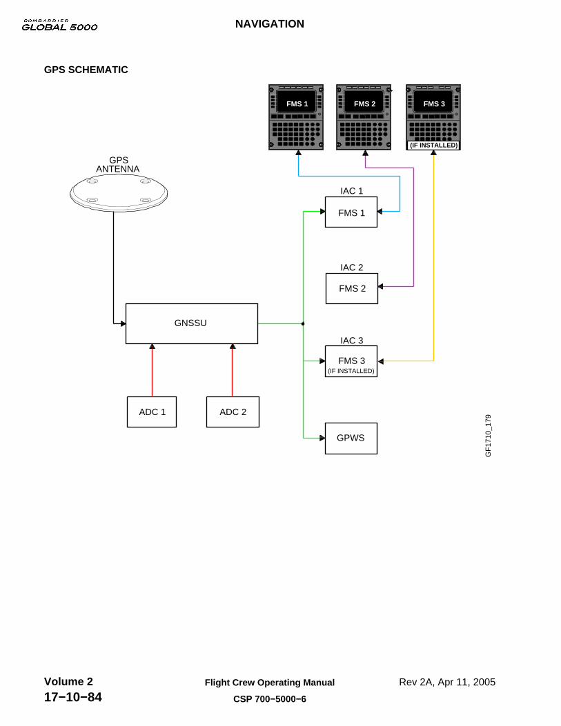
GPS SCHEMATIC
GF
1710
_179
GNSSU
ADC 1 ADC 2
FMS 1
FMS 3
IAC 1
IAC 2
IAC 3
GPWS
GPSANTENNA
FMS 1 FMS 2 FMS 3
(IF INSTALLED)
(IF INSTALLED)
FMS 2
NAVIGATION
Rev 2A, Apr 11, 2005Flight Crew Operating Manual
CSP 700−5000−6
Volume 217−10−84

NAVIGATION SYSTEM EICAS MESSAGES
GF
1710
_180
FMS 1−2−3 FAILIndicates that respective FMS has failed. GPWS SYSTEM FAIL
Indicates GPWS computer has failed.
TERR FAILIndicates terrain alerting function has failed.
WINDSHEAR FAILIndicates that windshear alerting function has failed.
GND PROX FAILIndicates that GPWS is inoperative. GND PROX FAIL will also be annunciated when the FLAP OVERRIDE switch is OVRD and IAS > 250 knots.
GPWS FLAP OVRDIndicates that FLAP OVRD switch has been selected and flap aural warning has been muted.
GPWS G/S OVRDIndicates that G/S WARN switch has been selected and glideslope aural has been muted.
LSTRK FAILIndicates that Lasertrack is inoperative, or has been turned OFF.
FMS 1 FAILFMS 2 FAILFMS 3 FAILGPWS SYSTEM FAILGND PROX FAILLSTRK FAILTERR FAILWINDSHEAR FAILGPWS FLAP OVRDGPWS G/S MUTED
NAVIGATION
Rev 2A, Apr 11, 2005 Flight Crew Operating Manual
CSP 700−5000−6
Volume 217−10−85

NAVIGATION
Rev 2A, Apr 11, 2005Flight Crew Operating Manual
CSP 700−5000−6
Volume 217−10−86
THIS PAGE INTENTIONALLY LEFT BLANK

CB - NAV SYSTEM
GF
1720
_001
STAT SYS BUS PREV CNTL TESTPAGE
NEXTPAGE
EMERCNTL
BUSSYSTEMCIRCUIT BREAKER
BRT
2/2CIRCUIT BREAKER − SYSTEM
THRUST REV
OXYGEN
HYD
ICE
IND/RECORD
LDG GEAR
LIGHTS
OIL
NAV
DC ESS
1/6CB − NAV SYSTEM
ADF 2
DME 1
FMS 1 CDU
FMS 2 CDU
INADF 1
IN
IN
IN
IN
DC 1
DC ESS
DC 2
DME 2
BATT
DC 2
IN
DC 1
2/6CB − NAV SYSTEM
GPS 1
GPS 2
HUD
IRS 1 FAN
INFMS 3 CDU
IN
IN
IN
IN
DC 1
DC 1
DC 2
GPWS
DC 2
DC ESS
IN
IRS 3 PWR A
IRS 3 PWR B
LIGHTNING SENSOR
MFD 1 CTLR
MFD 2 CTLR
IN
IN
IN
IN
DC 1
DC ESS
DC 1
BATT
DC 2 IN
4/6
RAD ALT 2
STBY ADI
STBY ALT/ASI
TCAS
VOR/ILS 1
INRAD ALT 1
IN
IN
IN
IN
DC 1
DC 2
AV BATT
DC ESS
DC ESS
DC 2
CB − NAV SYSTEM
IN
5/6
DC 2
3/6CB − NAV SYSTEM
IRS 1 PWR B
IRS 2 FAN
IRS 2 PWR B
IRS 3 FAN
INIRS 1 PWR A
IN
IN
IN
IN
DC ESS
BATT
DC 2
IRS 2 PWR A
DC ESS
DC 1
IN
VOR/ILS 3 (OPT)
WX RADAR
WX RADAR CTLR 1
WX RADAR CTLR 2
INVOR/ILS 2
IN
IN
IN
IN
DC ESS
DC 1
DC 1
DC 1
DC 1
CB − NAV SYSTEM 6/6
CB − NAV SYSTEM
CCBP
NAVIGATION
EMS CIRCUIT PROTECTION
Rev 2A, Apr 11, 2005 Flight Crew Operating Manual
CSP 700−5000−6
Volume 217−20−1

NAVIGATION
EMS CIRCUIT PROTECTION
Rev 2A, Apr 11, 2005Flight Crew Operating Manual
CSP 700−5000−6
Volume 217−20−2
THIS PAGE INTENTIONALLY LEFT BLANK